ICOM orporated 339300 HF/VHF/UHF All Mode Transceiver User Manual manual draft ALL
ICOM Incorporated HF/VHF/UHF All Mode Transceiver manual draft ALL
UserManual.wiki
>
ICOM orporated
>
339300 User Manual
User Manual
Navigation menu
Upload a User Manual
Namespaces
Wiki Guide
HTML
PDF
Info
Views
User Manual
Discussion / Help
Navigation
![PRECAUTIONSii123456789101112131415161718192021R DANGER HIGH VOLTAGE! NEVER touch an antenna or internal antenna connector during transmission. This may result in an electrical shock or burn.R WARNING RF EXPOSURE! This device emits Radio Frequency (RF) energy. Extreme caution should be observed when operating this device. If you have any questions regarding RF exposure and safety stan-dards please refer to the Federal Communications Commission Offi ce of Engineering and Technology’s report on Evaluating Compliance with FCC Guidelines for Human Radio Frequency Electromagnetic Fields (OET Bulletin 65).R WARNING! NEVER operate the transceiver while driving a vehicle. Safe driving requires your full attention—anything less may result in an accident.R WARNING! NEVER operate the transceiver with an earphone, headphones or other audio accessories at high volume levels. Hearing experts advise against continuous high volume operation. If you experience a ringing in your ears, reduce the volume level or dis-continue use.R WARNING! NEVER apply AC power to the [DC13.8V] connector on the transceiver rear panel. This could cause a fi re or damage the transceiver.R WARNING! NEVER apply more than 16 V DC to the [DC13.8V] connector on the transceiver rear panel or use reverse polarity. This could cause a fi re or damage the trans-ceiver.R WARNING! NEVER cut the DC power cable be-tween the DC plug and fuse holder. If an incorrect connec-tion is made after cutting, the transceiver might be dam-aged.R WARNING! NEVER let metal, wire or other objects touch any internal part or connectors on the rear panel of the transceiver. This may result in an electric shock or this could cause a fi re or damage the transceiver.R WARNING! NEVER operate or touch the trans-ceiver with wet hands. This may result in an electric shock or may damage the transceiver.R WARNING! Immediately turn the transceiver power OFF and remove the power cable if it emits an abnormal odor, sound or smoke. Contact your Icom dealer or dis-tributor for advice.CAUTION: NEVER expose the transceiver to rain, snow or any liquids.CAUTION: NEVER change the internal settings of the transceiver. This may reduce transceiver perfor-mance and/or damage to the transceiver. DO NOT operate the transceiver near unshielded electrical blasting caps or in an explosive atmosphere.DO NOT use harsh solvents such as benzine or al-cohol to clean the transceiver, as they will damage the transceiver’s surfaces. If the transceiver becomes dusty or dirty, wipe it clean with a soft, dry cloth.DO NOT use or place the transceiver in areas with tem-peratures below –10°C (+14°F) or above +60°C (+140°F). Be aware that temperatures on a vehicle’s dashboard can exceed +80°C (+176°F), resulting in permanent damage to the transceiver if left there for extended periods.DO NOT place the transceiver in excessively dusty envi-ronments or in direct sunlight.DO NOT place the transceiver against walls or putting any-thing on top of the transceiver. This will obstruct heat dissipa-tion.Place the transceiver in a secure place to avoid inadvertent use by children.During mobile operation, NEVER place the transceiver where air bag deployment may be obstructed.During mobile operation, DO NOT place the transceiver where hot or cold air blows directly onto it.During mobile operation, DO NOT operate the transceiver without running the vehicle’s engine. When the transceiver’s power is ON and your vehicle’s engine is OFF, the vehicle’s battery will soon become exhausted.Make sure the transceiver power is OFF before starting the vehicle engine. This will avoid possible damage to the trans-ceiver by ignition voltage spikes.During maritime mobile operation, keep the transceiver and microphone as far away as possible from the magnetic navi-gation compass to prevent erroneous indications.BE CAREFUL! The rear panel will become hot when op-erating the transceiver continuously for long periods of time.BE CAREFUL! If a linear amplifi er is connected, set the transceiver’s RF output power to less than the linear ampli-fi er’s maximum input level, otherwise, the linear amplifi er will be damaged.Use Icom microphones only (supplied or optional). Other manufacturer’s microphones have different pin assignments, and connection to the IC-7100 may damage the transceiver.](https://usermanual.wiki/ICOM-orporated/339300/User-Guide-2000118-Page-3.png)
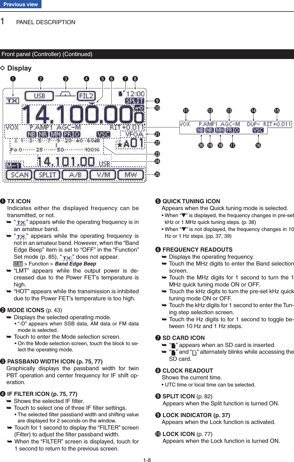
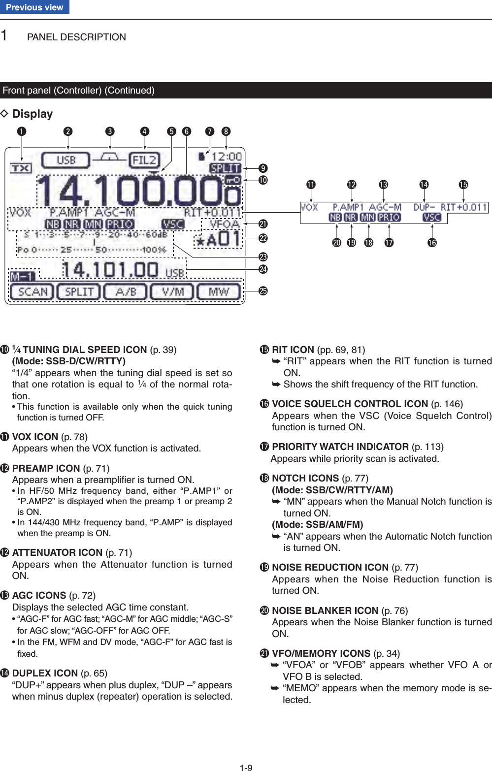
![1PANEL DESCRIPTION1-2Previous viewFront panel (Controller)q POWER SWITCH/AF VOLUME [PWR]/[AF] (p. 44)Push to turn ON the transceiver power. ➥ • First, confi rm the DC power source is turned ON.Hold down for 1 second to turn OFF the power. ➥ Rotate to adjust audio output level. ➥IncreasesDecreasesw RF GAIN CONTROL/ SQUELCH CONTROL [RF/SQL] (p. 44) Rotate to adjust the RF gain and squelch threshold level. The squelch removes noise output to the speaker when no signal is received. (closed condition) • The squelch is particularly effective for AM and FM, but also works in other modes. • The 12 to 1 o’clock position is recommended for the most effective use of the [RF/SQL] control. • [RF/SQL] operates as only an RF gain control in SSB, CW and RTTY (Squelch is fi xed open), or a squelch con-trol in AM, FM and DV (RF gain is fi xed at maximum sen-sitivity), when “Auto” is selected as the “RF/SQL Control” item in the “Function” Set mode. (p. 162) SET > Function > RF/SQL Control• When used as an RF gain/squelch controlMaximum RF gainS-meter squelchNoise squelch (FM/DV modes)Squelch is open.RF gain adjustablerangeRecommended level• When used as an RF gain control(Squelch is fi xed open; SSB, CW and RTTY only)Minimum RF gainAdjustablerangeMaximum RF gainWhile rotating the RF gain control, a faint noise may be heard. This comes from the DSP unit and does not indicate an equipment malfunction.• When used as a squelch control(RF gain is fi xed at maximum.)Squelch is open.S-meter squelchS-meter squelchthresholdNoise squelch threshold (FM mode)Shallow DeepNoise squelch (FM/DV modes)PBT RITTX / RXPWRAF RF/SQLCLRM-CH BANKRITTUNER/CALLMENUMIC/RF PWRNBSPEED/PITCHSETQUICKNOTCHDRAUTO TUNERX➔CSXFCSPEECHMPADNRP.AMPATTi7100wq](https://usermanual.wiki/ICOM-orporated/339300/User-Guide-2000118-Page-6.png)
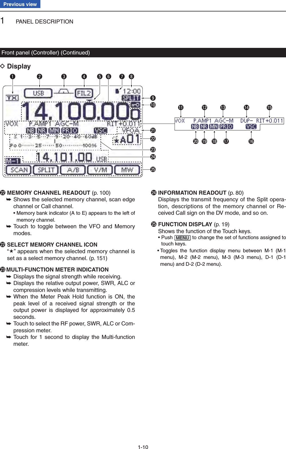
![1PANEL DESCRIPTION1-3Previous viewe TX/RX LED Lights green when the squelch opens, or a signal ➥is received. Lights red during transmit. ➥r MEMORY BANK CONTROL [BANK] ❍ When the both PBT and RIT LEDs are OFF Rotate to select a Memory bank. ❍ When the PBT LED (y) rights green (Mode: SSB/CW/RTTY/AM) Rotate to adjust the receiver’s IF fi lter passband width using the DSP circuit. ❍ When the RIT LED (u) rights orange Disable this control.t M-CH CONTROL/CLEAR KEY [M-CH]/[CLR] Push to select the action of the [M-CH/BANK] con-trols as the Memory/Bank selection, PBT control or RIT control. ❍ When the both RIT and PBT LEDs are OFF Rotate to select a Memory channel. ❍ When the RIT LED rights orange ➥ Rotate to adjust the RIT frequency shift. • The frequency shift range is ±9.99 kHz in 10 Hz steps. The control tunes in 1 Hz steps when the operating frequency readout is set to the 1 Hz step readout. ➥ Hold down for 1 second to clear the RIT shift frequency. ✔ What is the RIT function?The RIT (Receiver Incremental Tuning) shifts the re-ceive frequency without shifting the transmit frequency.This is useful for fi ne tuning stations calling you off-fre-quency or when you prefer to listen to slightly different-sounding voice characteristics, and so on. ❍ When the PBT LED rights green (Mode: SSB/CW/RTTY/AM) ➥ Rotate to adjust the receiver’s IF fi lter pass-band width using the DSP circuit. ➥ Hold down for 1 second to reset the PBT set-tings. • The PBT is adjustable in 50 Hz steps in the SSB/CW/RTTY modes, and 200 Hz in the AM mode. In this time, the shift value changes in 25 Hz steps in the SSB/CW/RTTY modes, and 100 Hz in the AM mode. • The PBT controls function as an IF shift control.✔ What is the PBT control?The PBT function electronically modifi es the IF pass-band width to reject interference. This transceiver uses the DSP circuit for the PBT function.y PBT LED Lights green when the [M-CH/BANK] controls act as the PBT control. • Push the [M-CH] switch to select as the PBT control.u RIT LED Lights orange when the RIT function turns ON. ➥ Lights orange when the [M-CH/BANK] ➥ controls act as the RIT control. • Push the [M-CH] switch to select as the RIT con-trol. • The RIT control is the inner control. The outer control is disabled.i RIT KEY RIT (p. 69) Push to turn the RIT function ON or OFF. ➥ • Use the [M-CH] control to vary the RIT frequency. ➥ Hold down for 1 second to add the shift frequency of the RIT function to or subtract it from the dis-played frequency.Front panel (Controller) (Continued)PBT RITTX / RXPWRAF RF/SQLCLRM-CH BANKRITTUNER/CALLMENUMIC/RF PWRNBSPEED/PITCHSETQUICKNOTCHDRAUTO TUNERX➔CSXFCSPEECHMPADNRP.AMPATTi7100teryui](https://usermanual.wiki/ICOM-orporated/339300/User-Guide-2000118-Page-7.png)
![1PANEL DESCRIPTION1-4Previous viewo ANTENNA TUNER/CALL KEY TUNER/CALL ❍ ANTENNA TUNER KEY Operation (p. 139) (Frequency band: HF/50 MHz) ➥ Push to turn the optional antenna tuner ON or OFF (bypass). ➥ Hold down for 1 second to manually start the antenna tuner. • If the tuner cannot tune the antenna within 20 sec-onds, the tuning circuit is automatically bypassed. ❍ CALL KEY Operation (p. 139) (Frequency band: 144/430 MHz) Push to select the call channel.!0 MENU SWITCH MENU (p. 19) Push to change the set of functions assigned to touch keys. • Toggles the function display menu between M-1 (M-1 menu), M-2 (M-2 menu), M-3 (M-3 menu), D-1 (D-1 menu) and D-2 (D-2 menu).!1 MIC GAIN/RF POWER ADJUSTMENT KEY MIC/RF PWR (p. 19) Push to open the MIC gain/RF power adjustment display. • Rotate [M-CH] to adjust the MIC gain. • Rotate [BANK] to adjust the RF power.Frequency band RF output power rangeHF/50 MHz 2 to 100 W (AM: 1 to 30 W)144 MHz 2 to 100 W430 MHz 2 to 75 W • Push again to close the window.!2 NOISE BLANKER KEY NB (p. 76) (Mode: SSB/CW/RTTY/AM) Push to turn the noise blanker ON or OFF. ➥ The noise blanker reduces pulse-type noise such as that generated by vehicle ignition systems. The noise blanker is not effective for non-pulse-type noise. • “NB” appears when the noise blanker is ON. Hold down for 1 second to display the “NB” screen. ➥Push to return to the previous screen.!3 KEY SPEED/CW PITCH ADJUSTMENT KEY SPEED/PITCH (p. 19) Push to open the Key speed/CW pitch adjustment display. • Rotate [M-CH] to adjust the keying speed of the inter-nal electronic CW keyer to between 6 wpm (minimum) and 48 wpm (maximum). • Rotate [BANK] to shift the received CW audio pitch and the CW sidetone pitch without changing the operat-ing frequency. • The CW pitch can be adjusted from 300 to 900 Hz in ap-proximately 5 Hz steps. • Push again to close the window.!4 NOISE REDUCTION KEY NR (p. 77)Push to turn DSP noise reduction ON or OFF. ➥ • “NR” appears when noise reduction is ON. Hold down for 1 second to display the “NR” screen. ➥Push to return to the previous screen. • Rotate the Dial to adjust the DSP noise reduction level. Set for maximum readability.Front panel (Controller) (Continued)PBT RITTX / RXPWRAF RF/SQLCLRM-CH BANKRITTUNER/CALLMENUMIC/RF PWRNBSPEED/PITCHSETQUICKNOTCHDRAUTO TUNERX➔CSXFCSPEECHMPADNRP.AMPATTi7100o!0 !2 !4!1 !3](https://usermanual.wiki/ICOM-orporated/339300/User-Guide-2000118-Page-8.png)
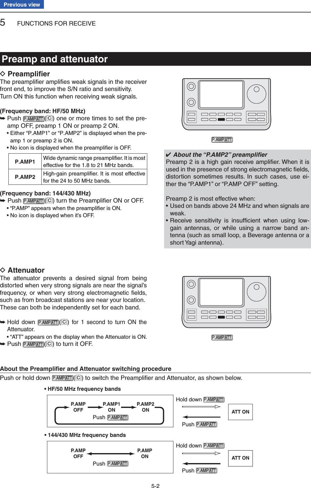
![1PANEL DESCRIPTION1-5Previous view!5 PREAMP•ATTENUATOR KEY P.AMPATT ❍ PREAMP KEY Operation (p. 71) (Frequency band: HF/50 MHz) Push to select one of two receive RF preampli-fi ers, or to bypass them. • “P. AMP1” is a wide dynamic range preamplifi er. It is most effective for the 1.8 to 21 MHz bands. • “P. AMP2” is a high-gain preamplifi er. It is most effec-tive for the 24 to 50 MHz bands. • No indicator appears when the preamplifi ers are not selected.✔ What is the preamplifi er?The preamplifi er amplifi es signals in the front end to improve the S/N ratio and sensitivity. Select “P. AMP1” or “P. AMP2” when receiving weak sig-nals. (Frequency band: 144/430 MHz) Push to turn the preamplifi er ON or OFF. • “P.AMP” appears when the preamplifi er is ON. ❍ ATTENUATOR KEY Operation (p. 71) ➥ Hold down for 1 second to turn ON the attenu-ator. • “ATT” appears when the attenuator is ON. ➥ Push to turn OFF the attenuator. • “ATT” disappears.✔ What is the attenuator?The attenuator prevents a desired signal from be-ing distorted when very strong signals are near it, or when very strong electromagnetic fi elds, such as from a broadcasting station, are near your lo-cation.!6 NOTCH SWITCH NOTCH (p. 77) (Mode = Auto notch: SSB/AM/FM Manual notch: SSB/CW/RTTY/AM) ➥In the SSB and AM modes, push to toggle the notch function between auto, manual and OFF. • Either the Auto or Manual notch function can be turned OFF in the “[NOTCH] Switch (SSB)/(AM)” items of the “Function” Set mode. (p. 36) SET > Function > [NOTCH] Switch (SSB) SET > Function > [NOTCH] Switch (AM) ➥In the FM mode, push to turn the Auto Notch func-tion ON or OFF. ➥ In the CW or RTTY mode, push to turn the Manual Notch function ON or OFF. • “MN” appears when the Manual Notch function is ON. • “AN” appears when the Auto Notch function is ON. • No indicator appears when the notch fi lter is OFF. ➥ Hold down for 1 second to display the “NOTCH” screen. Push to return to the previous screen. • Rotate the Dial to adjust the notch frequency to reject an interfering signal while the manual function is ON. • Notch fi lter center frequency: SSB/RTTY: –1040 Hz to +4040 Hz CW: CW pitch frequency –2540 Hz to CW pitch frequency +2540 Hz AM: –5060 Hz to +5100 Hz✔ What is the notch fi lter?The notch fi lter is a narrow fi lter that eliminates un-wanted CW or AM carrier tones, while preserving the desired voice signal. The DSP circuit automati-cally adjusts the notch frequency to effectively elimi-nate unwanted tones.Front panel (Controller) (Continued)PBT RITTX / RXPWRAF RF/SQLCLRM-CH BANKRITTUNER/CALLMENUMIC/RF PWRNBSPEED/PITCHSETQUICKNOTCHDRAUTO TUNERX➔CSXFCSPEECHMPADNRP.AMPATTi7100!6!5](https://usermanual.wiki/ICOM-orporated/339300/User-Guide-2000118-Page-9.png)
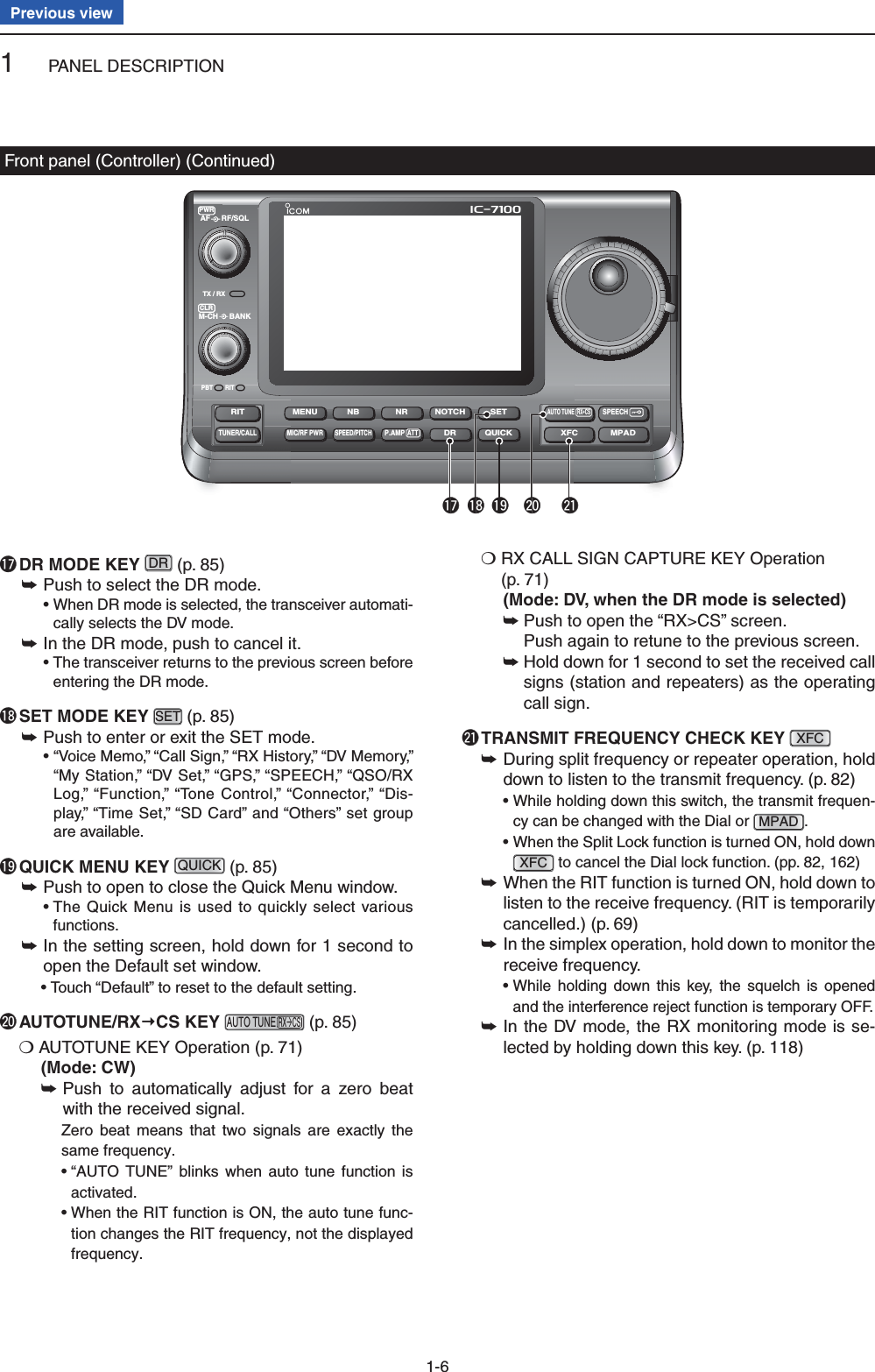
![1PANEL DESCRIPTION1-7Previous view@2 SPEECH/LOCK SWITCH SPEECH ❍ SPEECH KEY Operation (p. 45) Push to audibly announce the S-meter level, the displayed frequency and the operating mode. • The S-Level announcement can be turned OFF in the “S-Level SPEECH” item of the “SPEECH” Set mode. (p. 164) SET > SPEECH > S-Level SPEECH • When RIT is ON, the RIT offset is not included in the frequency announcement. ❍ LOCK KEY Operation (p. 77) Hold down for 1 second to turn the Lock function ON or OFF. • The function electronically locks the Dial. • “ ” appears when the function is ON. • The function can be select the Dial lock and Panel lock in the “Lock Function” item of the “Function” Set mode. (p. 164) SET > Function > Lock Function NOTE: The [SPEECH/LOCK] switch operation to activate the voice synthesizer or the Lock func-tions can be replaced in the “[SPEECH/LOCK] Switch” item of the “Function” Set mode. (p. 164) SET > Function > Lock Function@3 MEMO PAD KEY MPAD (p. 144) Push to sequentially call up the contents from the ➥memo pads. The 5 (or 10) most recently programmed frequen-cies and operating modes can be recalled, start-ing from the most recent. • The memo pad capacity can be increased from 5 to 10 in the “Memopad Numbers” item of the “Function” Set mode (p. 164) SET > Function > Memopad Numbers Hold down for 1 second to write the displayed ➥data into a memo pad. • The 5 most recent entries remain in the memo pads.@4 MAIN DIAL Rotate to change the displayed frequency, select the Set mode settings, and so on.@5 MAIN DIAL TENSION LATCH Select the Dial drag. • Three positions are selectable. The upper side setting turns on clicks as the dial is turned.Front panel (Controller) (Continued)PBT RITTX / RXPWRAF RF/SQLCLRM-CH BANKRITTUNER/CALLMENUMIC/RF PWRNBSPEED/PITCHSETQUICKNOTCHDRAUTO TUNERX➔CSXFCSPEECHMPADNRP.AMPATTi7100@2 @3@4@5](https://usermanual.wiki/ICOM-orporated/339300/User-Guide-2000118-Page-11.png)
![1PANEL DESCRIPTION1-12Previous viewD Function keys on M-1 displaySCAN KEY [SCAN] (p. 147)Touch to display the “SCAN” screen.SPLIT SWITCH [SPLIT] (p. 82)➥ Touch to turn the split function ON or OFF. • “SPLIT” appears when the split function is ON.➥ Touch for 1 second to activate the quick split func-tion. • The transmit frequency shifts from the receive frequency according to the “SPLIT Offset” option in the Set mode. (p. 162) • The quick split function can be turned OFF in the “Quick SPLIT” item of the Set mode. (p. 162)VFO SELECT SWITCH [A/B] (pp. 32, 34)➥ Touch to select either VFO A or VFO B.➥ Touch for 1 second to equalize the undisplayed VFO settings to that of the displayed VFO.VFO/MEMORY SWITCH [V/M]➥ Touch to switch between the VFO and memory modes. (pp. 34, 139) • Touching Memory channel also selects the VFO or mem-ory modes. (p. 162)➥ Touch for 1 second to copy the memory contents to the displayed VFO on the MAIN Band. (p. 142)MEMORY WRITE SWITCH [MW] (p. 140) Touch for 1 second to store VFO data into the selected memory channel.• This can be done in both the VFO and memory modes.D Function keys on M-2 displayDUPLEX KEY [DUP] (p. 65)➥ Touch to select the duplex direction, or to turn OFF the function. • “DUP–” or “DUP+” is displayed during duplex operation.➥ In the FM mode, touch for 1 second to turn the one-touch repeater function ON or OFF.AGC KEY [AGC] (p. 72)(Mode: SSB/SSB-D/CW/RTTY/AM/AM-D)➥ Touch to select the time constant of the AGC circuit.➥ Touch for 1 second to display the “AGC” screen.TONE SQUELCH KEY [TONE] (pp. 62–64)(Mode: FM)➥ Touch to select a tone function between subaudible (repeater) tone, tone squelch and DTCS code.➥ Touch for 1 second to display the “TONE” screen of the selected tone function.DIGITAL SQUELCH KEY [DSQL] (p. 114)(Mode: DV)➥ Push to select a digital squelch function between digital call sign squelch and digital code squelch.➥ Hold down for 1 second to display the “DSQ” screen (digital squelch).MEMORY KEYER MENU KEY [KEYER] (p. 50)(Mode: CW)Push to display the “KEY” screen (memory keyer) or the “SEND” screen (keyer send), depending on the “KEYER 1st Menu” option in the Set mode (p. 165).SPEECH COMPRESSOR KEY [COMP] (p. 80)(Mode: SSB)➥ Touch to turn the speech compressor function ON or OFF. • “COMP” is displayed when the speech compressor is ON.➥ Touch for 1 second to display the “COMP” screen.RTTY MENU KEY [RTTY] (p. 57)Touch to display the “RTTY” screen.CALL SIGN KEY [CS](F-1) (p. 85)(Mode: DV)Touch to display the “CS” screen.• The current call sign for DV operation appears.TRANSMISSION BANDWIDTH KEY [TBW] (p. 80)(Mode: SSB)➥ Touch to display the selected transmission band-width.➥ Touch for 1 second to select the transmission band-width. • Bandwidth is selectable from wide (WIDE), middle (MID) and narrow (NAR).1⁄4 TUNING FUNCTION KEY [1⁄4] (p. 39)(Mode: SSB-D/CW/RTTY) Touch to turn the 1⁄4 Tuning function ON or OFF. • “ ” is displayed when the 1⁄4 Tuning function is ON.CALL RECORD KEY [CD] (p. 95)(Mode: DV)Touch to display the “CD” screen.• The call record channel appears. (RX01 to RX20)](https://usermanual.wiki/ICOM-orporated/339300/User-Guide-2000118-Page-16.png)
![4RECEIVE AND TRANSMIT4-2Previous viewSelect the desired frequency band. (p. 35) q On the Mode selection screen, touch “SSB” to select wthe LSB or USB mode. • When operating above 10 MHz, USB is selected fi rst; when operating below 10 MHz, LSB is selected fi rst. • After selecting LSB or USB, touch “SSB” again to toggle between USB and LSB modes, if necessary. • To select the data mode, after selecting LSB or USB, touch “DATA” to select the data mode, if needed. Rotate the Dial to tune a desired signal. e • The S-meter displays the received signal strength. • The tuning step can be changed on the Tuning step selec-tion screen by touching “kHz frequency.” (p. 38) Rotate [AF] r(L)to adjust the audio to a comfort-able listening level. Push [PTT] on the microphone to transmit. t • The TX/RX indicator lights red. Speak into the microphone at your normal voice ylevel. If necessary, adjust the microphone gain or RF pow- uer on the Mic gain/RF power adjustment display.q Push MIC/RF PWR(C) to open the MIC gain/RF power adjustment display.w Rotate [M-CH] (L) to adjust the MIC gain, or [BANK] (L) to adjust the RF power.• To adjust the MIC gain, touch the TX meter to select the ALC meter. And then, adjust it so that the ALC meter reading stays within the ALC zone.When the MIC gain is adjusted too high, your transmitted voice may be distorted.e Push MENU(C) to close the display.Release [PTT] to receive. iOperating SSBConvenient Receive functions• Preamp and attenuator (p. 71)• Twin PBT (passband tuning) (p. 75)• AGC (auto gain control) (p. 72)• Noise blanker (p. 76)• Noise reduction (p. 77)• Notch fi lter (p. 77)• Receive fi lter width (HPF/LPF) (p. 169)• Tone control (p. 169)Convenient Transmit functions• Speech compressor (p. 78)• VOX (voice operated transmit) (p. 80)• Transmit quality monitor (p. 81)• Transmit fi lter width (p. 80)• Tone control (p. 169)The L, R, C or D in the instructions indicate the part of the controller.L: Left sideR: Right sideC: Center bottomD: Display (Touch panel)Left RightCenterDisplay“LSB” or “USB” appearsTX meter](https://usermanual.wiki/ICOM-orporated/339300/User-Guide-2000118-Page-18.png)
![4RECEIVE AND TRANSMIT4-3Previous viewOperating CWSelect the desired frequency band. (p. 35) q On the Mode selection screen, touch “CW” to select wthe CW mode. • After the CW mode is selected, touch “CW” again to tog-gle between CW and CW-R modes, if necessary. Rotate the Dial to tune a desired signal. e • The S-meter displays the received signal strength. • The tuning step can be changed on the Tuning step se-lection screen by touching “kHz frequency.” (p. 38) Rotate [AF] r(L) to adjust the audio to a comfort-able listening level. Set the Break-in operation to the semi break-in or full tbreak-in mode. • “BKIN,” “F-BKIN” or “OFF (no indication)” appears.While the “M-3” menu is selected, touch [BK-IN](D) once or twice to select the Break-in operation.• BKIN : Semi break-in• F-BKIN : Full break-in• OFF : No break-in (ACC socket connection for TX is necessary, as shown on page 22.) If a microphone is connected, its PTT can be used instead of the external TX switch. If the Semi break-in operation is selected at step yt, set the Break-in delay.q While the “M-3” menu is selected, touch [BK-IN](D) for 1 second to open the Break-in delay adjustment window.w Rotate the Dial to adjust the delay time.• The adjustable delay time is between 2.0 and 13.0 dots. Use the electric keyer or paddle to key your CW sig- unals. • The TX/RX indicator lights red. • The Po meter indicates transmitted CW output power.If desired, adjust the Key speed or CW pitch. iq Push SPEED/PITCH(C) to open the Key speed/CW pitch adjustment window.w Rotate [M-CH] (L) to adjust the Key speed, or [BANK] (L) to the CW pitch.• The adjustable key speed is between 6 and 48 wpm (words per minute).• The adjustable CW pitch is between 300 and 900 Hz.e Push MENU(C) to close the window.Stop keying to return to receive. oConvenient Receive functions• Preamp and attenuator (p. 71)• Twin PBT (passband tuning) (p. 75)• AGC (auto gain control) (p. 72)• Noise blanker (p. 76)• Noise reduction (p. 77)• Manual Notch fi lter (p. 77)• ¼ function (p. 39)• CW pitch control (p. 49)Convenient Transmit functions• Break-in function (p. 79)• Keying speed setting (p. 49)• Memory keyer (p. 50)The L, R, C or D in the instructions indicate the part of the controller.L: Left sideR: Right sideC: Center bottomD: Display (Touch panel)Left RightCenterDisplay“CW” or “CW-R” appearsSemi break-in operation is selectedAppears](https://usermanual.wiki/ICOM-orporated/339300/User-Guide-2000118-Page-19.png)
![4RECEIVE AND TRANSMIT4-4Previous viewOperating CW (Continued)About the CW reverse mode DThe CW reverse mode receives signals with a reverse side CW carrier point similar to voice LSB and USB modes.Use when interfering signals are near a desired signal and you want to reduce the interfering tone. On the Mode selection screen, touch “CW” to select qthe CW mode. After the CW mode is selected, touch “CW” again on wthe Mode selection screen to toggle between CW and CW-R modes. • Check that the interfering tone can be reduced.About keying speed DThe transceiver’s internal electronic keyer speed can be adjusted to between 6 and 48 wpm (words per min-ute). Push qSPEED/PITCH(C) to open the Key speed/CW pitch adjustment display. Rotate [M-CH] w(L) clockwise to increase keying speed; counterclockwise to decrease it. Push eMENU(C) to close the display.About CW pitch control DThe received CW audio pitch can be adjusted to suit your preference without changing the operating fre-quency. Push qSPEED/PITCH(C) to open the Key speed/CW pitch adjustment display. Rotate [BANK] w(L) to suit your preference.• Adjustable from 300 to 900 Hz (in 5 Hz steps). Push eMENU(C) to close the display.Key speed adjustmentCW pitch adjustmentCarrier pointThe CW carrier point is set to the LSB side by default, the setting can be changed to USB side in the “CW Normal Side” item of the “Function” Set mode. (p. 165)SET(C) > Function > CW Normal SideThe L, R, C or D in the instructions indicate the part of the controller.L: Left sideR: Right sideC: Center bottomD: Display (Touch panel)Left RightCenterDisplayBFOCW-R mode (USB side)BFODesired signalCW mode (LSB side)Interference Desired signalInterference](https://usermanual.wiki/ICOM-orporated/339300/User-Guide-2000118-Page-20.png)
, and then push MENU(C) to dis-play the “KEYER” screen (Memory Keyer). Touch [SEND], [EDIT], [001] or [SET]( eD) to select the desired menu. See the diagram below. • Push MENU(C) to return to the previous display.• Keyer (Root) screen• Keyer Send screen (p. 51)• Keyer Memory (Edit) screen (p. 52)• Keyer 001 (Contest number Set) screen (p. 53)• Keyer Set screen (p. 54)[KEYER][SEND][EDIT]: Returns to the previous display.[001][SET][SEND][EDIT][001][SET]Memory keyer menu construction DThe screen you want to appear fi rst can be selected in the “KEYER 1st Menu” item of the “Function” Set mode. (p. 165)SET(C) > Function > KEYER 1st MenuPush MENUThe L, R, C or D in the instructions indicate the part of the controller.L: Left sideR: Right sideC: Center bottomD: Display (Touch panel)Left RightCenterDisplay](https://usermanual.wiki/ICOM-orporated/339300/User-Guide-2000118-Page-22.png)
 to display the “KEYER SEND” screen. • If the “KEYER” (Root) screen is displayed, touch [SEND](D) to display the “KEYER SEND” screen. Touch one of the Memory keys, [M1] to [M4]( rD), to send the memory keyer contents. • Touch a Memory key for 1 second to repeatedly send the contents; touch any Memory key to stop the transmis-sion. • Set the repeat interval to between 1 and 60 seconds (1 second steps) in the “Keyer Repeat Time” item of the “KEYER SET” screen. (p. 54) • “M1”– “M4” are highlighted while transmitting. • The contest number counter advances each time the contents are sent. • Push [−1](D) to reduce the contest number advances by one before sending the memory keyer contents to a sta-tion a second time. Push tMENU(C) to return to the “KEYER” (Root) screen.For your information When an external keypad is connected to pin 3 and pin 7 of the [MIC] connector, the contents of M1 to M4 can be transmitted without selecting the “KEYER SEND” screen.See page 167 for details.• M1 sending display• M2 sending display• M3 sending display• M4 sending display• While transmitting repeatedlyCounterCount up trigger icon“ [ ” and “ ] ” appearTouch [KEYER]](https://usermanual.wiki/ICOM-orporated/339300/User-Guide-2000118-Page-23.png)
 to display the “KEYER SEND” screen. • If the “KEYER” (Root) screen is displayed, skip step e. Push eMENU(C) to display the “KEYER” screen. Touch [EDIT]( rD) to display the “KEYER MEMORY” (Edit) screen. • The memory contents are displayed. Touch for 1 second on a desired memory channel to tbe edited, and then touch “Edit.” • The memory programming screen appears. Touch the desired block one or more times to select ythe desired character, number or symbol.Selectable characters, numbers and symbolsA to Z, 0 to 9, ⁄ ? ^ . , @ ✱ • Touch “AB12” to toggle between the Alphabet input and Number input mode. • Touch [CLR](D) to delete the selected character, symbol or number. • Touch [SYMB](D) to open the Symbol character selec-tion window. • Touch “” to input a space. Touch [ u](D) or [](D) to move the cursor back-wards or forwards.i Repeat steps y and u to program up to 70 charac-ters of memory contents, and then push [ENT](D).o Touch [](D) or push MENU(C) to return to the “KEYER” (Root) screen.NOTE:“^” is used to transmit a string of characters with no inter-character space. Put a “^” before a text string such as ^AR, and the string “AR” is sent with no space.“✱” is used to insert the CW contest number. The number automatically advances by 1. This function is available for only one memory keyer channel at a time. “✱” is used in memory keyer channel M2 by default.• Preprogrammed memory keyer contentsMemory keyer channel ContentsM1 CQ TEST CQ TEST DE JA1 JA1 TESTM2 UR 5NN✱ BKM3 CFM TUM4 QRZ?Electronic keyer functions (Continued)“KEYER” (Root) screen• Memory keyer programming modeThe L, R, C or D in the instructions indicate the part of the controller.L: Left sideR: Right sideC: Center bottomD: Display (Touch panel)Left RightCenterDisplayTouch the desired channel for 1 sec-ondTouch “Edit”Touch [EDIT]• M2 default indicationWhen inputting an asterisk, the counter is incremented by 1.Input a spaceSelect Alphabet or Number inputMove the cursorMove the cursorDelete a characterSelect a SymbolEnterCancel edit](https://usermanual.wiki/ICOM-orporated/339300/User-Guide-2000118-Page-24.png)
 to display the “KEYER SEND” screen. • If the “KEYER” (Root) screen is displayed, skip step e. Push eMENU(C) to display the “KEYER” screen. Push [001]( rD) to enter the “KEYER 001” (Contest Number Set) screen. Touch the desired item to select. t Touch the ydesired option or rotate the Dial to change the setting. • If desired, touch the item for 1 second to open the Default set window, then select “Default” to reset to the default setting. Push uMENU(C) to return to the “KEYER” (Root) screen.Electronic keyer functions (Continued)“KEYER” (Root) screen• Contest number Set modeNumber Style (Default: Normal)This item sets the numbering system used for contest numbers— normal or short morse numbers. Short morse numbers are also referred to as “cut” numbers.• Normal: Does not use short morse numbers• 190➔ANO: Sets 1 as A, 9 as N and 0 as O.• 190➔ANT: Sets 1 as A, 9 as N and 0 as T.• 90➔NO: Sets 9 as N and 0 as O.• 90➔NT: Sets 9 as N and 0 as T.Count Up Trigger (Default: M2)Set the count-up trigger to one of four memory slots for the contest number exchange. The count-up trigger al-lows the contest number to automatically advance after each complete number exchange is sent.• M1, M2, M3 or M4 can be set.Present Number (Default: 001)This item shows the current number for the count-up trigger channel set above.• Touch [+] or [–](D) or rotate the Dial to change the number.• Hold down the item for 1 second to display the default set window, then touch “Default” to set the counter to “001.”• To the default setting• Default set windowThe L, R, C or D in the instructions indicate the part of the controller.L: Left side, R: Right side, C: Center bottomD: Display (Touch panel)Touch [001]Touch the item for 1 second.Touch “Default.”Touch the item( Example: Num-ber Style)Touch the option( Example: 190➔ANO)](https://usermanual.wiki/ICOM-orporated/339300/User-Guide-2000118-Page-25.png)
 to display the “KEYER SEND” screen. • If the “KEYER” (Root) screen is displayed, skip step e. Push eMENU(C) to display the “KEYER” screen. Touch [SET]( rD) to enter the “KEYER SET” screen. Touch the desired item to select. t • See the next page for details of the set items and op-tions. Touch the ydesired option or rotate the Dial to change the value. • If desired, touch the item for 1 second to open the De-fault set window, then select the “Default” to reset to the default setting. Touch [ u](D) or push MENU(C) to return to the “KEYER” (Root) screen.Electronic keyer functions (Continued)“KEYER” screen (Memory Keyer)• Keyer Set modeTouch [SET]The L, R, C or D in the instructions indicate the part of the controller.L: Left sideR: Right sideC: Center bottomD: Display (Touch panel)Left RightCenterDisplayReturns to the previous pageMoves to the next page(Example: Touch the “Side Tone Level.”)](https://usermanual.wiki/ICOM-orporated/339300/User-Guide-2000118-Page-26.png)
![4RECEIVE AND TRANSMIT4-11Previous viewSide Tone Level (Default: 50%)Select the CW sidetone output level.• 0 to 100% can be selected.Side Tone Level Limit (Default: ON)Set the CW sidetone level limit. When the [AF] (L) control is rotated above a specifi ed level, the CW sidetone does not increase.• OFF: CW sidetone level is not limited.• ON: CW sidetone level is limited.Keyer Repeat Time (Default: 2sec)When sending CW using the repeat timer, set the time between transmissions.• 1 to 60 seconds in 1 second steps can be selected.Dot/Dash Ratio (Default: 1:1:3.0)Set the dot/dash ratio.• 1:1:2.8 to 1:1:4.5 (in 0.1 steps) can be selected.Keying weight example: Morse code “K”DASHWeight setting:1:1:3 (default)Weight setting:AdjustedDASHDOT (fixed*)Adjustable range SPACE (fixed*)Rise Time (Default: 4ms)Set the rise time of the transmitted CW envelope.• 2, 4, 6 or 8 milliseconds can be selected.About rise timeKey actionTx output powerRise timeTxRxSet Tx power levelTime0Key clicks on nearby frequencies can be generated if the rise time of a CW waveform is too short.Paddle Polarity (Default: NORMAL)Set the paddle polarity.• Normal or reverse polarity can be selected.Keyer Type (Default: ELEC-KEY)Select the keyer type for [ELEC-KEY] connector on the controller.• Straight key, BUG-KEY or ELEC-KEY can be select-ed. Regardless of this setting, the [KEY] connector of the Main unit is for only a straight key.MIC Up/Down Keyer (Default: OFF)Set the microphone [UP]/[DN] switches to be used as a key. (The microphone [UP]/[DN] switches do not work as a “squeeze key.”)• ON: The [UP]/[DN] switches can be used as a key for CW.• OFF: The [UP]/[DN] switches cannot be used as a key for CW.• When “ON” is selected, the frequency and memory channels cannot be changed using the [UP]/[DN] switches.• The optional HM-151 microphone cannot be used as a MIC Up/Down Keyer. Electronic keyer functions (Continued)Keyer set mode (Continued) D* SPACE and DOT length can be adjusted on the Key Speed/CW pitch adjustment display.](https://usermanual.wiki/ICOM-orporated/339300/User-Guide-2000118-Page-27.png)
 to display the RTTY decoder screen. • Touch [WIDE](D) to toggle the decode screen size between normal and wide. Rotate the Dial to tune a desired signal. r • The S-meter displays the received signal strength. • If the received signal cannot be demodulated, try to se-lect the RTTY reverse mode in step w. • The tuning step can be changed on the Tuning step se-lection screen by touching “kHz frequency.” (p. 38) Switch ON the external TX switch to set the trans- tceiver to the transmit mode, or transmit a SEND sig-nal from your TNC. • The TX/RX indicator lights red. • The Po meter displays the transmitted RTTY signal strength. Use your connected PC or TNC (TU) to transmit yRTTY (FSK) signals.Switch OFF the external TX switch to receive. uConvenient Receive functions• Preamp and attenuator (p. 71)• Twin PBT (passband tuning) (p. 75)• AGC (auto gain control) (p. 72)• Noise blanker (p. 76)• Noise reduction (p. 77)• Notch fi lter (p. 77)• ¼ function (p. 39)• Twin Peak Filter (p. 58)Operating RTTY (FSK)The L, R, C or D in the instructions indicate the part of the controller.L: Left sideR: Right sideC: Center bottomD: Display (Touch panel)Left RightCenterDisplay“RTTY” or “RTTY-R” appearsTouch [DEC]Rotate the Dial to the point where both sides of the dots equally appear.](https://usermanual.wiki/ICOM-orporated/339300/User-Guide-2000118-Page-28.png)
 to display the “RTTY SET” screen. Touch the “Twin Peak Filter” item to select. e Touch “ON” to turn ON the Twin Peak Filter. r Touch [ t](D) or push MENU(C) to return to the “M-2” screen (Menu M-2).NOTE: When the Twin Peak Filter is in use, the re-ceived audio output may increase. This is normal; not a malfunction.Normal Reverse170 Hz170 Hz 2125 Hz2125 HzBFOBFO SpaceSpace MarkMarkThe L, R, C or D in the instructions indicate the part of the controller.L: Left sideR: Right sideC: Center bottomD: Display (Touch panel)Left RightCenterDisplayTouch [RTTY]Touch “Twin Peak Filter”Touch “ON”](https://usermanual.wiki/ICOM-orporated/339300/User-Guide-2000118-Page-29.png)
 to display the “RTTY SET” screen. Touch the desired item to select. e • See below for details of the set items and options. Touch the rdesired option or rotate the Dial to change the setting. • If desired, touch the item for 1 second to open the De-fault set window, then select the “Default” to reset to the default setting. Touch [ t](D) or push MENU(C) to return to the “M-2” screen (Menu M-2).Twin Peak Filter (Default: OFF)Turn the Twin Peak Filter ON or OFF.Mark Frequency (Default: 2125)Select the RTTY mark frequency.• 1275, 1615 and 2125 Hz are selectable.Shift Width (Default: 170)Select the RTTY frequency shift.• 170, 200 and 425 Hz are selectable.Keying Polarity (Default: NORMAL)Select normal or reverse keying polarity.• NORMAL: Key open/close = Mark/Space• REVERSE: Key open/close = Space/MarkThe functions for RTTY operation (Continued)The L, R, C or D in the instructions indicate the part of the controller.L: Left sideR: Right sideC: Center bottomD: Display (Touch panel)Left RightCenterDisplayTouch the option (Example: 1275)Touch the item (Example: Mark Frequency)Touch [RTTY]](https://usermanual.wiki/ICOM-orporated/339300/User-Guide-2000118-Page-30.png)
 to display the RTTY decoder screen. • Touch [WIDE](D) to toggle the decode screen size be-tween normal and wide. Touch [HOLD]( eD) to turn ON the Hold function to hold the current screen. • “H” appears when this function is turned ON. • Touch [HOLD](D) again to turn OFF the Hold function. Touch [CLR]( rD) for 1 second to clear the displayed characters. • “H” disappears at the same time as the displayed char-acters are cleared. (The hold function is cancelled.) Push tMENU(C) to return to the “M-2” screen (Menu M-2).• Setting the decoder threshold levelIf some characters are displayed when no signal is re-ceived, adjust the RTTY decoder threshold level. In the RTTY mode, push qMENU(C) one or more times to select the “M-2” screen (Menu M-2). Touch [DEC]( wD) to display the RTTY decoder screen. • Touch [WIDE](D) to toggle the decode screen size be-tween normal and wide. Touch [<1>]( eD) to display the RTTY decoder (2) screen. • Touch [<1>] or [<2>](D) to toggle between the RTTY de-coder and the RTTY decode (2) screens. Touch [ADJ]( rD) to select the threshold level adjust-ment mode. Rotate the Dial to adjust the RTTY decoder thresh- told level. • Touch [DEF](D) for 1 second to reset to the default set-ting, if desired. Push yMENU(C) to exit the adjustment mode.The number of the decoder display lines, the UnShift On Space (USOS) function and new line code can be set in the RTTY Set mode. (p. 60)The L, R, C or D in the instructions indicate the part of the controller.L: Left side, R: Right side, C: Center bottomD: Display (Touch panel)Hold function ON/OFFClear the characterAppears when the Hold function is turned ON.Touch [DEC]Touch [ADJ]Touch for 1 second to reset the threshold level to default.Threshold level display](https://usermanual.wiki/ICOM-orporated/339300/User-Guide-2000118-Page-31.png)
 to display the RTTY decoder screen. • Touch [WIDE](D) to toggle the decode screen size be-tween normal and wide. Touch [<1>]( eD) to display the RTTY decoder (2) screen. • Touch [<1>] or [<2>](D) to toggle between the RTTY de-coder and the RTTY decode (2) screens. Touch [SET]( rD) to enter the “RTTY DECODE SET” screen. Touch the desired item to select. t • See below for details of the set items and options. Touch the ydesired option or rotate the Dial to change the setting. • If desired, touch the item for 1 second to open the De-fault set window, then select the “Default” to reset to the default setting. Touch [ u](D) or push MENU(C) to return to the “KEYER” (Root) screen. Push iMENU(C) to return to the “M-2” screen (Menu 2).The L, R, C or D in the instructions indicate the part of the controller.L: Left side, R: Right side, C: Center bottomD: Display (Touch panel)Touch [SET]Touch the item( Example: TX USOS)Touch the option(Example: OFF)](https://usermanual.wiki/ICOM-orporated/339300/User-Guide-2000118-Page-32.png)
 to display the RTTY decoder screen. • Touch [WIDE](D) to toggle the decode screen size be-tween normal and wide. Touch [RTM]( eD) to display the RTTY memory screen. Touch [ r](D) to select the memory group to trans-mit. • Touch [](D) to toggle the memory group between RT1–RT4 and RT5–RT8. Touch one of the memory keys, [RT1] to [RT4], or t[RT5] to [RT8](D). • The TX/RX indicator lights red. • The TX contents are displayed beside the “ ” icon. Push yMENU(C) to return to the “M-2” screen (Menu M-2).For your information When an external keypad is connected to [MIC] con-nector on the Controller, one of RT1 to RT4 RTTY memory contents can be transmitted while the RTTY decode screen is selected in the RTTY mode. (pgs. 18, 133)The L, R, C or D in the instructions indicate the part of the controller.L: Left sideR: Right sideC: Center bottomD: Display (Touch panel)Left RightCenterDisplay• Transmits RT6Touch [DEC]Touch [RTM]Touch [RT6]The TX contents are displayed “ ” blinks](https://usermanual.wiki/ICOM-orporated/339300/User-Guide-2000118-Page-33.png)
![4RECEIVE AND TRANSMIT4-18Previous view• Preprogrammed contentsCH ContentsRT1 DE ICOM ICOM KRT2 DE ICOM ICOM ICOM KRT3 QSL UR 599–599 BKRT4 QSL DE ICOM ICOM UR 599–599 BKRT5 73 GL SKRT6 CQ CQ CQ DE ICOM ICOM ICOM KRT7 MY TRANSCEIVER IS IC–7100 & ANTENNA IS A 3–ELEMENT TRIBAND YAGI.RT8 MY RTTY EQUIPMENT IS INTERNAL FSK UNIT & DEMODULATOR OF THE IC–7100.Touch “Edit”• RTTY memory programming mode• RT1 default indicationInput a spaceSelect Alphabet or Number inputMove the cursorMove the cursorDelete a characterSelect a SymbolEnterCancel editTouch [EDIT]Touch the desired channel for 1 sec-ondEditing an RTTY memory DThe contents of the RTTY memories can be set on the RTTY Memory (Edit) screen. The RTTY memory can memorize and retransmit 8 RTTY message for often-used RTTY information. The total capacity of the RTTY memory is 70 characters per memory channel.• Programming contents qIn the RTTY mode, push MENU(C) one or more times to select the “M-2” screen (M-2 menu). Touch [DEC]( wD) to display the RTTY decoder screen. • Touch [WIDE](D) to toggle the decode screen size be-tween normal and wide. Touch [<1>]( eD) to display the RTTY decoder (2) screen. • Touch [<1>] or [<2>](D) to toggle between the RTTY de-coder and the RTTY decode (2) screens. Touch [EDIT]( rD) to display the “RTTY MEMORY” (Edit) screen. • The memory contents are displayed. Touch for 1 second on a desired memory channel to tbe edited, and then touch “Edit.” • Touch [] or [](D) to select the displayed page. • The memory programming screen appears. Touch the desired block one or more times to select ythe desired character or symbol.Selectable characters and symbolsABCDEFGHIJKLMNOPQRSTUVWXYZ1234567890 ! $ & ? " ' – / . , : ; ( ) • Touch “AB12” to toggle between the Alphabet input and Number input mode. • Touch [CLR](D) to delete the selected character, symbol or number. • Touch [SYMB](D) to open the Symbol character selec-tion window. • Touch “” to input a space. Touch [ u](D) or [](D) to move the cursor back-wards or forwards. Repeat steps iy and u to program up to 70 charac-ters of memory contents, and then push [ENT](D). Touch [ o](D) or push MENU(C) to return to the RTTY Decode (2) screen.The functions for RTTY operation (Continued)The L, R, C or D in the instructions indicate the part of the controller.L: Left sideR: Right sideC: Center bottomD: Display (Touch panel)Left RightCenterDisplay](https://usermanual.wiki/ICOM-orporated/339300/User-Guide-2000118-Page-34.png)
 to display the RTTY decoder screen. • Touch [WIDE](D) to toggle the decode screen size be-tween normal and wide. Touch [<1>]( eD) to display the RTTY decoder (2) screen. • Touch [<1>] or [<2>](D) to toggle between the RTTY de-coder and the RTTY decode (2) screens. Touch [LOG]( rD) to display the “RTTY DECODE LOG” screen. Touch “Decode Log,” and then select the RTTY de- tcode log function ON or OFF. • If desired, touch the item for 1 second to open the Default set window, then select “Default” to reset to the default setting. • When “ON” is selected, the RTTY decode log starts. Touch [ y](D) or push MENU(C) to return to the RTTY Decoder screen.The functions for RTTY operation (Continued)The L, R, C or D in the instructions indicate the part of the controller.L: Left sideR: Right sideC: Center bottomD: Display (Touch panel)Left RightCenterDisplayTouch [LOG]Touch “Decode Log”Touch “ON”](https://usermanual.wiki/ICOM-orporated/339300/User-Guide-2000118-Page-35.png)
 to display the RTTY decoder screen. • Touch [WIDE](D) to toggle the decode screen size be-tween normal and wide. Touch [<1>]( eD) to display the RTTY decoder (2) screen. • Touch [<1>] or [<2>](D) to toggle between the RTTY de-coder and the RTTY decode (2) screens. Touch [LOG]( rD) to display the “RTTY DECODE LOG” screen. Touch “Log Set” to enter the “RTTY DECODE LOG tSET” screen. Touch the desired item to select. y • See below for details of the set items and options. Touch the udesired option to change the setting. • If desired, touch the item for 1 second to open the De-fault set window, then select the “Default” to reset to the default setting. Touch [ i](D) or push MENU(C) to return to the “RTTY DECODE LOG” screen. Touch [ o](D) or push MENU(C) to return to the RTTY Decoder screen.The functions for RTTY operation (Continued)File type (Default: Text)Select fi le type for saving a Log into an SD card, as the Text or HTML format.• Text: Save as a Text format • HTML: Save as an HTML format Time stamp (Default: ON)Adds the time stamp (date, transmission or reception time) to the LOG fi le.• OFF: Does not save the time stamp.• ON: Saves the date and time data.Time stamp (time) (Default: Local)Select the time of the time stamp whether it is in local or UTC. NOTE: The time won’t be saved when “OFF” is selected in “Time Stamp” to the left.• Local: The time is used in Local time• UTC: The time is used in UTC timeTime stamp (frequency) (Default: ON)Selects the time stamp data whether adding the fre-quency or not.NOTE: The frequency won’t be saved when “OFF” is selected in “Time Stamp” to the left.• OFF: Does not save the frequency• ON: Saves the frequency data Touch [LOG]Touch “Log Set”](https://usermanual.wiki/ICOM-orporated/339300/User-Guide-2000118-Page-36.png)
![4RECEIVE AND TRANSMIT4-21Previous viewSelect the desired frequency band. (p. 35) q On the Mode selection screen, touch “AM” or “FM” to wselect the AM or FM mode. • To select the data mode, after selecting AM or FM, touch “DATA” to select the data mode, if needed. Rotate the Dial to tune a desired signal. e • The S-meter displays the received signal strength. • The tuning step can be changed on the Tuning step selec-tion screen by touching “kHz frequency.” (p. 38) Rotate [AF] r(L)to adjust the audio to a comfort-able listening level. Push [PTT] on the microphone to transmit. t • The TX/RX indicator lights red. Speak into the microphone at your normal voice ylevel. If necessary, adjust the microphone gain or RF pow- uer on the Mic gain/RF power adjustment display.q Push MIC/RF PWR(C) to open the MIC gain/RF power adjustment display.w Rotate [M-CH] (L) to adjust the MIC gain, or [BANK] (L) to adjust the RF power.• To adjust the MIC gain, adjust it with another station listening to your voice for clarity.When the MIC gain is adjusted too high, your transmitted voice may be distorted.e Push MENU(C) to close the display.Release [PTT] to receive. iNOTE: On the 144/440 MHz frequency band, you can transmit in the AM mode.Operating AM/FMConvenient Receive functions• Preamp and attenuator (p. 71)• Twin PBT (passband tuning) (p. 75)This function is not usable in the FM mode.• AGC (auto gain control) (p. 72)• Noise blanker (p. 76)• Noise reduction (p. 77)• Notch fi lter (p. 77)Convenient Transmit functions• VOX (voice operated transmit) (p. 80)• Transmit quality monitor (p. 81)• Tone control (p. 169)The L, R, C or D in the instructions indicate the part of the controller.L: Left sideR: Right sideC: Center bottomD: Display (Touch panel)Left RightCenterDisplay“AM” or “FM” appears](https://usermanual.wiki/ICOM-orporated/339300/User-Guide-2000118-Page-37.png)
 one or more times to turn ON the Tone squelch function. • “TSQL” appears. • Touch [TONE](D) to toggle between “TONE,” “TSQL,” “DTCS” and OFF (icon disappears). Touch [TONE]( tD) for 1 second to display the “TONE” screen. • “TSQL Tone” appears. Rotate the Dial to select the desired tone squelch yfrequency. See the table shown below. • If desired, touch [DEF] for 1 second to reset to the default setting. Push uMENU(C) to exit the “TONE” screen.Communicate in the usual manner. i • The tone squelch opens only when you receive a signal containing a matching subaudible tone. • Subaudible tones are superimposed on your transmit sig-nal.Tone squelch operation67.0 88.5 114.8 151.4 177.3 203.5 250.369.3 91.5 118.8 156.7 179.9 206.5 254.171.9 94.8 123.0 159.8 183.5 210.774.4 97.4 127.3 162.2 186.2 218.177.0 100.0 131.8 165.5 189.9 225.779.7 103.5 136.5 167.9 192.8 229.182.5 107.2 141.3 171.3 196.6 233.685.4 110.9 146.2 173.8 199.5 241.8The L, R, C or D in the instructions indicate the part of the controller.L: Left sideR: Right sideC: Center bottomD: Display (Touch panel)Left RightCenterDisplay• Available tone squelch frequencies (Unit: Hz)Touch [TONE] for 1 secondTSQL iconTouch for 1 second to reset to defaultTone frequency](https://usermanual.wiki/ICOM-orporated/339300/User-Guide-2000118-Page-38.png)
 one or more times to turn ON the DTCS function. • “DTCS” appears. • Touch [TONE](D) to toggle between “TONE,” “TSQL,” “DTCS” and OFF (icon disappears). Touch [TONE]( tD) for 1 second to display the “TONE” screen. • “DTCS Code” appears. Rotate the Dial to select the desired DTCS code ynumber. And touch [POL](D) to select the desired code polarity. NN: Normal polarity is used for both transmit and receive. (Default) NR: Normal polarity is used for transmit, reversed polarity is used for receive. RN: Reversed polarity is used for transmit, normal polarity is used for receive. RR: Reversed polarity is used for both transmit and receive. • If desired, touch [DEF] for 1 second to reset to the default setting. Push uMENU(C) to exit the “TONE” screen.Communicate in the usual manner. i • The tone squelch opens only when you receive a signal containing a matching subaudible tone. • Subaudible tones are superimposed on your transmit sig-nal.DTCS operation• Available DTCS codes023 054 125 165 245 274 356 445 506 627 732025 065 131 172 246 306 364 446 516 631 734026 071 132 174 251 311 365 452 523 632 743031 072 134 205 252 315 371 454 526 654 754032 073 143 212 255 325 411 455 532 662036 074 145 223 261 331 412 462 546 664043 114 152 225 263 332 413 464 565 703047 115 155 226 265 343 423 465 606 712051 116 156 243 266 346 431 466 612 723053 122 162 244 271 351 432 503 624 731Touch [TONE] for 1 secondDTCS iconTouch for 1 second to reset to defaultDTCS code DTCS polarity](https://usermanual.wiki/ICOM-orporated/339300/User-Guide-2000118-Page-39.png)
 for 1 second to display the “TONE” screen. Touch [TONE]( tD) one or more times to select the tone type to be scanned. • “Repeater Tone” for a repeater tone, “TSQL Tone” for tone squelch or “DTCS Code” for a DTCS code, appears. • When selecting a DTCS code to be scanned, the DTCS code and its polarity is displayed. You can select the de-sired polarity by pushing [POL](D). “NN”: Normal polarity for both transmit and receive. “NR”: Normal polarity for transmit and reverse polarity for receive. “RN”: Reverse polarity for transmit and normal polarity for receive. “RR”: Reverse polarity for both transmit and receive. Touch [SCAN]( yD) to start the Tone or DTCS scan. • “Repeater Tone SCAN,” “TSQL Tone SCAN” or “DTCS Code SCAN” blinks, depending on the type you select-ed. • If the squelch is open while scanning, the scan speed decreases. • If “Up/Down” is selected as the “MAIN DIAL (SCAN)” op-tion in the Scan Set mode, rotating the Dial changes the scanning direction. (p. 147) When a matched tone or code is found, the scan upauses, and the detected subaudible tone frequency or DTCS code is set. • If desired, touch [DEF] for 1 second to reset to the default setting. Touch [SCAN]( iD) to cancel the scan. When the tone scan or DTCS code scan is used in the Memory or Call channel mode, the detected tone frequency or code can be temporarily used.To save the detected tone frequency or code setting, you must overwrite the Memory or Call channel data. (pp. 140, 141)Tone scan/DTCS code scan operationThe L, R, C or D in the instructions indicate the part of the controller.L: Left sideR: Right sideC: Center bottomD: Display (Touch panel)Left RightCenterDisplayWhile Tone scanning in the VFO modeTouch [TONE] to select the tone typeTouch [TONE] for 1 secondTouch [SCAN]](https://usermanual.wiki/ICOM-orporated/339300/User-Guide-2000118-Page-40.png)
 one or more times to set the offset direction. • “DUP–” or “DUP+” appears. • The transmit frequency (repeater input frequency) ap-pears above the function menu. • The frequency offset (amount of shift) can be set in the “DUP Offset” item of the Function Set. (p. 163)Touch [TONE]( yD) to turn ON the repeater tone. • “TONE” appears. • The tone frequency can be set in the “TONE” screen. 88.5 Hz is set by default. (p. 4-25)Communicate in the normal way. u • Subaudible tones are superimposed on your transmit sig-nal.Repeater operationThe L, R, C or D in the instructions indicate the part of the controller.L: Left sideR: Right sideC: Center bottomD: Display (Touch panel)Left RightCenterDisplayFrequency Offset settingThe frequency offset (amount of shift) can be set in the “DUP Offset” item of the Function Set. (p. 163)SET(C) > Function > SPLIT/DUP > DUP OffsetFrequency offset5.0000 MHzIf the Repeater tone frequency or the frequency off-set is changed, the tone frequency or frequency off-set for auto repeater function is also changed.Repeater tone iconTransmit frequency(Repeater input frequency)Duplex icon](https://usermanual.wiki/ICOM-orporated/339300/User-Guide-2000118-Page-41.png)
 one or more times to turn ON the Tone encoder function. • “TONE” appears. • Touch [TONE](D) to toggle between “TONE,” “TSQL,” “DTCS” and OFF (icon disappears). Touch [TONE]( eD) for 1 second to display the “TONE” screen. • “Repeater Tone” appears. Rotate the Dial to select the desired tone squelch rfrequency. See the table below. • If desired, touch [DEF] for 1 second to reset to the default setting. Push tMENU(C) to exit the “TONE” screen.Communicate in the normal way. y • Subaudible tones are superimposed on your transmit sig-nal.67.0 88.5 114.8 151.4 177.3 203.5 250.369.3 91.5 118.8 156.7 179.9 206.5 254.171.9 94.8 123.0 159.8 183.5 210.774.4 97.4 127.3 162.2 186.2 218.177.0 100.0 131.8 165.5 189.9 225.779.7 103.5 136.5 167.9 192.8 229.182.5 107.2 141.3 171.3 196.6 233.685.4 110.9 146.2 173.8 199.5 241.8• Selectable tone frequencies (Unit: Hz)The L, R, C or D in the instructions indicate the part of the controller.L: Left sideR: Right sideC: Center bottomD: Display (Touch panel)Left RightCenterDisplayTouch [TONE] for 1 secondRepeater tone iconTouch for 1 second to reset to defaultTone frequency](https://usermanual.wiki/ICOM-orporated/339300/User-Guide-2000118-Page-42.png)
 for 1 second to turn ON the one touch repeater function. • “TONE” and “DUP–” appear. • The repeater receive frequency appears above the func-tion menu. • The Split Frequency mode is automatically turned OFF, if it is ON. Touch [DUP]( yD) one or more times to switch the off-set direction. • “DUP–” or “DUP+” appears.Communicate in the normal way. u • Subaudible tones are superimposed on your transmit sig-nal.The L, R, C or D in the instructions indicate the part of the controller.L: Left sideR: Right sideC: Center bottomD: Display (Touch panel)Left RightCenterDisplayRepeater tone iconTransmit frequency (Repeater input frequency)Duplex iconTouch [DUP] for 1 secondTouch [DUP]](https://usermanual.wiki/ICOM-orporated/339300/User-Guide-2000118-Page-43.png)
![4RECEIVE AND TRANSMIT4-28Previous viewRepeater operation (Continued)Transmit frequency monitor check DYou may be able to directly receive the other party’s transmitted signal without having to go through a re-peater. This function helps you to check whether direct communication can be made, or not. While receiving, hold down ➥XFC(R) to see if you can directly receive the other party’s transmitted sig-nal. • While holding down XFC(R), the duplex direction and frequency offset are displayed above the function menu.1750 Hz tone burst DA 1750 Hz tone is required to access most European repeaters. In the FM mode, qpush MENU(C) one or more times to select the “M-2” screen (M-2 menu). Push [PTT] on the microphone to transmit, and then wtouch [TONE](D) during repeater access. • “1750Hz TONE” appers.Communicate in the normal way. eThe L, R, C or D in the instructions indicate the part of the controller.L: Left sideR: Right sideC: Center bottomD: Display (Touch panel)Left RightCenterDisplayHold down XFCXFCDuplex direction and frequency offsetPopup window appearsDisplays the transmit fre-quency• While hold down• While hold down [PTT]](https://usermanual.wiki/ICOM-orporated/339300/User-Guide-2000118-Page-44.png)
![4RECEIVE AND TRANSMIT4-29Previous viewRepeater operation (Continued) D Turning ON the Auto Repeater function(U.S.A. and Korea versions only)When the operating frequency falls within the repeater output frequency range, the Auto Repeater function au-tomatically sets the repeater settings (duplex ON/OFF, duplex direction, tone encoder ON/OFF). Push qSET(C) to enter the Set mode. Touch the “Auto Repeater” item of the “Function” Set wmode. Function > SPLIT/DUP > Auto Repeater • If the specifi ed item is not displayed, touch [Y] or [Z](D) one or more times to select the page. Touch the desired option to turn ON the Auto Re- epeater function. U.S.A. version: • “ON–1” Activates duplex only. • “ON–2” Activates duplex and tone. • “OFF” Auto repeater function is turned OFF. Korea version: • “ON” Activates duplex and tone. • “OFF” Auto repeater function is turned OFF.Push rSET(C) to exit the Set mode.The L, R, C or D in the instructions indicate the part of the controller.L: Left sideR: Right sideC: Center bottomD: Display (Touch panel)Left RightCenterDisplayPush SETTouch “Function”Touch “SPLIT/DUP”Touch “Auto Re-peater”Touch the optionExample: ON](https://usermanual.wiki/ICOM-orporated/339300/User-Guide-2000118-Page-45.png)
 to select VFO A. Rotate the Dial to set the repeater output frequency. eTouch [A/B]( rD) to select VFO B. Rotate the Dial to set the repeater input frequency. t yPush MENU(C) to display the “M-2” screen (M-2 menu), then touch [TONE](D) to turn ON the previ-ously set tone encoder. uPush MENU(C) to display the “M-1” screen (M-1 menu), then touch [A/B](D) to select VFO A. Touch [SPLIT]( iD) to turn ON the Split function. Rotate [M-CH]( oL) to select the desired memory channel. • “BLANK” appears when a blank channel is selected. • Rotate [BANK](L) to select the desired bank, if needed.!0 Touch [MW](D) for 1 second to store the set con-tents into the selected memory channel.Repeater operation (Continued)The L, R, C or D in the instructions indicate the part of the controller.L: Left sideR: Right sideC: Center bottomD: Display (Touch panel)Left RightCenterDisplayTouch [A/B]Touch [TONE]Push MENU(C)Push MENU(C)VFO ASplit iconVFO B“M-1” menu“M-1” menu“M-2” menuTouch [A/B]Touch [SPLIT]Touch [MW] for 1 second](https://usermanual.wiki/ICOM-orporated/339300/User-Guide-2000118-Page-46.png)
 to select AGC-F (FAST), AGC-M (MID) or AGC-S (SLOW).“AGC OFF” appears when the selected AGC speed’s time constant is set to OFF.Setting the AGC time constant D On the Mode selection screen, select either the SSB, qCW, RTTY or AM mode. (p.3-??) Push wMENU(C) one or more times to select the “M-2” screen (M-2 menu). Touch [AGC]( eD) for 1 second to display the “AGC” screen. Touch either [FAST] r, [MID] or [SLOW](D) to select the desired AGC speed to be set. • The selected AGC speed’s time constant is highlighted. Rotate the Dial to set the selected time constant. t • AGC time constant can be set to between 0.1 to 8.0 sec-onds, (depending on the mode) or turned OFF. • If desired, touch [DEF](D) for 1 second to reset to the default setting for the selected time constant. If desired, select another mode (any other than FM, yWFM or DV), then repeat steps e and r. Push uMENU(C) to exit the “AGC” screen.• Selectable AGC time constant (unit: seconds)Mode DefaultSelectable AGC time constantSSB0.3 (FAST)OFF, 0.1, 0.2, 0.3, 0.5, 0.8, 1.2, 1.6, 2.0, 2.5, 3.0, 4.0, 5.0, 6.02.0 (MID)6.0 (SLOW)CW/RTTY0.1 (FAST)OFF, 0.1, 0.2, 0.3, 0.5, 0.8, 1.2, 1.6, 2.0, 2.5, 3.0, 4.0, 5.0, 6.00.5 (MID)1.2 (SLOW)AM3.0 (FAST)OFF, 0.3, 0.5, 0.8, 1.2, 1.6, 2.0, 2.5, 3.0, 4.0, 5.0, 6.0, 7.0, 8.05.0 (MID)7.0 (SLOW)FM/WFM/DV 0.1 (FAST) FixedFor your informationWhen you are receiving a weak signal, and a strong signal is momentarily received, the AGC function quickly reduces the receiver gain. When that signal disappears, the transceiver may not receive the weak signal because of the AGC action. In that case, hold down [AGC](D) for 1 second, and rotate the Dial to set the time constant to OFF.AGC functionThe L, R, C or D in the instructions indicate the part of the controller.L: Left sideR: Right sideC: Center bottomD: Display (Touch panel)Left RightCenterDisplay• When AGC-M (MID) is selected• When AGC-F (FAST) is selected• When AGC-S (SLOW) is selectedTouch [AGC] for 1 secondSelected AGC speed’s time constant displaySelected mode](https://usermanual.wiki/ICOM-orporated/339300/User-Guide-2000118-Page-50.png)
![5FUNCTIONS FOR RECEIVE5-4Previous viewRIT functionThe RIT (Receive Increment Tuning) function compen-sates for slight frequency differences between the two stations.The function shifts the receive frequency up to ±9.99 kHz in 10 Hz steps*, without changing the trans-mit frequency.* The [M-CH] (L) control tunes in 1 Hz steps when the operating frequency readout is set to the 1 Hz step readout.Push qRIT(L) to turn ON the RIT function. • “RIT” and the frequency shift appear when this function is ON.Rotate the [M-CH] w(L) control. • When the [M-CH] (L) control acts as the RIT control, the RIT LED lights orange. If the RIT LED is OFF, push the [M-CH] (L) switch one or more times to turn it ON. • Pushing the [M-CH] (L) switch to select the action of the [M-CH/BANK] (L) controls as the Memory/Bank selection, PBT control or RIT control. - When the [M-CH/BANK] (L) controls act as the PBT control, the PBT LED lights green. - When the [M-CH/BANK] (L) controls act as the RIT control, the RIT LED lights orange. (The RIT control is the inner control. The outer control is disabled.) - When the [M-CH/BANK] (L) controls act as the Mem-ory/Bank selection, both LEDs are OFF. • Hold down [CLR] (L) for 1 second to reset the RIT frequency. • Hold down RIT(L) for 1 second to add the frequency shift to the operating frequency.e To cancel the RIT function, push RIT(L) again. • “RIT” and the frequency shift disappear.The L, R, C or D in the instructions indicate the part of the controller.L: Left sideR: Right sideC: Center bottomD: Display (Touch panel)Left RightCenterDisplayRIT[M-CH][CLR]RIT LED lights orangePBT LED lights greenRIT frequency display](https://usermanual.wiki/ICOM-orporated/339300/User-Guide-2000118-Page-51.png)
![5FUNCTIONS FOR RECEIVE5-5Previous view(Mode: SSB/CW/RTTY/AM)To reject interference, PBT (Passband Tuning) electron-ically narrows the IF passband width by shifting the IF frequency slightly outside of the IF fi lter passband. The IC-7100 uses DSP for the PBT function. Moving both TWIN-PBT ([M-CH/BANK] (L)) controls shifts the IF passband center frequency both above and below the received frequency. The LCD graphically shows the passband width and ➥frequency shift. Touch the Filter icon for 1 second to display the “FIL- ➥TER” screen. The current passband width and fre-quency shift are displayed. Hold down [CLR] ➥(L) for 1 second to set the IF frequency to the center position. • The “dots” disappear.The PBT is adjustable in 50 Hz steps in the SSB/CW/RTTY modes, and 200 Hz in the AM mode.When adjusting, the shift value changes in 25 Hz steps in the SSB/CW/RTTY modes, and 100 Hz in the AM mode.• The TWIN-PBT controls should normally be set to the center positions when there is no interference. The PBT setting should be cleared.• When the PBT is used, the audio tone may change.• The controls do not function in the FM, WFM and DV modes.• While rotating the TWIN-PBT ([M-CH/BANK] (L)) controls, noise may occur. This comes from the DSP unit and does not indicate an equipment mal-function.• Pushing [M-CH]] (L) displays the fi lter passband width and shift value for 1 second.Twin PBT operationPBT2PBT1PBT2PBT1PBT2PBT1Both controls in the center positionsCutting the lower passband edgeCutting both lower and higher passband edgesPBT OPERATION EXAMPLEIF center frequency Interference Interference InterferenceDesired signalPassband PassbandDesired signalPassband width and shift value are dis-played while the TWIN PBT is used.Appear when pass-band is shifted.• “FILTER” screen display• While adjusting the PBT settingA dot appears when the passband is shifted.Shows the selected fi lter and passband width.• About Passband width and Shift value on the screenSFTBW: Shift valueIF centerfrequencyPassband’scenter frequency: Passband width( Width of () in which the two PBTs overlap)](https://usermanual.wiki/ICOM-orporated/339300/User-Guide-2000118-Page-52.png)
, then rotate the Dial to adjust the de-sired passband width. Then touch [BW](D) to set it. • If desired, touch [DEF](D) for 1 second to reset to the default setting. If desired, select another mode (any other than the tFM, WFM or DV), then repeat steps w and r. Push yMENU(C) to exit the “FILTER” screen.Mode IF fi lter Adjustable range (steps)SSBFILTER1 (3.0 kHz)50 to 500 Hz (50 Hz)600 Hz to 3.6 kHz (100 Hz)FILTER2 (2.4 kHz)FILTER3 (1.8 kHz)SSB-DCWFILTER1 (1.2 kHz)50 to 500 Hz (50 Hz)600 to 3600 Hz (100 Hz)FILTER2 (500 Hz)FILTER3 (250 Hz)RTTYFILTER1 (2.4 kHz)50 to 500 Hz (50 Hz)600 to 2700 Hz (100 Hz)FILTER2 (500 Hz)FILTER3 (250 Hz)AMAM-DFILTER1 (9.0 kHz)200 Hz to 10 kHz (200 Hz)FILTER2 (6.0 kHz)FILTER3 (3.0 kHz)FMFM-DDVFILTER1 (15 kHz)FixedFILTER2 (10 kHz)FILTER3 (7.0 kHz)WFM FILTER (280 kHz) FixedIF fi lter selection When FILTER2 or FILTER3 is selected in the FM mode, the TX modulation changes to the narrow FM mode (2.5 kHz).The PBT shift frequencies are cleared when the passband width is changed.This “FIL” screen (Filter) graphically displays the PBT shift frequencies and passband width.• “FILTER” screen display• While adjusting the passband widthFilter iconPassband width and shift valueBlinks Highlighted HighlightedTouch [BW]Rotate the Dial to adjust the pass-band width, and then touch [BW]The L, R, C or D in the instructions indicate the part of the controller.L: Left sideR: Right sideC: Center bottomD: Display (Touch panel)Left RightCenterDisplay](https://usermanual.wiki/ICOM-orporated/339300/User-Guide-2000118-Page-53.png)
![5FUNCTIONS FOR RECEIVE5-7Previous view(Mode: SSB/CW)A soft or sharp type of DSP fi lter shape for both SSB and CW can be independently selected. On the Mode selection screen, select the SSB or qCW mode. (p. 3-??) Touch the Filter icon for 1 second to display the “FIL- wTER” screen. Touch [SHARP] or [SOFT]( eD) to select either the soft or sharp fi lter shape. Push rMENU(C) to exit the “FILTER” screen.IF (DSP) fi lter shapeWhen SHARP is selectedWhen SOFT is selectedTouch [SHARP] to select SOFTTouch [SOFT] to select SHARPThe L, R, C or D in the instructions indicate the part of the controller.L: Left sideR: Right sideC: Center bottomD: Display (Touch panel)Left RightCenterDisplay](https://usermanual.wiki/ICOM-orporated/339300/User-Guide-2000118-Page-54.png)
![5FUNCTIONS FOR RECEIVE5-8Previous view(Mode: SSB/CW/RTTY/AM)The Noise Blanker eliminates pulse-type noise such as noise from car ignitions. Push ➥NB(D) to turn the Noise Blanker function ON or OFF. • “NB” is displayed when the Noise Blanker is ON.When using the Noise Blanker function, received signals may be distorted if they are excessively strong or when the function is used for noise other than pulses. In this case, set the Noise Blanker threshold level to a shallow position, or turn OFF the function. (See below.)Noise BlankerNB Set mode DTo deal with various types of noise, the attenuation level and noise blanking duration can be set in the NB set mode. Hold down qNB(C) for 1 second to display the “NB” screen (Noise blanker). Touch [ wY] or [Z](D) to select the desired item. Rotate the Dial eto select the desired option. • If desired, touch [DEF](D) for 1 second to reset to the default setting. Push rNB(C) to return to the previous screen.1. NB Level (Default: 50%)Set the noise blanker threshold level to between 0% and 100%.2. NB Depth (Default: 8)Set the noise attenuation level to between 1 and 10.3. NB Width (Default: 50)Set the blanking duration to between 1 and 100.NBThe L, R, C or D in the instructions indicate the part of the controller.L: Left side, R: Right side, C: Center bottomD: Display (Touch panel)NB iconSelect the item Touch for 1 second to reset to default](https://usermanual.wiki/ICOM-orporated/339300/User-Guide-2000118-Page-55.png)
 for 1 second to reset to the default setting. • The adjustable reduction level is between 1 and 15. Push rNR(C) to exit the “NR” screen (Noise Reduc-tion). • If desired, push NR(C) to turn OFF the Noise Reduc-tion.A large rotation of the “NR control” results in audio signal masking or distortion. Set the “NR control” for maximum readability.Noise reduction ONNoise reduction OFFDesiredsignal (CW)Noise componentsThe L, R, C or D in the instructions indicate the part of the controller.L: Left sideR: Right sideC: Center bottomD: Display (Touch panel)Left RightCenterDisplayNR iconTouch for 1 second to reset to default](https://usermanual.wiki/ICOM-orporated/339300/User-Guide-2000118-Page-56.png)
![5FUNCTIONS FOR RECEIVE5-10Previous view(Mode = Auto notch: SSB/AM/FM Manual notch: SSB/CW/RTTY/AM)This transceiver has Auto and Manual Notch functions. ➥In the SSB or AM mode, push NOTCH(C) to toggle the Notch function between auto, manual and OFF. • Either the Auto or Manual notch function can be turned OFF in the “[NOTCH] switch (SSB)” or “[NOTCH] switch (AM)” item of the “Function” Set mode. (p. 165) SET(C) > Function > [NOTCH] switch (SSB) SET(C) > Function > [NOTCH] switch (AM) In the CW or RTTY mode, push ➥ NOTCH(C) to turn the Manual Notch function ON or OFF. In the FM mode, push ➥ NOTCH(C) to turn the Auto Notch function ON or OFF. • “AN” appears when the Auto Notch function is ON. • “MN” appears when the Manual Notch function is ON. • No indicator appears when the notch fi lter is OFF.Auto Notch function DThe Auto Notch function uses DSP to automatically at-tenuate beat tones, tuning signals, and so on, even if their frequencies are changing. Notch functionNOTCHAuto Notch is OFF Auto Notch is ONDesired signal (AF)Desired signal (AF)Unwanted interference Interference frequency is attenuatedThe L, R, C or D in the instructions indicate the part of the controller.L: Left sideR: Right sideC: Center bottomD: Display (Touch panel)Left RightCenterDisplayAuto Notch icon](https://usermanual.wiki/ICOM-orporated/339300/User-Guide-2000118-Page-57.png)
 to select the Manual Notch fi lter width, “WIDE,” “MID” or “NAR.” Rotate the Dial eto adjust the Notch fi lter frequency. • Since the Notch fi lter has the very sharp characteristic, slowly rotate the Dial when adjusting a fi lter. • If desired, push NOTCH(C) to exit the “NOTCH” screen.Mode Center frequencySSBRTTY –1040 Hz to +4040 HzCW CW pitch frequency –2540Hz toCW pitch frequency +2540HzAM –5060 Hz to +5100 HzNotch function (Continued)While tuning the manual notch fi lter, noise may be heard. This comes from the DSP unit and does not indicate an equipment malfunction.Manual Notch is OFF Manual Notch is ONDesired signal (AF)Desired signal (AF)Unwanted interference Interference frequency is attenuatedNOTCHThe L, R, C or D in the instructions indicate the part of the controller.L: Left sideR: Right sideC: Center bottomD: Display (Touch panel)Left RightCenterDisplayManual Notch fi lter widthManual Notch icon](https://usermanual.wiki/ICOM-orporated/339300/User-Guide-2000118-Page-58.png)
![5FUNCTIONS FOR RECEIVE5-12Previous viewThe IC-7100 has two kinds of lock functions; Dial Lock and Panel Lock. The Dial Lock function locks only the Dial, and Panel Lock function locks controller opera-tion.The Dial Lock function prevents frequency changes by accidental movement of the Dial by electronically lock-ing it. To prevent accidental frequency changes and un-necessary function access, use the Panel Lock func-tion.➥ Hold down SPEECH(R) to turn the Lock function ON or OFF. • “ ” appears when the function is ON.NOTE: When the “[SPEECH/LOCK] Switch” item of the “Function” Set mode is set to “LOCK/SPEECH,” pushing [SPEECH/LOCK] turns ON the Dial Lock function. (p. 164)Lock functionSPEECHSelecting the Lock type DThe Lock function is set to MAIN DIAL by default. The setting can be changed to PANEL in the “Lock Func-tion” item of the “Function” Set mode. (p. 165) Push qSET(C) to enter the Set mode. Touch the “Lock Function” item of the “Function” Set wmode. Function > Lock Function • If the specifi ed item is not displayed, touch [Y] or [Z](D) one or more times to select the page. Touch the desired option to set the Lock type. e • MAIN DIAL: Locks only the Dial operation. • PANEL: Locks the Dial, controls and keys. SPEECH(R), [PWR/AF] (L) and [RF/SQL] (L) can be used while in the Panel Lock function is ON.Push rSET(C) to exit the Set mode.The L, R, C or D in the instructions indicate the part of the controller.L: Left sideR: Right sideC: Center bottomD: Display (Touch panel)Left RightCenterDisplayLock iconPopup windowTouch the optionExample: PANELTouch “Function”Touch “Lock Function”](https://usermanual.wiki/ICOM-orporated/339300/User-Guide-2000118-Page-59.png)
![5FUNCTIONS FOR RECEIVE5-13Previous viewMeter peak hold functionAppears for 0.5 seconds.The Meter Peak hold function is set to ON by default, the peak level of a received signal strength or the out-put power is displayed for approximately 0.5 seconds. The function can be turned OFF in the “Meter Peak Hold” item of the “Display” Set mode. (p. 165) Push qSET(C) to enter the Set mode. Touch the “Meter Peak Hold” item of the “Display” wSet mode. Display > Meter Peak Hold • If the specifi ed item is not displayed, touch [Y] or [Z](D) one or more times to select the page. Touch the desired option to turn ON or OFF the Me- eter Peak Hold function.Push rSET(C) to exit the Set mode.The L, R, C or D in the instructions indicate the part of the controller.L: Left sideR: Right sideC: Center bottomD: Display (Touch panel)Left RightCenterDisplayTouch the optionExample: OFFPush SETTouch “Display”Touch “Meter Peak Hold”](https://usermanual.wiki/ICOM-orporated/339300/User-Guide-2000118-Page-60.png)
 for 1 second to automatically return to the center frequency.Sweep step displayDisplays the selected sweep step. Steps of 0.5, 1, 2, 5, 10, 20 and 25 kHz are selectable. Each dot of the band scope display is equal to the selected sweep step.The band scope displays the receive signal location and strength over a specifi ed range on either side of a selected frequency, in either the VFO or memory modes.Rotate the Dial to select a frequency. q Push wMENU(C) one or more times to select the “M-3” screen (M-3 menu). Touch [SCOPE]( eD) for 1 second to display the “SCOPE” screen (Band Scope). • Automatically starts sweeping with the previously select-ed sweeping step. • During a sweep, received signals cannot be heard. Touch [STEP]( rD) one or more times to select the desired sweep step. • 0.5, 1, 2, 5, 10, 20 and 25 kHz are selectable. Touch [ t](D) to start sweeping, then automati-cally stop after sweeping. • Touch [](D) for 1 second to start continuous sweep-ing. In this case, touch [](D) to stop the sweeping. • During a sweep, “” is displayed but received signals cannot be heard. • If there is a lot of signal noise, turn OFF the Preamplifi er to reduce the signal input level, and, if necessary, turn ON the Attenuator to improve the readability of the band scope. Rotate the Dial to fi nd a signal that you wish to com- ymunicate with. If you fi nd the signal, communicate in the normal way. • If you want to return to the frequency you were using before rotating the Dial, touch [RCL](D) for 1 second. • If the selected frequency is set outside of the sweep range, “ ” or “ ” blinks. If you want to update the band conditions while re- uceiving, repeat steps r and t.NOTE:If you select a large sweep step, a wide frequency range can be displayed on the band scope, but some signals may be skipped and not displayed.Touch [SCOPE]Band scope displaySweep start/stop Sweep step selectionSweep iconSweep stepdisplayFrequency display markBlinks when the reference frequency is outside of the sweep range.](https://usermanual.wiki/ICOM-orporated/339300/User-Guide-2000118-Page-61.png)
 to turn ON the VOX function. • “VOX” appears.VOX function1. VOX Gain (Default: 50%)Adjust the VOX gain to between 0% and 100%, in 1% steps.Higher values make the VOX function more sensitive to your voice.2. Anti-VOX (Default: 50%)Adjust the ANTI-VOX gain to between 0% and 100%, in 1% steps.Higher values make the VOX function less sensitive to the received audio from a speaker or headphones.3. VOX Delay (Default: 0.2sec)Set the VOX delay to between 0.0 and 2.0 seconds, for normal pauses in speech before returning to receive.Adjusting the VOX function D On the Mode selection screen, select either the SSB, qAM, FM or DV mode. (p.3-??) Push wMENU(C) one or more times to select the “M-3” screen (M-3 menu). Touch [VOX]( eD) for 1 second to display the “VOX” screen. Touch [ rY] or [Z](D) to select the desired item. Rotate the Dial tto select the desired option. • If desired, touch [DEF](D) for 1 second to reset to the default setting.Push yMENU(C) to exit the “VOX” screen.The L, R, C or D in the instructions indicate the part of the controller.L: Left sideR: Right sideC: Center bottomD: Display (Touch panel)Left RightCenterDisplay VOX iconTouch [VOX]Select the item Touch for 1 secondto reset to default](https://usermanual.wiki/ICOM-orporated/339300/User-Guide-2000118-Page-63.png)
 one or more times to turn ON the Semi Break-in function. • “BKIN” appears. When the “M-3” screen (M-3 menu) is selected, ttouch [BK-IN](D) for 1 second to display the “BK-IN” screen. Touch [ yY] or [Z](D) to select the desired item. Rotate the Dial uto select the desired option. • If desired, touch [DEF](D) for 1 second to reset to the default setting.Push iMENU(C) to exit the “BK-IN” screen.The L, R, C or D in the instructions indicate the part of the controller.L: Left sideR: Right sideC: Center bottomD: Display (Touch panel)Left RightCenterDisplayTouch [BK-IN]Touch for 1 secondto reset to defaultSemi Break-in iconShows break-in delay timeTouch [BK-IN] for 1 second](https://usermanual.wiki/ICOM-orporated/339300/User-Guide-2000118-Page-64.png)
![6FUNCTIONS FOR TRANSMIT6-4Previous viewBreak-in function (Continued) Push qSPEED/PITCH(C) to open the Key speed/CW pitch adjustment window. Rotate [M-CH] w(L) to adjust the Key speed. • The adjustable key speed is between 6 and 48 wpm (words per minute). Push eMENU(C) to close the window.SPEED/PITCH[M-CH]When using a paddle:Adjust the keying speed while operating a paddle.Full Break-in operation DDuring Full Break-in operation, the transceiver trans-mits when you key down, then immediately returns to receive when you release. On the Mode selection screen, select the CW or qCW-R mode. (p.3-??) Push wMENU(C) one or more times to select the “M-3” screen (M-3 menu). Touch [BK-IN]( eD) one or more times to turn ON the Full Break-in function. • “F-BKIN” appears. Full Break-in iconTouch [BK-IN]The L, R, C or D in the instructions indicate the part of the controller.L: Left sideR: Right sideC: Center bottomD: Display (Touch panel)Left RightCenterDisplay](https://usermanual.wiki/ICOM-orporated/339300/User-Guide-2000118-Page-65.png)
![6FUNCTIONS FOR TRANSMIT6-5Previous viewSpeech compressor function(Mode: SSB)The Speech Compressor function increases average RF output power, improving signal strength and read-ability.Select the desired frequency band. (p. 3-5) q On the Mode selection screen, select the USB or wLSB mode. (p.3-??) Before fi rst tuning ON the Speech compressor, adjust ethe microphone gain so that the ALC meter reading stays within the ALC zone.q Push MIC/RF PWR(C) to open the MIC gain/RF power adjustment display.w Rotate [M-CH] (L) to adjust the MIC gain.• To adjust the MIC gain, touch the TX meter to select the ALC meter. e Push MENU(C) to close the display. Push rMENU(C) one or more times to select the “M-2” screen (M-2 menu). Touch [COMP]( tD) to turn ON the Speech Compres-sor. • “COMP” appears. Touch [COMP]( yD) for 1 second to display the “COMP” (Compressor) screen. While speaking into the microphone at your normal uvoice level, rotate the Dial so that the COMP meter reading stays within the COMP level zone (10 dB to 20 dB zone). • To adjust the COMP level, touch the TX meter to select the COMP meter. • If desired, touch [DEF] for 1 second to reset to the default setting. When the COMP meter peaks above the COMP level zone, your transmitted voice may be distort-ed.Push iMENU(C) to exit the “COMP” screen.The L, R, C or D in the instructions indicate the part of the controller.L: Left sideR: Right sideC: Center bottomD: Display (Touch panel)Left RightCenterDisplayTouch [COMP]Touch for 1 secondto reset to defaultTouch [COMP] for 1 secondSpeech Compressor iconShows the compression levelCOMP level zone(10 dB to 20 dB)COMP meter](https://usermanual.wiki/ICOM-orporated/339300/User-Guide-2000118-Page-66.png)
 to turn ON the Speech Compres-sor. • “COMP” appears. Touch [TBW]( tD) for 1 second one or more times a Wide, Mid or Narrow transmission passband width. • Touch [TBW](D) to display the selected TX fi lter width for approximately 1 second. • The following fi lters are specifi ed as the defaults. Each of the fi lter widths can be set in the “TBW” items of the “Tone Control” Set mode. (p. 165) SET(C) > Tone Control > TX > SSB > TBW (WIDE), TBW (MID), TBW (NAR) - WIDE: 100 Hz to 2900 Hz - MID: 300 Hz to 2700 Hz - NAR: 500 Hz to 2500 HzThe L, R, C or D in the instructions indicate the part of the controller.L: Left sideR: Right sideC: Center bottomD: Display (Touch panel)Left RightCenterDisplayTouch [TBW] for 1 secondPush MENUThe selected transmit fi lter width is displayed for approximately 1 second.](https://usermanual.wiki/ICOM-orporated/339300/User-Guide-2000118-Page-67.png)
![6FUNCTIONS FOR TRANSMIT6-7Previous viewMonitor functionThe Monitor function allows you to monitor your trans-mit IF signals in any mode. Use this to check voice characteristics while adjusting transmit parameters.The CW sidetone functions regardless of the “Monitor” setting. Push qSET(C) to enter the Set mode. Touch the “Monitor” item of the “Function” Set mode. w Function > Monitor • If the specifi ed item is not displayed, touch [Y] or [Z](D) one or more times to select the page. Touch the option to turn ON the function. e Touch the “Monitor Level” item of the “Function” Set rmode. Function > Monitor Level Rotate the Dial to adjust the monitor level. t • For the clearest audio output, adjust while holding down [PTT] and speaking into the microphone. • The adjustable monitor level is between 0% (minimum audio level) and 100% (maximum audio level). • If desired, touch the level bar for 1 second to open the Default set window, then select “Default” to reset to the default setting.Push ySET(C) to exit the Set mode.Monitor ON/OFFMonitor level Touch “Function”Push SET](https://usermanual.wiki/ICOM-orporated/339300/User-Guide-2000118-Page-68.png)
 to turn ON the Split function. • The transmit frequency (VFO B) and “SPLIT” appear. • If desired, tap [SPLIT](D) again to turn OFF the func-tion. Set 21.310 MHz in VFO B and select the USB mode. rThe setting method has the three following ways. (1) While holding down XFC(R) in VFO A, rotate the Dial to set the transmit frequency to 21.310 MHz in VFO B, and then select the operating mode to USB. • While holding down XFC(R), you can change the frequency band and operating mode in VFO B. • While holding down XFC(R), the transceiver re-ceives the transmit frequency in VFO B. (2) Touch [A/B](D) to select VFO B, rotate the Dial to set the transmit frequency to 21.310 MHz, and then select the operating mode to USB. (3) Use the Quick Split function. • The Quick Split function is much more convenient for selecting the transmit frequency. See the next content for details.t Now you can receive on 21.290 MHz and transmit on 21.310 MHz.To change the transmit and receive frequencies, push [A/B] to exchange VFO A and VFO B.• While holding down XFC• After setting upSplit iconTouch [SPLIT]Shows the transmit frequency (VFO B)Shows the transmit frequency (VFO B)Shows the frequency shift and direction](https://usermanual.wiki/ICOM-orporated/339300/User-Guide-2000118-Page-69.png)
 to enter the Direct input screen. If the Shift direction is minus, touch “• (–).” e • [SPLIT] changes to [–SPLIT], and displays the Minus set-ting mode. Touch the desired number to enter the desired fre- rquency shift. • –9.999 to +9.999 MHz can be set in 1 kHz steps. Touch [SPLIT] or [–SPLIT]( tD) to input the frequency shift to the transmit frequency, and the Split function is turned ON.[Example]To transmit on a 10 kHz higher frequency:Touch [1], [0] then [SPLIT]. ➥To transmit on 1.025 MHz lower frequency:Touch [• (–)], [1], [0], [2], [5] then [–SPLIT]. ➥The L, R, C or D in the instructions indicate the part of the controller.L: Left sideR: Right sideC: Center bottomD: Display (Touch panel)Left RightCenterDisplay• Direct input screenMinus (–) input Delete enteringEnter the Split off-setCancel editShows the input digitsTouch the MHz digits.Touch [F-INP]](https://usermanual.wiki/ICOM-orporated/339300/User-Guide-2000118-Page-70.png)
![6FUNCTIONS FOR TRANSMIT6-10Previous viewSplit frequency operation (Continued)Split Lock function DThe Split Lock function is convenient for changing only the transmit frequency. When the Split Lock function is not used, accidentally releasing XFC(R) while rotating the Dial, changes the receive frequency.The Split Lock function is OFF by default, but can be turned ON in the “SPLIT LOCK” item of the “Function” Set mode. (p. 165)• Setting Push qSET(C) to enter the Set mode. Touch the “SPLIT LOCK” item of the “Function” Set wmode. Function > SPLIT/DUP > SPLIT LOCK • If the specifi ed item is not displayed, touch [Y] or [Z](D) one or more times to select the page. Touch the option to turn ON the function. ePush rSET(C) to exit the Set mode.• Operation While Split frequency operation is ON, hold down qSPEECH(R) for 1 second to activate the split lock function. • “ ” appears. While holding down wXFC(R), rotate the Dial to change the transmit frequency. • If you accidentally release XFC(R) while rotating the Dial, the receive frequency does NOT change.SPEECHXFCThe L, R, C or D in the instructions indicate the part of the controller.L: Left sideR: Right sideC: Center bottomD: Display (Touch panel)Left RightCenterDisplayTouch “Function”Touch “SPLIT/DUP”Touch “SPLIT LOCK”Push SET](https://usermanual.wiki/ICOM-orporated/339300/User-Guide-2000118-Page-71.png)
 for 1 second, the Split fre-quency operation is turned ON. The undisplayed VFO is automatically changed according to the plus/minus frequency shift programmed in the “SPLIT Offset” item of the “Function” Set mode (p. 165). Or the VFOs are equalized when 0.000 MHz (default setting) is pro-grammed as the Split Offset (p. 165).SET(C) > Function > SPLIT/DUP > SPLIT OffsetThe Quick Split function is ON by default. For your con-venience, it can be turned OFF in the “Quick SPLIT” item of the “Function” Set mode (p. 165). In this case, touch [SPLIT](D) for 1 second does not equalize the VFO A and VFO B frequencies.SET(C) > Function > SPLIT/DUP > Quick SPLIT Suppose you are operating at 21.290 MHz (USB) in qVFO A. Push wMENU(C) one or more times to select the “M-1” screen (M-1 menu). Touch [SPLIT]( eD) for 1 second. • Split frequency operation is turned ON. • The transmit (VFO B) frequency is equalized to the re-ceive (VFO A) frequency. While holding down rXFC(R), rotate the Dial to set the frequency offset between transmit and receive. • When XFC(R) is released, the receive frequency is dis-played.The L, R, C or D in the instructions indicate the part of the controller.L: Left sideR: Right sideC: Center bottomD: Display (Touch panel)Left RightCenterDisplayThe example shows the split offset is set to +20 kHz (+0.020 MHz).• While holding down XFCSplit iconShows the transmit frequency (VFO B)Shows the transmit frequency (VFO B)Shows the frequency shift and directionTouch [SPLIT] for 1 second](https://usermanual.wiki/ICOM-orporated/339300/User-Guide-2000118-Page-72.png)
![6FUNCTIONS FOR TRANSMIT6-12Previous viewQuick Split function (Continued)Split frequency offset setting DBy setting an often-used split frequency offset in ad-vance, you can use the Quick Split function to select split operation at the touch of one key. Push qSET(C) to enter the Set mode. Touch the “SPLIT Offset” item of the “Function” Set wmode. Function > SPLIT/DUP > SPLIT Offset • If the specifi ed item is not displayed, touch [Y] or [Z](D) one or more times to select the page. Touch the number to enter the desired frequency eshift, and then touch [ENT](D). • –9.999 to +9.999 MHz can be set in 1 kHz steps.Push rSET(C) to exit the Set mode.The L, R, C or D in the instructions indicate the part of the controller.L: Left sideR: Right sideC: Center bottomD: Display (Touch panel)Left RightCenterDisplayTouch “Function”Touch “SPLIT/DUP”Touch “SPLIT Offset”Push SETEnter the decimal pointMove the cursorMove the cursorSelect a direc-tionEnterCancel editDelete entering](https://usermanual.wiki/ICOM-orporated/339300/User-Guide-2000118-Page-73.png)
![6FUNCTIONS FOR TRANSMIT6-13Previous viewMeasuring SWRThe IC-7100 has a built-in circuit for measuring antenna SWR— no external equipment or special adjustments are necessary.The IC-7100 can measure SWR two ways— spot mea-surement and plot measurement.Spot measurement DThis function is convenient to use when measuring SWR of the antenna to install or periodic check.q If desired, push TUNER/CALL(L) once or twice to turn OFF the antenna tuner. • If the antenna tuner is connected, and your want to mea-sure SWR of the antenna itself, perform this step.Select the desired frequency band. (p. 3-5) w On the Mode selection screen, select the RTTY or eRTTY-R mode. (p.3-??) If necessary, adjust the RF power to more than 30 W ron the Mic gain/RF power adjustment display. • If your are operating in the 144 MHz band, adjust the RF power to more than 20 W. • If your are operating in the 430 MHz band, adjust the RF power to more than 15 W.q Push MIC/RF PWR(C) to open the MIC gain/RF power adjustment display.w Rotate [BANK] (L) to adjust the RF power.e Push MENU(C) to close the display.Before transmitting, monitor the operating fre-quency to make sure transmitting won’t cause interference to other stations on the same fre-quency. Touch the TX meter one or more times to select the tSWR meter. Hold down [PTT] on the microphone or switch ON ythe external TX switch to transmit. Read the SWR on the SWR meter. u • If the SWR meter points 1.5 or less, the antenna is matched . Release [PTT] or Switch OFF the external TX switch ito receive. • When the measured SWR is more than 1.5:1, adjust the antenna to match with the transceiver.The L, R, C or D in the instructions indicate the part of the controller.L: Left sideR: Right sideC: Center bottomD: Display (Touch panel)Left RightCenterDisplayNOTEThis transceiver can measure SWR in the 144 MHz or 430 MHz bands. Depending on the length of the connected coaxial cable, or installation condition, the measurement may be different from the actual SWR of the antenna in these band. The best match is in this range.(1.5 or less)SWR meterRTTY mode icon](https://usermanual.wiki/ICOM-orporated/339300/User-Guide-2000118-Page-74.png)
 to start the measuring. While measuring, “” is displayed. The measured fre-quency is displayed by the frequency display mark, “∫,” below the graph bar. While measuring SWR, the frequency cannot be changed. When quieting the SWR measurement, the frequency returns to the previous frequency before starting the SWR measurement.Graph bar displayEach vertical dot indicates the SWR value, and horizontal bar indicates the number of measure-ment steps. The measurement steps can be selected the “Number of Graph Bar” item of the “SWR GRAPH SET” screen.SWR graph displays SWR 1 to 3 vertically, and many dots indicates the worse SWR. (SWR is displayed 1.0=1 dot, 1.5=10 dots, 2.0=19 dots and 3.0=28 dots.)Frequencydisplay mark Displays the relative position of the measurement frequency. SWR measur-ing step Displays the selected SWR measuring step. Set the “Measuring Step” item of the “SWR GRAPH SET” screen.The L, R, C or D in the instructions indicate the part of the controller.L: Left sideR: Right sideC: Center bottomD: Display (Touch panel)Left RightCenterDisplaySWR measuring stepShows starting measurement Shows the graph barFrequency display mark](https://usermanual.wiki/ICOM-orporated/339300/User-Guide-2000118-Page-75.png)
![6FUNCTIONS FOR TRANSMIT6-15Previous viewMeasuring SWRPlot measurement (Continued) DSelect the desired frequency band. (p. 3-5) q On the Mode selection screen, select the RTTY or wRTTY-R mode. (p.3-??) If necessary, adjust the RF power to more than 30 W eon the Mic gain/RF power adjustment display. • If your are operating in the 144 MHz band, adjust the RF power to more than 20 W. • If your are operating in the 430 MHz band, adjust the RF power to more than 15 W.q Push MIC/RF PWR(C) to open the MIC gain/RF power adjustment display.w Rotate [BANK] (L) to adjust the RF power.Before transmitting, monitor the operating fre-quency to make sure transmitting won’t cause interference to other stations on the same fre-quency. Push rMENU(C) one or more times to select the “M-3” screen (M-3 menu). Touch [SWR]( tD) to display the “SWR” (SWR Graph) screen. Set the center frequency for the SWR to be mea- ysured. If necessary, touch [SET]( uD) to enter the “SWR GRAPH SET” screen to set the Number of graph bar or Measuring step. • The selectable number of graph bar are 3, 5, 7, 9, 11 and 13. • The selectable measuring steps are 10k, 50k, 100k and 500 kHz. • Touch [](D) or push MENU(C) to return to the previ-ous screen.Touch [ i](D) to start the measuring. • A frequency marker, “∫,” appears below the left edge of the graph bars and displays the frequency. Hold down [PTT] on the microphone or switch ON othe external TX switch to transmit. • The bar graph displays the SWR.!0 Release [PTT] or Switch OFF the external TX switch to receive. • The frequency marker moves to, and frequency display changes to the next frequency to be measured.!1 Repeat steps o and !0 to measure SWR over the entire frequency range.The L, R, C or D in the instructions indicate the part of the controller.L: Left sideR: Right sideC: Center bottomD: Display (Touch panel)Left RightCenterDisplayTouch [SWR]Touch []Measuring SWRWhile measuring SWR, the frequency cannot be changedFrequency display markThe best match is in this range. (1.5 or less)Push MENU](https://usermanual.wiki/ICOM-orporated/339300/User-Guide-2000118-Page-76.png)
 to display the “SWR” (SWR Graph) screen. Touch [SET]( eD) to enter the “SWR GRAPH SET” screen. Touch the desired item to select. r • See below for details of the set items and options. Touch the tdesired option to change the setting. • If desired, touch the item for 1 second to open the De-fault set window, then select the “Default” to reset to the default setting. Touch [ y](D) or push MENU(C) to return to the “SWR” (SWR Graph) screen. Push uMENU(C) to return to the “M-3” screen (Menu 3).Measuring SWR (Continued)Number of Graph Bar (Default: 5)Select the number of the graph bar for the displayed SWR Graph.• The selectable number are 3, 5, 7, 9, 11 and 13.Measuring Step (Default: 10k)Select the SWR measuring step for the center frequen-cy.• The selectable steps are 10k, 50k, 100k and 500 kHz.The L, R, C or D in the instructions indicate the part of the controller.L: Left sideR: Right sideC: Center bottomD: Display (Touch panel)Left RightCenterDisplayTouch [SET]Touch the itemTouch [SWR]Push MENU](https://usermanual.wiki/ICOM-orporated/339300/User-Guide-2000118-Page-77.png)
 to display the DTMF mode. • The “DTMF” screen is displayed. Touch [EDIT]( tD) to display the “DTMF MEMORY” screen. Touch the desired channel to select. y • “d0” to “d9,” “dA” to “dD,” “d½” and “d#” are selectable. Touch the unumber or character to enter the desired DTMF code. After entering the DTMF codes, touch [ENT]( iD) to save the channel, and return to the “DTMF MEMO-RY” screen. Touch [ o](D) or push MENU(C) to return to the “DTMF” screen.The L, R, C or D in the instructions indicate the part of the controller.L: Left sideR: Right sideC: Center bottomD: Display (Touch panel)Left RightCenterDisplayMove the cursorMove the cursorDelete a numberEnterCancel editTouch [ENT]Touch [EDIT]Touch [DTMF]Touch the channel Example “d0”](https://usermanual.wiki/ICOM-orporated/339300/User-Guide-2000118-Page-78.png)
 to display the DTMF mode. • The “DTMF” screen is displayed. Touch [SEND]( tD) to open the DTMF send window. Touch the desired channel to transmit the DTMF ycode. • The transceiver automatically transmits the selected DTMF code. • While transmitting, touch [SEND], [EDIT] or [SET](D) or push MENU(C), SET(C) or XFC(R), cancels the transmission. • After transmitting, transceiver returns to the “DTMF” screen.DTMF memory encoder (Continued)The L, R, C or D in the instructions indicate the part of the controller.L: Left sideR: Right sideC: Center bottomD: Display (Touch panel)Left RightCenterDisplayTouch [SEND]Touch [DTMF]The DTMF code scrolls to the left edge, and disappears every one digit when the each digit is sent.Highlighted while transmittingTouch the DTMF channelExample: d0• While transmitting](https://usermanual.wiki/ICOM-orporated/339300/User-Guide-2000118-Page-79.png)
 to display the DTMF mode. • The “DTMF” screen is displayed. Touch [SEND]( tD) to open the DTMF send window. Touch “Direct Input” to display the “DTMF DIRECT yINPUT” screen. Touch the unumber or character to enter the desired DTMF code. When all digit are set, touch [TX]( iD) to transmit the code. • The transceiver automatically transmits the DTMF code. • While transmitting, touch [SEND], [EDIT] or [SET](D) or push MENU(C), SET(C) or XFC(R), cancels the transmission. • After transmitting, transceiver returns to the “DTMF” screen.DTMF memory encoder (Continued)The DTMF code scrolls to the left edge, and disappears every one digit when the each digit is sent.Highlighted while transmitting• While transmittingThe L, R, C or D in the instructions indicate the part of the controller.L: Left sideR: Right sideC: Center bottomD: Display (Touch panel)Left RightCenterDisplayMove the cursorMove the cursorDelete a numberTransmit the codeCancel editTouch [TX]Touch [SEND]Touch [DTMF]Touch “Direct Input”](https://usermanual.wiki/ICOM-orporated/339300/User-Guide-2000118-Page-80.png)
 to display the DTMF mode. • The “DTMF” screen is displayed. Touch [SET]( rD) to enter the “DTMF SET” mode. Touch “DTMF Speed” to enter the “DTMF Speed” set tscreen. Touch the desired option to change the setting. y • 100ms: Transfer the DTMF tones at about 100 millisec-onds per code. 5 characters per second. • 200ms: Transfer the DTMF tones at about 200 millisec-onds per code. 2.5 characters per second. • 300ms: Transfer the DTMF tones at about 300 millisec-onds per code. 1.6 characters per second. • 500ms: Transfer the DTMF tones at about 500 millisec-onds per code. 1 character per second. • If desired, touch the item for 1 second to open the Default set window, then select the “Default” to reset to the de-fault setting. Touch [ u](D) or push MENU(C) to return to the “DTMF” screen.DTMF memory encoder (Continued)The L, R, C or D in the instructions indicate the part of the controller.L: Left sideR: Right sideC: Center bottomD: Display (Touch panel)Left RightCenterDisplayTouch [SET]Touch [DTMF]Touch the itemTouch the optionExample: 300 msExample: Set the DTMF transfer speed to 300 millisec-onds.](https://usermanual.wiki/ICOM-orporated/339300/User-Guide-2000118-Page-81.png)
![7D-STAR INTRODUCTION7-2Previous viewIMPORTANT!Before starting D-STAR, the following steps are needed. STEP 1 Entering your call sign (MY) into the transceiver. STEP 2 Registering your call sign (MY) to a gateway repeater. You have completed the steps!!“MY” (Your own call sign) programmingYou can store up to 6 “MY” call signs.Example: Enter “JA3YUA” as your own call sign into the MY call sign memory [MY1].Display the My Call Sign Edit screen1. Push qSET(C) to enter the Set mode. Touch the “MY Call Sign” item of the “My Station” Set wmode. (My Station > MY Call Sign) • If the specifi ed item is not displayed, touch [∫] or [√](D) one or more times to select the page. Touch the desired call sign memory for 1 second. e (Example: 1:)Touch the “Edit” item. r • “MY CALL SIGN (MYM)” screen appears. The memory number, selected in the step e, is dis-played. (Example: MY1)The L, R, C or D in the instructions indicate the part of the controller.L: Left side, R: Right side, C: Center bottomD: Display (Touch panel)Continued on the next page ☞Touch [√]Touch“My Station”Touch“MY Call Sign”Touch the call sign memory for 1 second(Example: 1:)Touch“Edit”](https://usermanual.wiki/ICOM-orporated/339300/User-Guide-2000118-Page-83.png)
 to delete the selected character, symbol or number. • Touch “” to input a space. Touch [ y](D) to move the cursor backwards, or touch [](D) to move the cursor forwards. Repeat steps ut and y to enter your own call sign of up to 8 characters, including spaces. (Example: First J, then A, then 3, then Y, then U, then A) Touch [ENT]( iD) to return to the “MY CALL SIGN” screen.“MY” (Your own call sign) programming (Continued)Call sign edit screenInput a spaceMove the cursorMove the cursorDelete a characterSelect an input modeEnterCancel editNumber input mode is selected.Alphabet input mode is selected.Enter “JA3YUA” into [MY1].q Touch [JKL] to enter ‘J.’w Touch [ABC] to enter ‘A.’e Touch [AB12].o Touch [ENT]qyuiretwThe L, R, C or D in the instructions indicate the part of the controller.L: Left sideR: Right sideC: Center bottomD: Display (Touch panel)Left RightCenterDisplayContinued on the next page ☞r Touch [3] to enter ‘3.’t Touch [AB12].y Touch [WXYZ] three times to enter ‘Y.’u Touch [TUV]two times to enter ‘U.’i Touch [ABC]to enter ‘A.’o](https://usermanual.wiki/ICOM-orporated/339300/User-Guide-2000118-Page-84.png)
 one or more times until the cursor moves to the right of the “/”. Repeat steps wt and y on the page 7-3 to enter a desired 4 character note. (Example: 7100)Touch SET Appears Touch the entered call sign to set the call sign to be oused.!0 Push SET(C) to exit the Set mode.2. Enter the Call Sign (Continued) The L, R, C or D in the instructions indicate the part of the controller.L: Left sideR: Right sideC: Center bottomD: Display (Touch panel)Left RightCenterDisplayImportant! ✓To use a repeater gateway, you must register your call sign with a gateway repeater, usually one near your home location.If needed, ask the gateway repeater administrator for call sign registration instructions.Touch the call sign( Example: 1:JA3YUA)](https://usermanual.wiki/ICOM-orporated/339300/User-Guide-2000118-Page-85.png)
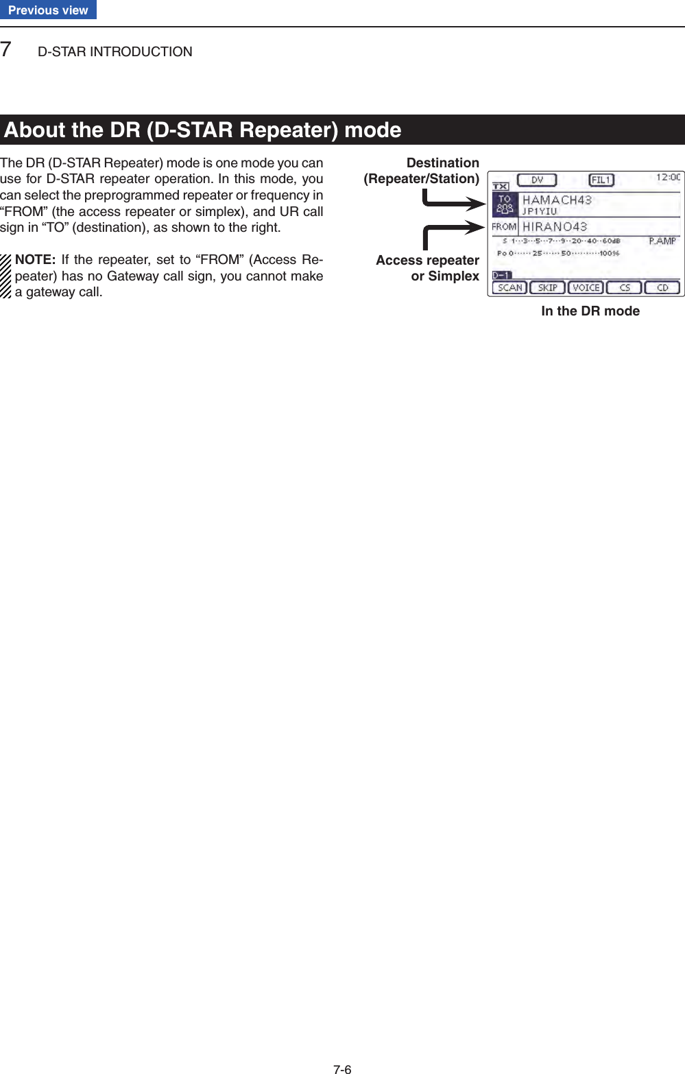
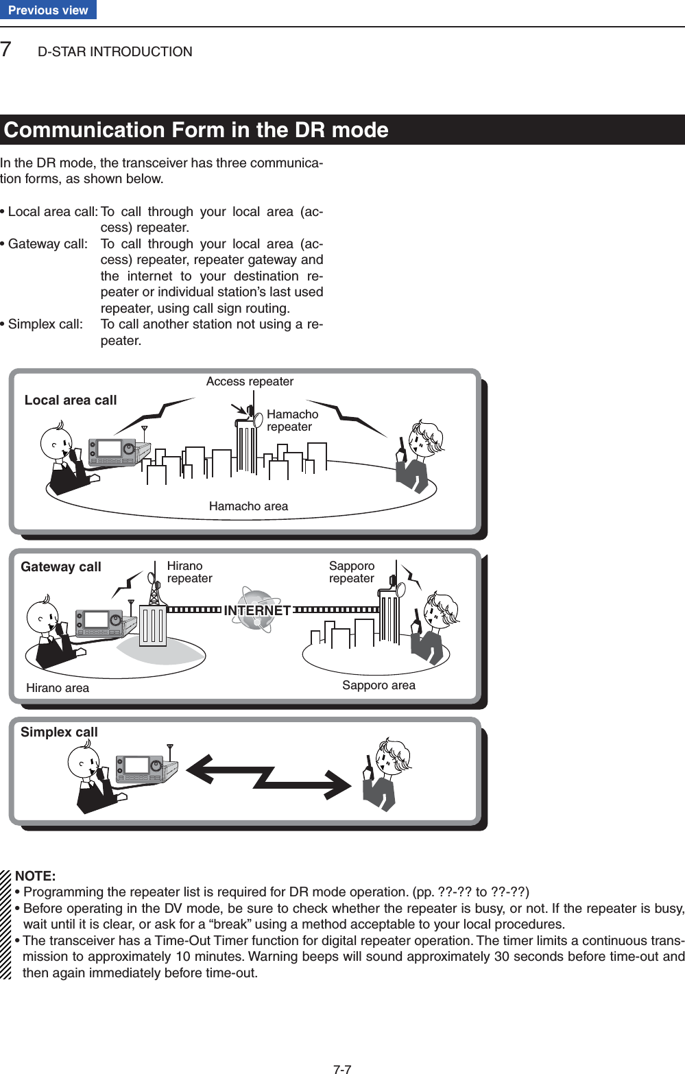
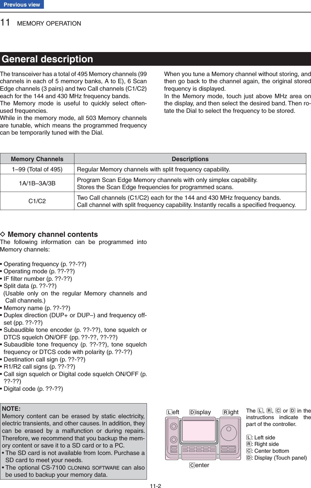
 to select a Memory bank that contains the channel you want to select. Rotate [M-CH]( eL) to select a Memory channel num-ber. • Rotate clockwise to select a higher Memory channel number; rotate counterclockwise to select a lower Mem-ory channel number. • All Memory channels, including blank channels, can be selected. • “BLANK” appears when no information has been pro-grammed into the Memory channel. (Blank channel) • You can do either step r or t fi rst. NOTE: When the PBT indicator lights green, or the RIT indicator lights orange, push [M-CH](L) to turn OFF the indicator fi rst, and then rotate it. Touch the Memory channel number indication to se- rlect the Memory mode. • “MEMO” and the Memory channel contents appear.Selecting in the Memory mode D Touch the Memory channel number indication once qor twice to select the Memory mode. (p. ??-??) Rotate [BANK]( wL) to select a Memory bank that contains the channel you want to select. Rotate [M-CH]( eL) to select a Memory channel num-ber. • Rotate clockwise to select a higher Memory channel number; rotate counterclockwise to select a lower Mem-ory channel number. • All Memory channels, including blank channels, can be selected. • “BLANK” appears when no content has been programmed into the Memory channel. (Blank channel) • Memory channels can also be selected using the micro-phone [UP]/[DN] keys. In such case, the blank channels are skipped.While in the VFO modeWhile in the Memory modeAppearsAppearsAppearsOuter: [BANK]Inner: [M-CH]Selecting a Memory channelThe L, R, C or D in the instructions indicate the part of the controller.L: Left sideR: Right sideC: Center bottomD: Display (Touch panel)Left RightCenterDisplay](https://usermanual.wiki/ICOM-orporated/339300/User-Guide-2000118-Page-91.png)
![11 MEMORY OPERATION11-4Previous viewTwo Call channels (C1/C2) are selectable in each of the 144 and 430 MHz frequency bands.Factory default frequencies and operating modes are programmed into the Call channels. Change these to suit your operating needs. (see page ??) Select qthe 144 or 430 MHz frequency band. (p. ??-??) Push wTUNER/CALL(L) to select the Call channel of the selected frequency band. • “CALL1” appears. • Rotate [M-CH] to select “CALL2.” Push eTUNER/CALL(L) again to return to the previous screen display.While in the Call channel modeAppearsTUNER/CALLSelecting a Call channel](https://usermanual.wiki/ICOM-orporated/339300/User-Guide-2000118-Page-92.png)
 or [M-CH](L) to select the Mem-ory channel to be programmed. • “BLANK” appears when no content has been programmed into the Memory channel. (Blank channel) Touch [MW]( rD) for 1 second to program the con-tents into the Memory channel.Programming in the Memory mode D Touch the Memory channel number indication once qor twice to select the Memory mode. (p. ??-??) Rotate [M-CH]( wL) to select the Memory channel to be programmed. • The contents of the Memory channel appear in the dis-play. • “BLANK” appears if the selected Memory channel is a blank channel.Set the desired contents into the Memory channel. e • When a blank channel is selected, touch just above MHz area on the display, and then select the desired band. Rotate the Dial to select the frequency. (p. ??) Touch [MW]( rD) for 1 second to program the con-tents into the Memory channel.Programming the Call channels DIt is convenient to program often-used frequencies into the Call channels for quick recall. Rotate [M-CH]( qL) to select a Call channel. • A capital “C” appears.Set the desired contents into the channel. w Touch [MW]( eD) for 1 second to program the con-tents into the Call channel.IMPORTANT!When a Call channel is selected by pushing TUNER/CALL(L), you cannot change the memory contents. How-ever, when a Call channel is selected using [M-CH] in the VFO or Memory mode, the memory contents can be changed.The 144 MHz frequency band can be programmed into the 144 “C1” or C2,” and the 430 MHz frequency band can be programmed into the 430 “C1” or C2.”While in the Memory mode[Example]:Programming 7.088 MHz/LSB into Memory channel 12 while in the VFO mode.[Example]:Programming 21.280 MHz/USB into Mem-ory channel 18 while in the Memory mode.Programming a Memory channel AppearsAppearsThe L, R, C or D in the instructions indicate the part of the controller.L: Left sideR: Right sideC: Center bottomD: Display (Touch panel)Left RightCenterDisplay](https://usermanual.wiki/ICOM-orporated/339300/User-Guide-2000118-Page-93.png)
. • The “MW” screen appears. Rotate [BANK]( tL) or [M-CH](L) to select the Mem-ory channel to be programmed. • “---.---.-- ------” appears when no content has been pro-grammed into the Memory channel. (Blank channel) Touch [MW]( yD) for 1 second to program the con-tents into the Memory channel. Check the programmed contents on the Memory umode. (p. ??-??)For your reference ✓The Memory channel contents, programmed in the DR mode, can also be copied to the VFO. (p. ??-??)The L, R, C or D in the instructions indicate the part of the controller.L: Left side, R: Right side, C: Center bottomD: Display (Touch panel)Set the desired contents.BlinksTouch [MW]Touch [MW] for 1 secondDRMENU[Example]:Programming “HIRANO43” in “FROM”/ “HAMACH43” in “TO” into Memory channel A-01.[BANK]/[M-CH]](https://usermanual.wiki/ICOM-orporated/339300/User-Guide-2000118-Page-94.png)
 to display the “MEMO” (Memory) screen. Rotate [BANK]( wL) to select the Memory bank (A to E) to be checked. Touch [LIST]( eD) to display the “MEMORY LIST” screen. • Touch [∫] or [√](D) to select the displayed page. • The Program Scan Edge Memory channels can be checked on any band screen. “MEMORY LIST”screen of Bank A.The L, R, C or D in the instructions indicate the part of the controller.L: Left sideR: Right sideC: Center bottomD: Display (Touch panel)Left RightCenterDisplayAccess repeater call signDestination call sign Checking the Memory contents pro- Dgrammed in the DR mode Push qDR one or more times to cancel the DR mode. Touch the Memory channel number indication once wor twice to select the Memory mode. (p. ??-??) • The access repeater call sign and the destination call sign appear. When the “M-2” (Menu 2) screen is selected, touch [CS](D) to display the call sign programmed in the selected channel.For your reference ✓“FROM” and “TO” names are automatically programmed as the Memory name.• The Memory name is not overwritten when the memo-ry contents are programmed into the preprogrammed channel.](https://usermanual.wiki/ICOM-orporated/339300/User-Guide-2000118-Page-95.png)
 or [M-CH](L) to select the Mem-ory channel to be cleared. Push eMENU (C) one or more times to select the “M-3” screen (Menu 3). Touch [MEMO]( rD). Touch [M-CL]( tD) for 1 second to clear the contents. • The programmed contents disappear. • “BLANK” appears.Touch [M-CL]for 1 second.Touch[MEMO].Clearing a Memory channelThe L, R, C or D in the instructions indicate the part of the controller.L: Left sideR: Right sideC: Center bottomD: Display (Touch panel)Left RightCenterDisplay](https://usermanual.wiki/ICOM-orporated/339300/User-Guide-2000118-Page-96.png)
 or [M-CH](L) to select the Mem-ory channel to be copied. • “BLANK” appears if the selected Memory channel is a blank channel. In this case nothing can be copied. Touch [V/M]( eD) for 1 second to copy the Memory channel contents into the VFO. Touch the Memory channel number indication to se- rlect the VFO mode. (p. ??-??)Copying in the VFO mode D In the VFO mode, select the Memory channel num- ➥ber to be copied. And then, touch [V/M] for 1 second to copy the Memory channel contents into the se-lected VFO. • “BLANK” appears if the selected Memory channel is a blank channel. In this case nothing can be copied.Touch [V/M]for 1 second.Touch [V/M].The Memorychannel contents are transferred into the selected VFO.( The display does not change.)Copying Memory contentsThe L, R, C or D in the instructions indicate the part of the controller.L: Left sideR: Right sideC: Center bottomD: Display (Touch panel)Left RightCenterDisplay](https://usermanual.wiki/ICOM-orporated/339300/User-Guide-2000118-Page-97.png)
![11 MEMORY OPERATION11-10Previous viewAll Memory channels, including Scan Edges and Call channels, can be tagged with alphanumeric names of up to 16 characters each.[EXAMPLE]: Programming a memory name into Mem-ory channel 99 of Bank A. Touch the Memory channel number indication once qor twice to select the Memory mode. (p. ??-??) Rotate [BANK] to select Bank A. w Rotate [M-CH] to select the Memory channel 99. e Push rMENU (C) one or more times to select the “M-3” screen (Menu 3). Touch [MEMO]( tD) to display the “MEMO” screen (Memory Menu). Touch [LIST]( yD) to display the “MEMORY LIST” screen. Push uQUICK (D), and then touch [Edit Name] to en-ter the “MEMORY NAME” screen (Memory name edit screen). • A cursor appears and blinks. • If the channel you selected is a blank channel, [Edit Name] does not appear. Touch the desired block one or more times to iselect the desired character or symbol.Selectable characters and symbolsA to Z, a to z, 0 to 9, ! # $ % & \ ? " ’ ` ^ + – ✱ ⁄ . , : ; = < > ( ) [ ] { } ¦ _ ¯ @ (space) • Touch “AB12” to toggle between the Alphabet input and Number input mode. • Touch [CLR](D) to delete the selected character, symbol or number. • Touch [SYMB](D) to open the Symbol character selec-tion window. • Touch “” to input a space.Memory name edit screenInput mode screenInput a spaceMove the cursorMove the cursorDelete a characterSelect an input modeEnterCancel editTouch [!"#] to open the Symbol character selec-tion window.Touch [MEMO]on the “M-3” screen.Touch [LIST]Touch[Edit Name].“MEMORY LIST”screen of Bank A.Push QUICKProgramming a Memory name Continued on the next page. ☞The L, R, C or D in the instructions indicate the part of the controller.L: Left sideR: Right sideC: Center bottomD: Display (Touch panel)Left RightCenterDisplay](https://usermanual.wiki/ICOM-orporated/339300/User-Guide-2000118-Page-98.png)
 to move the cursor backwards, or touch [](D) to move the cursor forwards.!0 Repeat steps i and o to program up to 16 char-acters memory name, and then touch [ENT](D) to save the name, and return to the “MEMORY LIST” screen.!1 Touch [](D) to return to the “MEMO” (Memory) screen. • Push MENU(C) to return to the “M-3” screen (Menu 3).After program-ming, touch [ENT]Touch [] to return to the “MEMO” screen.Memory name programming (Continued)](https://usermanual.wiki/ICOM-orporated/339300/User-Guide-2000118-Page-99.png)
![11 MEMORY OPERATION11-12Previous viewWhile in the memory mode, the programmed memory name can be displayed. Touch the Memory channel number indication once qor twice to select the Memory mode. (p. ??-??) Push wQUICK (D) to open the Quick Menu window.Touch [Name Display]. eTouch the desired Display type option. r • OFF: Displays only the frequency. • ON: Displays the memory name under the fre-quency. (Default)PushQUICK .Touch[Name Display].Touch “ON.”The memory name disappears.Selecting a Memory display typeThe L, R, C or D in the instructions indicate the part of the controller.L: Left sideR: Right sideC: Center bottomD: Display (Touch panel)Left RightCenterDisplay](https://usermanual.wiki/ICOM-orporated/339300/User-Guide-2000118-Page-100.png)
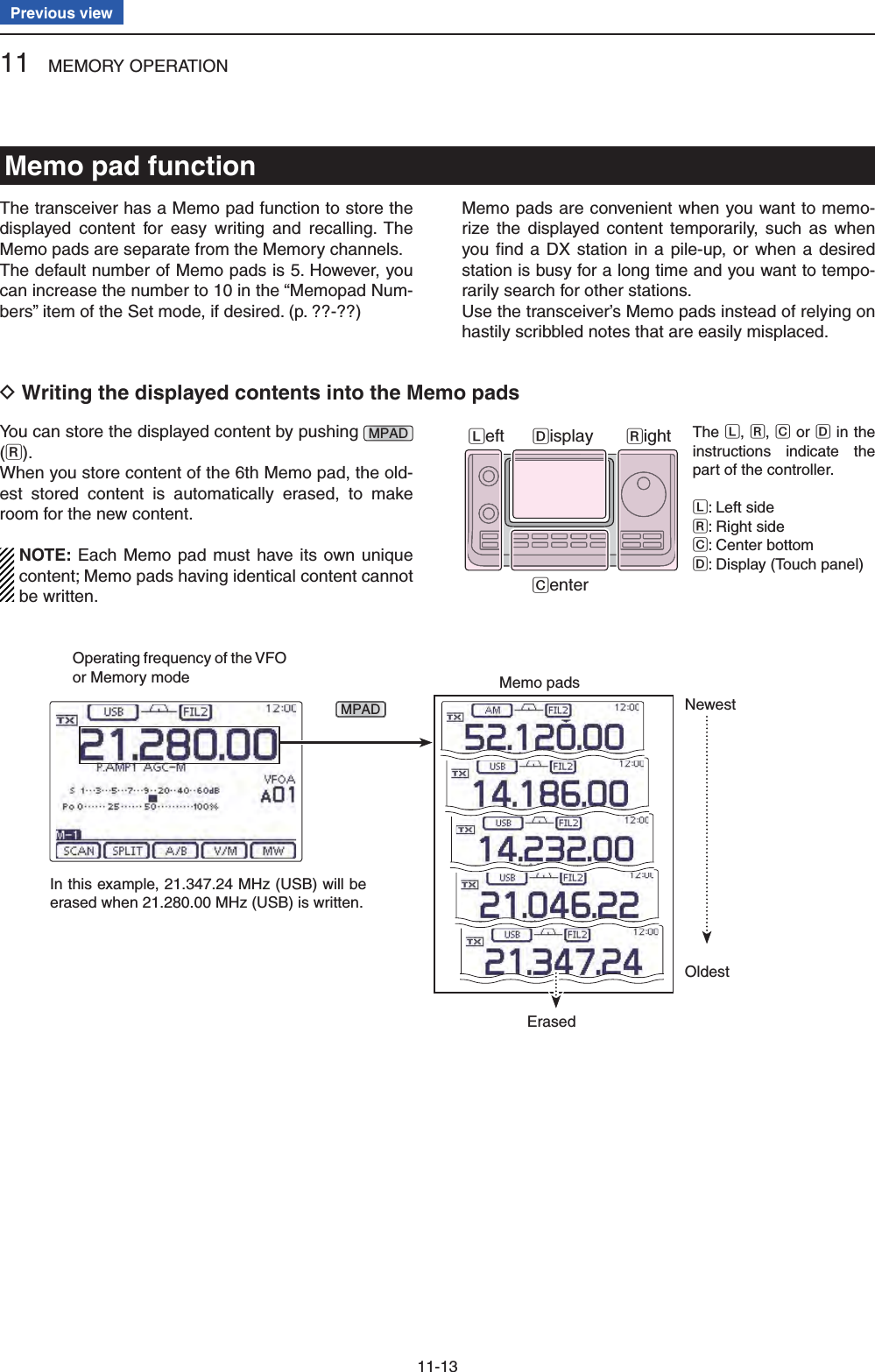
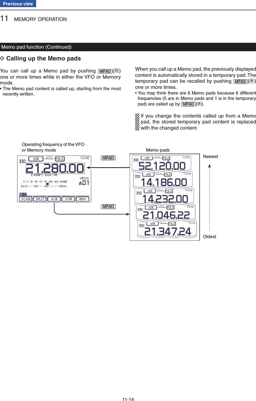
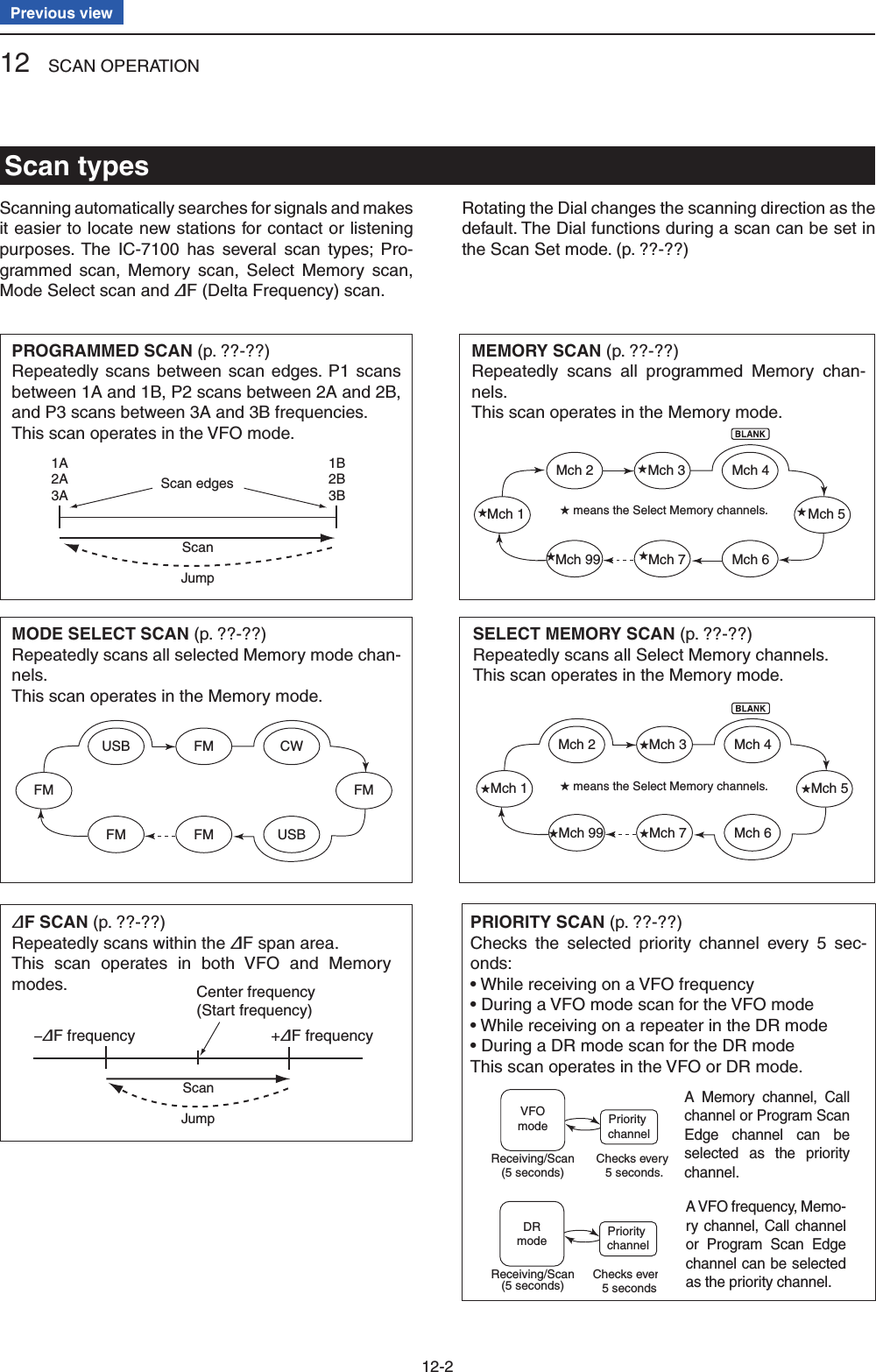
 to display the “SCAN” screen. Touch [SET]( eD) to display the “SCAN SET” screen. Touch the desired item. r • To go back the previous tree level, touch [](D), or MENU (C). Touch a desired option shown on the display. t • When you touch an option, it is automatically saved and goes back the previous tree level. • Push QUICK (C), and then touch “Default” to reset to the default setting, if desired. Push yMENU (C) to return to the “SCAN” screen.Touch [SCAN]Touch[SET]Touch a desired item.( Example: SCAN Resume)Touch a desired option.(Example: OFF)The L, R, C or D in the instructions indicate the part of the controller.L: Left sideR: Right sideC: Center bottomD: Display (Touch panel)Left RightCenterDisplay](https://usermanual.wiki/ICOM-orporated/339300/User-Guide-2000118-Page-106.png)
![12 SCAN OPERATION12-6Previous viewVoice Squelch Control function(Mode: SSB/AM/FM)This function is useful when you do not want unmodu-lated signals pausing or cancelling a scan. When the Voice Squelch Control (VSC) function is ON, the receiv-er checks received signals for voice components.The scan pauses, or is cancelled, if a received signal includes voice components, and the tone of the voice components changes within 1 second. See “Squelch status” as described on page ??-??.The scan resumes if the received signal includes no voice components, or the tone of the voice components does not change within 1 second. Select SSB, AM or FM as the operating mode. q Push wQUICK (D) to open the Quick Menu window.Touch [VSC]. eTouch the desired option. r • “ ” appears when the VSC function is ON. • When you touch an option, it is automatically saved and goes back the previous tree level.• The VSC function is usable in the phone modes (SSB, AM and FM).• The VSC function resumes the scan on unmodu-lated signals, regardless of whether the Scan Re-sume function is set to ON or OFF.QUICKTouch [VSC].Touch a desired option.(Example: ON)AppearsThe L, R, C or D in the instructions indicate the part of the controller.L: Left sideR: Right sideC: Center bottomD: Display (Touch panel)Left RightCenterDisplayNOTE: While listening to the radio with the VSC function ON, the audio may be interrupted. The mu-sic or a commercial, including narration or BGM, is not detected as an audio component. In this case, turn OFF the VSC function.](https://usermanual.wiki/ICOM-orporated/339300/User-Guide-2000118-Page-108.png)
![12 SCAN OPERATION12-7Previous viewMemory channels 1A–3A and 1B–3B are the Program Scan Edge channels. They are used to program the up-per and lower frequency edges for programmed scans. (p. ??-??)Factory default frequency and operating modes are programmed into the Scan Edge channels: 1A/1B are for HF, 2A/2B are for the 144 MHz, and 3A/3B are for the 430 MHz frequency bands, and you can reprogram it as desired.If both upper and lower band edges are programmed with the same frequency, a programmed scan can-not start.EXAMPLE: Programming 14.000.00 MHz into 2A and 14.360.00 MHz into 2B. Touch the Memory channel number indication once qor twice to select the VFO mode. (p. ??-??)Rotate [M-CH] w(L) to select scan edge 2A.Set 14.000.00 MHz as the lower frequency. e Push rMENU (C) one or more times to select the “M-1” (Menu 1) screen. Touch [MW]( tD) for 1 second to program 14.000.00 MHz into scan edge 2A. • Three beeps sound when the programming is complete.Rotate [M-CH] y(L) to select scan edge 2B.Set 14.360.00 MHz as the upper frequency. u Touch [MW] for 1 second to program 14.360.00 MHz iinto scan edge 2B. • Three beeps sound when the programming is complete. If 2A/2B is selected as the scanning range when a oprogrammed scan is started, it will search for signals between 14.000.00 MHz and 14.360.00 MHz. (p. ??-??)[M-CH]MENUTouch [MW]for 1 secondProgramming 14.000.00 MHz/USB into 2A.Programming 14.360.00 MHz/USB into 2B.Scan edge programmingThe L, R, C or D in the instructions indicate the part of the controller.L: Left sideR: Right sideC: Center bottomD: Display (Touch panel)Left RightCenterDisplay](https://usermanual.wiki/ICOM-orporated/339300/User-Guide-2000118-Page-109.png)
 to display the “SCAN” screen.Set [RF/SQL] open or closed. y • The scan performance differs, depending on the squelch setting when the scan was started. See page ??-?? for details. • If the [RF/SQL] control function is set to “AUTO,” the squelch is always open in the SSB, CW and RTTY modes. (pp. ??-??, ??-??) Touch [PROG]( uD) for 1 second, and then touch the desired scan range between “P1,” “P2” and “P3.” • The scan searches between programmed scan channels 1A–1B (P1), 2A–2B (P2) or 3A–3B (P3). • Example: P2: 14.000.00–14.360.00Touch [PROG]( iD) to start the programmed scan. • The MHz and kHz decimal points, and the selected scan range display blink while scanning. • If “Up/Down” is selected as the “MAIN DIAL (SCAN)” op-tion in the Scan Set mode, rotating the Dial changes the scanning direction. (p. ??-??) When the scan detects a signal, the scan stops, opauses or ignores it, depending on the Scan Resume function, the VSC function or the squelch status.!0 Push [PROG](D) to cancel the scan.While Programmed scanningTouch [SCAN]Touch [PROG]for 1 second.Touch the de-sired scan range (Exam-ple: P2)Programmed scan (VFO mode)The L, R, C or D in the instructions indicate the part of the controller.L: Left sideR: Right sideC: Center bottomD: Display (Touch panel)Left RightCenterDisplay](https://usermanual.wiki/ICOM-orporated/339300/User-Guide-2000118-Page-110.png)
 to switch the scan function between a programmed scan and a Fine programmed scan.Touch [PROG]( eD) to cancel the scan.While Fine programmed scanningWhile Programmed scanningTouch [FINE].Touch [FINE].The L, R, C or D in the instructions indicate the part of the controller.L: Left sideR: Right sideC: Center bottomD: Display (Touch panel)Left RightCenterDisplay](https://usermanual.wiki/ICOM-orporated/339300/User-Guide-2000118-Page-111.png)
 to display the “SCAN” screen.Set [RF/SQL] open or closed. r • The scan performance differs, depending on the squelch setting when the scan was started. See page 146 for de-tails. • If the [RF/SQL] control function is set to “AUTO,” the squelch is always open in the SSB, CW and RTTY modes. (pp. ??-??, ??-??)Touch [MEMO]( tD) to start the Memory scan. • The MHz and kHz decimal points, and “MEMO SCAN” blink while scanning. • If “Up/Down” is selected as the “MAIN DIAL (SCAN)” op-tion in the Scan Set mode, rotating the Dial changes the scanning direction. (p. ??)Touch [MEMO]( yD) to cancel the scan.While Memory scanningTouch [SCAN]Touch [MEMO]Memory scan (Memory mode)The L, R, C or D in the instructions indicate the part of the controller.L: Left sideR: Right sideC: Center bottomD: Display (Touch panel)Left RightCenterDisplay](https://usermanual.wiki/ICOM-orporated/339300/User-Guide-2000118-Page-112.png)
 for 1 second, and then touch “MODE-SEL” to start the Mode Select scan. • The MHz and kHz decimal points, and “MODE-SEL SCAN” blink while scanning. • If “Up/Down” is selected as the “MAIN DIAL (SCAN)” op-tion in the Scan Set mode, rotating the Dial changes the scanning direction. (p. ??-??) To change the operating mode while scanning, touch ethe mode icon to display the Mode selection screen, and then touch the desired operating mode.Push [MEMO]( rD) to cancel the scan.While Mode Select scanningTouch [MEMO]for 1 secondTouch“MODE-SEL.”Touch the mode icon, and then touch the de-sired operating modeMemory scan (Memory mode) (Continued)The L, R, C or D in the instructions indicate the part of the controller.L: Left sideR: Right sideC: Center bottomD: Display (Touch panel)Left RightCenterDisplay](https://usermanual.wiki/ICOM-orporated/339300/User-Guide-2000118-Page-113.png)
 for 1 second, and then touch “SEL-MEMO” to start the Select Memory scan. • The MHz and kHz decimal points, and “SEL–MEMO SCAN” blink while scanning. • If “Up/Down” is selected as the “MAIN DIAL (SCAN)” op-tion in the Scan Set mode, rotating the Dial changes the scanning direction. (p. ??-??)Push [MEMO]( eD) to cancel the scan.While Select Memory scanningTouch [MEMO]for 1 second.Touch “SEL-MEMO.”AppearsMemory scan (Memory mode) (Continued)The L, R, C or D in the instructions indicate the part of the controller.L: Left sideR: Right sideC: Center bottomD: Display (Touch panel)Left RightCenterDisplay](https://usermanual.wiki/ICOM-orporated/339300/User-Guide-2000118-Page-114.png)
![12 SCAN OPERATION12-13Previous viewMemory scan (Memory mode) (Continued)All Memory channels can be set as Select Memory chan-nels, except for the Scan Edge and Call channels. When the “SCAN” screen or the “MEMO” screen ➥(Memory Menu) is displayed, touch [SEL] to set or cancel the displayed Memory channel as a Select Memory channel. • “” appears when the channel is set as a Select Memory channel. • An error beep sounds when the displayed Memory chan-nel is a blank channel. • Touching [SEL] for 1 second displays “SELECT ALL Clear?.” Touch [YES](F-4) to clear all Select Memory channel settings.Setting/Cancelling Select Memory channels D“SCAN” screenWhen the channel is set as a Select Memory channel.“SELECT ALL Clear?” screenAfter touching [SEL] for 1 second to clear all Select Memory channel settings.AppearsThe L, R, C or D in the instructions indicate the part of the controller.L: Left sideR: Right sideC: Center bottomD: Display (Touch panel)Left RightCenterDisplay](https://usermanual.wiki/ICOM-orporated/339300/User-Guide-2000118-Page-115.png)
 to display the “SCAN” screen.Set [RF/SQL] open or closed. r • The scan performance differs, depending on the squelch setting when the scan was started. See page 146 for de-tails. • If the [RF/SQL] control function is set to “AUTO,” the squelch is always open in the SSB, CW and RTTY modes. (pp. ??-??, ??-??) Touch [SPAN]( tD) one or more times to select the desired ∂F span width. • ±5 kHz, ±10 kHz, ±20 kHz, ±50 kHz, ±100 kHz, ±500 kHz and ±1 MHz are selectable.Set the center frequency of the y∂F scan. • In the VFO mode, rotate the Dial to set the center fre-quency. • In the memory mode, rotate [M-CH] (L) to select the desired Memory channel whose frequency will be the center frequency.Touch [ u∂F](D) to start the ∂F scan. • “∂F SCAN,” the MHz and kHz decimal points blink while scanning. • If “Up/Down” is selected as the “MAIN DIAL (SCAN)” op-tion in the Scan Set mode, rotating the Dial changes the scanning direction. (p. ??-??) When the scan detects a signal, the scan stops, ipauses or ignores it, depending on the Scan Re-sume function, VSC function or the squelch status.Touch [ o∂F](D) again to cancel the ∂F scan.While ∂F scanning (VFO mode)Set the center frequencyTouch[SCAN]Touch [SPAN] one or more times to select the ∂F span width.∂F scan and Fine ∂F scan (VFO mode/Memory mode)Rotate the Dial (VFO mode)Rotate the [M-CH] (Memory mode)The L, R, C or D in the instructions indicate the part of the controller.L: Left sideR: Right sideC: Center bottomD: Display (Touch panel)Left RightCenterDisplay](https://usermanual.wiki/ICOM-orporated/339300/User-Guide-2000118-Page-116.png)
 to switch the scan function between ∂F scan and Fine ∂F scan.Touch [ e∂F](D) to cancel the scan.While Fine ∂F scanningWhile ∂F scanningTouch [FINE]Touch [FINE]∂F scan and Fine ∂F scan (VFO mode/Memory mode) (Continued)The L, R, C or D in the instructions indicate the part of the controller.L: Left sideR: Right sideC: Center bottomD: Display (Touch panel)Left RightCenterDisplay](https://usermanual.wiki/ICOM-orporated/339300/User-Guide-2000118-Page-117.png)
![12 SCAN OPERATION12-16Previous viewThe receive frequency and the operating mode settingSet the priority channel (Example: A05)QUICK[BANK]/[M-CH]Select the VFO modeSelect theMemory modeTouch“PRIO Watch ON”While Priority scanningVFO frequency and a priority channelChecks the selected priority channel every 5 seconds, while receiving on a VFO frequency. Touch the Memory channel number indication once qor twice to select the VFO mode. (p. ??-??) Set the receive frequency and the operating mode. w(p. ??-??) Touch the Memory channel number indication to se- elect the Memory mode. (p. ??-??) Rotate [BANK] or [M-CH] r(L) to set the priority channel. • Memory channel, Call channel or Program Scan Edge chan-nel can be selected as the priority channel. Push tQUICK (D) to open the Quick Menu window.Touch “PRIO Watch ON” to start the Priority scan. y • The VFO mode is automatically selected, and PRIO ap-pears. • To cancel the Priority scan, touch “PRIO Watch OFF” in the Quick Menu window.When a signal is received on the priority channelThe Priority channel is automatically selected, and PRIO blinks on the screen.• The scan pause timer and resume settings are the same as for a normal scan.Priority scan au-tomatically paus-es.NOTE:When the VFO mode is selected, you can normally operate the transceiver; the operating frequency set-ting, the scanning operation and so on.The L, R, C or D in the instructions indicate the part of the controller.L: Left sideR: Right sideC: Center bottomD: Display (Touch panel)Left RightCenterDisplayTo start the Programmed scan during the Priority scan, touch [SCAN] in the “M-1” (Menu 1) screen, and then touch [PROG].](https://usermanual.wiki/ICOM-orporated/339300/User-Guide-2000118-Page-118.png)
![12 SCAN OPERATION12-17Previous viewThe receive frequency and the operating mode setting[BANK]/[M-CH]DRWhen the VFO frequency is set as the priority channelSelect the repeater to receive(Example: Hirano43)Select the DR modeTouch“PRIO Watch ON”Appears while the priority scanningSet the receive frequency in the VFO mode.Checks the selected priority channel every 5 seconds, while receiving a repeater in the DR mode.Set the priority channel1. • Using the VFO frequency q Touch the Memory channel number indication once or twice to select the VFO mode. (p. ??-??) w Set the receive frequency and the operating mode. (p. ??-??) • Using the Memory/Call/Program Scan Edge channel q Touch the Memory channel number indication once or twice to select the Memory mode. (p. ??-??) w Rotate [BANK] or [M-CH] (L) to set the priority channel. • Memory channel, Call channel or Program Scan Edge channel can be selected as the priority channel.Select the repeater in the DR mode2. q Push DR(C) to select the DR mode. (p. ??-??) w Touch “FROM” (Access repeater), if “FROM” is not selected. e Rotate the Dial to select the desired repeater. • You can select a repeater in the “FROM SELECT” screen that is displayed after touching the repeater name on “FROM.”Start the Priority scan3. q Push QUICK (D) to open the Quick Menu win-dow. w Touch “PRIO Watch ON” to start the Priority scan. • The DR mode screen is automatically selected, and PRIO appears. • To cancel the Priority scan, touch “PRIO Watch OFF” in the Quick Menu window.DR mode and a priority channelThe L, R, C or D in the instructions indicate the part of the controller.L: Left sideR: Right sideC: Center bottomD: Display (Touch panel)Left RightCenterDisplay](https://usermanual.wiki/ICOM-orporated/339300/User-Guide-2000118-Page-119.png)
![12 SCAN OPERATION12-18Previous viewDR mode and a priority channel (Continued)NOTE:When the DR mode screen is displayed, you can normally use the DR mode; “FROM” (Access repeater)/“TO” (Destination) selection, the DR mode scanning and so on.To start the DR mode scan, touch [SCAN] in the “D-1” screen.When a signal is received on the priority channelThe Priority channel is automatically selected, and PRIO blinks on the screen.• The scan pause timer and resume settings are the same as for a normal scan.Priority scan au-tomatically paus-es.](https://usermanual.wiki/ICOM-orporated/339300/User-Guide-2000118-Page-120.png)
![13 USING AN SD CARD13-4Previous viewTurn OFF the transceiver. q Insert the card into the slot until it locks in place, and wmakes a ‘click’ sound. • “ ” appears when the SD card is inserted. • “” and “ ” alternately blink while accessing the SD card.NOTE: Before inserting, be sure to check the card direction.If the card is forcibly or inversely inserted, it will dam-age the card and/or the slot.Inserting the SD cardTerminalsfacing down Cut corner sideFront panelSD cardAppears●wqqFormatting the SD card D• If you use a brand new SD card, format it, by doing the following steps.• Formatting a card erases all its data. Before for-matting any programmed card, make a backup fi le onto your PC. Turn OFF the transceiver, and then insert the card qinto the slot.Turn ON the transceiver. w • “ ” appears when the SD card is inserted.Push eSET(C) to enter the Set mode. Touch the “SD Card” Set mode. r • If the specifi ed item is not displayed, touch [∫] or [√](D) one or more times to select the page. Touch the “Format” item. t • The confi rmation screen “Format OK?” appears. Touch [YES]( yD). • The formatting starts and the display shows the format-ting progress. • After formatting ends, the display automatically returns to the screen displayed before touching [YES](D).The L, R, C or D in the instructions indicate the part of the controller.L: Left sideR: Right sideC: Center bottomD: Display (Touch panel)Left RightCenterDisplay](https://usermanual.wiki/ICOM-orporated/339300/User-Guide-2000118-Page-124.png)
![13 USING AN SD CARD13-5Previous viewTurn OFF the power. q Push in the SD card until a click sounds, and then wcarefully pull it out.Removing the SD card Removing the SD card while the trans- Dceiver’s power is ONPush qSET(C) to enter the Set mode. Touch the “SD Card” Set mode. w • If the specifi ed item is not displayed, touch [∫] or [√](D) one or more times to select the page. Touch the “Unmount” item. e • The confi rmation screen “Unmount OK?” appears. Touch [YES]( rD). • When the unmounting is completed, “Unmount is com-pleted.” is displayed, then the display automatically re-turns to the screen displayed before touching [YES](D). Push in the SD card until a click sounds, and then tcarefully pull it out.PushPull out●wqqThe L, R, C or D in the instructions indicate the part of the controller.L: Left sideR: Right sideC: Center bottomD: Display (Touch panel)Left RightCenterDisplayFront panel](https://usermanual.wiki/ICOM-orporated/339300/User-Guide-2000118-Page-125.png)
![13 USING AN SD CARD13-6Previous viewMemory channels, Set mode item settings, and repeat-er lists can be saved on the SD card.Saving data settings on the SD card allows you to eas-ily restore the transceiver to its previous settings, even if an All reset is performed.For your information ✓Data settings are saved in the “icf” fi le format that is used in the CS-7100 cloning software.The saved data on the SD card can be copied onto a PC and edited by the cloning software. Data settings can be saved as a new fi le or to overwrite an older fi le.Saved as a new fi lePush qSET(C) to enter the Set mode. Touch the “Save Setting” item of the “SD Card” Set wmode. (SD Card > Save Setting) • If the specifi ed item is not displayed, touch [∫] or [√](D) one or more times to select the page. Touch “<<New File>>.” e • The “FILE NAME” screen appears. • The fi le name is automatically named in the following manner; Setyyyymmdd_xx (yyyy: Year, mm: month, dd: day, xx: serial number)Example: If a second fi le is saved on March 1, 2013, the fi le is named “Set20130301_02.” • If you want to change the fi le name, see “Save with a dif-ferent fi le name” (p. ??-??).Touch [ENT]( rD) to save the fi le name. • The confi rmation screen “Save fi le?” appears. Touch [YES]( tD) to save. • While saving, a progress bar is displayed, then the “SD CARD” screen is displayed after the save is completed. Push ySET(C) to exit the Set mode.Saving the setting data onto an SD card●wqqThe L, R, C or D in the instructions indicate the part of the controller.L: Left sideR: Right sideC: Center bottomD: Display (Touch panel)Left RightCenterDisplayOverwriting a fi le(Example: Overwriting the “Set20121210_01”) ➥Select the desired fi le to be overwritten in step e as described on page ??-??. (Example: Selecting “Set20121210_01”)](https://usermanual.wiki/ICOM-orporated/339300/User-Guide-2000118-Page-126.png)
![13 USING AN SD CARD13-7Previous viewSaving with a different fi le namePush qSET(C) to enter the Set mode. Touch the “Save Setting” item of the “SD Card” Set wmode. (SD Card > Save Setting) • If the specifi ed item is not displayed, touch [∫] or [√](D) one or more times to select the page. Touch “<<New File>>.” e • The “FILE NAME” screen appears. Touch [CLR]( rD) to delete the previously programmed character. • Touch [CLR](D) to delete the selected character, symbol or number. When the cursor does not select a character, the previ-ous character is deleted. If [CLR](D) is continuously touched, all the characters are deleted. Touch the desired block one or more times to tselect the desired character or symbol.Selectable characters and symbolsA to Z, a to z, 0 to 9, ! # $ % & \ ? " ’ ` ^ + – ✱ ⁄ . , : ; = < > ( ) [ ] { } ¦ _ ¯ @ (space) • Touch “AB12” to toggle between the Alphabet input and Number input mode. • Touch [CLR](D) to delete the selected character, symbol or number. • Touch [SYMB](D) to open the Symbol character selec-tion window. • Touch “” to input a space. Touch [ y](D) to move the cursor backwards, or touch [](D) to move the cursor forwards. Repeat steps ut and y to program up to 14 charac-ters name. • Example: MY DATATouch [ENT]( iD) to save the name. • The confi rmation screen “Save fi le?” appears. Touch [YES]( yD) to save. • While saving, a progress bar is displayed, then the “SD CARD” screen is displayed after the save is completed. Push uSET(C) to exit the Set mode.The L, R, C or D in the instructions indicate the part of the controller.L: Left sideR: Right sideC: Center bottomD: Display (Touch panel)Left RightCenterDisplayTouch [!"#] to open the Symbol char-acter selection window.After program-ming, touch [ENT]In the “Save Setting” screen, touch “<<New File>>”](https://usermanual.wiki/ICOM-orporated/339300/User-Guide-2000118-Page-127.png)
![13 USING AN SD CARD13-8Previous viewThe saved memory channels, Set mode item settings and repeater lists can be copied to the transceiver.This function is convenient when copying the saved data, such as memory channels, or repeater lists, to another IC-7100 and then operating with the same data.Saving the current data is recommended before load-ing other data in the transceiver.(Example: Loading all the data in the “Set20130301_01” fi le)Push qSET(C) to enter the Set mode. Touch the “Load Setting” item of the “SD Card” Set wmode. (SD Card > Load Setting) • If the specifi ed item is not displayed, touch [∫] or [√](D) one or more times to select the page. Touch the desired fi le to be loaded. e (Example: Selecting “Set20130301_01”) • The LOAD FILE screen appears. Touch the desired loading roption, as shown below. • ALL: Loads all memory channels, item settings in the menu list and the repeater list into the transceiver. • Select: Loads all memory channels, Set mode item settings and the repeater list into the transceiver. “MY call signs” and “REF Adjust” settings can be se-lected to be loaded. • Repeater List Only: Loads only the repeater list into the transceiver. The “Keep 'SKIP' settings in Repeater List?” appears. tTouch [YES], [NO] or [Cancel](D). • When [YES](D) is touched, the skip settings of the re-peater list are retained. (p. ??-??) • When [NO](D) is touched, the skip settings of the re-peater list are not retained. (p. ??-??) • When [Cancel](D) is touched, returns to the LOAD FILE screen. • When [YES] or [NO](D) is touched, “Load fi le?” ap-pears.To update the repeater list, click here!Loading the saved data fi les that are on the SD cardIn the “SD Card” screen, touch “Load Setting.”The L, R, C or D in the instructions indicate the part of the controller.L: Left sideR: Right sideC: Center bottomD: Display (Touch panel)Left RightCenterDisplayContinued on the next page ☞](https://usermanual.wiki/ICOM-orporated/339300/User-Guide-2000118-Page-128.png)
 to start the fi le check. • While checking the fi le, “CHECKING FILE” and a prog-ress bar are displayed.After checking, settings data loading ubegins. • While loading, “LOADING” and a progress bar are dis-played.After loading iends, “COMPLETED!” appears. To complete the loading, reboot the transceiver.Loading the saved settings fi le that are on the SD card (Continued)Appears only when “ALL” or “Select”* is selected in the LOAD FILE screen, * If “Select” is selected, only when the “REF Adjust” check box is checked.The L, R, C or D in the instructions indicate the part of the controller.L: Left sideR: Right sideC: Center bottomD: Display (Touch panel)Left RightCenterDisplay](https://usermanual.wiki/ICOM-orporated/339300/User-Guide-2000118-Page-129.png)
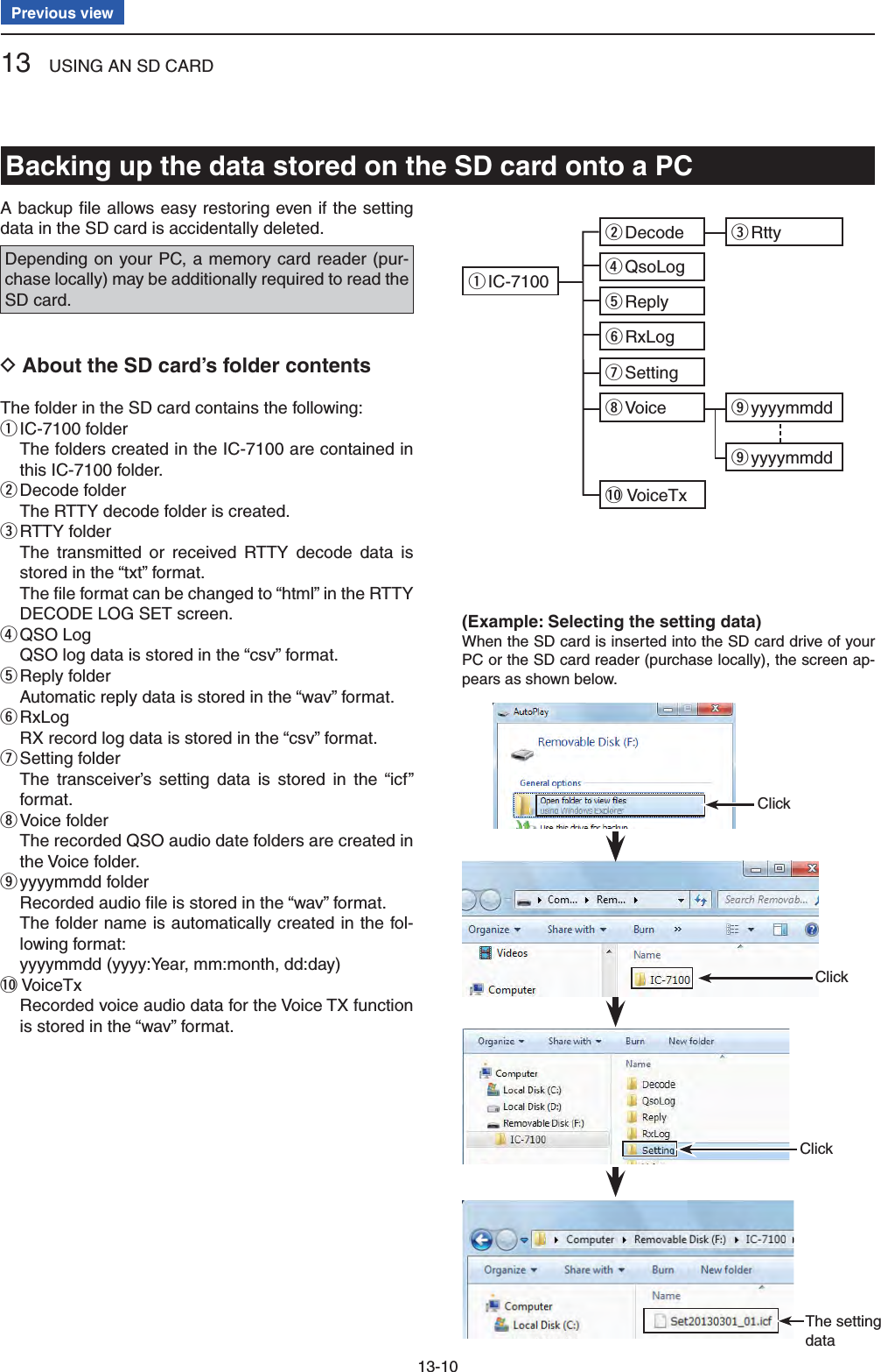
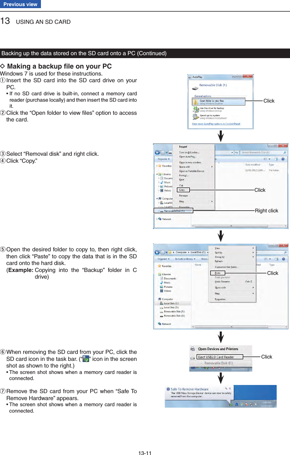
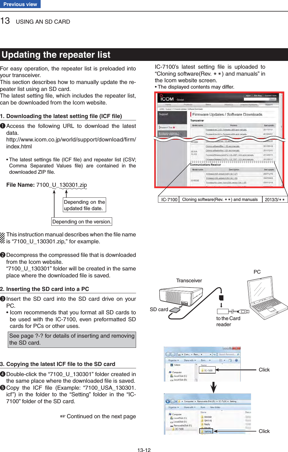
![13 USING AN SD CARD13-13Previous viewInserting the SD card4. y Remove the SD card from your PC, and insert the card into the transceiver’s slot.See page ??-?? for details of inserting the SD card into the transceiver.Saving the current data is recommended before loading other data into the transceiver.Updating the repeater list5. u Push SET(C) to enter the Set mode.i Touch the “Load Setting” item of the “SD Card” Set mode. (SD Card > Load Setting) • If the specifi ed item is not displayed, touch [∫] or [√](D) one or more times to select the page.o Touch the ICF fi le to be loaded. (Example: Selecting “7100_USA_130301.icf”) • The LOAD FILE screen appears.!0 Touch “Repeater List Only.” • The “Keep 'SKIP' settings in Repeater List?” appears. • Loads only the repeater list into the transceiver.Continued on the next page ☞Updating the repeater list (Continued)Select the fi le to be loaded●wqqSD cardTransceiverfrom the Card readerPCThe L, R, C or D in the instructions indicate the part of the controller.L: Left sideR: Right sideC: Center bottomD: Display (Touch panel)Left RightCenterDisplay](https://usermanual.wiki/ICOM-orporated/339300/User-Guide-2000118-Page-133.png)
![13 USING AN SD CARD13-14Previous view!1 Touch [YES], [NO] or [Cancel](D). • When [YES](D) is touched, the skip settings of the re-peater list are retained. (p. ??-??) • When [NO](D) is touched, the skip settings of the re-peater list are not retained. (p. ??-??) • When [Cancel](D) is touched, returns to the LOAD FILE screen. • When [YES] or [NO](D) is touched, “Load fi le?” ap-pears.!2 Touch [YES](D) to start the fi le check. • While checking the fi le, “CHECKING FILE” and a prog-ress bar are displayed.!3 After checking, settings data loading begins. • While loading, “LOADING” and a progress bar are dis-played.!4 After loading ends, “COMPLETED!” appears. To complete the loading, reboot the transceiver.Repeater list updating is complete!Updating the repeater list (Continued)The L, R, C or D in the instructions indicate the part of the controller.L: Left sideR: Right sideC: Center bottomD: Display (Touch panel)Left RightCenterDisplay](https://usermanual.wiki/ICOM-orporated/339300/User-Guide-2000118-Page-134.png)

![14-1Section 14 VOICE MEMORY FUNCTIONPrevious viewRecording a QSO audio ........................................................14-2To start recording D ..................................................................14-2To stop recording D ...................................................................14-2Changing the recording mode .............................................14-3Playing back the recorded audio .........................................14-4Operation while playing back ...............................................14-5Fast forward while playing D .....................................................14-5Rewind while playing D .............................................................14-5Pause while playing D ...............................................................14-5Playing the previous fi le D.........................................................14-5Playing the next fi le D ...............................................................14-5Moving to the beginning of the previous fi le D ..........................14-5Moving to the beginning of the next fi le D .................................14-5VOICE PLAYER screen D’s descriptions ..................................14-5Changing the skip time .........................................................14-6Deleting the recorded contents (audio) ...............................14-7Deleting the folder .................................................................14-8Continue to record even if no signals are received ...........14-9Record the transmit and receive audio into the same fi le .14-10Start to record when the [PTT] switch is pushed ...............14-11Viewing the folder information .............................................14-12Viewing the fi le information ..................................................14-13Viewing the SD card’s free space and recordable time .....14-15Playing back the voice memory data on a PC ....................14-16](https://usermanual.wiki/ICOM-orporated/339300/User-Guide-2000118-Page-136.png)
 one or more times to select the desired page. • The transceiver displays “Recording started” and auto-matically exits the Quick Menu screen. • “” appears while the recording is paused. • “” appears and “ ” and “ ” alternately blink while record-ing. • Recording is continuous until you manually stop record-ing, or the card becomes full. • If the recording fi le’s content reaches 2GB, the transceiv-er automatically creates a new fi le, and continues record-ing.NOTE: Once recording has started, it will continue, even if the transceiver is rebooted.Recording a QSO audioQUICKWhile recordingWhile pausingTouch “<<REC Start>>”The L, R, C or D in the instructions indicate the part of the controller.L: Left sideR: Right sideC: Center bottomD: Display (Touch panel)Left RightCenterDisplayConvenient! ✓When the PTT Automatic Recording function is set to ON, the recording automatically starts when [PTT] is pushed. (p. ??-??)( Voice Memo > QSO Recorder > Recorder Set > PTT Auto REC)To stop recording D Push qQUICK(C) to open the Quick Menu screen. Touch “<<REC Stop>>” to stop voice recording. w • Touch [√](D) one or more times to select the desired page. • The transceiver displays “Recording stopped,” and auto-matically exits the Quick Menu screen.Touch“<<REC Stop>>”](https://usermanual.wiki/ICOM-orporated/339300/User-Guide-2000118-Page-137.png)
![14 VOICE MEMORY FUNCTION14-3Previous viewYou can change the recording mode in the Set mode to record only the received audio.The default setting is “TX&RX” (Both transmit and receive signals are recorded).Push qSET(C) to enter the Set mode. Touch the “REC Mode” item of the “Voice Memo” Set wmode. ( Voice Memo > QSO Recorder > Recorder Set > REC Mode) • If the specifi ed item is not displayed, touch [∫] or [√](D) one or more times to select the page. Touch “RX Only” to esave, and return to the previous screen. Push rSET(C) to exit the Set mode.Changing the recording modeSETTouch“Voice Memo.”Touch“Recorder Set.”Touch“REC Mode.”Touch“RX Only.”Touch“QSO Recorder.”](https://usermanual.wiki/ICOM-orporated/339300/User-Guide-2000118-Page-138.png)
![14 VOICE MEMORY FUNCTION14-4Previous viewPush qSET(C) to enter the Set mode. Touch the “Play Files” item of the “Voice Memo” Set wmode. ( Voice Memo > QSO Recorder > Play Files) • If the specifi ed item is not displayed, touch [∫] or [√](D) one or more times to select the page. • The folder list is displayed. (The folders are automatically made when the recording starts.) • The folder name is formatted yyyymmdd (y: year, m: month, d: day.) Touch the folder that contains the fi le you want to eplay. • The fi le list is displayed. • The fi le name is formatted yyyy/mm/dd hh:mm:ss (y: year, m: month, d: day, hh: hour, mm: minute, ss: second.) Touch the fi le that you want to play. r • The VOICE PLAYER screen is displayed, and the fi le starts to playback. Touch [ t](D) or push MENU(C) to stop the play-back, and return to the fi le list screen.Playing back the recorded audioSETTouch the fold-er that contains the fi le you want to play.Touch the fi le that you want to play.Touch“Voice Memo.”Touch“QSO Recorder.”Touch“Play Files.”While playing back](https://usermanual.wiki/ICOM-orporated/339300/User-Guide-2000118-Page-139.png)
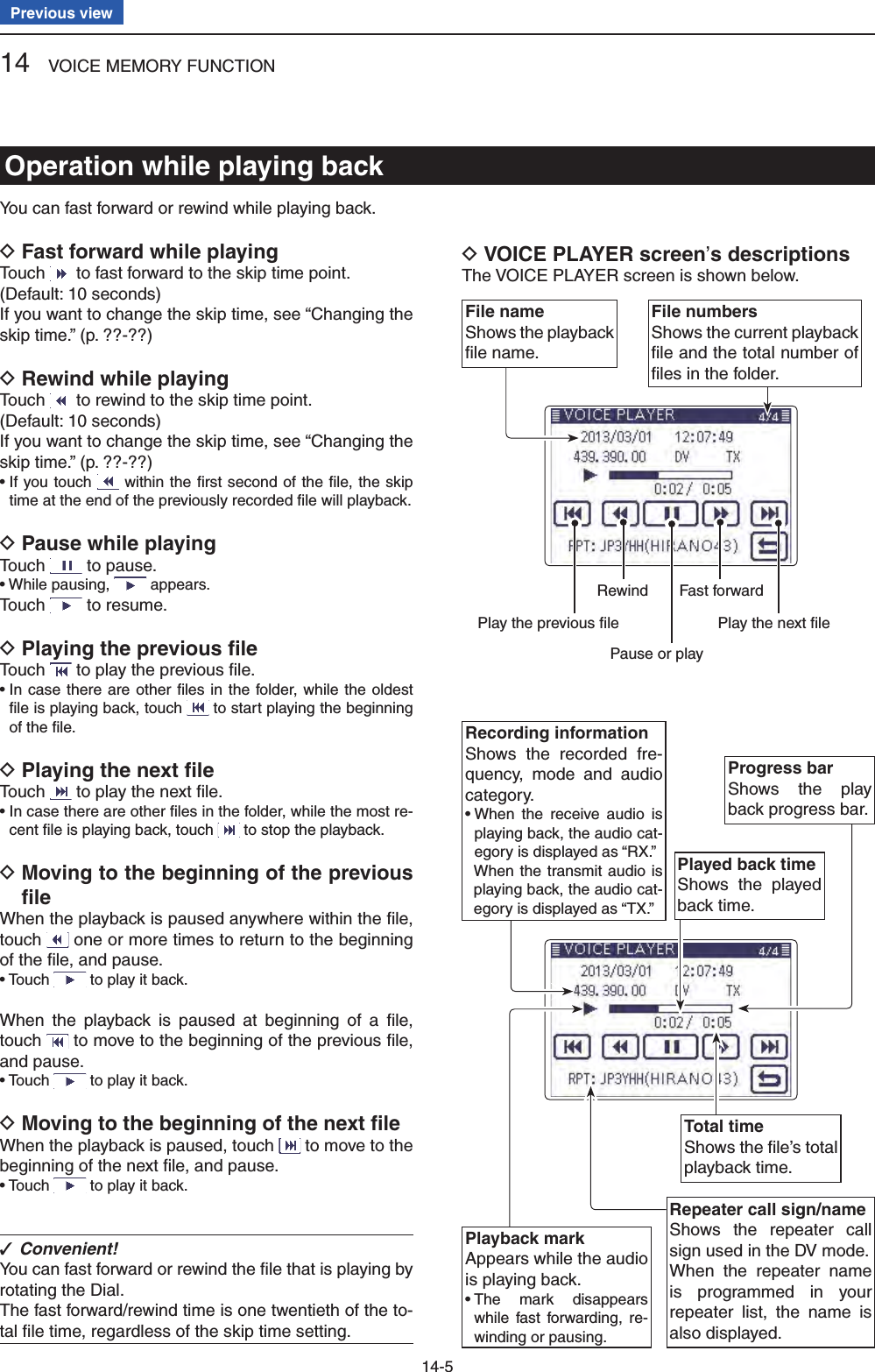
![14 VOICE MEMORY FUNCTION14-6Previous viewYou can change the fast forward and rewind skip time while playing.Push qSET(C) to enter the Set mode. Touch the “Skip Time” item of the “Voice Memo” Set wmode. ( Voice Memo > QSO Recorder > Player Set >Skip Time) • If the specifi ed item is not displayed, touch [∫] or [√](D) one or more times to select the page. Touch the desired skip time of 3, 5, 10 or 30 seconds eto save, and return to the previous screen. Push rSET(C) to exit the Menu screen.Changing the skip timeSETTouch“Player Set.”Touch“Skip Time.”(Example)Touch “5sec.”Touch“Voice Memo.”Touch“QSO Recorder.”The L, R, C or D in the instructions indicate the part of the controller.L: Left sideR: Right sideC: Center bottomD: Display (Touch panel)Left RightCenterDisplay](https://usermanual.wiki/ICOM-orporated/339300/User-Guide-2000118-Page-141.png)
![14 VOICE MEMORY FUNCTION14-7Previous viewPush qSET(C) to enter the Set mode. Touch the “Play files” item of the “Voice Memo” Set wmode. ( Voice Memo > QSO Recorder > Play files) • If the specifi ed item is not displayed, touch [∫] or [√](D) one or more times to select the page. • The folder list is displayed. (The folders are automatically made when recording starts.) • The folder name is formatted yyyymmdd (y: year, m: month, d: day.) Touch the folder including the fi le that you want to edelete. • The fi le list is displayed. • The fi le name is formatted yyyy/mm/dd hh:mm:ss (y: year, m: month, d: day, hh: hour, mm: minute, ss: second.) Touch the fi le that you want to delete for 1 second. r Touch “Delete.” t • The confi rmation screen “Delete fi le?” appears. Touch “YES.” y • The selected fi le is deleted. Push uSET(C) to exit the Set mode.<To delete all fi les>When you want to erase all audio fi les in the folder at one time, select “Delete All” in step t above.Deleting the recorded contents (audio)SET Touch “Delete.”Touch “YES.”Touch the fi le that you want to delete for 1 secondTouch“Play fi les.”Touch the folder including the fi le that you want to delete.Touch“Voice Memo.”Touch“QSO Recorder.”The L, R, C or D in the instructions indicate the part of the controller.L: Left side, R: Right side, C: Center bottomD: Display (Touch panel)](https://usermanual.wiki/ICOM-orporated/339300/User-Guide-2000118-Page-142.png)
![14 VOICE MEMORY FUNCTION14-8Previous viewNOTE: All the fi les in the folder are also deleted.Push qSET(C) to enter the Set mode. Touch the “Play files” item of the “Voice Memo” Set wmode. ( Voice Memo > QSO Recorder > Play files) • If the specifi ed item is not displayed, touch [∫] or [√](D) one or more times to select the page. • The folder list is displayed. (The folders are automatically made when recording starts.) • The folder name is formatted yyyymmdd (y: year, m: month, d: day.) Touch the folder that you want to delete for 1 sec- eond. Touch “Delete.” r • The confi rmation screen “Delete folder?” appears. Touch “YES.” t • The selected folder is deleted. Push ySET(C) to exit the Set mode.<To delete all folders>When you want to erase all folders at one time, select “Delete All Folders” in step r.Deleting the folder Touch “Delete.”Touch “YES.”Touch“Play fi les.”Touch the folder that you want to delete for 1 secondTouch“Voice Memo.”Touch“QSO Recorder.”The L, R, C or D in the instructions indicate the part of the controller.L: Left sideR: Right sideC: Center bottomD: Display (Touch panel)Left RightCenterDisplaySET](https://usermanual.wiki/ICOM-orporated/339300/User-Guide-2000118-Page-143.png)
![14 VOICE MEMORY FUNCTION14-9Previous viewIn the default settings, the transceiver records audio only while receiving signals (the squelch is open).If you want to continue recording even if no signal is received, do the following steps.Push qSET(C) to enter the Set mode. Touch the “RX REC Condition” item of the “Voice wMemo” Set mode. ( Voice Memo > QSO Recorder > Recorder Set > RX REC Condition) • If the specifi ed item is not displayed, touch [∫] or [√](D) one or more times to select the page. Touch “Always” to continuously record even if no sig- enal is received. • Always: Recording continues, even if no signals are received. • Squelch Auto: The transceiver records audio only while receiving signals (the squelch opens). Push rSET(C) to exit the Set mode.Continue to record even if no signals are receivedSETTouch“RX REC Condition.”Touch“Voice Memo.”Touch“QSO Recorder.”(Example)Touch “Always.”The L, R, C or D in the instructions indicate the part of the controller.L: Left sideR: Right sideC: Center bottomD: Display (Touch panel)Left RightCenterDisplayTouch“Recorder Set.”](https://usermanual.wiki/ICOM-orporated/339300/User-Guide-2000118-Page-144.png)
![14 VOICE MEMORY FUNCTION14-10Previous viewThe transceiver can record the transmit and receive au-dio into the same fi le.Push qSET(C) to enter the Set mode. Touch the “File Split” item of the “Voice Memo” Set wmode. ( Voice Memo > QSO Recorder > Recorder Set > File Split) • If the specifi ed item is not displayed, touch [∫] or [√](D) one or more times to select the page. Touch “OFF.” e • OFF : The transceiver records the transmit and receive audio into the same fi le. • ON : The transceiver records the transmit and receive audio into each fi le. The transceiver makes separate new fi les for transmit and receive audio. (Default setting) • When you set the RX REC Condition item to “Squelch Auto,” the transceiver records audio to the new fi le when the squelch either opens or closes. ( Voice Memo > QSO Recorder > Recorder set > RX REC Condition) Push rSET(C) to exit the Set mode.NOTE: Even if you set the “File Split” item to OFF, when the recording fi le’s content becomes 2 GB, the transceiver continues to record, but to a new fi le.About the VOICE PLAYER screen when recording into the same fi leThe VOICE PLAYER screen shows information that is recorded fi rst.When the receive audio was recorded fi rst, the trans-mit audio information is not displayed on the screen.Record the transmit and receive audio into the same fi leSETTouch“File Split.”Touch“Voice Memo.”Touch“QSO Recorder.”Touch“OFF.”Touch“Recorder Set.”](https://usermanual.wiki/ICOM-orporated/339300/User-Guide-2000118-Page-145.png)
![14 VOICE MEMORY FUNCTION14-11Previous viewThe transceiver starts to record the transmitted audio when the [PTT] switch is pushed.After transmitting, when the transceiver receives a sig-nal in a given amount of time, it also records the re-ceived audio. Therefore, you can record all communica-tion audio using this function.Push qSET(C) to enter the Set mode. Touch the “PTT Auto REC” item of the “Voice Memo” wSet mode. ( Voice Memo > QSO Recorder > Recorder Set > PTT Auto REC) • If the specifi ed item is not displayed, touch [∫] or [√](D) one or more times to select the page. Touch “ON.” e • OFF : The transceiver does not start to record when the [PTT] switch is pushed. • ON : The transceiver starts to record when the [PTT] switch is pushed. Push rSET(C) to exit the Set mode.NOTE: When you set PTT AUTO REC to ON, see the notes below.• The transceiver also starts to record audio when the optional microphone’s [PTT] switch is pushed, transmitting using the VOX function or the CI-V re-mote controller.• All transmit audio is recorded. ( When “RX Only” is set in the “REC Mode” item, transmit audio is not recorded)• When the transceiver receives a signal less than 10 seconds after transmitting, the transceiver also records the receive audio.• In addition, when the transceiver receives a signal, and then receives other signals less than 10 sec-onds later, it records all signals audio.Start to record when the [PTT] switch is pushedSETThe L, R, C or D in the instructions indicate the part of the controller.L: Left sideR: Right sideC: Center bottomD: Display (Touch panel)Left RightCenterDisplayTouch“ON.”Touch“PTT Auto REC.”Touch“Voice Memo.”Touch“QSO Recorder.”Touch“Recorder Set.”](https://usermanual.wiki/ICOM-orporated/339300/User-Guide-2000118-Page-146.png)
![14 VOICE MEMORY FUNCTION14-12Previous viewThe transceiver can display the folder’s name, number of the fi les in the folder, total capacity of the fi les and date.Push qSET(C) to enter the Set mode. Touch the “ wPlay Files” item of the “Voice Memo” Set mode. ( Voice Memo > QSO Recorder > Play Files) • If the specifi ed item is not displayed, touch [∫] or [√](D) one or more times to select the page. • The folder list is displayed. (The folders are automatically made when recording starts.) • The folder name is formatted yyyymmdd (y: year, m: month, d: day.) Touch the folder that contains the fi le you want to eview for 1 second. Touch the “Folder Information” item. r • The information screen appears. Touch [ t](C) to cancel the information screen. • Touching SET(C) or QUICK(C) also cancels. Push ySET(C) to exit the Set mode.Viewing the folder informationSETShows the information.The L, R, C or D in the instructions indicate the part of the controller.L: Left sideR: Right sideC: Center bottomD: Display (Touch panel)Left RightCenterDisplayTouch“Play Files.”Touch“Voice Memo.”Touch“QSO Recorder.”Touch the folder that you want to view the informationTouch“Folder Information.”](https://usermanual.wiki/ICOM-orporated/339300/User-Guide-2000118-Page-147.png)
![14 VOICE MEMORY FUNCTION14-13Previous viewThe transceiver can display the recorded fi le’s frequen-cy, mode, date, and so on.Push qSET(C) to enter the Set mode. Touch the “ wPlay Files” item of the “Voice Memo” Set mode. ( Voice Memo > QSO Recorder > Play Files) • If the specifi ed item is not displayed, touch [∫] or [√](D) one or more times to select the page. • The folder list is displayed. (The folders are automatically made when recording starts.) • The folder name is formatted yyyymmdd (y: year, m: month, d: day.) Touch the folder that contains the fi le you want to eview. • The fi le list is displayed. • The fi le name is formatted yyyy/mm/dd hh:mm:ss (y: year, m: month, d: day, hh: hour, mm: minute, ss: second.) Touch the fi le that you want to view the information rfor 1 second. Touch the “File Information” item. t • The information screen appears. Touch [ y](C) to cancel the information screen. • Touching SET(C) or QUICK(C) also cancels. Push uSET(C) to exit the Set mode.Viewing the fi le informationSETTouch“Play Files.”Touch“Voice Memo.”Touch“QSO Recorder.”Touch the folder that contains the fi le you want to view.Touch the file that you want to view the information for 1 second.Touch“File Information.”The L, R, C or D in the instructions indicate the part of the controller.L: Left sideR: Right sideC: Center bottomD: Display (Touch panel)Left RightCenterDisplayContinued on the next page. ☞](https://usermanual.wiki/ICOM-orporated/339300/User-Guide-2000118-Page-148.png)
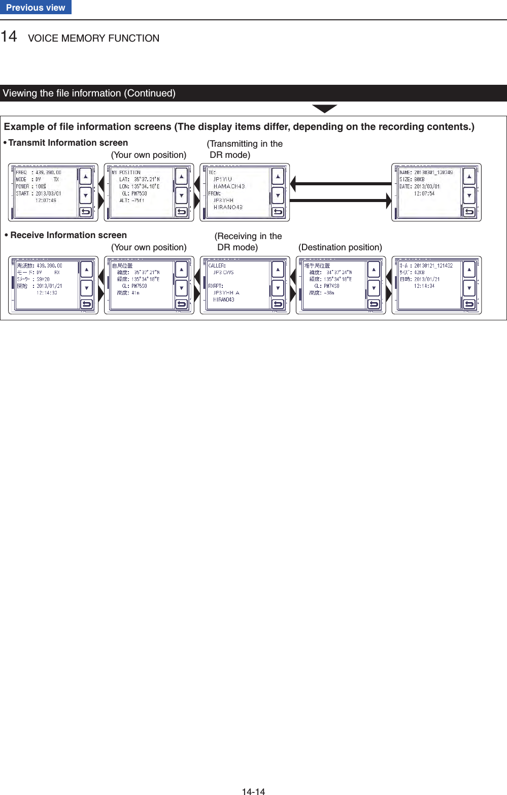
![14 VOICE MEMORY FUNCTION14-15Previous viewPush qSET(C) to enter the Set mode. Touch the “SD Card” item. w • If the specifi ed item is not displayed, touch [∫] or [√](D) one or more times to select the page. Touch the “SD Card Info” item. e • The information screen appears. Touch [ r](C) to cancel the information screen. • Touching SET(C) or QUICK(C) also cancels. Push tSET(C) to exit the Set mode.Viewing the SD card’s free space and recordable timeSETShows the information screen.The L, R, C or D in the instructions indicate the part of the controller.L: Left sideR: Right sideC: Center bottomD: Display (Touch panel)Left RightCenterDisplayTouch“SD Card.”Touch“SD Card Info.”](https://usermanual.wiki/ICOM-orporated/339300/User-Guide-2000118-Page-150.png)
![14 VOICE MEMORY FUNCTION14-16Previous viewYou can also playback the voice memory data on a PC.However, the recorded information (frequency, date, and so on) are not displayed.• Mircosoft® Windows® 7 is used for the description.Example: Connect a memory card reader (3rd party product) to the PC, and insert the SD card into the reader. Then playing back the voice memory data in the card. • When you copy the voice memory data from the SD card to the PC’s hard disk drive, you also operate the same as following steps for playing back data. Connect the memory card reader to the PC, and qthen insert the SD card into the reader. • If your PC has an SD card drive, insert the card into the drive. When the SD card is inserted in the SD card drive of wthe PC or the SD card reader, the screen appears, as shown to the right. • The [IC-7100] folder appears. Double-click the [IC-7100] folder. eDouble-clickDouble-clickNOTE: • The operations while playing back may differ, de-pending on the software. Therefore, refer to the software’s instruction manual for details.• When the fi le does not playback, even if you dou-ble-click the fi le, download appropriate software like Windows Media® Player. Double-click the [Voice] folder. r Double-click the folder in which the fi le you want to tplayback is stored. (Example: 20130301 folder) To playback the fi le, double-click it. y (Example: 20130301_184451.wav)ClickDouble-clickDouble-clickPlaying back the voice memory data on a PCSD cardTransceiverTo the Card readerPC](https://usermanual.wiki/ICOM-orporated/339300/User-Guide-2000118-Page-151.png)
 to select the Voice TX mode. • The “VOICE TX” screen is displayed. Push eMENU (C) to display the “VOICE” screen. Touch [REC]( rD) to display the “VOICE TX RECORD” screen. Touch the desired memory, [T1] through [T4]. t • The “VOICE TX RECORD (T1)” screen is displayed, when [T1] memory is selected.Touch [ y●](D) to start recording. • Touch [■](D) to cancel recording. • The maximum record time is 90 seconds. • Hold the microphone 5 to 10 cm (2 to 4 inches) from your mouth, then speak at a normal voice level. • Touch [MIC GAIN](D) to display the “MIC GAIN” screen. • If you record again on the same channel, the current con-tents will be overwritten. Touch [ u](C) to return to the “VOICE TX RECORD” screen.Information ✓To delete the recorded au-dio, touch the center of the “VOICE TX RECORD (T1)” through “VOICE TX RECORD (T4)” screen for 1 second, or push QUICK(C), and then touch “Clear.”Recording the voice audioTouch [VOICE]Touch [REC](Example)Touch [T1]Push MENUTouch [●]The “MIC GAIN” screen appears after touchingShows the audio input level.While recordingAdjust so the REC level bar does not reach this level.The L, R, C or D in the instructions indicate the part of the controller.L: Left sideR: Right sideC: Center bottomD: Display (Touch panel)Left RightCenterDisplay](https://usermanual.wiki/ICOM-orporated/339300/User-Guide-2000118-Page-153.png)
 to select the Voice TX mode. • The “VOICE TX” screen is displayed. Push eMENU (C) to display the “VOICE” screen. Touch [REC]( rD) to display the “VOICE TX RECORD” screen. Touch the desired memory, [T1] through [T4]. t • The “VOICE TX RECORD (T1)” screen is displayed, when [T1] memory is selected. Touch [ y≈](D) to start the playback. • Touch [■](D) to stop the playback. Touch [ u](C) to return to the “VOICE TX RECORD” screen.Touch [VOICE]Touch [REC](Example)Touch [T1]Push MENUTouch [≈]While playingThe L, R, C or D in the instructions indicate the part of the controller.L: Left sideR: Right sideC: Center bottomD: Display (Touch panel)Left RightCenterDisplay](https://usermanual.wiki/ICOM-orporated/339300/User-Guide-2000118-Page-154.png)
![15 VOICE TX FUNCTION15-4Previous viewEach Voice TX memory, [T1] through [T4], can be pro-grammed with an alphanumeric name of up to 16 char-acters.[EXAMPLE]: Programming the memory name “Con-test” in [T1]. Push qMENU (C) one or more times to select the “M-2” (Menu 2) screen. • In the DR mode, select the “D1” screen. Touch [VOICE]( wD) to select the Voice TX mode. • “VOICE TX” screen is displayed. Push eMENU (C) to display the “VOICE” screen. Touch [REC]( rD) to display the “VOICE TX RECORD” screen. Touch the desired memory, [T1] through [T4], tfor 1 second to program. Touch [Edit Name] to display the “VOICE TX RE- yCORD (T1)” screen (Voice TX name edit screen). • A cursor appears and blinks. Touch the desired block one or more times to uselect the desired character or symbol.Selectable characters and symbolsA to Z, a to z, 0 to 9, ! # $ % & \ ? " ’ ` ^ + – ✱ ⁄ . , : ; = < > ( ) [ ] { } ¦ _ ¯ @ (space) • Touch “AB12” to toggle between the Alphabet input and Number input mode. • Touch [CLR](D) to delete the selected character, symbol or number. • Touch [SYMB](D) to open the Symbol character selec-tion window. • Touch “” to input a space.Programming a memory nameTouch [Edit Name].Touch [REC](Example)Touch [T1] for 1 second.Continued on the next page. ☞The L, R, C or D in the instructions indicate the part of the controller.L: Left sideR: Right sideC: Center bottomD: Display (Touch panel)Left RightCenterDisplayInput a spaceMove the cursorDelete a characterSelect an input modeEnterCancel editMove the cursorInput mode screenTouch [!"#] to open the Symbol character selec-tion window.Memory name edit screen](https://usermanual.wiki/ICOM-orporated/339300/User-Guide-2000118-Page-155.png)
![15 VOICE TX FUNCTION15-5Previous viewProgramming a memory name (Continued)After programming, touch [ENT]Touch [] to can-cel the “VOICE TX RECORD” screen Touch [ i](D) to move the cursor backwards, or touch [](D) to move the cursor forwards. Repeat steps ou and i to program up to 16 char-acters memory name, and then touch [ENT](D) to save the name, and return to the “VOICE TX RE-CORD” screen.!0 Touch [](D) to return to the “VOICE TX RECORD” screen.](https://usermanual.wiki/ICOM-orporated/339300/User-Guide-2000118-Page-156.png)
 to select the Voice TX mode. • “VOICE TX” screen is displayed. Push eMENU (C) to display the “VOICE” screen. r<<Single TX>> Touch the desired memory, [T1] through [T4] to transmit the recorded voice audio once. <<Repeat TX>> Touch the desired memory, [T1] through [T4] for 1 second to repeatedly transmit the recorded voice audio for up to 10 minutes at the interval specified in “Repeat Time.” • Even if 10 minutes pass while transmitting, the voice au-dio is completely transmitted. • During the Voice TX waiting, the selected memory blinks. • One of the following steps will cancel the transmission. - Touch the memory again. - Turn OFF the power, then turn it ON again. - Touch another memory (except for [LEVEL]). - Push MENU(C), XFC(R) or SET(C). - Push QUICK(C). The repeat transmission is cancelled. But while trans-mitting, the voice audio is completely transmitted. • Once the Repeat TX is made, the transceiver pauses until the end of the “Repeat Time,” then transmits again. After the second transmission, the Repeat TX continues pausing, if receiving a signal. But if the squelch is manually opened, the voice audio is repeatedly transmitted, according to the repeat time set-ting.• Voice TX Waiting screen for <<Repeat TX>>Transmitting the recorded voice audioBlinks while transmittingTouch [VOICE]Touch the desired memory,Single TXRepeat TXBlinksThe L, R, C or D in the instructions indicate the part of the controller.L: Left sideR: Right sideC: Center bottomD: Display (Touch panel)Left RightCenterDisplay](https://usermanual.wiki/ICOM-orporated/339300/User-Guide-2000118-Page-157.png)
 to select the Voice TX mode. • “VOICE TX” screen is displayed. Touch [LEVEL]( eD) to display the “TX LEVEL” screen.Rotate the Dial to adjust the transmit voice level. r • Too high of a voice level may cause interference. • Touch [DEF](D) for 1 second to reset to the default set-ting (50 %), if desired. Touch [LEVEL]( tD) to save, and exit the “TX LEVEL” screen.Transmitting the recorded voice audio (Continued)Touch [VOICE]Touch[LEVEL]Rotate the Dial to adjustExits the “TX LEVEL” screen.Reset to the default settingHiding the Voice TX memory nameThe voice TX memory name can be hidden on the “VOICE TX” screen.Push qSET(C) to enter the Set mode. Touch the “VOICE TX Name Display” item of the w“Display” Set mode. ( Display > VOICE TX Name Display) • If the specifi ed item is not displayed, touch [∫] or [√](D) one or more times to select the page. Touch “OFF.” e Push rSET(C) to exit the Menu screen.The voice TX memory name is displayed.The voice TX memory name is not displayed.When “ON” is selected. When “OFF” is selected.Setting the VOICE fi rst menu screenSelect the first appearance screen after touching [VOICE](D).Push qSET(C) to enter the Set mode. Touch the “VOICE 1st menu” item of the “Function” wSet mode. ( Function > VOICE 1st menu) • If the specifi ed item is not displayed, touch [∫] or [√](D) one or more times to select the page. Touch the desired option. e • VOICE-Root: Displays the “VOICE” screen fi rst. • VOICE-TX: Displays the “VOICE TX” screen fi rst. Push rSET(C) to exit the Menu screen.“M-2” (Menu 2) screenDisplays the “VOICE” screen fi rst.Displays the “VOICE TX” screen fi rst.After touching [VOICE].When “VOICE-Root” is selected.When “VOICE-TX” is selected.](https://usermanual.wiki/ICOM-orporated/339300/User-Guide-2000118-Page-158.png)
![15 VOICE TX FUNCTION15-8Previous viewRepeat Time (Default: 5sec)Set the repeat interval to between 1 and 15 seconds (in 1 second steps) for the voice repeat transmission.The transceiver repeatedly transmits the recorded voice audio at this interval.Auto Monitor (Default: ON)Turn the TX Monitor function ON or OFF.• OFF: The TX voice audio is not heard from the speak-er.• ON: The TX voice audio is heard from the speaker.Touch [VOICE]Touch [SET]Touch a de-sired item.( Example: Re-peat Time)Touch a de-sired option.( Example: 7sec)Push MENUVoice TX Set mode Push qMENU (C) one or more times to select the “M-2” (Menu 2) screen. • In the DR mode, select the “D1” screen. Touch [VOICE]( wD) to select the Voice TX mode. • “VOICE TX” screen is displayed. Push eMENU (C) to display the “VOICE” screen. Touch [SET]( rD) to display the “VOICE TX SET” screen. Touch a desired item. t Touch a desired option. y • See the descriptions below for details of items and op-tions. • Push QUICK (C), and then touch “Default” to reset to the default setting, if desired. Push uMENU (C) to return to the “VOICE” screen.](https://usermanual.wiki/ICOM-orporated/339300/User-Guide-2000118-Page-159.png)
![16 ANTENNA TUNER OPERATION16-2Previous viewConnecting the antenna tunerTo Long wireTo optional AH-2bGroundAH-4To [ANT]IC-7200To [TUNER]Ground*ANTAntennaelementTo [TRANSCEIVER]To [ANT]To [ACC]AT-180To [ANT] To [ACC]*GroundHF/6 m antennaCoaxial cable suppliedwith the AT-180ACC cable supplied with the AT-180Coaxial cableGroundIC-7100 *Either of the two external connectors* Use as thick and short a wire as possible between the AH-4 and ground.Connecting an AH-4 DThe optional AH-4 matches the IC-7100 to a long wire antenna more than 7 m/23 ft long (3.5 MHz and above).• See page ??-?? for operation.• See the AH-4 instruction manual installation and an-tenna connection details.The AH-4 and AT-180 AUTOMATIC ANTENNA TUNER matches the IC-7100 to the connected antenna auto-matically.Once the tuner matches an antenna, the variable ca-pacitor settings are memorized as a preset point for each frequency range (100 kHz steps). Therefore, when you change the frequency range, the variable capaci-tors are automatically preset to the memorized point.NOTE: Before connecting, be sure to turn OFF the transceiver’s power.Connecting an AT-180 DThe optional AT-180 matches the IC-7100 to both HF and 50 MHz antenna, and automatically tunes the an-tenna (impedance range: 16.7 to 150 ø) during trans-mission when the antenna SWR is less than 1.5:1.• See page ??-?? for operation.](https://usermanual.wiki/ICOM-orporated/339300/User-Guide-2000118-Page-161.png)
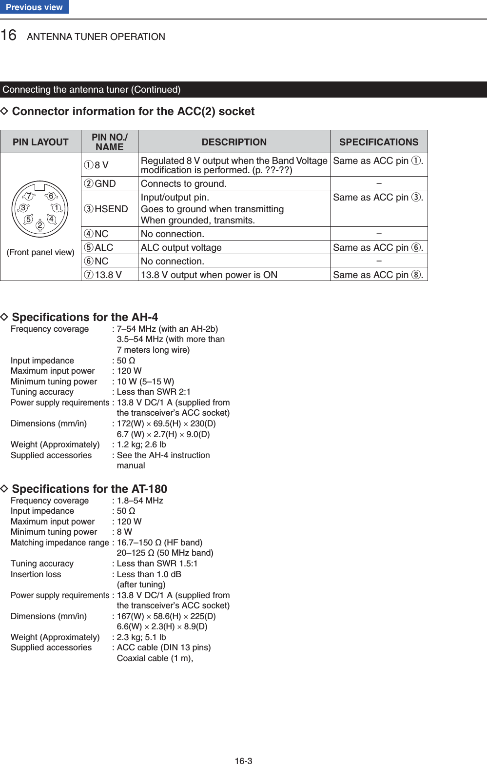
![16 ANTENNA TUNER OPERATION16-4Previous viewOperating the AH-4Before operating DR DANGER HIGH VOLTAGE!NEVER touch the antenna element while tuning or transmitting.Always place it in a secure place.NEVER operate the AH-4 without an antenna connect-ed. The tuner and transceiver will be damaged.NEVER operate the AH-4 when it is ungrounded.Transmitting before tuning may damage the transceiver. Note that the AH-4 cannot tune when using a 1⁄2O long wire or on a multiple of that frequency.Operating DTuning is required for each frequency. Be sure to retune the antenna before transmitting when you change the frequency—even slightly. Push qTUNER/CALL(L) or [TUNER/CALL] on the re-mote control microphone to turn ON the AH-4. The CW mode and 10 W output power are automati-cally selected, and the tuning starts. • The TX indicator lights red. • “ ” blinks while tuning. • After changing the frequency, you should hold down TUNER/CALL(L) or [TUNER/CALL] on the remote control microphone for second to manually start tuning. In this case, the CW mode and 10 W output power are auto-matically selected, and the TX indicator lights red. NOTE: DO NOT change the frequency and oper-ating mode while “ ” is blinking. It may takes approximately 2 to 3 seconds (maximum of 15 seconds) to complete tuning. w“ ” is still ON after the tuning is completed, and the previously selected operating mode and the out-put power are automatically selected. • When the connected wire cannot be tuned, “ ” goes out, the AH-4 is bypassed and the antenna wire is di-rectly connected.PTT tune function DThe AH-4 always tunes when [PTT] is pushed after the frequency is changed on an HF band (more than 1%). Turn ON this function in the Set mode.(Function > Tuner > PTT Start)The L, R, C or D in the instructions indicate the part of the controller.L: Left sideR: Right sideC: Center bottomD: Display (Touch panel)Left RightCenterDisplayTUNER/CALL[TUNER/CALL]](https://usermanual.wiki/ICOM-orporated/339300/User-Guide-2000118-Page-163.png)
![16 ANTENNA TUNER OPERATION16-6Previous viewOperating DThe AT-180 AUTOMATIC ANTENNA TUNER automatically matches to your antenna. Once the tuner matches the antenna, the variable capacitor settings are memorized as a preset point for each frequency range (100 kHz steps). Therefore, when you change the frequency range, the variable capacitors are automatically preset to the memorized point.NOTE:• The AT-180 can match both the HF and 50 MHz bands. However, operation is different for the bands.• When connecting the AT-180, the transceiver’s out-put power should be more than 8 W. Otherwise, the AT-180 may not tune correctly. The AT-180’s mini-mum operating input power is 8 W. Check the transceiver’s output power is set to 8 W/ q Push wTUNER/CALL(L) or [TUNER/CALL] on the re-mote control microphone to turn ON the AT-180. • “ ” appears. For the HF band: The antenna is automatically tuned during transmit if the antenna SWR is higher than 1.5:1. For the 50 MHz band: “” blinks if the antenna SWR is higher than 1.5:1, regardless of the internal switch position de-scribed on the page ??-??. In this case, do the step e to manually tune the antenna. • If you continue to transmit without retuning, “ ” goes out after approximately 10 seconds, the AH-4 is bypassed and the antenna wire is directly connected. Push eTUNER/CALL(L) or [TUNER/CALL] on the re-mote control microphone for 1 second to start man-ual tuning. • When the CW mode is selected, a side tone is emitted, and “ ” blinks. NOTE: DO NOT change the frequency and oper-ating mode while “ ” is blinking. r“ ” is still ON after the tuning is completed, and the previously selected operating mode is automati-cally selected. • When the connected wire cannot be tuned, “ ” goes out, the AH-4 is bypassed and the antenna wire is di-rectly connected.Once the tuner matches the antenna, the variable capacitors are automatically preset to the memo-rized point when you change the frequency range in 100 kHz steps.• While presetting, “ ” blinks.Operating the AT-180 (Continued)TUNER/CALL[TUNER/CALL]The L, R, C or D in the instructions indicate the part of the controller.L: Left sideR: Right sideC: Center bottomD: Display (Touch panel)Left RightCenterDisplay](https://usermanual.wiki/ICOM-orporated/339300/User-Guide-2000118-Page-165.png)
![16 ANTENNA TUNER OPERATION16-7Previous viewSetting the AT-180 internal switchesThe optional AT-180 has 3 operating confi gurations for HF band operation. Select a suitable confi gurations for your antenna system.q Remove the top cover of the AT-180.w Set the tuner switches to the desired positions ac-cording to the table below.Automatic tuner start D(HF bands only)If you want to turn OFF the tuner when the VSWR is 1.5:1 or less, use “automatic tuner on” and turn OFF the tuner. See page 10-11 for automatic tuner function.PTT tune function DThe AT-180 tunes when [PTT] is pushed after the frequency is changed (more than 1%) if the AT-180 is turned ON. This function removes the “hold down TUNER ” operation and activates with the fi rst transmis-sion on the new frequency. (p. 10-11)Turn this function ON in the Set mode.SW Position OperationS1A(default)The tuner operating mode is set by S2 described below.BTHROUGH INHIBITThe tuner tunes the antenna even when the antenna has poor SWR (up to VSWR 3:1 after tuning). In this case, manual tun-ing is necessary each time you change the frequency although the tuner auto-matically starts tuning when the VSWR is higher than 3:1. This setting is called “through inhibit,” however, the tuner is set to “through” if the VSWR is higher than 3:1 after tuning.S2CTUNER SENSITIVE SETTINGThe tuner tunes each time you transmit (except SSB mode). Therefore, the low-est SWR is obtained at any given time.For SSB mode, the same SETTING as the “D” position.D(default)NORMALThe tuner tunes when the SWR is higher than 1.5:1. Therefore, the tuner activates only when tuning is necessary.• AT-180 inside top coverS2 S1DC BA](https://usermanual.wiki/ICOM-orporated/339300/User-Guide-2000118-Page-166.png)
![17 SET MODE17-2Previous viewThe Set mode is used to program infrequently changed values or function settings.NOTE: The Set mode is constructed in a tree struc-ture. You may go to the next tree level, or go back a level, depending on the selected item.SETwerutyThe Set mode settings DPush qSET(C) to enter the Set mode. If the specifi ed item is not displayed, touch [ w∫] or [√](D) one or more times to select the page. • If [∫](D) or [√](D) is continuously held down, the pages are quickly scrolled. • Rotating the Dial also selects the pages. Touch the desired item to go to the next level. e Repeat steps rw and e to show the desired item’s setting screen. • To go back the previous tree level, touch [](D), or MENU (C). Touch a desired option shown on the display, or [+]/ t[–](D) to adjust a level. • When you touch an option, it is automatically saved and the screen returns to the previous display. • Rotating the Dial also adjusts the level. • Push QUICK (C), and then touch “Default” to reset to the default setting, if desired. • To set other item, touch [](D), or MENU (C) to go back a tree level. Push ySET(C) to exit the Set mode.Set mode descriptionThe L, R, C or D in the instructions indicate the part of the controller.L: Left sideR: Right sideC: Center bottomD: Display (Touch panel)Left RightCenterDisplay](https://usermanual.wiki/ICOM-orporated/339300/User-Guide-2000118-Page-168.png)
![17 SET MODE17-3Previous viewNOTE: The default settings shown below in bold are for the USA version.The default settings may differ, depending on your transceiver version.Call sign (Section 9) ➥RX Record (Section 9) ➥MY Station (Section 7) ➥SD Card (Section 13) ➥GPS (Section 10) ➥Voice Memo In this item, set the TX/RX voice recording options.QSO Recorder<<REC Start>>* Starts recording the received audio.Play Files*Selects to playback or delete the recorded audio.Recorder SetREC Mode TX&RX or RX Only Selects to record the TX audio or not.RX REC Condition Always or Squelch Auto Selects whether or not the squelch status affects the RX voice audio recording.File Split OFF or ON Selects whether or not to automatically create a new fi le after each transmission, reception, or each time the squelch opens or closes.PTT Auto REC OFF or ON Turns the PTT Automatic Recording function ON or OFF.Player SetSkip Time 3sec, 5sec, 10sec or 30sec Sets the Skip time to rewind or forward the re-corded audio when you push the fast-rewind or fast-forward key during playback.DV Auto Reply* Records a voice audio to use for the Auto Reply function in the DV mode.* Be sure to insert the SD card into the transceiver before selecting these items.DV Set In this item, set infrequently changed values or functions in the DV mode.Standby Beep OFF, ON or ON (to me: High Tone) Selects whether or not to sound a beep after a received signal disappears.Auto Reply OFF, ON or Voice Selects whether or not to automatically reply to a call addressed to your own call sign.DV Data TX PTT or Auto Selects to manually or automatically transmit low speed data.Digital Monitor Auto, Digital or Analog Selects the DV mode RX monitoring when [XFC] is held down.Digital Repeater Set OFF or ON Turns the digital repeater setting function ON or OFF. This function is usable in any DV mode ex-cept the DR mode.RX Call Sign Write OFF or Auto Turns the RX call sign automatic write function ON or OFF. This function is usable in any DV mode except the DR mode.RX Repeater Write OFF or Auto Turns the repeater call sign automatic write func-tion ON or OFF. This function is usable in any DV mode except the DR mode.DV Auto Detect OFF or ON Turns the DV mode automatic detect function ON or OFF.RX Record (RPT) ALL or Latest Only Selects whether to record all calls or only the lat-est call, when the received signal includes a sta-tus message (“UR?” or “RPT?”) that is sent back from the access repeater.BK OFF or ON Turns the BK (Break-in) function ON or OFF.The BK function allows you to break into a con-versation between two stations with call sign squelch enabled.EMR OFF or ON Turns the EMR (Enhanced Monitor Request) communication mode ON or OFF.After turning OFF the transceiver, the EMR mode will be cancelled.EMR AF Level 0%~50%~100% Sets the audio output level when an EMR mode signal is received.Set mode items and Default settings](https://usermanual.wiki/ICOM-orporated/339300/User-Guide-2000118-Page-169.png)
![17 SET MODE17-4Previous viewSPEECH In this item, set the Speech options.RX Call Sign SPEECH OFF, ON (Kerchunk) or ON (All) Selects the RX call sign speech function option while ON, or turn it OFF.RX>CS SPEECH OFF or ON Turns the RX>CS Speech function ON or OFF.S-Level SPEECH OFF or ON Turns the Signal Strength Level Speech function ON or OFF.MODE SPEECH OFF or ON Turns the Operating Mode Speech function ON or OFF.SPEECH Language English or Japanese Selects either English or Japanese as the de-sired speech language.Alphabet Normal or Phonetic Code Selects the alphabet character announcement type.SPEECH Speed Slow or Fast Selects Slow or Fast speech speed.SPEECH Level 0%~50%~100% Sets the volume level for the voice synthesizer.QSO/RX Log In this item, set the QSO/RX History Log options.QSO Log*1OFF or ON Selects whether or not to make a communication log on the SD card.RX History Log*1OFF or ON Selects whether or not to make a DV mode’s re-ceive history log on the SD card.CSV FormatSeparator/Decimal Sep [,] Dec [.]*2, Sep [;] Dec [.] or Sep [;] Dec [,]Selects the separator and the decimal character for the CSV format.Date yyyy/mm/dd, mm/dd/yyyy*2 or dd/mm/yyyySelects the date format.*1 Be sure to insert the SD card into the transceiver before selecting these items.*2 The default value may differ, depending on the transceiver version.Set mode items and Default settings (Continued)NOTE: The default settings shown below in bold are for the USA version.The default settings may differ, depending on your transceiver version.](https://usermanual.wiki/ICOM-orporated/339300/User-Guide-2000118-Page-170.png)
![17 SET MODE17-5Previous viewFunction In this item, set the function options.Monitor OFF or ON Selects whether or not to monitor your transmit signal in any mode other than CW.Monitor Level 0%~50%~100% Sets the monitor level.Beep Level 0%~50%~100% Sets the beep output level.Beep Level Limit OFF or ON Selects whether or not to limit the volume to the specifi ed level, and further rotation of the [AF] control will not increase the level.Beep (Confi rmation) OFF or ON Turns the confi rmation beep tones ON or OFF.Band Edge Beep OFF, ON (Default), ON (User) or ON (User) & TX LimitSelects whether or not to sound a beep when you tune outside of, or back into the amateur band's frequency range.User Band Edge 1: 1.800.000–1.999.9992: 3.500.000–3.999.9993: 7.000.000–7.300.0004: 10.100.000–10.150.0005: 14.000.000–14.350.0006: 18.068.000–18.168.0007: 21.000.000–21.450.0008: 24.890.000–24.990.0009: 28.000.000–29.700.00010: 50.000.000–54.000.00011: 144.000.000–146.000.00012: 430.000.000–440.000.00013~30: (blank)Selects the user band frequency range to sound a beep when the Band Edge Beep function is set to “ON (User)” or “ON (User) & TX Limit,” and you tune outside of, or back into a programmed range.RF/SQL Control Auto, SQL or RF+SQL Select the function of the [RF/SQL] control.TX DelayHF OFF, 10ms, 15ms, 20ms, 25ms or 30msSets the transmission’s timing of the IC-7100 to prevent any external equipment that is connected from damage by the refl ected wave.50M OFF, 10ms, 15ms, 20ms, 25ms or 30msSets the transmission’s timing of the IC-7100 to prevent any external equipment that is connected from damage by the refl ected wave.144M OFF, 10ms, 15ms, 20ms, 25ms or 30msSets the transmission’s timing of the IC-7100 to prevent any external equipment that is connected from damage by the refl ected wave.430M OFF, 10ms, 15ms, 20ms, 25ms or 30msSets the transmission’s timing of the IC-7100 to prevent any external equipment that is connected from damage by the refl ected wave.Time-Out Timer OFF, 3min, 5min, 10min, 20min or 30minSelects the Time-Out Timer time options to pre-vent an accidental prolonged transmission.PTT Lock OFF or ON Selects whether or not to inhibit transmission.SPLIT/DUPQuick SPLIT OFF or ON Turns the Quick SPLIT function ON or OFF.SPLIT Offset –9.999 MHz~0.000 MHz~+9.999 MHz Sets the frequency offset for the Split function.SPLIT LOCK OFF or ON Turns the SPLIT LOCK function ON or OFF.DUP Offset0.0000 MHz~9.9999 MHz( The default value may differ, depend-ing on the frequency band and the transceiver version.)Sets the frequency offset for repeater operation.One Touch Repeater DUP– or DUP+ Selects the duplex direction for the One Touch Repeater function.Auto Repeater OFF, ON (DUP) or ON (DUP,TONE) Turns the Auto Repeater function ON or OFF.Set mode items and Default settings (Continued)NOTE: The default settings shown below in bold are for the USA version.The default settings may differ, depending on your transceiver version.](https://usermanual.wiki/ICOM-orporated/339300/User-Guide-2000118-Page-171.png)
![17 SET MODE17-6Previous viewTunerAuto Start OFF or ON Turns the automatic antenna tuner function ON or OFF.PTT Start OFF or ON Turns the PTT Tuner Start function ON or OFF.[TUNER] Switch Manual or Auto Selects whether or not to store the AT-180’s sta-tus by each band.[SPEECH/LOCK] Switch SPEECH/LOCK, LOCK/SPEECH Selects the function for SPEECH when pushed or held down.Lock Function MAIN DIAL or PANEL Selects the dial lock function to prevent frequen-cy changes by accidental movement of the tun-ing dial.Memopad Numbers 5 or 10 Sets the number of usable memopad channels.MAIN DIAL Auto TS OFF, LOW or HIGH Selects an option for the automatic tuning step function. When rapidly rotating the main dial, the tuning step automatically changes according to the setting.MIC Up/Down Speed Slow or Fast Selects the steps per second when changing an operating frequency by holding down the micro-phone’s [∫]/[√] key.[NOTCH] Switch (SSB) Auto, Manual or Auto/Manual Selects the notch function for the SSB mode.[NOTCH] Switch (AM) Auto, Manual or Auto/Manual Selects the notch function for the AM mode.SSB/CW Sync Tuning OFF or ON Turns the Synchronous Tuning function ON or OFF to shift the operating frequency by the offset amount to keep receiving a signal when the oper-ating mode is changed between SSB and CW.CW Normal Side LSB or USB Sets the carrier point for CW normal mode op-eration to the LSB side or the USB side.VOICE 1st Menu VOICE-Root or VOICE-TX Select whether or not to directly select the voice send menu, skipping the voice menu.KEYER 1st Menu KEYER-Root or KEYER-SEND Select whether or not to directly select the keyer send menu, skipping the memory keyer menu.Speaker Out OFF or ON Selects to mute the speaker output.MIC AF Out OFF or ON Selects to output the received audio from the [MIC] connector.RC MIC[F-1] ---, P.AMP/ATT, AGC, NB, NR, NOTCH, RIT, AUTOTUNE/RX>CS, TS, MPAD, M-CLR, BANK, SPLIT, A/B, DUP, TONE/DSQL, COMP, TBW, METER, DR, FROM/TO(DR), SCAN, Voice TX (T1)The functions listed to the left can be set to [F-1] of the optional HM-151 REMOTE CONTROL MIC.[F-2] ---, P.AMP/ATT, AGC, NB, NR, NOTCH, RIT, AUTOTUNE/RX>CS, TS, MPAD, M-CLR, BANK, SPLIT, A/B, DUP, TONE/DSQL, COMP, TBW, METER, DR, FROM/TO(DR), SCAN, Voice TX (T1)The functions listed to the left can be set to [F-2] of the optional HM-151 REMOTE CONTROL MIC.Mode Select SSB, CW, RTTY, AM, FM, WFM, DV(All boxes are checked.)Disables the mode selection of the optional HM-151 REMOTE CONTROL MIC, to simplify operation.Power OFF (With No Controller) OFF or ON Selects whether or not to automatically turn OFF the transceiver when the controller is disconnect-ed from the transceiver.REF Adjust 0 %~100 % Sets a number to adjust for a zero beat with a standard signal such as WWV or WWVH, for fre-quency calibration.Set mode items and Default settings (Continued)NOTE: The default settings shown below in bold are for the USA version.The default settings may differ, depending on your transceiver version.](https://usermanual.wiki/ICOM-orporated/339300/User-Guide-2000118-Page-172.png)
![17 SET MODE17-8Previous viewConnectors In this item, set the external connector’s options.USB Audio SQL OFF (OPEN) or ON Selects whether or not to output the audio from the [USB] connector, according to the squelch state (open or closed).ACC/USB Output Select AF or IF Sets the [USB] connector and the [ACC] socket usage to received audio output or the IF output for DRM (Digital Radio Mondiale).ACC/USB AF Level 0 %~50 %~100 % Sets the audio output level at the [ACC] socket and the [USB] connector.ACC/USB IF Level 0 %~50 %~100 % Sets the IF output level at the [ACC] socket and the [USB] connector.ACC MOD Level 0 %~50 %~100 % Sets the input modulation level at the [ACC] socket.DATA MOD Level 0 %~50 %~100 % Sets the input modulation level at the [DATA] jack.USB MOD Level 0 %~50 %~100 % Sets the input modulation level at the [USB] con-nector.DATA OFF MOD MIC, ACC, MIC,ACC or USB Selects the connector(s) for the desired modula-tion to input when the data mode is not used.DATA MOD MIC, ACC, MIC,ACC or USB Selects the connector(s) for the desired modula-tion to input when the data mode is used.External KeypadVOICE OFF or ON Selects whether or not to transmit voice memory contents using the external keypad.KEYER OFF or ON Selects whether or not to transmit keyer memory contents using the external keypad.RTTY OFF or ON Selects whether or not to transmit RTTY memory contents using the external keypad. CI-VCI-V Baud Rate 300, 1200, 4800, 9600, 19200 or Auto Sets the CI-V code transfer speed.CI-V Address 01h~88h~DFh Sets the transceiver's unique CI-V hexadecimal address code.CI-V Transceive OFF or ON Turns the CI-V Transceive function ON or OFF.USB2/DATA1 FunctionUSB2 Function OFF, RTTY Decode or DV Data Selects the use of the COM port (USB2).DATA1 Function OFF, RTTY Decode, DV Data or GPS Select the use of the [DATA1] jack.GPS Out OFF or DATA1 USB2 Selects whether or not to output the data to the COM port (USB2) when data is input from a GPS receiver through the [DATA1] jack.DV Data/GPS Out Baud 4800 or 9600 Sets the DV or GPS data transfer speedRTTY Decode Baud 300, 1200, 4800, 9600 or 19200 Sets the RTTY decode monitor speed.VSEND Select OFF, UHF or VHF/UHF Selects the band to use for the [ACC] socket’s pin 7 (VSEND usage).9600bps Mode OFF or ON Selects whether or not to allow data transmission at 9600 bps.Set mode items and Default settings (Continued)NOTE: The default settings shown below in bold are for the USA version.The default settings may differ, depending on your transceiver version.](https://usermanual.wiki/ICOM-orporated/339300/User-Guide-2000118-Page-174.png)
![17 SET MODE17-11Previous view<<REC Start>>Voice Memo > QSO Recorder > <<REC Start>>Insert an SD card into the transceiver before select-ing this item.Touch [<<REC Start>>] to start voice recording.• “Recording started.” appears.• [<<REC Stop>>] is displayed while recording.Once recording has started, the recording will con-tinue, even the transceiver is rebooted.To stop the recording, touch [<<REC Stop>>].Play FilesVoice Memo > QSO Recorder > Play Files (PLAY FILES)Insert an SD card into the transceiver before select-ing this item.Do the following steps to play back the recorded audio on the SD card.Touch [Play Files], and folders on the SD card are dis-played.• These folders contain the stored fi les.Playing back Touch [ q∫] or [√], or rotate [DIAL] to select the folder that includes the desired fi le to play back, and then touch the folder. Touch [ w∫] or [√], or rotate [DIAL] to select the fi le to play back, and then touch the fi le.• The VOICE PLAYER screen is displayed and the select-ed fi le is played back.• See “Operation while playing back” for forwording or re-winding. (p. ??-??) Push eMENU or touch [] on the display to stop the playback.• Returns to the fi le list screen.NOTE:• The folder name is automatically created, as shown in the example below: (Example) Recording date: 2013/3/1 Folder name: 20130301• The fi le name is automatically created, as shown in the example below: (Example) Recording date: 2013/3/1 15:30:00 File name: 20130301_153000• The voice audio is recorded onto an SD card, and saved in the “wav” format.The recorded voice audio can also be played back on a PC.The extension, “wav,” is not displayed on the trans-ceiver’s screen.REC Mode (Default: TX&RX)Voice Memo > QSO Recorder > Recorder Set > REC Mode (REC Mode)Records both the transmitted and received audio as the default setting.• TX&RX: Records both the transmitted and received audio.• RX Only: Records only the received audio.When transmitting while recordingWhen “OFF” is selected in File Split, the recording is paused. After you stop transmitting, the recording re-sumes.When “ON” is selected in File Split, a new fi le is auto-matically created, and the transmitted audio is recorded into the new one.RX REC Condition (Default: Squelch Auto)Voice Memo > QSO Recorder > Recorder Set > RX REC Condition (RX REC Condition)Select whether or not the squelch status affects the RX voice audio recording.• Always: The transceiver always records the RX audio regardless of the squelch sta-tus.• Squelch Auto: The transceiver records the RX audio only when a signal is received (the squelch is opened). When the squelch closes while record-ing, the recording will continue for 2 seconds, and then pause.When “ON” is selected in File Split, and if the squelch either opens or closes while recording, a new fi le is automatically created.Voice Memo Set mode](https://usermanual.wiki/ICOM-orporated/339300/User-Guide-2000118-Page-177.png)
![17 SET MODE17-13Previous viewStandby Beep (Default: ON)DV Set > Standby Beep (Standby Beep)Turn the standby beep function ON or OFF.This function sounds a beep after a received signal dis-appears.• OFF: Turns the function OFF.• ON: Turns the function ON to sound a beep.• ON (to me: High Tone): Turns the function ON to sound a beep. If the signal is addressed to your call sign, a high pitch beep sounds.NOTE:• Even if “Beep (Confirmation)” of the Function screen is OFF, the standby beep sounds. • The standby beep output level can be set in “Beep Level” of the Function screen.Auto Reply (Default: OFF)DV Set > Auto Reply (Auto Reply)Set the automatic reply function to ON, OFF or Voice.This function automatically replies to a call addressed to your own call sign, even if you are away from the transceiver.When “ON” or “Voice” is selected, the automatic reply function is automatically turned OFF when you push [PTT].• OFF: The automatic reply function is OFF.• ON: Replies with your own call sign. (No audio reply is sent)• Voice: Replies with your call sign and any Auto Reply message recorded on the microSD (up to 10 seconds). If no SD card is inserted or no message is re-corded, only your call sign is transmitted. The transmitted audio will be heard from the speak-er.DV Data TX (Default: Auto)DV Set > DV Data TX (DV Data TX)Select whether to manually or automatically transmit slow-speed data.• PTT: Push [PTT] to manually transmit the input data. • Auto: When data is input from a PC through either the [USB2] port or [DATA1] jack*, the transceiver automatically transmits it. * “USB2 Function” or “USB2 Function” item must be set to “DV Data.” (p. ??)Digital Monitor (Default: Auto)DV Set > Digital Monitor (Digital Monitor)Select the receive mode when [XFC] is held down in the DV mode.• Auto: Receives in the DV mode or the FM mode, depending on the received signal.• Digital: Monitors in the DV mode.• Analog: Monitors in the FM mode.Digital Repeater Set (Default: ON)DV Set > Digital Repeater Set (Digital Repeater Set)Turn the digital repeater setting function ON or OFF.In any DV mode except for the DR mode, and when ac-cessing a repeater that has a call sign that is different than the transceiver’s setting, this function reads the repeater’s transmit signal and automatically sets the repeater call sign.• OFF: Turns the function OFF. • ON: Automatically sets the repeater call sign.RX Call Sign Write (Default: OFF)DV Set > RX Call Sign Write (RX Call Sign Write)Set the RX call sign automatic write function to Auto or OFF.When receiving a call addressed to your own call sign in any DV mode except for the DR mode, this function automatically sets the caller station call sign into “UR.”• OFF: Turns the function OFF.• Auto: Automatically sets the call sign of the caller sta-tion into “UR.”RX Repeater Write (Default: OFF)DV Set > RX Repeater Write (RX Repeater Write)Set the repeater call sign automatic write function to Auto or OFF.When receiving a call addressed to your own call sign through a repeater in any DV mode except for the DR mode, this function automatically sets the call sign of the repeater into “R1” or “R2.”• OFF: Turns the function OFF. • Auto: Automatically sets the call sign of the repeater into “R1” and/or “R2.”DV Set mode](https://usermanual.wiki/ICOM-orporated/339300/User-Guide-2000118-Page-179.png)
![17 SET MODE17-14Previous viewDV Auto Detect (Default: OFF)DV Set > DV Auto Detect (DV Auto Detect)Turn the DV mode automatic detect function ON or OFF.If you receive a non-digital signal during DV mode op-eration, this function automatically switches to the FM mode.• OFF: Turns the function OFF. The operating mode is fi xed to the DV mode. • ON: Automatically selects the FM mode for tempo-rary operation.RX Record (RPT) (Default: ALL)DV Set > RX Record (RPT) (RX Record (RPT))The transceiver can record the data of up to 50 indi-vidual calls.When the received signal includes a status message (“UR?” or “RPT?”) that is sent back from the access repeater, you can record up to 50 messages or only the latest one, in the Received Call Record.• ALL: Records up to 50 calls.• Latest Only: Records only the latest call.BK (Default: OFF)DV Set > BK (BK)The BK (Break-in) function allows you to break into a conversation, where the two other stations are commu-nicating with call sign squelch enabled.• OFF: Turns the function OFF.• ON: Turns the function ON. “BK” appears on the display. NOTE: The BK function is automatically turned OFF when transceiver is turned OFF.EMR (Default: OFF)DV Set > EMR (EMR)The EMR (Enhanced Monitor Request) communica-tion mode can be used in the digital mode. In the EMR mode, no call sign setting is necessary.When an EMR mode signal is received, the audio (voice) will be heard at the specifi ed level even if the volume setting level is set to minimum level, or digital call sign/digital code squelch is in use.• OFF: Turns the function OFF.• ON: Turns the function ON. “EMR” appears on the display.NOTE: The EMR function is automatically turned OFF when transceiver is turned OFF.EMR AF Level (Default: 50%)DV Set > EMR AF Level (EMR AF Level)Set the audio output level to between 0% (no audio), 1% (minimum) and 100% (maximum) for when an EMR communication mode signal is received.When an EMR signal is received, the audio will be heard at the set level, or the [AF] control level, which-ever is higher.To disable the setting, set it to “0%.”NOTE: After an EMR signal disappears, the audio level will remain at the EMR level. In this case, rotate [AF] to adjust the audio level.DV Set mode (Continued)](https://usermanual.wiki/ICOM-orporated/339300/User-Guide-2000118-Page-180.png)
![17 SET MODE17-15Previous viewRX Call Sign SPEECH (Default: ON (Kerchunk))SPEECH > RX Call Sign SPEECH (RX Call Sign SPEECH)Turn the RX call sign speech function ON or OFF for calls received in the DV mode.• OFF: No announcement is made even when a call is received.• ON (Kerchunk): The caller station’s call sign is an-nounced only when it makes a short transmission.• ON (All): The caller station’s call sign is always announced.NOTE:• When the digital squelch function is used, the call-ing station’s call sign is not announced if the re-ceived signal is not addressed to your call sign, or does not include an unmatched digital code.• When the repeater returns “UR?” or “RPT?,” the calling station’s call sign is not announced.• When a call is received during scanning, the scan resumes even while the transceiver announcing.• A “/” or a note after a call sign are not announced.• When a call is received during an announcement, the received audio is heard after cancelling the an-nouncement.RX>CS SPEECH (Default: ON)SPEECH > RX>CS SPEECH (RX>CS SPEECH)Turn the RX>CS Speech function ON or OFF.The RX>CS Speech function announces the station call sign that is selected from a Received Call Record by holding down AUTO TUNERXCS. (p. ??-??)• OFF: The station call sign is not announced.• ON: The station call sign is announced.S-Level SPEECH (Default: ON)SPEECH > MODE SPEECH (MODE SPEECH)Turn the Signal strength level Speech function ON or OFF.• OFF: Only the operating frequency is announced.• ON: The operating frequency and the signal strength level are announced.MODE SPEECH (Default: OFF)SPEECH > MODE SPEECH (MODE SPEECH)Turn the Operating Mode Speech function ON or OFF.When this function is ON, the selected operating mode is announced when the mode switch is pushed.• OFF: The selected operating mode is not an-nounced.• ON: The selected operating mode is announced.SPEECH Language (Default: English)SPEECH > SPEECH Language (SPEECH Language)Set the desired announcement language to English or Japanese.Alphabet (Default: Normal)SPEECH > Alphabet (Alphabet)Select either “Normal” or “Phonetic Code” to announce the alphabet character.• Normal: Normal code is used. (for example: A as eh, B as bee) • Phonetic Code: Phonetic code is used. (for example: A as Alfa, B as Bravo)SPEECH Speed (Default: Fast)SPEECH > SPEECH Speed (SPEECH Speed)Set the speech speed to Low (slow) or High (fast).SPEECH Level (Default: 50%)SPEECH > SPEECH Level (SPEECH Level)Enter a volume level number between 0% (no voice), 1% (minimum) and 100% (maximum) for the voice syn-thesizer.The voice synthesizer audio output level from the speaker is linked with [AF] setting from the minimum audio volume up to the set level.SPEECH Set mode](https://usermanual.wiki/ICOM-orporated/339300/User-Guide-2000118-Page-181.png)
![17 SET MODE17-16Previous viewQSO Log (Default: OFF)QSO/RX Log > QSO Log (QSO Log)Select whether or not to make a communication log on the SD card.The communication log is saved in the “csv” format. Be sure to insert the SD card into the transceiver be-fore making a communication log.• OFF: The QSO Log function is OFF. • ON: The QSO Log is made on the SD card. The transceiver starts making a log with your send contents.NOTE:• The folder name is automatically created as [IC-7100\QsoLog].• The fi le name is automatically created, as shown in the example below: Log start date and time: 2013/3/1 15:30:00 File name: 20130301_153000.csv• The log contents cannot be displayed on the trans-ceiver.• You can see the log contents on an SD card in a PC. (p. ??-??)RX History Log (Default: OFF)QSO/RX Log > RX History Log (RX History Log)Select whether or not to make a DV mode’s receive his-tory log on the SD card. The receive history log can be made on the card, and saved in the “csv” format. Be sure to insert the card into the transceiver before making a communication log.• OFF: The RX History Log function is OFF.• ON : The transceiver makes a DV mode’s receive his-tory log on the SD card. The transceiver starts making a receive history log when you fi nish to talk.NOTE:• The folder name is automatically created as [IC-7100\RxLog].• The fi le name is automatically created, as shown in the example below: Log start date and time: 2013/3/1 15:30:00 File name: 20130301_153000.csv• The log contents cannot be displayed on the trans-ceiver.• You can see the log contents on an SD card in a PC. (p. ??-??)Separator/Decimal (Default: Sep [,] Dec [.]*)QSO/RX Log > CSV Format > Separator/Decimal (Separator/Decimal)Select the separator and the decimal character for the CSV format.• Sep [,] Dec [.]: Separator is “,” and Decimal is “.” for the CSV format.• Sep [;] Dec [.]: Separator is “;” and Decimal is “.” for the CSV format.• Sep [;] Dec [;]: Separator is “;” and Decimal is “;” for the CSV format.* The default value may differ, depending on the trans-ceiver version.Date (Default: mm/dd/yyyy*)QSO/RX Log > CSV Format > Date (Date)Select the date format between “yyyy/mm/dd,” “mm/dd/yyyy” and “dd/mm/yyyy.” (y: year, m: month, d: day)* The default value may differ, depending on the trans-ceiver version.QSO/RX Log Set mode](https://usermanual.wiki/ICOM-orporated/339300/User-Guide-2000118-Page-182.png)
![17 SET MODE17-18Previous viewMonitor (Default: OFF)Function > Monitor (Monitor)Turn the monitor function ON or OFF.This function allows you to monitor your transmit signal in any mode other than CW.• OFF: Turns the function OFF.• ON: Monitors your transmit signal.Monitor Level (Default: 50%)Function > Monitor Level (Monitor Level)Adjust a transmit signal monitor level number between 0% (no audio), 1% (minimum) and 100% (maximum) for the voice synthesizer.Beep Level (Default: 50%)Function > Beep Level (Beep Level)Adjust the confi rmation and band edge beep tones out-put level to between 0% (no beep), 1% (minimum) and 100% (maximum).Beep Level Limit (Default: ON)Function > Beep Level Limit (Beep Level Limit)Turn the confi rmation and band edge beep tones out-put level limiting ON or OFF.When you set this item to ON, the beep tones are adjusted by the [AF] control until rotating the control reaches to the specifi ed level. Further rotation will not increase the volume of the beep tones.• OFF: Beep level adjustment is not limited.• ON: Beep level adjustment is limited with the [AF] control.Beep (Confi rmation) (Default: ON)Function > Beep (Confi rmation) (Beep (Confi rmation))Turn the confi rmation beep ON or OFF.Set the beep output level in the “Beep Level” item as described above.• OFF: The confi rmation beep is OFF. (Silent opera-tion)• ON: The confi rmation beep sounds each time a switch is pushed.Band Edge Beep (Default: ON (Default))Function > Band Edge Beep (Band Edge Beep)When you tune into or out of an amateur band’s fre-quency range, you can hear a beep tone.If you select “ON (User)” or “ON (User) & TX Limit,” you can program a total of 30 band edge frequencies in the “User band Edge” item.You can set the beep output level in the “Beep Level” item as described to the left.• OFF: Band edge beep is OFF• ON (Default): When you tune into or out of the de-fault amateur band’s frequency range, a beep sounds.• ON (User): When you tune into or out of a user pro-grammed amateur band’s frequency range, a beep sounds.• ON (User) & TX Limit: When you tune into or out of a user pro-grammed amateur band’s frequency range, a beep sounds. In addition, transmission is inhibited outside the programmed range.User Band Edge (Default: ??)Function > User Band Edge (User Band Edge)This “User Band Edge” item appears only when “ON (User)” or “User (ON) & TX Limit” is selected in the “Band Edge Beep” item.When you select “ON (User)” or “ON (User) & TX Limit” in the “Band Edge Beep” item, you can program a total of 30 band edge frequencies in this item. See page ??-?? for programming details.RF/SQL Control (Default: RF+SQL)Function > RF/SQL Control (RF/SQL Control)Set the [RF/SQL] control operation.• AUTO: [RF/SQL] functions as only an RF gain con-trol in SSB, CW and RTTY; a squelch con-trol in AM, FM, WFM and DV.• SQL: [RF/SQL] functions as a squelch control.• RF+SQL: [RF/SQL] functions not only as an RF gain control, but also as a squelch control in all modes.Function Set mode](https://usermanual.wiki/ICOM-orporated/339300/User-Guide-2000118-Page-184.png)
![17 SET MODE17-19Previous viewTX Delay (Default: All bands; OFF)Function > TX Delay (TX Delay)Sets the transmission’s timing for each operating band.If the external equipment initiates its transmission later than the transceiver, refl ected wave may occur. This may damage the external equipment. Delaying the timing prevents the refl ected waving.• OFF: The transmission timing is normal. • 10 to 30ms: The transmission delays within the set period of time (10, 15, 20, 25 or 30 mil-liseconds).Time-Out Timer (Default: OFF)Function > Time-Out Timer (Time-Out Timer)To prevent accidental prolonged transmission, the transceiver has a time-out timer.The function inhibits continuous transmissions longer than the set time period.• OFF: Turns the function OFF. • 3 to 30 min: The transmission is cut OFF after the set time period ends (3, 5, 10, 20 or 30 min-utes). PTT Lock (Default: OFF)Function > PTT Lock (PTT Lock)Turn the PTT lock function ON and OFF.To prevent accidental transmissions, this function dis-ables [PTT].Quick SPLIT (Default: ON)Function > SPLIT/DUP > Quick SPLIT (Quick SPLIT)Turn the Quick Split function ON or OFF.When this item is set to ON, hold down [SPLIT] for 1 second to shift the transmit frequency from the receive frequency, according to the “SPLIT Offset” option as described below. See page ??-?? for details.• OFF: Turns the function OFF. • ON: Holding down [SPLIT] for 1 second quickly se-lects split frequency operation.SPLIT Offset (Default: 0.000 MHz)Function > SPLIT/DUP > SPLIT Offset (SPLIT Offset)Set the offset* for the quick split function.*The difference between transmit and receive frequencies.The frequency offset can be set to between –9.999 MHz and +9.999 MHz in 1 kHz steps.SPLIT LOCK (Default: OFF)Function > SPLIT/DUP > SPLIT LOCK (SPLIT LOCK)Turn the Split Lock function ON or OFF.When this item is set to ON, you can use [MAIN DIAL] to adjust the transmit frequency while holding down [XFC], even while the Dial Lock function is enabled.To prevent accidentally changing the receive frequency by rotating the main dial, use both the SPLIT LOCK and Dial Lock functions.See pages ??-?? and ??-?? for split frequency opera-tion details.DUP Offset (Default: 0.1000 MHz)Function > SPLIT/DUP > DUP Offset (DUP Offset)Set the offset* for duplex operation. You can set the re-peater offset for each band.*The difference between transmit and receive frequencies. Before selecting this item, select the desired fre- ➥quency band. Then, set the offset. • The frequency offset can be set to between 0.0000 MHz and 9.9999 MHz.The default value may differ, depending on the se-lected frequency band and transceiver version.NOTE:• The shift direction can be set with [DUP] on M1 (M1 Menu) screen.• You can use this setting only when the Split function is OFF.• If the DR mode is selected before selecting this item, editing is restricted.One Touch Repeater (Default: DUP–)Function > SPLIT/DUP > One Touch Repeater (One Touch Repeater)Set the one touch repeater shift direction.• DUP–: The transmit frequency shifts down from the receive frequency by the offset amount.• DUP+: The transmit frequency shifts up from the re-ceive frequency by the offset amount.Function Set mode (Continued)](https://usermanual.wiki/ICOM-orporated/339300/User-Guide-2000118-Page-185.png)
![17 SET MODE17-20Previous viewAuto RepeaterFunction > SPLIT/DUP > Auto Repeater (Auto Repeat-er)This item appears only in the Korean and U.S.A. ver-sion transceivers.The auto repeater function automatically turns the du-plex operation and tone encoder* ON or OFF.The offset and repeater tone* are not changed by the auto repeater function. Reset these setting values, if necessary.For Korean versions• OFF: Turns the function OFF. • ON: Turns ON the duplex operation and tone encod-er*. (Default)For U.S.A. version• OFF: Turns the function OFF.• ON (DUP): Turns ON the duplex operation only. (Default)• ON (DUP, TONE): Turns ON the duplex operation and tone encoder*.* The tone encoder will not be turned ON in the DV mode.Auto Start (Default: OFF)Function > Tuner > Auto Start (Tuner (Auto Start))Turn the Automatic Antenna Tuner function ON or OFF for an external antenna tuner (like the optional AT-180). This function is for only the HF bands.• OFF: Tuning starts only when TUNER/CALL is pushed.• ON: The external antenna tuner automatically starts tuning when the SWR is high, even if the tuner is turned OFF.PTT Start (Default: OFF)Function > Tuner > PTT Start (Tuner (PTT Start))When [PTT] is pushed after the operating frequency is changed more than 1% from the last tuned frequency, the external antenna tuner (optional AH-4 or AT-180) automatically starts tuning.• OFF: Tuning starts only when TUNER/CALL is pushed.• ON : (AH-4) Automatically starts tuning when [PTT] is pushed on a new frequency, whether the external antenna tuner is ON or OFF (AT-180) Automatically starts tuning when [PTT] is pushed on a new frequency, only if the internal antenna tuner is ON[TUNER] Switch (Default: Auto)Function > Tuner > [TUNER] Switch ([TUNER] Switch)Select whether or not to store the AT-180’s status on each band.When you change the operating frequency, this func-tion will automatically select the correct AT-180’s status, or you must do it manually.• Manual: You must manually change the AT-180’s sta-tus by pushing [TUNER].• Auto: The AT-180’s status memorized by the band memory is automatically selected. You can also manually change it by pushing [TUN-ER].[SPEECH/LOCK] Switch (Default: SPEECH/LOCK)Function > [SPEECH/LOCK] Switch ([SPEECH/LOCK] Switch)Select the SPEECH switch action.• SPEECH/LOCK: Pushing SPEECH turns ON the voice synthesizer function. Holding down SPEECH turns the dial lock function ON or OFF.• LOCK/SPEECH: Pushing SPEECH turns the dial lock function ON or OFF. Holding down SPEECH turns ON the voice synthesizer function.Lock Function (Default: MAIN DIAL)Function > Lock Function (Lock Function)The dial lock function prevents frequency changes by accidental movement of the tuning dial. The lock func-tion electronically locks the dial.• MAIN DIAL: When Lock Function is activated, the Dial is disabled.• PANEL: When Lock Function is activated, the panel is disabled. Functions except for [AF], [RF/SQL], [PWR], [SPEECH/LOCK] are inhibited.Memopad Numbers (Default: 5)Function > Memopad Numbers (Memopad Numbers)Set the number of usable memopad channels to either 5 or 10.See page ??-?? for details.Function Set mode (Continued)](https://usermanual.wiki/ICOM-orporated/339300/User-Guide-2000118-Page-186.png)
![17 SET MODE17-21Previous viewMAIN DIAL Auto TS (Default: HIGH)Function > MAIN DIAL Auto TS (MAIN DIAL Auto TS)Set the Auto Tuning Step function for the Dial.When rapidly rotating the Dial, the tuning step auto-matically changes as selected.There are two types of auto tuning steps: LOW (Faster) and HIGH (Fastest).• OFF: Auto tuning step is turned OFF.• LOW: Approximately 2 times faster.• HIGH: Approximately 5 times faster when the tuning step is set to 1 kHz or smaller steps; approxi-mately 2 times faster when the tuning step is set to 5 kHz or larger steps.MIC Up/Down Speed (Default: Fast)Function > MIC Up/Down Speed (MIC Up/Down Speed)Set the rate at which frequencies are tuned while hold-ing down the microphone [∫]/[√] switches.• Slow: Low speed (25 tuning steps/second)• Fast: High speed (50 tuning steps/second)[NOTCH] Switch (SSB) (Default: Auto/Manual)Function > [NOTCH] Switch (SSB) ([NOTCH] Switch (SSB))Select the Auto, Manual or Auto/Manual notch fi lter to be used for SSB mode operation.• Auto: Only the Auto notch fi lter can be used.• Manual: Only the Manual notch fi lter can be used.• Auto/Manual: Both the Auto and Manual notch fi lters can be used.[NOTCH] Switch (AM) (Default: Auto/Manual)Function > [NOTCH] Switch (AM) ([NOTCH] Switch (AM))Select the Auto, Manual or Auto/Manual notch fi lter to be used for AM mode operation.• Auto: Only the Auto notch fi lter can be used.• Manual: Only the Manual notch fi lter can be used.• Auto/Manual: Both the Auto and Manual notch fi lters can be used.SSB/CW Sync Tuning (Default: OFF)Function > SSB/CW Sync Tuning (SSB/CW Sync Tun-ing)Turn the displayed frequency shift function ON or OFF.When this function is turned ON, the audio pitch or tones of the received signal will remain the same, even when the operating mode is changed between SSB and CW.The amount of frequency shift may differ, depending on the CW pitch setting.• OFF: The displayed frequency does not shift.• ON: The displayed frequency shifts when the operat-ing mode is changed between SSB and CW.CW Normal Side (Default: LSB)Function > CW Normal Side (CW Normal Side)Select the sideband used to receive CW in the CW nor-mal mode between LSB and USB.VOICE 1st Menu (Default: VOICE-TX)Function > VOICE 1st Menu (VOICE 1st Menu)Select VOICE-Root or VOICE-TX as the menu that ap-pears fi rst after touching [VOICE] in the “M2” screen (Menu 2), when the SSV, AM, FM or DV mode is se-lected.• VOICE-Root: The voice menu appears fi rst.• VOICE-TX: The voice SEND menu appears fi rst.KEYER 1st Menu (Default: KEYER-SEND)Function > KEYER 1st Menu (KEYER 1st Menu)Select KEYER-Root or KEYER-SEND as the menu that appears fi rst after touching [KEYER] in the “M2” screen (Menu 2), when in the CW mode.• KEYER-Root: The Memory keyer menu appears fi rst.• KEYER-SEND: The Keyer SEND menu appears fi rst.Speaker Out (Default: ON)Function > Speaker Out (Speaker Out)Select the speaker output function.• OFF: The speaker does not output the received au-dio. The [ACC] socket, [USB] port, and [MIC] con-nector output the received audio.• ON: The speaker outputs the received audio.Function Set mode (Continued)](https://usermanual.wiki/ICOM-orporated/339300/User-Guide-2000118-Page-187.png)
![17 SET MODE17-22Previous viewMIC AF Out (Default: OFF)Function > MIC AF Out (MIC AF Out)Select the [MIC] connector output function.• OFF: The [MIC] connector does not output the re-ceived audio. When using the optional HM-151 REMOTE CON-TROL MIC, select “OFF.”• ON: The [MIC] connector outputs the received au-dio. When using a speaker microphone or headset, select “OFF.”[F-1] (Default: SPLIT)Function > RC MIC > [F-1] ([F-1])The function listed below can be assigned to [F-1] on the optional HM-151 REMOTE CONTROL MIC.• --(No function), P.AMP/ATT, AGC, NB, NR, NOTCH, RIT, AUTOTUNE/RX>CS, TS, MPAD, M-CLR, BANK, SPLIT, A/B, DUP, TONE/DSQL, COMP, TBW, METER, DR, FROM/TO (DR), SCAN, Voice TX (T1)[F-2] (Default: A/B)Function > RC MIC > [F-2] ([F-2])The function listed below can be assigned to [F-2] on the optional HM-151 REMOTE CONTROL MIC.• --(No function), P.AMP/ATT, AGC, NB, NR, NOTCH, RIT, AUTOTUNE/RX>CS, TS, MPAD, M-CLR, BANK, SPLIT, A/B, DUP, TONE/DSQL, COMP, TBW, METER, DR, FROM/TO (DR), SCAN, Voice TX (T1)Mode Select (Default: All mode)Function > RC MIC > Mode Select (Mode Select)Disables the mode selection with the optional HM-151 REMOTE CONTROL MIC, to simplify operation.• SSB, CW, RTTY, AM, FM, WFM, DVPower OFF (With No Controller) (Default: ON)Function > Power OFF (With No Controller) (Power OFF (With No Controller))Select to automatically turn OFF the transceiver when the controller is disconnected from the transceiver.• OFF: The transceiver power is ON.• ON: The transceiver is automatically turned OFF.REF AdjustFunction > REF Adjust (REF Adjust)During frequency calibration, set the internal reference frequency to between 0% and 100% range.NOTE:The default setting is different for each transceiver.Function Set mode (Continued)](https://usermanual.wiki/ICOM-orporated/339300/User-Guide-2000118-Page-188.png)
![17 SET MODE17-23Previous viewRX HPF/LPF (Default: [----] - ----)Tone Control > RX > (Mode) > RX HPF/LPF (RX HPF/LPF)(Mode: SSB/CW/RTTY/AM/FM/DV)First select the operating mode, then set the receive audio high-pass fi lter to between 100 Hz and 2000 Hz in 100 Hz steps.RX HPF/LPF (Default: ---- - [----])Tone Control > RX > (Mode) > RX HPF/LPF (RX HPF/LPF)(Mode: SSB/CW/RTTY/AM/FM/DV)First select the operating mode, then set the receive audio low-pass fi lter to between 500 Hz and 2400 Hz in 100 Hz steps.RX Bass (Default: 0)Tone Control > RX > (Mode) > RX Bass (RX Bass)(Mode: SSB/AM/FM/WFM/DV)First select the operating mode, then set the receive audio bass level to between –5 and +5.RX Treble (Default: 0)Tone Control > RX > (Mode) > RX Treble (RX Treble)(Mode: SSB/AM/FM/WFM/DV)First select the operating mode, then set the receive audio treble level to between –5 and +5.TX Bass (Default: 0)Tone Control > TX > (Mode) > TX Bass (TX Bass)(Mode: SSB/AM/FM/DV)First select the operating mode, then set the transmit audio bass level to between –5 and +5.TX Treble (Default: 0)Tone Control > TX > (Mode) > TX Treble (TX Treble)(Mode: SSB/AM/FM/DV)First select the operating mode, then set the transmit audio treble level to between –5 and +5.TBW (WIDE) (Default: 100 - 2900)Tone Control > TX > SSB > TBW (WIDE) (TBW (WIDE))(Mode: SSB)Set the lower and higher cut-off frequencies of the transmission passband width for your wide setting.• Lower: 100, 200, 300 or 500 Hz• Higher: 2500, 2700, 2800 or 2900 HzTBW (MID) (Default: 300 - 2700)Tone Control > TX > SSB > TBW (MID) (TBW (MID))(Mode: SSB)Set the lower and higher cut-off frequencies of the transmission passband width for your middle setting.• Lower: 100, 200, 300 or 500 Hz• Higher: 2500, 2700, 2800 or 2900 HzTBW (NAR) (Default: 500 - 2500)Tone Control > TX > SSB > TBW (NAR) (TBW (NAR))(Mode: SSB)Set the lower and higher cut-off frequencies of the transmission passband width for your narrow setting.• Lower: 100, 200, 300 or 500 Hz• Higher: 2500, 2700, 2800 or 2900 HzTone Control Set mode](https://usermanual.wiki/ICOM-orporated/339300/User-Guide-2000118-Page-189.png)
![17 SET MODE17-24Previous viewUSB Audio SQL (Default: OFF (OPEN))Connectors > USB Audio SQL (USB Audio SQL)Select whether or not to output the audio from the [USB] connector on the rear panel, according to the squelch state.The same audio signals are output from the [USB] con-nector and the [ACC] socket.• OFF (OPEN): The received audio is output regard-less of the squelch state. • ON: The received audio is output depending on the squelch state (open or closed).• The beep tones and the voice synthesizer an-nouncements are not sent.• The received audio output level cannot be adjusted with the [AF] control.ACC/USB Output Select (Default: AF)Connectors > ACC/USB Output Select (ACC/USB Out-put Select)Select whether to use the [USB] connector and the [ACC] socket for a usual received audio, or to use the IF output for [DRM (Digital Radio Mondiale)].• AF: The received audio is output from the [ACC] sock-et and the [USB] connector.• IF: The received signal is converted to an IF signal, and then output.ACC/USB AF Level (Default: 50%)Connectors > ACC/USB AF Level (ACC/USB AF Lev-el)Enter the audio output level at the [ACC] socket and the [USB] connector to between 0% and 100%.ACC/USB IF Level (Default: 50%)Connectors > ACC/USB IF Level (ACC/USB IF Level)Set the IF output level at the [ACC] socket and the [USB] connector to between 0% and 100%.ACC MOD Level (Default: 50%)Connectors > ACC MOD Level (ACC MOD Level)Set the input modulation level at the [ACC] socket to between 0% and 100%.DATA MOD Level (Default: 50%)Connectors > DATA MOD Level (DATA MOD Level)Set the input modulation level at the [DATA] jack to be-tween 0% and 100%.USB MOD Level (Default: 50%)Connectors > USB MOD Level (USB MOD Level)Set the input modulation level of the [USB] connector to between 0% and 100%.DATA OFF MOD (Default: MIC, ACC)Connectors > DATA OFF MOD (DATA OFF MOD)Select the desired connector(s) for data modulation in-put in the data OFF mode.• MIC: Use the signals from [MIC].• ACC: Use the signals from [ACC] (pin 11).• MIC, ACC: Use the signals from [MIC] and [ACC] (pin 11).• USB: Use the signals from [USB].DATA MOD (Default: ACC)Connectors > DATA MOD (DATA MOD)Select the desired connector(s) for data modulation in-put in the data mode.• MIC: Use the signals from [MIC].• ACC: Use the signals from [ACC] (pin 11).• MIC, ACC: Use the signals from [MIC] and [ACC] (pin 11).• USB: Use the signals from [USB].VOICE (Default: OFF)Connectors > External Keypad > VOICE (External Key-pad (VOICE))Select whether or not to enable transmitting voice memory contents using the external keypad.• OFF: The external keypad is disabled.• ON: Transmits the desired voice memory contents in T1 to T4 during SSB, AM, FM, DV operation.Connectors Set mode](https://usermanual.wiki/ICOM-orporated/339300/User-Guide-2000118-Page-190.png)
![17 SET MODE17-25Previous viewKEYER (Default: OFF)Connectors > External Keypad > KEYER (External Keypad (KEYER))Select whether or not to enable transmitting keyer memory contents using the external keypad. • OFF: The external keypad is disabled.• ON: Transmits the desired keyer memory contents in M1 to M4 during CW mode operation.RTTY (Default: OFF)Connectors > External Keypad > RTTY (External Key-pad (RTTY))Select whether or not to enable transmitting RTTY memory contents using the external keypad.• OFF: The external keypad is disabled.• ON: Transmits the desired RTTY memory contents in RT1 to RT4 during RTTY mode operation.CI-V Baud Rate (Default: Auto)Connectors > CI-V > CI-V Baud Rate (CI-V Baud Rate)Set the CI-V data transfer speed to 300, 1200, 4800, 9600, 19200 bps or Auto.When “Auto” is selected, the baud rate is automatically set according to the data rate of the controller.CI-V Address (Default: 88h)Connectors > CI-V > CI-V Address (CI-V Address)To distinguish equipment, each CI-V transceiver has its own Icom standard address in hexadecimal code.The IC-7100’s default address is 88h.When 2 or more IC-7100s are controlled through a PC at the same time, set a different address for each de-vice between 01h and DFh (hexadecimal).CI-V Transceive (Default: ON)Connectors > CI-V > CI-V Transceive (CI-V Trans-ceive)Turn the CI-V Transceive function ON or OFF.• OFF: Turns the function OFF. • ON: When you change a setting on the transceiver, the same change is automatically set on other connected transceivers or receivers, and vice versa.USB2 Function (Default: OFF)Connectors > USB2/DATA1 Function > USB2 Function (USB2 Function)Two COM port numbers are assigned to the [USB] con-nector. One of them is used for cloning and CI-V opera-tion (USB1).Select the use of the other COM port (USB2).• OFF: Does not use the COM port (USB2). • RTTY: Decode used for RTTY decoded signal out-put.• DV Data: Used for low-speed data input and output. • If DATA1 Function is set to “GPS,” and GPS Out is set to “DATA1USB2,” the COM port (USB2) will be used for low-speed data input and GPS data output.DATA1 Function (Default: GPS)Connectors > USB2/DATA1 Function > DATA1 Function (DATA1 Function)Select the use of the [DATA1] jack.• OFF: Does not use the [DATA1] jack. • RTTY: Decode used for RTTY decoded signal out-put. • DV Data: Used for low-speed data input and output. • GPS: Used for the GPS receiver connection for position data input. NOTE:You cannot set “DV Data” to both “USB2 Function” and “DATA1 Function.”If you select “DV Data” for one of them when “DV Data” is set to the other one, the previously set item will be to “OFF.”GPS Out (Default: OFF)Connectors > USB2/DATA1 Function > GPS Out (GPS Out)Select whether or not to output the data to the COM port (USB2) when data is input from a GPS receiver through the [DATA1] jack.NOTE: You can use this function only when “OFF” or “DV Data” is selected as the “USB2 Function” option, and “GPS” is selected as the “DATA1 Function” option.• OFF: Turns OFF the function.• DATA1 USB2: Outputs the GPS data to the COM port (USB2).Connectors Set mode (Continued)](https://usermanual.wiki/ICOM-orporated/339300/User-Guide-2000118-Page-191.png)
![17 SET MODE17-26Previous viewDV Data/GPS Out Baud (Default: 4800)Connectors > USB2/DATA1 Function > DV Data/GPS Out Baud (DV Data/GPS Out Baud)Set the DV or GPS data transfer speed to 4800 or 9600 bps.RTTY Decode Baud (Default: 9600)Connectors > USB2/DATA1 Function > RTTY Decode Baud (RTTY Decode Baud)Set the RTTY decode monitor speed to 300, 1200, 4800, 9600 or 19200 bps.VSEND Select (Default: VHF/UHF)Connectors > VSEND Select (VSEND Select)Select the band to use for the [ACC] socket’s pin 7 (VSEND usage) and pin 3 (HSEND usage).• OFF: VSEND is not used. HSEND is used for all bands.• UHF: VSEND is used for the 430 MHz band. HSEND is used for the HF/50 MHz and 144 MHz bands.• VHF/UHF: VSEND is used for the 144 MHz and 430 MHz bands. HSEND is used for the HF/50 MHz bands.9600bps Mode (Default: OFF)Connectors > 9600bps Mode (9600bps Mode)Select whether to allow data transmission at 9600 bps, or not on the [DATA2] socket.• OFF: Disables data transmission at 9600 bps on the [DATA2] socket. This is used for regular audio or slower data transmission only.• ON: Enables data transmission at 9600 bps on the [DATA2] socket.Connectors Set mode (Continued)](https://usermanual.wiki/ICOM-orporated/339300/User-Guide-2000118-Page-192.png)
![17 SET MODE17-27Previous viewDisplay Contrast (Default: 25%)Display > LCD Contrast (LCD Contrast)Set the display contrast level to between 0% and 100%.LCD Backlight (Default: 50%)Display > LCD Backlight (LCD Backlight)Set the LCD backlight brightness to between 0% and 100%.Key Backlight (Default: 50%)Display > Key Backlight (Key Backlight)Set the key backlight brightness to between 0% and 100%.Meter Peak Hold (Default: ON)Display > Meter Peak Hold (Meter Peak Hold)Turn the Meter Peak Hold function ON or OFF.This function displays the peak level of a received sig-nal strength or the output power for approximately 0.5 seconds.BW Popup (PBT) (Default: ON)Display > BW Popup (PBT) (BW Popup (PBT))Select whether or not to display the PBT shift value while rotating the TWIN-PBT control.• OFF: Turns the function OFF.• ON: Displays the PBT shift value.BW Popup (FIL) (Default: ON)Display > BW Popup (FIL) (BW Popup (FIL))Select whether or not to display the IF fi lter width and shift value when the IF fi lter is switched by touching the fi lter icon.• OFF: Turns the function OFF. • ON: Displays the IF fi lter width and shift value.RX Call Sign Display (Default: Auto)Display > RX Call Sign Display (RX Call Sign Display)Select whether or not to display the call sign of the call-er station when a call is received.• OFF: Does not display the caller station’s call sign.• Auto: The caller station’s call sign auto-matically scrolls once, and then dis-appears.• Auto (RX Hold): The caller station’s call sign automat-ically scrolls once, and then remains on the display until the signal disap-pears.NOTE: When “Auto” or “Auto (RX Hold)” is selected, and if the call sign and name of the caller station is pro-grammed in your memory, the programmed name is displayed after showing the call sign.RX Message Display (Default: Auto)Display > RX Message Display (RX Message Display)Select whether or not to display and scroll a received message.• OFF: Does not display the message. To check the message, touch [CD] on the “D-1” screen (Menu D1) to display the call record.• Auto: Automatically displays and scrolls the mes-sage. The message is automatically displayed every 30 seconds until their signal disappears.NOTE: When “Auto” or “Auto (RX Hold)” is selected in RX Call Sign Display, the message is displayed after dis-playing the caller station’s call sign.Reply Position Display (Default: ON)Display > Reply Position Display (Reply Position Dis-play)Select whether or not to display the caller’s position data when the data is included in the Auto Replay sig-nal.• OFF: Does not display the caller’s position data.• ON: Automatically displays the caller’s position data.Display Set mode](https://usermanual.wiki/ICOM-orporated/339300/User-Guide-2000118-Page-193.png)
![17 SET MODE17-28Previous viewTX Call Sign Display (Default: Your Call Sign)Display > TX Call Sign Display (TX Call Sign Display)Select whether or not to display your own or the desti-nation station’s call sign while transmitting.• OFF: Does not display the call sign.• Your Call Sign: Displays and scrolls the destination’s call sign. When the called station’s call sign and name are programmed into memory, the transceiver shows the name after the call sign in any DV mode except for the DR mode.• My Call Sign: Displays and scrolls your own call sign.Scroll Speed (Default: Fast)Display > Scroll Speed (Scroll Speed)This item sets the scrolling speed of the message, call sign, or other text, that is displayed on the transceiver's LCD.• Slow: The speed is set to slow.• Fast: The speed is set to fast.VOICE TX Name Display (Default: ON)Display > VOICE TX Name Display (VOICE TX Name Display)Select whether or not to display the voice TX memory name on the “Voice TX” display.• OFF: Does not display the voice TX memory name.• ON: Displays voice TX memory name.KEYER Memory Display (Default: ON)Display > KEYER Memory Display (KEYER Memory Display)Select whether or not to display the keyer memory con-tents on the “Keyer Send” display.• OFF: Does not display the keyer memory contents.• OFF: Displays keyer memory contents.Opening Message (Default: ON)Display > Opening Message (Opening Message)Select the opening message that is displayed on the LCD at power ON.• OFF: Opening message display is skipped. • ON: Icom logo, MY call sign and the product model (“IC-7100”)* are displayed at power ON. *Depending on the version.Power ON Check (Default: ON)Display > Power ON Check (Power ON Check)Select whether or not to display the RF Power, RIT, Auto Power OFF condition when the transceiver is ac-tivated.When the RIT or Auto Power OFF is set to OFF, no display is shown.• OFF: Does not display the RF Power, RIT, Auto Power OFF condition.• ON: Displays the RF Power, RIT, Auto Power OFF condition.Display Language (Default: English)Display > Display Language (Display Language)This item will appear only when “Japanese” is se-lected in System Language. See page ??-?? “Choose your language carefully” about setting cautions.Set the screen display language type in the DR mode or Menu mode to English or Japanese.System Language (Default: English)Display > System Language (System Language)Set the system language of the transceiver to English or Japanese.• English: The system language of the transceiver is English. - Only alphabetical characters (A to Z, a to z, 0 to 9) and symbols (! " # $ % & ' ( ) * + , - . / : ; < = > ? @ [ \ ] ^ _ ` { | } ~) can be displayed. If Japanese characters (Kanji, Hiragana and Katakana) are included, the LCD shows “=” or “_” instead of that character. In this case, you can only delete “=” or “_” in the transceiver's edit mode. - The Display Language item will be hid-den.• Japanese: The system language of the transceiver is Japanese. Kanji, Hiragana and Katakana characters, and the 2-bytes symbols can be displayed on the LCD. To display such characters in the DR mode or Menu mode, Display Language must be set to “Japanese.”Display Set mode (Continued)](https://usermanual.wiki/ICOM-orporated/339300/User-Guide-2000118-Page-194.png)
![17 SET MODE17-29Previous viewChoose your language carefullyWhen the system language of the transceiver is set to Japanese, the IC-7100 has the capability to display both English and Japanese characters. HOWEVER, if you select Japanese as the display language (p. ??-??), all menu items throughout the IC-7100 system will be displayed in only Japa-nese characters. There will be no English item names. Unless you are fl uent in reading Japanese characters, use this feature with extreme caution. If you change the IC-7100’s language to Japanese, and can’t understand the menu system in the new setting, you will have to change the language back to English in “Display Language” or “System Language” (this item), or by doing a partial reset of the IC-7100 CPU. A partial reset will not clear your call sign databases. To do a partial reset of the CPU, do the following steps:1. Push SET.2. Touch [∫] or [√] to select the bottom item, and then touch it.3. Touch [∫] or [√] to select the bottom item, and then touch it.4. Touch [∫] or [√] to select the upper item, and then touch it.5. The dialog appears. Touch [∫] or [√] to select the upper option, and then push touch it. - The transceiver displays “PARTIAL RESET,” then the partial reset is completed.Display Set mode (Continued)](https://usermanual.wiki/ICOM-orporated/339300/User-Guide-2000118-Page-195.png)