ICOM orporated 339300 HF/VHF/UHF All Mode Transceiver User Manual manual draft ALL
ICOM Incorporated HF/VHF/UHF All Mode Transceiver manual draft ALL
User Manual
HF/VHF/UHF ALL MODE TRANSCEIVER
i7100
INSTRUCTION MANUAL
This device complies with Part 15 of the FCC Rules. Operation
is subject to the following two conditions: (1) this device may
not cause harmful interference, and (2) this device must accept
any interference received, including interference that may cause
undesired operation.
WARNING: MODIFICATION OF THIS DEVICE TO RECEIVE
CELLULAR RADIOTELEPHONE SERVICE SIGNALS IS
PROHIBITED UNDER FCC RULES AND FEDERAL LAW.

i
FOREWORD
Thank you for purchasing this fi ne Icom product. The IC-7100
HF/VHF/UHF ALL MODE TRANSCEIVER is designed and build with
Icom’s superior technology and craftsmanship combining tra-
ditional analog technologies with the new digital technology,
Digital Smart Technologies for Amateur Radio (D-STAR), for
a balanced package. With proper care, this product should
provide you with years of trouble-free operation.
We thank you for making your IC-7100 your radio of choice,
and hope you agree with Icom’s philosophy of “technology
fi rst.” Many hours or research and development went into the
design of your IC-7100.
FEATURES
❍ IF DSP features
❍ All mode capability covering 160–2 m and
70 cm (depending on version)
❍ Compact with separated front panel
❍ ±0.5 ppm of high frequency stability
❍ Baudot RTTY demodulator
❍ Selectable SSB transmission passband
width (For both higher and lower pass
frequency)
❍ Standard voice synthesizer/voice recorder
❍ SD card slot ready for several memory
storage
❍ Voice recorder to records your
communication
❍ DV mode (Digital voice + Low-speed data
communication) operation-ready
– Text message and call sign exchange
– Transmit position data
❍ DR (D-STAR Repeater) mode and
repeater list allow you to easily operate
using a D-STAR repeater
EXPLICIT DEFINITIONS
WORD DEFINITION
R DANGER! Personal death, serious injury or an
explosion may occur.
R WARNING! Personal injury, fi re hazard or electric
shock may occur.
CAUTION Equipment damage may occur.
NOTE
Recommended for optimum use. No
risk of personal injury, fi re or electric
shock.
IMPORTANT
READ ALL INSTRUCTIONS carefully and completely
before using the transceiver.
SAVE THIS INSTRUCTION MANUAL— This
instruction manual contains important operating instructions
for the IC-7100.
FCC INFORMATION
• FOR CLASS B UNINTENTIONAL RADIATORS:
This equipment has been tested and found to comply
with the limits for a Class B digital device, pursuant to
part 15 of the FCC Rules. These limits are designed to
provide reasonable protection against harmful interfer-
ence in a residential installation. This equipment gen-
erates, uses and can radiate radio frequency energy
and, if not installed and used in accordance with the
instructions, may cause harmful interference to radio
communications. However, there is no guarantee that
interference will not occur in a particular installation.
If this equipment does cause harmful interference to
radio or television reception, which can be determined
by turning the equipment off and on, the user is en-
couraged to try to correct the interference by one or
more of the following measures:
• Reorient or relocate the receiving antenna.
• Increase the separation between the equipment
and receiver.
• Connect the equipment into an outlet on a circuit
different from that to which the receiver is connect-
ed.
• Consult the dealer or an experienced radio/TV
technician for help.
Icom, Icom Inc. and the Icom logo are registered
trademarks of Icom Incorporated (Japan) in Japan, the
United States, the United Kingdom, Germany, France,
Spain, Russia and/or other countries.
CAUTION: Changes or modifications to this
device, not expressly approved by Icom Inc., could
void your authority to operate this device under FCC
regulations.

PRECAUTIONS
ii
1
2
3
4
5
6
7
8
9
1
0
1
1
1
2
1
3
1
4
1
5
1
6
1
7
1
8
1
9
2
0
2
1
R DANGER HIGH VOLTAGE! NEVER touch an
antenna or internal antenna connector during transmission.
This may result in an electrical shock or burn.
R WARNING RF EXPOSURE! This device emits
Radio Frequency (RF) energy. Extreme caution should
be observed when operating this device. If you have
any questions regarding RF exposure and safety stan-
dards please refer to the Federal Communications
Commission Offi ce of Engineering and Technology’s
report on Evaluating Compliance with FCC Guidelines
for Human Radio Frequency Electromagnetic Fields
(OET Bulletin 65).
R WARNING! NEVER operate the transceiver while
driving a vehicle. Safe driving requires your full attention—
anything less may result in an accident.
R WARNING! NEVER operate the transceiver with
an earphone, headphones or other audio accessories
at high volume levels. Hearing experts advise against
continuous high volume operation. If you experience
a ringing in your ears, reduce the volume level or dis-
continue use.
R WARNING! NEVER apply AC power to the
[DC13.8V] connector on the transceiver rear panel. This
could cause a fi re or damage the transceiver.
R WARNING! NEVER apply more than 16 V DC to the
[DC13.8V] connector on the transceiver rear panel or use
reverse polarity. This could cause a fi re or damage the trans-
ceiver.
R WARNING! NEVER cut the DC power cable be-
tween the DC plug and fuse holder. If an incorrect connec-
tion is made after cutting, the transceiver might be dam-
aged.
R WARNING! NEVER let metal, wire or other objects
touch any internal part or connectors on the rear panel of the
transceiver. This may result in an electric shock or this could
cause a fi re or damage the transceiver.
R WARNING! NEVER operate or touch the trans-
ceiver with wet hands. This may result in an electric
shock or may damage the transceiver.
R WARNING! Immediately turn the transceiver power
OFF and remove the power cable if it emits an abnormal
odor, sound or smoke. Contact your Icom dealer or dis-
tributor for advice.
CAUTION: NEVER expose the transceiver to rain, snow
or any liquids.
CAUTION: NEVER change the internal settings of
the transceiver. This may reduce transceiver perfor-
mance and/or damage to the transceiver.
DO NOT operate the transceiver near unshielded
electrical blasting caps or in an explosive atmosphere.
DO NOT use harsh solvents such as benzine or al-
cohol to clean the transceiver, as they will damage
the transceiver’s surfaces. If the transceiver becomes
dusty or dirty, wipe it clean with a soft, dry cloth.
DO NOT use or place the transceiver in areas with tem-
peratures below –10°C (+14°F) or above +60°C (+140°F).
Be aware that temperatures on a vehicle’s dashboard can
exceed +80°C (+176°F), resulting in permanent damage to
the transceiver if left there for extended periods.
DO NOT place the transceiver in excessively dusty envi-
ronments or in direct sunlight.
DO NOT place the transceiver against walls or putting any-
thing on top of the transceiver. This will obstruct heat dissipa-
tion.
Place the transceiver in a secure place to avoid inadvertent
use by children.
During mobile operation, NEVER place the transceiver
where air bag deployment may be obstructed.
During mobile operation, DO NOT place the transceiver
where hot or cold air blows directly onto it.
During mobile operation, DO NOT operate the transceiver
without running the vehicle’s engine. When the transceiver’s
power is ON and your vehicle’s engine is OFF, the vehicle’s
battery will soon become exhausted.
Make sure the transceiver power is OFF before starting the
vehicle engine. This will avoid possible damage to the trans-
ceiver by ignition voltage spikes.
During maritime mobile operation, keep the transceiver and
microphone as far away as possible from the magnetic navi-
gation compass to prevent erroneous indications.
BE CAREFUL! The rear panel will become hot when op-
erating the transceiver continuously for long periods of time.
BE CAREFUL! If a linear amplifi er is connected, set the
transceiver’s RF output power to less than the linear ampli-
fi er’s maximum input level, otherwise, the linear amplifi er will
be damaged.
Use Icom microphones only (supplied or optional). Other
manufacturer’s microphones have different pin assignments,
and connection to the IC-7100 may damage the transceiver.
iii
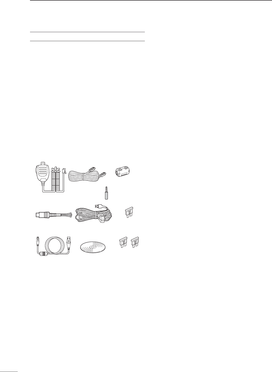
SUPPLIED ACCESSORIES
The following accessories are supplied with the transceiver.
q Hand microphone ............................................... 1
w Control cable ....................................................... 1
e Ferrite bead .......................................................... 1
r 3.5 (d) mm plug .................................................... 1
t ACC cable ............................................................ 1
y DC power cable* (OPC-1457) ............................ 1
or (OPC-1457R) ......................... 1
u Spare fuse (ATC 5 A) ......................................... 1
i USB cable ............................................................ 1
o CD ........................................................................ 1
!0 Spare fuse (ATC 30 A) ....................................... 2
* Depending on the version.
* Not supplied, or the shape is different, depending on the trans-
ceiver version.
qw e
r
t
io !0
yu

Front panel (Controller)...........................................................1-2
Display D .....................................................................................1-8
Display D .....................................................................................1-9
Display D .....................................................................................1-10
Display D .....................................................................................1-11
M-1 (M-1 menu) Display D ..........................................................1-11
M-2 (M-2 menu) Display D ..........................................................1-11
M-3 (M-3 menu) Display D ..........................................................1-11
D-1 (D-1 menu) Display D ........................................................... 1-11
D-2 (D-2 menu) Display D ........................................................... 1-11
1-1
Section 1PANEL DESCRIPTION
Previous view
1-1
Previous view
1PANEL DESCRIPTION
1-2
Previous view
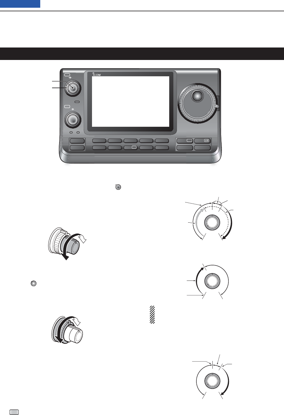
Front panel (Controller)
q POWER SWITCH/AF VOLUME [PWR]/[AF]
(p. 44)
Push to turn ON the transceiver power. ➥
• First, confi rm the DC power source is turned ON.
Hold down for 1 second to turn OFF the power. ➥
Rotate to adjust audio output level. ➥
Increases
Decreases
w RF GAIN CONTROL/ SQUELCH CONTROL
[RF/SQL] (p. 44)
Rotate to adjust the RF gain and squelch threshold
level.
The squelch removes noise output to the speaker
when no signal is received. (closed condition)
• The squelch is particularly effective for AM and FM, but
also works in other modes.
• The 12 to 1 o’clock position is recommended for the most
effective use of the [RF/SQL] control.
• [RF/SQL] operates as only an RF gain control in SSB,
CW and RTTY (Squelch is fi xed open), or a squelch con-
trol in AM, FM and DV (RF gain is fi xed at maximum sen-
sitivity), when “Auto” is selected as the “RF/SQL Control”
item in the “Function” Set mode. (p. 162)
SET
> Function > RF/SQL Control
• When used as an RF gain/squelch control
Maximum
RF gain
S-meter
squelch
Noise squelch (FM/DV modes)
Squelch is
open.
RF gain
adjustable
range
Recommended level
• When used as an RF gain control
(Squelch is fi xed open; SSB, CW and RTTY only)
Minimum RF gain
Adjustable
range
Maximum
RF gain
While rotating the RF gain control, a faint noise may
be heard. This comes from the DSP unit and does
not indicate an equipment malfunction.
• When used as a squelch control
(RF gain is fi xed at maximum.)
Squelch is
open.
S-meter
squelch
S-meter squelch
threshold
Noise squelch
threshold
(FM mode)
Shallow Deep
Noise squelch (FM/DV modes)
PBT RIT
TX / RX
PWR
AF RF/SQL
CLR
M-CH BANK
RIT
TUNER/CALL
MENU
MIC/RF PWR
NB
SPEED/PITCH
SET
QUICK
NOTCH
DR
AUTO
TUNE
RX
➔
CS
XFC
SPEECH
MPAD
NR
P.AMP
ATT
i7100
w
q
1PANEL DESCRIPTION
1-3
Previous view
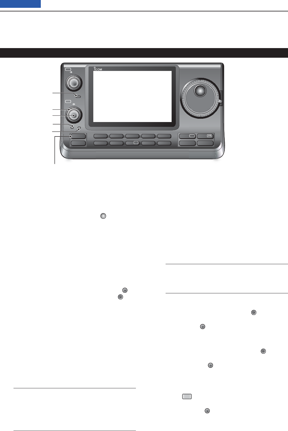
e TX/RX LED
Lights green when the squelch opens, or a signal ➥
is received.
Lights red during transmit. ➥
r MEMORY BANK CONTROL [BANK]
❍ When the both PBT and RIT LEDs are OFF
Rotate to select a Memory bank.
❍ When the PBT LED (y) rights green
(Mode: SSB/CW/RTTY/AM)
Rotate to adjust the receiver’s IF fi lter passband
width using the DSP circuit.
❍ When the RIT LED (u) rights orange
Disable this control.
t M-CH CONTROL/CLEAR KEY [M-CH]/[CLR]
Push to select the action of the [M-CH/BANK] con-
trols as the Memory/Bank selection, PBT control or
RIT control.
❍ When the both RIT and PBT LEDs are OFF
Rotate to select a Memory channel.
❍ When the RIT LED rights orange
➥ Rotate to adjust the RIT frequency shift.
• The frequency shift range is ±9.99 kHz in 10 Hz
steps. The control tunes in 1 Hz steps when the
operating frequency readout is set to the 1 Hz step
readout.
➥ Hold down for 1 second to clear the RIT shift
frequency.
✔ What is the RIT function?
The RIT (Receiver Incremental Tuning) shifts the re-
ceive frequency without shifting the transmit frequency.
This is useful for fi ne tuning stations calling you off-fre-
quency or when you prefer to listen to slightly different-
sounding voice characteristics, and so on.
❍ When the PBT LED rights green
(Mode: SSB/CW/RTTY/AM)
➥ Rotate to adjust the receiver’s IF fi lter pass-
band width using the DSP circuit.
➥
Hold down for 1 second to reset the PBT set-
tings.
• The PBT is adjustable in 50 Hz steps in the SSB/
CW/RTTY modes, and 200 Hz in the AM mode. In
this time, the shift value changes in 25 Hz steps in
the SSB/CW/RTTY modes, and 100 Hz in the AM
mode.
• The PBT controls function as an IF shift control.
✔ What is the PBT control?
The PBT function electronically modifi es the IF pass-
band width to reject interference. This transceiver uses
the DSP circuit for the PBT function.
y PBT LED
Lights green when the [M-CH/BANK] controls act
as the PBT control.
• Push the [M-CH] switch to select as the PBT control.
u RIT LED
Lights orange when the RIT function turns ON. ➥
Lights orange when the [M-CH/BANK] ➥ controls
act as the RIT control.
• Push the [M-CH] switch to select as the RIT con-
trol.
• The RIT control is the inner control. The outer control
is disabled.
i RIT KEY
RIT
(p. 69)
Push to turn the RIT function ON or OFF. ➥
• Use the [M-CH] control to vary the RIT frequency.
➥ Hold down for 1 second to add the shift frequency
of the RIT function to or subtract it from the dis-
played frequency.
Front panel (Controller) (Continued)
PBT RIT
TX / RX
PWR
AF RF/SQL
CLR
M-CH BANK
RIT
TUNER/CALL
MENU
MIC/RF PWR
NB
SPEED/PITCH
SET
QUICK
NOTCH
DR
AUTO
TUNE
RX
➔
CS
XFC
SPEECH
MPAD
NR
P.AMP
ATT
i7100
t
e
r
y
u
i
1PANEL DESCRIPTION
1-4
Previous view
o ANTENNA TUNER/CALL KEY
TUNER/CALL
❍ ANTENNA TUNER KEY Operation (p. 139)
(Frequency band: HF/50 MHz)
➥ Push to turn the optional antenna tuner ON or
OFF (bypass).
➥ Hold down for 1 second to manually start the
antenna tuner.
• If the tuner cannot tune the antenna within 20 sec-
onds, the tuning circuit is automatically bypassed.
❍ CALL KEY Operation (p. 139)
(Frequency band: 144/430 MHz)
Push to select the call channel.
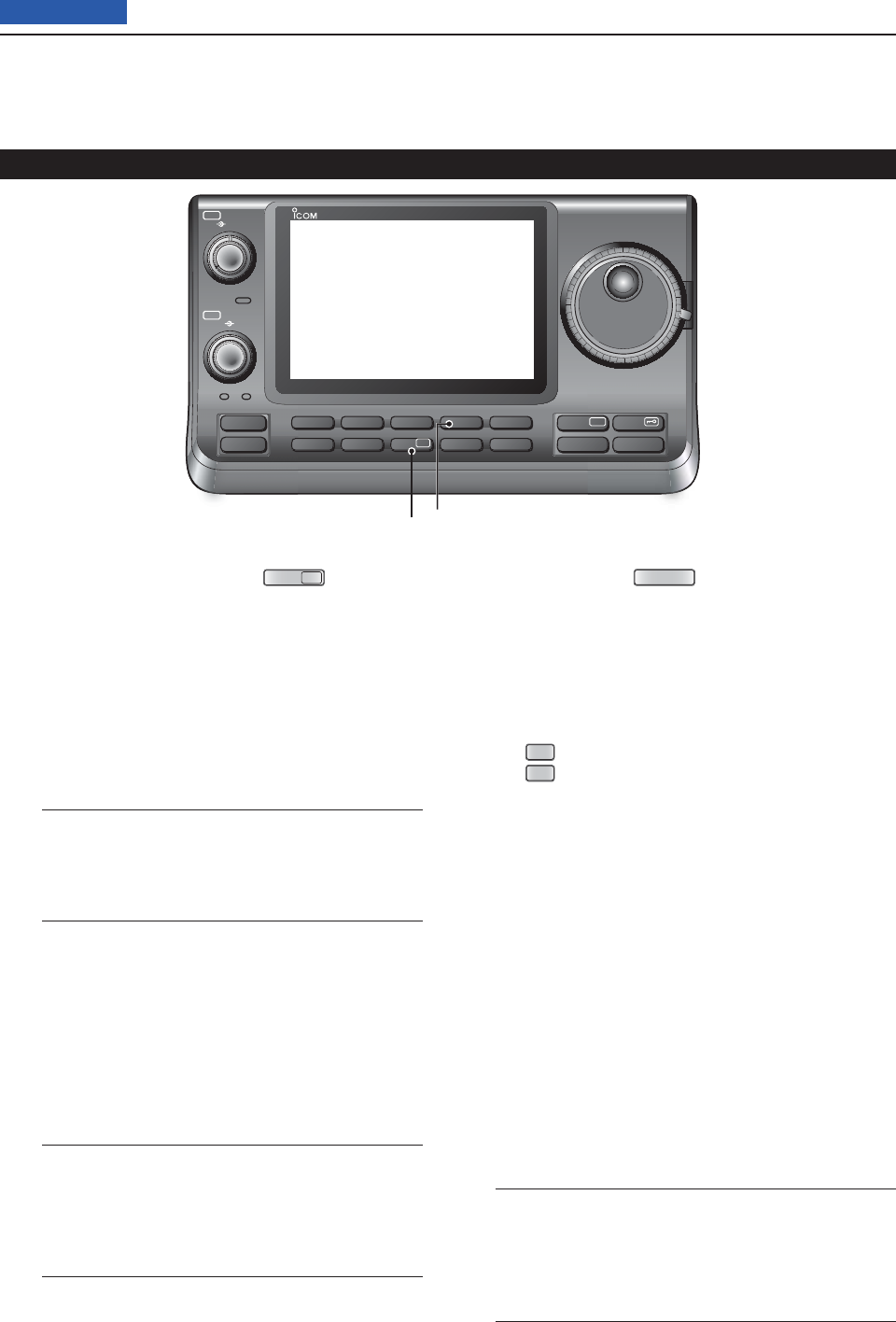
!0 MENU SWITCH
MENU
(p. 19)
Push to change the set of functions assigned to
touch keys.
• Toggles the function display menu between M-1 (M-1
menu), M-2 (M-2 menu), M-3 (M-3 menu), D-1 (D-1
menu) and D-2 (D-2 menu).
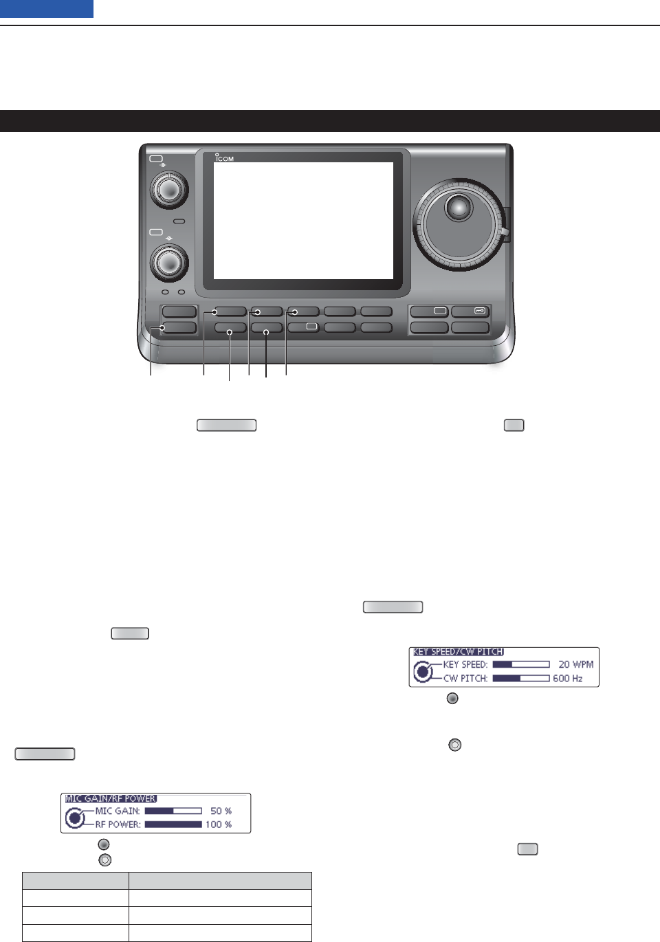
!1 MIC GAIN/RF POWER ADJUSTMENT KEY
MIC/RF PWR
(p. 19)
Push to open the MIC gain/RF power adjustment
display.
• Rotate [M-CH] to adjust the MIC gain.
• Rotate [BANK] to adjust the RF power.
Frequency band RF output power range
HF/50 MHz 2 to 100 W (AM: 1 to 30 W)
144 MHz 2 to 100 W
430 MHz 2 to 75 W
• Push again to close the window.
!2 NOISE BLANKER KEY
NB
(p. 76)
(Mode: SSB/CW/RTTY/AM)
Push to turn the noise blanker ON or OFF. ➥
The noise blanker reduces pulse-type noise such
as that generated by vehicle ignition systems. The
noise blanker is not effective for non-pulse-type
noise.
• “NB” appears when the noise blanker is ON.
Hold down for 1 second to display the “NB” screen. ➥
Push to return to the previous screen.
!3 KEY SPEED/CW PITCH ADJUSTMENT KEY
SPEED/PITCH
(p. 19)
Push to open the Key speed/CW pitch adjustment
display.
• Rotate [M-CH] to adjust the keying speed of the inter-
nal electronic CW keyer to between 6 wpm (minimum)
and 48 wpm (maximum).
• Rotate [BANK] to shift the received CW audio pitch
and the CW sidetone pitch without changing the operat-
ing frequency.
• The CW pitch can be adjusted from 300 to 900 Hz in ap-
proximately 5 Hz steps.
• Push again to close the window.
!4 NOISE REDUCTION KEY
NR
(p. 77)
Push to turn DSP noise reduction ON or OFF. ➥
• “NR” appears when noise reduction is ON.
Hold down for 1 second to display the “NR” screen. ➥
Push to return to the previous screen.
• Rotate the Dial to adjust the DSP noise reduction
level. Set for maximum readability.
Front panel (Controller) (Continued)
PBT RIT
TX / RX
PWR
AF RF/SQL
CLR
M-CH BANK
RIT
TUNER/CALL
MENU
MIC/RF PWR
NB
SPEED/PITCH
SET
QUICK
NOTCH
DR
AUTO
TUNE
RX
➔
CS
XFC
SPEECH
MPAD
NR
P.AMP
ATT
i7100
o!0 !2 !4!1 !3
1PANEL DESCRIPTION
1-5
Previous view
!5 PREAMP•ATTENUATOR KEY
P.AMP
ATT
❍ PREAMP KEY Operation (p. 71)
(Frequency band: HF/50 MHz)
Push to select one of two receive RF preampli-
fi ers, or to bypass them.
• “P. AMP1” is a wide dynamic range preamplifi er. It is
most effective for the 1.8 to 21 MHz bands.
• “P. AMP2” is a high-gain preamplifi er. It is most effec-
tive for the 24 to 50 MHz bands.
• No indicator appears when the preamplifi ers are not
selected.
✔ What is the preamplifi er?
The preamplifi er amplifi es signals in the front end
to improve the S/N ratio and sensitivity. Select “P.
AMP1” or “P. AMP2” when receiving weak sig-
nals.
(Frequency band: 144/430 MHz)
Push to turn the preamplifi er ON or OFF.
• “P.AMP” appears when the preamplifi er is ON.
❍ ATTENUATOR KEY Operation (p. 71)
➥ Hold down for 1 second to turn ON the attenu-
ator.
• “ATT” appears when the attenuator is ON.
➥ Push to turn OFF the attenuator.
• “ATT” disappears.
✔ What is the attenuator?
The attenuator prevents a desired signal from be-
ing distorted when very strong signals are near it,
or when very strong electromagnetic fi elds, such
as from a broadcasting station, are near your lo-
cation.
!6 NOTCH SWITCH
NOTCH
(p. 77)
(Mode = Auto notch: SSB/AM/FM
Manual notch: SSB/CW/RTTY/AM)
➥In the SSB and AM modes, push to toggle the
notch function between auto, manual and OFF.
• Either the Auto or Manual notch function can be turned
OFF in
the “[NOTCH] Switch (SSB)/(AM)” items
of the
“Function” Set mode. (p. 36)
SET
> Function > [NOTCH] Switch (SSB)
SET
> Function > [NOTCH] Switch (AM)
➥In the FM mode, push to turn the Auto Notch func-
tion ON or OFF.
➥ In the CW or RTTY mode, push to turn the Manual
Notch function ON or OFF.
• “MN” appears when the Manual Notch function is
ON.
• “AN” appears when the Auto Notch function is ON.
• No indicator appears when the notch fi lter is OFF.
➥ Hold down for 1 second to display the “NOTCH”
screen.
Push to return to the previous screen.
• Rotate the Dial to adjust the notch frequency to reject
an interfering signal while the manual function is ON.
• Notch fi lter center frequency:
SSB/RTTY: –1040 Hz to +4040 Hz
CW: CW pitch frequency –2540 Hz to
CW pitch frequency +2540 Hz
AM: –5060 Hz to +5100 Hz
✔ What is the notch fi lter?
The notch fi lter is a narrow fi lter that eliminates un-
wanted CW or AM carrier tones, while preserving
the desired voice signal. The DSP circuit automati-
cally adjusts the notch frequency to effectively elimi-
nate unwanted tones.
Front panel (Controller) (Continued)
PBT RIT
TX / RX
PWR
AF RF/SQL
CLR
M-CH BANK
RIT
TUNER/CALL
MENU
MIC/RF PWR
NB
SPEED/PITCH
SET
QUICK
NOTCH
DR
AUTO
TUNE
RX
➔
CS
XFC
SPEECH
MPAD
NR
P.AMP
ATT
i7100
!6!5

1PANEL DESCRIPTION
1-6
Previous view
!7 DR MODE KEY
DR
(p. 85)
➥ Push to select the DR mode.
• When DR mode is selected, the transceiver automati-
cally selects the DV mode.
➥ In the DR mode, push to cancel it.
• The transceiver returns to the previous screen before
entering the DR mode.
!8 SET MODE KEY
SET
(p. 85)
➥ Push to enter or exit the SET mode.
• “Voice Memo,” “Call Sign,” “RX History,” “DV Memory,”
“My Station,” “DV Set,” “GPS,” “SPEECH,” “QSO/RX
Log,” “Function,” “Tone Control,” “Connector,” “Dis-
play,” “Time Set,” “SD Card” and “Others” set group
are available.
!9 QUICK MENU KEY
QUICK
(p. 85)
➥ Push to open to close the Quick Menu window.
• The Quick Menu is used to quickly select various
functions.
➥ In the setting screen, hold down for 1 second to
open the Default set window.
• Touch “Default” to reset to the default setting.
@0 AUTOTUNE/RXCS KEY
AUTO TUNE
RXCS
(p. 85)
❍ AUTOTUNE KEY Operation (p. 71)
(Mode: CW)
➥ Push to automatically adjust for a zero beat
with the received signal.
Zero beat means that two signals are exactly the
same frequency.
• “AUTO TUNE” blinks when auto tune function is
activated.
• When the RIT function is ON, the auto tune func-
tion changes the RIT frequency, not the displayed
frequency.
❍ RX CALL SIGN CAPTURE KEY Operation
(p. 71)
(Mode: DV, when the DR mode is selected)
➥ Push to open the “RX>CS” screen.
Push again to retune to the previous screen.
➥ Hold down for 1 second to set the received call
signs (station and repeaters) as the operating
call sign.
@1
TRANSMIT FREQUENCY CHECK KEY
XFC
➥ During split frequency or repeater operation, hold
down to listen to the transmit frequency. (p. 82)
• While holding down this switch, the transmit frequen-
cy can be changed with the Dial or
MPAD
.
• When the Split Lock function is turned ON, hold down
XFC
to cancel the Dial lock function. (pp. 82, 162)
➥ When the RIT function is turned ON, hold down to
listen to the receive frequency. (RIT is temporarily
cancelled.) (p. 69)
➥ In the simplex operation, hold down to monitor the
receive frequency.
• While holding down this key, the squelch is opened
and the interference reject function is temporary OFF.
➥ In the DV mode, the RX monitoring mode is se-
lected by holding down this key. (p. 118)
Front panel (Controller) (Continued)
PBT RIT
TX / RX
PWR
AF RF/SQL
CLR
M-CH BANK
RIT
TUNER/CALL
MENU
MIC/RF PWR
NB
SPEED/PITCH
SET
QUICK
NOTCH
DR
AUTO
TUNE
RX
➔
CS
XFC
SPEECH
MPAD
NR
P.AMP
ATT
i7100
!8 @0!7 @1!9
1PANEL DESCRIPTION
1-7
Previous view
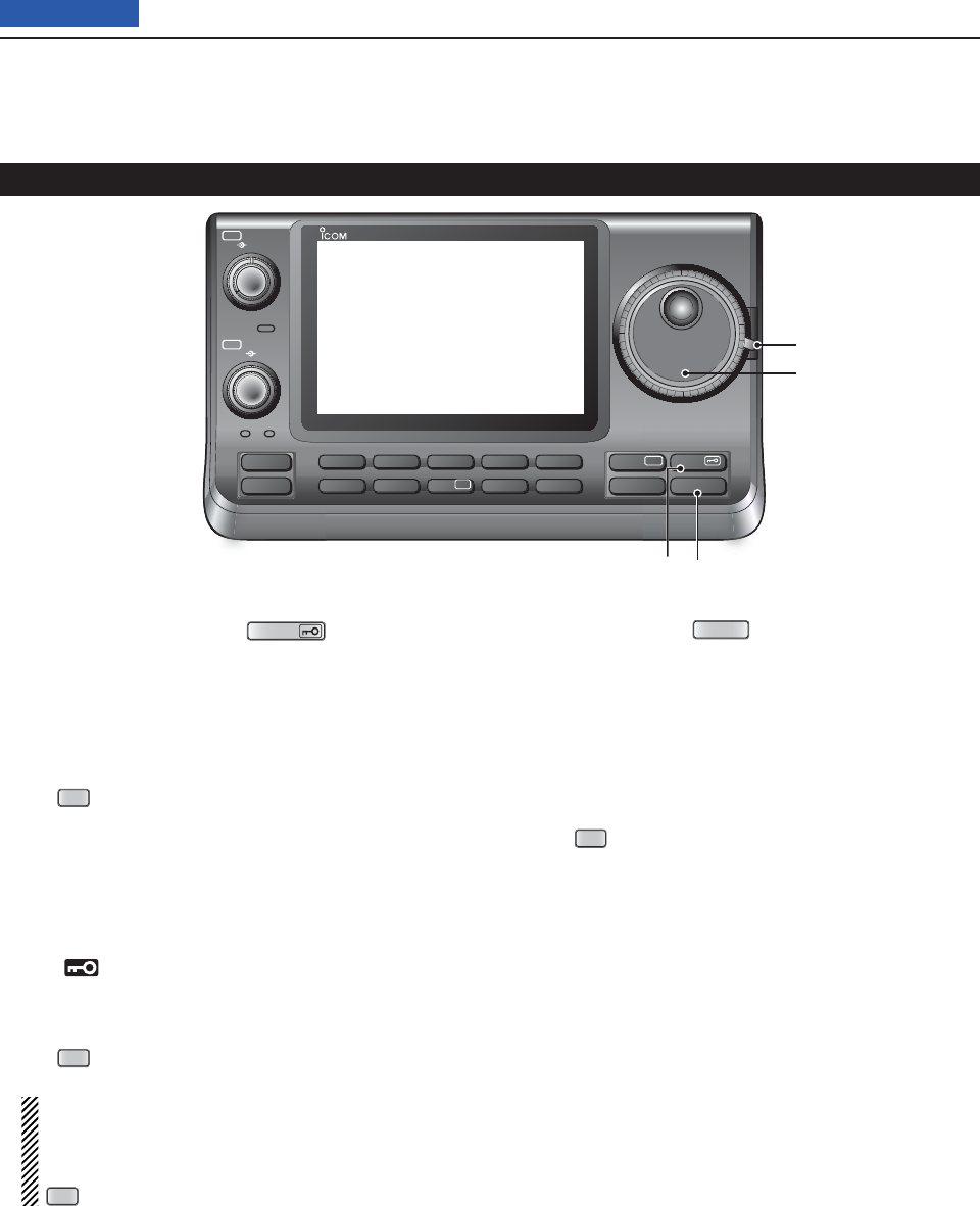
@2 SPEECH/LOCK SWITCH
SPEECH
❍ SPEECH KEY Operation (p. 45)
Push to audibly announce the S-meter level, the
displayed frequency and the operating mode.
• The S-Level announcement can be turned OFF in the
“S-Level SPEECH” item of the “SPEECH” Set mode.
(p. 164)
SET
> SPEECH > S-Level SPEECH
• When RIT is ON, the RIT offset is not included in the
frequency announcement.
❍ LOCK KEY Operation (p. 77)
Hold down for 1 second to turn the Lock function
ON or OFF.
• The function electronically locks the Dial.
• “ ” appears when the function is ON.
• The function can be select the Dial lock and Panel
lock in the “Lock Function” item of the “Function” Set
mode. (p. 164)
SET
> Function > Lock Function
NOTE: The [SPEECH/LOCK] switch operation to
activate the voice synthesizer or the Lock func-
tions can be replaced in the “[SPEECH/LOCK]
Switch” item of the “Function” Set mode. (p. 164)
SET
> Function > Lock Function
@3 MEMO PAD KEY
MPAD
(p. 144)
Push to sequentially call up the contents from the ➥
memo pads.
The 5 (or 10) most recently programmed frequen-
cies and operating modes can be recalled, start-
ing from the most recent.
• The memo pad capacity can be increased from 5 to
10 in
the “Memopad Numbers” item
of the “Function”
Set mode (p. 164)
SET
> Function > Memopad Numbers
Hold down for 1 second to write the displayed ➥
data into a memo pad.
• The 5 most recent entries remain in the memo pads.
@4 MAIN DIAL
Rotate to change the displayed frequency, select the
Set mode settings, and so on.
@5 MAIN DIAL TENSION LATCH
Select the Dial drag.
• Three positions are selectable. The upper side setting
turns on clicks as the dial is turned.
Front panel (Controller) (Continued)
PBT RIT
TX / RX
PWR
AF RF/SQL
CLR
M-CH BANK
RIT
TUNER/CALL
MENU
MIC/RF PWR
NB
SPEED/PITCH
SET
QUICK
NOTCH
DR
AUTO
TUNE
RX
➔
CS
XFC
SPEECH
MPAD
NR
P.AMP
ATT
i7100
@2 @3
@4
@5
1PANEL DESCRIPTION
1-8
Previous view
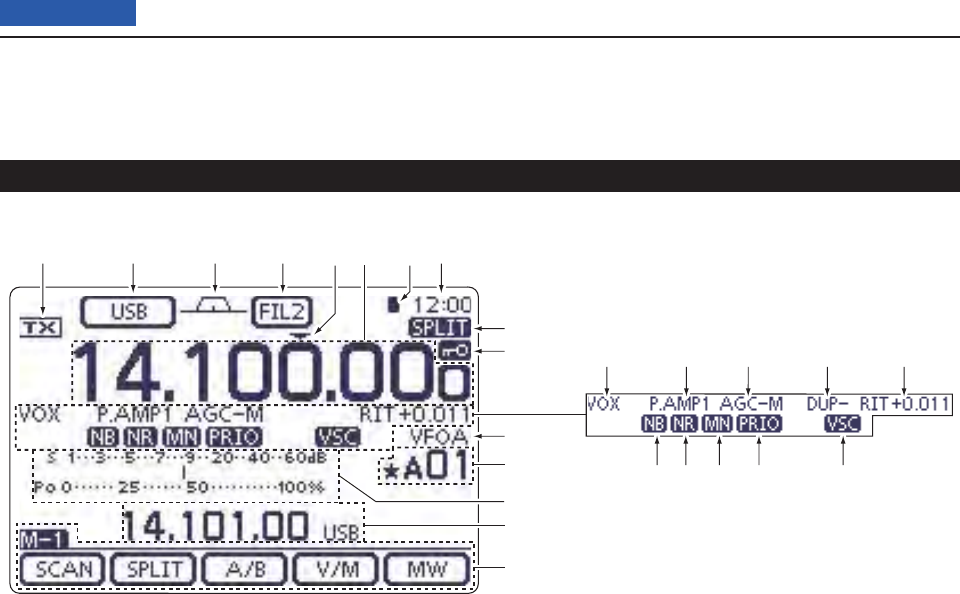
Front panel (Controller) (Continued)
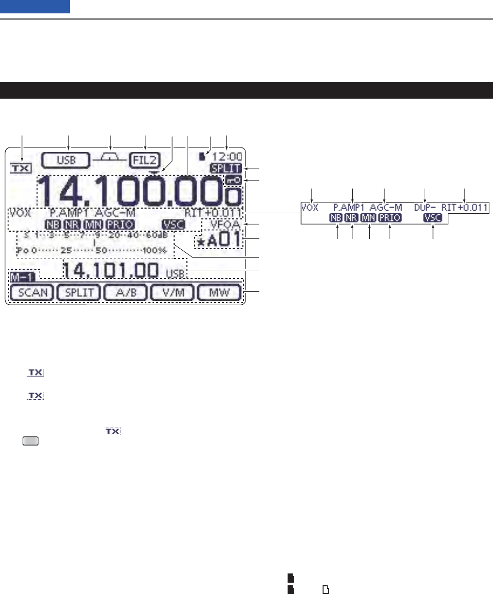
q TX ICON
Indicates either the displayed frequency can be
transmitted, or not.
➥ “” appears while the operating frequency is in
an amateur band.
➥ “” appears while the operating frequency is
not in an amateur band. However, when the “Band
Edge Beep” item is set to “OFF” in the “Function”
Set mode (p. 85), “ ” does not appear.
SET
> Function > Band Edge Beep
“LMT” appears while the output power is de- ➥
creased due to the Power FET’s temperature is
high.
“HOT” appears while the transmission is inhibited ➥
due to the Power FET’s temperature is too high.
w MODE ICONS (p. 43)
Displays the selected operating mode. ➥
• “-D” appears when SSB data, AM data or FM data
mode is selected.
Touch to enter the Mode selection screen. ➥
• On the Mode selection screen, touch the block to se-
lect the operating mode.
e PASSBAND WIDTH ICON (p. 75, 77)
Graphically displays the passband width for twin
PBT operation and center frequency for IF shift op-
eration.
r IF FILTER ICON (p. 75, 77)
Shows the selected IF fi lter. ➥
Touch to select one of three IF fi lter settings. ➥
• The selected fi lter passband width and shifting value
are displayed for 2 seconds on the window.
➥ Touch for 1 second to display the “FILTER” screen
(Filter) to adjust the fi lter passband width.
➥
When the “FILTER” screen is displayed, touch for
1 second to return to the previous screen.
t QUICK TUNING ICON
Appears when the Quick tuning mode is selected.
• When “Z” is displayed, the frequency changes in pre-set
kHz or 1 MHz quick tuning steps. (p. 38)
• When “Z” is not displayed, the frequency changes in 10
Hz or 1 Hz steps. (pp. 37, 39)
y FREQUENCY READOUTS
Displays the operating frequency. ➥
Touch the MHz digits to enter the Band selection ➥
screen.
Touch the MHz digits for 1 second to turn the 1 ➥
MHz quick tuning mode ON or OFF.
Touch the kHz digits to turn the pre-set kHz quick ➥
tuning mode ON or OFF.
Touch the kHz digits for 1 second to enter the Tun- ➥
ing step selection screen.
Touch the Hz digits to for 1 second to toggle be- ➥
tween 10 Hz and 1 Hz steps.
u SD CARD ICON
➥ “” appears when an SD card is inserted.
➥ “” and “ ” alternately blinks while accessing the
SD card.
i CLOCK READOUT
Shows the current time.
• UTC time or local time can be selected.
o SPLIT ICON (p. 82)
Appears when the Split function is turned ON.
o LOCK INDICATOR (p. 37)
Appears when the Lock function is activated.
!0 LOCK ICON (p. 77)
Appears when the Lock function is turned ON.
qywertui
o
!0
@1
@2
@3
@4
@5
!1 !2 !3 !5!4
!6!7!8!9@0
Display D
1PANEL DESCRIPTION
1-9
Previous view
!0 1⁄4 TUNING DIAL SPEED ICON (p. 39)
(Mode: SSB-D/CW/RTTY)
“1/4” appears when the tuning dial speed is set so
that one rotation is equal to 1⁄4 of the normal rota-
tion.
• This function is available only when the quick tuning
function is turned OFF.
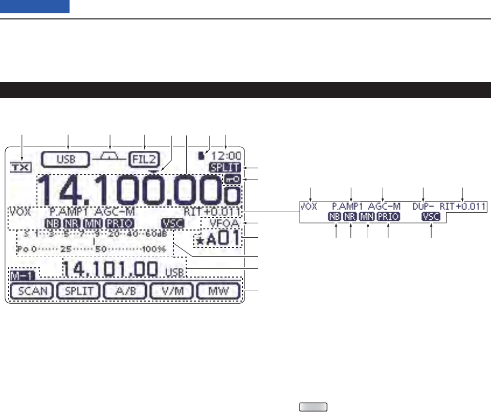
!1 VOX ICON (p. 78)
Appears when the VOX function is activated.
!2 PREAMP ICON (p. 71)
Appears when a preamplifi er is turned ON.
• In HF/50 MHz frequency band, either “P.AMP1” or
“P.AMP2” is displayed when the preamp 1 or preamp 2
is ON.
• In 144/430 MHz frequency band, “P.AMP” is displayed
when the preamp is ON.
!2 ATTENUATOR ICON (p. 71)
Appears when the Attenuator function is turned
ON.
!3 AGC ICONS (p. 72)
Displays the selected AGC time constant.
• “AGC-F” for AGC fast; “AGC-M” for AGC middle; “AGC-S”
for AGC slow; “AGC-OFF” for AGC OFF.
• In the FM, WFM and DV mode, “AGC-F” for AGC fast is
fi xed.
!4 DUPLEX ICON (p. 65)
“DUP+” appears when plus duplex, “DUP –” appears
when minus duplex (repeater) operation is selected.
!5 RIT ICON (pp. 69, 81)
➥ “RIT” appears when the RIT function is turned
ON.
➥ Shows the shift frequency of the RIT function.
!6 VOICE SQUELCH CONTROL ICON (p. 146)
Appears when the VSC (Voice Squelch Control)
function is turned ON.
!7 PRIORITY WATCH INDICATOR (p. 113)
Appears while priority scan is activated.
!8 NOTCH ICONS (p. 77)
(Mode: SSB/CW/RTTY/AM)
➥ “MN” appears when the Manual Notch function is
turned ON.
(Mode: SSB/AM/FM)
➥ “AN” appears when the Automatic Notch function
is turned ON.
!9 NOISE REDUCTION ICON (p. 77)
Appears when the Noise Reduction function is
turned ON.
@0 NOISE BLANKER ICON (p. 76)
Appears when the Noise Blanker function is turned
ON.
@1 VFO/MEMORY ICONS (p. 34)
“VFOA” or “VFOB” appears whether VFO A or ➥
VFO B is selected.
“MEMO” appears when the memory mode is se- ➥
lected.
Front panel (Controller) (Continued)
qywertui
o
!0
@1
@2
@3
@4
@5
!1 !2 !3 !5!4
!6!7!8!9@0
Display D
1PANEL DESCRIPTION
1-10
Previous view
Front panel (Controller) (Continued)
qywertui
o
!0
@1
@2
@3
@4
@5
!1 !2 !3 !5!4
!6!7!8!9@0
Display D
@2 MEMORY CHANNEL READOUT (p. 100)
Shows the selected memory channel, scan edge ➥
channel or Call channel.
• Memory bank indicator (A to E) appears to the left of
memory channel.
Touch to toggle between the VFO and Memory ➥
modes.
@2 SELECT MEMORY CHANNEL ICON
“” appears when the selected memory channel is
set as a select memory channel.
(p. 151)
@3 MULTI-FUNCTION METER INDICATION
➥ Displays the signal strength while receiving.
➥ Displays the relative output power, SWR, ALC or
compression levels while transmitting.
➥ When the Meter Peak Hold function is ON, the
peak level of a received signal strength or the
output power is displayed for approximately 0.5
seconds.
➥ Touch to select the RF power, SWR, ALC or Com-
pression meter.
➥ Touch for 1 second to display the Multi-function
meter.
@4 INFORMATION READOUT (p. 80)
Displays the transmit frequency of the Split opera-
tion, descriptions of the memory channel or Re-
ceived Call sign on the DV mode, and so on.
@5 FUNCTION DISPLAY (p. 19)
Shows the function of the Touch keys.
• Push
MENU
to change the set of functions assigned to
touch keys.
• Toggles the function display menu between M-1 (M-1
menu), M-2 (M-2 menu), M-3 (M-3 menu), D-1 (D-1
menu) and D-2 (D-2 menu).
1PANEL DESCRIPTION
1-11
Previous view
Front panel (Controller) (Continued)
Display D
Push ➥
MENU
to change the set of functions assigned
to touch keys.
• Toggles the function display menu between M-1 (M-1
menu), M-2 (M-2 menu), M-3 (M-3 menu), D-1 (D-1
menu) and D-2 (D-2 menu).
• Functions vary, depending on the operating mode.
• In the DR mode, the D-1 (D-1 menu) and D-2 (D-2 menu)
can be selected.
Touch or touch for 1 second to select the displayed ➥
functions.
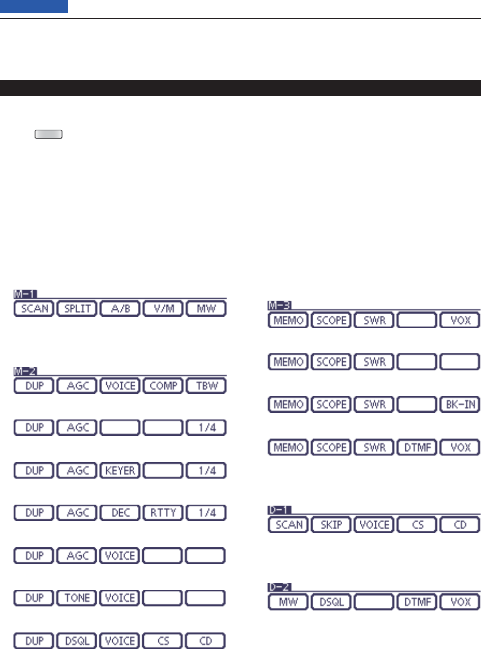
M-1 (M-1 menu) Display D
M-2 (M-2 menu) Display D
(Mode: SSB)
(Mode: SSB-D)
(Mode: CW)
(Mode: RTTY)
(Mode: AM/AM-D)
(Mode: FM/FM-D/WFM)
(Mode: DV)
M-3 (M-3 menu) Display D
(Mode: SSB/AM/AM-D)
(Mode: SSB-D/RTTY)
(Mode: CW)
(Mode: FM/FM-D/WFM/DV)
D-1 (D-1 menu) Display D
(Mode: DV, when the DR mode is selected)
D-2 (D-2 menu) Display D
(Mode: DV, when the DR mode is selected)

1PANEL DESCRIPTION
1-12
Previous view
D Function keys on M-1 display
SCAN KEY [SCAN] (p. 147)
Touch to display the “SCAN” screen.
SPLIT SWITCH [SPLIT] (p. 82)
➥ Touch to turn the split function ON or OFF.
• “SPLIT” appears when the split function is ON.
➥ Touch for 1 second to activate the quick split func-
tion.
• The transmit frequency shifts from the receive frequency
according to the “SPLIT Offset” option in the Set mode.
(p. 162)
• The quick split function can be turned OFF in
the “Quick
SPLIT” item
of the Set mode. (p. 162)
VFO SELECT SWITCH [A/B] (pp. 32, 34)
➥ Touch to select either VFO A or VFO B.
➥ Touch
for 1 second to equalize the undisplayed VFO
settings to that of the displayed VFO.
VFO/MEMORY SWITCH [V/M]
➥ Touch to switch between the VFO and memory
modes. (pp. 34, 139)
• Touching Memory channel also selects the VFO or mem-
ory modes. (p. 162)
➥ Touch for 1 second to copy the memory contents to
the displayed VFO on the MAIN Band. (p. 142)
MEMORY WRITE SWITCH [MW] (p. 140)
Touch for 1 second to store VFO data into the selected
memory channel.
• This can be done in both the VFO and memory modes.
D Function keys on M-2 display
DUPLEX KEY [DUP] (p. 65)
➥ Touch to select the duplex direction, or to turn OFF
the function.
• “DUP–” or “DUP+” is displayed during duplex operation.
➥ In the FM mode, touch for 1 second to turn the one-
touch repeater function ON or OFF.
AGC KEY [AGC] (p. 72)
(Mode: SSB/SSB-D/CW/RTTY/AM/AM-D)
➥ Touch to select the time constant of the AGC circuit.
➥ Touch for 1 second to display the “AGC” screen.
TONE SQUELCH KEY [TONE] (pp. 62–64)
(Mode: FM)
➥ Touch to select a tone function between subaudible
(repeater) tone, tone squelch and DTCS code.
➥ Touch for 1 second to display the “TONE” screen of
the selected tone function.
DIGITAL SQUELCH KEY [DSQL] (p. 114)
(Mode: DV)
➥ Push to select a digital squelch function between
digital call sign squelch and digital code squelch.
➥ Hold down for 1 second to display the “DSQ” screen
(digital squelch).
MEMORY KEYER MENU KEY [KEYER] (p. 50)
(Mode: CW)
Push to display the
“
KEY
”
screen (memory keyer) or the
“
SEND
”
screen (keyer send), depending on the “KEYER
1st Menu” option in the Set mode
(p. 165)
.
SPEECH COMPRESSOR KEY [COMP] (p. 80)
(Mode: SSB)
➥ Touch to turn the speech compressor function ON
or OFF.
• “COMP” is displayed when the speech compressor is
ON.
➥ Touch for 1 second to display the “COMP” screen.
RTTY MENU KEY [RTTY] (p. 57)
Touch to display the “RTTY” screen.
CALL SIGN KEY [CS](F-1) (p. 85)
(Mode: DV)
Touch to display the “CS” screen.
• The current call sign for DV operation appears.
TRANSMISSION BANDWIDTH KEY [TBW] (p. 80)
(Mode: SSB)
➥ Touch to display the selected
transmission band-
width.
➥ Touch for 1 second
to select the transmission band-
width.
• Bandwidth is selectable from wide (WIDE), middle (MID)
and narrow (NAR).
1⁄4 TUNING FUNCTION KEY [1⁄4] (p. 39)
(Mode: SSB-D/CW/RTTY)
Touch to turn the 1⁄4 Tuning function ON or OFF.
• “ ” is displayed when the 1⁄4 Tuning function is ON.
CALL RECORD KEY [CD] (p. 95)
(Mode: DV)
Touch to display the “CD” screen.
• The call record channel appears. (RX01 to RX20)

Operating SSB .........................................................................4-2
Operating CW ...........................................................................4-3
About the CW reverse mode D ...................................................4-4
About keying speed D .................................................................4-4
About CW pitch control D............................................................4-4
CW sidetone function D ..............................................................4-5
CW Auto tune function D ............................................................4-5
Electronic keyer functions ......................................................4-6
Memory keyer menu construction D ...........................................4-6
Memory keyer send menu D .......................................................4-7
Editing a memory keyer D ...........................................................4-8
Contest number Set mode D ......................................................4-9
Keyer Set mode D .......................................................................4-10
Operating RTTY (FSK) .............................................................4-12
The functions for RTTY operation..........................................4-13
About RTTY reverse mode D ......................................................4-13
Twin Peak Filter D .......................................................................4-13
RTTY Set mode D .......................................................................4-14
RTTY decoder D .........................................................................4-15
RTTY decode Set mode D ..........................................................4-16
Transmitting an RTTY memory D ................................................4-17
Editing an RTTY memory D ........................................................4-18
Turning ON the RTTY decode log D ...........................................4-19
RTTY decode log Set mode D ....................................................4-20
Operating AM/FM .....................................................................4-21
Tone squelch operation ..........................................................4-22
DTCS operation .......................................................................4-23
Tone scan/DTCS code scan operation ..................................4-24
Repeater operation ..................................................................4-25
Repeater access tone frequency setting D .................................4-26
One-touch repeater function D....................................................4-27
Transmit frequency monitor check D ........................................... 4-28
1750 Hz tone burst D ..................................................................4-28
Turning ON the Auto Repeater function D
(U.S.A. and Korea versions only) .............................................4-29
Storing a non standard repeater D ............................................4-30
4-1
Section 4RECEIVE AND TRANSMIT
Previous view
4RECEIVE AND TRANSMIT
4-2
Previous view
Select the desired frequency band. (p. 35) q
On the Mode selection screen, touch “SSB” to select w
the LSB or USB mode.
• When operating above 10 MHz, USB is selected fi rst;
when operating below 10 MHz, LSB is selected fi rst.
• After selecting LSB or USB, touch “SSB” again to toggle
between USB and LSB modes, if necessary.
• To select the data mode, after selecting LSB or USB,
touch “DATA” to select the data mode, if needed.
Rotate the Dial to tune a desired signal. e
• The S-meter displays the received signal strength.
•
The tuning step can be changed on the Tuning step selec-
tion screen by touching “kHz frequency.” (p. 38)
Rotate [AF] r(L)to adjust the audio to a comfort-
able listening level.
Push [PTT] on the microphone to transmit. t
• The TX/RX indicator lights red.
Speak into the microphone at your normal voice y
level.
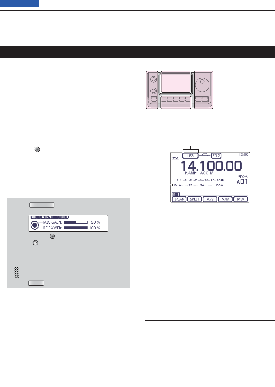
If necessary, adjust the microphone gain or RF pow- u
er on the Mic gain/RF power adjustment display.
q Push
MIC/RF PWR
(C) to open the MIC gain/RF
power adjustment display.
w Rotate [M-CH] (L) to adjust the MIC gain, or
[BANK] (L) to adjust the RF power.
• To adjust the MIC gain, touch the TX meter to select
the ALC meter. And then, adjust it so that the ALC
meter reading stays within the ALC zone.
When the MIC gain is adjusted too high, your
transmitted voice may be distorted.
e Push
MENU
(C) to close the display.
Release [PTT] to receive. i
Operating SSB
Convenient Receive functions
• Preamp and attenuator (p. 71)
• Twin PBT (passband tuning) (p. 75)
• AGC (auto gain control) (p. 72)
• Noise blanker (p. 76)
• Noise reduction (p. 77)
• Notch fi lter (p. 77)
• Receive fi lter width (HPF/LPF) (p. 169)
• Tone control (p. 169)
Convenient Transmit functions
• Speech compressor (p. 78)
• VOX (voice operated transmit) (p. 80)
• Transmit quality monitor (p. 81)
• Transmit fi lter width (p. 80)
• Tone control (p. 169)
The L, R, C or D in the
instructions indicate the
part of the controller.
L: Left side
R: Right side
C: Center bottom
D: Display (Touch panel)
Left Right
Center
Display
“LSB” or “USB” appears
TX meter
4RECEIVE AND TRANSMIT
4-3
Previous view
Operating CW
Select the desired frequency band. (p. 35) q
On the Mode selection screen, touch “CW” to select w
the CW mode.
• After the CW mode is selected, touch “CW” again to tog-
gle between CW and CW-R modes, if necessary.
Rotate the Dial to tune a desired signal. e
• The S-meter displays the received signal strength.
• The tuning step can be changed on the Tuning step se-
lection screen by touching “kHz frequency.” (p. 38)
Rotate [AF] r(L) to adjust the audio to a comfort-
able listening level.
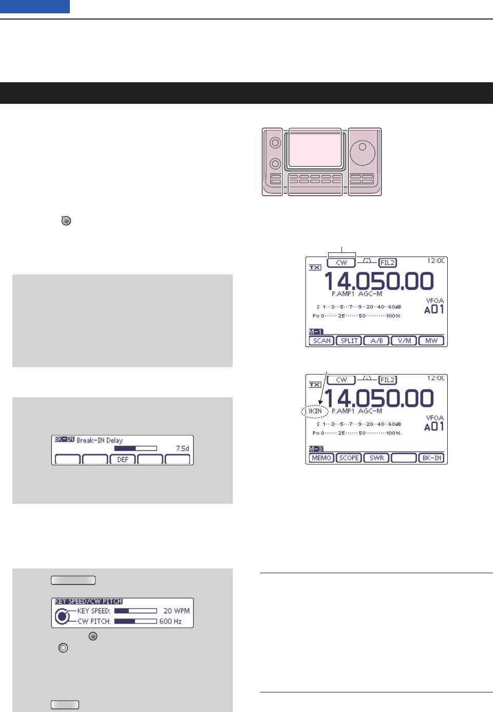
Set the Break-in operation to the semi break-in or full t
break-in mode.
• “BKIN,” “F-BKIN” or “OFF (no indication)” appears.
While the “M-3” menu is selected, touch [BK-IN](D)
once or twice to select the Break-in operation.
• BKIN : Semi break-in
• F-BKIN : Full break-in
• OFF : No break-in (ACC socket connection for TX
is necessary, as shown on page 22.)
If a microphone is connected, its PTT can be
used instead of the external TX switch.
If the Semi break-in operation is selected at step yt,
set the Break-in delay.
q While the “M-3” menu is selected, touch
[BK-IN](D) for 1 second to open the Break-in
delay adjustment window.
w Rotate the Dial to adjust the delay time.
• The adjustable delay time is between 2.0 and 13.0
dots.
Use the electric keyer or paddle to key your CW sig- u
nals.
• The TX/RX indicator lights red.
•
The Po meter indicates transmitted CW output power.
If desired, adjust the Key speed or CW pitch. i
q Push
SPEED/PITCH
(C) to open the Key speed/CW
pitch adjustment window.
w Rotate [M-CH] (L) to adjust the Key speed, or
[BANK] (L) to the CW pitch.
• The adjustable key speed is between 6 and 48 wpm
(words per minute).
• The adjustable CW pitch is between 300 and 900
Hz.
e Push
MENU
(C) to close the window.
Stop keying to return to receive. o
Convenient Receive functions
• Preamp and attenuator (p. 71)
• Twin PBT (passband tuning) (p. 75)
• AGC (auto gain control) (p. 72)
• Noise blanker (p. 76)
• Noise reduction (p. 77)
• Manual Notch fi lter (p. 77)
• ¼ function (p. 39)
• CW pitch control (p. 49)
Convenient Transmit functions
• Break-in function (p. 79)
• Keying speed setting (p. 49)
• Memory keyer (p. 50)
The L, R, C or D in the
instructions indicate the
part of the controller.
L: Left side
R: Right side
C: Center bottom
D: Display (Touch panel)
Left Right
Center
Display
“CW” or “CW-R” appears
Semi break-in operation is selected
Appears
4RECEIVE AND TRANSMIT
4-4
Previous view
Operating CW (Continued)
About the CW reverse mode D
The CW reverse mode receives signals with a reverse
side CW carrier point similar to voice LSB and USB
modes.
Use when interfering signals are near a desired signal
and you want to reduce the interfering tone.
On the Mode selection screen, touch “CW” to select q
the CW mode.
After the CW mode is selected, touch “CW” again on w
the Mode selection screen to toggle between CW
and CW-R modes.
• Check that the interfering tone can be reduced.
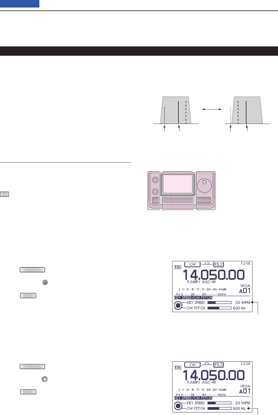
About keying speed D
The transceiver’s internal electronic keyer speed can
be adjusted to between 6 and 48 wpm (words per min-
ute).
Push q
SPEED/PITCH
(C) to open the Key speed/CW pitch
adjustment display.
Rotate [M-CH] w(L) clockwise to increase keying
speed; counterclockwise to decrease it.
Push e
MENU
(C) to close the display.
About CW pitch control D
The received CW audio pitch can be adjusted to suit
your preference without changing the operating fre-
quency.
Push q
SPEED/PITCH
(C) to open the Key speed/CW pitch
adjustment display.
Rotate [BANK] w(L) to suit your preference.
• Adjustable from 300 to 900 Hz (in 5 Hz steps).
Push e
MENU
(C) to close the display.
Key speed adjustment
CW pitch adjustment
Carrier point
The CW carrier point is set to the LSB side by default,
the setting can be changed to USB side in the “CW
Normal Side” item of the “Function” Set mode. (p. 165)
SET
(C) > Function > CW Normal Side
The L, R, C or D in the
instructions indicate the
part of the controller.
L: Left side
R: Right side
C: Center bottom
D: Display (Touch panel)
Left Right
Center
Display
BFO
CW-R mode (USB side)
BFO
Desired signal
CW mode (LSB side)
Interference Desired signalInterference
4RECEIVE AND TRANSMIT
4-5
Previous view
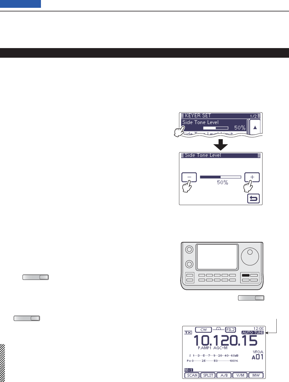
CW Auto tune function D
The automatic tuning function automatically tunes the
displayed frequency when an off-frequency signal is
received. This function is active while in the CW mode
is selected.
Push ➥
AUTO TUNE
RXCS
(R) to automatically adjust for a
zero beat with the received signal.
Zero beat means that two signals are exactly the same
frequency.
• “AUTO TUNE” blinks when auto tune function is activat-
ed.
• If
AUTO TUNE
RXCS
(R) is pushed when the RIT function is ON,
the auto tune function changes the RIT frequency, not
the displayed frequency.
IMPORTANT!
When receiving a weak signal, or receiving a signal with
interference, the automatic tuning function may tune the
receiver to an undesired signal.
If the off-frequency signal is too far away, the Auto tune func-
tion may not work. In that case, an error beep sounds.
AUTO TUNE icon
CW sidetone function D
When the transceiver is in the receive mode (and the
Break-in function is OFF— p. 79), you can listen to the
CW sidetone without actually transmitting.
You can also use the CW sidetone to practice CW send-
ing, but be sure to turn OFF the Break-in function.
The CW sidetone level can be adjusted in the “Side
Tone Level” item of the Keyer Set mode (p. 54).
Operating CW (Continued)
AUTO TUNE
RXCS
4RECEIVE AND TRANSMIT
4-6
Previous view
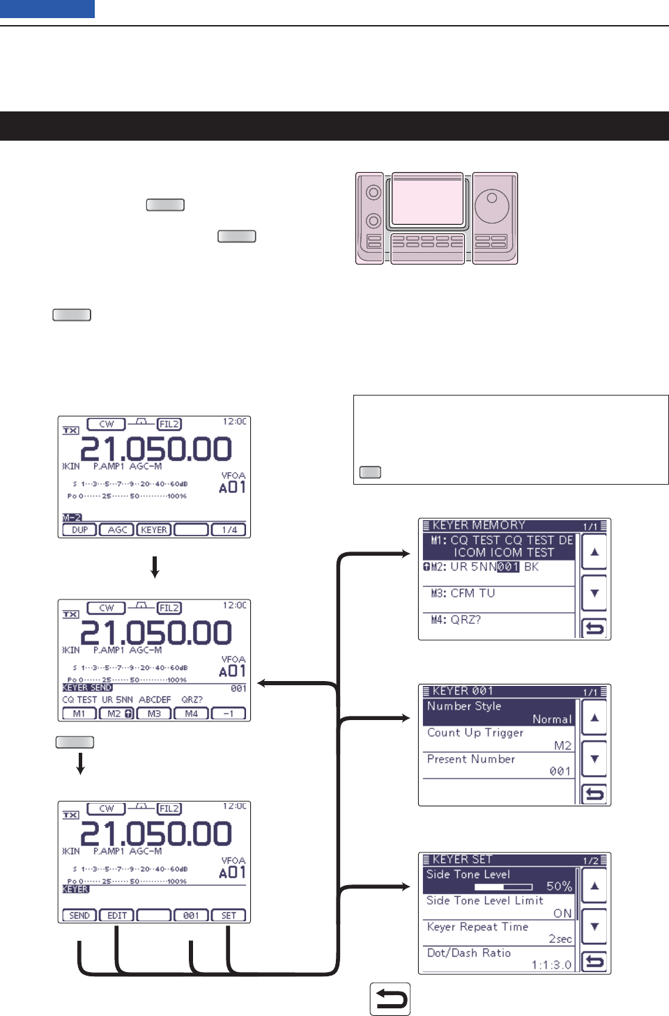
Electronic keyer functions
You can access a number of convenient built-in elec-
tronic keyer functions in the memory keyer menu.
q
In the CW mode,
push
MENU
(C) one or more times
to select the “M-2” screen (M-2 menu).
Touch [KEYER]( wD), and then push
MENU
(C) to dis-
play the “KEYER” screen (Memory Keyer).
Touch [SEND], [EDIT], [001] or [SET]( eD) to select
the desired menu.
See the diagram below.
• Push
MENU
(C) to return to the previous display.
• Keyer (Root) screen
• Keyer Send screen (p. 51)
• Keyer Memory (Edit) screen (p. 52)
• Keyer 001 (Contest number Set) screen (p. 53)
• Keyer Set screen (p. 54)
[KEYER]
[SEND]
[EDIT]
: Returns to the previous display.
[001]
[SET]
[SEND]
[EDIT]
[001]
[SET]
Memory keyer menu construction D
The screen you want to appear fi rst can be selected
in the “KEYER 1st Menu” item of the “Function” Set
mode. (p. 165)
SET
(C) > Function > KEYER 1st Menu
Push
MENU
The L, R, C or D in the
instructions indicate the
part of the controller.
L: Left side
R: Right side
C: Center bottom
D: Display (Touch panel)
Left Right
Center
Display
4RECEIVE AND TRANSMIT
4-7
Previous view
Electronic keyer functions (Continued)
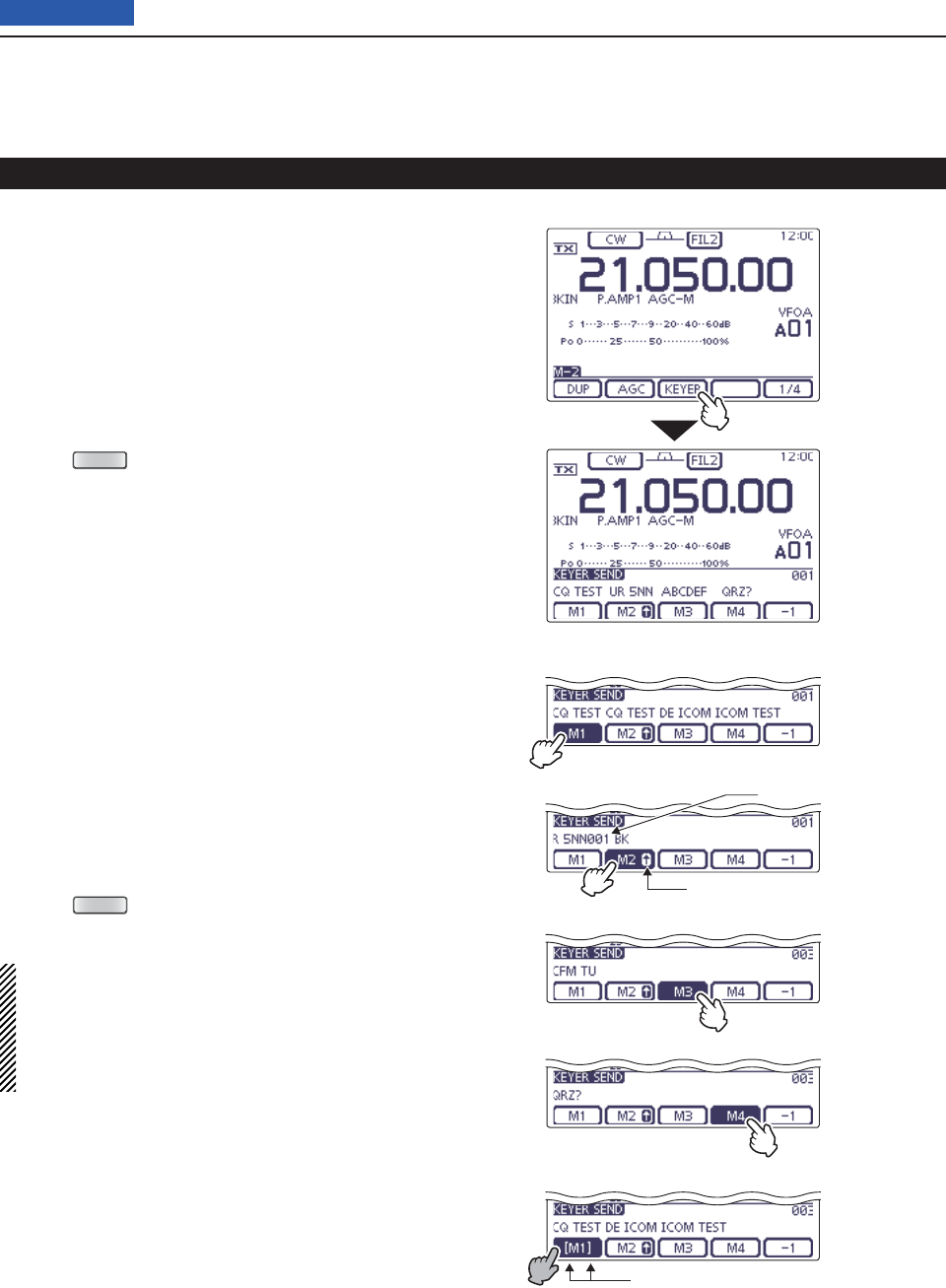
Memory keyer send menu D
Preset characters can be sent using the Keyer Send
screen. Contents of the memory keyer are enterd in the
Keyer Memory (Edit) screen.
• Transmitting
q
In the CW mode,
turn ON the Break-in function. (p.
79)
• When the Break-in function is OFF and you do step r,
you can listen the memory keyer contents without trans-
mitting.
Push w
MENU
(C) one or more times to select the
“M-2” screen (M-2 menu).
Touch [KEYER]( eD) to display the “KEYER SEND”
screen.
• If the “KEYER” (Root) screen is displayed, touch
[SEND](D) to display the “KEYER SEND” screen.
Touch one of the Memory keys, [M1] to [M4]( rD), to
send the memory keyer contents.
• Touch a Memory key for 1 second to repeatedly send the
contents; touch any Memory key to stop the transmis-
sion.
• Set the repeat interval to between 1 and 60 seconds (1
second steps) in the “Keyer Repeat Time” item of the
“KEYER SET” screen. (p. 54)
• “M1”– “M4” are highlighted while transmitting.
• The contest number counter advances each time the
contents are sent.
• Push [−1](D) to reduce the contest number advances by
one before sending the memory keyer contents to a sta-
tion a second time.
Push t
MENU
(C) to return to the “KEYER” (Root)
screen.
For your information
When an external keypad is connected to pin 3 and
pin 7 of the [MIC] connector, the contents of M1 to
M4 can be transmitted without selecting the “KEYER
SEND” screen.
See page 167 for details.
• M1 sending display
• M2 sending display
• M3 sending display
• M4 sending display
• While transmitting repeatedly
Counter
Count up trigger icon
“ [ ” and “ ] ” appear
Touch [KEYER]
4RECEIVE AND TRANSMIT
4-8
Previous view
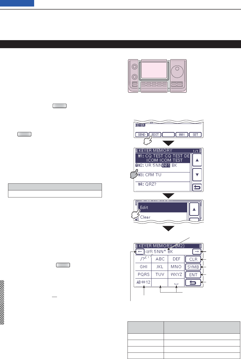
Editing a memory keyer D
The contents of the memory keyer memories can be
set on the Keyer Memory (Edit) screen. The memory
keyer can memorize and retransmit 4 CW key codes for
often-used CW sentences, contest numbers or a count
up trigger. The total capacity of the memory keyer is 70
characters per memory channel.
• Programming contents
q
In the CW mode,
push
MENU
(C) one or more times
to select the “M-2” screen (M-2 menu).
Touch [KEYER]( wD) to display the “KEYER SEND”
screen.
• If the “KEYER” (Root) screen is displayed, skip step e.
Push e
MENU
(C) to display the “KEYER” screen.
Touch [EDIT]( rD) to display the “KEYER MEMORY”
(Edit) screen.
• The memory contents are displayed.
Touch for 1 second on a desired memory channel to t
be edited, and then touch “Edit.”
• The memory programming screen appears.
Touch the desired block one or more times to select y
the desired character, number or symbol.
Selectable characters, numbers and symbols
A to Z, 0 to 9, ⁄ ? ^ . , @ ✱
• Touch “AB12” to toggle between the Alphabet input
and Number input mode.
• Touch [CLR](D) to delete the selected character, symbol
or number.
• Touch [SYMB](D) to open the Symbol character selec-
tion window.
• Touch “” to input a space.
Touch [ u](D) or [](D) to move the cursor back-
wards or forwards.
i Repeat steps y and u to program up to 70 charac-
ters of memory contents, and then push [ENT](D).
o Touch [](D) or push
MENU
(C) to return to the
“KEYER” (Root) screen.
NOTE:
“^” is used to transmit a string of characters with no
inter-character space. Put a “^” before a text string such
as ^AR, and the string “
AR
” is sent with no space.
“✱” is used to insert the CW contest number. The number
automatically advances by 1. This function is available for
only one memory keyer channel at a time. “✱” is used in
memory keyer channel M2 by default.
• Preprogrammed memory keyer contents
Memory keyer
channel Contents
M1 CQ TEST CQ TEST DE JA1 JA1 TEST
M2 UR 5NN✱ BK
M3 CFM TU
M4 QRZ?
Electronic keyer functions (Continued)
“KEYER” (Root) screen
• Memory keyer programming mode
The L, R, C or D in the
instructions indicate the
part of the controller.
L: Left side
R: Right side
C: Center bottom
D: Display (Touch panel)
Left Right
Center
Display
Touch the desired
channel for 1 sec-
ond
Touch “Edit”
Touch [EDIT]
• M2 default indication
When inputting an asterisk, the
counter is incremented by 1.
Input a space
Select Alphabet or Number input
Move the cursor
Move the cursor
Delete a character
Select a Symbol
Enter
Cancel edit
4RECEIVE AND TRANSMIT
4-9
Previous view
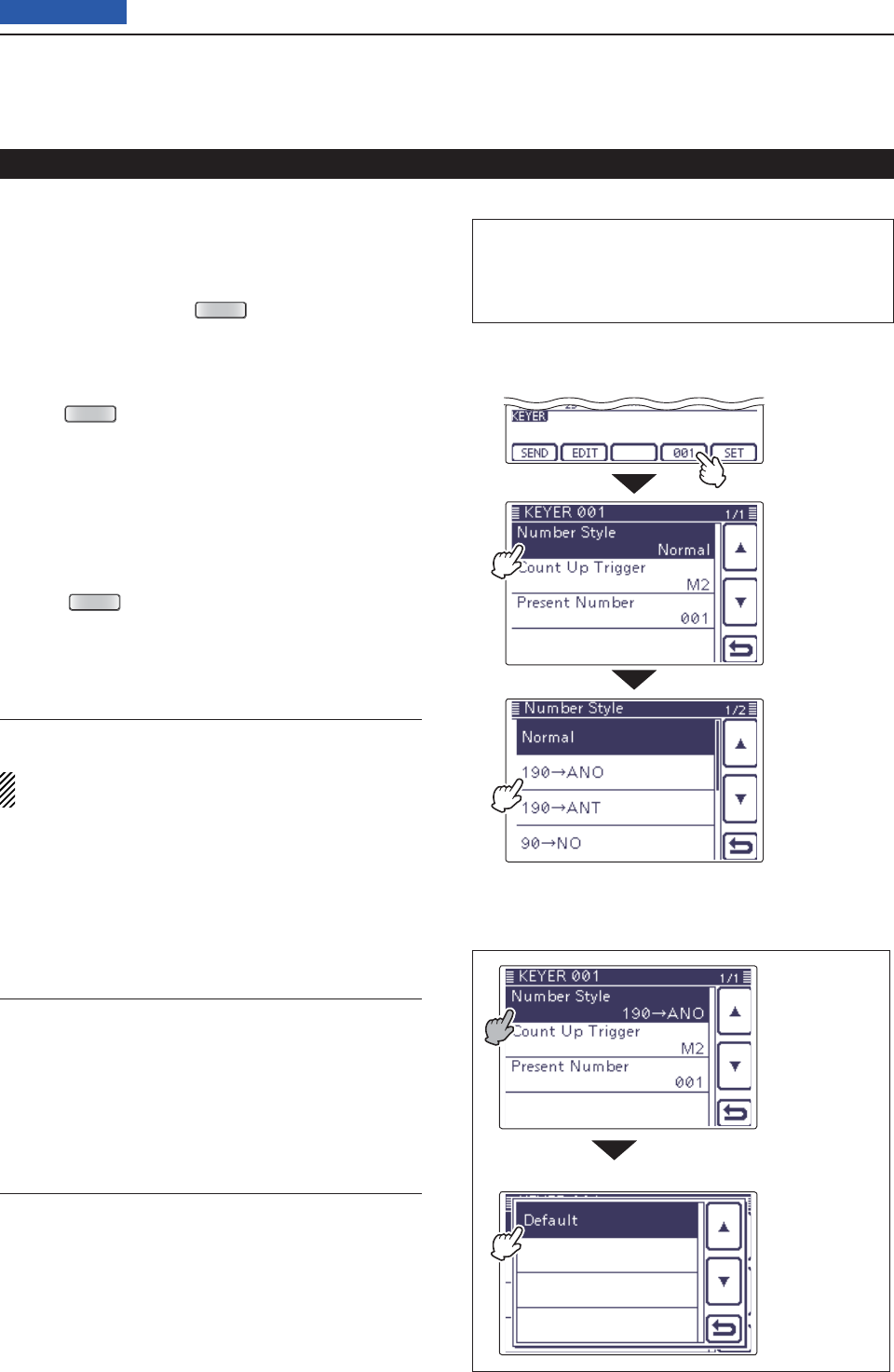
Contest number Set mode D
This mode is used to set the contest number, count up
trigger and Present number.
• Setting contents
q
In the CW mode, p
ush
MENU
(C) one or more times
to select the “M-2” screen (M-2 menu).
w Push [KEYER](D) to display the “KEYER SEND”
screen.
• If the “KEYER” (Root) screen is displayed, skip step e.
Push e
MENU
(C) to display the “KEYER” screen.
Push [001]( rD) to enter the “KEYER 001” (Contest
Number Set) screen.
Touch the desired item to select. t
Touch the ydesired option or rotate the Dial to change
the setting.
• If desired, touch the item for 1 second to open the Default
set window, then select “Default” to reset to the default
setting.
Push u
MENU
(C) to return to the “KEYER” (Root)
screen.
Electronic keyer functions (Continued)
“KEYER” (Root) screen
• Contest number Set mode
Number Style (Default: Normal)
This item sets the numbering system used for contest
numbers— normal or short morse numbers.
Short morse numbers are also referred to as “cut”
numbers.
• Normal: Does not use short morse numbers
• 190➔ANO: Sets 1 as A, 9 as N and 0 as O.
• 190➔ANT: Sets 1 as A, 9 as N and 0 as T.
• 90➔NO: Sets 9 as N and 0 as O.
• 90➔NT: Sets 9 as N and 0 as T.
Count Up Trigger (Default: M2)
Set the count-up trigger to one of four memory slots for
the contest number exchange. The count-up trigger al-
lows the contest number to automatically advance after
each complete number exchange is sent.
• M1, M2, M3 or M4 can be set.
Present Number (Default: 001)
This item shows the current number for the count-up
trigger channel set above.
• Touch [+] or [–](D) or rotate the Dial to change the
number.
• Hold down the item for 1 second to display the default
set window, then touch “Default” to set the counter to
“001.”
• To the default setting
• Default set window
The L, R, C or D in the instructions indicate the
part of the controller.
L: Left side, R: Right side, C: Center bottom
D: Display (Touch panel)
Touch [001]
Touch the item
for 1 second.
Touch “Default.”
Touch the item
( Example: Num-
ber Style)
Touch the option
( Example:
190➔ANO)
4RECEIVE AND TRANSMIT
4-10
Previous view
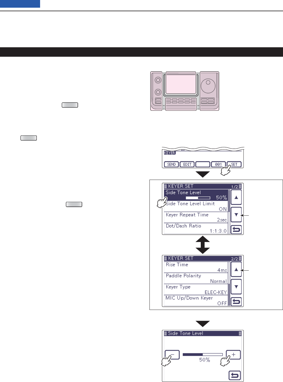
Keyer Set mode D
This Set mode is used to set the CW sidetone, memory
keyer repeat time, dash weight, paddle specifi cations,
keyer type, and so on.
• Setting contents
q
In the CW mode, p
ush
MENU
(C) one or more times
to select the “M-2” screen (M-2 menu).
w Push [KEYER](D) to display the “KEYER SEND”
screen.
• If the “KEYER” (Root) screen is displayed, skip step e.
Push e
MENU
(C) to display the “KEYER” screen.
Touch [SET]( rD) to enter the “KEYER SET” screen.
Touch the desired item to select. t
• See the next page for details of the set items and op-
tions.
Touch the ydesired option or rotate the Dial to change
the value.
• If desired, touch the item for 1 second to open the De-
fault set window, then select the “Default” to reset to the
default setting.
Touch [ u](D) or push
MENU
(C) to return to the
“KEYER” (Root) screen.
Electronic keyer functions (Continued)
“KEYER” screen (Memory Keyer)
• Keyer Set mode
Touch [SET]
The L, R, C or D in the
instructions indicate the
part of the controller.
L: Left side
R: Right side
C: Center bottom
D: Display (Touch panel)
Left Right
Center
Display
Returns to the
previous page
Moves to the
next page
(Example: Touch the “Side Tone Level.”)
4RECEIVE AND TRANSMIT
4-11
Previous view
Side Tone Level (Default: 50%)
Select the CW sidetone output level.
• 0 to 100% can be selected.
Side Tone Level Limit (Default: ON)
Set the CW sidetone level limit. When the [AF] (L)
control is rotated above a specifi ed level, the CW
sidetone does not increase.
• OFF: CW sidetone level is not limited.
• ON: CW sidetone level is limited.
Keyer Repeat Time (Default: 2sec)
When sending CW using the repeat timer, set the time
between transmissions.
• 1 to 60 seconds in 1 second steps can be selected.
Dot/Dash Ratio (Default: 1:1:3.0)
Set the dot/dash ratio.
• 1:1:2.8 to 1:1:4.5 (in 0.1 steps) can be selected.
Keying weight example: Morse code “K”
DASH
Weight setting:
1:1:3 (default)
Weight setting:
Adjusted
DASH
DOT (fixed*)
Adjustable range SPACE (fixed*)
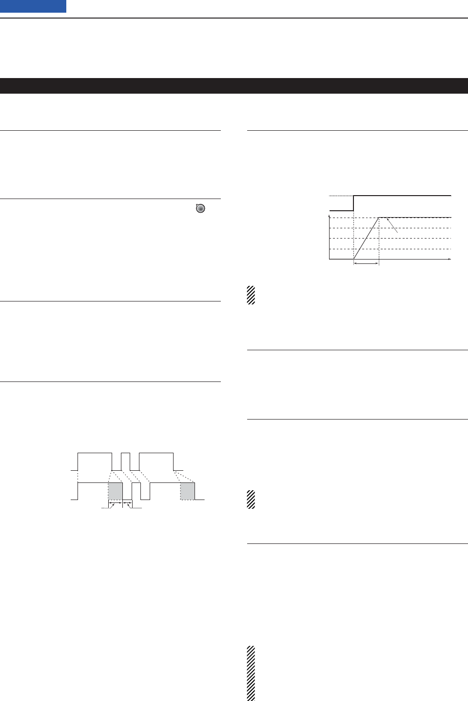
Rise Time (Default: 4ms)
Set the rise time of the transmitted CW envelope.
• 2, 4, 6 or 8 milliseconds can be selected.
About rise time
Key action
Tx output power
Rise time
Tx
Rx
Set Tx power level
Time
0
Key clicks on nearby frequencies can be generated if
the rise time of a CW waveform is too short.
Paddle Polarity (Default: NORMAL)
Set the paddle polarity.
• Normal or reverse polarity can be selected.
Keyer Type (Default: ELEC-KEY)
Select the keyer type for [ELEC-KEY] connector on the
controller.
• Straight key, BUG-KEY or ELEC-KEY can be select-
ed.
Regardless of this setting, the [KEY] connector of
the Main unit is for only a straight key.
MIC Up/Down Keyer (Default: OFF)
Set the microphone [UP]/[DN] switches to be used as
a key. (The microphone [UP]/[DN] switches do not work
as a “squeeze key.”)
• ON: The [UP]/[DN] switches can be used as a key
for CW.
• OFF: The [UP]/[DN] switches cannot be used as a
key for CW.
• When “ON” is selected, the frequency and memory
channels cannot be changed using the [UP]/[DN]
switches.
• The optional HM-151 microphone cannot be used
as a MIC Up/Down Keyer.
Electronic keyer functions (Continued)
Keyer set mode (Continued) D
* SPACE and DOT length can be adjusted on the
Key Speed/CW pitch adjustment display.
4RECEIVE AND TRANSMIT
4-12
Previous view
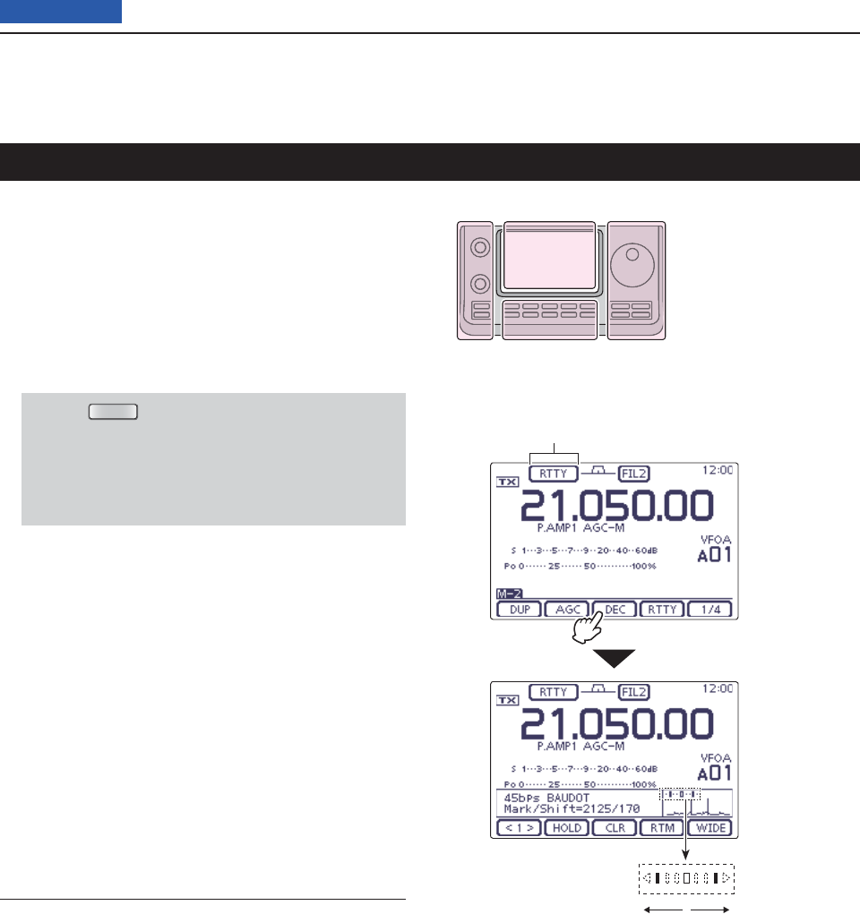
When using your RTTY terminal or TNC, consult the
manual that comes with the equipment.
Select the desired frequency band. (p. 35) q
On the Mode selection screen, touch “RTTY” to se- w
lect the RTTY mode.
• After the RTTY mode is selected, touch “RTTY” again to
toggle between the normal and reverse modes, if need-
ed.
Enter the RTTY decoder screen. e
q Push
MENU
(C) one or more times to select the
“M-2” screen (M-2 menu).
w Touch [DEC](D) to display the RTTY decoder
screen.
• Touch [WIDE](D) to toggle the decode screen size
between normal and wide.
Rotate the Dial to tune a desired signal. r
• The S-meter displays the received signal strength.
• If the received signal cannot be demodulated, try to se-
lect the RTTY reverse mode in step w.
• The tuning step can be changed on the Tuning step se-
lection screen by touching “kHz frequency.” (p. 38)
Switch ON the external TX switch to set the trans- t
ceiver to the transmit mode, or transmit a SEND sig-
nal from your TNC.
• The TX/RX indicator lights red.
•
The Po meter displays the transmitted
RTTY signal
strength.
Use your connected PC or TNC (TU) to transmit y
RTTY (FSK) signals.
Switch OFF the external TX switch to receive. u
Convenient Receive functions
• Preamp and attenuator (p. 71)
• Twin PBT (passband tuning) (p. 75)
• AGC (auto gain control) (p. 72)
• Noise blanker (p. 76)
• Noise reduction (p. 77)
• Notch fi lter (p. 77)
• ¼ function (p. 39)
• Twin Peak Filter (p. 58)
Operating RTTY (FSK)
The L, R, C or D in the
instructions indicate the
part of the controller.
L: Left side
R: Right side
C: Center bottom
D: Display (Touch panel)
Left Right
Center
Display
“RTTY” or “RTTY-R” appears
Touch [DEC]
Rotate the Dial to the point where both
sides of the dots equally appear.
4RECEIVE AND TRANSMIT
4-13
Previous view
The functions for RTTY operation
About RTTY reverse mode D
Received characters are occasionally garbled when
the Mark and Space signals are reversed. This reversal
can be caused by incorrect TNC connections, setting
or commands.
To correctly receive reversed RTTY signals, select the
RTTY reverse mode.
On the Mode selection screen, touch “RTTY” to se- q
lect the RTTY mode.
After the RTTY mode is selected, touch “RTTY” again w
on the Mode selection screen, toggles between the
normal and reverse modes.
• “RTTY-R” appears when the RTTY reverse mode is se-
lected.
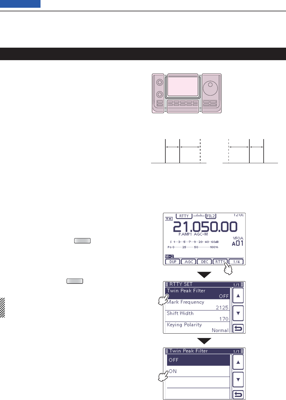
Twin Peak Filter D
The Twin Peak Filter changes the receive frequency re-
sponse by boosting 2125 and 2295 Hz for better copy-
ing of RTTY signals.
In the RTTY mode, push q
MENU
(C) one or more
times to select the “M-2” screen (Menu M-2).
Touch [RTTY]( wD) to display the “RTTY SET”
screen.
Touch the “Twin Peak Filter” item to select. e
Touch “ON” to turn ON the Twin Peak Filter. r
Touch [ t](D) or push
MENU
(C) to return to the
“M-2” screen (Menu M-2).
NOTE: When the Twin Peak Filter is in use, the re-
ceived audio output may increase. This is normal;
not a malfunction.
Normal Reverse
170 Hz170 Hz 2125 Hz2125 Hz
BFOBFO Space
Space Mark
Mark
The L, R, C or D in the
instructions indicate the
part of the controller.
L: Left side
R: Right side
C: Center bottom
D: Display (Touch panel)
Left Right
Center
Display
Touch [RTTY]
Touch “Twin
Peak Filter”
Touch “ON”
4RECEIVE AND TRANSMIT
4-14
Previous view
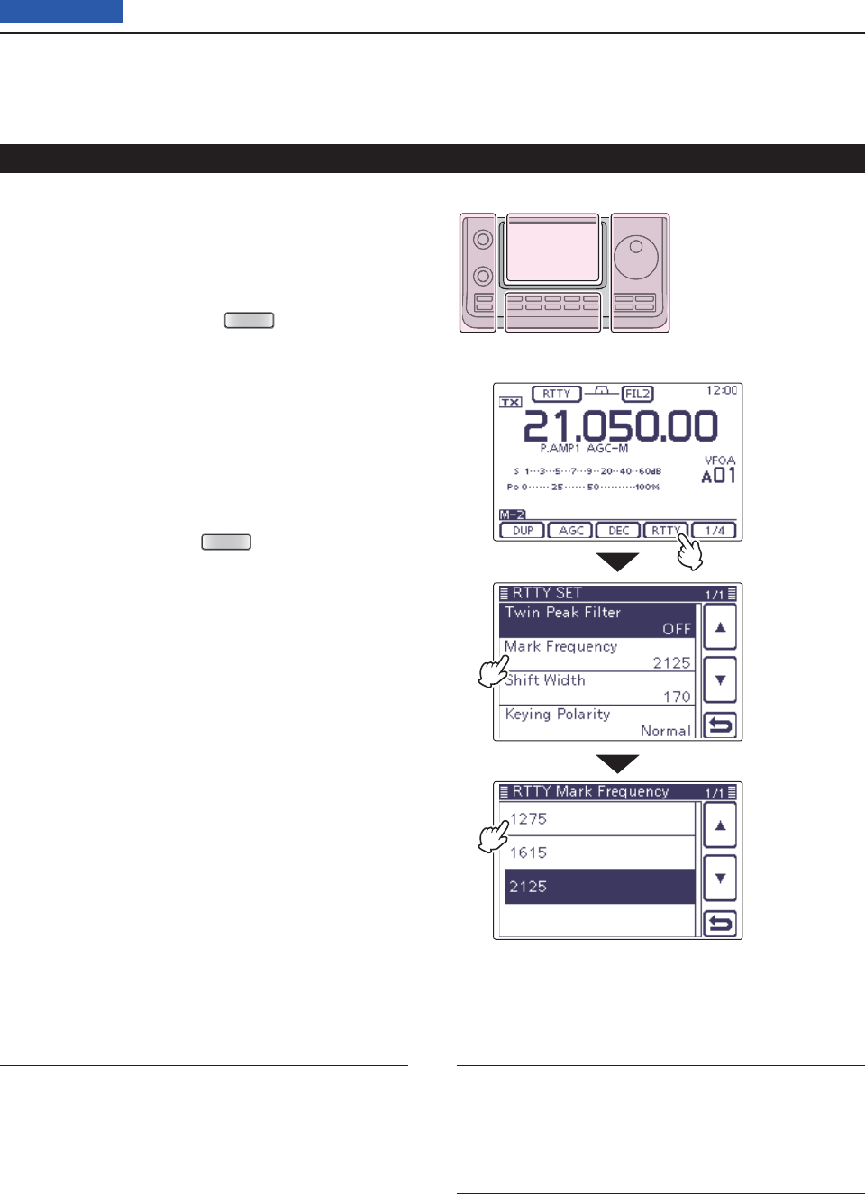
RTTY Set mode D
The RTTY Set mode is used to set the Twin peak fi lter
function, mark and shift frequencies and the keying po-
larity.
• Setting contents
In the RTTY mode, push q
MENU
(C) one or more
times to select the “M-2” screen (Menu M-2).
Touch [RTTY]( wD) to display the “RTTY SET”
screen.
Touch the desired item to select. e
• See below for details of the set items and options.
Touch the rdesired option or rotate the Dial to change
the setting.
• If desired, touch the item for 1 second to open the De-
fault set window, then select the “Default” to reset to the
default setting.
Touch [ t](D) or push
MENU
(C) to return to the
“M-2” screen (Menu M-2).
Twin Peak Filter (Default: OFF)
Turn the Twin Peak Filter ON or OFF.
Mark Frequency (Default: 2125)
Select the RTTY mark frequency.
• 1275, 1615 and 2125 Hz are selectable.
Shift Width (Default: 170)
Select the RTTY frequency shift.
• 170, 200 and 425 Hz are selectable.
Keying Polarity (Default: NORMAL)
Select normal or reverse keying polarity.
• NORMAL: Key open/close = Mark/Space
• REVERSE: Key open/close = Space/Mark
The functions for RTTY operation (Continued)
The L, R, C or D in the
instructions indicate the
part of the controller.
L: Left side
R: Right side
C: Center bottom
D: Display (Touch panel)
Left Right
Center
Display
Touch the option
(Example: 1275)
Touch the item
(Example: Mark
Frequency)
Touch [RTTY]
4RECEIVE AND TRANSMIT
4-15
Previous view
The functions for RTTY operation (Continued)
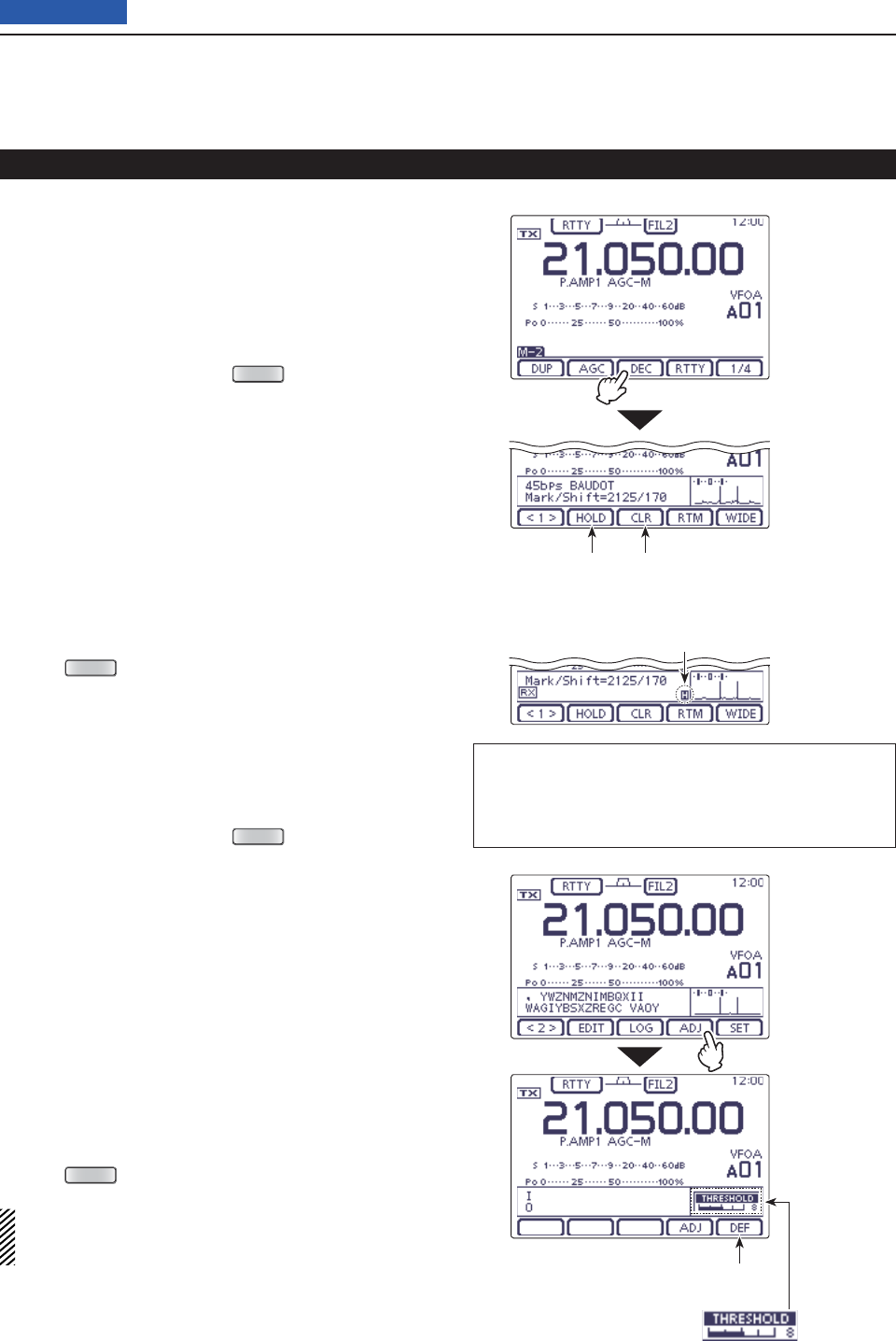
RTTY decoder D
The transceiver has an RTTY decoder for Baudot (mark
frequency: 2125 Hz, shift frequency: 170 Hz, 45 bps).
An external terminal unit (TU) or terminal node con-
nector (TNC) is not necessary for receiving a Baudot
signal.
In the RTTY mode, push q
MENU
(C) one or more
times to select the “M-2” screen (Menu M-2).
Touch [DEC]( wD) to display the RTTY decoder
screen.
• Touch [WIDE](D) to toggle the decode screen size be-
tween normal and wide.
Touch [HOLD]( eD) to turn ON the Hold function to
hold the current screen.
• “H” appears when this function is turned ON.
• Touch [HOLD](D) again to turn OFF the Hold function.
Touch [CLR]( rD) for 1 second to clear the displayed
characters.
• “H” disappears at the same time as the displayed char-
acters are cleared. (The hold function is cancelled.)
Push t
MENU
(C) to return to the “M-2” screen (Menu
M-2).
• Setting the decoder threshold level
If some characters are displayed when no signal is re-
ceived, adjust the RTTY decoder threshold level.
In the RTTY mode, push q
MENU
(C) one or more
times to select the “M-2” screen (Menu M-2).
Touch [DEC]( wD) to display the RTTY decoder
screen.
• Touch [WIDE](D) to toggle the decode screen size be-
tween normal and wide.
Touch [<1>]( eD) to display the RTTY decoder (2)
screen.
• Touch [<1>] or [<2>](D) to toggle between the RTTY de-
coder and the RTTY decode (2) screens.
Touch [ADJ]( rD) to select the threshold level adjust-
ment mode.
Rotate the Dial to adjust the RTTY decoder thresh- t
old level.
• Touch [DEF](D) for 1 second to reset to the default set-
ting, if desired.
Push y
MENU
(C) to exit the adjustment mode.
The number of the decoder display lines, the UnShift
On Space (USOS) function and new line code can
be set in the RTTY Set mode. (p. 60)
The L, R, C or D in the instructions indicate the
part of the controller.
L: Left side, R: Right side, C: Center bottom
D: Display (Touch panel)
Hold function
ON/OFF
Clear the character
Appears when the Hold function
is turned ON.
Touch [DEC]
Touch [ADJ]
Touch for 1 second to reset
the threshold level to default.
Threshold level display
4RECEIVE AND TRANSMIT
4-16
Previous view
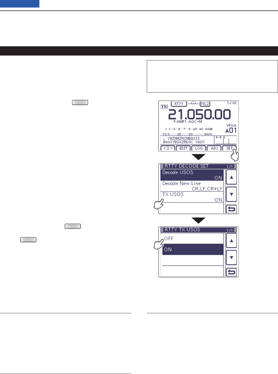
Decode USOS (Default: ON)
Turn the USOS (UnShift On Space) function ON or
OFF. This function decodes a letter code after receiving
a “space.”
• OFF: Decodes as a character code
• ON: Decodes as a letter code
Decode New Line (Default: CR,LF,CR+LF)
Select the internal RTTY decoder new line code.
CR: Carriage Return, LF: Line Feed
• CR,LF,CR+LF: Makes a new line with any code.
• CR+LF: Makes a new line with only the CR+LF
code.
TX USOS (Default: ON)
Explicitly inserts the FIGS character, even though it is
not required by the receiving station.
• OFF: Inserts FIGS
• ON: Does not insert FIGS
The functions for RTTY operation (Continued)
RTTY decode Set mode D
The RTTY decode Set mode is used to set the decode
USOS function, RTTY decoder new line code and the
TX USOS function.
• Setting contents
In the RTTY mode, push q
MENU
(C) one or more
times to select the “M-2” screen (Menu M-2).
Touch [DEC]( wD) to display the RTTY decoder
screen.
• Touch [WIDE](D) to toggle the decode screen size be-
tween normal and wide.
Touch [<1>]( eD) to display the RTTY decoder (2)
screen.
• Touch [<1>] or [<2>](D) to toggle between the RTTY de-
coder and the RTTY decode (2) screens.
Touch [SET]( rD) to enter the “RTTY DECODE SET”
screen.
Touch the desired item to select. t
• See below for details of the set items and options.
Touch the ydesired option or rotate the Dial to change
the setting.
• If desired, touch the item for 1 second to open the De-
fault set window, then select the “Default” to reset to the
default setting.
Touch [ u](D) or push
MENU
(C) to return to the
“KEYER” (Root) screen.
Push i
MENU
(C)
to return to the “M-2” screen (Menu
2)
.
The L, R, C or D in the instructions indicate the
part of the controller.
L: Left side, R: Right side, C: Center bottom
D: Display (Touch panel)
Touch [SET]
Touch the item
( Example: TX
USOS)
Touch the option
(Example: OFF)
4RECEIVE AND TRANSMIT
4-17
Previous view
The functions for RTTY operation (Continued)
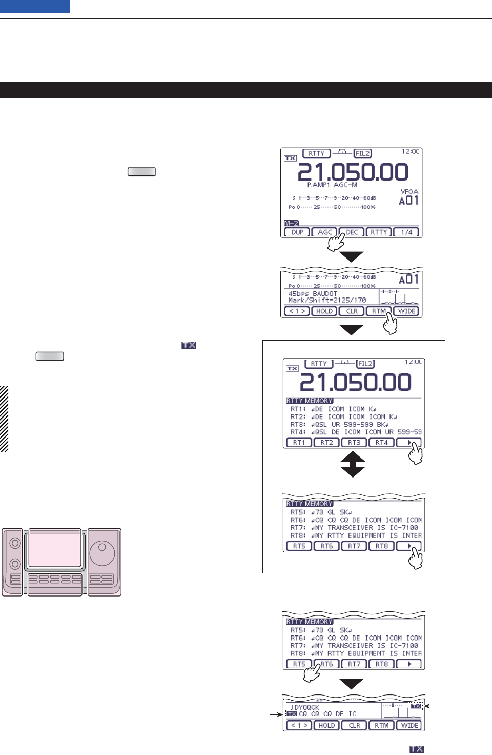
RTTY memory screen (RT1–RT4)
RTTY memory screen (RT5–RT8)
Transmitting an RTTY memory D
Previously entered characters can be sent using the
RTTY memory. Contents of the memory are enter in
the RTTY Memory (Edit) screen.
In the RTTY mode, push q
MENU
(C) one or more
times to select the “M-2” screen (Menu M-2).
Touch [DEC]( wD) to display the RTTY decoder
screen.
• Touch [WIDE](D) to toggle the decode screen size be-
tween normal and wide.
Touch [RTM]( eD) to display the RTTY memory
screen.
Touch [ r](D) to select the memory group to trans-
mit.
• Touch [](D) to toggle the memory group between RT1–
RT4 and RT5–RT8.
Touch one of the memory keys, [RT1] to [RT4], or t
[RT5] to [RT8](D).
• The TX/RX indicator lights red.
• The TX contents are displayed beside the “ ” icon.
Push y
MENU
(C) to return to the “M-2” screen (Menu
M-2).
For your information
When an external keypad is connected to [MIC] con-
nector on the Controller, one of RT1 to RT4 RTTY
memory contents can be transmitted while the RTTY
decode screen is selected in the RTTY mode. (pgs.
18, 133)
The L, R, C or D in the
instructions indicate the
part of the controller.
L: Left side
R: Right side
C: Center bottom
D: Display (Touch panel)
Left Right
Center
Display
• Transmits RT6
Touch [DEC]
Touch [RTM]
Touch [RT6]
The TX contents are displayed “ ” blinks
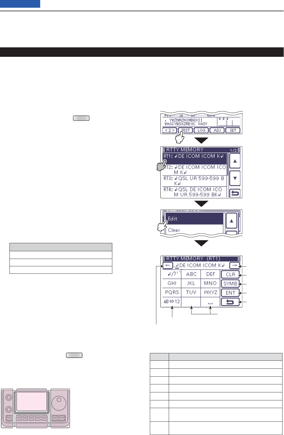
4RECEIVE AND TRANSMIT
4-18
Previous view
• Preprogrammed contents
CH Contents
RT1 DE ICOM ICOM K
RT2 DE ICOM ICOM ICOM K
RT3 QSL UR 599–599 BK
RT4 QSL DE ICOM ICOM UR 599–599 BK
RT5 73 GL SK
RT6 CQ CQ CQ DE ICOM ICOM ICOM K
RT7 MY TRANSCEIVER IS IC–7100 & ANTENNA IS A
3–ELEMENT TRIBAND YAGI.
RT8 MY RTTY EQUIPMENT IS INTERNAL FSK UNIT &
DEMODULATOR OF THE IC–7100.
Touch “Edit”
• RTTY memory programming mode
• RT1 default indication
Input a space
Select Alphabet or Number input
Move the cursor
Move the cursor
Delete a character
Select a Symbol
Enter
Cancel edit
Touch [EDIT]
Touch the desired
channel for 1 sec-
ond
Editing an RTTY memory D
The contents of the RTTY memories can be set on the
RTTY Memory (Edit) screen. The RTTY memory can
memorize and retransmit 8 RTTY message for often-
used RTTY information. The total capacity of the RTTY
memory is 70 characters per memory channel.
• Programming contents
q
In the RTTY mode,
push
MENU
(C) one or more
times to select the “M-2” screen (M-2 menu).
Touch [DEC]( wD) to display the RTTY decoder
screen.
• Touch [WIDE](D) to toggle the decode screen size be-
tween normal and wide.
Touch [<1>]( eD) to display the RTTY decoder (2)
screen.
• Touch [<1>] or [<2>](D) to toggle between the RTTY de-
coder and the RTTY decode (2) screens.
Touch [EDIT]( rD) to display the “RTTY MEMORY”
(Edit) screen.
• The memory contents are displayed.
Touch for 1 second on a desired memory channel to t
be edited, and then touch “Edit.”
• Touch [] or [](D) to select the displayed page.
• The memory programming screen appears.
Touch the desired block one or more times to select y
the desired character or symbol.
Selectable characters and symbols
ABCDEFGHIJKLMNOPQRSTUVWXYZ
1234567890
! $ & ? " ' – / . , : ; ( )
• Touch “AB12” to toggle between the Alphabet input
and Number input mode.
• Touch [CLR](D) to delete the selected character, symbol
or number.
• Touch [SYMB](D) to open the Symbol character selec-
tion window.
• Touch “” to input a space.
Touch [ u](D) or [](D) to move the cursor back-
wards or forwards.
Repeat steps iy and u to program up to 70 charac-
ters of memory contents, and then push [ENT](D).
Touch [ o](D) or push
MENU
(C) to return to the
RTTY Decode (2) screen.
The functions for RTTY operation (Continued)
The L, R, C or D in the
instructions indicate the
part of the controller.
L: Left side
R: Right side
C: Center bottom
D: Display (Touch panel)
Left Right
Center
Display
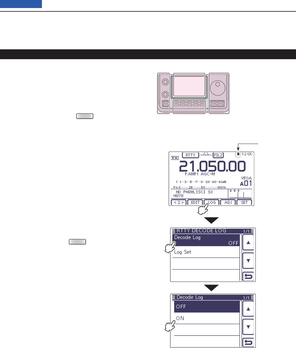
4RECEIVE AND TRANSMIT
4-19
Previous view
• RTTY decode log
SD card icon
Turning ON the RTTY decode log D
Turn ON the RTTY decode log to store your RTTY op-
erating record, both TX and RX, into an SD card.
Be sure to insert the SD card, otherwise this function
does not work properly. The SD card is not supplied
byu Icom.
q
In the RTTY mode,
push
MENU
(C) one or more
times to select the “M-2” screen (M-2 menu).
Touch [DEC]( wD) to display the RTTY decoder
screen.
• Touch [WIDE](D) to toggle the decode screen size be-
tween normal and wide.
Touch [<1>]( eD) to display the RTTY decoder (2)
screen.
• Touch [<1>] or [<2>](D) to toggle between the RTTY de-
coder and the RTTY decode (2) screens.
Touch [LOG]( rD) to display the “RTTY DECODE
LOG” screen.
Touch “Decode Log,” and then select the RTTY de- t
code log function ON or OFF.
• If desired, touch the item for 1 second to open the Default
set window, then select “Default” to reset to the default
setting.
• When “ON” is selected, the RTTY decode log starts.
Touch [ y](D) or push
MENU
(C) to return to the
RTTY Decoder screen.
The functions for RTTY operation (Continued)
The L, R, C or D in the
instructions indicate the
part of the controller.
L: Left side
R: Right side
C: Center bottom
D: Display (Touch panel)
Left Right
Center
Display
Touch [LOG]
Touch “Decode
Log”
Touch “ON”
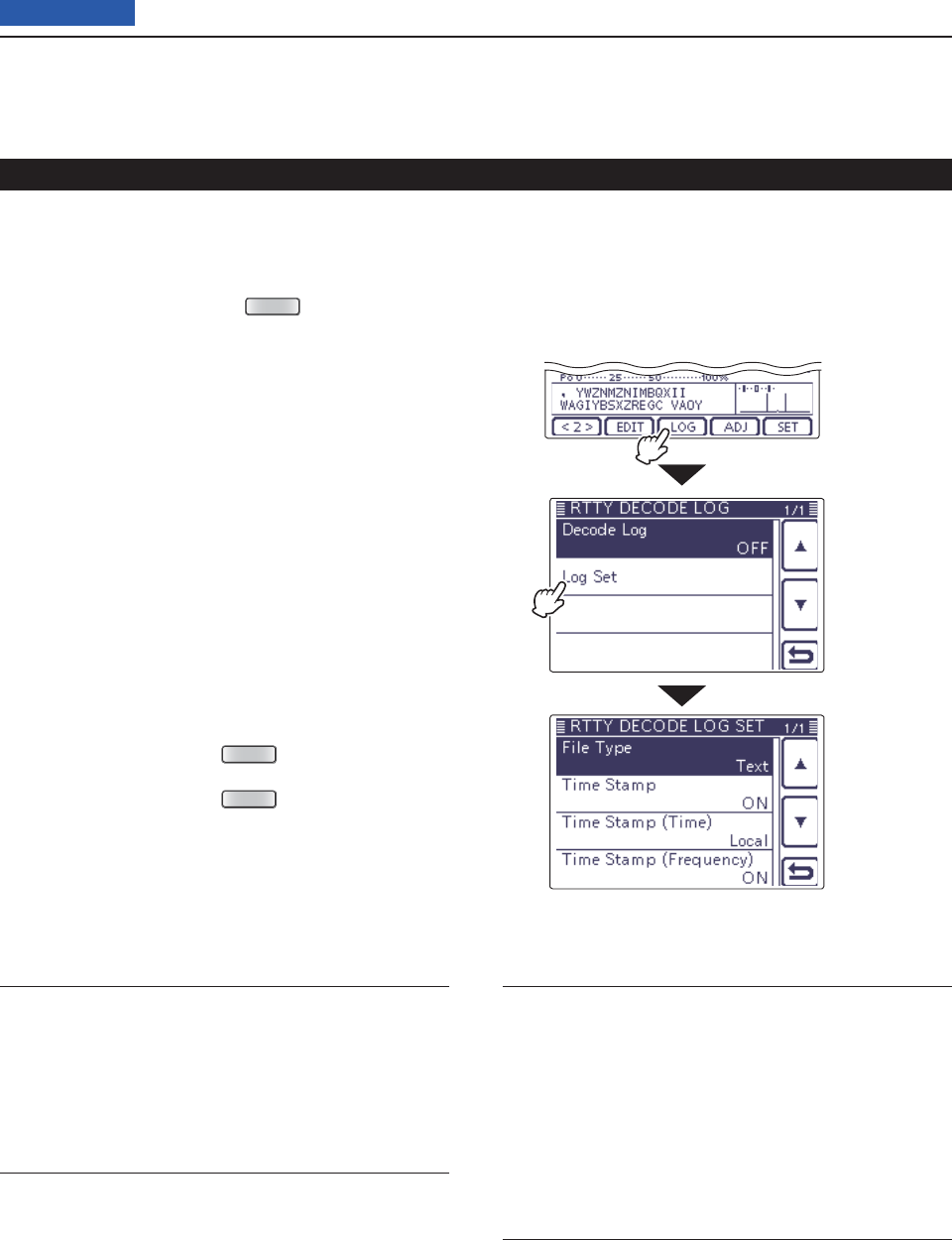
4RECEIVE AND TRANSMIT
4-20
Previous view
RTTY decode log Set mode
RTTY decode log Set mode D
The RTTY decode log Set mode is used to set the File
Type and the Time stamps.
q
In the RTTY mode,
push
MENU
(C) one or more
times to select the “M-2” screen (M-2 menu).
Touch [DEC]( wD) to display the RTTY decoder
screen.
• Touch [WIDE](D) to toggle the decode screen size be-
tween normal and wide.
Touch [<1>]( eD) to display the RTTY decoder (2)
screen.
• Touch [<1>] or [<2>](D) to toggle between the RTTY de-
coder and the RTTY decode (2) screens.
Touch [LOG]( rD) to display the “RTTY DECODE
LOG” screen.
Touch “Log Set” to enter the “RTTY DECODE LOG t
SET” screen.
Touch the desired item to select. y
• See below for details of the set items and options.
Touch the udesired option to change the setting.
• If desired, touch the item for 1 second to open the De-
fault set window, then select the “Default” to reset to the
default setting.
Touch [ i](D) or push
MENU
(C) to return to the
“RTTY DECODE LOG” screen.
Touch [ o](D) or push
MENU
(C) to return to the
RTTY Decoder screen.
The functions for RTTY operation (Continued)
File type (Default: Text)
Select fi le type for saving a Log into an SD card, as the
Text or HTML format.
• Text: Save as a Text format
• HTML: Save as an HTML format
Time stamp (Default: ON)
Adds the time stamp (date, transmission or reception
time) to the LOG fi le.
• OFF: Does not save the time stamp.
• ON: Saves the date and time data.
Time stamp (time) (Default: Local)
Select the time of the time stamp whether it is in local
or UTC.
NOTE: The time won’t be saved when “OFF” is selected
in “Time Stamp” to the left.
• Local: The time is used in Local time
• UTC: The time is used in UTC time
Time stamp (frequency) (Default: ON)
Selects the time stamp data whether adding the fre-
quency or not.
NOTE: The frequency won’t be saved when “OFF” is
selected in “Time Stamp” to the left.
• OFF: Does not save the frequency
• ON: Saves the frequency data
Touch [LOG]
Touch “Log Set”
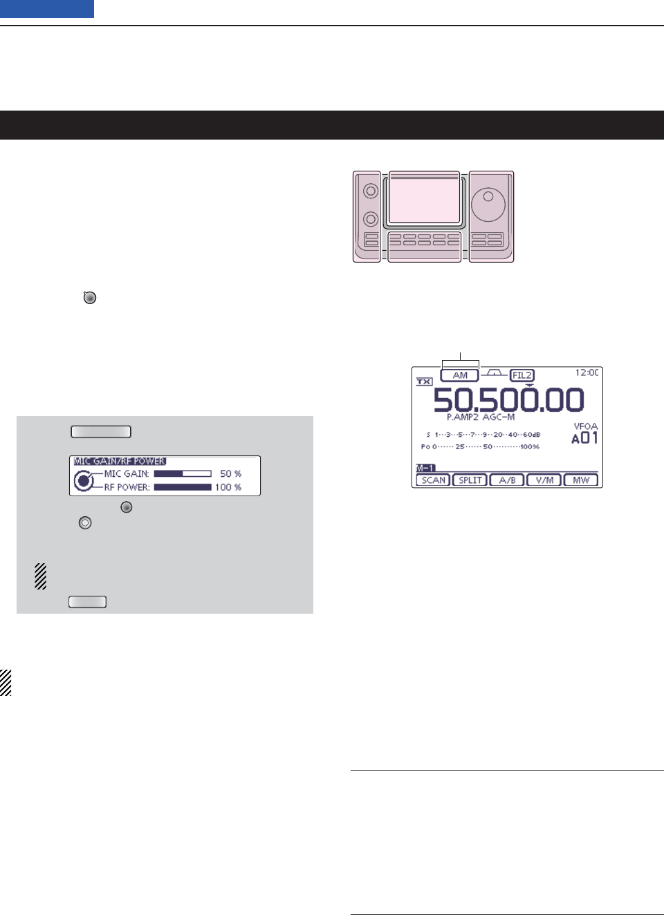
4RECEIVE AND TRANSMIT
4-21
Previous view
Select the desired frequency band. (p. 35) q
On the Mode selection screen, touch “AM” or “FM” to w
select the AM or FM mode.
• To select the data mode, after selecting AM or FM, touch
“DATA” to select the data mode, if needed.
Rotate the Dial to tune a desired signal. e
• The S-meter displays the received signal strength.
•
The tuning step can be changed on the Tuning step selec-
tion screen by touching “kHz frequency.” (p. 38)
Rotate [AF] r(L)to adjust the audio to a comfort-
able listening level.
Push [PTT] on the microphone to transmit. t
• The TX/RX indicator lights red.
Speak into the microphone at your normal voice y
level.
If necessary, adjust the microphone gain or RF pow- u
er on the Mic gain/RF power adjustment display.
q Push
MIC/RF PWR
(C) to open the MIC gain/RF
power adjustment display.
w Rotate [M-CH] (L) to adjust the MIC gain, or
[BANK] (L) to adjust the RF power.
• To adjust the MIC gain, adjust it with another station
listening to your voice for clarity.
When the MIC gain is adjusted too high, your
transmitted voice may be distorted.
e Push
MENU
(C) to close the display.
Release [PTT] to receive. i
NOTE: On the 144/440 MHz frequency band, you
can transmit in the AM mode.
Operating AM/FM
Convenient Receive functions
• Preamp and attenuator (p. 71)
• Twin PBT (passband tuning) (p. 75)
This function is not usable in the FM mode.
• AGC (auto gain control) (p. 72)
• Noise blanker (p. 76)
• Noise reduction (p. 77)
• Notch fi lter (p. 77)
Convenient Transmit functions
• VOX (voice operated transmit) (p. 80)
• Transmit quality monitor (p. 81)
• Tone control (p. 169)
The L, R, C or D in the
instructions indicate the
part of the controller.
L: Left side
R: Right side
C: Center bottom
D: Display (Touch panel)
Left Right
Center
Display
“AM” or “FM” appears
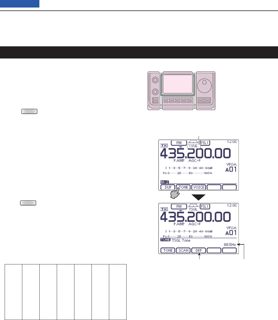
4RECEIVE AND TRANSMIT
4-22
Previous view
The tone squelch opens only when you receive a signal
containing a matching subaudible tone. You can silently
wait for calls from others using the same tone.
Select the desired frequency band. (p. 35) q
On the Mode selection screen, touch “FM” to select w
the FM mode.
Push e
MENU
(C) one or more times to select the
“M-2” screen (M-2 menu).
Touch [TONE]( rD) one or more times to turn ON the
Tone squelch function.
• “TSQL” appears.
• Touch [TONE](D) to toggle between “TONE,” “TSQL,”
“DTCS” and OFF (icon disappears).
Touch [TONE]( tD) for 1 second to display the “TONE”
screen.
• “TSQL Tone” appears.
Rotate the Dial to select the desired tone squelch y
frequency. See the table shown below.
• If desired, touch [DEF] for 1 second to reset to the default
setting.
Push u
MENU
(C) to exit the “TONE” screen.
Communicate in the usual manner. i
• The tone squelch opens only when you receive a signal
containing a matching subaudible tone.
• Subaudible tones are superimposed on your transmit sig-
nal.
Tone squelch operation
67.0 88.5 114.8 151.4 177.3 203.5 250.3
69.3 91.5 118.8 156.7 179.9 206.5 254.1
71.9 94.8 123.0 159.8 183.5 210.7
74.4 97.4 127.3 162.2 186.2 218.1
77.0 100.0 131.8 165.5 189.9 225.7
79.7 103.5 136.5 167.9 192.8 229.1
82.5 107.2 141.3 171.3 196.6 233.6
85.4 110.9 146.2 173.8 199.5 241.8
The L, R, C or D in the
instructions indicate the
part of the controller.
L: Left side
R: Right side
C: Center bottom
D: Display (Touch panel)
Left Right
Center
Display
• Available tone squelch frequencies (Unit: Hz)
Touch [TONE]
for 1 second
TSQL icon
Touch for 1 second
to reset to default
Tone frequency
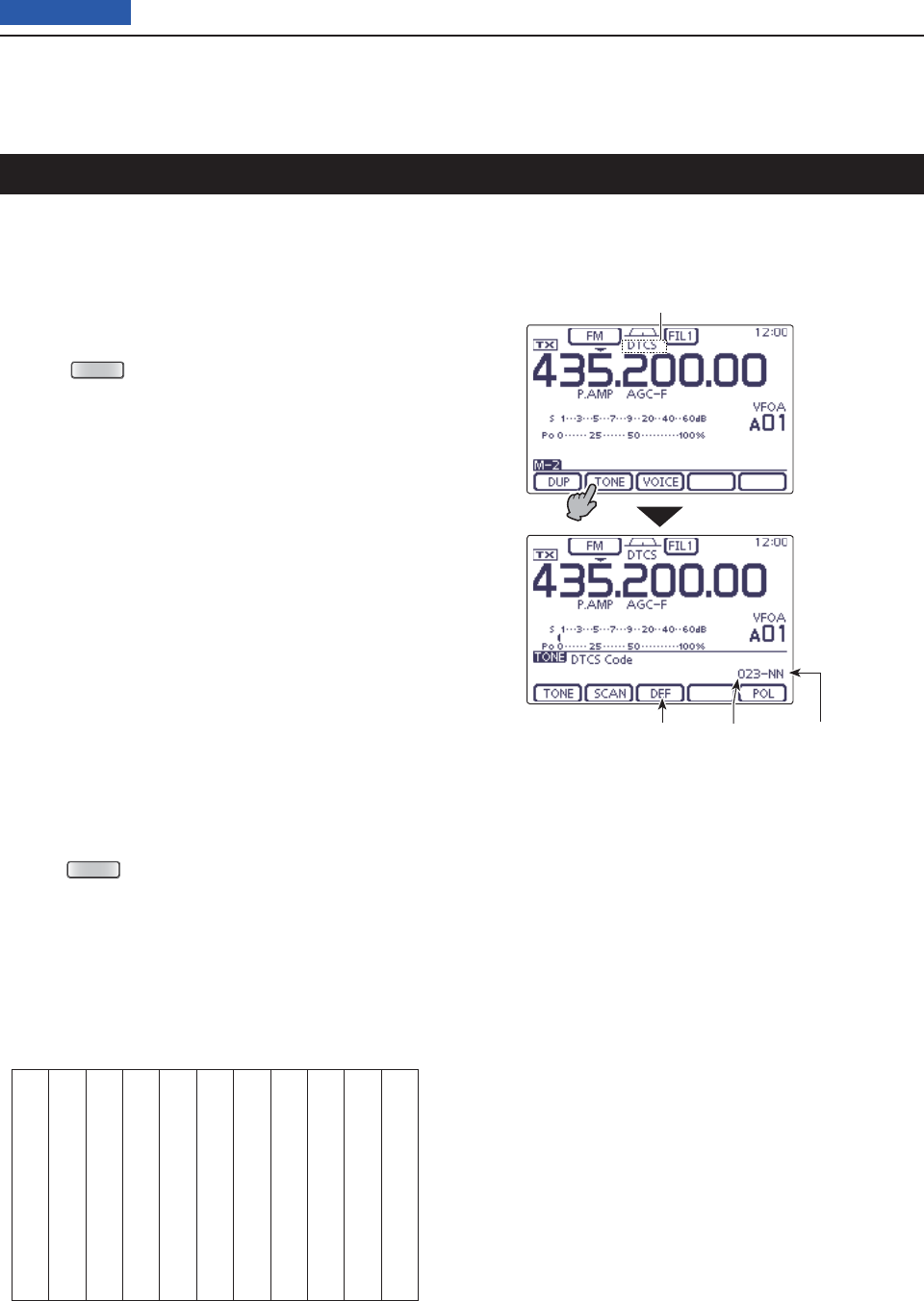
4RECEIVE AND TRANSMIT
4-23
Previous view
The DTCS function is another method of communica-
tions using selective calling. Only received signals hav-
ing a matching 3-digit code will open the squelch.
Select the desired frequency band. (p. 35) q
On the Mode selection screen, touch “FM” to select w
the FM mode.
Push e
MENU
(C) one or more times to select the
“M-2” screen (M-2 menu).
Touch [TONE]( rD) one or more times to turn ON the
DTCS function.
• “DTCS” appears.
• Touch [TONE](D) to toggle between “TONE,” “TSQL,”
“DTCS” and OFF (icon disappears).
Touch [TONE]( tD) for 1 second to display the “TONE”
screen.
• “DTCS Code” appears.
Rotate the Dial to select the desired DTCS code y
number. And touch [POL](D) to select the desired
code polarity.
NN: Normal polarity is used for both transmit and
receive. (Default)
NR: Normal polarity is used for transmit, reversed
polarity is used for receive.
RN: Reversed polarity is used for transmit, normal
polarity is used for receive.
RR: Reversed polarity is used for both transmit and
receive.
• If desired, touch [DEF] for 1 second to reset to the default
setting.
Push u
MENU
(C) to exit the “TONE” screen.
Communicate in the usual manner. i
• The tone squelch opens only when you receive a signal
containing a matching subaudible tone.
• Subaudible tones are superimposed on your transmit sig-
nal.
DTCS operation
• Available DTCS codes
023 054 125 165 245 274 356 445 506 627 732
025 065 131 172 246 306 364 446 516 631 734
026 071 132 174 251 311 365 452 523 632 743
031 072 134 205 252 315 371 454 526 654 754
032 073 143 212 255 325 411 455 532 662
036 074 145 223 261 331 412 462 546 664
043 114 152 225 263 332 413 464 565 703
047 115 155 226 265 343 423 465 606 712
051 116 156 243 266 346 431 466 612 723
053 122 162 244 271 351 432 503 624 731
Touch [TONE]
for 1 second
DTCS icon
Touch for 1 second
to reset to default
DTCS code DTCS polarity
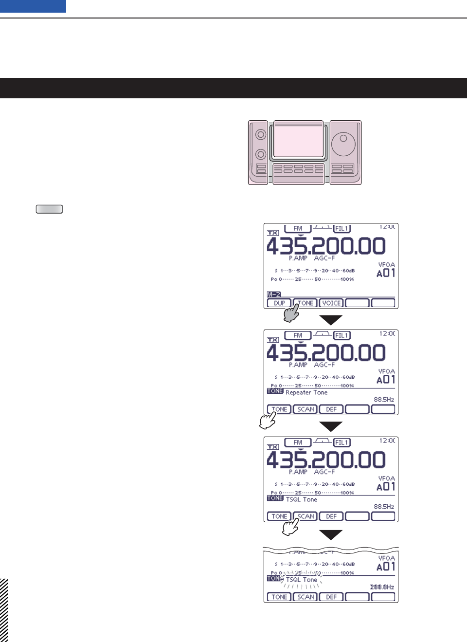
4RECEIVE AND TRANSMIT
4-24
Previous view
To search for a repeater’s sub-audible tone frequency,
a tone scan is available.
By monitoring a repeater signal with a tone squelch or
DTCS, you can determine the tone frequency neces-
sary to open the repeater or the squelch.
Select the desired frequency band. (p. 35) q
On the Mode selection screen, touch “FM” to select w
the FM mode.
Push e
MENU
(C) one or more times to select the
“M-2” screen (M-2 menu).
Touch [TONE]( rD) for 1 second to display the “TONE”
screen.
Touch [TONE]( tD) one or more times to select the
tone type to be scanned.
• “Repeater Tone” for a repeater tone, “TSQL Tone” for tone
squelch or “DTCS Code” for a DTCS code, appears.
• When selecting a DTCS code to be scanned, the DTCS
code and its polarity is displayed. You can select the de-
sired polarity by pushing [POL](D).
“NN”: Normal polarity for both transmit and receive.
“NR”: Normal polarity for transmit and reverse polarity for
receive.
“RN”: Reverse polarity for transmit and normal polarity for
receive.
“RR”: Reverse polarity for both transmit and receive.
Touch [SCAN]( yD) to start the Tone or DTCS scan.
• “Repeater Tone SCAN,” “TSQL Tone SCAN” or “DTCS
Code SCAN” blinks, depending on the type you select-
ed.
• If the squelch is open while scanning, the scan speed
decreases.
• If
“Up/Down” is selected as
the “MAIN DIAL (SCAN)” op-
tion
in the Scan Set mode, rotating the Dial changes the
scanning direction. (p. 147)
When a matched tone or code is found, the scan u
pauses, and the detected subaudible tone frequency
or DTCS code is set.
• If desired, touch [DEF] for 1 second to reset to the default
setting.
Touch [SCAN]( iD) to cancel the scan.
When the tone scan or DTCS code scan is used in
the Memory or Call channel mode, the detected tone
frequency or code can be temporarily used.
To save the detected tone frequency or code setting,
you must overwrite the Memory or Call channel data.
(pp. 140, 141)
Tone scan/DTCS code scan operation
The L, R, C or D in the
instructions indicate the
part of the controller.
L: Left side
R: Right side
C: Center bottom
D: Display (Touch panel)
Left Right
Center
Display
While Tone scanning in the VFO mode
Touch [TONE] to
select the tone
type
Touch [TONE]
for 1 second
Touch [SCAN]
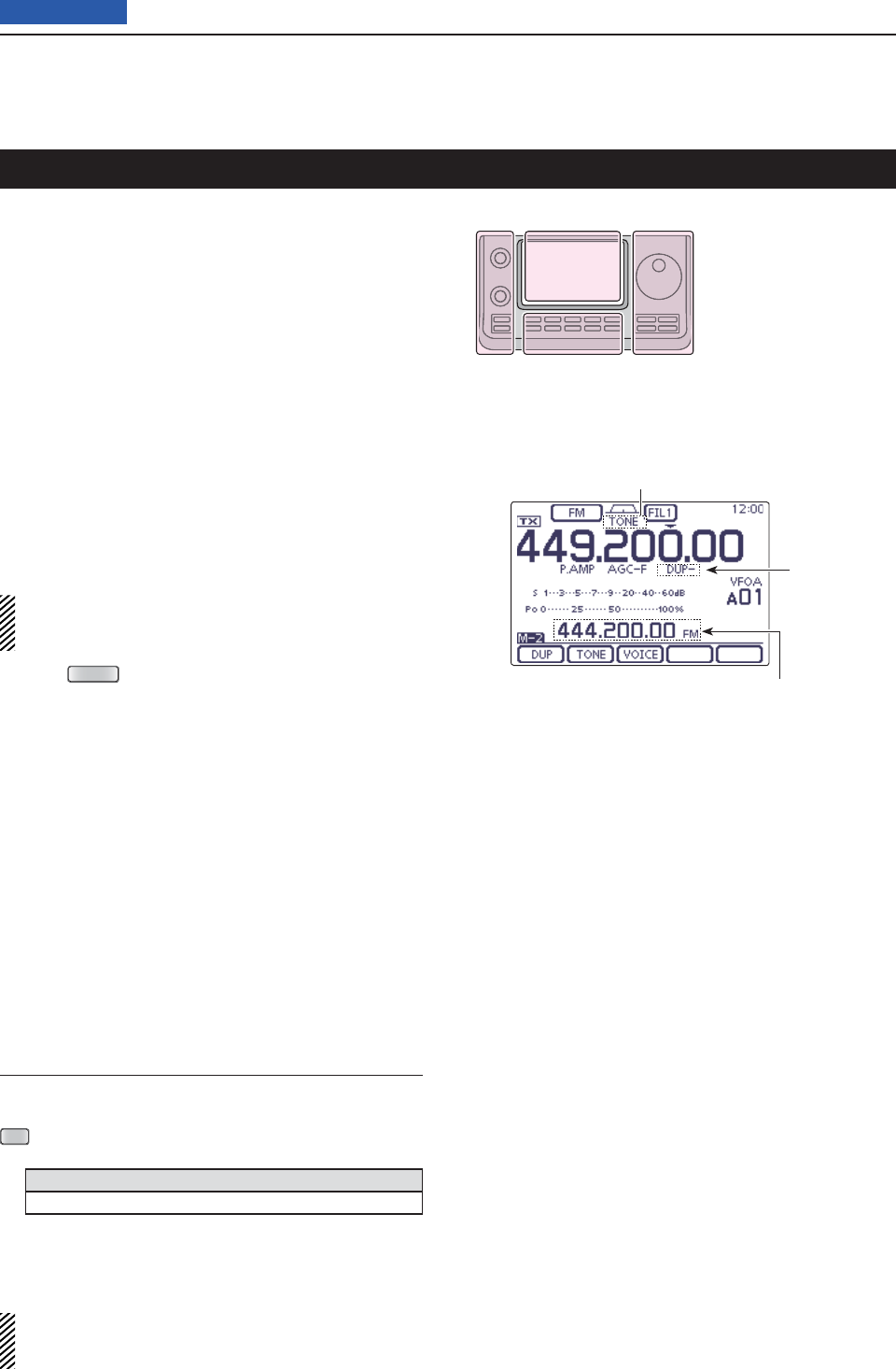
4RECEIVE AND TRANSMIT
4-25
Previous view
A repeater receives transmitted signals and retransmits
them on a different frequency. When using a repeater,
the transmit frequency is shifted from the receive fre-
quency by a frequency offset.
A repeater can be accessed using the duplex function-
by setting the frequency shift to the same value as the
repeater’s frequency offset.
See page 94 for details on accessing a D-STAR®
repeater.
Touch the Memory channel indication once or twice q
to select the VFO mode.
Select the desired frequency band. (p. 35) w
On the Mode selection screen, touch “FM” to select e
the FM mode.
Rotate the Dial to set the receive frequency (Repeat- r
er output frequency).
When the Auto Repeater function is turned ON
(available in only the U.S.A. and Korea versions),
steps t and y are not necessary. (p. 67)
t
P
ush
MENU
(C) one or more times to display the
“M-2” screen (M-2 menu), then touch [DUP](D) one
or more times to set the offset direction.
• “DUP–” or “DUP+” appears.
• The transmit frequency (repeater input frequency) ap-
pears above the function menu.
• The frequency offset (amount of shift) can be set in
the
“DUP Offset” item
of the Function Set. (p. 163)
Touch [TONE]( yD) to turn ON the repeater tone.
• “TONE” appears.
• The tone frequency can be set in
the
“TONE” screen.
88.5 Hz is set by default. (p. 4-25)
Communicate in the normal way. u
• Subaudible tones are superimposed on your transmit sig-
nal.
Repeater operation
The L, R, C or D in the
instructions indicate the
part of the controller.
L: Left side
R: Right side
C: Center bottom
D: Display (Touch panel)
Left Right
Center
Display
Frequency Offset setting
The frequency offset (amount of shift) can be set in
the
“DUP Offset” item
of the Function Set. (p. 163)
SET
(C) > Function > SPLIT/DUP > DUP Offset
Frequency offset
5.0000 MHz
If the Repeater tone frequency or the frequency off-
set is changed, the tone frequency or frequency off-
set for auto repeater function is also changed.
Repeater tone icon
Transmit frequency
(Repeater input frequency)
Duplex icon
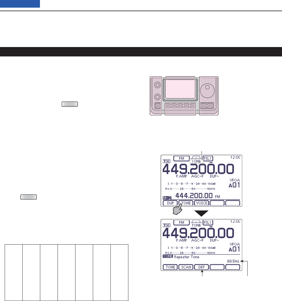
4RECEIVE AND TRANSMIT
4-26
Previous view
Repeater operation (Continued)
Repeater access tone frequency setting D
Some repeaters require a subaudible tone to be ac-
cessed. Subaudible tones are superimposed on your
normal signal and must be set fi rst. You can select 50
tones from 67.0 Hz to 254.1 Hz.
In the FM mode, push q
MENU
(C) one or more times
to select the “M-2” screen (M-2 menu).
Touch [TONE]( wD) one or more times to turn ON the
Tone encoder function.
• “TONE” appears.
• Touch [TONE](D) to toggle between “TONE,” “TSQL,”
“DTCS” and OFF (icon disappears).
Touch [TONE]( eD) for 1 second to display the “TONE”
screen.
• “Repeater Tone” appears.
Rotate the Dial to select the desired tone squelch r
frequency. See the table below.
• If desired, touch [DEF] for 1 second to reset to the default
setting.
Push t
MENU
(C) to exit the “TONE” screen.
Communicate in the normal way. y
• Subaudible tones are superimposed on your transmit sig-
nal.
67.0 88.5 114.8 151.4 177.3 203.5 250.3
69.3 91.5 118.8 156.7 179.9 206.5 254.1
71.9 94.8 123.0 159.8 183.5 210.7
74.4 97.4 127.3 162.2 186.2 218.1
77.0 100.0 131.8 165.5 189.9 225.7
79.7 103.5 136.5 167.9 192.8 229.1
82.5 107.2 141.3 171.3 196.6 233.6
85.4 110.9 146.2 173.8 199.5 241.8
• Selectable tone frequencies (Unit: Hz)
The L, R, C or D in the
instructions indicate the
part of the controller.
L: Left side
R: Right side
C: Center bottom
D: Display (Touch panel)
Left Right
Center
Display
Touch [TONE]
for 1 second
Repeater tone icon
Touch for 1 second
to reset to default
Tone frequency
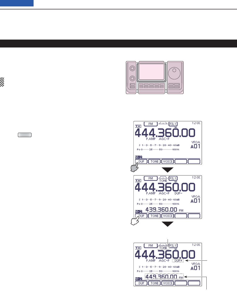
4RECEIVE AND TRANSMIT
4-27
Previous view
Repeater operation (Continued)
One-touch repeater function D
This function allows you to set the repeater operation
by holding down one switch.
First, set the frequency offset as well as the repeater
access tone frequency (p. 163).
Touch the Memory channel indication once or twice q
to select the VFO mode.
Select the desired frequency band. (p. 35) w
On the Mode selection screen, touch “FM” to select e
the FM mode.
Rotate the Dial to set the receive frequency (Repeat- r
er output frequency).
t
P
ush
MENU
(C) one or more times to display the
“M-2” screen (M-2 menu), then touch [DUP](D) for 1
second to turn ON the one touch repeater function.
• “TONE” and “DUP–” appear.
• The repeater receive frequency appears above the func-
tion menu.
• The Split Frequency mode is automatically turned OFF, if
it is ON.
Touch [DUP]( yD) one or more times to switch the off-
set direction.
• “DUP–” or “DUP+” appears.
Communicate in the normal way. u
• Subaudible tones are superimposed on your transmit sig-
nal.
The L, R, C or D in the
instructions indicate the
part of the controller.
L: Left side
R: Right side
C: Center bottom
D: Display (Touch panel)
Left Right
Center
Display
Repeater tone icon
Transmit frequency
(Repeater input frequency)
Duplex icon
Touch [DUP] for
1 second
Touch [DUP]
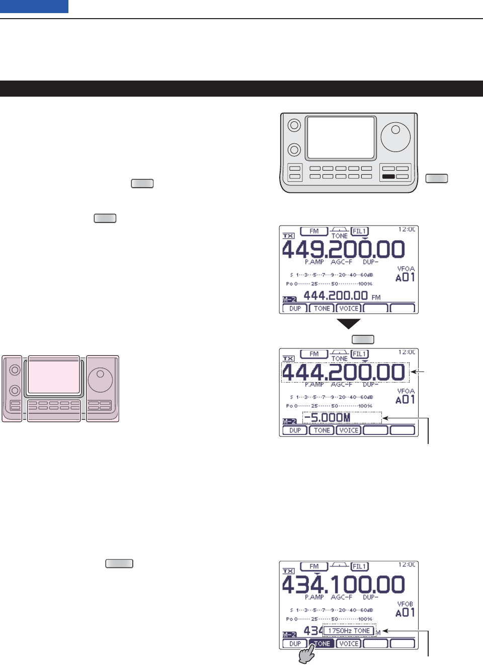
4RECEIVE AND TRANSMIT
4-28
Previous view
Repeater operation (Continued)
Transmit frequency monitor check D
You may be able to directly receive the other party’s
transmitted signal without having to go through a re-
peater. This function helps you to check whether direct
communication can be made, or not.
While receiving, hold down ➥
XFC
(R) to see if you
can directly receive the other party’s transmitted sig-
nal.
• While holding down
XFC
(R), the duplex direction and
frequency offset are displayed above the function menu.
1750 Hz tone burst D
A 1750 Hz tone is required to access most European
repeaters.
In the FM mode, q
p
ush
MENU
(C) one or more times
to select the “M-2” screen (M-2 menu).
Push [PTT] on the microphone to transmit, and then w
touch [TONE](D) during repeater access.
• “1750Hz TONE” appers.
Communicate in the normal way. e
The L, R, C or D in the
instructions indicate the
part of the controller.
L: Left side
R: Right side
C: Center bottom
D: Display (Touch panel)
Left Right
Center
Display
Hold down
XFC
XFC
Duplex direction and frequency offset
Popup window appears
Displays the
transmit fre-
quency
• While hold down
• While hold down [PTT]
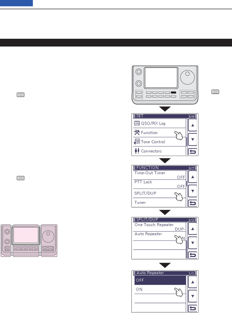
4RECEIVE AND TRANSMIT
4-29
Previous view
Repeater operation (Continued)
D Turning ON the Auto Repeater function
(U.S.A. and Korea versions only)
When the operating frequency falls within the repeater
output frequency range, the Auto Repeater function au-
tomatically sets the repeater settings (duplex ON/OFF,
duplex direction, tone encoder ON/OFF).
Push q
SET
(C) to enter the Set mode.
Touch the “Auto Repeater” item of the “Function” Set w
mode.
Function > SPLIT/DUP > Auto Repeater
• If the specifi ed item is not displayed, touch [Y] or [Z](D)
one or more times to select the page.
Touch the desired option to turn ON the Auto Re- e
peater function.
U.S.A. version:
• “ON–1” Activates duplex only.
• “ON–2” Activates duplex and tone.
• “OFF” Auto repeater function is turned OFF.
Korea version:
• “ON” Activates duplex and tone.
• “OFF” Auto repeater function is turned OFF.
Push r
SET
(C) to exit the Set mode.
The L, R, C or D in the
instructions indicate the
part of the controller.
L: Left side
R: Right side
C: Center bottom
D: Display (Touch panel)
Left Right
Center
Display
Push
SET
Touch “Function”
Touch
“SPLIT/DUP”
Touch “Auto Re-
peater”
Touch the option
Example: ON
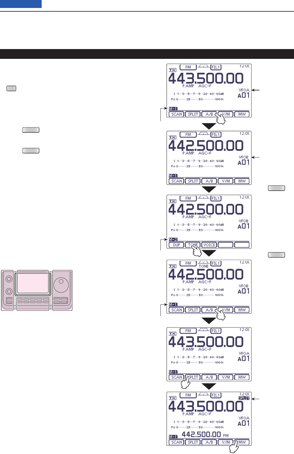
4RECEIVE AND TRANSMIT
4-30
Previous view
Storing a non standard repeater D
Turn OFF the Auto Repeater function in the “Func- q
tion” Set mode. (p. 4-28)
SET
(C) > Function > SPLIT/DUP > Auto Repeater
While the “M-1” menu is selected, touch [A/B]( wD) to
select VFO A.
Rotate the Dial to set the repeater output frequency. e
Touch [A/B]( rD) to select VFO B.
Rotate the Dial to set the repeater input frequency. t
y
P
ush
MENU
(C) to display the “M-2” screen (M-2
menu), then touch [TONE](D) to turn ON the previ-
ously set tone encoder.
u
P
ush
MENU
(C) to display the “M-1” screen (M-1
menu), then touch [A/B](D) to select VFO A.
Touch [SPLIT]( iD) to turn ON the Split function.
Rotate [M-CH]( oL) to select the desired memory
channel.
• “BLANK” appears when a blank channel is selected.
• Rotate [BANK](L) to select the desired bank, if needed.
!0 Touch [MW](D) for 1 second to store the set con-
tents into the selected memory channel.
Repeater operation (Continued)
The L, R, C or D in the
instructions indicate the
part of the controller.
L: Left side
R: Right side
C: Center bottom
D: Display (Touch panel)
Left Right
Center
Display
Touch [A/B]
Touch [TONE]
Push
MENU
(C)
Push
MENU
(C)
VFO A
Split icon
VFO B
“M-1” menu
“M-1” menu
“M-2” menu
Touch [A/B]
Touch [SPLIT]
Touch [MW] for
1 second

4RECEIVE AND TRANSMIT
4-32
Previous view
About the 5 MHz frequency band operation (USA version only) D
Operation on the 5 MHz frequency band is allowed on
5 discrete frequencies and must adhere to the follow-
ing:
• The USB, USB Data, CW and PSK modes
• Maximum of 100 watts ERP (Effective Radiated Power)
• 2.8 kHz bandwidth (maximum)
It is your responsibility to set all controls so that trans-
mission in this frequency band meets the stringent con-
ditions under which amateur operations may use these
frequencies.
NOTE: We recommend that you store these frequen-
cies, modes and fi lter settings into memory chan-
nels, for easy recall.
To assist you in operating within the rules specifi ed by the
FCC, transmission is illegal on any frequencies other than
the fi ve shown in the tables at the right.
• For the USB mode
The FCC specifi es center frequencies on the 5 MHz fre-
quency band. However, the transceiver displays carrier
frequency. Therefore, tune the transceiver to 1.5 kHz
below the specifi ed FCC channel center frequency.
Transceiver Displayed
Frequency
FCC Channel
Center Frequency
5.33050 MHz 5.33200 MHz
5.34650 MHz 5.34800 MHz
5.35700 MHz 5.35850 MHz
5.37150 MHz 5.37300 MHz
5.40350 MHz 5.40500 MHz
• For the CW mode
The transceiver displays the center frequency. There-
fore, tune the transceiver to the specifi ed FCC channel
frequency when you operate in the CW mode.
Transceiver Displayed
Frequency
FCC Channel
Center Frequency
5.33200 MHz 5.33200 MHz
5.34800 MHz 5.34800 MHz
5.35850 MHz 5.35850 MHz
5.37300 MHz 5.37300 MHz
5.40500 MHz 5.40500 MHz

Preamp and attenuator ...........................................................5-2
Preamplifi er D .............................................................................5-2
Attenuator D ................................................................................5-2
AGC function ............................................................................5-3
AGC speed selection D ...............................................................5-3
Setting the AGC time constant D ................................................5-3
RIT function ..............................................................................5-4
Twin PBT operation .................................................................5-5
IF fi lter selection ......................................................................5-6
IF fi lter selection D ......................................................................5-6
Filter passband width setting D ................................................... 5-6
IF (DSP) fi lter shape ................................................................5-7
Noise Blanker ...........................................................................5-8
NB Set mode D ...........................................................................5-8
Noise Reduction ......................................................................5-9
Notch function .........................................................................5-10
Auto Notch function D .................................................................5-10
Manual Notch function D .............................................................5-11
Lock function ...........................................................................5-12
Selecting the Lock type D ...........................................................5-12
Meter peak hold function ........................................................5-13
Simple Band Scope .................................................................5-14
5-1
Section 5FUNCTIONS FOR RECEIVE
Previous view
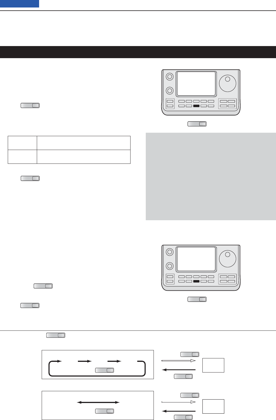
5FUNCTIONS FOR RECEIVE
5-2
Previous view
Preamplifi er D
The preamplifi er amplifi es weak signals in the receiver
front end, to improve the S/N ratio and sensitivity.
Turn ON this function when receiving weak signals.
(Frequency band: HF/50 MHz)
➥ Push
P.AMP
ATT
(C) one or more times to set the pre-
amp OFF, preamp 1 ON or preamp 2 ON.
• Either “P.AMP1” or “P.AMP2” is displayed when the pre-
amp 1 or preamp 2 is ON.
• No icon is displayed when the preamplifi er is OFF.
P.AMP1 Wide dynamic range preamplifi er. It is most
effective for the 1.8 to 21 MHz bands.
P.AMP2 High-gain preamplifi er. It is most effective
for the 24 to 50 MHz bands.
(Frequency band: 144/430 MHz)
➥ Push
P.AMP
ATT
(C) turn the Preamplifi er ON or OFF.
• “P.AMP” appears when the preamplifi er is ON.
• No icon is displayed when it’s OFF.
Attenuator D
The attenuator prevents a desired signal from being
distorted when very strong signals are near the signal’s
frequency, or when very strong electromagnetic fi elds,
such as from broadcast stations are near your location.
These can both be independently set for each band.
➥
Hold down
P.AMP
ATT
(C)
for 1 second to turn ON the
Attenuator.
• “ATT” appears on the display when the Attenuator is ON.
➥ Push
P.AMP
ATT
(C) to turn it OFF.
✔ About the “P.AMP2” preamplifi er
Preamp 2 is a high gain receive amplifi er. When it is
used in the presence of strong electromagnetic fi elds,
distortion sometimes results. In such cases, use ei-
ther the “P.AMP1” or “P.AMP OFF” setting.
Preamp 2 is most effective when:
• Used on bands above 24 MHz and when signals are
weak.
• Receive sensitivity is insuffi cient when using low-
gain antennas, or while using a narrow band an-
tenna (such as small loop, a Beverage antenna or a
short Yagi antenna).
About the Preamplifi er and Attenuator switching procedure
Push or hold down
P.AMP
ATT
(C) to switch the Preamplifi er and Attenuator, as shown below.
Hold down
Push
ATT ON
Push
P.AMP
OFF
P.AMP
ON
Push
ATT ON
P.AMP
OFF
P.AMP1
ON
P.AMP2
ON
P.AMP
ATT
P.AMP
ATT
P.AMP
ATT
Hold down
P.AMP
ATT
P.AMP
ATT
Push
P.AMP
ATT
• HF/50 MHz frequency bands
• 144/430 MHz frequency bands
Preamp and attenuator
P.AMP
ATT
P.AMP
ATT
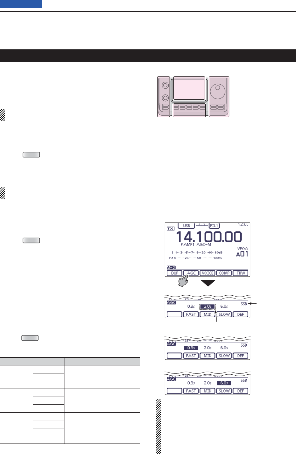
5FUNCTIONS FOR RECEIVE
5-3
Previous view
The AGC (Auto Gain Control) controls receiver gain to
produce a constant audio output level, even when the
received signal strength greatly varies.
The transceiver has 3 pre-set AGC time constants: fast,
mid and slow for SSB, CW, RTTY and AM modes.
In the FM , WFM and DV modes, the AGC time con-
stant is fi xed as “FAST” (0.1 second).
AGC speed selection D
On the Mode selection screen, select either the SSB, q
CW, RTTY or AM mode. (p.3-??)
Push w
MENU
(C) one or more times to select the
“M-2” screen (M-2 menu).
Touch [AGC]( eD)
to select AGC-F (FAST), AGC-M
(MID) or AGC-S (SLOW).
“AGC OFF” appears when the selected AGC speed’s
time constant is set to OFF.
Setting the AGC time constant D
On the Mode selection screen, select either the SSB, q
CW, RTTY or AM mode. (p.3-??)
Push w
MENU
(C) one or more times to select the
“M-2” screen (M-2 menu).
Touch [AGC]( eD) for 1 second
to
display the “AGC”
screen.
Touch either [FAST] r, [MID] or [SLOW](D) to select
the desired AGC speed to be set.
• The selected AGC speed’s time constant is highlighted.
Rotate the Dial to set the selected time constant. t
• AGC time constant can be set to between 0.1 to 8.0 sec-
onds, (depending on the mode) or turned OFF.
• If desired, touch [DEF](D) for 1 second to reset to the
default setting for the selected time constant.
If desired, select another mode (any other than FM, y
WFM or DV), then repeat steps e and r.
Push u
MENU
(C) to exit the “AGC” screen.
• Selectable AGC time constant (unit: seconds)
Mode Default
Selectable AGC time constant
SSB
0.3 (FAST)
OFF, 0.1, 0.2, 0.3, 0.5, 0.8, 1.2,
1.6
, 2.0, 2.5, 3.0, 4.0, 5.0, 6.0
2.0 (MID)
6.0 (SLOW)
CW/RTTY
0.1 (FAST)
OFF, 0.1, 0.2, 0.3, 0.5, 0.8, 1.2,
1.6
, 2.0, 2.5, 3.0, 4.0, 5.0, 6.0
0.5 (MID)
1.2 (SLOW)
AM
3.0 (FAST)
OFF, 0.3, 0.5, 0.8, 1.2, 1.6
, 2.0,
2.5, 3.0, 4.0, 5.0, 6.0, 7.0, 8.0
5.0 (MID)
7.0 (SLOW)
FM/WFM/DV 0.1 (FAST) Fixed
For your information
When you are receiving a weak signal, and a strong
signal is momentarily received, the AGC function
quickly reduces the receiver gain. When that signal
disappears, the transceiver may not receive the weak
signal because of the AGC action. In that case, hold
down [AGC](D) for 1 second, and rotate the Dial to
set the time constant to OFF.
AGC function
The L, R, C or D in the
instructions indicate the
part of the controller.
L: Left side
R: Right side
C: Center bottom
D: Display (Touch panel)
Left Right
Center
Display
• When AGC-M (MID) is selected
• When AGC-F (FAST) is selected
• When AGC-S (SLOW) is selected
Touch [AGC] for
1 second
Selected AGC speed’s time constant display
Selected mode
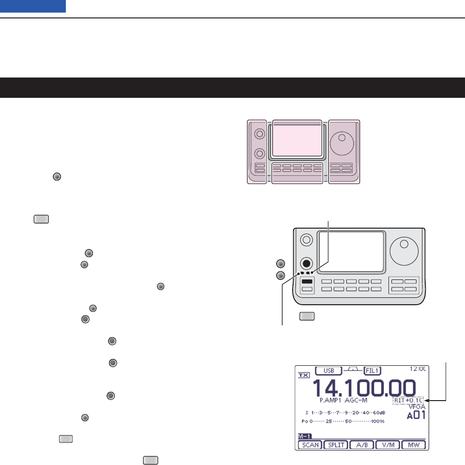
5FUNCTIONS FOR RECEIVE
5-4
Previous view
RIT function
The RIT (Receive Increment Tuning) function compen-
sates for slight frequency differences between the two
stations.
The function shifts the receive frequency up to
±9.99 kHz in 10 Hz steps*, without changing the trans-
mit frequency.
* The [M-CH] (L) control tunes in 1 Hz steps when
the operating frequency readout is set to the 1 Hz step
readout.
Push q
RIT
(L) to turn ON the RIT function.
• “RIT” and the frequency shift appear when this function is
ON.
Rotate the [M-CH] w(L) control.
• When the [M-CH] (L) control acts as the RIT control,
the RIT LED lights orange.
If the RIT LED is OFF, push the [M-CH] (L) switch one
or more times to turn it ON.
• Pushing the [M-CH] (L) switch to select the action of
the [M-CH/BANK] (L) controls as the Memory/Bank
selection, PBT control or RIT control.
- When the [M-CH/BANK] (L) controls act as the PBT
control, the PBT LED lights green.
- When the [M-CH/BANK] (L) controls act as the RIT
control, the RIT LED lights orange. (The RIT control is
the inner control. The outer control is disabled.)
- When the [M-CH/BANK] (L) controls act as the Mem-
ory/Bank selection, both LEDs are OFF.
• Hold down [CLR] (L) for 1 second to reset the RIT
frequency.
• Hold down
RIT
(L) for 1 second to add the frequency
shift to the operating frequency.
e To cancel the RIT function, push
RIT
(L) again.
• “RIT” and the frequency shift disappear.
The L, R, C or D in the
instructions indicate the
part of the controller.
L: Left side
R: Right side
C: Center bottom
D: Display (Touch panel)
Left Right
Center
Display
RIT
[M-CH]
[CLR]
RIT LED lights orange
PBT LED lights green
RIT frequency display
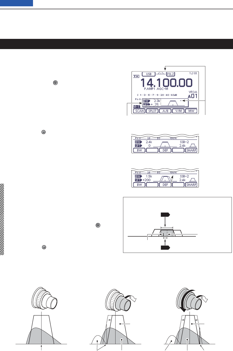
5FUNCTIONS FOR RECEIVE
5-5
Previous view
(Mode: SSB/CW/RTTY/AM
)
To reject interference, PBT (Passband Tuning) electron-
ically narrows the IF passband width by shifting the IF
frequency slightly outside of the IF fi lter passband. The
IC-7100 uses DSP for the PBT function. Moving both
TWIN-PBT ([M-CH/BANK] (L)) controls shifts the IF
passband center frequency both above and below the
received frequency.
The LCD graphically shows the passband width and ➥
frequency shift.
Touch the Filter icon for 1 second to display the “FIL- ➥
TER” screen. The current passband width and fre-
quency shift are displayed.
Hold down [CLR] ➥(L) for 1 second to set the IF
frequency to the center position.
• The “dots” disappear.
The PBT is adjustable in 50 Hz steps in the SSB/CW/
RTTY modes, and 200 Hz in the AM mode.
When adjusting, the shift value changes in 25 Hz steps
in the SSB/CW/RTTY modes, and 100 Hz in the AM
mode.
• The TWIN-PBT controls should normally be set to
the center positions when there is no interference.
The PBT setting should be cleared.
• When the PBT is used, the audio tone may
change.
• The controls do not function in the FM, WFM and
DV modes.
• While rotating the TWIN-PBT ([M-CH/BANK] (L))
controls, noise may occur. This comes from the
DSP unit and does not indicate an equipment mal-
function.
• Pushing [M-CH]] (L) displays the fi lter passband
width and shift value for 1 second.
Twin PBT operation
PBT2
PBT1
PBT2
PBT1
PBT2
PBT1
Both controls in the
center positions
Cutting the lower
passband edge
Cutting both lower and
higher passband edges
PBT OPERATION EXAMPLE
IF center frequency Interference Interference InterferenceDesired signal
Passband Passband
Desired signal
Passband width and shift value are dis-
played while the TWIN PBT is used.
Appear when pass-
band is shifted.
• “FILTER” screen display
• While adjusting the PBT setting
A dot appears when the passband is shifted.
Shows the selected fi lter and passband width.
• About Passband width and Shift value
on the screen
SFT
BW
: Shift value
IF center
frequency
Passband’s
center frequency
: Passband width
( Width of () in which
the two PBTs overlap)
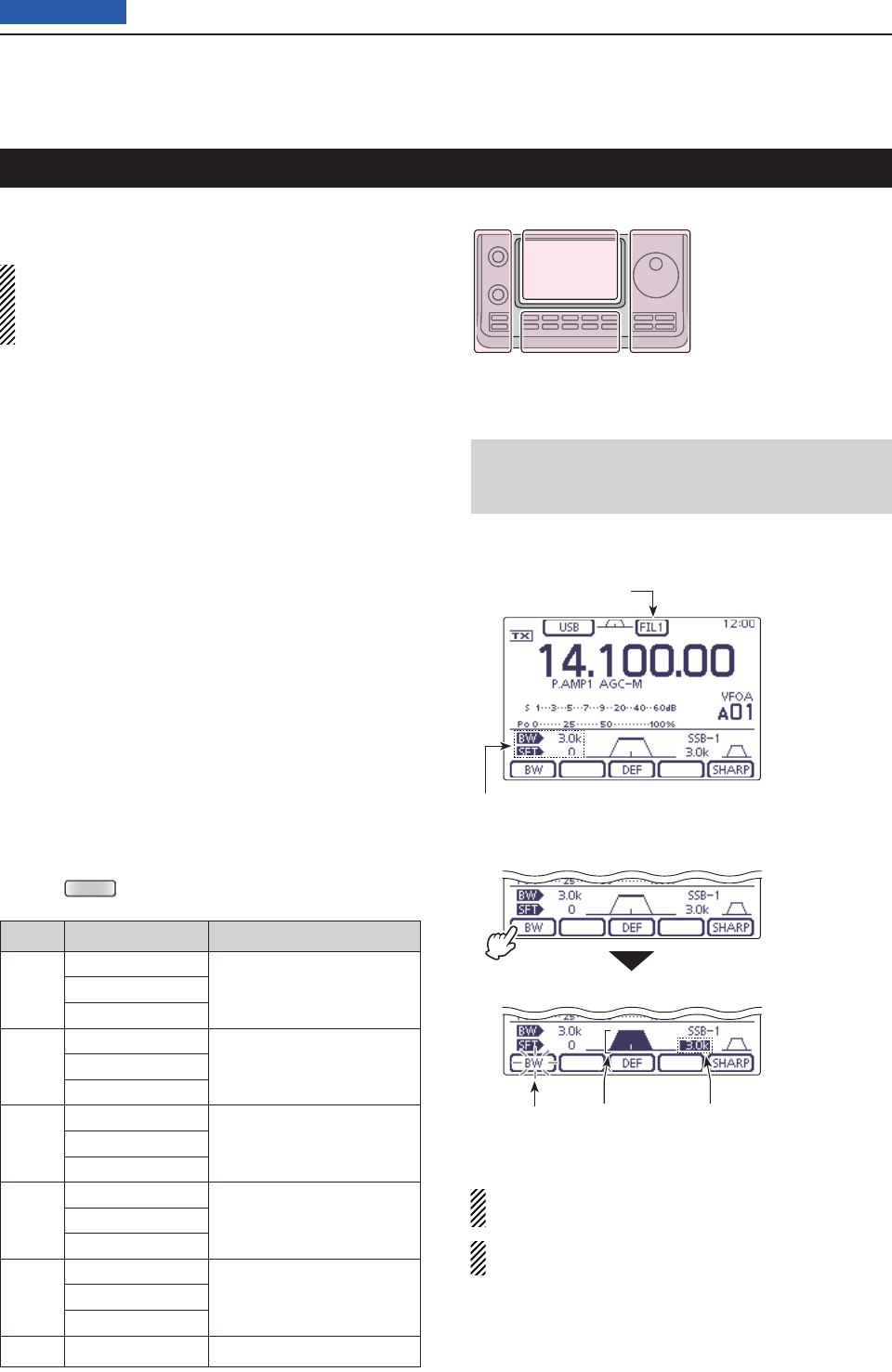
5FUNCTIONS FOR RECEIVE
5-6
Previous view
The transceiver has 3 passband width IF fi lters for each
mode.
The fi lter selection is automatically memorized in
each mode.
The PBT shift frequencies are automatically memo-
rized in each fi lter.
IF fi lter selection D
On the Mode selection screen, select the desired q
mode. (p. 3-??)
Touch the Filter icon one or more times to select IF w
fi lter 1, 2 or 3.
• The selected passband width and fi lter number is dis-
played as the Filter icon.
Filter passband width setting D
(Mode: SSB/CW/RTTY/AM)
On the Mode selection screen, select the desired q
mode. (p.3-??)
• Passband widths for FM, WFM and DV modes are fi xed,
and cannot be adjusted.
Touch the Filter icon for 1 second to display the “FIL- w
TER” screen to adjust the fi lter passband width.
Touch the Filter icon one or more times to select IF e
fi lter 1, 2 or 3.
Touch [BW]( rD), then rotate the Dial to adjust the de-
sired passband width.
Then touch
[BW](D)
to set it.
• If desired, touch [DEF](D) for 1 second to reset to the
default setting.
If desired, select another mode (any other than the t
FM, WFM or DV), then repeat steps w and r.
Push y
MENU
(C) to exit the “FILTER” screen.
Mode IF fi lter Adjustable range (steps)
SSB
FILTER1 (3.0 kHz)
50 to 500 Hz (50 Hz)
600 Hz to 3.6 kHz (100 Hz)
FILTER2 (2.4 kHz)
FILTER3 (1.8 kHz)
SSB-D
CW
FILTER1 (1.2 kHz)
50 to 500 Hz (50 Hz)
600 to 3600 Hz (100 Hz)
FILTER2 (500 Hz)
FILTER3 (250 Hz)
RTTY
FILTER1 (2.4 kHz)
50 to 500 Hz (50 Hz)
600 to 2700 Hz (100 Hz)
FILTER2 (500 Hz)
FILTER3 (250 Hz)
AM
AM-D
FILTER1 (9.0 kHz)
200 Hz to 10 kHz (200 Hz)
FILTER2 (6.0 kHz)
FILTER3 (3.0 kHz)
FM
FM-D
DV
FILTER1 (15 kHz)
Fixed
FILTER2 (10 kHz)
FILTER3 (7.0 kHz)
WFM FILTER (280 kHz) Fixed
IF fi lter selection
When FILTER2 or FILTER3 is selected in the FM
mode, the TX modulation changes to the narrow FM
mode (2.5 kHz).
The PBT shift frequencies are cleared when the
passband width is changed.
This “FIL” screen (Filter) graphically displays the PBT
shift frequencies and passband width.
• “FILTER” screen display
• While adjusting the passband width
Filter icon
Passband width and shift value
Blinks Highlighted Highlighted
Touch [BW]
Rotate the Dial to
adjust the pass-
band width, and
then touch [BW]
The L, R, C or D in the
instructions indicate the
part of the controller.
L: Left side
R: Right side
C: Center bottom
D: Display (Touch panel)
Left Right
Center
Display
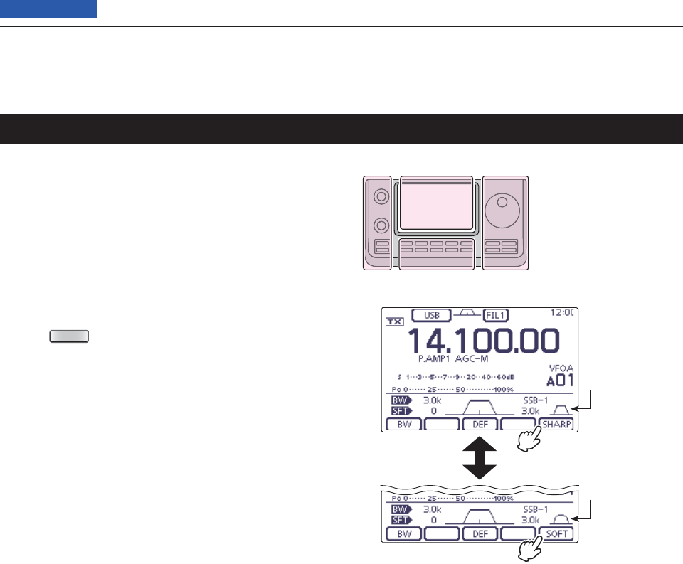
5FUNCTIONS FOR RECEIVE
5-7
Previous view
(Mode: SSB/CW
)
A soft or sharp type of DSP fi lter shape for both SSB
and CW can be independently selected.
On the Mode selection screen, select the SSB or q
CW mode. (p. 3-??)
Touch the Filter icon for 1 second to display the “FIL- w
TER” screen.
Touch [SHARP] or [SOFT]( eD) to select either the
soft or sharp fi lter shape.
Push r
MENU
(C) to exit the “FILTER” screen.
IF (DSP) fi lter shape
When SHARP is
selected
When SOFT is
selected
Touch [SHARP]
to select SOFT
Touch [SOFT] to
select SHARP
The L, R, C or D in the
instructions indicate the
part of the controller.
L: Left side
R: Right side
C: Center bottom
D: Display (Touch panel)
Left Right
Center
Display
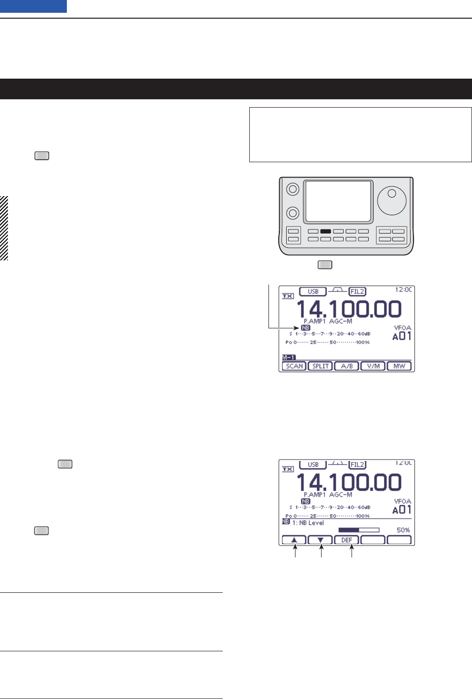
5FUNCTIONS FOR RECEIVE
5-8
Previous view
(Mode: SSB/CW/RTTY/AM
)
The Noise Blanker eliminates pulse-type noise such as
noise from car ignitions.
Push ➥
NB
(D) to turn the Noise Blanker function ON
or OFF.
•
“NB” is displayed when the
Noise Blanker
is ON.
When using the Noise Blanker function, received
signals may be distorted if they are excessively
strong or when the function is used for noise other
than pulses. In this case, set the Noise Blanker
threshold level to a shallow position, or turn OFF the
function. (See below.)
Noise Blanker
NB Set mode D
To deal with various types of noise, the attenuation
level and noise blanking duration can be set in the NB
set mode.
Hold down q
NB
(C) for 1 second to display the “NB”
screen (Noise blanker).
Touch [ wY] or [Z](D) to select the desired item.
Rotate the Dial eto select the desired option.
• If desired, touch [DEF](D) for 1 second to reset to the
default setting.
Push r
NB
(C) to
return to the previous screen.
1. NB Level (Default: 50%)
Set the noise blanker threshold level to between 0%
and 100%.
2. NB Depth (Default: 8)
Set the noise attenuation level to between 1 and 10.
3. NB Width (Default: 50)
Set the blanking duration to between 1 and 100.
NB
The L, R, C or D in the instructions indicate the
part of the controller.
L: Left side, R: Right side, C: Center bottom
D: Display (Touch panel)
NB icon
Select the item Touch for 1 second
to reset to default
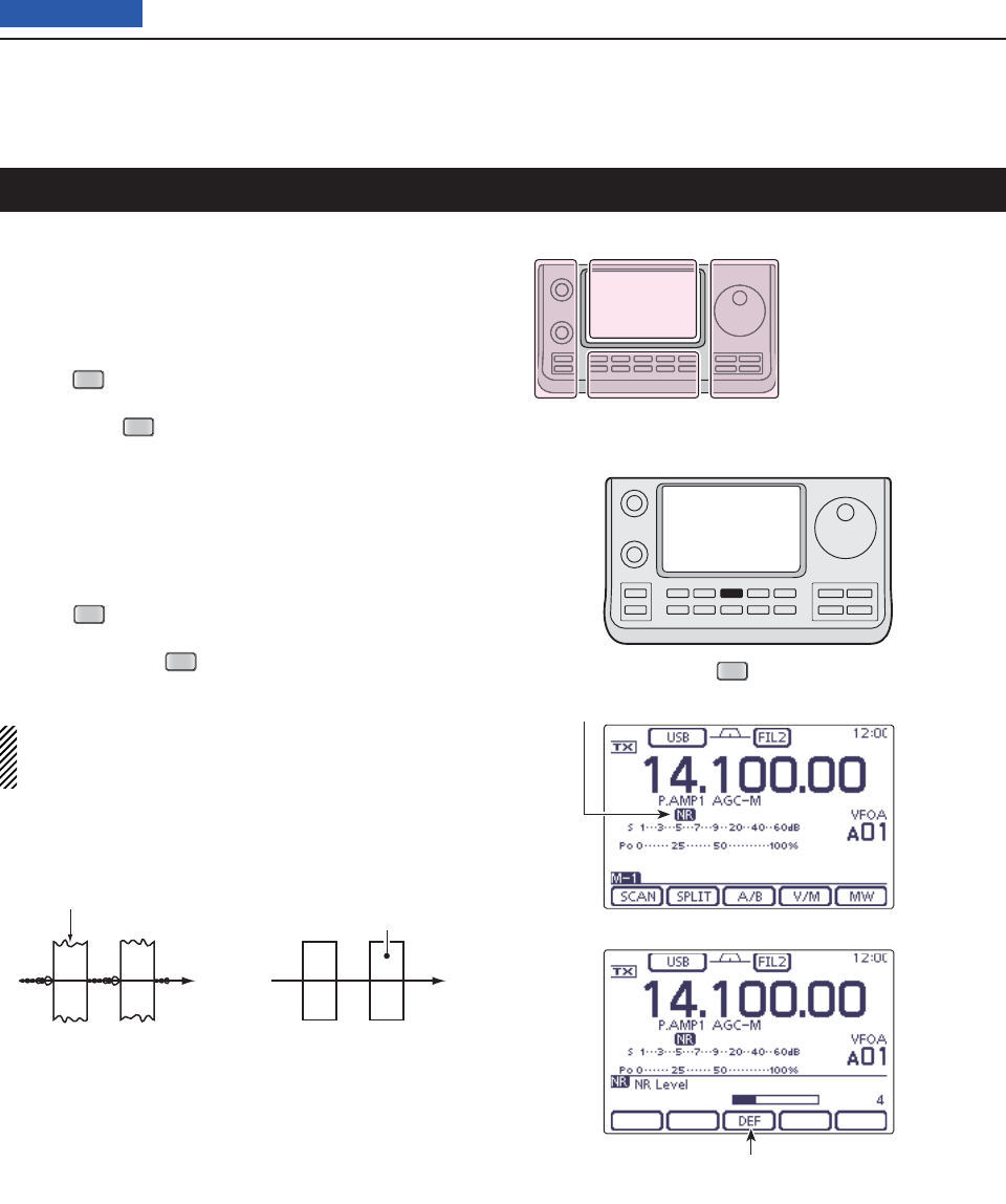
5FUNCTIONS FOR RECEIVE
5-9
Previous view
NR
Noise Reduction
The Noise Reduction function reduces random noise
components and enhances audio signals which are
buried in noise. The received signals are converted to
digital signals and then the audio signals are separated
from the noise.
Push q
NR
(C) to turn ON the Noise Reduction.
• “NR” appears.
Hold down w
NR
(C) for 1 second to display the “NR”
screen (Noise Reduction).
Rotate the Dial eto adjust the Noise Reduction lev-
el; rotate it clockwise to increase reduction level or
counterclockwise to decrease reduction level.
• If desired, touch [DEF](D) for 1 second to reset to the
default setting.
• The adjustable reduction level is between 1 and 15.
Push r
NR
(C) to
exit the
“NR” screen (Noise Reduc-
tion)
.
• If desired, push
NR
(C) to turn OFF the Noise Reduc-
tion.
A large rotation of the “NR control” results in audio
signal masking or distortion. Set the “NR control” for
maximum readability.
Noise reduction ONNoise reduction OFF
Desired
signal (CW)
Noise components
The L, R, C or D in the
instructions indicate the
part of the controller.
L: Left side
R: Right side
C: Center bottom
D: Display (Touch panel)
Left Right
Center
Display
NR icon
Touch for 1 second
to reset to default
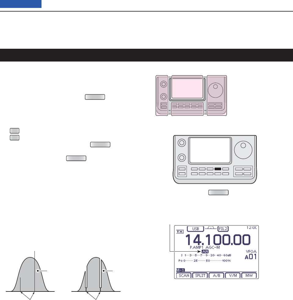
5FUNCTIONS FOR RECEIVE
5-10
Previous view
(Mode = Auto notch: SSB/AM/FM
Manual notch: SSB/CW/RTTY/AM)
This transceiver has Auto and Manual Notch functions.
➥
In the SSB or AM mode, push
NOTCH
(C) to toggle
the Notch function between auto, manual and OFF.
• Either the Auto or Manual notch function can be turned
OFF in the “[NOTCH] switch (SSB)” or “[NOTCH] switch
(AM)” item of the “Function” Set mode. (p. 165)
SET
(C) > Function > [NOTCH] switch (SSB)
SET
(C) > Function > [NOTCH] switch (AM)
In the CW or RTTY mode, push ➥
NOTCH
(C)
to turn
the Manual Notch function ON or OFF.
In the FM mode, push ➥
NOTCH
(C)
to turn the Auto
Notch function ON or OFF.
• “AN” appears when the Auto Notch function is ON.
• “MN” appears when the Manual Notch function is ON.
• No indicator appears when the notch fi lter is OFF.
Auto Notch function D
The Auto Notch function uses DSP to automatically at-
tenuate beat tones, tuning signals, and so on, even if
their frequencies are changing.
Notch function
NOTCH
Auto Notch is OFF Auto Notch is ON
Desired
signal (AF)
Desired
signal (AF)
Unwanted interference Interference frequency
is attenuated
The L, R, C or D in the
instructions indicate the
part of the controller.
L: Left side
R: Right side
C: Center bottom
D: Display (Touch panel)
Left Right
Center
Display
Auto Notch icon
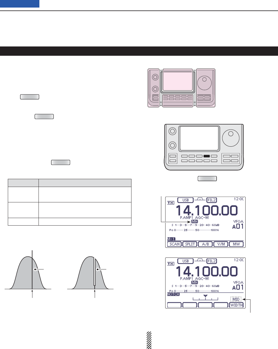
5FUNCTIONS FOR RECEIVE
5-11
Previous view
Manual Notch function D
(Mode = Manual notch: SSB/CW/RTTY/AM)
The Manual Notch function allows you to manually at-
tenuate a frequency using the ‘NOTCH control.’
Push q
NOTCH
(C) once or twice to turn ON the Man-
ual Notch function.
• “MN” appears.
Hold down w
NOTCH
(C) for 1 second to display the
“NOTCH” screen.
• Touch [WIDTH](D) to select the Manual Notch fi lter width,
“WIDE,” “MID” or “NAR.”
Rotate the Dial eto adjust the Notch fi lter frequency.
• Since the Notch fi lter has the very sharp characteristic,
slowly rotate the Dial when adjusting a fi lter.
• If desired, push
NOTCH
(C) to
exit the
“NOTCH”
screen
.
Mode Center frequency
SSB
RTTY –1040 Hz to +4040 Hz
CW CW pitch frequency –2540Hz to
CW pitch frequency +2540Hz
AM –5060 Hz to +5100 Hz
Notch function (Continued)
While tuning the manual notch fi lter, noise may be
heard. This comes from the DSP unit and does not
indicate an equipment malfunction.
Manual Notch is OFF Manual Notch is ON
Desired
signal (AF)
Desired
signal (AF)
Unwanted interference Interference frequency
is attenuated
NOTCH
The L, R, C or D in the
instructions indicate the
part of the controller.
L: Left side
R: Right side
C: Center bottom
D: Display (Touch panel)
Left Right
Center
Display
Manual Notch fi lter width
Manual Notch icon
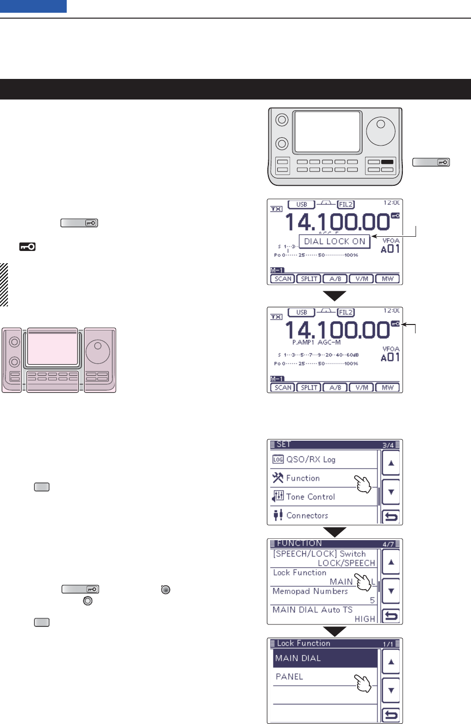
5FUNCTIONS FOR RECEIVE
5-12
Previous view
The IC-7100 has two kinds of lock functions; Dial Lock
and Panel Lock. The Dial Lock function locks only the
Dial, and Panel Lock function locks controller opera-
tion.
The Dial Lock function prevents frequency changes by
accidental movement of the Dial by electronically lock-
ing it. To prevent accidental frequency changes and un-
necessary function access, use the Panel Lock func-
tion.
➥ Hold down
SPEECH
(R) to turn the Lock function
ON or OFF.
• “ ” appears when the function is ON.
NOTE: When the “[SPEECH/LOCK] Switch” item of
the “Function” Set mode is set to “LOCK/SPEECH,”
pushing [SPEECH/LOCK] turns ON the Dial Lock
function. (p. 164)
Lock function
SPEECH
Selecting the Lock type D
The Lock function is set to MAIN DIAL by default. The
setting can be changed to PANEL in the “Lock Func-
tion” item of the “Function” Set mode. (p. 165)
Push q
SET
(C) to enter the Set mode.
Touch the “Lock Function” item of the “Function” Set w
mode.
Function > Lock Function
• If the specifi ed item is not displayed, touch [Y] or [Z](D)
one or more times to select the page.
Touch the desired option to set the Lock type. e
• MAIN DIAL: Locks only the Dial operation.
• PANEL: Locks the Dial, controls and keys.
SPEECH
(R), [PWR/AF] (L) and [RF/
SQL] (L) can be used while in the Panel
Lock function is ON.
Push r
SET
(C) to exit the Set mode.
The L, R, C or D in the
instructions indicate the
part of the controller.
L: Left side
R: Right side
C: Center bottom
D: Display (Touch panel)
Left Right
Center
Display
Lock icon
Popup window
Touch the option
Example: PANEL
Touch “Function”
Touch
“Lock Function”
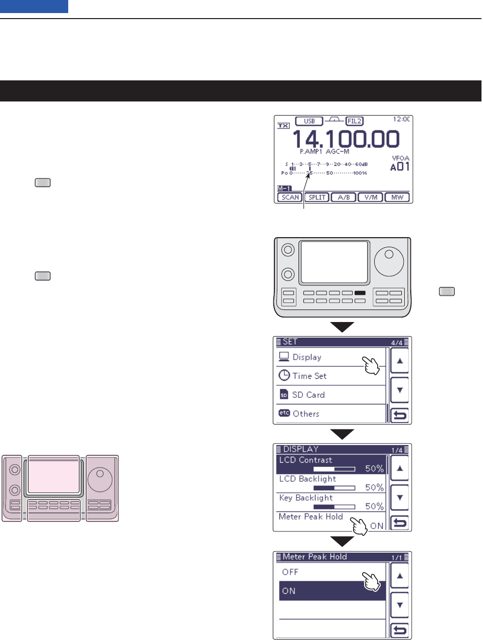
5FUNCTIONS FOR RECEIVE
5-13
Previous view
Meter peak hold function
Appears for 0.5 seconds.
The Meter Peak hold function is set to ON by default,
the peak level of a received signal strength or the out-
put power is displayed for approximately 0.5 seconds.
The function can be turned OFF in the “Meter Peak
Hold” item of the “Display” Set mode. (p. 165)
Push q
SET
(C) to enter the Set mode.
Touch the “Meter Peak Hold” item of the “Display” w
Set mode.
Display > Meter Peak Hold
• If the specifi ed item is not displayed, touch [Y] or [Z](D)
one or more times to select the page.
Touch the desired option to turn ON or OFF the Me- e
ter Peak Hold function.
Push r
SET
(C) to exit the Set mode.
The L, R, C or D in the
instructions indicate the
part of the controller.
L: Left side
R: Right side
C: Center bottom
D: Display (Touch panel)
Left Right
Center
Display
Touch the option
Example: OFF
Push
SET
Touch “Display”
Touch
“Meter Peak Hold”
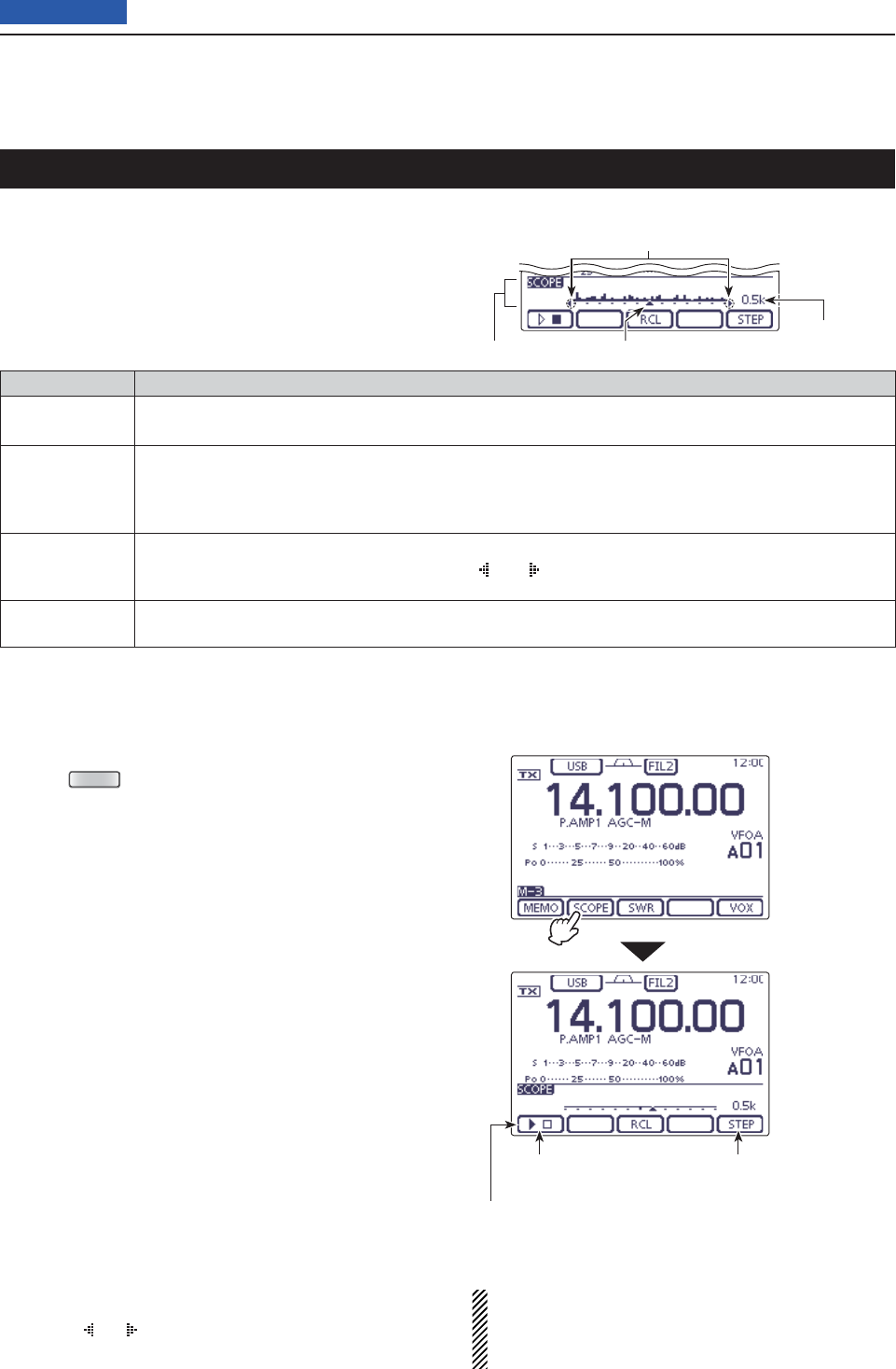
5FUNCTIONS FOR RECEIVE
5-14
Previous view
Simple Band Scope
The Band Scope function allows you to visually check
the location and strength of signals around a specifi ed
frequency.
The IC-7100’s Band Scope function can be used in any
operating mode and any frequency band.
INDICATOR DESCRIPTION
Sweep icon While the band scope is sweeping, “” is displayed; while stopped, “” is displayed.
Received audio is not heard from the speaker while the band scope is sweeping.
Band scope
display
Displays the signal location and strength in relation to the center (displayed) frequency. Signal
strength is relative to the S-meter level, S1 to S9+30 dB, with each vertical dot in the band scope
indicators 1 to 15 dots. Between +30 dB to +60 dB are also displayed by 15 dots. Signal activity is
measured ±30 steps from the center frequency, with each step equal to the selected sweep step.
Frequency
display mark
After a sweep, displays the relative position of the reference frequency. When the reference
frequency is outside of the sweep range, “ ” or “ ” blinks. After changing the frequency, touch
[RCL](D) for 1 second to automatically return to the center frequency.
Sweep step
display
Displays the selected sweep step. Steps of 0.5, 1, 2, 5, 10, 20 and 25 kHz are selectable. Each dot
of the band scope display is equal to the selected sweep step.
The band scope displays the receive signal location and
strength over a specifi ed range on either side of a selected
frequency, in either the VFO or memory modes.
Rotate the Dial to select a frequency. q
Push w
MENU
(C) one or more times to select the
“M-3” screen (M-3 menu).
Touch [SCOPE]( eD) for 1 second to display the
“SCOPE” screen (Band Scope).
• Automatically starts sweeping with the previously select-
ed sweeping step.
• During a sweep, received signals cannot be heard.
Touch [STEP]( rD) one or more times to select the
desired sweep step.
• 0.5, 1, 2, 5, 10, 20 and 25 kHz are selectable.
Touch [ t](D) to start sweeping, then automati-
cally stop after sweeping.
• Touch [](D) for 1 second to start continuous sweep-
ing. In this case, touch [](D) to stop the sweeping.
• During a sweep, “” is displayed but received signals
cannot be heard.
• If there is a lot of signal noise, turn OFF the Preamplifi er
to reduce the signal input level, and, if necessary, turn
ON the Attenuator to improve the readability of the band
scope.
Rotate the Dial to fi nd a signal that you wish to com- y
municate with. If you fi nd the signal, communicate in
the normal way.
• If you want to return to the frequency you were using
before rotating the Dial, touch [RCL](D) for 1 second.
• If the selected frequency is set outside of the sweep
range, “ ” or “ ” blinks.
If you want to update the band conditions while re- u
ceiving, repeat steps r and t.
NOTE:
If you select a large sweep step, a wide frequency
range can be displayed on the band scope, but some
signals may be skipped and not displayed.
Touch [SCOPE]
Band scope display
Sweep start/stop Sweep step selection
Sweep icon
Sweep step
display
Frequency display mark
Blinks when the reference frequency
is outside of the sweep range.

VOX function ............................................................................6-2
Using the VOX function D ...........................................................6-2
Adjusting the VOX function D ......................................................6-2
Break-in function .....................................................................6-3
Semi Break-in operation D ..........................................................6-3
Full Break-in operation D ............................................................6-4
Speech compressor function .................................................6-5
Transmit fi lter width selection ................................................6-6
Monitor function ......................................................................6-7
Split frequency operation .......................................................6-8
Direct frequency shift input D ...................................................... 6-9
Split Lock function D ...................................................................6-10
Quick Split function .................................................................6-11
Split frequency offset setting D ...................................................6-12
Measuring SWR .......................................................................6-13
Spot measurement D ..................................................................6-13
Plot measurement D ...................................................................6-14
SWR Graph Set mode D .............................................................6-16
DTMF Memory encoder ...........................................................6-17
Programming a DTMF code D ....................................................6-17
Transmitting DTMF code D .........................................................6-18
Transmitting DTMF code (Direct Input) D ...................................6-19
Setting DTMF transfer speed D ..................................................6-20
6-1
Section 6FUNCTIONS FOR TRANSMIT
Previous view
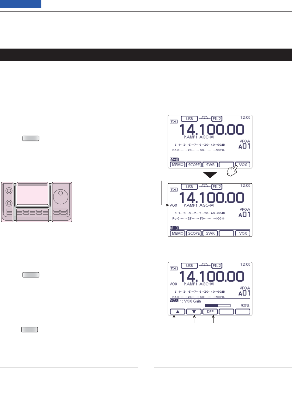
6FUNCTIONS FOR TRANSMIT
6-2
Previous view
(Mode: SSB/AM/FM/DV)
The VOX (Voice-Operated Transmission) function
switches the transceiver between transmit and receive
with your voice. This function provides hands-free op-
eration.
Using the VOX function D
Select the desired frequency band. (p. 35) q
On the Mode selection screen, select either the SSB, w
AM, FM or DV mode. (p.3-??)
Push e
MENU
(C) one or more times to select the
“M-3” screen (M-3 menu).
Touch [VOX]( rD)
to turn ON the VOX function.
• “VOX” appears.
VOX function
1. VOX Gain (Default: 50%)
Adjust the VOX gain to between 0% and 100%, in 1%
steps.
Higher values make the VOX function more sensitive
to your voice.
2. Anti-VOX (Default: 50%)
Adjust the ANTI-VOX gain to between 0% and 100%,
in 1% steps.
Higher values make the VOX function less sensitive to
the received audio from a speaker or headphones.
3. VOX Delay (Default: 0.2sec)
Set the VOX delay to between 0.0 and 2.0 seconds, for
normal pauses in speech before returning to receive.
Adjusting the VOX function D
On the Mode selection screen, select either the SSB, q
AM, FM or DV mode. (p.3-??)
Push w
MENU
(C) one or more times to select the
“M-3” screen (M-3 menu).
Touch [VOX]( eD) for 1 second to display the “VOX”
screen
.
Touch [ rY] or [Z](D) to select the desired item.
Rotate the Dial tto select the desired option.
• If desired, touch [DEF](D) for 1 second to reset to the
default setting.
Push y
MENU
(C) to exit the “VOX” screen.
The L, R, C or D in the
instructions indicate the
part of the controller.
L: Left side
R: Right side
C: Center bottom
D: Display (Touch panel)
Left Right
Center
Display VOX icon
Touch [VOX]
Select the item Touch for 1 second
to reset to default
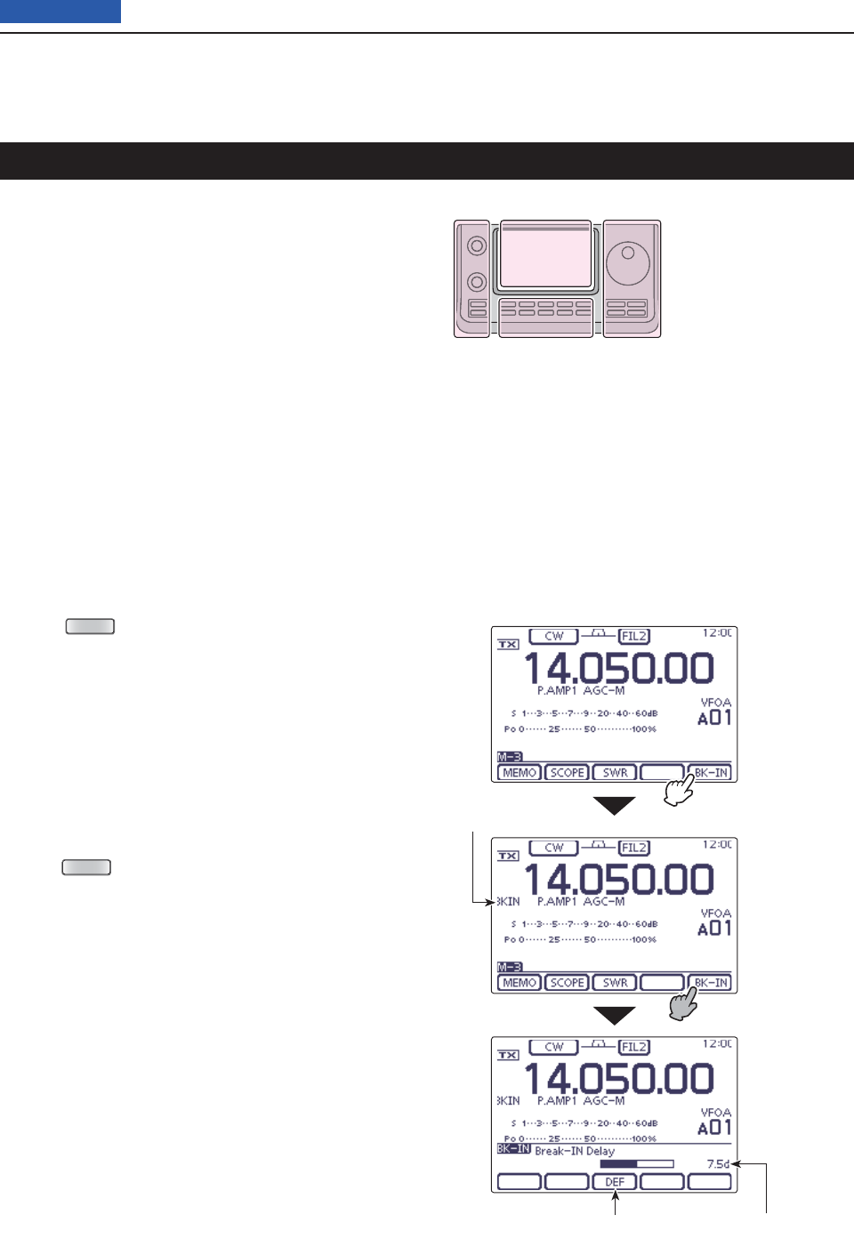
6FUNCTIONS FOR TRANSMIT
6-3
Previous view
Break-in function
(Mode: CW
)
The Break-in function is used in the CW mode to auto-
matically toggle the transceiver between transmit and
receive when keying. The IC-7100 is capable of Full
Break-in or Semi Break-in.
Semi Break-in operation D
During Semi Break-in operation, the transceiver imme-
diately transmits when you key down, then returns to
receive after a preset delay time has passed after you
stop keying.
Select the desired frequency band. (p. 3-5) q
On the Mode selection screen, select the CW or w
CW-R mode. (p.3-??)
Push e
MENU
(C) one or more times to select the
“M-3” screen (M-3 menu).
Touch [BK-IN]( rD) one or more times
to turn ON the
Semi Break-in function.
• “BKIN” appears.
When the “M-3” screen (M-3 menu) is selected, t
touch [BK-IN](D) for 1 second to display the “BK-IN”
screen.
Touch [ yY] or [Z](D) to select the desired item.
Rotate the Dial uto select the desired option.
• If desired, touch [DEF](D) for 1 second to reset to the
default setting.
Push i
MENU
(C) to exit the “BK-IN” screen.
The L, R, C or D in the
instructions indicate the
part of the controller.
L: Left side
R: Right side
C: Center bottom
D: Display (Touch panel)
Left Right
Center
Display
Touch [BK-IN]
Touch for 1 second
to reset to default
Semi Break-in icon
Shows break-in delay time
Touch [BK-IN]
for 1 second
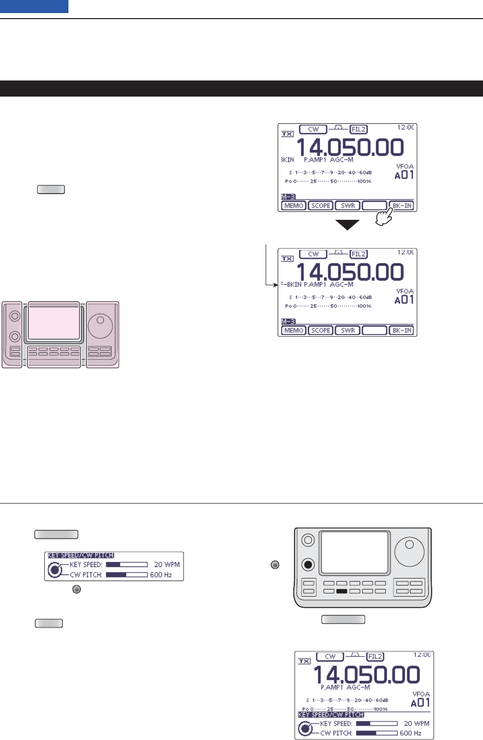
6FUNCTIONS FOR TRANSMIT
6-4
Previous view
Break-in function (Continued)
Push q
SPEED/PITCH
(C) to open the Key speed/CW pitch
adjustment window.
Rotate [M-CH] w(L) to adjust the Key speed.
• The adjustable key speed is between 6 and 48 wpm
(words per minute).
Push e
MENU
(C) to close the window.
SPEED/PITCH
[M-CH]
When using a paddle:
Adjust the keying speed while operating a paddle.
Full Break-in operation D
During Full Break-in operation, the transceiver trans-
mits when you key down, then immediately returns to
receive when you release.
On the Mode selection screen, select the CW or q
CW-R mode. (p.3-??)
Push w
MENU
(C) one or more times to select the
“M-3” screen (M-3 menu).
Touch [BK-IN]( eD) one or more times
to turn ON the
Full Break-in function.
• “F-BKIN” appears. Full Break-in icon
Touch [BK-IN]
The L, R, C or D in the
instructions indicate the
part of the controller.
L: Left side
R: Right side
C: Center bottom
D: Display (Touch panel)
Left Right
Center
Display
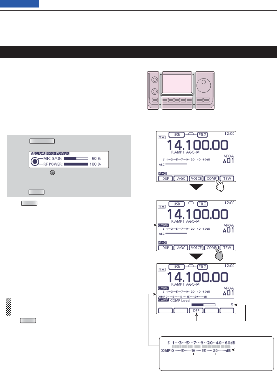
6FUNCTIONS FOR TRANSMIT
6-5
Previous view
Speech compressor function
(Mode: SSB
)
The Speech Compressor function increases average
RF output power, improving signal strength and read-
ability.
Select the desired frequency band. (p. 3-5) q
On the Mode selection screen, select the USB or w
LSB mode. (p.3-??)
Before fi rst tuning ON the Speech compressor, adjust e
the microphone gain so that the ALC meter reading
stays within the ALC zone.
q Push
MIC/RF PWR
(C) to open the MIC gain/RF
power adjustment display.
w Rotate [M-CH] (L) to adjust the MIC gain.
• To adjust the MIC gain, touch the TX meter to select
the ALC meter.
e Push
MENU
(C) to close the display.
Push r
MENU
(C) one or more times to select the
“M-2” screen (M-2 menu).
Touch [COMP]( tD)
to turn ON the Speech Compres-
sor.
• “COMP” appears.
Touch [COMP]( yD) for 1 second
to display the “COMP”
(Compressor) screen.
While speaking into the microphone at your normal u
voice level, rotate the Dial so that the COMP meter
reading stays within the COMP level zone (10 dB to
20 dB zone).
• To adjust the COMP level, touch the TX meter to select
the COMP meter.
• If desired, touch [DEF] for 1 second to reset to the default
setting.
When the COMP meter peaks above the COMP
level zone, your transmitted voice may be distort-
ed.
Push i
MENU
(C) to exit the “COMP” screen.
The L, R, C or D in the
instructions indicate the
part of the controller.
L: Left side
R: Right side
C: Center bottom
D: Display (Touch panel)
Left Right
Center
Display
Touch [COMP]
Touch for 1 second
to reset to default
Touch [COMP]
for 1 second
Speech Compressor icon
Shows the compression level
COMP level zone
(10 dB to 20 dB)
COMP meter
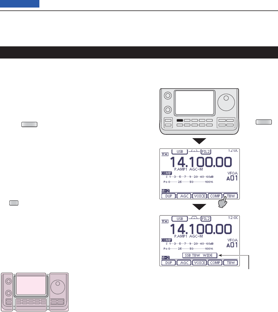
6FUNCTIONS FOR TRANSMIT
6-6
Previous view
Transmit fi lter width selection
(Mode: SSB
)
The transmit fi lter width for the SSB mode can be se-
lected from Wide, Mid or Narrow. This setting can be
memorized each for the Speech Compressor ON and
OFF.
Select the desired frequency band. (p. 3-5) q
On the Mode selection screen, select the USB or w
LSB mode. (p.3-??)
Push e
MENU
(C) one or more times to select the
“M-2” screen (M-2 menu).
Touch [COMP]( rD)
to turn ON the Speech Compres-
sor.
• “COMP” appears.
Touch [TBW]( tD) for 1 second one or more times a
Wide, Mid or Narrow transmission passband width
.
• Touch [TBW](D) to display the selected TX fi lter width for
approximately 1 second.
• The following fi lters are specifi ed as the defaults. Each of
the fi lter widths can be set in the “TBW” items of the “Tone
Control” Set mode. (p. 165)
SET
(C) > Tone Control > TX > SSB
> TBW (WIDE), TBW (MID), TBW (NAR)
- WIDE: 100 Hz to 2900 Hz
- MID: 300 Hz to 2700 Hz
- NAR: 500 Hz to 2500 Hz
The L, R, C or D in the
instructions indicate the
part of the controller.
L: Left side
R: Right side
C: Center bottom
D: Display (Touch panel)
Left Right
Center
Display
Touch [TBW] for
1 second
Push
MENU
The selected transmit fi lter width is
displayed for approximately 1 second.
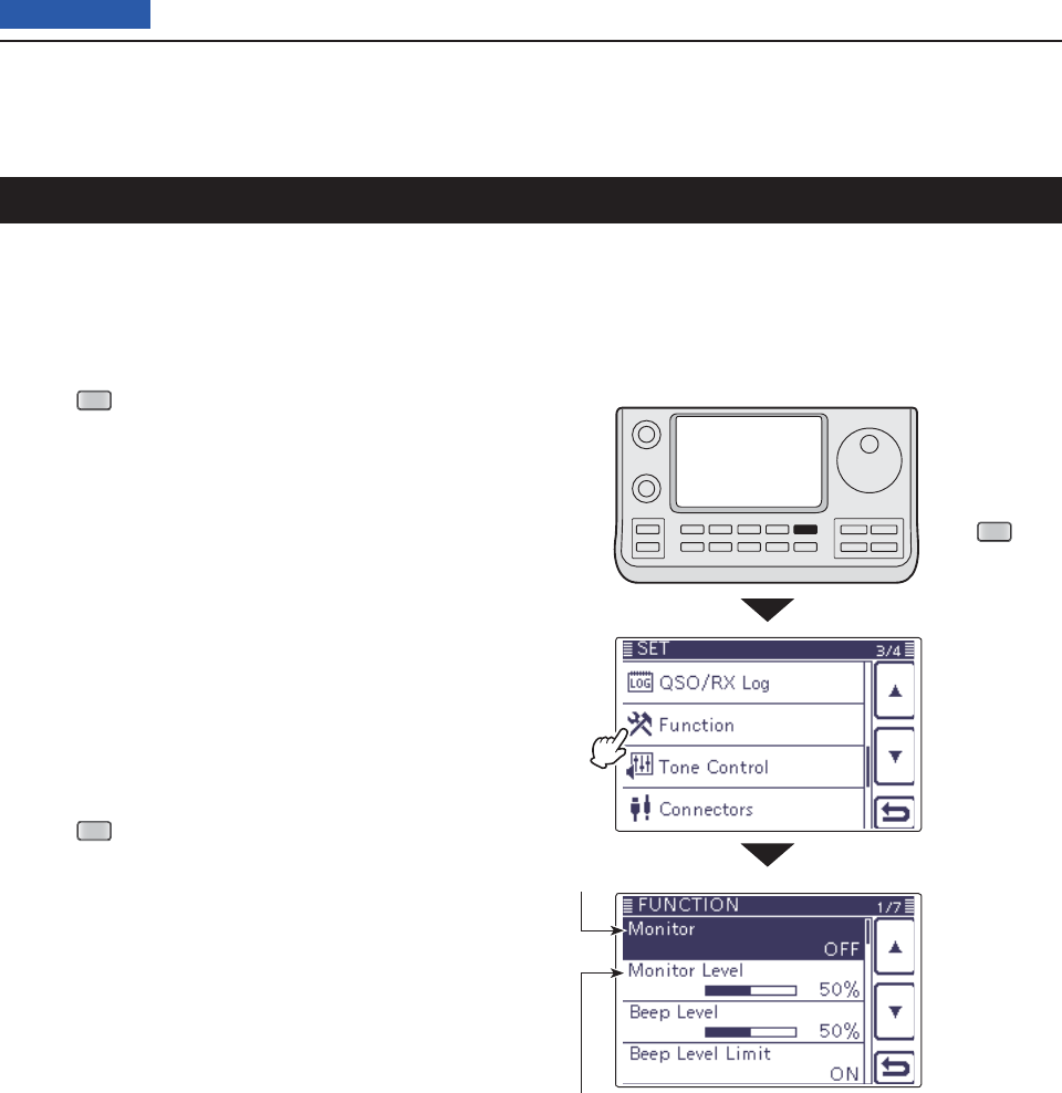
6FUNCTIONS FOR TRANSMIT
6-7
Previous view
Monitor function
The Monitor function allows you to monitor your trans-
mit IF signals in any mode. Use this to check voice
characteristics while adjusting transmit parameters.
The CW sidetone functions regardless of the “Monitor”
setting.
Push q
SET
(C) to enter the Set mode.
Touch the “Monitor” item of the “Function” Set mode. w
Function > Monitor
• If the specifi ed item is not displayed, touch [Y] or [Z](D)
one or more times to select the page.
Touch the option to turn ON the function. e
Touch the “Monitor Level” item of the “Function” Set r
mode.
Function > Monitor Level
Rotate the Dial to adjust the monitor level. t
• For the clearest audio output, adjust while holding
down [PTT] and speaking into the microphone.
• The adjustable monitor level is between 0% (minimum
audio level) and 100% (maximum audio level).
• If desired, touch the level bar for 1 second to open the
Default set window, then select “Default” to reset to the
default setting.
Push y
SET
(C) to exit the Set mode.
Monitor ON/OFF
Monitor level
Touch
“Function”
Push
SET
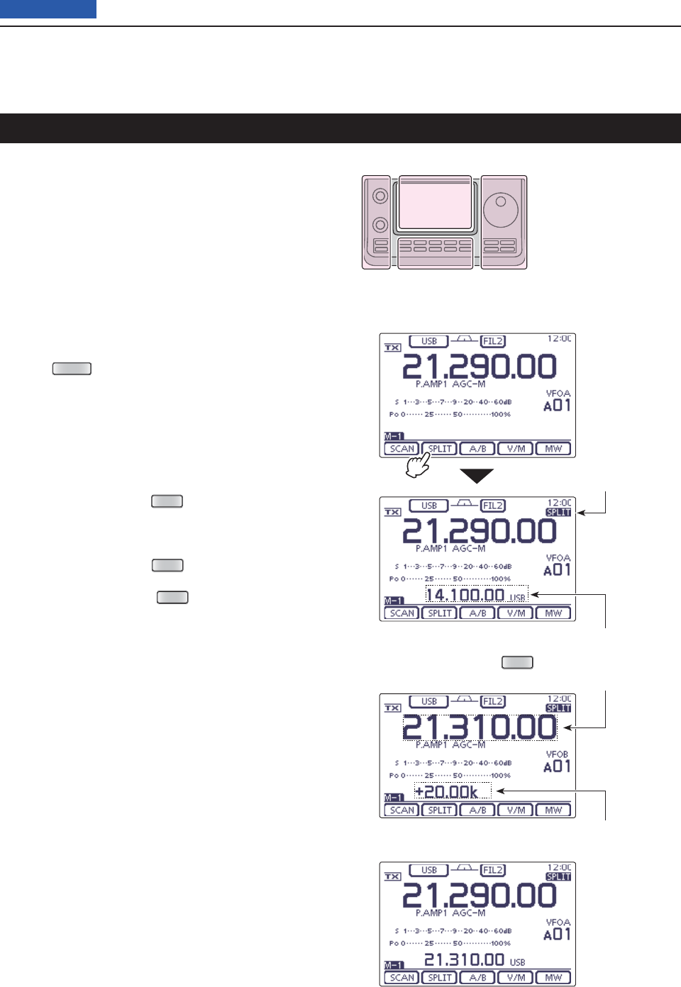
6FUNCTIONS FOR TRANSMIT
6-8
Previous view
The L, R, C or D in the
instructions indicate the
part of the controller.
L: Left side
R: Right side
C: Center bottom
D: Display (Touch panel)
Left Right
Center
Display
Split frequency operation
Split frequency operation allows you to transmit and
receive on two different frequencies. Split frequency
operation is performed using frequencies in VFO A and
VFO B.
• The Split frequency operation is automatically turned OFF
when turning ON the One-touch repeater function.
The following is an example of setting 21.290 MHz/
USB mode for receiving and 21.310 MHz/USB mode
for transmitting.
Set 21.290 MHz in VFO A and select the USB q
mode.
Push w
MENU
(C) one or more times to select the
“M-1” screen (M-1 menu).
Touch [SPLIT]( eD)
to turn ON the
Split function
.
• The transmit frequency (VFO B) and “SPLIT” appear.
• If desired, tap [SPLIT](D) again to turn OFF the func-
tion.
Set 21.310 MHz in VFO B and select the USB mode. r
The setting method has the three following ways.
(1) While holding down
XFC
(R) in VFO A, rotate the
Dial to set the transmit frequency to 21.310 MHz
in VFO B, and then select the operating mode to
USB.
• While holding down
XFC
(R), you can change the
frequency band and operating mode in VFO B.
• While holding down
XFC
(R), the transceiver re-
ceives the transmit frequency in VFO B.
(2) Touch [A/B](D) to select VFO B, rotate the Dial
to set the transmit frequency to 21.310 MHz, and
then select the operating mode to USB.
(3) Use the Quick Split function.
• The Quick Split function is much more convenient for
selecting the transmit frequency. See the next content
for details.
t Now you can receive on 21.290 MHz and transmit on
21.310 MHz.
To change the transmit and receive frequencies, push
[A/B] to exchange VFO A and VFO B.
• While holding down
XFC
• After setting up
Split icon
Touch [SPLIT]
Shows the transmit frequency (VFO B)
Shows the transmit frequency (VFO B)
Shows the frequency shift and direction
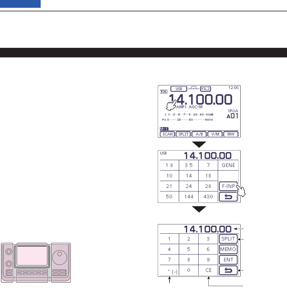
6FUNCTIONS FOR TRANSMIT
6-9
Previous view
Split frequency operation (Continued)
Direct frequency shift input D
The frequency shift can directly be entered.
Touch the MHz digits to enter the Band selection dis- q
play.
Touch [F-INP]( wD) to enter the Direct input screen.
If the Shift direction is minus, touch “• (–).” e
• [SPLIT] changes to [–SPLIT], and displays the Minus set-
ting mode.
Touch the desired number to enter the desired fre- r
quency shift.
• –9.999 to +9.999 MHz can be set in 1 kHz steps.
Touch [SPLIT] or [–SPLIT]( tD) to input the frequency
shift to the transmit frequency, and the Split function
is turned ON.
[Example]
To transmit on a 10 kHz higher frequency:
Touch [1], [0] then [SPLIT]. ➥
To transmit on 1.025 MHz lower frequency:
Touch [• (–)], [1], [0], [2], [5] then [–SPLIT]. ➥
The L, R, C or D in the
instructions indicate the
part of the controller.
L: Left side
R: Right side
C: Center bottom
D: Display (Touch panel)
Left Right
Center
Display
• Direct input screen
Minus (–) input Delete entering
Enter the Split off-
set
Cancel edit
Shows the input
digits
Touch the MHz
digits.
Touch [F-INP]
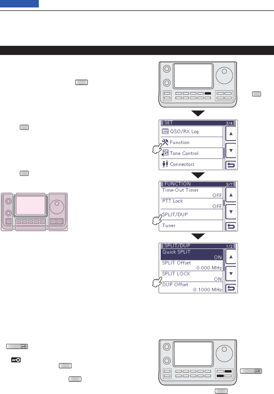
6FUNCTIONS FOR TRANSMIT
6-10
Previous view
Split frequency operation (Continued)
Split Lock function D
The Split Lock function is convenient for changing only
the transmit frequency. When the Split Lock function is
not used, accidentally releasing
XFC
(R)
while rotating
the Dial, changes the receive frequency.
The Split Lock function is OFF by default, but can be
turned ON
in the
“SPLIT LOCK” item of the
“Function”
Set mode. (p. 165)
• Setting
Push q
SET
(C) to enter the Set mode.
Touch the “SPLIT LOCK” item of the “Function” Set w
mode.
Function > SPLIT/DUP > SPLIT LOCK
• If the specifi ed item is not displayed, touch [Y] or [Z](D)
one or more times to select the page.
Touch the option to turn ON the function. e
Push r
SET
(C) to exit the Set mode.
• Operation
While Split frequency operation is ON, hold down q
SPEECH
(R) for 1 second to activate the split lock
function.
• “ ” appears.
While holding down w
XFC
(R), rotate the Dial to
change the transmit frequency.
• If you accidentally release
XFC
(R) while rotating the
Dial, the receive frequency does NOT change.
SPEECH
XFC
The L, R, C or D in the
instructions indicate the
part of the controller.
L: Left side
R: Right side
C: Center bottom
D: Display (Touch panel)
Left Right
Center
Display
Touch
“Function”
Touch
“SPLIT/DUP”
Touch
“SPLIT LOCK”
Push
SET
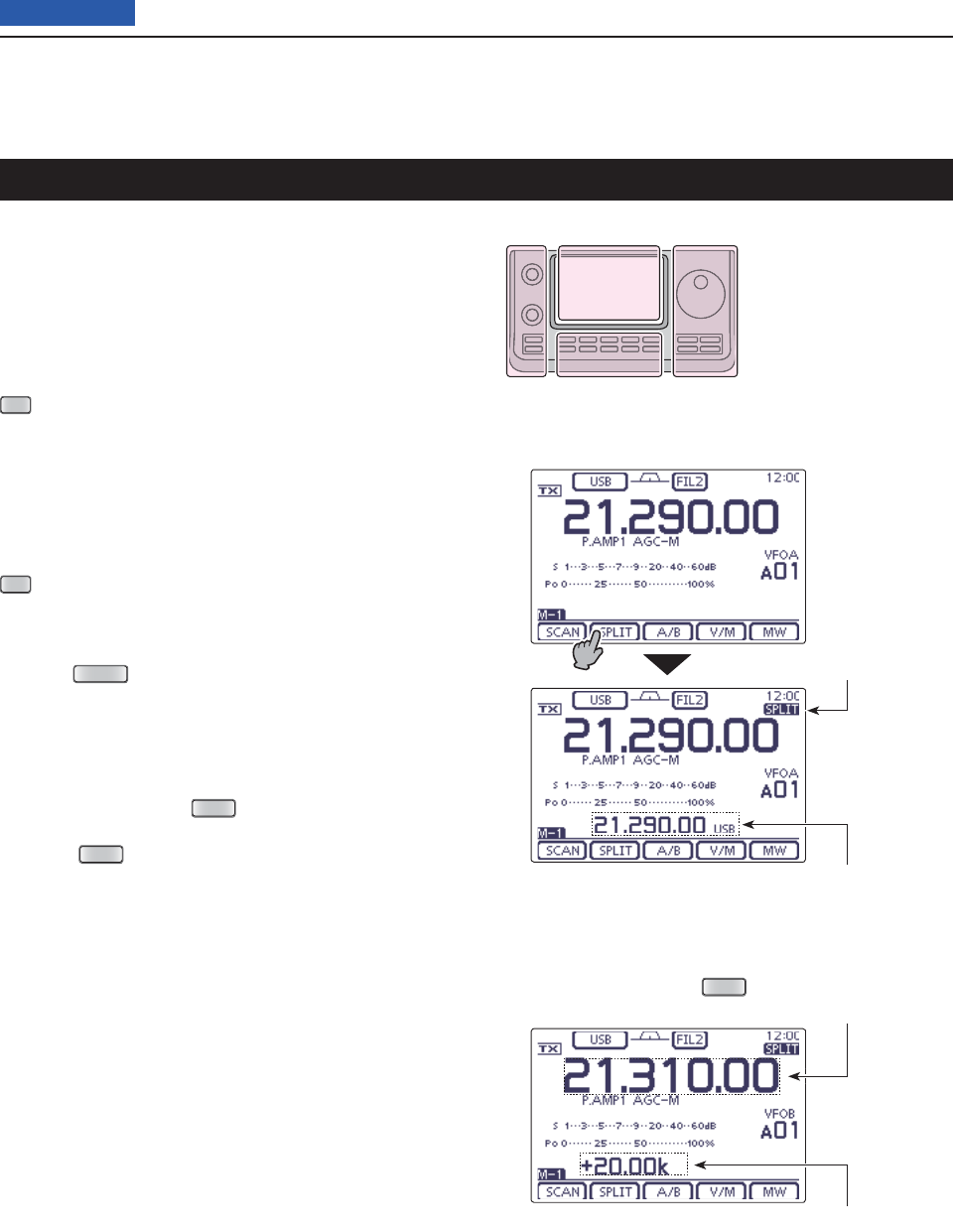
6FUNCTIONS FOR TRANSMIT
6-11
Previous view
Quick Split function
When you touch [SPLIT](D) for 1 second, the Split fre-
quency operation is turned ON. The undisplayed VFO
is automatically changed according to the plus/minus
frequency shift programmed in the “SPLIT Offset” item
of the “Function” Set mode (p. 165). Or the VFOs are
equalized when 0.000 MHz (default setting) is pro-
grammed as the Split Offset (p. 165).
SET
(C) > Function > SPLIT/DUP > SPLIT Offset
The Quick Split function is ON by default. For your con-
venience, it can be turned OFF in the
“Quick SPLIT”
item of the
“Function” Set mode (p. 165). In this case,
touch [SPLIT](D) for 1 second does not equalize the
VFO A and VFO B frequencies.
SET
(C) > Function > SPLIT/DUP > Quick SPLIT
Suppose you are operating at 21.290 MHz (USB) in q
VFO A.
Push w
MENU
(C) one or more times to select the
“M-1” screen (M-1 menu).
Touch [SPLIT]( eD) for 1 second
.
• Split frequency operation is turned ON.
• The transmit (VFO B) frequency is equalized to the re-
ceive (VFO A) frequency.
While holding down r
XFC
(R), rotate the Dial to set
the frequency offset between transmit and receive.
• When
XFC
(R) is released, the receive frequency is dis-
played.
The L, R, C or D in the
instructions indicate the
part of the controller.
L: Left side
R: Right side
C: Center bottom
D: Display (Touch panel)
Left Right
Center
Display
The example shows the split offset
is set to +20 kHz (+0.020 MHz).
• While holding down
XFC
Split icon
Shows the transmit frequency (VFO B)
Shows the transmit frequency (VFO B)
Shows the frequency shift and direction
Touch [SPLIT]
for 1 second
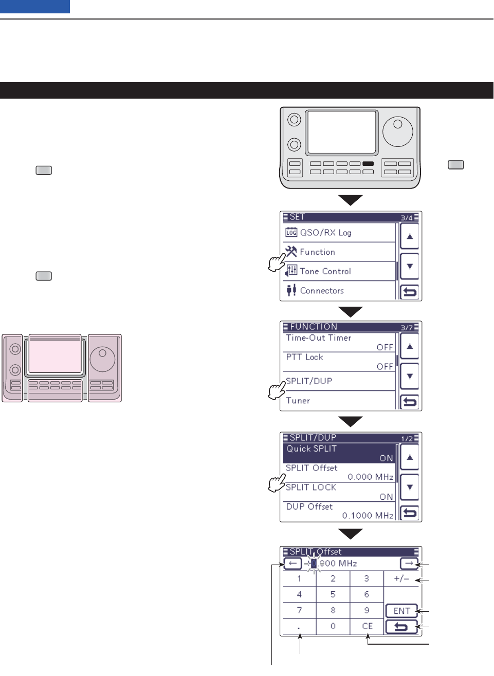
6FUNCTIONS FOR TRANSMIT
6-12
Previous view
Quick Split function (Continued)
Split frequency offset setting D
By setting an often-used split frequency offset in ad-
vance, you can use the Quick Split function to select split
operation at the touch of one key.
Push q
SET
(C) to enter the Set mode.
Touch the “SPLIT Offset” item of the “Function” Set w
mode.
Function > SPLIT/DUP > SPLIT Offset
• If the specifi ed item is not displayed, touch [Y] or [Z](D)
one or more times to select the page.
Touch the number to enter the desired frequency e
shift, and then touch [ENT](D).
• –9.999 to +9.999 MHz can be set in 1 kHz steps.
Push r
SET
(C) to exit the Set mode.
The L, R, C or D in the
instructions indicate the
part of the controller.
L: Left side
R: Right side
C: Center bottom
D: Display (Touch panel)
Left Right
Center
Display
Touch
“Function”
Touch
“SPLIT/DUP”
Touch
“SPLIT Offset”
Push
SET
Enter the decimal point
Move the cursor
Move the cursor
Select a direc-
tion
Enter
Cancel edit
Delete entering
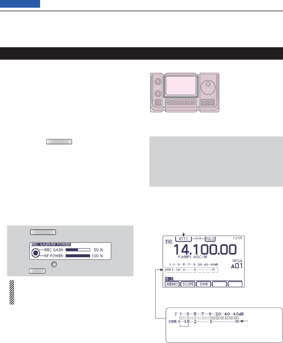
6FUNCTIONS FOR TRANSMIT
6-13
Previous view
Measuring SWR
The IC-7100 has a built-in circuit for measuring antenna
SWR— no external equipment or special adjustments
are necessary.
The IC-7100 can measure SWR two ways— spot mea-
surement and plot measurement.
Spot measurement D
This function is convenient to use when measuring
SWR of the antenna to install or periodic check.
q If desired, push
TUNER/CALL
(L) once or twice to turn
OFF the antenna tuner.
• If the antenna tuner is connected, and your want to mea-
sure SWR of the antenna itself, perform this step.
Select the desired frequency band. (p. 3-5) w
On the Mode selection screen, select the RTTY or e
RTTY-R mode. (p.3-??)
If necessary, adjust the RF power to more than 30 W r
on the Mic gain/RF power adjustment display.
• If your are operating in the 144 MHz band, adjust the RF
power to more than 20 W.
• If your are operating in the 430 MHz band, adjust the RF
power to more than 15 W.
q Push
MIC/RF PWR
(C) to open the MIC gain/RF
power adjustment display.
w Rotate [BANK] (L) to adjust the RF power.
e Push
MENU
(C) to close the display.
Before transmitting, monitor the operating fre-
quency to make sure transmitting won’t cause
interference to other stations on the same fre-
quency.
Touch the TX meter one or more times to select the t
SWR meter.
Hold down [PTT] on the microphone or switch ON y
the external TX switch to transmit.
Read the SWR on the SWR meter. u
• If the SWR meter points 1.5 or less, the antenna is
matched .
Release [PTT] or Switch OFF the external TX switch i
to receive.
• When the measured SWR is more than 1.5:1, adjust the
antenna to match with the transceiver.
The L, R, C or D in the
instructions indicate the
part of the controller.
L: Left side
R: Right side
C: Center bottom
D: Display (Touch panel)
Left Right
Center
Display
NOTE
This transceiver can measure SWR in the 144 MHz or
430 MHz bands.
Depending on the length of the connected coaxial
cable, or installation condition, the measurement may
be different from the actual SWR of the antenna in
these band.
The best match is in this range.
(1.5 or less)
SWR meter
RTTY mode icon
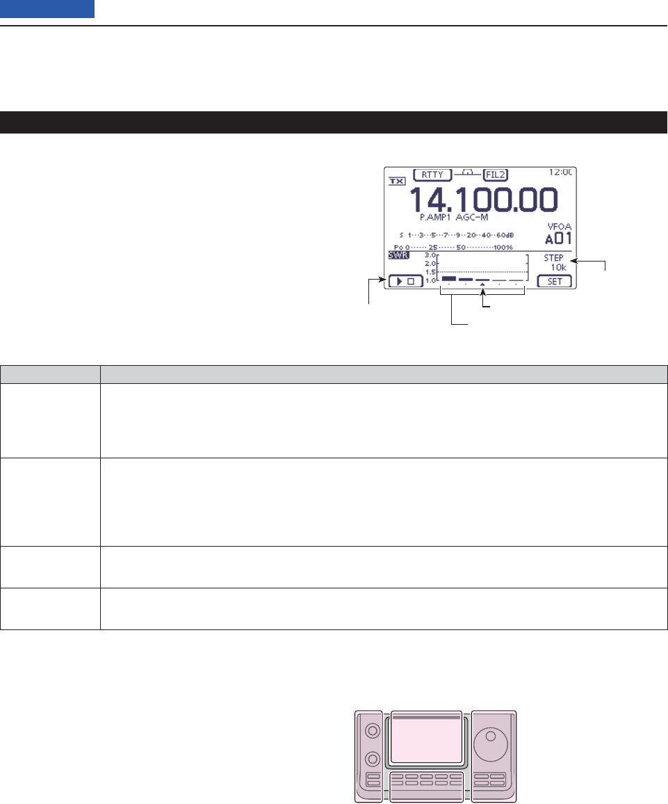
6FUNCTIONS FOR TRANSMIT
6-14
Previous view
Plot measurement D
Plot measurement allows you to measure the SWR
over an entire band.
Measuring SWR (Continued)
INDICATOR DESCRIPTION
Measurement
start icon
Touch [](D) to start the measuring. While measuring, “” is displayed. The measured fre-
quency is displayed by the frequency display mark, “∫,” below the graph bar. While measuring
SWR, the frequency cannot be changed. When quieting the SWR measurement, the frequency
returns to the previous frequency before starting the SWR measurement.
Graph bar
display
Each vertical dot indicates the SWR value, and horizontal bar indicates the number of measure-
ment steps. The measurement steps can be selected the “Number of Graph Bar” item of the
“SWR GRAPH SET” screen.
SWR graph displays SWR 1 to 3 vertically, and many dots indicates the worse SWR.
(SWR is displayed 1.0=1 dot, 1.5=10 dots, 2.0=19 dots and 3.0=28 dots.)
Frequency
display mark Displays the relative position of the measurement frequency.
SWR measur-
ing step
Displays the selected SWR measuring step.
Set the “Measuring Step” item of the “SWR GRAPH SET” screen.
The L, R, C or D in the
instructions indicate the
part of the controller.
L: Left side
R: Right side
C: Center bottom
D: Display (Touch panel)
Left Right
Center
Display
SWR measuring
step
Shows starting
measurement Shows the graph bar
Frequency display mark
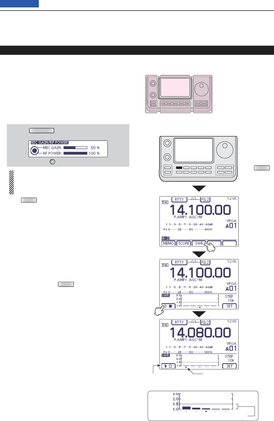
6FUNCTIONS FOR TRANSMIT
6-15
Previous view
Measuring SWR
Plot measurement (Continued) D
Select the desired frequency band. (p. 3-5) q
On the Mode selection screen, select the RTTY or w
RTTY-R mode. (p.3-??)
If necessary, adjust the RF power to more than 30 W e
on the Mic gain/RF power adjustment display.
• If your are operating in the 144 MHz band, adjust the RF
power to more than 20 W.
• If your are operating in the 430 MHz band, adjust the RF
power to more than 15 W.
q Push
MIC/RF PWR
(C) to open the MIC gain/RF
power adjustment display.
w Rotate [BANK] (L) to adjust the RF power.
Before transmitting, monitor the operating fre-
quency to make sure transmitting won’t cause
interference to other stations on the same fre-
quency.
Push r
MENU
(C) one or more times to select the
“M-3” screen (M-3 menu).
Touch [SWR]( tD) to display the “SWR” (SWR Graph)
screen.
Set the center frequency for the SWR to be mea- y
sured.
If necessary, touch [SET]( uD) to enter the “SWR
GRAPH SET” screen to set the Number of graph bar
or Measuring step.
• The selectable number of graph bar are 3, 5, 7, 9, 11 and
13.
• The selectable measuring steps are 10k, 50k, 100k and
500 kHz.
• Touch [](D) or push
MENU
(C) to return to the previ-
ous screen.
Touch [ i](D) to start the measuring.
• A frequency marker, “∫,” appears below the left edge of
the graph bars and displays the frequency.
Hold down [PTT] on the microphone or switch ON o
the external TX switch to transmit.
• The bar graph displays the SWR.
!0 Release [PTT] or Switch OFF the external TX switch
to receive.
• The frequency marker moves to, and frequency display
changes to the next frequency to be measured.
!1 Repeat steps o and !0 to measure SWR over the
entire frequency range.
The L, R, C or D in the
instructions indicate the
part of the controller.
L: Left side
R: Right side
C: Center bottom
D: Display (Touch panel)
Left Right
Center
Display
Touch [SWR]
Touch []
Measuring SWR
While measuring SWR, the frequency cannot be changed
Frequency display mark
The best match is in this range. (1.5 or less)
Push
MENU
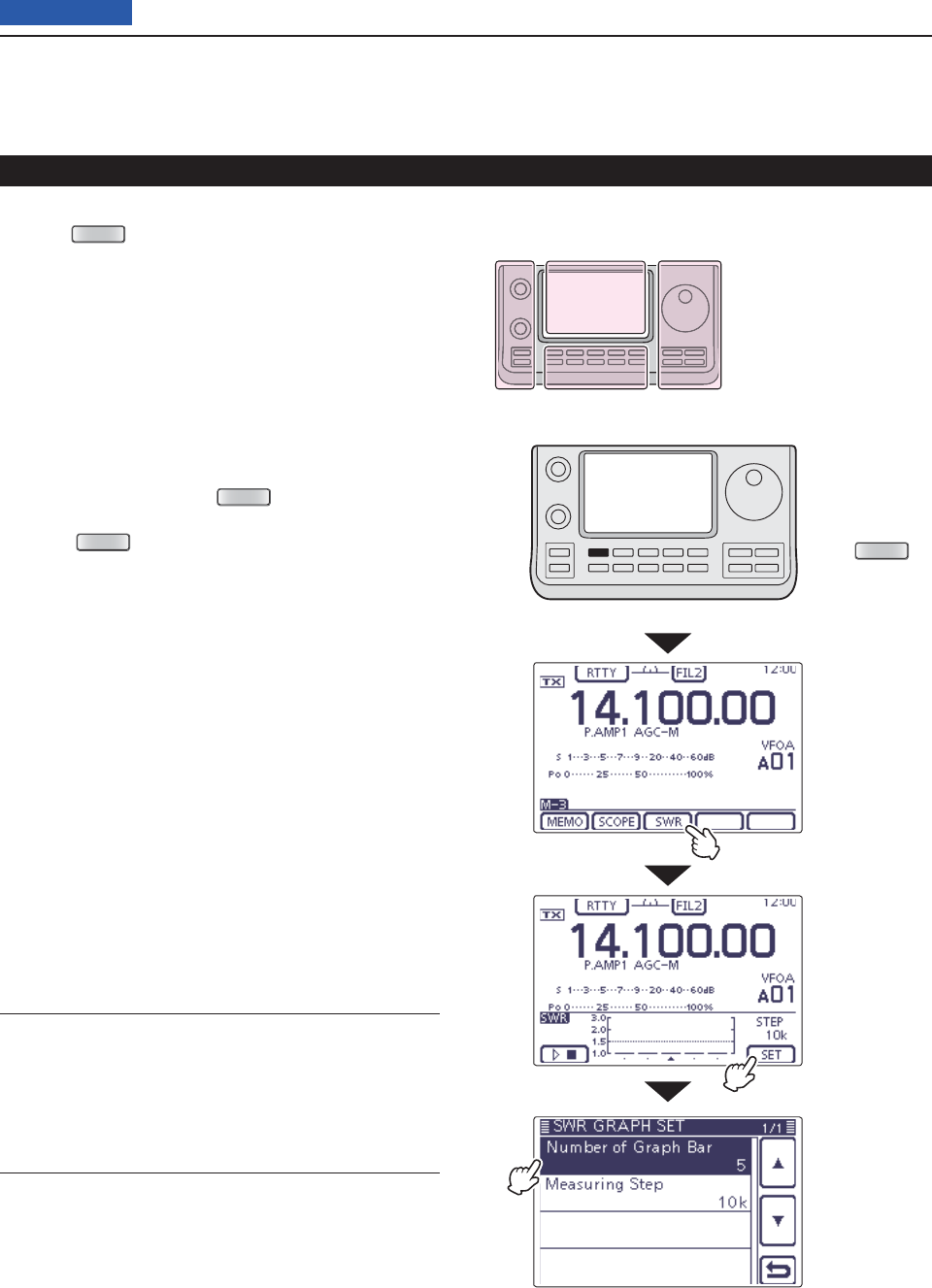
6FUNCTIONS FOR TRANSMIT
6-16
Previous view
SWR Graph Set mode D
Push q
MENU
(C) one or more times to select the
“M-3” screen (M-3 menu).
Touch [SWR]( wD) to display the “SWR” (SWR Graph)
screen.
Touch [SET]( eD) to enter the “SWR GRAPH SET”
screen.
Touch the desired item to select. r
• See below for details of the set items and options.
Touch the tdesired option to change the setting.
• If desired, touch the item for 1 second to open the De-
fault set window, then select the “Default” to reset to the
default setting.
Touch [ y](D) or push
MENU
(C) to return to the
“SWR” (SWR Graph) screen.
Push u
MENU
(C)
to return to the “M-3” screen
(Menu 3)
.
Measuring SWR (Continued)
Number of Graph Bar (Default: 5)
Select the number of the graph bar for the displayed
SWR Graph.
• The selectable number are 3, 5, 7, 9, 11 and 13.
Measuring Step (Default: 10k)
Select the SWR measuring step for the center frequen-
cy.
• The selectable steps are 10k, 50k, 100k and 500
kHz.
The L, R, C or D in the
instructions indicate the
part of the controller.
L: Left side
R: Right side
C: Center bottom
D: Display (Touch panel)
Left Right
Center
Display
Touch [SET]
Touch the item
Touch [SWR]
Push
MENU
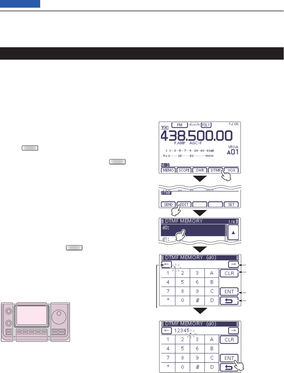
6FUNCTIONS FOR TRANSMIT
6-17
Previous view
DTMF Memory encoder
DTMF tones are used for autopatching, controlling oth-
er equipment, and so on. The transceiver has 16 DTMF
memory channels for storage of often-used DTMF
codes sequence of up to 24 digits.
Programming a DTMF code D
Select the desired frequency band. (p. 3-5) q
On the Mode selection screen, select the FM or DV w
mode. (p.3-??)
• The DTMF encoder can be used in the FM or DV mode.
Push e
MENU
(C) one or more times to select the
“M-3” screen (M-3 menu).
• If your are operating in the DR mode, push
MENU
(C)
once or twice to select the “D-2” screen (D-2 menu).
Touch [DTMF]( rD)
to display the DTMF mode.
• The “DTMF” screen is displayed.
Touch [EDIT]( tD) to display the “DTMF MEMORY”
screen.
Touch the desired channel to select. y
• “d0” to “d9,” “dA” to “dD,” “d½” and “d#” are selectable.
Touch the unumber or character to enter the desired
DTMF code.
After entering the DTMF codes, touch [ENT]( iD) to
save the channel, and return to the “DTMF MEMO-
RY” screen.
Touch [ o](D) or push
MENU
(C) to return to the
“DTMF” screen.
The L, R, C or D in the
instructions indicate the
part of the controller.
L: Left side
R: Right side
C: Center bottom
D: Display (Touch panel)
Left Right
Center
Display
Move the cursor
Move the cursor
Delete a number
Enter
Cancel edit
Touch [ENT]
Touch [EDIT]
Touch [DTMF]
Touch the channel
Example “d0”
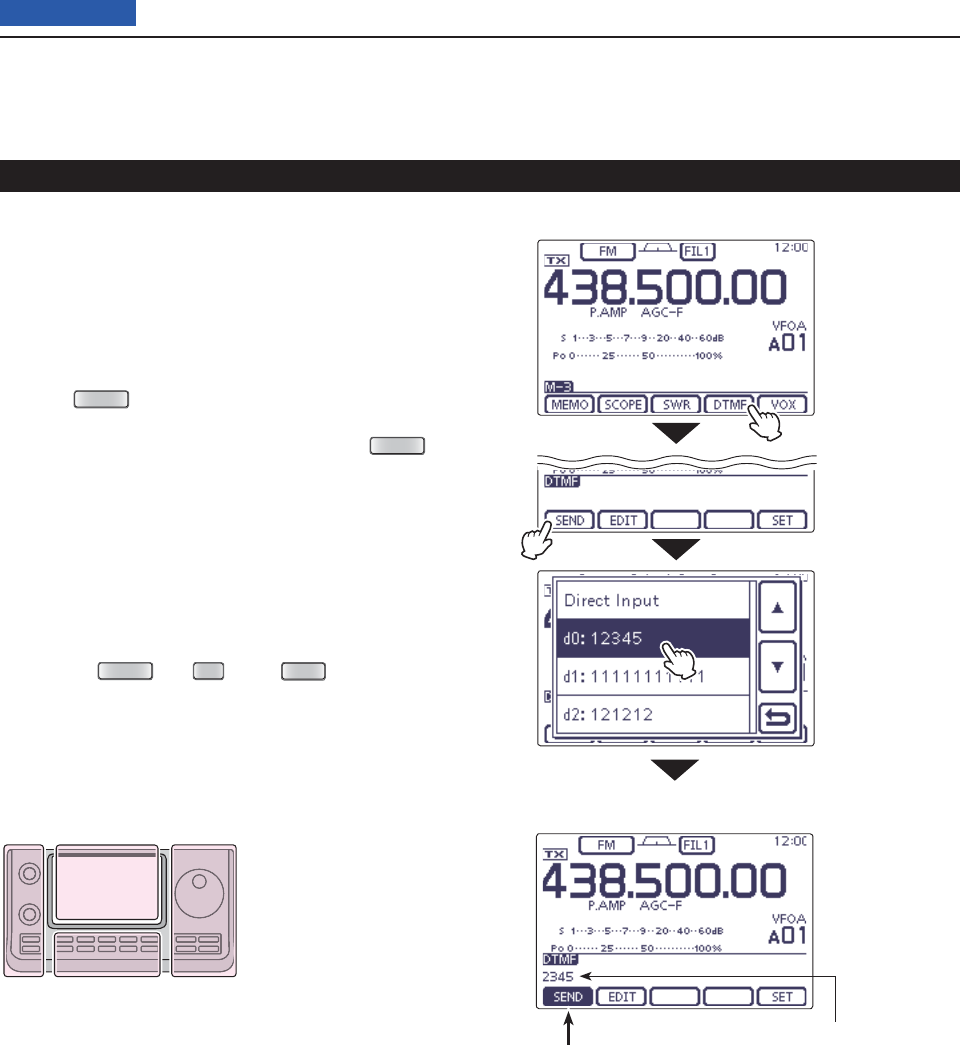
6FUNCTIONS FOR TRANSMIT
6-18
Previous view
Transmitting DTMF code D
To transmit DTMF code using a DTMF send window,
program the desired code in advance.
Select the desired frequency band. (p. 3-5) q
On the Mode selection screen, select the FM or DV w
mode. (p.3-??)
• The DTMF encoder can be used in the FM or DV mode.
Push e
MENU
(C) one or more times to select the
“M-3” screen (M-3 menu).
• If your are operating in the DR mode, push
MENU
(C)
once or twice to select the “D-2” screen (D-2 menu).
Touch [DTMF]( rD)
to display the DTMF mode.
• The “DTMF” screen is displayed.
Touch [SEND]( tD) to open the DTMF send window.
Touch the desired channel to transmit the DTMF y
code.
• The transceiver automatically transmits the selected
DTMF code.
• While transmitting, touch [SEND], [EDIT] or [SET](D)
or push
MENU
(C),
SET
(C) or
XFC
(R), cancels the
transmission.
• After transmitting, transceiver returns to the “DTMF”
screen.
DTMF memory encoder (Continued)
The L, R, C or D in the
instructions indicate the
part of the controller.
L: Left side
R: Right side
C: Center bottom
D: Display (Touch panel)
Left Right
Center
Display
Touch [SEND]
Touch [DTMF]
The DTMF code scrolls to the
left edge, and disappears every
one digit when the each digit is
sent.
Highlighted
while transmitting
Touch the DTMF
channel
Example: d0
• While transmitting
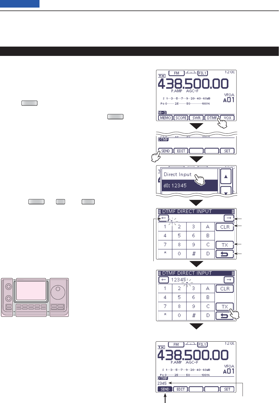
6FUNCTIONS FOR TRANSMIT
6-19
Previous view
Transmitting DTMF code (Direct Input) D
Select the desired frequency band. (p. 3-5) q
On the Mode selection screen, select the FM or DV w
mode. (p.3-??)
• The DTMF encoder can be used in the FM or DV mode.
Push e
MENU
(C) one or more times to select the
“M-3” screen (M-3 menu).
• If your are operating in the DR mode, push
MENU
(C)
once or twice to select the “D-2” screen (D-2 menu).
Touch [DTMF]( rD)
to display the DTMF mode.
• The “DTMF” screen is displayed.
Touch [SEND]( tD) to open the DTMF send window.
Touch “Direct Input” to display the “DTMF DIRECT y
INPUT” screen.
Touch the unumber or character to enter the desired
DTMF code.
When all digit are set, touch [TX]( iD) to transmit the
code.
• The transceiver automatically transmits the DTMF code.
• While transmitting, touch [SEND], [EDIT] or [SET](D)
or push
MENU
(C),
SET
(C) or
XFC
(R), cancels the
transmission.
• After transmitting, transceiver returns to the “DTMF”
screen.
DTMF memory encoder (Continued)
The DTMF code scrolls to the
left edge, and disappears every
one digit when the each digit is
sent.
Highlighted
while transmitting
• While transmitting
The L, R, C or D in the
instructions indicate the
part of the controller.
L: Left side
R: Right side
C: Center bottom
D: Display (Touch panel)
Left Right
Center
Display
Move the cursor
Move the cursor
Delete a number
Transmit the code
Cancel edit
Touch [TX]
Touch [SEND]
Touch [DTMF]
Touch
“Direct Input”
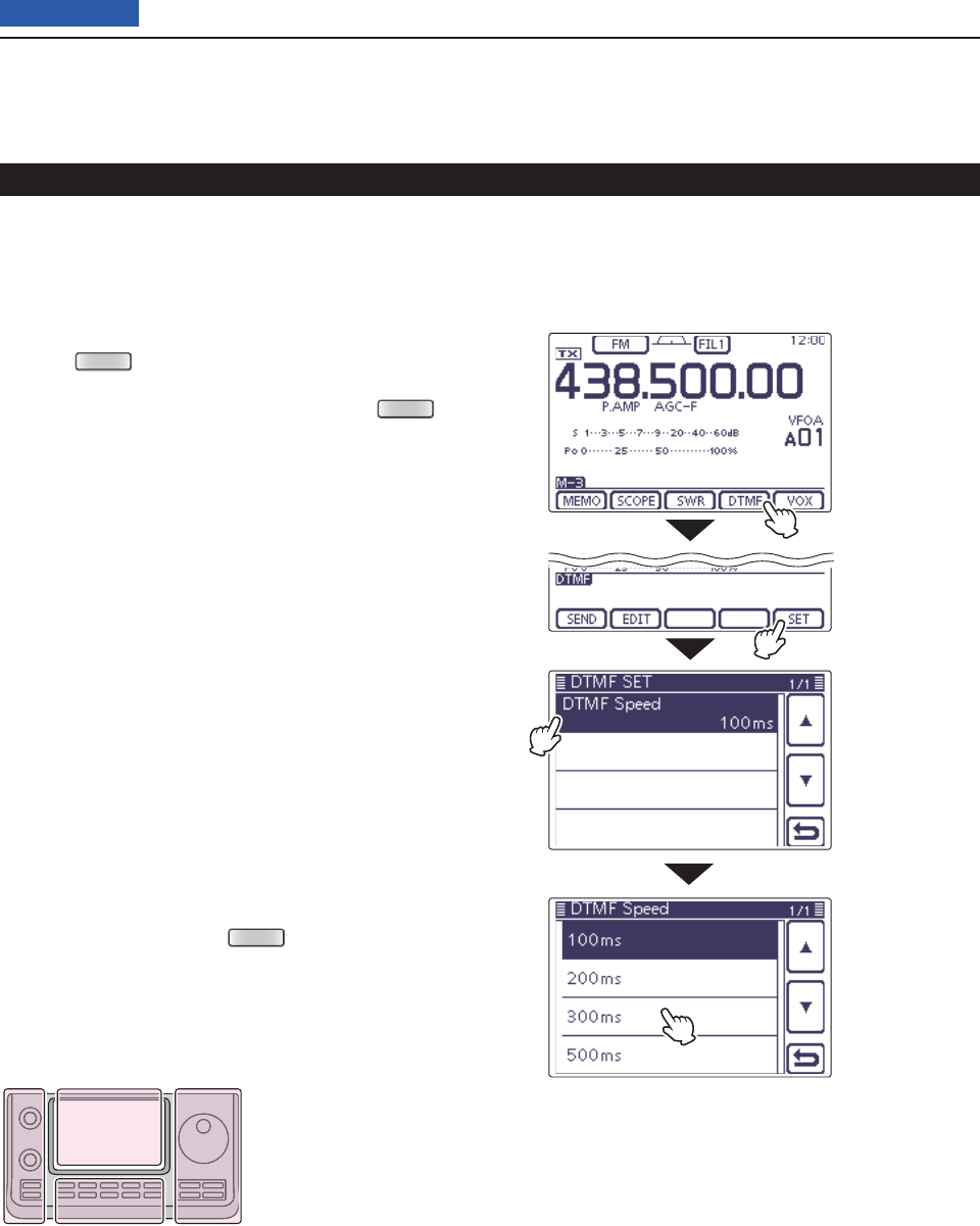
6FUNCTIONS FOR TRANSMIT
6-20
Previous view
Setting DTMF transfer speed D
The DTMF transfer speed can be selected.
On the Mode selection screen, select the FM or DV q
mode. (p.3-??)
• The DTMF encoder can be used in the FM or DV mode.
Push w
MENU
(C) one or more times to select the
“M-3” screen (M-3 menu).
• If your are operating in the DR mode, push
MENU
(C)
once or twice to select the “D-2” screen (D-2 menu).
Touch [DTMF]( eD)
to display the DTMF mode.
• The “DTMF” screen is displayed.
Touch [SET]( rD) to enter the “DTMF SET” mode.
Touch “DTMF Speed” to enter the “DTMF Speed” set t
screen.
Touch the desired option to change the setting. y
• 100ms: Transfer the DTMF tones at about 100 millisec-
onds per code.
5 characters per second.
• 200ms: Transfer the DTMF tones at about 200 millisec-
onds per code.
2.5 characters per second.
• 300ms: Transfer the DTMF tones at about 300 millisec-
onds per code.
1.6 characters per second.
• 500ms: Transfer the DTMF tones at about 500 millisec-
onds per code.
1 character per second.
• If desired, touch the item for 1 second to open the Default
set window, then select the “Default” to reset to the de-
fault setting.
Touch [ u](D) or push
MENU
(C) to return to the
“DTMF” screen.
DTMF memory encoder (Continued)
The L, R, C or D in the
instructions indicate the
part of the controller.
L: Left side
R: Right side
C: Center bottom
D: Display (Touch panel)
Left Right
Center
Display
Touch [SET]
Touch [DTMF]
Touch the item
Touch the option
Example: 300 ms
Example: Set the DTMF transfer speed to 300 millisec-
onds.

7-1
Section 7D-STAR INTRODUCTION
Previous view
IMPORTANT!
• The repeater list, described in this manual, may differ from your transceiver’s preloaded contents.
• Although Japanese repeaters are used in the setting examples, the Japanese repeater node (port) letters are dif-
ferent from other country’s.
Be sure to add a repeater node letter as the 8th digit in the call sign fi eld after a repeater call sign, according to
the repeater frequency band, as shown below.
1200 MHz: A (B in Japan)
430 MHz: B (A in Japan)
144 MHz: C (no D-STAR repeaters in Japan)
“MY” (Your own call sign) programming .............................7-2
D-STAR Intoroduction ...........................................................7-5
About the DR (D-STAR Repeater) mode ..............................7-6
Communication Form in the DR mode ................................7-7
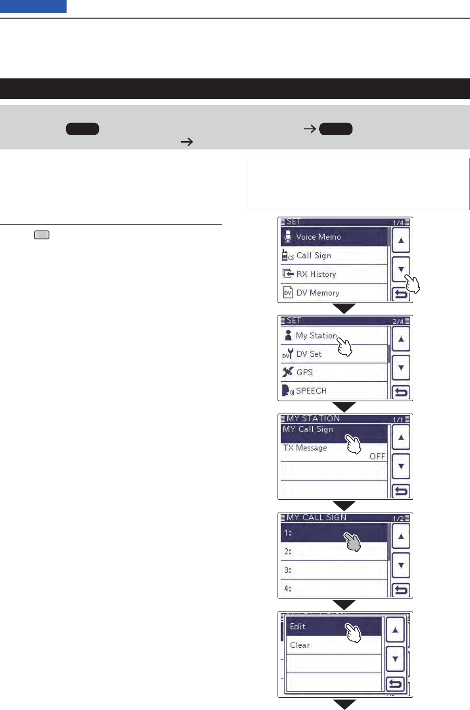
7D-STAR INTRODUCTION
7-2
Previous view
IMPORTANT!
Before starting D-STAR, the following steps are needed.
STEP 1 Entering your call sign (MY) into the transceiver. STEP 2 Registering your call sign
(MY) to a gateway repeater. You have completed the steps!!
“MY” (Your own call sign) programming
You can store up to 6 “MY” call signs.
Example: Enter “JA3YUA” as your own call sign into the
MY call sign memory [MY1].
Display the My Call Sign Edit screen1.
Push q
SET
(C) to enter the Set mode.
Touch the “MY Call Sign” item of the “My Station” Set w
mode.
(My Station > MY Call Sign)
• If the specifi ed item is not displayed, touch [∫] or [√](D)
one or more times to select the page.
Touch the desired call sign memory for 1 second. e
(Example: 1:)
Touch the “Edit” item. r
• “MY CALL SIGN (MYM)” screen appears.
The memory number, selected in the step e, is dis-
played.
(Example: MY1)
The L, R, C or D in the instructions indicate the part of
the controller.
L: Left side, R: Right side, C: Center bottom
D: Display (Touch panel)
Continued on the next page ☞
Touch [√]
Touch
“My Station”
Touch
“MY Call Sign”
Touch the call
sign memory
for 1 second
(Example: 1:)
Touch
“Edit”
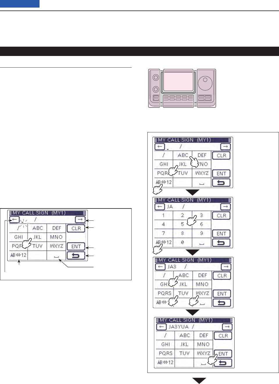
7D-STAR INTRODUCTION
7-3
Previous view
Enter the Call Sign2.
Touch the desired block one or more times to select t
the desired character or symbol.
(Example: J)
• A to Z, 0 to 9 and / are selectable.
• Touch “AB12” to toggle between the Alphabet input
and Number input mode.
• Touch [CLR](D) to delete the selected character, symbol
or number.
• Touch “” to input a space.
Touch [ y](D) to move the cursor backwards, or
touch [](D) to move the cursor forwards.
Repeat steps ut and y to enter your own call sign of
up to 8 characters, including spaces.
(Example: First J, then A, then 3, then Y, then U, then A)
Touch [ENT]( iD) to return to the “MY CALL SIGN”
screen.
“MY” (Your own call sign) programming (Continued)
Call sign edit screen
Input a space
Move the cursor
Move the cursor
Delete a character
Select an input mode
Enter
Cancel edit
Number input mode is selected.
Alphabet input mode is selected.
Enter “JA3YUA” into [MY1].
q Touch [JKL]
to enter ‘J.’
w Touch [ABC]
to enter ‘A.’
e Touch
[AB12].
o Touch [ENT]
q
yu
i
r
e
t
w
The L, R, C or D in the
instructions indicate the
part of the controller.
L: Left side
R: Right side
C: Center bottom
D: Display (Touch panel)
Left Right
Center
Display
Continued on the next page ☞
r Touch [3]
to enter ‘3.’
t Touch
[AB12].
y Touch [WXYZ]
three times
to enter ‘Y.’
u Touch [TUV]
two times
to enter ‘U.’
i Touch [ABC]
to enter ‘A.’
o
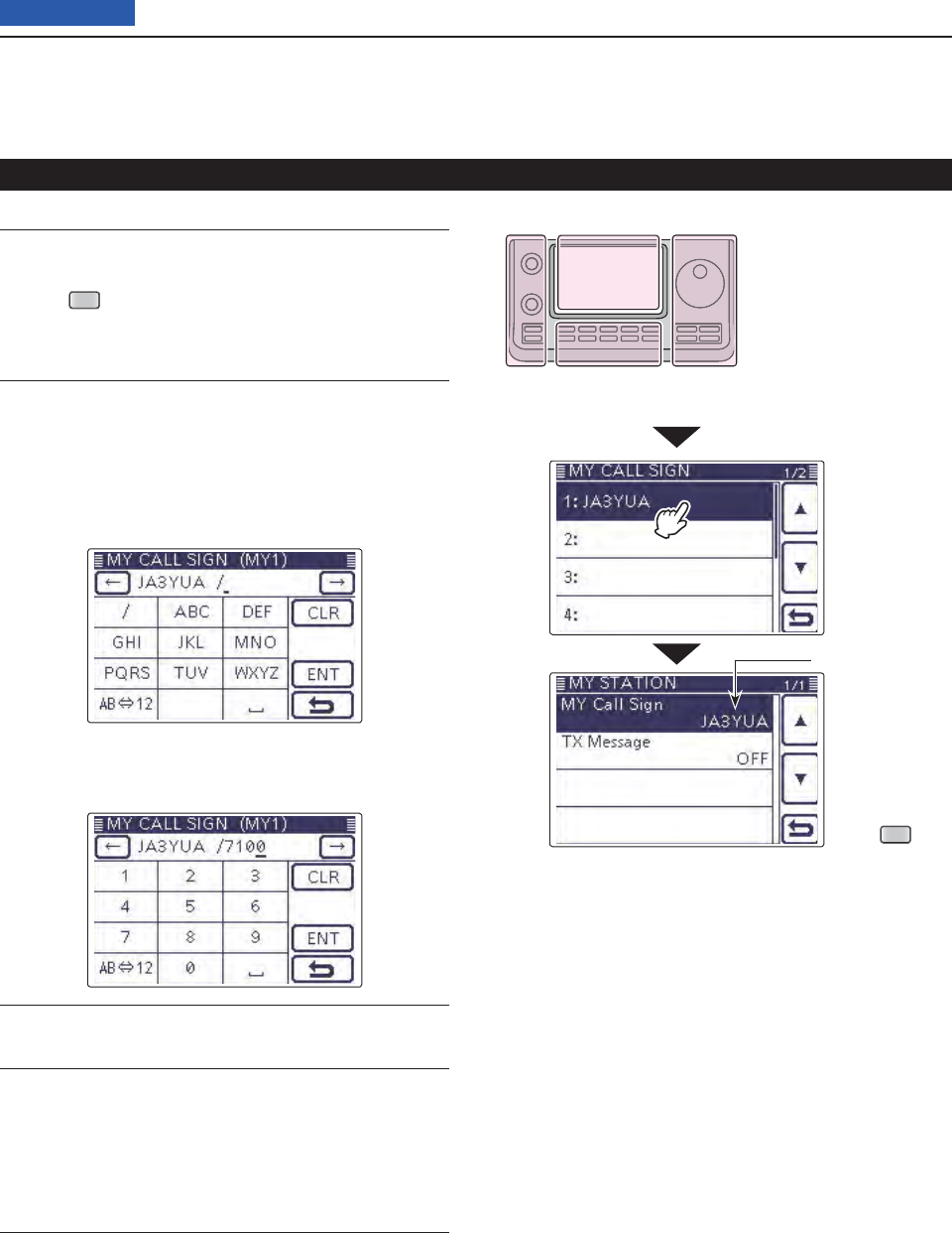
7D-STAR INTRODUCTION
7-4
Previous view
“MY” (Your own call sign) programming
Convenient! ✓
If necessary, enter a note of up to 4 characters, such as
the model of the transceiver, name, area name, and so
on, after your call sign.
Touch [ q](D) one or more times until the cursor
moves to the right of the “/”.
Repeat steps wt and y on the page 7-3 to enter a
desired 4 character note.
(Example: 7100)
Touch
SET
Appears
Touch the entered call sign to set the call sign to be o
used.
!0 Push
SET
(C) to exit the Set mode.
2. Enter the Call Sign (Continued) The L, R, C or D in the
instructions indicate the
part of the controller.
L: Left side
R: Right side
C: Center bottom
D: Display (Touch panel)
Left Right
Center
Display
Important! ✓
To use a repeater gateway, you must register your call
sign with a gateway repeater, usually one near your
home location.
If needed, ask the gateway repeater administrator for
call sign registration instructions.
Touch the
call sign
( Example:
1:JA3YUA)

7D-STAR INTRODUCTION
7-5
Previous view
• In the original D-STAR (Digital Smart Technologies for
Amateur Radio) plan, JARL envisioned a system of
repeaters grouped together into Zones.
• The D-STAR repeater enables you to call a HAM sta-
tion in another area through the internet.
• The transceiver can be operated in the digital voice
mode, including low-speed data operation, for both
transmit and receive. It has a built-in GPS receiver to
transmit and receive position data.
D-STAR Intoroduction
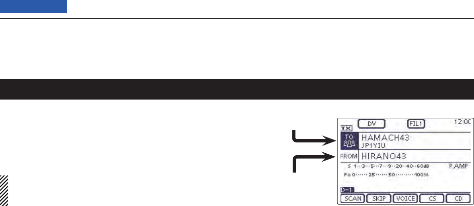
7D-STAR INTRODUCTION
7-6
Previous view
The DR (D-STAR Repeater) mode is one mode you can
use for D-STAR repeater operation. In this mode, you
can select the preprogrammed repeater or frequency in
“FROM” (the access repeater or simplex), and UR call
sign in “TO” (destination), as shown to the right.
NOTE: If the repeater, set to “FROM” (Access Re-
peater) has no Gateway call sign, you cannot make
a gateway call.
Destination
(Repeater/Station)
Access repeater
or Simplex
In the DR mode
About the DR (D-STAR Repeater) mode
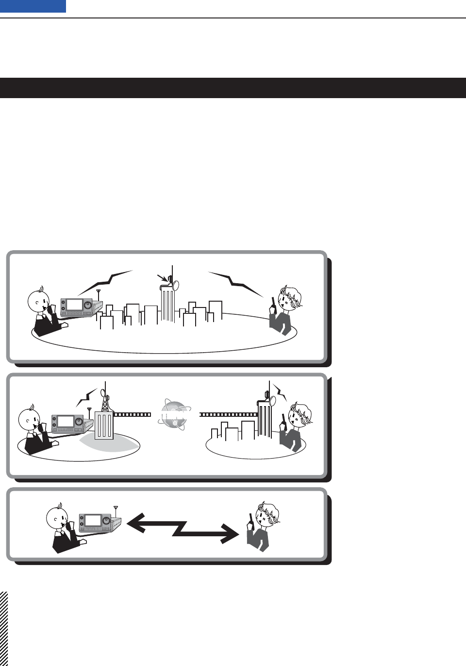
7D-STAR INTRODUCTION
7-7
Previous view
In the DR mode, the transceiver has three communica-
tion forms, as shown below.
• Local area call: To call through your local area (ac-
cess) repeater.
• Gateway call: To call through your local area (ac-
cess) repeater, repeater gateway and
the internet to your destination re-
peater or individual station’s last used
repeater, using call sign routing.
• Simplex call: To call another station not using a re-
peater.
NOTE:
• Programming the repeater list is required for DR mode operation. (pp. ??-?? to ??-??)
• Before operating in the DV mode, be sure to check whether the repeater is busy, or not. If the repeater is busy,
wait until it is clear, or ask for a “break” using a method acceptable to your local procedures.
• The transceiver has a Time-Out Timer function for digital repeater operation. The timer limits a continuous trans-
mission to approximately 10 minutes. Warning beeps will sound approximately 30 seconds before time-out and
then again immediately before time-out.
Communication Form in the DR mode
INTERNET
Local area call
Access repeater
Hamacho
repeater
Hamacho area
Gateway call Hirano
repeater
Hirano area
Sapporo
repeater
Sapporo area
Simplex call

11-1
Section 11 MEMORY OPERATION
Previous view
11-1
General description ...............................................................11-2
Memory channel contents
D .....................................................11-2
Selecting a Memory channel ................................................11-3
Selecting in the VFO mode
D ...................................................11-3
Selecting in the Memory mode
D ..............................................11-3
Selecting a Call channel .......................................................11-4
Programming a Memory channel ........................................11-5
Programming in the VFO mode
D .............................................11-5
Programming in the Memory mode
D .......................................11-5
Programming the Call channels
D ............................................11-5
Clearing a Memory channel ..................................................11-7
Copying Memory contents ...................................................11-8
Copying in the Memory mode
D ...............................................11-8
Copy
Ding in the VFO mode .....................................................11-8
Programming a Memory name ............................................11-9
Selecting a Memory display type .........................................11-11
Memo pad function ................................................................11-12
Writing the displayed contents into the Memo pads
D ..............11-12
Calling up the
DMemo pads.....................................................11-13
11 MEMORY OPERATION
11-2
Previous view
The transceiver has a total of 495 Memory channels (99
channels in each of 5 memory banks, A to E), 6 Scan
Edge channels (3 pairs) and two Call channels (C1/C2)
each for the 144 and 430 MHz frequency bands.
The Memory mode is useful to quickly select often-
used frequencies.
While in the memory mode, all 503 Memory channels
are tunable, which means the programmed frequency
can be temporarily tuned with the Dial.
When you tune a Memory channel without storing, and
then go back to the channel again, the original stored
frequency is displayed.
In the Memory mode, touch just above MHz area on
the display, and then select the desired band. Then ro-
tate the Dial to select the frequency to be stored.
Memory Channels Descriptions
1–99 (Total of 495) Regular Memory channels with split frequency capability.
1A/1B–3A/3B Program Scan Edge Memory channels with only simplex capability.
Stores the Scan Edge frequencies for programmed scans.
C1/C2 Two Call channels (C1/C2) each for the 144 and 430 MHz frequency bands.
Call channel with split frequency capability. Instantly recalls a specifi ed frequency.
Memory channel contents D
The following information can be programmed into
Memory channels:
• Operating frequency (p. ??-??)
• Operating mode (p. ??-??)
• IF fi lter number (p. ??-??)
• Split data (p. ??-??)
( Usable only on the regular Memory channels and
Call channels.)
• Memory name (p. ??-??)
• Duplex direction (DUP+ or DUP–) and frequency off-
set (pp. ??-??)
• Subaudible tone encoder (p. ??-??), tone squelch or
DTCS squelch ON/OFF (pp. ??-??, ??-??)
• Subaudible tone frequency (p. ??-??), tone squelch
frequency or DTCS code with polarity (p. ??-??)
• Destination call sign (p. ??-??)
• R1/R2 call signs (p. ??-??)
• Call sign squelch or Digital code squelch ON/OFF (p.
??-??)
• Digital code (p. ??-??)
NOTE:
Memory content can be erased by static electricity,
electric transients, and other causes. In addition, they
can be erased by a malfunction or during repairs.
Therefore, we recommend that you backup the mem-
ory content or save it to a SD card or to a PC.
• The SD card is not available from Icom. Purchase a
SD card to meet your needs.
• The optional CS-7100 CLONING SOFTWARE can also
be used to backup your memory data.
General description
The L, R, C or D in the
instructions indicate the
part of the controller.
L: Left side
R: Right side
C: Center bottom
D: Display (Touch panel)
Left Right
Center
Display
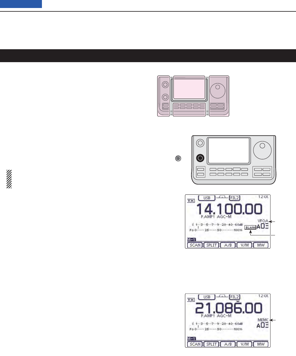
11 MEMORY OPERATION
11-3
Previous view
Selecting in the VFO mode D
Touch the Memory channel number indication once q
or twice to select the VFO mode. (p. ??-??)
Rotate [BANK]( wL) to select a Memory bank that
contains the channel you want to select.
Rotate [M-CH]( eL) to select a Memory channel num-
ber.
• Rotate clockwise to select a higher Memory channel
number; rotate counterclockwise to select a lower Mem-
ory channel number.
• All Memory channels, including blank channels, can be
selected.
• “BLANK” appears when no information has been pro-
grammed into the Memory channel. (Blank channel)
• You can do either step r or t fi rst.
NOTE: When the PBT indicator lights green, or
the RIT indicator lights orange, push [M-CH](L)
to turn OFF the indicator fi rst, and then rotate it.
Touch the Memory channel number indication to se- r
lect the Memory mode.
• “MEMO” and the Memory channel contents appear.
Selecting in the Memory mode D
Touch the Memory channel number indication once q
or twice to select the Memory mode. (p. ??-??)
Rotate [BANK]( wL) to select a Memory bank that
contains the channel you want to select.
Rotate [M-CH]( eL) to select a Memory channel num-
ber.
• Rotate clockwise to select a higher Memory channel
number; rotate counterclockwise to select a lower Mem-
ory channel number.
• All Memory channels, including blank channels, can be
selected.
• “BLANK” appears when no content has been programmed
into the Memory channel. (Blank channel)
• Memory channels can also be selected using the micro-
phone [UP]/[DN] keys. In such case, the blank channels
are skipped.
While in the VFO mode
While in the Memory mode
Appears
Appears
Appears
Outer: [BANK]
Inner: [M-CH]
Selecting a Memory channel
The L, R, C or D in the
instructions indicate the
part of the controller.
L: Left side
R: Right side
C: Center bottom
D: Display (Touch panel)
Left Right
Center
Display
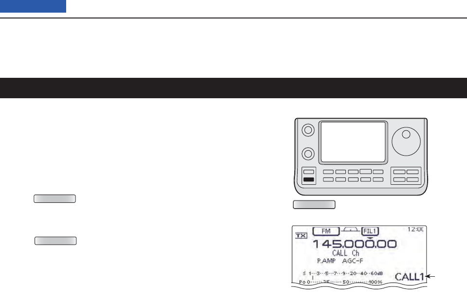
11 MEMORY OPERATION
11-4
Previous view
Two Call channels (C1/C2) are selectable in each of the
144 and 430 MHz frequency bands.
Factory default frequencies and operating modes are
programmed into the Call channels. Change these to
suit your operating needs. (see page ??)
Select qthe 144 or 430 MHz frequency band. (p. ??-
??)
Push w
TUNER/CALL
(L) to select the Call channel of the
selected frequency band.
• “CALL1” appears.
• Rotate [M-CH] to select “CALL2.”
Push e
TUNER/CALL
(L) again to return to the previous
screen display.
While in the Call channel mode
Appears
TUNER/CALL
Selecting a Call channel
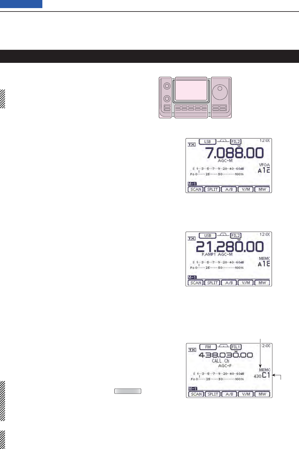
11 MEMORY OPERATION
11-5
Previous view
Memory channels can be programmed in either the
VFO mode or the Memory mode.
NOTE: If you perform the operations as described
below in a pre-programmed channel, the previous
channel content will be overwritten.
Programming in the VFO mode D
Touch the Memory channel number indication once q
or twice to select the VFO mode. (p. ??-??)
Set the desired contents into VFO A or VFO B. w
Rotate [BANK]( eL) or [M-CH](L) to select the Mem-
ory channel to be programmed.
• “BLANK” appears when no content has been programmed
into the Memory channel. (Blank channel)
Touch [MW]( rD) for 1 second to program the con-
tents into the Memory channel.
Programming in the Memory mode D
Touch the Memory channel number indication once q
or twice to select the Memory mode. (p. ??-??)
Rotate [M-CH]( wL) to select the Memory channel to
be programmed.
• The contents of the Memory channel appear in the dis-
play.
• “BLANK” appears if the selected Memory channel is a
blank channel.
Set the desired contents into the Memory channel. e
• When a blank channel is selected, touch just above MHz
area on the display, and then select the desired band.
Rotate the Dial to select the frequency. (p. ??)
Touch [MW]( rD) for 1 second to program the con-
tents into the Memory channel.
Programming the Call channels D
It is convenient to program often-used frequencies into
the Call channels for quick recall.
Rotate [M-CH]( qL) to select a Call channel.
• A capital “C” appears.
Set the desired contents into the channel. w
Touch [MW]( eD) for 1 second to program the con-
tents into the Call channel.
IMPORTANT!
When a Call channel is selected by pushing
TUNER/CALL
(L), you cannot change the memory contents. How-
ever, when a Call channel is selected using [M-CH]
in the VFO or Memory mode, the memory contents
can be changed.
The 144 MHz frequency band can be programmed
into the 144 “C1” or C2,” and the 430 MHz frequency
band can be programmed into the 430 “C1” or C2.”
While in the Memory mode
[Example]:
Programming 7.088 MHz/LSB into Memory
channel 12 while in the VFO mode.
[Example]:
Programming 21.280 MHz/USB into Mem-
ory channel 18 while in the Memory mode.
Programming a Memory channel
Appears
Appears
The L, R, C or D in the
instructions indicate the
part of the controller.
L: Left side
R: Right side
C: Center bottom
D: Display (Touch panel)
Left Right
Center
Display
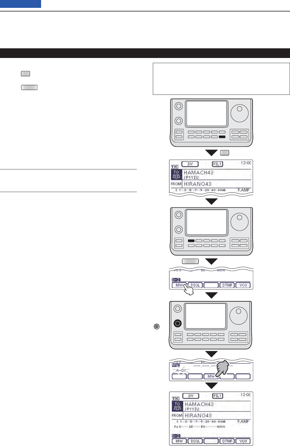
11 MEMORY OPERATION
11-6
Previous view
Programming a Memory channel (Continued)
Programming in the DR mode D
Push q
DR
to select the DR mode. (p. ??-??)
Set the desired contents. w(p. ??-??)
Push eMENU (C) one or more times to select the “D-
2” screen.
Touch [MW]( rD).
• The “MW” screen appears.
Rotate [BANK]( tL) or [M-CH](L) to select the Mem-
ory channel to be programmed.
• “---.---.-- ------” appears when no content has been pro-
grammed into the Memory channel. (Blank channel)
Touch [MW]( yD) for 1 second to program the con-
tents into the Memory channel.
Check the programmed contents on the Memory u
mode. (p. ??-??)
For your reference ✓
The Memory channel contents, programmed in the DR
mode, can also be copied to the VFO. (p. ??-??)
The L, R, C or D in the instructions indicate the part of
the controller.
L: Left side, R: Right side, C: Center bottom
D: Display (Touch panel)
Set the
desired
contents.
Blinks
Touch
[MW]
Touch
[MW] for
1 second
DR
MENU
[Example]:
Programming
“HIRANO43”
in “FROM”/
“HAMACH43”
in “TO” into
Memory
channel A-01.
[BANK]/
[M-CH]
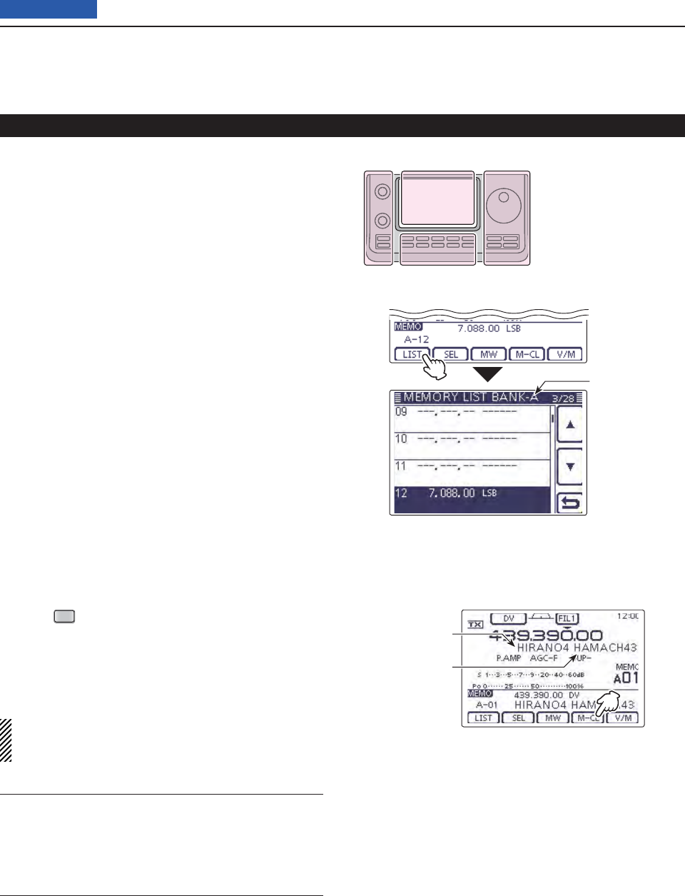
11 MEMORY OPERATION
11-7
Previous view
Programming a Memory channel (Continued)
Checking the programmed Memory con- D
tents
The programmed Memory channels can be checked on
the “MEMORY LIST” screen.
When the “M-3” (Menu 3) screen is selected, touch q
[MEMO](D) to display the “MEMO” (Memory)
screen.
Rotate [BANK]( wL) to select the Memory bank (A to
E) to be checked.
Touch [LIST]( eD) to display the “MEMORY LIST”
screen.
• Touch [∫] or [√](D) to select the displayed page.
• The Program Scan Edge Memory channels can be
checked on any band screen. “MEMORY LIST”
screen of
Bank A.
The L, R, C or D in the
instructions indicate the
part of the controller.
L: Left side
R: Right side
C: Center bottom
D: Display (Touch panel)
Left Right
Center
Display
Access repeater
call sign
Destination call
sign
Checking the Memory contents pro- D
grammed in the DR mode
Push q
DR
one or more times to cancel the DR
mode.
Touch the Memory channel number indication once w
or twice to select the Memory mode. (p. ??-??)
• The access repeater call sign and the destination call
sign appear.
When the “M-2” (Menu 2) screen is selected, touch
[CS](D) to display the call sign programmed in the
selected channel.
For your reference ✓
“FROM” and “TO” names are automatically programmed
as the Memory name.
• The Memory name is not overwritten when the memo-
ry contents are programmed into the preprogrammed
channel.
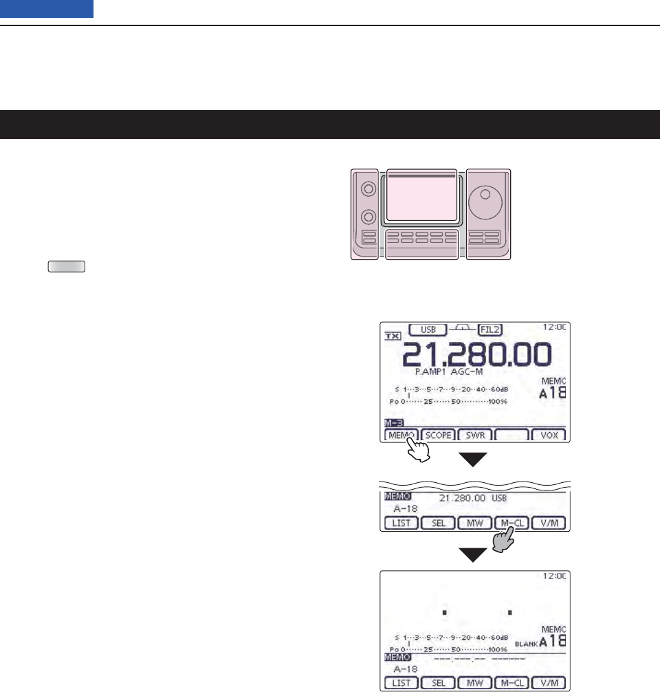
11 MEMORY OPERATION
11-8
Previous view
Any no longer used regular Memory channels can be
cleared, and then become blank channels.
Touch the Memory channel number indication once q
or twice to select the Memory mode. (p. ??-??)
Rotate [BANK]( wL) or [M-CH](L) to select the Mem-
ory channel to be cleared.
Push eMENU (C) one or more times to select the “M-
3” screen (Menu 3).
Touch [MEMO]( rD).
Touch [M-CL]( tD) for 1 second to clear the contents.
• The programmed contents disappear.
• “BLANK” appears.
Touch [M-CL]
for 1 second.
Touch
[MEMO].
Clearing a Memory channel
The L, R, C or D in the
instructions indicate the
part of the controller.
L: Left side
R: Right side
C: Center bottom
D: Display (Touch panel)
Left Right
Center
Display
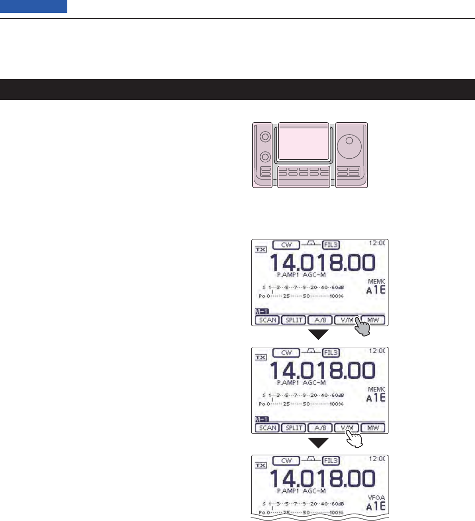
11 MEMORY OPERATION
11-9
Previous view
The Memory channel contents (frequency, operating
mode, and so on.) can be copied to the VFO.
Copying in the Memory mode D
Touch the Memory channel number indication once q
or twice to select the Memory mode. (p. ??-??)
Rotate [BANK]( wL) or [M-CH](L) to select the Mem-
ory channel to be copied.
• “BLANK” appears if the selected Memory channel is a
blank channel. In this case nothing can be copied.
Touch [V/M]( eD) for 1 second to copy the Memory
channel contents into the VFO.
Touch the Memory channel number indication to se- r
lect the VFO mode. (p. ??-??)
Copying in the VFO mode D
In the VFO mode, select the Memory channel num- ➥
ber to be copied. And then, touch [V/M] for 1 second
to copy the Memory channel contents into the se-
lected VFO.
• “BLANK” appears if the selected Memory channel is a
blank channel. In this case nothing can be copied.
Touch [V/M]
for 1 second.
Touch [V/M].
The Memory
channel contents
are transferred into
the selected VFO.
( The display does
not change.)
Copying Memory contents
The L, R, C or D in the
instructions indicate the
part of the controller.
L: Left side
R: Right side
C: Center bottom
D: Display (Touch panel)
Left Right
Center
Display
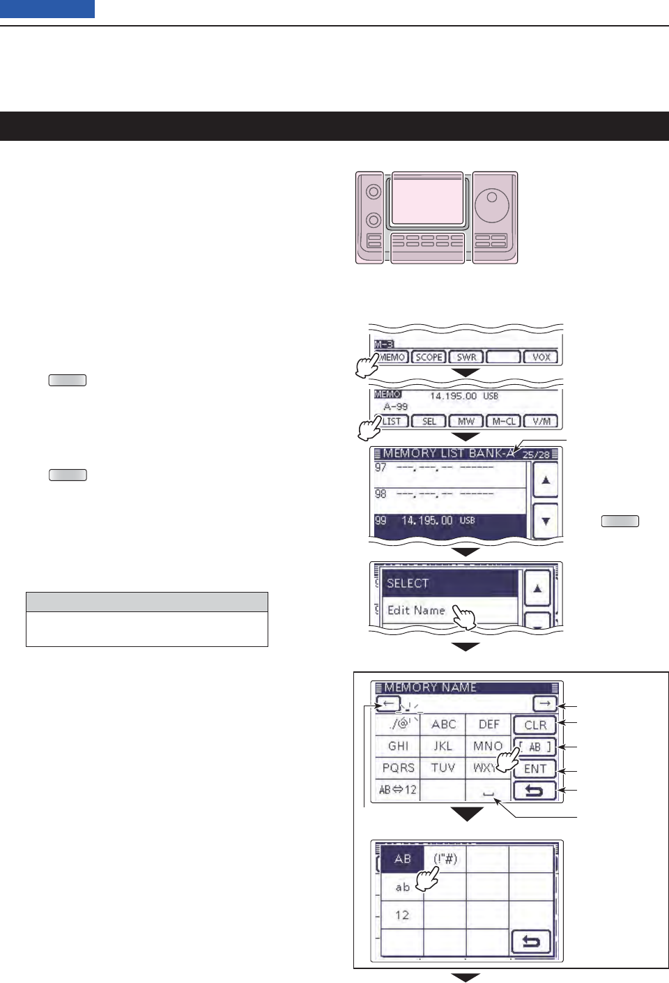
11 MEMORY OPERATION
11-10
Previous view
All Memory channels, including Scan Edges and Call
channels, can be tagged with alphanumeric names of
up to 16 characters each.
[EXAMPLE]: Programming a memory name into Mem-
ory channel 99 of Bank A.
Touch the Memory channel number indication once q
or twice to select the Memory mode. (p. ??-??)
Rotate [BANK] to select Bank A. w
Rotate [M-CH] to select the Memory channel 99. e
Push rMENU (C) one or more times to select the “M-
3” screen (Menu 3).
Touch [MEMO]( tD) to display the “MEMO” screen
(Memory Menu).
Touch [LIST]( yD) to display the “MEMORY LIST”
screen.
Push uQUICK (D), and then touch [Edit Name] to en-
ter the “MEMORY NAME” screen (Memory name
edit screen).
• A cursor appears and blinks.
• If the channel you selected is a blank channel, [Edit
Name] does not appear.
Touch the desired block one or more times to iselect
the desired character or symbol.
Selectable characters and symbols
A to Z, a to z, 0 to 9, ! # $ % & \ ? " ’ ` ^
+ – ✱ ⁄ . , : ; = < > ( ) [ ] { } ¦ _ ¯ @ (space)
• Touch “AB12” to toggle between the Alphabet input
and Number input mode.
• Touch [CLR](D) to delete the selected character, symbol
or number.
• Touch [SYMB](D) to open the Symbol character selec-
tion window.
• Touch “” to input a space.
Memory name edit screen
Input mode screen
Input a space
Move the cursor
Move the cursor
Delete a character
Select an
input mode
Enter
Cancel edit
Touch [!"#] to
open the Symbol
character selec-
tion window.
Touch [MEMO]
on the “M-3”
screen.
Touch [LIST]
Touch
[Edit Name].
“MEMORY LIST”
screen of
Bank A.
Push QUICK
Programming a Memory name
Continued on the next page. ☞
The L, R, C or D in the
instructions indicate the
part of the controller.
L: Left side
R: Right side
C: Center bottom
D: Display (Touch panel)
Left Right
Center
Display
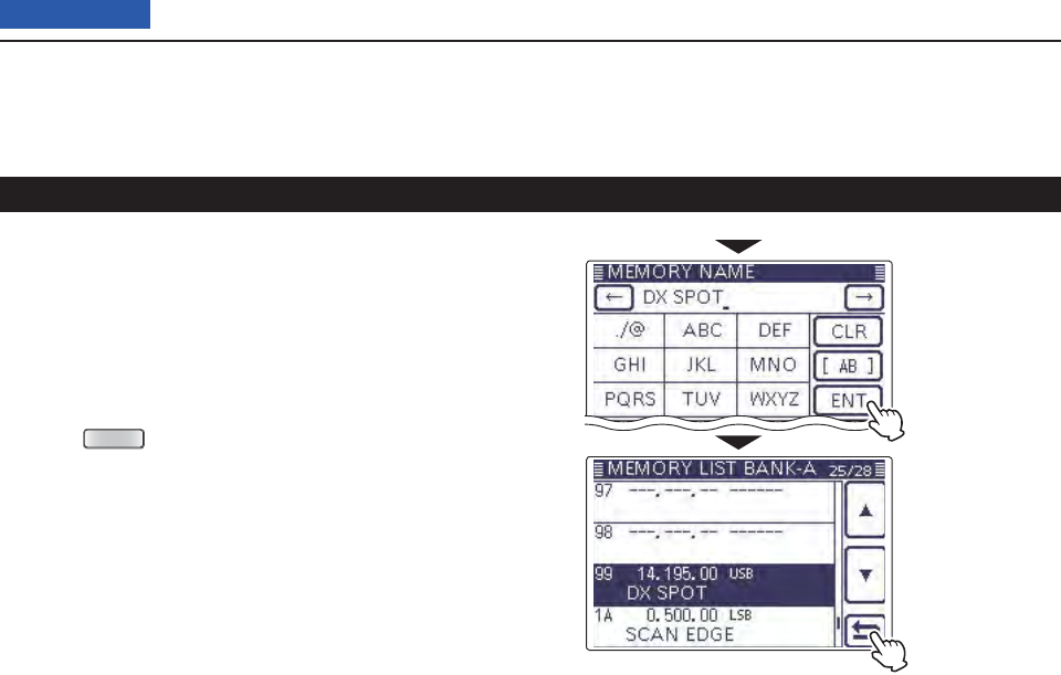
11 MEMORY OPERATION
11-11
Previous view
Touch [ o](D) to move the cursor backwards, or
touch [](D) to move the cursor forwards.
!0 Repeat steps i and o to program up to 16 char-
acters memory name, and then touch [ENT](D) to
save the name, and return to the “MEMORY LIST”
screen.
!1 Touch [](D) to return to the “MEMO” (Memory)
screen.
• Push
MENU
(C) to return to the “M-3” screen (Menu 3).
After program-
ming, touch [ENT]
Touch [] to return
to the “MEMO”
screen.
Memory name programming (Continued)
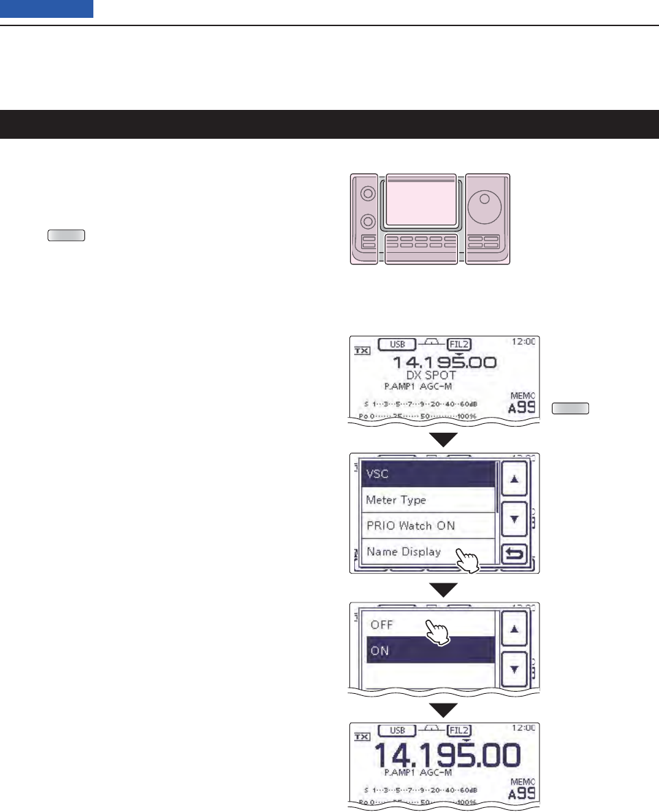
11 MEMORY OPERATION
11-12
Previous view
While in the memory mode, the programmed memory
name can be displayed.
Touch the Memory channel number indication once q
or twice to select the Memory mode. (p. ??-??)
Push wQUICK (D) to open the Quick Menu window.
Touch [Name Display]. e
Touch the desired Display type option. r
• OFF: Displays only the frequency.
• ON: Displays the memory name under the fre-
quency. (Default)
Push
QUICK .
Touch
[Name Display].
Touch “ON.”
The memory name
disappears.
Selecting a Memory display type
The L, R, C or D in the
instructions indicate the
part of the controller.
L: Left side
R: Right side
C: Center bottom
D: Display (Touch panel)
Left Right
Center
Display
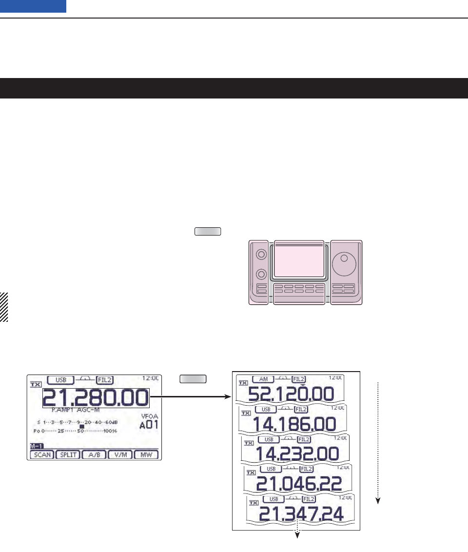
11 MEMORY OPERATION
11-13
Previous view
The transceiver has a Memo pad function to store the
displayed content for easy writing and recalling. The
Memo pads are separate from the Memory channels.
The default number of Memo pads is 5. However, you
can increase the number to 10 in the “Memopad Num-
bers” item of the Set mode, if desired. (p. ??-??)
Memo pads are convenient when you want to memo-
rize the displayed content temporarily, such as when
you fi nd a DX station in a pile-up, or when a desired
station is busy for a long time and you want to tempo-
rarily search for other stations.
Use the transceiver’s Memo pads instead of relying on
hastily scribbled notes that are easily misplaced.
Writing the displayed contents into the Memo pads D
You can store the displayed content by pushing MPAD
(R).
When you store content of the 6th Memo pad, the old-
est stored content is automatically erased, to make
room for the new content.
NOTE: Each Memo pad must have its own unique
content; Memo pads having identical content cannot
be written.
Memo pad function
Memo pads
Erased
Newest
Oldest
MPAD
In this example, 21.347.24 MHz (USB) will be
erased when 21.280.00 MHz (USB) is written.
Operating frequency of the VFO
or Memory mode
The L, R, C or D in the
instructions indicate the
part of the controller.
L: Left side
R: Right side
C: Center bottom
D: Display (Touch panel)
Left Right
Center
Display
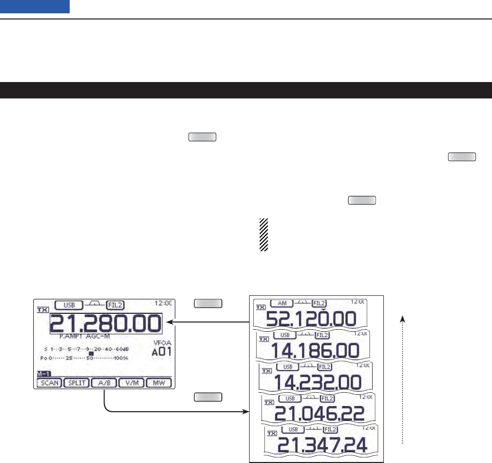
11 MEMORY OPERATION
11-14
Previous view
Memo pad function (Continued)
You can call up a Memo pad by pushing MPAD (R)
one or more times while in either the VFO or Memory
mode.
• The Memo pad content is called up, starting from the most
recently written.
When you call up a Memo pad, the previously displayed
content is automatically stored in a temporary pad. The
temporary pad can be recalled by pushing MPAD (R)
one or more times.
• You may think there are 6 Memo pads because 6 different
frequencies (5 are in Memo pads and 1 is in the temporary
pad) are called up by MPAD (R).
If you change the contents called up from a Memo
pad, the stored temporary pad content is replaced
with the changed content.
Calling up the DMemo pads
Operating frequency of the VFO
or Memory mode Memo pads
Newest
Oldest
MPAD
MPAD

12-1
Section 12 SCAN OPERATION
Previous view
12-112-1
Scan types ..............................................................................12-2
Preparation .............................................................................12-3
Scan Set mode .......................................................................12-4
Voice Squelch Control function ...........................................12-6
Scan edge programming ......................................................12-7
Programmed scan (VFO mode) ............................................12-8
Fine programmed scan (VFO mode) ....................................12-9
Memory scan (Memory mode) ..............................................12-10
Memory scan
D .........................................................................12-10
Mode Select scan
D ..................................................................12-11
Select Memory scan
D ..............................................................12-12
Setting/Cancelling Select Memory channels
D .........................12-13
∂F scan and Fine ∂F scan (VFO mode/Memory mode) .....12-14
About the
D∂F scan ................................................................12-14
About the Fine
D∂F scan ........................................................12-15
VFO frequency and a priority channel .................................12-16
DR mode and a priority channel ..........................................12-17
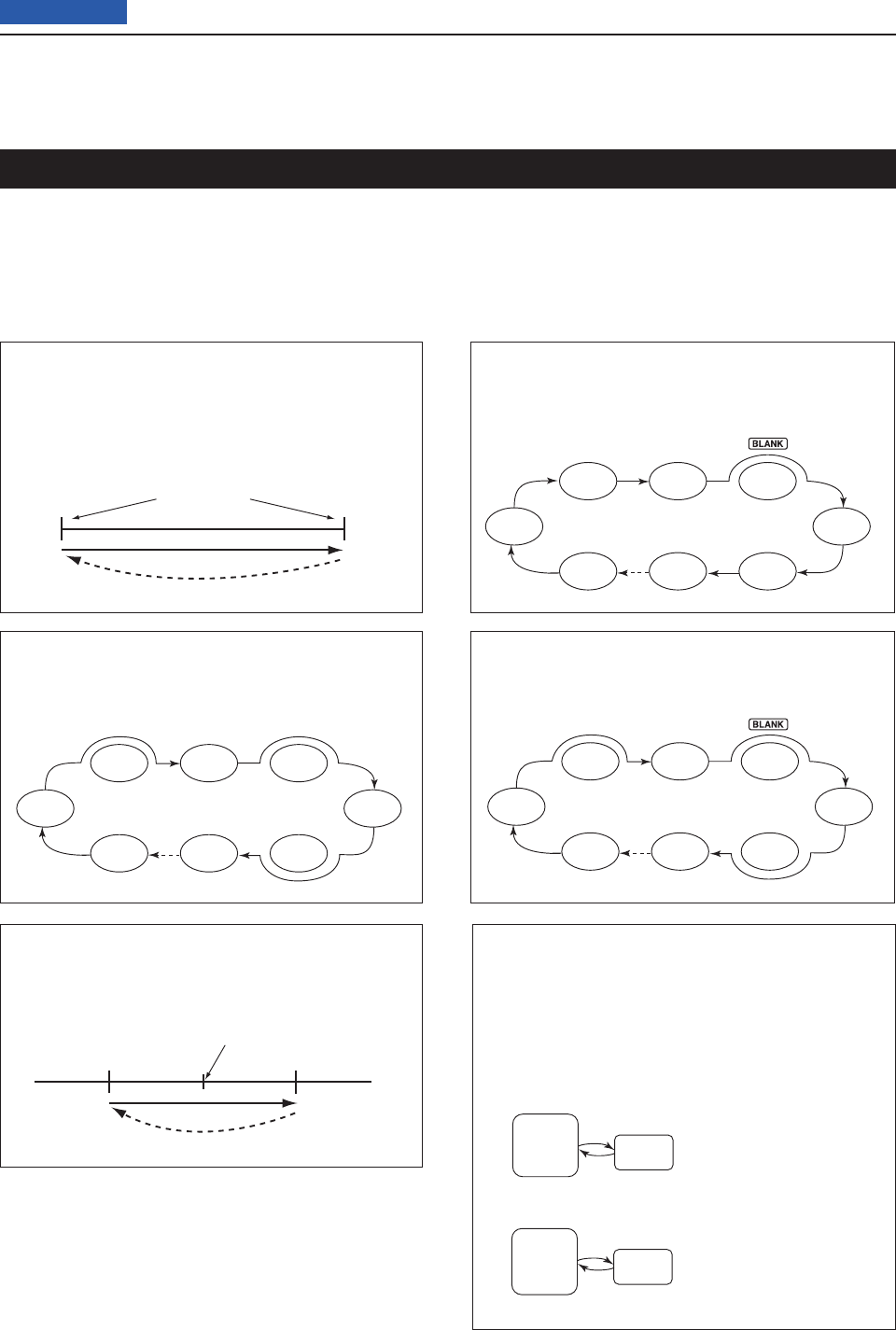
12 SCAN OPERATION
12-2
Previous view
Scan
–
∂F frequency +∂F frequency
Center frequency
(Start frequency)
Jump
Mch 1 Mch 5
Mch 2 Mch 3 Mch 4
Mch 6Mch 7Mch 99
★
★
★
★★
★ means the Select Memory channels.
★ means the Select Memory channels.
★
Mch 1
★
Mch 5
Mch 2
★
Mch 3 Mch 4
Mch 6
★
Mch 7
★
Mch 99
FM FM
USB FM CW
USBFM
FM
Scan
1A
2A
3A
1B
2B
3B
Jump
Scan edges
Scanning automatically searches for signals and makes
it easier to locate new stations for contact or listening
purposes. The IC-7100 has several scan types; Pro-
grammed scan, Memory scan, Select Memory scan,
Mode Select scan and ∂F (Delta Frequency) scan.
Rotating the Dial changes the scanning direction as the
default. The Dial functions during a scan can be set in
the Scan Set mode. (p. ??-??)
MEMORY SCAN (p. ??-??)
Repeatedly scans all programmed Memory chan-
nels.
This scan operates in the Memory mode.
PROGRAMMED SCAN (p. ??-??)
Repeatedly scans between scan edges. P1 scans
between 1A and 1B, P2 scans between 2A and 2B,
and P3 scans between 3A and 3B frequencies.
This scan operates in the VFO mode.
SELECT MEMORY SCAN (p. ??-??)
Repeatedly scans all Select Memory channels.
This scan operates in the Memory mode.
MODE SELECT SCAN (p. ??-??)
Repeatedly scans all selected Memory mode chan-
nels.
This scan operates in the Memory mode.
∂F SCAN (p. ??-??)
Repeatedly scans within the ∂F span area.
This scan operates in both VFO and Memory
modes.
Scan types
PRIORITY SCAN (p. ??-??)
Checks the selected priority channel every 5 sec-
onds:
• While receiving on a VFO frequency
• During a VFO mode scan for the VFO mode
• While receiving on a repeater in the DR mode
• During a DR mode scan for the DR mode
This scan operates in the VFO or DR mode.
A VFO frequency, Memo-
ry channel, Call channel
or Program Scan Edge
channel can be selected
as the priority channel.
Checks every
5 seconds.
Receiving/Scan
(5 seconds)
VFO
mode Priority
channel
Receiving/Scan
(5 seconds)
DR
mode Priority
channel
Checks eve
r
5 seconds
A Memory channel, Call
channel or Program Scan
Edge channel can be
selected as the priority
channel.

12 SCAN OPERATION
12-3
Previous view
For a Programmed scan:
Program scan edge frequencies into Program Scan
Edge channels “1A–3A” and “1B–3B.” (p. ??-??)
For a Memory scan:
Program two or more Memory channels. (Program
Scan Edge channels will not be scanned.) (p. ??-??)
For a Mode Select scan:
Program two or more Memory channels, all with the
same operating mode. (p. ??-??)
For a Select Memory scan:
Program two or more Memory channels as Select
Memory channels. (p. ??-??)
For a ∂F scan:
Set the ∂F span (∂F scan range) in the “SCAN” screen.
(p. ??-??)
• Scan Resume function
You can set the scan to resume or cancel when detect-
ing a signal in the Scan Set mode. The Scan Resume
function must be set before starting a scan. (p. ??-??)
• Scan speed
The scan speed can be set to fast or slow in the Scan
Set mode. (p. ??-??)
• Dial function
How the Dial functions during a scan, can be set in the
Scan Set mode. (p. ??-??)
• Squelch status
❍ The scan starts with the squelch open
For a programmed scan:
When the tuning step is 1 kHz or less:
The scan continues until it is manually stopped— it
does not pause*, even if signals are detected.
* The scan is paused when the squelch is closed and then
opened. The scan resumes, or is cancelled, depending on
the Scan Resume setting.
When the tuning step is 5 kHz or more:
If Scan Resume is ON, the scan pauses on each step
when a signal is detected, then resumes.
If the Scan Resume is OFF, the scan does not start.
For memory scan:
If Scan Resume is ON, the scan pauses on each channel
when a signal is detected, then resumes.
If Scan Resume is OFF, the scan does not start.
❍ The scan starts with the squelch closed
The scan pauses when a signal is detected. The scan
resumes, or is cancelled, depending on the Scan Re-
sume setting.
Preparation
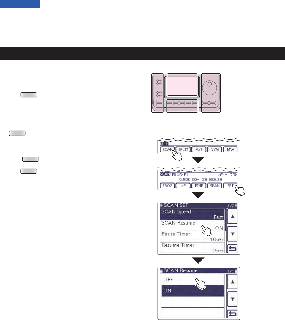
12 SCAN OPERATION
12-4
Previous view
Scan Set mode
The Scan speed, Scan Resume function, Pause Timer,
Resume Timer and the Dial function can be set in the
Scan Set mode.
Push qMENU (C) one or more times to select the “M-
1” (Menu 1) screen.
Touch [SCAN]( wD) to display the “SCAN” screen.
Touch [SET]( eD) to display the “SCAN SET” screen.
Touch the desired item. r
• To go back the previous tree level, touch [](D), or
MENU (C).
Touch a desired option shown on the display. t
• When you touch an option, it is automatically saved and
goes back the previous tree level.
• Push QUICK (C), and then touch “Default” to reset to the
default setting, if desired.
Push yMENU (C) to return to the “SCAN” screen.
Touch [SCAN]
Touch
[SET]
Touch a desired
item.
( Example:
SCAN Resume)
Touch a desired
option.
(Example: OFF)
The L, R, C or D in the
instructions indicate the
part of the controller.
L: Left side
R: Right side
C: Center bottom
D: Display (Touch panel)
Left Right
Center
Display

12 SCAN OPERATION
12-5
Previous view
SCAN Speed (Default: Fast)
Select the desired scan speed between slow and fast.
• Slow: The scan is slower.
• Fast: The scan is faster.
SCAN Resume (Default: ON)
Set the Scan Resume function ON or OFF.
• OFF: When a signal is detected, the scan is can-
celled.
• ON: When a signal is received during a scan, the
scan pauses for the set period of time in the
“Pause Timer” setting, and then resumes.
When the signal disappears, the scan resumes
after the set period of time in the “Resume Tim-
er” setting.
Pause Timer (Default: 10 sec)
Select the scan Pause Timer.
When a signal is received, the scan pauses according
to this setting.
When the “Resume Timer” is set to “0 sec,” this setting
is invalid.
• 2 to 20 sec: When a signal disappears while pausing
the scan for 2 to 20 seconds (in 2 sec-
onds steps), the scan resumes accord-
ing to the setting in the Resume Timer.
• Hold: When receiving a signal, the scan paus-
es and resumes when it disappears, ac-
cording to the setting in Resume Timer.
Resume Timer (Default: ON)
Select the scan Resume Timer.
When a received signal disappears, the scan resumes
according to this setting.
• 0 sec: The scan resumes immediately after the
signal disappears.
• 1 to 5 sec: The scan resumes 1 to 5 seconds after
the signal disappears.
• Hold: The scan remains paused according to
the Pause Timer, even if the signal disap-
pears.
- Rotate the Dial to resume the scan.
- When “Pause Timer” is set to 2 to 20
seconds, the scan resumes, according
to the “Pause Timer” setting.
MAIN DIAL (SCAN) (Default: Up/Down)
Select the function of the Dial while scanning.
• OFF : Rotating the Dial cancels the scan.
• Up/Down : Rotating the Dial changes the scanning
direction.
Scan Set mode (Continued)
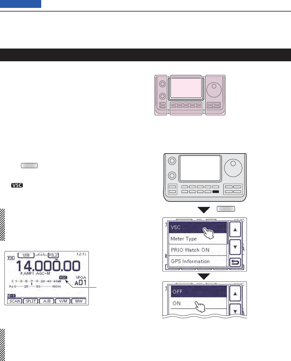
12 SCAN OPERATION
12-6
Previous view
Voice Squelch Control function
(Mode: SSB/AM/FM
)
This function is useful when you do not want unmodu-
lated signals pausing or cancelling a scan. When the
Voice Squelch Control (VSC) function is ON, the receiv-
er checks received signals for voice components.
The scan pauses, or is cancelled, if a received signal
includes voice components, and the tone of the voice
components changes within 1 second. See “Squelch
status” as described on page ??-??.
The scan resumes if the received signal includes no
voice components, or the tone of the voice components
does not change within 1 second.
Select SSB, AM or FM as the operating mode. q
Push wQUICK (D) to open the Quick Menu window.
Touch [VSC]. e
Touch the desired option. r
• “ ” appears when the VSC function is ON.
• When you touch an option, it is automatically saved and
goes back the previous tree level.
• The VSC function is usable in the phone modes
(SSB, AM and FM).
• The VSC function resumes the scan on unmodu-
lated signals, regardless of whether the Scan Re-
sume function is set to ON or OFF.
QUICK
Touch [VSC].
Touch a desired
option.
(Example: ON)
Appears
The L, R, C or D in the
instructions indicate the
part of the controller.
L: Left side
R: Right side
C: Center bottom
D: Display (Touch panel)
Left Right
Center
Display
NOTE: While listening to the radio with the VSC
function ON, the audio may be interrupted. The mu-
sic or a commercial, including narration or BGM, is
not detected as an audio component. In this case,
turn OFF the VSC function.
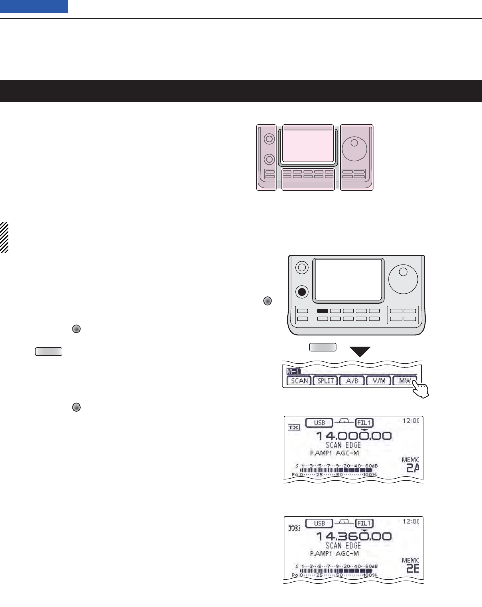
12 SCAN OPERATION
12-7
Previous view
Memory channels 1A–3A and 1B–3B are the Program
Scan Edge channels. They are used to program the up-
per and lower frequency edges for programmed scans.
(p. ??-??)
Factory default frequency and operating modes are
programmed into the Scan Edge channels: 1A/1B are
for HF, 2A/2B are for the 144 MHz, and 3A/3B are for
the 430 MHz frequency bands, and you can reprogram
it as desired.
If both upper and lower band edges are programmed
with the same frequency, a programmed scan can-
not start.
EXAMPLE: Programming 14.000.00 MHz into 2A and
14.360.00 MHz into 2B.
Touch the Memory channel number indication once q
or twice to select the VFO mode. (p. ??-??)
Rotate [M-CH] w(L) to select scan edge 2A.
Set 14.000.00 MHz as the lower frequency. e
Push rMENU (C) one or more times to select the “M-
1” (Menu 1) screen.
Touch [MW]( tD) for 1 second to program 14.000.00
MHz into scan edge 2A.
• Three beeps sound when the programming is complete.
Rotate [M-CH] y(L) to select scan edge 2B.
Set 14.360.00 MHz as the upper frequency. u
Touch [MW] for 1 second to program 14.360.00 MHz i
into scan edge 2B.
• Three beeps sound when the programming is complete.
If 2A/2B is selected as the scanning range when a o
programmed scan is started, it will search for signals
between 14.000.00 MHz and 14.360.00 MHz. (p. ??-
??)
[M-CH]
MENU
Touch [MW]
for 1 second
Programming 14.000.00 MHz/USB into 2A.
Programming 14.360.00 MHz/USB into 2B.
Scan edge programming
The L, R, C or D in the
instructions indicate the
part of the controller.
L: Left side
R: Right side
C: Center bottom
D: Display (Touch panel)
Left Right
Center
Display
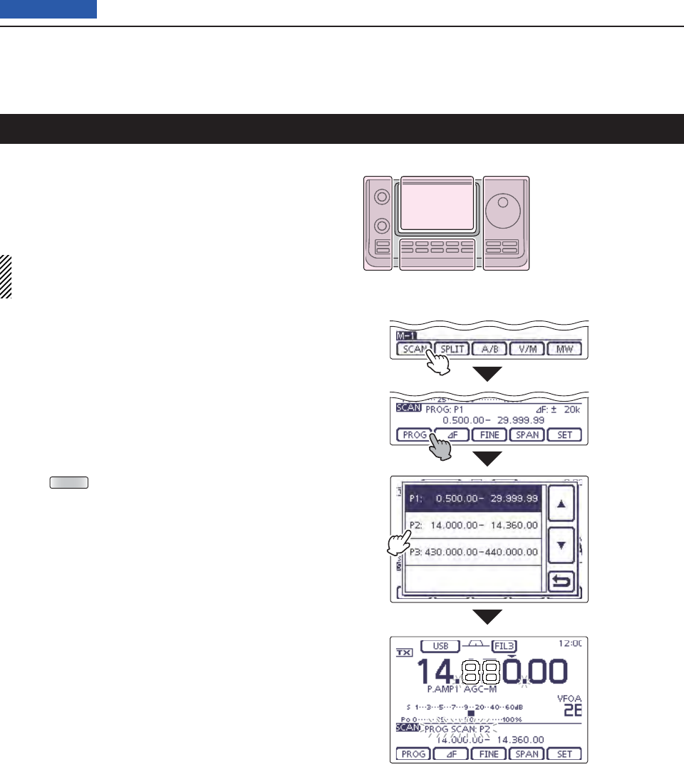
12 SCAN OPERATION
12-8
Previous view
A programmed scan searches for signals between Pro-
gram Scan Edge channels “1A–3A” and “1B–3B.”
Before starting the programmed scan, scan edges must
be programmed into these channels.
See the previous page for scan edge programming.
If the same frequencies are programmed into the
Program Scan Edge channels, the programmed
scan will not start.
Touch the Memory channel number indication once q
or twice to select the VFO mode. (p. ??-??)
Touch the mode icon to display the Mode selection w
screen, and then touch the desired operating mode.
• The operating mode can also be changed while scan-
ning.
Touch the frequency ‘kHz’ area on the display for 1 e
second to display the Tuning step selection screen,
and then touch the desired tuning step. (p. ??-??)
• The tuning step can also be changed while scanning.
Push rMENU (C) one or more times to select the “M-
1” (Menu 1) screen.
t
Touch
[SCAN](D) to display the “SCAN” screen.
Set [RF/SQL] open or closed. y
• The scan performance differs, depending on the squelch
setting when the scan was started. See page ??-?? for
details.
• If the [RF/SQL] control function is set to “AUTO,” the
squelch is always open in the SSB, CW and RTTY
modes. (pp. ??-??, ??-??)
Touch [PROG]( uD) for 1 second, and then touch the
desired scan range between “P1,” “P2” and “P3.”
• The scan searches between programmed scan channels
1A–1B (P1), 2A–2B (P2) or 3A–3B (P3).
• Example: P2: 14.000.00–14.360.00
Touch [PROG]( iD) to start the programmed scan.
• The MHz and kHz decimal points, and the selected scan
range display blink while scanning.
• If
“Up/Down” is selected as
the “MAIN DIAL (SCAN)” op-
tion
in the Scan Set mode, rotating the Dial changes the
scanning direction. (p. ??-??)
When the scan detects a signal, the scan stops, o
pauses or ignores it, depending on the Scan Resume
function, the VSC function or the squelch status.
!0 Push [PROG](D) to cancel the scan.
While Programmed scanning
Touch
[SCAN]
Touch [PROG]
for 1 second.
Touch the de-
sired scan
range (Exam-
ple: P2)
Programmed scan (VFO mode)
The L, R, C or D in the
instructions indicate the
part of the controller.
L: Left side
R: Right side
C: Center bottom
D: Display (Touch panel)
Left Right
Center
Display
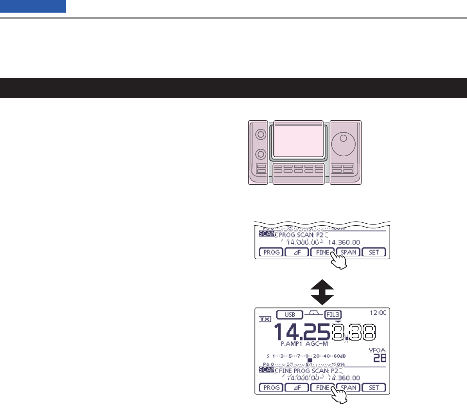
12 SCAN OPERATION
12-9
Previous view
Fine programmed scan (VFO mode)
When a signal is received during a Fine programmed
scan, the scanning tuning step is temporarily set to
10 Hz and the scan speed decreases.
Start the programmed scan. q
• Follow steps q through i as described on page ??-??.
While scanning, touch [FINE]( wD) to switch the scan
function between a programmed scan and a Fine
programmed scan.
Touch [PROG]( eD) to cancel the scan.
While Fine programmed scanning
While Programmed scanning
Touch [FINE].
Touch [FINE].
The L, R, C or D in the
instructions indicate the
part of the controller.
L: Left side
R: Right side
C: Center bottom
D: Display (Touch panel)
Left Right
Center
Display
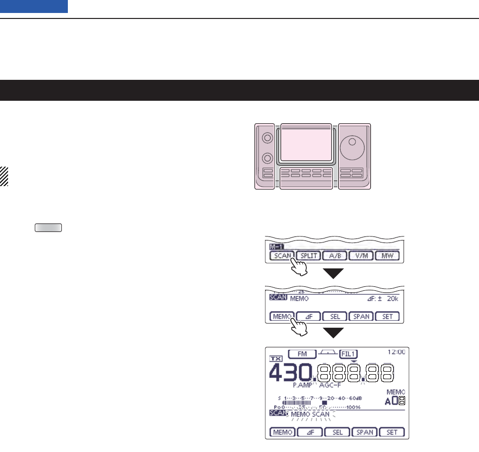
12 SCAN OPERATION
12-10
Previous view
Memory scan D
A Memory scan searches for signals through Memory
channels 1 to 99.
Blank (unprogrammed) Memory channels are skipped.
NOTE: For a Memory scan to start, two or more
Memory channels must be programmed. (p. ??-??)
Touch the Memory channel number indication once q
or twice to select the Memory mode. (p. ??-??)
Push wMENU (C) one or more times to select the “M-
1” (Menu 1) screen.
e
Touch
[SCAN](D) to display the “SCAN” screen.
Set [RF/SQL] open or closed. r
• The scan performance differs, depending on the squelch
setting when the scan was started. See page 146 for de-
tails.
• If the [RF/SQL] control function is set to “AUTO,” the
squelch is always open in the SSB, CW and RTTY
modes. (pp. ??-??, ??-??)
Touch [MEMO]( tD) to start the Memory scan.
• The MHz and kHz decimal points, and “MEMO SCAN”
blink while scanning.
• If “Up/Down” is selected as the “MAIN DIAL (SCAN)” op-
tion in the Scan Set mode, rotating the Dial changes the
scanning direction. (p. ??)
Touch [MEMO]( yD) to cancel the scan.
While Memory scanning
Touch
[SCAN]
Touch [MEMO]
Memory scan (Memory mode)
The L, R, C or D in the
instructions indicate the
part of the controller.
L: Left side
R: Right side
C: Center bottom
D: Display (Touch panel)
Left Right
Center
Display
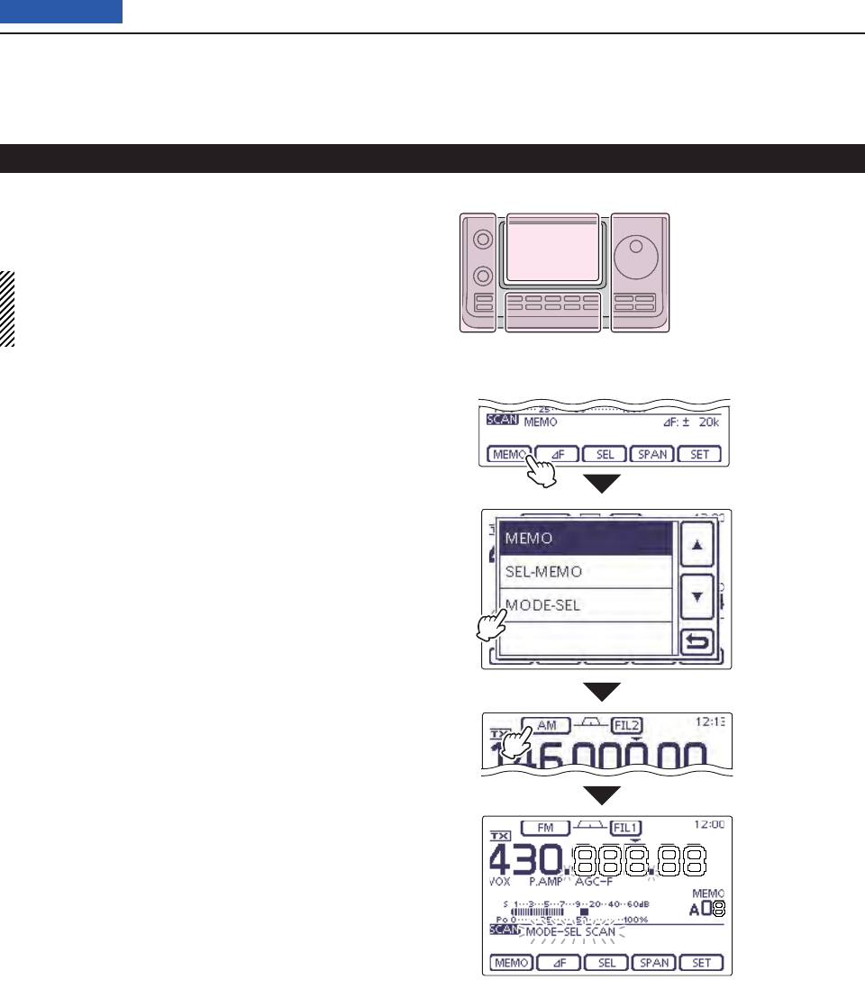
12 SCAN OPERATION
12-11
Previous view
Mode Select scan D
Repeatedly scans all Memory channels with the same
operating mode as the displayed mode.
NOTE: For a Mode Select scan to start, two or more
Memory channels must be programmed, and their
operating mode must be the same as the displayed
mode.
Follow steps qq through e as described above to
display the “SCAN” screen.
Touch [MEMO]( wD) for 1 second, and then touch
“MODE-SEL” to start the Mode Select scan.
• The MHz and kHz decimal points, and “MODE-SEL
SCAN” blink while scanning.
• If
“Up/Down” is selected as
the “MAIN DIAL (SCAN)” op-
tion
in the Scan Set mode, rotating the Dial changes the
scanning direction. (p. ??-??)
To change the operating mode while scanning, touch e
the mode icon to display the Mode selection screen,
and then touch the desired operating mode.
Push [MEMO]( rD) to cancel the scan.
While Mode Select scanning
Touch [MEMO]
for 1 second
Touch
“MODE-SEL.”
Touch the mode
icon, and then
touch the de-
sired operating
mode
Memory scan (Memory mode) (Continued)
The L, R, C or D in the
instructions indicate the
part of the controller.
L: Left side
R: Right side
C: Center bottom
D: Display (Touch panel)
Left Right
Center
Display
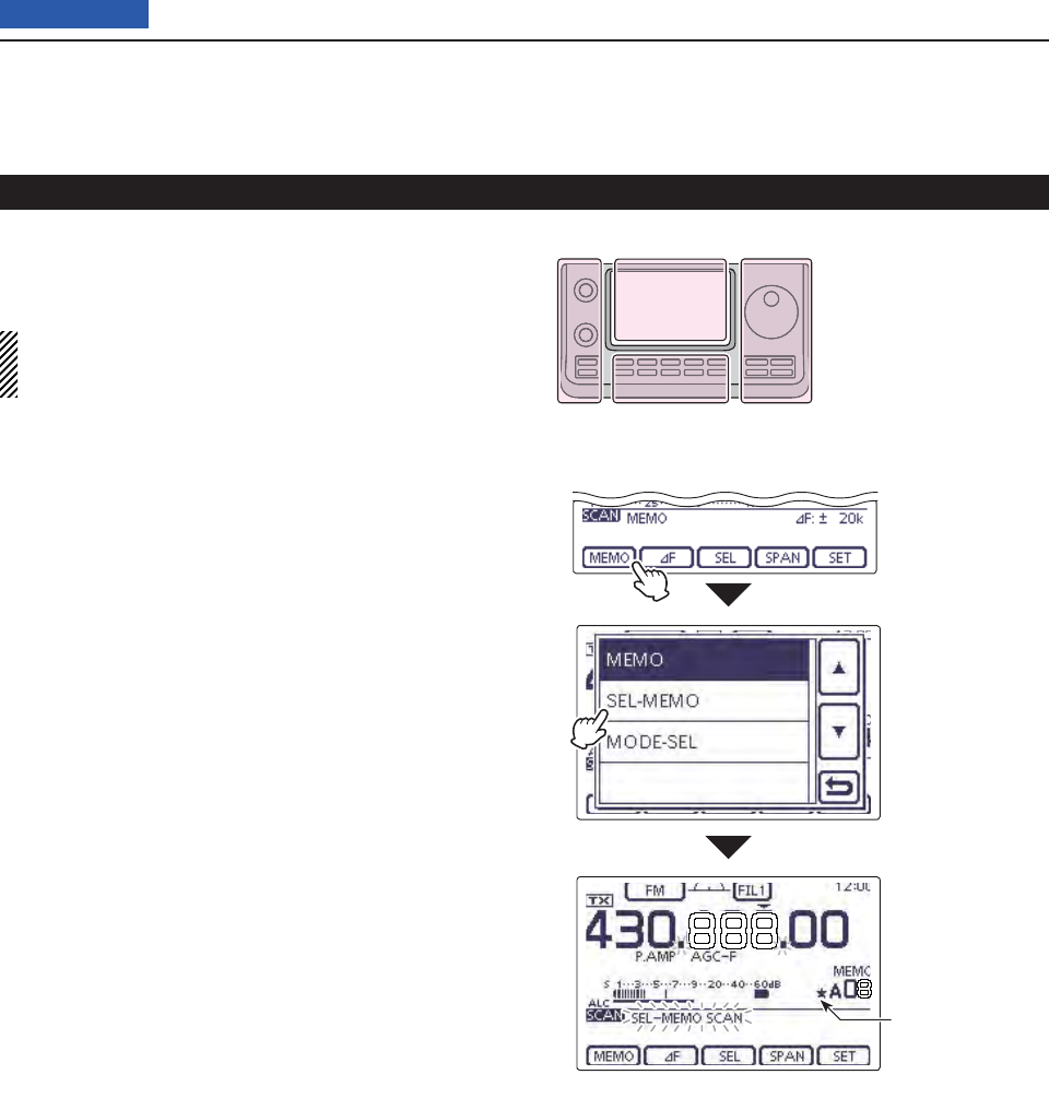
12 SCAN OPERATION
12-12
Previous view
Select Memory scan D
The Select Memory scan searches for signals through
Memory channels specifi ed as “” (Select).
NOTE: For a Select Memory scan to start, two or
more Memory channels must be designated as Se-
lect Memory channels. (See below)
Follow steps qq through e as described on the page
??-?? to display the “SCAN” screen.
Touch [MEMO]( wD) for 1 second, and then touch
“SEL-MEMO” to start the Select Memory scan.
• The MHz and kHz decimal points, and “SEL–MEMO
SCAN” blink while scanning.
• If
“Up/Down” is selected as
the “MAIN DIAL (SCAN)” op-
tion
in the Scan Set mode, rotating the Dial changes the
scanning direction. (p. ??-??)
Push [MEMO]( eD) to cancel the scan.
While Select Memory scanning
Touch [MEMO]
for 1 second.
Touch
“SEL-MEMO.”
Appears
Memory scan (Memory mode) (Continued)
The L, R, C or D in the
instructions indicate the
part of the controller.
L: Left side
R: Right side
C: Center bottom
D: Display (Touch panel)
Left Right
Center
Display
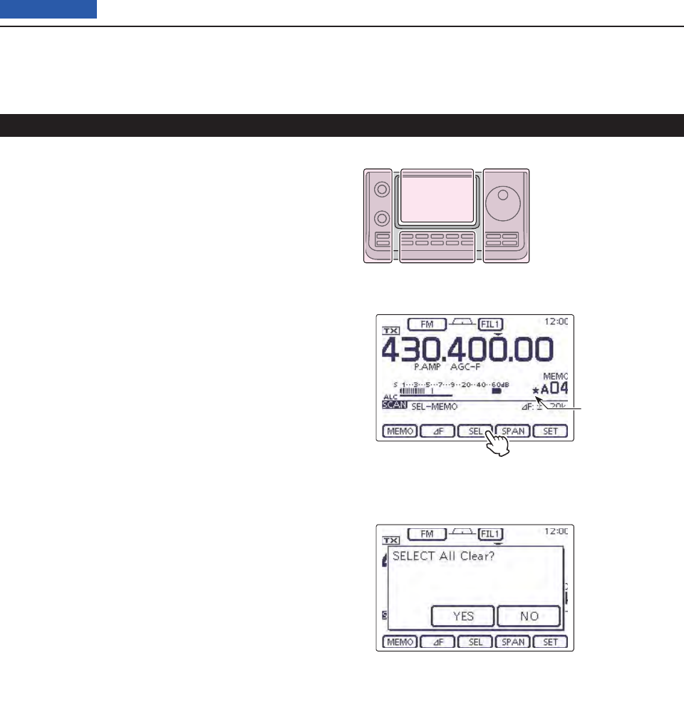
12 SCAN OPERATION
12-13
Previous view
Memory scan (Memory mode) (Continued)
All Memory channels can be set as Select Memory chan-
nels, except for the Scan Edge and Call channels.
When the “SCAN” screen or the “MEMO” screen ➥
(Memory Menu) is displayed, touch [SEL] to set or
cancel the displayed Memory channel as a Select
Memory channel.
• “” appears when the channel is set as a Select Memory
channel.
• An error beep sounds when the displayed Memory chan-
nel is a blank channel.
• Touching [SEL] for 1 second displays “SELECT ALL
Clear?.” Touch [YES](F-4) to clear all Select Memory
channel settings.
Setting/Cancelling Select Memory channels D
“SCAN” screen
When the channel is set as a Select
Memory channel.
“SELECT ALL Clear?” screen
After touching [SEL] for 1 second
to clear all Select Memory channel
settings.
Appears
The L, R, C or D in the
instructions indicate the
part of the controller.
L: Left side
R: Right side
C: Center bottom
D: Display (Touch panel)
Left Right
Center
Display
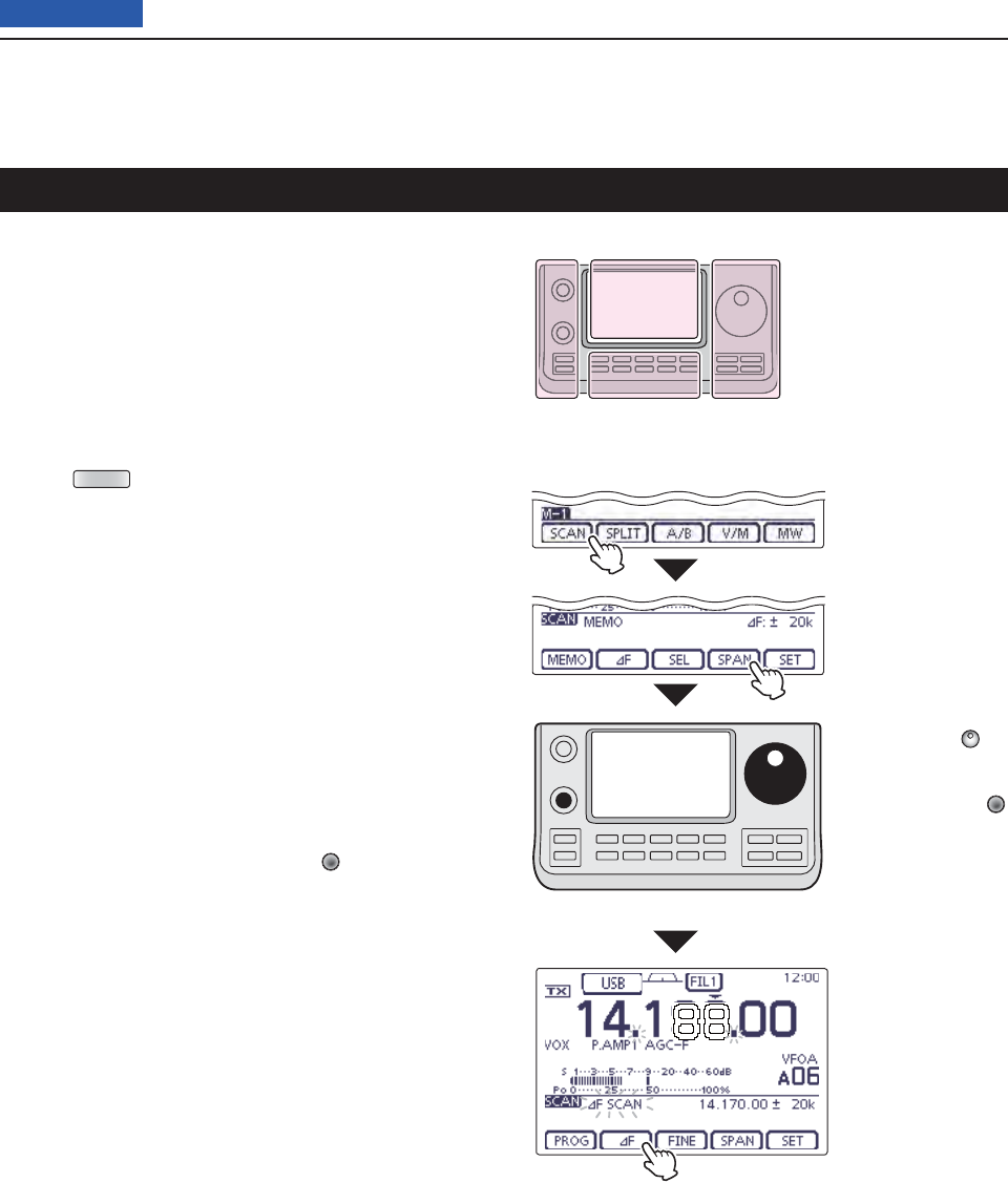
12 SCAN OPERATION
12-14
Previous view
About the D∂F scan
∂F (Delta Frequency) scan searches for signals within
the specifi ed range with the displayed VFO frequency
or Memory channel frequency as the center frequency.
The frequency range is specifi ed by the width of the
selected span.
Touch the Memory channel number indication once q
or twice to select the VFO mode or Memory mode.
(p. ??-??)
Push wMENU (C) one or more times to select the “M-
1” (Menu 1) screen.
e
Touch
[SCAN](D) to display the “SCAN” screen.
Set [RF/SQL] open or closed. r
• The scan performance differs, depending on the squelch
setting when the scan was started. See page 146 for de-
tails.
• If the [RF/SQL] control function is set to “AUTO,” the
squelch is always open in the SSB, CW and RTTY
modes. (pp. ??-??, ??-??)
Touch [SPAN]( tD) one or more times to select the
desired ∂F span width.
• ±5 kHz, ±10 kHz, ±20 kHz, ±50 kHz, ±100 kHz, ±500 kHz
and ±1 MHz are selectable.
Set the center frequency of the y∂F scan.
• In the VFO mode, rotate the Dial to set the center fre-
quency.
• In the memory mode, rotate [M-CH] (L) to select the
desired Memory channel whose frequency will be the
center frequency.
Touch [ u∂F](D) to start the ∂F scan.
• “∂F SCAN,” the MHz and kHz decimal points blink while
scanning.
• If
“Up/Down” is selected as
the “MAIN DIAL (SCAN)” op-
tion
in the Scan Set mode, rotating the Dial changes the
scanning direction. (p. ??-??)
When the scan detects a signal, the scan stops, i
pauses or ignores it, depending on the Scan Re-
sume function, VSC function or the squelch status.
Touch [ o∂F](D) again to cancel the ∂F scan.
While ∂F scanning (VFO mode)
Set the center frequency
Touch
[SCAN]
Touch [SPAN] one or
more times to select
the ∂F span width.
∂F scan and Fine ∂F scan (VFO mode/Memory mode)
Rotate the Dial
(VFO mode)
Rotate the [M-CH]
(Memory mode)
The L, R, C or D in the
instructions indicate the
part of the controller.
L: Left side
R: Right side
C: Center bottom
D: Display (Touch panel)
Left Right
Center
Display
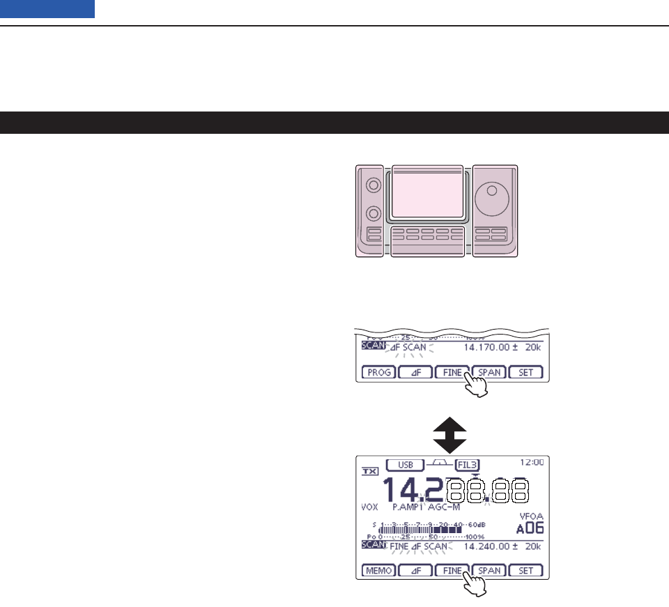
12 SCAN OPERATION
12-15
Previous view
About the Fine D∂F scan
When a signal is received during a Fine ∂F scan, the
scanning tuning step is temporarily set to 10 Hz and the
scan speed decreases.
Start q∂F scan.
• Follow steps q through u as described on page ??-??.
While scanning, touch [FINE]( wD) to switch the scan
function between ∂F scan and Fine ∂F scan.
Touch [ e∂F](D) to cancel the scan.
While Fine ∂F scanning
While ∂F scanning
Touch [FINE]
Touch [FINE]
∂F scan and Fine ∂F scan (VFO mode/Memory mode) (Continued)
The L, R, C or D in the
instructions indicate the
part of the controller.
L: Left side
R: Right side
C: Center bottom
D: Display (Touch panel)
Left Right
Center
Display
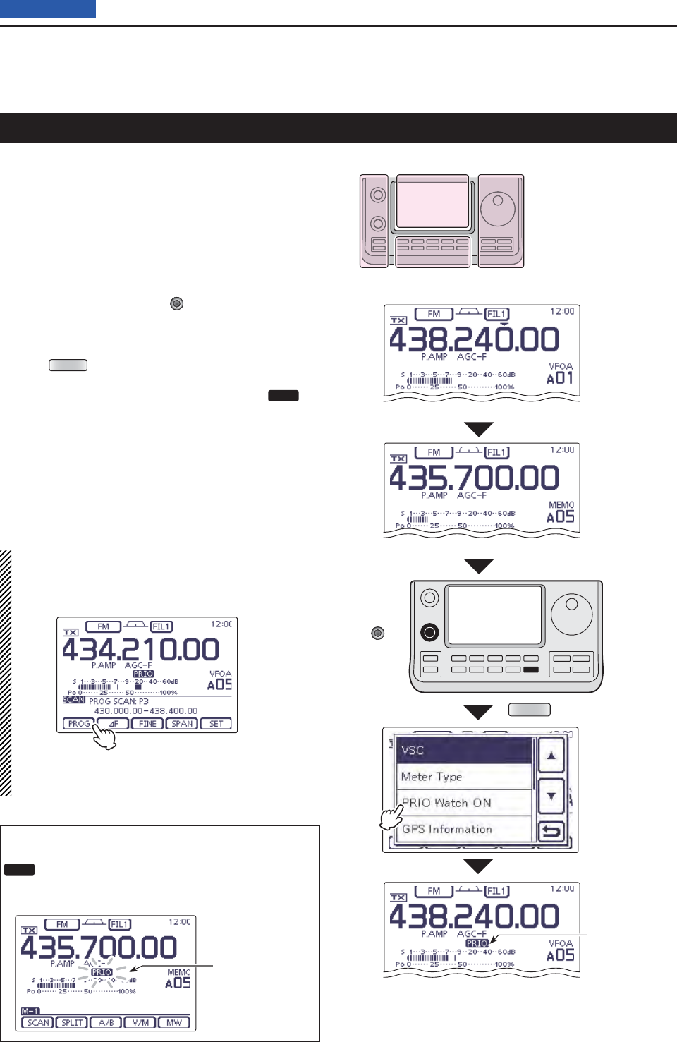
12 SCAN OPERATION
12-16
Previous view
The receive frequency and the operating mode setting
Set the priority channel (Example: A05)
QUICK
[BANK]/
[M-CH]
Select the VFO
mode
Select the
Memory mode
Touch
“PRIO Watch ON”
While Priority
scanning
VFO frequency and a priority channel
Checks the selected priority channel every 5 seconds,
while receiving on a VFO frequency.
Touch the Memory channel number indication once q
or twice to select the VFO mode. (p. ??-??)
Set the receive frequency and the operating mode. w
(p. ??-??)
Touch the Memory channel number indication to se- e
lect the Memory mode. (p. ??-??)
Rotate [BANK] or [M-CH] r(L) to set the priority
channel.
•
Memory channel, Call channel or Program Scan Edge chan-
nel can be selected as the priority channel.
Push tQUICK (D) to open the Quick Menu window.
Touch “PRIO Watch ON” to start the Priority scan. y
• The VFO mode is automatically selected, and PRIO ap-
pears.
• To cancel the Priority scan, touch “PRIO Watch OFF” in
the Quick Menu window.
When a signal is received on the priority channel
The Priority channel is automatically selected, and
PRIO blinks on the screen.
• The scan pause timer and resume settings are the same
as for a normal scan.
Priority scan au-
tomatically paus-
es.
NOTE:
When the VFO mode is selected, you can normally
operate the transceiver; the operating frequency set-
ting, the scanning operation and so on.
The L, R, C or D in the
instructions indicate the
part of the controller.
L: Left side
R: Right side
C: Center bottom
D: Display (Touch panel)
Left Right
Center
Display
To start the Programmed scan during the
Priority scan, touch [SCAN] in the “M-1”
(Menu 1) screen, and then touch [PROG].
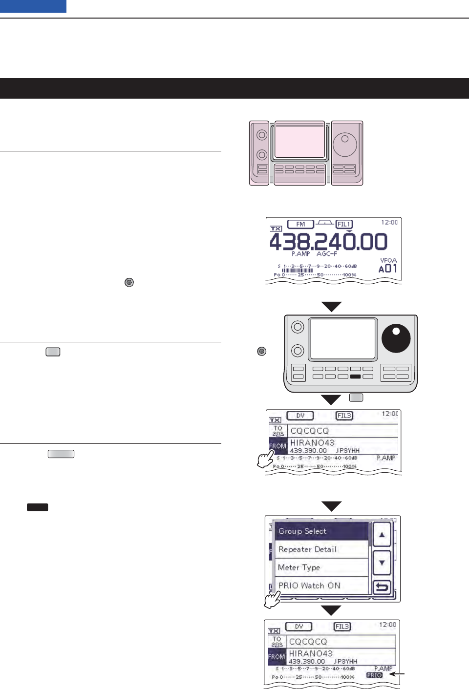
12 SCAN OPERATION
12-17
Previous view
The receive frequency and the operating mode setting
[BANK]/
[M-CH]
DR
When the VFO
frequency is set
as the priority
channel
Select the repeater to receive
(Example: Hirano43)
Select the DR
mode
Touch
“PRIO Watch ON”
Appears while
the priority
scanning
Set the
receive
frequency
in the VFO
mode.
Checks the selected priority channel every 5 seconds,
while receiving a repeater in the DR mode.
Set the priority channel1.
• Using the VFO frequency
q Touch the Memory channel number indication
once or twice to select the VFO mode. (p. ??-??)
w Set the receive frequency and the operating
mode. (p. ??-??)
• Using the Memory/Call/Program Scan Edge
channel
q Touch the Memory channel number indication
once or twice to select the Memory mode. (p. ??-
??)
w Rotate [BANK] or [M-CH] (L) to set the priority
channel.
•
Memory channel, Call channel or Program Scan Edge
channel can be selected as the priority channel.
Select the repeater in the DR mode2.
q Push
DR
(C) to select the DR mode. (p. ??-??)
w Touch “FROM” (Access repeater), if “FROM” is
not selected.
e Rotate the Dial to select the desired repeater.
•
You can select a repeater in the “FROM SELECT” screen
that is displayed after touching the repeater name on
“FROM.”
Start the Priority scan3.
q Push QUICK (D) to open the Quick Menu win-
dow.
w Touch “PRIO Watch ON” to start the Priority
scan.
• The DR mode screen is automatically selected, and
PRIO appears.
• To cancel the Priority scan, touch “PRIO Watch OFF”
in the Quick Menu window.
DR mode and a priority channel
The L, R, C or D in the
instructions indicate the
part of the controller.
L: Left side
R: Right side
C: Center bottom
D: Display (Touch panel)
Left Right
Center
Display
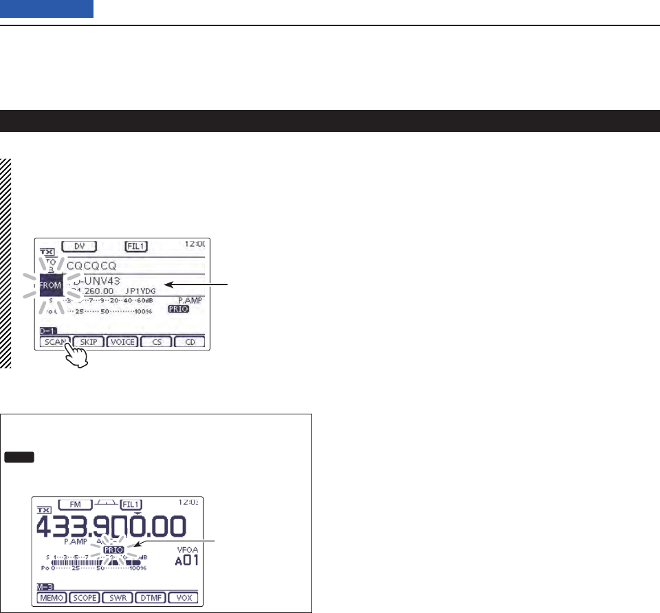
12 SCAN OPERATION
12-18
Previous view
DR mode and a priority channel (Continued)
NOTE:
When the DR mode screen is displayed, you can
normally use the DR mode; “FROM” (Access
repeater)/“TO” (Destination) selection, the DR mode
scanning and so on.
To start the DR
mode scan,
touch [SCAN]
in the “D-1”
screen.
When a signal is received on the priority channel
The Priority channel is automatically selected, and
PRIO blinks on the screen.
• The scan pause timer and resume settings are the same
as for a normal scan.
Priority scan au-
tomatically paus-
es.

13-1
Section 13 USING AN SD CARD
Previous view
About the SD card .................................................................13-2
Saving data onto the SD card ...............................................13-3
Inserting the SD card ............................................................13-4
Formatting the SD card
D .........................................................13-4
Removing the SD card ..........................................................13-5
Removing the SD card while the transceiver’s power is ON
D .13-5
Saving the setting data onto an SD card .............................13-6
Saving with a different fi le name ..........................................13-7
Loading the saved data fi les that are on the SD card ........13-8
Backing up the data stored on the SD card onto a PC ......13-10
About the SD card’s folder
Dcontents ......................................13-10
Making
D a backup fi le on your PC ...........................................13-11
Updating the repeater list .....................................................13-12
Cloning Transceiver-to-Transceiver using an SD card .......13-15
13 USING AN SD CARD
13-2
Previous view
The SD and SDHC cards are not available from Icom.
Purchase locally.
An SD card of up to 2 GB or an SDHC of up to 32 GB,
can be used with the IC-7100.
Icom has checked the compatibility with the following
SD and SDHC cards.
(As of March 2013)
Brand Type Memory size
SanDisk®
SD 2 GB
SDHC
4 GB
8 GB
16 GB
32 GB
• The above list does not guarantee the card’s perfor-
mance.
• Through the rest of this document, the SD card and
an SDHC card are simply called SD cards.
• Icom recommends that you format all SD cards to be
used with the IC-7100, even preformatted SD cards
for PCs or other uses.
NOTE:
• Read the instructions of the SD card thoroughly be-
fore use.
• NEVER remove the SD card, detach the battery
pack/case, or power OFF the transceiver, while
reading or writing data to or from the SD card, or
during cloning. It will cause the data to be corrupted
or damage the card.
• NEVER drop, impact or apply vibration to the SD
card. This will cause the data to be corrupted or
damage the card.
• The SD card will get warm if used continuously for a
long period of time.
• An SD card has a certain lifetime, so data reading
or writing may not be possible when using it over a
long time period.
• When reading or writing data is impossible, the SD
card’s lifetime has ended. In this case, purchase a
new one. We recommend you make a backup fi le of
the important data onto your PC.
• Icom will not be responsible for any damage caused
by data corruption of an SD card.
Saving the factory default data is recommended.
Insert the card into the transceiver’s slot, and then ➥
push
SET
(C) to enter the Set mode.
Touch “SD Card,” then “Save Setting” to save.
About the SD card

13 USING AN SD CARD
13-3
Previous view
The following data can be stored onto the card:
• Data settings of the transceiver
Memory channel contents, and repeater lists stored in
the transceiver.
• Communication contents
The transmitted and received audio.
• Communication log
The communication and receive history log.
•
Automatic answering voice audio for the DV mode
Voice audio to use with the Auto Reply function in the
DV Mode.
• V
oice audio for the Voice TX function
Voice audio to use with the Voice TX function.
•
RTTY decode log
The transmitted or received RTTY decode history log.
Saving data onto the SD card
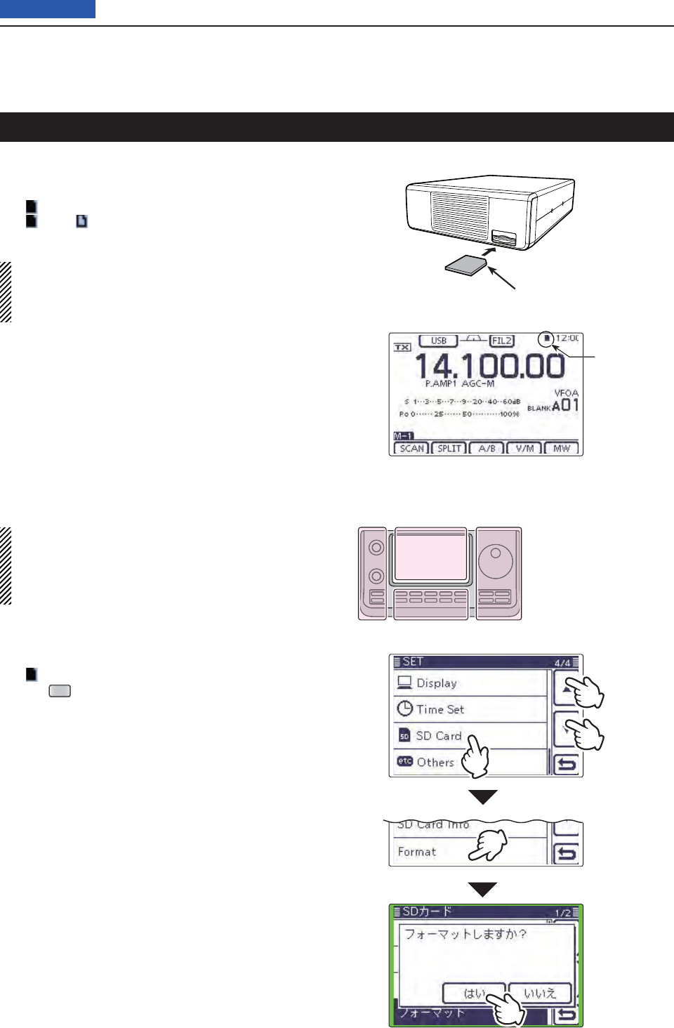
13 USING AN SD CARD
13-4
Previous view
Turn OFF the transceiver. q
Insert the card into the slot until it locks in place, and w
makes a ‘click’ sound.
• “ ” appears when the SD card is inserted.
• “” and “ ” alternately blink while accessing the SD
card.
NOTE: Before inserting, be sure to check the card
direction.
If the card is forcibly or inversely inserted, it will dam-
age the card and/or the slot.
Inserting the SD card
Terminals
facing down Cut corner side
Front
panel
SD card
Appears
●
w
q
q
Formatting the SD card D
• If you use a brand new SD card, format it, by doing
the following steps.
• Formatting a card erases all its data. Before for-
matting any programmed card, make a backup fi le
onto your PC.
Turn OFF the transceiver, and then insert the card q
into the slot.
Turn ON the transceiver. w
• “ ” appears when the SD card is inserted.
Push e
SET
(C) to enter the Set mode.
Touch the “SD Card” Set mode. r
• If the specifi ed item is not displayed, touch [∫] or [√](D)
one or more times to select the page.
Touch the “Format” item. t
• The confi rmation screen “Format OK?” appears.
Touch [YES]( yD).
• The formatting starts and the display shows the format-
ting progress.
• After formatting ends, the display automatically returns to
the screen displayed before touching [YES](D).
The L, R, C or D in the
instructions indicate the
part of the controller.
L: Left side
R: Right side
C: Center bottom
D: Display (Touch panel)
Left Right
Center
Display
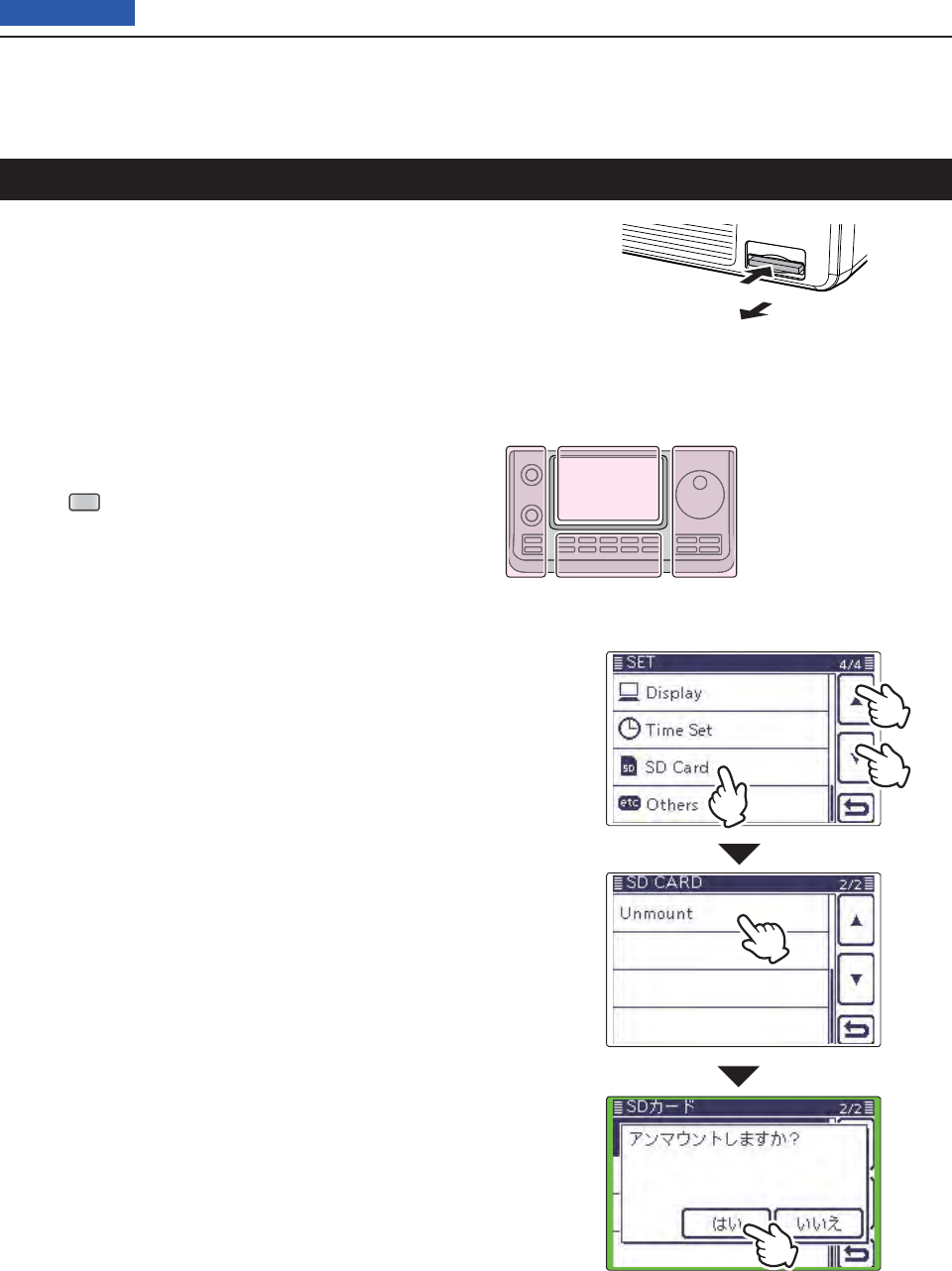
13 USING AN SD CARD
13-5
Previous view
Turn OFF the power. q
Push in the SD card until a click sounds, and then w
carefully pull it out.
Removing the SD card
Removing the SD card while the trans- D
ceiver’s power is ON
Push q
SET
(C) to enter the Set mode.
Touch the “SD Card” Set mode. w
• If the specifi ed item is not displayed, touch [∫] or [√](D)
one or more times to select the page.
Touch the “Unmount” item. e
• The confi rmation screen “Unmount OK?” appears.
Touch [YES]( rD).
• When the unmounting is completed, “Unmount is com-
pleted.” is displayed, then the display automatically re-
turns to the screen displayed before touching [YES](D).
Push in the SD card until a click sounds, and then t
carefully pull it out.
Push
Pull out
●
w
q
q
The L, R, C or D in the
instructions indicate the
part of the controller.
L: Left side
R: Right side
C: Center bottom
D: Display (Touch panel)
Left Right
Center
Display
Front
panel
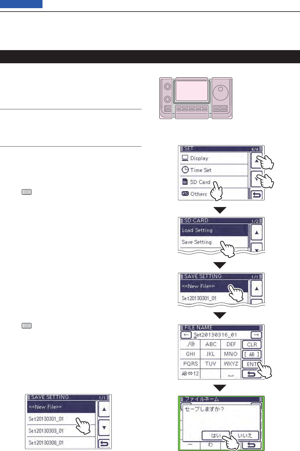
13 USING AN SD CARD
13-6
Previous view
Memory channels, Set mode item settings, and repeat-
er lists can be saved on the SD card.
Saving data settings on the SD card allows you to eas-
ily restore the transceiver to its previous settings, even
if an All reset is performed.
For your information ✓
Data settings are saved in the “icf” fi le format that is
used in the CS-7100 cloning software.
The saved data on the SD card can be copied onto a
PC and edited by the cloning software.
Data settings can be saved as a new fi le or to overwrite
an older fi le.
Saved as a new fi le
Push q
SET
(C) to enter the Set mode.
Touch the “Save Setting” item of the “SD Card” Set w
mode.
(SD Card > Save Setting)
• If the specifi ed item is not displayed, touch [∫] or [√](D)
one or more times to select the page.
Touch “<<New File>>.” e
• The “FILE NAME” screen appears.
• The fi le name is automatically named in the following
manner; Setyyyymmdd_xx (yyyy: Year, mm: month, dd:
day, xx: serial number)
Example: If a second fi le is saved on March 1, 2013, the
fi le is named “Set20130301_02.”
• If you want to change the fi le name, see “Save with a dif-
ferent fi le name” (p. ??-??).
Touch [ENT]( rD) to save the fi le name.
• The confi rmation screen “Save fi le?” appears.
Touch [YES]( tD) to save.
• While saving, a progress bar is displayed, then the “SD
CARD” screen is displayed after the save is completed.
Push y
SET
(C) to exit the Set mode.
Saving the setting data onto an SD card
●
w
q
q
The L, R, C or D in the
instructions indicate the
part of the controller.
L: Left side
R: Right side
C: Center bottom
D: Display (Touch panel)
Left Right
Center
Display
Overwriting a fi le
(Example: Overwriting the “Set20121210_01”)
➥Select the desired fi le to be overwritten in step e as
described on page ??-??.
(Example: Selecting “Set20121210_01”)
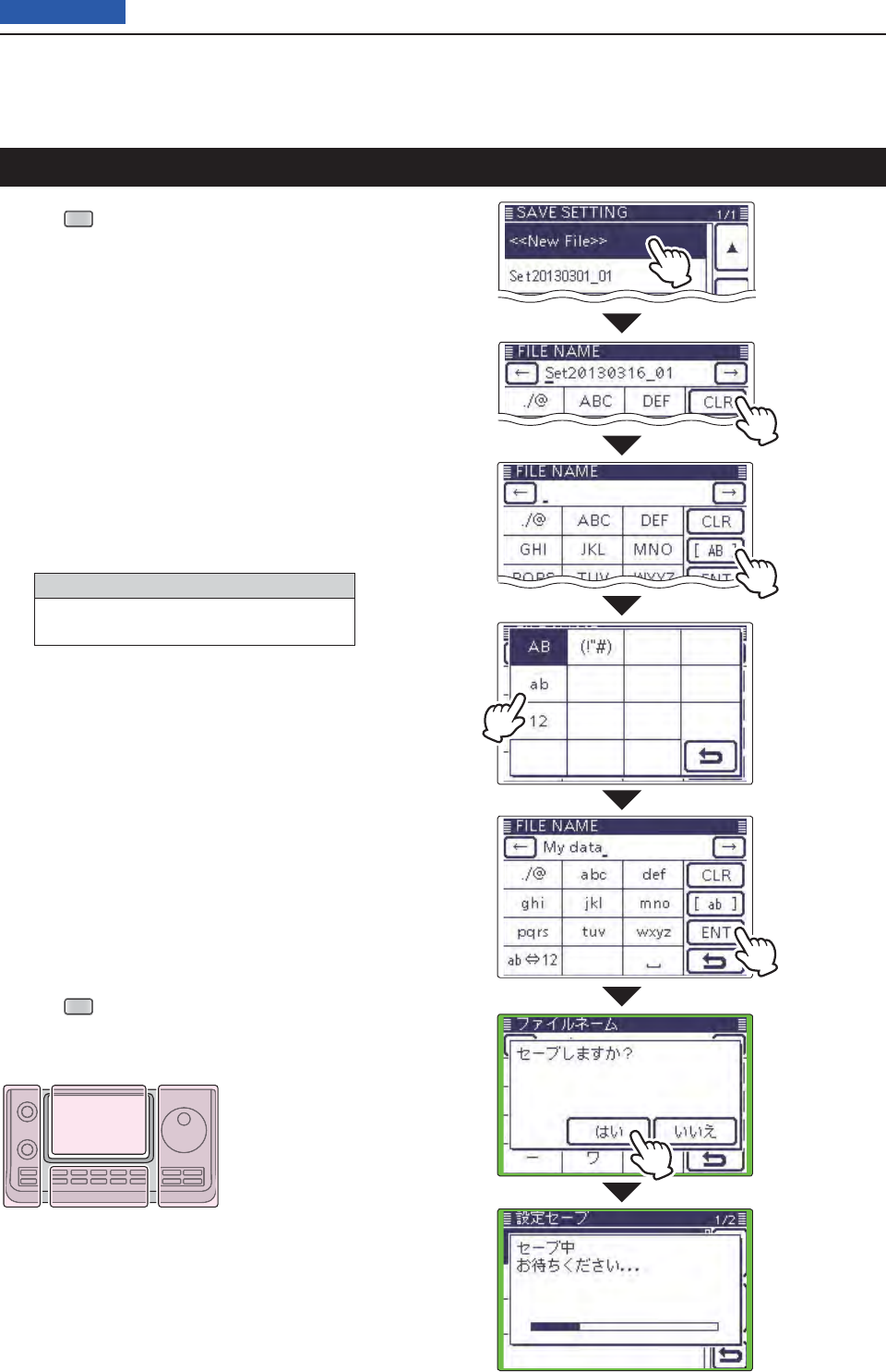
13 USING AN SD CARD
13-7
Previous view
Saving with a different fi le name
Push q
SET
(C) to enter the Set mode.
Touch the “Save Setting” item of the “SD Card” Set w
mode.
(SD Card > Save Setting)
• If the specifi ed item is not displayed, touch [∫] or [√](D)
one or more times to select the page.
Touch “<<New File>>.” e
• The “FILE NAME” screen appears.
Touch [CLR]( rD) to delete the previously programmed
character.
• Touch [CLR](D) to delete the selected character, symbol
or number.
When the cursor does not select a character, the previ-
ous character is deleted.
If [CLR](D) is continuously touched, all the characters
are deleted.
Touch the desired block one or more times to tselect
the desired character or symbol.
Selectable characters and symbols
A to Z, a to z, 0 to 9, ! # $ % & \ ? " ’ ` ^
+ – ✱ ⁄ . , : ; = < > ( ) [ ] { } ¦ _ ¯ @ (space)
• Touch “AB12” to toggle between the Alphabet input
and Number input mode.
• Touch [CLR](D) to delete the selected character, symbol
or number.
• Touch [SYMB](D) to open the Symbol character selec-
tion window.
• Touch “” to input a space.
Touch [ y](D) to move the cursor backwards, or
touch [](D) to move the cursor forwards.
Repeat steps ut and y to program up to 14 charac-
ters name.
• Example: MY DATA
Touch [ENT]( iD) to save the name.
• The confi rmation screen “Save fi le?” appears.
Touch [YES]( yD) to save.
• While saving, a progress bar is displayed, then the “SD
CARD” screen is displayed after the save is completed.
Push u
SET
(C) to exit the Set mode.
The L, R, C or D in the
instructions indicate the
part of the controller.
L: Left side
R: Right side
C: Center bottom
D: Display (Touch panel)
Left Right
Center
Display
Touch [!"#]
to open the
Symbol char-
acter selection
window.
After program-
ming, touch
[ENT]
In the
“Save Setting”
screen, touch
“<<New File>>”
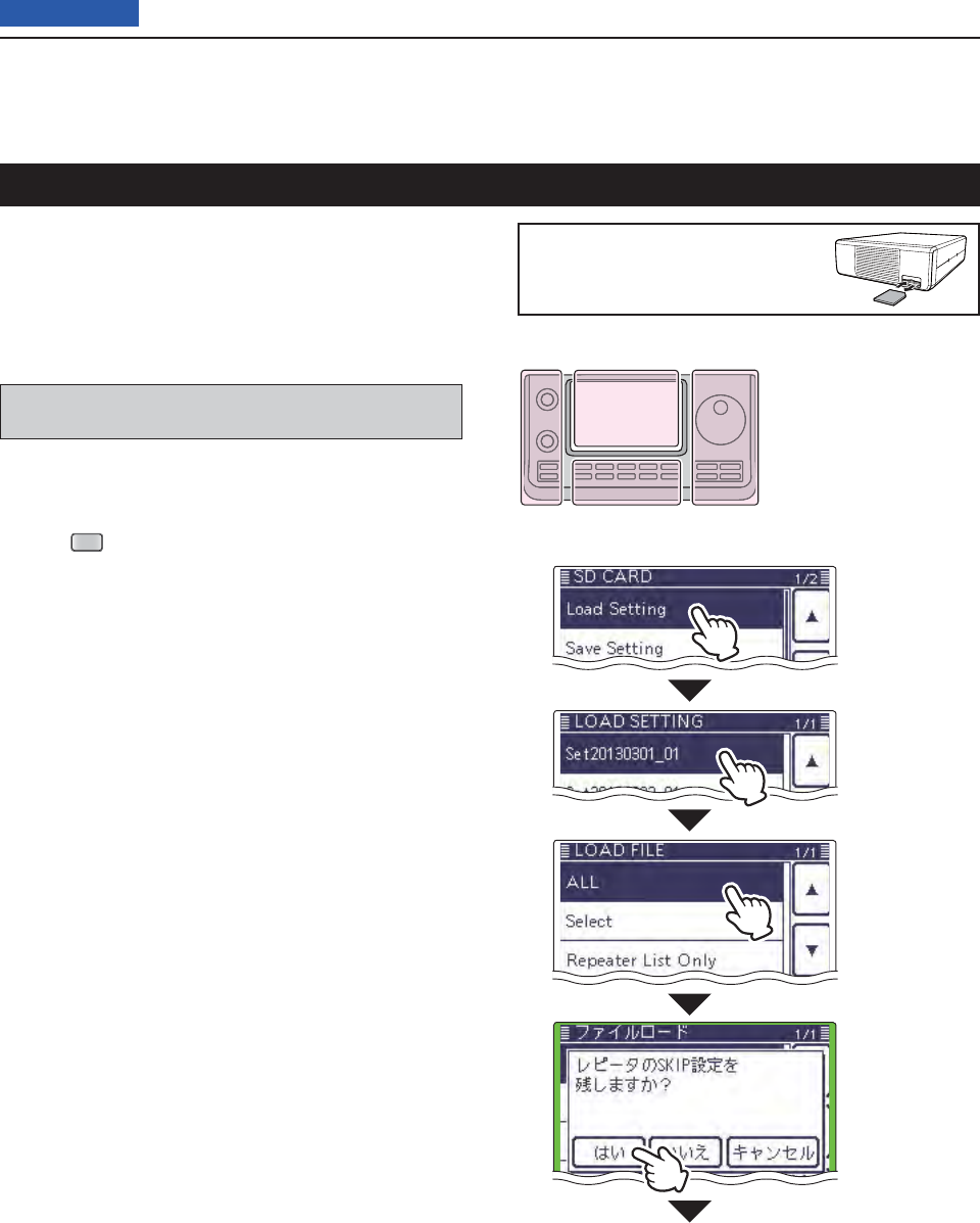
13 USING AN SD CARD
13-8
Previous view
The saved memory channels, Set mode item settings
and repeater lists can be copied to the transceiver.
This function is convenient when copying the saved
data, such as memory channels, or repeater lists, to
another IC-7100 and then operating with the same
data.
Saving the current data is recommended before load-
ing other data in the transceiver.
(Example: Loading all the data in the
“Set20130301_01” fi le)
Push q
SET
(C) to enter the Set mode.
Touch the “Load Setting” item of the “SD Card” Set w
mode.
(SD Card > Load Setting)
• If the specifi ed item is not displayed, touch [∫] or [√](D)
one or more times to select the page.
Touch the desired fi le to be loaded. e
(Example: Selecting “Set20130301_01”)
• The LOAD FILE screen appears.
Touch the desired loading roption, as shown below.
• ALL:
Loads all memory channels, item settings in the menu
list and the repeater list into the transceiver.
• Select:
Loads all memory channels, Set mode item settings
and the repeater list into the transceiver.
“MY call signs” and “REF Adjust” settings can be se-
lected to be loaded.
• Repeater List Only:
Loads only the repeater list into the transceiver.
The “Keep 'SKIP' settings in Repeater List?” appears. t
Touch [YES], [NO] or [Cancel](D).
• When [YES](D) is touched, the skip settings of the re-
peater list are retained. (p. ??-??)
• When [NO](D) is touched, the skip settings of the re-
peater list are not retained. (p. ??-??)
• When [Cancel](D) is touched, returns to the LOAD FILE
screen.
• When [YES] or [NO](D) is touched, “Load fi le?” ap-
pears.
To update the repeater list, click
here!
Loading the saved data fi les that are on the SD card
In the
“SD Card”
screen, touch
“Load Setting.”
The L, R, C or D in the
instructions indicate the
part of the controller.
L: Left side
R: Right side
C: Center bottom
D: Display (Touch panel)
Left Right
Center
Display
Continued on the next page ☞
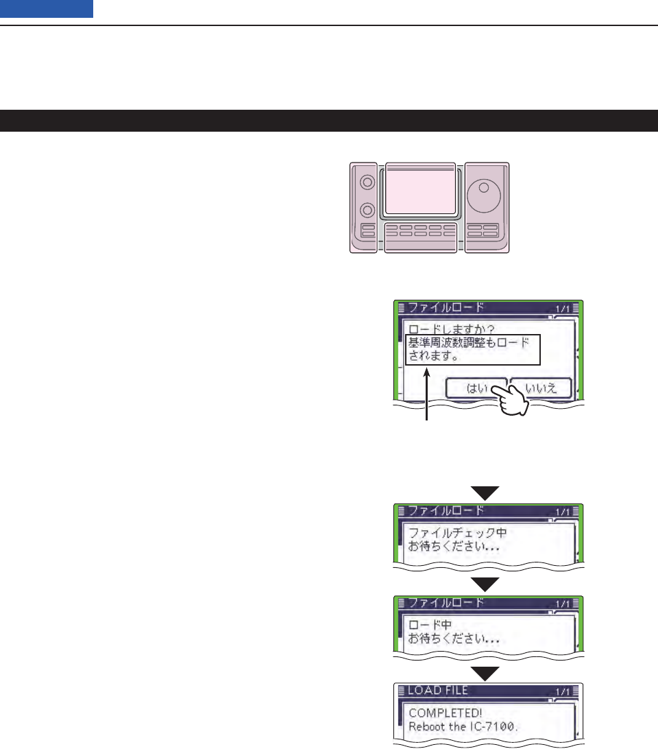
13 USING AN SD CARD
13-9
Previous view
Touch [YES]( yD) to start the fi le check.
• While checking the fi le, “CHECKING FILE” and a prog-
ress bar are displayed.
After checking, settings data loading ubegins.
• While loading, “LOADING” and a progress bar are dis-
played.
After loading iends, “COMPLETED!” appears.
To complete the loading, reboot the transceiver.
Loading the saved settings fi le that are on the SD card (Continued)
Appears only when “ALL” or “Select”*
is selected in the LOAD FILE screen,
* If “Select” is selected, only when the
“REF Adjust” check box is checked.
The L, R, C or D in the
instructions indicate the
part of the controller.
L: Left side
R: Right side
C: Center bottom
D: Display (Touch panel)
Left Right
Center
Display
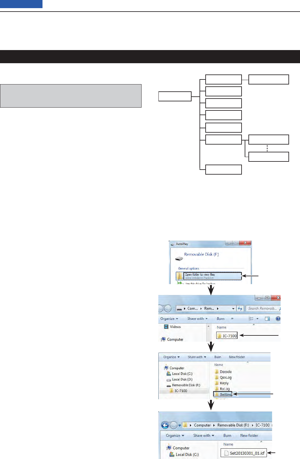
13 USING AN SD CARD
13-10
Previous view
A backup fi le allows easy restoring even if the setting
data in the SD card is accidentally deleted.
Depending on your PC, a memory card reader (pur-
chase locally) may be additionally required to read the
SD card.
About the SD card’s folder Dcontents
The folder in the SD card contains the following:
IC-7100 folder q
The folders created in the IC-7100 are contained in
this IC-7100 folder.
Decode folder w
The RTTY decode folder is created.
RTTY e folder
The transmitted or received RTTY decode data is
stored in the “txt” format.
The fi le format can be changed to “html” in the RTTY
DECODE LOG SET screen.
QSO r Log
QSO log data is stored in the “csv” format.
Reply folder t
Automatic reply data is stored in the “wav” format.
RxLog y
RX record log data is stored in the “csv” format.
Setting folder u
The transceiver’s setting data is stored in the “icf”
format.
Voice folder i
The recorded QSO audio date folders are created in
the Voice folder.
yyyymmdd folder o
Recorded audio fi le is stored in the “wav” format.
The folder name is automatically created in the fol-
lowing format:
yyyymmdd (yyyy:Year, mm:month, dd:day)
!0 VoiceTx
Recorded voice audio data for the Voice TX function
is stored in the “wav” format.
Click
Click
The setting
data
Click
(Example: Selecting the setting data)
When the SD card is inserted into the SD card drive of your
PC or the SD card reader (purchase locally), the screen ap-
pears as shown below.
IC-7100 q
Decode w
Reply t
Setting u
Voice iyyyymmdd o
yyyymmdd o
QsoLog r
RxLog y
!0 VoiceTx
Backing up the data stored on the SD card onto a PC
Rtty e
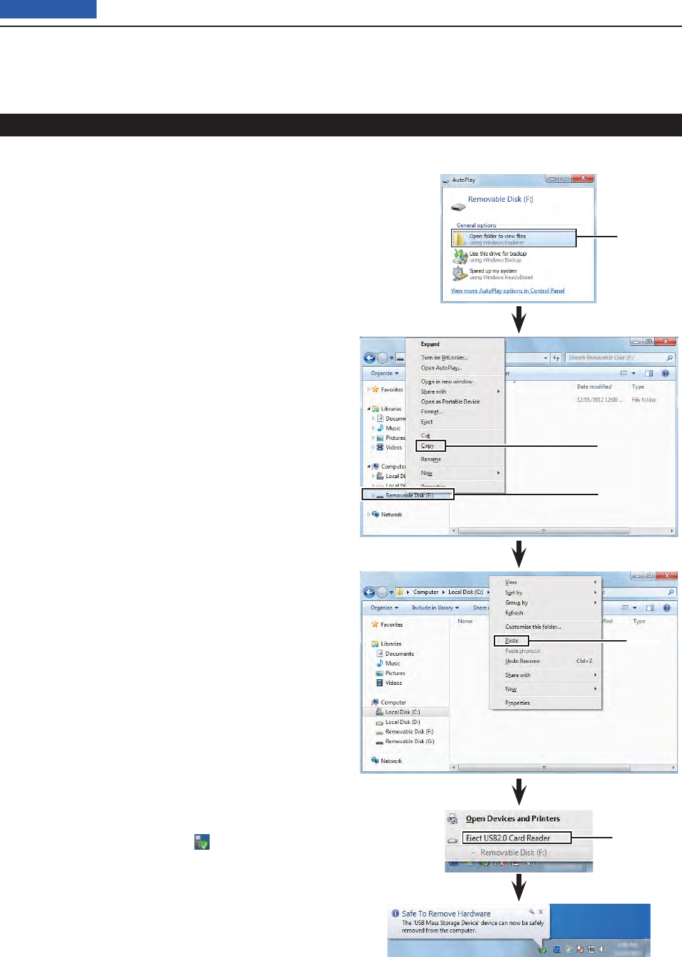
13 USING AN SD CARD
13-11
Previous view
Making a backup fi le on your PC D
Windows 7 is used for these instructions.
Insert the SD card into the SD card drive on your q
PC.
• If no SD card drive is built-in, connect a memory card
reader (purchase locally) and then insert the SD card into
it.
Click the “Open folder to view fi les” option to access w
the card.
Select “Removal disk” and right click. e
Click “Copy.” r
Open the desired folder to copy to, t then right click,
then click “Paste” to copy the data that is in the SD
card onto the hard disk.
(Example: Copying into the “Backup” folder in C
drive)
When removing the SD card from yyour PC, click the
SD card icon in the task bar. (“ ” icon in the screen
shot as shown to the right.)
• The screen shot shows when a memory card reader is
connected.
Remove the SD card from uyour PC when “Safe To
Remove Hardware” appears.
• The screen shot shows when a memory card reader is
connected.
Right click
Click
Click
Click
Click
Backing up the data stored on the SD card onto a PC (Continued)
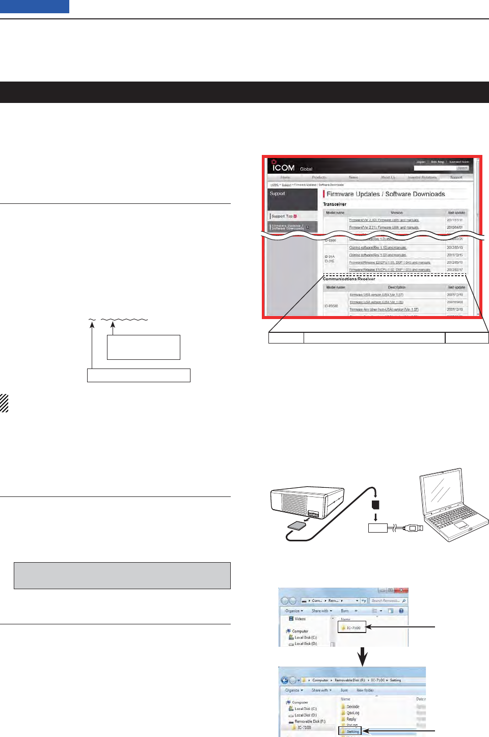
13 USING AN SD CARD
13-12
Previous view
For easy operation, the repeater list is preloaded into
your transceiver.
This section describes how to manually update the re-
peater list using an SD card.
The latest setting fi le, which includes the repeater list,
can be downloaded from the Icom website.
Downloading the latest setting fi le (ICF fi le)1.
q Access the following URL to download the latest
data.
http://www.icom.co.jp/world/support/download/fi rm/
index.html
• The latest settings fi le (ICF fi le) and repeater list (CSV;
Comma Separated Values fi le) are contained in the
downloaded ZIP fi le.
File Name: 7100_U_130301.zip
Depending on the
updated fi le date.
Depending on the version.
This instruction manual describes when the fi le name
is “7100_U_130301.zip,” for example.
w Decompress the compressed fi le that is downloaded
from the Icom website.
“7100_U_130301” folder will be created in the same
place where the downloaded file is saved.
Inserting the SD card into a PC2.
e Insert the SD card into the SD card drive on your
PC.
• Icom recommends that you format all SD cards to
be used with the IC-7100, even preformatted SD
cards for PCs or other uses.
See page ?-? for details of inserting and removing
the SD card.
Copying the latest ICF fi le to the SD card3.
r Double-click the “7100_U_130301” folder created in
the same place where the downloaded file is saved.
t Copy the ICF fi le (Example: “7100_USA_130301.
icf”) in the folder to the “Setting” folder in the “IC-
7100” folder of the SD card.
Continued on the next page ☞
Click
Click
IC-7100 Cloning software(Rev. MM) and manuals
2013/3/MM
IC-7100’s latest setting fi le is uploaded to
“Cloning software(Rev. MM) and manuals” in
the Icom website screen.
• The displayed contents may differ.
Updating the repeater list
SD card
Transceiver
to the Card
reader
PC
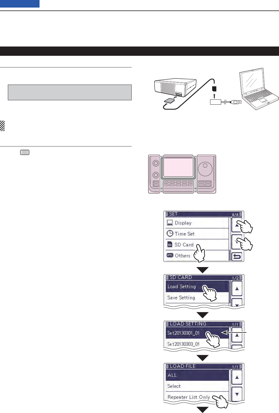
13 USING AN SD CARD
13-13
Previous view
Inserting the SD card4.
y Remove the SD card from your PC, and insert the
card into the transceiver’s slot.
See page ??-?? for details of inserting the SD card
into the transceiver.
Saving the current data is recommended before
loading other data into the transceiver.
Updating the repeater list5.
u Push
SET
(C) to enter the Set mode.
i Touch the “Load Setting” item of the “SD Card” Set
mode.
(SD Card > Load Setting)
• If the specifi ed item is not displayed, touch [∫] or [√](D)
one or more times to select the page.
o Touch the ICF fi le to be loaded.
(Example: Selecting “7100_USA_130301.icf”)
• The LOAD FILE screen appears.
!0 Touch “Repeater List Only.”
• The “Keep 'SKIP' settings in Repeater List?” appears.
• Loads only the repeater list into the transceiver.
Continued on the next page ☞
Updating the repeater list (Continued)
Select the fi le
to be loaded
●
w
q
q
SD card
Transceiver
from the Card
reader
PC
The L, R, C or D in the
instructions indicate the
part of the controller.
L: Left side
R: Right side
C: Center bottom
D: Display (Touch panel)
Left Right
Center
Display
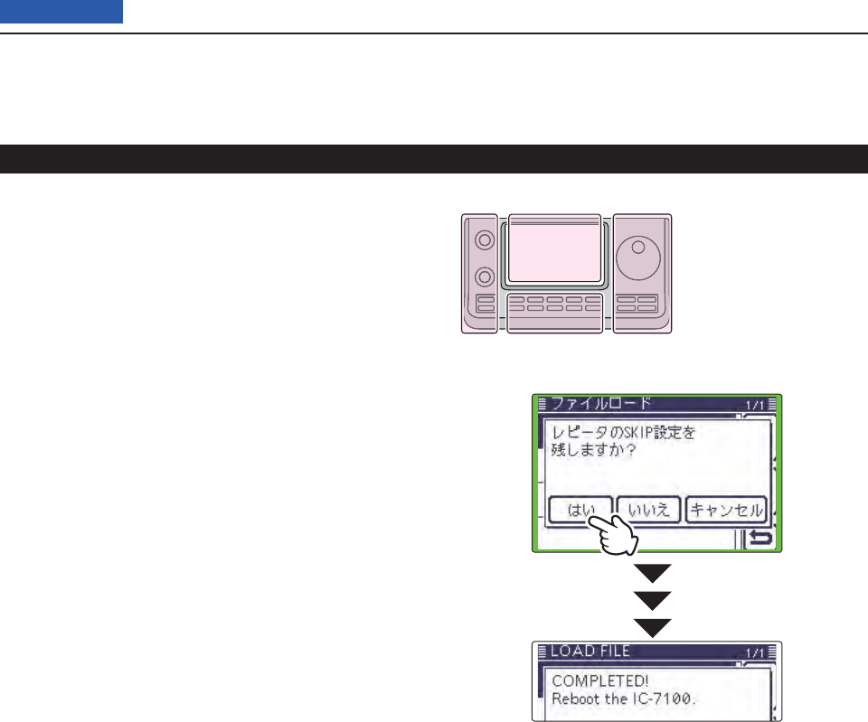
13 USING AN SD CARD
13-14
Previous view
!1 Touch [YES], [NO] or [Cancel](D).
• When [YES](D) is touched, the skip settings of the re-
peater list are retained. (p. ??-??)
• When [NO](D) is touched, the skip settings of the re-
peater list are not retained. (p. ??-??)
• When [Cancel](D) is touched, returns to the LOAD FILE
screen.
• When [YES] or [NO](D) is touched, “Load fi le?” ap-
pears.
!2 Touch [YES](D) to start the fi le check.
• While checking the fi le, “CHECKING FILE” and a prog-
ress bar are displayed.
!3 After checking, settings data loading begins.
• While loading, “LOADING” and a progress bar are dis-
played.
!4 After loading ends, “COMPLETED!” appears.
To complete the loading, reboot the transceiver.
Repeater list updating is complete!
Updating the repeater list (Continued)
The L, R, C or D in the
instructions indicate the
part of the controller.
L: Left side
R: Right side
C: Center bottom
D: Display (Touch panel)
Left Right
Center
Display
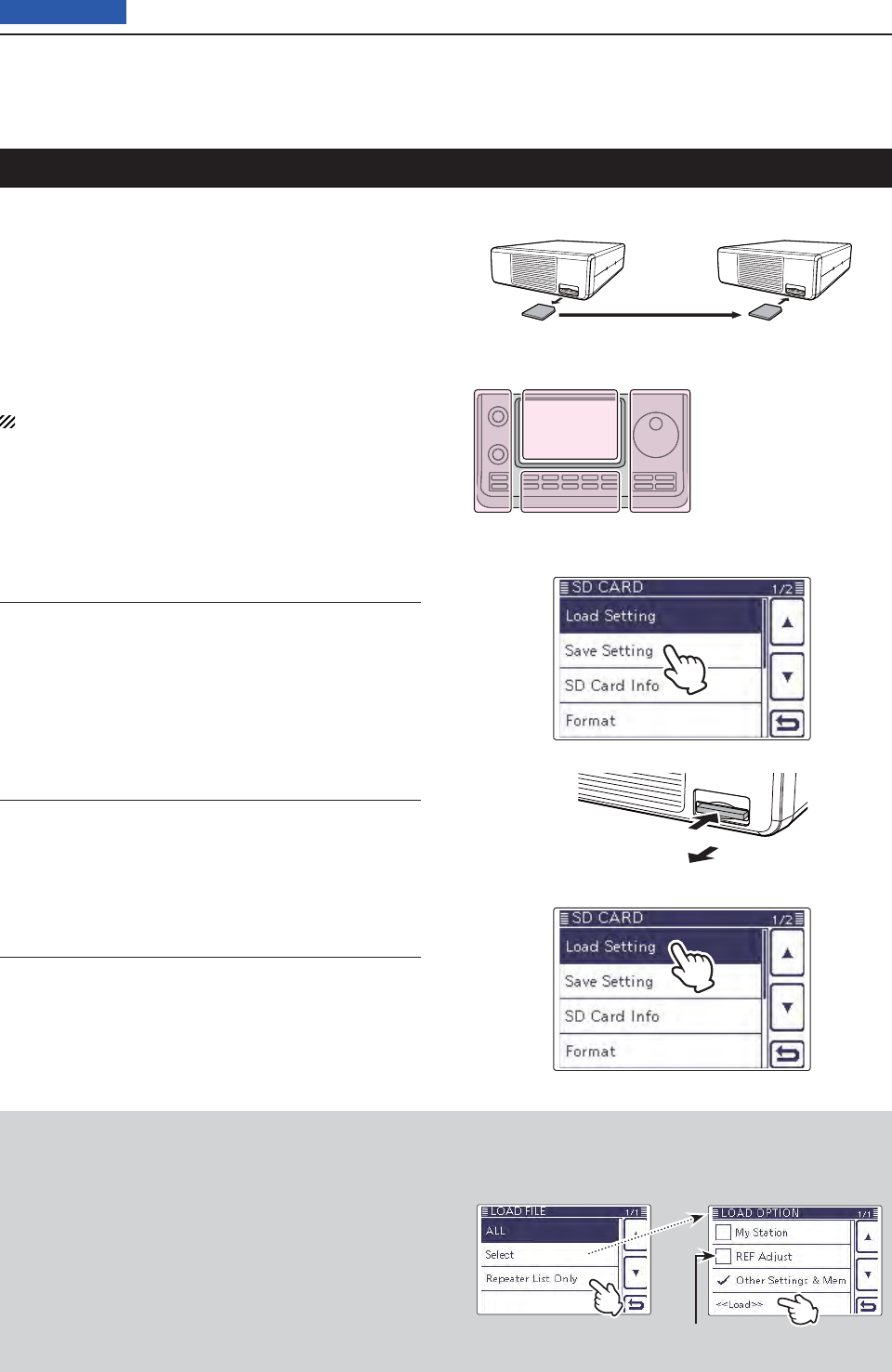
13 USING AN SD CARD
13-15
Previous view
Cloning Transceiver-to-Transceiver using an SD card
This topic describes the cloning method using the SD
card.
Memory channel contents, Set mode item settings and
repeater list can be saved onto a SD card.
Recorded voice memories are not included in the clon-
ing data. To play back the master transceiver’s voice
memory, insert the SD card into sub transceiver, or
make a copy onto the sub transceiver’s SD card using
a PC.
Description is with the SD card is already inserted.
Saving the master transceiver’s setting data onto 1.
the SD card.
q Save the master transceiver’s setting data onto the
SD card, as described on page ??.
Remove the SD card from the master transceiver, 2.
and then insert it to the sub transceiver.
w Turn OFF the master transceiver’s power.
e Remove the SD card from the master transceiver as
shown at right.
r Insert the removed SD card into the sub transceiver,
then turn ON the sub transceiver’s power.
Loads the setting data into the sub transceiver.3.
t The master transceiver’s setting data loads into the
sub transceiver, as described on page ??.
The L, R, C or D in the
instructions indicate the
part of the controller.
L: Left side
R: Right side
C: Center bottom
D: Display (Touch panel)
Left Right
Center
Display
SD card
Master transceiver Sub transceiver
Push
Pull out
Front
panel
When you load the data, be sure to set the loading
content as “Repeater List Only” or “Select” in the LOAD
FILE screen, and if “Select” is selected, the “REF Ad-
just” check box must be cleared.
Otherwise, it may result in a frequency deviation.
orLOAD FILE screen
Touch “Repeater List Only”
LOAD OPTIOIN screen
( Appears when “Select”
is touched in the LOAD
FILE screen)
Touch “Load” without check-
ing the “REF Adjust” box.

14-1
Section 14 VOICE MEMORY FUNCTION
Previous view
Recording a QSO audio ........................................................14-2
To start recording
D ..................................................................14-2
To stop recording
D ...................................................................14-2
Changing the recording mode .............................................14-3
Playing back the recorded audio .........................................14-4
Operation while playing back ...............................................14-5
Fast forward while playing
D .....................................................14-5
Rewind while playing
D .............................................................14-5
Pause while playing
D ...............................................................14-5
Playing the previous fi le
D.........................................................14-5
Playing the next fi le
D ...............................................................14-5
Moving to the beginning of the previous fi le
D ..........................14-5
Moving to the beginning of the next fi le
D .................................14-5
VOICE PLAYER screen
D’s descriptions ..................................14-5
Changing the skip time .........................................................14-6
Deleting the recorded contents (audio) ...............................14-7
Deleting the folder .................................................................14-8
Continue to record even if no signals are received ...........14-9
Record the transmit and receive audio into the same fi le .14-10
Start to record when the [PTT] switch is pushed ...............14-11
Viewing the folder information .............................................14-12
Viewing the fi le information ..................................................14-13
Viewing the SD card’s free space and recordable time .....14-15
Playing back the voice memory data on a PC ....................14-16
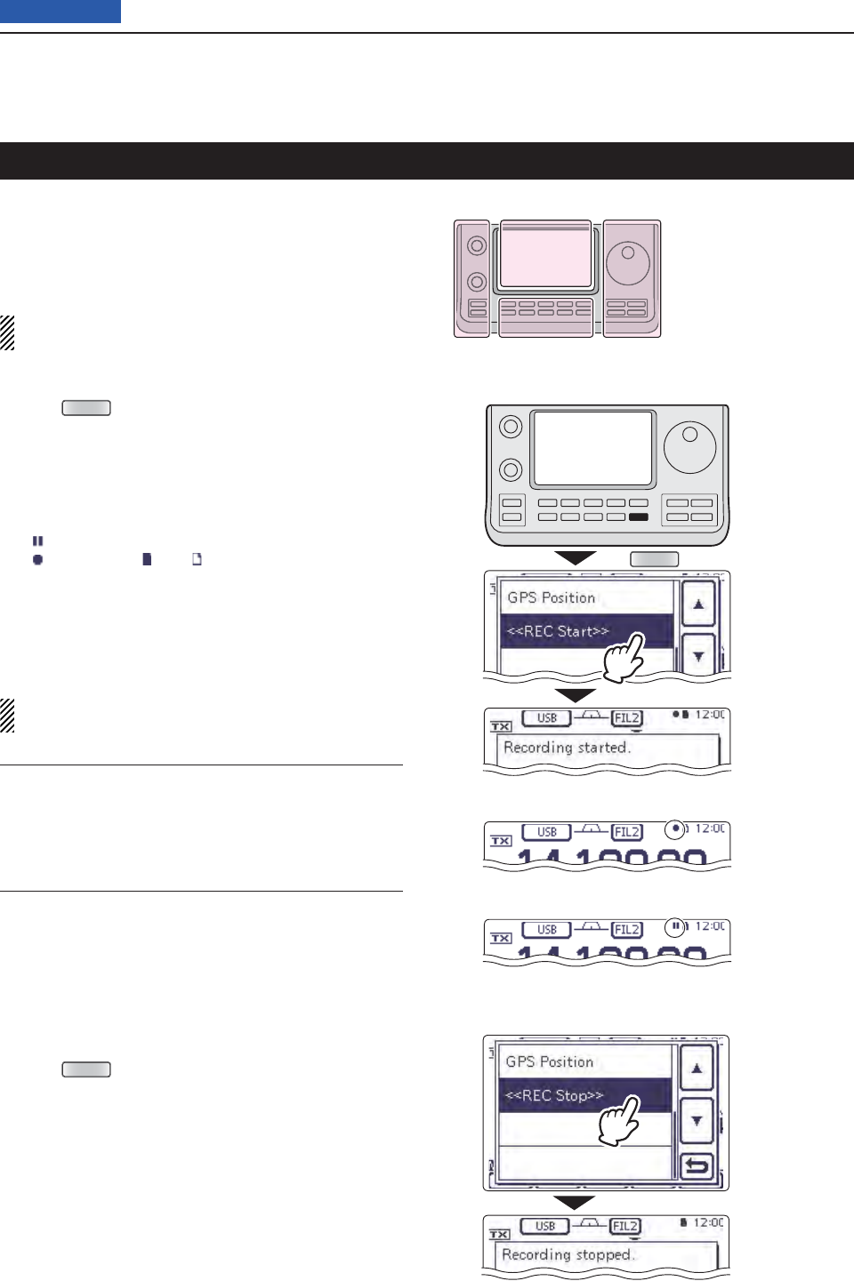
14 VOICE MEMORY FUNCTION
14-2
Previous view
The Voice Memory function records a QSO (communi-
cation) audio onto the SD card.
This function enables you to record both received and
transmitted audio, a QSO with a DX’pedition, and play-
back the recorded audio after the QSO.
NOTE: Be sure to insert an SD card into the trans-
ceiver before recording a QSO audio.
To start recording D
Push q
QUICK
(C) to open the Quick Menu screen.
Touch the “<<REC Start>>” item to start voice re- w
cording.
• Touch [√](D) one or more times to select the desired
page.
• The transceiver displays “Recording started” and auto-
matically exits the Quick Menu screen.
• “” appears while the recording is paused.
• “” appears and “ ” and “ ” alternately blink while record-
ing.
• Recording is continuous until you manually stop record-
ing, or the card becomes full.
• If the recording fi le’s content reaches 2GB, the transceiv-
er automatically creates a new fi le, and continues record-
ing.
NOTE: Once recording has started, it will continue,
even if the transceiver is rebooted.
Recording a QSO audio
QUICK
While recording
While pausing
Touch
“<<REC Start>>”
The L, R, C or D in the
instructions indicate the
part of the controller.
L: Left side
R: Right side
C: Center bottom
D: Display (Touch panel)
Left Right
Center
Display
Convenient! ✓
When the PTT Automatic Recording function is set to
ON, the recording automatically starts when [PTT] is
pushed. (p. ??-??)
( Voice Memo > QSO Recorder > Recorder Set >
PTT Auto REC)
To stop recording D
Push q
QUICK
(C) to open the Quick Menu screen.
Touch “<<REC Stop>>” to stop voice recording. w
• Touch [√](D) one or more times to select the desired
page.
• The transceiver displays “Recording stopped,” and auto-
matically exits the Quick Menu screen.
Touch
“<<REC Stop>>”
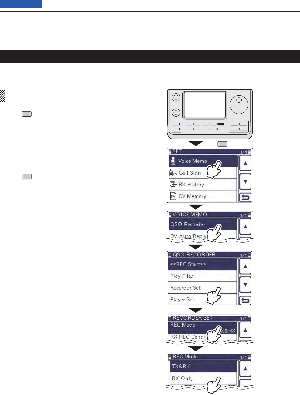
14 VOICE MEMORY FUNCTION
14-3
Previous view
You can change the recording mode in the Set mode to
record only the received audio.
The default setting is “TX&RX” (Both transmit and
receive signals are recorded).
Push q
SET
(C) to enter the Set mode.
Touch the “REC Mode” item of the “Voice Memo” Set w
mode.
( Voice Memo > QSO Recorder > Recorder Set >
REC Mode)
• If the specifi ed item is not displayed, touch [∫] or [√](D)
one or more times to select the page.
Touch “RX Only” to esave, and return to the previous
screen.
Push r
SET
(C) to exit the Set mode.
Changing the recording mode
SET
Touch
“Voice Memo.”
Touch
“Recorder Set.”
Touch
“REC Mode.”
Touch
“RX Only.”
Touch
“QSO Recorder.”
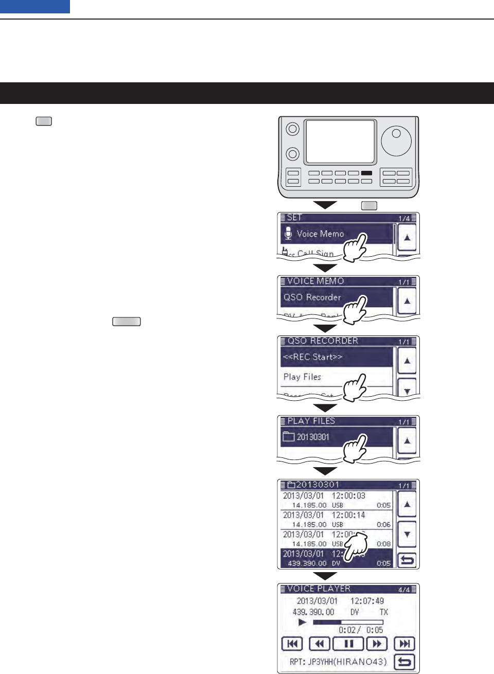
14 VOICE MEMORY FUNCTION
14-4
Previous view
Push q
SET
(C) to enter the Set mode.
Touch the “Play Files” item of the “Voice Memo” Set w
mode.
( Voice Memo > QSO Recorder > Play Files)
• If the specifi ed item is not displayed, touch [∫] or [√](D)
one or more times to select the page.
• The folder list is displayed. (The folders are automatically
made when the recording starts.)
• The folder name is formatted yyyymmdd (y: year, m:
month, d: day.)
Touch the folder that contains the fi le you want to e
play.
• The fi le list is displayed.
• The fi le name is formatted yyyy/mm/dd hh:mm:ss (y: year,
m: month, d: day, hh: hour, mm: minute, ss: second.)
Touch the fi le that you want to play. r
• The VOICE PLAYER screen is displayed, and the fi le
starts to playback.
Touch [ t](D) or push
MENU
(C) to stop the play-
back, and return to the fi le list screen.
Playing back the recorded audio
SET
Touch the fold-
er that contains
the fi le you want
to play.
Touch the fi le
that you want
to play.
Touch
“Voice Memo.”
Touch
“QSO Recorder.”
Touch
“Play Files.”
While playing back
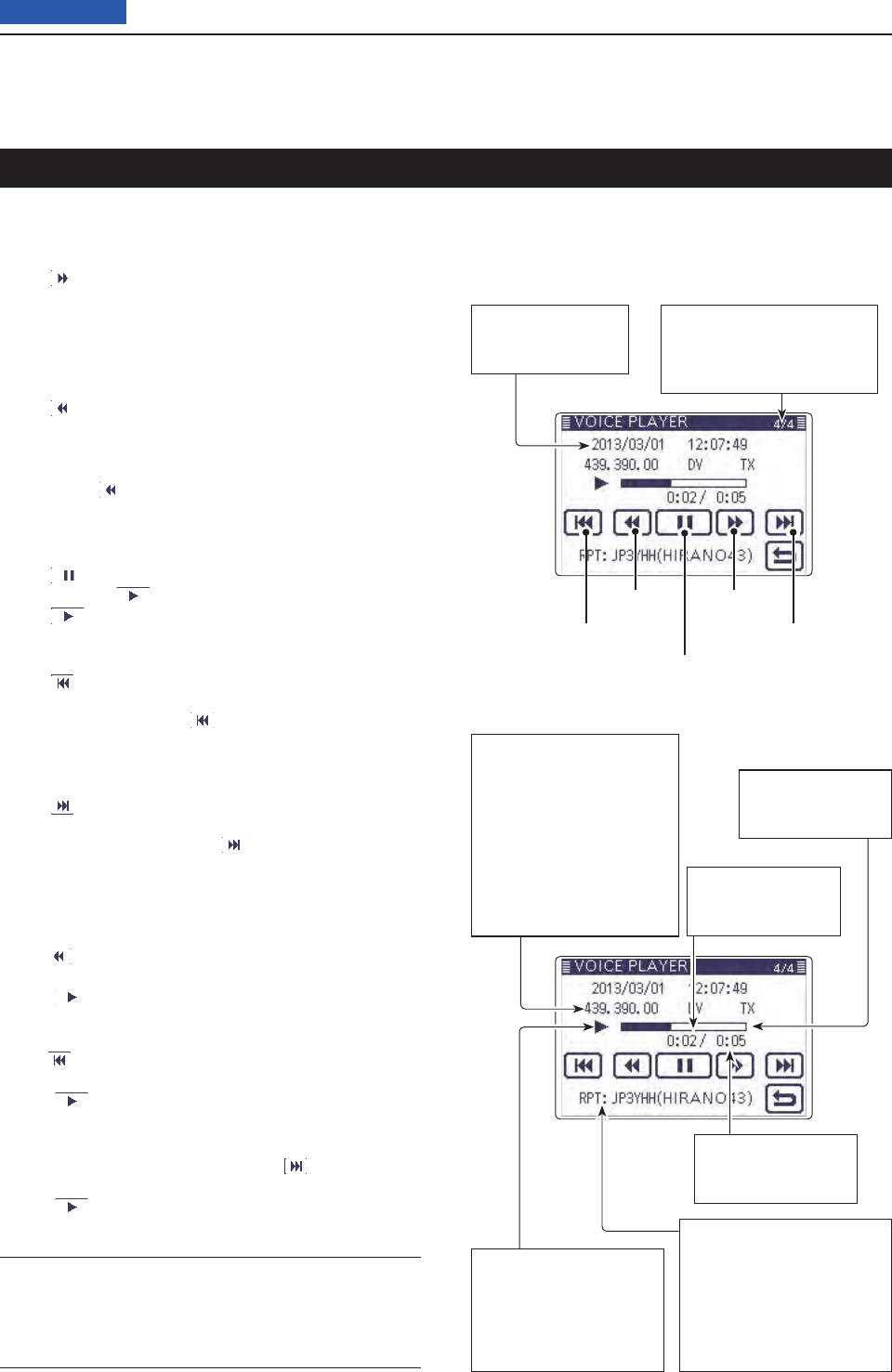
14 VOICE MEMORY FUNCTION
14-5
Previous view
You can fast forward or rewind while playing back.
Fast forward while playing D
Touch to fast forward to the skip time point.
(Default: 10 seconds)
If you want to change the skip time, see “Changing the
skip time.” (p. ??-??)
Rewind while playing D
Touch to rewind to the skip time point.
(Default: 10 seconds)
If you want to change the skip time, see “Changing the
skip time.” (p. ??-??)
• If you touch within the fi rst second of the fi le, the skip
time at the end of the previously recorded fi le will playback.
Pause while playing D
Touch to pause.
• While pausing, appears.
Touch to resume.
Playing the previous fi le D
Touch to play the previous fi le.
• In case there are other fi les in the folder, while the oldest
fi le is playing back, touch to start playing the beginning
of the fi le.
Playing the next fi le D
Touch to play the next fi le.
• In case there are other fi les in the folder, while the most re-
cent fi le is playing back, touch to stop the playback.
Moving to the beginning of the previous D
fi le
When the playback is paused anywhere within the fi le,
touch one or more times to return to the beginning
of the fi le, and pause.
• Touch to play it back.
When the playback is paused at beginning of a fi le,
touch to move to the beginning of the previous fi le,
and pause.
• Touch to play it back.
Moving to the beginning of the next fi le D
When the playback is paused, touch to move to the
beginning of the next fi le, and pause.
• Touch to play it back.
Operation while playing back
VOICE PLAYER screen D’s descriptions
The VOICE PLAYER screen is shown below.
Recording information
Shows the recorded fre-
quency, mode and audio
category.
• When the receive audio is
playing back, the audio cat-
egory is displayed as “RX.”
When the transmit audio is
playing back, the audio cat-
egory is displayed as “TX.”
Repeater call sign/name
Shows the repeater call
sign used in the DV mode.
When the repeater name
is programmed in your
repeater list, the name is
also displayed.
Pause or play
Rewind Fast forward
Play the next fi lePlay the previous fi le
File name
Shows the playback
fi le name.
File numbers
Shows the current playback
fi le and the total number of
fi les in the folder.
Progress bar
Shows the play
back progress bar.
Total time
Shows the fi le’s total
playback time.
Playback mark
Appears while the audio
is playing back.
• The mark disappears
while fast forwarding, re-
winding or pausing.
Played back time
Shows the played
back time.
Convenient! ✓
You can fast forward or rewind the fi le that is playing by
rotating the Dial.
The fast forward/rewind time is one twentieth of the to-
tal fi le time, regardless of the skip time setting.
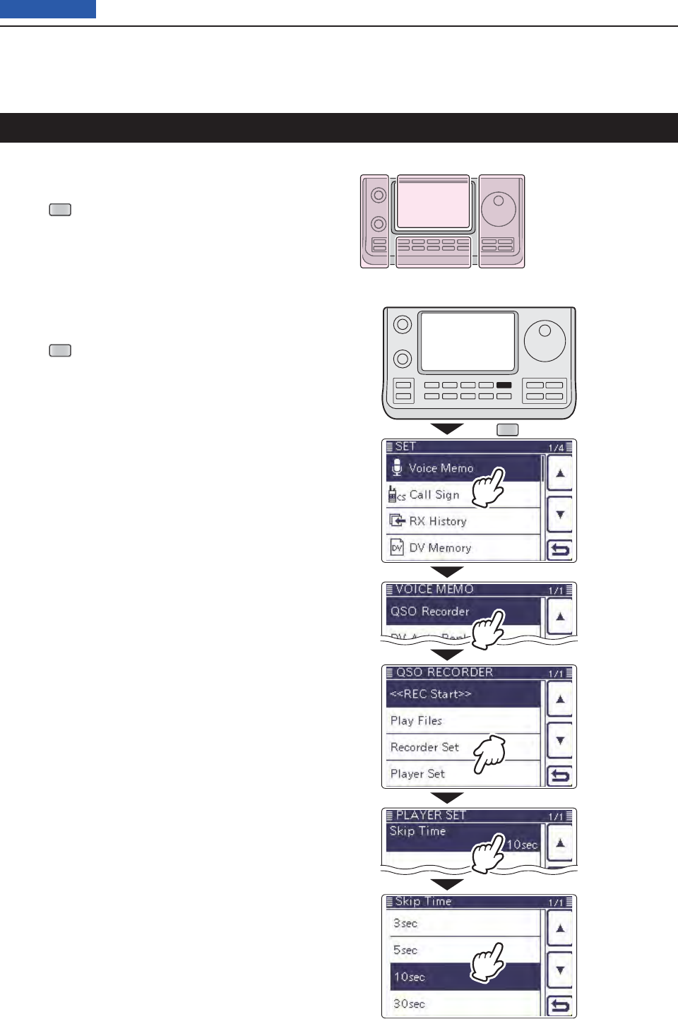
14 VOICE MEMORY FUNCTION
14-6
Previous view
You can change the fast forward and rewind skip time
while playing.
Push q
SET
(C) to enter the Set mode.
Touch the “Skip Time” item of the “Voice Memo” Set w
mode.
( Voice Memo > QSO Recorder > Player Set >
Skip Time)
• If the specifi ed item is not displayed, touch [∫] or [√](D)
one or more times to select the page.
Touch the desired skip time of 3, 5, 10 or 30 seconds e
to save, and return to the previous screen.
Push r
SET
(C) to exit the Menu screen.
Changing the skip time
SET
Touch
“Player Set.”
Touch
“Skip Time.”
(Example)
Touch “5sec.”
Touch
“Voice Memo.”
Touch
“QSO Recorder.”
The L, R, C or D in the
instructions indicate the
part of the controller.
L: Left side
R: Right side
C: Center bottom
D: Display (Touch panel)
Left Right
Center
Display
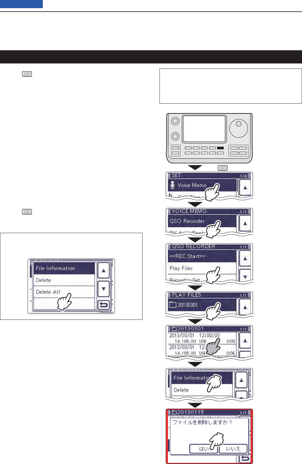
14 VOICE MEMORY FUNCTION
14-7
Previous view
Push q
SET
(C) to enter the Set mode.
Touch the “Play files” item of the “Voice Memo” Set w
mode.
( Voice Memo > QSO Recorder > Play files)
• If the specifi ed item is not displayed, touch [∫] or [√](D)
one or more times to select the page.
• The folder list is displayed. (The folders are automatically
made when recording starts.)
• The folder name is formatted yyyymmdd (y: year, m:
month, d: day.)
Touch the folder including the fi le that you want to e
delete.
• The fi le list is displayed.
• The fi le name is formatted yyyy/mm/dd hh:mm:ss (y: year,
m: month, d: day, hh: hour, mm: minute, ss: second.)
Touch the fi le that you want to delete for 1 second. r
Touch “Delete.” t
• The confi rmation screen “Delete fi le?” appears.
Touch “YES.” y
• The selected fi le is deleted.
Push u
SET
(C) to exit the Set mode.
<To delete all fi les>
When you want to erase all audio fi les in the folder at
one time, select “Delete All” in step t above.
Deleting the recorded contents (audio)
SET
Touch “Delete.”
Touch “YES.”
Touch the fi le that
you want to delete
for 1 second
Touch
“Play fi les.”
Touch the folder
including the fi le
that you want to
delete.
Touch
“Voice Memo.”
Touch
“QSO Recorder.”
The L, R, C or D in the instructions indicate the part of
the controller.
L: Left side, R: Right side, C: Center bottom
D: Display (Touch panel)
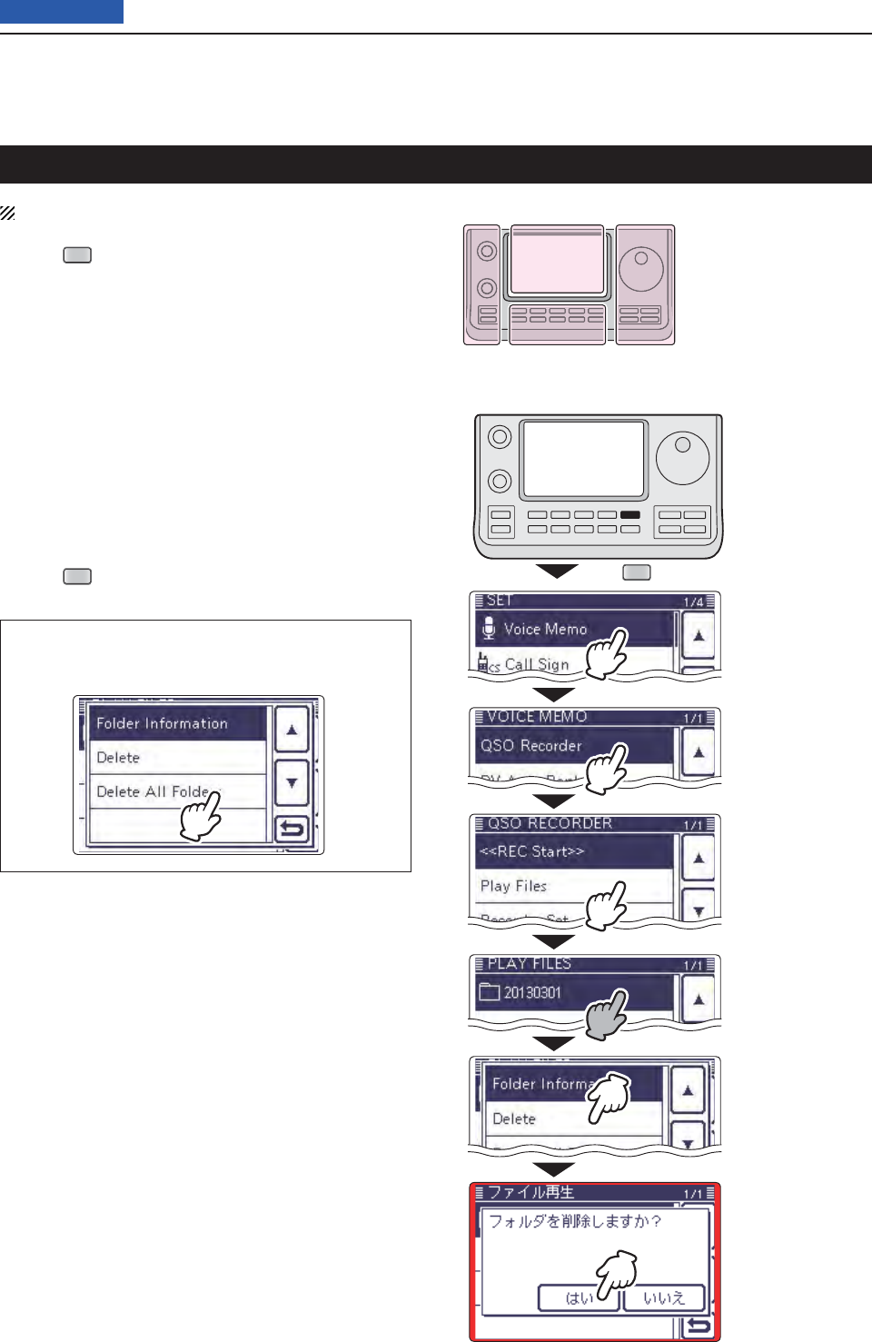
14 VOICE MEMORY FUNCTION
14-8
Previous view
NOTE: All the fi les in the folder are also deleted.
Push q
SET
(C) to enter the Set mode.
Touch the “Play files” item of the “Voice Memo” Set w
mode.
( Voice Memo > QSO Recorder > Play files)
• If the specifi ed item is not displayed, touch [∫] or [√](D)
one or more times to select the page.
• The folder list is displayed. (The folders are automatically
made when recording starts.)
• The folder name is formatted yyyymmdd (y: year, m:
month, d: day.)
Touch the folder that you want to delete for 1 sec- e
ond.
Touch “Delete.” r
• The confi rmation screen “Delete folder?” appears.
Touch “YES.” t
• The selected folder is deleted.
Push y
SET
(C) to exit the Set mode.
<To delete all folders>
When you want to erase all folders at one time, select
“Delete All Folders” in step r.
Deleting the folder
Touch “Delete.”
Touch “YES.”
Touch
“Play fi les.”
Touch the folder
that you want to
delete for 1 second
Touch
“Voice Memo.”
Touch
“QSO Recorder.”
The L, R, C or D in the
instructions indicate the
part of the controller.
L: Left side
R: Right side
C: Center bottom
D: Display (Touch panel)
Left Right
Center
Display
SET
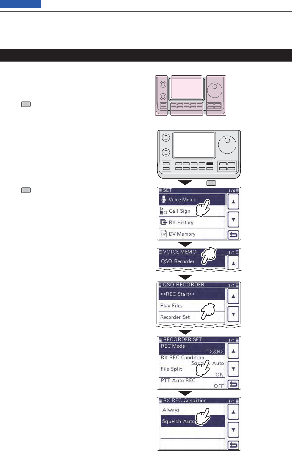
14 VOICE MEMORY FUNCTION
14-9
Previous view
In the default settings, the transceiver records audio
only while receiving signals (the squelch is open).
If you want to continue recording even if no signal is
received, do the following steps.
Push q
SET
(C) to enter the Set mode.
Touch the “RX REC Condition” item of the “Voice w
Memo” Set mode.
( Voice Memo > QSO Recorder > Recorder Set >
RX REC Condition)
• If the specifi ed item is not displayed, touch [∫] or [√](D)
one or more times to select the page.
Touch “Always” to continuously record even if no sig- e
nal is received.
• Always: Recording continues, even if no signals
are received.
• Squelch Auto: The transceiver records audio only while
receiving signals (the squelch opens).
Push r
SET
(C) to exit the Set mode.
Continue to record even if no signals are received
SET
Touch
“RX REC Condition.”
Touch
“Voice Memo.”
Touch
“QSO Recorder.”
(Example)
Touch “Always.”
The L, R, C or D in the
instructions indicate the
part of the controller.
L: Left side
R: Right side
C: Center bottom
D: Display (Touch panel)
Left Right
Center
Display
Touch
“Recorder Set.”
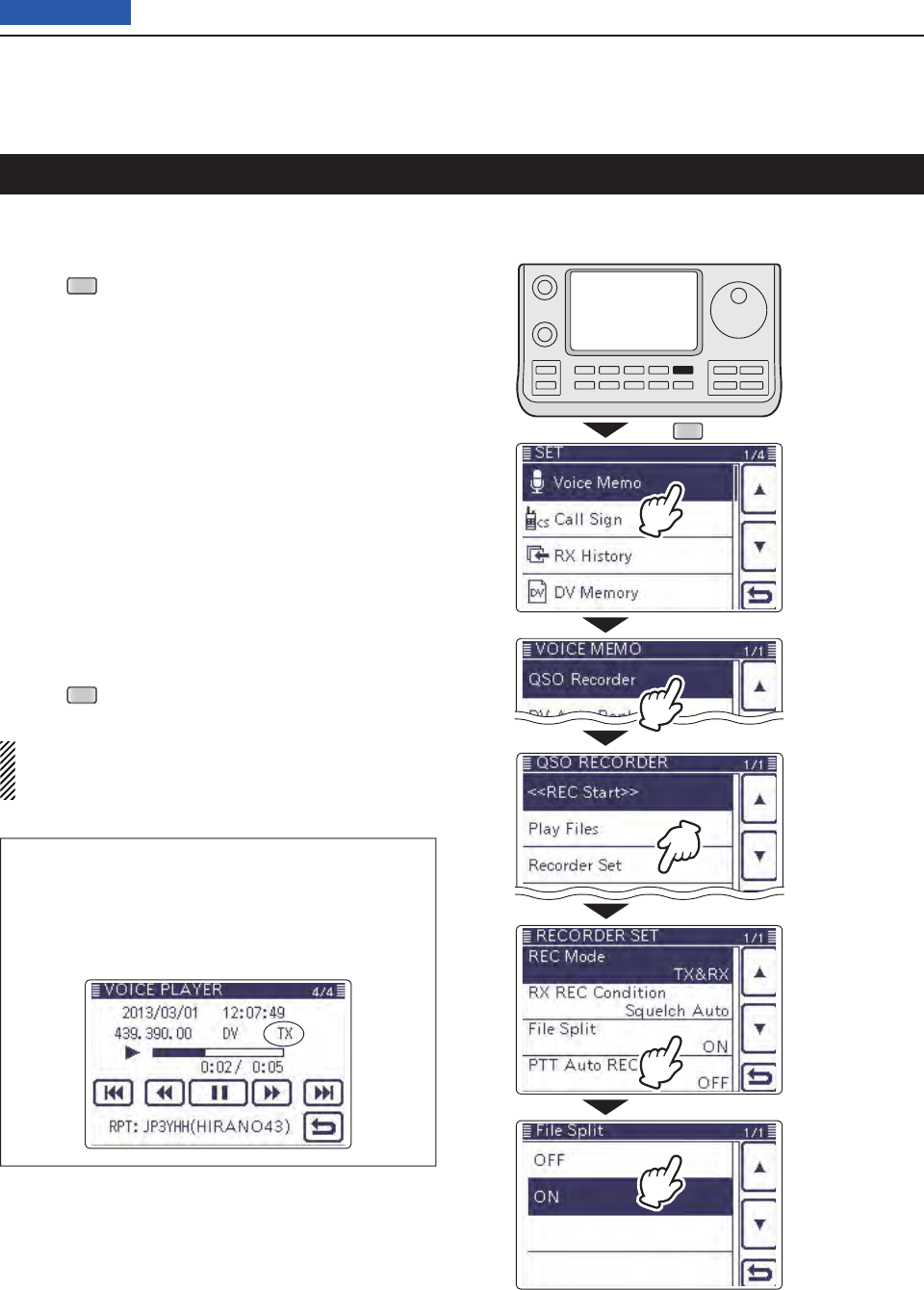
14 VOICE MEMORY FUNCTION
14-10
Previous view
The transceiver can record the transmit and receive au-
dio into the same fi le.
Push q
SET
(C) to enter the Set mode.
Touch the “File Split” item of the “Voice Memo” Set w
mode.
( Voice Memo > QSO Recorder > Recorder Set >
File Split)
• If the specifi ed item is not displayed, touch [∫] or [√](D)
one or more times to select the page.
Touch “OFF.” e
• OFF : The transceiver records the transmit and receive
audio into the same fi le.
• ON : The transceiver records the transmit and receive
audio into each fi le.
The transceiver makes separate new fi les for
transmit and receive audio. (Default setting)
• When you set the RX REC Condition item to
“Squelch Auto,” the transceiver records audio to
the new fi le when the squelch either opens or
closes.
( Voice Memo > QSO Recorder > Recorder set >
RX REC Condition)
Push r
SET
(C) to exit the Set mode.
NOTE: Even if you set the “File Split” item to OFF,
when the recording fi le’s content becomes 2 GB, the
transceiver continues to record, but to a new fi le.
About the VOICE PLAYER screen when recording
into the same fi le
The VOICE PLAYER screen shows information that
is recorded fi rst.
When the receive audio was recorded fi rst, the trans-
mit audio information is not displayed on the screen.
Record the transmit and receive audio into the same fi le
SET
Touch
“File Split.”
Touch
“Voice Memo.”
Touch
“QSO Recorder.”
Touch
“OFF.”
Touch
“Recorder Set.”
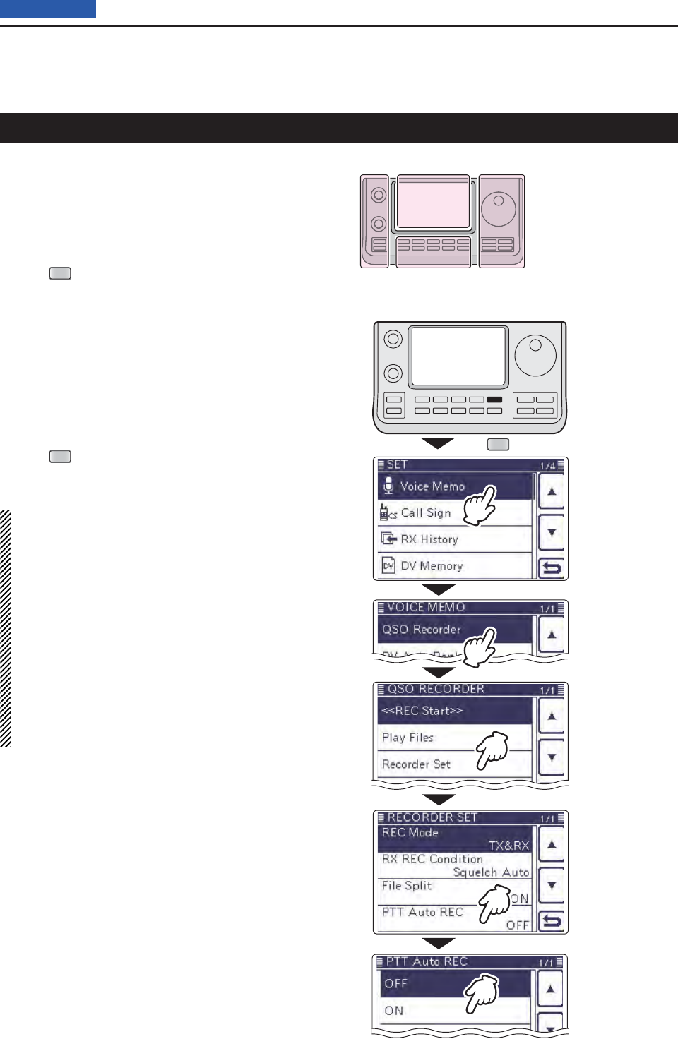
14 VOICE MEMORY FUNCTION
14-11
Previous view
The transceiver starts to record the transmitted audio
when the [PTT] switch is pushed.
After transmitting, when the transceiver receives a sig-
nal in a given amount of time, it also records the re-
ceived audio. Therefore, you can record all communica-
tion audio using this function.
Push q
SET
(C) to enter the Set mode.
Touch the “PTT Auto REC” item of the “Voice Memo” w
Set mode.
( Voice Memo > QSO Recorder > Recorder Set >
PTT Auto REC)
• If the specifi ed item is not displayed, touch [∫] or [√](D)
one or more times to select the page.
Touch “ON.” e
• OFF : The transceiver does not start to record when the
[PTT] switch is pushed.
• ON : The transceiver starts to record when the [PTT]
switch is pushed.
Push r
SET
(C) to exit the Set mode.
NOTE: When you set PTT AUTO REC to ON, see
the notes below.
• The transceiver also starts to record audio when
the optional microphone’s [PTT] switch is pushed,
transmitting using the VOX function or the CI-V re-
mote controller.
• All transmit audio is recorded.
( When “RX Only” is set in the “REC Mode” item,
transmit audio is not recorded)
• When the transceiver receives a signal less than
10 seconds after transmitting, the transceiver also
records the receive audio.
• In addition, when the transceiver receives a signal,
and then receives other signals less than 10 sec-
onds later, it records all signals audio.
Start to record when the [PTT] switch is pushed
SET
The L, R, C or D in the
instructions indicate the
part of the controller.
L: Left side
R: Right side
C: Center bottom
D: Display (Touch panel)
Left Right
Center
Display
Touch
“ON.”
Touch
“PTT Auto REC.”
Touch
“Voice Memo.”
Touch
“QSO Recorder.”
Touch
“Recorder Set.”
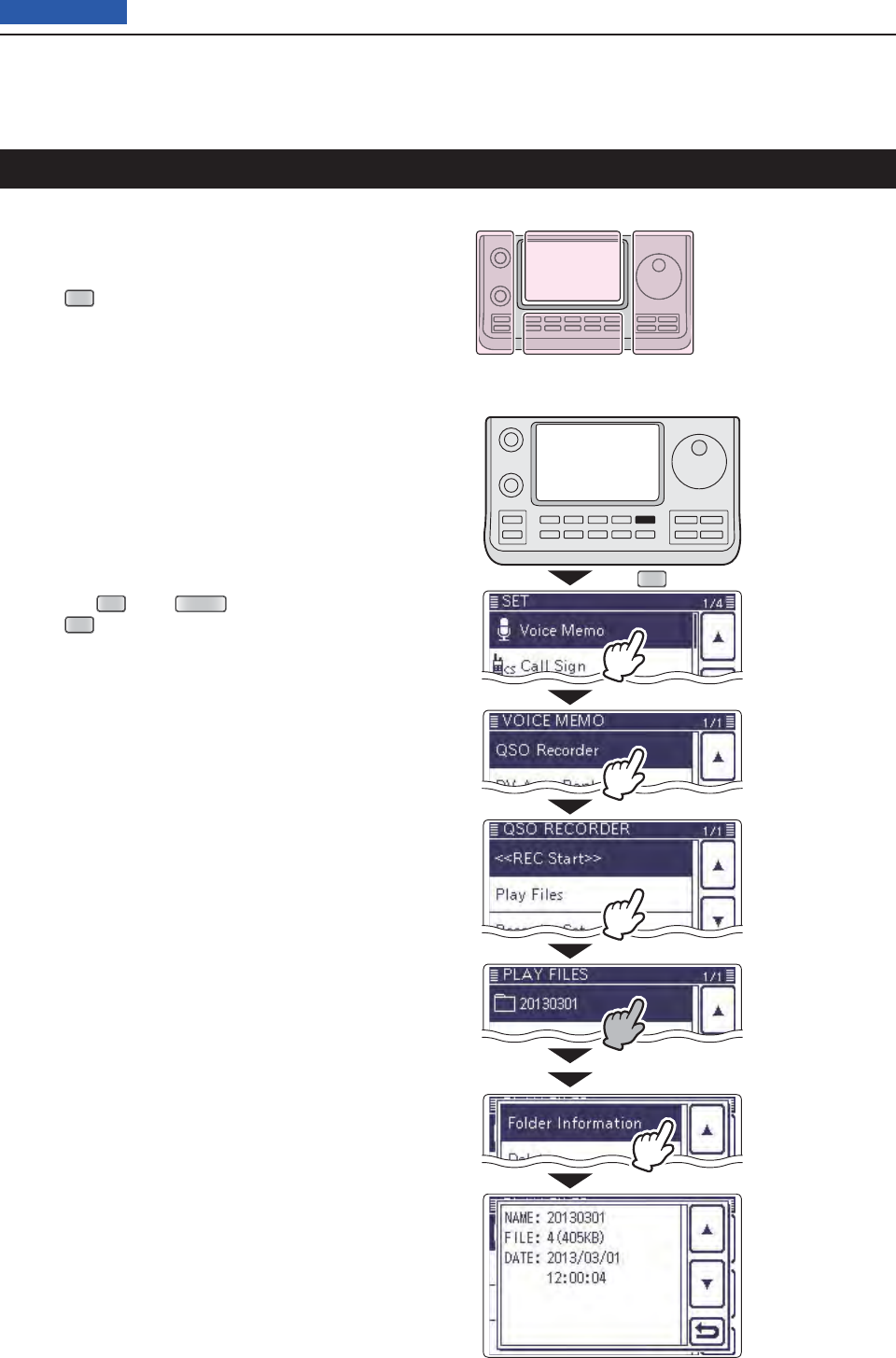
14 VOICE MEMORY FUNCTION
14-12
Previous view
The transceiver can display the folder’s name, number
of the fi les in the folder, total capacity of the fi les and
date.
Push q
SET
(C) to enter the Set mode.
Touch the “ w
Play Files
” item of the “Voice Memo” Set
mode.
( Voice Memo > QSO Recorder > Play Files)
• If the specifi ed item is not displayed, touch [∫] or [√](D)
one or more times to select the page.
• The folder list is displayed. (The folders are automatically
made when recording starts.)
• The folder name is formatted yyyymmdd (y: year, m:
month, d: day.)
Touch the folder that contains the fi le you want to e
view for 1 second.
Touch the “Folder Information” item. r
• The information screen appears.
Touch [ t](C) to cancel the information screen.
• Touching
SET
(C) or
QUICK
(C) also cancels.
Push y
SET
(C) to exit the Set mode.
Viewing the folder information
SET
Shows the information.
The L, R, C or D in the
instructions indicate the
part of the controller.
L: Left side
R: Right side
C: Center bottom
D: Display (Touch panel)
Left Right
Center
Display
Touch
“Play Files.”
Touch
“Voice Memo.”
Touch
“QSO Recorder.”
Touch the folder that
you want to view the
information
Touch
“Folder Information.”
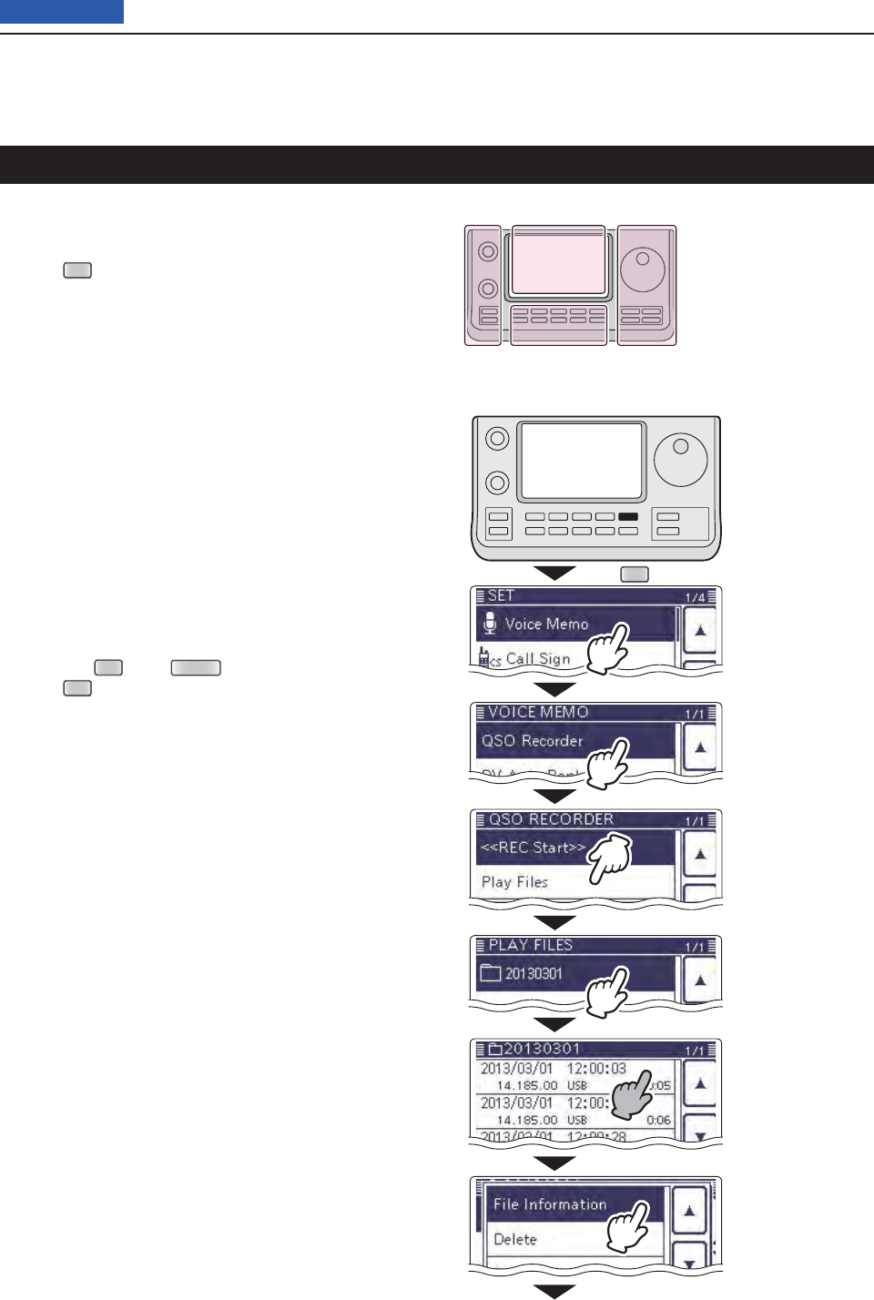
14 VOICE MEMORY FUNCTION
14-13
Previous view
The transceiver can display the recorded fi le’s frequen-
cy, mode, date, and so on.
Push q
SET
(C) to enter the Set mode.
Touch the “ w
Play Files
” item of the “Voice Memo” Set
mode.
( Voice Memo > QSO Recorder > Play Files)
• If the specifi ed item is not displayed, touch [∫] or [√](D)
one or more times to select the page.
• The folder list is displayed. (The folders are automatically
made when recording starts.)
• The folder name is formatted yyyymmdd (y: year, m:
month, d: day.)
Touch the folder that contains the fi le you want to e
view.
• The fi le list is displayed.
• The fi le name is formatted yyyy/mm/dd hh:mm:ss (y: year,
m: month, d: day, hh: hour, mm: minute, ss: second.)
Touch the fi le that you want to view the information r
for 1 second.
Touch the “File Information” item. t
• The information screen appears.
Touch [ y](C) to cancel the information screen.
• Touching
SET
(C) or
QUICK
(C) also cancels.
Push u
SET
(C) to exit the Set mode.
Viewing the fi le information
SET
Touch
“Play Files.”
Touch
“Voice Memo.”
Touch
“QSO Recorder.”
Touch the folder that
contains the fi le you
want to view.
Touch the file that
you want to view
the information for 1
second.
Touch
“File Information.”
The L, R, C or D in the
instructions indicate the
part of the controller.
L: Left side
R: Right side
C: Center bottom
D: Display (Touch panel)
Left Right
Center
Display
Continued on the next page. ☞
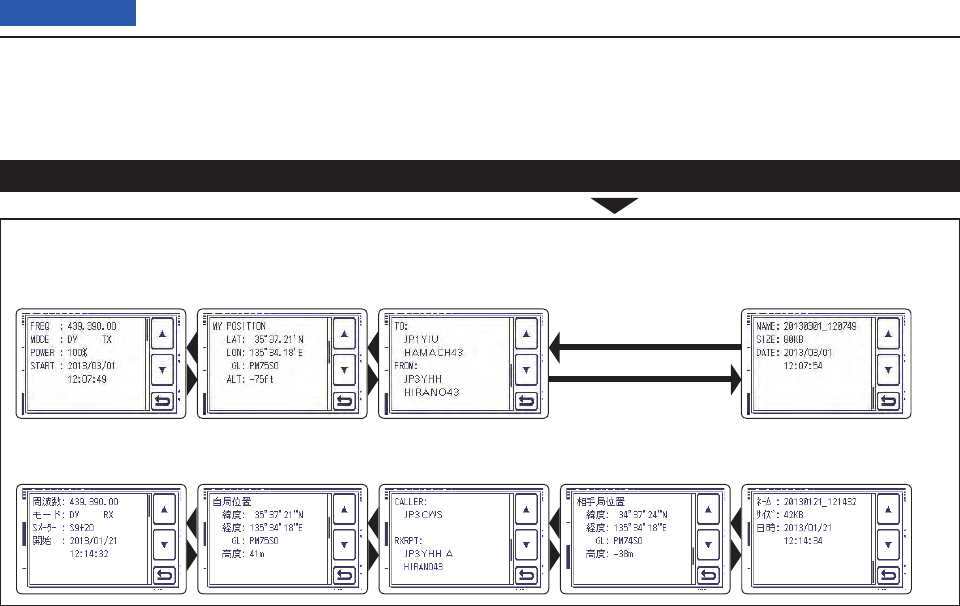
14 VOICE MEMORY FUNCTION
14-14
Previous view
Viewing the fi le information (Continued)
• Receive Information screen ( Receiving in the
DR mode)
Example of fi le information screens (The display items differ, depending on the recording contents.)
• Transmit Information screen
(Your own position)
( Transmitting in the
DR mode)
(Your own position) (Destination position)
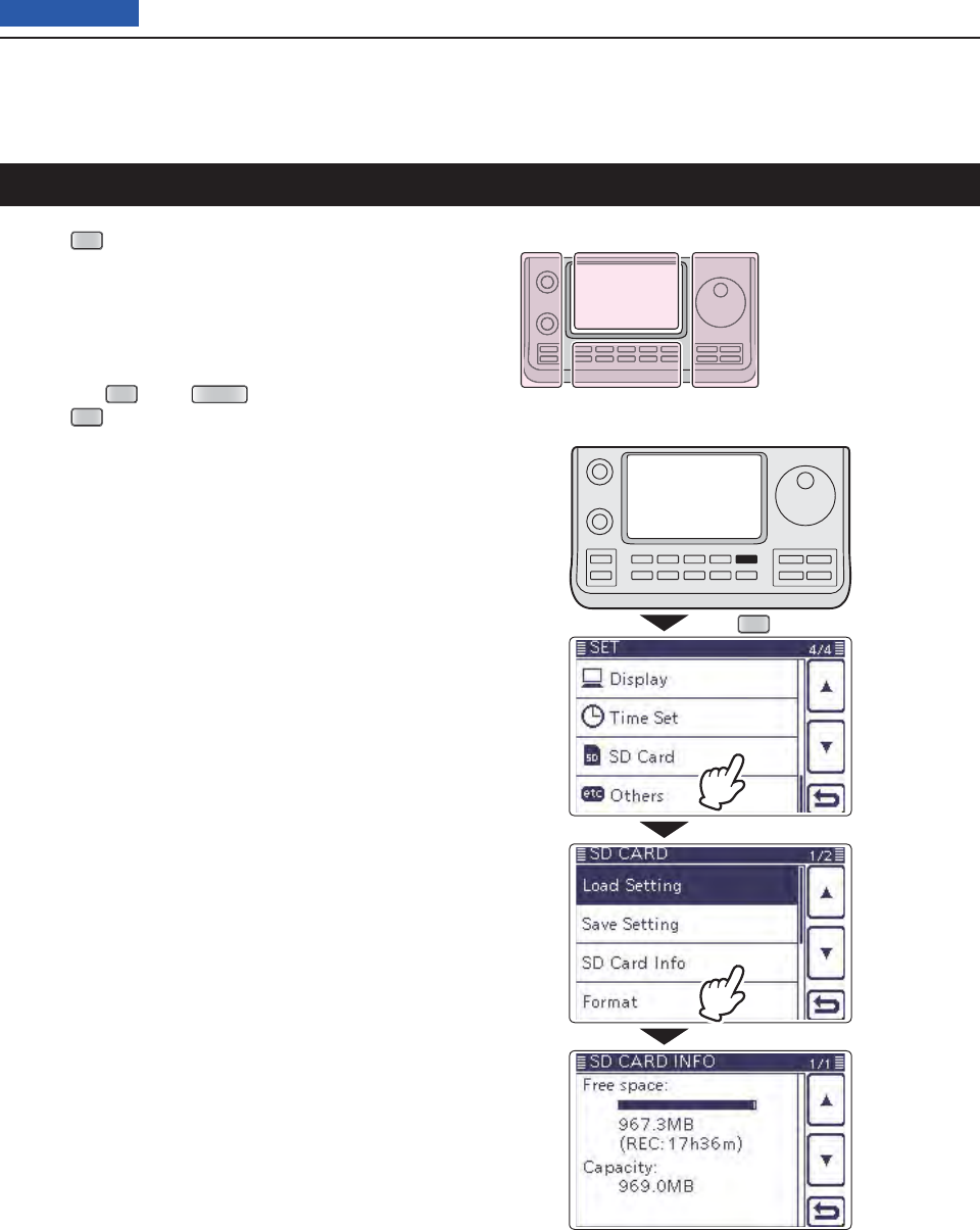
14 VOICE MEMORY FUNCTION
14-15
Previous view
Push q
SET
(C) to enter the Set mode.
Touch the “SD Card” item. w
• If the specifi ed item is not displayed, touch [∫] or [√](D)
one or more times to select the page.
Touch the “SD Card Info” item. e
• The information screen appears.
Touch [ r](C) to cancel the information screen.
• Touching
SET
(C) or
QUICK
(C) also cancels.
Push t
SET
(C) to exit the Set mode.
Viewing the SD card’s free space and recordable time
SET
Shows the information screen.
The L, R, C or D in the
instructions indicate the
part of the controller.
L: Left side
R: Right side
C: Center bottom
D: Display (Touch panel)
Left Right
Center
Display
Touch
“SD Card.”
Touch
“SD Card Info.”
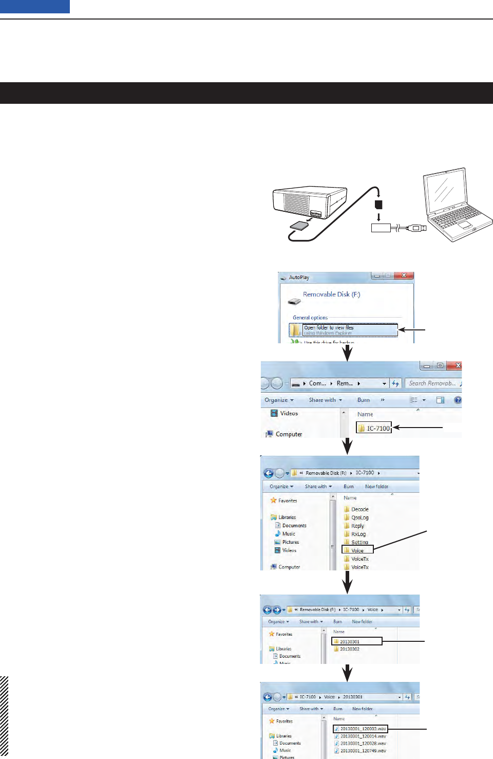
14 VOICE MEMORY FUNCTION
14-16
Previous view
You can also playback the voice memory data on a
PC.
However, the recorded information (frequency, date,
and so on) are not displayed.
• Mircosoft® Windows® 7 is used for the description.
Example: Connect a memory card reader (3rd party
product) to the PC, and insert the SD card
into the reader. Then playing back the voice
memory data in the card.
• When you copy the voice memory data from the
SD card to the PC’s hard disk drive, you also
operate the same as following steps for playing
back data.
Connect the memory card reader to the PC, and q
then insert the SD card into the reader.
• If your PC has an SD card drive, insert the card into the
drive.
When the SD card is inserted in the SD card drive of w
the PC or the SD card reader, the screen appears,
as shown to the right.
• The [IC-7100] folder appears.
Double-click the [IC-7100] folder. e
Double-click
Double-click
NOTE:
• The operations while playing back may differ, de-
pending on the software. Therefore, refer to the
software’s instruction manual for details.
• When the fi le does not playback, even if you dou-
ble-click the fi le, download appropriate software
like Windows Media® Player.
Double-click the [Voice] folder. r
Double-click the folder in which the fi le you want to t
playback is stored.
(Example: 20130301 folder)
To playback the fi le, double-click it. y
(Example: 20130301_184451.wav)
Click
Double-click
Double-click
Playing back the voice memory data on a PC
SD card
Transceiver
To the Card
reader
PC

15-1
Section 15 VOICE TX FUNCTION
Previous view
Recording the voice audio ....................................................15-2
Playing back the recorded voice audio ...............................15-3
Programming a memory name .............................................15-4
Transmitting the recorded voice audio ................................15-6
Adjusting the TX volume level
D ...............................................15-7
Voice TX Set mode .................................................................15-8
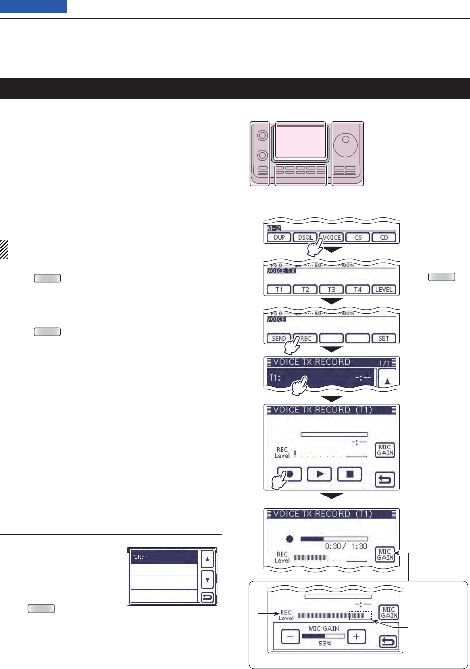
15 VOICE TX FUNCTION
15-2
Previous view
The Voice TX function transmits the recorded audio on
an SD card once, or repeatedly, for up to 10 minutes at
the specifi ed interval.
Up to 4 memories are available for repeated CQ and
exchange transmissions in contests, as well as when
making repeated calls to DX’peditions.
The recorded audio can be transmitted in the SSB, AM
(HF/50 MHz only), FM or DV mode.
The Voice TX function can be assigned to a key on the
optional HM-151 REMOTE CONTROL MIC or an external
keypad. (p. ??-??)
NOTE: Be sure to insert an SD card into the trans-
ceiver before recording a voice audio.
Push qMENU (C) one or more times to select the “M-
2” (Menu 2) screen.
• In the DR mode, select the “D1” screen.
Touch [VOICE]( wD) to select the Voice TX mode.
• The “VOICE TX” screen is displayed.
Push eMENU (C) to display the “VOICE” screen.
Touch [REC]( rD) to display the “VOICE TX RECORD”
screen.
Touch the desired memory, [T1] through [T4]. t
• The “VOICE TX RECORD (T1)” screen is displayed,
when [T1] memory is selected.
Touch [ y●](D) to start recording.
• Touch [■](D) to cancel recording.
• The maximum record time is 90 seconds.
• Hold the microphone 5 to 10 cm (2 to 4 inches) from your
mouth, then speak at a normal voice level.
• Touch [MIC GAIN](D) to display the “MIC GAIN” screen.
• If you record again on the same channel, the current con-
tents will be overwritten.
Touch [ u](C) to return to the “VOICE TX RECORD”
screen.
Information ✓
To delete the recorded au-
dio, touch the center of the
“VOICE TX RECORD (T1)”
through “VOICE TX RECORD
(T4)” screen for 1 second, or
push
QUICK
(C), and then
touch “Clear.”
Recording the voice audio
Touch
[VOICE]
Touch [REC]
(Example)
Touch [T1]
Push MENU
Touch [●]
The “MIC GAIN”
screen appears
after touching
Shows the audio input level.
While recording
Adjust so the
REC level bar
does not reach
this level.
The L, R, C or D in the
instructions indicate the
part of the controller.
L: Left side
R: Right side
C: Center bottom
D: Display (Touch panel)
Left Right
Center
Display
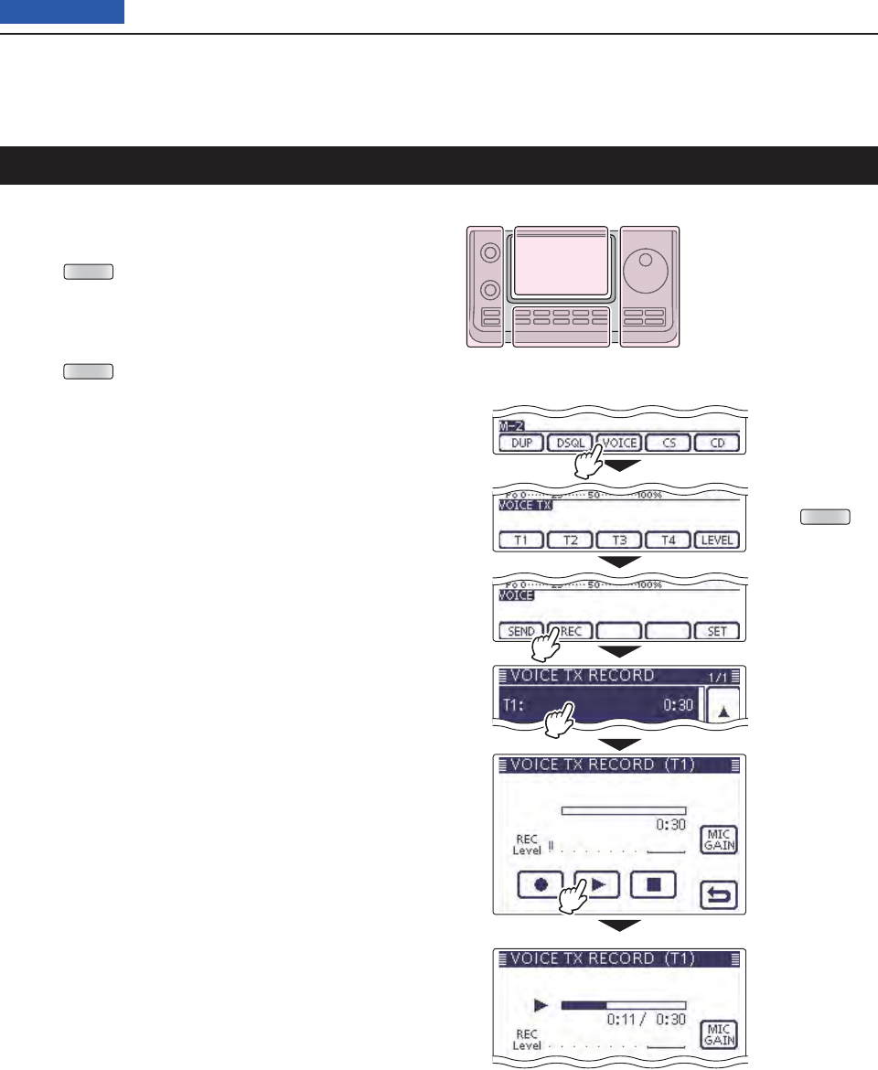
15 VOICE TX FUNCTION
15-3
Previous view
Playing back the recorded voice audio
The recorded voice audio for the Voice TX function can
be played back.
Push qMENU (C) one or more times to select the “M-
2” (Menu 2) screen.
• In the DR mode, select the “D1” screen.
Touch [VOICE]( wD) to select the Voice TX mode.
• The “VOICE TX” screen is displayed.
Push eMENU (C) to display the “VOICE” screen.
Touch [REC]( rD) to display the “VOICE TX RECORD”
screen.
Touch the desired memory, [T1] through [T4]. t
• The “VOICE TX RECORD (T1)” screen is displayed,
when [T1] memory is selected.
Touch [ y≈](D) to start the playback.
• Touch [■](D) to stop the playback.
Touch [ u](C) to return to the “VOICE TX RECORD”
screen.
Touch
[VOICE]
Touch [REC]
(Example)
Touch [T1]
Push MENU
Touch [≈]
While playing
The L, R, C or D in the
instructions indicate the
part of the controller.
L: Left side
R: Right side
C: Center bottom
D: Display (Touch panel)
Left Right
Center
Display
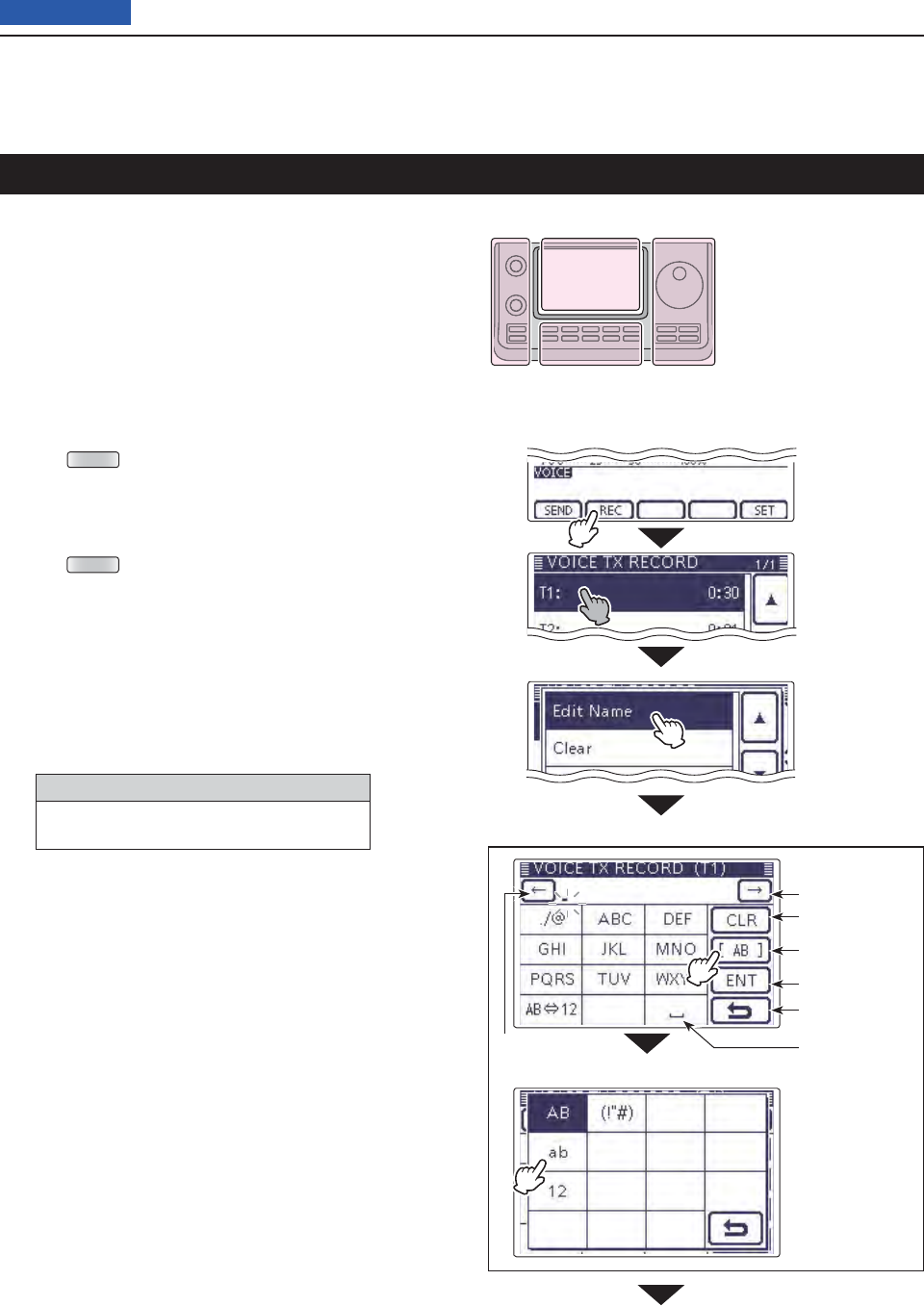
15 VOICE TX FUNCTION
15-4
Previous view
Each Voice TX memory, [T1] through [T4], can be pro-
grammed with an alphanumeric name of up to 16 char-
acters.
[EXAMPLE]: Programming the memory name “Con-
test” in [T1].
Push qMENU (C) one or more times to select the “M-
2” (Menu 2) screen.
• In the DR mode, select the “D1” screen.
Touch [VOICE]( wD) to select the Voice TX mode.
• “VOICE TX” screen is displayed.
Push eMENU (C) to display the “VOICE” screen.
Touch [REC]( rD) to display the “VOICE TX RECORD”
screen.
Touch the desired memory, [T1] through [T4], tfor 1
second to program.
Touch [Edit Name] to display the “VOICE TX RE- y
CORD (T1)” screen (Voice TX name edit screen).
• A cursor appears and blinks.
Touch the desired block one or more times to uselect
the desired character or symbol.
Selectable characters and symbols
A to Z, a to z, 0 to 9, ! # $ % & \ ? " ’ ` ^
+ – ✱ ⁄ . , : ; = < > ( ) [ ] { } ¦ _ ¯ @ (space)
• Touch “AB12” to toggle between the Alphabet input
and Number input mode.
• Touch [CLR](D) to delete the selected character, symbol
or number.
• Touch [SYMB](D) to open the Symbol character selec-
tion window.
• Touch “” to input a space.
Programming a memory name
Touch
[Edit Name].
Touch [REC]
(Example)
Touch [T1] for
1 second.
Continued on the next page. ☞
The L, R, C or D in the
instructions indicate the
part of the controller.
L: Left side
R: Right side
C: Center bottom
D: Display (Touch panel)
Left Right
Center
Display
Input a space
Move the cursor
Delete a character
Select an
input mode
Enter
Cancel edit
Move the cursor
Input mode screen
Touch [!"#] to
open the Symbol
character selec-
tion window.
Memory name edit screen
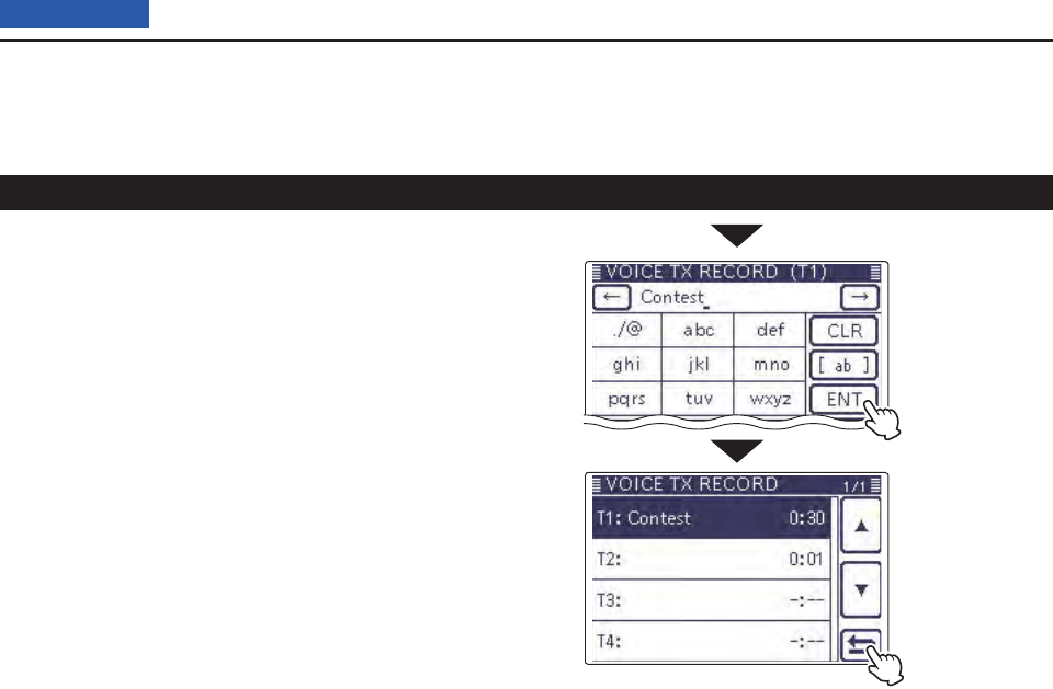
15 VOICE TX FUNCTION
15-5
Previous view
Programming a memory name (Continued)
After programming,
touch [ENT]
Touch [] to can-
cel the “VOICE
TX RECORD”
screen
Touch [ i](D) to move the cursor backwards, or
touch [](D) to move the cursor forwards.
Repeat steps ou and i to program up to 16 char-
acters memory name, and then touch [ENT](D) to
save the name, and return to the “VOICE TX RE-
CORD” screen.
!0 Touch [](D) to return to the “VOICE TX RECORD”
screen.
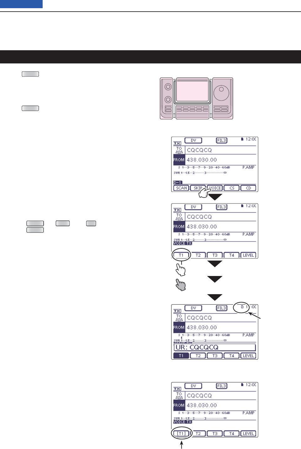
15 VOICE TX FUNCTION
15-6
Previous view
Push qMENU (C) one or more times to select the “M-
2” (Menu 2) screen.
• In the DR mode, select the “D1” screen.
Touch [VOICE]( wD) to select the Voice TX mode.
• “VOICE TX” screen is displayed.
Push eMENU (C) to display the “VOICE” screen.
r<<Single TX>>
Touch the desired memory, [T1] through [T4] to
transmit the recorded voice audio once.
<<Repeat TX>>
Touch the desired memory, [T1] through [T4] for 1
second to repeatedly transmit the recorded voice
audio for up to 10 minutes at the interval specified in
“Repeat Time.”
• Even if 10 minutes pass while transmitting, the voice au-
dio is completely transmitted.
• During the Voice TX waiting, the selected memory
blinks.
• One of the following steps will cancel the transmission.
- Touch the memory again.
- Turn OFF the power, then turn it ON again.
- Touch another memory (except for [LEVEL]).
- Push
MENU
(C),
XFC
(R) or
SET
(C).
- Push
QUICK
(C).
The repeat transmission is cancelled. But while trans-
mitting, the voice audio is completely transmitted.
• Once the Repeat TX is made, the transceiver pauses
until the end of the “Repeat Time,” then transmits again.
After the second transmission, the Repeat TX continues
pausing, if receiving a signal.
But if the squelch is manually opened, the voice audio is
repeatedly transmitted, according to the repeat time set-
ting.
• Voice TX Waiting screen for <<Repeat TX>>
Transmitting the recorded voice audio
Blinks while
transmitting
Touch
[VOICE]
Touch the
desired
memory,
Single TX
Repeat TX
Blinks
The L, R, C or D in the
instructions indicate the
part of the controller.
L: Left side
R: Right side
C: Center bottom
D: Display (Touch panel)
Left Right
Center
Display
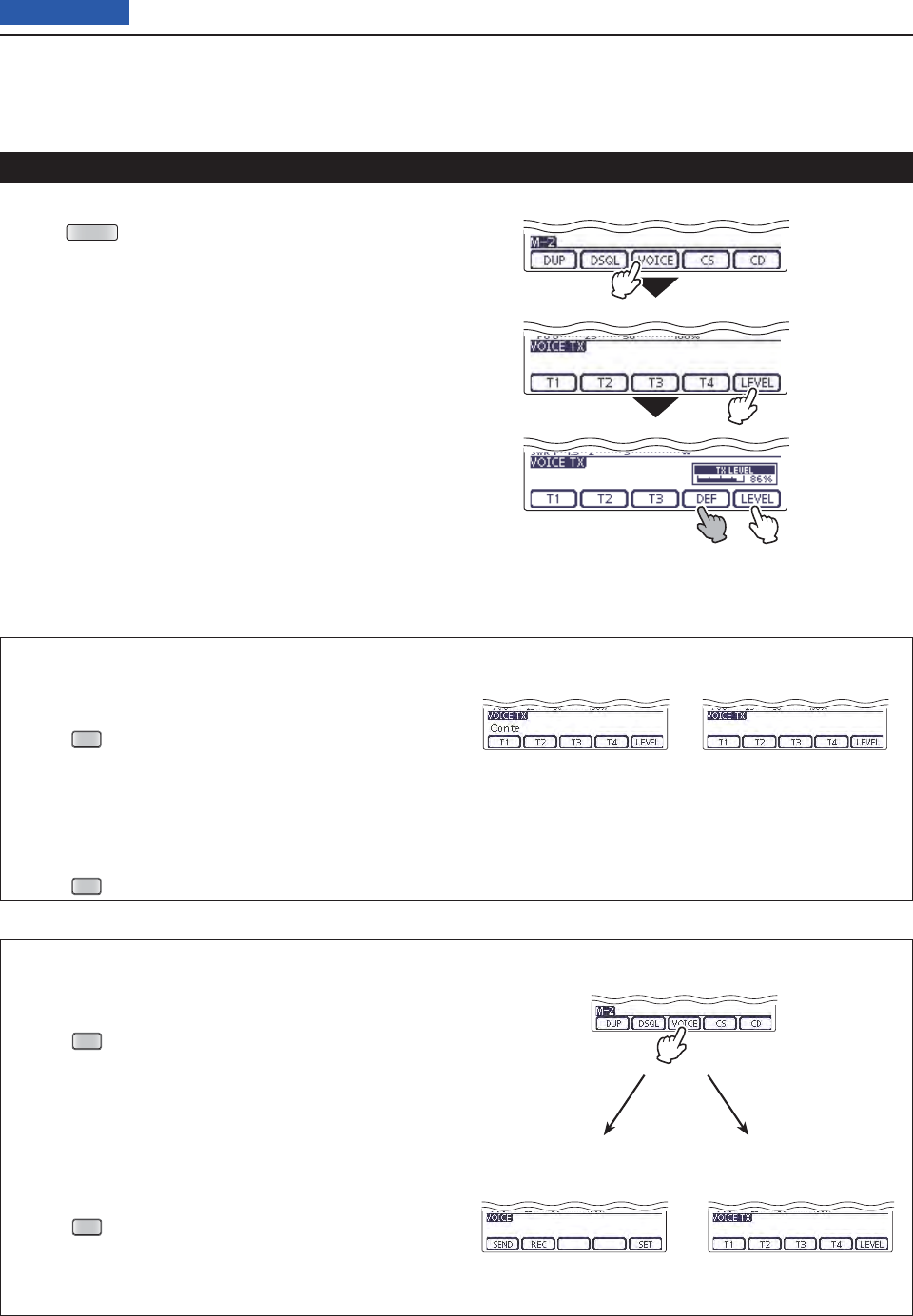
15 VOICE TX FUNCTION
15-7
Previous view
Adjusting the TX volume level D
Push qMENU (C) one or more times to select the “M-
2” (Menu 2) screen.
• In the DR mode, select the “D1” screen.
Touch [VOICE]( wD) to select the Voice TX mode.
• “VOICE TX” screen is displayed.
Touch [LEVEL]( eD) to display the “TX LEVEL”
screen.
Rotate the Dial to adjust the transmit voice level. r
• Too high of a voice level may cause interference.
• Touch [DEF](D) for 1 second to reset to the default set-
ting (50 %), if desired.
Touch [LEVEL]( tD) to save, and exit the “TX LEVEL”
screen.
Transmitting the recorded voice audio (Continued)
Touch
[VOICE]
Touch
[LEVEL]
Rotate the Dial
to adjust
Exits the “TX LEVEL”
screen.
Reset to the
default setting
Hiding the Voice TX memory name
The voice TX memory name can be hidden on the
“VOICE TX” screen.
Push q
SET
(C) to enter the Set mode.
Touch the “VOICE TX Name Display” item of the w
“Display” Set mode.
( Display > VOICE TX Name Display)
• If the specifi ed item is not displayed, touch [∫] or [√](D)
one or more times to select the page.
Touch “OFF.” e
Push r
SET
(C) to exit the Menu screen.
The voice TX memory
name is displayed.
The voice TX memory
name is not displayed.
When “ON” is selected. When “OFF” is selected.
Setting the VOICE fi rst menu screen
Select the first appearance screen after touching
[VOICE](D).
Push q
SET
(C) to enter the Set mode.
Touch the “VOICE 1st menu” item of the “Function” w
Set mode.
( Function > VOICE 1st menu)
• If the specifi ed item is not displayed, touch [∫] or [√](D)
one or more times to select the page.
Touch the desired option. e
• VOICE-Root: Displays the “VOICE” screen fi rst.
• VOICE-TX: Displays the “VOICE TX” screen fi rst.
Push r
SET
(C) to exit the Menu screen.
“M-2” (Menu 2) screen
Displays the “VOICE”
screen fi rst.
Displays the “VOICE TX”
screen fi rst.
After touching [VOICE].
When “VOICE-Root” is
selected.
When “VOICE-TX” is
selected.
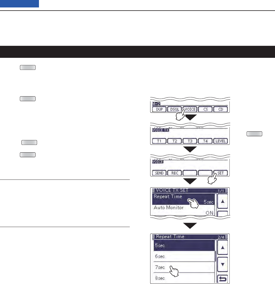
15 VOICE TX FUNCTION
15-8
Previous view
Repeat Time (Default: 5sec)
Set the repeat interval to between 1 and 15 seconds (in
1 second steps) for the voice repeat transmission.
The transceiver repeatedly transmits the recorded
voice audio at this interval.
Auto Monitor (Default: ON)
Turn the TX Monitor function ON or OFF.
• OFF: The TX voice audio is not heard from the speak-
er.
• ON: The TX voice audio is heard from the speaker.
Touch
[VOICE]
Touch [SET]
Touch a de-
sired item.
( Example: Re-
peat Time)
Touch a de-
sired option.
( Example:
7sec)
Push MENU
Voice TX Set mode
Push qMENU (C) one or more times to select the “M-
2” (Menu 2) screen.
• In the DR mode, select the “D1” screen.
Touch [VOICE]( wD) to select the Voice TX mode.
• “VOICE TX” screen is displayed.
Push eMENU (C) to display the “VOICE” screen.
Touch [SET]( rD) to display the “VOICE TX SET”
screen.
Touch a desired item. t
Touch a desired option. y
• See the descriptions below for details of items and op-
tions.
• Push QUICK (C), and then touch “Default” to reset to the
default setting, if desired.
Push uMENU (C) to return to the “VOICE” screen.

Front panel ......................................................................................... 00
Front panel ......................................................................................... 00
Front panel ......................................................................................... 00
Front panel ......................................................................................... 00
16-1
Section 16 ANTENNA TUNER OPERATION
Previous view
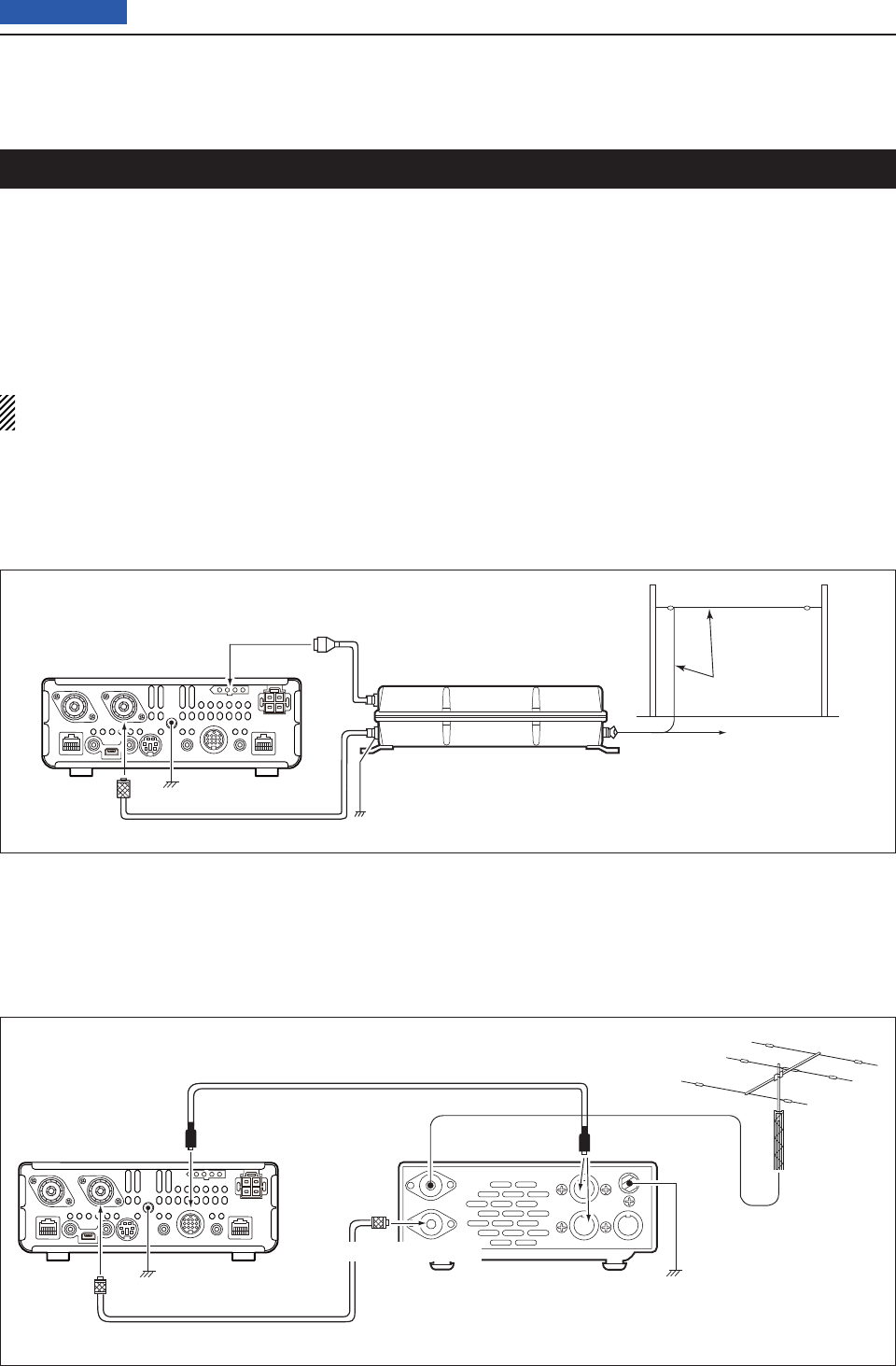
16 ANTENNA TUNER OPERATION
16-2
Previous view
Connecting the antenna tuner
To Long wire
To optional AH-2b
Ground
AH-4
To [ANT]
IC-7200
To [TUNER]
Ground*
ANT
Antenna
element
To [TRANSCEIVER]
To [ANT]
To [ACC]
AT-180
To [ANT] To [ACC]*
Ground
HF/6 m antenna
Coaxial cable supplied
with the AT-180
ACC cable supplied with the AT-180
Coaxial cable
Ground
IC-7100 *Either of the two
external connectors
* Use as thick and short a wire as possible
between the AH-4 and ground.
Connecting an AH-4 D
The optional AH-4 matches the IC-7100 to a long
wire antenna more than 7 m/23 ft long (3.5 MHz and
above).
• See page ??-?? for operation.
• See the AH-4 instruction manual installation and an-
tenna connection details.
The AH-4 and AT-180 AUTOMATIC ANTENNA TUNER
matches the IC-7100 to the connected antenna auto-
matically.
Once the tuner matches an antenna, the variable ca-
pacitor settings are memorized as a preset point for
each frequency range (100 kHz steps). Therefore, when
you change the frequency range, the variable capaci-
tors are automatically preset to the memorized point.
NOTE: Before connecting, be sure to turn OFF the
transceiver’s power.
Connecting an AT-180 D
The optional AT-180 matches the IC-7100 to both HF
and 50 MHz antenna, and automatically tunes the an-
tenna (impedance range: 16.7 to 150 ø) during trans-
mission when the antenna SWR is less than 1.5:1.
• See page ??-?? for operation.
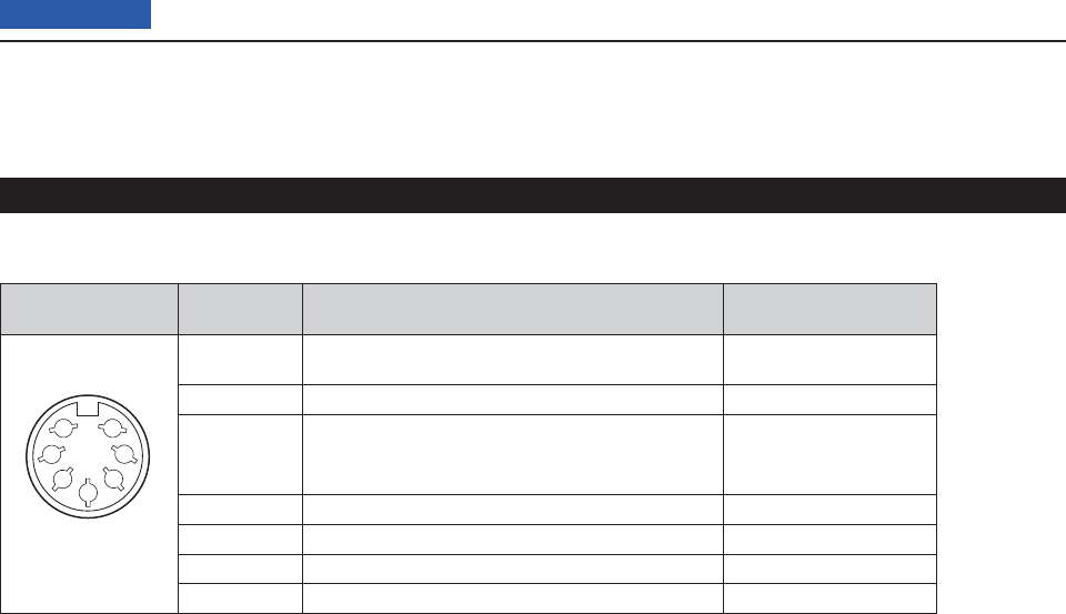
16 ANTENNA TUNER OPERATION
16-3
Previous view
Connector information for the ACC(2) socket D
PIN LAYOUT
PIN NO./
NAME DESCRIPTION SPECIFICATIONS
1
2
3
4
5
6
7
(Front panel view)
8 V qRegulated 8 V output when the Band Voltage
modifi cation is performed. (p. ??-??) Same as ACC pin q.
GND wConnects to ground. –
HSEND e
Input/output pin.
Goes to ground when transmitting
When grounded, transmits.
Same as ACC pin e.
NC rNo connection. –
ALC tALC output voltage Same as ACC pin y.
NC yNo connection. –
13.8 V u13.8 V output when power is ON Same as ACC pin i.
Specifi cations for the AH-4 D
Frequency coverage : 7–54 MHz (with an AH-2b)
3.5–54 MHz (with more than
7 meters long wire)
Input impedance : 50 ȍ
Maximum input power : 120 W
Minimum tuning power : 10 W (5–15 W)
Tuning accuracy : Less than SWR 2:1
Power supply requirements
: 13.8 V DC/1 A (supplied from
the transceiver’s ACC socket)
Dimensions (mm/in) :
172(W) u 69.5(H) u 230(D)
6.7 (W) u 2.7(H) u 9.0(D)
Weight (Approximately) : 1.2 kg; 2.6 lb
Supplied accessories : See the AH-4 instruction
manual
Specifi cations for the AT-180 D
Frequency coverage : 1.8–54 MHz
Input impedance : 50 ȍ
Maximum input power : 120 W
Minimum tuning power : 8 W
Matching impedance range
: 16.7–150 ȍ (HF band)
20–125 ȍ (50 MHz band)
Tuning accuracy : Less than SWR 1.5:1
Insertion loss : Less than 1.0 dB
(after tuning)
Power supply requirements
: 13.8 V DC/1 A (supplied from
the transceiver’s ACC socket)
Dimensions (mm/in) :
167(W) u 58.6(H) u 225(D)
6.6(W) u 2.3(H) u 8.9(D)
Weight (Approximately) : 2.3 kg; 5.1 lb
Supplied accessories : ACC cable (DIN 13 pins)
Coaxial cable (1 m),
Connecting the antenna tuner (Continued)
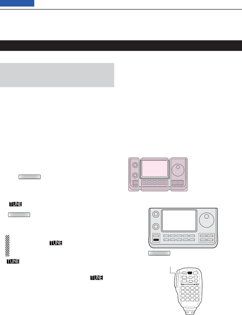
16 ANTENNA TUNER OPERATION
16-4
Previous view
Operating the AH-4
Before operating D
R DANGER HIGH VOLTAGE!
NEVER touch the antenna element while tuning or
transmitting.
Always place it in a secure place.
NEVER operate the AH-4 without an antenna connect-
ed. The tuner and transceiver will be damaged.
NEVER operate the AH-4 when it is ungrounded.
Transmitting before tuning may damage the transceiver.
Note that the AH-4 cannot tune when using a 1⁄2O long
wire or on a multiple of that frequency.
Operating D
Tuning is required for each frequency. Be sure to retune
the antenna before transmitting when you change the
frequency—even slightly.
Push q
TUNER/CALL
(L) or [TUNER/CALL] on the re-
mote control microphone to turn ON the AH-4.
The CW mode and 10 W output power are automati-
cally selected, and the tuning starts.
• The TX indicator lights red.
• “ ” blinks while tuning.
• After changing the frequency, you should hold down
TUNER/CALL
(L) or [TUNER/CALL] on the remote control
microphone for second to manually start tuning. In this
case, the CW mode and 10 W output power are auto-
matically selected, and the TX indicator lights red.
NOTE: DO NOT change the frequency and oper-
ating mode while “ ” is blinking. It may takes
approximately 2 to 3 seconds (maximum of 15
seconds) to complete tuning.
w“ ” is still ON after the tuning is completed, and
the previously selected operating mode and the out-
put power are automatically selected.
• When the connected wire cannot be tuned, “ ” goes
out, the AH-4 is bypassed and the antenna wire is di-
rectly connected.
PTT tune function D
The AH-4 always tunes when [PTT] is pushed after the
frequency is changed on an HF band (more than 1%).
Turn ON this function in the Set mode.
(Function > Tuner > PTT Start)
The L, R, C or D in the
instructions indicate the
part of the controller.
L: Left side
R: Right side
C: Center bottom
D: Display (Touch panel)
Left Right
Center
Display
TUNER/CALL
[TUNER/CALL]

16 ANTENNA TUNER OPERATION
16-5
Previous view
Operating the AT-180
Before operating D
CAUTION:
• NEVER transmit with the tuner ON if no antenna is
connected. This will damage both the transceiver
and antenna tuner.
• NEVER transmit with the tuner ON if no antenna is
connected. This will damage both the transceiver
and antenna tuner.
NEVER operate the AH-4 without an antenna connect-
ed. The tuner and transceiver will be damaged.
NEVER operate the AH-4 when it is ungrounded.
Transmitting before tuning may damage the transceiver.
Note that the AH-4 cannot tune when using a 1⁄2O long
wire or on a multiple of that frequency.
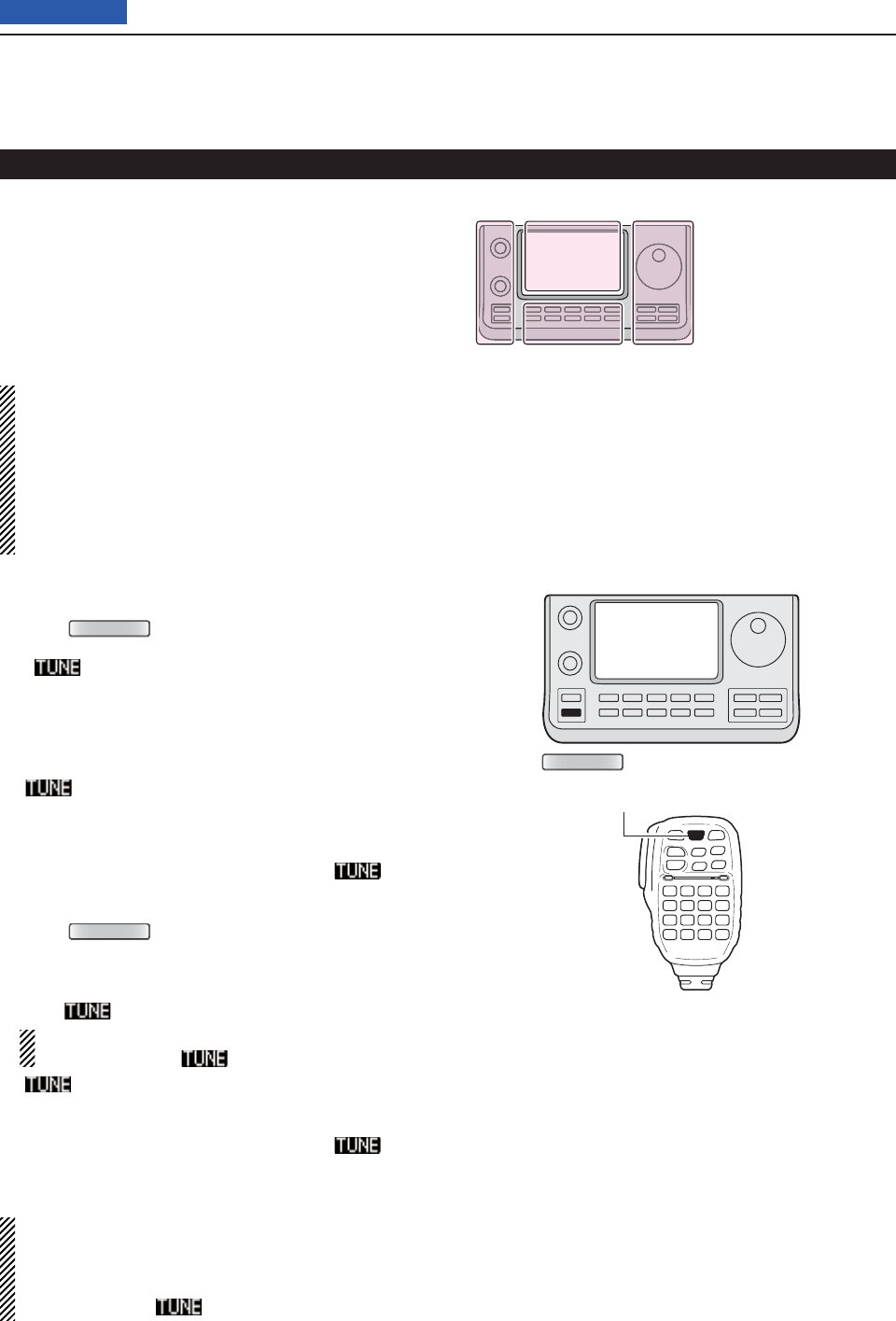
16 ANTENNA TUNER OPERATION
16-6
Previous view
Operating D
The AT-180 AUTOMATIC ANTENNA TUNER automatically
matches to your antenna. Once the tuner matches the
antenna, the variable capacitor settings are memorized
as a preset point for each frequency range (100 kHz
steps). Therefore, when you change the frequency
range, the variable capacitors are automatically preset
to the memorized point.
NOTE:
• The AT-180 can match both the HF and 50 MHz
bands. However, operation is different for the
bands.
• When connecting the AT-180, the transceiver’s out-
put power should be more than 8 W. Otherwise, the
AT-180 may not tune correctly. The AT-180’s mini-
mum operating input power is 8 W.
Check the transceiver’s output power is set to 8 W/ q
Push w
TUNER/CALL
(L) or [TUNER/CALL] on the re-
mote control microphone to turn ON the AT-180.
• “ ” appears.
For the HF band:
The antenna is automatically tuned during transmit if
the antenna SWR is higher than 1.5:1.
For the 50 MHz band:
“” blinks if the antenna SWR is higher than
1.5:1, regardless of the internal switch position de-
scribed on the page ??-??. In this case, do the step
e to manually tune the antenna.
• If you continue to transmit without retuning, “ ” goes
out after approximately 10 seconds, the AH-4 is bypassed
and the antenna wire is directly connected.
Push e
TUNER/CALL
(L) or [TUNER/CALL] on the re-
mote control microphone for 1 second to start man-
ual tuning.
• When the CW mode is selected, a side tone is emitted,
and “ ” blinks.
NOTE: DO NOT change the frequency and oper-
ating mode while “ ” is blinking.
r“ ” is still ON after the tuning is completed, and
the previously selected operating mode is automati-
cally selected.
• When the connected wire cannot be tuned, “ ” goes
out, the AH-4 is bypassed and the antenna wire is di-
rectly connected.
Once the tuner matches the antenna, the variable
capacitors are automatically preset to the memo-
rized point when you change the frequency range in
100 kHz steps.
• While presetting, “ ” blinks.
Operating the AT-180 (Continued)
TUNER/CALL
[TUNER/CALL]
The L, R, C or D in the
instructions indicate the
part of the controller.
L: Left side
R: Right side
C: Center bottom
D: Display (Touch panel)
Left Right
Center
Display
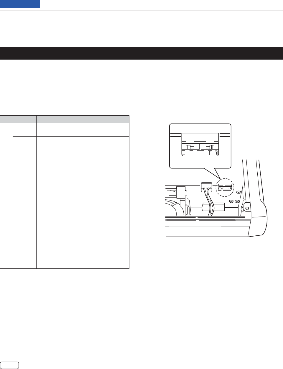
16 ANTENNA TUNER OPERATION
16-7
Previous view
Setting the AT-180 internal switches
The optional AT-180 has 3 operating confi gurations for
HF band operation. Select a suitable confi gurations for
your antenna system.
q Remove the top cover of the AT-180.
w Set the tuner switches to the desired positions ac-
cording to the table below.
Automatic tuner start D(HF bands only)
If you want to turn OFF the tuner when the VSWR is
1.5:1 or less, use “automatic tuner on” and turn OFF
the tuner. See page 10-11 for automatic tuner function.
PTT tune function D
The AT-180 tunes when [PTT] is pushed after the
frequency is changed (more than 1%) if the AT-180
is turned ON. This function removes the “hold down
TUNER ” operation and activates with the fi rst transmis-
sion on the new frequency. (p. 10-11)
Turn this function ON in the Set mode.
SW Position Operation
S1
A
(default)
The tuner operating mode is set by S2
described below.
BTHROUGH INHIBIT
The tuner tunes the antenna even when
the antenna has poor SWR (up to VSWR
3:1 after tuning). In this case, manual tun-
ing is necessary each time you change
the frequency although the tuner auto-
matically starts tuning when the VSWR
is higher than 3:1. This setting is called
“through inhibit,” however, the tuner is set
to “through” if the VSWR is higher than
3:1 after tuning.
S2
CTUNER SENSITIVE SETTING
The tuner tunes each time you transmit
(except SSB mode). Therefore, the low-
est SWR is obtained at any given time.
For SSB mode, the same SETTING as
the “D” position.
D
(default)
NORMAL
The tuner tunes when the SWR is higher
than 1.5:1. Therefore, the tuner activates
only when tuning is necessary.
• AT-180 inside top cover
S2 S1
DC BA

17-1
Section 17 SET MODE
Previous view
Set mode description ............................................................17-2
The Set mode settings
D ..........................................................17-2
Set mode items and Default settings ...................................17-3
Voice Memo Set mode ...........................................................17-11
DV Set mode ..........................................................................17-13
SPEECH Set mode .................................................................17-15
QSO/RX Log Set mode ..........................................................17-16
Function Set mode ................................................................17-18
Tone Control Set mode .........................................................17-23
Connectors Set mode ...........................................................17-24
Display Set mode ...................................................................17-27
Time Set Set mode ................................................................17-30
Others Set mode ....................................................................17-31
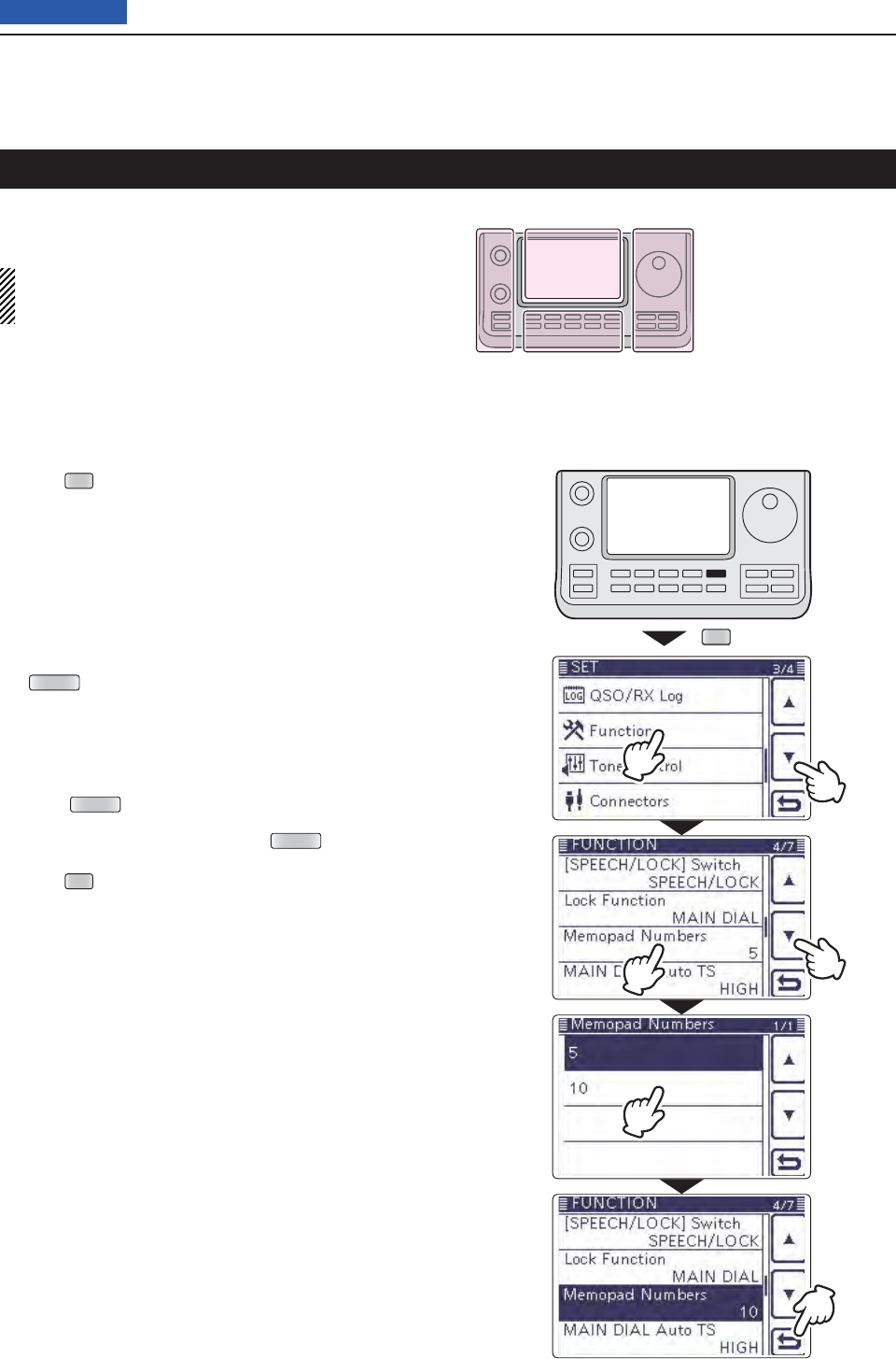
17 SET MODE
17-2
Previous view
The Set mode is used to program infrequently changed
values or function settings.
NOTE: The Set mode is constructed in a tree struc-
ture. You may go to the next tree level, or go back a
level, depending on the selected item.
SET
w
e
r
u
t
y
The Set mode settings D
Push q
SET
(C) to enter the Set mode.
If the specifi ed item is not displayed, touch [ w∫] or [√]
(D) one or more times to select the page.
• If [∫](D) or [√](D) is continuously held down, the pages
are quickly scrolled.
• Rotating the Dial also selects the pages.
Touch the desired item to go to the next level. e
Repeat steps rw and e to show the desired item’s
setting screen.
• To go back the previous tree level, touch [](D), or
MENU (C).
Touch a desired option shown on the display, or [+]/ t
[–](D) to adjust a level.
• When you touch an option, it is automatically saved and
the screen returns to the previous display.
• Rotating the Dial also adjusts the level.
• Push QUICK (C), and then touch “Default” to reset to the
default setting, if desired.
• To set other item, touch [](D), or MENU (C) to go back
a tree level.
Push y
SET
(C) to exit the Set mode.
Set mode description
The L, R, C or D in the
instructions indicate the
part of the controller.
L: Left side
R: Right side
C: Center bottom
D: Display (Touch panel)
Left Right
Center
Display

17 SET MODE
17-3
Previous view
NOTE: The default settings shown below in bold are for the USA version.
The default settings may differ, depending on your transceiver version.
Call sign (Section 9) ➥
RX Record (Section 9) ➥
MY Station (Section 7) ➥
SD Card (Section 13) ➥
GPS (Section 10) ➥
Voice Memo In this item, set the TX/RX voice recording options.
QSO Recorder
<<REC Start>>* Starts recording the received audio.
Play Files*
Selects to playback or delete the recorded audio.
Recorder Set
REC Mode TX&RX or RX Only Selects to record the TX audio or not.
RX REC Condition Always or Squelch Auto Selects whether or not the squelch status affects
the RX voice audio recording.
File Split OFF or ON Selects whether or not to automatically create
a new fi le after each transmission, reception, or
each time the squelch opens or closes.
PTT Auto REC OFF or ON Turns the PTT Automatic Recording function ON
or OFF.
Player Set
Skip Time 3sec, 5sec, 10sec or 30sec Sets the Skip time to rewind or forward the re-
corded audio when you push the fast-rewind or
fast-forward key during playback.
DV Auto Reply* Records a voice audio to use for the Auto Reply
function in the DV mode.
* Be sure to insert the SD card into the transceiver before selecting these items.
DV Set In this item, set infrequently changed values or functions in the DV mode.
Standby Beep OFF, ON or ON (to me: High Tone) Selects whether or not to sound a beep after a
received signal disappears.
Auto Reply OFF, ON or Voice Selects whether or not to automatically reply to a
call addressed to your own call sign.
DV Data TX PTT or Auto Selects to manually or automatically transmit low
speed data.
Digital Monitor Auto, Digital or Analog Selects the DV mode RX monitoring when [XFC]
is held down.
Digital Repeater Set OFF or ON Turns the digital repeater setting function ON or
OFF. This function is usable in any DV mode ex-
cept the DR mode.
RX Call Sign Write OFF or Auto Turns the RX call sign automatic write function
ON or OFF. This function is usable in any DV
mode except the DR mode.
RX Repeater Write OFF or Auto Turns the repeater call sign automatic write func-
tion ON or OFF. This function is usable in any DV
mode except the DR mode.
DV Auto Detect OFF or ON Turns the DV mode automatic detect function ON
or OFF.
RX Record (RPT) ALL or Latest Only Selects whether to record all calls or only the lat-
est call, when the received signal includes a sta-
tus message (“UR?” or “RPT?”) that is sent back
from the access repeater.
BK OFF or ON Turns the BK (Break-in) function ON or OFF.
The BK function allows you to break into a con-
versation between two stations with call sign
squelch enabled.
EMR OFF or ON Turns the EMR (Enhanced Monitor Request)
communication mode ON or OFF.
After turning OFF the transceiver, the EMR mode
will be cancelled.
EMR AF Level 0%~50%~100% Sets the audio output level when an EMR mode
signal is received.
Set mode items and Default settings
17 SET MODE
17-4
Previous view
SPEECH In this item, set the Speech options.
RX Call Sign SPEECH OFF, ON (Kerchunk) or ON (All) Selects the RX call sign speech function option
while ON, or turn it OFF.
RX>CS SPEECH OFF or ON Turns the RX>CS Speech function ON or OFF.
S-Level SPEECH OFF or ON Turns the Signal Strength Level Speech function
ON or OFF.
MODE SPEECH OFF or ON Turns the Operating Mode Speech function ON
or OFF.
SPEECH Language English or Japanese Selects either English or Japanese as the de-
sired speech language.
Alphabet Normal or Phonetic Code Selects the alphabet character announcement
type.
SPEECH Speed Slow or Fast Selects Slow or Fast speech speed.
SPEECH Level 0%~50%~100% Sets the volume level for the voice synthesizer.
QSO/RX Log In this item, set the QSO/RX History Log options.
QSO Log*1OFF or ON Selects whether or not to make a communication
log on the SD card.
RX History Log*1OFF or ON Selects whether or not to make a DV mode’s re-
ceive history log on the SD card.
CSV Format
Separator/Decimal Sep [,] Dec [.]*2, Sep [;] Dec [.] or Sep
[;] Dec [,]
Selects the separator and the decimal character
for the CSV format.
Date yyyy/mm/dd, mm/dd/yyyy*2 or dd/mm/
yyyy
Selects the date format.
*1 Be sure to insert the SD card into the transceiver before selecting these items.
*2 The default value may differ, depending on the transceiver version.
Set mode items and Default settings (Continued)
NOTE: The default settings shown below in bold are for the USA version.
The default settings may differ, depending on your transceiver version.

17 SET MODE
17-5
Previous view
Function In this item, set the function options.
Monitor OFF or ON Selects whether or not to monitor your transmit
signal in any mode other than CW.
Monitor Level 0%~50%~100% Sets the monitor level.
Beep Level 0%~50%~100% Sets the beep output level.
Beep Level Limit OFF or ON Selects whether or not to limit the volume to the
specifi ed level, and further rotation of the [AF]
control will not increase the level.
Beep (Confi rmation) OFF or ON Turns the confi rmation beep tones ON or OFF.
Band Edge Beep OFF, ON (Default), ON (User) or ON
(User) & TX Limit
Selects whether or not to sound a beep when you
tune outside of, or back into the amateur band's
frequency range.
User Band Edge 1: 1.800.000–1.999.999
2: 3.500.000–3.999.999
3: 7.000.000–7.300.000
4: 10.100.000–10.150.000
5: 14.000.000–14.350.000
6: 18.068.000–18.168.000
7: 21.000.000–21.450.000
8: 24.890.000–24.990.000
9: 28.000.000–29.700.000
10: 50.000.000–54.000.000
11:
144.000.000
–
146.000.000
12:
430.000.000
–
440.000.000
13~30: (blank)
Selects the user band frequency range to sound
a beep when the Band Edge Beep function is
set to “ON (User)” or “ON (User) & TX Limit,” and
you tune outside of, or back into a programmed
range.
RF/SQL Control Auto, SQL or RF+SQL Select the function of the [RF/SQL] control.
TX Delay
HF OFF, 10ms, 15ms, 20ms, 25ms or
30ms
Sets the transmission’s timing of the IC-7100 to
prevent any external equipment that is connected
from damage by the refl ected wave.
50M OFF, 10ms, 15ms, 20ms, 25ms or
30ms
Sets the transmission’s timing of the IC-7100 to
prevent any external equipment that is connected
from damage by the refl ected wave.
144M OFF, 10ms, 15ms, 20ms, 25ms or
30ms
Sets the transmission’s timing of the IC-7100 to
prevent any external equipment that is connected
from damage by the refl ected wave.
430M OFF, 10ms, 15ms, 20ms, 25ms or
30ms
Sets the transmission’s timing of the IC-7100 to
prevent any external equipment that is connected
from damage by the refl ected wave.
Time-Out Timer OFF, 3min, 5min, 10min, 20min or
30min
Selects the Time-Out Timer time options to pre-
vent an accidental prolonged transmission.
PTT Lock OFF or ON Selects whether or not to inhibit transmission.
SPLIT/DUP
Quick SPLIT OFF or ON Turns the Quick SPLIT function ON or OFF.
SPLIT Offset –9.999 MHz~0.000 MHz~+9.999 MHz Sets the frequency offset for the Split function.
SPLIT LOCK OFF or ON Turns the SPLIT LOCK function ON or OFF.
DUP Offset
0.0000 MHz~9.9999 MHz
( The default value may differ, depend-
ing on the frequency band and the
transceiver version.)
Sets the frequency offset for repeater operation.
One Touch Repeater DUP– or DUP+ Selects the duplex direction for the One Touch
Repeater function.
Auto Repeater OFF, ON (DUP) or ON (DUP,TONE) Turns the Auto Repeater function ON or OFF.
Set mode items and Default settings (Continued)
NOTE: The default settings shown below in bold are for the USA version.
The default settings may differ, depending on your transceiver version.

17 SET MODE
17-6
Previous view
Tuner
Auto Start OFF or ON Turns the automatic antenna tuner function ON
or OFF.
PTT Start OFF or ON Turns the PTT Tuner Start function ON or OFF.
[TUNER] Switch Manual or Auto Selects whether or not to store the AT-180’s sta-
tus by each band.
[SPEECH/LOCK] Switch SPEECH/LOCK, LOCK/SPEECH Selects the function for
SPEECH
when pushed
or held down.
Lock Function MAIN DIAL or PANEL Selects the dial lock function to prevent frequen-
cy changes by accidental movement of the tun-
ing dial.
Memopad Numbers 5 or 10 Sets the number of usable memopad channels.
MAIN DIAL Auto TS OFF, LOW or HIGH Selects an option for the automatic tuning step
function. When rapidly rotating the main dial, the
tuning step automatically changes according to
the setting.
MIC Up/Down Speed Slow or Fast Selects the steps per second when changing an
operating frequency by holding down the micro-
phone’s [∫]/[√] key.
[NOTCH] Switch (SSB) Auto, Manual or Auto/Manual Selects the notch function for the SSB mode.
[NOTCH] Switch (AM) Auto, Manual or Auto/Manual Selects the notch function for the AM mode.
SSB/CW Sync Tuning OFF or ON Turns the Synchronous Tuning function ON or
OFF to shift the operating frequency by the offset
amount to keep receiving a signal when the oper-
ating mode is changed between SSB and CW.
CW Normal Side LSB or USB Sets the carrier point for CW normal mode op-
eration to the LSB side or the USB side.
VOICE 1st Menu VOICE-Root or VOICE-TX Select whether or not to directly select the voice
send menu, skipping the voice menu.
KEYER 1st Menu KEYER-Root or KEYER-SEND Select whether or not to directly select the keyer
send menu, skipping the memory keyer menu.
Speaker Out OFF or ON Selects to mute the speaker output.
MIC AF Out OFF or ON Selects to output the received audio from the
[MIC] connector.
RC MIC
[F-1] ---, P.AMP/ATT, AGC, NB, NR, NOTCH,
RIT, AUTOTUNE/RX>CS, TS, MPAD,
M-CLR, BANK, SPLIT, A/B, DUP,
TONE/DSQL, COMP, TBW, METER,
DR, FROM/TO(DR), SCAN, Voice TX
(T1)
The functions listed to the left can be set to [F-1]
of the optional HM-151 REMOTE CONTROL MIC.
[F-2] ---, P.AMP/ATT, AGC, NB, NR, NOTCH,
RIT, AUTOTUNE/RX>CS, TS, MPAD,
M-CLR, BANK, SPLIT, A/B, DUP,
TONE/DSQL, COMP, TBW, METER,
DR, FROM/TO(DR), SCAN, Voice TX
(T1)
The functions listed to the left can be set to [F-2]
of the optional HM-151 REMOTE CONTROL MIC.
Mode Select SSB, CW, RTTY, AM, FM,
WFM, DV
(All boxes are checked.)
Disables the mode selection of the optional HM-
151 REMOTE CONTROL MIC, to simplify operation.
Power OFF (With No Controller) OFF or ON Selects whether or not to automatically turn OFF
the transceiver when the controller is disconnect-
ed from the transceiver.
REF Adjust 0 %~100 % Sets a number to adjust for a zero beat with a
standard signal such as WWV or WWVH, for fre-
quency calibration.
Set mode items and Default settings (Continued)
NOTE: The default settings shown below in bold are for the USA version.
The default settings may differ, depending on your transceiver version.

17 SET MODE
17-7
Previous view
Tone Control In this item, set the RX/TX tone control options.
RX
SSB
RX HPF/LPF ---- – ----, 100~2000 – 500~2400 Sets the high-pass fi lter or low-pass fi lter of the
receive audio.
RX Bass –5~0~+5 Sets the bass level of the receive audio.
RX Treble –5~0~+5 Sets the treble level of the receive audio.
AM
RX HPF/LPF ---- – ----, 100~2000 – 500~2400 Sets the high-pass fi lter or low-pass fi lter of the
receive audio.
RX Bass –5~0~+5 Sets the bass level of the receive audio.
RX Treble –5~0~+5 Sets the treble level of the receive audio.
FM
RX HPF/LPF ---- – ----, 100~2000 – 500~2400 Sets the high-pass fi lter or low-pass fi lter of the
receive audio.
RX Bass –5~0~+5 Sets the bass level of the receive audio.
RX Treble –5~0~+5 Sets the treble level of the receive audio.
DV
RX HPF/LPF ---- – ----, 100~2000 – 500~2400 Sets the high-pass fi lter or low-pass fi lter of the
receive audio.
RX Bass –5~0~+5 Sets the bass level of the receive audio.
RX Treble –5~0~+5 Sets the treble level of the receive audio.
WFM
RX Bass –5~0~+5 Sets the bass level of the receive audio.
RX Treble –5~0~+5 Sets the treble level of the receive audio.
CW
RX HPF/LPF ---- – ----, 100~2000 – 500~2400 Sets the high-pass fi lter or low-pass fi lter of the
receive audio.
RTTY
RX HPF/LPF ---- – ----, 100~2000 – 500~2400 Sets the high-pass fi lter or low-pass fi lter of the
receive audio.
TX
SSB
TX Bass –5~0~+5 Sets the bass level of the transmit audio.
TX Treble –5~0~+5 Sets the treble level of the transmit audio.
TBW (WIDE) 100, 200, 300, 500 – 2500, 2700,
2800, 2900
Sets the lower and higher cut-off frequencies to
change the transmission passband width for the
wide setting.
TBW (MID) 100, 200, 300, 500 – 2500, 2700,
2800, 2900
Sets the lower and higher cut-off frequencies to
change the transmission passband width for the
mid setting.
TBW (NAR) 100, 200, 300, 500 – 2500, 2700,
2800, 2900
Sets the lower and higher cut-off frequencies to
change the transmission passband width for the
narrow setting.
AM
TX Bass –5~0~+5 Sets the bass level of the transmit audio.
TX Treble –5~0~+5 Sets the treble level of the transmit audio.
FM
TX Bass –5~0~+5 Sets the bass level of the transmit audio.
TX Treble –5~0~+5 Sets the treble level of the transmit audio.
DV
TX Bass –5~0~+5 Sets the bass level of the transmit audio.
TX Treble –5~0~+5 Sets the treble level of the transmit audio.
Set mode items and Default settings (Continued)
NOTE: The default settings shown below in bold are for the USA version.
The default settings may differ, depending on your transceiver version.

17 SET MODE
17-8
Previous view
Connectors In this item, set the external connector’s options.
USB Audio SQL OFF (OPEN) or ON Selects whether or not to output the audio from
the [USB] connector, according to the squelch
state (open or closed).
ACC/USB Output Select AF or IF Sets the [USB] connector and the [ACC] socket
usage to received audio output or the IF output
for DRM (Digital Radio Mondiale).
ACC/USB AF Level 0 %~50 %~100 % Sets the audio output level at the [ACC] socket
and the [USB] connector.
ACC/USB IF Level 0 %~50 %~100 % Sets the IF output level at the [ACC] socket and
the [USB] connector.
ACC MOD Level 0 %~50 %~100 % Sets the input modulation level at the [ACC]
socket.
DATA MOD Level 0 %~50 %~100 % Sets the input modulation level at the [DATA]
jack.
USB MOD Level 0 %~50 %~100 % Sets the input modulation level at the [USB] con-
nector.
DATA OFF MOD MIC, ACC, MIC,ACC or USB Selects the connector(s) for the desired modula-
tion to input when the data mode is not used.
DATA MOD MIC, ACC, MIC,ACC or USB Selects the connector(s) for the desired modula-
tion to input when the data mode is used.
External Keypad
VOICE OFF or ON Selects whether or not to transmit voice memory
contents using the external keypad.
KEYER OFF or ON Selects whether or not to transmit keyer memory
contents using the external keypad.
RTTY OFF or ON Selects whether or not to transmit RTTY memory
contents using the external keypad.
CI-V
CI-V Baud Rate 300, 1200, 4800, 9600, 19200 or Auto Sets the CI-V code transfer speed.
CI-V Address 01h~88h~DFh Sets the transceiver's unique CI-V hexadecimal
address code.
CI-V Transceive OFF or ON Turns the CI-V Transceive function ON or OFF.
USB2/DATA1 Function
USB2 Function OFF, RTTY Decode or DV Data Selects the use of the COM port (USB2).
DATA1 Function OFF, RTTY Decode, DV Data or GPS Select the use of the [DATA1] jack.
GPS Out OFF or DATA1 USB2 Selects whether or not to output the data to the
COM port (USB2) when data is input from a GPS
receiver through the [DATA1] jack.
DV Data/GPS Out Baud 4800 or 9600 Sets the DV or GPS data transfer speed
RTTY Decode Baud 300, 1200, 4800, 9600 or 19200 Sets the RTTY decode monitor speed.
VSEND Select OFF, UHF or VHF/UHF Selects the band to use for the [ACC] socket’s pin
7 (VSEND usage).
9600bps Mode OFF or ON Selects whether or not to allow data transmission
at 9600 bps.
Set mode items and Default settings (Continued)
NOTE: The default settings shown below in bold are for the USA version.
The default settings may differ, depending on your transceiver version.

17 SET MODE
17-9
Previous view
Display In this item, set the transceiver’s display options.
LCD Contrast 0%~25%~100% Sets the contrast level of the LCD.
LCD Backlight 0%~50%~100% Sets the backlight level of the LCD.
Key Backlight 0%~50%~100% Sets the backlight level of the key.
Meter Peak Hold OFF or ON Turns the Meter Peak Hold function ON or OFF.
BW Popup (PBT) OFF or ON Selects whether or not to display the PBT shifting
value while rotating the TWIN-PBT control.
BW Popup (FIL) OFF or ON Selects whether or not to display the IF fi lter width
and shifting value when the IF fi lter is switched.
RX Call Sign Display OFF, Auto or Auto (RX Hold) Selects whether or not to display the call sign of
the caller station when a call is received.
RX Message Display OFF or Auto Selects whether or not to display and scroll a re-
ceived message.
Reply Position Display OFF or ON Selects whether or not to display the caller’s po-
sition data when the data is included in the Auto
Replay signal.
TX Call Sign Display OFF, Your Call Sign or My Call Sign Selects whether or not to display My or Your call
sign while transmitting.
Scroll Speed Slow or Fast Sets the scrolling speed of the message, call
sign, or other text, that are displayed on the
transceiver’s LCD.
VOICE TX Name Display OFF or ON Selects whether or not to display the voice TX
memory name on the voice TX memory selec-
tion display.
KEYER Memory Display OFF or ON Selects whether or not to display the keyer mem-
ory contents on the keyer send selection display.
Opening Message OFF or ON Selects whether or not to display the opening
message at power ON.
Power ON Check OFF or ON Selects whether or not to display the RF Power,
RIT, Auto Power OFF condition at power ON.
Display Language English or Japanese Sets the screen display language type in the DR
mode or Menu mode.
When the System Language is “English,” this
item disappears.
System Language English or Japanese Sets the system language of the transceiver.
Time Set In this item, set the time options.
Date/Time
DATE 2000/01/01~2099/12/31 Sets the date.
TIME 0:00~23:59 Sets the time.
GPS Time Correct OFF or Auto Selects whether or not to automatically correct
the time data by a received GPS sentence.
UTC Offset –14:00~+9:00~+14:00 Sets the time difference between UTC (Universal
Time Coordinated) and the local time.
Clock Display Local or UTC Sets the clock display mode.
Auto Power OFF OFF, 30min, 60min, 90min or 120min Sets to automatically turn OFF the transceiver
power after no operation is made during this set
period.
Set mode items and Default settings (Continued)
NOTE: The default settings shown below in bold are for the USA version.
The default settings may differ, depending on your transceiver version.
17 SET MODE
17-10
Previous view
Others In this item, set other options.
Information
Version Shows the transceiver’s fi rmware version num-
ber.
Clone
Clone Mode Reads or writes the CS-7100 data to or from the
PC, and/or receives data from a Master trans-
ceiver.
Clone Master Mode Writes your IC-7100 (Master) data to another IC-
7100 (Sub).
Touch Screen Calibration Adjusts the touch screen.
Reset
Partial Reset Returns all settings to their default values, with-
out clearing the memory contents, call sign
memories or repeater lists.
All Reset Clears all programming and memories, and re-
turn all settings to their default values.
Set mode items and Default settings (Continued)
NOTE: The default settings shown below in bold are for the USA version.
The default settings may differ, depending on your transceiver version.
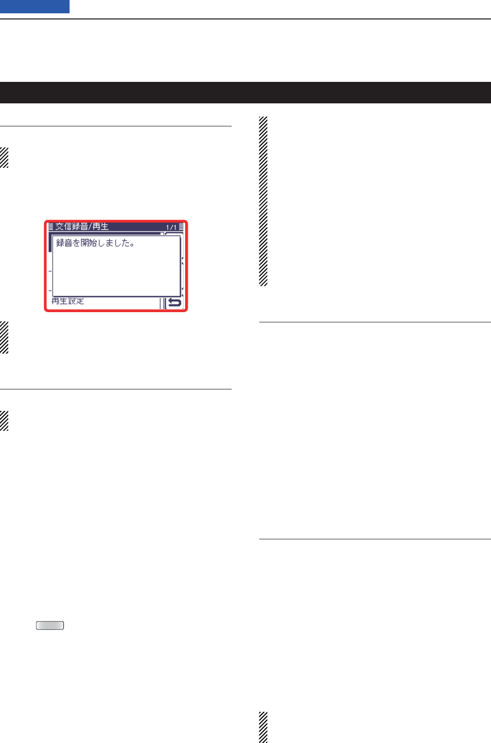
17 SET MODE
17-11
Previous view
<<REC Start>>
Voice Memo > QSO Recorder > <<REC Start>>
Insert an SD card into the transceiver before select-
ing this item.
Touch [<<REC Start>>] to start voice recording.
• “Recording started.” appears.
• [<<REC Stop>>] is displayed while recording.
Once recording has started, the recording will con-
tinue, even the transceiver is rebooted.
To stop the recording, touch [<<REC Stop>>].
Play Files
Voice Memo > QSO Recorder > Play Files (PLAY FILES)
Insert an SD card into the transceiver before select-
ing this item.
Do the following steps to play back the recorded audio
on the SD card.
Touch [Play Files], and folders on the SD card are dis-
played.
• These folders contain the stored fi les.
Playing back
Touch [ q∫] or [√], or rotate [DIAL] to select the folder
that includes the desired fi le to play back, and then
touch the folder.
Touch [ w∫] or [√], or rotate [DIAL] to select the fi le to
play back, and then touch the fi le.
• The VOICE PLAYER screen is displayed and the select-
ed fi le is played back.
• See “Operation while playing back” for forwording or re-
winding. (p. ??-??)
Push eMENU or touch [] on the display to stop the
playback.
• Returns to the fi le list screen.
NOTE:
• The folder name is automatically created, as shown
in the example below:
(Example) Recording date: 2013/3/1
Folder name: 20130301
• The fi le name is automatically created, as shown in
the example below:
(Example) Recording date: 2013/3/1 15:30:00
File name: 20130301_153000
• The voice audio is recorded onto an SD card, and
saved in the “wav” format.
The recorded voice audio can also be played back
on a PC.
The extension, “wav,” is not displayed on the trans-
ceiver’s screen.
REC Mode (Default: TX&RX)
Voice Memo > QSO Recorder > Recorder Set > REC
Mode (REC Mode)
Records both the transmitted and received audio as the
default setting.
• TX&RX: Records both the transmitted and received
audio.
• RX Only: Records only the received audio.
When transmitting while recording
When “OFF” is selected in File Split, the recording is
paused. After you stop transmitting, the recording re-
sumes.
When “ON” is selected in File Split, a new fi le is auto-
matically created, and the transmitted audio is recorded
into the new one.
RX REC Condition (Default: Squelch Auto)
Voice Memo > QSO Recorder > Recorder Set > RX
REC Condition (RX REC Condition)
Select whether or not the squelch status affects the RX
voice audio recording.
• Always: The transceiver always records the RX
audio regardless of the squelch sta-
tus.
• Squelch Auto: The transceiver records the RX audio
only when a signal is received (the
squelch is opened).
When the squelch closes while record-
ing, the recording will continue for 2
seconds, and then pause.
When “ON” is selected in File Split, and if the squelch
either opens or closes while recording, a new fi le is
automatically created.
Voice Memo Set mode
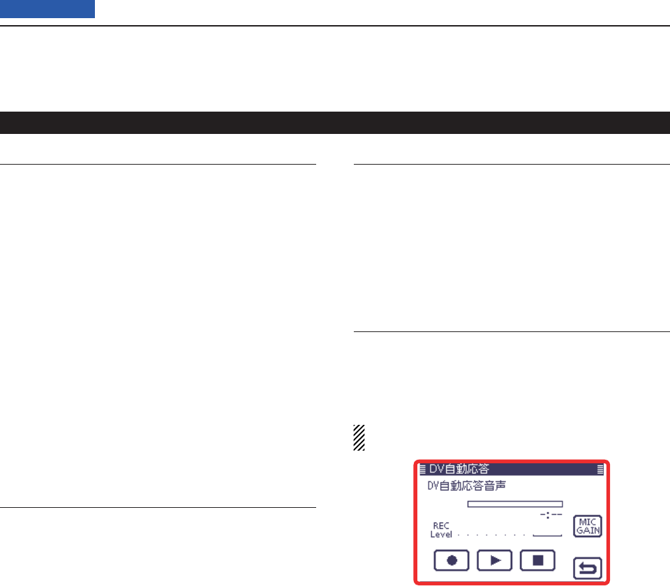
17 SET MODE
17-12
Previous view
File Split (Default: ON)
Voice Memo > QSO Recorder > Recorder Set > File
Split (File Split)
Turn the File Split function ON or OFF.
• OFF: When the recording starts, a new fi le is auto-
matically created in the folder of the SD card.
The audio is continuously recorded into the
fi le, even if transmission and reception, or the
squelch status (open and close) is switched.
If the fi le size exceeds 2 GB, a new fi le is au-
tomatically created in the same folder, and the
audio is recorded there.
• ON: When the recording starts, a new fi le is auto-
matically created in the folder of the SD card.
During recording, and if transmission and re-
ception, or squelch status (open and close) is
switched, a new fi le is automatically created in
the same folder, and the audio is saved into the
new one.
PTT Auto REC (Default: OFF)
Voice Memo > QSO Recorder > Recorder Set > PTT
Auto REC (PTT Auto REC)
Turn the PTT Automatic Recording function ON or
OFF.
Recording starts when a signal is transmitted from an
external speaker microphone, the VOX functions or a
CI-V command is sent.
• OFF: The recording does not start even if a signal is
transmitted.
• ON: The recording automatically starts when a sig-
nal is transmitted.
The recording will stop when:
• No signal is transmitted for 10 seconds after the last
transmission.
• No signal is received for 10 seconds after the last
transmission.
- 10 minutes after the last transmission while the
squelch is open (SSB/CW/RTTY/AM modes.)
- A signal is received within 10 seconds after the last
transmission, the received signal is also recorded.
A signal is received within 10 seconds after the last
reception, the received signal is also recorded.
• The frequency or operating mode is changed while
transmitting.
• The operating method (V/M, CALL, DR, M-CH, Band
Stacking Register, and so on) has been changed.
Skip Time (Default: 10sec)
Voice Memo > QSO Recorder > Player Set > Skip Time
(Skip Time)
Set the SkipTimer to 3, 5, 10 or 30 seconds to rewind
or skip forward for this set period when you push the
fast-rewind or fast-forward key.
• See “Operation while playing back” for forwording or rewind-
ing operation. (p. ??-??)
DV Auto Reply
Voice Memo > DV Auto Reply (DV AUTO REPLY)
Up to 10 seconds of audio can be recorded for the au-
tomatic reply function.
See page ??-?? for details of recording audio.
Be sure to insert an SD card into the transceiver be-
fore selecting this item.
Voice Memo Set mode (Continued)

17 SET MODE
17-13
Previous view
Standby Beep (Default: ON)
DV Set > Standby Beep (Standby Beep)
Turn the standby beep function ON or OFF.
This function sounds a beep after a received signal dis-
appears.
• OFF: Turns the function OFF.
• ON: Turns the function ON to sound a beep.
• ON (to me: High Tone):
Turns the function ON to sound a beep. If the
signal is addressed to your call sign, a high
pitch beep sounds.
NOTE:
• Even if “Beep (Confirmation)” of the Function screen
is OFF, the standby beep sounds.
• The standby beep output level can be set in “Beep
Level” of the Function screen.
Auto Reply (Default: OFF)
DV Set > Auto Reply (Auto Reply)
Set the automatic reply function to ON, OFF or Voice.
This function automatically replies to a call addressed
to your own call sign, even if you are away from the
transceiver.
When “ON” or “Voice” is selected, the automatic reply
function is automatically turned OFF when you push
[PTT].
• OFF: The automatic reply function is OFF.
• ON: Replies with your own call sign. (No audio reply
is sent)
• Voice: Replies with your call sign and any Auto Reply
message recorded on the microSD (up to 10
seconds).
If no SD card is inserted or no message is re-
corded, only your call sign is transmitted. The
transmitted audio will be heard from the speak-
er.
DV Data TX (Default: Auto)
DV Set > DV Data TX (DV Data TX)
Select whether to manually or automatically transmit
slow-speed data.
• PTT: Push [PTT] to manually transmit the input data.
• Auto: When data is input from a PC through either the
[USB2] port or [DATA1] jack*, the transceiver
automatically transmits it.
* “USB2 Function” or “USB2 Function” item must
be set to “DV Data.” (p. ??)
Digital Monitor (Default: Auto)
DV Set > Digital Monitor (Digital Monitor)
Select the receive mode when [XFC] is held down in the
DV mode.
• Auto: Receives in the DV mode or the FM mode,
depending on the received signal.
• Digital: Monitors in the DV mode.
• Analog: Monitors in the FM mode.
Digital Repeater Set (Default: ON)
DV Set > Digital Repeater Set (Digital Repeater Set)
Turn the digital repeater setting function ON or OFF.
In any DV mode except for the DR mode, and when ac-
cessing a repeater that has a call sign that is different
than the transceiver’s setting, this function reads the
repeater’s transmit signal and automatically sets the
repeater call sign.
• OFF: Turns the function OFF.
• ON: Automatically sets the repeater call sign.
RX Call Sign Write (Default: OFF)
DV Set > RX Call Sign Write (RX Call Sign Write)
Set the RX call sign automatic write function to Auto
or OFF.
When receiving a call addressed to your own call sign
in any DV mode except for the DR mode, this function
automatically sets the caller station call sign into “UR.”
• OFF: Turns the function OFF.
• Auto: Automatically sets the call sign of the caller sta-
tion into “UR.”
RX Repeater Write (Default: OFF)
DV Set > RX Repeater Write (RX Repeater Write)
Set the repeater call sign automatic write function to
Auto or OFF.
When receiving a call addressed to your own call sign
through a repeater in any DV mode except for the DR
mode, this function automatically sets the call sign of
the repeater into “R1” or “R2.”
• OFF: Turns the function OFF.
• Auto: Automatically sets the call sign of the repeater
into “R1” and/or “R2.”
DV Set mode

17 SET MODE
17-14
Previous view
DV Auto Detect (Default: OFF)
DV Set > DV Auto Detect (DV Auto Detect)
Turn the DV mode automatic detect function ON or
OFF.
If you receive a non-digital signal during DV mode op-
eration, this function automatically switches to the FM
mode.
• OFF: Turns the function OFF. The operating mode is
fi xed to the DV mode.
• ON: Automatically selects the FM mode for tempo-
rary operation.
RX Record (RPT) (Default: ALL)
DV Set > RX Record (RPT) (RX Record (RPT))
The transceiver can record the data of up to 50 indi-
vidual calls.
When the received signal includes a status message
(“UR?” or “RPT?”) that is sent back from the access
repeater, you can record up to 50 messages or only the
latest one, in the Received Call Record.
• ALL: Records up to 50 calls.
• Latest Only: Records only the latest call.
BK (Default: OFF)
DV Set > BK (BK)
The BK (Break-in) function allows you to break into a
conversation, where the two other stations are commu-
nicating with call sign squelch enabled.
• OFF: Turns the function OFF.
• ON: Turns the function ON.
“BK” appears on the display.
NOTE: The BK function is automatically turned OFF
when transceiver is turned OFF.
EMR (Default: OFF)
DV Set > EMR (EMR)
The EMR (Enhanced Monitor Request) communica-
tion mode can be used in the digital mode. In the EMR
mode, no call sign setting is necessary.
When an EMR mode signal is received, the audio
(voice) will be heard at the specifi ed level even if the
volume setting level is set to minimum level, or digital
call sign/digital code squelch is in use.
• OFF: Turns the function OFF.
• ON: Turns the function ON.
“EMR” appears on the display.
NOTE: The EMR function is automatically turned
OFF when transceiver is turned OFF.
EMR AF Level (Default: 50%)
DV Set > EMR AF Level (EMR AF Level)
Set the audio output level to between 0% (no audio),
1% (minimum) and 100% (maximum) for when an EMR
communication mode signal is received.
When an EMR signal is received, the audio will be
heard at the set level, or the [AF] control level, which-
ever is higher.
To disable the setting, set it to “0%.”
NOTE: After an EMR signal disappears, the audio
level will remain at the EMR level. In this case, rotate
[AF] to adjust the audio level.
DV Set mode (Continued)

17 SET MODE
17-15
Previous view
RX Call Sign SPEECH (Default: ON (Kerchunk))
SPEECH > RX Call Sign SPEECH (RX Call Sign
SPEECH)
Turn the RX call sign speech function ON or OFF for
calls received in the DV mode.
• OFF: No announcement is made even
when a call is received.
• ON (Kerchunk): The caller station’s call sign is an-
nounced only when it makes a short
transmission.
• ON (All): The caller station’s call sign is always
announced.
NOTE:
• When the digital squelch function is used, the call-
ing station’s call sign is not announced if the re-
ceived signal is not addressed to your call sign, or
does not include an unmatched digital code.
• When the repeater returns “UR?” or “RPT?,” the
calling station’s call sign is not announced.
• When a call is received during scanning, the scan
resumes even while the transceiver announcing.
• A “/” or a note after a call sign are not announced.
• When a call is received during an announcement,
the received audio is heard after cancelling the an-
nouncement.
RX>CS SPEECH (Default: ON)
SPEECH > RX>CS SPEECH (RX>CS SPEECH)
Turn the RX>CS Speech function ON or OFF.
The RX>CS Speech function announces the station
call sign that is selected from a Received Call Record
by holding down
AUTO TUNE
RXCS
. (p. ??-??)
• OFF: The station call sign is not announced.
• ON: The station call sign is announced.
S-Level SPEECH (Default: ON)
SPEECH > MODE SPEECH (MODE SPEECH)
Turn the Signal strength level Speech function ON or
OFF.
• OFF: Only the operating frequency is announced.
• ON: The operating frequency and the signal strength
level are announced.
MODE SPEECH (Default: OFF)
SPEECH > MODE SPEECH (MODE SPEECH)
Turn the Operating Mode Speech function ON or OFF.
When this function is ON, the selected operating mode
is announced when the mode switch is pushed.
• OFF: The selected operating mode is not an-
nounced.
• ON: The selected operating mode is announced.
SPEECH Language (Default: English)
SPEECH > SPEECH Language (SPEECH Language)
Set the desired announcement language to English or
Japanese.
Alphabet (Default: Normal)
SPEECH > Alphabet (Alphabet)
Select either “Normal” or “Phonetic Code” to announce
the alphabet character.
• Normal: Normal code is used. (for example: A
as eh, B as bee)
• Phonetic Code: Phonetic code is used. (for example:
A as Alfa, B as Bravo)
SPEECH Speed (Default: Fast)
SPEECH > SPEECH Speed (SPEECH Speed)
Set the speech speed to Low (slow) or High (fast).
SPEECH Level (Default: 50%)
SPEECH > SPEECH Level (SPEECH Level)
Enter a volume level number between 0% (no voice),
1% (minimum) and 100% (maximum) for the voice syn-
thesizer.
The voice synthesizer audio output level from the
speaker is linked with [AF] setting from the minimum
audio volume up to the set level.
SPEECH Set mode

17 SET MODE
17-16
Previous view
QSO Log (Default: OFF)
QSO/RX Log > QSO Log (QSO Log)
Select whether or not to make a communication log on
the SD card.
The communication log is saved in the “csv” format.
Be sure to insert the SD card into the transceiver be-
fore making a communication log.
• OFF: The QSO Log function is OFF.
• ON: The QSO Log is made on the SD card.
The transceiver starts making a log with your
send contents.
NOTE:
• The folder name is automatically created as [IC-
7100\QsoLog].
• The fi le name is automatically created, as shown in
the example below:
Log start date and time: 2013/3/1 15:30:00
File name: 20130301_153000.csv
• The log contents cannot be displayed on the trans-
ceiver.
• You can see the log contents on an SD card in a
PC. (p. ??-??)
RX History Log (Default: OFF)
QSO/RX Log > RX History Log (RX History Log)
Select whether or not to make a DV mode’s receive his-
tory log on the SD card.
The receive history log can be made on the card, and
saved in the “csv” format. Be sure to insert the card into
the transceiver before making a communication log.
• OFF: The RX History Log function is OFF.
• ON : The transceiver makes a DV mode’s receive his-
tory log on the SD card.
The transceiver starts making a receive history
log when you fi nish to talk.
NOTE:
• The folder name is automatically created as [IC-
7100\RxLog].
• The fi le name is automatically created, as shown in
the example below:
Log start date and time: 2013/3/1 15:30:00
File name: 20130301_153000.csv
• The log contents cannot be displayed on the trans-
ceiver.
• You can see the log contents on an SD card in a
PC. (p. ??-??)
Separator/Decimal (Default: Sep [,] Dec [.]*)
QSO/RX Log > CSV Format > Separator/Decimal
(Separator/Decimal)
Select the separator and the decimal character for the
CSV format.
• Sep [,] Dec [.]: Separator is “,” and Decimal is “.” for the
CSV format.
• Sep [;] Dec [.]: Separator is “;” and Decimal is “.” for
the CSV format.
• Sep [;] Dec [;]: Separator is “;” and Decimal is “;” for
the CSV format.
* The default value may differ, depending on the trans-
ceiver version.
Date (Default: mm/dd/yyyy*)
QSO/RX Log > CSV Format > Date (Date)
Select the date format between “yyyy/mm/dd,” “mm/dd/
yyyy” and “dd/mm/yyyy.” (y: year, m: month, d: day)
* The default value may differ, depending on the trans-
ceiver version.
QSO/RX Log Set mode

17 SET MODE
17-17
Previous view
The QSO log contents are shown below:
Content Example Description
TX/RX TX RX Transmission and reception
Date 12/23/2012
13:51:48
12/23/2012
13:51:48
Date and time the call was started.
Frequency 438.010000 438.010000 Operating frequencies
( When Duplex is set, the frequencies of the called are displayed.)
Mode DV DV Operating mode (All mode)
My Latitude 34.764667 34.764667 Your latitude (unit: degree) +: North latitude, –: South latitude
My Longitude 135.375333 135.375333 Your longitude (unit: degree) +: East longitude, –: West longitude
My Altitude 50.5 50.5 Your altitude (unit: ft) Records to one decimal place.
RF Power 100% (Blank) TX output power level
S Meter (Blank) S0
The relative signal strength of the receive signal (in sixteen levels)
RPT Call Sign JP3YHJ A JP3YHJ A Repeater call sign (DV mode only)
TX Call Sign CQCQCQ (Blank)
TX Call sign
(DV mode only)
RX Call Sign (Blank) JA3YUA A
RX Call sign
(DV mode only)
RX Latitude (Blank) 34.764667 Caller’s latitude, if sent. (unit: degree) +: North latitude, –: South latitude
Records
only when you receive in the DV mode.
RX Longitude (Blank) 135.375333 Caller’s longitude, if sent. (unit: degree) +: East longitude, –: West longitude
Records
only when you receive in the DV mode.
RX Altitude (Blank) 30.5 Caller’s altitude, if sent. (unit: ft)
Records
only when you receive in the DV mode.
The RX History log contents are shown below:
Content Example Description
Frequency 438.010000 RX Frequency
Mode DV Operating mode (DV is fi xed)
Caller JA3YUA A Call sign of the caller station
/ 7100 Note after the call sign
Called CQCQCQ Call sign of the called station
Rx RPT1 JP3YHH G
Access repeater call sign of the caller station or the gateway repeater call sign
of your local area repeater.
Rx RPT2 JP3YHJ A Access repeater call sign of the called station
Message Hello CQ D-STAR! Message included in the received call (up to 20 characters)
Status (Blank)
Normal: blank, Uplink: UPLINK,
Access repeater reply: “UR?” or “RPT?”
Received date 12/23/2012
13:51:48
Date and time the call was received
Depending on the setting, the format may differ.
BK * BK call:
“
*
”, Normal call: Blank
EMR * EMR call:
“
*
”, Normal call: Blank
Latitude 34.764667 Caller’s latitude, if sent. (unit: degree) +: North latitude, –: South latitude
Longitude 135.375333 Caller’s longitude, if sent. (unit: degree) +: East longitude, –: West longitude
Altitude 30.5 Caller’s altitude, if sent. (unit: ft)
SSID -A Records one of 0, -1 to -15 and -A to -Z.
GPS-A Symbol Car Icon: Converts to text
None: Code
Course 123 Caller’s course (unit: degree)
GPS Time Stamp 12:00:00 Time data that the caller station acquires the position data
GPS Message
Osaka City/IC-7100
Caller is “DV-G”: Records the GPS message
Caller is “DV-A: Records the GPS-A comment
QSO/RX Log Set mode (Continued)

17 SET MODE
17-18
Previous view
Monitor (Default: OFF)
Function > Monitor (Monitor)
Turn the monitor function ON or OFF.
This function allows you to monitor your transmit signal
in any mode other than CW.
• OFF: Turns the function OFF.
• ON: Monitors your transmit signal.
Monitor Level (Default: 50%)
Function > Monitor Level (Monitor Level)
Adjust a transmit signal monitor level number between
0% (no audio), 1% (minimum) and 100% (maximum)
for the voice synthesizer.
Beep Level (Default: 50%)
Function > Beep Level (Beep Level)
Adjust the confi rmation and band edge beep tones out-
put level to between 0% (no beep), 1% (minimum) and
100% (maximum).
Beep Level Limit (Default: ON)
Function > Beep Level Limit (Beep Level Limit)
Turn the confi rmation and band edge beep tones out-
put level limiting ON or OFF.
When you set this item to ON, the beep tones are
adjusted by the [AF] control until rotating the control
reaches to the specifi ed level. Further rotation will not
increase the volume of the beep tones.
• OFF: Beep level adjustment is not limited.
• ON: Beep level adjustment is limited with the [AF]
control.
Beep (Confi rmation) (Default: ON)
Function > Beep (Confi rmation) (Beep (Confi rmation))
Turn the confi rmation beep ON or OFF.
Set the beep output level in the “Beep Level” item as
described above.
• OFF: The confi rmation beep is OFF. (Silent opera-
tion)
• ON: The confi rmation beep sounds each time a
switch is pushed.
Band Edge Beep (Default: ON (Default))
Function > Band Edge Beep (Band Edge Beep)
When you tune into or out of an amateur band’s fre-
quency range, you can hear a beep tone.
If you select “ON (User)” or “ON (User) & TX Limit,” you
can program a total of 30 band edge frequencies in the
“User band Edge” item.
You can set the beep output level in the “Beep Level”
item as described to the left.
• OFF: Band edge beep is OFF
• ON (Default): When you tune into or out of the de-
fault amateur band’s frequency range,
a beep sounds.
• ON (User): When you tune into or out of a user pro-
grammed amateur band’s frequency
range, a beep sounds.
• ON (User) & TX Limit:
When you tune into or out of a user pro-
grammed amateur band’s frequency
range, a beep sounds.
In addition, transmission is inhibited
outside the programmed range.
User Band Edge (Default: ??)
Function > User Band Edge (User Band Edge)
This “User Band Edge” item appears only when “ON
(User)” or “User (ON) & TX Limit” is selected in the
“Band Edge Beep” item.
When you select “ON (User)” or “ON (User) & TX Limit”
in the “Band Edge Beep” item, you can program a total
of 30 band edge frequencies in this item.
See page ??-?? for programming details.
RF/SQL Control (Default: RF+SQL)
Function > RF/SQL Control (RF/SQL Control)
Set the [RF/SQL] control operation.
• AUTO: [RF/SQL] functions as only an RF gain con-
trol in SSB, CW and RTTY; a squelch con-
trol in AM, FM, WFM and DV.
• SQL: [RF/SQL] functions as a squelch control.
• RF+SQL: [RF/SQL] functions not only as an RF gain
control, but also as a squelch control in all
modes.
Function Set mode

17 SET MODE
17-19
Previous view
TX Delay (Default: All bands; OFF)
Function > TX Delay (TX Delay)
Sets the transmission’s timing for each operating
band.
If the external equipment initiates its transmission later
than the transceiver, refl ected wave may occur. This
may damage the external equipment.
Delaying the timing prevents the refl ected waving.
• OFF: The transmission timing is normal.
• 10 to 30ms: The transmission delays within the set
period of time (10, 15, 20, 25 or 30 mil-
liseconds).
Time-Out Timer (Default: OFF)
Function > Time-Out Timer (Time-Out Timer)
To prevent accidental prolonged transmission, the
transceiver has a time-out timer.
The function inhibits continuous transmissions longer
than the set time period.
• OFF: Turns the function OFF.
• 3 to 30 min: The transmission is cut OFF after the set
time period ends (3, 5, 10, 20 or 30 min-
utes).
PTT Lock (Default: OFF)
Function > PTT Lock (PTT Lock)
Turn the PTT lock function ON and OFF.
To prevent accidental transmissions, this function dis-
ables [PTT].
Quick SPLIT (Default: ON)
Function > SPLIT/DUP > Quick SPLIT (Quick SPLIT)
Turn the Quick Split function ON or OFF.
When this item is set to ON, hold down [SPLIT] for 1
second to shift the transmit frequency from the receive
frequency, according to the “SPLIT Offset” option as
described below. See page ??-?? for details.
• OFF: Turns the function OFF.
• ON: Holding down [SPLIT] for 1 second quickly se-
lects split frequency operation.
SPLIT Offset (Default: 0.000 MHz)
Function > SPLIT/DUP > SPLIT Offset (SPLIT Offset)
Set the offset* for the quick split function.
*The difference between transmit and receive frequencies.
The frequency offset can be set to between –9.999
MHz and +9.999 MHz in 1 kHz steps.
SPLIT LOCK (Default: OFF)
Function > SPLIT/DUP > SPLIT LOCK (SPLIT LOCK)
Turn the Split Lock function ON or OFF.
When this item is set to ON, you can use [MAIN DIAL]
to adjust the transmit frequency while holding down
[XFC], even while the Dial Lock function is enabled.
To prevent accidentally changing the receive frequency
by rotating the main dial, use both the SPLIT LOCK
and Dial Lock functions.
See pages ??-?? and ??-?? for split frequency opera-
tion details.
DUP Offset (Default: 0.1000 MHz)
Function > SPLIT/DUP > DUP Offset (DUP Offset)
Set the offset* for duplex operation. You can set the re-
peater offset for each band.
*The difference between transmit and receive frequencies.
Before selecting this item, select the desired fre- ➥
quency band. Then, set the offset.
• The frequency offset can be set to between 0.0000 MHz
and 9.9999 MHz.
The default value may differ, depending on the se-
lected frequency band and transceiver version.
NOTE:
• The shift direction can be set with [DUP] on M1 (M1
Menu) screen.
• You can use this setting only when the Split function
is OFF.
• If the DR mode is selected before selecting this
item, editing is restricted.
One Touch Repeater (Default: DUP–)
Function > SPLIT/DUP > One Touch Repeater (One
Touch Repeater)
Set the one touch repeater shift direction.
• DUP–: The transmit frequency shifts down from the
receive frequency by the offset amount.
• DUP+: The transmit frequency shifts up from the re-
ceive frequency by the offset amount.
Function Set mode (Continued)

17 SET MODE
17-20
Previous view
Auto Repeater
Function > SPLIT/DUP > Auto Repeater (Auto Repeat-
er)
This item appears only in the Korean and U.S.A. ver-
sion transceivers.
The auto repeater function automatically turns the du-
plex operation and tone encoder* ON or OFF.
The offset and repeater tone* are not changed by the
auto repeater function. Reset these setting values, if
necessary.
For Korean versions
• OFF: Turns the function OFF.
• ON: Turns ON the duplex operation and tone encod-
er*. (Default)
For U.S.A. version
• OFF: Turns the function OFF.
• ON (DUP): Turns ON the duplex operation
only. (Default)
• ON (DUP, TONE): Turns ON the duplex operation and
tone encoder*.
* The tone encoder will not be turned ON in the DV mode.
Auto Start (Default: OFF)
Function > Tuner > Auto Start (Tuner (Auto Start))
Turn the Automatic Antenna Tuner function ON or OFF
for an external antenna tuner (like the optional AT-180).
This function is for only the HF bands.
• OFF: Tuning starts only when
TUNER/CALL
is pushed.
• ON: The external antenna tuner automatically starts
tuning when the SWR is high, even if the tuner
is turned OFF.
PTT Start (Default: OFF)
Function > Tuner > PTT Start (Tuner (PTT Start))
When [PTT] is pushed after the operating frequency is
changed more than 1% from the last tuned frequency,
the external antenna tuner (optional AH-4 or AT-180)
automatically starts tuning.
• OFF: Tuning starts only when
TUNER/CALL
is pushed.
• ON : (AH-4) Automatically starts tuning when [PTT] is
pushed on a new frequency, whether the
external antenna tuner is ON or OFF
(AT-180) Automatically starts tuning when [PTT]
is pushed on a new frequency, only if
the internal antenna tuner is ON
[TUNER] Switch (Default: Auto)
Function > Tuner > [TUNER] Switch ([TUNER] Switch)
Select whether or not to store the AT-180’s status on
each band.
When you change the operating frequency, this func-
tion will automatically select the correct AT-180’s status,
or you must do it manually.
• Manual: You must manually change the AT-180’s sta-
tus by pushing [TUNER].
• Auto: The AT-180’s status memorized by the band
memory is automatically selected. You can
also manually change it by pushing [TUN-
ER].
[SPEECH/LOCK] Switch (Default: SPEECH/LOCK)
Function > [SPEECH/LOCK] Switch ([SPEECH/LOCK]
Switch)
Select the
SPEECH
switch action.
• SPEECH/LOCK: Pushing
SPEECH
turns ON the
voice synthesizer function.
Holding down
SPEECH
turns the
dial lock function ON or OFF.
• LOCK/SPEECH: Pushing
SPEECH
turns the dial lock
function ON or OFF.
Holding down
SPEECH
turns ON
the voice synthesizer function.
Lock Function (Default: MAIN DIAL)
Function > Lock Function (Lock Function)
The dial lock function prevents frequency changes by
accidental movement of the tuning dial. The lock func-
tion electronically locks the dial.
• MAIN DIAL: When Lock Function is activated, the
Dial is disabled.
• PANEL: When Lock Function is activated, the
panel is disabled.
Functions except for [AF], [RF/SQL],
[PWR], [SPEECH/LOCK] are inhibited.
Memopad Numbers (Default: 5)
Function > Memopad Numbers (Memopad Numbers)
Set the number of usable memopad channels to either
5 or 10.
See page ??-?? for details.
Function Set mode (Continued)

17 SET MODE
17-21
Previous view
MAIN DIAL Auto TS (Default: HIGH)
Function > MAIN DIAL Auto TS (MAIN DIAL Auto TS)
Set the Auto Tuning Step function for the Dial.
When rapidly rotating the Dial, the tuning step auto-
matically changes as selected.
There are two types of auto tuning steps: LOW (Faster)
and HIGH (Fastest).
• OFF: Auto tuning step is turned OFF.
• LOW: Approximately 2 times faster.
• HIGH: Approximately 5 times faster when the tuning
step is set to 1 kHz or smaller steps; approxi-
mately 2 times faster when the tuning step is
set to 5 kHz or larger steps.
MIC Up/Down Speed (Default: Fast)
Function > MIC Up/Down Speed (MIC Up/Down
Speed)
Set the rate at which frequencies are tuned while hold-
ing down the microphone [∫]/[√] switches.
• Slow: Low speed (25 tuning steps/second)
• Fast: High speed (50 tuning steps/second)
[NOTCH] Switch (SSB) (Default: Auto/Manual)
Function > [NOTCH] Switch (SSB) ([NOTCH] Switch
(SSB))
Select the Auto, Manual or Auto/Manual notch fi lter to
be used for SSB mode operation.
• Auto: Only the Auto notch fi lter can be used.
• Manual: Only the Manual notch fi lter can be
used.
• Auto/Manual: Both the Auto and Manual notch fi lters
can be used.
[NOTCH] Switch (AM) (Default: Auto/Manual)
Function > [NOTCH] Switch (AM) ([NOTCH] Switch
(AM))
Select the Auto, Manual or Auto/Manual notch fi lter to
be used for AM mode operation.
• Auto: Only the Auto notch fi lter can be used.
• Manual: Only the Manual notch fi lter can be
used.
• Auto/Manual: Both the Auto and Manual notch fi lters
can be used.
SSB/CW Sync Tuning (Default: OFF)
Function > SSB/CW Sync Tuning (SSB/CW Sync Tun-
ing)
Turn the displayed frequency shift function ON or OFF.
When this function is turned ON, the audio pitch or
tones of the received signal will remain the same, even
when the operating mode is changed between SSB
and CW.
The amount of frequency shift may differ, depending on
the CW pitch setting.
• OFF: The displayed frequency does not shift.
• ON: The displayed frequency shifts when the operat-
ing mode is changed between SSB and CW.
CW Normal Side (Default: LSB)
Function > CW Normal Side (CW Normal Side)
Select the sideband used to receive CW in the CW nor-
mal mode between LSB and USB.
VOICE 1st Menu (Default: VOICE-TX)
Function > VOICE 1st Menu (VOICE 1st Menu)
Select VOICE-Root or VOICE-TX as the menu that ap-
pears fi rst after touching [VOICE] in the “M2” screen
(Menu 2), when the SSV, AM, FM or DV mode is se-
lected.
• VOICE-Root: The voice menu appears fi rst.
• VOICE-TX: The voice SEND menu appears fi rst.
KEYER 1st Menu (Default: KEYER-SEND)
Function > KEYER 1st Menu (KEYER 1st Menu)
Select KEYER-Root or KEYER-SEND as the menu
that appears fi rst after touching [KEYER] in the “M2”
screen (Menu 2), when in the CW mode.
• KEYER-Root: The Memory keyer menu appears
fi rst.
• KEYER-SEND: The Keyer SEND menu appears fi rst.
Speaker Out (Default: ON)
Function > Speaker Out (Speaker Out)
Select the speaker output function.
• OFF: The speaker does not output the received au-
dio.
The [ACC] socket, [USB] port, and [MIC] con-
nector output the received audio.
• ON: The speaker outputs the received audio.
Function Set mode (Continued)

17 SET MODE
17-22
Previous view
MIC AF Out (Default: OFF)
Function > MIC AF Out (MIC AF Out)
Select the [MIC] connector output function.
• OFF: The [MIC] connector does not output the re-
ceived audio.
When using the optional HM-151 REMOTE CON-
TROL MIC, select “OFF.”
• ON: The [MIC] connector outputs the received au-
dio.
When using a speaker microphone or headset,
select “OFF.”
[F-1] (Default: SPLIT)
Function > RC MIC > [F-1] ([F-1])
The function listed below can be assigned to [F-1] on
the optional HM-151 REMOTE CONTROL MIC.
• --(No function), P.AMP/ATT, AGC, NB, NR, NOTCH,
RIT, AUTOTUNE/RX>CS, TS, MPAD, M-CLR, BANK,
SPLIT, A/B, DUP, TONE/DSQL, COMP, TBW, METER,
DR, FROM/TO (DR), SCAN, Voice TX (T1)
[F-2] (Default: A/B)
Function > RC MIC > [F-2] ([F-2])
The function listed below can be assigned to [F-2] on
the optional HM-151 REMOTE CONTROL MIC.
• --(No function), P.AMP/ATT, AGC, NB, NR, NOTCH,
RIT, AUTOTUNE/RX>CS, TS, MPAD, M-CLR, BANK,
SPLIT, A/B, DUP, TONE/DSQL, COMP, TBW, METER,
DR, FROM/TO (DR), SCAN, Voice TX (T1)
Mode Select (Default: All mode)
Function > RC MIC > Mode Select (Mode Select)
Disables the mode selection with the optional HM-151
REMOTE CONTROL MIC, to simplify operation.
• SSB, CW, RTTY, AM, FM, WFM, DV
Power OFF (With No Controller) (Default: ON)
Function > Power OFF (With No Controller) (Power
OFF (With No Controller))
Select to automatically turn OFF the transceiver when
the controller is disconnected from the transceiver.
• OFF: The transceiver power is ON.
• ON: The transceiver is automatically turned OFF.
REF Adjust
Function > REF Adjust (REF Adjust)
During frequency calibration, set the internal reference
frequency to between 0% and 100% range.
NOTE:
The default setting is different for each transceiver.
Function Set mode (Continued)

17 SET MODE
17-23
Previous view
RX HPF/LPF (Default: [----] - ----)
Tone Control > RX > (Mode) > RX HPF/LPF (RX HPF/
LPF)
(Mode: SSB/CW/RTTY/AM/FM/DV)
First select the operating mode, then set the receive
audio high-pass fi lter to between 100 Hz and 2000 Hz
in 100 Hz steps.
RX HPF/LPF (Default: ---- - [----])
Tone Control > RX > (Mode) > RX HPF/LPF (RX HPF/
LPF)
(Mode: SSB/CW/RTTY/AM/FM/DV)
First select the operating mode, then set the receive
audio low-pass fi lter to between 500 Hz and 2400 Hz
in 100 Hz steps.
RX Bass (Default: 0)
Tone Control > RX > (Mode) > RX Bass (RX Bass)
(Mode: SSB/AM/FM/WFM/DV)
First select the operating mode, then set the receive
audio bass level to between –5 and +5.
RX Treble (Default: 0)
Tone Control > RX > (Mode) > RX Treble (RX Treble)
(Mode: SSB/AM/FM/WFM/DV)
First select the operating mode, then set the receive
audio treble level to between –5 and +5.
TX Bass (Default: 0)
Tone Control > TX > (Mode) > TX Bass (TX Bass)
(Mode: SSB/AM/FM/DV)
First select the operating mode, then set the transmit
audio bass level to between –5 and +5.
TX Treble (Default: 0)
Tone Control > TX > (Mode) > TX Treble (TX Treble)
(Mode: SSB/AM/FM/DV)
First select the operating mode, then set the transmit
audio treble level to between –5 and +5.
TBW (WIDE) (Default: 100 - 2900)
Tone Control > TX > SSB > TBW (WIDE) (TBW
(WIDE))
(Mode: SSB)
Set the lower and higher cut-off frequencies of the
transmission passband width for your wide setting.
• Lower: 100, 200, 300 or 500 Hz
• Higher: 2500, 2700, 2800 or 2900 Hz
TBW (MID) (Default: 300 - 2700)
Tone Control > TX > SSB > TBW (MID) (TBW (MID))
(Mode: SSB)
Set the lower and higher cut-off frequencies of the
transmission passband width for your middle setting.
• Lower: 100, 200, 300 or 500 Hz
• Higher: 2500, 2700, 2800 or 2900 Hz
TBW (NAR) (Default: 500 - 2500)
Tone Control > TX > SSB > TBW (NAR) (TBW (NAR))
(Mode: SSB)
Set the lower and higher cut-off frequencies of the
transmission passband width for your narrow setting.
• Lower: 100, 200, 300 or 500 Hz
• Higher: 2500, 2700, 2800 or 2900 Hz
Tone Control Set mode

17 SET MODE
17-24
Previous view
USB Audio SQL (Default: OFF (OPEN))
Connectors > USB Audio SQL (USB Audio SQL)
Select whether or not to output the audio from the
[USB] connector on the rear panel, according to the
squelch state.
The same audio signals are output from the [USB] con-
nector and the [ACC] socket.
• OFF (OPEN): The received audio is output regard-
less of the squelch state.
• ON: The received audio is output depending
on the squelch state (open or closed).
• The beep tones and the voice synthesizer an-
nouncements are not sent.
• The received audio output level cannot be adjusted
with the [AF] control.
ACC/USB Output Select (Default: AF)
Connectors > ACC/USB Output Select (ACC/USB Out-
put Select)
Select whether to use the [USB] connector and the
[ACC] socket for a usual received audio, or to use the
IF output for [DRM (Digital Radio Mondiale)].
• AF: The received audio is output from the [ACC] sock-
et and the [USB] connector.
• IF: The received signal is converted to an IF signal,
and then output.
ACC/USB AF Level (Default: 50%)
Connectors > ACC/USB AF Level (ACC/USB AF Lev-
el)
Enter the audio output level at the [ACC] socket and the
[USB] connector to between 0% and 100%.
ACC/USB IF Level (Default: 50%)
Connectors > ACC/USB IF Level (ACC/USB IF Level)
Set the IF output level at the [ACC] socket and the
[USB] connector to between 0% and 100%.
ACC MOD Level (Default: 50%)
Connectors > ACC MOD Level (ACC MOD Level)
Set the input modulation level at the [ACC] socket to
between 0% and 100%.
DATA MOD Level (Default: 50%)
Connectors > DATA MOD Level (DATA MOD Level)
Set the input modulation level at the [DATA] jack to be-
tween 0% and 100%.
USB MOD Level (Default: 50%)
Connectors > USB MOD Level (USB MOD Level)
Set the input modulation level of the [USB] connector to
between 0% and 100%.
DATA OFF MOD (Default: MIC, ACC)
Connectors > DATA OFF MOD (DATA OFF MOD)
Select the desired connector(s) for data modulation in-
put in the data OFF mode.
• MIC: Use the signals from [MIC].
• ACC: Use the signals from [ACC] (pin 11).
• MIC, ACC: Use the signals from [MIC] and [ACC] (pin
11).
• USB: Use the signals from [USB].
DATA MOD (Default: ACC)
Connectors > DATA MOD (DATA MOD)
Select the desired connector(s) for data modulation in-
put in the data mode.
• MIC: Use the signals from [MIC].
• ACC: Use the signals from [ACC] (pin 11).
• MIC, ACC: Use the signals from [MIC] and [ACC] (pin
11).
• USB: Use the signals from [USB].
VOICE (Default: OFF)
Connectors > External Keypad > VOICE (External Key-
pad (VOICE))
Select whether or not to enable transmitting voice
memory contents using the external keypad.
• OFF: The external keypad is disabled.
• ON: Transmits the desired voice memory contents in
T1 to T4 during SSB, AM, FM, DV operation.
Connectors Set mode

17 SET MODE
17-25
Previous view
KEYER (Default: OFF)
Connectors > External Keypad > KEYER (External
Keypad (KEYER))
Select whether or not to enable transmitting keyer
memory contents using the external keypad.
• OFF: The external keypad is disabled.
• ON: Transmits the desired keyer memory contents in
M1 to M4 during CW mode operation.
RTTY (Default: OFF)
Connectors > External Keypad > RTTY (External Key-
pad (RTTY))
Select whether or not to enable transmitting RTTY
memory contents using the external keypad.
• OFF: The external keypad is disabled.
• ON: Transmits the desired RTTY memory contents
in RT1 to RT4 during RTTY mode operation.
CI-V Baud Rate (Default: Auto)
Connectors > CI-V > CI-V Baud Rate (CI-V Baud
Rate)
Set the CI-V data transfer speed to 300, 1200, 4800,
9600, 19200 bps or Auto.
When “Auto” is selected, the baud rate is automatically
set according to the data rate of the controller.
CI-V Address (Default: 88h)
Connectors > CI-V > CI-V Address (CI-V Address)
To distinguish equipment, each CI-V transceiver has its
own Icom standard address in hexadecimal code.
The IC-7100’s default address is 88h.
When 2 or more IC-7100s are controlled through a PC
at the same time, set a different address for each de-
vice between 01h and DFh (hexadecimal).
CI-V Transceive (Default: ON)
Connectors > CI-V > CI-V Transceive (CI-V Trans-
ceive)
Turn the CI-V Transceive function ON or OFF.
• OFF: Turns the function OFF.
• ON: When you change a setting on the transceiver,
the same change is automatically set on other
connected transceivers or receivers, and vice
versa.
USB2 Function (Default: OFF)
Connectors > USB2/DATA1 Function > USB2 Function
(USB2 Function)
Two COM port numbers are assigned to the [USB] con-
nector. One of them is used for cloning and CI-V opera-
tion (USB1).
Select the use of the other COM port (USB2).
• OFF: Does not use the COM port (USB2).
• RTTY: Decode used for RTTY decoded signal out-
put.
• DV Data: Used for low-speed data input and output.
• If DATA1 Function is set to “GPS,” and GPS Out
is set to “DATA1USB2,” the COM port (USB2)
will be used for low-speed data input and GPS
data output.
DATA1 Function (Default: GPS)
Connectors > USB2/DATA1 Function > DATA1 Function
(DATA1 Function)
Select the use of the [DATA1] jack.
• OFF: Does not use the [DATA1] jack.
• RTTY: Decode used for RTTY decoded signal out-
put.
• DV Data: Used for low-speed data input and output.
• GPS: Used for the GPS receiver connection for
position data input.
NOTE:
You cannot set “DV Data” to both “USB2 Function”
and “DATA1 Function.”
If you select “DV Data” for one of them when “DV
Data” is set to the other one, the previously set item
will be to “OFF.”
GPS Out (Default: OFF)
Connectors > USB2/DATA1 Function > GPS Out (GPS
Out)
Select whether or not to output the data to the COM
port (USB2) when data is input from a GPS receiver
through the [DATA1] jack.
NOTE:
You can use this function only when “OFF” or “DV
Data” is selected as the “USB2 Function” option, and
“GPS” is selected as the “DATA1 Function” option.
• OFF: Turns OFF the function.
• DATA1 USB2: Outputs the GPS data to the COM
port (USB2).
Connectors Set mode (Continued)

17 SET MODE
17-26
Previous view
DV Data/GPS Out Baud (Default: 4800)
Connectors > USB2/DATA1 Function > DV Data/GPS
Out Baud (DV Data/GPS Out Baud)
Set the DV or GPS data transfer speed to 4800 or 9600
bps.
RTTY Decode Baud (Default: 9600)
Connectors > USB2/DATA1 Function > RTTY Decode
Baud (RTTY Decode Baud)
Set the RTTY decode monitor speed to 300, 1200,
4800, 9600 or 19200 bps.
VSEND Select (Default: VHF/UHF)
Connectors > VSEND Select (VSEND Select)
Select the band to use for the [ACC] socket’s pin 7
(VSEND usage) and pin 3 (HSEND usage).
• OFF: VSEND is not used.
HSEND is used for all bands.
• UHF: VSEND is used for the 430 MHz band.
HSEND is used for the HF/50 MHz and
144 MHz bands.
• VHF/UHF: VSEND is used for the 144 MHz and 430
MHz bands.
HSEND is used for the HF/50 MHz
bands.
9600bps Mode (Default: OFF)
Connectors > 9600bps Mode (9600bps Mode)
Select whether to allow data transmission at 9600 bps,
or not on the [DATA2] socket.
• OFF: Disables data transmission at 9600 bps on the
[DATA2] socket. This is used for regular audio or
slower data transmission only.
• ON: Enables data transmission at 9600 bps on the
[DATA2] socket.
Connectors Set mode (Continued)

17 SET MODE
17-27
Previous view
Display Contrast (Default: 25%)
Display > LCD Contrast (LCD Contrast)
Set the display contrast level to between 0% and
100%.
LCD Backlight (Default: 50%)
Display > LCD Backlight (LCD Backlight)
Set the LCD backlight brightness to between 0% and
100%.
Key Backlight (Default: 50%)
Display > Key Backlight (Key Backlight)
Set the key backlight brightness to between 0% and
100%.
Meter Peak Hold (Default: ON)
Display > Meter Peak Hold (Meter Peak Hold)
Turn the Meter Peak Hold function ON or OFF.
This function displays the peak level of a received sig-
nal strength or the output power for approximately 0.5
seconds.
BW Popup (PBT) (Default: ON)
Display > BW Popup (PBT) (BW Popup (PBT))
Select whether or not to display the PBT shift value
while rotating the TWIN-PBT control.
• OFF: Turns the function OFF.
• ON: Displays the PBT shift value.
BW Popup (FIL) (Default: ON)
Display > BW Popup (FIL) (BW Popup (FIL))
Select whether or not to display the IF fi lter width and
shift value when the IF fi lter is switched by touching the
fi lter icon.
• OFF: Turns the function OFF.
• ON: Displays the IF fi lter width and shift value.
RX Call Sign Display (Default: Auto)
Display > RX Call Sign Display (RX Call Sign Display)
Select whether or not to display the call sign of the call-
er station when a call is received.
• OFF: Does not display the caller station’s
call sign.
• Auto: The caller station’s call sign auto-
matically scrolls once, and then dis-
appears.
• Auto (RX Hold): The caller station’s call sign automat-
ically scrolls once, and then remains
on the display until the signal disap-
pears.
NOTE:
When “Auto” or “Auto (RX Hold)” is selected, and if
the call sign and name of the caller station is pro-
grammed in your memory, the programmed name is
displayed after showing the call sign.
RX Message Display (Default: Auto)
Display > RX Message Display (RX Message Display)
Select whether or not to display and scroll a received
message.
• OFF: Does not display the message.
To check the message, touch [CD] on the “D-1”
screen (Menu D1) to display the call record.
• Auto: Automatically displays and scrolls the mes-
sage.
The message is automatically displayed every
30 seconds until their signal disappears.
NOTE:
When “Auto” or “Auto (RX Hold)” is selected in RX
Call Sign Display, the message is displayed after dis-
playing the caller station’s call sign.
Reply Position Display (Default: ON)
Display > Reply Position Display (Reply Position Dis-
play)
Select whether or not to display the caller’s position
data when the data is included in the Auto Replay sig-
nal.
• OFF: Does not display the caller’s position data.
• ON: Automatically displays the caller’s position data.
Display Set mode

17 SET MODE
17-28
Previous view
TX Call Sign Display (Default: Your Call Sign)
Display > TX Call Sign Display (TX Call Sign Display)
Select whether or not to display your own or the desti-
nation station’s call sign while transmitting.
• OFF: Does not display the call sign.
• Your Call Sign: Displays and scrolls the destination’s
call sign.
When the called station’s call sign and
name are programmed into memory,
the transceiver shows the name after
the call sign in any DV mode except
for the DR mode.
• My Call Sign: Displays and scrolls your own call
sign.
Scroll Speed (Default: Fast)
Display > Scroll Speed (Scroll Speed)
This item sets the scrolling speed of the message, call
sign, or other text, that is displayed on the transceiver's
LCD.
• Slow: The speed is set to slow.
• Fast: The speed is set to fast.
VOICE TX Name Display (Default: ON)
Display > VOICE TX Name Display (VOICE TX Name
Display)
Select whether or not to display the voice TX memory
name on the “Voice TX” display.
• OFF: Does not display the voice TX memory name.
• ON: Displays voice TX memory name.
KEYER Memory Display (Default: ON)
Display > KEYER Memory Display (KEYER Memory
Display)
Select whether or not to display the keyer memory con-
tents on the “Keyer Send” display.
• OFF: Does not display the keyer memory contents.
• OFF: Displays keyer memory contents.
Opening Message (Default: ON)
Display > Opening Message (Opening Message)
Select the opening message that is displayed on the
LCD at power ON.
• OFF: Opening message display is skipped.
• ON: Icom logo, MY call sign and the product model
(“IC-7100”)* are displayed at power ON.
*Depending on the version.
Power ON Check (Default: ON)
Display > Power ON Check (Power ON Check)
Select whether or not to display the RF Power, RIT,
Auto Power OFF condition when the transceiver is ac-
tivated.
When the RIT or Auto Power OFF is set to OFF, no
display is shown.
• OFF: Does not display the RF Power, RIT, Auto Power
OFF condition.
• ON: Displays the RF Power, RIT, Auto Power OFF
condition.
Display Language (Default: English)
Display > Display Language (Display Language)
This item will appear only when “Japanese” is se-
lected in System Language. See page ??-??
“Choose your language carefully” about setting
cautions.
Set the screen display language type in the DR mode
or Menu mode to English or Japanese.
System Language (Default: English)
Display > System Language (System Language)
Set the system language of the transceiver to English
or Japanese.
• English: The system language of the transceiver is
English.
- Only alphabetical characters (A to Z, a to
z, 0 to 9) and symbols (! " # $ % & ' ( ) * +
, - . / : ; < = > ? @ [ \ ] ^ _ ` { | } ~) can be
displayed.
If Japanese characters (Kanji, Hiragana
and Katakana) are included, the LCD
shows “=” or “_” instead of that character.
In this case, you can only delete “=” or “_”
in the transceiver's edit mode.
- The Display Language item will be hid-
den.
• Japanese: The system language of the transceiver is
Japanese.
Kanji, Hiragana and Katakana characters,
and the 2-bytes symbols can be displayed
on the LCD.
To display such characters in the DR mode
or Menu mode, Display Language must be
set to “Japanese.”
Display Set mode (Continued)

17 SET MODE
17-29
Previous view
Choose your language carefully
When the system language of the transceiver is set to Japanese, the IC-
7100 has the capability to display both English and Japanese characters.
HOWEVER, if you select Japanese as the display language (p. ??-??), all
menu items throughout the IC-7100 system will be displayed in only Japa-
nese characters. There will be no English item names. Unless you are fl uent
in reading Japanese characters, use this feature with extreme caution.
If you change the IC-7100’s language to Japanese, and can’t understand
the menu system in the new setting, you will have to change the language
back to English in “Display Language” or “System Language” (this item),
or by doing a partial reset of the IC-7100 CPU. A partial reset will not clear
your call sign databases.
To do a partial reset of the CPU, do the following steps:
1. Push
SET
.
2. Touch [∫] or [√] to select the bottom item, and then touch it.
3. Touch [∫] or [√] to select the bottom item, and then touch it.
4. Touch [∫] or [√] to select the upper item, and then touch it.
5. The dialog appears. Touch [∫] or [√] to select the upper option, and then
push touch it.
- The transceiver displays “PARTIAL RESET,” then the partial reset is
completed.
Display Set mode (Continued)
17 SET MODE
17-30
Previous view
DATE
Time Set > Date/Time > DATE (DATE)
Manually set the date to between 2000/01/01 and
2099/12/31.
TIME
Time Set > Date/Time > TIME (TIME)
Manually set the time that is displayed on the right hand
corner of the screen to between 0:00 and 23:59.
The time is displayed in the 24 hour format.
GPS Time correct (Default: Auto)
Time Set > GPS Time Correct (GPS Time Correct)
Select whether or not the time data is automatically
corrected by a received GPS sentence.
• OFF: The time data is not automatically corrected.
• Auto: The time data is automatically corrected.
UTC Offset (Default: ±9:00)
Time Set > UTC Offset (UTC Offset)
Set the time difference between UTC (Universal Time
Coordinated) and the local time to between –14:00 and
+14:00 in 00:05 steps.
Clock Display (Default: Local)
Time Set > Clock Display (Clock Display)
Set the clock display mode.
• Local: Displays the local time.
• UTC: Displays the UTC (Universal Time Coordinat-
ed).
Auto Power OFF (Default: OFF)
Time Set > Auto Power OFF (Auto Power OFF)
This function automatically turns OFF the power after
no operation has not been performed for the prepro-
grammed time.
The “Auto Power OFF” pops up in 10 seconds before
the transceiver automatically turns OFF, and a beep
sounds. If an operation is made within the 10 seconds,
the timer restarts.
• OFF: Turns the function OFF.
• 30 to 120 min: Select the desired Auto Power OFF
time between 30, 60, 90 and 120 min-
utes. The power automatically turns
OFF after no operation is made for the
specified time period.
NOTE:
The auto power OFF timer activates each time the
transceiver is turned ON. To deactivate the timer, se-
lect OFF.
Time Set Set mode

17 SET MODE
17-31
Previous view
Version
Others > Information > Version (VERSION)
Shows the transceiver fi rmware’s version number.
Clone Mode
Others > Clone > Clone Mode
Select to read or write the CS-7100 data from or to the
PC, and/or to receive data from a Master transceiver.
See page ??-?? for details.
Clone Master Mode
Others > Clone > Clone Master Mode
Select to write your IC-7100 (Master) data to another
IC-7100 (Sub).
See page ??-?? for details.
Touch Screen Calibration
Others > Touch Screen Calibration
Touch to adjust the touch screen.
See page ??-?? for details.
Partial Reset
Others > Reset > Partial Reset
A Partial reset resets operating settings to their default
values (VFO frequency, VFO settings, menu contents)
without clearing the items below:
See page ??-?? for details.
All Reset
Others > Reset > All Reset
Reset the CPU, if the internal CPU malfunctions due to
static electricity, and so on. All reset clears all program-
ming and returns all settings to their factory defaults
(including the programmed data you purchased).
Therefore, after the All resetting, you cannot use the
transceiver in the DR mode until reprogramming the
repeater list.
See page ??-?? for details.
Recommend! ✓
Before the All resetting, we recommend you save the
programmed data you purchased onto an SD card.
See page ??-?? for details.
Others Set mode