ICOM orporated 339400 VHF Marine Transceiver User Manual IC 41S Instruction Manual
ICOM Incorporated VHF Marine Transceiver IC 41S Instruction Manual
UserManual.wiki
>
ICOM orporated
>
339400 User Manual
User Manual
Navigation menu
Upload a User Manual
Namespaces
Wiki Guide
HTML
PDF
Info
Views
User Manual
Discussion / Help
Navigation
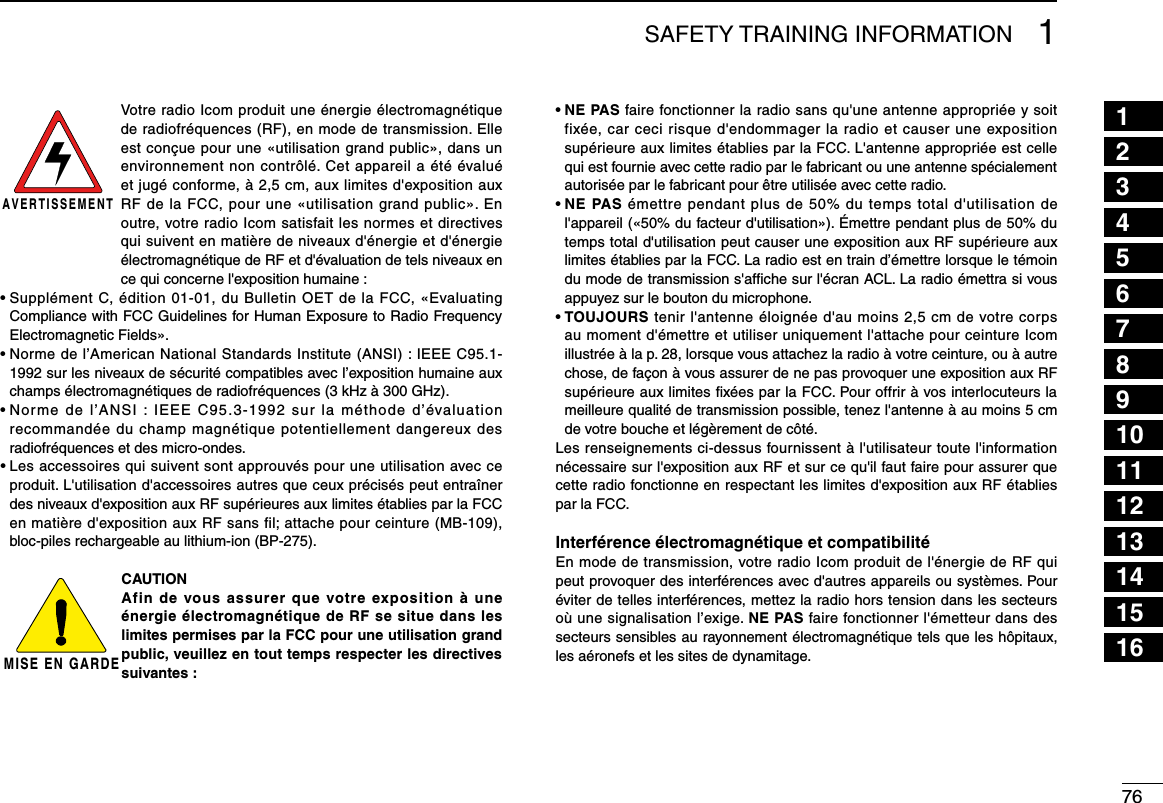
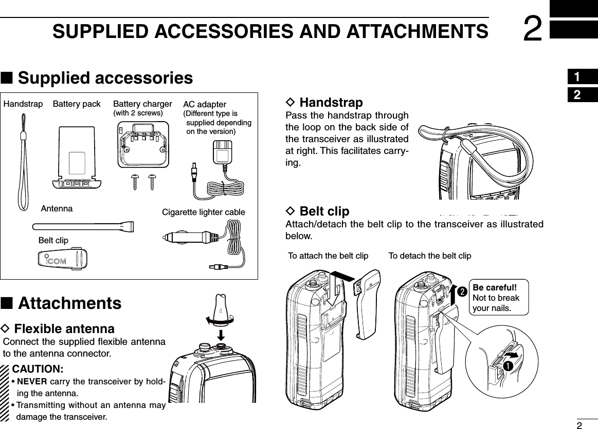
![iiiIN CASE OF EMERGENCYIf your vessel requires assistance, contact other vessels and the Coast Guard by sending a distress call on Channel 16.Or, transmit your Distress call using digital selective calling on Channel 70.USING CHANNEL 16DISTRESS CALL PROCEDURE1. “MAYDAY MAYDAY MAYDAY.”2. “THIS IS ...............” (name of vessel).3. Say your call sign or other indication of the vessel (AND 9-digit DSC ID if you have one).4. “LOCATED AT ...............” (your position).5. State the nature of the distress and assistance re-quired.6. Give any other information which might facilitate the rescue.USING DIGITAL SELECTIVE CALLING (Ch 70)DISTRESS CALL PROCEDURE1. While lifting up the key cover, push and hold [DISTRESS] for 3 seconds until you hear 3 short beeps change to one long beep.2. Wait for an acknowledgment on Channel 70 from a coast station. •Aftertheacknowledgementis received,Channel16 isautomatically selected.3. Push and hold [PTT], then transmit the appropriate infor-mation as listed above.](https://usermanual.wiki/ICOM-orporated/339400/User-Guide-1646032-Page-2.png)
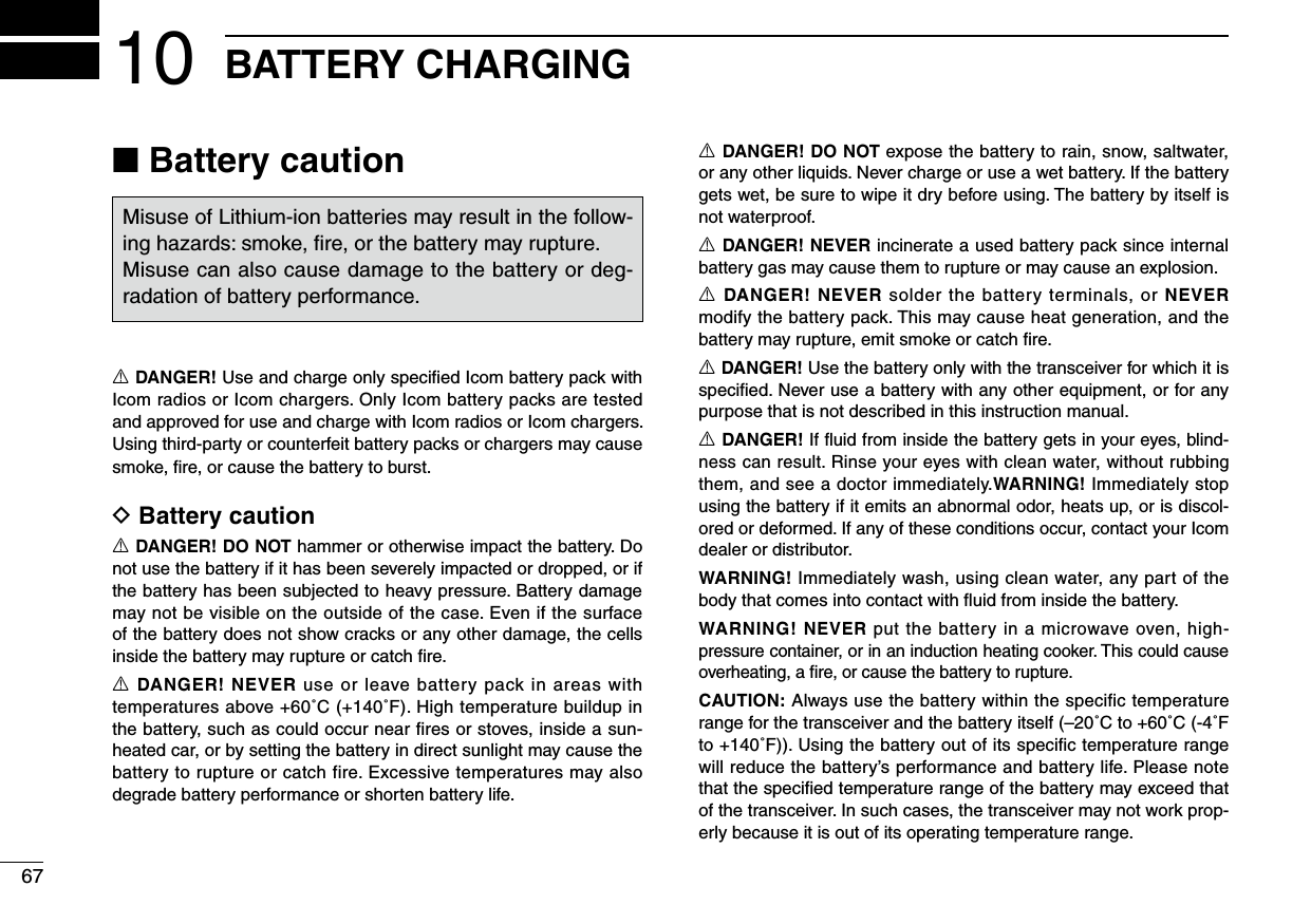
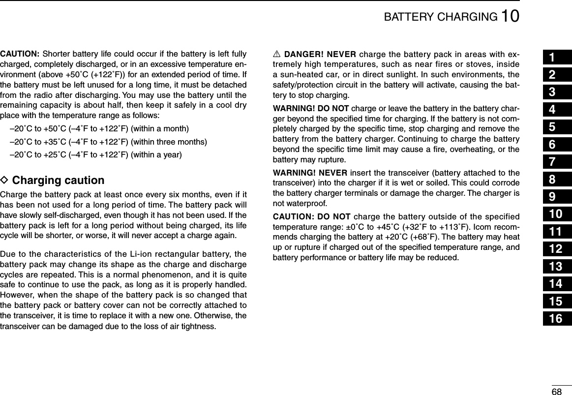
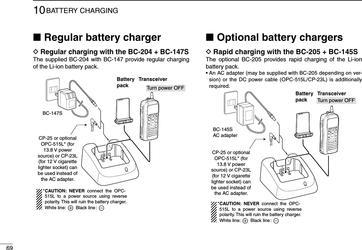
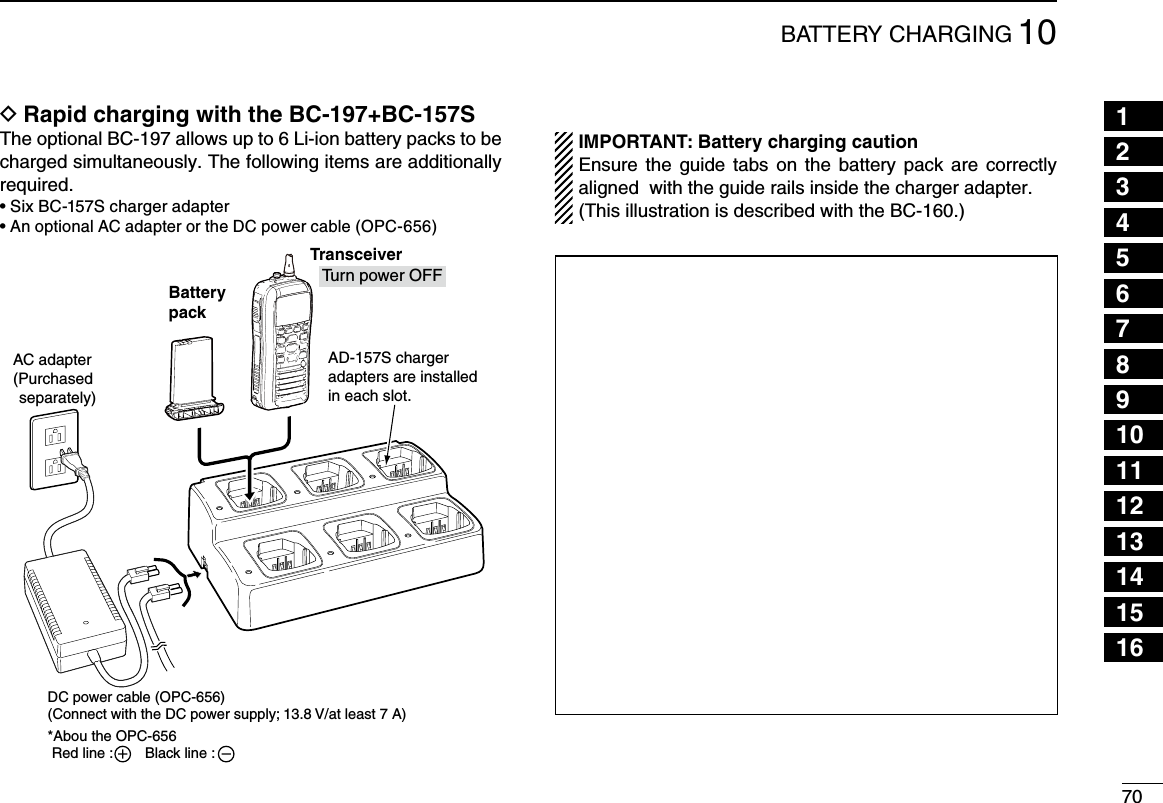
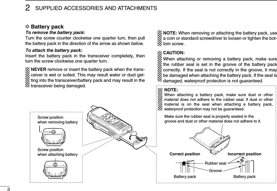
![3PRECAUTIONSCAUTION: MAKE SURE the flexible antenna, bat-tery pack and jack cover are securely attached to the trans-ceiver, and that the antenna and battery pack are dry before attachment. Exposing the inside of the transceiver to dust or water will result in serious damage to the transceiver.DO NOT operate the transceiver near unshielded electri-cal blast ing caps or in an explosive atmosphere.DO NOT push [PTT] when not actually intending to transmit.DO NOT use or place the transceiver in direct sunlight or in areas with temperatures below –20°C (–4°F) or above +60°C (+140°F).The basic operations, transmission and reception of the transceiver are guaranteed within the specified operating temperature range. However, the LCD display may not be operate correctly, or show an indication in the case of long hours of operation, or after being placed in extremely cold areas.DO NOT use harsh solvents such as benzine or alcohol when cleaning, as they will damage the transceiver surfaces.R WARNING! NEVER connect the transceiver to an AC outlet. This may pose a fire hazard or result in an electric shock.R WARNING! NEVER hold the transceiver so that the antenna is very close to, or touching exposed parts of the body, especially the face or eyes, while transmitting. The transceiver will perform best if the microphone is 5 to 10 cm (2 to 4 inches) away from the lips and the transceiver is verti-cal.R WARNING! NEVER operate the transceiver with other audio accessories at high volume levels. Hearing ex-perts advise against continuous high volume operation. If you experience a ringing in your ears, reduce the volume level or discontinue use.DO NOT modify the transceiver. The transceiver warranty does not cover any problems caused by unauthorized modification.BE CAREFUL! The transceiver will become hot when operating it continuously for long periods of time.KEEP the transceiver and microphone at least 1 m away from the vessel’s magnetic navigation compass.KEEP the transceiver out of the reach of children.](https://usermanual.wiki/ICOM-orporated/339400/User-Guide-1646032-Page-5.png)
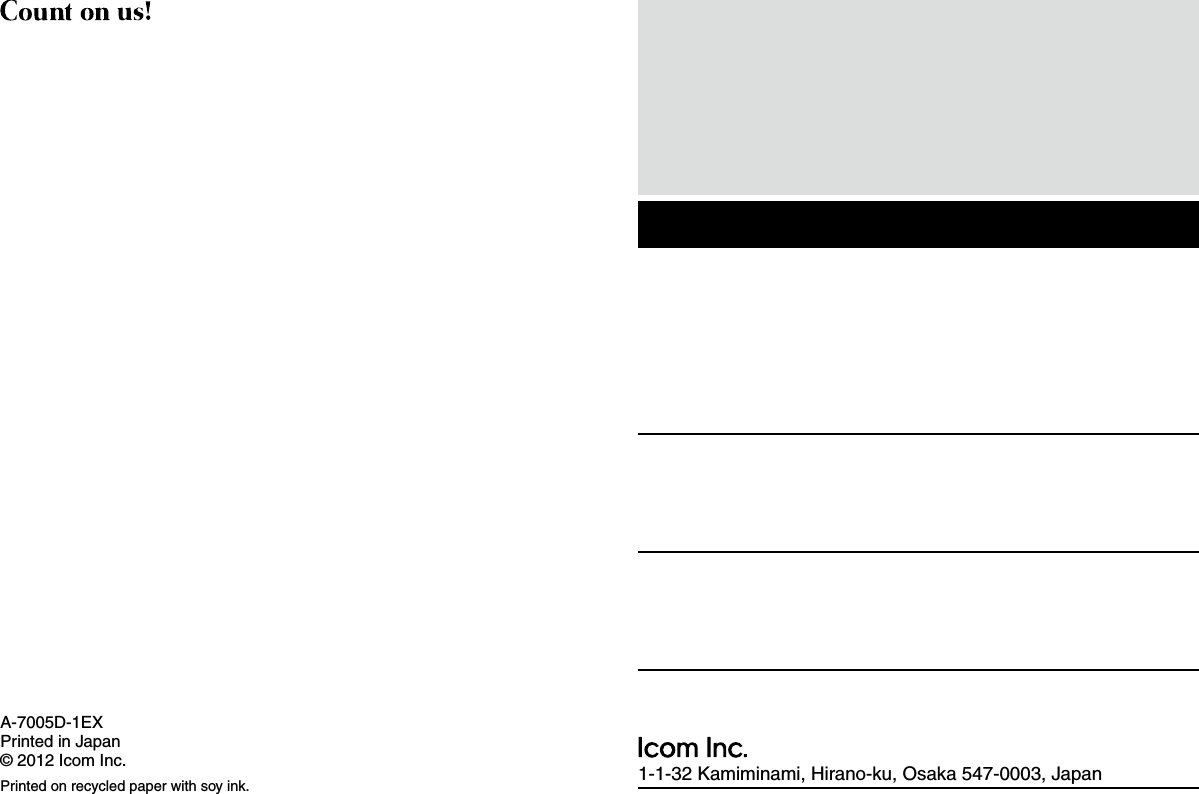
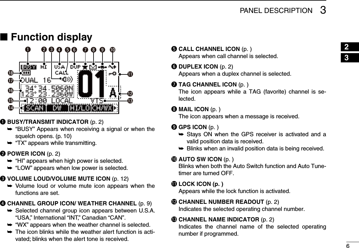
![43PANEL DESCRIPTION12345678910111213141516Front, top, side and rear panels ■Distress button(p. iii)Functiondisplay (pp. 6, 7)Microphonetreywq!0iuoSpeaker !1/+%q ANTENNA CONNECTOR (p. 2) Connects the supplied antenna.w SPEAKER-MICROPHONE CONNECTOR [SP MIC] (p. 25) Connects the optional external speaker-microphone. NOTE: Attach the [SP MIC] cap when the optional speaker-microphone is not used. Otherwise, water will get into the transceiver.e PTT SWITCH [PTT] Push and hold to transmit; release to receive. (p. 10)r MENU KEY Push to enter the Menu mode to select from the following menus: Adjustment Mode, Inspection Mode, DSC Calls, DSC Settings, Radio Settings, Configuration, MMSI/GPS Info, MOB, Waypoint or GPS Status.Continued on the next page.](https://usermanual.wiki/ICOM-orporated/339400/User-Guide-1646032-Page-11.png)
![53PANEL DESCRIPTIONFront, top and rear panels ■Distress button(p. iii)Functiondisplay (pp. 6, 7)Microphonetreywq!0iuoSpeaker !1/+%t VOLUME/SQUELCH KEY [VOL/SQL] Push to enter the volume adjustment mode. (pp. 11, ➥12) Push again while in the volume adjustment mode to ➥enter the squelch level adjustment mode.y SOFT MENU KEYS [1]/[2]/[3]/[4] Slide menu by pushing [Ω]/[≈] keys, then push either of the 4 keys to select a menu displayed above on the lower side of the monitor.u CHANNEL UP/DOWN [Y]/[Z] AND LEFT/RIGHT [Ω]/[≈] KEYSPush ➥ [Y]/[Z] to select an operating channel. (p. ) While in the set mode, selects the setting or value of ➥an item.i CLEAR/LOCK KEY [ ] Push to clear the selected page and return to the previ- ➥ous screen. Hold down for 1 second to turn the key lock function ON ➥or OFF. (p. 13)o ENTER KEY Push to select a function, enter the input channel com-ment, select an item, etc.!0 CHANNEL 16 KEY [16/C]Push to select Channel 16. (p. 8) ➥ Hold down for 1 sec. to select the call channel. (p. 8) ➥ When the call channel is selected, hold down for 3 sec. ➥to enter the call channel programming mode. (p. 11) While in the set mode, push to return to the normal ➥condition. (p. 17)!1 POWER KEY [ ] Hold down for 1 second to turn the power ON or OFF.](https://usermanual.wiki/ICOM-orporated/339400/User-Guide-1646032-Page-12.png)
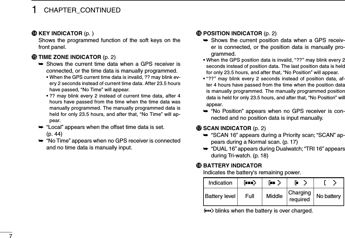
![84PREPARATION12345678910111213141516MMSI code programming ■The 9 digit MMSI (Maritime Mobile Service Identity: DSC self ID) code can be programmed at power ON. NOTE: •This initial code programming can be performed only the first time to turn the power ON. •Theprogrammingcanonlybedoneonce. •After the programming is completed, it can be re-pro-grammed only by your dealer or distributor.First, push q [ ] turn ON the power. •Theopeningdisplayappears. •“MMSI” display appears and warning alarm sounds for 2 seconds. “Push [ wENT] to Register Your MMSI” appears. •Donotpush[CLEAR] while this screen is displayed. Push e[Y]/[Z]/[Ω]/[≈] to select and input with [ENTER]. r Select “FINISH” and push [ENTER] to register. t When “MMSI CONFIRMATION” screen appears, input the previously registered 9 digited code to confirm the regis-tration. Then, push [ENTER] to register. •Automatically enters the functional mode if the registration isvalid. MMSI code check DThe 9 digit MMSI code can be checked.Push q[MENU]. Push w[Y]/[Z] several times to select “MMSI/GPS Info”, then push [ENTER] to enter. Select “ eEXIT” to return to the main menu screen or “BACK” to return to the previous screen.](https://usermanual.wiki/ICOM-orporated/339400/User-Guide-1646032-Page-15.png)
![95BASIC OPERATIONChannel selection ■ IMPORTANT: Prior to using the transceiver for the first time, the battery pack must be fully charged for optimum life and operation. To avoid damage to the transceiver, turn the power OFF while charging.Channel 16 DChannel 16 is the distress and safety channel. It is used for establishing initial contact with a station and for emergency communications. Channel 16 is monitored during both Du-al-watch and Tri-watch. While in the standby condition, you must monitor Channel 16.Push q[16/C] to select Channel 16. •“CALLING”appears. Select w[CH/WX] to return to the selected channel before Channel 16, or push [Y]/[Z] to select an operating chan-nel.Push [16/C] keyCall channel DEach regular channel group has separate leisure-use call channels. The call channel is monitored during Tri-watch. The call channels can be programmed (p. 11) and are used to store your most often used channel in each channel group for quick recall.Hold down q[16/C] for 1 second to select Call channel. •“CALLING”andthecallchannelnumberappear. •Callchannelcanbere-programmed.Seethe“Callchannelpro-gramming” on page 10 for details. Select w“CH/WX” to return to the selected channel before the call channel, or push [Y]/[Z] to select the operating channel.Hold down [16/C] key for 1 second](https://usermanual.wiki/ICOM-orporated/339400/User-Guide-1646032-Page-16.png)
![105BASIC OPERATION12345678910111213141516U.S.A., International and Canadian channels DThe transceiver is pre-programmed with 59 U.S.A., 59 Inter-national and 63 Canadian channels. These channel groups may be specified for the operating area.Push [ qMENU]. Push w[Y]/[Z] to select “Radio Settings”. •U.S.A.,InternationalandCanadianchannelgroupscanbese-lected in sequence.Push e[Y]/[Z] to select “CHAN Group”.r Select between “USA”, “INT” and “CAN”.t Select “EXIT” while the desired channel group is selected to return to the home screen. •“DUP” appears for duplex channels.Weather channels DThe IC-M92D has 10 pre-programmed weather channels.These are used for monitoring broadcasts from NOAA (Na-tional Oceanographic and Atmospheric Administration.)The transceiver can automatically detect a weather alert tone on the selected weather channel while receiving on another channel, during standby on a regular channel or while scan-ning. (p. 44)To Select a Weather channel:Select “CH/WX” to select a weather channel.•“WX”appearswhenaweatherchannelisselected.•Weather channel alert icon appears when the alert function isturned ON. To set the Weather Alert:Push q[MENU]. Push w[Y]/[Z] to select “Radio Settings”. Push e[Y]/[Z] to select “WX Alert”.r Select “ON” to set the Weather Alert. .t Select “EXIT” while “ON” is selected to return to the home screen. •WX Alert icon appears.](https://usermanual.wiki/ICOM-orporated/339400/User-Guide-1646032-Page-17.png)
![115BASIC OPERATIONReceiving and transmitting ■ CAUTION: Transmitting without an antenna may damage the transceiver.Hold down q[] for 1 second to turn power ON.Set the volume and squelch levels with w[VOL/SQL]. Set the volume by pushing ➥[Y]/[Z] to adjust the vol-ume. Set the squelch level by pushing ➥[VOL/SQL] while the volume adjustment mode is selected. •While in the squelch adjustment mode, pushing [Y] will make the noise disappear.Push e[Y]/[Z] to select the desired channel. •Further adjustment of the audio may be necessary at thispoint.r Select “HI/LO” to select the output power if necessary. •“HI”appearswhenhighpowerisselected;“LOW”whenhighpower is selected. •Choose low power for short range communications, choosehigh power for longer distance communications. •Somechannelsareforlowpoweronly.t Hold down [PTT] to transmit, then speak into the micro-phone. •Channel70cannotbeusedfortransmission.t Release [PTT] to receive. IMPORTANT: To maximize the readability of your trans-mitted signal, pause a few seconds after pushing [PTT], hold the microphone 5 to 10 cm (2 to 4 inches) from your mouth and speak into the microphone at a normal voice level. NOTE: The transceiver has a power save function to con-serve the battery power. The power save function activates automatically when no signal is received for 5 seconds. For U.S.A. version: To prevent accidental prolonged transmission, etc., the transceiver has a time-out timer function. This timer cuts a transmission OFF after 5 min-utes of continuous transmission.](https://usermanual.wiki/ICOM-orporated/339400/User-Guide-1646032-Page-18.png)
![125BASIC OPERATION12345678910111213141516Call channel programming ■Call channel is used to access the Call Channel 9 (default), however, you can program the call channel with your most often-used channels in each channel group for quick recall. Select the qdesired channel group (U.S.A, International or Canada) to be programmed. (p. ) Hold down w[16/C] for 1 second to select the call channel of the selected channel group. •“CALLING” and call channel number appear. Hold down e[16/C] again until long beep stops with two short beeps. The channel programming mode screen is displayed.r Push [Y]/[Z] to select the desired channel.t Push [ENTER] to program the selected channel as the call channel. •Thedisplayautomaticallyreturnstothemainmenuscreen.Adjusting the volume level ■The volume level can be adjusted with [VOL/SQL] and [Y]/[Z] keys. Push q[VOL/SQL] once to enter the volume adjustment mode, then adjust the volume level with [Y]/[Z].• The transceiver has 20 volume levels and OFF. •Withnokeyoperationisperformedfor5seconds,itreturnstothe main menu. Push w[VOL/SQL] twice to exit the volume adjustment mode.Adjusting the squelch level ■The squelch level can be adjusted with [VOL/SQL] and [Y]/[Z] keys.In order to receive signals properly, as well as for the scan to function effectively, the squelch must be adjusted to its proper level. Push q[VOL/SQL] twice to enter the squelch adjustment mode, then adjust the squelch level with [Y]/[Z]. •Thetransceiverhas11squelchlevels:OPiscompletelyopen;10 is tight squelch; 1 is loose squelch. •Withnokeyoperation isperformedfor5seconds,thetrans-ceiver returns to the main screen. Push w[VOL/SQL] again to exit the adjustment mode and return to the main menu screen.](https://usermanual.wiki/ICOM-orporated/339400/User-Guide-1646032-Page-19.png)
![135BASIC OPERATIONVolume loud function ■The volume loud function can be activated temporarily by pushing [VOL/SQL] and [Y]. The function does not work when the volume level is al-ready set to the maximum 20. Hold down q[VOL/SQL] first, and then while holding it down, push [Y] to activate the volume loud function. •Thevolumelevelissettothemaximumlevel(level20). •Thevolumeiconappears.Push w[ENTER] to turn the volume function OFF. Volume mute function ■The volume mute function can be activated temporarily by pushing [VOL/SQL] and [Z]. The function does not work when the volume level is al-ready OFF. Hold down q[VOL/SQL] first, and then while holding it down, push [Z] to activate the volume loud function. •Thevolumelevelissettotheminimumlevel(OFF). •Volumemuteiconappears.Push w[ENTER] to turn the volume mute function OFF. The volume mute or volume loud icon appears.](https://usermanual.wiki/ICOM-orporated/339400/User-Guide-1646032-Page-20.png)
![145BASIC OPERATION12345678910111213141516Lock function ■This function electronically locks all keys (except for [PTT] and [ ]) to prevent accidental channel changes and function access. Push ➥[CLEAR/ ] for 1 second to turn the lock function ON and OFF. Appears while the lock function is activated.Monitor function ■This function lights the function display and keys, and it is convenient for night-time operation. The automatic backlight-ing can be set in the set mode. (p. 19) Push any key except for ➥[PTT] to turn the backlight ON. •Thebacklightis automaticallyturnedOFF after 5secondsofinactivity.AquaQuake water draining ■ functionThe AquaQuake water draining function clears water away from the speaker grill. Without this function, water may muffle the sound coming from the speaker. The transceiver emits a vibrating beep when this function is activated.Select ➥“AQUA” and hold down the soft key. •Abeepsoundsfor10secondstodrainwater,regardlessofthevolume level setting. •Thetransceiver neveracceptskeyoperationwhiletheAqua-Quake function is activated. •TheAquaQuakefunctioncannotbeactivatedwhenanoptionalspeaker-microphone is connected.](https://usermanual.wiki/ICOM-orporated/339400/User-Guide-1646032-Page-21.png)
![155BASIC OPERATIONSetting TAG channels ■For more efficient scanning, add the desired channels as TAG channels or clear TAG for unwanted channels. Chan-nels that are not tagged will be skipped during scanning. TAG channels can be assigned to each channel group (U.S.A., International and Canada) independently.Select q“CH/WX” to select the desired channel group. While the desired channel is selected on the display, se- wlect the TAG icon on the soft keys. •“” appears on the display. To cancel a TAG channel setting, select the desired TAG echannel, then select the TAG icon on the soft keys. •“” disappears.To Clear (or set) all tagged channels:Hold down to select TAG for 3 seconds on the soft keys until a short beep sounds. This clears all tags or tag all channels. Channel names ■Each channel can be labeled with alphanumeric names of up to 10 characters for easy channel recognition. The programmed names will be indicated at the chan- ➥nel name indicator of the function display. Capital letters, numbers, 26 types of symbols and ➥space can be used.Select the desired channel. q •Canceldualwatch,Tri-watchorScaninadvance. While the desired channel is displayed, select w“NAME” to enter the channel name edtting mode screen. Select the desired character by pushing e[Y]/[Z]/[Ω]/[≈] keys, and then input with [ENTER]. •Whileinthechannelnameedittingmode,pushtheveryrightkey of the soft keys to change between alphabets, numers and symbols. •Select “DELETE” to delete the selected character and select “SPACE” to insert a space.r Select “FINISH” to program the name. •Automaticallyreturnstothemainmode. •Theprogrammednameappearsonthedsiplay.](https://usermanual.wiki/ICOM-orporated/339400/User-Guide-1646032-Page-22.png)
![165BASIC OPERATION12345678910111213141516Backlight setting ■This function lights the function display and keys, and it is convenient for night-time operation.Select q“BKLT” to enter the backlight adjusting mode. Push w[Y] or [Z] to adjust the brightness level between 1(minimum) to 7 (maximum) or OFF. •Thedefaultsettingis3. •Thedisplayreturnsautomaticallytothemainmanuafter5sec-onds without no key operation is been performed.](https://usermanual.wiki/ICOM-orporated/339400/User-Guide-1646032-Page-23.png)
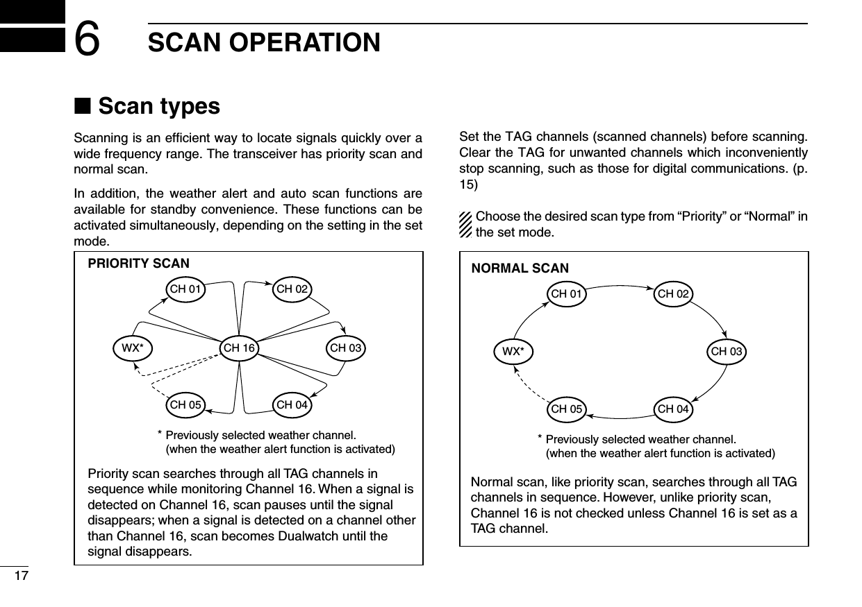
![186SCAN OPERATION12345678910111213141516Starting a scan ■Set the scan type (Priority or Normal scan), WX Alert function and Scan Timer function in advance, using the se mode.To select a scan type: Select the scan type between Normal scan and Priority scan.Push q [MENU]. Push w[Y] or [Z] to select “Radio Settings”, then push [EN-TER]. Select “ eScan Type”, then push [ENTER].r Select “Normal Scan” or “Priority Scan” and push [ENTER] to program.t Select “BACK” to return to the previous page, or simply select “EXIT” to return to the main menu screen. •“SCAN” appears if“Normal Scan” is selected, and “SCAN 16” apppears if “Priority Scan” is selected as show below.To scan: Select “SCAN” and push on the soft key to start or stop scan-ning. •Pushing[PTT] also stops the scan.•Whenasignalisreceived,scanpausesuntilthesignaldisappearsor resumes after pausing for 5 seconds according to the Scan Timer setting.•While scanning, push [Y] or [Z] to check which channels have been set as TAG channels or to change the scanning direction.](https://usermanual.wiki/ICOM-orporated/339400/User-Guide-1646032-Page-25.png)
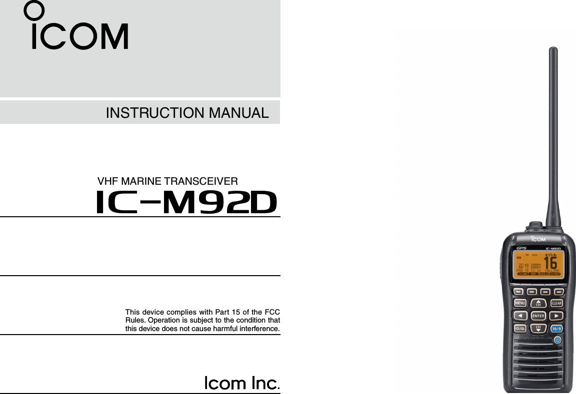
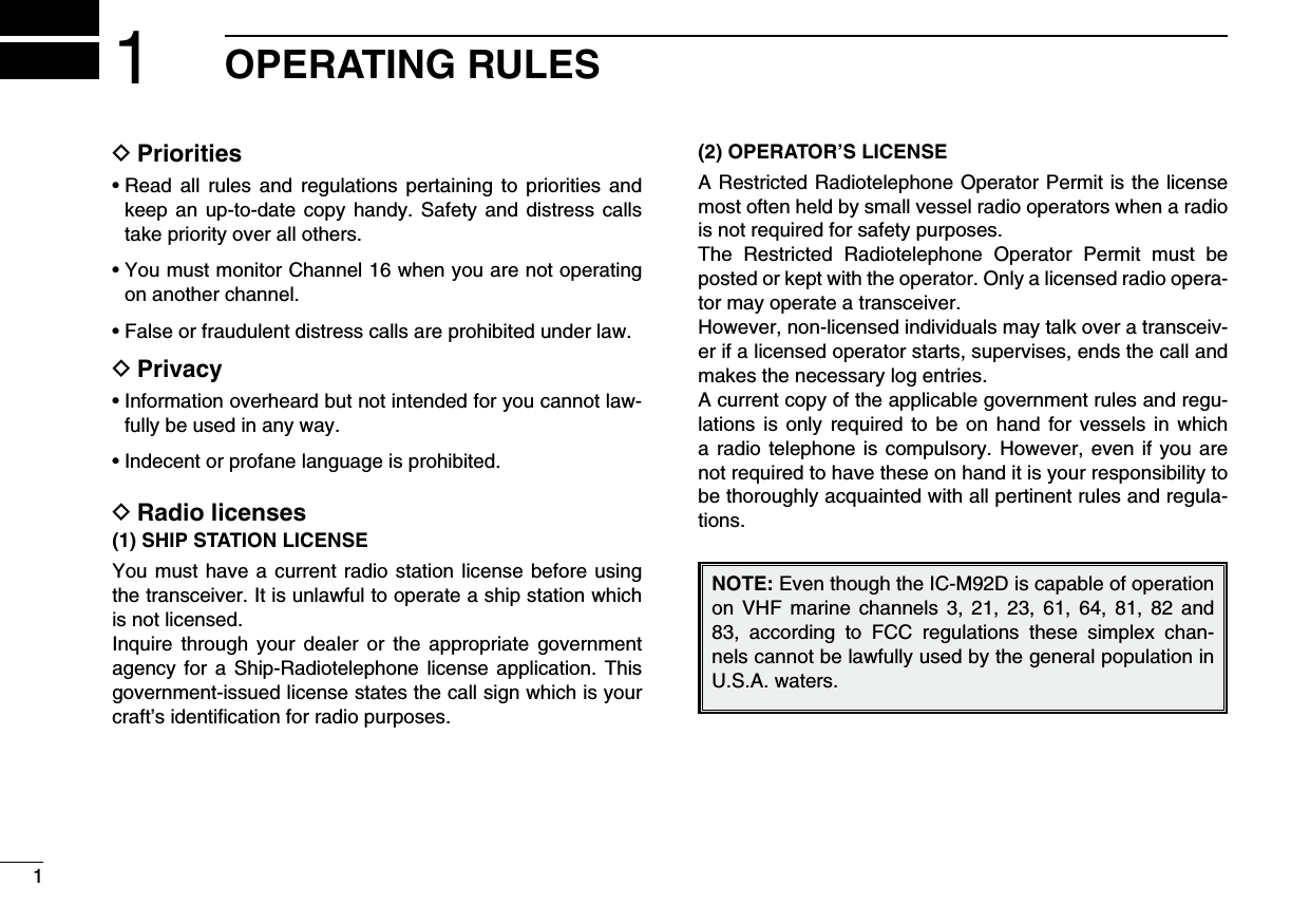
![197DUALWATCH/TRI-WATCHDescription ■Dualwatch monitors Channel 16 while you are receiving on another channel; Tri-watch monitors Channel 16 and the call channel while receiving another channel. Dualwatch/Triwatch is convenient for monitoring Channel 16 when you are oper-ating on another channel.DUALWATCH/TRI-WATCH SIMULATIONDualwatchTri-watchCallchannelCh 88Ch 16 Ch 88 Ch 16 Ch 88 Ch 9•IfasignalisreceivedonChannel16,Dualwatch/Tri-watchpauses on Channel 16 until the signal disappears.•IfasignalisreceivedonthecallchannelduringTri-watch,Tri-watch becomes Dualwatch until the signal disap-pears.•To transmit on the selected channel during Dualwatch/Tri-watch, hold down [PTT].Operation ■Push q [MENU]. Push w[Y] or [Z] to select “Radio Settings”, then push [EN-TER]. Select “ eDual/Tri-Watch”, then push [ENTER].r Select “Dualwatch” or “Tri-watch” and push [ENTER] to program.t Select “BACK” to return to the previous page, or simply select “EXIT” to return to the main menu screen. •“DUAL16”appearsif“Dualwatch” is selected, and “TRI 16” app-pears if “Tri-watch” is selected as shown below.DUAL 16 or TRI 16 appears, depending on the setting. Select to start Dualwatch or Tr i-watch.](https://usermanual.wiki/ICOM-orporated/339400/User-Guide-1646032-Page-26.png)
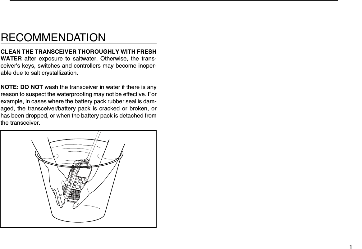
![208DSC OPERATION12345678910111213141516DSC address ID ■Programming Individual ID DA total of 100 DSC address IDs can be programmed and as-signed a name of up to 10 characters.Enter “INDIVIDUAL ID” in the DSC SETTINGS menu. qPush [ADD]. w •The“INDIVIDUALID”programscreenisdisplayed.Enter a desired individual ID in the following instruction: e •Selectadesirednumberusing[Y]/[Z]/[Ω]/[≈]. •Push[ENT]tosetit. •Tomovethecursor,selecteitherarrow,“←” or “→,” then push [ENT]. The first digit is specified as ‘0’ for a Group ID.The first two digits are ‘0’ for any Coast station ID.Repeat step r e to enter all 9 digits.After entering the 9 digit code, push [ENT] to set it. t •IDnameprogrammingscreenisdisplayed.Enter a desired 10 digit ID name in the following instruction: y •Selectadesiredcharacterusing[Y]/[Z]/[Ω]/[≈]. •Push[ENT]tosetit. •Tomovethecursor,selecteitherarrow,“←” or “→,” then push [ENT]. •Push[123]then[!$?]then[ABC]toselectacharactergroup. After entering the ID name, select “FINISH” by pushing u[Y]/[Z]/[Ω]/[≈], then push [ENT] to program it.The “INDIVIDUAL ID” list screen is displayed. i •Push[MENU]toexittheMENUscreen. MENU ➪ DSC Settings ➪ Individual ID (Push [MENU]) (Push [Y]/[Z], then push [ENT].)](https://usermanual.wiki/ICOM-orporated/339400/User-Guide-1646032-Page-27.png)
![218DSC OPERATIONProgramming Group ID DEnter “GROUP ID” in the DSC SETTINGS menu. q •WhennogroupIDisprogrammed,“NoID”isdisplayed.Inthiscase, push [MENU] to exit the MENU screen.Push [ADD]. w •The“GROUPID”programscreenisdisplayed.Enter a desired group ID in the following instruction: e •Selectadesirednumberusing[Y]/[Z]/[Ω]/[≈]. •Push[ENT]tosetit. •Tomovethecursor,selecteitherarrow,“←” or “→,” then push [ENT]. The first digit is fixed as ‘0’ for a Group ID.The first two digits are ‘0’ for any Coast station ID.Repeat step r e to input the specific 9 digits group code. After entering the 9 digit code, push [ENT] to set it. t •GroupIDnameprogrammingscreenisdisplayed.Enter a desired 10 digit ID name in the following instruction: y •Selectadesiredcharacterusing[Y]/[Z]/[Ω]/[≈]. •Push[ENT]tosetit. •Tomovethecursor,selecteitherarrow,“←” or “→,” then push [ENT]. •Push[123],[!$?]or[ABC]toselectacharactergroup. After entering the ID name, select “FINISH” pushing [ uY]/[Z]/[Ω]/[≈], then push [ENT] to program it. •The“GROUPID”listscreenisdisplayed.Push [MENU] to exit the MENU screen. i MENU ➪ DSC Settings ➪ Group ID (Push [MENU]) (Push [Y]/[Z], then push [ENT].)](https://usermanual.wiki/ICOM-orporated/339400/User-Guide-1646032-Page-28.png)
![228DSC OPERATION12345678910111213141516Deleting Individual/Group ID D Enter “INDIVIDUAL ID” or “GROUP ID” in the DSC SET- qTINGS menu. •WhennoaddressIDisprogrammed,“NoID”isdisplayed.Inthis case, push [MENU] to exit the MENU screen. Select a desired ID name (or ID, if no name is programmed) wwith Dial or [Y]/[Z] to be deleted, then push [DEL]. Push [OK] to delete the ID, and return to the “INDIVIDUAL eID” or “GROUP ID” list screen. •Push[CANCEL]tocancelit.Push [MENU] to exit the MENU screen. r MENU ➪ DSC Settings ➪ Individual ID/Group ID (Push [MENU]) (Rotate Dial, then push [ENT].)](https://usermanual.wiki/ICOM-orporated/339400/User-Guide-1646032-Page-29.png)
![238DSC OPERATIONA Distress call should include the ship’s position and time data. If no GPS is connected, your position and UTC (Univer-sal Time Coordinated) time should be manually input. They are automatically included when a GPS receiver compatible with the NMEA0183 ver. 2.0 or 3.01 format is connected.•ManualprogrammingisdisabledwhenaGPSreceiverisconnected.•Manuallyprogrammedpositionandtimedatawillbeheldfor only 23.5 hours.Enter “POSITION INPUT” in the DSC SETTINGS menu. q Edit your latitude and longitude position data using Dial, or w[Y]/[Z]/[Ω]/[≈]. •SelectadesirednumberusingDial,or[Y]/[Z]/[Ω]/[≈]. •Push[ENT]orDialtosetit. •Tomovethecursor,selecteitherarrow,“←” or “→,” then push [ENT]. •SelectN:NorthlatitudeorS:Southlatitudewhenthecursorison the ‘N’ or ‘S’ position. •SelectW:WestlongitudeorE:Eastlongitudewhenthecursoris on the ‘W’ or ‘E’ position.After entering the position data, push [ENT] to program it. e The UTC time programming screen is displayed, enter the rUTC time in the following way: •Selectadesirednumberusing[Y]/[Z]/[Ω]/[≈]. •Push[ENT]tosetit. •Tomovethecursor,selecteitherarrow,“←” or “→,” then push [ENT]. Push [ENT] to program your position and time data. t •Returntothe“DSCSETTING”screen.Position and time programming ■ MENU ➪ DSC Settings ➪ Position Input (Push [MENU]) (Push [Y]/[Z], then push [ENT].)](https://usermanual.wiki/ICOM-orporated/339400/User-Guide-1646032-Page-30.png)
![241DSC OPERATION12345678910111213141516Distress call ■A Distress call should be transmitted if, in the opinion of the Master, the ship or a person is in distress and requires im-mediate assistance.NEVER MAKE A DISTRESS CALL IF YOUR SHIP OR A PERSON IS NOT IN AN EMERGENCY. A DISTRESS CALL SHOULD BE MADE ONLY WHEN IMMEDIATE HELP IS NEEDED.Simple call DConfirm no Distress call is being received. q While lifting up the key cover, hold down [DISTRESS] for 3 wseconds to transmit the Distress call. •While holding down [DISTRESS], count down beeps soundand both the key and display backlighting blink. •DSCchannel(Channel 70) isautomatically selected andtheDistress call is transmitted. After transmitting the call, the transceiver waits for an ac- eknowledgment call. •TheDistresscallisautomaticallytransmittedevery3.5to4.5minutes, until an acknowledgement is received (‘Call repeat’ mode), or DSC Cancel call is made (p. 26). •Push[RESEND]tomanuallytransmittheDistressrepeatcall. •Push[Ω]/[≈] then push [INFO] to display the transmitted Dis-tress call information. •Push [Ω]/[≈] then push [PAUSE] to pause the ‘Call repeat’ mode, push [RESUME] to resume it. After receiving the acknowledgment, push [ALARM OFF] rthen reply using the microphone.A distress alert contains (default): •Natureofdistress:Undesignateddistress •Positiondata :The latest GPS or manual input positiondata is held for 23.5 hours, or until the pow-er is turned OFF.](https://usermanual.wiki/ICOM-orporated/339400/User-Guide-1646032-Page-31.png)
![258DSC OPERATIONDistress cancel call D While waiting for an acknowledgment call, push [CAN- qCEL].Push [CONTINUE]. w •Push[BACK]toreturntowaitingforanacknowledgementcall.Push [FINISH]. e •Push[EXIT]toreturntowaitingforanacknowledgementcall.The Distress cancel call is transmitted. rChannel 16 is automatically selected. t •Reportyoursituationusingthemicrophone. •Afterthereport,push[EXIT]toreturntothenormaloperatingmode.](https://usermanual.wiki/ICOM-orporated/339400/User-Guide-1646032-Page-32.png)
![268DSC OPERATION12345678910111213141516Regular call DThe nature of the Distress call should be included in the Dis-tress call.Enter “DISTRESS CALL” in the DSC CALLS menu. q Select the nature of the distress using Dial or [ wY]/[Z], then push Dial or [ENT]. •‘Undesignated,’‘Fire,Explosion,’‘Flooding,’‘Collision,’‘Ground-ing,’ ‘Capsizing,’ ‘Sinking,’ ‘Adrift,’ ‘Abandoning ship,’ ‘Piracy’ or ‘Man Overboard’ is selectable. •Thenatureofthedistressisstoredfor10minutesafteraselec-tion is made.The Distress call confirmation screen is displayed. e •RotateDialorpush[Y]/[Z] to see the hidden lines. Hold down [DISTRESS] for 3 seconds to transmit the Dis- rtress call. •While holding down [DISTRESS], count down beeps soundand both the key and display backlight blink. •Theselectednatureofthedistressisstoredfor10minutes. MENU ➪ DSC Calls ➪ Distress Call (Push [MENU]) (Push [Y]/[Z], then push [ENT].)](https://usermanual.wiki/ICOM-orporated/339400/User-Guide-1646032-Page-33.png)
![278DSC OPERATIONTransmitting DSC calls ■To ensure correct operation of the DSC function, make sure you correctly set the CH70 SQL LEVEL. (p. 64)Transmitting an individual call DThe Individual call function allows you to transmit a DSC sig-nal to only a specific station.Enter “INDIVIDUAL CALL” in the DSC CALLS menu. q Select the desired preprogrammed individual address, or w“Manual Input,” using [Y]/[Z], then push [ENT]. •TheIDcodefortheIndividualcallcanbesetrst.(p.19) •When“ManualInput”isselected,setadesired9digitMMSIIDcode for the individual you wish to call. About Manual Inputting:Enter a desired individual ID in the following way:•Selectadesirednumberusing[Y]/[Z]/[Ω]/[≈].•Push[ENT]tosetit.•Tomovethecursor,selecteitherarrow,“←” or “→,” then push [ENT].•Therstdigitisspeciedas‘0’foraGroupID.•Thersttwodigitsare‘0’foranycoaststationID. Select Routine, Safety or Urgency as the desired call type eusing [Y]/[Z], then push [ENT].NOTE: When a coast station is selected in step w, the voice channel is automatically specified by the coast sta-tion. Therefore, skip step r and go directly to step t. ☞ Continued on the next page. MENU ➪ DSC Calls ➪ Individual Call (Push [MENU]) (Push [Y]/[Z], then push [ENT].)](https://usermanual.wiki/ICOM-orporated/339400/User-Guide-1646032-Page-34.png)
/[Z](CH), then push [ENT]. •Intershipchannelsarealreadypresetintothetransceiverintherecommended order.A confirmation screen appears. t •Conrmthecallcontents.Push [CALL] to transmit the Individual call. y •IfChannel70isbusy,thetransceiverstandsbyuntilthechan-nel becomes clear. Standby on Channel 70 until an acknowledgement is re- uceived. When the acknowledgement ‘Able to comply’ is received, ibeeps sound and the screen below is displayed. Or, when the acknowledgement ‘Unable to comply’ is re-ceived, beeps sound and the screen below is displayed. •Push[ALARMOFF]tostop thebeepsand thenreturntotheoperating channel (before you entered the MENU screen).](https://usermanual.wiki/ICOM-orporated/339400/User-Guide-1646032-Page-35.png)
![298DSC OPERATIONTransmitting an Individual Acknowledgement DWhen receiving an Individual call, you can transmit an ac-knowledgement (‘Able to Comply,’ ‘Propose New Channel’ or ‘Unable to Comply’) by using the on-screen prompts (Quick ACK.) Also, you can send an acknowledgement through the MENU system (Man ual ACK.)Quick ACK: When q an Individual call is received, beeps sound and the screen as shown below is displayed. Push [ALARM OFF] to stop the beeps.Push [ACK]. wSelect one of three options, then push [ENT]. e •AbletoComply :Makeanacknowledgmentcallwithoutany changes. •UnabletoComply :You cannot make an acknowledge-ment call. The Acknowledgement call (‘Unable to Comply’) can be automatically transmitted, if set. See page 61 for de-tails. •ProposeNewChannel:You can make an acknowledgementcall, but you specify the intership channel. Select a desired intership channel, using Dial, or [Y](CH)/[Z](CH), then push [ENT].](https://usermanual.wiki/ICOM-orporated/339400/User-Guide-1646032-Page-36.png)
![308DSC OPERATION12345678910111213141516The Individual ACK confirmation screen is displayed. r Push [CALL] to transmit an acknowledgement call.Following screens as shown below are displayed. tComply to the call using the microphone. yPush [EXIT] to return to the normal operating mode. uManual ACK:Enter “INDIVIDUAL ACK” in the DSC CALLS menu. q •When no Individual call has been received, “Individual ACK”item will not be displayed. Select a desired individual address or ID code to reply to, wusing Dial or [Y]/[Z], then push [ENT]. Perform steps e e to u, as described in “Quick ACK:” to the left.](https://usermanual.wiki/ICOM-orporated/339400/User-Guide-1646032-Page-37.png)
![311CHAPTER_CONTINUEDTransmitting a Group call DThe Group call function allows you to transmit a DSC signal to only a specific group.Enter “GROUP CALL” in the DSC CALLS menu. q Select the desired preprogrammed group address or w“Manual Input,” using [Y]/[Z], then push [ENT]. •TheIDcodefortheGroupcallcanbesetrst.(p.20) •When“ManualInput”isselected,setthe8digitIDcodeforthegroup you wish to call. Select a desired intership channel using [ eY](CH)/[Z](CH), then push [ENT]. •Intershipchannelsarealreadypresetintothetransceiverintherecommended order.About Manual Inputting:Enter a desired group ID in the following way:•Selectadesirednumberusing[Y]/[Z]/[Ω]/[≈].•Push[ENT]tosetit.•Tomovethecursor,selecteitherarrow,“←” or “→,” then push [ENT].•Therstdigitisspeciedas‘0’foraGroupID.•Thersttwodigitsare‘0’foranyCoaststationID.A confirmation screen appears. r •Conrmthecallcontents. MENU ➪ DSC Calls ➪ Group Call (Push [MENU]) (Push [Y]/[Z], then push [ENT].)](https://usermanual.wiki/ICOM-orporated/339400/User-Guide-1646032-Page-38.png)
![328DSC OPERATION12345678910111213141516Push [CALL] to transmit the Group call. t •IfChannel70isbusy,thetransceiverstandsbyuntilthechan-nel becomes clear. After the Group call has been transmitted, the following yscreen is displayed.Announce the information using the microphone. u After the announcement, push [EXIT] to return to the nor- imal operating mode.](https://usermanual.wiki/ICOM-orporated/339400/User-Guide-1646032-Page-39.png)
![338DSC OPERATIONTransmitting an All Ships call DAll ships, that have DSC transceiver, use Channel 70 as their ‘listening channel.’ When you want to announce a message to these ships within range, use the ‘All Ships Call’ function.Enter “ALL SHIPS CALL” in the DSC CALLS menu. q Select a desired category, using [ wY]/[Z], then push [ENT]. •The selectable categories may differ, depending on the pro-grammed setting. Ask your dealer for the selectable catego-ries. Select a desired traffic channel, using [ eY]/[Z], then push [ENT]. •Theselectedchannelisdisplayed.A confirmation screen appears. r •Conrmthecallcontents.Push [CALL] to transmit the All Ships call. t •IfChannel70isbusy,thetransceiverstandsbyuntilthechan-nel becomes clear. After the All Ships call has been transmitted, the following yscreen is displayed.Announce the message using the microphone. u After the announcement, push [EXIT] to return to the nor- imal operating mode. MENU ➪ DSC Calls ➪ All Ships Call (Push [MENU]) (Push [Y]/[Z], then push [ENT].)](https://usermanual.wiki/ICOM-orporated/339400/User-Guide-1646032-Page-40.png)
![348DSC OPERATION12345678910111213141516Transmitting a Position request call DTransmit a Position request call when you want to know a specific ship's current position.Enter “POSITION REQUEST” in the DSC CALLS menu. q Select the desired preprogrammed Position request ad- wdress or “Manual Input,” using [Y]/[Z], then push [ENT]. •TheIDcodeforthePositionrequestcallcanbesetrst. (p. 20) •When“ManualInput”isselected,setthe8digitIDcodeforthegroup you wish to call. About Manual Inputting: Enter a desired address ID in the following way: •Selectthedesirednumberusuing[Y]/[Z]/[Ω]/[≈]. •Push[ENT]tosetit. •Tomovethecursor,selecteitherarrow,“←” or “→,” then push [ENT]. •Therstdigitisspeciedas‘0’foraGroupID. •Thersttwodigitsare‘0’foranyCoaststationID.A confirmation screen appears. e •Conrmthecallcontents.☞ Continued on the next page. MENU ➪ DSC Calls ➪ All Ships Call (Push [MENU]) (Push [Y]/[Z], then push [ENT].)](https://usermanual.wiki/ICOM-orporated/339400/User-Guide-1646032-Page-41.png)
![398DSC OPERATIONTransmitting a Position Reply call DTransmit a Position Reply call when a Position Request call is received.When the “POSITION ACK” in DSC Settings is set to ‘Auto TX’ (p. 61), the transceiver automatically transmits a reply call when receiving a Position Request call.Quick Reply: When q a Position Request call is received, beeps sound and the screen as shown below is displayed. Push [ALARM OFF] to stop the beeps.Push [ACK]. w •Push[INFO]todisplaythePositionRequestcallinformation. Push [BACK] to return to the previous screen, or push [ACK].The Position Reply confirmation screen is displayed. e Push [CALL] to transmit the reply call. While transmitting the reply call, the screen as shown be- rlow is displayed, and then returns to the normal operating mode.](https://usermanual.wiki/ICOM-orporated/339400/User-Guide-1646032-Page-43.png)
![408DSC OPERATION12345678910111213141516Manual Reply:Enter “POSITION REPLY” in the DSC CALLS menu. q •IfnoPositionRequestcallhasbeenreceived,the“POSITIONREPLY” item will not be displayed. Select a desired Position Request call to reply to, using w[Y]/[Z], then push [ENT].The Position Reply call confirmation screen is displayed. e Push [CALL] to transmit the acknowledgement call. While transmitting the reply call, the screen as shown be- rlow is displayed, and then returns to the normal operating mode.When no GPS receiver is connected, and both position and time have been manually programmed, the screen as shown below appears. Edit your latitude and longitude posi-tion and UTC time data as follows: Push [CHG], then edit your latitude and longitude position and UTC time data. •Selectadesirednumberusing[Y]/[Z]/[Ω]/[≈]. •Push[ENT]tosetit. •Tomovethecursor,selecteitherarrow,“←” or “→,” then push [ENT]. •SelectN:NorthlatitudeorS:Southlatitudewhenthecursoris on the ‘N’ or ‘S’ position. •SelectW:WestlongitudeorE:Eastlongitudewhenthecur-sor is on the ‘W’ or ‘E’ position. MENU ➪ DSC Calls ➪ Position Reply (Push [MENU]) (Push [Y]/[Z], then push [ENT].)](https://usermanual.wiki/ICOM-orporated/339400/User-Guide-1646032-Page-44.png)
![418DSC OPERATIONTransmitting a Position Report Reply call DTransmit a Position Report Reply call when a Position Report Request call is received.Quick Reply: When q a Position Report Request call is received, beeps sound and the screen as shown below is displayed. Push [ALARM OFF] to stop the beeps.Push [ACK]. w •Push[INFO]todisplaythePositionReportRequestcallinfor-mation. Push [BACK] to return to the previous screen, or push [ACK]. The Position Report Reply confirmation screen is dis- eplayed. Push [CALL] to transmit the reply call. While transmitting the reply call, the screen as shown be- rlow is displayed, and then returns to the normal operating mode.](https://usermanual.wiki/ICOM-orporated/339400/User-Guide-1646032-Page-45.png)
![428DSC OPERATION12345678910111213141516Manual Reply: Enter “POSITION REPORT REPLY” in the DSC CALLS qmenu. •IfnoPositionReportRequestcallhasbeenreceived,the“PO-SITION REPORT REPLY” item will not be displayed. Select a desired Position Report Request call to be re- wplied, using [Y]/[Z], then push [ENT]. The Position Report Reply call confirmation screen is dis- eplayed. Push [CALL] to transmit the acknowledgement call. While transmitting the reply call, the screen as shown be- rlow is displayed, and then returns to the normal operating mode. MENU ➪ DSC Calls ➪ Position Report Reply (Push [MENU]) (Push [Y]/[Z], then push [ENT].)](https://usermanual.wiki/ICOM-orporated/339400/User-Guide-1646032-Page-46.png)
![438DSC OPERATIONTransmitting a Polling Reply call DTransmit a Polling Reply call when a Polling Request call is received.When the “POSITION ACK” in DSC Settings is set to ‘Auto TX’ (p. 61), the transceiver automatically transmits a reply call when receiving a Polling Request call.Quick Reply: When q a Polling Request call is received, beeps sound and the screen as shown below is displayed. Push [ALARM OFF] to stop the beeps.Push [ACK]. w •Push[INFO]todisplaythePollingRequestcallinformation. Push [BACK] to return to the previous screen, or push [ACK].The ePolling Reply confirmation screen is displayed. Push [CALL] to transmit the reply call. While transmitting the reply call, the screen as shown be- rlow is displayed, and then returns to the normal operating mode.](https://usermanual.wiki/ICOM-orporated/339400/User-Guide-1646032-Page-47.png)
![448DSC OPERATION12345678910111213141516Manual Reply:Enter “POLLING REPLY” in the DSC CALLS menu. q •If no Polling Request call has been received, the “POLLINGREPLY” item will not be displayed. Select a desired Polling Request call to be replied, using w[Y]/[Z], then push [ENT]. The Position Polling Reply call confirmation screen is dis- eplayed. Push [CALL] to transmit the acknowledgement call. While transmitting the reply call, the screen as shown be- rlow is displayed, and then returns to the normal operating mode. MENU ➪ DSC Calls ➪ Polling Reply (Push [MENU]) (Push [Y]/[Z], then push [ENT].)](https://usermanual.wiki/ICOM-orporated/339400/User-Guide-1646032-Page-48.png)
![458DSC OPERATIONTransmitting a Test call DTesting on the exclusive DSC distress and safety calling channels should be avoided as much as possible. When test-ing on the distress/safety channel is unavoidable, you should indicate that these are test transmissions. Normally the test call would require no further communica-tions between the two stations involved.Enter “TEST CALL” in the DSC CALLS menu. q Select a desired preprogrammed individual address, or w“Manual Input,” then push [ENT]. •TheIDcodefortheIndividualcallcanbesetrst.(p.19) •When“ManualInput”isselected,setthe9digitMMSIIDcodefor the individual you wish to call.About Manual Inputting:Enter a desired address ID in the following way:•Selectadesirednumberusing[Y]/[Z]/[Ω]/[≈].•Push[ENT]tosetit.•Tomovethecursor,selecteitherarrow,“←” or “→,” then push [ENT].•Therstdigitisspeciedas‘0’foraGroupID.•Thersttwodigitsare‘0’foranyCoaststationID.A confirmation screen appears. e •Conrmthecallcontents. MENU ➪ DSC Calls ➪ Test Call (Push [MENU]) (Push [Y]/[Z], then push [ENT].)](https://usermanual.wiki/ICOM-orporated/339400/User-Guide-1646032-Page-49.png)
![468DSC OPERATION12345678910111213141516Push [CALL] to transmit the Test call. r •IfChannel70isbusy,thetransceiverstandsbyuntilthechan-nel becomes clear. After the Test call has been transmitted, the following tscreen is displayed. When the acknowledgement call is received, beeps sound yand the following screen is displayed. Push [ALARM OFF] to stop the beeps, and then the screen uas shown below is displayed.Push [EXIT] to return to the normal operating mode. i](https://usermanual.wiki/ICOM-orporated/339400/User-Guide-1646032-Page-50.png)
![478DSC OPERATIONTransmitting a Test Acknowledgement call DWhen the “TEST ACK” in DSC settings is set to ‘Auto TX’ (p. 61), the transceiver automatically transmits a reply call when receiving a Test call.Quick ACK: When q a Test call is received, beeps sound and the screen as shown below is displayed. Push [ALARM OFF] to stop the beeps.Push [ACK]. w •Push[INFO]todisplaytheTestcallinformation. Push [BACK] to return to the previous screen, or push [ACK].The Test ACK confirmation screen is displayed. e Push [CALL] to transmit the acknowledgement call. While transmitting the acknowledgement call, the screen ras shown below is displayed, and then returns to the nor-mal operating mode.](https://usermanual.wiki/ICOM-orporated/339400/User-Guide-1646032-Page-51.png)
![488DSC OPERATION12345678910111213141516Manual ACK:Enter “TEST ACK” in the DSC CALLS menu. q •IfnoTestcallhasbeenreceived,the“TESTACK”itemwillnotbe displayed. Select a desired Test call to reply to, using [ wY]/[Z], then push [ENT].The Test ACK confirmation screen is displayed. e Push [CALL] to transmit the acknowledgement call. While transmitting the acknowledgement call, the screen ras shown below is displayed, and then returns to the nor-mal operating mode. MENU ➪ DSC Calls ➪ Test ACK (Push [MENU]) (Push [Y]/[Z], then push [ENT].)](https://usermanual.wiki/ICOM-orporated/339400/User-Guide-1646032-Page-52.png)
![498DSC OPERATIONReceiving DSC calls ■Receiving a Distress Call DWhen a Distress Call is received:➥ The emergency alarm sounds.➥ “RCVD DISTRESS” pops up and the LCD backlight blinks.➥ Continue monitoring the current operating channel for 10 seconds. After that, the transceiver automatically switches to Channel 16. This action may differ, depending on the CH16 Switch setting. See page 62 for more details. Push [ALARM OFF] to stop the alarm and the backlight qblinking. Push either softkey to select a desired action. w [EXIT] ➥Push to return to the normal operating mode. •ThetransceiverexitstheDSCmode. •By pushing [PTT], the transceiver also exits the DSCmode. •“ ” continues to blink and the Call is stored in the Re-ceived Call Log. [INFO] ➥Push to display the Received call information. (p. 58) [CH 16] ➥ Push to switch the operating channel to Channel 16, and monitor Channel 16, as a coast station may require assistance. •Ifyouhaven’tpushedanykeywithin10seconds,theoper-ating channel automatically switches to Channel 16.](https://usermanual.wiki/ICOM-orporated/339400/User-Guide-1646032-Page-53.png)
![508DSC OPERATION12345678910111213141516Receiving a Distress Acknowledgement DWhen a Distress Acknowledgement to other ship is received:➥ The emergency alarm sounds.➥ “RCVD DISTRESS ACK” pops up and the LCD backlight blinks.➥ Continue monitoring the current operating channel for 10 seconds. After that, the transceiver automatically switches to Channel 16. This action may differ, depending on the CH16 Switch setting. See page 62 for more details. Push [ALARM OFF] to stop the alarm and the backlight qblinking. Push either softkey to select a desired action. w [EXIT] ➥Push to return to the normal operating mode. •ThetransceiverexitstheDSCmode. •By pushing [PTT], the transceiver also exits the DSCmode. •“ ” continues to blink and the Call is stored in the Re-ceived Call Log. [INFO] ➥Push to display the Received call information. (p. 58) [CH 16] ➥ Push to switch the operating channel to Channel 16, and monitor Channel 16, as a coast station may require assistance. •Ifyouhaven’tpushedanykeywithin10seconds,theoper-ating channel also switches to Channel 16.](https://usermanual.wiki/ICOM-orporated/339400/User-Guide-1646032-Page-54.png)
![518DSC OPERATION Receiving D a Distress Relay CallWhen a Distress Relay call is received:➥ The emergency alarm sounds.➥ “RCVD DISTRESS RELAY” pops up and the LCD back-light blinks.➥ Continue monitoring the current operating channel for 10 seconds. After that, the transceiver automatically switches to Channel 16. This action may differ, depending on the CH16 Switch setting. See page 62 for more details. Push [ALARM OFF] to stop the alarm and the backlight qblinking. Push either softkey to select a desired action. w [EXIT] ➥Push to return to the normal operating mode. •ThetransceiverexitstheDSCmode. •By pushing [PTT], the transceiver also exits the DSCmode. •“ ” continues to blink and the Call is stored in the Re-ceived Call Log. [INFO] ➥Push to display the Received call information. (p. 58) [CH 16] ➥ Push to switch the operating channel to Channel 16, and monitor Channel 16, as a coast station may require assistance. •Ifyouhaven’tpushedanykeywithin10seconds,theoper-ating channel also switches to Channel 16.](https://usermanual.wiki/ICOM-orporated/339400/User-Guide-1646032-Page-55.png)
![528DSC OPERATION12345678910111213141516Receiving D a Distress Relay AcknowledgementWhen a Distress Relay Acknowledgement is received:➥ The emergency alarm sounds.➥ “RCVD DIST RELAY ACK” pops up and the LCD backlight blinks.➥ Continue monitoring the current operating channel for 10 seconds. After that, the transceiver automatically switches to Channel 16. This action may differ, depending on the CH16 Switch setting. See page 62 for more details. Push [ALARM OFF] to stop the alarm and the backlight qblinking. Push either softkey to select a desired action. w [EXIT] ➥Push to return to the normal operating mode. •ThetransceiverexitstheDSCmode. •By pushing [PTT], the transceiver also exits the DSCmode. •“ ” continues to blink and the Call is stored in the Re-ceived Call Log. [INFO] ➥Push to display the Received call information. (p. 58) [CH 16] ➥ Push to switch the operating channel to Channel 16, and monitor Channel 16, as a coast station may require assistance. •Ifyouhaven’tpushedanykeywithin10seconds,theoper-ating channel also switches to Channel 16.NOTE: If a duplicate call is received within 1 hour after receiving the Distress Relay or Distress Relay Acknowl-edgement call, the alarm does not sound.](https://usermanual.wiki/ICOM-orporated/339400/User-Guide-1646032-Page-56.png)
![538DSC OPERATIONReceiving an Individual Call DWhen an Individual Call is received:➥ T he emergency alarm sounds for 2 minutes, depending on the received Category.➥ “RCVD INDIVIDUAL CALL” pops up. The LCD backlight blinks for 2 minutes, depending on the received Category. Push [ALARM OFF] to stop the alarm and the backlight qblinking. •Ifyouhaven’tpushed[ALARMOFF]within2minutes,thenextscreen automatically appears, depending on the received Cat-egory. Push either softkey to select a desired action. w [EXIT] ➥Push to ignore the Call and return to the normal operating mode. •ThetransceiverexitstheDSCmode. •TheCallisstoredintheReceivedCallLog. •“ ” continues to blink and the Call is stored in the Re-ceived Call Log. [INFO] ➥Push to display the Received call information. (p. 59) [ACK] ➥ Push to display the “INDIVIDUAL ACK” screen to re-ply to the Call, and select the channel specified by the calling station for voice communication, depending on your situation. See page 30 for details of the Individual Acknowledgement procedure.When “INDIVIDUAL ACK” is set to “Auto ACK (Unable),” the transceiver automatically replies to the Call. In that case, both the TX and RX calls are stored in the Transmit-ted and Received Call Logs.](https://usermanual.wiki/ICOM-orporated/339400/User-Guide-1646032-Page-57.png)
![548DSC OPERATION12345678910111213141516Receiving a Group Call DWhen a Group Call is received:➥ The emergency alarm sounds for 2 minutes, depending on the received Category.➥ “RCVD GROUP CALL” pops up. The LCD backlight blinks for 2 minutes, depending on the received Category. Push [ALARM OFF] to stop the alarm and the backlight qblinking. •Ifyouhaven’tpushed[ALARMOFF]within2minutes,thenextscreen automatically appears, depending on the received Cat-egory. Push either softkey to select a desired action. w [EXIT] ➥Push to ignore the Call and return to the normal operat-ing mode. •ThetransceiverexitstheDSCmode. •“ ” continues to blink and the Call is stored in the Re-ceived Call Log. [INFO] ➥Push to display the Received call information. (p. 59) [CH xx*] * xx is specified by the calling station. (Example: 08) ➥ Push to monitor the specified channel for an announce-ment from the calling station.](https://usermanual.wiki/ICOM-orporated/339400/User-Guide-1646032-Page-58.png)
![558DSC OPERATIONReceiving an All Ships Call DWhen an All Ships Call is received:➥ The emergency alarm sounds for 2 minutes, depending on the received Category.➥ “RCVD ALL SHIPS CALL” pops up. The LCD backlight blinks for 2 minutes, depending on the received Category. Push [ALARM OFF] to stop the alarm and the backlight qblinking. •Ifyouhaven’tpushed[ALARMOFF]within2minutes,thenextscreen automatically appears, depending on the received Cat-egory. Push either softkey to select a desired action. w [EXIT] ➥Push to ignore the Call and return to the normal operat-ing mode. •ThetransceiverexitstheDSCmode. •“ ” continues to blink and the Call is stored in the Re-ceived Call Log. [INFO] ➥Push to display the Received call information. (p. 59) [CH xx*] * xx is specified by the calling station. (Example: 16) ➥ Push to monitor the specified channel for an announce-ment from the calling station.](https://usermanual.wiki/ICOM-orporated/339400/User-Guide-1646032-Page-59.png)
![568DSC OPERATION12345678910111213141516Receiving a Geographical Area Call DWhen a Geographical Area Call (for the area you are in) is received:➥ The emergency alarm sounds for 2 minutes, depending on the received Category.➥ “RCVD GEOGRAPHICAL CALL” pops up. The LCD back-light blinks for 2 minutes, depending on the received Cat-egory. Push [ALARM OFF] to stop the alarm and the backlight qblinking. •Ifyouhaven’tpushed[ALARMOFF]within2minutes,thenextscreen automatically appears, depending on the received Cat-egory. Push either softkey to select a desired action. w [EXIT] ➥Push to ignore the Call and return to the normal operat-ing mode. •ThetransceiverexitstheDSCmode. •“ ” continues to blink and the Call is stored in the Re-ceived Call Log. [INFO] ➥Push to display the Received call information. (p. 59) [CH xx*] * xx is specified by the calling station. ➥ Push to monitor the specified channel for an announce-ment from the calling station.When no GPS receiver is connected or if there is a prob-lem with the connected receiver, all Geographical Area Calls are received, regardless of your position.](https://usermanual.wiki/ICOM-orporated/339400/User-Guide-1646032-Page-60.png)
![578DSC OPERATIONReceiving a Position Request Call DWhen a Position Request Call is received:➥ The emergency alarm sounds for 2 minutes.➥ “RCVD POS REQUEST” pops up. The LCD backlight blinks for 2 minutes. Push [ALARM OFF] to stop the alarm and the backlight qblinking. •Ifyouhaven’tpushed[ALARMOFF]within2minutes,thenextscreen automatically appears. Push either softkey to select a desired action. w [EXIT] ➥Push to ignore the Call and return to the normal operat-ing mode. •ThetransceiverexitstheDSCmode. •“ ” continues to blink and the Call is stored in the Re-ceived Call Log. [INFO] ➥Push to display the Received call information. (p. 59) [ACK] ➥ Push to display the “POSITION REPLY” screen and send a reply to the Call. (p. 39)When “POSITION ACK” is set to “Auto TX,” the transceiv-er automatically replies to the Call. In that case, both the TX and RX calls are stored in the Transmitted and Re-ceived Call Logs.](https://usermanual.wiki/ICOM-orporated/339400/User-Guide-1646032-Page-61.png)
![588DSC OPERATION12345678910111213141516Receiving a Position Report Call DWhen a Position Report Call is received:➥ The emergency alarm sounds for 2 minutes.➥ “RCVD POSITION REPORT” pops up. The LCD backlight blinks for 2 minutes. Push [ALARM OFF] to stop the alarm and the backlight qblinking. •Ifyouhaven’tpushed[ALARMOFF]within2minutes,thenextscreen automatically appears. Push either softkey to select a desired action. w [EXIT] ➥Push to ignore the Call and return to the normal operat-ing mode. •ThetransceiverexitstheDSCmode. •“ ” continues to blink and the Call is stored in the Re-ceived Call Log. [INFO] ➥Push to display the Received call information. (p. 59)](https://usermanual.wiki/ICOM-orporated/339400/User-Guide-1646032-Page-62.png)
![598DSC OPERATIOND Receiving a Polling Request callWhen a Polling Request call is received:➥ The emergency alarm sounds for 2 minutes.➥ “RCVD POLLING REQUEST” pops up. The LCD backlight blinks for 2 minutes. Push [ALARM OFF] to stop the alarm and the backlight qblinking. •Ifyouhaven’tpushed[ALARMOFF]within2minutes,thenextscreen automatically appears. Push either softkey to select a desired action. w [EXIT] ➥Push to ignore the Call and return to the normal operat-ing mode. •ThetransceiverexitstheDSCmode. •“ ” continues to blink and the Call is stored in the Re-ceived Call Log. [INFO] ➥Push to display the Received call information. (p. 58) [ACK] ➥ Push to display the “POLLING REPLY” screen to reply to the Call. (p. 43)When “POSITION ACK” is set to “Auto TX,” the transceiver automatically replies to the Call. In that case, both the TX and RX calls are stored in the Transmitted and Received Call Logs.](https://usermanual.wiki/ICOM-orporated/339400/User-Guide-1646032-Page-63.png)
![628DSC OPERATION12345678910111213141516D Receiving a Test CallWhen a Test Call is received:➥ The emergency alarm sounds for 2 minutes.➥ “RCVD TEST CALL” pops up. The LCD backlight blinks for 2 minutes. Push [ALARM OFF] to stop the alarm and the backlight qblinking. •Ifyouhaven’tpushed[ALARMOFF]within2minutes,thenextscreen automatically appears. Push either softkey to select a desired action. w [EXIT] ➥Push to ignore the Call and return to the normal operat-ing mode. •ThetransceiverexitstheDSCmode. •“ ” continues to blink and the Call is stored in the Re-ceived Call Log. [INFO] ➥Push to display the Received call information. (p. 58) [ACK] ➥ Push to display the “TEST ACK” screen to reply to the Call. (p. 37)When “TEST ACK” is set to “Auto TX,” the transceiver au-tomatically replies to the Call. In that case, both the TX and RX calls are stored in the Transmitted and Received Call Logs.](https://usermanual.wiki/ICOM-orporated/339400/User-Guide-1646032-Page-64.png)
![638DSC OPERATIONReceiving a Test Acknowledgement Call DWhen a Test Acknowledgement Call is received:➥ The emergency alarm sounds for 2 minutes.➥ “RCVD TEST ACK” pops up. The LCD backlight blinks for 2 minutes. Push [ALARM OFF] to stop the alarm and the backlight qblinking. •Ifyouhaven’tpushed[ALARMOFF]within2minutes,thenextscreen automatically appears. Push either softkey to select a desired action. w [EXIT] ➥Push to ignore the Call and return to the normal operat-ing mode. •ThetransceiverexitstheDSCmode. •“ ” continues to blink and the Call is stored in the Re-ceived Call Log.Transmitted Call log ■The transceiver automatically stores up to 50 transmitted calls, and the logs can be used as a supplement to your log-book. Enter “TX CALL LOG” in the DSC CALLS menu. q MENU ➪ DSC Calls ➪ Transmitted Call Log (Push [MENU]) (Push [p]/[q], then push [ENT].) Push [ wp] or [q] to select the desired item, then push [ENT].Push e[p] or [q] to scroll the message contents. To delete the displayed message, push [DEL]. r •Theconrmationscreenappears,thenpush[OK]todelete. Push [EXIT] to return to the normal operating mode. t](https://usermanual.wiki/ICOM-orporated/339400/User-Guide-1646032-Page-65.png)
![648DSC OPERATION12345678910111213141516Received Call log ■The transceiver automatically stores up to 50 distress mes-sages and 50 other messages, and the messages can be used as a supplement to your logbook.•“ ” blinks when there is an unread message. Distress message D Enter “RCVD CALL LOG” in the DSC CALLS menu. q MENU ➪ DSC Calls ➪ Received Call Log (Push [MENU]) (Push [p]/[q], then push [ENT].) Push [ wp] or [q] to select “Distress,” then push [ENT]. •Themessagesarestoredin“Distress,”ifitsformatspecieris‘Distress.’ Push [ ep] or [q] to select the desired item, then push [ENT]. •Themessageintheunopenedlehasnotbeenread.Push r[p]/[q] to scroll the message contents. To delete the displayed message, push [DEL]. t •Theconrmationscreenappears,thenpush[OK]todelete. Push [EXIT] to return to the normal operating mode. y](https://usermanual.wiki/ICOM-orporated/339400/User-Guide-1646032-Page-66.png)
![658DSC OPERATIONOther messages D Enter “RCVD CALL LOG” in the DSC Calls menu. q MENU ➪ DSC Calls ➪ Received Call Log (Push [MENU]) (Push [p]/[q], then push [ENT].) Push [ wp] or [q] to select “Other,” then push [ENT]. •Themessagesarestoredin“Other,”ifitsformatspecierisoth-er than ‘Distress.’ Push [ ep] or [q] to select the desired item, then push [ENT]. •Themessageintheunopenedlehasnotbeenread.](https://usermanual.wiki/ICOM-orporated/339400/User-Guide-1646032-Page-67.png)
![668DSC OPERATION12345678910111213141516DSC Settings ■D Position Input (See page 22)D Add Individual ID/Group ID (See pages 19, 20)D Delete Individual ID/Group ID (See page 21)D Automatic Acknowledgement These items set the Automatic Acknowledgement function to “Auto TX” or “Manual TX.”When an Individual, Position Request, Position Report, Poll-ing Request or Test Call is received, the transceiver auto-matically transmits an Individual Acknowledgement, Position Reply, Position Report Reply*, Polling Reply or Test Acknowl-edgement Call, respectively.*Only when the received Position Report call requires a reply.When “INDIVIDUAL ACK” is set to “Auto TX,” the trans-ceiver automatically transmits the Acknowledgment call including “Unable to Comply” (No Reason Given) after re-ceivng the Individual call. qEnter either “INDIVIDUAL ACK,” “POSITION ACK,” “TEST ACK” in the DSC Settings menu. MENU ➪ DSC Settings ➪ Individual ACK (Push [MENU]) (Push [p]/[q], then push [ENT].) MENU ➪ DSC Settings ➪ Position ACK MENU ➪ DSC Settings ➪ Test ACK Rotate Dial wto select “Auto TX” or “Manual TX,” then push [ENT]. •Push[BACK]tocancelandreturntotheDSCSettingsmenu.(default)(default)(default) Push [EXIT] to return to the normal operating mode. e](https://usermanual.wiki/ICOM-orporated/339400/User-Guide-1646032-Page-68.png)