ICOM orporated 339400 VHF Marine Transceiver User Manual IC 41S Instruction Manual
ICOM Incorporated VHF Marine Transceiver IC 41S Instruction Manual
User Manual
INSTRUCTION MANUAL
iM92D
VHF MARINE TRANSCEIVER
This device complies with Part 15 of the FCC
Rules. Operation is subject to the condition that
this device does not cause harmful interference.

iii
IN CASE OF EMERGENCY
If your vessel requires assistance, contact other vessels and
the Coast Guard by sending a distress call on Channel 16.
Or, transmit your Distress call using digital selective calling
on Channel 70.
USING CHANNEL 16
DISTRESS CALL PROCEDURE
1. “MAYDAY MAYDAY MAYDAY.”
2. “THIS IS ...............” (name of vessel).
3. Say your call sign or other indication of the vessel (AND
9-digit DSC ID if you have one).
4. “LOCATED AT ...............” (your position).
5. State the nature of the distress and assistance re-
quired.
6. Give any other information which might facilitate the
rescue.
USING DIGITAL SELECTIVE CALLING (Ch 70)
DISTRESS CALL PROCEDURE
1. While lifting up the key cover, push and hold [DISTRESS]
for 3 seconds until you hear 3 short beeps change to one
long beep.
2. Wait for an acknowledgment on Channel 70 from a coast
station.
•Aftertheacknowledgementis received,Channel16 is
automatically selected.
3. Push and hold [PTT], then transmit the appropriate infor-
mation as listed above.
1
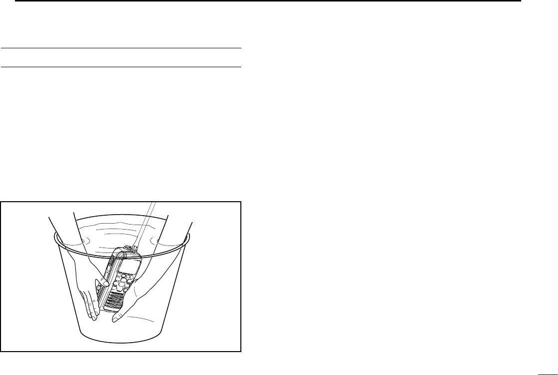
RECOMMENDATION
CLEAN THE TRANSCEIVER THOROUGHLY WITH FRESH
WATER after exposure to saltwater. Otherwise, the trans-
ceiver's keys, switches and controllers may become inoper-
able due to salt crystallization.
NOTE: DO NOT wash the transceiver in water if there is any
reason to suspect the waterproofing may not be effective. For
example, in cases where the battery pack rubber seal is dam-
aged, the transceiver/battery pack is cracked or broken, or
has been dropped, or when the battery pack is detached from
the transceiver.

2
FOREWORD
Thank you for purchasing this Icom product. The IC-M92D
v h f m a r i n e t r a n s c e i v e r is designed and built with Icom’s
state of the art technology and craftsmanship. With proper
care this radio should provide you with years of trouble-free
operation.
IMPORTANT
READ ALL INSTRUCTIONS carefully and com-
pletely before using the transceiver.
SAVE THIS INSTRUCTION MANUAL—This
instruction manual contains important operating instructions
for the IC-M92D.
This instruction manual includes some functions which are
usable only when they are pre-programmed by your dealer.
Ask your dealer for details.
EXPLICIT DEFINITIONS
WORD DEFINITION
RDANGER! Personal death, serious injury or an ex-
plosion may occur.
RWARNING! Personal injury, fire hazard or electric
shock may occur.
CAUTION Equipment damage may occur.
NOTE
If disregarded, inconvenience only. No risk
of personal injury, fire or electric shock.
FEATURES
☞

3
PRECAUTIONS
CAUTION: MAKE SURE the flexible antenna, bat-
tery pack and jack cover are securely attached to the trans-
ceiver, and that the antenna and battery pack are dry before
attachment. Exposing the inside of the transceiver to dust or
water will result in serious damage to the transceiver.
DO NOT operate the transceiver near unshielded electri-
cal blast ing caps or in an explosive atmosphere.
DO NOT
push [PTT] when not actually intending to transmit.
DO NOT use or place the transceiver in direct sunlight
or in areas with temperatures below –20°C (–4°F) or above
+60°C (+140°F).
The basic operations, transmission and reception of the
transceiver are guaranteed within the specified operating
temperature range. However, the LCD display may not be
operate correctly, or show an indication in the case of long
hours of operation, or after being placed in extremely cold
areas.
DO NOT use harsh solvents such as benzine or alcohol
when cleaning, as they will damage the transceiver surfaces.
R WARNING! NEVER connect the transceiver to an
AC outlet. This may pose a fire hazard or result in an electric
shock.
R WARNING! NEVER hold the transceiver so that
the antenna is very close to, or touching exposed parts of
the body, especially the face or eyes, while transmitting. The
transceiver will perform best if the microphone is 5 to 10 cm
(2 to 4 inches) away from the lips and the transceiver is verti-
cal.
R WARNING! NEVER operate the transceiver with
other audio accessories at high volume levels. Hearing ex-
perts advise against continuous high volume operation. If you
experience a ringing in your ears, reduce the volume level or
discontinue use.
DO NOT modify the transceiver. The transceiver warranty does
not cover any problems caused by unauthorized modification.
BE CAREFUL! The transceiver will become hot when
operating it continuously for long periods of time.
KEEP the transceiver and microphone at least 1 m away
from the vessel’s magnetic navigation compass.
KEEP the transceiver out of the reach of children.

4
FCC INFORMATION
BE CAREFUL! The IC-M92D meets IPX7* requirements
for dust-tight and waterproof protection. However, once the
transceiver has been dropped, dust-tight and waterproof pro-
tection cannot be guaranteed because of possible damage to
the transceiver’s case or the waterproof seal.
* Only when the jack cover or the optional HM-167 is at-
tached.
Even when the transceiver power is OFF, a slight current still
flows in the circuits. Remove the battery pack or batteries
from the trans ceiver when not using it for a long time. Other-
wise, the installed battery pack or batteries will become ex-
hausted, and will need to be recharged or replaced.
MAKE SURE to turn the transceiver power OFF before
connect ing the supplied/optional equipment.
For U.S.A. only:
CAUTION: Changes or modifications to this transceiver, not
expressly approved by Icom Inc., could void your authority to
operate this transceiver under FCC regulations.
PRECAUTIONS (Continued)
Icom, Icom Inc. and the Icom logo are registered trademarks of Icom Incor-
porated (Japan) in Japan, the United States, the United Kingdom, Germany,
France, Spain, Russia and/or other countries.
CAUTION: Changes or modifications to this device, not
expressly approved by Icom Inc., could void your authority to
operate this device under FCC regulations.
FOR CLASS B UNINTENTIONAL RADIATORS
This equipment has been tested and found to comply with
the limits for a Class B digital device, pursuant to part 15 of
the FCC Rules. These limits are designed to provide reason-
able protection against harmful interference in a residential
installation. This equipment generates, uses and can radiate
radio frequency energy and, if not installed and used in ac-
cordance with the instructions, may cause harmful interfer-
ence to radio communications. However, there is no guaran-
tee that interference will not occur in a particular installation.
If this equipment does cause harmful interference to radio
or television reception, which can be determined by turning
the equipment off and on, the user is encouraged to try to
correct the interference by one or more of the following mea-
sures:
•Reorientorrelocatethereceivingantenna.
•Increasetheseparationbetweentheequipmentandre-
ceiver.
•Connecttheequipmentintoanoutletonacircuitdifferent
from that to which the receiver is connected.
•Consultthedealeroranexperiencedradio/TVtechnician
for help.

5
TABLE OF CONTENTS
IN CASE OF EMERGENCY .................................................. i
RECOMMENDATION ............................................................ i
FOREWORD ........................................................................i
IMPORTANT .......................................................................... i
EXPLICIT DEFINITIONS ....................................................... i
FEATURES ............................................................................ i
PRECAUTIONS .................................................................... ii
FCC INFORMATION .............................................................i
TABLE OF CONTENTS ....................................................... iv
1 OPERATING RULES ...................................................1–5
2 SUPPLIED ACCESSORIES AND ATTACHMENTS ..6–13
3 PANEL DESCRIPTION ............................................14–19
4 PREPARATION........................................................20–26
5 BASIC OPERATION ......................................................27
6 SCAN OPERATION .................................................28–32
7 DUAL WATCH/TRI-WATCH .....................................33–34
8 DSC OPERATION ...................................................35–39
9 OTHER FUNCTION .................................................35–39
10 BATTEY CHARGING ..............................................35–39
11 OPTIONAL SPEAKER-MICROPHONE ..................35–39
12 MAINTENANCE ......................................................35–39
13 TROUBLE SHOOTING ............................................35–39
14 SPECIFICATIONS AND OPTIONS .........................35–39
15 VHF MARINE CHANNELLIST ................................35–39
16 SAFETY TRAINING INFORMATION .......................35–39

1
1OPERATING RULES
Priorities D
•Read all rules and regulations pertaining to priorities and
keep an up-to-date copy handy. Safety and distress calls
take priority over all others.
•YoumustmonitorChannel16whenyouarenotoperating
on another channel.
•Falseorfraudulentdistresscallsareprohibitedunderlaw.
Privacy D
•Informationoverheardbutnotintendedforyoucannotlaw-
fully be used in any way.
•Indecentorprofanelanguageisprohibited.
Radio licenses D
(1) SHIP STATION LICENSE
You must have a current radio station license before using
the transceiver. It is unlawful to operate a ship station which
is not licensed.
Inquire through your dealer or the appropriate government
agency for a Ship-Radiotelephone license application. This
government-issued license states the call sign which is your
craft’s identification for radio purposes.
(2) OPERATOR’S LICENSE
A Restricted Radiotelephone Operator Permit is the license
most often held by small vessel radio operators when a radio
is not required for safety purposes.
The Restricted Radiotelephone Operator Permit must be
posted or kept with the operator. Only a licensed radio opera-
tor may operate a transceiver.
However, non-licensed individuals may talk over a transceiv-
er if a licensed operator starts, supervises, ends the call and
makes the necessary log entries.
A current copy of the applicable government rules and regu-
lations is only required to be on hand for vessels in which
a radio telephone is compulsory. However, even if you are
not required to have these on hand it is your responsibility to
be thoroughly acquainted with all pertinent rules and regula-
tions.
NOTE: Even though the IC-M92D is capable of operation
on VHF marine channels 3, 21, 23, 61, 64, 81, 82 and
83, according to FCC regulations these simplex chan-
nels cannot be lawfully used by the general population in
U.S.A. waters.
2
2
SUPPLIED ACCESSORIES AND ATTACHMENTS
1
2
3
4
5
6
7
8
9
10
11
12
13
14
15
16
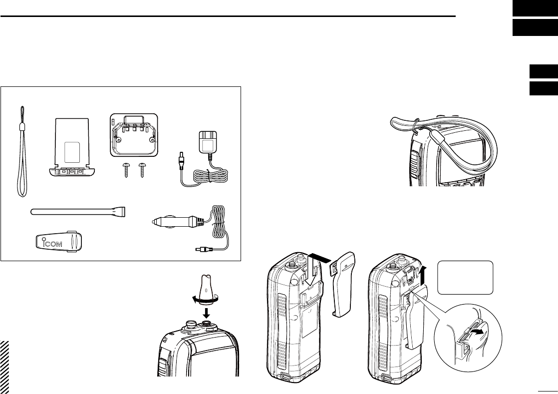
■ Supplied accessories
Battery packHandstrap
Belt clip
Battery charger
(with 2 screws)
Antenna
AC adapter
(Different type is
supplied depending
on the version)
Cigarette lighter cable
■ Attachments
D Flexible antenna
Connect the supplied flexible antenna
to the antenna connector.
CAUTION:
•NEVER carry the transceiver by hold-
ing the antenna.
•Transmittingwithoutanantennamay
damage the transceiver.
D Handstrap
Pass the handstrap through
the loop on the back side of
the transceiver as illustrated
at right. This facilitates carry-
ing.
D Belt clip
Attach/detach the belt clip to the transceiver as illustrated
below.
To attach the belt clip To detach the belt clip
Be careful!
Not to break
your nails.
w
q
3
2SUPPLIED ACCESSORIES AND ATTACHMENTS
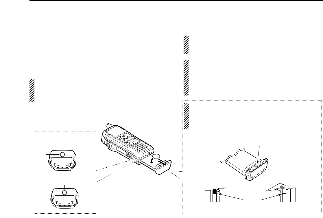
Battery pack D
To remove the battery pack:
Turn the screw counter clockwise one quarter turn, then pull
the battery pack in the direction of the arrow as shown below.
To attach the battery pack:
Insert the battery pack in the transceiver completely, then
turn the screw clockwise one quarter turn.
NEVER remove or insert the battery pack when the trans-
ceiver is wet or soiled. This may result water or dust get-
ting into the transceiver/battery pack and may result in the
transceiver being damaged.
NOTE: When removing or attaching the battery pack, use
a coin or standard screwdriver to loosen or tighten the bot-
tom screw.
CAUTION:
When attaching or removing a battery pack, make sure
the rubber seal is set in the groove of the battery pack
correctly. If the seal is not correctly in the groove, it may
be damaged when attaching the battery pack. If the seal is
damaged, waterproof protection is not guaranteed.
Make sure the rubber seal is properly seated in the
groove and dust or other material does not adhere to it.
Battery pack Battery pack
Rubber seal
Groove
Correct position Incorrect position
NOTE:
When attaching a battery pack, make sure dust or other
material does not adhere to the rubber seal. If dust or other
material is on the seal when attaching a battery pack,
waterproof protection may not be guaranteed.
Screw position
when removing battery
Screw position
when attaching battery
4
3
PANEL DESCRIPTION
1
2
3
4
5
6
7
8
9
10
11
12
13
14
15
16
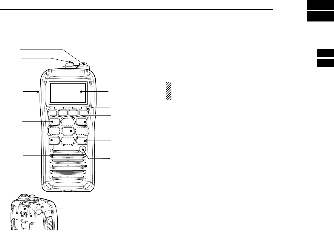
Front, top, side and rear panels ■
Distress button
(p. iii)
Function
display
(pp. 6, 7)
Microphone
t
r
e
y
w
q
!0
i
u
o
Speaker !1
/+%
q ANTENNA CONNECTOR (p. 2)
Connects the supplied antenna.
w
SPEAKER-MICROPHONE CONNECTOR [SP MIC]
(p. 25)
Connects the optional external speaker-microphone.
NOTE: Attach the [SP MIC] cap when the optional
speaker-microphone is not used. Otherwise, water will
get into the transceiver.
e PTT SWITCH [PTT]
Push and hold to transmit; release to receive. (p. 10)
r MENU KEY
Push to enter the Menu mode to select from the following
menus: Adjustment Mode, Inspection Mode, DSC Calls, DSC
Settings, Radio Settings, Configuration, MMSI/GPS Info, MOB,
Waypoint or GPS Status.
Continued on the next page.
5
3PANEL DESCRIPTION
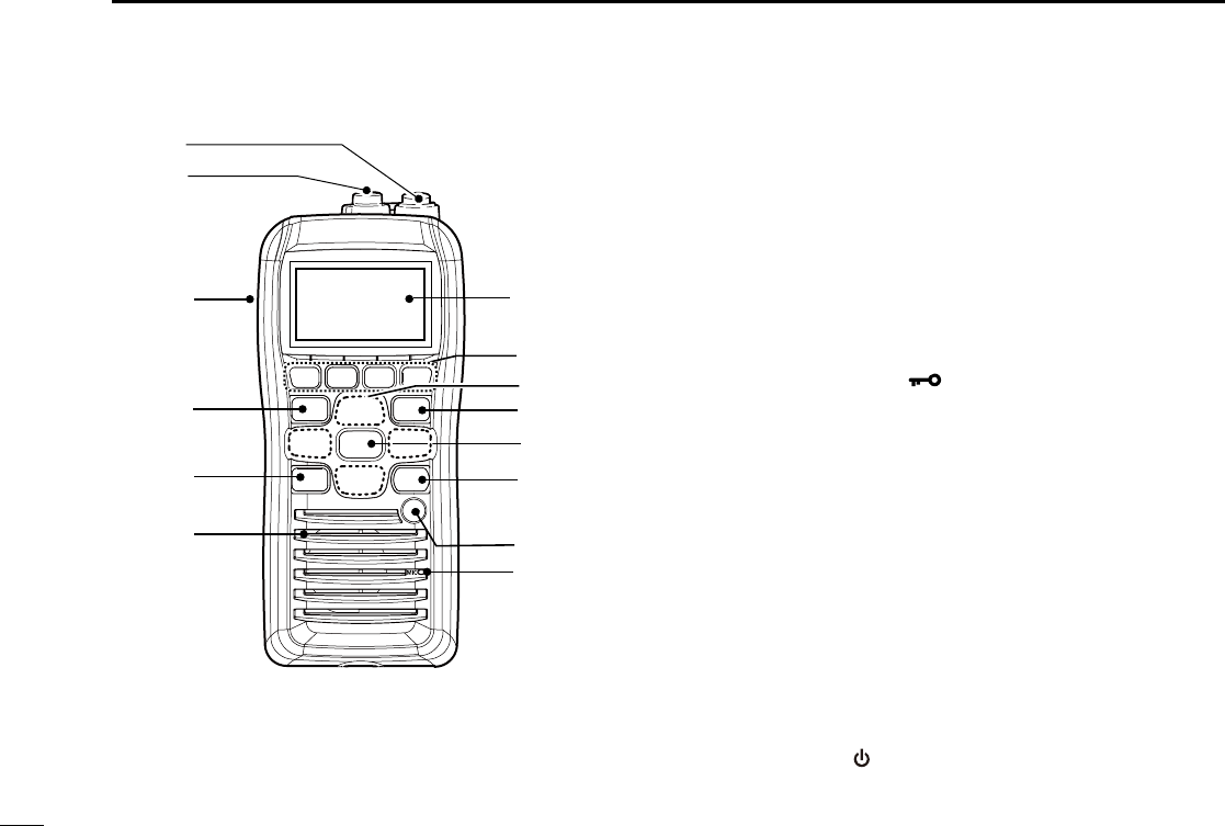
Front, top and rear panels ■
Distress button
(p. iii)
Function
display
(pp. 6, 7)
Microphone
t
r
e
y
w
q
!0
i
u
o
Speaker !1
/+%
t VOLUME/SQUELCH KEY [VOL/SQL]
Push to enter the volume adjustment mode. (pp. 11, ➥
12)
Push again while in the volume adjustment mode to ➥
enter the squelch level adjustment mode.
y SOFT MENU KEYS [1]/[2]/[3]/[4]
Slide menu by pushing [Ω]/[≈] keys, then push either of
the 4 keys to select a menu displayed above on the lower
side of the monitor.
u CHANNEL UP/DOWN [Y]/[Z] AND LEFT/RIGHT [Ω]/[≈]
KEYS
Push ➥ [Y]/[Z] to select an operating channel. (p. )
While in the set mode, selects the setting or value of ➥
an item.
i CLEAR/LOCK KEY [ ]
Push to clear the selected page and return to the previ- ➥
ous screen.
Hold down for 1 second to turn the key lock function ON ➥
or OFF. (p. 13)
o ENTER KEY
Push to select a function, enter the input channel com-
ment, select an item, etc.
!0 CHANNEL 16 KEY [16/C]
Push to select Channel 16. (p. 8) ➥
Hold down for 1 sec. to select the call channel. (p. 8) ➥
When the call channel is selected, hold down for 3 sec. ➥
to enter the call channel programming mode. (p. 11)
While in the set mode, push to return to the normal ➥
condition. (p. 17)
!1 POWER KEY [ ]
Hold down for 1 second to turn the power ON or OFF.
6
3
PANEL DESCRIPTION
1
2
3
4
5
6
7
8
9
10
11
12
13
14
15
16
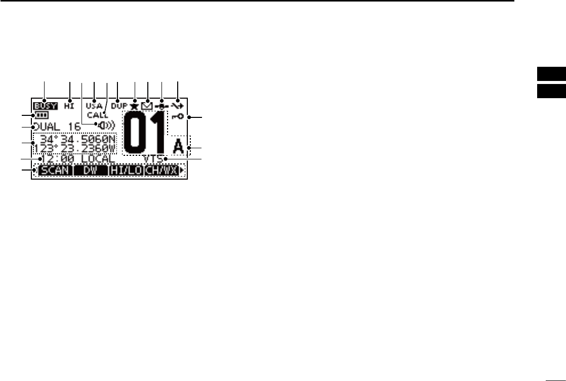
Function display ■
q
!4
wert y uio!0
!1
!2
!3
!5
!6
!7
!8
q BUSY/TRANSMIT INDICATOR (p. 2)
“BUSY” Appears when receiving a signal or when the ➥
squelch opens. (p. 10)
“TX” appears while transmitting. ➥
w POWER ICON (p. 2)
“HI” appears when high power is selected. ➥
“LOW” appears when low power is selected. ➥
e VOLUME LOUD/VOLUME MUTE ICON (p. 12)
Volume loud or volume mute icon appears when the ➥
functions are set.
r CHANNEL GROUP ICON/ WEATHER CHANNEL (p. 9)
Selected channel group icon appears between U.S.A. ➥
“USA,” International “INT,” Canadian “CAN”.
“WX” appears when the weather channel is selected. ➥
The icon blinks while the weather alert function is acti- ➥
vated; blinks when the alert tone is received.
t CALL CHANNEL ICON (p. )
Appears when call channel is selected.
y DUPLEX ICON (p. 2)
Appears when a duplex channel is selected.
u TAG CHANNEL ICON (p. )
The icon appears while a TAG (favorite) channel is se-
lected.
i MAIL ICON (p. )
The icon appears when a message is received.
o GPS ICON (p. )
Stays ON when the GPS receiver is activated and a ➥
valid position data is received.
Blinks when an invalid position data is being received. ➥
!0 AUTO SW ICON (p. )
Blinks when both the Auto Switch function and Auto Tune-
timer are turned OFF.
!1 LOCK ICON (p. )
Appears while the lock function is activated.
!2 CHANNEL NUMBER READOUT (p. 2)
Indicates the selected operating channel number.
!3 CHANNEL NAME INDICATOR (p. 2)
Indicates the channel name of the selected operating
number if programmed.

7
1CHAPTER_CONTINUED
!4 KEY INDICATOR (p. )
Shows the programmed function of the soft keys on the
front panel.
!5 TIME ZONE INDICATOR (p. 2)
Shows the current time data when a GPS receiver is ➥
connected, or the time data is manually programmed.
•WhentheGPScurrenttimedataisinvalid,??mayblinkev-
ery 2 seconds instead of current time data. After 23.5 hours
have passed, “No Time” will appear.
•??mayblink every2 instead of current time data, after 4
hours have passed from the time when the time data was
manually programmed. The manually programmed data is
held for only 23.5 hours, and after that, “No Time” will ap-
pear.
“Local” appears when the offset time data is set. ➥
(p. 44)
“No Time” appears when no GPS receiver is connected ➥
and no time data is manually input.
!6 POSITION INDICATOR (p. 2)
Shows the current position data when a GPS receiv- ➥
er is connected, or the position data is manually pro-
grammed.
•WhentheGPSpositiondataisinvalid,“??”mayblinkevery2
seconds instead of position data. The last position data is held
for only 23.5 hours, and after that, “No Position” will appear.
•“??” may blink every 2 seconds instead of position data, af-
ter 4 hours have passed from the time when the position data
is manually programmed. The manually programmed position
data is held for only 23.5 hours, and after that, “No Position” will
appear.
“No Position” appears when no GPS receiver is con- ➥
nected and no position data is input manually.
!7 SCAN INDICATOR (p. 2)
“SCAN 16” appears during a Priority scan; “SCAN” ap- ➥
pears during a Normal scan. (p. 17)
“DUAL 16” appears during Dualwatch; “TRI 16” appears ➥
during Tri-watch. (p. 18)
!8 BATTERY INDICATOR
Indicates the battery's remaining power.
Indication
Full Middle Charging
required No battery
Battery level
blinks when the battery is over charged.
8
4
PREPARATION
1
2
3
4
5
6
7
8
9
10
11
12
13
14
15
16
MMSI code programming ■
The 9 digit MMSI (Maritime Mobile Service Identity: DSC self
ID) code can be programmed at power ON.
NOTE:
•This initial code programming can be performed only the
first time to turn the power ON.
•Theprogrammingcanonlybedoneonce.
•After the programming is completed, it can be re-pro-
grammed only by your dealer or distributor.
First, push q [ ] turn ON the power.
•Theopeningdisplayappears.
•“MMSI” display appears and warning alarm sounds for 2
seconds.
“Push [ wENT] to Register Your MMSI” appears.
•Donotpush[CLEAR] while this screen is displayed.
Push e[Y]/[Z]/[Ω]/[≈] to select and input with [ENTER].
r Select “FINISH” and push [ENTER] to register.
t When “MMSI CONFIRMATION” screen appears, input the
previously registered 9 digited code to confirm the regis-
tration. Then, push [ENTER] to register.
•Automatically enters the functional mode if the registration is
valid.
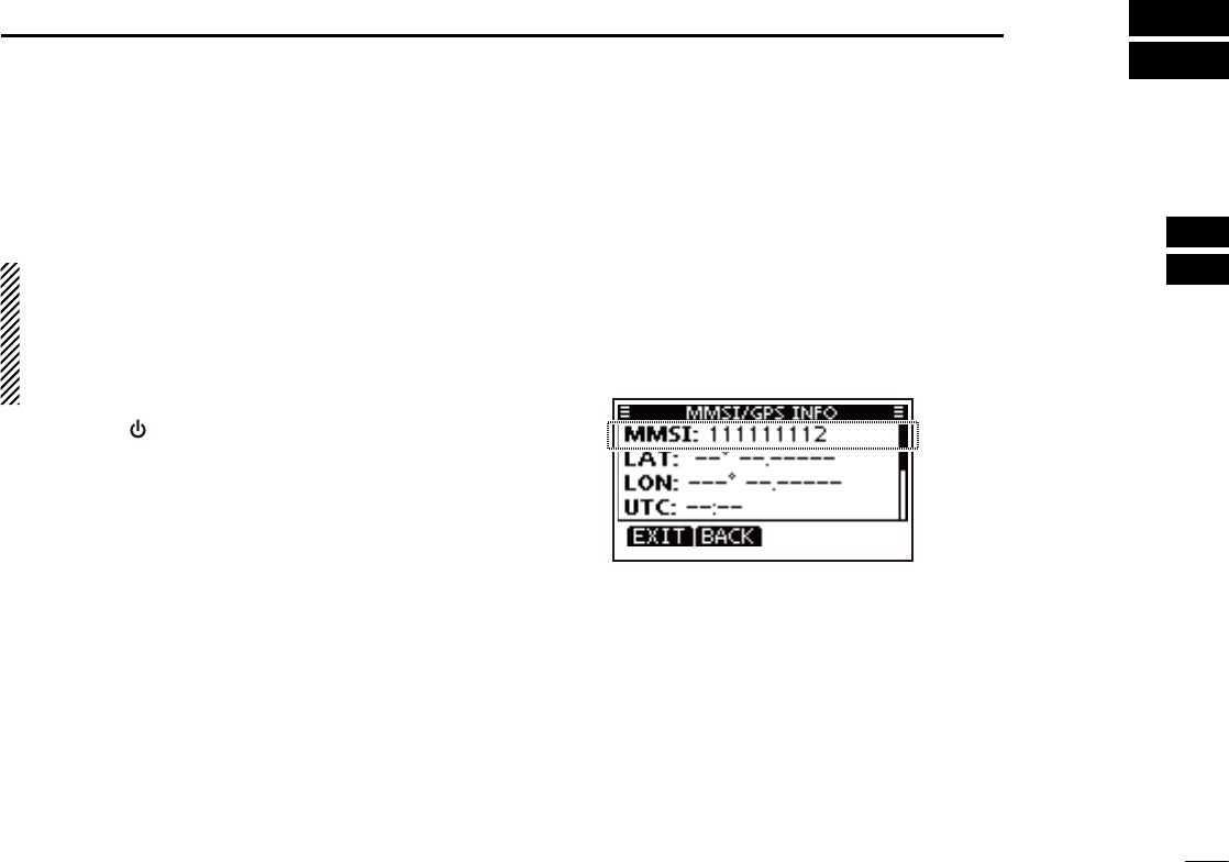
MMSI code check D
The 9 digit MMSI code can be checked.
Push q[MENU].
Push w[Y]/[Z] several times to select “MMSI/GPS Info”,
then push [ENTER] to enter.
Select “ eEXIT” to return to the main menu screen or “BACK”
to return to the previous screen.
9
5BASIC OPERATION
Channel selection ■
IMPORTANT: Prior to using the transceiver for the first
time, the battery pack must be fully charged for optimum
life and operation. To avoid damage to the transceiver,
turn the power OFF while charging.
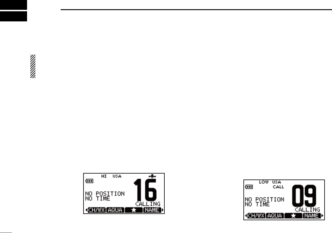
Channel 16 D
Channel 16 is the distress and safety channel. It is used for
establishing initial contact with a station and for emergency
communications. Channel 16 is monitored during both Du-
al-watch and Tri-watch. While in the standby condition, you
must monitor Channel 16.
Push q[16/C] to select Channel 16.
•“CALLING”appears.
Select w[CH/WX] to return to the selected channel before
Channel 16, or push [Y]/[Z] to select an operating chan-
nel.
Push [16/C] key
Call channel D
Each regular channel group has separate leisure-use call
channels. The call channel is monitored during Tri-watch.
The call channels can be programmed (p. 11) and are used
to store your most often used channel in each channel group
for quick recall.
Hold down q[16/C] for 1 second to select Call channel.
•“CALLING”andthecallchannelnumberappear.
•Callchannelcanbere-programmed.Seethe“Callchannelpro-
gramming” on page 10 for details.
Select w“CH/WX” to return to the selected channel before
the call channel, or push [Y]/[Z] to select the operating
channel.
Hold down [16/C] key
for 1 second
10
5
BASIC OPERATION
1
2
3
4
5
6
7
8
9
10
11
12
13
14
15
16
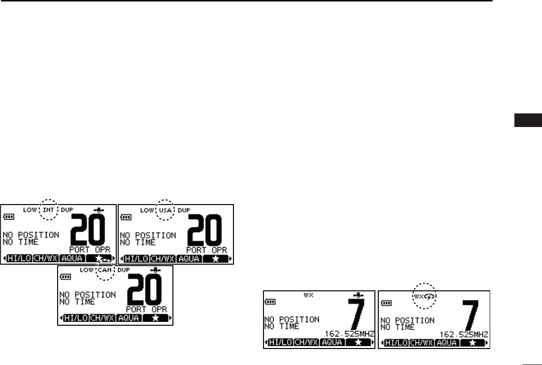
U.S.A., International and Canadian channels D
The transceiver is pre-programmed with 59 U.S.A., 59 Inter-
national and 63 Canadian channels. These channel groups
may be specified for the operating area.
Push [ qMENU].
Push w[Y]/[Z] to select “Radio Settings”.
•U.S.A.,InternationalandCanadianchannelgroupscanbese-
lected in sequence.
Push e[Y]/[Z] to select “CHAN Group”.
r Select between “USA”, “INT” and “CAN”.
t Select “EXIT” while the desired channel group is selected
to return to the home screen.
•“DUP” appears for duplex channels.
Weather channels D
The IC-M92D has 10 pre-programmed weather channels.
These are used for monitoring broadcasts from NOAA (Na-
tional Oceanographic and Atmospheric Administration.)
The transceiver can automatically detect a weather alert tone
on the selected weather channel while receiving on another
channel, during standby on a regular channel or while scan-
ning. (p. 44)
To Select a Weather channel:
Select “CH/WX” to select a weather channel.
•“WX”appearswhenaweatherchannelisselected.
•Weather channel alert icon appears when the alert function is
turned ON.
To set the Weather Alert:
Push q[MENU].
Push w[Y]/[Z] to select “Radio Settings”.
Push e[Y]/[Z] to select “WX Alert”.
r Select “ON” to set the Weather Alert. .
t Select “EXIT” while “ON” is selected to return to the home
screen.
•WX Alert icon appears.

11
5BASIC OPERATION
Receiving and transmitting ■
CAUTION: Transmitting without an antenna may damage
the transceiver.
Hold down q[] for 1 second to turn power ON.
Set the volume and squelch levels with w[VOL/SQL].
Set the volume by pushing ➥[Y]/[Z] to adjust the vol-
ume.
Set the squelch level by pushing ➥[VOL/SQL] while the
volume adjustment mode is selected.
•While in the squelch adjustment mode, pushing [Y] will
make the noise disappear.
Push e[Y]/[Z] to select the desired channel.
•Further adjustment of the audio may be necessary at this
point.
r Select “HI/LO” to select the output power if necessary.
•“HI”appearswhenhighpowerisselected;“LOW”whenhigh
power is selected.
•Choose low power for short range communications, choose
high power for longer distance communications.
•Somechannelsareforlowpoweronly.
t Hold down [PTT] to transmit, then speak into the micro-
phone.
•Channel70cannotbeusedfortransmission.
t Release [PTT] to receive.
IMPORTANT: To maximize the readability of your trans-
mitted signal, pause a few seconds after pushing [PTT],
hold the microphone 5 to 10 cm (2 to 4 inches) from your
mouth and speak into the microphone at a normal voice
level.
NOTE: The transceiver has a power save function to con-
serve the battery power. The power save function activates
automatically when no signal is received for 5 seconds.
For U.S.A. version: To prevent accidental prolonged
transmission, etc., the transceiver has a time-out timer
function. This timer cuts a transmission OFF after 5 min-
utes of continuous transmission.

12
5
BASIC OPERATION
1
2
3
4
5
6
7
8
9
10
11
12
13
14
15
16
Call channel programming ■
Call channel is used to access the Call Channel 9 (default),
however, you can program the call channel with your most
often-used channels in each channel group for quick recall.
Select the qdesired channel group (U.S.A, International or
Canada) to be programmed. (p. )
Hold down w[16/C] for 1 second to select the call channel of
the selected channel group.
•“CALLING” and call channel number appear.
Hold down e[16/C] again until long beep stops with two
short beeps. The channel programming mode screen is
displayed.
r Push [Y]/[Z] to select the desired channel.
t Push [ENTER] to program the selected channel as the call
channel.
•Thedisplayautomaticallyreturnstothemainmenuscreen.
Adjusting the volume level ■
The volume level can be adjusted with [VOL/SQL] and [Y]/
[Z] keys.
Push q[VOL/SQL] once to enter the volume adjustment
mode, then adjust the volume level with [Y]/[Z].
• The transceiver has 20 volume levels and OFF.
•Withnokeyoperationisperformedfor5seconds,itreturnsto
the main menu.
Push w[VOL/SQL] twice to exit the volume adjustment
mode.
Adjusting the squelch level ■
The squelch level can be adjusted with [VOL/SQL] and [Y]/
[Z] keys.
In order to receive signals properly, as well as for the scan
to function effectively, the squelch must be adjusted to its
proper level.
Push q[VOL/SQL] twice to enter the squelch adjustment
mode, then adjust the squelch level with [Y]/[Z].
•Thetransceiverhas11squelchlevels:OPiscompletelyopen;
10 is tight squelch; 1 is loose squelch.
•Withnokeyoperation isperformedfor5seconds,thetrans-
ceiver returns to the main screen.
Push w[VOL/SQL] again to exit the adjustment mode and
return to the main menu screen.
13
5BASIC OPERATION
Volume loud function ■
The volume loud function can be activated temporarily by
pushing [VOL/SQL] and [Y].
The function does not work when the volume level is al-
ready set to the maximum 20.
Hold down q[VOL/SQL] first, and then while holding it down,
push [Y] to activate the volume loud function.
•Thevolumelevelissettothemaximumlevel(level20).
•Thevolumeiconappears.
Push w[ENTER] to turn the volume function OFF.
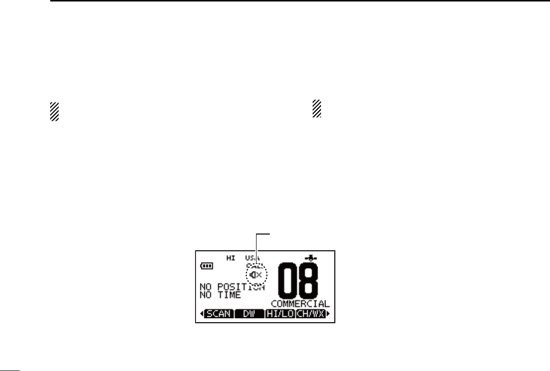
Volume mute function ■
The volume mute function can be activated temporarily by
pushing [VOL/SQL] and [Z].
The function does not work when the volume level is al-
ready OFF.
Hold down q[VOL/SQL] first, and then while holding it down,
push [Z] to activate the volume loud function.
•Thevolumelevelissettotheminimumlevel(OFF).
•Volumemuteiconappears.
Push w[ENTER] to turn the volume mute function OFF.
The volume mute or volume loud icon appears.

14
5
BASIC OPERATION
1
2
3
4
5
6
7
8
9
10
11
12
13
14
15
16
Lock function ■
This function electronically locks all keys (except for [PTT]
and [ ]) to prevent accidental channel changes and function
access.
Push ➥[CLEAR/ ] for 1 second to turn the lock function
ON and OFF.
Appears while the lock
function is activated.
Monitor function ■
This function lights the function display and keys, and it is
convenient for night-time operation. The automatic backlight-
ing can be set in the set mode. (p. 19)
Push any key except for ➥[PTT] to turn the backlight ON.
•Thebacklightis automaticallyturnedOFF after 5secondsof
inactivity.
AquaQuake water draining ■
function
The AquaQuake water draining function clears water away
from the speaker grill. Without this function, water may muffle
the sound coming from the speaker. The transceiver emits a
vibrating beep when this function is activated.
Select ➥“AQUA” and hold down the soft key.
•Abeepsoundsfor10secondstodrainwater,regardlessofthe
volume level setting.
•Thetransceiver neveracceptskeyoperationwhiletheAqua-
Quake function is activated.
•TheAquaQuakefunctioncannotbeactivatedwhenanoptional
speaker-microphone is connected.
15
5BASIC OPERATION
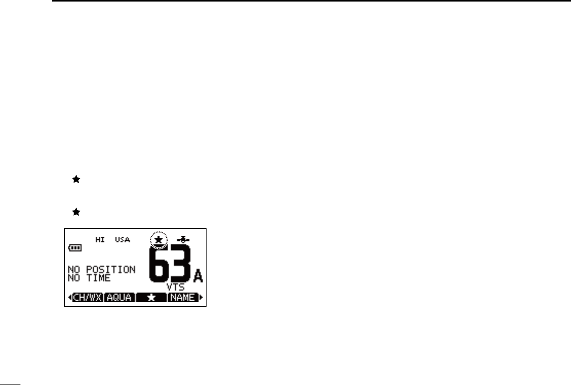
Setting TAG channels ■
For more efficient scanning, add the desired channels as
TAG channels or clear TAG for unwanted channels. Chan-
nels that are not tagged will be skipped during scanning. TAG
channels can be assigned to each channel group (U.S.A.,
International and Canada) independently.
Select q“CH/WX” to select the desired channel group.
While the desired channel is selected on the display, se- w
lect the TAG icon on the soft keys.
•“” appears on the display.
To cancel a TAG channel setting, select the desired TAG e
channel, then select the TAG icon on the soft keys.
•“” disappears.
To Clear (or set) all tagged channels:
Hold down to select TAG for 3 seconds on the soft keys until a short
beep sounds. This clears all tags or tag all channels.
Channel names ■
Each channel can be labeled with alphanumeric names of up
to 10 characters for easy channel recognition.
The programmed names will be indicated at the chan- ➥
nel name indicator of the function display.
Capital letters, numbers, 26 types of symbols and ➥
space can be used.
Select the desired channel. q
•Canceldualwatch,Tri-watchorScaninadvance.
While the desired channel is displayed, select w“NAME” to
enter the channel name edtting mode screen.
Select the desired character by pushing e[Y]/[Z]/[Ω]/[≈]
keys, and then input with [ENTER].
•Whileinthechannelnameedittingmode,pushtheveryright
key of the soft keys to change between alphabets, numers and
symbols.
•Select “DELETE” to delete the selected character and select
“SPACE” to insert a space.
r Select “FINISH” to program the name.
•Automaticallyreturnstothemainmode.
•Theprogrammednameappearsonthedsiplay.

16
5
BASIC OPERATION
1
2
3
4
5
6
7
8
9
10
11
12
13
14
15
16
Backlight setting ■
This function lights the function display and keys, and it is
convenient for night-time operation.
Select q“BKLT” to enter the backlight adjusting mode.
Push w[Y] or [Z] to adjust the brightness level between
1(minimum) to 7 (maximum) or OFF.
•Thedefaultsettingis3.
•Thedisplayreturnsautomaticallytothemainmanuafter5sec-
onds without no key operation is been performed.
17
6SCAN OPERATION
Scan types ■
Scanning is an efficient way to locate signals quickly over a
wide frequency range. The transceiver has priority scan and
normal scan.
In addition, the weather alert and auto scan functions are
available for standby convenience. These functions can be
activated simultaneously, depending on the setting in the set
mode.
WX*
CH 01
CH 16
CH 02
CH 05 CH 04
CH 03
Previously selected weather channel.
(when the weather alert function is activated)
*
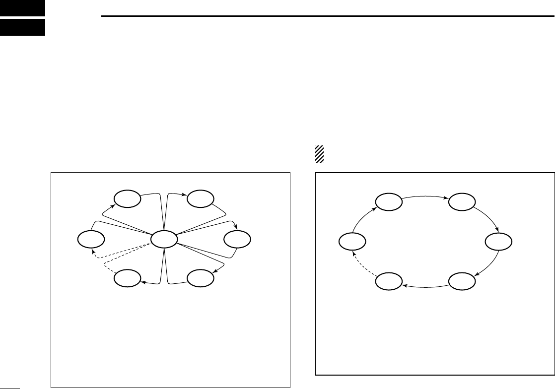
PRIORITY SCAN
Priority scan searches through all TAG channels in
sequence while monitoring Channel 16. When a signal is
detected on Channel 16, scan pauses until the signal
disappears; when a signal is detected on a channel other
than Channel 16, scan becomes Dualwatch until the
signal disappears.
Set the TAG channels (scanned channels) before scanning.
Clear the TAG for unwanted channels which inconveniently
stop scanning, such as those for digital communications. (p.
15)
Choose the desired scan type from “Priority” or “Normal” in
the set mode.
CH 01 CH 02
WX*
CH 05 CH 04
CH 03
Previously selected weather channel.
(when the weather alert function is activated)
*
NORMAL SCAN
Normal scan, like priority scan, searches through all TAG
channels in sequence. However, unlike priority scan,
Channel 16 is not checked unless Channel 16 is set as a
TAG channel.

18
6
SCAN OPERATION
1
2
3
4
5
6
7
8
9
10
11
12
13
14
15
16
Starting a scan ■
Set the scan type (Priority or Normal scan), WX Alert function
and Scan Timer function in advance, using the se mode.
To select a scan type:
Select the scan type between Normal scan and Priority scan.
Push q [MENU].
Push w[Y] or [Z] to select “Radio Settings”, then push [EN-
TER].
Select “ eScan Type”, then push [ENTER].
r Select “Normal Scan” or “Priority Scan” and push [ENTER]
to program.
t Select “BACK” to return to the previous page, or simply
select “EXIT” to return to the main menu screen.
•“SCAN” appears if“Normal Scan” is selected, and “SCAN 16”
apppears if “Priority Scan” is selected as show below.
To scan:
Select “SCAN” and push on the soft key to start or stop scan-
ning.
•Pushing[PTT] also stops the scan.
•Whenasignalisreceived,scanpausesuntilthesignaldisappears
or resumes after pausing for 5 seconds according to the Scan Timer
setting.
•While scanning, push [Y] or [Z] to check which channels have
been set as TAG channels or to change the scanning direction.
19
7DUALWATCH/TRI-WATCH
Description ■
Dualwatch monitors Channel 16 while you are receiving on
another channel; Tri-watch monitors Channel 16 and the call
channel while receiving another channel. Dualwatch/Triwatch
is convenient for monitoring Channel 16 when you are oper-
ating on another channel.
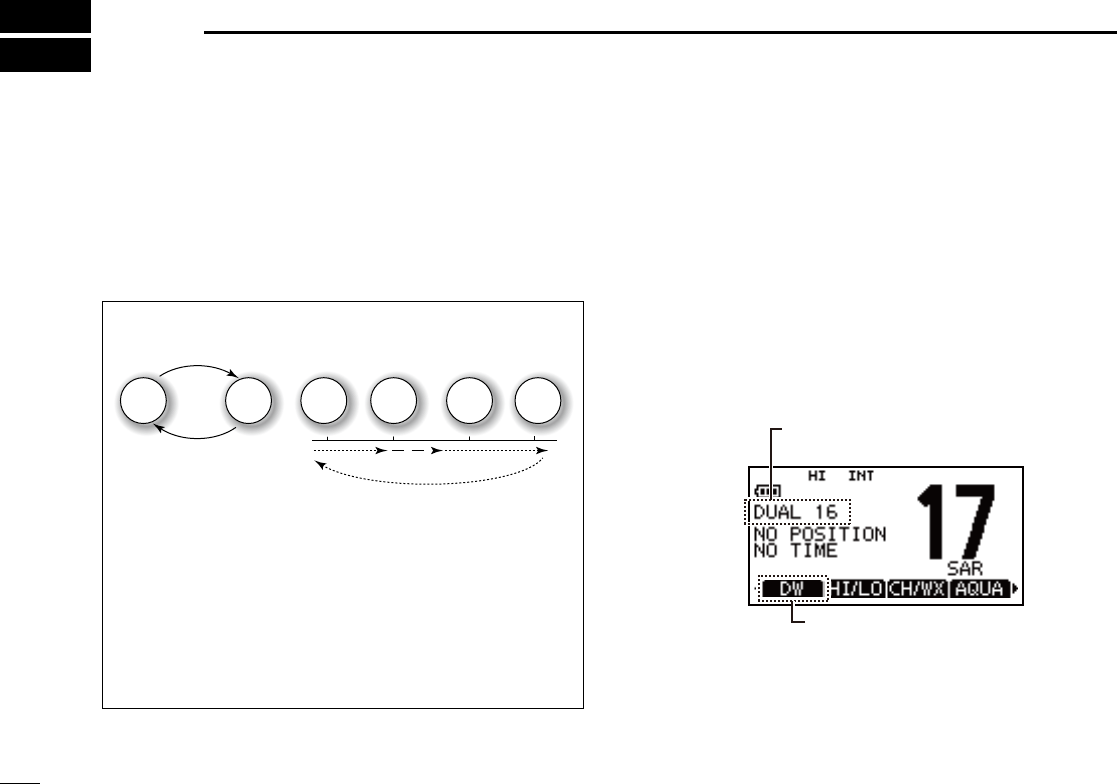
DUALWATCH/TRI-WATCH SIMULATION
DualwatchTri-watch
Call
channel
Ch 88
Ch 16 Ch 88 Ch 16 Ch 88 Ch 9
•IfasignalisreceivedonChannel16,Dualwatch/Tri-watch
pauses on Channel 16 until the signal disappears.
•IfasignalisreceivedonthecallchannelduringTri-watch,
Tri-watch becomes Dualwatch until the signal disap-
pears.
•To transmit on the selected channel during Dualwatch/
Tri-watch, hold down [PTT].
Operation ■
Push q [MENU].
Push w[Y] or [Z] to select “Radio Settings”, then push [EN-
TER].
Select “ eDual/Tri-Watch”, then push [ENTER].
r Select “Dualwatch” or “Tri-watch” and push [ENTER] to
program.
t Select “BACK” to return to the previous page, or simply
select “EXIT” to return to the main menu screen.
•“DUAL16”appearsif“Dualwatch” is selected, and “TRI 16” app-
pears if “Tri-watch” is selected as shown below.
DUAL 16 or TRI 16 appears,
depending on the setting.
Select to start Dualwatch
or Tr i-watch.
20
8
DSC OPERATION
1
2
3
4
5
6
7
8
9
10
11
12
13
14
15
16
DSC address ID ■
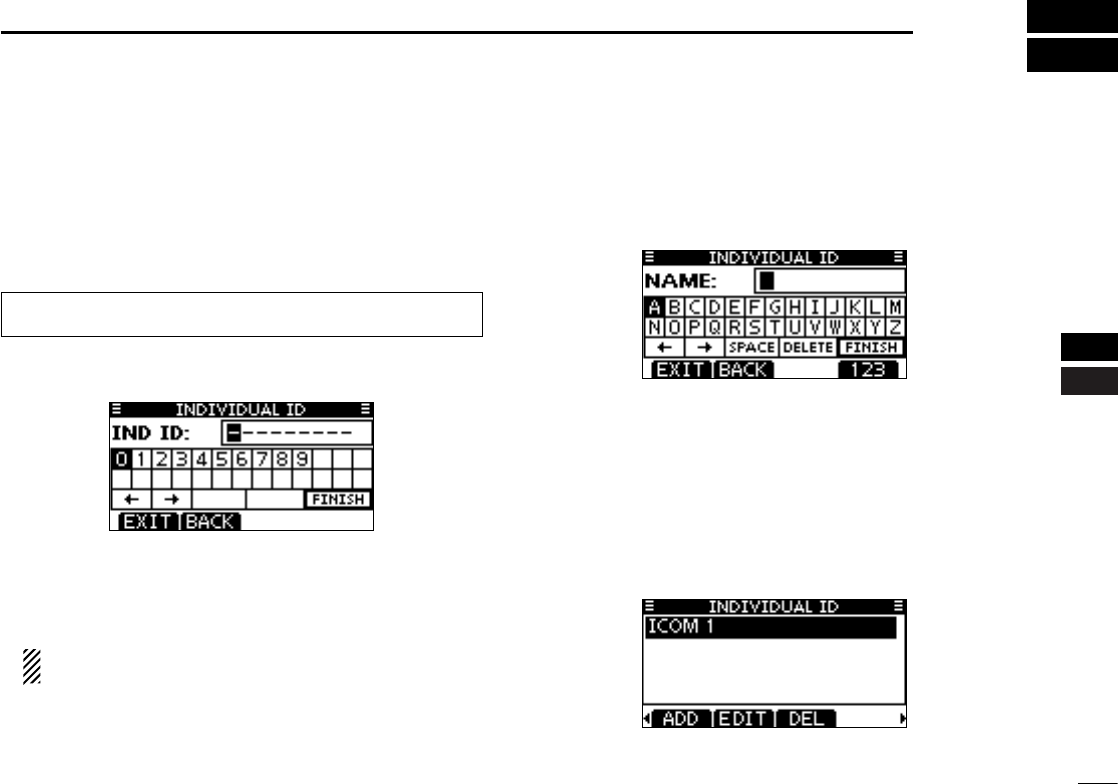
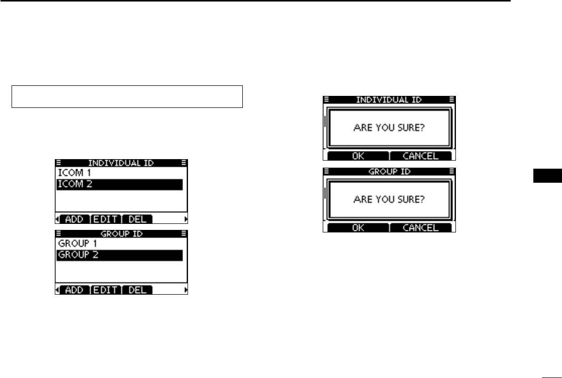
Programming Individual ID D
A total of 100 DSC address IDs can be programmed and as-
signed a name of up to 10 characters.
Enter “INDIVIDUAL ID” in the DSC SETTINGS menu. q
Push [ADD]. w
•The“INDIVIDUALID”programscreenisdisplayed.
Enter a desired individual ID in the following instruction: e
•Selectadesirednumberusing[Y]/[Z]/[Ω]/[≈].
•Push[ENT]tosetit.
•Tomovethecursor,selecteitherarrow,“←” or “→,” then push
[ENT].
The first digit is specified as ‘0’ for a Group ID.
The first two digits are ‘0’ for any Coast station ID.
Repeat step r e to enter all 9 digits.
After entering the 9 digit code, push [ENT] to set it. t
•IDnameprogrammingscreenisdisplayed.
Enter a desired 10 digit ID name in the following instruction: y
•Selectadesiredcharacterusing[Y]/[Z]/[Ω]/[≈].
•Push[ENT]tosetit.
•Tomovethecursor,selecteitherarrow,“←” or “→,” then push
[ENT].
•Push[123]then[!$?]then[ABC]toselectacharactergroup.
After entering the ID name, select “FINISH” by pushing u
[Y]/[Z]/[Ω]/[≈], then push [ENT] to program it.
The “INDIVIDUAL ID” list screen is displayed. i
•Push[MENU]toexittheMENUscreen.
MENU ➪ DSC Settings ➪
Individual ID
(Push [MENU])
(Push
[Y]/[Z]
, then push [ENT].)
21
8DSC OPERATION
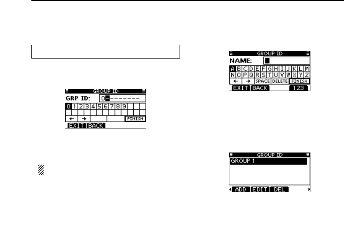
Programming Group ID D
Enter “GROUP ID” in the DSC SETTINGS menu. q
•WhennogroupIDisprogrammed,“NoID”isdisplayed.Inthis
case, push [MENU] to exit the MENU screen.
Push [ADD]. w
•The“GROUPID”programscreenisdisplayed.
Enter a desired group ID in the following instruction: e
•Selectadesirednumberusing[Y]/[Z]/[Ω]/[≈].
•Push[ENT]tosetit.
•Tomovethecursor,selecteitherarrow,“←” or “→,” then push
[ENT].
The first digit is fixed as ‘0’ for a Group ID.
The first two digits are ‘0’ for any Coast station ID.
Repeat step r e to input the specific 9 digits group code.
After entering the 9 digit code, push [ENT] to set it. t
•GroupIDnameprogrammingscreenisdisplayed.
Enter a desired 10 digit ID name in the following instruction: y
•Selectadesiredcharacterusing[Y]/[Z]/[Ω]/[≈].
•Push[ENT]tosetit.
•Tomovethecursor,selecteitherarrow,“←” or “→,” then push
[ENT].
•Push[123],[!$?]or[ABC]toselectacharactergroup.
After entering the ID name, select “FINISH” pushing [ uY]/
[Z]/[Ω]/[≈], then push [ENT] to program it.
•The“GROUPID”listscreenisdisplayed.
Push [MENU] to exit the MENU screen. i
MENU ➪ DSC Settings ➪
Group ID
(Push [MENU])
(Push
[Y]/[Z]
, then push [ENT].)
22
8
DSC OPERATION
1
2
3
4
5
6
7
8
9
10
11
12
13
14
15
16
Deleting Individual/Group ID D
Enter “INDIVIDUAL ID” or “GROUP ID” in the DSC SET- q
TINGS menu.
•WhennoaddressIDisprogrammed,“NoID”isdisplayed.In
this case, push [MENU] to exit the MENU screen.
Select a desired ID name (or ID, if no name is programmed) w
with Dial or [Y]/[Z] to be deleted, then push [DEL].
Push [OK] to delete the ID, and return to the “INDIVIDUAL e
ID” or “GROUP ID” list screen.
•Push[CANCEL]tocancelit.
Push [MENU] to exit the MENU screen. r
MENU ➪ DSC Settings ➪
Individual ID
/
Group ID
(Push [MENU])
(Rotate Dial, then push [ENT].)
23
8DSC OPERATION
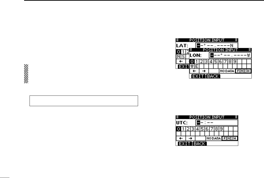
A Distress call should include the ship’s position and time
data. If no GPS is connected, your position and UTC (Univer-
sal Time Coordinated) time should be manually input. They
are automatically included when a GPS receiver compatible
with the NMEA0183 ver. 2.0 or 3.01 format is connected.
•ManualprogrammingisdisabledwhenaGPSreceiveris
connected.
•Manuallyprogrammedpositionandtimedatawillbeheld
for only 23.5 hours.
Enter “POSITION INPUT” in the DSC SETTINGS menu. q
Edit your latitude and longitude position data using Dial, or w
[Y]/[Z]/[Ω]/[≈].
•SelectadesirednumberusingDial,or[Y]/[Z]/[Ω]/[≈].
•Push[ENT]orDialtosetit.
•Tomovethecursor,selecteitherarrow,“←” or “→,” then push
[ENT].
•SelectN:NorthlatitudeorS:Southlatitudewhenthecursoris
on the ‘N’ or ‘S’ position.
•SelectW:WestlongitudeorE:Eastlongitudewhenthecursor
is on the ‘W’ or ‘E’ position.
After entering the position data, push [ENT] to program it. e
The UTC time programming screen is displayed, enter the r
UTC time in the following way:
•Selectadesirednumberusing[Y]/[Z]/[Ω]/[≈].
•Push[ENT]tosetit.
•Tomovethecursor,selecteitherarrow,“←” or “→,” then push
[ENT].
Push [ENT] to program your position and time data. t
•Returntothe“DSCSETTING”screen.
Position and time programming ■
MENU ➪ DSC Settings ➪ Position Input
(Push [MENU])
(Push
[Y]/[Z]
, then push [ENT].)
24
1
DSC OPERATION
1
2
3
4
5
6
7
8
9
10
11
12
13
14
15
16
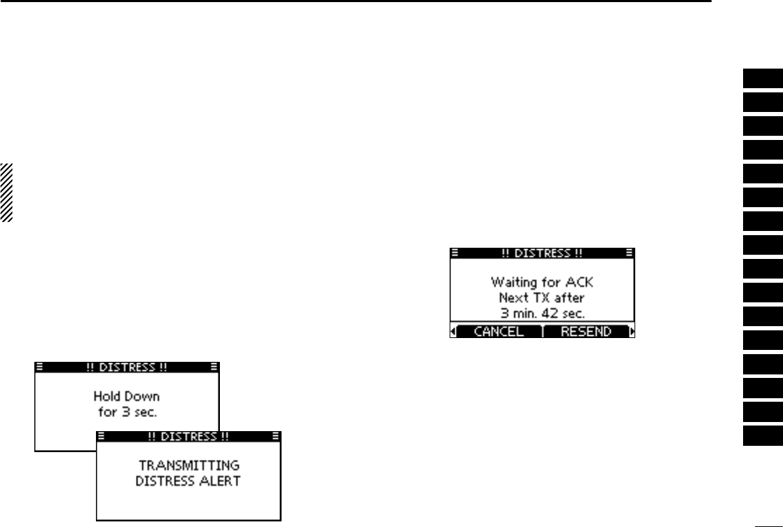
Distress call ■
A Distress call should be transmitted if, in the opinion of the
Master, the ship or a person is in distress and requires im-
mediate assistance.
NEVER MAKE A DISTRESS CALL IF YOUR SHIP OR A
PERSON IS NOT IN AN EMERGENCY. A DISTRESS
CALL SHOULD BE MADE ONLY WHEN IMMEDIATE
HELP IS NEEDED.
Simple call D
Confirm no Distress call is being received. q
While lifting up the key cover, hold down [DISTRESS] for 3 w
seconds to transmit the Distress call.
•While holding down [DISTRESS], count down beeps sound
and both the key and display backlighting blink.
•DSCchannel(Channel 70) isautomatically selected andthe
Distress call is transmitted.
After transmitting the call, the transceiver waits for an ac- e
knowledgment call.
•TheDistresscallisautomaticallytransmittedevery3.5to4.5
minutes, until an acknowledgement is received (‘Call repeat’
mode), or DSC Cancel call is made (p. 26).
•Push[RESEND]tomanuallytransmittheDistressrepeatcall.
•Push[Ω]/[≈] then push [INFO] to display the transmitted Dis-
tress call information.
•Push [Ω]/[≈] then push [PAUSE] to pause the ‘Call repeat’
mode, push [RESUME] to resume it.
After receiving the acknowledgment, push [ALARM OFF] r
then reply using the microphone.
A distress alert contains (default):
•Natureofdistress:Undesignateddistress
•Positiondata :The latest GPS or manual input position
data is held for 23.5 hours, or until the pow-
er is turned OFF.
25
8DSC OPERATION
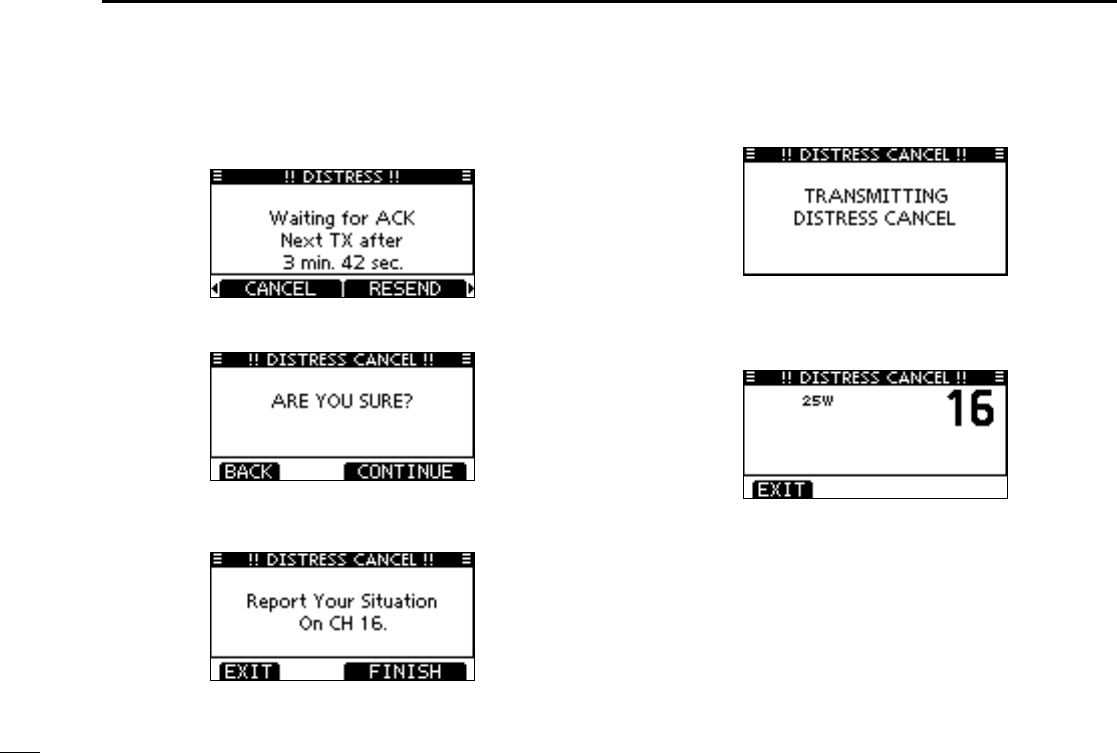
Distress cancel call D
While waiting for an acknowledgment call, push [CAN- q
CEL].
Push [CONTINUE]. w
•Push[BACK]toreturntowaitingforanacknowledgementcall.
Push [FINISH]. e
•Push[EXIT]toreturntowaitingforanacknowledgementcall.
The Distress cancel call is transmitted. r
Channel 16 is automatically selected. t
•Reportyoursituationusingthemicrophone.
•Afterthereport,push[EXIT]toreturntothenormaloperating
mode.
26
8
DSC OPERATION
1
2
3
4
5
6
7
8
9
10
11
12
13
14
15
16
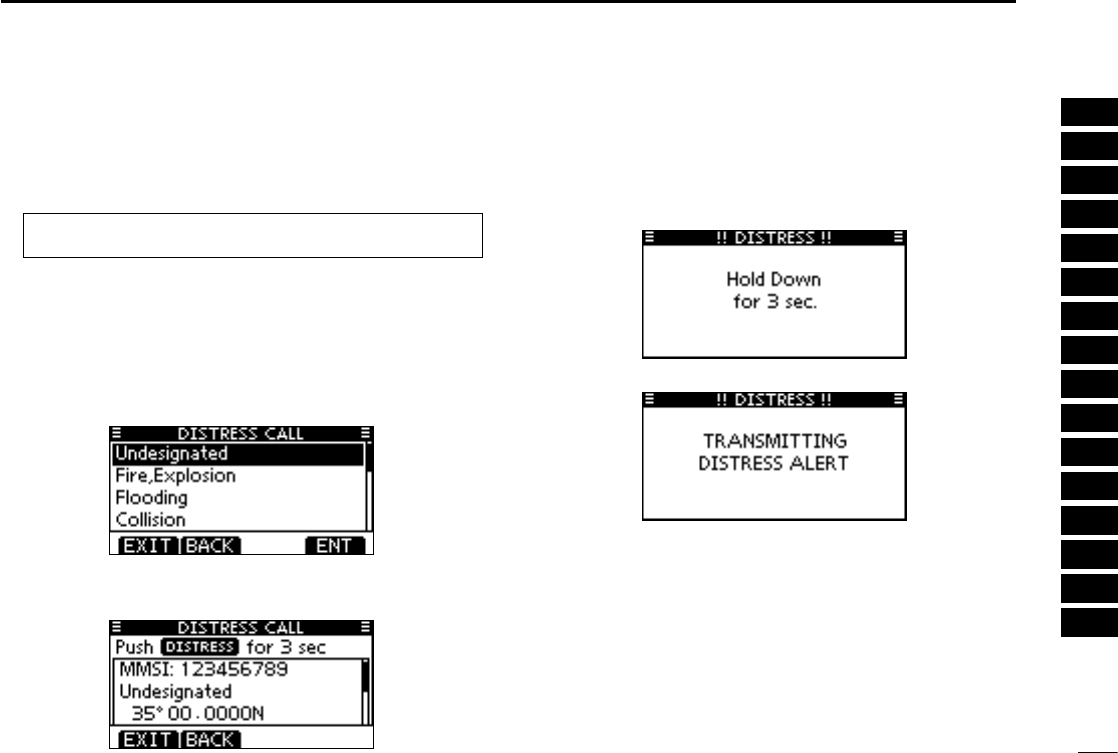
Regular call D
The nature of the Distress call should be included in the Dis-
tress call.
Enter “DISTRESS CALL” in the DSC CALLS menu. q
Select the nature of the distress using Dial or [ wY]/[Z], then
push Dial or [ENT].
•‘Undesignated,’‘Fire,Explosion,’‘Flooding,’‘Collision,’‘Ground-
ing,’ ‘Capsizing,’ ‘Sinking,’ ‘Adrift,’ ‘Abandoning ship,’ ‘Piracy’ or
‘Man Overboard’ is selectable.
•Thenatureofthedistressisstoredfor10minutesafteraselec-
tion is made.
The Distress call confirmation screen is displayed. e
•RotateDialorpush[Y]/[Z] to see the hidden lines.
Hold down [DISTRESS] for 3 seconds to transmit the Dis- r
tress call.
•While holding down [DISTRESS], count down beeps sound
and both the key and display backlight blink.
•Theselectednatureofthedistressisstoredfor10minutes.
MENU ➪ DSC Calls ➪ Distress Call
(Push [MENU])
(Push
[Y]/[Z]
, then push [ENT].)
27
8DSC OPERATION
Transmitting DSC calls ■
To ensure correct operation of the DSC function, make
sure you correctly set the CH70 SQL LEVEL. (p. 64)
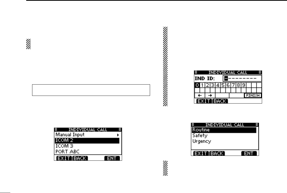
Transmitting an individual call D
The Individual call function allows you to transmit a DSC sig-
nal to only a specific station.
Enter “INDIVIDUAL CALL” in the DSC CALLS menu. q
Select the desired preprogrammed individual address, or w
“Manual Input,” using [Y]/[Z], then push [ENT].
•TheIDcodefortheIndividualcallcanbesetrst.(p.19)
•When“ManualInput”isselected,setadesired9digitMMSIID
code for the individual you wish to call.
About Manual Inputting:
Enter a desired individual ID in the following way:
•Selectadesirednumberusing[Y]/[Z]/[Ω]/[≈].
•Push[ENT]tosetit.
•Tomovethecursor,selecteitherarrow,“←” or “→,” then push
[ENT].
•Therstdigitisspeciedas‘0’foraGroupID.
•Thersttwodigitsare‘0’foranycoaststationID.
Select Routine, Safety or Urgency as the desired call type e
using [Y]/[Z], then push [ENT].
NOTE: When a coast station is selected in step w, the
voice channel is automatically specified by the coast sta-
tion. Therefore, skip step r and go directly to step t.
☞ Continued on the next page.
MENU ➪ DSC Calls ➪ Individual Call
(Push [MENU])
(Push
[Y]/[Z]
, then push [ENT].)
28
8
DSC OPERATION
1
2
3
4
5
6
7
8
9
10
11
12
13
14
15
16
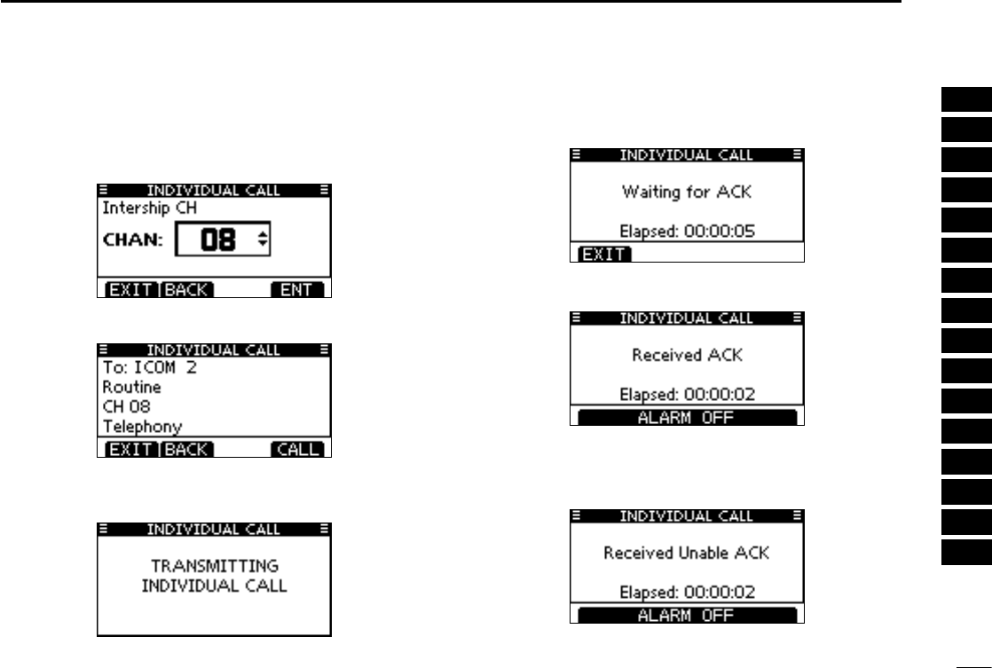
Transmitting an Individual call (continued) D
Select a desired intership channel using [ rY](CH)/[Z](CH),
then push [ENT].
•Intershipchannelsarealreadypresetintothetransceiverinthe
recommended order.
A confirmation screen appears. t
•Conrmthecallcontents.
Push [CALL] to transmit the Individual call. y
•IfChannel70isbusy,thetransceiverstandsbyuntilthechan-
nel becomes clear.
Standby on Channel 70 until an acknowledgement is re- u
ceived.
When the acknowledgement ‘Able to comply’ is received, i
beeps sound and the screen below is displayed.
Or, when the acknowledgement ‘Unable to comply’ is re-
ceived, beeps sound and the screen below is displayed.
•Push[ALARMOFF]tostop thebeepsand thenreturntothe
operating channel (before you entered the MENU screen).
29
8DSC OPERATION
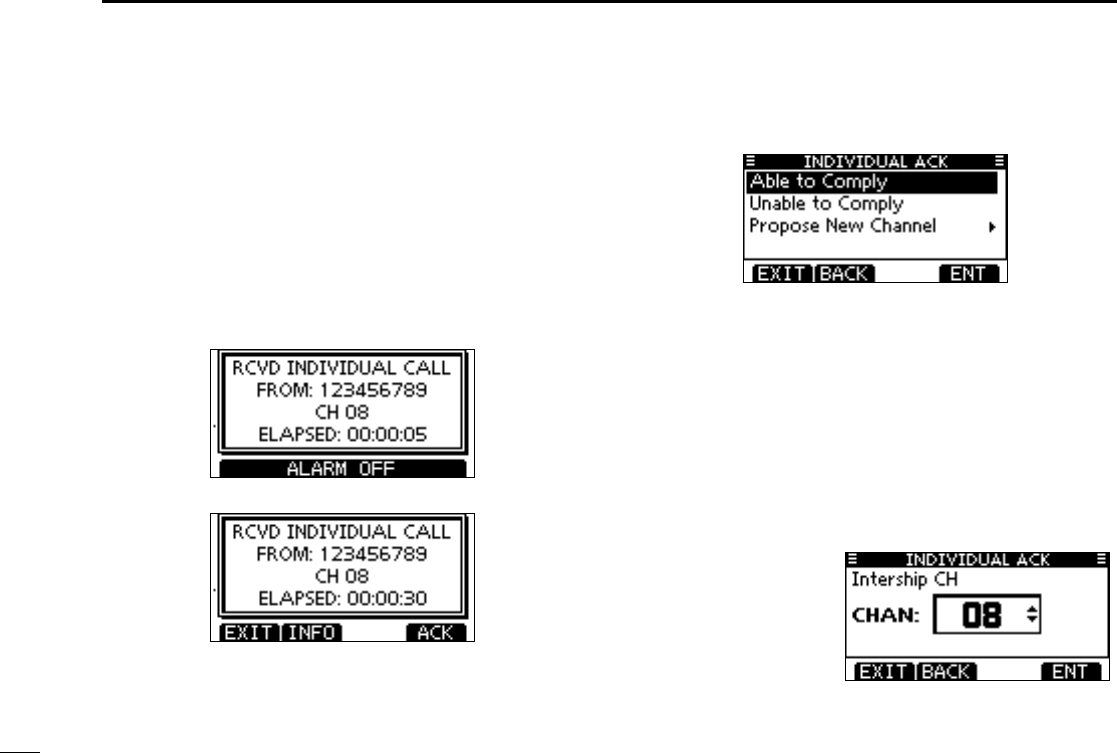
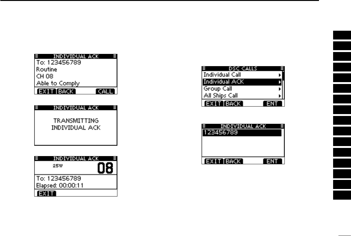
Transmitting an Individual Acknowledgement D
When receiving an Individual call, you can transmit an ac-
knowledgement (‘Able to Comply,’ ‘Propose New Channel’ or
‘Unable to Comply’) by using the on-screen prompts (Quick
ACK.) Also, you can send an acknowledgement through the
MENU system (Man ual ACK.)
Quick ACK:
When q an Individual call is received, beeps sound and the
screen as shown below is displayed.
Push [ALARM OFF] to stop the beeps.
Push [ACK]. w
Select one of three options, then push [ENT]. e
•AbletoComply :Makeanacknowledgmentcallwithout
any changes.
•UnabletoComply :You cannot make an acknowledge-
ment call.
The Acknowledgement call (‘Unable
to Comply’) can be automatically
transmitted, if set. See page 61 for de-
tails.
•ProposeNewChannel:You can make an acknowledgement
call, but you specify the intership
channel. Select a desired intership
channel, using Dial, or [Y](CH)/[Z]
(CH), then push [ENT].
30
8
DSC OPERATION
1
2
3
4
5
6
7
8
9
10
11
12
13
14
15
16
The Individual ACK confirmation screen is displayed. r
Push [CALL] to transmit an acknowledgement call.
Following screens as shown below are displayed. t
Comply to the call using the microphone. y
Push [EXIT] to return to the normal operating mode. u
Manual ACK:
Enter “INDIVIDUAL ACK” in the DSC CALLS menu. q
•When no Individual call has been received, “Individual ACK”
item will not be displayed.
Select a desired individual address or ID code to reply to, w
using Dial or [Y]/[Z], then push [ENT].
Perform steps e e to u, as described in “Quick ACK:” to
the left.
31
1CHAPTER_CONTINUED
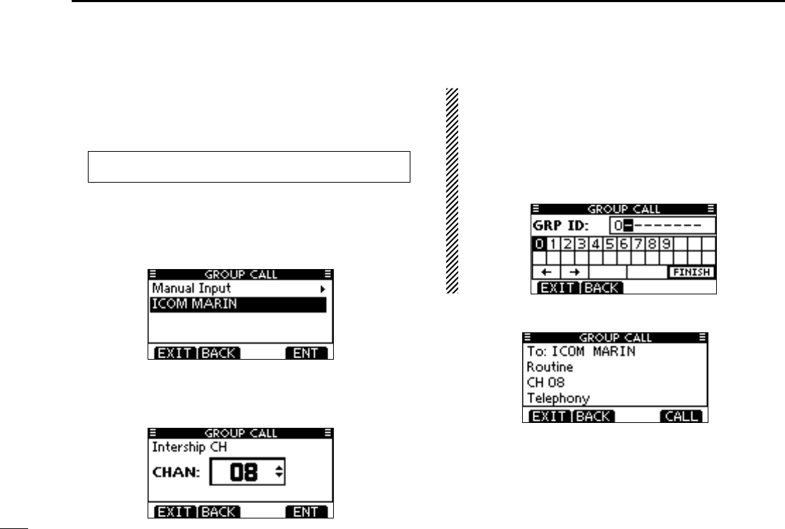
Transmitting a Group call D
The Group call function allows you to transmit a DSC signal
to only a specific group.
Enter “GROUP CALL” in the DSC CALLS menu. q
Select the desired preprogrammed group address or w
“Manual Input,” using [Y]/[Z], then push [ENT].
•TheIDcodefortheGroupcallcanbesetrst.(p.20)
•When“ManualInput”isselected,setthe8digitIDcodeforthe
group you wish to call.
Select a desired intership channel using [ eY](CH)/[Z](CH),
then push [ENT].
•Intershipchannelsarealreadypresetintothetransceiverinthe
recommended order.
About Manual Inputting:
Enter a desired group ID in the following way:
•Selectadesirednumberusing[Y]/[Z]/[Ω]/[≈].
•Push[ENT]tosetit.
•Tomovethecursor,selecteitherarrow,“←” or “→,” then push
[ENT].
•Therstdigitisspeciedas‘0’foraGroupID.
•Thersttwodigitsare‘0’foranyCoaststationID.
A confirmation screen appears. r
•Conrmthecallcontents.
MENU ➪ DSC Calls ➪ Group Call
(Push [MENU])
(Push
[Y]/[Z]
, then push [ENT].)
32
8
DSC OPERATION
1
2
3
4
5
6
7
8
9
10
11
12
13
14
15
16
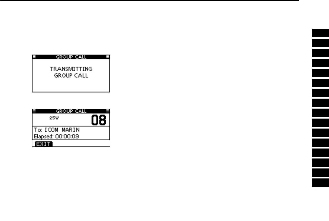
Push [CALL] to transmit the Group call. t
•IfChannel70isbusy,thetransceiverstandsbyuntilthechan-
nel becomes clear.
After the Group call has been transmitted, the following y
screen is displayed.
Announce the information using the microphone. u
After the announcement, push [EXIT] to return to the nor- i
mal operating mode.
33
8DSC OPERATION
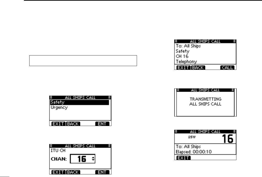
Transmitting an All Ships call D
All ships, that have DSC transceiver, use Channel 70 as their
‘listening channel.’ When you want to announce a message
to these ships within range, use the ‘All Ships Call’ function.
Enter “ALL SHIPS CALL” in the DSC CALLS menu. q
Select a desired category, using [ wY]/[Z], then push
[ENT].
•The selectable categories may differ, depending on the pro-
grammed setting. Ask your dealer for the selectable catego-
ries.
Select a desired traffic channel, using [ eY]/[Z], then push
[ENT].
•Theselectedchannelisdisplayed.
A confirmation screen appears. r
•Conrmthecallcontents.
Push [CALL] to transmit the All Ships call. t
•IfChannel70isbusy,thetransceiverstandsbyuntilthechan-
nel becomes clear.
After the All Ships call has been transmitted, the following y
screen is displayed.
Announce the message using the microphone. u
After the announcement, push [EXIT] to return to the nor- i
mal operating mode.
MENU ➪ DSC Calls ➪ All Ships Call
(Push [MENU])
(Push
[Y]/[Z]
, then push [ENT].)
34
8
DSC OPERATION
1
2
3
4
5
6
7
8
9
10
11
12
13
14
15
16
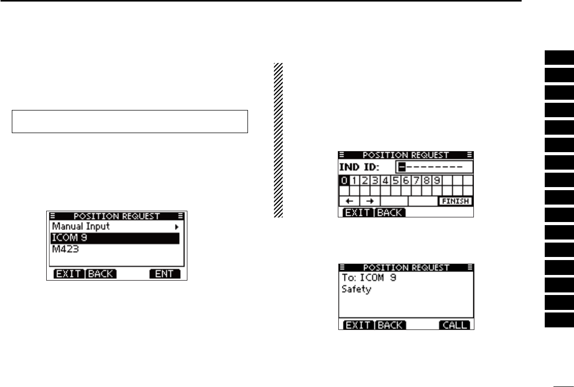
Transmitting a Position request call D
Transmit a Position request call when you want to know a
specific ship's current position.
Enter “POSITION REQUEST” in the DSC CALLS menu. q
Select the desired preprogrammed Position request ad- w
dress or “Manual Input,” using [Y]/[Z], then push [ENT].
•TheIDcodeforthePositionrequestcallcanbesetrst.
(p. 20)
•When“ManualInput”isselected,setthe8digitIDcodeforthe
group you wish to call.
About Manual Inputting:
Enter a desired address ID in the following way:
•Selectthedesirednumberusuing[Y]/[Z]/[Ω]/[≈].
•Push[ENT]tosetit.
•Tomovethecursor,selecteitherarrow,“←” or “→,” then push
[ENT].
•Therstdigitisspeciedas‘0’foraGroupID.
•Thersttwodigitsare‘0’foranyCoaststationID.
A confirmation screen appears. e
•Conrmthecallcontents.
☞ Continued on the next page.
MENU ➪ DSC Calls ➪ All Ships Call
(Push [MENU])
(Push
[Y]/[Z]
, then push [ENT].)

36
1
DSC OPERATION
1
2
3
4
5
6
7
8
9
10
11
12
13
14
15
16
Transmitting a Position report call D

39
8DSC OPERATION
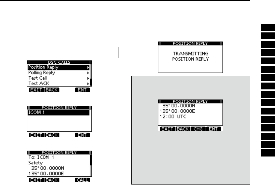
Transmitting a Position Reply call D
Transmit a Position Reply call when a Position Request call
is received.
When the “POSITION ACK” in DSC Settings is set to ‘Auto
TX’ (p. 61), the transceiver automatically transmits a reply
call when receiving a Position Request call.
Quick Reply:
When q a Position Request call is received, beeps sound
and the screen as shown below is displayed.
Push [ALARM OFF] to stop the beeps.
Push [ACK]. w
•Push[INFO]todisplaythePositionRequestcallinformation.
Push [BACK] to return to the previous screen, or push [ACK].
The Position Reply confirmation screen is displayed. e
Push [CALL] to transmit the reply call.
While transmitting the reply call, the screen as shown be- r
low is displayed, and then returns to the normal operating
mode.
40
8
DSC OPERATION
1
2
3
4
5
6
7
8
9
10
11
12
13
14
15
16
Manual Reply:
Enter “POSITION REPLY” in the DSC CALLS menu. q
•IfnoPositionRequestcallhasbeenreceived,the“POSITION
REPLY” item will not be displayed.
Select a desired Position Request call to reply to, using w
[Y]/[Z], then push [ENT].
The Position Reply call confirmation screen is displayed. e
Push [CALL] to transmit the acknowledgement call.
While transmitting the reply call, the screen as shown be- r
low is displayed, and then returns to the normal operating
mode.
When no GPS receiver is connected, and both position
and time have been manually programmed, the screen as
shown below appears. Edit your latitude and longitude posi-
tion and UTC time data as follows:
Push [CHG], then edit your latitude and longitude position
and UTC time data.
•Selectadesirednumberusing[Y]/[Z]/[Ω]/[≈].
•Push[ENT]tosetit.
•Tomovethecursor,selecteitherarrow,“←” or “→,” then push
[ENT].
•SelectN:NorthlatitudeorS:Southlatitudewhenthecursor
is on the ‘N’ or ‘S’ position.
•SelectW:WestlongitudeorE:Eastlongitudewhenthecur-
sor is on the ‘W’ or ‘E’ position.
MENU ➪ DSC Calls ➪ Position Reply
(Push [MENU])
(Push
[Y]/[Z]
, then push [ENT].)
41
8DSC OPERATION
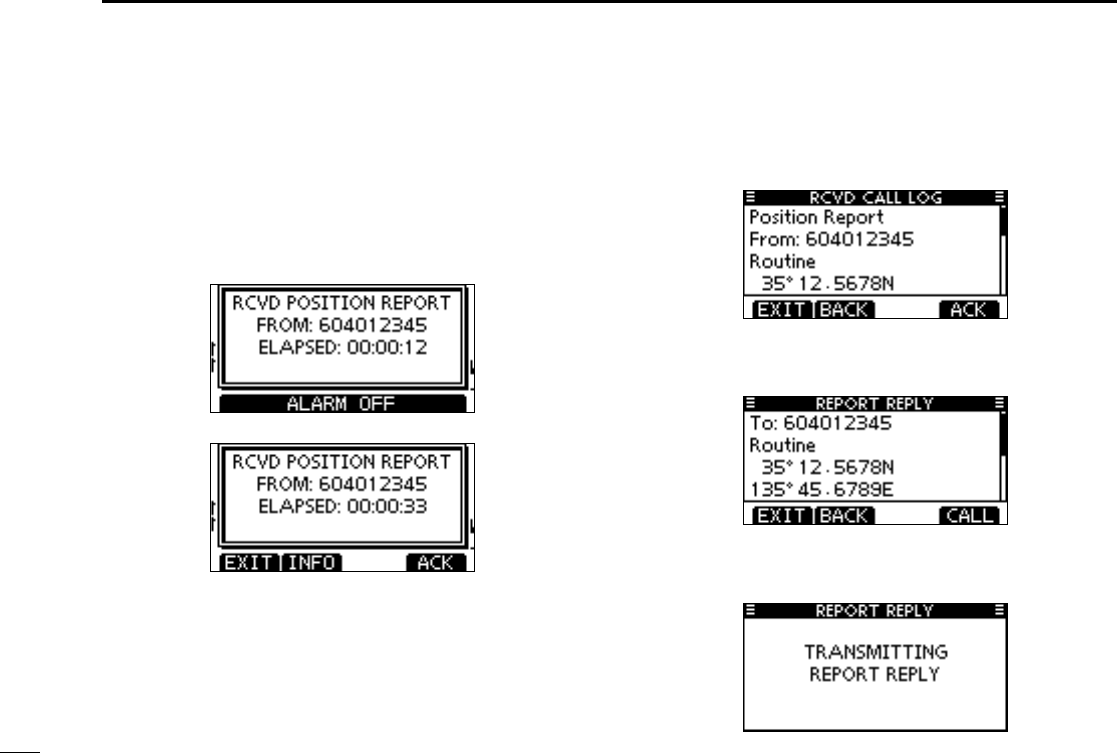
Transmitting a Position Report Reply call D
Transmit a Position Report Reply call when a Position Report
Request call is received.
Quick Reply:
When q a Position Report Request call is received, beeps
sound and the screen as shown below is displayed.
Push [ALARM OFF] to stop the beeps.
Push [ACK]. w
•Push[INFO]todisplaythePositionReportRequestcallinfor-
mation.
Push [BACK] to return to the previous screen, or push [ACK].
The Position Report Reply confirmation screen is dis- e
played.
Push [CALL] to transmit the reply call.
While transmitting the reply call, the screen as shown be- r
low is displayed, and then returns to the normal operating
mode.
42
8
DSC OPERATION
1
2
3
4
5
6
7
8
9
10
11
12
13
14
15
16
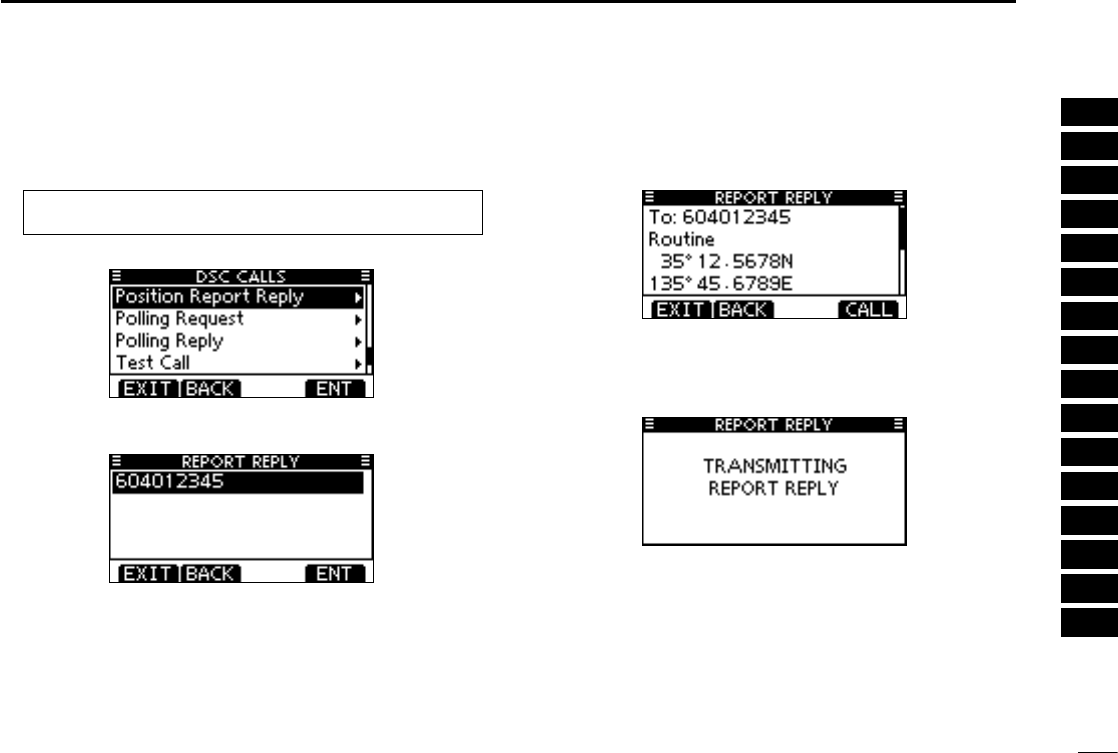
Manual Reply:
Enter “POSITION REPORT REPLY” in the DSC CALLS q
menu.
•IfnoPositionReportRequestcallhasbeenreceived,the“PO-
SITION REPORT REPLY” item will not be displayed.
Select a desired Position Report Request call to be re- w
plied, using [Y]/[Z], then push [ENT].
The Position Report Reply call confirmation screen is dis- e
played.
Push [CALL] to transmit the acknowledgement call.
While transmitting the reply call, the screen as shown be- r
low is displayed, and then returns to the normal operating
mode.
MENU ➪ DSC Calls ➪ Position Report Reply
(Push [MENU])
(Push
[Y]/[Z]
, then push [ENT].)
43
8DSC OPERATION
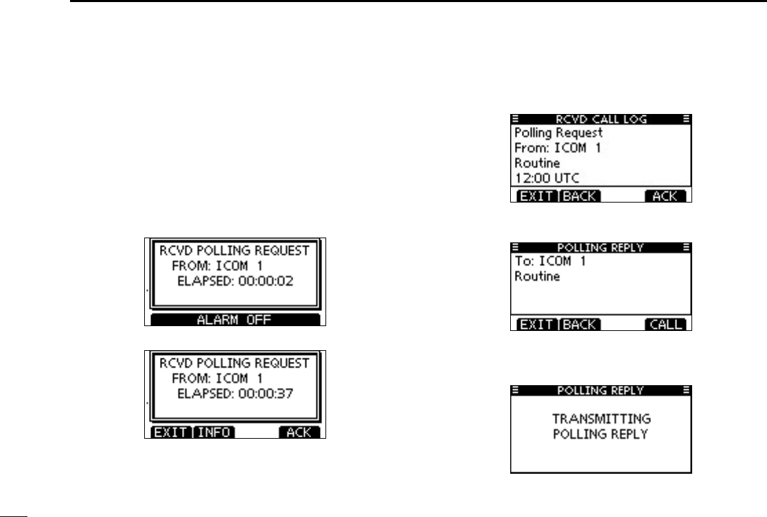
Transmitting a Polling Reply call D
Transmit a Polling Reply call when a Polling Request call is
received.
When the “POSITION ACK” in DSC Settings is set to ‘Auto
TX’ (p. 61), the transceiver automatically transmits a reply
call when receiving a Polling Request call.
Quick Reply:
When q a Polling Request call is received, beeps sound and
the screen as shown below is displayed.
Push [ALARM OFF] to stop the beeps.
Push [ACK]. w
•Push[INFO]todisplaythePollingRequestcallinformation.
Push [BACK] to return to the previous screen, or push [ACK].
The ePolling Reply confirmation screen is displayed.
Push [CALL] to transmit the reply call.
While transmitting the reply call, the screen as shown be- r
low is displayed, and then returns to the normal operating
mode.
44
8
DSC OPERATION
1
2
3
4
5
6
7
8
9
10
11
12
13
14
15
16
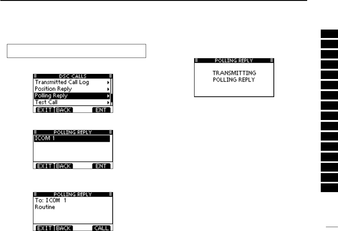
Manual Reply:
Enter “POLLING REPLY” in the DSC CALLS menu. q
•If no Polling Request call has been received, the “POLLING
REPLY” item will not be displayed.
Select a desired Polling Request call to be replied, using w
[Y]/[Z], then push [ENT].
The Position Polling Reply call confirmation screen is dis- e
played.
Push [CALL] to transmit the acknowledgement call.
While transmitting the reply call, the screen as shown be- r
low is displayed, and then returns to the normal operating
mode.
MENU ➪ DSC Calls ➪ Polling Reply
(Push [MENU])
(Push
[Y]/[Z]
, then push [ENT].)
45
8DSC OPERATION
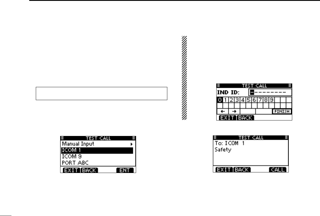
Transmitting a Test call D
Testing on the exclusive DSC distress and safety calling
channels should be avoided as much as possible. When test-
ing on the distress/safety channel is unavoidable, you should
indicate that these are test transmissions.
Normally the test call would require no further communica-
tions between the two stations involved.
Enter “TEST CALL” in the DSC CALLS menu. q
Select a desired preprogrammed individual address, or w
“Manual Input,” then push [ENT].
•TheIDcodefortheIndividualcallcanbesetrst.(p.19)
•When“ManualInput”isselected,setthe9digitMMSIIDcode
for the individual you wish to call.
About Manual Inputting:
Enter a desired address ID in the following way:
•Selectadesirednumberusing[Y]/[Z]/[Ω]/[≈].
•Push[ENT]tosetit.
•Tomovethecursor,selecteitherarrow,“←” or “→,” then push
[ENT].
•Therstdigitisspeciedas‘0’foraGroupID.
•Thersttwodigitsare‘0’foranyCoaststationID.
A confirmation screen appears. e
•Conrmthecallcontents.
MENU ➪ DSC Calls ➪ Test Call
(Push [MENU])
(Push
[Y]/[Z]
, then push [ENT].)
46
8
DSC OPERATION
1
2
3
4
5
6
7
8
9
10
11
12
13
14
15
16
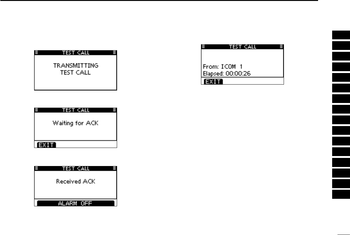
Push [CALL] to transmit the Test call. r
•IfChannel70isbusy,thetransceiverstandsbyuntilthechan-
nel becomes clear.
After the Test call has been transmitted, the following t
screen is displayed.
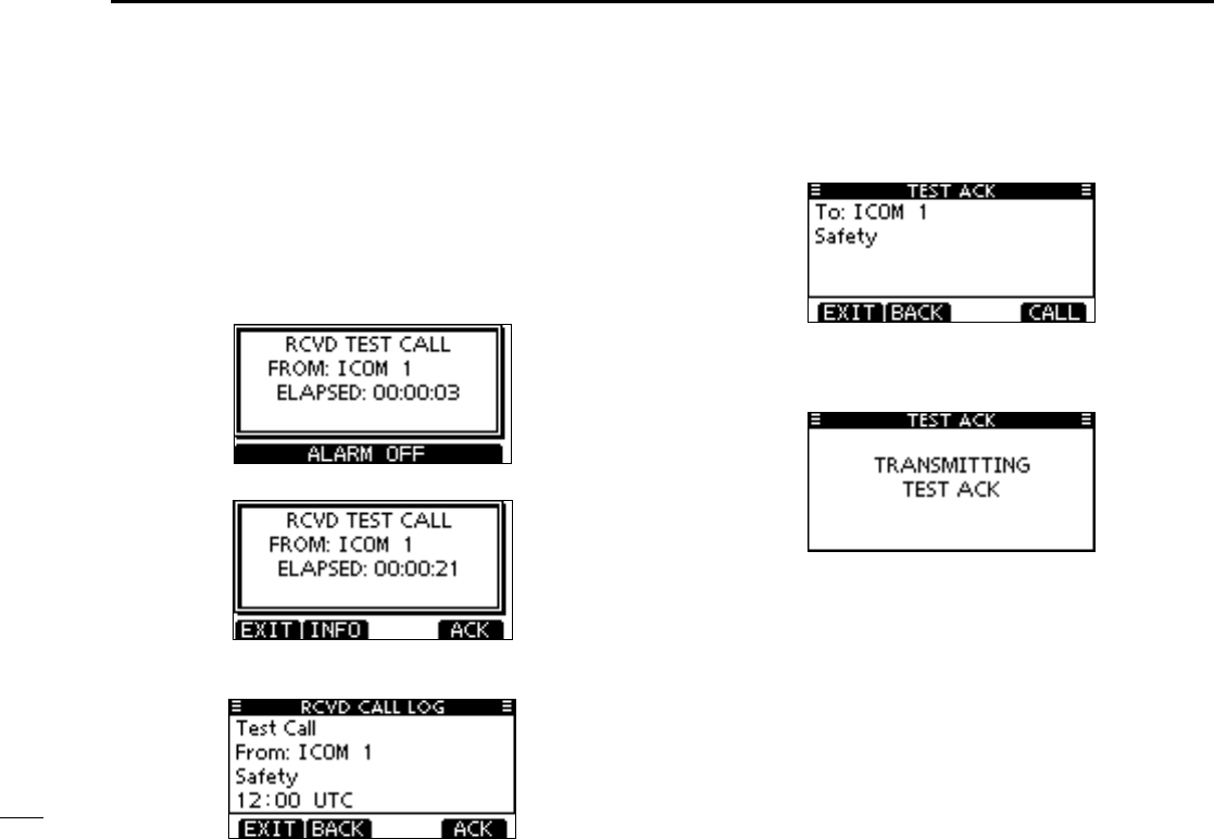
When the acknowledgement call is received, beeps sound y
and the following screen is displayed.
Push [ALARM OFF] to stop the beeps, and then the screen u
as shown below is displayed.
Push [EXIT] to return to the normal operating mode. i
47
8DSC OPERATION
Transmitting a Test Acknowledgement call D
When the “TEST ACK” in DSC settings is set to ‘Auto TX’
(p. 61), the transceiver automatically transmits a reply call
when receiving a Test call.
Quick ACK:
When q a Test call is received, beeps sound and the screen
as shown below is displayed.
Push [ALARM OFF] to stop the beeps.
Push [ACK]. w
•Push[INFO]todisplaytheTestcallinformation.
Push [BACK] to return to the previous screen, or push [ACK].
The Test ACK confirmation screen is displayed. e
Push [CALL] to transmit the acknowledgement call.
While transmitting the acknowledgement call, the screen r
as shown below is displayed, and then returns to the nor-
mal operating mode.
48
8
DSC OPERATION
1
2
3
4
5
6
7
8
9
10
11
12
13
14
15
16
Manual ACK:
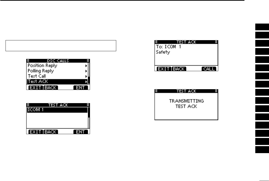
Enter “TEST ACK” in the DSC CALLS menu. q
•IfnoTestcallhasbeenreceived,the“TESTACK”itemwillnot
be displayed.
Select a desired Test call to reply to, using [ wY]/[Z], then
push [ENT].
The Test ACK confirmation screen is displayed. e
Push [CALL] to transmit the acknowledgement call.
While transmitting the acknowledgement call, the screen r
as shown below is displayed, and then returns to the nor-
mal operating mode.
MENU ➪ DSC Calls ➪ Test ACK
(Push [MENU])
(Push
[Y]/[Z]
, then push [ENT].)
49
8DSC OPERATION
Receiving DSC calls ■
Receiving a Distress Call D
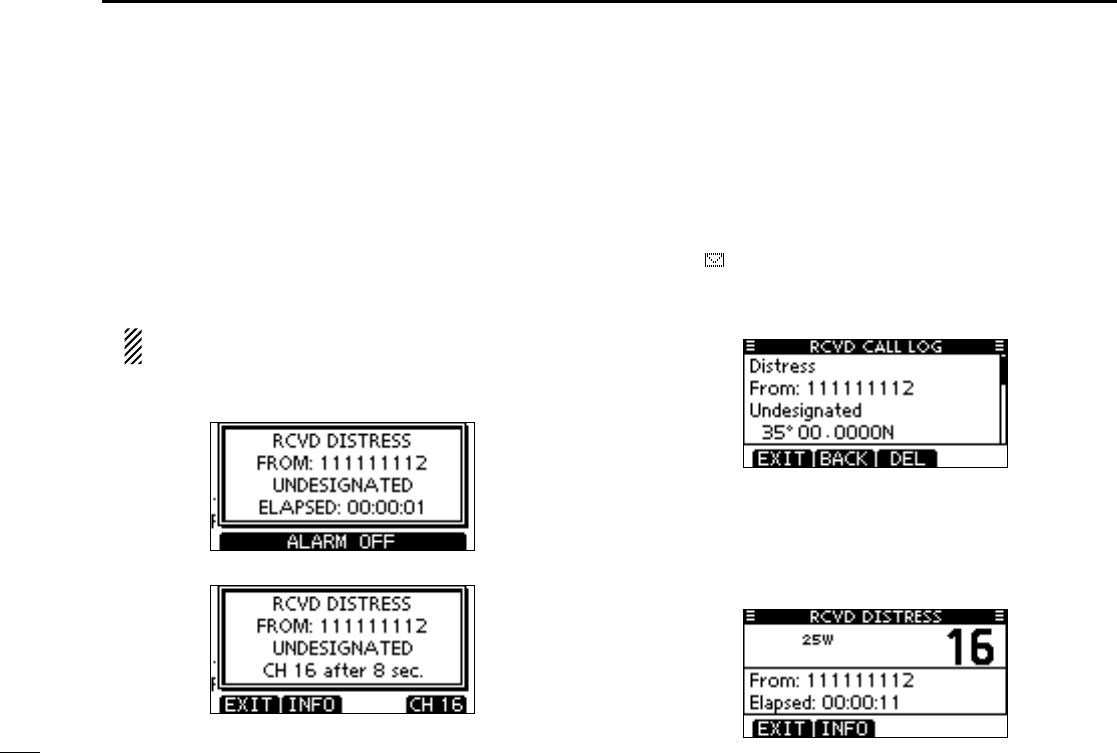
When a Distress Call is received:
➥ The emergency alarm sounds.
➥ “RCVD DISTRESS” pops up and the LCD backlight
blinks.
➥ Continue monitoring the current operating channel for 10
seconds. After that, the transceiver automatically switches
to Channel 16.
This action may differ, depending on the CH16 Switch
setting. See page 62 for more details.
Push [ALARM OFF] to stop the alarm and the backlight q
blinking.
Push either softkey to select a desired action. w
[EXIT]
➥Push to return to the normal operating mode.
•ThetransceiverexitstheDSCmode.
•By pushing [PTT], the transceiver also exits the DSC
mode.
•“ ” continues to blink and the Call is stored in the Re-
ceived Call Log.
[INFO]
➥Push to display the Received call information. (p. 58)
[CH 16]
➥ Push to switch the operating channel to Channel 16,
and monitor Channel 16, as a coast station may require
assistance.
•Ifyouhaven’tpushedanykeywithin10seconds,theoper-
ating channel automatically switches to Channel 16.
50
8
DSC OPERATION
1
2
3
4
5
6
7
8
9
10
11
12
13
14
15
16
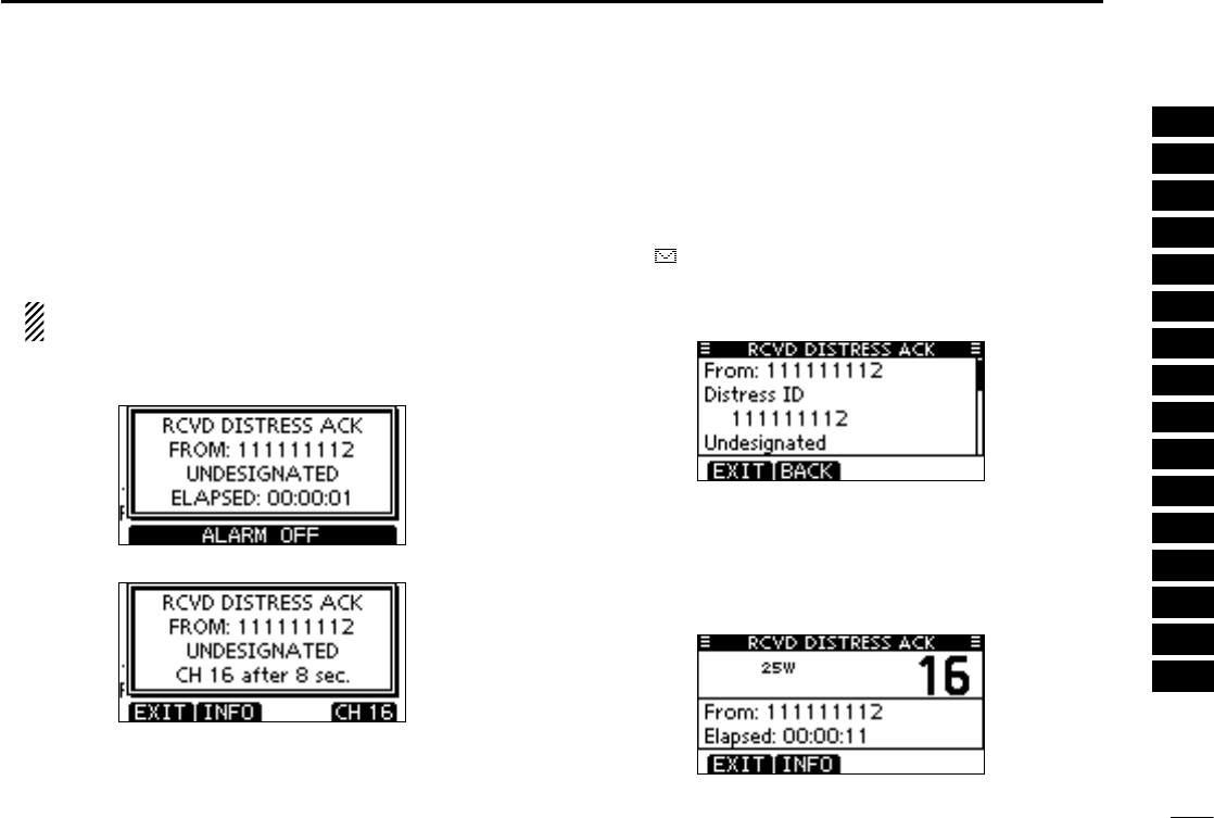
Receiving a Distress Acknowledgement D
When a Distress Acknowledgement to other ship is received:
➥ The emergency alarm sounds.
➥ “RCVD DISTRESS ACK” pops up and the LCD backlight
blinks.
➥ Continue monitoring the current operating channel for 10
seconds. After that, the transceiver automatically switches
to Channel 16.
This action may differ, depending on the CH16 Switch
setting. See page 62 for more details.
Push [ALARM OFF] to stop the alarm and the backlight q
blinking.
Push either softkey to select a desired action. w
[EXIT]
➥Push to return to the normal operating mode.
•ThetransceiverexitstheDSCmode.
•By pushing [PTT], the transceiver also exits the DSC
mode.
•“ ” continues to blink and the Call is stored in the Re-
ceived Call Log.
[INFO]
➥Push to display the Received call information. (p. 58)
[CH 16]
➥ Push to switch the operating channel to Channel 16,
and monitor Channel 16, as a coast station may require
assistance.
•Ifyouhaven’tpushedanykeywithin10seconds,theoper-
ating channel also switches to Channel 16.
51
8DSC OPERATION
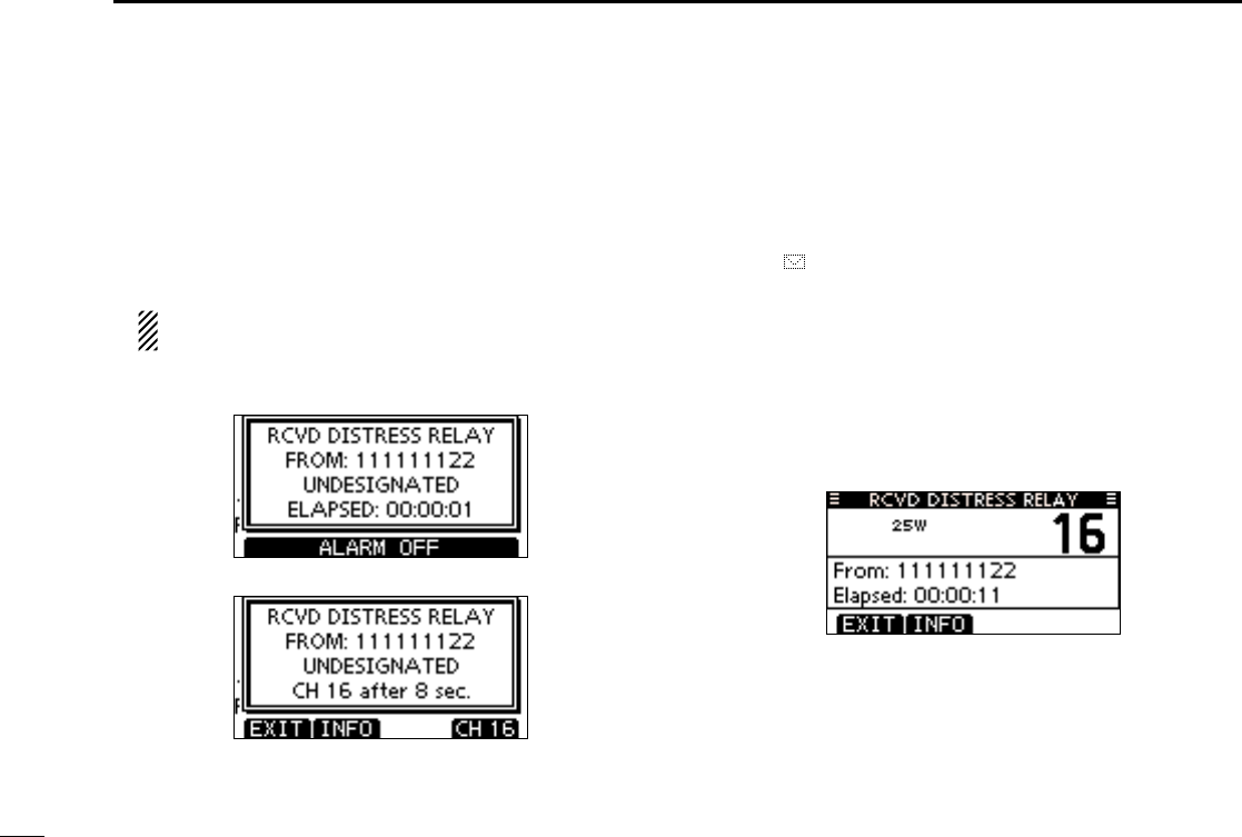
Receiving D a Distress Relay Call
When a Distress Relay call is received:
➥ The emergency alarm sounds.
➥ “RCVD DISTRESS RELAY” pops up and the LCD back-
light blinks.
➥ Continue monitoring the current operating channel for 10
seconds. After that, the transceiver automatically switches
to Channel 16.
This action may differ, depending on the CH16 Switch
setting. See page 62 for more details.
Push [ALARM OFF] to stop the alarm and the backlight q
blinking.
Push either softkey to select a desired action. w
[EXIT]
➥Push to return to the normal operating mode.
•ThetransceiverexitstheDSCmode.
•By pushing [PTT], the transceiver also exits the DSC
mode.
•“ ” continues to blink and the Call is stored in the Re-
ceived Call Log.
[INFO]
➥Push to display the Received call information. (p. 58)
[CH 16]
➥ Push to switch the operating channel to Channel 16,
and monitor Channel 16, as a coast station may require
assistance.
•Ifyouhaven’tpushedanykeywithin10seconds,theoper-
ating channel also switches to Channel 16.
52
8
DSC OPERATION
1
2
3
4
5
6
7
8
9
10
11
12
13
14
15
16
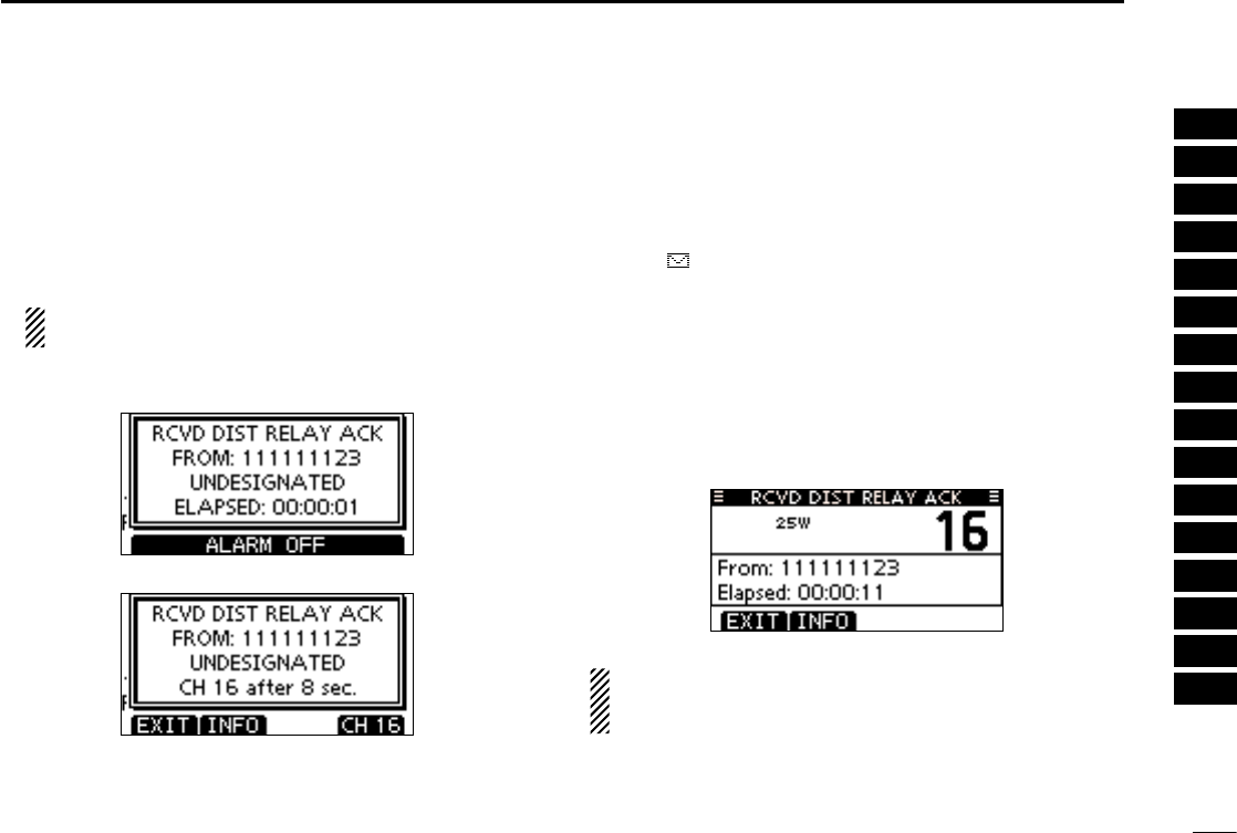
Receiving D a Distress Relay Acknowledgement
When a Distress Relay Acknowledgement is received:
➥ The emergency alarm sounds.
➥ “RCVD DIST RELAY ACK” pops up and the LCD backlight
blinks.
➥ Continue monitoring the current operating channel for 10
seconds. After that, the transceiver automatically switches
to Channel 16.
This action may differ, depending on the CH16 Switch
setting. See page 62 for more details.
Push [ALARM OFF] to stop the alarm and the backlight q
blinking.
Push either softkey to select a desired action. w
[EXIT]
➥Push to return to the normal operating mode.
•ThetransceiverexitstheDSCmode.
•By pushing [PTT], the transceiver also exits the DSC
mode.
•“ ” continues to blink and the Call is stored in the Re-
ceived Call Log.
[INFO]
➥Push to display the Received call information. (p. 58)
[CH 16]
➥ Push to switch the operating channel to Channel 16,
and monitor Channel 16, as a coast station may require
assistance.
•Ifyouhaven’tpushedanykeywithin10seconds,theoper-
ating channel also switches to Channel 16.
NOTE: If a duplicate call is received within 1 hour after
receiving the Distress Relay or Distress Relay Acknowl-
edgement call, the alarm does not sound.
53
8DSC OPERATION
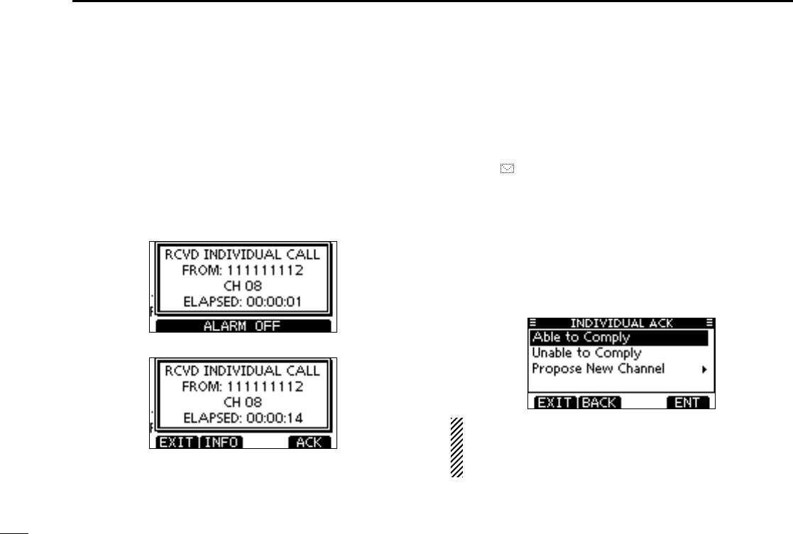
Receiving an Individual Call D
When an Individual Call is received:
➥ T he emergency alarm sounds for 2 minutes, depending on
the received Category.
➥ “RCVD INDIVIDUAL CALL” pops up. The LCD backlight
blinks for 2 minutes, depending on the received Category.
Push [ALARM OFF] to stop the alarm and the backlight q
blinking.
•Ifyouhaven’tpushed[ALARMOFF]within2minutes,thenext
screen automatically appears, depending on the received Cat-
egory.
Push either softkey to select a desired action. w
[EXIT]
➥
Push to ignore the Call and return to the normal operating
mode.
•ThetransceiverexitstheDSCmode.
•TheCallisstoredintheReceivedCallLog.
•“ ” continues to blink and the Call is stored in the Re-
ceived Call Log.
[INFO]
➥Push to display the Received call information. (p. 59)
[ACK]
➥ Push to display the “INDIVIDUAL ACK” screen to re-
ply to the Call, and select the channel specified by the
calling station for voice communication, depending on
your situation. See page 30 for details of the Individual
Acknowledgement procedure.
When “INDIVIDUAL ACK” is set to “Auto ACK (Unable),”
the transceiver automatically replies to the Call. In that
case, both the TX and RX calls are stored in the Transmit-
ted and Received Call Logs.
54
8
DSC OPERATION
1
2
3
4
5
6
7
8
9
10
11
12
13
14
15
16
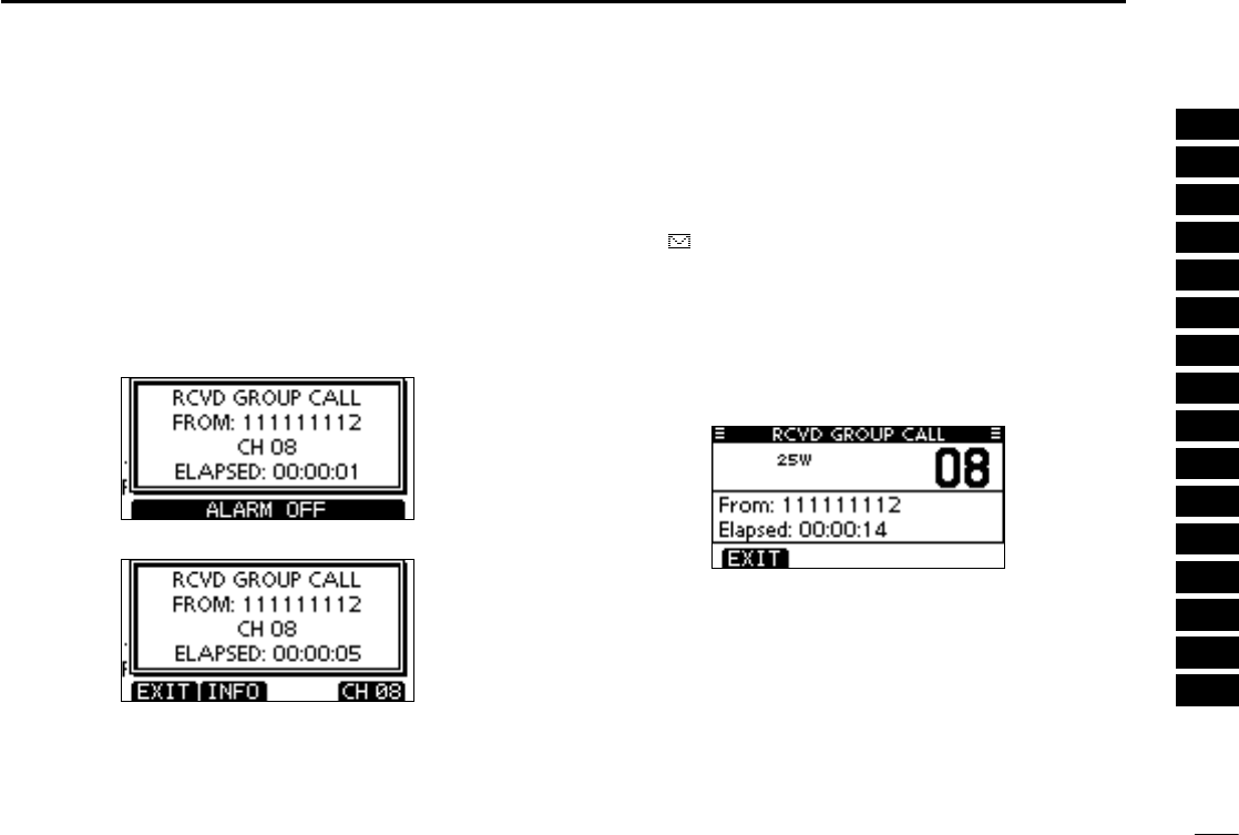
Receiving a Group Call D
When a Group Call is received:
➥ The emergency alarm sounds for 2 minutes, depending on
the received Category.
➥ “RCVD GROUP CALL” pops up. The LCD backlight blinks
for 2 minutes, depending on the received Category.
Push [ALARM OFF] to stop the alarm and the backlight q
blinking.
•Ifyouhaven’tpushed[ALARMOFF]within2minutes,thenext
screen automatically appears, depending on the received Cat-
egory.
Push either softkey to select a desired action. w
[EXIT]
➥Push to ignore the Call and return to the normal operat-
ing mode.
•ThetransceiverexitstheDSCmode.
•“ ” continues to blink and the Call is stored in the Re-
ceived Call Log.
[INFO]
➥Push to display the Received call information. (p. 59)
[CH xx*]
* xx is specified by the calling station. (Example: 08)
➥ Push to monitor the specified channel for an announce-
ment from the calling station.
55
8DSC OPERATION
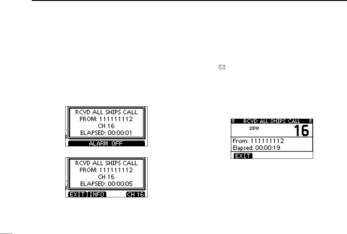
Receiving an All Ships Call D
When an All Ships Call is received:
➥ The emergency alarm sounds for 2 minutes, depending on
the received Category.
➥ “RCVD ALL SHIPS CALL” pops up. The LCD backlight
blinks for 2 minutes, depending on the received Category.
Push [ALARM OFF] to stop the alarm and the backlight q
blinking.
•Ifyouhaven’tpushed[ALARMOFF]within2minutes,thenext
screen automatically appears, depending on the received Cat-
egory.
Push either softkey to select a desired action. w
[EXIT]
➥Push to ignore the Call and return to the normal operat-
ing mode.
•ThetransceiverexitstheDSCmode.
•“ ” continues to blink and the Call is stored in the Re-
ceived Call Log.
[INFO]
➥Push to display the Received call information. (p. 59)
[CH xx*]
* xx is specified by the calling station. (Example: 16)
➥ Push to monitor the specified channel for an announce-
ment from the calling station.
56
8
DSC OPERATION
1
2
3
4
5
6
7
8
9
10
11
12
13
14
15
16
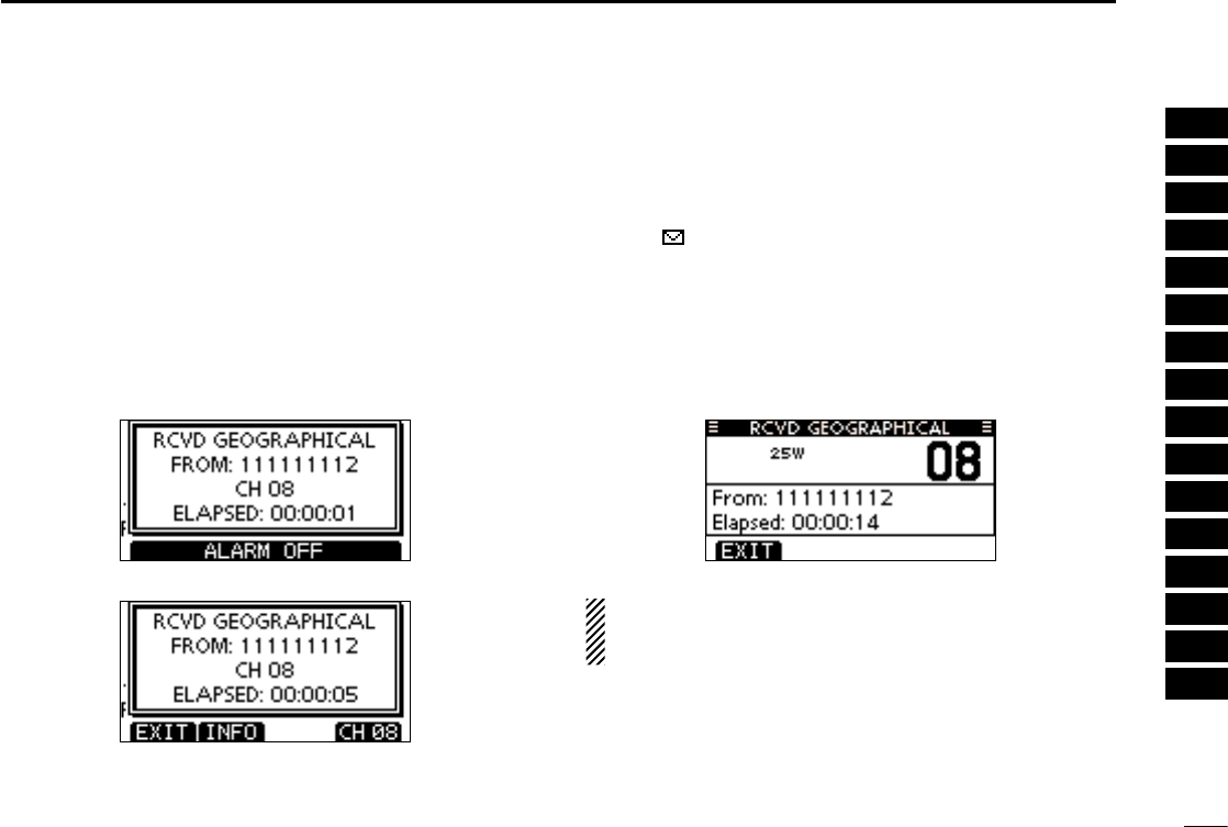
Receiving a Geographical Area Call D
When a Geographical Area Call (for the area you are in) is
received:
➥ The emergency alarm sounds for 2 minutes, depending on
the received Category.
➥ “RCVD GEOGRAPHICAL CALL” pops up. The LCD back-
light blinks for 2 minutes, depending on the received Cat-
egory.
Push [ALARM OFF] to stop the alarm and the backlight q
blinking.
•Ifyouhaven’tpushed[ALARMOFF]within2minutes,thenext
screen automatically appears, depending on the received Cat-
egory.
Push either softkey to select a desired action. w
[EXIT]
➥Push to ignore the Call and return to the normal operat-
ing mode.
•ThetransceiverexitstheDSCmode.
•“ ” continues to blink and the Call is stored in the Re-
ceived Call Log.
[INFO]
➥Push to display the Received call information. (p. 59)
[CH xx*]
* xx is specified by the calling station.
➥ Push to monitor the specified channel for an announce-
ment from the calling station.
When no GPS receiver is connected or if there is a prob-
lem with the connected receiver, all Geographical Area
Calls are received, regardless of your position.
57
8DSC OPERATION
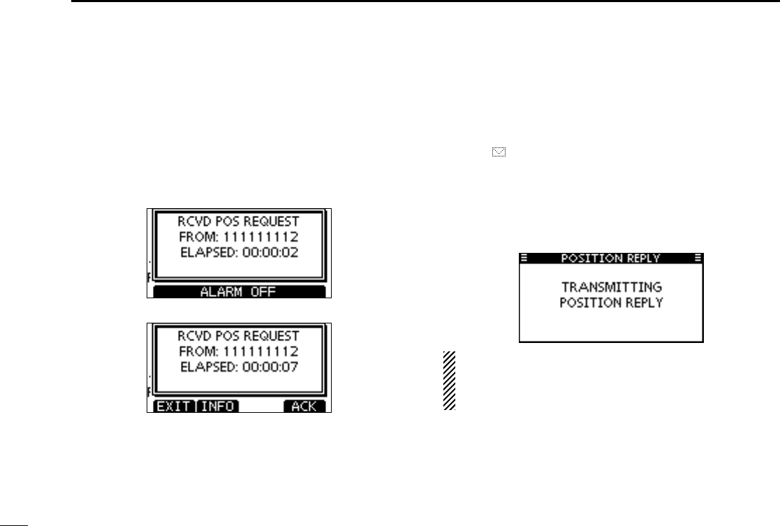
Receiving a Position Request Call D
When a Position Request Call is received:
➥ The emergency alarm sounds for 2 minutes.
➥ “RCVD POS REQUEST” pops up. The LCD backlight
blinks for 2 minutes.
Push [ALARM OFF] to stop the alarm and the backlight q
blinking.
•Ifyouhaven’tpushed[ALARMOFF]within2minutes,thenext
screen automatically appears.
Push either softkey to select a desired action. w
[EXIT]
➥Push to ignore the Call and return to the normal operat-
ing mode.
•ThetransceiverexitstheDSCmode.
•“ ” continues to blink and the Call is stored in the Re-
ceived Call Log.
[INFO]
➥Push to display the Received call information. (p. 59)
[ACK]
➥ Push to display the “POSITION REPLY” screen and
send a reply to the Call. (p. 39)
When “POSITION ACK” is set to “Auto TX,” the transceiv-
er automatically replies to the Call. In that case, both the
TX and RX calls are stored in the Transmitted and Re-
ceived Call Logs.
58
8
DSC OPERATION
1
2
3
4
5
6
7
8
9
10
11
12
13
14
15
16
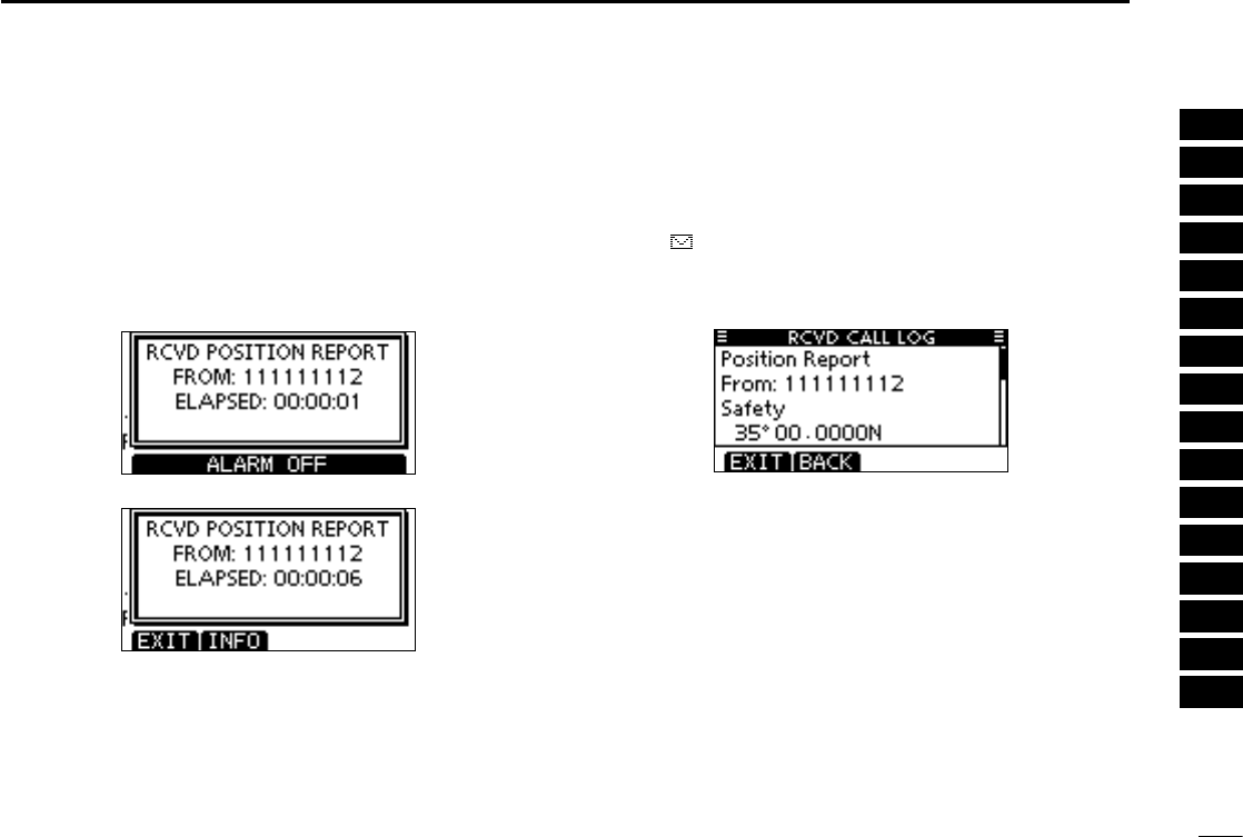
Receiving a Position Report Call D
When a Position Report Call is received:
➥ The emergency alarm sounds for 2 minutes.
➥ “RCVD POSITION REPORT” pops up. The LCD backlight
blinks for 2 minutes.
Push [ALARM OFF] to stop the alarm and the backlight q
blinking.
•Ifyouhaven’tpushed[ALARMOFF]within2minutes,thenext
screen automatically appears.
Push either softkey to select a desired action. w
[EXIT]
➥Push to ignore the Call and return to the normal operat-
ing mode.
•ThetransceiverexitstheDSCmode.
•“ ” continues to blink and the Call is stored in the Re-
ceived Call Log.
[INFO]
➥Push to display the Received call information. (p. 59)
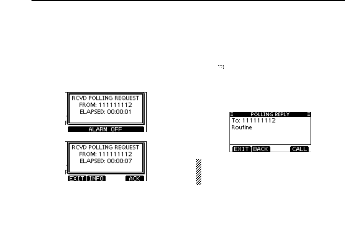
59
8DSC OPERATION
D Receiving a Polling Request call
When a Polling Request call is received:
➥ The emergency alarm sounds for 2 minutes.
➥ “RCVD POLLING REQUEST” pops up. The LCD backlight
blinks for 2 minutes.
Push [ALARM OFF] to stop the alarm and the backlight q
blinking.
•Ifyouhaven’tpushed[ALARMOFF]within2minutes,thenext
screen automatically appears.
Push either softkey to select a desired action. w
[EXIT]
➥Push to ignore the Call and return to the normal operat-
ing mode.
•ThetransceiverexitstheDSCmode.
•“ ” continues to blink and the Call is stored in the Re-
ceived Call Log.
[INFO]
➥Push to display the Received call information. (p. 58)
[ACK]
➥ Push to display the “POLLING REPLY” screen to reply
to the Call. (p. 43)
When “POSITION ACK” is set to “Auto TX,” the transceiver
automatically replies to the Call. In that case, both the TX
and RX calls are stored in the Transmitted and Received
Call Logs.
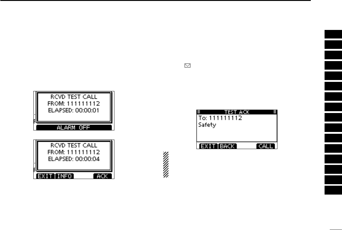
62
8
DSC OPERATION
1
2
3
4
5
6
7
8
9
10
11
12
13
14
15
16
D Receiving a Test Call
When a Test Call is received:
➥ The emergency alarm sounds for 2 minutes.
➥ “RCVD TEST CALL” pops up. The LCD backlight blinks for
2 minutes.
Push [ALARM OFF] to stop the alarm and the backlight q
blinking.
•Ifyouhaven’tpushed[ALARMOFF]within2minutes,thenext
screen automatically appears.
Push either softkey to select a desired action. w
[EXIT]
➥Push to ignore the Call and return to the normal operat-
ing mode.
•ThetransceiverexitstheDSCmode.
•“ ” continues to blink and the Call is stored in the Re-
ceived Call Log.
[INFO]
➥Push to display the Received call information. (p. 58)
[ACK]
➥ Push to display the “TEST ACK” screen to reply to the
Call. (p. 37)
When “TEST ACK” is set to “Auto TX,” the transceiver au-
tomatically replies to the Call. In that case, both the TX and
RX calls are stored in the Transmitted and Received Call
Logs.
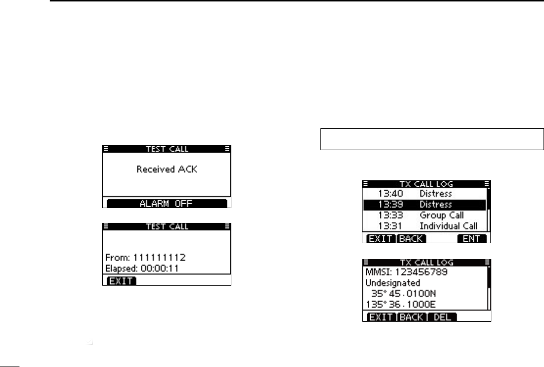
63
8DSC OPERATION
Receiving a Test Acknowledgement Call D
When a Test Acknowledgement Call is received:
➥ The emergency alarm sounds for 2 minutes.
➥ “RCVD TEST ACK” pops up. The LCD backlight blinks for
2 minutes.
Push [ALARM OFF] to stop the alarm and the backlight q
blinking.
•Ifyouhaven’tpushed[ALARMOFF]within2minutes,thenext
screen automatically appears.
Push either softkey to select a desired action. w
[EXIT]
➥Push to ignore the Call and return to the normal operat-
ing mode.
•ThetransceiverexitstheDSCmode.
•“ ” continues to blink and the Call is stored in the Re-
ceived Call Log.
Transmitted Call log ■
The transceiver automatically stores up to 50 transmitted
calls, and the logs can be used as a supplement to your log-
book.
Enter “TX CALL LOG” in the DSC CALLS menu. q
MENU ➪ DSC Calls ➪ Transmitted Call Log
(Push [MENU])
(Push
[p]/[q]
, then push [ENT].)
Push [ wp] or [q] to select the desired item, then push
[ENT].
Push e[p] or [q] to scroll the message contents.
To delete the displayed message, push [DEL]. r
•Theconrmationscreenappears,thenpush[OK]todelete.
Push [EXIT] to return to the normal operating mode. t
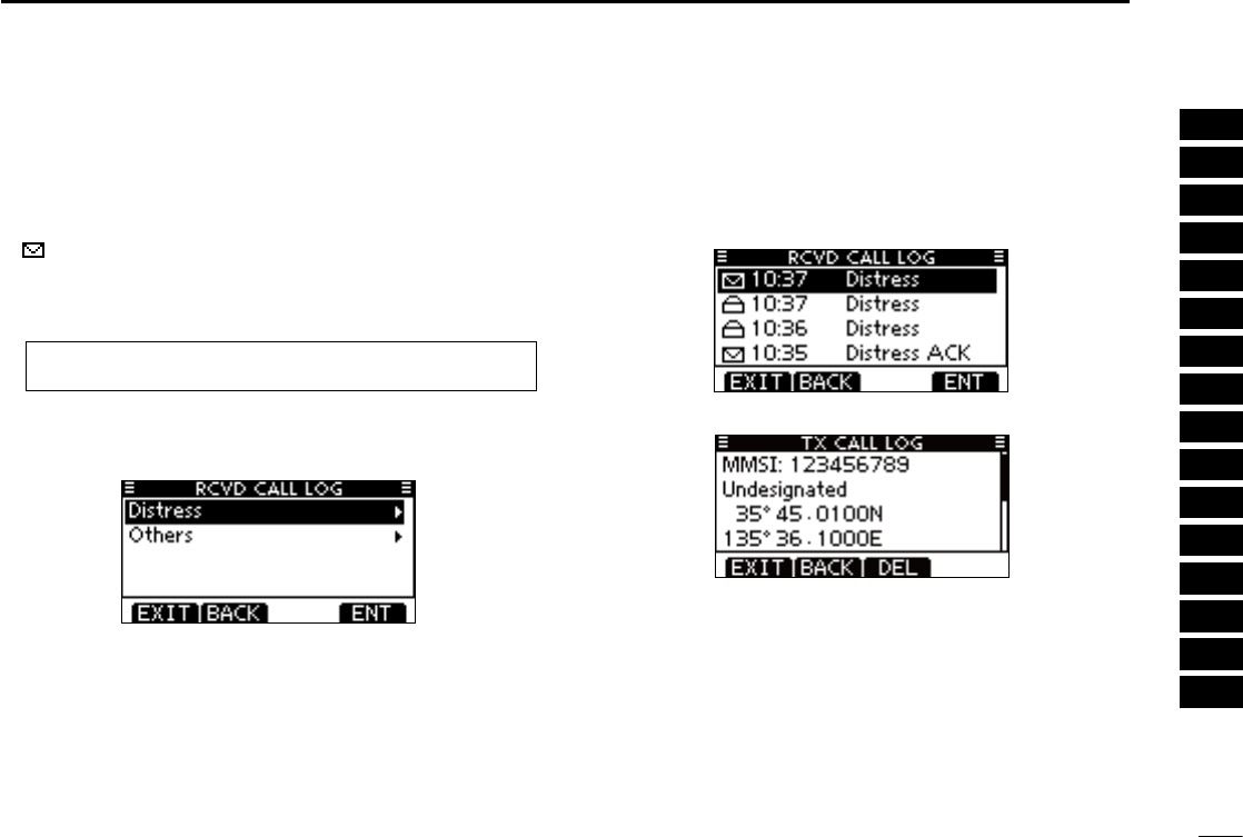
64
8
DSC OPERATION
1
2
3
4
5
6
7
8
9
10
11
12
13
14
15
16
Received Call log ■
The transceiver automatically stores up to 50 distress mes-
sages and 50 other messages, and the messages can be
used as a supplement to your logbook.
•“ ” blinks when there is an unread message.
Distress message D
Enter “RCVD CALL LOG” in the DSC CALLS menu. q
MENU ➪ DSC Calls ➪ Received Call Log
(Push [MENU])
(Push
[p]/[q]
, then push [ENT].)
Push [ wp] or [q] to select “Distress,” then push [ENT].
•Themessagesarestoredin“Distress,”ifitsformatspecieris
‘Distress.’
Push [ ep] or [q] to select the desired item, then push
[ENT].
•Themessageintheunopenedlehasnotbeenread.
Push r
[p]/[q] to scroll the message contents.
To delete the displayed message, push [DEL]. t
•Theconrmationscreenappears,thenpush[OK]todelete.
Push [EXIT] to return to the normal operating mode. y
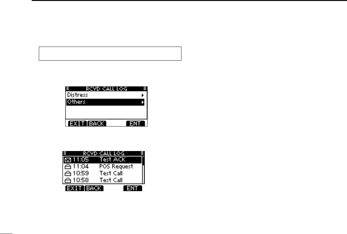
65
8DSC OPERATION
Other messages D
Enter “RCVD CALL LOG” in the DSC Calls menu. q
MENU ➪ DSC Calls ➪ Received Call Log
(Push [MENU])
(Push
[p]/[q]
, then push [ENT].)
Push [ wp] or [q] to select “Other,” then push [ENT].
•Themessagesarestoredin“Other,”ifitsformatspecierisoth-
er than ‘Distress.’
Push [ ep] or [q] to select the desired item, then push
[ENT].
•Themessageintheunopenedlehasnotbeenread.
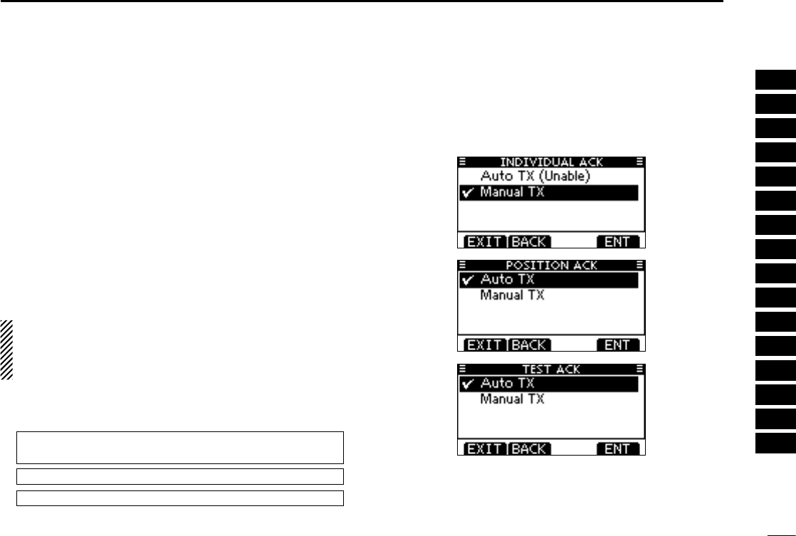
66
8
DSC OPERATION
1
2
3
4
5
6
7
8
9
10
11
12
13
14
15
16
DSC Settings ■
D Position Input (See page 22)
D Add Individual ID/Group ID (See pages 19, 20)
D Delete Individual ID/Group ID (See page 21)
D Automatic Acknowledgement
These items set the Automatic Acknowledgement function to
“Auto TX” or “Manual TX.”
When an Individual, Position Request, Position Report, Poll-
ing Request or Test Call is received, the transceiver auto-
matically transmits an Individual Acknowledgement, Position
Reply, Position Report Reply*, Polling Reply or Test Acknowl-
edgement Call, respectively.
*Only when the received Position Report call requires a reply.
When “INDIVIDUAL ACK” is set to “Auto TX,” the trans-
ceiver automatically transmits the Acknowledgment call
including “Unable to Comply” (No Reason Given) after re-
ceivng the Individual call.
q
Enter either “INDIVIDUAL ACK,” “POSITION ACK,” “TEST
ACK” in the DSC Settings menu.
MENU ➪ DSC Settings ➪
Individual ACK
(Push [MENU])
(Push
[p]/[q]
, then push [ENT].)
MENU ➪ DSC Settings ➪
Position ACK
MENU ➪ DSC Settings ➪
Test ACK
Rotate Dial w
to select “Auto TX” or “Manual TX,” then push
[ENT].
•Push[BACK]tocancelandreturntotheDSCSettingsmenu.
(default)
(default)
(default)
Push [EXIT] to return to the normal operating mode. e

67
10 BATTERY CHARGING
■ Battery caution
R DANGER! Use and charge only specified Icom battery pack with
Icom radios or Icom chargers. Only Icom battery packs are tested
and approved for use and charge with Icom radios or Icom chargers.
Using third-party or counterfeit battery packs or chargers may cause
smoke, fire, or cause the battery to burst.
D Battery caution
R DANGER! DO NOT hammer or otherwise impact the battery. Do
not use the battery if it has been severely impacted or dropped, or if
the battery has been subjected to heavy pressure. Battery damage
may not be visible on the outside of the case. Even if the surface
of the battery does not show cracks or any other damage, the cells
inside the battery may rupture or catch fire.
R DANGER! NEVER use or leave battery pack in areas with
temperatures above +60˚C (+140˚F). High temperature buildup in
the battery, such as could occur near fires or stoves, inside a sun-
heated car, or by setting the battery in direct sunlight may cause the
battery to rupture or catch fire. Excessive temperatures may also
degrade battery performance or shorten battery life.
R DANGER! DO NOT expose the battery to rain, snow, saltwater,
or any other liquids. Never charge or use a wet battery. If the battery
gets wet, be sure to wipe it dry before using. The battery by itself is
not waterproof.
R DANGER! NEVER incinerate a used battery pack since internal
battery gas may cause them to rupture or may cause an explosion.
R DANGER! NEVER solder the battery terminals, or NEVER
modify the battery pack. This may cause heat generation, and the
battery may rupture, emit smoke or catch fire.
R DANGER! Use the battery only with the transceiver for which it is
specified. Never use a battery with any other equipment, or for any
purpose that is not described in this instruction manual.
R DANGER!
If fluid from inside the battery gets in your eyes, blind-
ness can result. Rinse your eyes with clean water, without rubbing
them, and see a doctor immediately.WARNING! Immediately stop
using the battery if it emits an abnormal odor, heats up, or is discol-
ored or deformed. If any of these conditions occur, contact your Icom
dealer or distributor.
WARNING! Immediately wash, using clean water, any part of the
body that comes into contact with fluid from inside the battery.
WARNING!
NEVER put the battery in a microwave oven, high-
pressure container, or in an induction heating cooker. This could cause
overheating, a fire, or cause the battery to rupture.
CAUTION: Always use the battery within the specific temperature
range for the transceiver and the battery itself (–20˚C to +60˚C (-4˚F
to +140˚F)). Using the battery out of its specific temperature range
will reduce the battery’s performance and battery life. Please note
that the specified temperature range of the battery may exceed that
of the transceiver. In such cases, the transceiver may not work prop-
erly because it is out of its operating temperature range.
Misuse of Lithium-ion batteries may result in the follow-
ing hazards: smoke, fire, or the battery may rupture.
Misuse can also cause damage to the battery or deg-
radation of battery performance.

68
10
BATTERY CHARGING
1
2
3
4
5
6
7
8
9
10
11
12
13
14
15
16
CAUTION: Shorter battery life could occur if the battery is left fully
charged, completely discharged, or in an excessive temperature en-
vironment (above +50˚C (+122˚F)) for an extended period of time. If
the battery must be left unused for a long time, it must be detached
from the radio after discharging. You may use the battery until the
remaining capacity is about half, then keep it safely in a cool dry
place with the temperature range as follows:
–20˚C to +50˚C (–4˚F to +122˚F) (within a month)
–20˚C to +35˚C (–4˚F to +122˚F) (within three months)
–20˚C to +25˚C (–4˚F to +122˚F) (within a year)
D Charging caution
Charge the battery pack at least once every six months, even if it
has been not used for a long period of time. The battery pack will
have slowly self-discharged, even though it has not been used. If the
battery pack is left for a long period without being charged, its life
cycle will be shorter, or worse, it will never accept a charge again.
Due to the characteristics of the Li-ion rectangular battery, the
battery pack may change its shape as the charge and discharge
cycles are repeated. This is a normal phenomenon, and it is quite
safe to continue to use the pack, as long as it is properly handled.
However, when the shape of the battery pack is so changed that
the battery pack or battery cover can not be correctly attached to
the transceiver, it is time to replace it with a new one. Otherwise, the
transceiver can be damaged due to the loss of air tightness.
R DANGER! NEVER charge the battery pack in areas with ex-
tremely high temperatures, such as near fires or stoves, inside
a sun-heated car, or in direct sunlight. In such environments, the
safety/protection circuit in the battery will activate, causing the bat-
tery to stop charging.
WARNING! DO NOT charge or leave the battery in the battery char-
ger beyond the specified time for charging. If the battery is not com-
pletely charged by the specific time, stop charging and remove the
battery from the battery charger. Continuing to charge the battery
beyond the specific time limit may cause a fire, overheating, or the
battery may rupture.
WARNING! NEVER insert the transceiver (battery attached to the
transceiver) into the charger if it is wet or soiled. This could corrode
the battery charger terminals or damage the charger. The charger is
not waterproof.
CAUTION: DO NOT charge the battery outside of the specified
temperature range: ±0˚C to +45˚C (+32˚F to +113˚F). Icom recom-
mends charging the battery at +20˚C (+68˚F). The battery may heat
up or rupture if charged out of the specified temperature range, and
battery performance or battery life may be reduced.
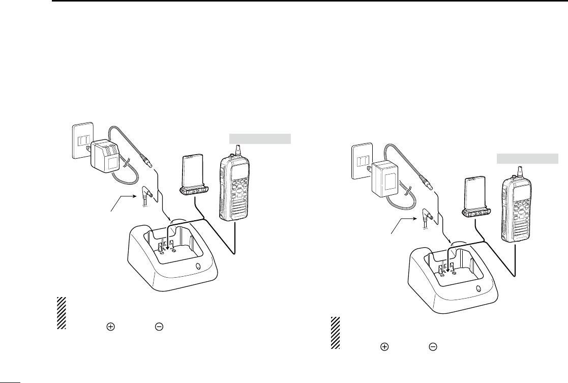
69
10BATTERY CHARGING
Regular battery charger ■
Regular charging with the BC-204 + BC-147S D
The supplied BC-204 with BC-147 provide regular charging
of the Li-ion battery pack.
BC-147S
CP-25 or optional
OPC-515L* (for
13.8 V power
source) or CP-23L
(for 12 V cigarette
lighter socket) can
be used instead of
the AC adapter.
TransceiverBattery
pack Tu rn power OFF
CAUTION: NEVER connect the OPC-
515L to a power source using reverse
polarity. This will ruin the battery charger.
White line: Black line :
*
Optional battery chargers ■
Rapid charging with the BC-205 + BC-145S D
The optional BC-205 provides rapid charging of the Li-ion
battery pack.
•AnACadapter(maybesuppliedwithBC-205dependingonver-
sion) or the DC power cable (OPC-515L/CP-23L) is additionally
required.
BC-145S
AC adapter
CP-25 or optional
OPC-515L* (for
13.8 V power
source) or CP-23L
(for 12 V cigarette
lighter socket) can
be used instead of
the AC adapter.
TransceiverBattery
pack Tu rn power OFF
CAUTION: NEVER connect the OPC-
515L to a power source using reverse
polarity. This will ruin the battery charger.
White line: Black line :
*
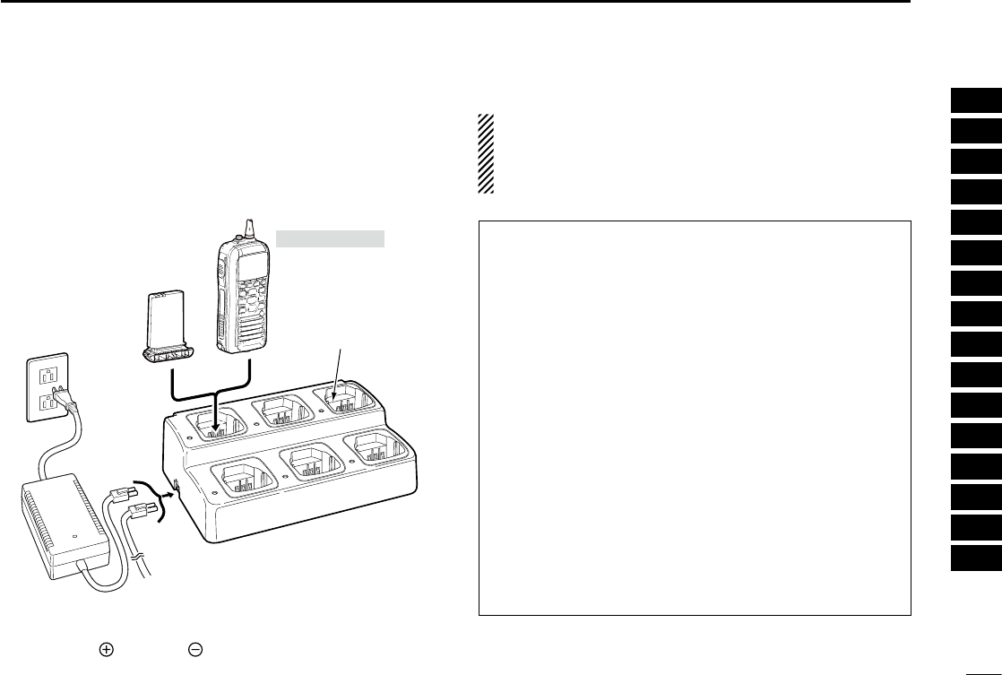
70
10
BATTERY CHARGING
1
2
3
4
5
6
7
8
9
10
11
12
13
14
15
16
Rapid charging with the BC-197+BC-157S D
The optional BC-197 allows up to 6 Li-ion battery packs to be
charged simultaneously. The following items are additionally
required.
•SixBC-157Schargeradapter
•
An optional AC adapter or the DC power cable (OPC-656)
Battery
pack
AD-157S charger
adapters are installed
in each slot.
AC adapter
(Purchased
separately)
Transceiver
DC power cable (OPC-656)
(Connect with the DC power supply; 13.8 V/at least 7 A)
*Abou the OPC-656
Red line : Black line :
Tu rn power OFF
IMPORTANT: Battery charging caution
Ensure the guide tabs on the battery pack are correctly
aligned with the guide rails inside the charger adapter.
(This illustration is described with the BC-160.)

71
12 VHF MARINE CHANNEL LIST
NOTE: Simplex channels, 3, 21, 23, 61, 64, 81, 82 and 83 CANNOT
be lawfully used by the general public in U.S.A. waters.
* Low power only.
Channel number Frequency (MHz)
03 156.150 160.75003
03A 156.150 156.150
156.200 160.80004
02 156.100 160.70002
04A 156.200 156.200
156.250 160.85005
05A 05A 156.250 156.250
06 06 156.300 156.30006
156.350 160.95007
07A 07A 156.350 156.350
08 08 156.400 156.40008
09 09 156.450 156.45009
10 10 156.500 156.50010
11 11 156.550 156.55011
12 12 156.600 156.60012
13* 13*
156.650 156.650
13
14 14
156.700 156.700
14
15* 15*
156.750 156.750
15*
16 16
156.800 156.800
16
17* 17*
156.850 156.850
17
156.900 161.500
18
18A 18A
156.900 156.900
156.950 161.550
19
19A 19A 156.950 156.950
20 20* 157.000 161.60020
20A 157.000 157.000
01A 156.050 156.050
USA
01
156.050 160.65001
CAN
Transmit Receive
INT
Channel number Frequency (MHz)
157.100 161.70022
22A 22A 157.100 157.100
23 157.150 161.75023
21b Rx only 161.650
23A 157.150 157.150
24 24 157.200 161.80024
25 25 157.250 161.85025
25b Rx only 161.850
26 26 157.300 161.90026
27 27 157.350 161.95027
28 28 157.400 162.00028
28b Rx only 162.000
60 156.025 160.62560
156.075 160.67561
61A 61A 156.075 156.075
156.125 160.72562
62A 156.125 156.125
156.175 160.77563
63A 156.175 156.175
64 156.225 160.82564
64A 64A 156.225 156.225
156.275 160.87565
65A 65A 156.275 156.27565A
156.325 160.92566
66A 66A* 156.325 156.32566A
67* 67 156.375 156.37567
21A 21A 157.050 157.050
USA
21 157.050 161.65021
CAN
Transmit Receive
INT
Channel number Frequency (MHz)
71 71 156.575 156.57571
72 72 156.625 156.62572
73 73 156.675 156.67573
70 70 RX only 156.52570
74 74 156.725 156.72574
75* 75* 156.775 156.77575*
76* 76* 156.825 156.82576*
77* 77* 156.875 156.87577
156.925 161.52578
78A 78A 156.925 156.925
156.975 161.57579
79A 79A 156.975 156.975
157.025 161.62580
80A 80A 157.025 157.025
157.075 161.67581
81A 81A 157.075 157.075
157.125 161.72582
82A 82A 157.125 157.125
83 157.175 161.77583
83A 83A 157.175 157.175
83b Rx only 161.775
84 84 157.225 161.82584
84A 157.225 157.225
85 85 157.275 161.87585
85A 157.275 157.275
86 86 157.325 161.92586
69 69 156.475 156.47569
68
USA
68 156.425 156.42568
CAN
Transmit Receive
INT
Channel number Frequency (MHz)
88 88 157.425 162.02588
88A 157.425 157.425
87A 157.375 157.375
87 87 157.375 161.97587
86A
USA
157.325 157.325
CAN
Transmit Receive
INT
Frequency (MHz)
RX only 162.425
RX only 162.450
RX only 162.500
RX only 162.475
RX only 162.525
RX only 161.650
RX only 161.775
RX only 163.275
RX only 162.400
RX only 162.550
Transmit Receive
WX channel
4
5
6
3
7
8
9
10
2
1

72
14
SPECIFICATIONS AND OPTIONS
1
2
3
4
5
6
7
8
9
10
11
12
13
14
15
16
Specifications ■
General D
•Frequencycoverage :Tx156.025–157.425MHz
Rx 156.050–163.275 MHz
•Mode :
FM (16K0G3E),
DSC (16K0G2B)
•Channelspacing : ±25 kHz
•Operatingtemp.range :–20°Cto+60°C
•Currentdrain(at7.4V) :TXhigh 1.5A
(approximately) Max. audio 0.50 A
•Powersupplyrequirement :7.4VDCnorminal
(negative ground)
•Frequencystability :±10PPM(–20°Cto+60°C)
•Antennaimpedance :50˘ nominal
•Dimensions(approximately):
61.2(W) × 141.4(H) × 43.2(D)mm
: 2.4(W)
× 5.6(H) × 1.7(D) inch
(Projections not included)
•Weight (approximately) : 295 g/10.4 oz with BP-275
Transmitter D
•Outputpower :5W/1W
•Modulationsystem :Variablereactancefrequency
modulation
•Max.frequencydeviation :±5.0kHz
•Adjacentchannelpower :70dB
•Spuriousemissions :-68dBc(typical)
Receiver D
•Sensitivity(12dBSINAD) :0.25µV(typical)
•Squelchsensitivity :0.35µVtypical(atthreshold)
•Intermodulationrejectionratio:70dB(typical)
•
Spurious response rejection ratio
:
70 dB (typical)
•Adjacentchannelselectivity :70dB(typical)
•Audiooutputpower :
0.35 W typical at 10% distor-
tion with an 8 ˘ load (External)
: 0.7 W typical at 10% distortion
with an 8 ˘
load (Internal)
All stated specifications are subject to change without notice
or obligation.

73
14SPECIFICATIONS AND OPTIONS
Options ■
•BP-275 Li-ion b at t e r y p a c k
7.4V 1590mAh (Typical) Li-ion battey pack. The battery pack
must be charged with the supplied BC-204 or the optional
BC-205.
•BC-204 r e g u l a r c h a r g e r + BC-147S a c a d a p t e r
Used for regular charging of battery pack. The same as sup-
plied with the transceiver.
•BC-205 r a p i d c h a r g e r + BC-145S a c a d a p t e r + OPC-
515L d C p o w e r c a b l e
For rapid charging of battery pack.
•HM-167 s p e a k e r m i c r o p h o n e
Full sized waterproof speaker-microphone including alliga-
tor type clip to attach to your shirt or collar, etc.
•FA-SC59V a n t e n n a
•CP-25 c i g a r e t t e l i g h t e r c a b l e
For charging the battery pack through a 12 V cigarette light-
er socket. (For BC-204)
•MB-109 b e lt c l i p
•MB-96F l e at h e r b e lt h a n g e r
Approved Icom optional equipment is designed for optimal perfor-
mance when used with an Icom transceiver.
Icom is not responsible for the destruction or damage to an Icom
transceiver in the event the Icom transceiver is used with equipment
that is not manufactured or approved by Icom.

75
1SAFETY TRAINING INFORMATION
Your Icom radio generates RF electromagnetic energy during
transmit mode. This radio is designed for and classified as
“General Population Use” in an uncontrolled environment.
This radio has been evaluated for compliance at the distance
of 2.5 cm (1 inch) with the FCC RF exposure limits for “
Gen-
eral Population Use.
” In addition, your Icom radio complies
with the following Standards and Guidelines with regard to RF
energy and electromagnetic energy levels and evaluation of
such levels for exposure to humans:
•FCCOETBulletin65Edition01-01SupplementC,EvaluatingCompli-
ance with FCC Guidelines for Human Exposure to Radio Frequency
Electromagnetic Fields.
•AmericanNationalStandardsInstitute(C95.1-1992),IEEEStandard
for Safety Levels with Respect to Human Exposure to Radio Frequency
Electromagnetic Fields, 3 kHz to 300 GHz.
•AmericanNationalStandardsInstitute(C95.3-1992),IEEERecom-
mended Practice for the Measurement of Potentially Hazardous Electro-
magnetic Fields– RF and Microwave.
•Thefollowingaccessoriesareauthorizedforusewiththisproduct.Useof
accessories other than those specified may result in RF exposure levels
exceeding the FCC requirements for wireless RF exposure.; Belt Clip
(MB-109), Rechargeable Li-Ion Battery Pack (BP-275).
To ensure that your expose to RF electromagnetic en-
ergy is within the FCC allowable limits for general popu-
lation use, always adhere to the following guidelines:
•DO NOT operate the radio without a proper antenna attached, as this
may damaged the radio and may also cause you to exceed FCC RF ex-
posure limits. A proper antenna is the antenna supplied with this radio by
the manufacturer or antenna specifically authorized by the manufacturer
for use with this radio.
•DO NOT transmit for more than 50% of total radio use time (“50% duty
cycle”). Transmitting more than 50% of the time can cause FCC RF expo-
sure compliance requirements to be exceeded. The radio is transmitting
when the “transmit indicator” appears on the LCD. You can cause the
radio to transmit by pressing the “PTT” switch.
•ALWAYS keep the antenna at least 2.5 cm (1 inch) away from the body
when transmitting and only use the Icom belt clip which is listed on
page 28 when attaching the radio to your belt, etc., to ensure FCC RF
exposure compliance requirements are not exceeded. To provide the re-
cipients of your transmission the best sound quality, hold the antenna at
least 5 cm (2 inches) from your mouth, and slightly off to one side.
The information listed above provides the user with the information needed
to make him or her aware of RF exposure, and what to do to assure that this
radio operates with the FCC RF exposure limits of this radio.
Electromagnetic Interference/Compatibility
During transmissions, your Icom radio generates RF energy that can possibly
cause interference with other devices or systems. To avoid such interference,
turn off the radio in areas where signs are posted to do so. DO NOT operate
the transmitter in areas that are sensitive to electromagnetic radiation such as
hospitals, aircraft, and blasting sites.
WARNING
CAUTION

76
1
SAFETY TRAINING INFORMATION
1
2
3
4
5
6
7
8
9
10
11
12
13
14
15
16
Votre radio Icom produit une énergie électromagnétique
de radiofréquences (RF), en mode de transmission. Elle
est conçue pour une «utilisation grand public», dans un
environnement non contrôlé. Cet appareil a été évalué
et jugé conforme, à 2,5 cm, aux limites d'exposition aux
RF de la FCC, pour une «utilisation grand public». En
outre, votre radio Icom satisfait les normes et directives
qui suivent en matière de niveaux d'énergie et d'énergie
électromagnétique de RF et d'évaluation de tels niveaux en
ce qui concerne l'exposition humaine :
•SupplémentC,édition01-01,duBulletinOETdelaFCC,«Evaluating
Compliance with FCC Guidelines for Human Exposure to Radio Frequency
Electromagnetic Fields».
•Normedel’AmericanNationalStandardsInstitute(ANSI):IEEEC95.1-
1992 sur les niveaux de sécurité compatibles avec l’exposition humaine aux
champs électromagnétiques de radiofréquences (3 kHz à 300 GHz).
•Normedel’ANSI:IEEEC95.3-1992surlaméthoded’évaluation
recommandée du champ magnétique potentiellement dangereux des
radiofréquences et des micro-ondes.
•Lesaccessoiresquisuiventsontapprouvéspouruneutilisationavecce
produit. L'utilisation d'accessoires autres que ceux précisés peut entraîner
des niveaux d'exposition aux RF supérieures aux limites établies par la FCC
en matière d'exposition aux RF sans fil; attache pour ceinture (MB-109),
bloc-piles rechargeable au lithium-ion (BP-275).
CAUTION
Afin de vous assurer que votre exposition à une
énergie électromagnétique de RF se situe dans les
limites permises par la FCC pour une utilisation grand
public, veuillez en tout temps respecter les directives
suivantes :
•NE PAS faire fonctionner la radio sans qu'une antenne appropriée y soit
fixée, car ceci risque d'endommager la radio et causer une exposition
supérieure aux limites établies par la FCC. L'antenne appropriée est celle
qui est fournie avec cette radio par le fabricant ou une antenne spécialement
autorisée par le fabricant pour être utilisée avec cette radio.
• NE PAS émettre pendant plus de 50% du temps total d'utilisation de
l'appareil («50% du facteur d'utilisation»). Émettre pendant plus de 50% du
temps total d'utilisation peut causer une exposition aux RF supérieure aux
limites établies par la FCC. La radio est en train d’émettre lorsque le témoin
du mode de transmission s'affiche sur l'écran ACL. La radio émettra si vous
appuyez sur le bouton du microphone.
• TOUJOURS tenir l'antenne éloignée d'au moins 2,5 cm de votre corps
au moment d'émettre et utiliser uniquement l'attache pour ceinture Icom
illustrée à la p. 28, lorsque vous attachez la radio à votre ceinture, ou à autre
chose, de façon à vous assurer de ne pas provoquer une exposition aux RF
supérieure aux limites fixées par la FCC. Pour offrir à vos interlocuteurs la
meilleure qualité de transmission possible, tenez l'antenne à au moins 5 cm
de votre bouche et légèrement de côté.
Les renseignements ci-dessus fournissent à l'utilisateur toute l'information
nécessaire sur l'exposition aux RF et sur ce qu'il faut faire pour assurer que
cette radio fonctionne en respectant les limites d'exposition aux RF établies
par la FCC.
Interférence électromagnétique et compatibilité
En mode de transmission, votre radio Icom produit de l'énergie de RF qui
peut provoquer des interférences avec d'autres appareils ou systèmes. Pour
éviter de telles interférences, mettez la radio hors tension dans les secteurs
où une signalisation l’exige. NE PAS faire fonctionner l'émetteur dans des
secteurs sensibles au rayonnement électromagnétique tels que les hôpitaux,
les aéronefs et les sites de dynamitage.
AVERTISSEMENT
MISE EN GARDE

MEMO

MEMO

1-1-32 Kamiminami, Hirano-ku, Osaka 547-0003, Japan
A-7005D-1EX
Printed in Japan
© 2012 Icom Inc.
Printed on recycled paper with soy ink.