ICOM orporated 340202 UHF TRANSCEIVER User Manual IC F3161 F4161 Instruction Manual
ICOM Incorporated UHF TRANSCEIVER IC F3161 F4161 Instruction Manual
UserManual.wiki
>
ICOM orporated
>
340202 User Manual
>
User Manual
Contents
1.
User Manual
2.
Updated Manual
User Manual
Navigation menu
Upload a User Manual
Namespaces
Wiki Guide
HTML
PDF
Info
Views
User Manual
Discussion / Help
Navigation
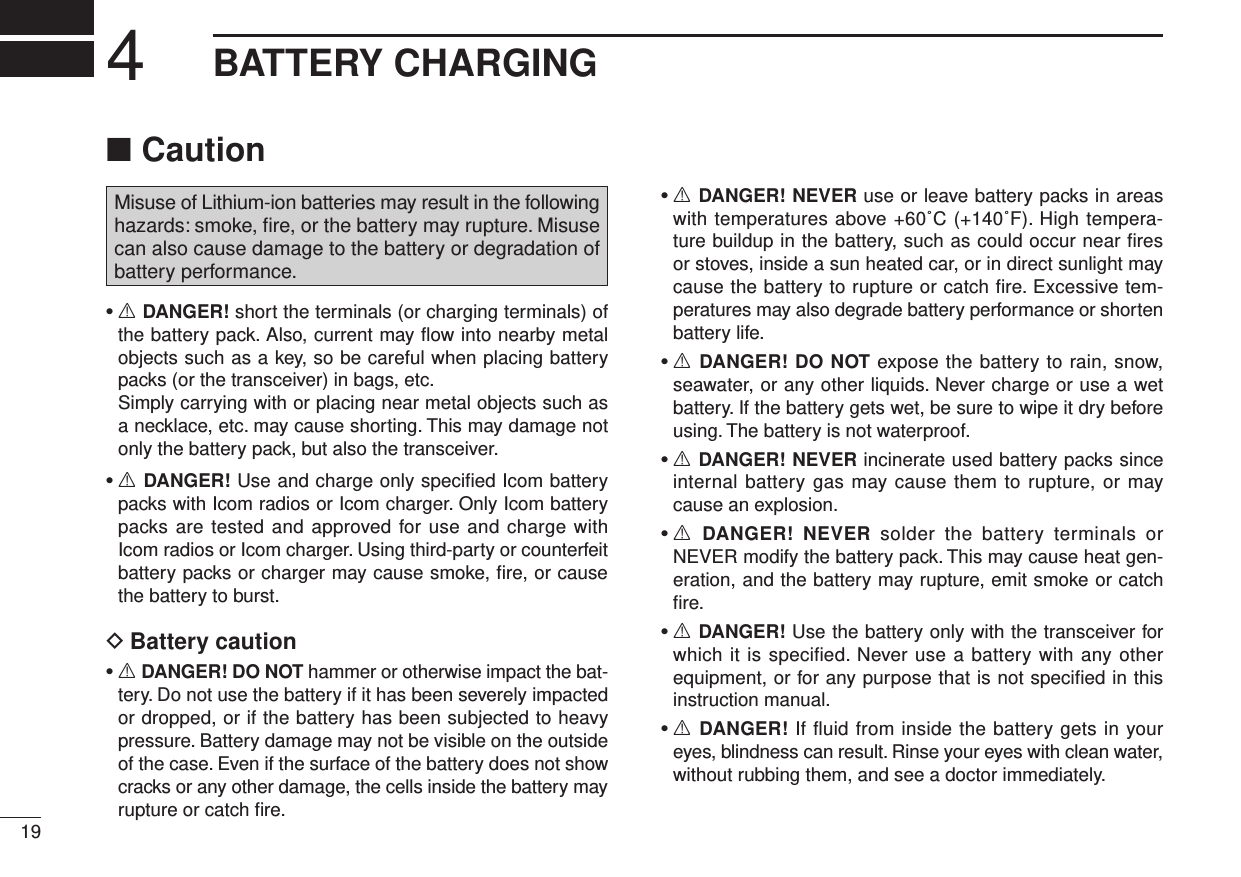
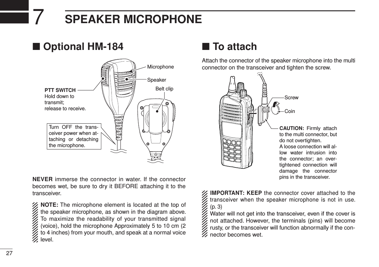
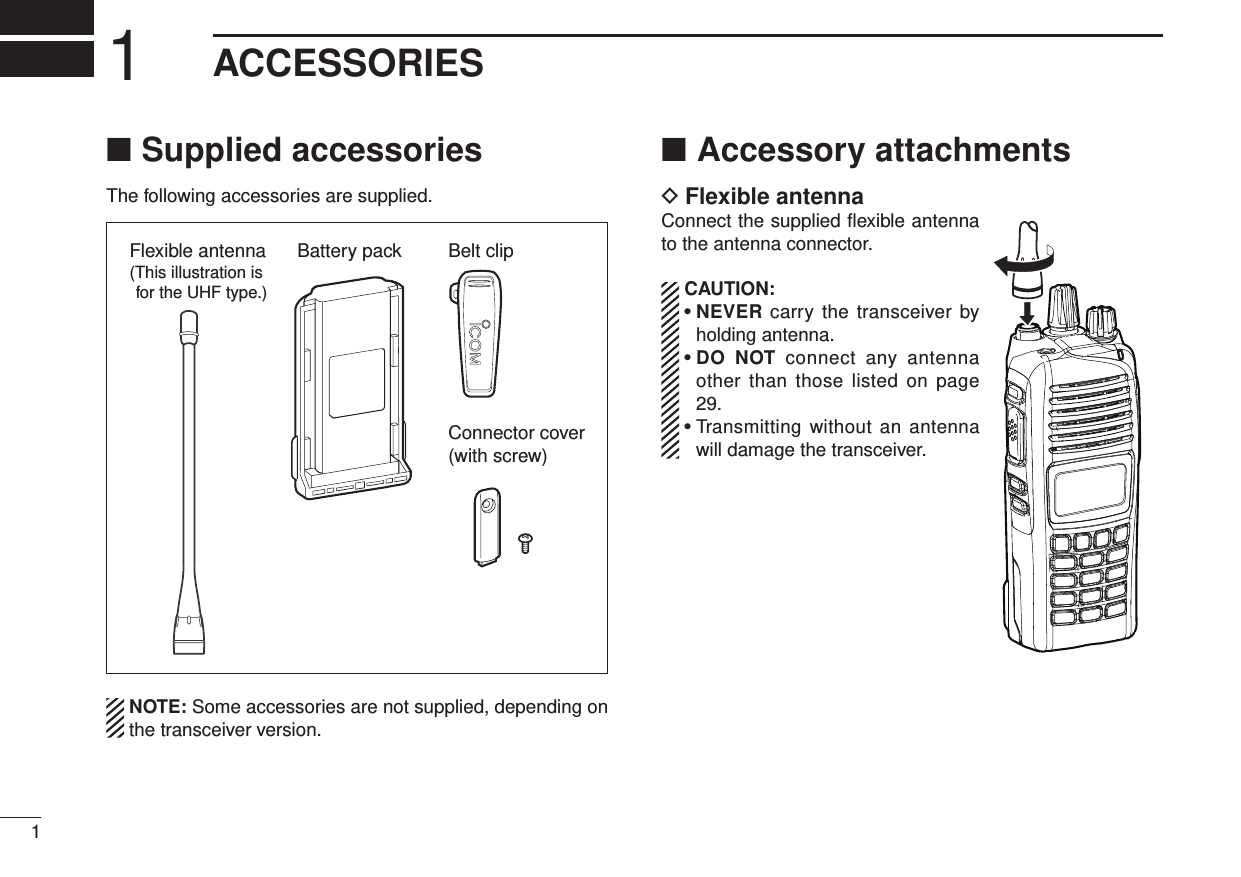
![iiR DANGER! NEVER short the terminals of the battery pack.R DANGER! Use and charge only specified Icom battery packs with Icom radios or Icom chargers. Only Icom battery packs are tested and approved for use with Icom radios or charged with Icom chargers. Using third-party or counterfeit battery packs or chargers may cause smoke, fire, or cause the battery to burst.R WARNING! NEVER hold the transceiver so that the antenna is very close to, or touching exposed parts of the body, especially the face or eyes, while transmitting. The transceiver will perform best if the microphone is 5 to 10 cm (2 to 4 inches) away from the lips and the transceiver is verti-cal.R WARNING! NEVER operate the transceiver with a headset or other audio accessories at high volume levels. Hearing experts advise against continuous high volume op-eration. If you experience a ringing in your ears, reduce the volume level or discontinue use.R WARNING! NEVER operate the transceiver while driving a vehicle. Safe driving requires your full attention—anything less may result in an accident.CAUTION: MAKE SURE the flexible antenna, bat-tery pack and jack cover are securely attached to the trans-ceiver, and that the antenna and battery pack are dry before attachment. Exposing the inside of the transceiver to dust or water will result in serious damage to the transceiver.DO NOT operate the transceiver near unshielded electri-cal blast ing caps or in an explosive atmosphere.DO NOT push [PTT] when not actually intending to transmit.DO NOT use or place the transceiver in direct sunlight or in areas with temperatures below –30°C (–22°F) or above +60°C (+140°F).The basic operations, transmission and reception of the trans-ceiver are guaranteed within the specified operating tempera-ture range. However, the LCD display may not be operate correctly, or show an indication in the case of long hours of operation, or after being placed in extremely cold areas.DO NOT modify the transceiver. The transceiver warranty does not cover any problems caused by unauthorized modification.DO NOT use harsh solvents such as benzine or alcohol when cleaning, as they will damage the transceiver surfaces.BE CAREFUL! The transceiver will become hot when operating it continuously for long periods of time.PRECAUTIONS](https://usermanual.wiki/ICOM-orporated/340202.User-Manual/User-Guide-1710621-Page-3.png)
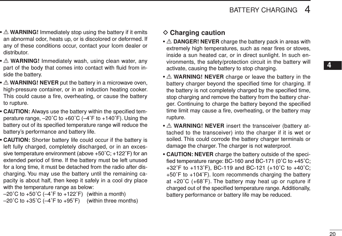
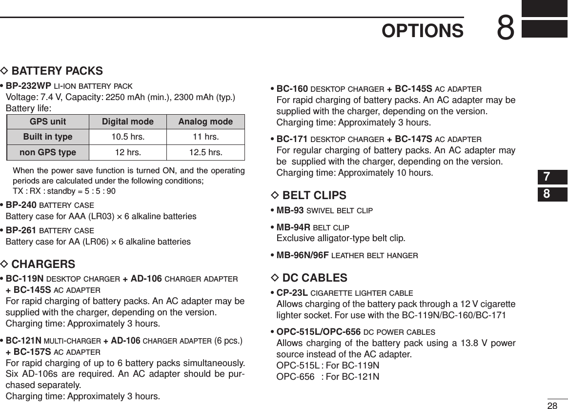
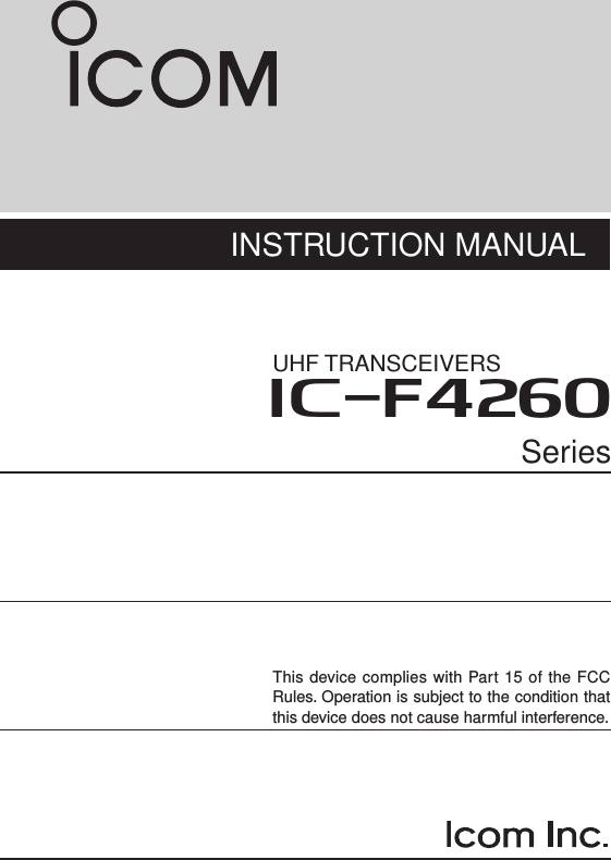
![42PANEL DESCRIPTION12345678910111213141516Front panel ■wetryq!1!0o!2uiMicrophoneSpeakerGPS receiver**A GPS receiver is bult-in, depending on the transceiver version.q ROTARY SELECTORRotate to select the memory channels or the operating zone, depending on the presetting.w ANTENNA CONNECTORConnect the supplied antenna. (p. 1)e DEALER-PROGRAMMABLE KEY [EMR]Desired functions can be preset by your dealer. (p. 6)r DEALER-PROGRAMMABLE KEY [Side1] Desired functions can be preset by your dealer. (p. 6)t PTT SWITCH [PTT]Hold down to transmit, release to receive.y DEALER-PROGRAMMABLE KEYS [Side2]/[Side3]Desired functions can be preset by your dealer. (p. 6)u 10-KEYPAD (Depending on the version)The keypad allows you to enter digits to: • Select memory channels • Select tone channels • Select DTMF codes (during transmit) • Set TX codes • Start up with the passwordi DEALER-PROGRAMMABLE KEYS [P0] to [P3]Desired functions can be preset by your dealer. (p. 6)o FUNCTION DISPLAY (p. 5)Displays a variety of information such as an operating channel number/name, Set mode contents, DTMF code, selected functions and so on.](https://usermanual.wiki/ICOM-orporated/340202.User-Manual/User-Guide-1710621-Page-9.png)
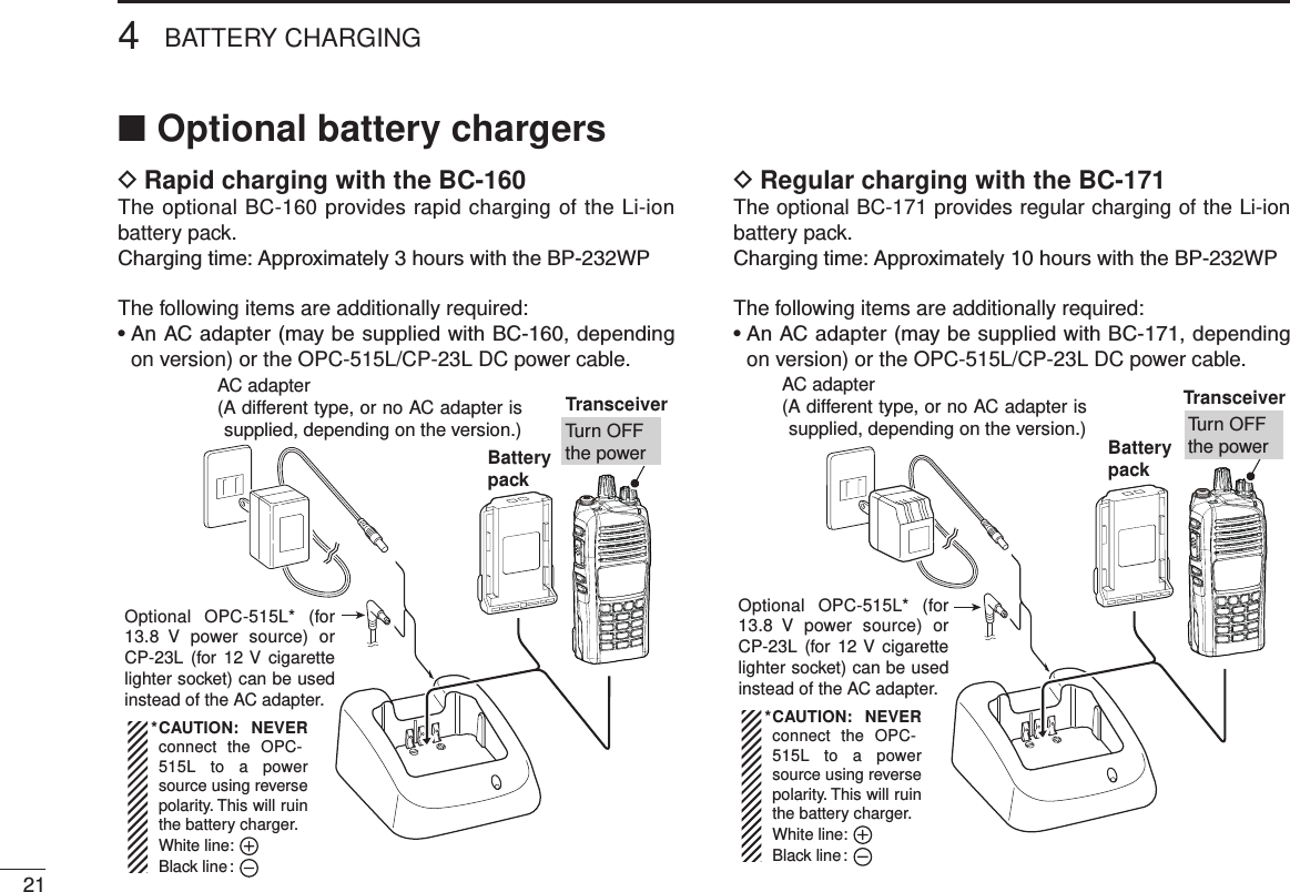
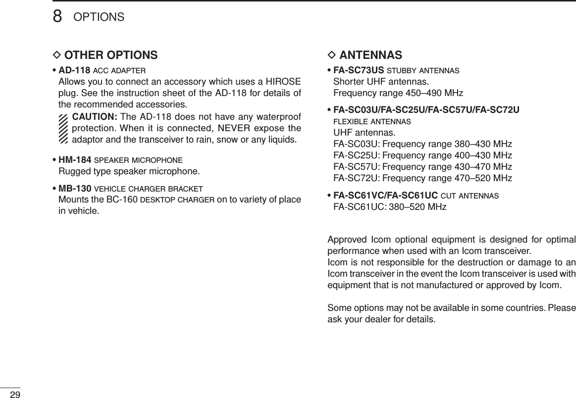
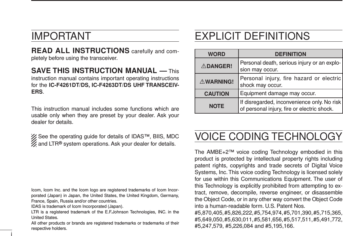
![!0 MULTI-CONNECTORConnects to optional equipment.Connector coverNOTE: Attach the connec-tor cover when optional equipment is not used. See page 3 for details.!1 BUSY/TRANSMIT INDICATOR ➥Lights green while receiving a signal, or when the squelch is open. ➥Lights red while transmitting.!2 VOLUME CONTROL [VOL]Rotate to turn the transceiver power ON or OFF, and ad-just the audio level.Function display ■SETCALA TXCUTXCq t iuyrewo!0q SIGNAL STRENGTH ICON Indicates relative signal strength level.w LOW POWER ICON Appears when low output power is selected. • When the battery power decreases to a specied level, low power is automatically selected.e AUDIBLE ICON ➥ Appears when the channel is in the ‘audible’ (unmute) mode. ➥ Appears when a matched signal is received.r COMPANDER ICON Appears when the compander function is activated.t SCRAMBLER ICON Appears when the voice scrambler function is activated.52PANEL DESCRIPTION](https://usermanual.wiki/ICOM-orporated/340202.User-Manual/User-Guide-1710621-Page-10.png)
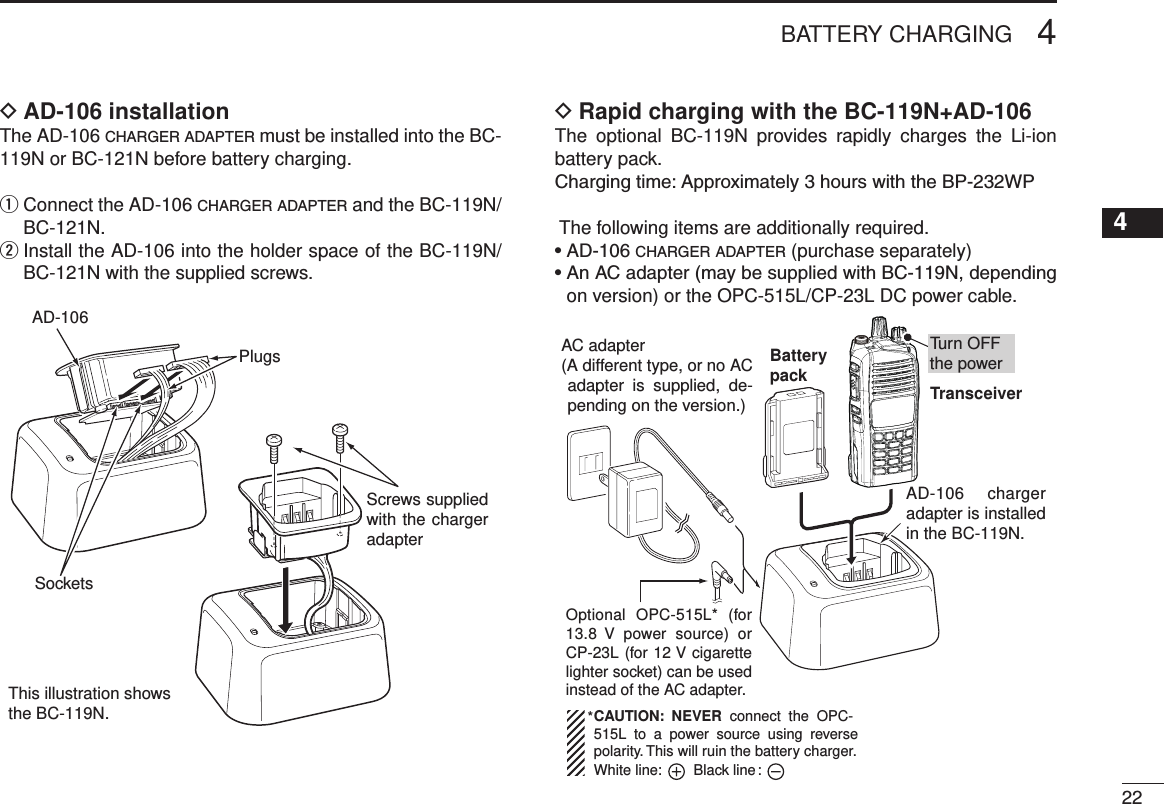
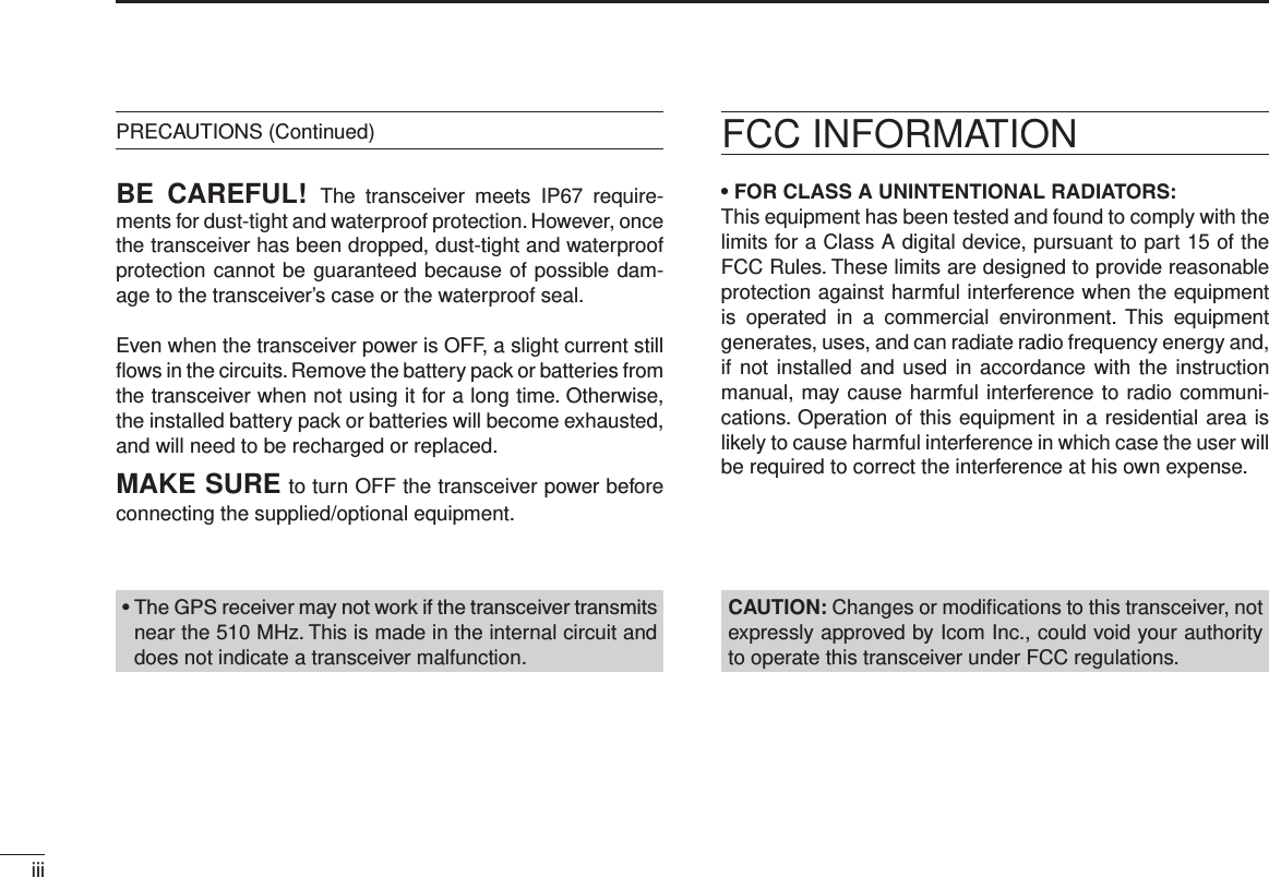
![62PANEL DESCRIPTION12345678910111213141516y BELL ICON Appears or blinks when a matched signal is received, de-pending on the presetting.u CALL CODE MEMORY ICON Appears when the call code memory is selected.i BATTERY ICON Appears or blinks when the battery power decreases to a specified level.IndicationFull Mid Chargingrequired ExhaustedBatteryBattery levelblinks when the battery is exhausted.blinks when the battery is over charged.o ALPHANUMERIC DISPLAY ➥ Displays the operating channel number, channel name, Set mode contents, DTMF code, and so on. ➥ The display mode can be set to one line or two lines. Ask your dealer for details. • In this instruction manual, the LCD illustration is described using the two-line display mode.!0 KEY ICONS Indicates the programmed function of the front panel keys ([P0], [P1], [P2] and [P3]).Programmable function keys ■The following functions can be assigned to the [EMR], [Side1], [Side2], [Side3], [P0], [P1], [P2] and [P3] program-mable function keys. Consult your Icom dealer or system operator for details con-cerning your transceivers programming.If the programmable function names are bracketed in the fol-lowing explanations, the specific key is used to activate the function according to the presetting.CH UP AND DOWN KEYS “UP” “DOWN”➥ Push to select an operating channel. When [Rotary selec-tor] selects “operating channel,” this key is disabled.➥ Push to select a transmit code channel after pushing [TX Code CH Select].➥ Push to select a DTMF channel after pushing [DTMF Au-todial].➥ Push to select a scan group after holding down [Scan].➥ Push to select the desired application type, individual/talk-group ID, TX status message and SDM (Short Data Mes-sage) after pushing [Digital Button].](https://usermanual.wiki/ICOM-orporated/340202.User-Manual/User-Guide-1710621-Page-11.png)
![2PANEL DESCRIPTIONZONE KEY “ZONE”Push this key, then push [CH Up] or [CH Down] to select the desired zone. When [Rotary selector] selects the “operating zone,” this key operation is disabled. What is a “zone”?— Selected channels are assigned to a zone according to how they are to be used in a group. For example, ‘Staff A’ and ‘Staff B’ are assigned to a “Busi-ness” zone, and ‘John’ and ‘Cindy’ are assigned to a “Pri-vate” zone.ZONE UP AND DOWN KEYS “ZNUP” “ZNDN”Push to select an operating zone. When [Rotary selector] se-lects an “operating zone,” these keys are disabled.SCAN KEY “SCAN”➥ Push to start or cancel a scan. • When the Power ON Scan function is activated, push to pause the scan. The paused scan resumes after the specified time pe-riod has passed.➥ Hold down this key for 1 second to display the scan group, then push [CH Up] or [CH Down] to select the desired group.SCAN ADD/DEL (TAG) KEY “SCAD”➥ Push to add a channel to, or delete it from the current scan group. 1. Push to display the scan group, then push [CH Up] or [CH Down] to select the desired group. 2. Push to add a channel to, or delete it from the selected group. 3. Hold down for 1 second to exit the scan group selection mode.➥ While a scan is paused on a non-priority channel, push this key to delete the selected channel from the scan group. Depending on the presetting, the cleared channel may be added to the scan group again after the scan is can-celled. (Nuisance Delete function)PRIORITY CHANNEL KEYS “PRA” “PRB”➥ Push to select the Priority A or Priority B channel.PRIORITY CHANNEL (REWRITE) KEYS “PRAR” “PRBR”➥ Push to select the Priority A or Priority B channel.➥ Hold down [Prio A (Rewrite)] or [Prio B (Rewrite)] for 1 second to rewrite the Priority A or Priority B channel as the operating channel.7](https://usermanual.wiki/ICOM-orporated/340202.User-Manual/User-Guide-1710621-Page-12.png)
![82PANEL DESCRIPTIONMEMORY CH 1/2/3/4 KEYS “CH1” “CH2” “CH3” “CH4”Push to directly select memory channels 1 to 4.MONI KEY “MON”➥ Push to mute and release the CTCSS (DTCS) or 2-tone squelch mute. Open any squelch or deactivate any mute while holding down this key. (LMR operation only)➥ Independently activates one or two of the following func-tions on each channel. (PMR operation only) • Hold down to unmute the channel (audio is heard; ‘Audible’ mode). • Push to mute the channel (sets to ‘Inaudible’ only). • Push after the communication is nished to send a ‘reset code’. (5-tone/BIIS operation only) NOTE: The unmute mode (‘Audible’ mode) may auto-matically return to the mute mode (‘Inaudible‘ mode) after a specified period.LIGHT KEY “LIGT”Push to temporarily turn ON the transceiver’s backlight, only when the backlight function is turned OFF in the User set mode. LOCK KEY “LOCK”➥ Hold down for 1 second to electronically lock all program-mable keys to prevent accidental frequency changes and unnecessary function access, except the following: [PTT], [Call] (incl. Call A and Call B), [Moni(Audi)], [Light], [Emergency], [Surveillance], [Lone Worker] and [OPT 1/2/3].➥ Hold down for 1 second again to turn the lock function OFF.LONE WORKER KEY “LONE”Push to turn the Lone Worker function ON or OFF.• If the Lone Worker function is activated, the Emergency function is automatically turned ON after the specified time period has passed with no operation performed.HIGH/LOW KEY “H/L” Push to select the transmit output power temporarily or per-manently, depending on the presetting.• Ask your dealer for the output power level for each selection.TONE/RAN CH SELECT KEY “T SEL”➥ While in the analog mode, push to enter the continuous tone channel selection mode. Then select the desired tone frequency/code setting using [CH Up] or [CH Down]. After the selection, push this key again to set the tone/code.➥ While in the digital mode, push to enter the RAN channel selection mode. Then select the desired RAN setting using [CH Up] or [CH Down]. After the selection, push this key again to set the RAN.➥ While in the mixed (digital and analog) mode, push to enter the continuous tone channel selection mode. Then select the desired tone frequency/code setting using [CH Up] or [CH Down]. After the selection, push this key to set the tone/code. After that, the RAN channel selection screen appears. Select the desired RAN setting using [CH Up] or [CH Down]. After the selection, push this key again to set the RAN.12345678910111213141516](https://usermanual.wiki/ICOM-orporated/340202.User-Manual/User-Guide-1710621-Page-13.png)
![2PANEL DESCRIPTIONC.TONE CH ENT KEY “TSEL”Push to enter the continuous tone channel selection mode. Then select the desired tone frequency/code setting using [CH Up]/[CH Down]. The selected channel remains set as a continuous tone channel until another channel is designated as such.TALK AROUND KEY “TA”Push to turn the talk around function ON or OFF.• The talk around function equalizes the transmit frequency to the receive frequency for transceiver-to-transceiver communication.WIDE/NARROW KEY “W/N”Push to toggle the IF bandwidth between wide and narrow.DTMF AUTODIAL KEY “DTMA”Push to enter the DTMF channel selection mode. Then select the desired DTMF channel using [CH Up]/[CH Down]. After selecting the DTMF channel, push again to transmit the selected DTMF code.RE-DIAL KEY “DTMR”Push to transmit the last-transmitted DTMF code.CALL KEYS “CALL” “CALA” “CALB”Push to transmit a 2/5-tone or BIIS ID code.• A Call transmission may be necessary before you call another sta-tion, depending on your signaling system.• [Call A] and/or [Call B] may be selectable when your system employs selective ‘Individual/Group’ calls. Ask your dealer which call is assigned to each key.EMERGENCY KEY “EMR”Hold down to transmit an emergency call.• The emergency call transmits and beep sounds. The display does not change.• The transceiver can transmit the emergency call silently, or with the display changing, depending on the presetting. Ask your dealer for details.• If you want to cancel the emergency call, hold down the key again before transmitting it.• The emergency call is transmitted only one time, or repeatedly until receiving a control code, depending on the presetting.SURVEILLANCE KEY “SURV”Push to turn the surveillance function ON or OFF.When this function is turned ON, a beep is not heard and the LCD backlight does not light when a signal is received or a key is pushed.TX CODE ENTER KEYS “TXCE”Push to directly enter the ID code edit mode, for both 5-tone and MSK. Then set the desired digit using [CH Up]/[CH Down]. (p. 15)9](https://usermanual.wiki/ICOM-orporated/340202.User-Manual/User-Guide-1710621-Page-14.png)
![102PANEL DESCRIPTIONTX CODE CHANNEL SELECT KEY “TXC”Push to enter the TX code channel selection mode. Then set the desired channel using [CH Up]/[CH Down]. (pp. 14, 15)TX CODE CHANNEL UP/DOWN KEYS “TXCU” “TXCD”Push to select a TX code channel directly.ID-MEMORY SELECT KEY “IDMS”➥ Recalls detected ID codes. • Push this key, then select the ID code using [CH Up]/[CH Down]. • Up to ve ID’s can be memorized.➥ Hold down for 1 second to erase the selected ID’s.SCRAMBLER/ENCRYPTION KEY “SCR”➥ While in the analog mode operation, push to toggle the voice scrambler function ON or OFF.➥ While in the digital mode operation, push to toggle the encryption transmission function ON or OFF.COMPANDER KEY “COMP”Push to toggle the compander function ON or OFF. The compander function reduces noise components from the transmitting audio to provide clear communication.USER SET MODE KEY “SET”➥ Hold down for 1 second to enter the User set mode. • While in the User set mode, push this key to select an item, and change the value or condition using [CH Up]/[CH Down].➥ Hold down this key for 1 second again to exit the User set mode.The User set mode can also be entered through the ‘Power ON function.’ Refer to page 16.OPT OUT KEYS “OP1” “OP2” “OP3”Push to control the output signal level from the optional unit connector.OPT MOMENTARY KEYS “O1M” “O2M” “O3M”Push to control the output signal level from the optional unit connector.12345678910111213141516](https://usermanual.wiki/ICOM-orporated/340202.User-Manual/User-Guide-1710621-Page-15.png)
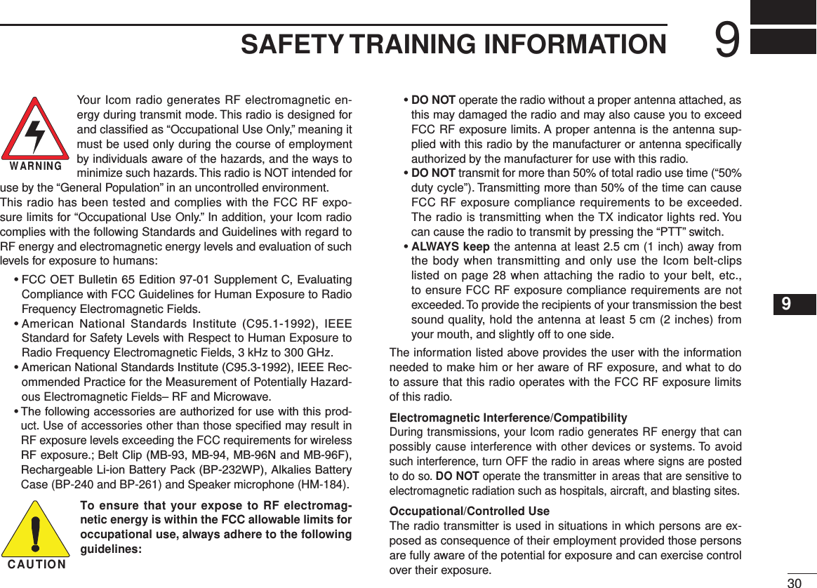
![Turning power ON ■ Prior to using the transceiver for the first time, the battery pack must be fully charged for optimum life and operation. (p. 21)q Rotate [VOL] to turn ON the power.w If the transceiver is programmed for a start up password, input the digit codes as directed by your dealer. • The 10-keypad can be used for password input, depending on the transceiver version. • The keys in the table below can be used for password input. • The transceiver detects numbers in the same block as identical. Therefore “01234” and “56789” are the same.KEYNUMBER 0549382716(Side1)P0 P1 P2 P3e If the “PASSWORD” indication does not clear after input-ting 6 digits, the input code number may be incorrect. Turn OFF the power and start over.Battery type selection DWhen turning ON the transceiver, the battery type must be selected according to the attached battery type. Turn OFF the power. q While holding down [EMR] and [PTT], turn ON the power wwith rotating [VOL] to toggle the attaching battery type. • After the display appears, release [EMR] and [PTT]. • “ DRY BATT” is displayed for about 3 seconds, then the low power icon “Lo” appears when the battery case is selected. The trans-mit output power is automatically set to low1. • “LI-ION” is displayed for about 3 seconds when the Lithium-ion battery pack is selected.• This operation may not be available, depending on the presetting. Ask your dealer for details.3BASIC OPERATION11](https://usermanual.wiki/ICOM-orporated/340202.User-Manual/User-Guide-1710621-Page-16.png)
![123BASIC OPERATIONChannel selection ■Several types of channel selections are available. Methods may differ, depending on the presetting.NON-ZONE TYPE:To select the desired operating channel:• Push [CH Up] or [CH Down].• Rotate [ROTARY SELECTOR]*. - Up to 16 preprogrammed channels can be selected.• Push one of [MR-CH 1] to [MR-CH 4]. ZONE TYPE:To select the desired zone:• Push [Zone], then push [CH Up] or [CH Down].• Push [Zone Up] or [Zone Down].• Rotate [ROTARY SELECTOR]*. - Up to 16 preprogrammed zones can be selected.D Voting operationThe transceiver automatically starts scanning when a zone, specified for the voting operation, is selected.The voting scan detects the signal of the repeater and auto-matically selects the strongest station.AUTOMATIC SCAN TYPE:Channel setting is not necessary for this type. When you turn ON power, the transceiver automatically starts scanning. Scanning stops when a call is received.* Depending on the presetting. When [Rotary selector] selects “Operating channel,” [CH Up]/[CH Down] are disabled. When [Rotary selector] selects “Operating zone,” [Zone]/[Zone Up]/ [Zone Down] are disabled.12345678910111213141516](https://usermanual.wiki/ICOM-orporated/340202.User-Manual/User-Guide-1710621-Page-17.png)
![Call procedure ■When your system employs tone signaling, excluding CTCSS and DTCS, this call procedure may be necessary prior to voice transmission. The tone signaling employed may be a selective calling system which allows you to call only specific station(s) and prevents unwanted stations from contacting you.q Select the desired TX code channel or 2/5-tone code ac-cording to your System operator’s instructions. • This may not be necessary, depending on the presetting. • Refer to pages 14 or 15 for selection.w Push [Call], assigned to one of the dealer programmable keys.e After transmitting, the remainder of your communication can be carried out in the normal way.Selective calling Non-selective calling■ Receiving and transmitting CAUTION: Transmitting without an antenna will damage the transceiver. Receiving:q Rotate [VOL] to turn ON the power.w Push [CH Up] or [CH Down], or rotate [ROTARY SELEC-TOR], depending on the presetting, to sequentially select the conventional system channel.e When receiving a call, adjust the audio output level to a comfortable listening level.NOTE: When a matched RX code signal is received, audio from the microphone may be automatically transmitted for a specied time period.** Depending on the presetting. Ask your dealer for details.Transmitting:Wait for the channel to become clear to avoid interference.q While holding down [PTT], speak into the microphone at a normal voice level. • When a tone signaling system is used, the call procedure de-scribed on the previous page may be necessary.w Release [PTT] to receive. IMPORTANT: To maximize the audio quality of your sig-nal: 1. Pause briefly after pushing [PTT]. 2. Hold the microphone 5 to 10 cm (2 to 4 inches) from your mouth, then speak at a normal voice level.3BASIC OPERATION13](https://usermanual.wiki/ICOM-orporated/340202.User-Manual/User-Guide-1710621-Page-18.png)
![143BASIC OPERATIONTransmitting notes D• Transmit inhibit function The transceiver has several inhibit functions which restrict transmission under the following conditions:- The channel is muted (‘Inaudible’ mode; “ ” (Audible icon) does not appear.)- The channel is busy.- Unmatched or matched CTCSS is received, depending on the presetting.- The selected channel is a ‘receive only’ channel.• Time-out timer After continuous transmission for a preset time period, the time-out timer causes the transceiver to stop transmitting.• Penalty timer Once transmission is cut OFF, it is further inhibited for a period determined by the Penalty timer.TX code channel selection DIf the transceiver has [TX Code CH Select] assigned to it, the display can be toggled between the operating channel number or name, and the TX code channel number or name. When the TX code channel number, or name is displayed, pushing [CH Up] or [CH Down] selects the TX code channel.USING [TX CODE CH SELECT] KEY: q Push [TX Code CH Select]— a TX code channel number or name appears.w Push [CH Up] or [CH Down] to select the desired TX code channel.e After selecting, push [TX Code CH Select] to set the code. • Return to the standby mode.r Push [Call] to transmit the selected TX code.USING [TX CODE CH UP]/[TX CODE CH DOWN] KEY:If the transceiver has a [TX Code CH Up] or [TX Code CH Down] key assigned, the preset TX code channel can be di-rectly selected when pushed.☞ Continued on the next page12345678910111213141516](https://usermanual.wiki/ICOM-orporated/340202.User-Manual/User-Guide-1710621-Page-19.png)
![3BASIC OPERATIONTX code number edit D (PMR operation only)If the transceiver has [TX Code CH Select] or [TX Code Enter] assigned, the TX code contents can be edited within the allowable digits.USING [TX CODE CH SELECT] KEY:q Push [TX Code CH Select] to enter the TX code channel selection mode. • Select the desired operating channel before entering the TX code channel selection mode, if necessary.w Push [TX Code CH Select] for 1 second to enter the TX code edit mode. • The digit to be edited blinks.e Push [TX Code CH Select] to select the desired digit to be edited.r Push [CH Up]/[CH Down] to select the desired digit.t Push [TX Code CH Select] to set it. The digit to the right will automatically blink.y Repeat r and t to edit all allowable digits.u After editing, push [TX Code CH Select] to set the code. • Return to the standby mode.i Push [Call] to transmit.USING [TX CODE ENTER] KEY:q After pushing [TX Code CH Select], push [CH Up] or [CH Down], or push [TX Code CH Up] or [TX Code CH Down] to select the desired TX code channel.w Push [TX Code Enter] to enter the TX code edit mode. • The digit to be edited blinks.e Push [TX Code Enter] to select the desired digit to be ed-ited.r Push [CH Up]/[CH Down] to select the desired digit.t Push [TX Code Enter] to set. The digit to the right will au-tomatically blink.y Repeat r and t to edit all allowable digits.u After editing, push [TX Code Enter] to set. • Return to the standby mode.i Push [Call] to transmit.DTMF transmission DIf the transceiver has [DTMF Autodial] assigned, the au-tomatic DTMF transmission function can be used. Up to 8 DTMF channels are selectable.q Push [DTMF Autodial]— a DTMF channel appears.w Push [CH Up] or [CH Down] to select the desired DTMF channel.e Push [DTMF Autodial] to transmit the DTMF code on the selected DTMF channel.15](https://usermanual.wiki/ICOM-orporated/340202.User-Manual/User-Guide-1710621-Page-20.png)
![163BASIC OPERATIONUser set mode ■The User set mode is accessed at power ON, and allows you to set seldom-changed settings and “customize” the trans-ceiver operation to suit your preferences and operating style.Entering the User set mode:q While holding down [P1] and [P2], rotate [VOL] to turn ON the power. • “SET MODE” appears for 1 second at power ON.w Hold down [P0] to enter the User set mode. e Push [P0] several times to select the appropriate item. Then push [Side2] or [Side3] to set the desired level or op-tion. • Available set mode functions are Backlight, LCD contrast, Beep, Beep Level, Ringer Level, SQL Level, AF Min Level, Mic Gain, VOX Gain*, VOX Delay*, Battery Voltage, Signal Moni, Lone Worker and System Info. * Appears only when the external VOX unit is connected.r Hold down [P0] again to exit the User set mode.The User set mode is also selectable with a programmable key. Please refer to page 10 [User Set Mode] section for in-structions on using the key assigned to the User set mode.[User Set Mode] allows for quick item selection. Set “Enable” for the often used items in the CS-F3160/F5060 c l o n i n g s o f t w a r e . Ask your dealer for details. NOTE: [Side2] or [Side3] and [P0] activate while in the User set mode, regardless of the assigned key functions.Scrambler function ■The voice scrambler function provides private communica-tion between stations. All transceiver versions have a built-in frequency inversion type scrambler.➥ Push [Scrambler] to toggle the scrambler function ON or OFF. • “ ” (Scrambler icon) appears when the function is ON.Stun function ■When the specied ID, set as a stun ID or kill ID, is received, the stun function is activated.When a stun ID is received, the transceiver becomes unus-able. Entering the password (p. 11) or receiving a revive ID, is necessary to operate the transceiver again.When a kill ID is received, the transceiver switches to the cloning required condition. Cloning the transceiver is neces-sary to operate the transceiver again.12345678910111213141516](https://usermanual.wiki/ICOM-orporated/340202.User-Manual/User-Guide-1710621-Page-21.png)
![173BASIC OPERATIONEmergency transmission ■When [Emergency] is pushed for the specied time period, an emergency signal is transmitted once, or repeatedly, on the specified emergency channel, depending on the presetting.A repeat emergency signal is automatically transmitted until the transceiver receives an acknowledgement signal, or you turn OFF the transceiver power.When no emergency channel is specied, the signal is trans-mitted on the previously selected channel.If you want to cancel the emergency call, hold down [Emer-gency] again before transmitting it.If your transceiver is preset for Silent operation, you can transmit an Emergency call without the beep sounding and the LED indicator lighting.IMPORTANT: It is recommended to set a separate emer-gency channel to provide reliable emergency calls.NOTES DDepending on the presetting, the following functions may be automatically activated. Ask your dealer for details.• Auto TX functionAfter the emergency call transmission, audio from the micro-phone is automatically transmitted for a specified time pe-riod.• Auto RX functionAfter the emergency call transmission, the transceiver stands by in the audible mode for the specified time period.Man Down Emergency Call ■This function is available, depending on the transceiver version. When the transceiver has been left in a horizontal position for the specied time period*, the transceiver enters the emer-gency mode, and then the countdown starts.After the specied time period* has passed, an emergency call is automatically transmitted once, or repeatedly.If the transceiver is placed in a vertical position before the first transmission, the transceiver exits the emergency mode and the emergency call is cancelled.IMPORTANT: It is recommended to set a separate emer-gency channel to provide reliable emergency calls.](https://usermanual.wiki/ICOM-orporated/340202.User-Manual/User-Guide-1710621-Page-22.png)
![183BASIC OPERATION12345678910111213141516Automatic Key Lock function ■When [Lock] is assigned to any key, and the Automatic Key Lock timer is preprogrammed*, the key lock function can be automatically turned ON after the specified time period has passed with no key operation.While the lock function is ON, hold down [Lock] for 1 second to turn the function OFF.*When “0” is programmed, this function is disabled.Priority A channel selection ■When one of the following operations is performed, the trans-ceiver automatically selects the Priority A channel.• Turning the power ON The Priority A channel is selected each time the trans-ceiver power is turned ON.• Status call The Priority A channel is selected when transmitting a status call. (BIIS operation only)• Clear down The Priority A channel is selected after the clear down signal is transmitted.](https://usermanual.wiki/ICOM-orporated/340202.User-Manual/User-Guide-1710621-Page-23.png)