ICOM orporated 350000 HF Transeiver User Manual
ICOM Incorporated HF Transeiver
UserManual.wiki
>
ICOM orporated
>
350000 User Manual
User Manual
Navigation menu
Upload a User Manual
Namespaces
Wiki Guide
HTML
PDF
Info
Views
User Manual
Discussion / Help
Navigation
![v2001 NEW 2001 NEWPRECAUTIONSR DANGER HIGH RF VOLTAGE! NEVER attach an antenna or internal antenna connector during trans-mission. This may result in an electrical shock or burn.R WARNING! NEVER operate the transceiver with a headset or other audio accessories at high volume levels. Hearing experts advise against continuous high volume operation. If you experience a ringing in your ears, reduce the volume or discontinue use.R WARNING! NEVER operate or touch the trans-ceiver with wet hands. This may result in an electric shock or damage to the transceiver.R WARNING! NEVER apply AC power to the [DC13.8V] socket on the transceiver rear panel. This could cause a fire or damage the transceiver.R WARNING! NEVER apply more than 16 V DC to the [DC13.8V] socket on the transceiver rear panel, or use reverse polarity. This could cause a fire or damage the transceiver.R WARNING! NEVER let metal, wire or other objects protrude into the transceiver or into connectors on the rear panel. This may result in an electric shock.R WARNING! ALWAYS use the supplied Black and red cables with fuse holders. After connecting the fuse holders, NEVER cut the DC power cable between the DC plug and fuse holder. If an incorrect connection is made after cutting, the transceiver might be damaged.R WARNING! Immediately turn OFF the transceiver power and remove the power cable if it emits an abnor-mal odor, sound or smoke. Contact your Icom dealer or distributor for advice.CAUTION: NEVER change the internal settings of the transceiver. This may reduce transceiver performance and/or damage to the transceiver.In particular, incorrect settings for transmitter circuits, such as output power, idling current, and so on, might damage the expensive final devices.The transceiver warranty does not cover any problems caused by unauthorized internal adjustment.CAUTION: NEVER install the transceiver in a place without adequate ventilation. Heat dissipation may be reduced, and the transceiver may be damaged.DO NOT use or place the transceiver in direct sunlight or in areas with temperatures below –30°C (–22°F) or above +60°C (+140°F).The basic operations, transmission and reception of the transceiver are guaranteed within the specified operat-ing temperature range. However, the LCD display may not be operate correctly, or show an indication in the case of long hours of operation, or after being placed in extremely cold areas.DO NOT use harsh solvents such as benzine or alco-hol when cleaning, as they will damage the transceiver surfaces.DO NOT push the PTT switch when you don’t actually desire to transmit.DO NOT place the transceiver against walls or putting anything on top of the transceiver. This may overheat the transceiver.Always place unit in a secure place to avoid inadvertent use by children.BE CAREFUL! If you use a linear amplifier, set the transceiver’s RF output power to less than the linear amplifier’s maximum input level, otherwise, the linear amplifier will be damaged.BE CAREFUL! The transceiver will become hot when operating the transceiver continuously for long periods of time.USE only the specified microphone. Other manufactur-ers’ microphones have different pin assignments, and connection to the IC-F8101 may damage the transceiver or microphone.During mobile operation, NEVER place the transceiver where air bag deployment may be obstructed.During mobile operation, DO NOT place the transceiver where hot or cold air blows directly onto it.During mobile operation, DO NOT operate the trans-ceiver without running the vehicle’s engine. When the transceiver’s power is ON and your vehicle’s engine is OFF, the vehicle’s battery will soon become exhausted.Make sure the transceiver power is OFF before starting the vehicle engine. This will avoid possible damage to the transceiver by ignition voltage spikes.During maritime mobile operation, keep the trans-ceiver and microphone as far away as possible from the magnetic navigation compass to prevent erroneous indi-cations.Turn OFF the transceiver’s power and/or disconnect the DC power cable when you will not use the transceiver for long period of time.KEEP the transceiver away from the heavy rain, and Never immerse it in the water. The transceiver meets IP54* requirements for dust-protection and splash resis-tance.However, once the transceiver has been dropped, dust-protection and splash resistance cannot be guaranteed due to the fact that the transceiver may be cracked, or the waterproof seal damaged, and so on.* Only when the supplied microphone is attached.](https://usermanual.wiki/ICOM-orporated/350000/User-Guide-1993755-Page-6.png)
![11PANEL DESCRIPTION2001 NEW1234567891011121314151617Quick Referenceq VOLUME KEYS [ +]/[ –] (p. 8)Adjusts the audio output level.w EMERGENCY KEY [ ] NOTE: While in the VFO mode, the Emergency key cannot be used.➥ Push to enter the Emergency channel list. • Push again to return to the normal operating screen.➥ Hold down for 1 second to transmit Selcall and RFDS (Royal Flying Doctor Service) calls to the specified Selcall addresses in sequential order. NOTE: RFDS calls are available in only the Australian versions.e POWER KEY [ ] ➥ When the transceiver’s power is OFF: Push to turn ON the transceiver power. • First, turn ON the DC power source. ➥ When the transceiver’s power is ON: Hold down for 2 seconds to turn OFF the power.r CALL KEY [ ]Push to enter the Call menu. • Push again to go to the next screen in the Call menu.t UP/DOWN KEYS [r]/[s]Selects the operating channel, the items in the Menu mode, and so on.y ENTER KEY [4] Push to enter and exit the selected Menu in the ➥Menu screen. Hold down for 1 second to enter the program- ➥ming mode.u CLEAR KEY [8] Push to enter or exit the Main Menu screen. ➥ Push to return to the previous screen. ➥i CALL END/SCAN [ ] Push to hang up or terminate a call. ➥Push to start or stop a scan ➥o FUNCTION KEYS [§]/[§§]/[§§§] Push to select the function that is displayed above each key on the LCD display. • The functions vary, depending on the preprogramming and selected menu.q ww !1eerio!0tyuKeypad (p. 2)qouytri• HM-192• Front panel■ Controller (Front panel or HM-192)•CommonContinued on the next page.](https://usermanual.wiki/ICOM-orporated/350000/User-Guide-1993755-Page-7.png)
![21PANEL DESCRIPTION2001 NEW 2001 NEW!0 MICROPHONE CONNECTOR [MIC]Connects to only the microphone supplied with the transceiver. NOTE: NEVER connect the HM-192 or any other microphone here. This could damage the trans-ceiver and/or the microphone.yutrqweiFront view q MIC (microphone input)w MIC SW1e AFr MIC SW2t PTTy GNDu GND (microphone ground)i +8 V DC output (Max 10 mA)!1 LOCK KEY [ ]Hold down for 1 second to set the Key lock function to ALL, NUMERIC KEY or OFF.D Keypad➥ Inputs numbers, characters or letters.10-key•Frontpanel •HM-192•SelectablecharactersKEY INPUT INPUTKEY(space)Upper/Lower case letters/Numbers1 Q Z q z2 A B C a b c3 D E F d e f4 G H I g h i5 J K L j k l6 M N O m n o7 P R S p r s8 T U V t u v9 W X Y w x y0 , . ; ? : ” ` ’ / ! @ # $ % ^ & * ( ) _ – + = | \ ~ < > { } [ ]Controller (Front panel or HM-192) (Continued) ■!1](https://usermanual.wiki/ICOM-orporated/350000/User-Guide-1993755-Page-8.png)
![2001 NEW31PANEL DESCRIPTION1234567891011121314151617Quick ReferenceMODE KEY [MODE] Push to select the operating mode. NOTE: The selectable operating mode can be programmed in the “Mode” item of “Set-mode.” (Main Menu > Setmode > Mode) (pp. 56–60)CLARIFIER KEY [CLAR] Push to open the Clarifier adjustment win-dow.• Push [r] or [s] to adjust the frequency shift.• Push this key again to close the window.CLEAR TALK KEY [C TALK] Push to turn the Clear Talk function ON or OFF.• The “C” icon appears when the function is ON.TUNER KEY [TUNE] Push to open the Antenna tune window. (p. 11)• Push [4] to start auto tuning.• Push this key again to close the window.DISPLAY KEY [DISP] Push to select the display information.• ‘Frequencies,’ ‘Latitude and Longitude,’ ‘Direction and Elevation,’ ‘Antenna SWR and Power source voltage’ and ‘Date and Time’ can be selected.‘Latitude and Longitude’ and ‘Direction and El-evation’ require data from a GPS unit.MUTE KEY [MUTE] Push to select the squelch type. Call squelch, S-meter squelch (level 1 to 50), Voice squelch or squelch OFF are selectable.• The “S” icon appears when the Call squelch function is ON. NOTE: The Call squelch function cannot be selected in the VFO mode.• The “L” icon appears when the S-meter squelch function is ON.• The “V” icon appears when the Voice squelch function is ON.MANAGER KEY [MNGR]Push to enter the Manager Menu screen.](https://usermanual.wiki/ICOM-orporated/350000/User-Guide-1993755-Page-9.png)
![41PANEL DESCRIPTION2001 NEW 2001 NEWq DC POWER CONNECTOR [DC] Accepts 13.8 V DC through a DC power cable.w FAN CONNECTOR [FAN] Connects to the optional CFU-F8100 Cooling Fan. NOTE: Attach the protect plug when the optional Cooling Fan is not used.e SPEAKER JACK [SP] Connects to an external speaker such as the sup-plied SP-35/L.r ACCESSORY CONNECTOR (9 PIN) [ATU] Connects to the optional antenna tuner through the OPC-2309 a n t e n n a t u n e r c a b l e . NOTE: Attach the connector caps when the op-tional cable is not connected.t ACCESSORY CONNECTOR (15 PIN) [ACC] Connects to a GPS unit or an external modem through the optional OPC-2308 gps/extmod con-n e c t i o n c a b l e . When connecting a GPS unit, the transceiver sets your position and time data in NMEA0183 version 3.xx format. NOTE: Attach the connector caps when the op-tional cable is not connected.y USB CONNECTOR [USB] Connects to a PC through an A-B type USB cable.u ANTENNA CONNECTOR Connects to a 50 Ω HF band antenna.i GROUND TERMINAL IMPORTANT! Connects to a solid ground point.USBACCGNDANTuytATUriDCqFANProtect plugwSPe■ Rear panel](https://usermanual.wiki/ICOM-orporated/350000/User-Guide-1993755-Page-10.png)
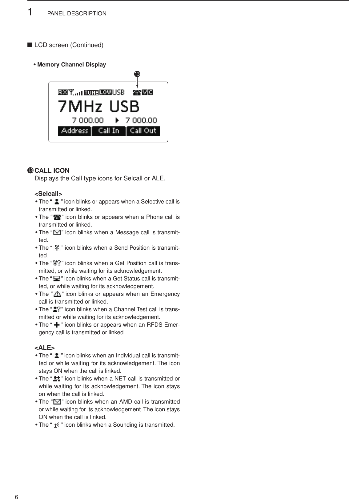
![2001 NEW51PANEL DESCRIPTION1234567891011121314151617Quick Referenceq RECEIVE/TRANSMIT ICON ➥ “ RX” appears when signals are received or the squelch is open. ➥ “ TX” appears when transmitting.w S-METER/TX METERS ➥ Displays the receive signal strength. ➥ Displays the transmit output power.e TUNE ICON Appears after the automatic antenna tuner matches the transceiver and antenna. NOTE: Appears only the frequency is set to within 10 Hz of the tuned frequency.r OUTPUT POWER ICON ➥ “HI” appears when high power is selected. ➥ “MID” appears when mid power is selected. ➥ “LOW” appears when low power is selected.t OPERATING MODE INDICATOR Displays the selected operating mode. • “LSB,” “USB,” “CW,” “AM,” RTTY,” “LSBD1,” “USBD1,” “LSBD2,” “USBD2,” “LSBD3” or “USBD3” appears, de-pending on the operating mode. Selectable operating modes differ depending on the transceiver version and/or preprogramming. y MUTE ICON ➥ “S” appears when the Call squelch function is se-lected. ➥ “L” appears when the S-meter squelch is se-lected. ➥ “V” appears when the Voice squelch is selected.u CLEAR TALK ICON Appears when the Clear Talk function is ON.i MAIN READOUTS <Memory Channel display> Displays the channel name. <VFO display> Displays the operating frequency.o SUB READOUTS <Memory Channel display> Displays the selected information. • ‘Frequencies,’ ‘Latitude and Longitude,’ ‘Direction and El-evation,’ ‘Antenna SWR and Power source voltage’ and ‘Date and Time’ can be displayed.‘Latitude and Longitude’ and ‘Direction and Elevation’ re-quire data from a GPS unit. • When the frequencies are displayed, the receive fre-quency is displayed on the right and the transmit fre-quency is displayed on the left. • “u” appears beside the receive or transmit frequencies, and indicates which one is active. • “p” or “q” appears instead of “u” to the right of the re-ceive frequency, when the Clarifier function is ON, and it indicates the upper or lower shift. NOTE: No transmit frequency is displayed when the selected channel is configured as “receive only.” <VFO display> Shows the transmit or receive frequency when VFO split is ON.!0 FUNCTION DISPLAY Displays the function of the [§], [§§] and [§§§] func-tion keys.!1 VFO ICON <VFO display> ➥ “A” appears when VFO A is selected. ➥ “B” appears when VFO B is selected. !2 CLARIFIER ICON <VFO display> “ p” or “q” appears when the Clarifier function is ON, and indicates the upper or lower shift. • Memory Channel Display • VFO Displayq w r t yu q w r t y ue e!1!3!2ioio!0 !0!2■ LCD screenContinued on the next page.](https://usermanual.wiki/ICOM-orporated/350000/User-Guide-1993755-Page-11.png)
![2001 NEW27BASIC OPERATION2001 NEW1234567891011121314151617Quick ReferencePush q[ ] to turn ON the Power. • If the “Built-in Test Display” item of “Setmode” is set to ON, ‘Built in Test’ appears. (Main Menu > Setmode > Config) • If the “User” item of “Setmode” is programmed, “Login” appears. (Main Menu > Setmode > Password) Push the keypad keys to enter either the User wpassword or Administrator password, and then push [4]. • Repeatedly push [A/a](#) to select the character group, ABC (upper case letters), abc (lower case letters) or 123 (numbers). • Push [8] to delete a character. • Push [t](§) or [u](§§§) to move the cursor. NOTE: • If you want to change any settings, you must be in the Administrator mode. • You can log into the Administrator mode with the “Admin Login” item in the Manager Menu screen (p. 34). [][]KeypadPower ON ■ Push q[8] to enter the Main Menu screen. Push w[r] or [s] to select “Channel” or “VFO,” and then push [4]. • If “Channel” is selected, the Memory Channel display appears. • If “VFO” is selected, the VFO display appears./Selecting the display mode ■Memory channel display VFO displayMain Menu screen](https://usermanual.wiki/ICOM-orporated/350000/User-Guide-1993755-Page-13.png)
 one or more times to select a squelch type. • Selectable types are Call SQL, S-meter SQL (level 0 to 50), Voice SQL and OFF. • The S-meter squelch level can be adjusted by the “Me-ter Squelch Level” item of “Setmode.” (Main Menu > Setmode > Config)Mute icon • The Mute icon, “S,” “L” or “V,” appears when the squelch function, Call SQL, S-meter SQL or Voice SQL is turned ON. NOTE: The Call squelch function cannot be se-lected in the VFO mode.➥ Push [ +] or [ –] to adjust the audio level. • If the squelch is closed, push [MUTE](M) one or more times to open the squelch. • The display shows the volume level while adjusting. Minimum audio level•••Maximum audio level■ Squelch function■ Setting audio volume Select the Memory Channel Display. qq Push [8] to enter the Main Menu screen.w Push [r] or [s] to select “Channel,” and then push [4]. Push w[r] or [s] to select a desired memory chan-nel. •••■ Selecting a channel](https://usermanual.wiki/ICOM-orporated/350000/User-Guide-1993755-Page-14.png)
![2001 NEW92BASIC OPERATION1234567891011121314151617Quick ReferenceThe scan function repeatedly scans programmed channels. This function is convenient to check for calls on multiple channels.[Stop]q Push [ ] to start a scan.• “Scanning” and the Scan type are displayed.w When a signal is received, the scan pauses on that channel.e Push [Stop](§§) to cancel the scan.• Pushing [ ] also cancels the scan. NOTE: The scan resume setting, the action after receiving a signal, can be changed by the “Voice Scan Resume” item of “Setmode.” (Main Menu > Setmode > Config)■ Scan functionThe following modes are selectable in the IC-F8101:LSB, USB, CW, AM, RTTY, LSBD1/2/3 and USBD1/2/3. NOTE: Only the preprogrammed operating modes are selectable. The selectable operating mode can be changed in the “Mode” item of “Setmode.” (Main Menu > Setmode) Select the Display mode. qq Push [8] to enter the Main Menu screen.w Push [r] or [s] to select “Channel” or “VFO,” and then push [4].w Push [Mode](3) one or more times to select the desired mode. • The selected mode icon appears at the top of the display. NOTE: • On the Memory Channel display, the selected operating mode can be used only temporarily. When the channel is changed, the transceiver returns to the preprogrammed operating mode. • Depending on the transceiver version or prepro-gramming, some operating modes may not be selectable or usable except in receive.■ Mode selectionFor your reference DMode TX/RX offset frequency [Hz] RX filter band width [Hz]Modulation inputMIC PTT ON MODEM PTT ONLSB, USB 1500 (Fixed)100 to 3000 (100Hz step) MICTC4, ACC, USBLSBD1, USBD1 1500, 1650, 1800 TC4, ACC, USBLSBD2, USBD2 1500, 1650, 1800 TC4, ACC, USBLSBD3, USBD3 1500, 1650, 1800 TC4, ACC, USBDefault settings are shown in bold.](https://usermanual.wiki/ICOM-orporated/350000/User-Guide-1993755-Page-15.png)
![2001 NEW102BASIC OPERATION2001 NEWIn the VFO mode, you can set a desired operating fre-quency, operating mode or split frequency function. NOTE: • The VFO mode operation can be disabled by the “VFO Mode” item of “Setmode.” (Main Menu > Setmode > Config)•While in the VFO mode, the Selcall, ALE features, Scan function or the Emergency key cannot be used.•EnteringtheVFOmode Push q[8] to enter the Main Menu screen. Push w[r] or [s] to select “VFO,” and then push [4].•Frequencysetting Push q[A/B](§§) to select VFO A or VFO B. Push w[t](§) or [u](§§§) to move the cursor to se-lect the desired digit to be changed. • The cursor is displayed below the selected digit. Push e[r] or [s] to change the digit.•Directfrequencysetting Push q[A/B](§§) to select VFO A or VFO B. Hold down w[4] for 1 second to enter the direct fre-quency input mode. • The previously entered frequency blinks. Push the keypad to enter the desired frequency. e • Push [M] to enter the decimal point. • Push [8] to delete the number. • Push [t](§) or [u](§§§) to move the cursor. Push r[4] to save the frequency and exit.[��][���][�]/Keypad•TurningONtheSplitfrequencyfunction Push q[8] to enter the Main Menu screen. Select the “VFO Split” item of “Setmode.” wq Push [r] or [s] to select the item, and then push [4] to open the screen. (Setmode > Config)w Push [r] or [s] to select “VFO Split,” and then hold down [4] for 1 second. Push e[r] or [s] to turn ON the function. • If desired, hold down [Default](§§) for 1 second to re-turn to the default setting. Push r[4] to save the setting, and return to the pre-vious screen. Push t[8] one or more times to exit the Main Menu screen. Enter the VFO mode. (See details to the left.) y Push u[A/B](§§) to select VFO A or VFO B, and sep-arately set the receive and transmit frequencies. • The TX frequency appears below the RX frequency. • Push [A/B](§§) changes the VFOs between transmit and receive. • Hold down [A/B](§§) for 1 second to equalize the trans-mit frequency to the receive frequency. • To turn OFF the Split frequency function, set the “VFO Split” item of “Setmode.” to “OFF.” (Main Menu > Setmode > Config)■ VFO operation](https://usermanual.wiki/ICOM-orporated/350000/User-Guide-1993755-Page-16.png)
 one or more times to turn OFF the mute.Mute iconw Push [r] or [s] to select the desired receive chan-nel. • The S-meter shows the signal strength when a signal is received.e Push [+] or [–] to adjust the desired audio level when receiving a signal. • If the bass or treble of the receive audio is too strong, push [CLAR](7) to set “Clarifier” to ON, and adjust to obtain clear audio. (See page 14 for the Clarifier func-tion details.) • If the audio is distorted, select the suitable operating mode. (See page 9 for the Mode selection details.)r Push [TUNE](9) to enter the antenna tune mode. • The “Auto Tune” screen appears. NOTE: The antenna tune mode must be set to ON by the “Tuner” item of “Setmode.” (Default: ON) (Main Menu > Setmode > Config) Push t[4] to start auto tuning. • The display shows the antenna SWR. • If the antenna cannot be tuned after 20 seconds, the tuning circuit is automatically bypassed. • After tuning is nished, the auto tune automatically stops transmitting. • If necessary, push [8] to manually stop transmitting. • Push [Through](§§) to turn OFF the antenna tuner. After tuning is finished, push y[TUNE](9) again to return to the normal operating screen. To transmit on the channel, hold down u[PTT] on the microphone, and speak at a normal voice level. • The RF meter shows the output power.Release i[PTT] to receive.](https://usermanual.wiki/ICOM-orporated/350000/User-Guide-1993755-Page-17.png)
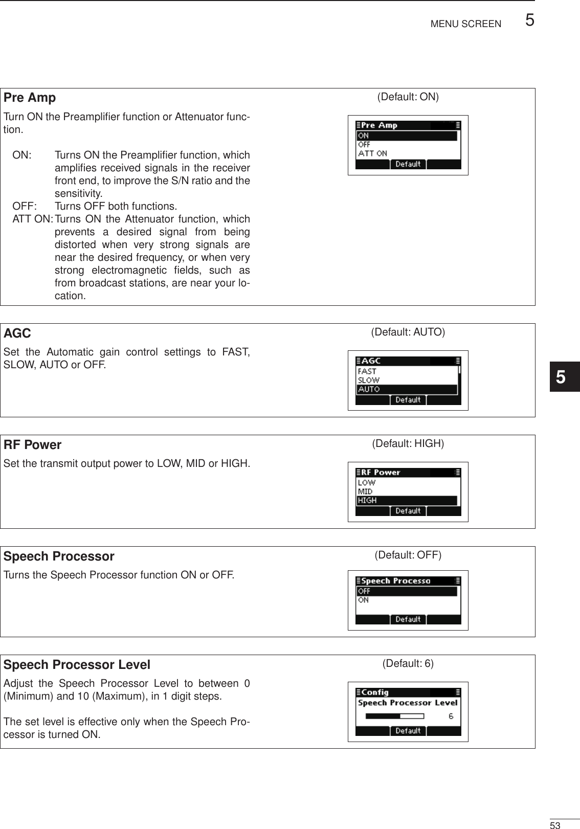
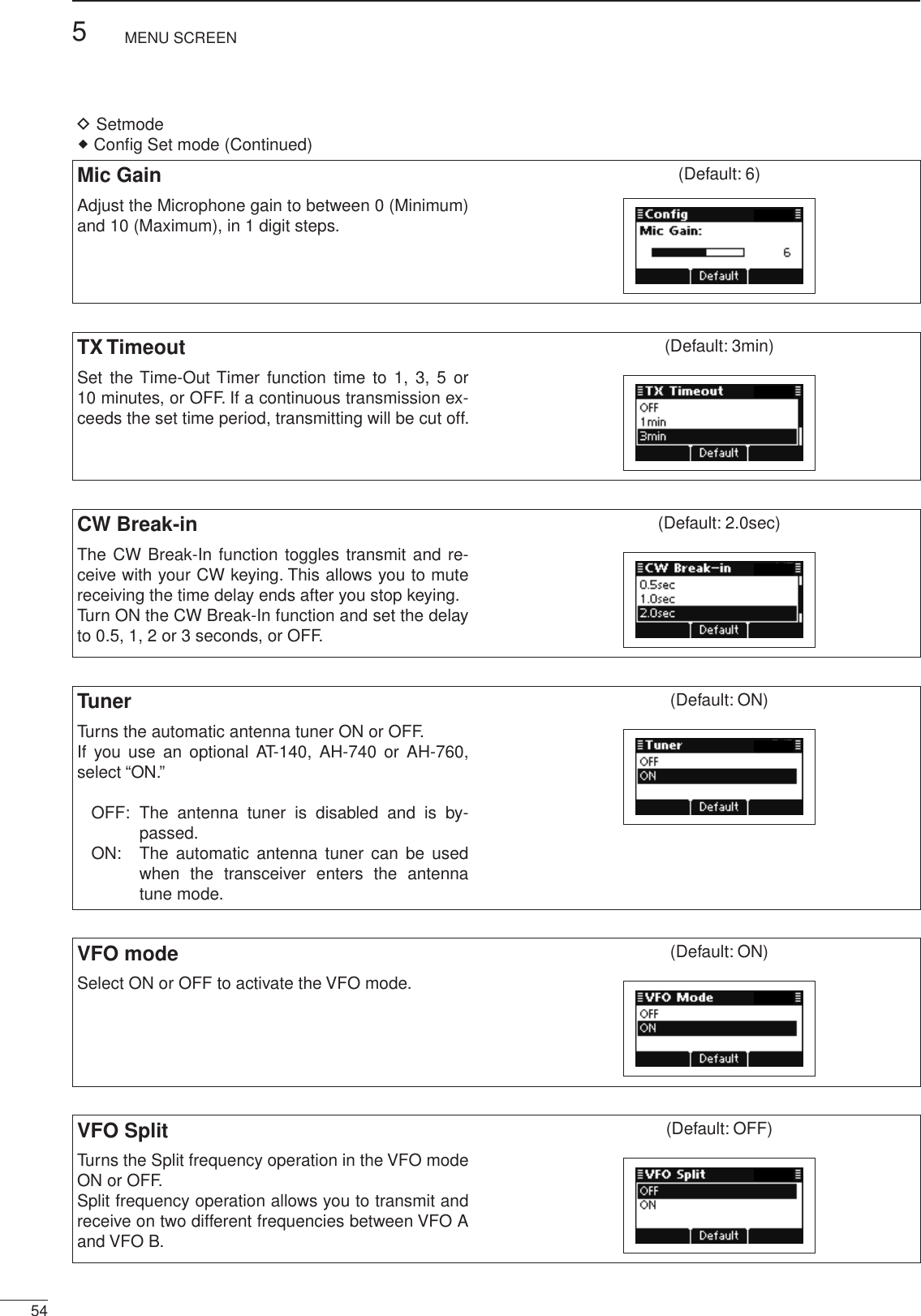
![Functions for transmit ■Transmit power selection DThe transceiver has three output power levels, HIGH, MID and LOW. High power provides longer distance communications and low power reduces power con-sumption.[Default]/ Push q[8] to enter the Main Menu screen. Select the “RF Power” item of “Setmode.” wq Push [r] or [s] to select the item, and then push [4] to open the screen. (Setmode > Config)w Push [r] or [s] to select “RF power,” and then hold down [4] for 1 second. Push e[r] or [s] to select the desired option, LOW, MID or HIGH. • If desired, hold down [Default](§§) for 1 second to re-turn to the default setting. Push r[4] to save the setting, and return to the pre-vious screen. Push t[8] one or more times to exit.Setting Microphone gain DThe microphone gain must be properly adjusted so that your signal is not distorted when transmitted.[Default]/ Push q[8] to enter the Main Menu screen. Select the “Mic Gain” item of “Setmode.” wq Push [r] or [s] to select the item, and then push [4] to open the screen. (Setmode > Config)w Push [r] or [s] to select “Mic Gain,” and then hold down [4] for 1 second. Push e[r] or [s] to adjust the desired setting level to between 0 and 10. • If desired, hold down [Default](§§) for 1 second to re-turn to the default setting. Push r[4] to save the setting, and return to the pre-vious screen. Push t[8] one or more times to exit.123RECEIVE AND TRANSMIT2001 NEW 2001 NEW](https://usermanual.wiki/ICOM-orporated/350000/User-Guide-1993755-Page-18.png)
![133RECEIVE AND TRANSMIT3Speech Processor DThe IC-F8101 has a built-in, low distortion Speech Processor circuit. This circuit increases your average talk power in the SSB mode, and is especially useful when the receiving station is having difficulty hearing your audio.[Default]/ Push q[8] to enter the Main Menu screen. Select the “Speech Processor” item of “Setmode.” wq Push [r] or [s] to select the item, and then push [4] to open the screen. (Setmode > Config)w Push [r] or [s] to select “Speech Processor,” and then hold down [4] for 1 second. Push e[r] or [s] to turn ON the function. • If desired, hold down [Default](§§) for 1 second to re-turn to the default setting. Push r[4] to save the setting, and return to the pre-vious screen. • If desired, adjust the Speech Processor Level. See the next topic for details. Push t[8] one or more times to exit. Push y[MODE](3) one or more times to select the USB or LSB mode. Hold down u[PTT] on the microphone, and speak at a normal voice level.Speech Processor Level DThe Speech Processor level must be properly adjust-ed so that your signal is not distorted when transmit-ted.[Default]/ Push q[8] to enter the Main Menu screen. Select the “Speech Processor Level” item of “Set- wmode.”q Push [r] or [s] to select the item, and then push [4] to open the screen. (Setmode > Config)w Push [r] or [s] to select “Speech Processor Level” and then hold down [4] for 1 second. Push e[r] or [s] to adjust the desired level to be-tween 0 and 10. • If desired, hold down [Default](§§) for 1 second to re-turn to the default setting. Push r[4] to save the setting, and return to the pre-vious screen. Push t[8] one or more times to exit.2001 NEW](https://usermanual.wiki/ICOM-orporated/350000/User-Guide-1993755-Page-19.png)
 to open the Clarifier adjustment window.Push w[r] or [s] to adjust the frequency shift. • The transmit frequency is not shifted. Push e[CLAR](7) to save the setting, and return to the previous screen. • If desired, push [8] to cancel the setting and exit the window . When cancelling the Clarifier function, set the fre-quency shift to 0 Hz in the Clarifier adjustment win-dow.Preamp and Attenuator DThe preamp amplifies received signals in the front end circuit to improve the S/N ratio and sensitivity. Turn ON this function to better receive weak signals.The attenuator prevents strong undesired signals near the desired frequency or near your location, such as from a broadcast station, from causing distortion or spurious signals.[Default]/ Push q[8] to enter the Main Menu screen. Select the “Pre Amp” item of “Setmode.” wq Push [r] or [s] to select the item, and then push [4] to open the screen. (Setmode > Config)w Push [r] or [s] to select “Pre Amp,” and then hold down [4] for 1 second. Push e[r] or [s] to select the desired option, ON, OFF or ATT ON. • If desired, hold down [Default](§§) for 1 second to re-turn to the default setting. Push r[4] to save the setting, and return to the pre-vious screen. Push t[8] one or more times to exit.](https://usermanual.wiki/ICOM-orporated/350000/User-Guide-1993755-Page-20.png)
![315RECEIVE AND TRANSMIT32001 NEWNoise Blanker DThe noise blanker reduces pulse-type noise such as that generated by automobile ignition systems.[Default]/When using the Noise Blanker function, received signals may be distorted if they are excessively strong, or when used on noise other than pulses. In this case, set the Noise Blanker threshold level to a shallow position, or turn OFF the function. (See next topic.) Push q[8] to enter the Main Menu screen. Select the “Noise Blanker” item of “Setmode.” wq Push [r] or [s] to select the item, and then push [4] to open the screen. (Setmode > Config)w Push [r] or [s] to select “Noise Blanker,” and then hold down [4] for 1 second. Push e[r] or [s] to turn ON the function. • If desired, hold down [Default](§§) for 1 second to re-turn to the default setting. Push r[4] to save the setting, and return to the pre-vious screen. • If desired, adjust the Noise Blanker Level or Noise Blanker Depth. See the next topic for details. Push t[8] one or more times to exit.Noise Blanker adjustment DTo deal with various types of noise, the threshold level and attenuation level can be set by the “Noise Blanker Level” and “Noise Blanker Depth” items.[Default]/ Push q[8] to enter the Main Menu screen. Select the “Noise Blanker Level” or “Noise Blanker wDepth” item of “Setmode.”q Push [r] or [s] to select the item, and then push [4] to open the screen. (Setmode > Config)w Push [r] or [s] to select “Noise Blanker Level” or “Noise Blanker Depth,” and then hold down [4] for 1 second. Push e[r] or [s] to adjust to the desired level. • If desired, hold down [Default](§§) for 1 second to re-turn to the default setting. Noise Blanker Level: Between 0 and 15. Noise Blanker Depth: Between 0 and 9. Push r[4] to save the setting, and return to the pre-vious screen. Push t[8] one or more times to exit.](https://usermanual.wiki/ICOM-orporated/350000/User-Guide-1993755-Page-21.png)
![163RECEIVE AND TRANSMIT2001 NEW 2001 NEW■ Functions for receive (Continued)AGC function DThe AGC (automatic gain control) controls receiver gain to produce a constant audio output level, even when the received signal strength varies by fading, and so on.The transceiver has two AGC characteristics; AUTO and time constants FAST and SLOW. [Default]/ Push q[8] to enter the Main Menu screen. Select the “AGC” item of “Setmode.” wq Push [r] or [s] to select the item, and then push [4] to open the screen. (Setmode > Config)w Push [r] or [s] to select “AGC,” and then hold down [4] for 1 second. Push e[r] or [s] to select the desired option, FAST, SLOW or AUTO. • If desired, hold down [Default](§§) for 1 second to re-turn to the default setting. When AUTO is selected, the AGC time constant varies, depending on the operating mode. Push r[4] to save the setting, and return to the pre-vious screen. Push t[8] one or more times to exit.AGC OFF function DWhen receiving weak signals with adjacent strong signals or noise, the AGC function may reduce the sensitivity. In this situation, the AGC function should be turned OFF.[Default]/ Push q[8] to enter the Main Menu screen. Select the “AGC” item of “Setmode.” wq Push [r] or [s] to select the item, and then push [4] to open the screen. (Setmode > Config)w Push [r] or [s] to select “AGC,” and then hold down [4] for 1 second.Push e[r] or [s] to turn OFF the function. • If desired, hold down [Default](§§) for 1 second to re-turn to the default setting. Push r[4] to save the setting, and return to the pre-vious screen. Push t[8] one or more times to exit.](https://usermanual.wiki/ICOM-orporated/350000/User-Guide-1993755-Page-22.png)
 to turn ON the Clear Talk function. • “C” appears when the Clear Talk function is ON.Appears • If desired, adjust the Clear Talk level. See the next topic for details. • If desired, push [C TALK](8) again to turn OFF the function.Clear Talk Level DThe Clear Talk Level must be adjusted for maximum readability. Setting the “Clear Talk Level” too high re-sults in audio signal masking or distortion. [Default]/ Push q[8] to enter the Main Menu screen. Select the “Clear Talk Level” item of “Setmode.” wq Push [r] or [s] to select the item, and then push [4] to open the screen. (Setmode > Config)w Push [r] or [s] to select “Clear Talk Level” and then hold down [4] for 1 second. Push e[r] or [s] to adjust the desired level to be-tween 1 and 15. • If desired, hold down [Default](§§) for 1 second to re-turn to the default setting. Push r[4] to save the setting, and return to the pre-vious screen. Push t[8] one or more times to exit.](https://usermanual.wiki/ICOM-orporated/350000/User-Guide-1993755-Page-23.png)
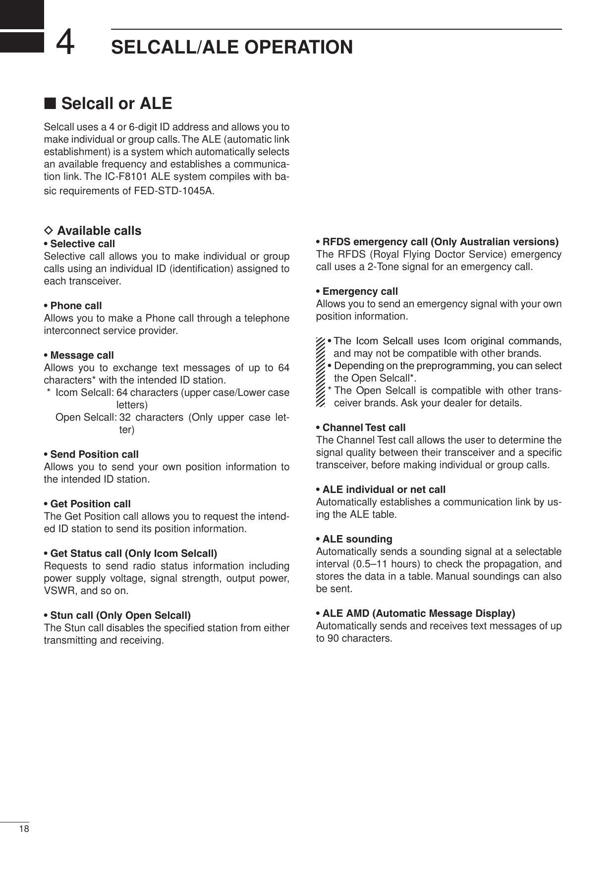
![194SELCALL/ALE OPERATION4The Selcall function allows you to make individual or group calls. Each transceiver is assigned an individual ID (identification) and can be called using this ID.•PreparationforaSelectivecallSend a Channel Test call on several Selcall channels, and check the propagation on each one to select the channel with the best signal quality. (p. 26)•SendingaSelectivecall Hold down q[ ] for 1 second to enter the Network selection screen. Push w[r] or [s] to select the desired Network, and then push [ ]. • The Networks that belong to the Icom Selcall or Open Selcall systems must be selected. Push e[r] or [s] to select the Call Type to “Selec-tive.” • “Selective,” “Phone,” “Message,” “Send Position,” “Get Posi-tion,” “Get Status,” “Emergency,” “Channel Test” and “Stun” are selectable. The Get Status call is selectable in the Icom Selcall, and the Stun call is selectable in the Open Selcall. Push keypad to enter the Call ID, and then push r[ ]. • The previously entered Call ID is displayed. • Push [t](§) or [u](§§§) to move the cursor. • Push [8] to delete the digit to the left of the cursor. • This Call ID is not stored in the Call ID list. Push t[r] or [s] to select the Profile, then push [ ]. Push y[r] or [s] to select the Channel. • Only the channels that belong to the selected Network in step w, are displayed. • If desired, push [Tests](§§) to transmit the Channel Test call in this step. Push u[ ] to transmit the Selective call. The call is stored in the Call Out memory. • While calling, push [PTT] to cancel the call. You can also make a Selective call when the Ad-dress screen is displayed. In this case, you can skip several steps, see page 29 for the Simple Selcall operation details.•ReceivingSelectivecallsWhen your transceiver receives a Selective call with your individual ID, it automatically responds by trans-mitting. The received Selcall is stored in the Call In memory. Push q[8] to enter the Main Menu screen. Push w[r] or [s] to select “Call In,” and then push [4]. Push e[r] or [s] to select the desired Call, and then push [4]. Push r[r] or [s] to select the information. Push t[8] twice to return to the normal operating screen.Selective call D](https://usermanual.wiki/ICOM-orporated/350000/User-Guide-1993755-Page-25.png)
![204SELCALL/ALE OPERATION2001 NEW 2001 NEWAllows you to make Phone calls through a telephone interconnect service provider.•PreparationforaPhonecallSend a Channel Test call on several Phone call chan-nels, and check the propagation on each one to select the channel with the best signal quality. (p. 26)• Sending a Phone call Hold down q[ ] for 1 second to enter the Network selection screen. Push w[r] or [s] to select the desired Network, and then push [ ]. • The Networks that belong to the Icom Selcall or Open Selcall systems must be selected. Push e[r] or [s] to select the Call Type to “Phone.” • “Selective,” “Phone,” “Message,” “Send Position,” “Get Posi-tion,” “Get Status,” “Emergency,” “Channel Test” and “Stun” are selectable. The Get Status call is selectable in the Icom Selcall, and the Stun call is selectable in the Open Selcall. Push keypad to enter the Number, and then push r[ ]. • The previously entered Number is displayed. • Push [t](§) or [u](§§§) to move the cursor. • Push [8] to delete the digit to the left of the cursor. • This Number is not stored in the Number list. Push keypad to enter the Phone Link ID, and then tpush [ ]. • The previously entered Link ID is displayed. • Push [t](§) or [u](§§§) to move the cursor. • Push [8] to delete the digit to the left of the cursor. • This ID is not stored in the Phone Link ID list. Push y[r] or [s] to select the Profile, then push [ ]. Push u[r] or [s] to select the Channel. • Only the channels that belong to the selected Network in step w, are displayed. • If desired, push [Tests](§§) to transmit the Channel Test call in this step. Push i[ ] to transmit the Phone call. The call is stored in the Call Out memory. • While calling, push [PTT] to cancel the call. You can also make a Phone call when the Address screen is displayed. In this case, you can skip sev-eral steps, see page 29 for the Simple Selcall opera-tion details.•AfteraPhonecallq When a Phone call is finished, push [ ] to trans-mit the disconnect call. • Until the Disconnect call is transmitted, the telephone interconnect service provider continues counting the time for toll charging. • If the “Auto Start Type” item of “Setmode” is set to “Scan” or “Termination,” the Call automatically disconnects after the Auto Start Wait Time period has past with no opera-tion. (Setmode > Call)Phone call D](https://usermanual.wiki/ICOM-orporated/350000/User-Guide-1993755-Page-26.png)
![2001 NEW214SELCALL/ALE OPERATION1234567891011121314151617Quick ReferenceThe Message call allows you to exchange text mes-sages of up to 64 characters,* with the intended ID station, and also leave a message at the station.* Icom Selcall: 64 characters (upper case/Lower case letters) Open Selcall: 32 characters (Only upper case letter)• Preparation for a Message callSend a Channel Test call on several Selcall channels, and check the propagation on each one to select the channel with the best signal quality. (p. 26)•SendingaMessagecall Hold down q[] for 1 second to enter the Network selection screen. Push w[r] or [s] to select the desired Network, and then push [ ]. • The Networks that belong to the Icom Selcall or Open Selcall systems must be selected. Push e[r] or [s] to select the Call Type to “Mes-sage.” • “Selective,” “Phone,” “Message,” “Send Position,” “Get Posi-tion,” “Get Status,” “Emergency,” “Channel Test” and “Stun” are selectable. The Get Status call is selectable in the Icom Selcall, and the Stun call is selectable in the Open Selcall. Push keypad to enter the Call ID, and then push r[ ]. • The previously entered Call ID is displayed. • Push [t](§) or [u](§§§) to move the cursor. • Push [8] to delete the digit to the left of the cursor. • This Call ID is not stored in the Call ID list. Select the desired Message or edit New message. t ❍ Message selection Push ➥[r] or [s] select the Message, and then push [ ]. ❍ New Message inputq Hold down [4] to enter the input mode.w Push keypad to enter the Message. • Push [A/a](#) to toggle between the Upper, Lower case letter input modes and Number in-put mode. • Push [8] to delete the character, symbol or num-ber to the left of the cursor. • Push [t](§) or [u](§§§) to move the cursor.e Push [4] to save the Message. • This Message is not stored in the Message list. Push y[r] or [s] to select the Profile, then push [ ]. Push u[r] or [s] to select the Channel. • Only the channels that belong to the selected Network in step w, are displayed. • If desired, push [Tests](§§) to transmit the Channel Test call in this step. Push i[ ] to transmit the Message call. The call is stored in the Call Out memory. • While calling, push [PTT] to cancel the call. You can also make a Message call when the Ad-dress screen is displayed. In this case, you can skip several steps, see page 29 for the Simple Selcall operation details.Message call D](https://usermanual.wiki/ICOM-orporated/350000/User-Guide-1993755-Page-27.png)
![224SELCALL/ALE OPERATION2001 NEW 2001 NEWThe Send Position call allows you to send your own position and time information to the intended ID sta-tion.•PreparationforaSendPositioncallSend a Channel Test call on several Selcall channels, and check the propagation on each one to select the channel with the best signal quality. (p. 26)•SendingaSendPositioncall Hold down q[ ] for 1 second to enter the Network selection screen. Push w[r] or [s] to select the desired Network, and then push [ ]. • The Networks that belong to the Icom Selcall or Open Selcall systems must be selected. Push e[r] or [s] to select the Call Type to “Send Position.” • “Selective,” “Phone,” “Message,” “Send Position,” “Get Posi-tion,” “Get Status,” “Emergency,” “Channel Test” and “Stun” are selectable. The Get Status call is selectable in the Icom Selcall, and the Stun call is selectable in the Open Selcall. Push keypad to enter the Call ID, and then push r[ ]. • The previously entered Call ID is displayed. • Push [t](§) or [u](§§§) to move the cursor. • Push [8] to delete the digit to the left of the cursor. • This Call ID is not stored in the Call ID list. Push t[r] or [s] to select the Profile, then push [ ]. Push y[r] or [s] to select the Channel. • Only the channels that belong to the selected Network in step w, are displayed. • If desired, push [Tests](§§) to transmit the Channel Test call in this step. Push u[ ] to transmit the Send Position call. The call is stored in the Call Out memory. • While calling, push [PTT] to cancel the call. You can also make a Send Position call when the Address screen is displayed. In this case, you can skip several steps, see page 29 for the Simple Sel-call operation details.•ReceivingSendPositioncallsWhen your transceiver receives a Send Position call with your individual ID, it automatically responds by transmitting. The received Selcall is stored in the Call In memory. Push q[8] to enter the Main Menu screen. Push w[r] or [s] to select “Call In,” and then push [4]. Push e[r] or [s] to select the desired Call, and then push [4]. Push r[r] or [s] to select the information. Push t[8] twice to return to the normal operating screen.Send Position call D](https://usermanual.wiki/ICOM-orporated/350000/User-Guide-1993755-Page-28.png)
![2001 NEW234SELCALL/ALE OPERATION1234567891011121314151617Quick ReferenceThe Get Position call allows you to request an intended ID station to send its position information.•PreparationforaGetPositioncallSend a Channel Test call on several Selcall channels, and check the propagation on each one to select the channel with the best signal quality. (p. 26)•SendingaGetPositioncall Hold down q[ ] for 1 second to enter the Network selection screen. Push w[r] or [s] to select the desired Network, and then push [ ]. • The Networks that belong to the Icom Selcall or Open Selcall systems must be selected. Push e[r] or [s] to select the Call Type to “Get Posi-tion.” • “Selective,” “Phone,” “Message,” “Send Position,” “Get Posi-tion,” “Get Status,” “Emergency,” “Channel Test” and “Stun” are selectable. The Get Status call is selectable in the Icom Selcall, and the Stun call is selectable in the Open Selcall. Push keypad to enter the Call ID, and then push r[ ]. • The previously entered Call ID is displayed. • Push [t](§) or [u](§§§) to move the cursor. • Push [8] to delete the digit to the left of the cursor. • This Call ID is not stored in the Call ID list. Push t[r] or [s] to select the Profile, then push [ ]. Push y[r] or [s] to select the Channel. • Only the channels that belong to the selected Network in step w, are displayed. • If desired, push [Tests](§§) to transmit the Channel Test call in this step. Push u[ ] to transmit the Send Position call. The call is stored in the Call Out memory. • While calling, push [PTT] to cancel the call. You can also make a Get Position call when the Ad-dress screen is displayed. In this case, you can skip several steps, see page 29 for the Simple Selcall operation details.•ReceivingaGetPositioncallacknowledgement After the call is transmitted, your called station qsends position and time information as an acknowl-edgement. Push any key to return to the normal operating wscreen. Push e[8] to enter the Main Menu screen. Push r[r] or [s] to select “Call In,” and then push [4]. Push t[r] or [s] to select the desired Call, and then push [4]. Push y[r] or [s] to select the information. Push u[8] twice to return to the normal operating screen.•ReceivingaGetPositioncallWhen your transceiver receives a Get Position call that includes your individual ID, it automatically responds by transmitting.Get Position call D](https://usermanual.wiki/ICOM-orporated/350000/User-Guide-1993755-Page-29.png)
![244SELCALL/ALE OPERATION2001 NEW 2001 NEWThe Get Status call requests sending radio status information including power supply voltage, signal strength, output power, VSWR, and so on.•PreparationforaGetStatuscallSend a Channel Test call on several Selcall channels, and check the propagation on each one to select the channel with the best signal quality. (p. 26)•SendingaGetStatuscall Hold down q[ ] for 1 second to enter the Network selection screen. Push w[r] or [s] to select the desired Network, and then push [ ]. • The Networks that belong to the Icom Selcall or Open Selcall systems must be selected. Push e[r] or [s] to select the Call Type to “Get Sta-tus.” • “Selective,” “Phone,” “Message,” “Send Position,” “Get Posi-tion,” “Get Status,” “Emergency,” “Channel Test” and “Stun” are selectable. The Get Status call is selectable in the Icom Selcall, and the Stun call is selectable in the Open Selcall. Push keypad to enter the Call ID, and then push r[ ]. • The previously entered Call ID is displayed. • Push [t](§) or [u](§§§) to move the cursor. • Push [8] to delete the digit to the left of the cursor. • This Call ID is not stored in the Call ID list. Push t[r] or [s] to select the Profile, then push [ ]. Push y[r] or [s] to select the Channel. • Only the channels that belong to the selected Network in step w, are displayed. • If desired, push [Tests](§§) to transmit the Channel Test call in this step. Push u[ ] to transmit the Send Position call. The call is stored in the Call Out memory. • While calling, push [PTT] to cancel the call. You can also make a Get Status call when the Ad-dress screen is displayed. In this case, you can skip several steps, see page 29 for the Simple Selcall operation details.•ReceivingaGetStatuscallacknowledgement After the call is transmitted, your called station sends qstatus information as an acknowledgement. Push any key to return to the normal operating wscreen. Push e[8] to enter the Main Menu screen. Push r[r] or [s] to select “Call In,” and then push [4]. Push t[r] or [s] to select the desired Call, and then push [4]. Push y[r] or [s] to select the information. • Status information includes the power supply voltage, Signal strength, Transmit power, VSWR, Time, Self ID, Network and Channel/Mode. Push u[8] twice to return to the normal operating screen.•ReceivingaGetStatuscallWhen your transceiver receives a Get Status call that includes your individual ID, it automatically responds by transmitting. Get Status call (Only Icom Selcall) D](https://usermanual.wiki/ICOM-orporated/350000/User-Guide-1993755-Page-30.png)
![254SELCALL/ALE OPERATION42001 NEWThe Emergency call allows you to broadcast an emer-gency signal with your own position information.•SendinganEmergencycall Hold down q[ ] for 1 second to enter the Network selection screen. Push w[r] or [s] to select the desired Network, and then push [ ]. • The Networks that belong to the Icom Selcall or Open Selcall systems must be selected. Push e[r] or [s] to select the Call Type to “Emer-gency.” • “Selective,” “Phone,” “Message,” “Send Position,” “Get Posi-tion,” “Get Status,” “Emergency,” “Channel Test” and “Stun” are selectable. The Get Status call is selectable in the Icom Selcall, and the Stun call is selectable in the Open Selcall. Push keypad to enter the Call ID, and then push r[ ]. • The previously entered Call ID is displayed. • Push [t](§) or [u](§§§) to move the cursor. • Push [8] to delete the digit to the left of the cursor. • This Call ID is not stored in the Call ID list. Push t[r] or [s] to select the Profile, then push [ ]. Push y[r] or [s] to select the Channel. • Only the channels that belong to the selected Network in step w, are displayed. • If desired, push [Tests](§§) to transmit the Channel Test call in this step. Push u[ ] to transmit the Emergency call. The call is stored in the Call Out memory. • While calling, push [PTT] to cancel the call. You can also make an Emergency call when the Ad-dress screen is displayed. In this case, you can skip several steps, see page 29 for the Simple Selcall operation details.•ReceivingEmergencycallsWhen your transceiver receives an Emergency call with your individual ID, it automatically responds by transmitting. The received Selcall is stored in the Call In memory. After an Emergency call is received, transceiver dis- qplays the station’s position and its time. Push any key to return to the normal operating wscreen. Push e[8] to enter the Main Menu screen. Push r[r] or [s] to select “Call In,” and then push [4]. Push t[r] or [s] to select the desired Call, and then push [4]. Push y[r] or [s] to select the information. Push u[8] twice to return to the normal operating screen.Emergency call D](https://usermanual.wiki/ICOM-orporated/350000/User-Guide-1993755-Page-31.png)
![264SELCALL/ALE OPERATION2001 NEW 2001 NEWThe Channel Test call allows the user determine the signal quality between your transceiver and a specif-ic transceiver before an individual or group call. The Channel Test call is also used for checking the channel before sending any other calls.•SendingaChannelTestcall Hold down q[ ] for 1 second to enter the Network selection screen. Push w[r] or [s] to select the desired Network, and then push [ ]. • The Networks that belong to the Icom Selcall or Open Selcall systems must be selected. Push e[r] or [s] to select the Call Type to “Channel Test.” • “Selective,” “Phone,” “Message,” “Send Position,” “Get Posi-tion,” “Get Status,” “Emergency,” “Channel Test” and “Stun” are selectable. The Get Status call is selectable in the Icom Selcall, and the Stun call is selectable in the Open Selcall. Push keypad to enter the Call ID, and then push r[ ]. • The previously entered Call ID is displayed. • Push [t](§) or [u](§§§) to move the cursor. • Push [8] to delete the digit to the left of the cursor. • This Call ID is not stored in the Call ID list. Push t[r] or [s] to select the Profile, then push [ ]. Push y[r] or [s] to select the Channel. • Only the channels that belong to the selected Network in step w, are displayed. • If desired, push [Tests](§§) to transmit the Channel Test call in this step. Push u[ ] to transmit the Channel Test call. The call is stored in the Call Out memory. • While calling, push [PTT] to cancel the call. You can also make a Channel Test call when the Ad-dress screen is displayed. In this case, you can skip several steps, see page 29 for the Simple Selcall operation details.Channel Test call D](https://usermanual.wiki/ICOM-orporated/350000/User-Guide-1993755-Page-32.png)
![2001 NEW274SELCALL/ALE OPERATION1234567891011121314151617Quick ReferenceThe Stun call disables the specified station from either transmitting and receiving.•SendingaStuncall Hold down q[ ] for 1 second to enter the Network selection screen. Push w[r] or [s] to select the desired Network, and then push [ ]. • The Networks that belong to the Open Selcall system must be selected. Push e[r] or [s] to select the Call Type to “Stun.” • “Selective,” “Phone,” “Message,” “Send Position,” “Get Posi-tion,” “Get Status,” “Emergency,” “Channel Test” and “Stun” are selectable. The Get Status call is selectable in the Icom Selcall, and the Stun call is selectable in the Open Selcall. Push keypad to enter the Call ID, and then push r[ ]. • The previously entered Call ID is displayed. • Push [t](§) or [u](§§§) to move the cursor. • Push [8] to delete the digit to the left of the cursor. • This Call ID is not stored in the Call ID list. Push keypad to enter the specified station’s PIN tCode, and then push [ ]. • Push [t](§) or [u](§§§) to move the cursor. • Push [8] to delete the digit to the left of the cursor. Push y[r] or [s] to select the Profile, then push [ ]. Push u[r] or [s] to select the Channel. • Only the channels that belong to the selected Network in step w, are displayed. • If desired, push [Tests](§§) to transmit the Channel Test call in this step. Push i[ ] to transmit the Stun call. The call is stored in the Call Out memory. • While calling, push [PTT] to cancel the call.Stun call (Only Open Selcall) D](https://usermanual.wiki/ICOM-orporated/350000/User-Guide-1993755-Page-33.png)
![284SELCALL/ALE OPERATION2001 NEW 2001 NEWThe RFDS (Royal Flying Doctor Service) emergency call uses a 2-Tone signal for an emergency call.•SendinganRFDSemergencycall Hold down q[] for 1 second to enter the Network selection screen. Push w[r] or [s] to select the desired Network, and then push [ ]. • The Networks that belong to the RFDS systems must be selected. Push e[r] or [s] to select the Channel. • Only the channels that belong to the selected Network in step w, are displayed. Push r[ ] to transmit the RFDS emergency call. The call is stored in the Call Out memory. • While calling, push [PTT] to cancel the call.RFDS emergency call (only AUS versions) D](https://usermanual.wiki/ICOM-orporated/350000/User-Guide-1993755-Page-34.png)
![294SELCALL/ALE OPERATION42001 NEWSimple Selcall operation DThe Simple Selcall mode is convenient to transmit the often used Selcalls.Push q[ ] to enter the Simple Selcall mode. • Depending on the Entry, the contents are skipped. Holding down [ ] enters the normal Selcall mode. See pages 19 to 28 for the normal Selcall operation de-tails. After setting is finished, push w[r] or [s] to select the Channel. • Only the channels that belong to the selected Network, are displayed. • If desired, push [Tests](§§) to transmit the Channel Test call in this step. Push e[ ] to transmit the Call. • While calling, push [PTT] to cancel the call. Depending on the Entry, following settings are required.(4 : Setting is required. — : The contents is skipped.)Screen(Entry) Call system/Network Call type/Call ID PhoneLink*4Message*5Self ID*3Channel*6NoteAddressEmergency Link —*1—*3———4The skipped contents are used from the preprogrammed setting.Call InCall Out —*1—*3———4The skipped contents are used from the preprogrammed setting.Phone Link —*14 4 — — 4The Call type is always set to Phone.The skipped contents are used from the preprogrammed setting.Other screen — *24 4 4 —4The skipped contents are used from the previously transmitted Calls. *1 When the setting of the Entry is effective (Call is possible), the content is skipped.*2 Priority Network is used.*3 When the preprogrammed ID or previously used ID exists in the selected entry, the Call automatically selects the ID and skips the contents.*4 Only Phone call.*5 Only Message call.*6 Only the channels that belong to the Network, are displayed.](https://usermanual.wiki/ICOM-orporated/350000/User-Guide-1993755-Page-35.png)
![304SELCALL/ALE OPERATION2001 NEW 2001 NEWAutomatically establish a communication link by using the ALE table.•SendinganIndividualcall Hold down q[ ] for 1 second to enter the Network selection screen. Push w[r] or [s] to select the desired Network, and then push [ ]. • The Networks that belong to the ALE system must be selected. Push e[r] or [s] to select the Call Type to “Individ-ual.” • “Individual,” “NET Call,” “Sounding” and “AMD” are select-able. Push r[r] or [s] to select the Individual ID, and then push [ ]. • Only the ID that belong to the selected Network in step w, are displayed. Push t[r] or [s] to select the Self ID, then push [ ]. • Only the ID that belong to the selected Network in step w, are displayed. Push y[r] or [s] to select the Channel. • Only the channels that belong to the selected Network in step w, are displayed. • If <Auto> is selected, the transceiver sequentially trans-mits channels that belong to the Network. Push u[ ] to transmit the Individual call. The call is stored in the Call Out memory. • While calling, push [PTT] to cancel the call.• After an ALE call After an ALE call is finished, push ➥[ ] to transmit the disconnect call. • If the “Auto Start Type” item of “Setmode” is set to “Scan” or “Termination,” the Call automatically disconnects after the Auto Start Wait Time period has past with no opera-tion. (Setmode > Call)•SendingaNetcall Hold down q[ ] for 1 second to enter the Network selection screen. Push w[r] or [s] to select the desired Network, and then push [ ]. • The Networks that belong to the ALE system must be selected. Push e[r] or [s] to select the Call Type to “NET Call.” • “Individual,” “NET Call,” “Sounding” and “AMD” are select-able. Push r[r] or [s] to select the NET ID, and then push [ ]. • Only the ID that belong to the selected Network in step w, are displayed. Push t[r] or [s] to select the Self ID, then push [ ]. • Only the ID that belong to the selected Network in step w, are displayed. Push y[r] or [s] to select the Channel. • Only the channels that belong to the selected Network in step w, are displayed. • If <Auto> is selected, the transceiver sequentially trans-mits channels that belong to the Network. Push u[ ] to transmit the NET Call. The call is stored in the Call Out memory. • While calling, push [PTT] to cancel the call.ALE call D](https://usermanual.wiki/ICOM-orporated/350000/User-Guide-1993755-Page-36.png)
![314SELCALL/ALE OPERATION42001 NEWAutomatically sends a sounding signal at certain in-tervals (0.5–11 hours) to check the propagation, and then stores the data in a table. Manual soundings can also be made.•Manualsounding Hold down q[ ] for 1 second to enter the Network selection screen. Push w[r] or [s] to select the desired Network, and then push [ ]. • The Networks that belong to the ALE system must be selected. Push e[r] or [s] to select the Call Type to “Sound-ing.” • “Individual,” “NET Call,” “Sounding” and “AMD” are select-able. Push r[r] or [s] to select the Self ID, then push [ ]. • Only the ID that belong to the selected Network in step w, are displayed. Push t[r] or [s] to select the Channel. • Only the channels that belong to the selected Network in step w, are displayed. Push y[ ] to transmit the Sounding call. • While calling, push [PTT] to cancel the call.ALE Sounding D](https://usermanual.wiki/ICOM-orporated/350000/User-Guide-1993755-Page-37.png)
![2001 NEW324SELCALL/ALE OPERATION2001 NEWThe ALE AMD (Automatic Message Display) sends and receives test messages of up to 90 characters.•SendinganAMDcall Hold down q[ ] for 1 second to enter the Network selection screen. Push w[r] or [s] to select the desired Network, and then push [ ]. • The Networks that belong to the ALE system must be selected. Push e[r] or [s] to select the Call Type to “AMD.” • “Individual,” “NET Call,” “Sounding” and “AMD” are select-able. Push r[r] or [s] to select the Individual ID, and then push [ ]. • Only the ID that belong to the selected Network in step w, are displayed. Push t[r] or [s] to select the Self ID, then push [ ]. • Only the ID that belong to the selected Network in step w, are displayed. Select the desired Message or edit New message. t ❍ Message selection Push ➥[r] or [s] select the Message, and then push [ ]. ❍ New Message inputq Hold down [4] to enter the input mode.w Push keypad to enter the Message. • Push [A/a](#) to toggle between the Upper case letter and Number input mode. • Push [8] to delete the character, symbol or num-ber to the left of the cursor. • Push [t](§) or [u](§§§) to move the cursor.e Push [4] to save the Message. • This Message is not stored in the Message list. Push y[r] or [s] to select the Channel. • Only the channels that belong to the selected Network in step w, are displayed. • If <Auto> is selected, the transceiver sequentially trans-mits channels that belong to the Network. Push u[ ] to transmit the Individual call. The call is stored in the Call Out memory. • While calling, push [PTT] to cancel the call.• After an ALE call After an ALE call is finished, push ➥[ ] to transmit the disconnect call. • If the “Auto Start Type” item of “Setmode” is set to “Scan” or “Termination,” the Call automatically disconnects after the Auto Start Wait Time period has past with no opera-tion. (Setmode > Call)ALE AMD call D](https://usermanual.wiki/ICOM-orporated/350000/User-Guide-1993755-Page-38.png)
 to enter the Manager Menu screen. • “Admin Login” is automatically selected. If “Admin Log-in” is not selected, push [r] to select it. Push w[4] to enter the Administrator mode. • Depending on the preprogramming, the “Admin Login” may appear, and then the password is requested. Push the keypad keys to enter the Administrator epassword, and then push [4]. • Repeatedly push [A/a](#) to select the character group, ABC (upper case letters), abc (lower case letters) or 123 (numbers). • Push [8] to delete a character. • Push [t](§) or [u](§§§) to move the cursor./[][]KeypadD Return to the User mode Push q[MNGR](#) to enter the Manager Menu screen. • “Admin Logout” is automatically selected. If “Admin Logout” is not selected, push [r] to select it. Push w[4] to enter the User mode. • “Log out of Administrator” is displayed, and then the transceiver returns to the User mode./2001 NEW](https://usermanual.wiki/ICOM-orporated/350000/User-Guide-1993755-Page-40.png)
 to enter the Manager Menu screen. • “Admin Logout” is automatically selected. Push e[r] or [s] to select “Access Rights,” and then push [4]. Push r[r] or [s] to select the item, and then hold down [4] for 1 second. Push t[r] or [s] to select “ON,” and then push [4]. Hidden: Undisplayed in the Use mode. Lock: Locked and editing is restricted in the User mode. • The setting is effective after the transceiver returns to the User mode.Setting the Access Rights View DYou can confirm the restriction of the memory chan-nel, Selcall address or any other settings./(Display example) : Appears when the “Hidden” setting is ON. : Appears when the “Lock” setting is ON. : Appears when the Factory Lock setting is ON. This setting cannot be changed in either the Administrator or User mode. Push q[MNGR](#) to enter the Manager Menu screen. • “Admin Logout” is automatically selected. Push w[r] or [s] to select “Display,” and then push [4].Hold down e[4] for 1 second. Push r[r] or [s] to select “ON,” and then push [4]. Select the desired memory channel, Selcall ad- tdress or setting that you want to check in the “Ac-cess Rights” setting.](https://usermanual.wiki/ICOM-orporated/350000/User-Guide-1993755-Page-41.png)
 to enter the Manager Menu screen. • “Admin Logout” is automatically selected. Push w[r] or [s] to select “Built-in Test,” and then push [4]. Push e[r] or [s] to select the item, and then push [4] to start testing. • “Auto,” “Logic,” “Receiver” and “Transmitter” are select-able. • If any problems are found, “Test failed” appears. • If no problems are found, “Test passed” appears.Information DYou can display a variety of information by using the “Information” item./ Push q[MNGR](#) to enter the Manager Menu screen. • “Admin Logout” is automatically selected. Push w[r] or [s] to select “Information,” and then push [4]. Push e[r] or [s] to select the item, and then push [4] to display the information. • “Date/Time,” “GPS,” “Priority Network,” “Unit” and “Ver-sion” are selectable. • “GPS” requires data from an external GPS unit.2001 NEW](https://usermanual.wiki/ICOM-orporated/350000/User-Guide-1993755-Page-42.png)
 to enter the Manager Menu screen. • “Admin Logout” is automatically selected. Push w[r] or [s] to select “Create Entry,” and then push [4].Create the desired entry as follows. e • “ALE,” “Channel,” “Network” or “Selcall” can be select-ed.•ALEA Call ID, NET ID or Self ID can be created.Making a Call ID or Self ID Push q[r] or [s] to select “ALE,” and then push [4]. Push w[r] or [s] to select a Call ID or Self ID, and then push [4] to enter the input mode. Push Keypad to enter the desired ID, and then epush [4]. • Up to 15 characters can be entered. • Usable characters are A to Z, 0 to 9, ? and @. • Push [A/a](#) to toggle between the Alphabet (Upper case letter) input mode and Number input mode. • Push [8] to delete the character, symbol or number to the left of the cursor. • Push [t](§) or [u](§§§) to move the cursor. If the entered ID belongs to the specified NET ID, rpush [r] or [s] to select the ID, and then push [4]. • If the entered ID does not belong to any network, select (blank) and push [4]. If the entered ID uses with the specified Network tgroup, push [r] or [s] to select the Network, and then push [4]. • If the entered ID does not use with any network group, select (blank) and push [4]. If any NET ID is selected in step y r, select Slot number. • Selectable number are 1 to 20. Push u[4] to save the ID and exit.](https://usermanual.wiki/ICOM-orporated/350000/User-Guide-1993755-Page-43.png)
![385MENU SCREEN2001 NEW•ALEMaking a NET ID Push q[r] or [s] to select “ALE,” and then push [4]. Push w[r] or [s] to select a NET ID, and then push [4] to enter the input mode. Push Keypad to enter the desired ID, and then epush [4]. • Up to 15 characters can be entered. • Usable characters are A to Z, 0 to 9, ? and @. • Push [A/a](#) to toggle between the Alphabet (Upper case letter) input mode and Number input mode. • Push [8] to delete the character, symbol or number to the left of the cursor. • Push [t](§) or [u](§§§) to move the cursor. Push r[4] to save the ID and exit.•ChannelA new memory channel can be created. Push q[r] or [s] to select “Channel,” and then push [4] to enter the input mode. Push Keypad to enter the Channel name, and then wpush [4]. • Up to 20 characters can be entered. • See page 2 for the usable characters details. • Push [A/a](#) to toggle between the Upper, Lower case letter input modes and Number input mode. • Push [8] to delete the character, symbol or number to the left of the cursor. • Push [t](§) or [u](§§§) to move the cursor. Push Keypad to enter the receive frequency, and ethen push [4]. • Push [M] to enter the decimal point. • Push [8] to delete the number. • Push [t](§) or [u](§§§) to move the cursor. Push Keypad to enter the transmit frequency, and rthen push [4]. • Push [M] to enter the decimal point. • Push [8] to delete the number. • Push [t](§) or [u](§§§) to move the cursor. Push t[r] or [s] to select the operating mode. Push y[4] to save the channel and exit.Manager Menu ■Create Entry (Continued) D2001 NEW](https://usermanual.wiki/ICOM-orporated/350000/User-Guide-1993755-Page-44.png)
![2001 NEW395MENU SCREEN1234567891011121314151617Quick Reference•NetworkA new network can be created. Push q[r] or [s] to select “Network,” and then push [4] to enter the input mode. Push Keypad to enter the Network name, and then wpush [4]. • Up to 20 characters can be entered. • See page 2 for the usable characters details. • Push [A/a](#) to toggle between the Upper, Lower case letter input modes and Number input mode. • Push [8] to delete the character, symbol or number to the left of the cursor. • Push [t](§) or [u](§§§) to move the cursor. Push e[r] or [s] to select the Scan type, and then push [4] to select or deselect. • “4” appears to the left of the selected scan type. • If desired, up to three scan types can be selected. Hold down r[4] for 1 second to go to the next screen. Push t[r] or [s] to select the Call system, and then push [4]. Push y[r] or [s] to select the Call detect time, and then push [4]. Push u[r] or [s] to select the Preamble, and then push [4]. • Selectable times are 1 to 60 seconds and Auto. Push i[r] or [s] to select the Priority setting. • Priority setting can be set to only one Network. If this setting is set to ON, the previously selected Priority Network is automatically set to OFF. Push o[r] or [s] to select the memory channels, and then push [4] to select or deselect. • “4” appears to the left of the selected channel. • If desired, several channels can be selected.!0 Hold down [4] for 1 second to save the network and exit.](https://usermanual.wiki/ICOM-orporated/350000/User-Guide-1993755-Page-45.png)
![405MENU SCREEN2001 NEW•SelcallA new Selcall entry, Address, Phone Link or Profile, can be created.Making an Address Push q[r] or [s] to select “Selcall,” and then push [4]. Push w[r] or [s] to select “Address,” and then push [4] to enter the input mode. Push Keypad to enter the Address name, and then epush [4]. • Up to 20 characters can be entered. • See page 2 for the usable characters details. • Push [A/a](#) to toggle between the Upper, Lower case letter input modes and Number input mode. • Push [8] to delete the character, symbol or number to the left of the cursor. • Push [t](§) or [u](§§§) to move the cursor. Push r[r] or [s] to select the Call type. Then push keypad to enter the ID or number, and push [4]. • Push [8] to delete the character, symbol or number to the left of the cursor. • Push [t](§) or [u](§§§) to move the cursor. <Call type is other than Phone> • Up to 6 digits can be entered. <Call type is Phone> • Up to 16 digits can be entered. Push t[r] or [s] to select a network group or Phone Link. <Call type is other than Phone> <Call type is Phone> Push y[r] or [s] to select the Emergency Link ON or OFF. Push u[4] to save the channel and exit.Manager Menu ■Create Entry (Continued) D2001 NEW](https://usermanual.wiki/ICOM-orporated/350000/User-Guide-1993755-Page-46.png)
![2001 NEW415MENU SCREEN1234567891011121314151617Quick Reference•SelcallMaking a Phone Link Push q[r] or [s] to select “Selcall,” and then push [4]. Push w[r] or [s] to select “Phone Link,” and then push [4] to enter the input mode. Push Keypad to enter the Phone Link name, and ethen push [4]. • Up to 20 characters can be entered. • See page 2 for the usable characters details. • Push [A/a](#) to toggle between the Upper, Lower case letter input modes and Number input mode. • Push [8] to delete the character, symbol or number to the left of the cursor. • Push [t](§) or [u](§§§) to move the cursor. Push keypad to enter the ID, and then push r[4]. • Up to 6 digits can be entered. • Push [8] to delete the character, symbol or number to the left of the cursor. • Push [t](§) or [u](§§§) to move the cursor. Push t[r] or [s] to select a network group, and then push [4]. Push y[r] or [s] to select the memory channels. • Only the memory channels that belong to the selected network group in step t, are selectable. Push u[4] to save the Phone Link and exit.](https://usermanual.wiki/ICOM-orporated/350000/User-Guide-1993755-Page-47.png)
 to enter the Manager Menu screen. • “Admin Logout” is automatically selected. Push e[r] or [s] to select “Delete Entry,” and then push [4]. • The conrmation screen, “Delete Entry?” appears. Push r[s] to select “OK,” and then push [4].•SelcallMaking a Profile Push q[r] or [s] to select “Selcall,” and then push [4]. Push w[r] or [s] to select “Profile,” and then push [4] to enter the input mode. Push Keypad to enter the Profile name, and then epush [4]. • Up to 20 characters can be entered. • See page 2 for the usable characters details. • Push [A/a](#) to toggle between the Upper, Lower case letter input modes and Number input mode. • Push [8] to delete the character, symbol or number to the left of the cursor. • Push [t](§) or [u](§§§) to move the cursor. Push keypad to enter the ID, and then push r[4]. • Up to 6 digits can be entered. • Push [8] to delete the character, symbol or number to the left of the cursor. • Push [t](§) or [u](§§§) to move the cursor. Push t[r] or [s] to select a network group. Push y[4] to save the Profile and exit.Manager Menu ■Create Entry (Continued) D](https://usermanual.wiki/ICOM-orporated/350000/User-Guide-1993755-Page-48.png)
 to enter the Manager Menu screen. • “Admin Logout” is automatically selected. Push w[r] or [s] to select “Setup,” and then push [4].Create the desired entry as follows. e • “Channel,” “Network,” “ALE Self ID,” or “Selcall Profile” can be selected.•ChannelA new memory channel can be created. Push q[r] or [s] to select “Channel,” and then hold down [4] for 1 second to enter the input mode. Push Keypad to enter the Channel name, and then wpush [4]. • Up to 20 characters can be entered. • See page 2 for the usable characters details. • Push [A/a](#) to toggle between the Upper, Lower case letter input modes and Number input mode. • Push [8] to delete the character, symbol or number to the left of the cursor. • Push [t](§) or [u](§§§) to move the cursor. Push Keypad to enter the receive frequency, and ethen push [4]. • Push [M] to enter the decimal point. • Push [8] to delete the number. • Push [t](§) or [u](§§§) to move the cursor. Push Keypad to enter the transmit frequency, and rthen push [4]. • Push [M] to enter the decimal point. • Push [8] to delete the number. • Push [t](§) or [u](§§§) to move the cursor. Push t[r] or [s] to select the operating mode. Push y[4] to save the channel and exit.](https://usermanual.wiki/ICOM-orporated/350000/User-Guide-1993755-Page-49.png)
![445MENU SCREEN2001 NEWManager Menu ■Setup (Continued) D•NetworkA new network can be created. NOTE: The present Network list is cleared. Push q[r] or [s] to select “Network,” and then hold down [4] for 1 second to enter the input mode. Push w[r] or [s] to select the memory channels, and then push [4] to select or deselect. • “4” appears to the left of the selected channel. • If desired, several channels can be selected. Hold down e[4] for 1 second to go to the next screen. Push r[s] to select “OK,” and then push [4]. • If desired, select “Cancel” and then push [4].•ALESelfIDA Self ID can be created. NOTE: The present Self ID is cleared. Push q[r] or [s] to select “ALE Self ID,” and then hold down [4] for 1 second to enter the input mode. Push Keypad to enter the desired ID, and then wpush [4]. • Usable characters are A to Z, 0 to 9, ? and @. • Push [A/a](#) to toggle between the Alphabet (Upper case letter) input mode and Number input mode. • Push [8] to delete the character, symbol or number to the left of the cursor. • Push [t](§) or [u](§§§) to move the cursor. Push e[s] to select “OK,” and then push [4]. • If desired, select “Cancel” and then push [4].2001 NEW](https://usermanual.wiki/ICOM-orporated/350000/User-Guide-1993755-Page-50.png)
![2001 NEW455MENU SCREEN1234567891011121314151617Quick Reference•SelcallProleSelcall Profile can be created. NOTE: The present Selcall Profile is cleared. Push q[r] or [s] to select “Selcall Profile,” and then hold down [4] for 1 second to enter the input mode. Push Keypad to enter the desired ID, and then wpush [4]. • Up to 6 numbers can be entered. • Usable characters are A to Z, 0 to 9, ? and @. • Push [8] to delete the number to the left of the cursor. • Push [t](§) or [u](§§§) to move the cursor. Push e[s] to select “OK,” and then push [4]. • If desired, select “Cancel” and then push [4].](https://usermanual.wiki/ICOM-orporated/350000/User-Guide-1993755-Page-51.png)
![465MENU SCREEN2001 NEWMain Menu ■Entering the Main Menu D Push q[8] to enter the Main Menu screen. Push w[r] or [s] to select the item, and then push [4] to open the screen. • “ALE,” “Call In,” “Call Out,” “Channel,” “Network,” “Selcall,” “Setmode” or “VFO” can be selected. • If desired, push [8] to returns to the Memory channel screen. Push e[r] or [s] to select the item, and then push or hold down [4] to display or edit the screen./ALE DDisplays or edits the Entry of the list that is related to ALE.While displaying an Entry, hold down [4] for 1 second to enter the programing mode.Call ID Call IDDisplays the prepro-grammed Call ID list.IDDisplays the ID. ID editing modeNET IDDisplays the NET ID. NET ID selection modeNetworkDisplays the Network. Network selection modeSlotDisplays the Slot. Slot selection modeMessage MessageDisplays the prepro-grammed Message list.Message editing modeNET ID NET IDDisplays the prepro-grammed NET ID list.NET ID editing modeSelf ID Self IDDisplays the prepro-grammed Self ID list.IDDisplays the ID. ID editing modeNET IDDisplays the NET ID. NET ID selection modeNetworkDisplays the Network. Network selection modeSlotDisplays the Slot. Slot selection modeChannel DDisplays or edits the Memory channels.While displaying an Entry of the memory channel, hold down [4] for 1 second to enter the editing mode.Memory ChannelDisplays the prepro-grammed Memory channels.NameDisplays the Name. Name editing modeRX frequencyDisplays the RX frequency. RX frequency editing modeTX frequencyDisplays the TX frequency. TX frequency editing modeModeDisplays the Mode. Mode editing modeCall In/Call Out DDisplays the Entry of the Call In (Received Call) or Call Out (Send Call).2001 NEW](https://usermanual.wiki/ICOM-orporated/350000/User-Guide-1993755-Page-52.png)
![2001 NEW475MENU SCREEN1234567891011121314151617Quick ReferenceSelcall DDisplays or edits the Entry of the list that related to Selcall.While displaying an Entry, hold down [4] for 1 second to enter the programing mode.Address AddressDisplays the prepro-grammed Address list.NameDisplays the ID. Name editing mode.Type/IDDisplays the Call type and ID or number.Call type selection and ID or number editing mode.NetworkDisplays the Network. Network selection mode.ChannelDisplays the Channel. Channel selection mode.Phone LinkDisplays the Phone Link. Phone Link selection mode.MessageDisplays the Message. Message selection mode.Emergency LinkDisplays the Emergency Link setting ON or OFF.Emergency Link setting mode.Message MessageDisplays the prepro-grammed Message list.Message editing modePhone Link Phone LinkDisplays the prepro-grammed Phone Link list.NameDisplays the ID. Name editing mode.IDDisplays the ID. ID editing mode.NetworkDisplays the Network. Network selection mode.ChannelDisplays the Channel. Channel selection mode.Profile ProfileDisplays the prepro-grammed Profile list.NameDisplays the ID. Name editing mode.IDDisplays the ID. Call type selection and ID or number editing mode.NetworkDisplays the Network. Network selection mode.Network DDisplays or edits the Entry of the Network list.While displaying an Entry, hold down [4] for 1 second to enter the editing mode.NetworkDisplays the preprogrammed Network list.NameDisplays the Name. Name editing mode.Scan TypeDisplays the Scan Type. Scan Type selection mode.Call SystemDisplays the Call System. Call System selection mode.Call Detect TimeDisplays Detected Time. Call Detect Time selection mode.PreambleDisplays the Preamble time. Preamble time selection mode.Sounding IntervalDisplays the Sounding Interval. Sounding Interval selection mode.PriorityDisplays the Priority setting ON or OFF. Priority setting mode.ChannelsDisplays the selected channel number. Memory channel selection mode.](https://usermanual.wiki/ICOM-orporated/350000/User-Guide-1993755-Page-53.png)
![2001 NEW555MENU SCREEN1234567891011121314151617Quick ReferenceBuilt-in Test Display (Default: OFF)Select whether or not to display the device check screen after turning ON power. (Default: OFF) Emergency Set modeLink Interval (Default: 120sec)Set the Emergency Link interval time period to be-tween 10 and 300 seconds, in 10 seconds steps.The transceiver will sequentially send Emergency calls to the stations whose “Emergency Link” item is set to ON in Address of the SELCALL. Key Set modeI Key (Default: Address)The functions listed below can be set to the [I] key.Not assign: No function.Menu: Push to enter the Main Menu screen.Manager: Push to enter the Manager Menu screen.Setmode: Push to enter the Setmode screen.Address list: Push to display the Selcall address list.Call In list: Push to display the RX history screen.Call Out list: Push to display the TX history screen.II Key (Default: Call In list)The functions listed in the “I Key” item can be set to the [II] key.III Key (Default: Call Out list)The functions listed in the “I Key” item can be set to the [III] key.](https://usermanual.wiki/ICOM-orporated/350000/User-Guide-1993755-Page-61.png)
![565MENU SCREEN2001 NEW 2001 NEW Mode Set modeLSB Accept (Default: Disable for AUS, RX & TX for others)Set the LSB mode to “Disable,” “RX” or “RX & TX.”Disable: Disables the transceiver from both receiving and transmit-ting calls.RX: Allows the transceiver to re-ceive calls, but disables it from transmitting them.RX & TX: Allows the transceiver to both receive and transmit calls.Band WidthDisplays the IF filter passband width.The width is permanently set to “3000Hz.”Modem AF (Default: USB)Set the connector for data modulation input when an external unit’s [PTT] is pushed.TC4: Inputs the modulation signals through a RapidM TC4 HF Data Modem Module.ACC: Inputs the modulation signals through the ACC connector.USB: Inputs the modulation signals through a USB port.USB AcceptDisplays the USB mode permission set-ting.This setting is permanently set to “RX & TX.”Band WidthDisplays the IF filter passband width.The width is permanently set to “3000Hz.”Modem AF (Default: USB)Set the connector for data modulation input when an external unit’s [PTT] is pushed.See the “Modem AF” item in “LSB” for de-tails.Setmode D(Continued)](https://usermanual.wiki/ICOM-orporated/350000/User-Guide-1993755-Page-62.png)
![2001 NEW575MENU SCREEN1234567891011121314151617Quick ReferenceCW Accept (Default: Disable)Set the CW mode to “Disable,” “RX” or “RX & TX.”See the “Accept” item in “LSB” for details.Band WidthDisplays the IF filter passband width.The width is permanently set to “500Hz.”AM Accept (Default: RX for AUS, Disable for others)Set the AM mode to “Disable,” “RX” or “RX & TX.”See the “Accept” item in “LSB” for details.Band WidthDisplays the IF filter passband width.The width is permanently set to “8000Hz.”Modem AF (Default: USB)Set the connector for data modulation input when an external unit’s [PTT] is pushed.See the “Modem AF” item in “LSB” for de-tails.](https://usermanual.wiki/ICOM-orporated/350000/User-Guide-1993755-Page-63.png)
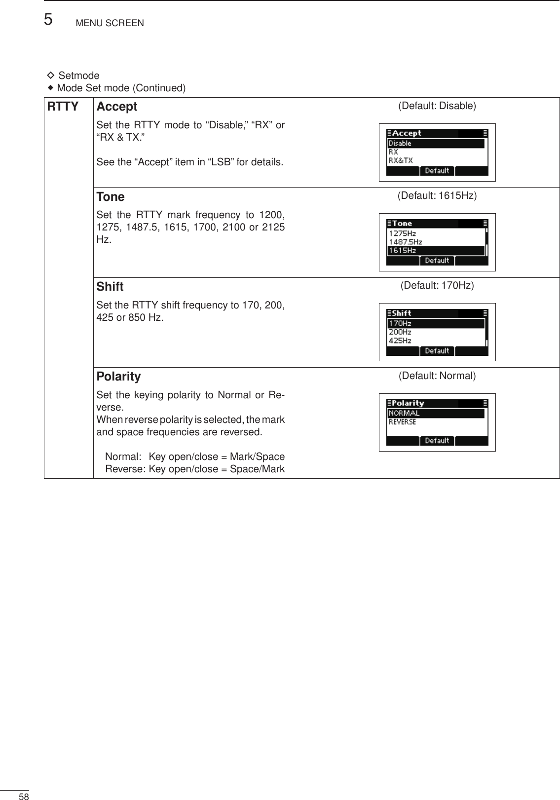
![2001 NEW595MENU SCREEN1234567891011121314151617Quick ReferenceLSBD1 Accept (Default: Disable)USBD1 Set the LSBD1 or USBD1 mode to “Dis-able,” “RX” or “RX & TX.”See the “Accept” item in “LSB” for details.OffsetDisplays the Offset frequency.The frequency is permanently set to “1800Hz.”Band WidthDisplays the IF filter passband width.The width is permanently set to “3000Hz.”Modem AF (Default: TC4)Set the connector for data modulation input when an external unit’s [PTT] is pushed.See the “Modem AF” item in “LSB” for de-tails.LSBD2 Accept (Default: Disable)USBD2 Set the LSBD2 or USBD2 mode to “Dis-able,” “RX” or “RX & TX.”See the “Accept” item in “LSB” for details.OffsetDisplays the Offset frequency.The frequency is permanently set to “1500Hz.”Band WidthDisplays the IF filter passband width.The width is permanently set to “3000Hz.”Modem AF (Default: ACC)Set the connector for data modulation input when an external unit’s [PTT] is pushed.See the “Modem AF” item in “LSB” for de-tails.](https://usermanual.wiki/ICOM-orporated/350000/User-Guide-1993755-Page-65.png)
![605MENU SCREEN2001 NEW 2001 NEWSetmode D Mode Set mode (Continued)LSBD3 Accept (Default: Disable)USBD3 Set the LSBD3 or USBD3 mode to “Dis-able,” “RX” or “RX & TX.”See the “Accept” item in “LSB” for details.OffsetDisplays the Offset frequency.The frequency is permanently set to “1650Hz.”Band WidthDisplays the IF filter passband width.The width is permanently set to “3000Hz.”Modem AF (Default: ACC)Set the connector for data modulation input when an external unit’s [PTT] is pushed.See the “Modem AF” item in “LSB” for de-tails. Password Set modeUserEnter a Login Password of up to 10 characters to en-ter the User mode.AdminEnter a Login Password of up to 10 characters to en-ter the Administrator mode. PIN Code Set modePIN CodeSet a PIN code of up to 10 digits.When the matched Selcall ID and PIN Code are re-ceived, the stun function is activated.](https://usermanual.wiki/ICOM-orporated/350000/User-Guide-1993755-Page-66.png)
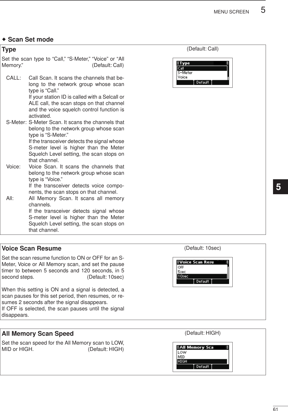
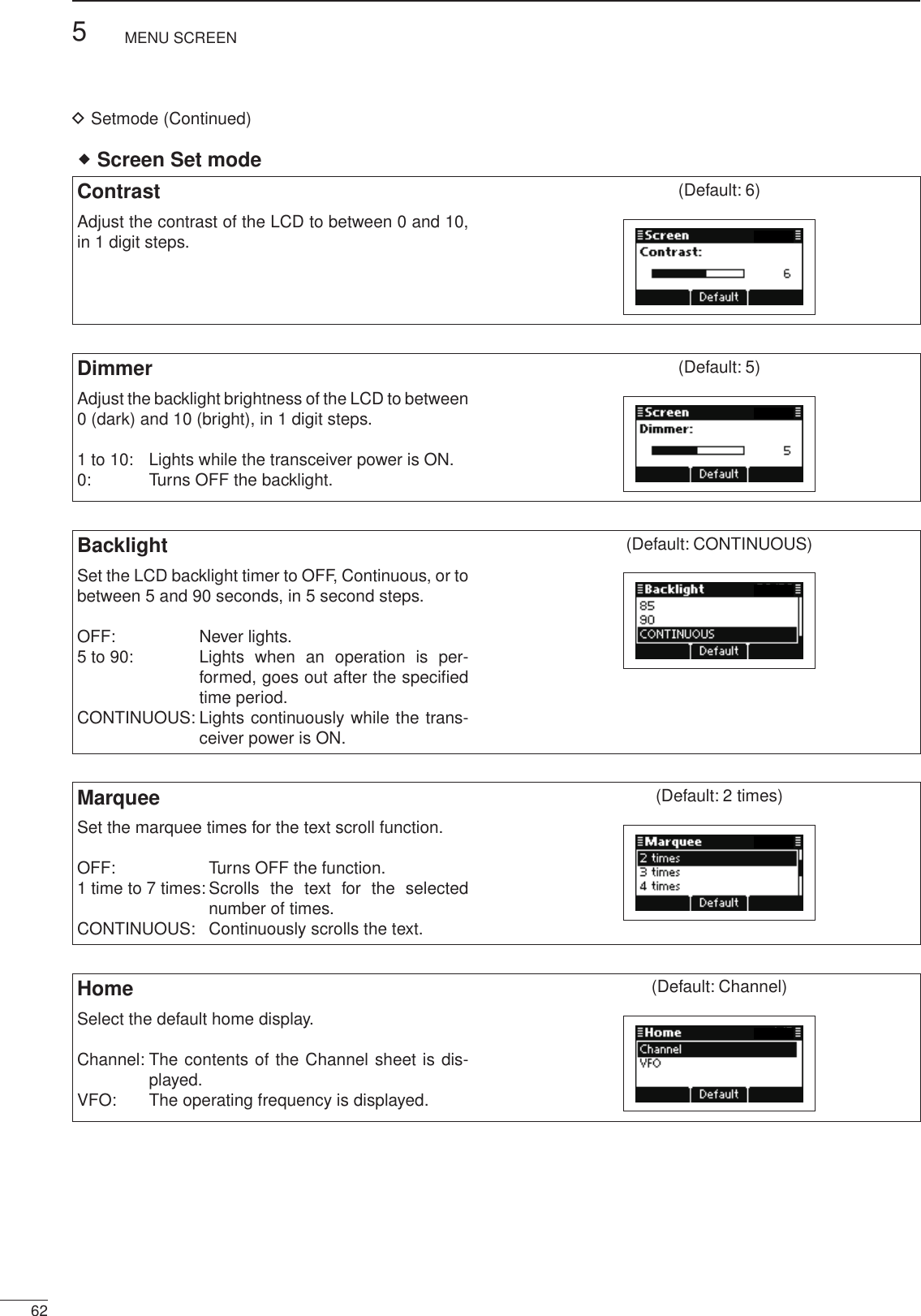
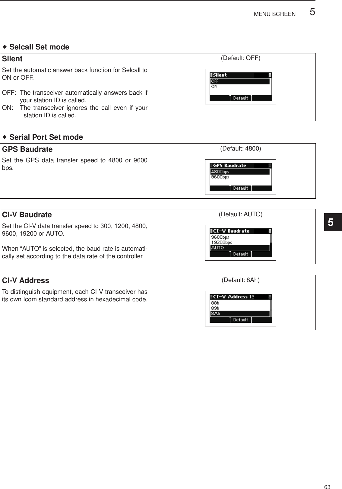
![645MENU SCREEN2001 NEW 2001 NEW Time Set modeLocalSet the Local time. Before programming this item, the “UTC Offset” item must be set. Push q[r] or [s] to select this item, and then hold down [4] to open the programming screen.Push w[r] or [s] to select the digit. • Push [4] to move the cursor right, push [8] to move the cursor left. After the ‘second’ digit is programmed, push e[4] to set the time and return to the previous screen.UTC OffsetSelect the time difference between UTC (Universal Time Coordinated) and the local time.–12.0 to + 12.0 (in 0.5* steps) * 0.5 = 30 minutes This item must be set before programming the “Lo-cal” item.Setmode D(Continued)](https://usermanual.wiki/ICOM-orporated/350000/User-Guide-1993755-Page-70.png)
![2001 NEW655MENU SCREEN1234567891011121314151617Quick ReferenceIf you want to initialize the operating settings in the Main Menu, without clearing memory channel con-tents or ID contents, do the following steps.q Turn OFF the transceiver power, if it is powered ON.w While holding down [r] and [s], and push [] to turn ON the transceiver power to reset the CPU./■ CPU Reset](https://usermanual.wiki/ICOM-orporated/350000/User-Guide-1993755-Page-71.png)
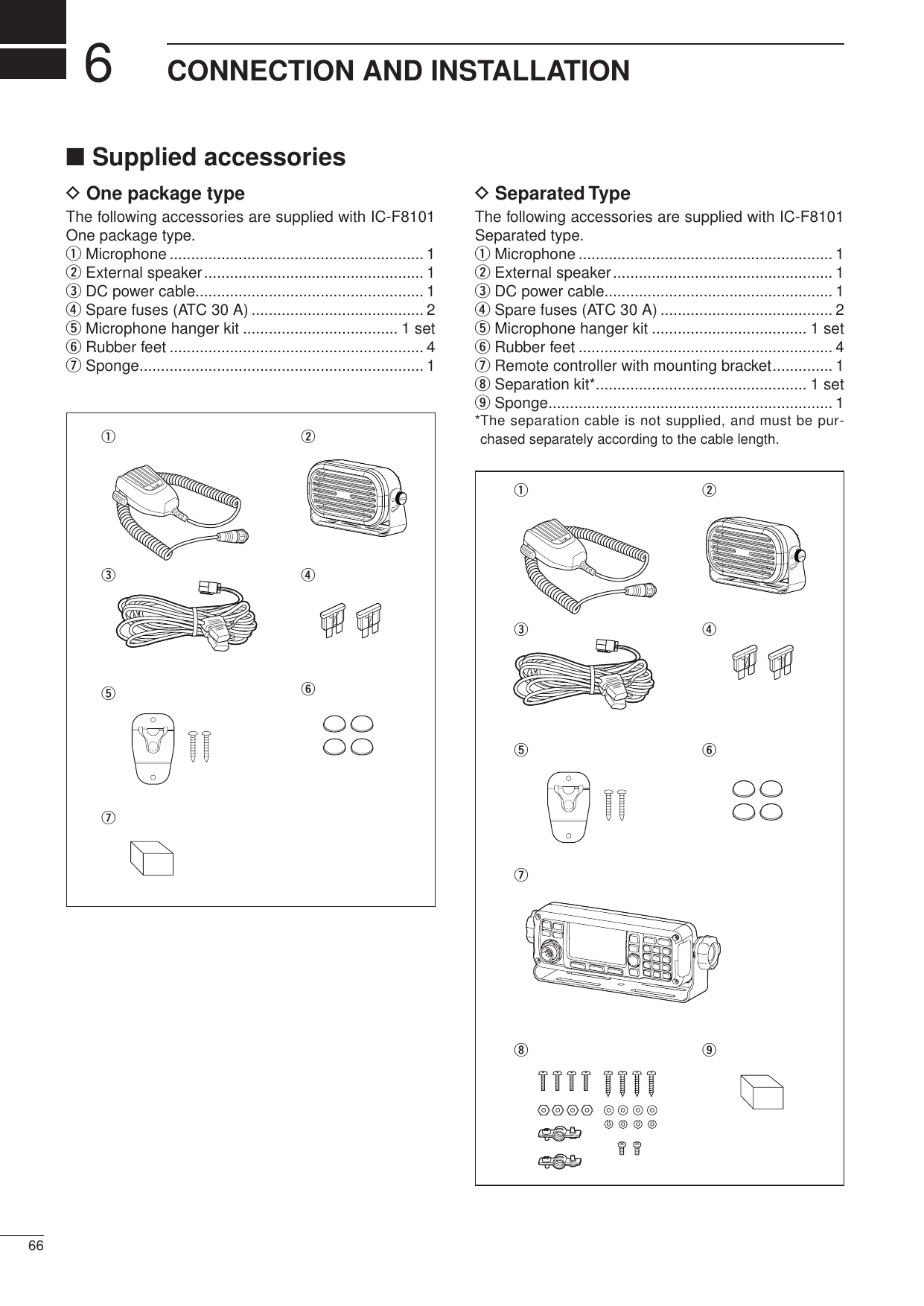
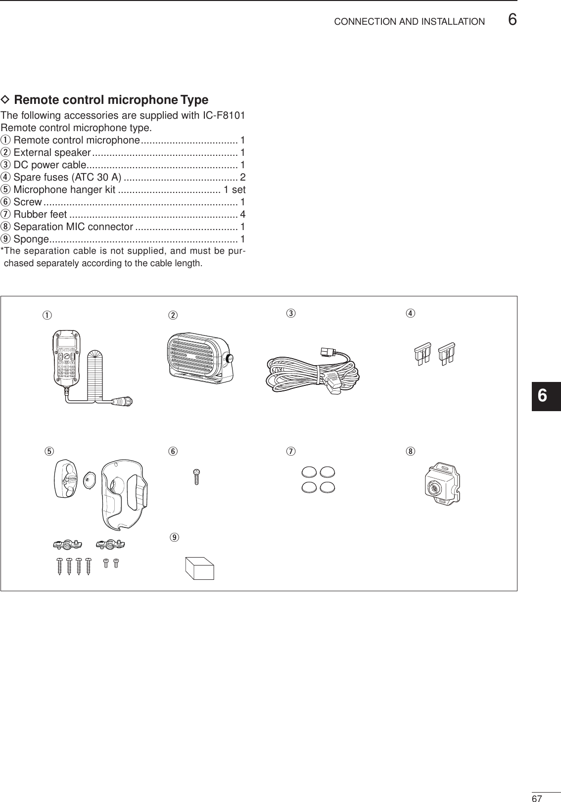
![686CONNECTION AND INSTALLATION2001 NEW 2001 NEW■ ConnectionsPCto [USB]to [ACC]to a USB portOPC-2308 GPS unitD-sub 9 pin(male)D-sub 9 pin(female)D-sub 15 pin(female)Modem unitto a 13.8 V DC power sourceTransceiverUSB cable(purchase separately)+ red_ black12VBattery12VBatteryR WARNING! NEVER remove the fuse holders from the black and red cables.NEVER remove this ferrite EMI filter.NEVER turn these connector screws.Only for USA versions R WARNING! NEVER connect to a 24 V bat-tery. This will damage the transceiver. Wrap both the antenna and the control cable con-nectors with rubber vulcanizing tape, and then wrap electrical tape over the rubber vulcanizing tape to help in waterproofing.1610511 1512to IC-F8101 SP connector AF inputFSK terminal unitAF groundTx/Rx controlTo pin 12To pin 10To pin 9• FSK connection[ACC]FSK keyingGround16511 15 To pin 12To pin 10• CW key connection[ACC]](https://usermanual.wiki/ICOM-orporated/350000/User-Guide-1993755-Page-74.png)
![2001 NEW696CONNECTION AND INSTALLATION1234567891011121314151617Quick ReferenceAT-140GroundIC-F8101 main unitto a 13.8 V DC power source to [ATU]OPC-2309 (10 m; 32.8 ft): 4 pinGround(see page 51)D-sub 9 pin(female)DO NOT stretch the Ground wire. This may cause a ground wire disconnection and/or damage. DO NOT pull the antenna and control cable re-ceptacles. This may cause a cable disconnection (in the tuner unit), inside connector damage or a bad connection. Wrap both the antenna and the control cable con-nectors with rubber vulcanizing tape, and then wrap electrical tape over the rubber vulcanizing tape to help in waterproofing.](https://usermanual.wiki/ICOM-orporated/350000/User-Guide-1993755-Page-75.png)
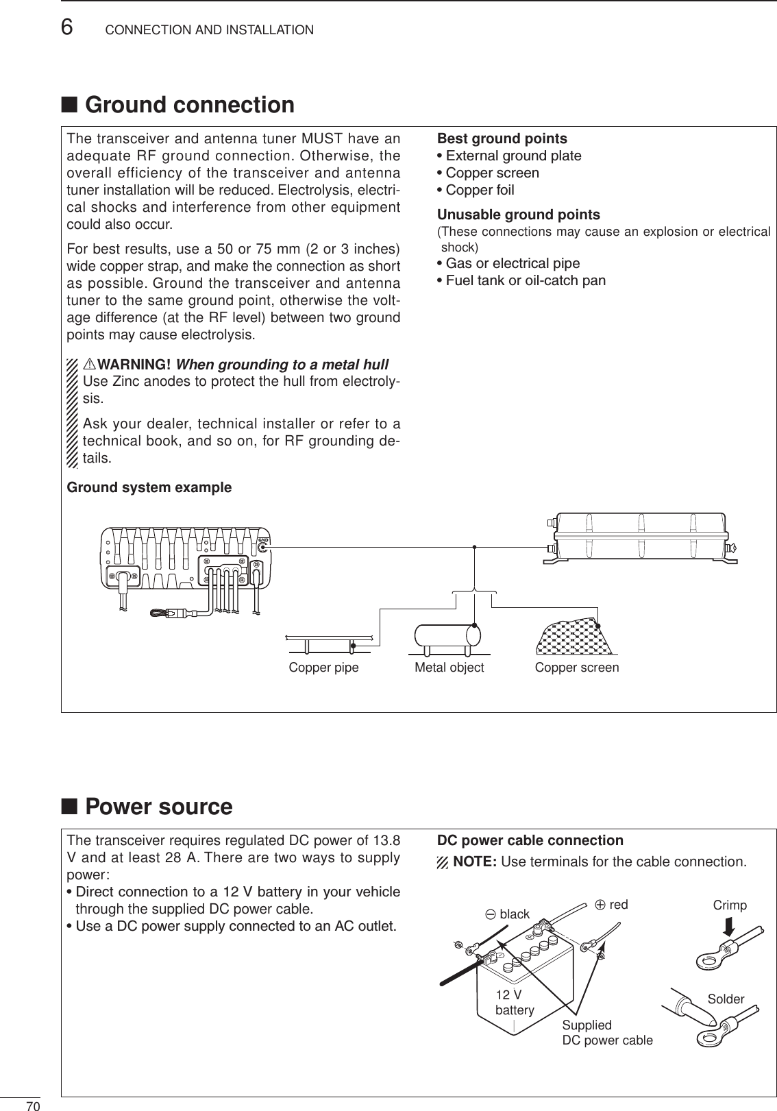
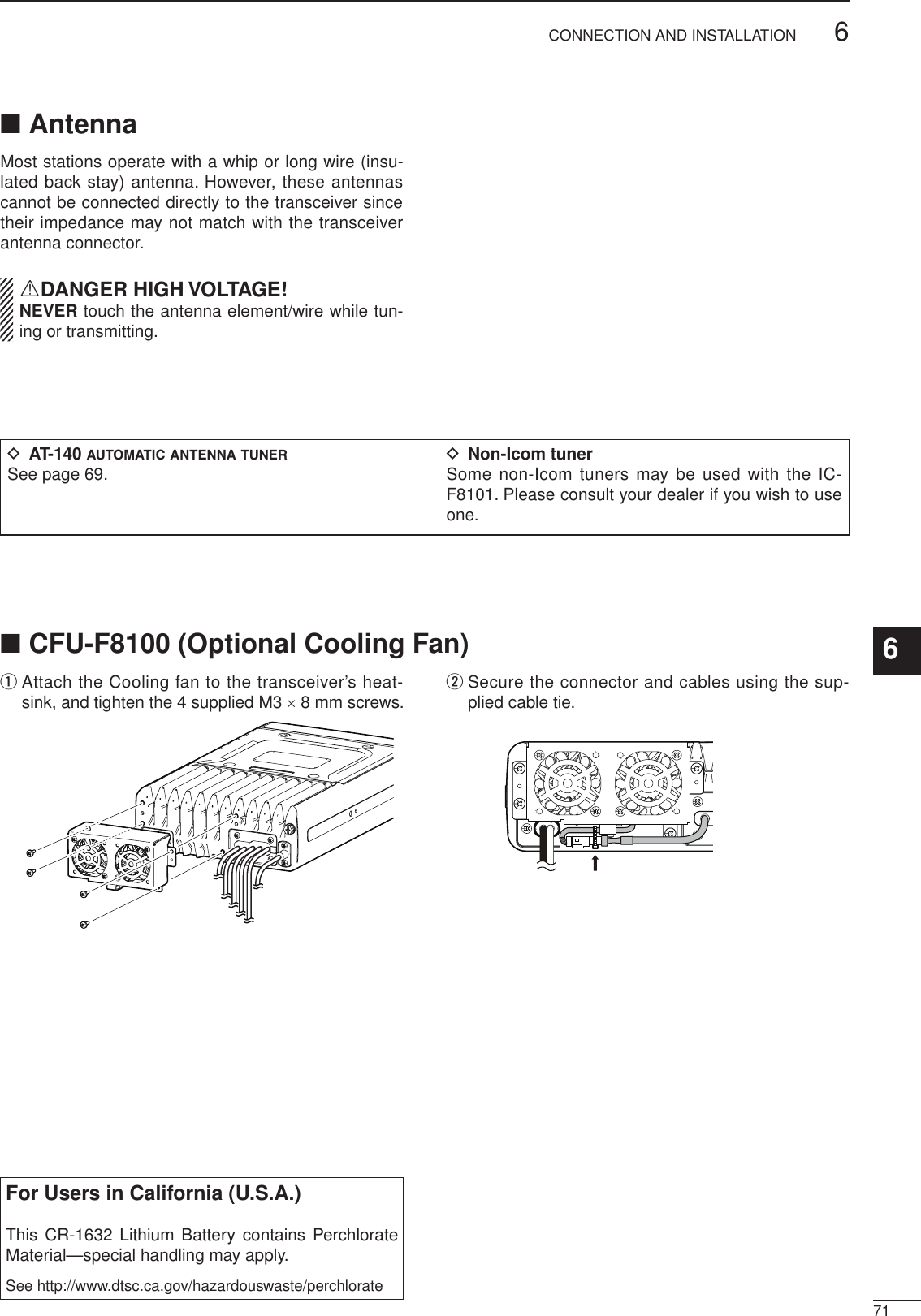
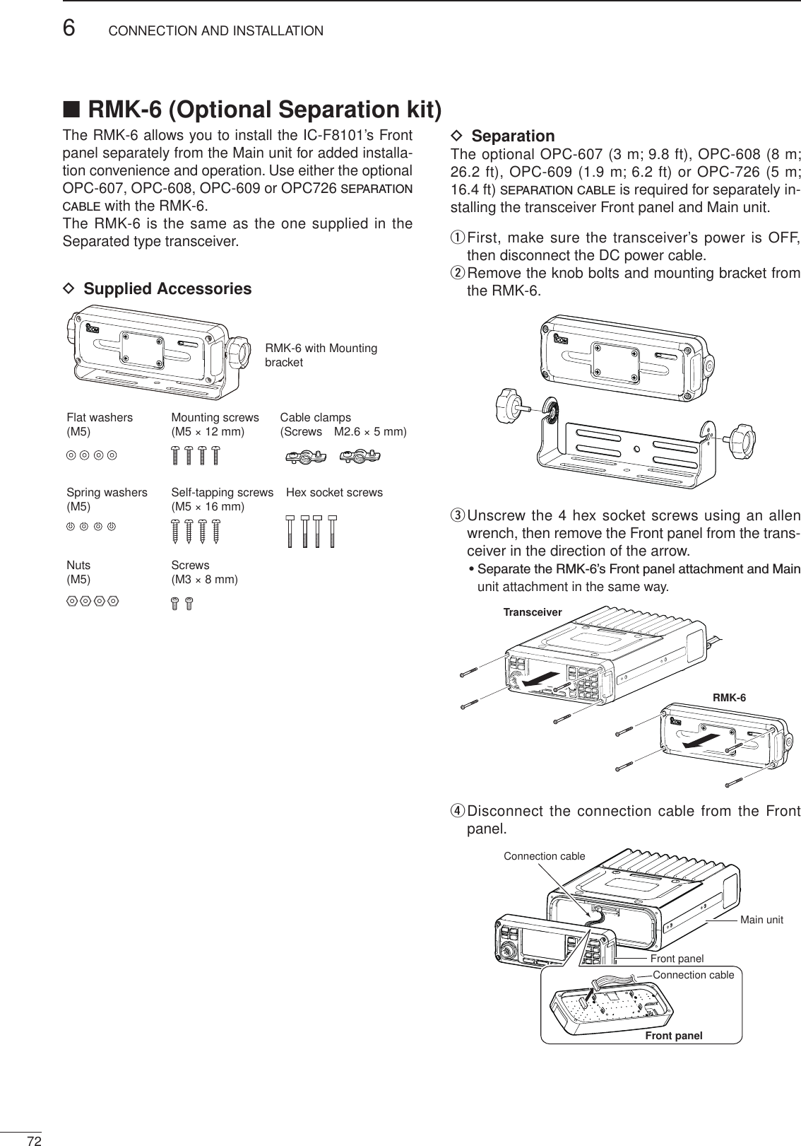
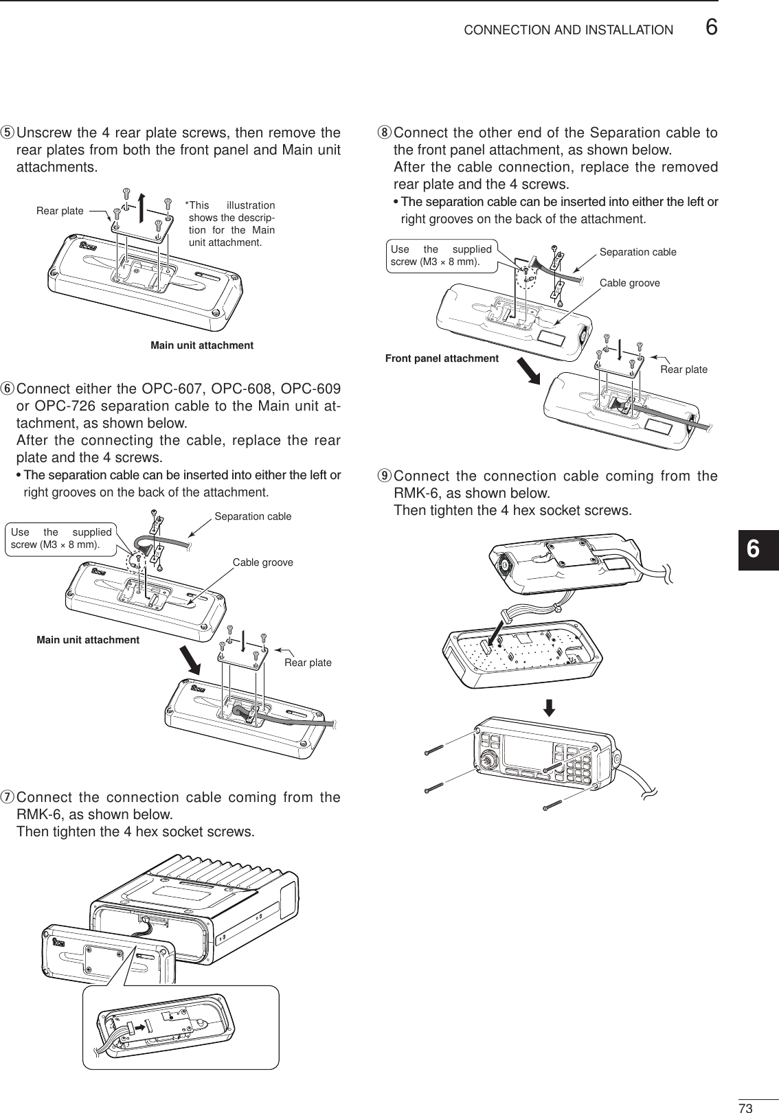
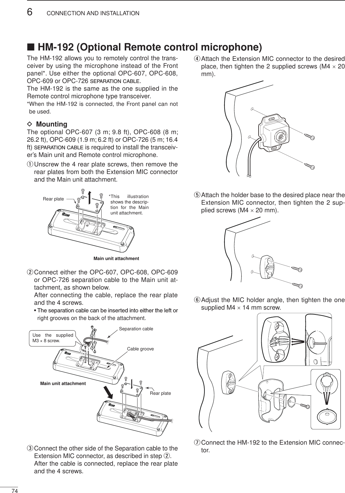
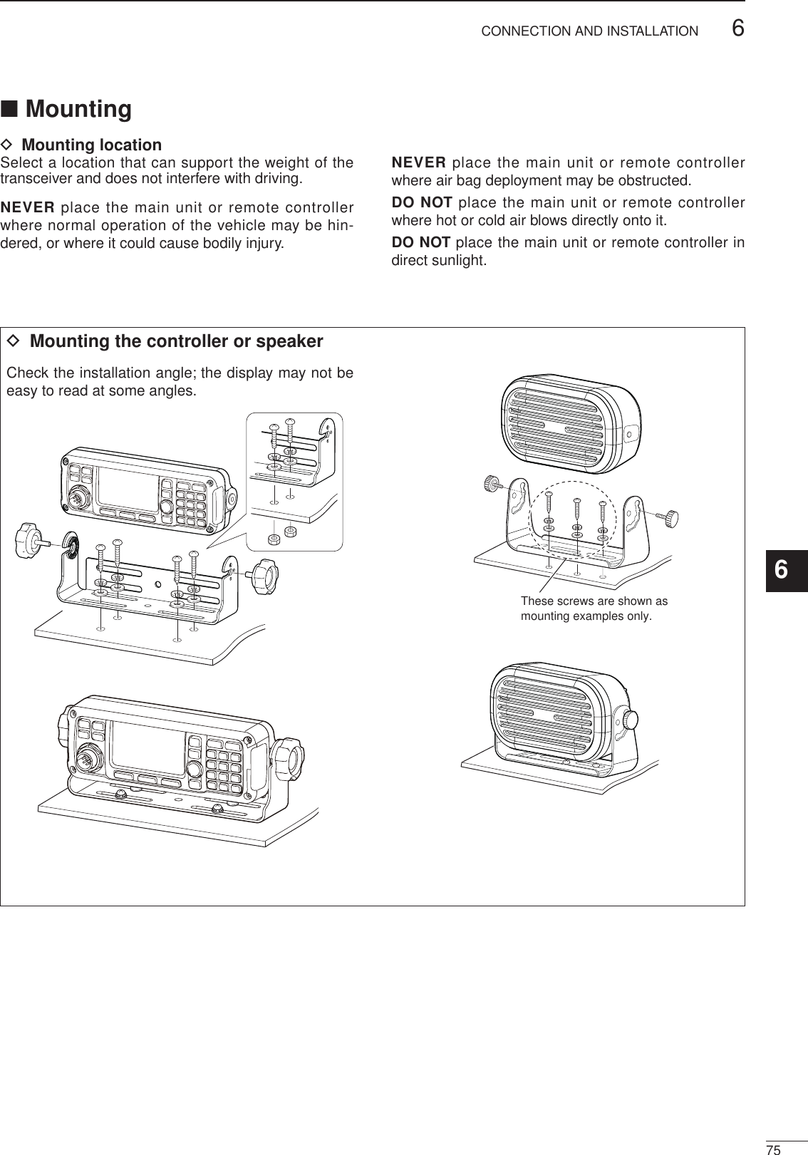
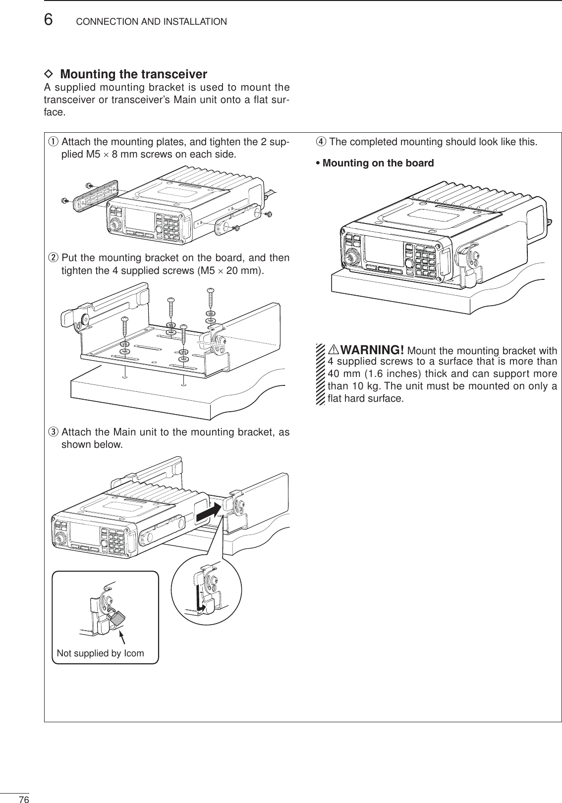
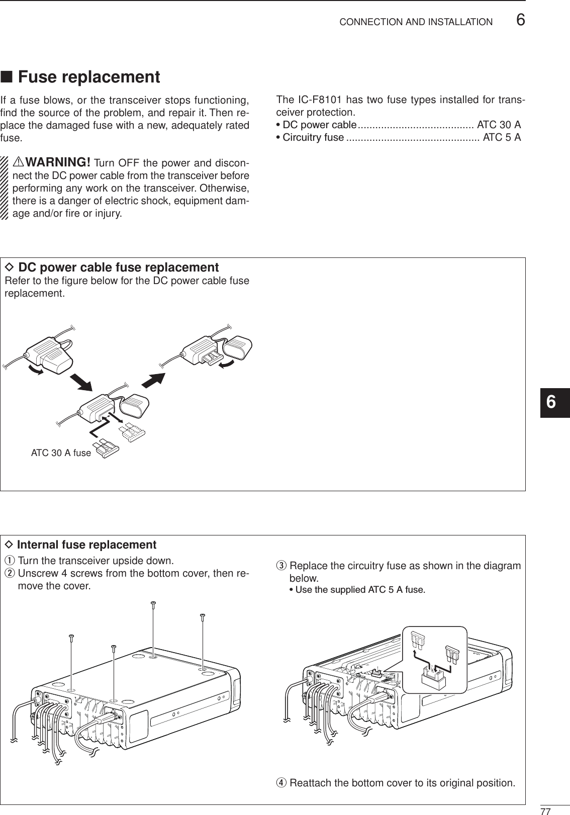
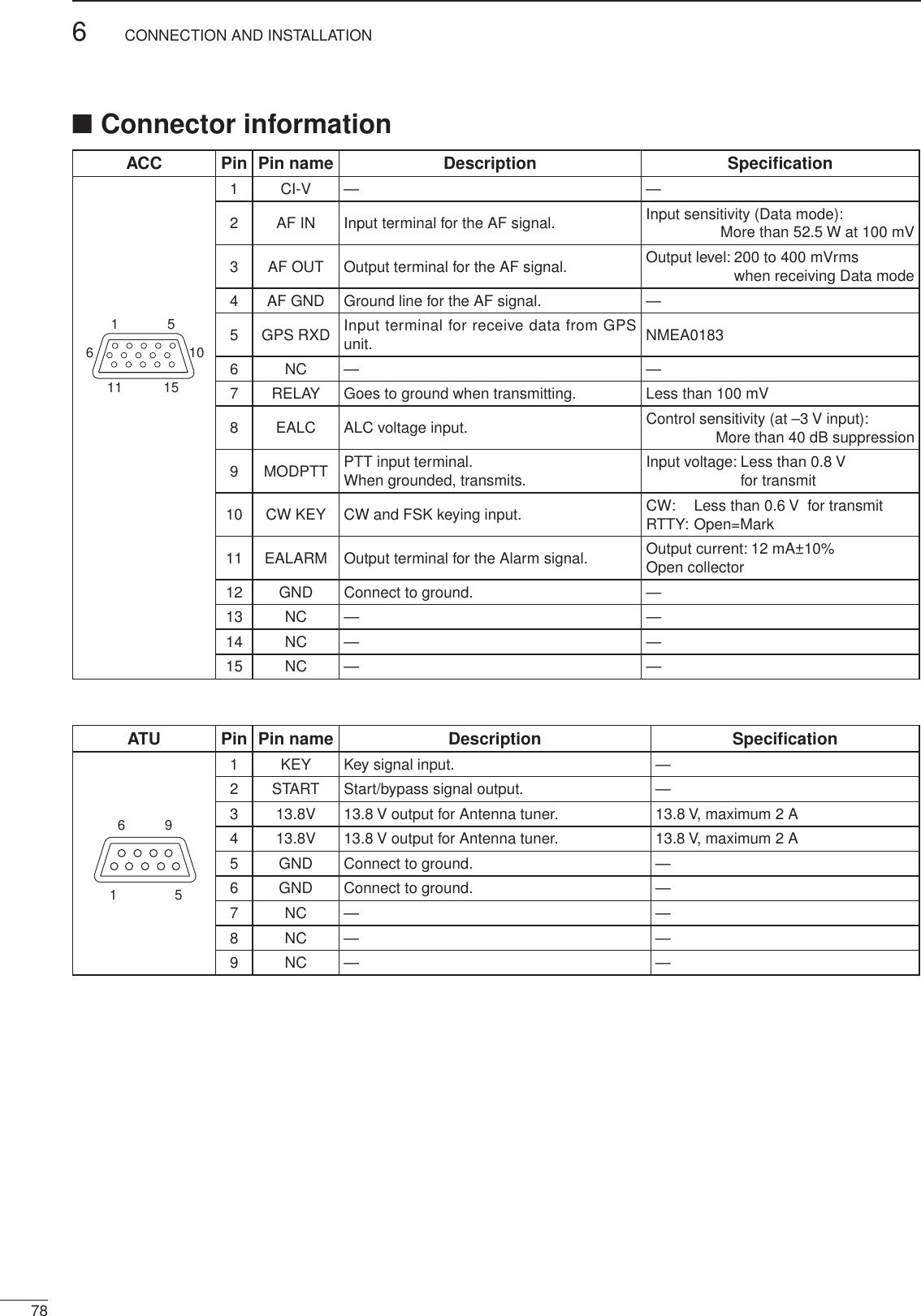
![796CONNECTION AND INSTALLATION1234567891011121314151617Quick ReferencePin Pin name Pin15691 NC —2 GPS RX 53 NC —4 NC —5 GND 126 NC —D-sub 9 pin(Male)7 NC —11 15165108 NC —9 NC —15691 CI-V 12 MODPTT 93 NC —4 NC —5 NC —6 AF OUT 3D-sub 9 pin(Female)7 AF IN 2 D-sub 15 pin(Male)8 AF GND 49 GND 12■Connector information for OPC-2308to IC-F8101 [ACC] OPC-2308D-sub 9 pin(male)D-sub 15 pin(male)D-sub 9 pin(female)](https://usermanual.wiki/ICOM-orporated/350000/User-Guide-1993755-Page-85.png)