ICOM orporated 350000 HF Transeiver User Manual
ICOM Incorporated HF Transeiver
User Manual

2001 NEW
HF TRANSCEIVER
iF8101
INSTRUCTION MANUAL
This device complies with Part 15 of the FCC
Rules. Operation is subject to the condition that
this device does not cause harmful interference.

i
2001 NEW 2001 NEW
FOREWORD
Thank you for purchasing this Icom product. The IC-
F8101 h f t r a n s c e i v e r is designed and built with
Icom’s state of the art technology and craftsmanship.
With proper care, this product should provide you with
years of trouble-free operation.
We appreciate you making the IC-F8101 your radio of
choice, and hope you agree with Icom’s philosophy of
“technology first.”
Many hours of research and develop-
ment went into the design of your IC-F8101.
D FEATURES
❍ ALE (Automatic Link Establishment)/Sel-
call capability
❍ Digital Signal Processor (DSP) allows flex-
ible filter selection
❍ Full-dot matrix LCD for a variety of infor-
mation
IMPORTANT
READ THIS INSTRUCTION MANUAL
CAREFULLY before attempting to operate the
transceiver.
SAVE THIS INSTRUCTION MANUAL. This
manual contains important safety and operating in-
structions for the IC-F8101.
EXPLICIT DEFINITIONS
WORD DEFINITION
R DANGER! Personal death, serious injury or an
explosion may occur.
R WARNING! Personal injury, fire hazard or electric
shock may occur.
CAUTION Equipment damage may occur.
NOTE Recommended for optimum use. No
risk of personal injury, fire or electric
shock.
Versions of the IC-F8101 which display
the “N33” symbol on the serial number
seal, comply with Standard Australia
Specification No. AS/NZS 4770: 2000.
Icom, Icom Inc. and the Icom logo are registered trademarks
of Icom Incorporated (Japan) in Japan, the United States,
the United Kingdom, Germany, France, Spain, Russia and/or
other countries.
All other products or brands are registered trademarks or
trademarks of their respective holders.
FCC INFORMATION
FOR CLASS A UNINTENTIONAL RADIATORS:
This equipment has been tested and found to comply
with the limits for a Class A digital device, pursuant to
part 15 of the FCC Rules. These limits are designed to
provide reasonable protection against harmful interfer-
ence when the equipment is operated in a commercial
environment. This equipment generates, uses, and
can radiate radio frequency energy and, if not installed
and used in accordance with the instruction manual,
may cause harmful interference to radio communica-
tions. Operation of this equipment in a residential area
is likely to cause harmful interference in which case
the user will be required to correct the interference at
his own expense.
CAUTION: Changes or modifications to this trans-
ceiver, not expressly approved by Icom Inc., could
void your authority to operate this transceiver under
FCC regulations.

2001 NEW
ii
FOREWORD .............................................................. i
IMPORTANT ............................................................... i
EXPLICIT DEFINITIONS ............................................ i
FCC INFORMATION .................................................. i
TABLE OF CONTENTS ..............................................ii
SAFETY TRAINING INFORMATION .........................iii
INFORMATION EN MATIÈRE DE SÉCURITÉ ..........iv
PRECAUTIONS ......................................................... v
1 PANEL DESCRIPTION ..................................... 1–6
Controller (Front panel or HM-192) ■ ................... 1
Rear panel ■ ........................................................ 4
LCD screen ■ ....................................................... 5
2 BASIC OPERATION ....................................... 7–10
Power ON ■ .......................................................... 7
Selecting the display mode ■ ............................... 7
Selecting a channel ■........................................... 8
Setting audio volume ■ ........................................ 8
Squelch function ■ ............................................... 8
Scan function ■ .................................................... 9
Mode selection ■ .................................................. 9
VFO operation ■ ................................................. 10
3 RECEIVE AND TRANSMIT ........................... 11–17
Basic voice transmit/receive ■ ............................ 11
Functions for transmit ■ ..................................... 12
Functions for receive ■ ....................................... 14
4 SELCALL/ALE OPERATION ........................ 18–32
Selcall/ALE ■...................................................... 18
5 MENU SCREEN ............................................ 33–65
Manager Menu ■ ................................................ 33
Main Menu ■ ...................................................... 46
CPU Reset ■ ...................................................... 65
6 CONNECTION AND INSTALLATION ........... 66–79
Supplied accessories ■ ...................................... 66
Connections ■ .................................................... 68
Ground connection ■.......................................... 70
Power source ■ .................................................. 70
Antenna ■........................................................... 71
CFU-F8100 (Optional Cooling Fan) ■ ................ 71
RMK-6 (Optional Separation kit) ■ ..................... 72
HM-192 (Optional Remote control microphone) ■
........................................................................ 74
Mounting ■ ......................................................... 75
Fuse replacement ■ ........................................... 77
Connector information ■ ..................................... 78
Connector information for OPC-2308 ■ ............. 79
7 SPECIFICATIONS ............................................... 80
8 OPTIONS ............................................................ 81
TABLE OF CONTENTS
1
2
3
4
5
6
7
8

iii
2001 NEW 2001 NEW
SAFETY TRAINING INFORMATION
WARNING
Your Icom radio generates RF electromag-
netic energy during transmit mode. This
radio is designed for and classified as “Oc-
cupational Use Only”, meaning it must be
used only during the course of employment
by individuals aware of the hazards, and the ways to
minimize such hazards. This radio is NOT intended for
use by the “General Population” in an uncontrolled en-
vironment.
• For compliance with FCC and IC RF Exposure Re-
quirements, the transmitter antenna installation shall
comply with the following two conditions:
1. The transmitter antenna gain shall not exceed
0 dBi.
2. The antenna is required to be located outside of
a vehicle and kept at a distance of 80 centime-
ters or more between the transmitting antenna of
this device and any persons during operation. For
small vehicle as worst case, the antenna shall be
located on the roof top at any place on the centre
line along the vehicle in order to achieve 80 cen-
timeters separation distance. In order to ensure
this distance is met, the installation of the antenna
must be mounted at least 80 centimeters away
from the nearest edge of the vehicle in order to
protect against exposure to bystanders.
3. Transmit only when people outside the vehicle are
at least the recommended minimum distance of
160 centimeters away from the properly installed
antenna. This separation distance will ensure that
there is sufficient distance from a properly installed
externally-mounted antenna to satisfy the RF ex-
posure requirements in the applicable RF exposure
compliance standards.
CAUTION
To ensure that your exposure to RF
electromagnetic energy is within the
FCC allowable limits for occupational
use, always adhere to the following
guidelines:
• DO NOT operate the radio without a proper antenna
attached, as this may damage the radio and may
also cause you to exceed FCC and IC RF exposure
limits. A proper antenna is the antenna supplied with
this radio by the manufacturer or an antenna specifi-
cally authorized by the manufacturer for use with this
radio.
• DO NOT transmit for more than 50% of total radio
use time (“50% duty cycle”). Transmitting more than
50% of the time can cause FCC and IC RF exposure
compliance requirements to be exceeded. The radio
is transmitting when the “TX” icon is displayed. You
can cause the radio to transmit by pressing the “PTT”
switch.
Electromagnetic Interference/Compatibility
During transmissions, your Icom radio generates RF
energy that can possibly cause interference with other
devices or systems. To avoid such interference, turn
OFF the radio in areas where signs are posted to do
so. DO NOT operate the transmitter in areas that are
sensitive to electromagnetic radiation such as hospi-
tals, aircraft, and blasting sites.

2001 NEW
iv
INFORMATION EN MATIÈRE DE SÉCURITÉ
AVERTISSEMENT
Votre radio Icom produit une énergie
électromagnétique de radiofréquen-
ces (RF), en mode de transmission.
Cette radio est conçue pour un
«usage professionnel seulement» et
classée comme tel, ce qui signifie qu’elle doit être
utilisée uniquement dans le cadre d’un travail par
des personnes conscientes des dangers et des
mesures visant à minimiser ces dangers. Elle
N’EST PAS conçue pour une «utilisation grand
public», dans un environnement non contrôlé.
• Afin de satisfaire aux exigences de la FCC et d’IC
en matière d’exposition aux RF, il est nécessaire
que l’antenne soit installée conformément aux trois
conditions suivantes:
1. Le gain de l’antenne du radio émetteur ne doit
pas dépasser 0dBi.
2. Il faut que l’antenne émettrice de cet appareil
soit placée à l’extérieur d’un véhicule et tenue
éloignée d’au moins 80 centimètres de toute per-
sonne pendant le fonctionnement. Dans le pire
des cas, pour un petit véhicule, l’antenne doit être
placée sur le toit, n’importe où dans l’axe central
du véhicule, afin de respecter une distance de 80
cm du bord le plus rapproché du véhicule et ainsi
éviter que les personnes présentes soient expo-
sées.
3. Émettre uniquement lorsque les personnes à
l’extérieur du véhicule se trouvent à au moins la
distance minimale recommandée de 160 cm de
l’antenne correctement installée. Cette distance
de sécurité assurera que les personnes soient
placées suffisamment loin d’une antenne correcte-
ment fixée à l’extérieur pour satisfaire aux exigen-
ces en matière d’exposition aux RF, en vertu des
normes de conformité applicables.
MISE EN GARDE
Afin de vous assurer que votre expo-
sition à une énergie électromagnéti-
que de RF se situe dans les limites
permises par la FCC pour une utili-
sation grand public, veuillez en tout
temps respecter les directives sui-
vantes:
• NE PAS faire fonctionner la radio sans qu’une
antenne appropriée y soit fixée, car ceci risque
d’endommager la radio et causer une exposition
supérieure aux limites établies par la FCC
et d’IC
.
L’antenne appropriée est celle qui est fournie avec
cette radio par le fabricant ou une antenne spécia-
lement autorisée par le fabricant pour être utilisée
avec cette radio.
• NE PAS émettre pendant plus de 50 % du temps
total d’utilisation de l’appareil («50 % du facteur
d’utilisation»). Émettre pendant plus de 50 % du
temps total d’utilisation peut causer une exposi-
tion aux RF supérieure aux limites établies par la
FCC et d’IC. La radio est en train d’émettre lors-
que le témoin du mode de transmission s’affiche
sur l’écran ACL. La radio émettra si vous appuyez
sur le bouton du microphone.
Interférence électromagnétique et compatibilité
En mode de transmission, votre radio Icom produit de
l’énergie de RF qui peut provoquer des interférences
avec d’autres appareils ou systèmes. Pour éviter de
telles interférences, mettez la radio hors tension dans
les secteurs où une signalisation l’exige. NE PAS faire
fonctionner l’émetteur dans des secteurs sensibles
au rayonnement électromagnétique tels que les hôpi-
taux, les aéronefs et les sites de dynamitage.

v
2001 NEW 2001 NEW
PRECAUTIONS
R DANGER HIGH RF VOLTAGE! NEVER attach
an antenna or internal antenna connector during trans-
mission. This may result in an electrical shock or burn.
R WARNING! NEVER operate the transceiver with a
headset or other audio accessories at high volume levels.
Hearing experts advise against continuous high volume
operation. If you experience a ringing in your ears, reduce
the volume or discontinue use.
R WARNING! NEVER operate or touch the trans-
ceiver with wet hands. This may result in an electric
shock or damage to the transceiver.
R WARNING! NEVER apply AC power to the
[DC13.8V] socket on the transceiver rear panel. This
could cause a fire or damage the transceiver.
R
WARNING! NEVER apply more than 16 V DC to the
[DC13.8V] socket on the transceiver rear panel, or use reverse
polarity. This could cause a fire or damage the transceiver.
R WARNING!
NEVER let metal, wire or other objects
protrude into the transceiver or into connectors on the
rear panel. This may result in an electric shock.
R WARNING! ALWAYS use the supplied Black and
red cables with fuse holders. After connecting the fuse
holders,
NEVER
cut the DC power cable between the
DC plug and fuse holder. If an incorrect connection is
made after cutting, the transceiver might be damaged.
R WARNING! Immediately turn OFF the transceiver
power and remove the power cable if it emits an abnor-
mal odor, sound or smoke. Contact your Icom dealer or
distributor for advice.
CAUTION: NEVER change the internal settings of the
transceiver. This may reduce transceiver performance
and/or damage to the transceiver.
In particular, incorrect settings for transmitter circuits,
such as output power, idling current, and so on, might
damage the expensive final devices.
The transceiver warranty does not cover any problems
caused by unauthorized internal adjustment.
CAUTION:
NEVER install the transceiver in a place
without adequate ventilation. Heat dissipation may be
reduced, and the transceiver may be damaged.
DO NOT use or place the transceiver in direct sunlight
or in areas with temperatures below –30°C (–22°F) or
above +60°C (+140°F).
The basic operations, transmission and reception of the
transceiver are guaranteed within the specified operat-
ing temperature range. However, the LCD display may
not be operate correctly, or show an indication in the
case of long hours of operation, or after being placed in
extremely cold areas.
DO NOT use harsh solvents such as benzine or alco-
hol when cleaning, as they will damage the transceiver
surfaces.
DO NOT push the PTT switch when you don’t actually
desire to transmit.
DO NOT place the transceiver against walls or putting
anything on top of the transceiver. This may overheat
the transceiver.
Always place unit in a secure place to avoid inadvertent
use by children.
BE CAREFUL! If you use a linear amplifier, set the
transceiver’s RF output power to less than the linear
amplifier’s maximum input level, otherwise, the linear
amplifier will be damaged.
BE CAREFUL! The transceiver will become hot when
operating the transceiver continuously for long periods
of time.
USE only the specified microphone. Other manufactur-
ers’ microphones have different pin assignments, and
connection to the IC-F8101 may damage the transceiver
or microphone.
During mobile operation, NEVER place the transceiver
where air bag deployment may be obstructed.
During mobile operation, DO NOT place the transceiver
where hot or cold air blows directly onto it.
During mobile operation, DO NOT operate the trans-
ceiver without running the vehicle’s engine. When the
transceiver’s power is ON and your vehicle’s engine is
OFF, the vehicle’s battery will soon become exhausted.
Make sure the transceiver power is OFF before starting
the vehicle engine. This will avoid possible damage to the
transceiver by ignition voltage spikes.
During maritime mobile operation, keep the trans-
ceiver and microphone as far away as possible from the
magnetic navigation compass to prevent erroneous indi-
cations.
Turn OFF the transceiver’s power and/or disconnect the
DC power cable when you will not use the transceiver
for long period of time.
KEEP the transceiver away from the heavy rain, and
Never immerse it in the water. The transceiver meets
IP54* requirements for dust-protection and splash resis-
tance.
However, once the transceiver has been dropped, dust-
protection and splash resistance cannot be guaranteed
due to the fact that the transceiver may be cracked, or
the waterproof seal damaged, and so on.
* Only when the supplied microphone is attached.
1
1
PANEL DESCRIPTION
2001 NEW
1
2
3
4
5
6
7
8
9
10
11
12
13
14
15
16
17
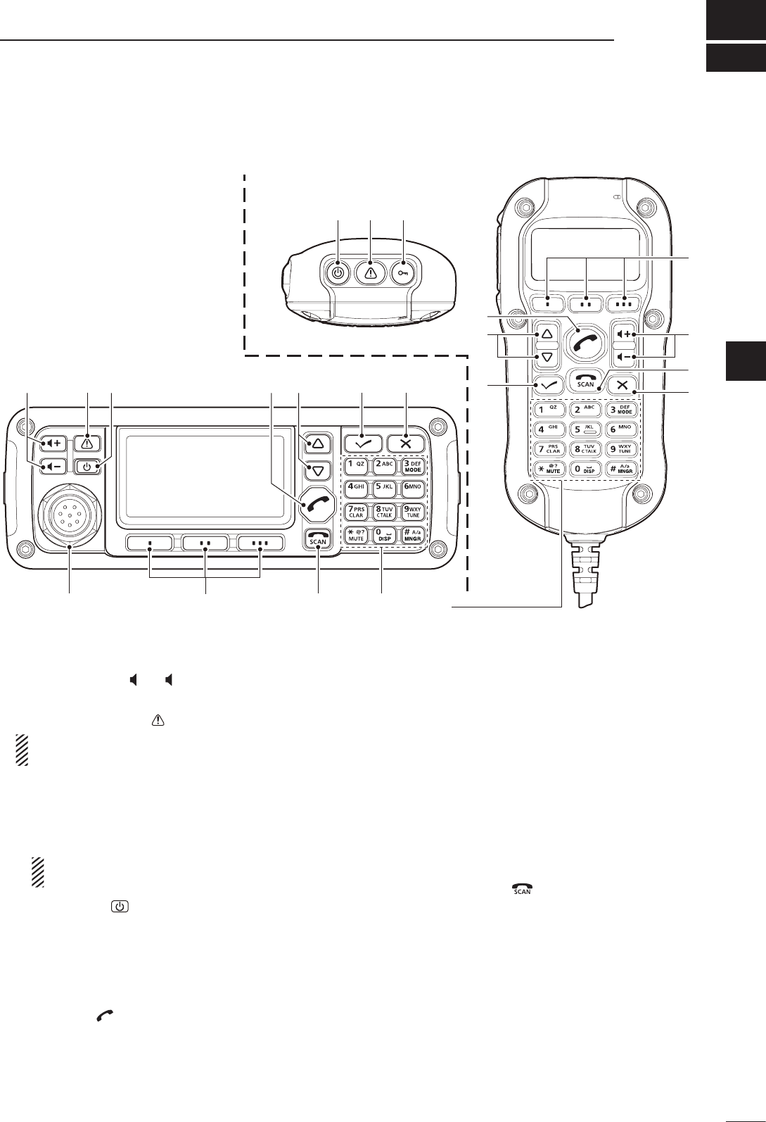
Quick Reference
q VOLUME KEYS [ +]/[ –] (p. 8)
Adjusts the audio output level.
w EMERGENCY KEY [ ]
NOTE: While in the VFO mode, the Emergency
key cannot be used.
➥ Push to enter the Emergency channel list.
• Push again to return to the normal operating screen.
➥ Hold down for 1 second to transmit Selcall and
RFDS (Royal Flying Doctor Service) calls to the
specified Selcall addresses in sequential order.
NOTE: RFDS calls are available in only the
Australian versions.
e POWER KEY [ ]
➥ When the transceiver’s power is OFF:
Push to turn ON the transceiver power.
• First, turn ON the DC power source.
➥ When the transceiver’s power is ON:
Hold down for 2 seconds to turn OFF the power.
r CALL KEY [ ]
Push to enter the Call menu.
• Push again to go to the next screen in the Call menu.
t UP/DOWN KEYS [r]/[s]
Selects the operating channel, the items in the
Menu mode, and so on.
y ENTER KEY [4]
Push to enter and exit the selected Menu in the ➥
Menu screen.
Hold down for 1 second to enter the program- ➥
ming mode.
u CLEAR KEY [8]
Push to enter or exit the Main Menu screen. ➥
Push to return to the previous screen. ➥
i CALL END/SCAN [ ]
Push to hang up or terminate a call. ➥
Push to start or stop a scan ➥
o FUNCTION KEYS [§]/[§§]/[§§§]
Push to select the function that is displayed above
each key on the LCD display.
• The functions vary, depending on the preprogramming
and selected menu.
q w
w !1e
er
io!0
tyu
Keypad (p. 2)
q
o
u
y
t
r
i
• HM-192
• Front panel
■ Controller (Front panel or HM-192)
•Common
Continued on the next page.
2
1PANEL DESCRIPTION
2001 NEW 2001 NEW
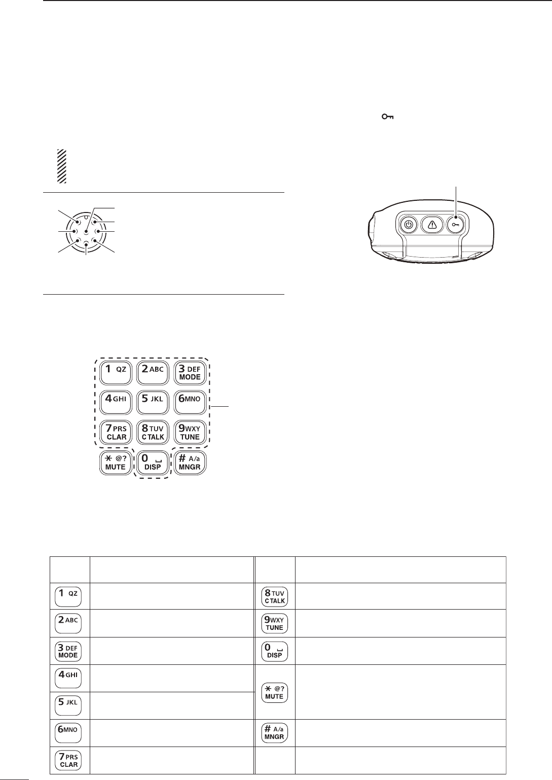
!0 MICROPHONE CONNECTOR [MIC]
Connects to only the microphone supplied with the
transceiver.
NOTE: NEVER connect the HM-192 or any other
microphone here. This could damage the trans-
ceiver and/or the microphone.
y
u
t
r
q
w
e
i
Front view
q MIC (microphone input)
w MIC SW1
e AF
r MIC SW2
t PTT
y GND
u GND (microphone ground)
i +8 V DC output (Max 10 mA)
!1 LOCK KEY [ ]
Hold down for 1 second to set the Key lock function
to ALL, NUMERIC KEY or OFF.
D Keypad
➥ Inputs numbers, characters or letters.
10-key
•Frontpanel •HM-192
•Selectablecharacters
KEY INPUT INPUTKEY
(space)
Upper/Lower case letters/Numbers
1 Q Z q z
2 A B C a b c
3 D E F d e f
4 G H I g h i
5 J K L j k l
6 M N O m n o
7 P R S p r s
8 T U V t u v
9 W X Y w x y
0
, . ; ? : ” ` ’ / ! @ # $ % ^ &
* ( ) _ – + = | \ ~ < > { } [ ]
Controller (Front panel or HM-192) (Continued) ■
!1

2001 NEW
3
1
PANEL DESCRIPTION
1
2
3
4
5
6
7
8
9
10
11
12
13
14
15
16
17
Quick Reference
MODE KEY [MODE]
Push to select the operating mode.
NOTE: The selectable operating mode can
be programmed in the “Mode” item of “Set-
mode.”
(Main Menu > Setmode > Mode) (pp. 56–60)
CLARIFIER KEY [CLAR]
Push to open the Clarifier adjustment win-
dow.
• Push [r] or [s] to adjust the frequency shift.
• Push this key again to close the window.
CLEAR TALK KEY [C TALK]
Push to turn the Clear Talk function ON or
OFF.
• The “C” icon appears when the function is ON.
TUNER KEY [TUNE]
Push to open the Antenna tune window.
(p. 11)
• Push [4] to start auto tuning.
• Push this key again to close the window.
DISPLAY KEY [DISP]
Push to select the display information.
• ‘Frequencies,’ ‘Latitude and Longitude,’ ‘Direction
and Elevation,’ ‘Antenna SWR and Power source
voltage’ and ‘Date and Time’ can be selected.
‘Latitude and Longitude’ and ‘Direction and El-
evation’ require data from a GPS unit.
MUTE KEY [MUTE]
Push to select the squelch type. Call squelch,
S-meter squelch (level 1 to 50), Voice squelch
or squelch OFF are selectable.
• The “S” icon appears when the Call squelch
function is ON.
NOTE: The Call squelch function cannot
be selected in the VFO mode.
• The “L” icon appears when the S-meter squelch
function is ON.
• The “V” icon appears when the Voice squelch
function is ON.
MANAGER KEY [MNGR]
Push to enter the Manager Menu screen.
4
1PANEL DESCRIPTION
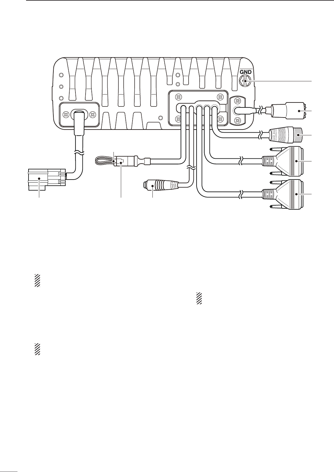
2001 NEW 2001 NEW
q DC POWER CONNECTOR [DC]
Accepts 13.8 V DC through a DC power cable.
w FAN CONNECTOR [FAN]
Connects to the optional CFU-F8100 Cooling Fan.
NOTE: Attach the protect plug when the optional
Cooling Fan is not used.
e SPEAKER JACK [SP]
Connects to an external speaker such as the sup-
plied SP-35/L.
r ACCESSORY CONNECTOR (9 PIN) [ATU]
Connects to the optional antenna tuner through the
OPC-2309 a n t e n n a t u n e r c a b l e .
NOTE: Attach the connector caps when the op-
tional cable is not connected.
t ACCESSORY CONNECTOR (15 PIN) [ACC]
Connects to a GPS unit or an external modem
through the optional OPC-2308 gps/extmod con-
n e c t i o n c a b l e .
When connecting a GPS unit, the transceiver sets
your position and time data in NMEA0183 version
3.xx format.
NOTE: Attach the connector caps when the op-
tional cable is not connected.
y USB CONNECTOR [USB]
Connects to a PC through an A-B type USB cable.
u ANTENNA CONNECTOR
Connects to a 50 Ω HF band antenna.
i GROUND TERMINAL
IMPORTANT! Connects to a solid ground point.
USB
ACC
GND
ANT
u
y
t
ATU
r
i
DC
qFAN
Protect plug
wSP
e
■ Rear panel

2001 NEW
5
1
PANEL DESCRIPTION
1
2
3
4
5
6
7
8
9
10
11
12
13
14
15
16
17
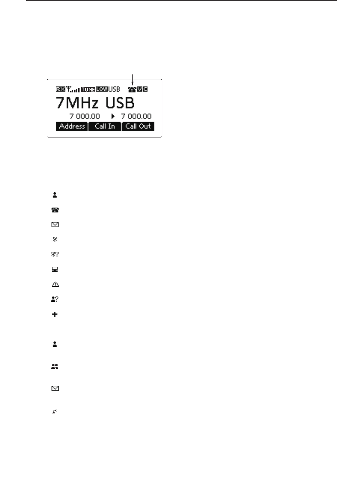
Quick Reference
q RECEIVE/TRANSMIT ICON
➥ “ RX” appears when signals are received or the
squelch is open.
➥ “ TX” appears when transmitting.
w S-METER/TX METERS
➥ Displays the receive signal strength.
➥ Displays the transmit output power.
e TUNE ICON
Appears after the automatic antenna tuner matches
the transceiver and antenna.
NOTE:
Appears only the frequency is set to within 10 Hz
of the tuned frequency.
r OUTPUT POWER ICON
➥ “HI” appears when high power is selected.
➥ “MID” appears when mid power is selected.
➥ “LOW” appears when low power is selected.
t OPERATING MODE INDICATOR
Displays the selected operating mode.
• “LSB,” “USB,” “CW,” “AM,” RTTY,” “LSBD1,” “USBD1,”
“LSBD2,” “USBD2,” “LSBD3” or “USBD3” appears, de-
pending on the operating mode.
Selectable operating modes differ depending on the
transceiver version and/or preprogramming.
y MUTE ICON
➥ “S” appears when the Call squelch function is se-
lected.
➥ “L” appears when the S-meter squelch is se-
lected.
➥ “V” appears when the Voice squelch is selected.
u CLEAR TALK ICON
Appears when the Clear Talk function is ON.
i MAIN READOUTS
<Memory Channel display>
Displays the channel name.
<VFO display>
Displays the operating frequency.
o SUB READOUTS
<Memory Channel display>
Displays the selected information.
• ‘Frequencies,’ ‘Latitude and Longitude,’ ‘Direction and El-
evation,’ ‘Antenna SWR and Power source voltage’ and
‘Date and Time’ can be displayed.
‘Latitude and Longitude’ and ‘Direction and Elevation’ re-
quire data from a GPS unit.
• When the frequencies are displayed, the receive fre-
quency is displayed on the right and the transmit fre-
quency is displayed on the left.
• “u” appears beside the receive or transmit frequencies,
and indicates which one is active.
• “p” or “q” appears instead of “u” to the right of the re-
ceive frequency, when the Clarifier function is ON, and it
indicates the upper or lower shift.
NOTE: No transmit frequency is displayed when
the selected channel is configured as “receive
only.”
<VFO display>
Shows the transmit or receive frequency when VFO
split is ON.
!0 FUNCTION DISPLAY
Displays the function of the [§], [§§] and [§§§] func-
tion keys.
!1 VFO ICON
<VFO display>
➥ “A” appears when VFO A is selected.
➥ “B” appears when VFO B is selected.
!2 CLARIFIER ICON
<VFO display>
“ p” or “q” appears when the Clarifier function is
ON, and indicates the upper or lower shift.
• Memory Channel Display • VFO Display
q w r t yu q w r t y ue e
!1
!3
!2
i
o
i
o
!0 !0
!2
■ LCD screen
Continued on the next page.
2001 NEW2001 NEW
6
1PANEL DESCRIPTION
2001 NEW
!3 CALL ICON
Displays the Call type icons for Selcall or ALE.
<Selcall>
• The “ ” icon blinks or appears when a Selective call is
transmitted or linked.
• The “ ” icon blinks or appears when a Phone call is
transmitted or linked.
• The “ ” icon blinks when a Message call is transmit-
ted.
• The “ ” icon blinks when a Send Position is transmit-
ted.
• The “ ” icon blinks when a Get Position call is trans-
mitted, or while waiting for its acknowledgement.
• The “ ” icon blinks when a Get Status call is transmit-
ted, or while waiting for its acknowledgement.
• The “ ” icon blinks or appears when an Emergency
call is transmitted or linked.
• The “ ” icon blinks when a Channel Test call is trans-
mitted or while waiting for its acknowledgement.
• The “ ” icon blinks or appears when an RFDS Emer-
gency call is transmitted or linked.
<ALE>
• The “ ” icon blinks when an Individual call is transmit-
ted or while waiting for its acknowledgement. The icon
stays ON when the call is linked.
• The “ ” icon blinks when a NET call is transmitted or
while waiting for its acknowledgement. The icon stays
on when the call is linked.
• The “ ” icon blinks when an AMD call is transmitted
or while waiting for its acknowledgement. The icon stays
ON when the call is linked.
• The “ ” icon blinks when a Sounding is transmitted.
• Memory Channel Display
!3
LCD screen (Continued) ■
2001 NEW
2
7
BASIC OPERATION
2001 NEW
1
2
3
4
5
6
7
8
9
10
11
12
13
14
15
16
17
Quick Reference
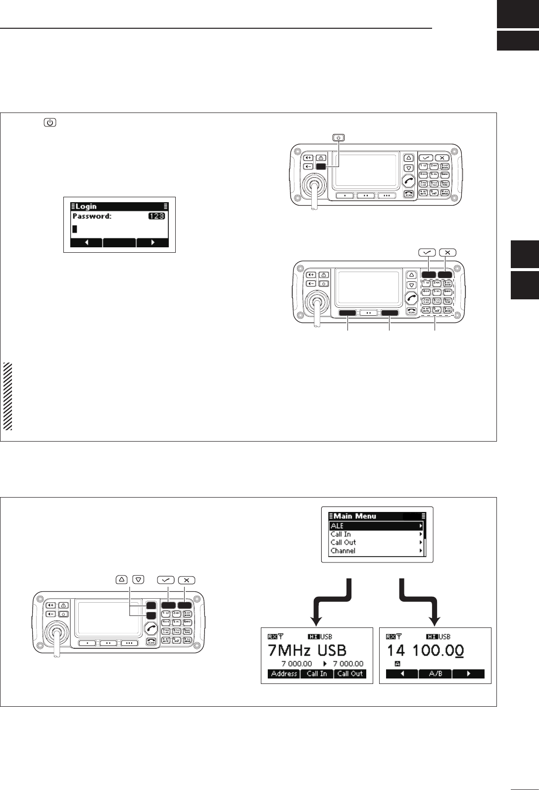
Push q[ ] to turn ON the Power.
• If the “Built-in Test Display” item of “Setmode” is set to
ON, ‘Built in Test’ appears.
(Main Menu > Setmode > Config)
• If the “User” item of “Setmode” is programmed, “Login”
appears.
(Main Menu > Setmode > Password)
Push the keypad keys to enter either the User w
password or Administrator password, and then
push [4].
• Repeatedly push [A/a](#) to select the character group,
ABC (upper case letters), abc (lower case letters) or
123 (numbers).
• Push [8] to delete a character.
• Push [t](§) or [u](§§§) to move the cursor.
NOTE:
• If you want to change any settings, you must be in
the Administrator mode.
• You can log into the Administrator mode with the
“Admin Login” item in the Manager Menu screen
(p. 34).
[][]Keypad
Power ON ■
Push q[8] to enter the Main Menu screen.
Push w[r] or [s] to select “Channel” or “VFO,” and
then push [4].
• If “Channel” is selected, the Memory Channel display
appears.
• If “VFO” is selected, the VFO display appears.
/
Selecting the display mode ■
Memory channel display VFO display
Main Menu screen
8
2BASIC OPERATION
2001 NEW 2001 NEW
The squelch function detects signals with voice com-
ponents and mutes unwanted signals. This provides
quiet stand-by.
When you need to receive weak signals, the squelch
can be turned OFF.
Push ➥[MUTE](M) one or more times to select a
squelch type.
• Selectable types are Call SQL, S-meter SQL (level 0 to
50), Voice SQL and OFF.
• The S-meter squelch level can be adjusted by the “Me-
ter Squelch Level” item of “Setmode.”
(Main Menu > Setmode > Config)
Mute icon
• The Mute icon, “S,” “L” or “V,” appears when the
squelch function, Call SQL, S-meter SQL or Voice SQL
is turned ON.
NOTE: The Call squelch function cannot be se-
lected in the VFO mode.
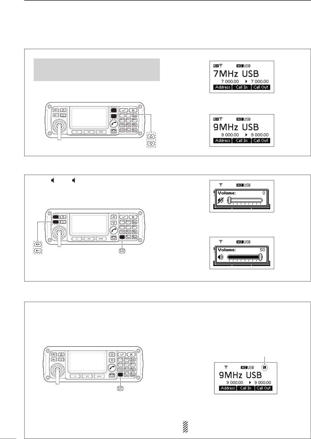
➥ Push [ +] or [ –] to adjust the audio level.
• If the squelch is closed, push [MUTE](M) one or more
times to open the squelch.
• The display shows the volume level while adjusting.
Minimum audio level
•
•
•
Maximum audio level
■ Squelch function
■ Setting audio volume
Select the Memory Channel Display. q
q Push [8] to enter the Main Menu screen.
w Push [r] or [s] to select “Channel,” and then
push [4].
Push w[r] or [s] to select a desired memory chan-
nel. •
•
•
■ Selecting a channel
2001 NEW
9
2
BASIC OPERATION
1
2
3
4
5
6
7
8
9
10
11
12
13
14
15
16
17
Quick Reference
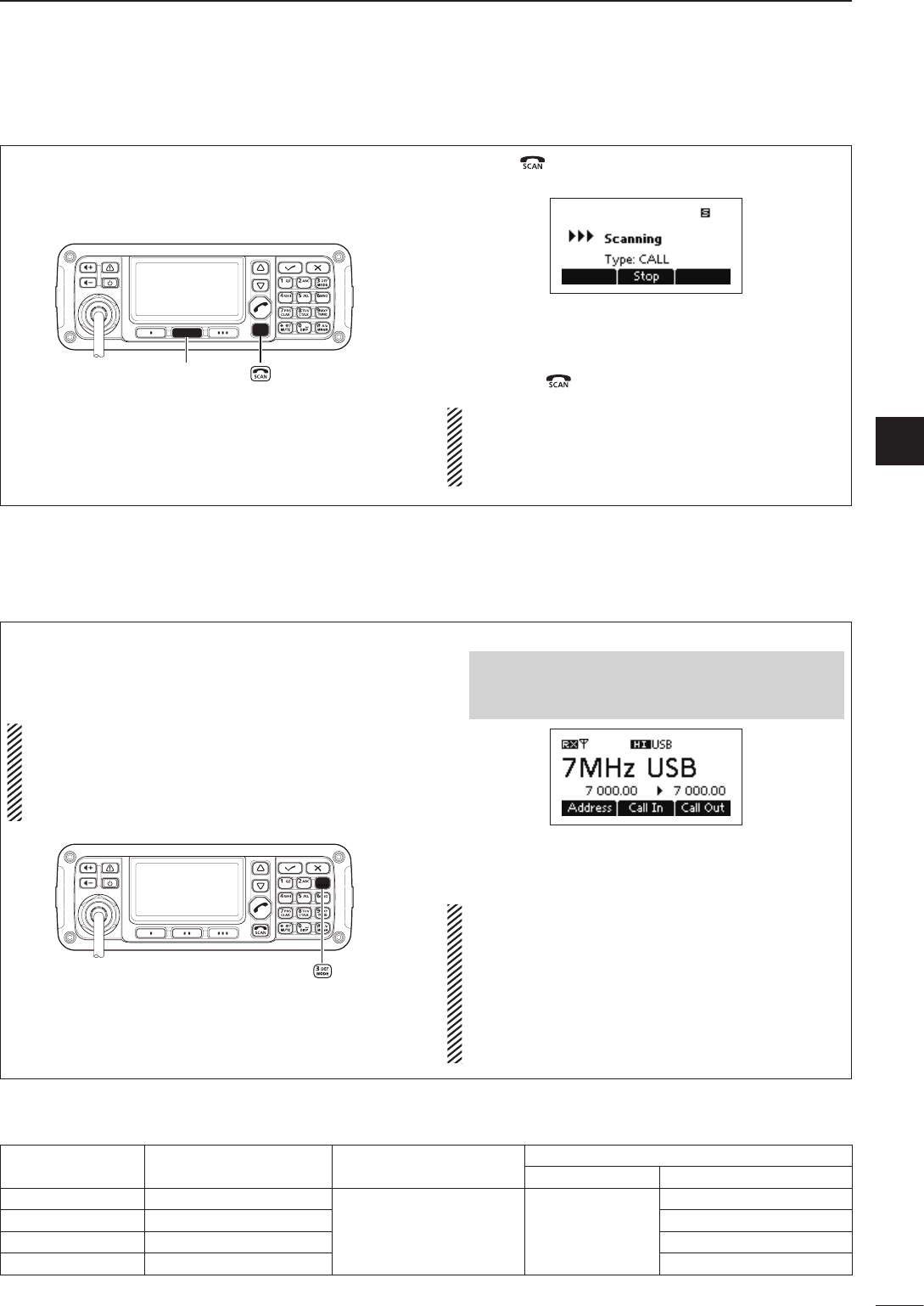
The scan function repeatedly scans programmed
channels. This function is convenient to check for
calls on multiple channels.
[Stop]
q Push [ ] to start a scan.
• “Scanning” and the Scan type are displayed.
w When a signal is received, the scan pauses on
that channel.
e Push [Stop](§§) to cancel the scan.
• Pushing [ ] also cancels the scan.
NOTE: The scan resume setting, the action after
receiving a signal, can be changed by the “Voice
Scan Resume” item of “Setmode.”
(Main Menu > Setmode > Config)
■ Scan function
The following modes are selectable in the IC-F8101:
LSB, USB, CW, AM, RTTY, LSBD1/2/3 and
USBD1/2/3.
NOTE: Only the preprogrammed operating modes
are selectable.
The selectable operating mode can be changed in
the “Mode” item of “Setmode.”
(Main Menu > Setmode)
Select the Display mode. q
q Push [8] to enter the Main Menu screen.
w Push [r] or [s] to select “Channel” or “VFO,”
and then push [4].
w Push [Mode](3) one or more times to select the
desired mode.
• The selected mode icon appears at the top of the display.
NOTE:
• On the Memory Channel display, the selected
operating mode can be used only temporarily.
When the channel is changed, the transceiver
returns to the preprogrammed operating mode.
• Depending on the transceiver version or prepro-
gramming, some operating modes may not be
selectable or usable except in receive.
■ Mode selection
For your reference D
Mode TX/RX offset frequency
[Hz] RX filter band width
[Hz]
Modulation input
MIC PTT ON MODEM PTT ON
LSB, USB 1500 (Fixed)
100 to 3000 (100Hz step) MIC
TC4, ACC, USB
LSBD1, USBD1 1500, 1650, 1800 TC4, ACC, USB
LSBD2, USBD2 1500, 1650, 1800 TC4, ACC, USB
LSBD3, USBD3 1500, 1650, 1800 TC4, ACC, USB
Default settings are shown in bold.
2001 NEW
10
2BASIC OPERATION
2001 NEW
In the VFO mode, you can set a desired operating fre-
quency, operating mode or split frequency function.
NOTE:
• The VFO mode operation can be disabled by the
“VFO Mode” item of “Setmode.”
(Main Menu > Setmode > Config)
•While in the VFO mode, the Selcall, ALE features,
Scan function or the Emergency key cannot be
used.
•EnteringtheVFOmode
Push q[8] to enter the Main Menu screen.
Push w[r] or [s] to select “VFO,” and then push
[4].
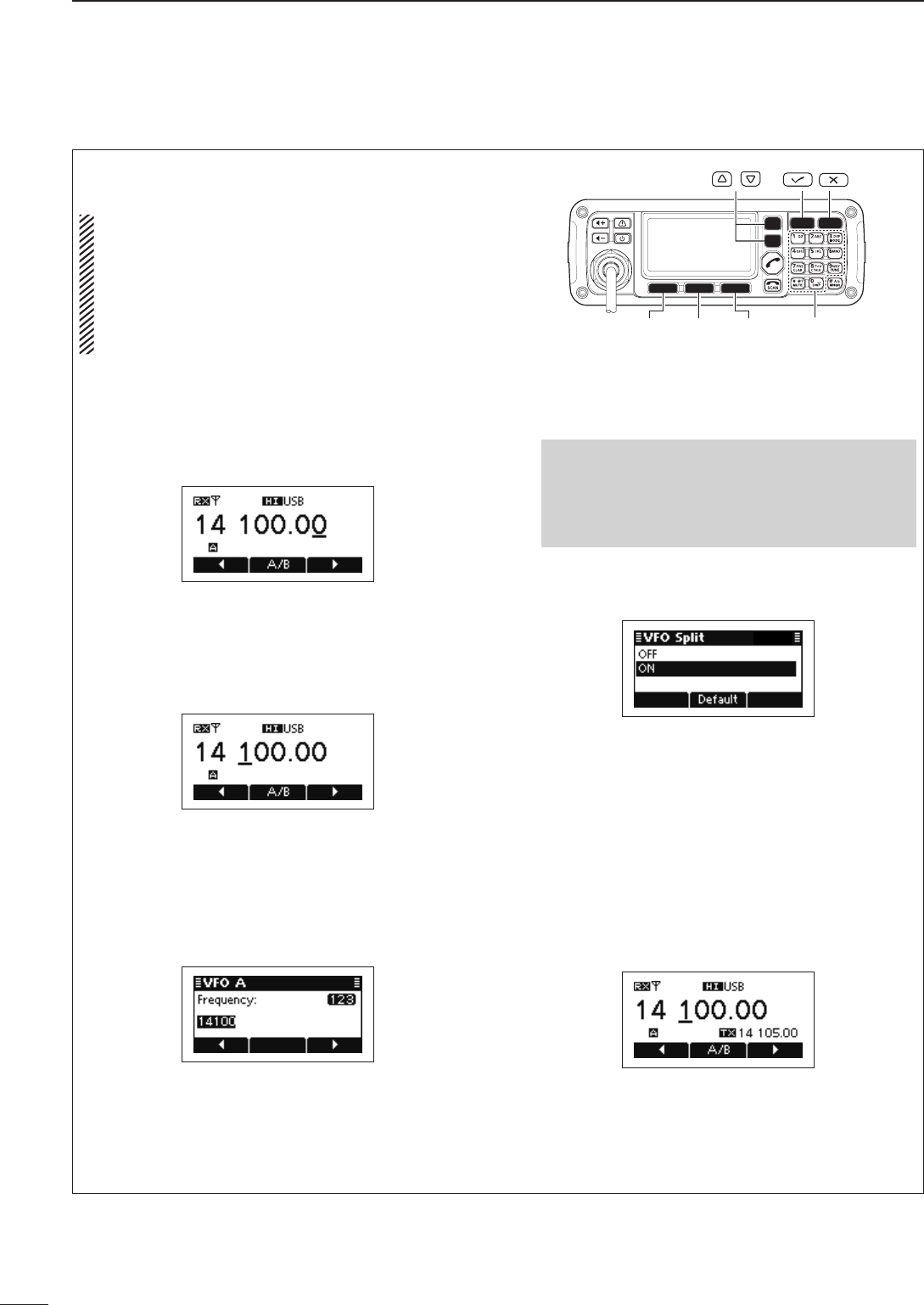
•Frequencysetting
Push q[A/B](§§) to select VFO A or VFO B.
Push w[t](§) or [u](§§§) to move the cursor to se-
lect the desired digit to be changed.
• The cursor is displayed below the selected digit
.
Push e[r] or [s] to change the digit.
•Directfrequencysetting
Push q[A/B](§§) to select VFO A or VFO B.
Hold down w[4] for 1 second to enter the direct fre-
quency input mode.
• The previously entered frequency blinks.
Push the keypad to enter the desired frequency. e
• Push [M] to enter the decimal point.
• Push [8] to delete the number.
• Push [t](§) or [u](§§§) to move the cursor.
Push r[4] to save the frequency and exit.
[��][���][�]
/
Keypad
•TurningONtheSplitfrequencyfunction
Push q[8] to enter the Main Menu screen.
Select the “VFO Split” item of “Setmode.” w
q Push [r] or [s] to select the item, and then
push [4] to open the screen.
(Setmode > Config)
w Push [r] or [s] to select “VFO Split,” and then
hold down [4] for 1 second.
Push e[r] or [s] to turn ON the function.
• If desired, hold down [Default](§§) for 1 second to re-
turn to the default setting
.
Push r[4] to save the setting, and return to the pre-
vious screen.
Push t[8] one or more times to exit the Main Menu
screen.
Enter the VFO mode. (See details to the left.) y
Push u[A/B](§§) to select VFO A or VFO B, and sep-
arately set the receive and transmit frequencies.
• The TX frequency appears below the RX frequency
.
• Push [A/B](§§) changes the VFOs between transmit
and receive.
• Hold down [A/B](§§) for 1 second to equalize the trans-
mit frequency to the receive frequency.
• To turn OFF the Split frequency function, set the “VFO
Split” item of “Setmode.” to “OFF.”
(Main Menu > Setmode > Config)
■ VFO operation
3
11
RECEIVE AND TRANSMIT
2001 NEW
1
2
3
4
5
6
7
8
9
10
11
12
13
14
15
16
17
Quick Reference
Basic voice transmit/receive ■
q First, check the following.
➥ The microphone and external speaker are con-
nected.
➥ No “S,” “L” or “V” mute icon appears.
• If “S,” “L” or “V” appears, push [MUTE](M) one or
more times to turn OFF the mute.
Mute icon
w Push
[
r
] or [
s
] to select the desired receive chan-
nel.
•
The S-meter shows the signal strength when a signal is
received.
e Push [+] or [–] to adjust the desired audio
level when receiving a signal.
• If the bass or treble of the receive audio is too strong,
push [CLAR](7) to set “Clarifier” to ON, and adjust to
obtain clear audio. (See page 14 for the Clarifier func-
tion details.)
• If the audio is distorted, select the suitable operating
mode. (See page 9 for the Mode selection details.)
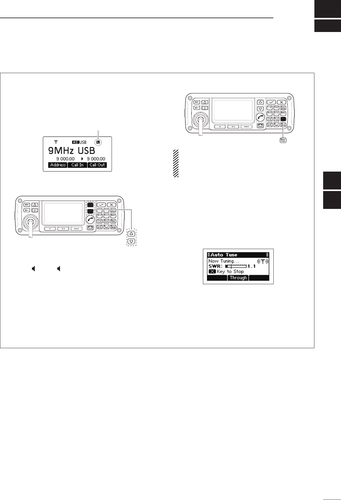
r Push [TUNE](9) to enter the antenna tune mode.
• The “Auto Tune” screen appears.
NOTE:
The antenna tune mode must be set to ON by
the “Tuner” item of “Setmode.” (Default: ON)
(Main Menu > Setmode > Config)
Push t[4] to start auto tuning.
• The display shows the antenna SWR.
• If the antenna cannot be tuned after 20 seconds, the
tuning circuit is automatically bypassed.
• After tuning is nished, the auto tune automatically
stops transmitting.
• If necessary, push [8] to manually stop transmitting.
• Push [Through](§§) to turn OFF the antenna tuner.
After tuning is finished, push y[TUNE](9) again to
return to the normal operating screen.
To transmit on the channel, hold down u[PTT] on the
microphone, and speak at a normal voice level.
• The RF meter shows the output power.
Release i[PTT] to receive.
Functions for transmit ■
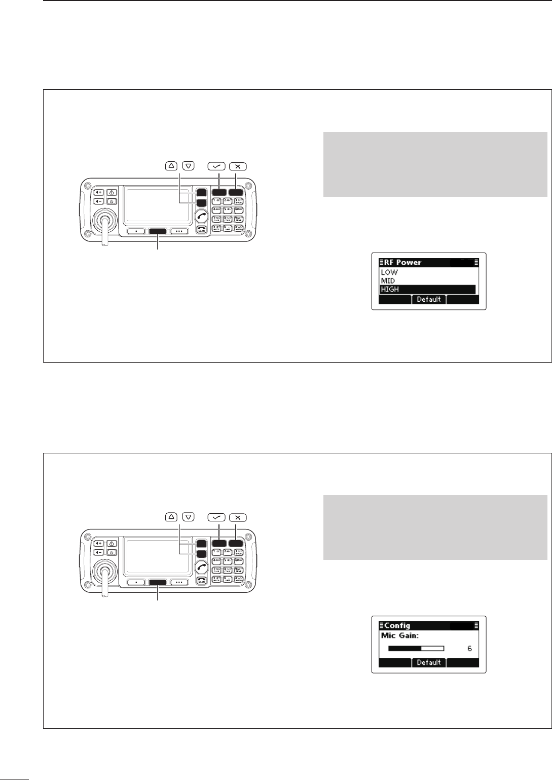
Transmit power selection D
The transceiver has three output power levels, HIGH,
MID and LOW. High power provides longer distance
communications and low power reduces power con-
sumption.
[Default]
/
Push q[8] to enter the Main Menu screen.
Select the “RF Power” item of “Setmode.” w
q Push [r] or [s] to select the item, and then
push [4] to open the screen.
(Setmode > Config)
w Push [r] or [s] to select “RF power,” and then
hold down [4] for 1 second.
Push e[r] or [s] to select the desired option, LOW,
MID or HIGH.
• If desired, hold down [Default](§§) for 1 second to re-
turn to the default setting
.
Push r[4] to save the setting, and return to the pre-
vious screen.
Push t[8] one or more times to exit.
Setting Microphone gain D
The microphone gain must be properly adjusted so
that your signal is not distorted when transmitted.
[Default]
/
Push q[8] to enter the Main Menu screen.
Select the “Mic Gain” item of “Setmode.” w
q Push [r] or [s] to select the item, and then
push [4] to open the screen.
(Setmode > Config)
w Push [r] or [s] to select “Mic Gain,” and then
hold down [4] for 1 second.
Push e[r] or [s] to adjust the desired setting level
to between 0 and 10.
• If desired, hold down [Default](§§) for 1 second to re-
turn to the default setting
.
Push r[4] to save the setting, and return to the pre-
vious screen.
Push t[8] one or more times to exit.
12
3RECEIVE AND TRANSMIT
2001 NEW 2001 NEW
13
3
RECEIVE AND TRANSMIT
3
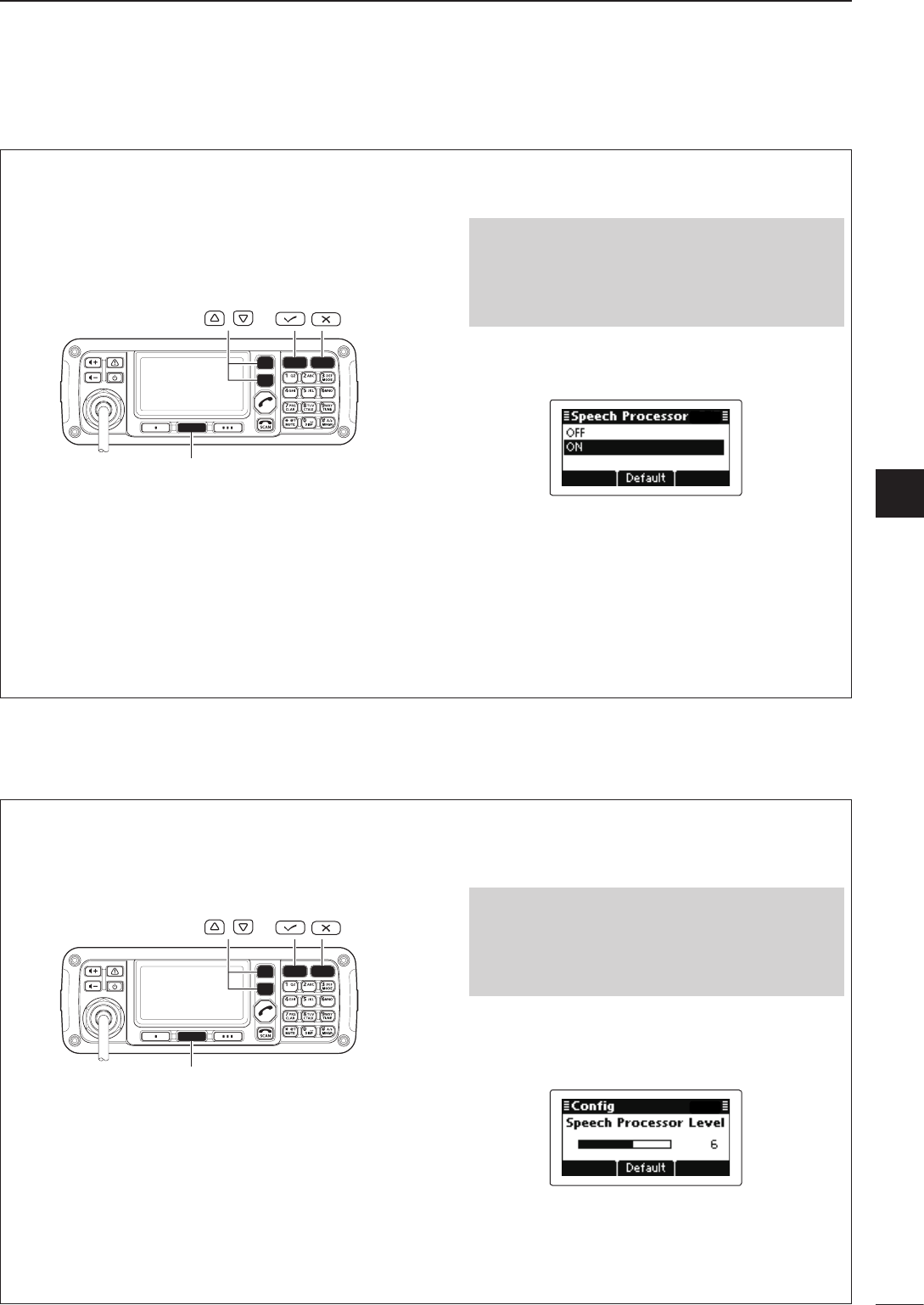
Speech Processor D
The IC-F8101 has a built-in, low distortion Speech
Processor circuit. This circuit increases your average
talk power in the SSB mode, and is especially useful
when the receiving station is having difficulty hearing
your audio.
[Default]
/
Push q[8] to enter the Main Menu screen.
Select the “Speech Processor” item of “Setmode.” w
q Push [r] or [s] to select the item, and then
push [4] to open the screen.
(Setmode > Config)
w Push [r] or [s] to select “Speech Processor,”
and then hold down [4] for 1 second.
Push e[r] or [s] to turn ON the function.
• If desired, hold down [Default](§§) for 1 second to re-
turn to the default setting
.
Push r[4] to save the setting, and return to the pre-
vious screen.
• If desired, adjust the Speech Processor Level. See the
next topic for details
.
Push t[8] one or more times to exit.
Push y[MODE](3) one or more times to select the
USB or LSB mode.
Hold down u[PTT] on the microphone, and speak at
a normal voice level.
Speech Processor Level D
The Speech Processor level must be properly adjust-
ed so that your signal is not distorted when transmit-
ted.
[Default]
/
Push q[8] to enter the Main Menu screen.
Select the “Speech Processor Level” item of “Set- w
mode.”
q Push [r] or [s] to select the item, and then
push [4] to open the screen.
(Setmode > Config)
w Push [r] or [s] to select “Speech Processor
Level” and then hold down [4] for 1 second.
Push e[r] or [s] to adjust the desired level to be-
tween 0 and 10.
• If desired, hold down [Default](§§) for 1 second to re-
turn to the default setting
.
Push r[4] to save the setting, and return to the pre-
vious screen.
Push t[8] one or more times to exit.
2001 NEW
14
3RECEIVE AND TRANSMIT
2001 NEW 2001 NEW
Functions for receive ■
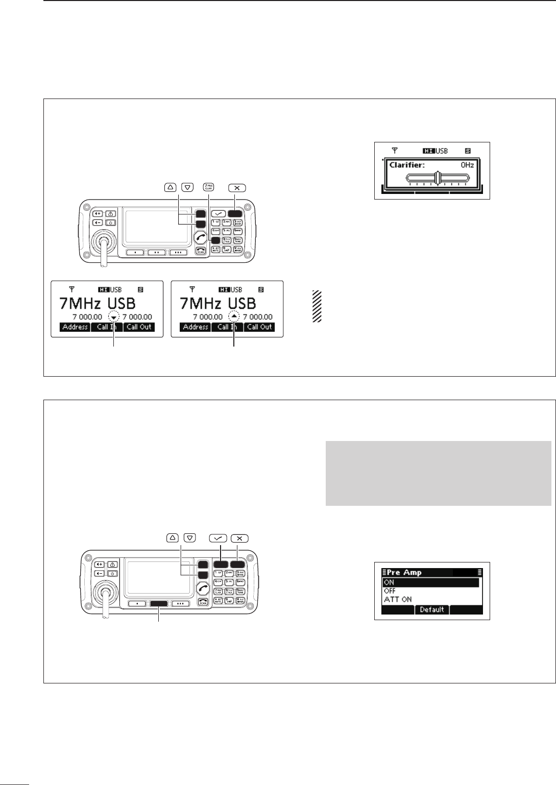
Clarifier function D
The Clarifier function compensates for off-frequency
stations. The function shifts the receive frequency up
to ±200 Hz in 10 Hz steps, without shifting the trans-
mit frequency.
/
Upper shiftLower shift
Push q[CLAR](7) to open the Clarifier adjustment
window.
Push w[r] or [s] to adjust the frequency shift.
• The transmit frequency is not shifted.
Push e[CLAR](7) to save the setting, and return to
the previous screen.
• If desired, push [8] to cancel the setting and exit the
window .
When cancelling the Clarifier function, set the fre-
quency shift to 0 Hz in the Clarifier adjustment win-
dow.
Preamp and Attenuator D
The preamp amplifies received signals in the front
end circuit to improve the S/N ratio and sensitivity.
Turn ON this function to better receive weak signals.
The attenuator prevents strong undesired signals near
the desired frequency or near your location, such as
from a broadcast station, from causing distortion or
spurious signals.
[Default]
/
Push q[8] to enter the Main Menu screen.
Select the “Pre Amp” item of “Setmode.” w
q Push [r] or [s] to select the item, and then
push [4] to open the screen.
(Setmode > Config)
w Push [r] or [s] to select “Pre Amp,” and then
hold down [4] for 1 second.
Push e[r] or [s] to select the desired option, ON,
OFF or ATT ON.
• If desired, hold down [Default](§§) for 1 second to re-
turn to the default setting
.
Push r[4] to save the setting, and return to the pre-
vious screen.
Push t[8] one or more times to exit.
3
15
RECEIVE AND TRANSMIT
3
2001 NEW
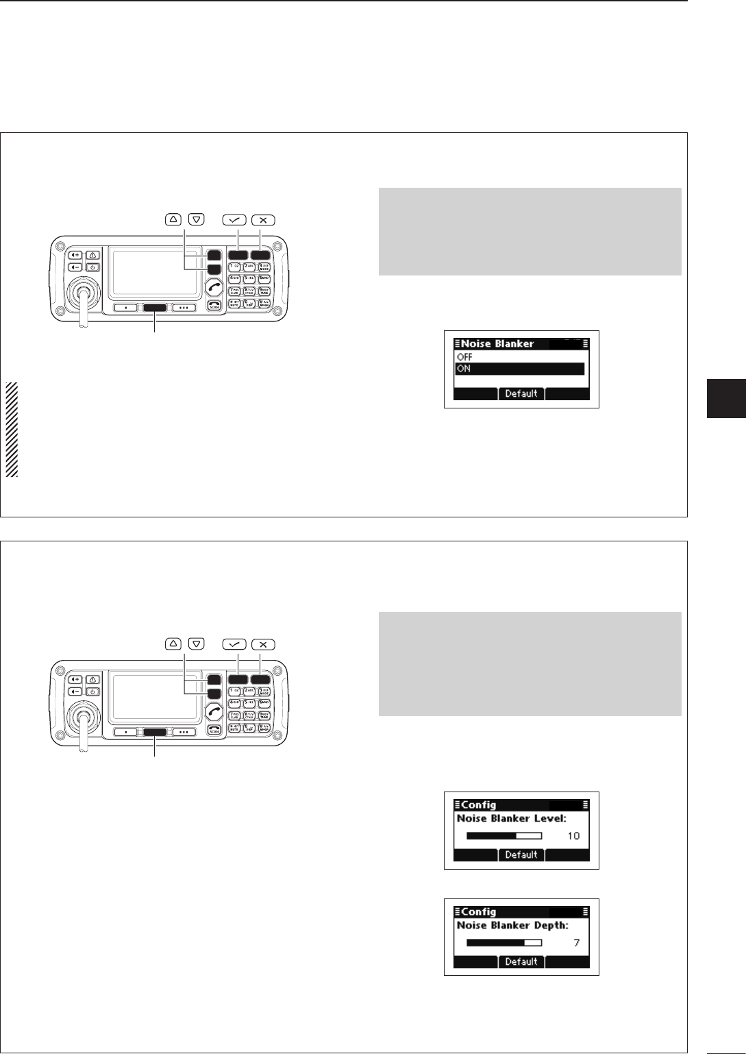
Noise Blanker D
The noise blanker reduces pulse-type noise such as
that generated by automobile ignition systems.
[Default]
/
When using the Noise Blanker function, received
signals may be distorted if they are excessively
strong, or when used on noise other than pulses. In
this case, set the Noise Blanker threshold level to
a shallow position, or turn OFF the function. (See
next topic.)
Push q[8] to enter the Main Menu screen.
Select the “Noise Blanker” item of “Setmode.” w
q Push [r] or [s] to select the item, and then
push [4] to open the screen.
(Setmode > Config)
w Push [r] or [s] to select “Noise Blanker,” and
then hold down [4] for 1 second.
Push e[r] or [s] to turn ON the function.
• If desired, hold down [Default](§§) for 1 second to re-
turn to the default setting
.
Push r[4] to save the setting, and return to the pre-
vious screen.
• If desired, adjust the Noise Blanker Level or Noise
Blanker Depth. See the next topic for details
.
Push t[8] one or more times to exit.
Noise Blanker adjustment D
To deal with various types of noise, the threshold level
and attenuation level can be set by the “Noise Blanker
Level” and “Noise Blanker Depth” items.
[Default]
/
Push q[8] to enter the Main Menu screen.
Select the “Noise Blanker Level” or “Noise Blanker w
Depth” item of “Setmode.”
q Push [r] or [s] to select the item, and then
push [4] to open the screen.
(Setmode > Config)
w Push [r] or [s] to select “Noise Blanker
Level” or “Noise Blanker Depth,” and then hold
down [4] for 1 second.
Push e[r] or [s] to adjust to the desired level.
• If desired, hold down [Default](§§) for 1 second to re-
turn to the default setting
.
Noise Blanker Level: Between 0 and 15.
Noise Blanker Depth: Between 0 and 9.
Push r[4] to save the setting, and return to the pre-
vious screen.
Push t[8] one or more times to exit.
16
3RECEIVE AND TRANSMIT
2001 NEW 2001 NEW
■ Functions for receive (Continued)
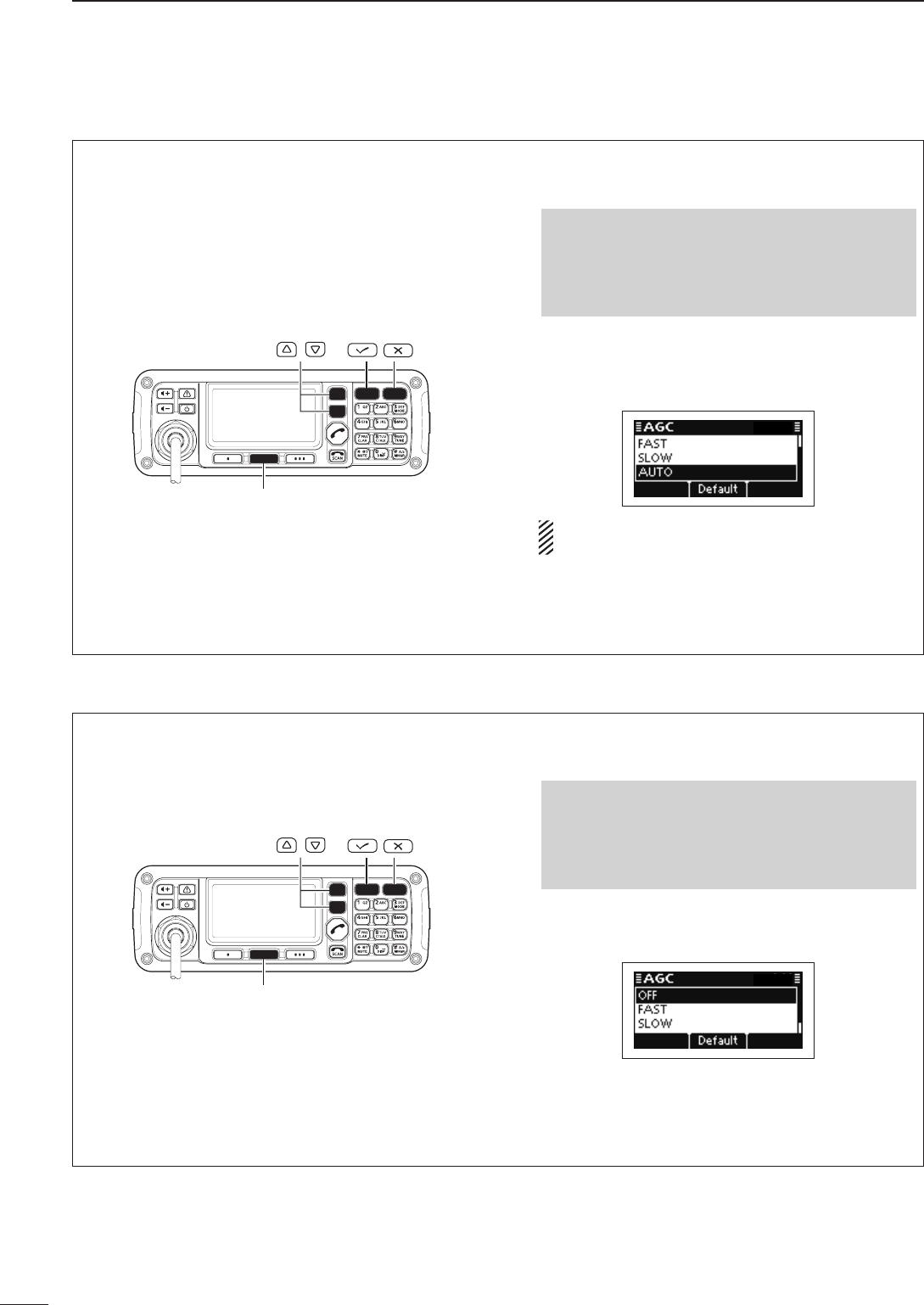
AGC function D
The AGC (automatic gain control) controls receiver
gain to produce a constant audio output level, even
when the received signal strength varies by fading,
and so on.
The transceiver has two AGC characteristics; AUTO
and time constants FAST and SLOW.
[Default]
/
Push q[8] to enter the Main Menu screen.
Select the “AGC” item of “Setmode.” w
q Push [r] or [s] to select the item, and then
push [4] to open the screen.
(Setmode > Config)
w Push [r] or [s] to select “AGC,” and then hold
down [4] for 1 second.
Push e[r] or [s] to select the desired option, FAST,
SLOW or AUTO.
• If desired, hold down [Default](§§) for 1 second to re-
turn to the default setting
.
When AUTO is selected, the AGC time constant
varies, depending on the operating mode.
Push r[4] to save the setting, and return to the pre-
vious screen.
Push t[8] one or more times to exit.
AGC OFF function D
When receiving weak signals with adjacent strong
signals or noise, the AGC function may reduce the
sensitivity. In this situation, the AGC function should
be turned OFF.
[Default]
/
Push q[8] to enter the Main Menu screen.
Select the “AGC” item of “Setmode.” w
q Push [r] or [s] to select the item, and then
push [4] to open the screen.
(Setmode > Config)
w Push [r] or [s] to select “AGC,” and then hold
down [4] for 1 second.
Push e[r] or [s] to turn OFF the function.
• If desired, hold down [Default](§§) for 1 second to re-
turn to the default setting
.
Push r[4] to save the setting, and return to the pre-
vious screen.
Push t[8] one or more times to exit.
2001 NEW
17
3
RECEIVE AND TRANSMIT
1
2
3
4
5
6
7
8
9
10
11
12
13
14
15
16
17
Quick Reference
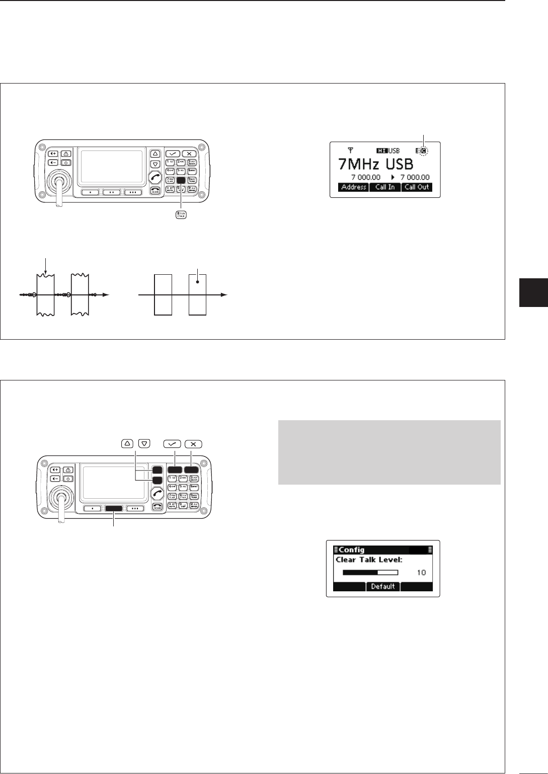
Clear Talk function D
The Clear Talk function uses the DSP circuit to en-
hance desired signals in the presence of noise.
Clear Talk function OFF Clear Talk function ON
Desired
signal (CW)
Noise components
P ➥ush [C TALK](8) to turn ON the Clear Talk function.
• “C” appears when the Clear Talk function is ON.
Appears
• If desired, adjust the Clear Talk level. See the next topic
for details
.
• If desired, push [C TALK](8) again to turn OFF the
function.
Clear Talk Level D
The Clear Talk Level must be adjusted for maximum
readability. Setting the “Clear Talk Level” too high re-
sults in audio signal masking or distortion.
[Default]
/
Push q[8] to enter the Main Menu screen.
Select the “Clear Talk Level” item of “Setmode.” w
q Push [r] or [s] to select the item, and then
push [4] to open the screen.
(Setmode > Config)
w Push [r] or [s] to select “Clear Talk Level”
and then hold down [4] for 1 second.
Push e[r] or [s] to adjust the desired level to be-
tween 1 and 15.
• If desired, hold down [Default](§§) for 1 second to re-
turn to the default setting
.
Push r[4] to save the setting, and return to the pre-
vious screen.
Push t[8] one or more times to exit.

4
18
SELCALL/ALE OPERATION
2001 NEW
Selcall or ALE ■
Selcall uses a 4 or 6-digit ID address and allows you to
make individual or group calls. The ALE (automatic link
establishment) is a system which automatically selects
an available frequency and establishes a communica-
tion link. The IC-F8101 ALE system compiles with ba-
sic requirements of FED-STD-1045A.
Available calls D
•Selectivecall
Selective call allows you to make individual or group
calls using an individual ID (identification) assigned to
each transceiver.
•Phonecall
Allows you to make a Phone call through a telephone
interconnect service provider.
•Messagecall
Allows you to exchange text messages of up to 64
characters* with the intended ID station.
* Icom Selcall: 64 characters (upper case/Lower case
letters)
Open Selcall: 32 characters (Only upper case let-
ter)
•SendPositioncall
Allows you to send your own position information to
the intended ID station.
•GetPositioncall
The Get Position call allows you to request the intend-
ed ID station to send its position information.
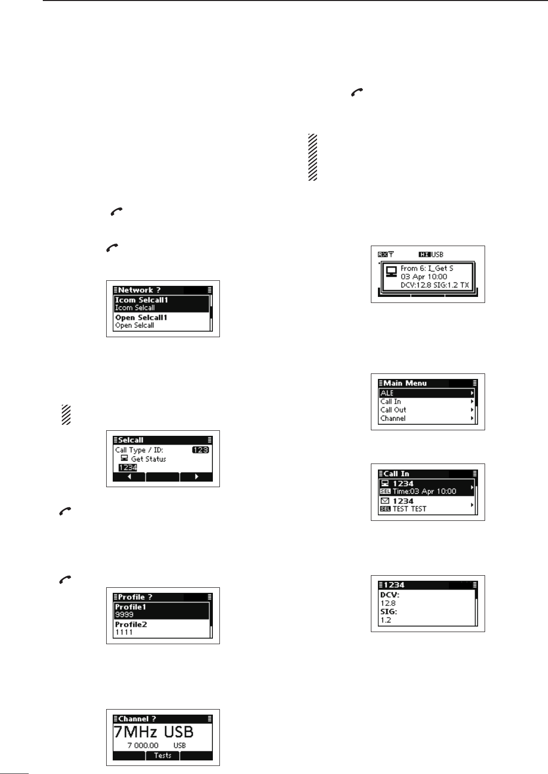
•GetStatuscall(OnlyIcomSelcall)
Requests to send radio status information including
power supply voltage, signal strength, output power,
VSWR, and so on.
•Stuncall(OnlyOpenSelcall)
The Stun call disables the specified station from either
transmitting and receiving.
•RFDSemergencycall(OnlyAustralianversions)
The RFDS (Royal Flying Doctor Service) emergency
call uses a 2-Tone signal for an emergency call.
•Emergencycall
Allows you to send an emergency signal with your own
position information.
• The Icom Selcall uses Icom original commands,
and may not be compatible with other brands.
• Depending on the preprogramming, you can select
the Open Selcall*.
* The Open Selcall is compatible with other trans-
ceiver brands. Ask your dealer for details.
•ChannelTestcall
The Channel Test call allows the user to determine the
signal quality between their transceiver and a specific
transceiver, before making individual or group calls.
•ALEindividualornetcall
Automatically establishes a communication link by us-
ing the ALE table.
•ALEsounding
Automatically sends a sounding signal at a selectable
interval (0.5–11 hours) to check the propagation, and
stores the data in a table. Manual soundings can also
be sent.
•ALEAMD(AutomaticMessageDisplay)
Automatically sends and receives text messages of up
to 90 characters.
19
4
SELCALL/ALE OPERATION
4
The Selcall function allows you to make individual or
group calls. Each transceiver is assigned an individual
ID (identification) and can be called using this ID.
•PreparationforaSelectivecall
Send a Channel Test call on several Selcall channels,
and check the propagation on each one to select the
channel with the best signal quality. (p. 26)
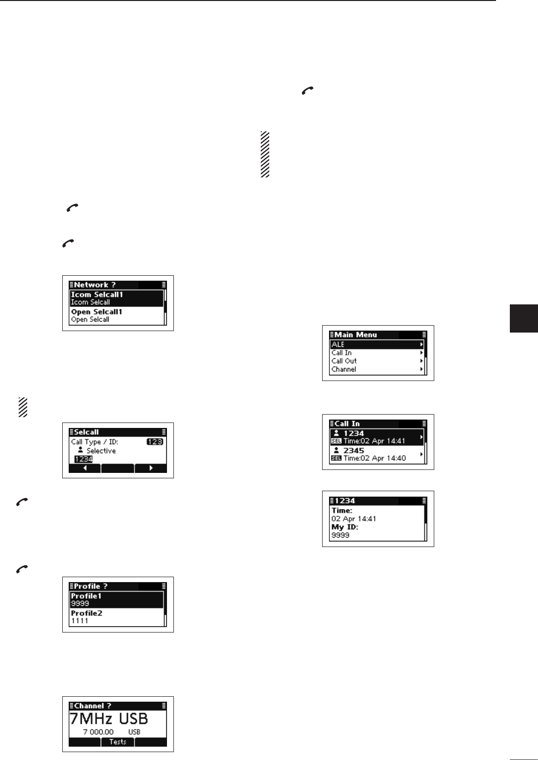
•SendingaSelectivecall
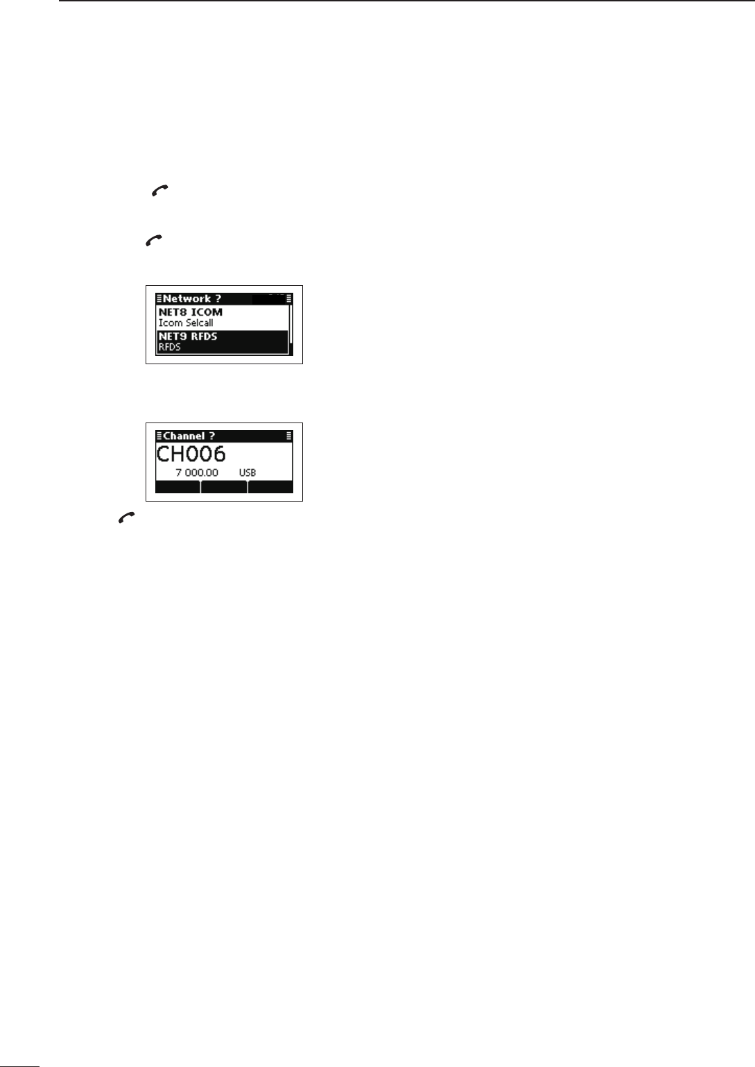
Hold down q[ ] for 1 second to enter the Network
selection screen.
Push w[r] or [s] to select the desired Network, and
then push [ ].
• The Networks that belong to the Icom Selcall or Open
Selcall systems must be selected.
Push e[r] or [s] to select the Call Type to “Selec-
tive.”
• “Selective,” “Phone,” “Message,” “Send Position,” “Get Posi-
tion,” “Get Status,” “Emergency,” “Channel Test” and “Stun”
are selectable.
The Get Status call is selectable in the Icom Selcall,
and the Stun call is selectable in the Open Selcall.
Push keypad to enter the Call ID, and then push r
[ ].
• The previously entered Call ID is displayed.
• Push [t](§) or [u](§§§) to move the cursor.
• Push [8] to delete the digit to the left of the cursor.
• This Call ID is not stored in the Call ID list.
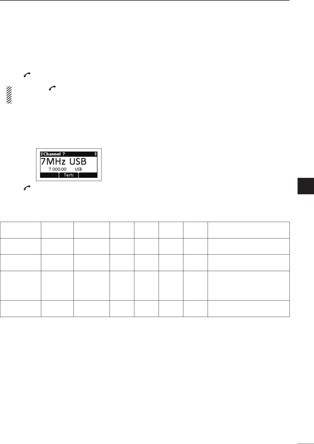
Push t[r] or [s] to select the Profile, then push
[ ].
Push y[r] or [s] to select the Channel.
• Only the channels that belong to the selected Network in
step w, are displayed.
• If desired, push [Tests](§§) to transmit the Channel Test
call in this step.
Push u[ ] to transmit the Selective call. The call is
stored in the Call Out memory.
• While calling, push [PTT] to cancel the call.
You can also make a Selective call when the Ad-
dress screen is displayed. In this case, you can skip
several steps, see page 29 for the Simple Selcall
operation details.
•ReceivingSelectivecalls
When your transceiver receives a Selective call with
your individual ID, it automatically responds by trans-
mitting. The received Selcall is stored in the Call In
memory.
Push q[8] to enter the Main Menu screen.
Push w[r] or [s] to select “Call In,” and then push
[4].
Push e[r] or [s] to select the desired Call, and then
push [4].
Push r[r] or [s] to select the information.
Push t[8] twice to return to the normal operating
screen.
Selective call D
20
4SELCALL/ALE OPERATION
2001 NEW 2001 NEW
Allows you to make Phone calls through a telephone
interconnect service provider.
•PreparationforaPhonecall
Send a Channel Test call on several Phone call chan-
nels, and check the propagation on each one to select
the channel with the best signal quality. (p. 26)
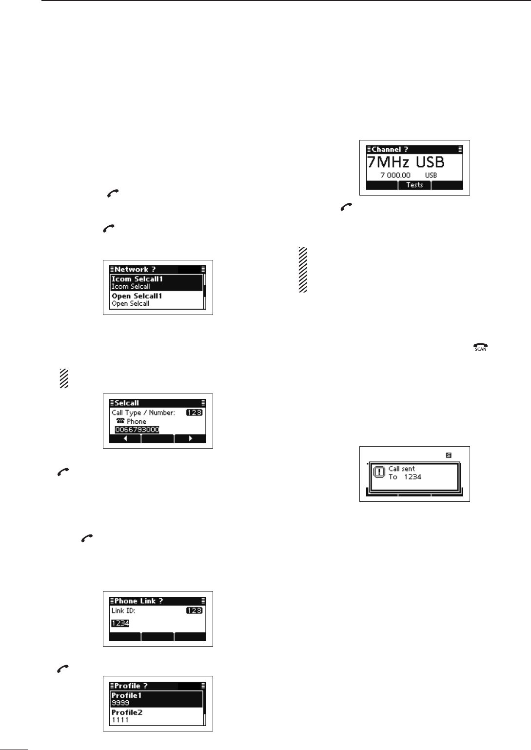
• Sending a Phone call
Hold down q[ ] for 1 second to enter the Network
selection screen.
Push w[r] or [s] to select the desired Network, and
then push [ ].
• The Networks that belong to the Icom Selcall or Open
Selcall systems must be selected.
Push e[r] or [s] to select the Call Type to “Phone.”
• “Selective,” “Phone,” “Message,” “Send Position,” “Get Posi-
tion,” “Get Status,” “Emergency,” “Channel Test” and “Stun”
are selectable.
The Get Status call is selectable in the Icom Selcall,
and the Stun call is selectable in the Open Selcall.
Push keypad to enter the Number, and then push r
[ ].
• The previously entered Number is displayed.
• Push [t](§) or [u](§§§) to move the cursor.
• Push [8] to delete the digit to the left of the cursor.
• This Number is not stored in the Number list.
Push keypad to enter the Phone Link ID, and then t
push [ ].
• The previously entered Link ID is displayed.
• Push [t](§) or [u](§§§) to move the cursor.
• Push [8] to delete the digit to the left of the cursor.
• This ID is not stored in the Phone Link ID list.
Push y[r] or [s] to select the Profile, then push
[ ].
Push u[r] or [s] to select the Channel.
• Only the channels that belong to the selected Network in
step w, are displayed.
• If desired, push [Tests](§§) to transmit the Channel Test
call in this step.
Push i[ ] to transmit the Phone call. The call is
stored in the Call Out memory.
• While calling, push [PTT] to cancel the call.
You can also make a Phone call when the Address
screen is displayed. In this case, you can skip sev-
eral steps, see page 29 for the Simple Selcall opera-
tion details.
•AfteraPhonecall
q When a Phone call is finished, push [ ] to trans-
mit the disconnect call.
• Until the Disconnect call is transmitted, the telephone
interconnect service provider continues counting the
time for toll charging.
• If the “Auto Start Type” item of “Setmode” is set to “Scan”
or “Termination,” the Call automatically disconnects after
the Auto Start Wait Time period has past with no opera-
tion. (Setmode > Call)
Phone call D
2001 NEW
21
4
SELCALL/ALE OPERATION
1
2
3
4
5
6
7
8
9
10
11
12
13
14
15
16
17
Quick Reference
The Message call allows you to exchange text mes-
sages of up to 64 characters,* with the intended ID
station, and also leave a message at the station.
* Icom Selcall: 64 characters
(upper case/Lower case letters)
Open Selcall: 32 characters (Only upper case letter)
• Preparation for a Message call
Send a Channel Test call on several Selcall channels,
and check the propagation on each one to select the
channel with the best signal quality. (p. 26)
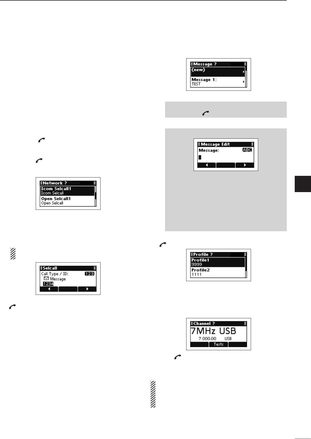
•SendingaMessagecall
Hold down q[] for 1 second to enter the Network
selection screen.
Push w[r] or [s] to select the desired Network, and
then push [ ].
• The Networks that belong to the Icom Selcall or Open
Selcall systems must be selected.
Push e[r] or [s] to select the Call Type to “Mes-
sage.”
• “Selective,” “Phone,” “Message,” “Send Position,” “Get Posi-
tion,” “Get Status,” “Emergency,” “Channel Test” and “Stun”
are selectable.
The Get Status call is selectable in the Icom Selcall,
and the Stun call is selectable in the Open Selcall.
Push keypad to enter the Call ID, and then push r
[ ].
• The previously entered Call ID is displayed.
• Push [t](§) or [u](§§§) to move the cursor.
• Push [8] to delete the digit to the left of the cursor.
• This Call ID is not stored in the Call ID list.
Select the desired Message or edit New message. t
❍ Message selection
Push ➥[r] or [s] select the Message, and
then push [ ].
❍ New Message input
q Hold down [4] to enter the input mode.
w Push keypad to enter the Message.
• Push [A/a](#) to toggle between the Upper,
Lower case letter input modes and Number in-
put mode.
• Push [8] to delete the character, symbol or num-
ber to the left of the cursor.
• Push [t](§) or [u](§§§) to move the cursor.
e Push [4] to save the Message.
• This Message is not stored in the Message list.
Push y[r] or [s] to select the Profile, then push
[ ].
Push u[r] or [s] to select the Channel.
• Only the channels that belong to the selected Network in
step w, are displayed.
• If desired, push [Tests](§§) to transmit the Channel Test
call in this step.
Push i[ ] to transmit the Message call. The call is
stored in the Call Out memory.
• While calling, push [PTT] to cancel the call.
You can also make a Message call when the Ad-
dress screen is displayed. In this case, you can skip
several steps, see page 29 for the Simple Selcall
operation details.
Message call D
22
4SELCALL/ALE OPERATION
2001 NEW 2001 NEW
The Send Position call allows you to send your own
position and time information to the intended ID sta-
tion.
•PreparationforaSendPositioncall
Send a Channel Test call on several Selcall channels,
and check the propagation on each one to select the
channel with the best signal quality. (p. 26)
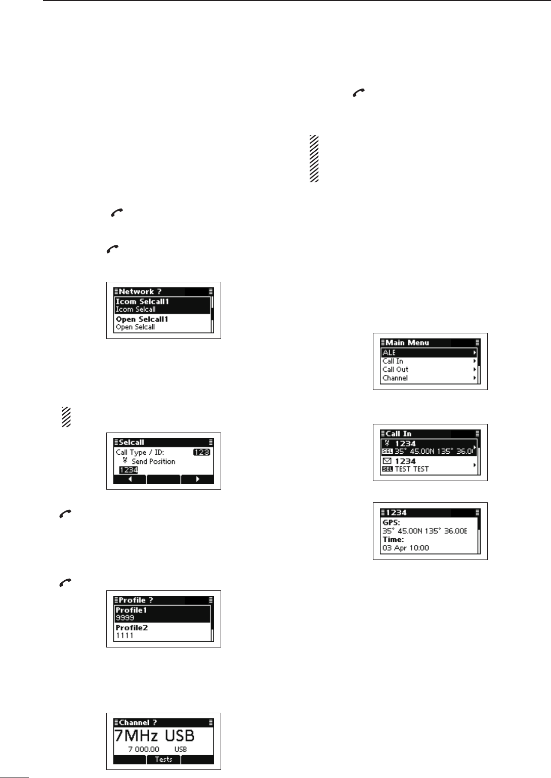
•SendingaSendPositioncall
Hold down q[ ] for 1 second to enter the Network
selection screen.
Push w[r] or [s] to select the desired Network, and
then push [ ].
• The Networks that belong to the Icom Selcall or Open
Selcall systems must be selected.
Push e[r] or [s] to select the Call Type to “Send
Position.”
• “Selective,” “Phone,” “Message,” “Send Position,” “Get Posi-
tion,” “Get Status,” “Emergency,” “Channel Test” and “Stun”
are selectable.
The Get Status call is selectable in the Icom Selcall,
and the Stun call is selectable in the Open Selcall.
Push keypad to enter the Call ID, and then push r
[ ].
• The previously entered Call ID is displayed.
• Push [t](§) or [u](§§§) to move the cursor.
• Push [8] to delete the digit to the left of the cursor.
• This Call ID is not stored in the Call ID list.
Push t[r] or [s] to select the Profile, then push
[ ].
Push y[r] or [s] to select the Channel.
• Only the channels that belong to the selected Network in
step w, are displayed.
• If desired, push [Tests](§§) to transmit the Channel Test
call in this step.
Push u[ ] to transmit the Send Position call. The
call is stored in the Call Out memory.
• While calling, push [PTT] to cancel the call.
You can also make a Send Position call when the
Address screen is displayed. In this case, you can
skip several steps, see page 29 for the Simple Sel-
call operation details.
•ReceivingSendPositioncalls
When your transceiver receives a Send Position call
with your individual ID, it automatically responds by
transmitting. The received Selcall is stored in the Call
In memory.
Push q[8] to enter the Main Menu screen.
Push w[r] or [s] to select “Call In,” and then push
[4].
Push e[r] or [s] to select the desired Call, and then
push [4].
Push r[r] or [s] to select the information.
Push t[8] twice to return to the normal operating
screen.
Send Position call D
2001 NEW
23
4
SELCALL/ALE OPERATION
1
2
3
4
5
6
7
8
9
10
11
12
13
14
15
16
17
Quick Reference
The Get Position call allows you to request an intended
ID station to send its position information.
•PreparationforaGetPositioncall
Send a Channel Test call on several Selcall channels,
and check the propagation on each one to select the
channel with the best signal quality. (p. 26)
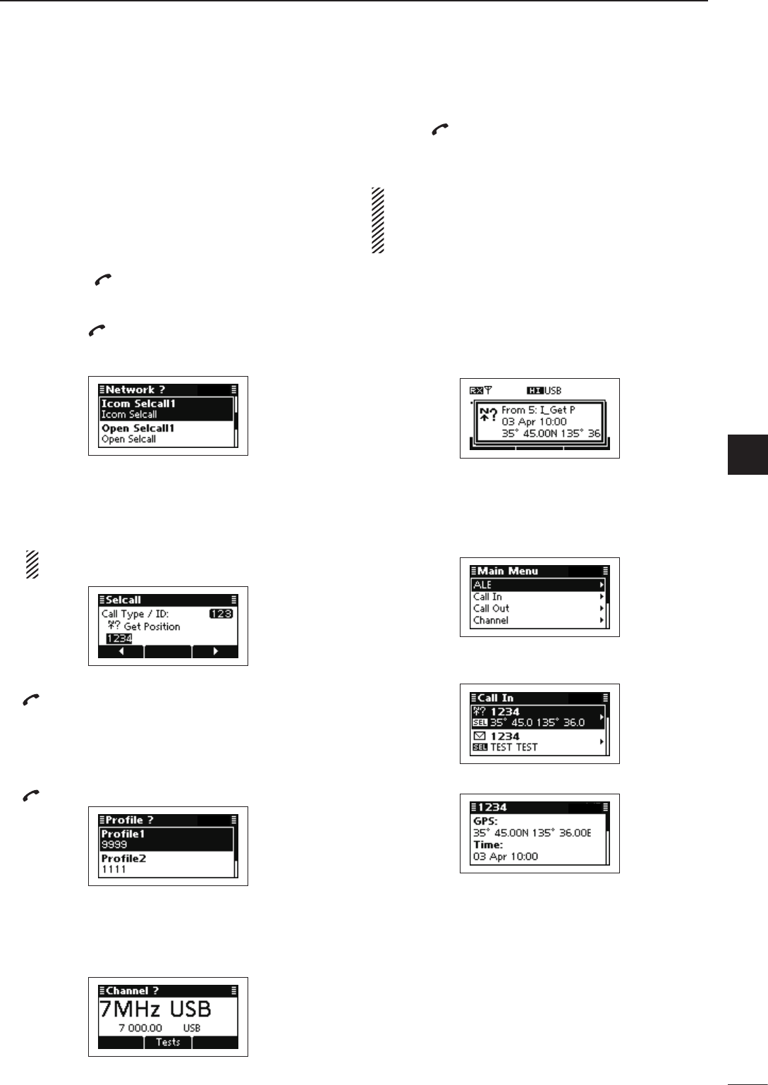
•SendingaGetPositioncall
Hold down q[ ] for 1 second to enter the Network
selection screen.
Push w[r] or [s] to select the desired Network, and
then push [ ].
• The Networks that belong to the Icom Selcall or Open
Selcall systems must be selected.
Push e[r] or [s] to select the Call Type to “Get Posi-
tion.”
• “Selective,” “Phone,” “Message,” “Send Position,” “Get Posi-
tion,” “Get Status,” “Emergency,” “Channel Test” and “Stun”
are selectable.
The Get Status call is selectable in the Icom Selcall,
and the Stun call is selectable in the Open Selcall.
Push keypad to enter the Call ID, and then push r
[ ].
• The previously entered Call ID is displayed.
• Push [t](§) or [u](§§§) to move the cursor.
• Push [8] to delete the digit to the left of the cursor.
• This Call ID is not stored in the Call ID list.
Push t[r] or [s] to select the Profile, then push
[ ].
Push y[r] or [s] to select the Channel.
• Only the channels that belong to the selected Network in
step w, are displayed.
• If desired, push [Tests](§§) to transmit the Channel Test
call in this step.
Push u[ ] to transmit the Send Position call. The
call is stored in the Call Out memory.
• While calling, push [PTT] to cancel the call.
You can also make a Get Position call when the Ad-
dress screen is displayed. In this case, you can skip
several steps, see page 29 for the Simple Selcall
operation details.
•ReceivingaGetPositioncallacknowledgement
After the call is transmitted, your called station q
sends position and time information as an acknowl-
edgement.
Push any key to return to the normal operating w
screen.
Push e[8] to enter the Main Menu screen.
Push r[r] or [s] to select “Call In,” and then push
[4].
Push t[r] or [s] to select the desired Call, and then
push [4].
Push y[r] or [s] to select the information.
Push u[8] twice to return to the normal operating
screen.
•ReceivingaGetPositioncall
When your transceiver receives a Get Position call that
includes your individual ID, it automatically responds
by transmitting.
Get Position call D
24
4SELCALL/ALE OPERATION
2001 NEW 2001 NEW
The Get Status call requests sending radio status
information including power supply voltage, signal
strength, output power, VSWR, and so on.
•PreparationforaGetStatuscall
Send a Channel Test call on several Selcall channels,
and check the propagation on each one to select the
channel with the best signal quality. (p. 26)
•SendingaGetStatuscall
Hold down q[ ] for 1 second to enter the Network
selection screen.
Push w[r] or [s] to select the desired Network, and
then push [ ].
• The Networks that belong to the Icom Selcall or Open
Selcall systems must be selected.
Push e[r] or [s] to select the Call Type to “Get Sta-
tus.”
• “Selective,” “Phone,” “Message,” “Send Position,” “Get Posi-
tion,” “Get Status,” “Emergency,” “Channel Test” and “Stun”
are selectable.
The Get Status call is selectable in the Icom Selcall,
and the Stun call is selectable in the Open Selcall.
Push keypad to enter the Call ID, and then push r
[ ].
• The previously entered Call ID is displayed.
• Push [t](§) or [u](§§§) to move the cursor.
• Push [8] to delete the digit to the left of the cursor.
• This Call ID is not stored in the Call ID list.
Push t[r] or [s] to select the Profile, then push
[ ].
Push y[r] or [s] to select the Channel.
• Only the channels that belong to the selected Network in
step w, are displayed.
• If desired, push [Tests](§§) to transmit the Channel Test
call in this step.
Push u[ ] to transmit the Send Position call. The
call is stored in the Call Out memory.
• While calling, push [PTT] to cancel the call.
You can also make a Get Status call when the Ad-
dress screen is displayed. In this case, you can skip
several steps, see page 29 for the Simple Selcall
operation details.
•ReceivingaGetStatuscallacknowledgement
After the call is transmitted, your called station sends q
status information as an acknowledgement.
Push any key to return to the normal operating w
screen.
Push e[8] to enter the Main Menu screen.
Push r[r] or [s] to select “Call In,” and then push
[4].
Push t[r] or [s] to select the desired Call, and then
push [4].
Push y[r] or [s] to select the information.
• Status information includes the power supply voltage,
Signal strength, Transmit power, VSWR, Time, Self ID,
Network and Channel/Mode.
Push u[8] twice to return to the normal operating
screen.
•ReceivingaGetStatuscall
When your transceiver receives a Get Status call that
includes your individual ID, it automatically responds
by transmitting.
Get Status call (Only Icom Selcall) D
25
4
SELCALL/ALE OPERATION
4
2001 NEW
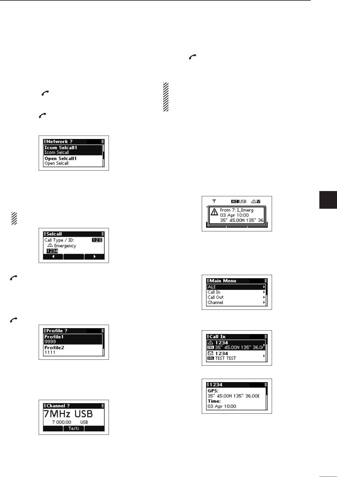
The Emergency call allows you to broadcast an emer-
gency signal with your own position information.
•SendinganEmergencycall
Hold down q[ ] for 1 second to enter the Network
selection screen.
Push w[r] or [s] to select the desired Network, and
then push [ ].
• The Networks that belong to the Icom Selcall or Open
Selcall systems must be selected.
Push e[r] or [s] to select the Call Type to “Emer-
gency.”
• “Selective,” “Phone,” “Message,” “Send Position,” “Get Posi-
tion,” “Get Status,” “Emergency,” “Channel Test” and “Stun”
are selectable.
The Get Status call is selectable in the Icom Selcall,
and the Stun call is selectable in the Open Selcall.
Push keypad to enter the Call ID, and then push r
[ ].
• The previously entered Call ID is displayed.
• Push [t](§) or [u](§§§) to move the cursor.
• Push [8] to delete the digit to the left of the cursor.
• This Call ID is not stored in the Call ID list.
Push t[r] or [s] to select the Profile, then push
[ ].
Push y[r] or [s] to select the Channel.
• Only the channels that belong to the selected Network in
step w, are displayed.
• If desired, push [Tests](§§) to transmit the Channel Test
call in this step.
Push u[ ] to transmit the Emergency call. The call
is stored in the Call Out memory.
• While calling, push [PTT] to cancel the call.
You can also make an Emergency call when the Ad-
dress screen is displayed. In this case, you can skip
several steps, see page 29 for the Simple Selcall
operation details.
•ReceivingEmergencycalls
When your transceiver receives an Emergency call
with your individual ID, it automatically responds by
transmitting. The received Selcall is stored in the Call
In memory.
After an Emergency call is received, transceiver dis- q
plays the station’s position and its time.
Push any key to return to the normal operating w
screen.
Push e[8] to enter the Main Menu screen.
Push r[r] or [s] to select “Call In,” and then push
[4].
Push t[r] or [s] to select the desired Call, and then
push [4].
Push y[r] or [s] to select the information.
Push u[8] twice to return to the normal operating
screen.
Emergency call D
26
4SELCALL/ALE OPERATION
2001 NEW 2001 NEW
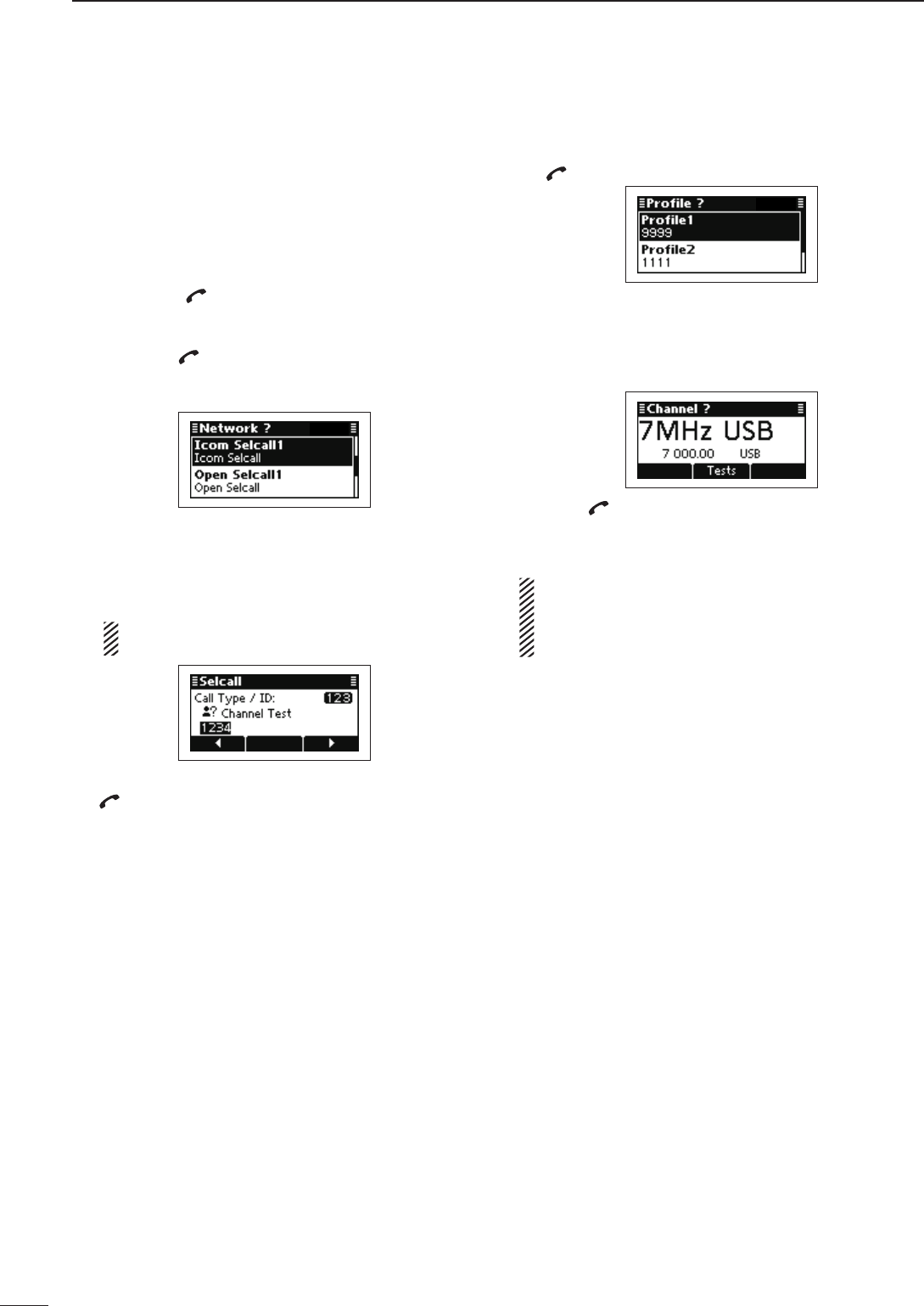
The Channel Test call allows the user determine the
signal quality between your transceiver and a specif-
ic transceiver before an individual or group call. The
Channel Test call is also used for checking the channel
before sending any other calls.
•SendingaChannelTestcall
Hold down q[ ] for 1 second to enter the Network
selection screen.
Push w[r] or [s] to select the desired Network, and
then push [ ].
• The Networks that belong to the Icom Selcall or Open
Selcall systems must be selected.
Push e[r] or [s] to select the Call Type to “Channel
Test.”
• “Selective,” “Phone,” “Message,” “Send Position,” “Get Posi-
tion,” “Get Status,” “Emergency,” “Channel Test” and “Stun”
are selectable.
The Get Status call is selectable in the Icom Selcall,
and the Stun call is selectable in the Open Selcall.
Push keypad to enter the Call ID, and then push r
[ ].
• The previously entered Call ID is displayed.
• Push [t](§) or [u](§§§) to move the cursor.
• Push [8] to delete the digit to the left of the cursor.
• This Call ID is not stored in the Call ID list.
Push t[r] or [s] to select the Profile, then push
[ ].
Push y[r] or [s] to select the Channel.
• Only the channels that belong to the selected Network in
step w, are displayed.
• If desired, push [Tests](§§) to transmit the Channel Test
call in this step.
Push u[ ] to transmit the Channel Test call. The call
is stored in the Call Out memory.
• While calling, push [PTT] to cancel the call.
You can also make a Channel Test call when the Ad-
dress screen is displayed. In this case, you can skip
several steps, see page 29 for the Simple Selcall
operation details.
Channel Test call D
2001 NEW
27
4
SELCALL/ALE OPERATION
1
2
3
4
5
6
7
8
9
10
11
12
13
14
15
16
17
Quick Reference
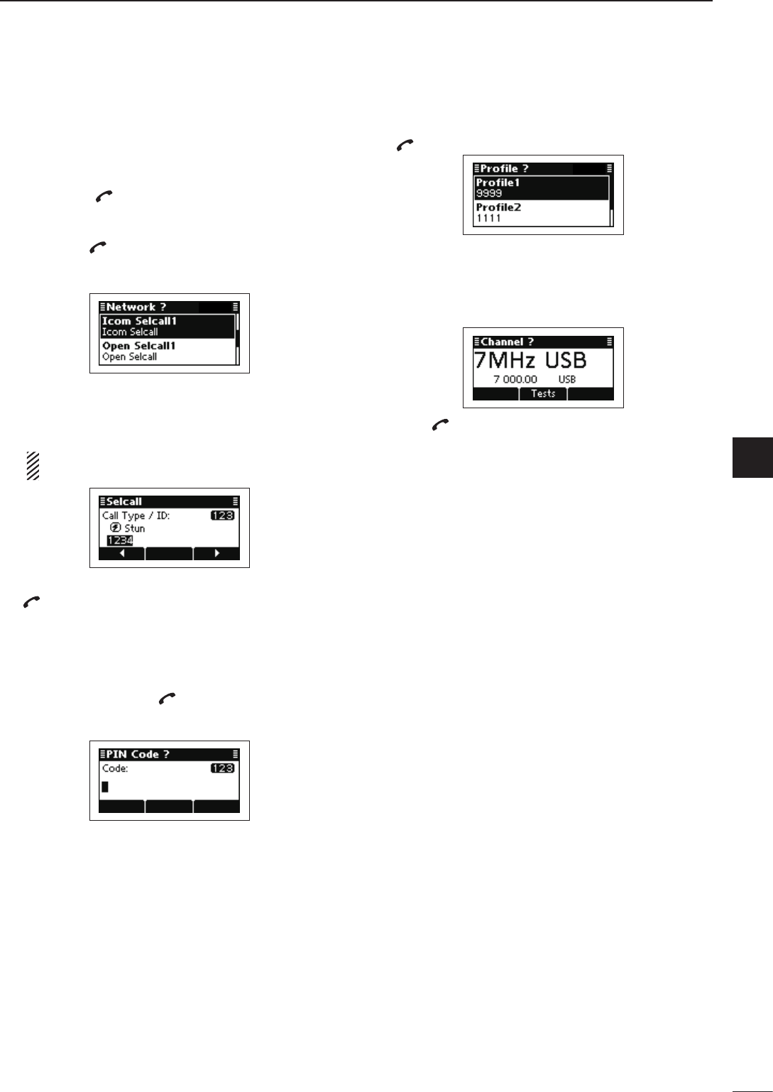
The Stun call disables the specified station from either
transmitting and receiving.
•SendingaStuncall
Hold down q[ ] for 1 second to enter the Network
selection screen.
Push w[r] or [s] to select the desired Network, and
then push [ ].
• The Networks that belong to the Open Selcall system
must be selected.
Push e[r] or [s] to select the Call Type to “Stun.”
• “Selective,” “Phone,” “Message,” “Send Position,” “Get Posi-
tion,” “Get Status,” “Emergency,” “Channel Test” and “Stun”
are selectable.
The Get Status call is selectable in the Icom Selcall,
and the Stun call is selectable in the Open Selcall.
Push keypad to enter the Call ID, and then push r
[ ].
• The previously entered Call ID is displayed.
• Push [t](§) or [u](§§§) to move the cursor.
• Push [8] to delete the digit to the left of the cursor.
• This Call ID is not stored in the Call ID list.
Push keypad to enter the specified station’s PIN t
Code, and then push [ ].
• Push [t](§) or [u](§§§) to move the cursor.
• Push [8] to delete the digit to the left of the cursor.
Push y[r] or [s] to select the Profile, then push
[ ].
Push u[r] or [s] to select the Channel.
• Only the channels that belong to the selected Network in
step w, are displayed.
• If desired, push [Tests](§§) to transmit the Channel Test
call in this step.
Push i[ ] to transmit the Stun call. The call is stored
in the Call Out memory.
• While calling, push [PTT] to cancel the call.
Stun call (Only Open Selcall) D
28
4SELCALL/ALE OPERATION
2001 NEW 2001 NEW
The RFDS (Royal Flying Doctor Service) emergency
call uses a 2-Tone signal for an emergency call.
•SendinganRFDSemergencycall
Hold down q[] for 1 second to enter the Network
selection screen.
Push w[r] or [s] to select the desired Network, and
then push [ ].
• The Networks that belong to the RFDS systems must be
selected.
Push e[r] or [s] to select the Channel.
• Only the channels that belong to the selected Network in
step w, are displayed.
Push r[ ] to transmit the RFDS emergency call.
The call is stored in the Call Out memory.
• While calling, push [PTT] to cancel the call.
RFDS emergency call (only AUS versions) D
29
4
SELCALL/ALE OPERATION
4
2001 NEW
Simple Selcall operation D
The Simple Selcall mode is convenient to transmit the
often used Selcalls.
Push q[ ] to enter the Simple Selcall mode.
• Depending on the Entry, the contents are skipped.
Holding down
[ ] enters
the normal Selcall mode.
See pages 19 to 28 for the normal Selcall operation de-
tails.
After setting is finished, push w[r] or [s] to select
the Channel.
• Only the channels that belong to the selected Network,
are displayed.
• If desired, push [Tests](§§) to transmit the Channel Test
call in this step.
Push e[ ] to transmit the Call.
• While calling, push [PTT] to cancel the call.
Depending on the Entry, following settings are required.
(4 : Setting is required. — : The contents is skipped.)
Screen
(Entry) Call system/
Network Call type/
Call ID Phone
Link*4Message
*5Self ID
*3Channel
*6Note
Address
Emergency Link —*1—*3———4The skipped contents are used
from the preprogrammed setting.
Call In
Call Out —*1—*3———4The skipped contents are used
from the preprogrammed setting.
Phone Link —*14 4 — — 4
The Call type is always set to
Phone.
The skipped contents are used
from the preprogrammed setting.
Other screen — *24 4 4 —4The skipped contents are used from
the previously transmitted Calls.
*1 When the setting of the Entry is effective (Call is
possible), the content is skipped.
*2 Priority Network is used.
*3 When the preprogrammed ID or previously used ID
exists in the selected entry, the Call automatically
selects the ID and skips the contents.
*4 Only Phone call.
*5 Only Message call.
*6 Only the channels that belong to the Network, are
displayed.
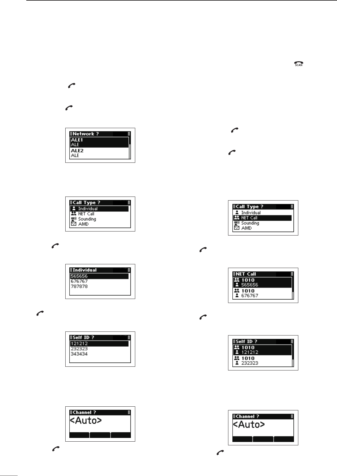
30
4SELCALL/ALE OPERATION
2001 NEW 2001 NEW
Automatically establish a communication link by using
the ALE table.
•SendinganIndividualcall
Hold down q[ ] for 1 second to enter the Network
selection screen.
Push w[r] or [s] to select the desired Network, and
then push [ ].
• The Networks that belong to the ALE system must be
selected.
Push e[r] or [s] to select the Call Type to “Individ-
ual.”
• “Individual,” “NET Call,” “Sounding” and “AMD” are select-
able.
Push r[r] or [s] to select the Individual ID, and then
push [ ].
• Only the ID that belong to the selected Network in step
w, are displayed.
Push t[r] or [s] to select the Self ID, then push
[ ].
• Only the ID that belong to the selected Network in step
w, are displayed.
Push y[r] or [s] to select the Channel.
• Only the channels that belong to the selected Network in
step w, are displayed.
• If <Auto> is selected, the transceiver sequentially trans-
mits channels that belong to the Network.
Push u[ ] to transmit the Individual call. The call is
stored in the Call Out memory.
• While calling, push [PTT] to cancel the call.
• After an ALE call
After an ALE call is finished, push ➥[ ] to transmit
the disconnect call.
• If the “Auto Start Type” item of “Setmode” is set to “Scan”
or “Termination,” the Call automatically disconnects after
the Auto Start Wait Time period has past with no opera-
tion. (Setmode > Call)
•SendingaNetcall
Hold down q[ ] for 1 second to enter the Network
selection screen.
Push w[r] or [s] to select the desired Network, and
then push [ ].
• The Networks that belong to the ALE system must be
selected.
Push e[r] or [s] to select the Call Type to “NET
Call.”
• “Individual,” “NET Call,” “Sounding” and “AMD” are select-
able.
Push r[r] or [s] to select the NET ID, and then push
[ ].
• Only the ID that belong to the selected Network in step
w, are displayed.
Push t[r] or [s] to select the Self ID, then push
[ ].
• Only the ID that belong to the selected Network in step
w, are displayed.
Push y[r] or [s] to select the Channel.
• Only the channels that belong to the selected Network in
step w, are displayed.
• If <Auto> is selected, the transceiver sequentially trans-
mits channels that belong to the Network.
Push u[ ] to transmit the NET Call. The call is
stored in the Call Out memory.
• While calling, push [PTT] to cancel the call.
ALE call D
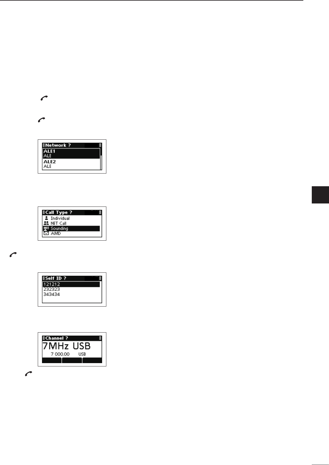
31
4
SELCALL/ALE OPERATION
4
2001 NEW
Automatically sends a sounding signal at certain in-
tervals (0.5–11 hours) to check the propagation, and
then stores the data in a table. Manual soundings can
also be made.
•Manualsounding
Hold down q[ ] for 1 second to enter the Network
selection screen.
Push w[r] or [s] to select the desired Network, and
then push [ ].
• The Networks that belong to the ALE system must be
selected.
Push e[r] or [s] to select the Call Type to “Sound-
ing.”
• “Individual,” “NET Call,” “Sounding” and “AMD” are select-
able.
Push r[r] or [s] to select the Self ID, then push
[ ].
• Only the ID that belong to the selected Network in step
w, are displayed.
Push t[r] or [s] to select the Channel.
• Only the channels that belong to the selected Network in
step w, are displayed.
Push y[ ] to transmit the Sounding call.
• While calling, push [PTT] to cancel the call.
ALE Sounding D
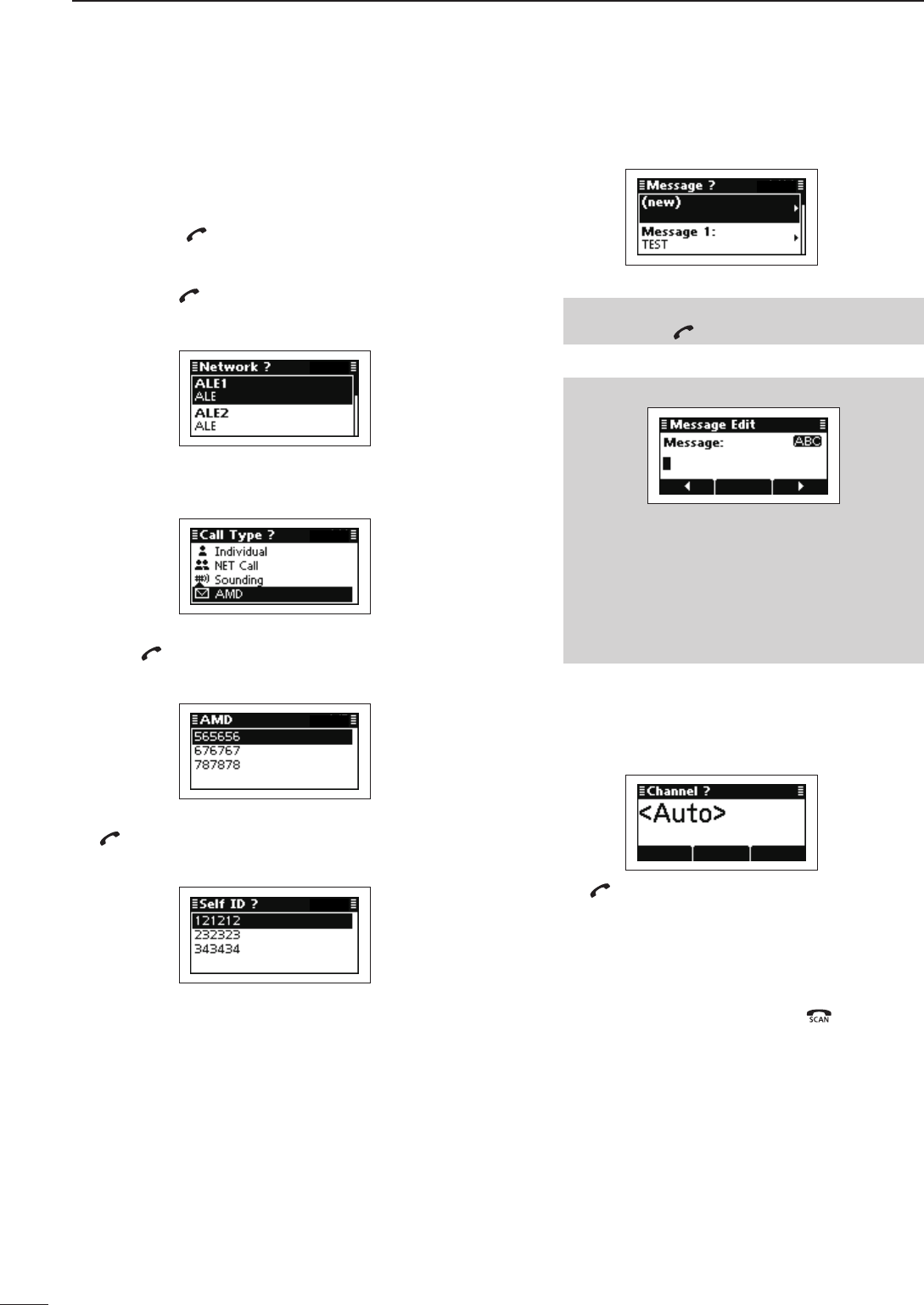
2001 NEW
32
4SELCALL/ALE OPERATION
2001 NEW
The ALE AMD (Automatic Message Display) sends
and receives test messages of up to 90 characters.
•SendinganAMDcall
Hold down q[ ] for 1 second to enter the Network
selection screen.
Push w[r] or [s] to select the desired Network, and
then push [ ].
• The Networks that belong to the ALE system must be
selected.
Push e[r] or [s] to select the Call Type to “AMD.”
• “Individual,” “NET Call,” “Sounding” and “AMD” are select-
able.
Push r[r] or [s] to select the Individual ID, and then
push [ ].
• Only the ID that belong to the selected Network in step
w, are displayed.
Push t[r] or [s] to select the Self ID, then push
[ ].
• Only the ID that belong to the selected Network in step
w, are displayed.
Select the desired Message or edit New message. t
❍ Message selection
Push ➥[r] or [s] select the Message, and
then push [ ].
❍ New Message input
q Hold down [4] to enter the input mode.
w Push keypad to enter the Message.
• Push [A/a](#) to toggle between the Upper case
letter and Number input mode.
• Push [8] to delete the character, symbol or num-
ber to the left of the cursor.
• Push [t](§) or [u](§§§) to move the cursor.
e Push [4] to save the Message.
• This Message is not stored in the Message list.
Push y[r] or [s] to select the Channel.
• Only the channels that belong to the selected Network in
step w, are displayed.
• If <Auto> is selected, the transceiver sequentially trans-
mits channels that belong to the Network.
Push u[ ] to transmit the Individual call. The call is
stored in the Call Out memory.
• While calling, push [PTT] to cancel the call.
• After an ALE call
After an ALE call is finished, push ➥[ ] to transmit
the disconnect call.
• If the “Auto Start Type” item of “Setmode” is set to “Scan”
or “Termination,” the Call automatically disconnects after
the Auto Start Wait Time period has past with no opera-
tion. (Setmode > Call)
ALE AMD call D

2001 NEW
5
33
MENU SCREEN
2001 NEW
1
2
3
4
5
6
7
8
9
10
11
12
13
14
15
16
17
Quick Reference
■ Manager Menu
The Manager Menu is used for logging into the Admin-
istrator mode, setting the Access rights, programming
memory channel, Selcall address and so on.
Admin Login/Admin Logout
Selects the Login mode, the Administrator
and User modes are exclusively selectable.
Access Rights
Restricts the displaying or editing items in the
User mode.
This item only appears when the Login mode
is the Administrator mode.
Hidden
Set to the Admin Hidden setting ON or
OFF.
Lock
Select the Admin Lock ON or OFF.
Built-in Test
Self-checks the transceiver’s condition. Auto
Sequentially tests the ‘Logic,’ ‘Receiver’
and ‘Transmitter’ items.
Logic
Tests the ‘Logic’ item.
Receiver
Tests the ‘Receiver’ item.
Transmitter
Tests the ‘Transmitter’ item.
Create Entry
Makes new entry of the ALE, Channel, Net-
work or Selcall.
ALE
Makes new ALE items, Call ID, Net ID or
Self ID.
Call ID
NET ID
Self ID
Channel
Makes new memory channel.
Network
Makes and registers new Network.
Selcall
Makes new Selcall items. Address
Phone Link
Profile
Delete Entry
Deletes the entry that is selected before en-
tering the Manager Menu.
Display
Displays the Access Rights settings.
Information
Displays the variety information. Date/Time
GPS
Priority Network
Unit
Version
Setup
This is a Setup wizard to make a new Entry. Channel
Network
ALE Self ID
Selcall Profile
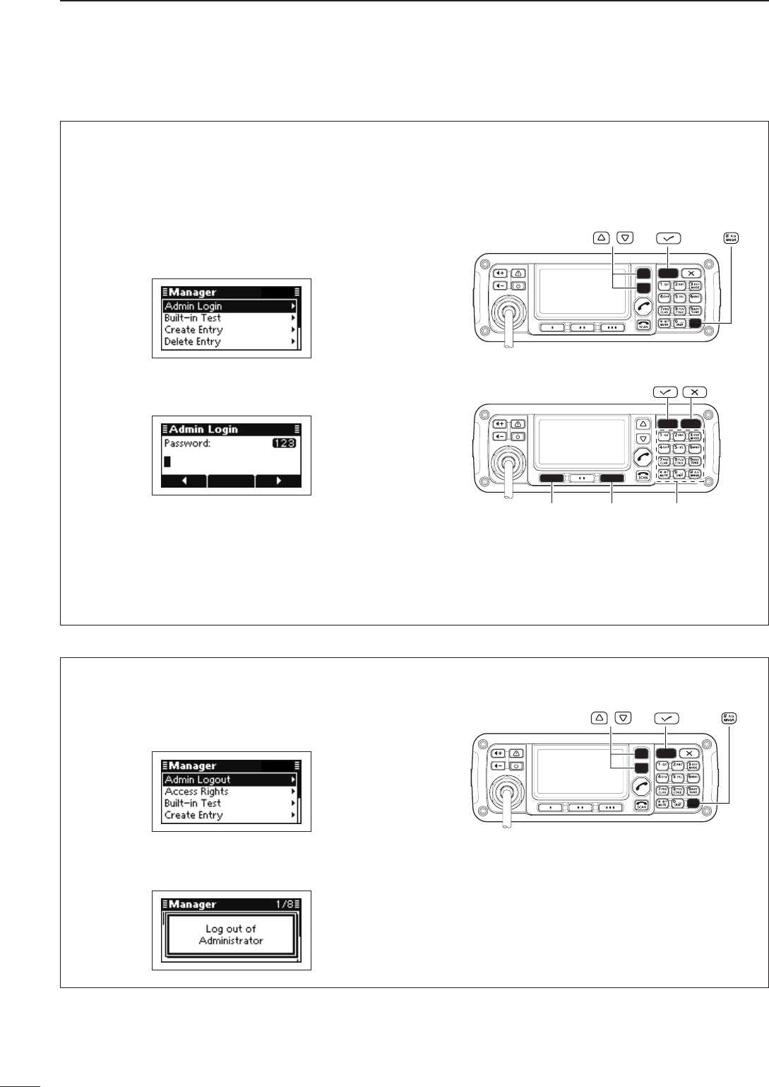
34
5MENU SCREEN
2001 NEW
Manager Menu (Continued) ■
Entering the Administrator mode D
When first entering the Administrator mode, a login
password may be required, depending on the prepro-
gramming.
Push q[MNGR](#) to enter the Manager Menu
screen.
• “Admin Login” is automatically selected. If “Admin Log-
in” is not selected, push [r] to select it.
Push w[4] to enter the Administrator mode.
• Depending on the preprogramming, the “Admin Login”
may appear, and then the password is requested.
Push the keypad keys to enter the Administrator e
password, and then push [4].
• Repeatedly push [A/a](#) to select the character group,
ABC (upper case letters), abc (lower case letters) or
123 (numbers).
• Push [8] to delete a character.
• Push [t](§) or [u](§§§) to move the cursor.
/
[][]Keypad
D Return to the User mode
Push q[MNGR](#) to enter the Manager Menu
screen.
• “Admin Logout” is automatically selected. If “Admin
Logout” is not selected, push [r] to select it.
Push w[4] to enter the User mode.
• “Log out of Administrator” is displayed, and then the
transceiver returns to the User mode.
/
2001 NEW
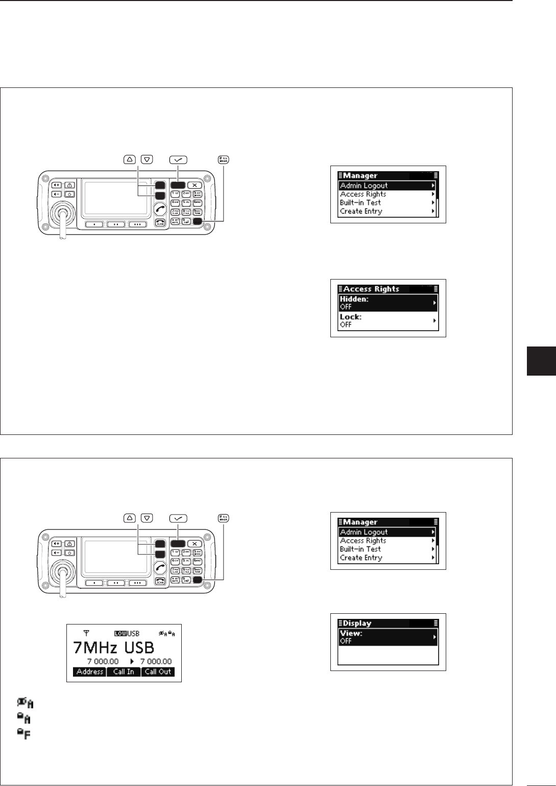
2001 NEW
35
5
MENU SCREEN
1
2
3
4
5
6
7
8
9
10
11
12
13
14
15
16
17
Quick Reference
Setting the Access Rights D
You can restrict the editing or displaying of a memory
channel, Selcall address or any other settings in the
User mode.
/
Select a memory channel, Selcall address or other q
setting.
Push w[MNGR](#) to enter the Manager Menu
screen.
• “Admin Logout” is automatically selected.
Push e[r] or [s] to select “Access Rights,” and
then push [4].
Push r[r] or [s] to select the item, and then hold
down [4] for 1 second.
Push t[r] or [s] to select “ON,” and then push
[4].
Hidden: Undisplayed in the Use mode.
Lock: Locked and editing is restricted in the
User mode.
• The setting is effective after the transceiver returns to
the User mode.
Setting the Access Rights View D
You can confirm the restriction of the memory chan-
nel, Selcall address or any other settings.
/
(Display example)
: Appears when the “Hidden” setting is ON.
: Appears when the “Lock” setting is ON.
: Appears when the Factory Lock setting is
ON.
This setting cannot be changed in either the
Administrator or User mode.
Push q[MNGR](#) to enter the Manager Menu
screen.
• “Admin Logout” is automatically selected.
Push w[r] or [s] to select “Display,” and then push
[4].
Hold down e[4] for 1 second.
Push r[r] or [s] to select “ON,” and then push
[4].
Select the desired memory channel, Selcall ad- t
dress or setting that you want to check in the “Ac-
cess Rights” setting.
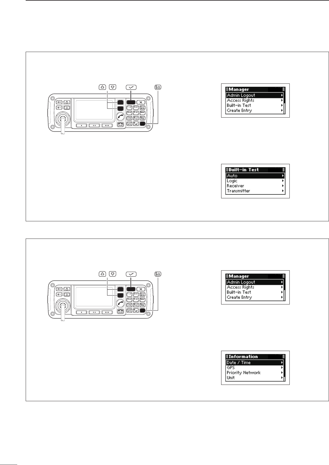
36
5MENU SCREEN
2001 NEW
Manager Menu (Continued) ■
Built-in Test D
You can check the transceiver’s condition by using
the “Built-in Test” item.
/
Push q[MNGR](#) to enter the Manager Menu
screen.
• “Admin Logout” is automatically selected.
Push w[r] or [s] to select “Built-in Test,” and then
push [4].
Push e[r] or [s] to select the item, and then push
[4] to start testing.
• “Auto,” “Logic,” “Receiver” and “Transmitter” are select-
able.
• If any problems are found, “Test failed” appears.
• If no problems are found, “Test passed” appears.
Information D
You can display a variety of information by using the
“Information” item.
/
Push q[MNGR](#) to enter the Manager Menu
screen.
• “Admin Logout” is automatically selected.
Push w[r] or [s] to select “Information,” and then
push [4].
Push e[r] or [s] to select the item, and then push
[4] to display the information.
• “Date/Time,” “GPS,” “Priority Network,” “Unit” and “Ver-
sion” are selectable.
• “GPS” requires data from an external GPS unit.
2001 NEW
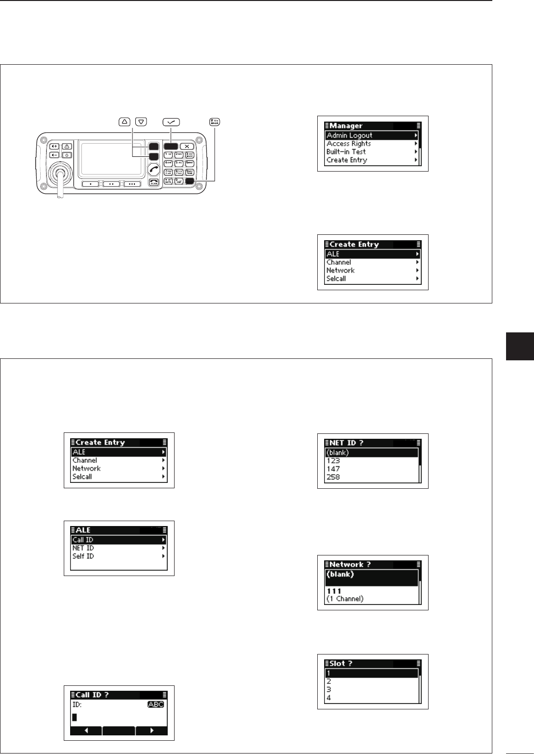
2001 NEW
37
5
MENU SCREEN
1
2
3
4
5
6
7
8
9
10
11
12
13
14
15
16
17
Quick Reference
Create Entry D
You can create new entries that are ALE, Channel,
Network or Selcall items.
/
Push q[MNGR](#) to enter the Manager Menu
screen.
• “Admin Logout” is automatically selected.
Push w[r] or [s] to select “Create Entry,” and then
push [4].
Create the desired entry as follows. e
• “ALE,” “Channel,” “Network” or “Selcall” can be select-
ed.
•ALE
A Call ID, NET ID or Self ID can be created.
Making a Call ID or Self ID
Push q[r] or [s] to select “ALE,” and then push
[4].
Push w[r] or [s] to select a Call ID or Self ID, and
then push [4] to enter the input mode.
Push Keypad to enter the desired ID, and then e
push [4].
• Up to 15 characters can be entered.
• Usable characters are A to Z, 0 to 9, ? and @.
• Push [A/a](#) to toggle between the Alphabet (Upper
case letter) input mode and Number input mode.
• Push [8] to delete the character, symbol or number to
the left of the cursor.
• Push [t](§) or [u](§§§) to move the cursor.
If the entered ID belongs to the specified NET ID, r
push [r] or [s] to select the ID, and then push
[4].
• If the entered ID does not belong to any network, select
(blank) and push [4].
If the entered ID uses with the specified Network t
group, push [r] or [s] to select the Network, and
then push [4].
• If the entered ID does not use with any network group,
select (blank) and push [4].
If any NET ID is selected in step y r, select Slot
number.
• Selectable number are 1 to 20.
Push u[4] to save the ID and exit.
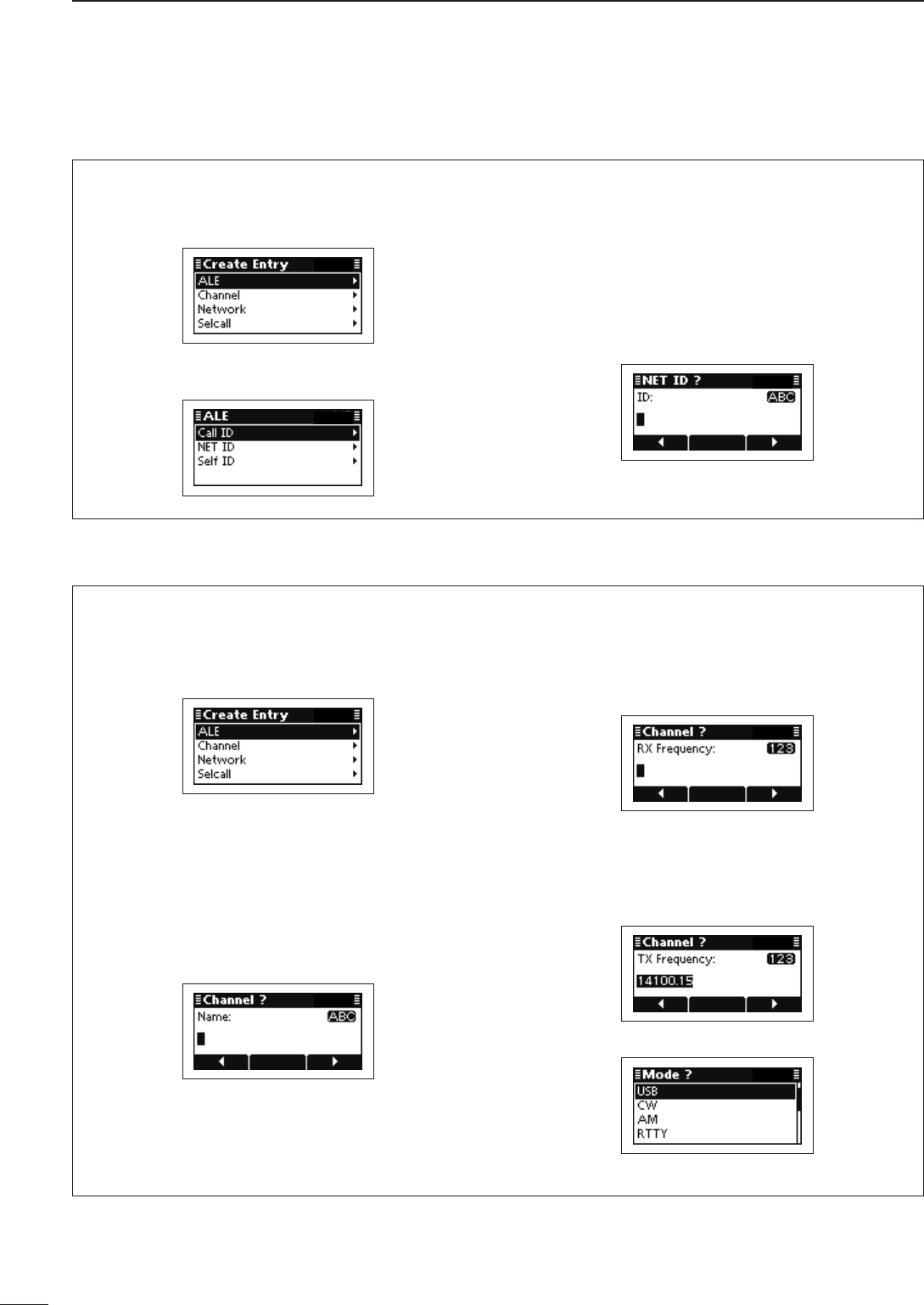
38
5MENU SCREEN
2001 NEW
•ALE
Making a NET ID
Push q[r] or [s] to select “ALE,” and then push
[4].
Push w[r] or [s] to select a NET ID, and then push
[4] to enter the input mode.
Push Keypad to enter the desired ID, and then e
push [4].
• Up to 15 characters can be entered.
• Usable characters are A to Z, 0 to 9, ? and @.
• Push [A/a](#) to toggle between the Alphabet (Upper
case letter) input mode and Number input mode.
• Push [8] to delete the character, symbol or number to
the left of the cursor.
• Push [t](§) or [u](§§§) to move the cursor.
Push r[4] to save the ID and exit.
•Channel
A new memory channel can be created.
Push q[r] or [s] to select “Channel,” and then push
[4] to enter the input mode.
Push Keypad to enter the Channel name, and then w
push [4].
• Up to 20 characters can be entered.
• See page 2 for the usable characters details.
• Push [A/a](#) to toggle between the Upper, Lower case
letter input modes and Number input mode.
• Push [8] to delete the character, symbol or number to
the left of the cursor.
• Push [t](§) or [u](§§§) to move the cursor.
Push Keypad to enter the receive frequency, and e
then push [4].
• Push [M] to enter the decimal point.
• Push [8] to delete the number.
• Push [t](§) or [u](§§§) to move the cursor.
Push Keypad to enter the transmit frequency, and r
then push [4].
• Push [M] to enter the decimal point.
• Push [8] to delete the number.
• Push [t](§) or [u](§§§) to move the cursor.
Push t[r] or [s] to select the operating mode.
Push y[4] to save the channel and exit.
Manager Menu ■
Create Entry (Continued) D
2001 NEW
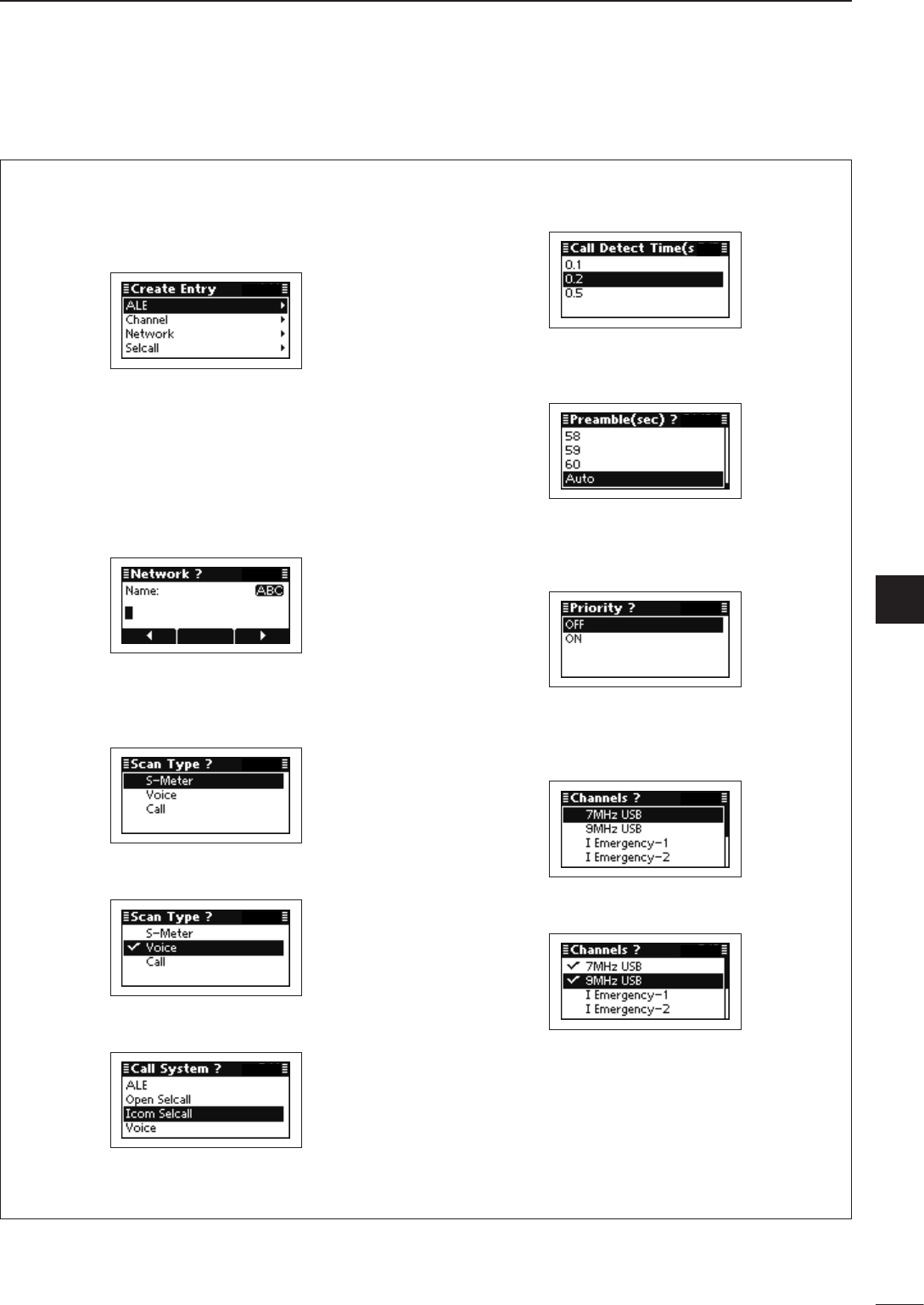
2001 NEW
39
5
MENU SCREEN
1
2
3
4
5
6
7
8
9
10
11
12
13
14
15
16
17
Quick Reference
•Network
A new network can be created.
Push q[r] or [s] to select “Network,” and then push
[4] to enter the input mode.
Push Keypad to enter the Network name, and then w
push [4].
• Up to 20 characters can be entered.
• See page 2 for the usable characters details.
• Push [A/a](#) to toggle between the Upper, Lower case
letter input modes and Number input mode.
• Push [8] to delete the character, symbol or number to
the left of the cursor.
• Push [t](§) or [u](§§§) to move the cursor.
Push e[r] or [s] to select the Scan type, and then
push [4] to select or deselect.
• “4” appears to the left of the selected scan type.
• If desired, up to three scan types can be selected.
Hold down r[4] for 1 second to go to the next
screen.
Push t[r] or [s] to select the Call system, and
then push [4].
Push y[r] or [s] to select the Call detect time, and
then push [4].
Push u[r] or [s] to select the Preamble, and then
push [4].
• Selectable times are 1 to 60 seconds and Auto.
Push i[r] or [s] to select the Priority setting.
• Priority setting can be set to only one Network. If this
setting is set to ON, the previously selected Priority
Network is automatically set to OFF.
Push o[r] or [s] to select the memory channels,
and then push [4] to select or deselect.
• “4” appears to the left of the selected channel.
• If desired, several channels can be selected.
!0 Hold down [4] for 1 second to save the network
and exit.
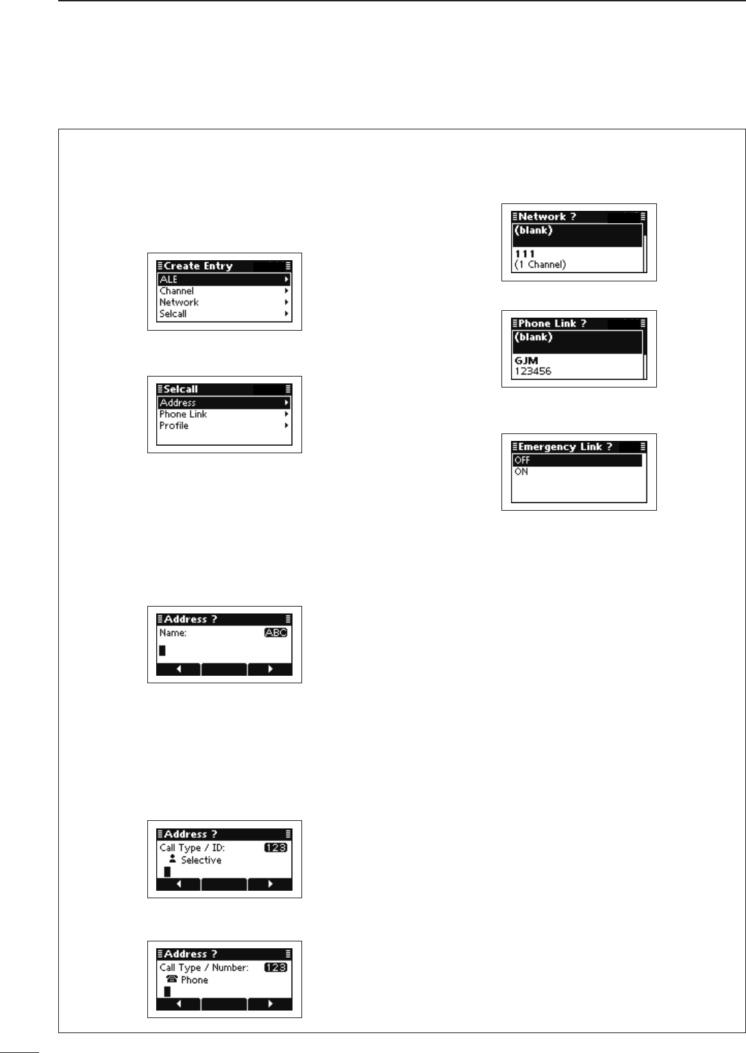
40
5MENU SCREEN
2001 NEW
•Selcall
A new Selcall entry, Address, Phone Link or Profile,
can be created.
Making an Address
Push q[r] or [s] to select “Selcall,” and then push
[4].
Push w[r] or [s] to select “Address,” and then push
[4] to enter the input mode.
Push Keypad to enter the Address name, and then e
push [4].
• Up to 20 characters can be entered.
• See page 2 for the usable characters details.
• Push [A/a](#) to toggle between the Upper, Lower case
letter input modes and Number input mode.
• Push [8] to delete the character, symbol or number to
the left of the cursor.
• Push [t](§) or [u](§§§) to move the cursor.
Push r[r] or [s] to select the Call type.
Then push keypad to enter the ID or number, and
push [4].
• Push [8] to delete the character, symbol or number to
the left of the cursor.
• Push [t](§) or [u](§§§) to move the cursor.
<Call type is other than Phone>
• Up to 6 digits can be entered.
<Call type is Phone>
• Up to 16 digits can be entered.
Push t[r] or [s] to select a network group or
Phone Link.
<Call type is other than Phone>
<Call type is Phone>
Push y[r] or [s] to select the Emergency Link ON
or OFF.
Push u[4] to save the channel and exit.
Manager Menu ■
Create Entry (Continued) D
2001 NEW
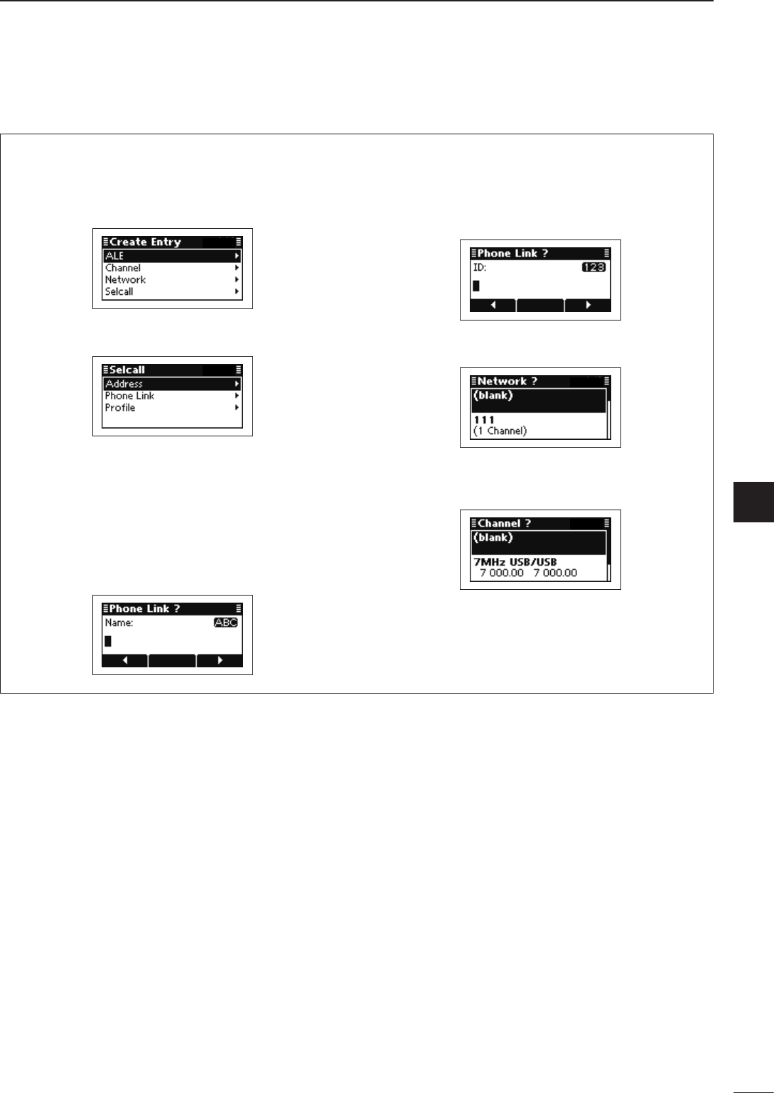
2001 NEW
41
5
MENU SCREEN
1
2
3
4
5
6
7
8
9
10
11
12
13
14
15
16
17
Quick Reference
•Selcall
Making a Phone Link
Push q[r] or [s] to select “Selcall,” and then push
[4].
Push w[r] or [s] to select “Phone Link,” and then
push [4] to enter the input mode.
Push Keypad to enter the Phone Link name, and e
then push [4].
• Up to 20 characters can be entered.
• See page 2 for the usable characters details.
• Push [A/a](#) to toggle between the Upper, Lower case
letter input modes and Number input mode.
• Push [8] to delete the character, symbol or number to
the left of the cursor.
• Push [t](§) or [u](§§§) to move the cursor.
Push keypad to enter the ID, and then push r[4].
• Up to 6 digits can be entered.
• Push [8] to delete the character, symbol or number to
the left of the cursor.
• Push [t](§) or [u](§§§) to move the cursor.
Push t[r] or [s] to select a network group, and
then push [4].
Push y[r] or [s] to select the memory channels.
• Only the memory channels that belong to the selected
network group in step t, are selectable.
Push u[4] to save the Phone Link and exit.
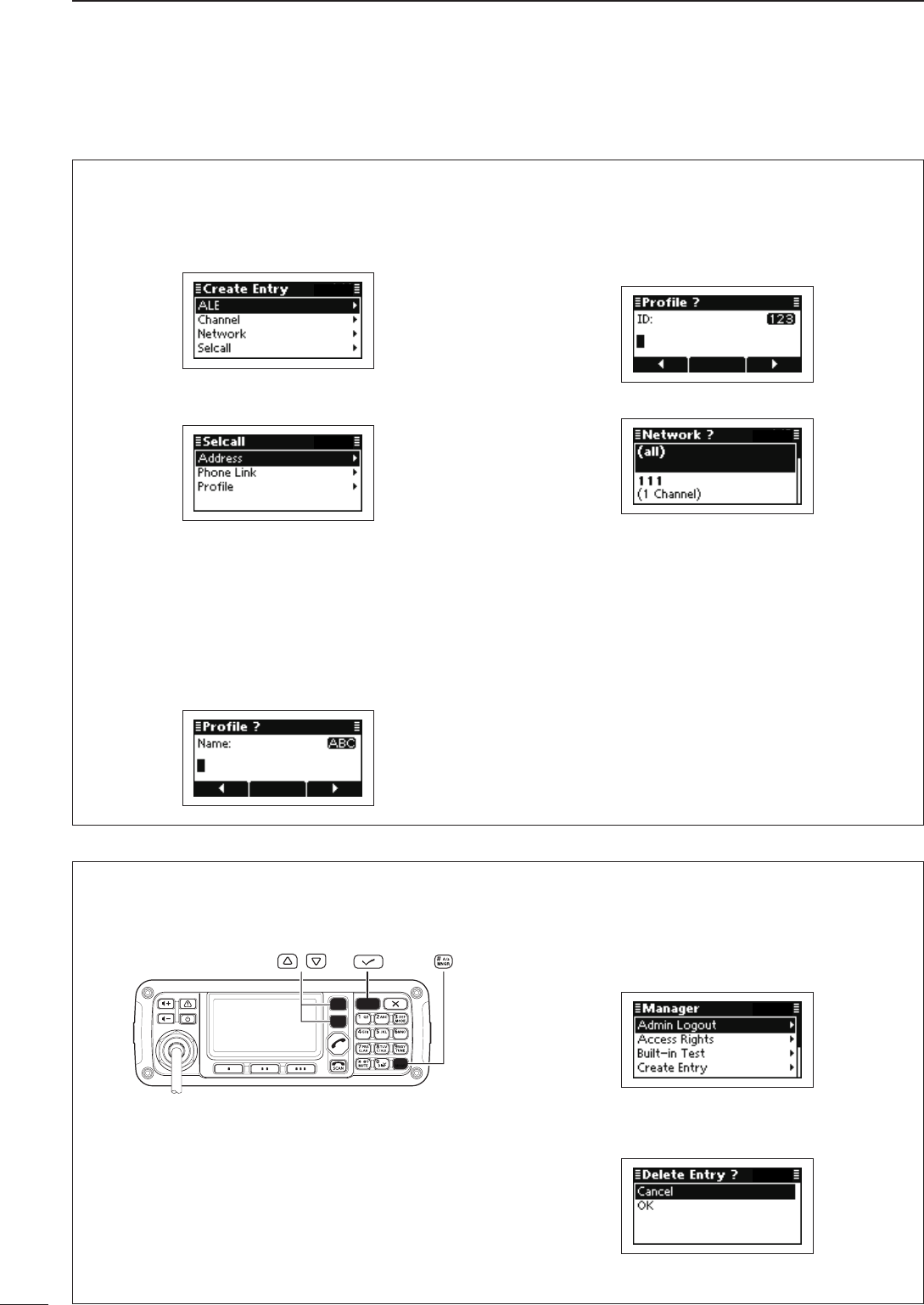
42
5MENU SCREEN
2001 NEW 2001 NEW
Delete Entry D
Any no-longer-used entries, such as memory chan-
nels or Selcall addresses can be cleared.
/
Select a memory channel, Selcall address or some q
other setting that you want to clear.
Push w[MNGR](#) to enter the Manager Menu
screen.
• “Admin Logout” is automatically selected.
Push e[r] or [s] to select “Delete Entry,” and then
push [4].
• The conrmation screen, “Delete Entry?” appears.
Push r[s] to select “OK,” and then push [4].
•Selcall
Making a Profile
Push q[r] or [s] to select “Selcall,” and then push
[4].
Push w[r] or [s] to select “Profile,” and then push
[4] to enter the input mode.
Push Keypad to enter the Profile name, and then e
push [4].
• Up to 20 characters can be entered.
• See page 2 for the usable characters details.
• Push [A/a](#) to toggle between the Upper, Lower case
letter input modes and Number input mode.
• Push [8] to delete the character, symbol or number to
the left of the cursor.
• Push [t](§) or [u](§§§) to move the cursor.
Push keypad to enter the ID, and then push r[4].
• Up to 6 digits can be entered.
• Push [8] to delete the character, symbol or number to
the left of the cursor.
• Push [t](§) or [u](§§§) to move the cursor.
Push t[r] or [s] to select a network group.
Push y[4] to save the Profile and exit.
Manager Menu ■
Create Entry (Continued) D
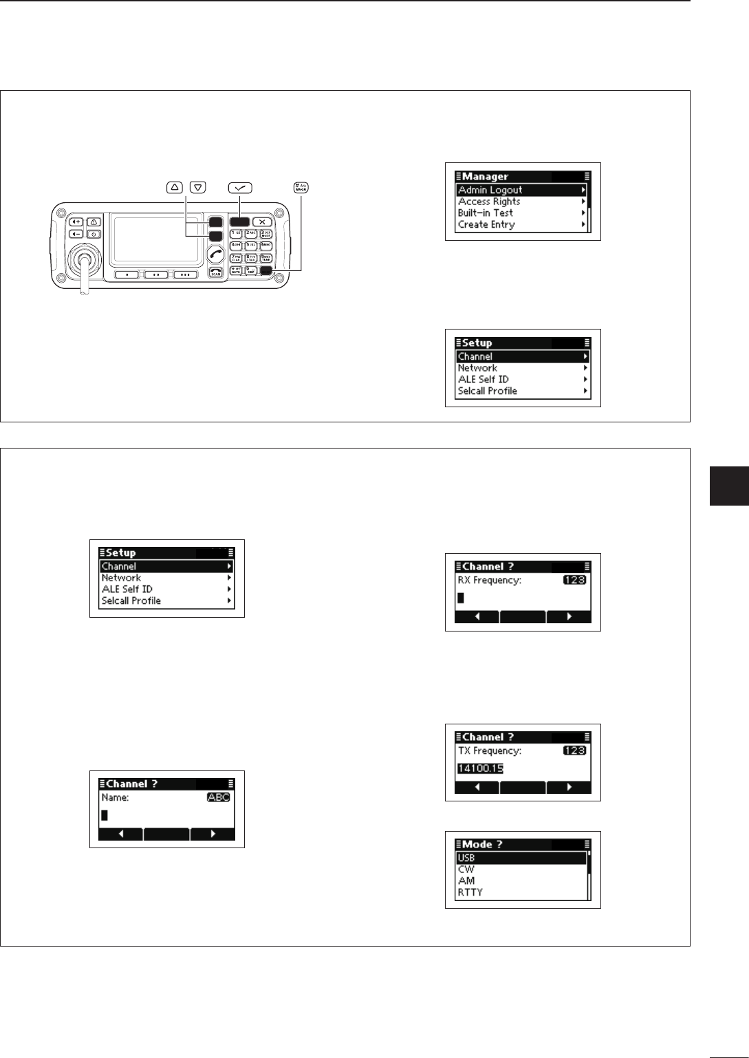
2001 NEW
43
5
MENU SCREEN
1
2
3
4
5
6
7
8
9
10
11
12
13
14
15
16
17
Quick Reference
Setup D
You can make a new entries that are Channel, Net-
work, ALE Self ID or Selcall Profile using the Setup
Wizard.
/
Push q[MNGR](#) to enter the Manager Menu
screen.
• “Admin Logout” is automatically selected.
Push w[r] or [s] to select “Setup,” and then push
[4].
Create the desired entry as follows. e
• “Channel,” “Network,” “ALE Self ID,” or “Selcall Profile”
can be selected.
•Channel
A new memory channel can be created.
Push q[r] or [s] to select “Channel,” and then hold
down [4] for 1 second to enter the input mode.
Push Keypad to enter the Channel name, and then w
push [4].
• Up to 20 characters can be entered.
• See page 2 for the usable characters details.
• Push [A/a](#) to toggle between the Upper, Lower case
letter input modes and Number input mode.
• Push [8] to delete the character, symbol or number to
the left of the cursor.
• Push [t](§) or [u](§§§) to move the cursor.
Push Keypad to enter the receive frequency, and e
then push [4].
• Push [M] to enter the decimal point.
• Push [8] to delete the number.
• Push [t](§) or [u](§§§) to move the cursor.
Push Keypad to enter the transmit frequency, and r
then push [4].
• Push [M] to enter the decimal point.
• Push [8] to delete the number.
• Push [t](§) or [u](§§§) to move the cursor.
Push t[r] or [s] to select the operating mode.
Push y[4] to save the channel and exit.
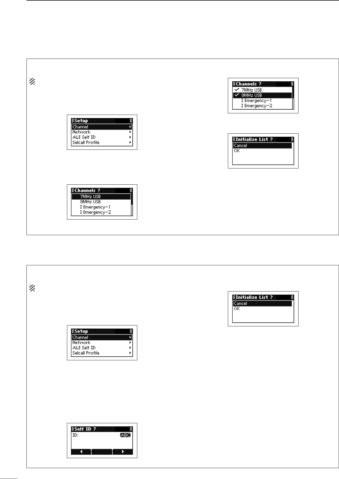
44
5MENU SCREEN
2001 NEW
Manager Menu ■
Setup (Continued) D
•Network
A new network can be created.
NOTE: The present Network list is cleared.
Push q[r] or [s] to select “Network,” and then hold
down [4] for 1 second to enter the input mode.
Push w[r] or [s] to select the memory channels,
and then push [4] to select or deselect.
• “4” appears to the left of the selected channel.
• If desired, several channels can be selected.
Hold down e[4] for 1 second to go to the next
screen.
Push r[s] to select “OK,” and then push [4].
• If desired, select “Cancel” and then push [4].
•ALESelfID
A Self ID can be created.
NOTE: The present Self ID is cleared.
Push q[r] or [s] to select “ALE Self ID,” and then
hold down [4] for 1 second to enter the input
mode.
Push Keypad to enter the desired ID, and then w
push [4].
• Usable characters are A to Z, 0 to 9, ? and @.
• Push [A/a](#) to toggle between the Alphabet (Upper
case letter) input mode and Number input mode.
• Push [8] to delete the character, symbol or number to
the left of the cursor.
• Push [t](§) or [u](§§§) to move the cursor.
Push e[s] to select “OK,” and then push [4].
• If desired, select “Cancel” and then push [4].
2001 NEW
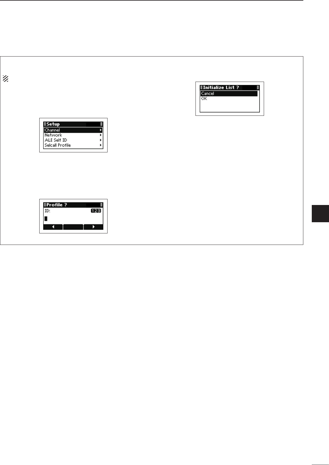
2001 NEW
45
5
MENU SCREEN
1
2
3
4
5
6
7
8
9
10
11
12
13
14
15
16
17
Quick Reference
•SelcallProle
Selcall Profile can be created.
NOTE: The present Selcall Profile is cleared.
Push q[r] or [s] to select “Selcall Profile,” and
then hold down [4] for 1 second to enter the input
mode.
Push Keypad to enter the desired ID, and then w
push [4].
• Up to 6 numbers can be entered.
• Usable characters are A to Z, 0 to 9, ? and @.
• Push [8] to delete the number to the left of the cursor.
• Push [t](§) or [u](§§§) to move the cursor.
Push e[s] to select “OK,” and then push [4].
• If desired, select “Cancel” and then push [4].
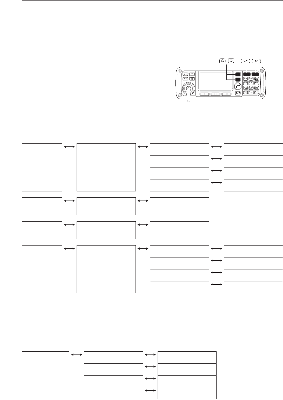
46
5MENU SCREEN
2001 NEW
Main Menu ■
Entering the Main Menu D
Push q[8] to enter the Main Menu screen.
Push w[r] or [s] to select the item, and then push
[4] to open the screen.
• “ALE,” “Call In,” “Call Out,” “Channel,” “Network,” “Selcall,”
“Setmode” or “VFO” can be selected.
• If desired, push [8] to returns to the Memory channel
screen.
Push e[r] or [s] to select the item, and then push or
hold down [4] to display or edit the screen.
/
ALE D
Displays or edits the Entry of the list that is related to ALE.
While displaying an Entry, hold down [4] for 1 second to enter the programing mode.
Call ID Call ID
Displays the prepro-
grammed Call ID list.
ID
Displays the ID. ID editing mode
NET ID
Displays the NET ID. NET ID selection mode
Network
Displays the Network. Network selection mode
Slot
Displays the Slot. Slot selection mode
Message Message
Displays the prepro-
grammed Message list.
Message editing mode
NET ID NET ID
Displays the prepro-
grammed NET ID list.
NET ID editing mode
Self ID Self ID
Displays the prepro-
grammed Self ID list.
ID
Displays the ID. ID editing mode
NET ID
Displays the NET ID. NET ID selection mode
Network
Displays the Network. Network selection mode
Slot
Displays the Slot. Slot selection mode
Channel D
Displays or edits the Memory channels.
While displaying an Entry of the memory channel, hold down [4] for 1 second to enter the editing mode.
Memory Channel
Displays the prepro-
grammed Memory
channels.
Name
Displays the Name. Name editing mode
RX frequency
Displays the RX frequency. RX frequency editing
mode
TX frequency
Displays the TX frequency. TX frequency editing mode
Mode
Displays the Mode. Mode editing mode
Call In/Call Out D
Displays the Entry of the Call In (Received Call) or Call Out (Send Call).
2001 NEW
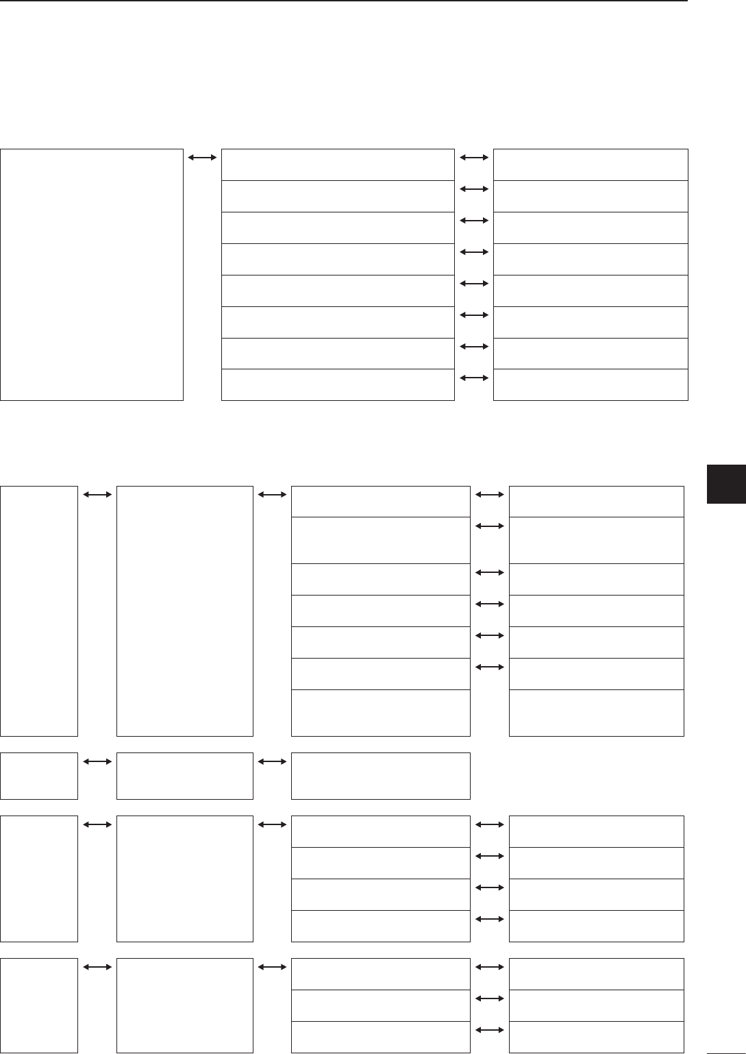
2001 NEW
47
5
MENU SCREEN
1
2
3
4
5
6
7
8
9
10
11
12
13
14
15
16
17
Quick Reference
Selcall D
Displays or edits the Entry of the list that related to Selcall.
While displaying an Entry, hold down [4] for 1 second to enter the programing mode.
Address Address
Displays the prepro-
grammed Address list.
Name
Displays the ID. Name editing mode.
Type/ID
Displays the Call type and ID or
number.
Call type selection and ID or
number editing mode.
Network
Displays the Network. Network selection mode.
Channel
Displays the Channel. Channel selection mode.
Phone Link
Displays the Phone Link. Phone Link selection mode.
Message
Displays the Message. Message selection mode.
Emergency Link
Displays the Emergency Link
setting ON or OFF.
Emergency Link setting mode.
Message Message
Displays the prepro-
grammed Message list.
Message editing mode
Phone Link Phone Link
Displays the prepro-
grammed Phone Link
list.
Name
Displays the ID. Name editing mode.
ID
Displays the ID. ID editing mode.
Network
Displays the Network. Network selection mode.
Channel
Displays the Channel. Channel selection mode.
Profile Profile
Displays the prepro-
grammed Profile list.
Name
Displays the ID. Name editing mode.
ID
Displays the ID. Call type selection and ID or
number editing mode.
Network
Displays the Network. Network selection mode.
Network D
Displays or edits the Entry of the Network list.
While displaying an Entry, hold down [4] for 1 second to enter the editing mode.
Network
Displays the preprogrammed
Network list.
Name
Displays the Name. Name editing mode.
Scan Type
Displays the Scan Type. Scan Type selection mode.
Call System
Displays the Call System. Call System selection mode.
Call Detect Time
Displays Detected Time. Call Detect Time selection mode.
Preamble
Displays the Preamble time. Preamble time selection mode.
Sounding Interval
Displays the Sounding Interval. Sounding Interval selection mode.
Priority
Displays the Priority setting ON or OFF. Priority setting mode.
Channels
Displays the selected channel number. Memory channel selection mode.
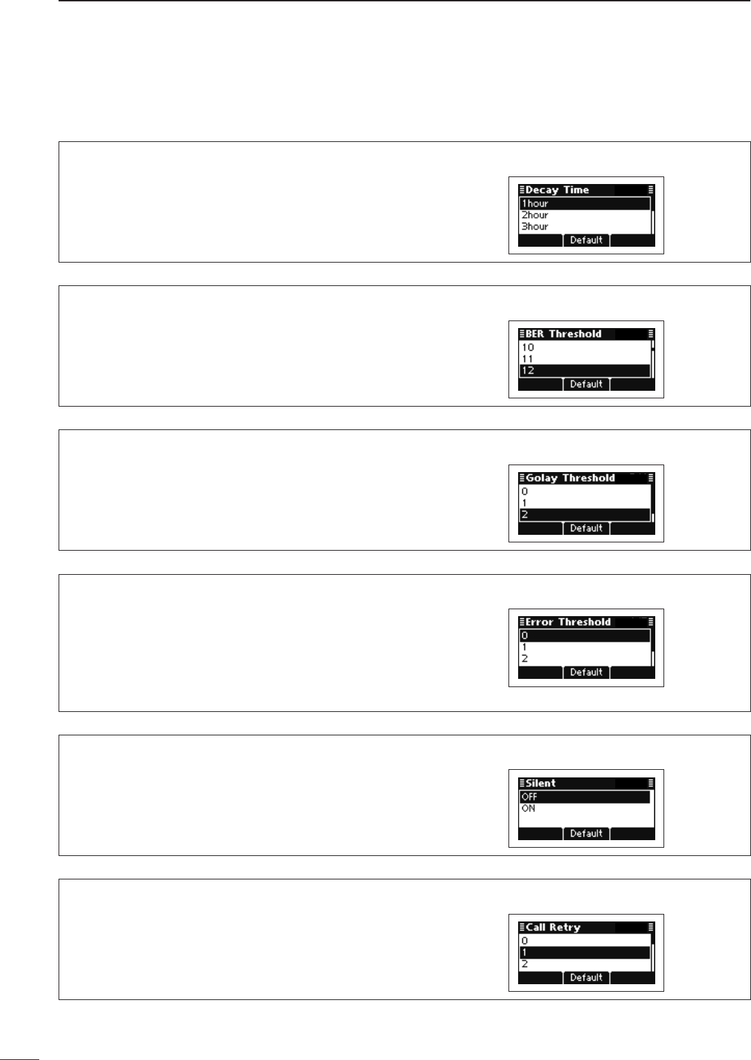
48
5MENU SCREEN
2001 NEW 2001 NEW
ALE Set mode
Decay Time (Default: 1 hour)
Set the decay time for the Auto Sounding function to
between 1 and 8 hours.
BER Threshold (Default: 12)
Set the Bit Error Ratio (BER) threshold level to be-
tween 0 and 48 bits for ALE communication quality.
One unit consists of 48 bits of data.
Golay Threshold (Default: 2)
Set the Golay threshold level to between 0 and 3 bits
for ALE communication quality.
The Golay consists of 12 bits of original data and 12
bits of correction data.
Error Threshold (Default: 0)
Set the Error threshold level to between 0 and 4 for
ALE communication quality.
When errors detected by BER threshold or Golay
threshold are over this setting, communication is not
possible.
Silent (Default: OFF)
Set the ALE Silent mode to ON or OFF.
When set to OFF, the transceiver automatically an-
swers back if your station ID is called. When set to
ON, the transceiver ignores the call.
Call Retry (Default: 1)
Set the retry times to between 0 (OFF) and 10 when
the called station does not answer back.
Setmode D
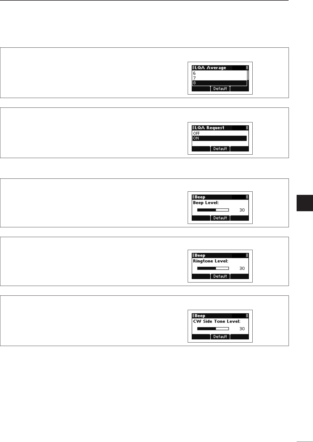
2001 NEW
49
5
MENU SCREEN
1
2
3
4
5
6
7
8
9
10
11
12
13
14
15
16
17
Quick Reference
LQA Average (Default: 8)
Set the adopting number of LQA data for averaging
to between 1 and 8.
LQA Request (Default: ON)
Set the LQA request function to ON or OFF.
When set to ON, the transceiver requests the called
station to send LQA data with an ALE answer back
call.
BEEP Set mode
Beep Level (Default: 30)
Adjust the confirmation beep level to between 0
(OFF) and 50 (Maximum), in 1 digit steps.
Ringtone Level (Default: 30)
Adjust the ringtone level to between 0 (OFF) and 50
(Maximum), in 1 digit steps, to sound ringer tones
when a signal is received.
CW Side Tone Level (Default: 30)
Adjust the CW side tone level to between 0 (OFF)
and 50, in 1 digit steps.
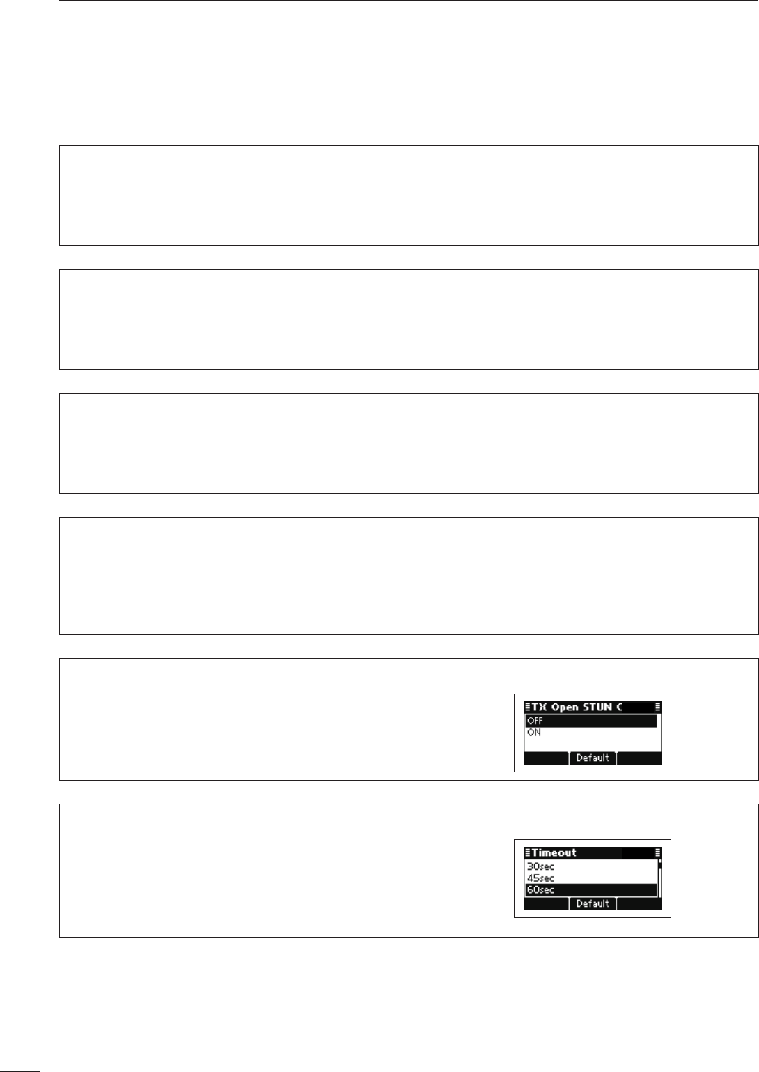
50
5MENU SCREEN
2001 NEW 2001 NEW
Call Set mode
Accept Icom Selcall
This item allows the transceiver to receive and make
Icom Selcalls.
This setting is permanently set to “ON.”
Accept Open Selcall
This item allows the transceiver to receive and make
Open Selcalls.
This setting is permanently set to “ON.”
Accept ALE
This item allows the transceiver to receive and make
ALE (Automatic Link Establishment) calls.
This setting is permanently set to “ON.”
Accept RFDS (Only AUS version)
This item allows the transceiver to receive and make
RFDS (Royal Fling Doctor Service) emergency calls.
This setting is permanently set to “ON” for the AUS
version, or OFF for other versions.
TX Open STUN Call (Default: OFF)
This item allows the transceiver to make STUN calls.
Timeout (Default: 60sec)
Select the RX Timeout timer between 15 and 300
seconds in 15 seconds steps, or OFF.
After transmitting a Get Position or Get Status com-
mand, the transceiver waits for a reply during this set
period.
Setmode D(Continued)
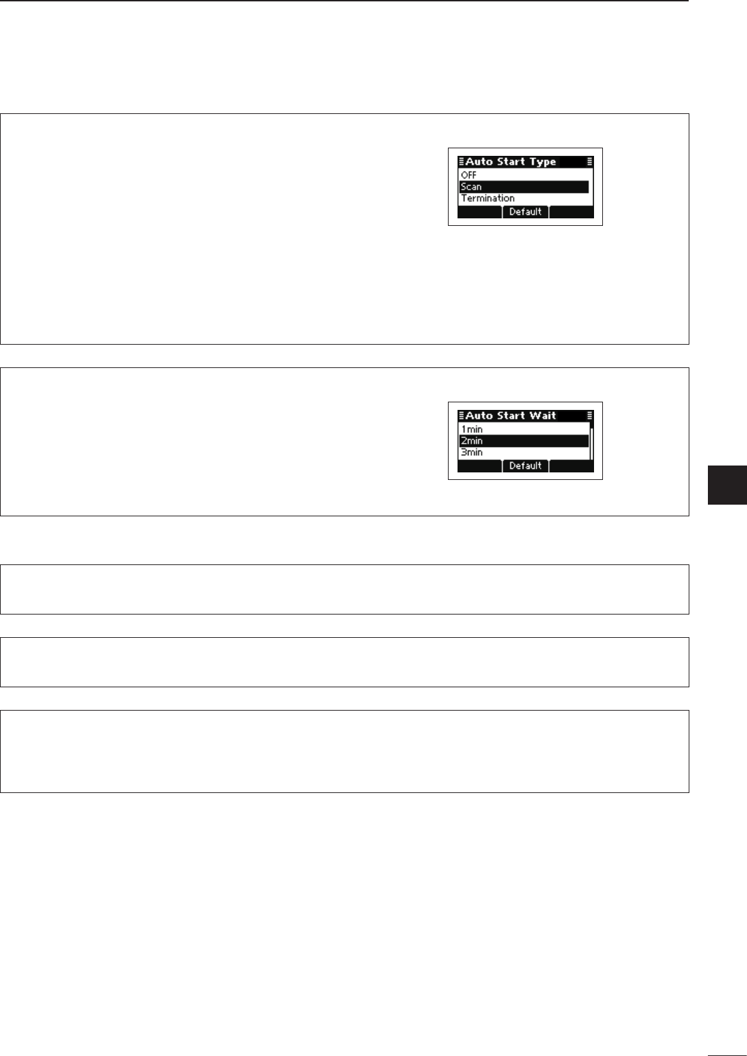
2001 NEW
51
5
MENU SCREEN
1
2
3
4
5
6
7
8
9
10
11
12
13
14
15
16
17
Quick Reference
Auto Start Type (Default: Scan)
Select the Auto Start Type.
If no operation occurs during the Auto Start Wait Time
period, the Selected function automatically starts.
OFF: The Auto Start function is disabled.
Scan: The transceiver automatically cancels
the Handshake status, and then the
scan starts.
Termination: The transceiver automatically cancels
the Handshake status.
The Auto Start Wait Time is set in the next item.
Auto Start Wait Time (Default: 2min)
Set the Auto Start Wait timer to between 1 and 20
minutes, in 1 minute steps.
If no operation occurs during this period, the Auto
Start function automatically starts.
The Auto Start function is selected in the previous
item.
Comment Set mode
Customer Name
Enter a customer name of up to 20 characters.
Setting Comment
Enter a comment of up to 20 characters.
Model
This item displays the transceiver’s model name.
The Model is permanently set to “IC-F8101.”
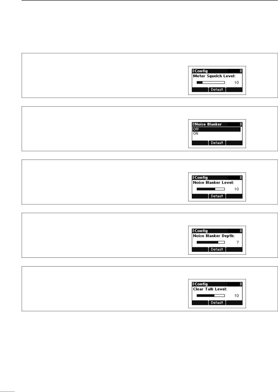
52
5MENU SCREEN
2001 NEW 2001 NEW
Config Set mode
Meter Squelch Level (Default: 10)
Adjust the squelch threshold level to between 0 and
50, in 1 digit steps.
When the S-meter squelch is activated, only signals
stronger than this set level are received.
Noise Blanker (Default: OFF)
Turns the noise blanker function ON or OFF.
The Noise Blanker function eliminates pulse-type
noise such as that from car ignitions.
Noise Blanker Level (Default: 10)
Adjust the Noise blanker level to between 0 and 15,
in 1 digit steps.
The set level is effective when the Noise Blanker is
activated.
Noise Blanker Depth (Default: 7)
Adjust the Noise blanker depth to between 0 and 9,
in 1 digit steps.
The set level is effective when the Noise Blanker is
activated.
Clear Talk Level (Default: 10)
The Clear Talk function adjusts signals in the pres-
ence of noise using the DSP circuit. This item adjusts
the Clear Talk Level to between 1 (Minimum) and 15
(Maximum).
Setmode D(Continued)
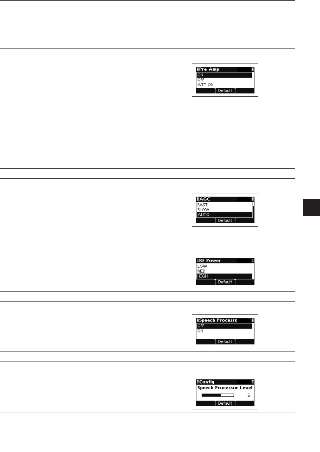
2001 NEW
53
5
MENU SCREEN
1
2
3
4
5
6
7
8
9
10
11
12
13
14
15
16
17
Quick Reference
Pre Amp (Default: ON)
Turn ON the Preamplifier function or Attenuator func-
tion.
ON: Turns ON the Preamplifier function, which
amplifies received signals in the receiver
front end, to improve the S/N ratio and the
sensitivity.
OFF: Turns OFF both functions.
ATT ON: Turns ON the Attenuator function, which
prevents a desired signal from being
distorted when very strong signals are
near the desired frequency, or when very
strong electromagnetic fields, such as
from broadcast stations, are near your lo-
cation.
AGC (Default: AUTO)
Set the Automatic gain control settings to FAST,
SLOW, AUTO or OFF.
RF Power (Default: HIGH)
Set the transmit output power to LOW, MID or HIGH.
Speech Processor (Default: OFF)
Turns the Speech Processor function ON or OFF.
Speech Processor Level (Default: 6)
Adjust the Speech Processor Level to between 0
(Minimum) and 10 (Maximum), in 1 digit steps.
The set level is effective only when the Speech Pro-
cessor is turned ON.
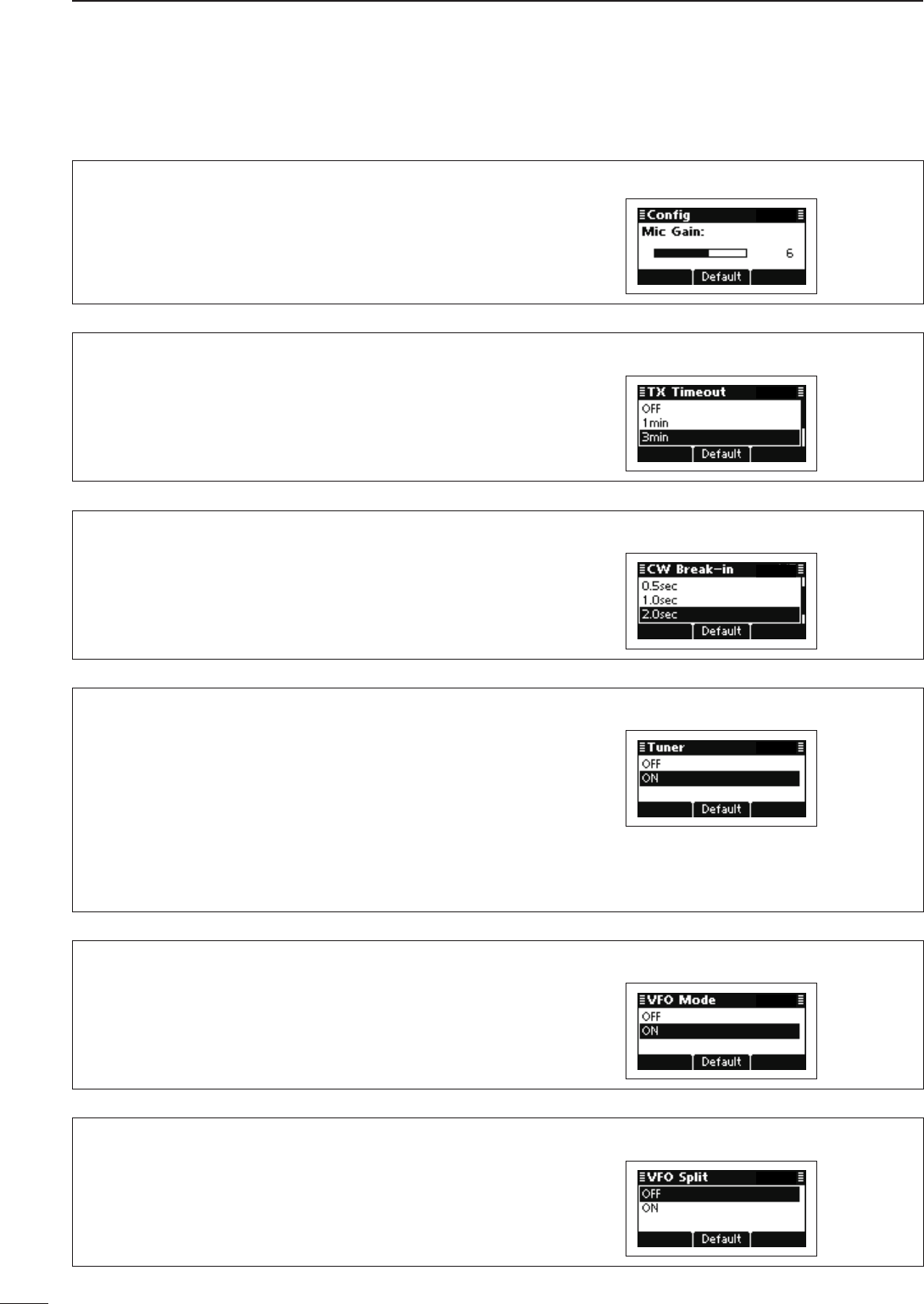
54
5MENU SCREEN
2001 NEW 2001 NEW
Setmode D
Config Set mode (Continued)
Mic Gain (Default: 6)
Adjust the Microphone gain to between 0 (Minimum)
and 10 (Maximum), in 1 digit steps.
TX Timeout (Default: 3min)
Set the Time-Out Timer function time to 1, 3, 5 or
10 minutes, or OFF. If a continuous transmission ex-
ceeds the set time period, transmitting will be cut off.
CW Break-in (Default: 2.0sec)
The CW Break-In function toggles transmit and re-
ceive with your CW keying. This allows you to mute
receiving the time delay ends after you stop keying.
Turn ON the CW Break-In function and set the delay
to 0.5, 1, 2 or 3 seconds, or OFF.
Tuner (Default: ON)
Turns the automatic antenna tuner ON or OFF.
If you use an optional AT-140, AH-740 or AH-760,
select “ON.”
OFF: The antenna tuner is disabled and is by-
passed.
ON: The automatic antenna tuner can be used
when the transceiver enters the antenna
tune mode.
VFO mode (Default: ON)
Select ON or OFF to activate the VFO mode.
VFO Split (Default: OFF)
Turns the Split frequency operation in the VFO mode
ON or OFF.
Split frequency operation allows you to transmit and
receive on two different frequencies between VFO A
and VFO B.
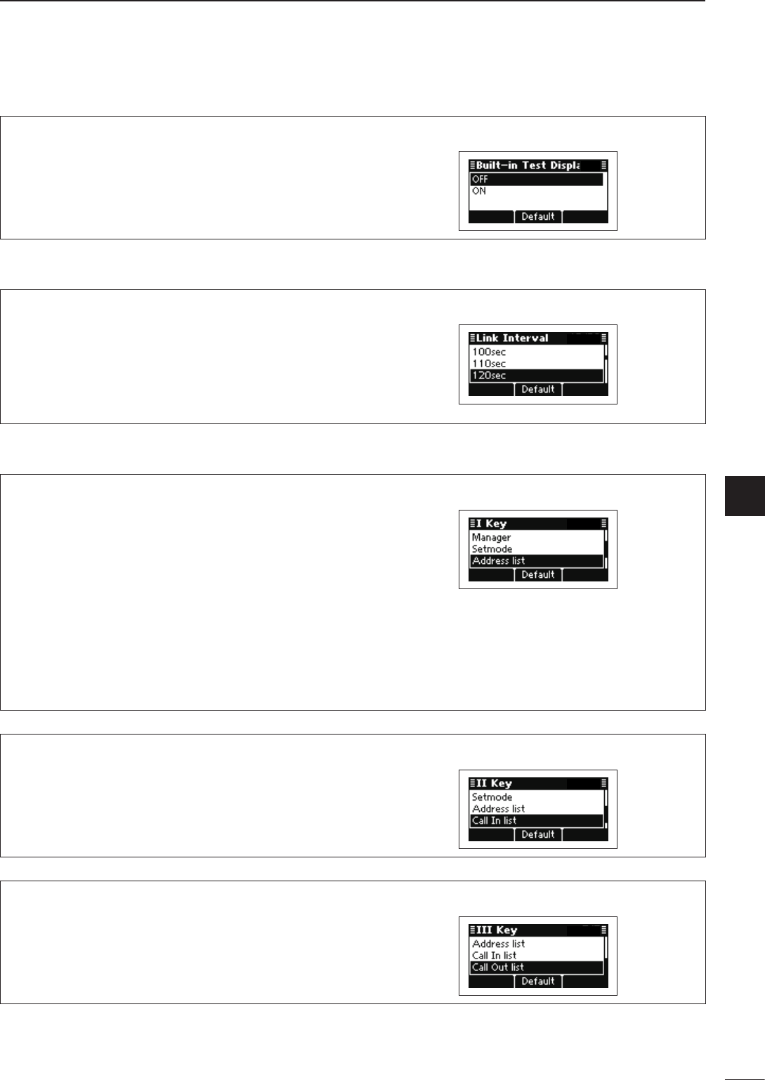
2001 NEW
55
5
MENU SCREEN
1
2
3
4
5
6
7
8
9
10
11
12
13
14
15
16
17
Quick Reference
Built-in Test Display (Default: OFF)
Select whether or not to display the device check
screen after turning ON power. (Default: OFF)
Emergency Set mode
Link Interval (Default: 120sec)
Set the Emergency Link interval time period to be-
tween 10 and 300 seconds, in 10 seconds steps.
The transceiver will sequentially send Emergency
calls to the stations whose “Emergency Link” item is
set to ON in Address of the SELCALL.
Key Set mode
I Key (Default: Address)
The functions listed below can be set to the [I] key.
Not assign: No function.
Menu: Push to enter the Main Menu screen.
Manager: Push to enter the Manager Menu
screen.
Setmode: Push to enter the Setmode screen.
Address list: Push to display the Selcall address
list.
Call In list: Push to display the RX history
screen.
Call Out list: Push to display the TX history screen.
II Key (Default: Call In list)
The functions listed in the “I Key” item can be set to
the [II] key.
III Key (Default: Call Out list)
The functions listed in the “I Key” item can be set to
the [III] key.
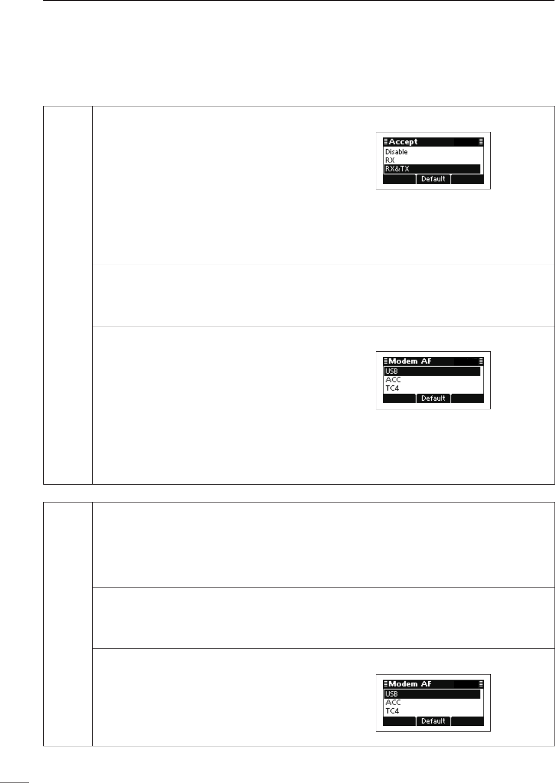
56
5MENU SCREEN
2001 NEW 2001 NEW
Mode Set mode
LSB Accept (Default: Disable for AUS, RX & TX for others)
Set the LSB mode to “Disable,” “RX” or
“RX & TX.”
Disable: Disables the transceiver from
both receiving and transmit-
ting calls.
RX: Allows the transceiver to re-
ceive calls, but disables it from
transmitting them.
RX & TX: Allows the transceiver to both
receive and transmit calls.
Band Width
Displays the IF filter passband width.
The width is permanently set to “3000Hz.”
Modem AF (Default: USB)
Set the connector for data modulation
input when an external unit’s [PTT] is
pushed.
TC4: Inputs the modulation signals
through a RapidM TC4 HF
Data Modem Module.
ACC: Inputs the modulation signals
through the ACC connector.
USB: Inputs the modulation signals
through a USB port.
USB Accept
Displays the USB mode permission set-
ting.
This setting is permanently set to “RX &
TX.”
Band Width
Displays the IF filter passband width.
The width is permanently set to “3000Hz.”
Modem AF (Default: USB)
Set the connector for data modulation
input when an external unit’s [PTT] is
pushed.
See the “Modem AF” item in “LSB” for de-
tails.
Setmode D(Continued)
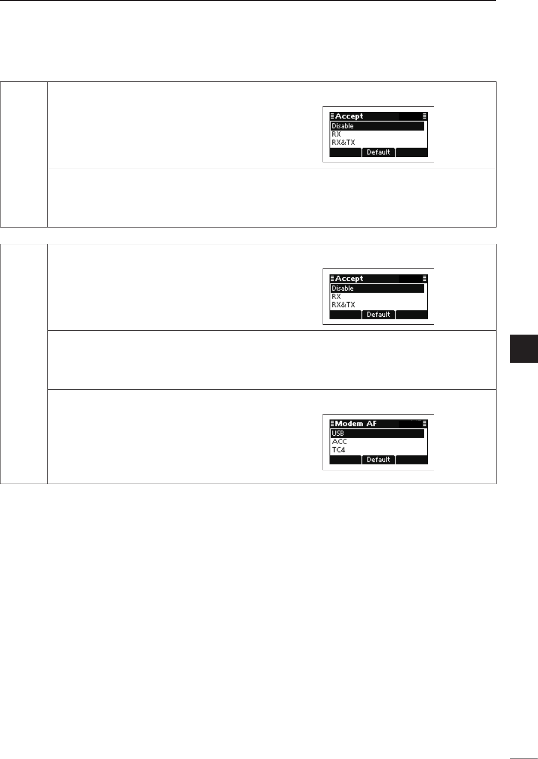
2001 NEW
57
5
MENU SCREEN
1
2
3
4
5
6
7
8
9
10
11
12
13
14
15
16
17
Quick Reference
CW Accept (Default: Disable)
Set the CW mode to “Disable,” “RX” or “RX
& TX.”
See the “Accept” item in “LSB” for details.
Band Width
Displays the IF filter passband width.
The width is permanently set to “500Hz.”
AM Accept (Default: RX for AUS, Disable for others)
Set the AM mode to “Disable,” “RX” or “RX
& TX.”
See the “Accept” item in “LSB” for details.
Band Width
Displays the IF filter passband width.
The width is permanently set to “8000Hz.”
Modem AF (Default: USB)
Set the connector for data modulation
input when an external unit’s [PTT] is
pushed.
See the “Modem AF” item in “LSB” for de-
tails.
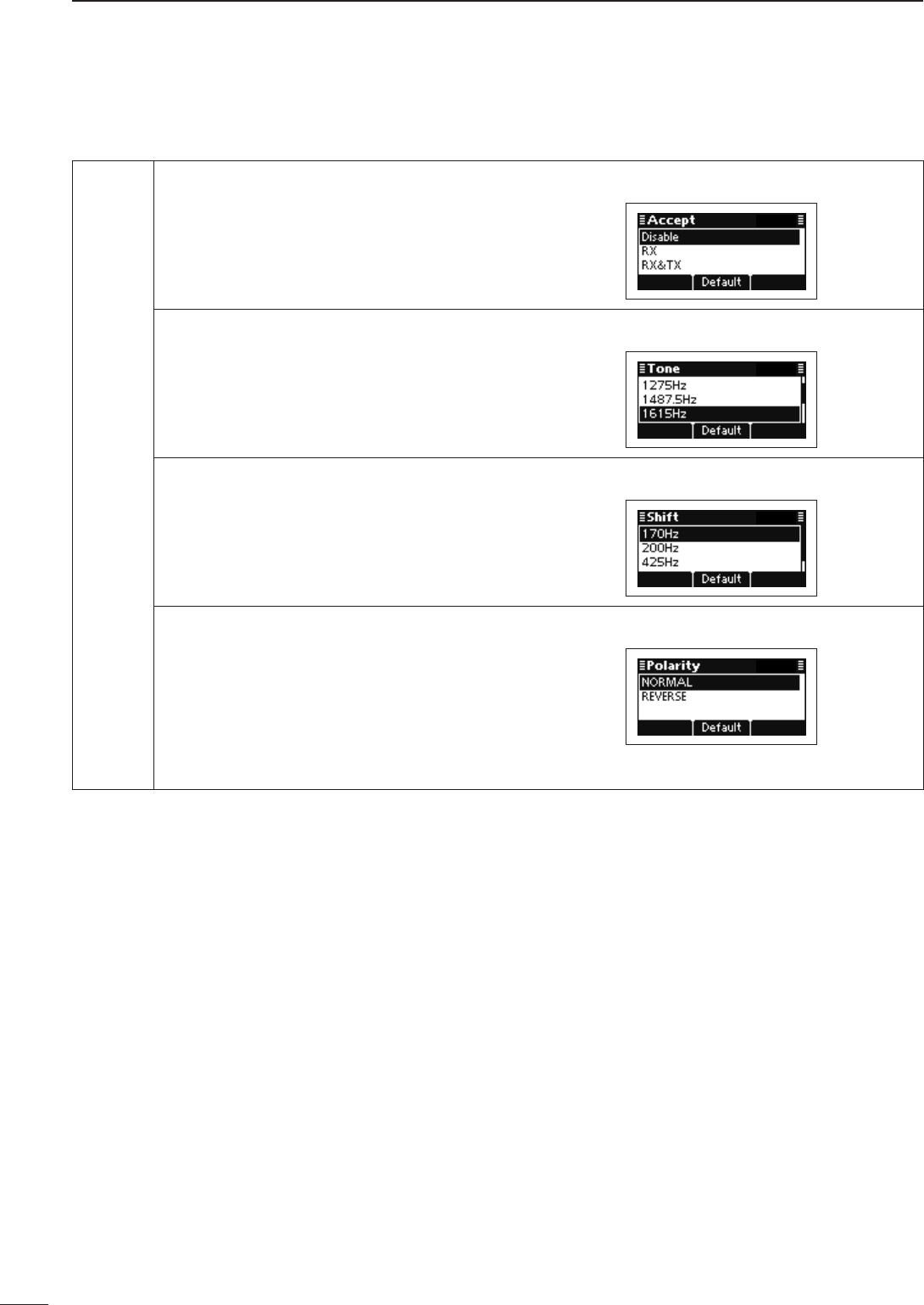
58
5MENU SCREEN
2001 NEW 2001 NEW
Setmode D
Mode Set mode (Continued)
RTTY Accept (Default: Disable)
Set the RTTY mode to “Disable,” “RX” or
“RX & TX.”
See the “Accept” item in “LSB” for details.
Tone (Default: 1615Hz)
Set the RTTY mark frequency to 1200,
1275, 1487.5, 1615, 1700, 2100 or 2125
Hz.
Shift (Default: 170Hz)
Set the RTTY shift frequency to 170, 200,
425 or 850 Hz.
Polarity (Default: Normal)
Set the keying polarity to Normal or Re-
verse.
When reverse polarity is selected, the mark
and space frequencies are reversed.
Normal: Key open/close = Mark/Space
Reverse: Key open/close = Space/Mark
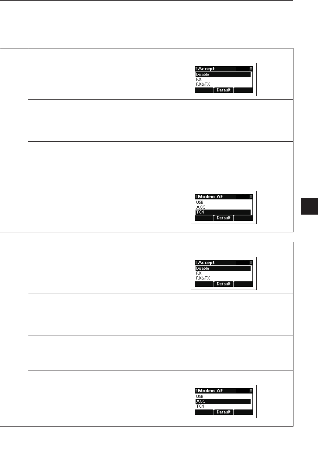
2001 NEW
59
5
MENU SCREEN
1
2
3
4
5
6
7
8
9
10
11
12
13
14
15
16
17
Quick Reference
LSBD1 Accept (Default: Disable)
USBD1 Set the LSBD1 or USBD1 mode to “Dis-
able,” “RX” or “RX & TX.”
See the “Accept” item in “LSB” for details.
Offset
Displays the Offset frequency.
The frequency is permanently set to
“1800Hz.”
Band Width
Displays the IF filter passband width.
The width is permanently set to “3000Hz.”
Modem AF (Default: TC4)
Set the connector for data modulation
input when an external unit’s [PTT] is
pushed.
See the “Modem AF” item in “LSB” for de-
tails.
LSBD2 Accept (Default: Disable)
USBD2 Set the LSBD2 or USBD2 mode to “Dis-
able,” “RX” or “RX & TX.”
See the “Accept” item in “LSB” for details.
Offset
Displays the Offset frequency.
The frequency is permanently set to
“1500Hz.”
Band Width
Displays the IF filter passband width.
The width is permanently set to “3000Hz.”
Modem AF (Default: ACC)
Set the connector for data modulation
input when an external unit’s [PTT] is
pushed.
See the “Modem AF” item in “LSB” for de-
tails.
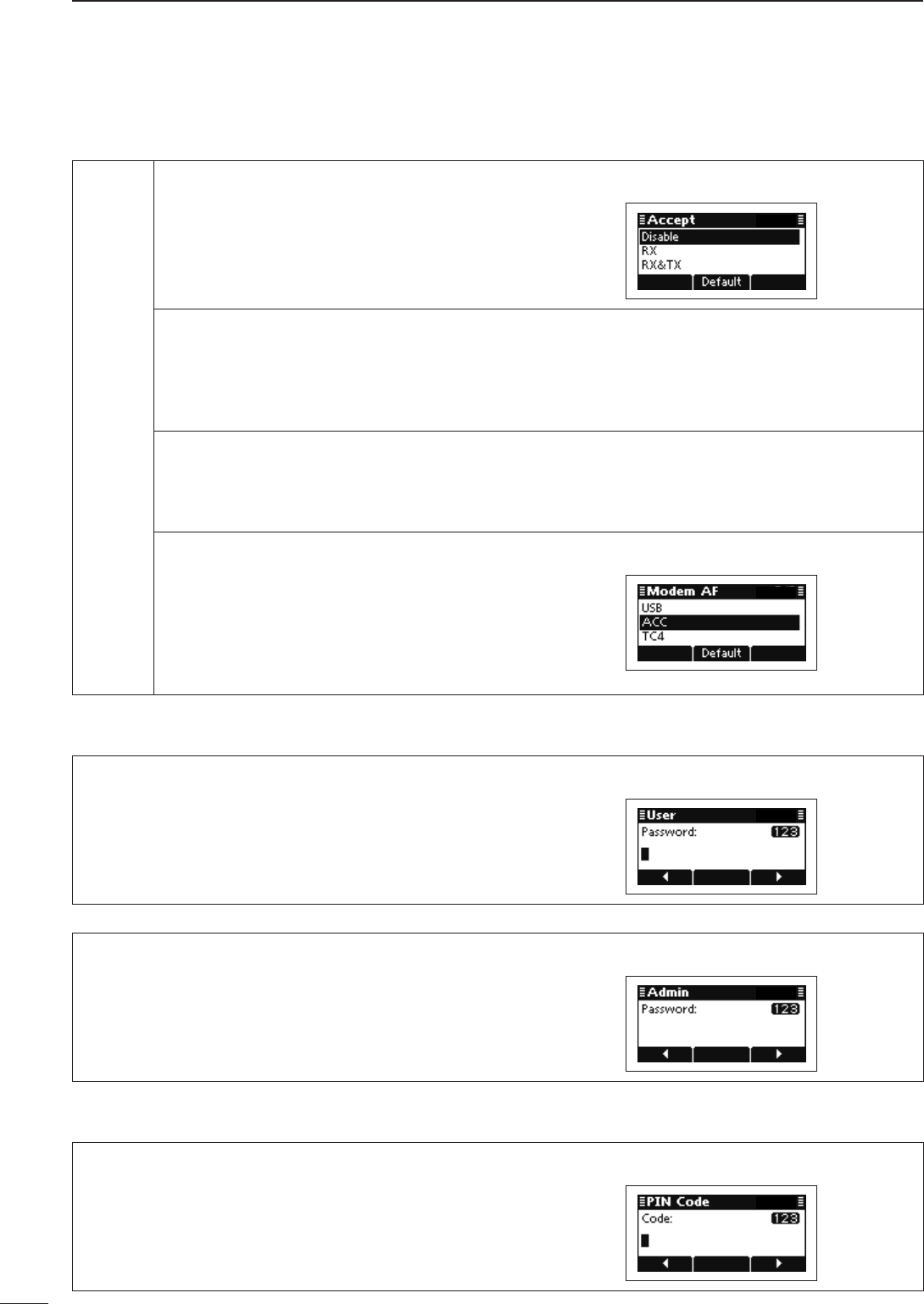
60
5MENU SCREEN
2001 NEW 2001 NEW
Setmode D
Mode Set mode (Continued)
LSBD3 Accept (Default: Disable)
USBD3 Set the LSBD3 or USBD3 mode to “Dis-
able,” “RX” or “RX & TX.”
See the “Accept” item in “LSB” for details.
Offset
Displays the Offset frequency.
The frequency is permanently set to
“1650Hz.”
Band Width
Displays the IF filter passband width.
The width is permanently set to “3000Hz.”
Modem AF (Default: ACC)
Set the connector for data modulation
input when an external unit’s [PTT] is
pushed.
See the “Modem AF” item in “LSB” for de-
tails.
Password Set mode
User
Enter a Login Password of up to 10 characters to en-
ter the User mode.
Admin
Enter a Login Password of up to 10 characters to en-
ter the Administrator mode.
PIN Code Set mode
PIN Code
Set a PIN code of up to 10 digits.
When the matched Selcall ID and PIN Code are re-
ceived, the stun function is activated.
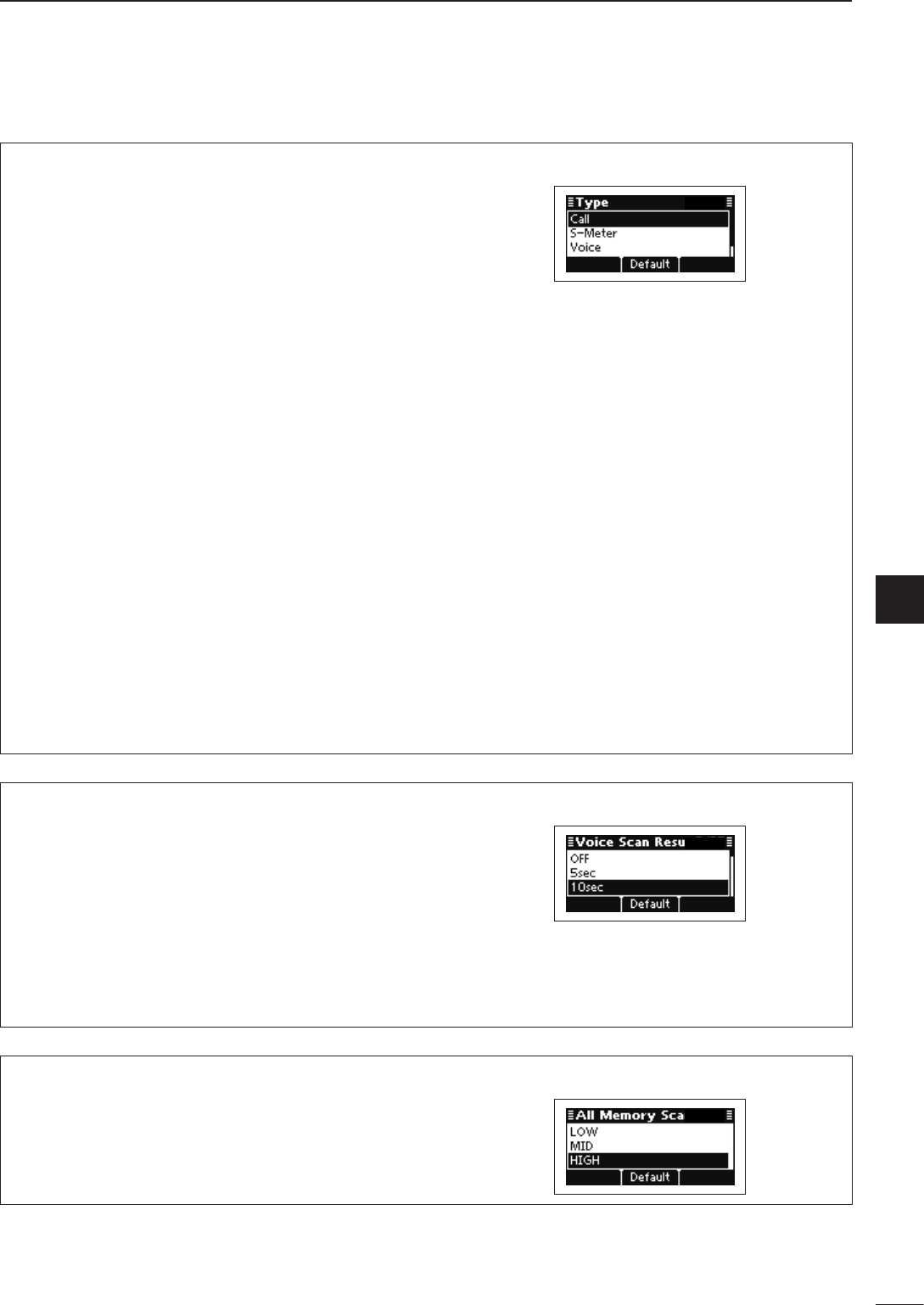
2001 NEW
61
5
MENU SCREEN
1
2
3
4
5
6
7
8
9
10
11
12
13
14
15
16
17
Quick Reference
Scan Set mode
Type (Default: Call)
Set the scan type to “Call,” “S-Meter,” “Voice” or “All
Memory.” (Default: Call)
CALL: Call Scan. It scans the channels that be-
long to the network group whose scan
type is “Call.”
If your station ID is called with a Selcall or
ALE call, the scan stops on that channel
and the voice squelch control function is
activated.
S-Meter: S-Meter Scan. It scans the channels that
belong to the network group whose scan
type is “S-Meter.”
If the transceiver detects the signal whose
S-meter level is higher than the Meter
Squelch Level setting, the scan stops on
that channel.
Voice: Voice Scan. It scans the channels that
belong to the network group whose scan
type is “Voice.”
If the transceiver detects voice compo-
nents, the scan stops on that channel.
All: All Memory Scan. It scans all memory
channels.
If the transceiver detects signal whose
S-meter level is higher than the Meter
Squelch Level setting, the scan stops on
that channel.
Voice Scan Resume (Default: 10sec)
Set the scan resume function to ON or OFF for an S-
Meter, Voice or All Memory scan, and set the pause
timer to between 5 seconds and 120 seconds, in 5
second steps. (Default: 10sec)
When this setting is ON and a signal is detected, a
scan pauses for this set period, then resumes, or re-
sumes 2 seconds after the signal disappears.
If OFF is selected, the scan pauses until the signal
disappears.
All Memory Scan Speed (Default: HIGH)
Set the scan speed for the All Memory scan to LOW,
MID or HIGH. (Default: HIGH)
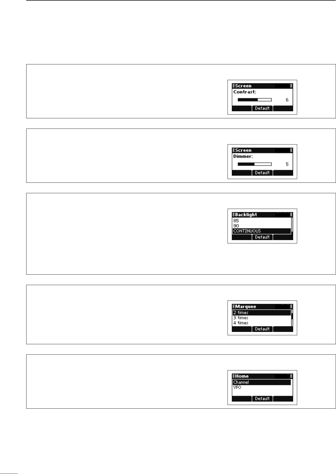
62
5MENU SCREEN
2001 NEW 2001 NEW
Screen Set mode
Contrast (Default: 6)
Adjust the contrast of the LCD to between 0 and 10,
in 1 digit steps.
Dimmer (Default: 5)
Adjust the backlight brightness of the LCD to between
0 (dark) and 10 (bright), in 1 digit steps.
1 to 10: Lights while the transceiver power is ON.
0: Turns OFF the backlight.
Backlight (Default: CONTINUOUS)
Set the LCD backlight timer to OFF, Continuous, or to
between 5 and 90 seconds, in 5 second steps.
OFF: Never lights.
5 to 90: Lights when an operation is per-
formed, goes out after the specified
time period.
CONTINUOUS: Lights continuously while the trans-
ceiver power is ON.
Marquee (Default: 2 times)
Set the marquee times for the text scroll function.
OFF: Turns OFF the function.
1 time to 7 times: Scrolls the text for the selected
number of times.
CONTINUOUS: Continuously scrolls the text.
Home (Default: Channel)
Select the default home display.
Channel: The contents of the Channel sheet is dis-
played.
VFO: The operating frequency is displayed.
Setmode D(Continued)
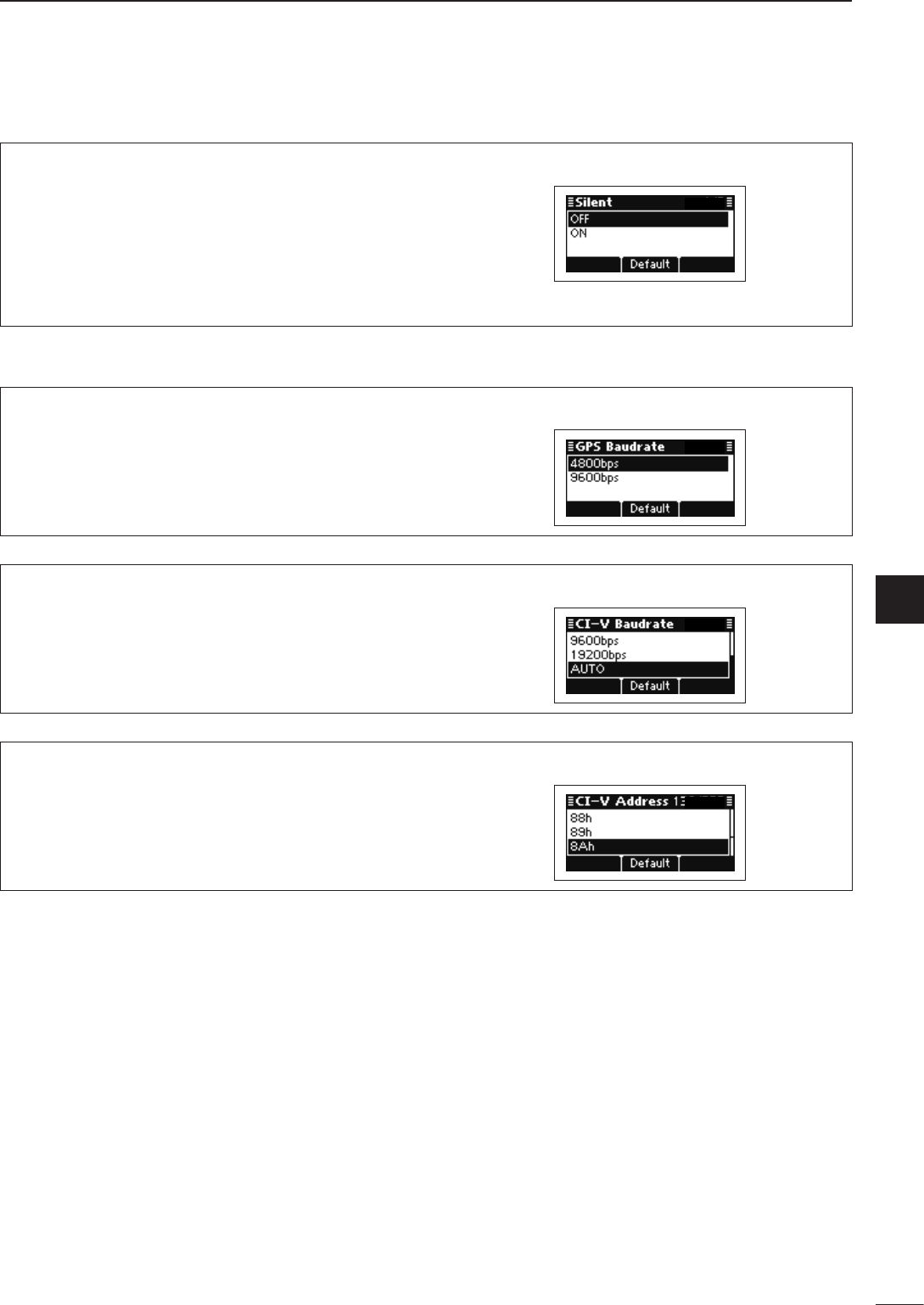
2001 NEW
63
5
MENU SCREEN
1
2
3
4
5
6
7
8
9
10
11
12
13
14
15
16
17
Quick Reference
Selcall Set mode
Silent (Default: OFF)
Set the automatic answer back function for Selcall to
ON or OFF.
OFF: The transceiver automatically answers back if
your station ID is called.
ON: T he transceiver ignores the call even if your
station ID is called.
Serial Port Set mode
GPS Baudrate (Default: 4800)
Set the GPS data transfer speed to 4800 or 9600
bps.
CI-V Baudrate (Default: AUTO)
Set the CI-V data transfer speed to 300, 1200, 4800,
9600, 19200 or AUTO.
When “AUTO” is selected, the baud rate is automati-
cally set according to the data rate of the controller
CI-V Address (Default: 8Ah)
To distinguish equipment, each CI-V transceiver has
its own Icom standard address in hexadecimal code.
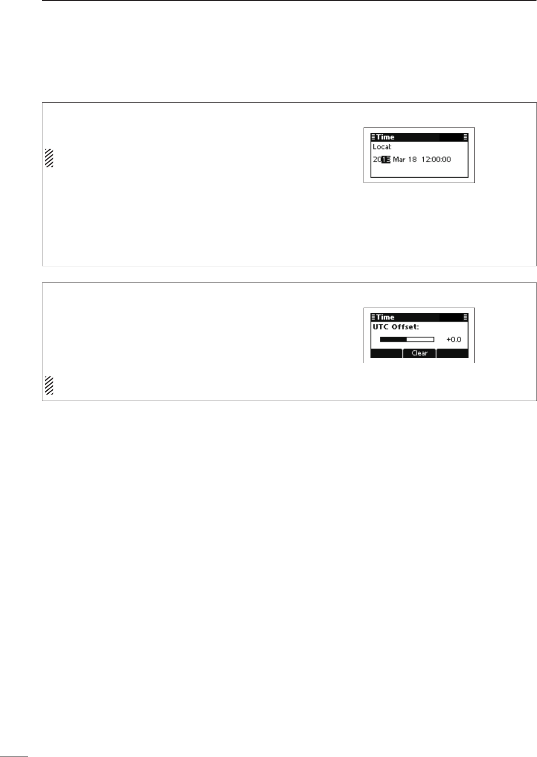
64
5MENU SCREEN
2001 NEW 2001 NEW
Time Set mode
Local
Set the Local time.
Before programming this item, the “UTC Offset”
item must be set.
Push q[r] or [s] to select this item, and then hold
down [4] to open the programming screen.
Push w[r] or [s] to select the digit.
• Push [4] to move the cursor right, push [8] to move
the cursor left.
After the ‘second’ digit is programmed, push e[4] to
set the time and return to the previous screen.
UTC Offset
Select the time difference between UTC (Universal
Time Coordinated) and the local time.
–12.0 to + 12.0 (in 0.5* steps)
* 0.5 = 30 minutes
This item must be set before programming the “Lo-
cal” item.
Setmode D(Continued)

2001 NEW
65
5
MENU SCREEN
1
2
3
4
5
6
7
8
9
10
11
12
13
14
15
16
17
Quick Reference
If you want to initialize the operating settings in the
Main Menu, without clearing memory channel con-
tents or ID contents, do the following steps.
q Turn OFF the transceiver power, if it is powered
ON.
w While holding down [r] and [s], and push [] to
turn ON the transceiver power to reset the CPU.
/
■ CPU Reset
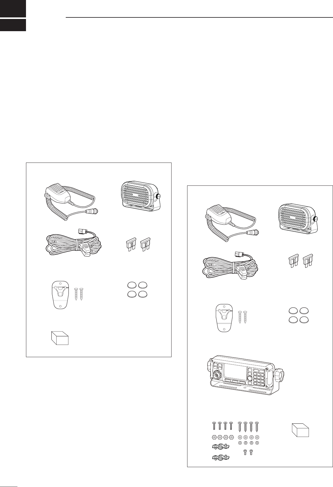
6
66
CONNECTION AND INSTALLATION
2001 NEW 2001 NEW2001 NEW
■ Supplied accessories
er
y
t
u
qw
e
yt
u
qw
io
r
D One package type
The following accessories are supplied with IC-F8101
One package type.
q Microphone ........................................................... 1
w External speaker ................................................... 1
e DC power cable..................................................... 1
r Spare fuses (ATC 30 A) ........................................ 2
t Microphone hanger kit .................................... 1 set
y Rubber feet ........................................................... 4
u Sponge .................................................................. 1
D Separated Type
The following accessories are supplied with IC-F8101
Separated type.
q Microphone ........................................................... 1
w External speaker ................................................... 1
e DC power cable..................................................... 1
r Spare fuses (ATC 30 A) ........................................ 2
t Microphone hanger kit .................................... 1 set
y Rubber feet ........................................................... 4
u Remote controller with mounting bracket .............. 1
i Separation kit* ................................................. 1 set
o Sponge .................................................................. 1
* The separation cable is not supplied, and must be pur-
chased separately according to the cable length.
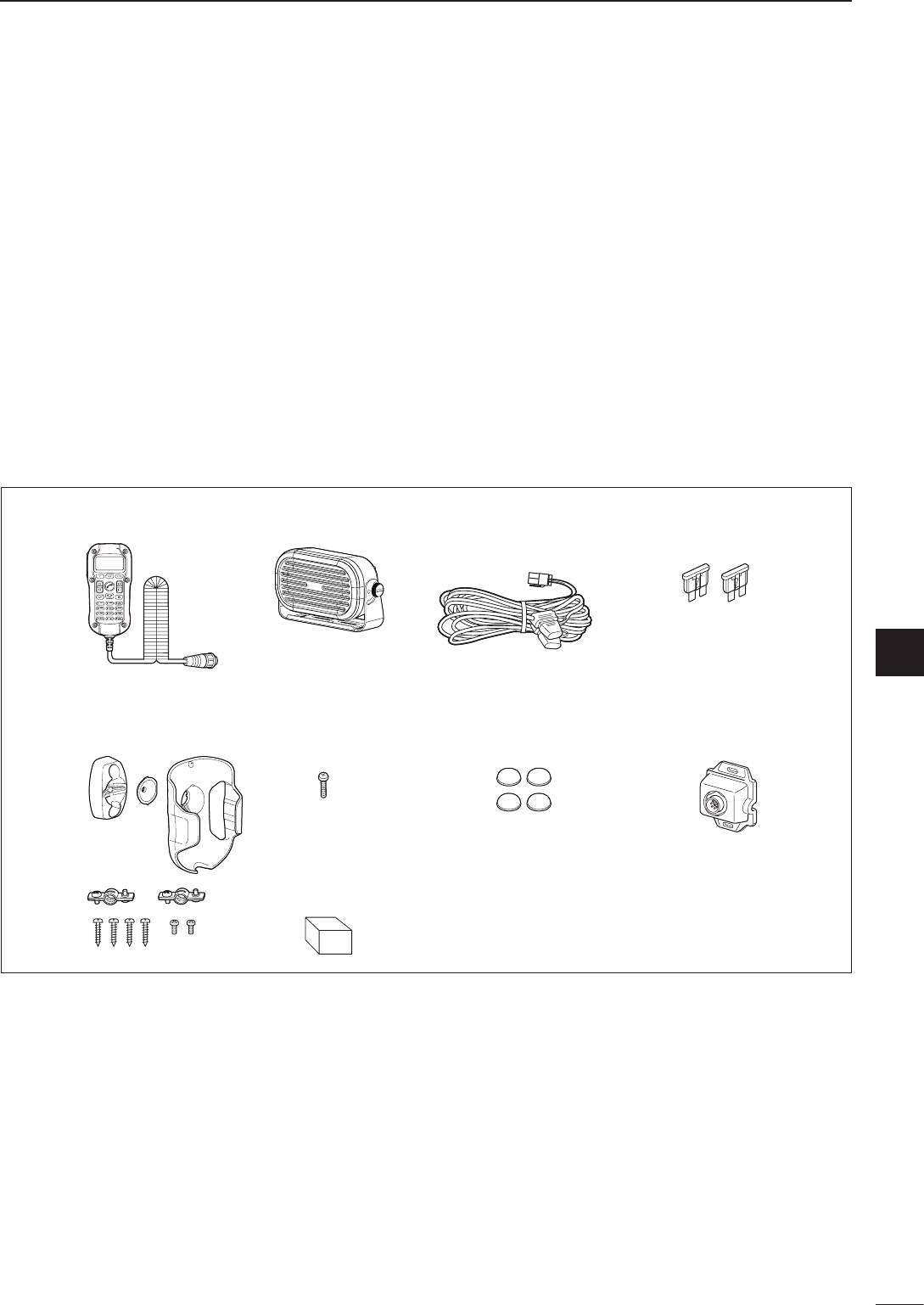
2001 NEW
67
6
CONNECTION AND INSTALLATION
2001 NEW
1
2
3
4
5
6
7
8
9
10
11
12
13
14
15
16
17
Quick Reference
er
ut iy
qw
o
D Remote control microphone Type
The following accessories are supplied with IC-F8101
Remote control microphone type.
q Remote control microphone .................................. 1
w External speaker ................................................... 1
e DC power cable..................................................... 1
r Spare fuses (ATC 30 A) ........................................ 2
t Microphone hanger kit .................................... 1 set
y Screw .................................................................... 1
u Rubber feet ........................................................... 4
i Separation MIC connector .................................... 1
o Sponge .................................................................. 1
* The separation cable is not supplied, and must be pur-
chased separately according to the cable length.
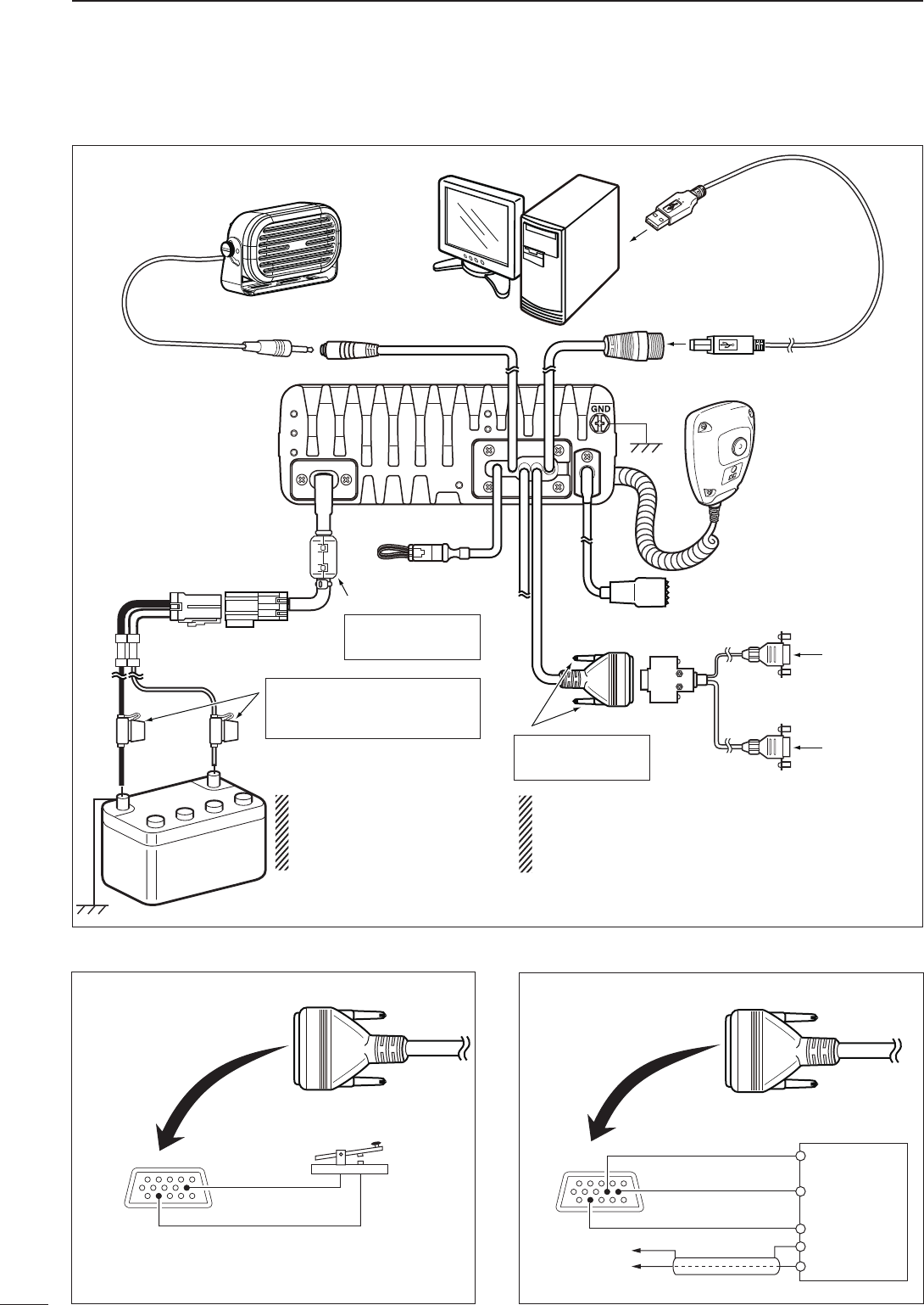
68
6CONNECTION AND INSTALLATION
2001 NEW 2001 NEW
■ Connections
PC
to [USB]
to [ACC]
to a USB port
OPC-2308 GPS unit
D-sub 9 pin
(male)
D-sub 9 pin
(female)
D-sub 15 pin
(female)
Modem unit
to a 13.8 V DC power source
Transceiver
USB cable
(purchase separately)
+ red
_ black
12V
Battery
12V
Battery
R WARNING! NEVER remove
the fuse holders from the black
and red cables.
NEVER remove this
ferrite EMI filter.
NEVER turn these
connector screws.
Only for USA versions
R WARNING! NEVER
connect to a 24 V bat-
tery. This will damage
the transceiver.
Wrap both the antenna and the control cable con-
nectors with rubber vulcanizing tape, and then
wrap electrical tape over the rubber vulcanizing
tape to help in waterproofing.
1
610
5
11 15
12
to IC-F8101
SP connector AF input
FSK terminal unit
AF ground
Tx/Rx control
To pin 12
To pin 10
To pin 9
• FSK connection
[ACC]
FSK keying
Ground
1
6
5
11 15 To pin 12
To pin 10
• CW key connection
[ACC]
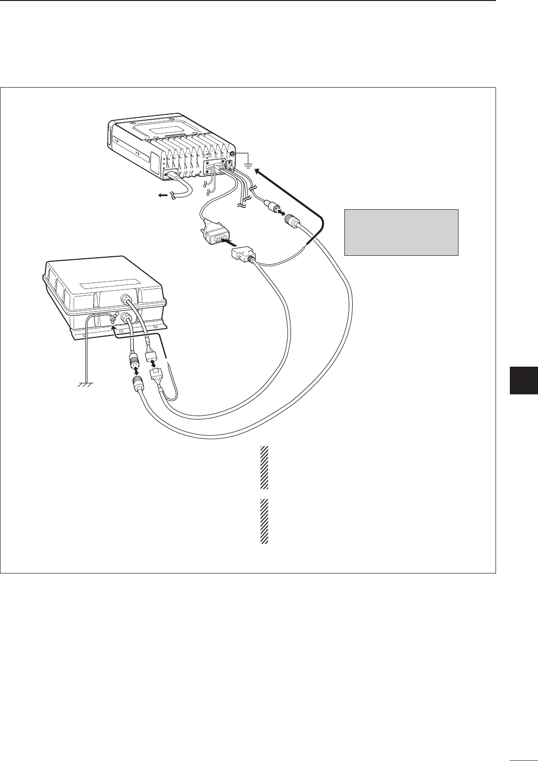
2001 NEW
69
6
CONNECTION AND INSTALLATION
1
2
3
4
5
6
7
8
9
10
11
12
13
14
15
16
17
Quick Reference
AT-140
Ground
IC-F8101 main unit
to a 13.8 V
DC power source
to [ATU]
OPC-2309
(10 m; 32.8 ft): 4 pin
Ground
(see page 51)
D-sub 9 pin
(female)
DO NOT stretch the Ground
wire. This may cause a
ground wire disconnection
and/or damage.
DO NOT pull the antenna and control cable re-
ceptacles. This may cause a cable disconnection
(in the tuner unit), inside connector damage or a
bad connection.
Wrap both the antenna and the control cable con-
nectors with rubber vulcanizing tape, and then
wrap electrical tape over the rubber vulcanizing
tape to help in waterproofing.
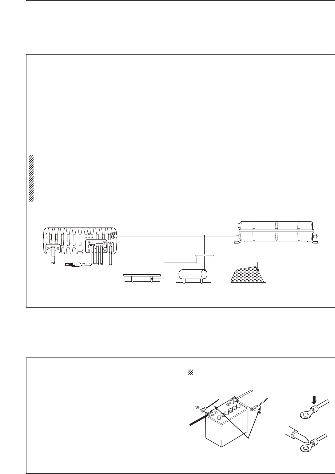
70
6CONNECTION AND INSTALLATION
2001 NEW 2001 NEW
■ Ground connection
The transceiver and antenna tuner MUST have an
adequate RF ground connection. Otherwise, the
overall efficiency of the transceiver and antenna
tuner installation will be reduced. Electrolysis, electri-
cal shocks and interference from other equipment
could also occur.
For best results, use a 50 or 75 mm (2 or 3 inches)
wide copper strap, and make the connection as short
as possible. Ground the transceiver and antenna
tuner to the same ground point, otherwise the volt-
age difference (at the RF level) between two ground
points may cause electrolysis.
RWARNING! When grounding to a metal hull
Use Zinc anodes to protect the hull from electroly-
sis.
Ask your dealer, technical installer or refer to a
technical book, and so on, for RF grounding de-
tails.
Ground system example
Best ground points
• External ground plate
• Copper screen
• Copper foil
Unusable ground points
( These connections may cause an explosion or electrical
shock)
• Gas or electrical pipe
• Fuel tank or oil-catch pan
Copper pipe Metal object Copper screen
■ Power source
The transceiver requires regulated DC power of 13.8
V and at least 28 A. There are two ways to supply
power:
• Direct connection to a 12 V battery in your vehicle
through the supplied DC power cable.
• Use a DC power supply connected to an AC outlet.
DC power cable connection
NOTE: Use terminals for the cable connection.
12 V
battery Supplied
DC power cable
+ red
_ black Crimp
Solder
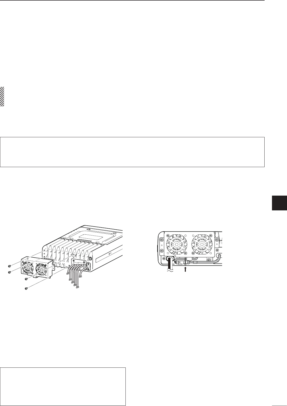
2001 NEW
71
6
CONNECTION AND INSTALLATION
6
■ Antenna
Most stations operate with a whip or long wire (insu-
lated back stay) antenna. However, these antennas
cannot be connected directly to the transceiver since
their impedance may not match with the transceiver
antenna connector.
RDANGER HIGH VOLTAGE!
NEVER touch the antenna element/wire while tun-
ing or transmitting.
q Attach the Cooling fan to the transceiver’s heat-
sink, and tighten the 4 supplied M3 × 8 mm screws.
w Secure the connector and cables using the sup-
plied cable tie.
D AT-140 a u t o m a t i c a n t e n n a t u n e r
See page 69.
D Non-Icom tuner
Some non-Icom tuners may be used with the IC-
F8101. Please consult your dealer if you wish to use
one.
■ CFU-F8100 (Optional Cooling Fan)
For Users in California (U.S.A.)
This CR-1632 Lithium Battery contains Perchlorate
Material—special handling may apply.
See http://www.dtsc.ca.gov/hazardouswaste/perchlorate
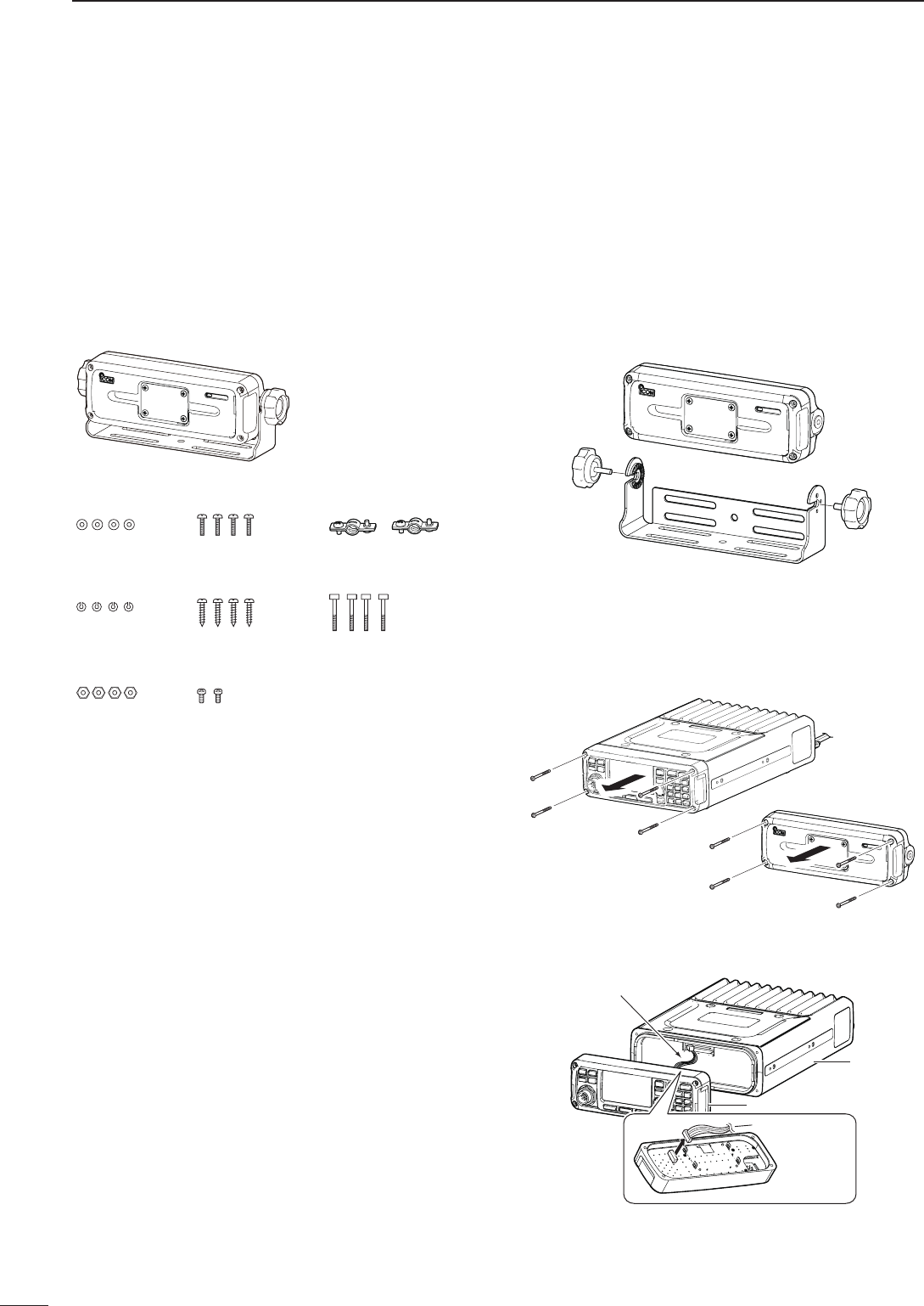
72
6CONNECTION AND INSTALLATION
2001 NEW 2001 NEW
The RMK-6 allows you to install the IC-F8101’s Front
panel separately from the Main unit for added installa-
tion convenience and operation. Use either the optional
OPC-607, OPC-608, OPC-609 or OPC726
s e pa r at i o n
c a b l e
with the RMK-6.
The RMK-6 is the same as the one supplied in the
Separated type transceiver.
D Supplied Accessories
Flat washers
(M5)
RMK-6 with Mounting
bracket
Spring washers
(M5)
Mounting screws
(M5 × 12 mm) Cable clamps
(Screws M2.6 × 5 mm)
Self-tapping screws
(M5 × 16 mm)
Screws
(M3 × 8 mm)
Hex socket screws
Nuts
(M5)
D Separation
The optional OPC-607 (3 m; 9.8 ft), OPC-608 (8 m;
26.2 ft), OPC-609 (1.9 m; 6.2 ft) or OPC-726 (5 m;
16.4 ft) s e pa r at i o n c a b l e is required for separately in-
stalling the transceiver Front panel and Main unit.
q First, make sure the transceiver’s power is OFF,
then disconnect the DC power cable.
w Remove the knob bolts and mounting bracket from
the RMK-6.
e Unscrew the 4 hex socket screws using an allen
wrench, then remove the Front panel from the trans-
ceiver in the direction of the arrow.
• Separate the RMK-6’s Front panel attachment and Main
unit attachment in the same way.
RMK-6
Transceiver
r Disconnect the connection cable from the Front
panel.
Front panel
Connection cable
Connection cable
Main unit
Front panel
■ RMK-6 (Optional Separation kit)
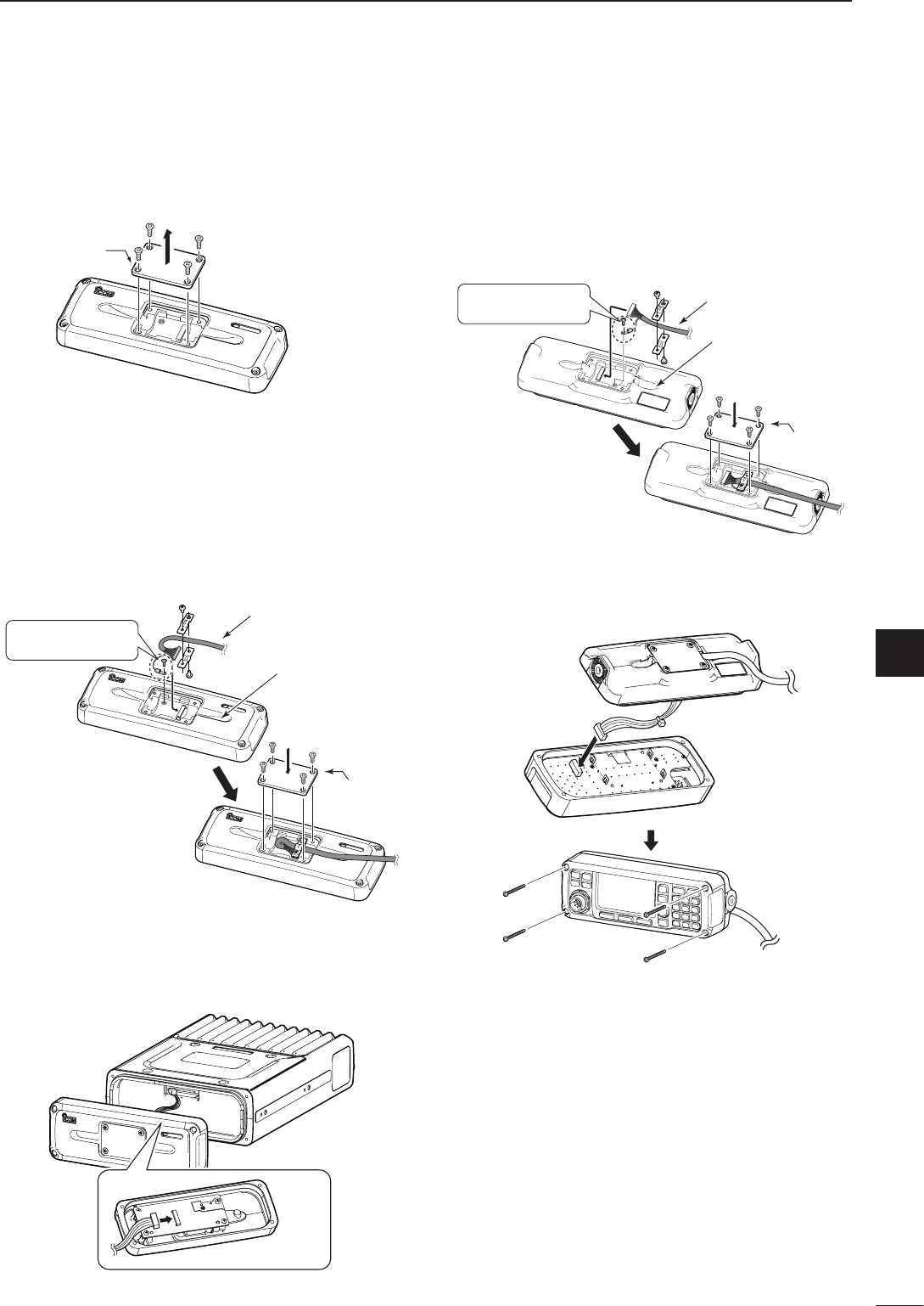
2001 NEW
73
6
CONNECTION AND INSTALLATION
1
2
3
4
5
6
7
8
9
10
11
12
13
14
15
16
17
Quick Reference
t Unscrew the 4 rear plate screws, then remove the
rear plates from both the front panel and Main unit
attachments.
Rear plate *This illustration
shows the descrip-
tion for the Main
unit attachment.
Main unit attachment
y Connect either the OPC-607, OPC-608, OPC-609
or OPC-726 separation cable to the Main unit at-
tachment, as shown below.
After the connecting the cable, replace the rear
plate and the 4 screws.
• The separation cable can be inserted into either the left or
right grooves on the back of the attachment.
Use the supplied
screw (M3 × 8 mm).
Rear plate
Main unit attachment
Cable groove
Separation cable
u Connect the connection cable coming from the
RMK-6, as shown below.
Then tighten the 4 hex socket screws.
i Connect the other end of the Separation cable to
the front panel attachment, as shown below.
After the cable connection, replace the removed
rear plate and the 4 screws.
• The separation cable can be inserted into either the left or
right grooves on the back of the attachment.
Rear plate
Front panel attachment
Cable groove
Separation cable
Use the supplied
screw (M3 × 8 mm).
o Connect the connection cable coming from the
RMK-6, as shown below.
Then tighten the 4 hex socket screws.
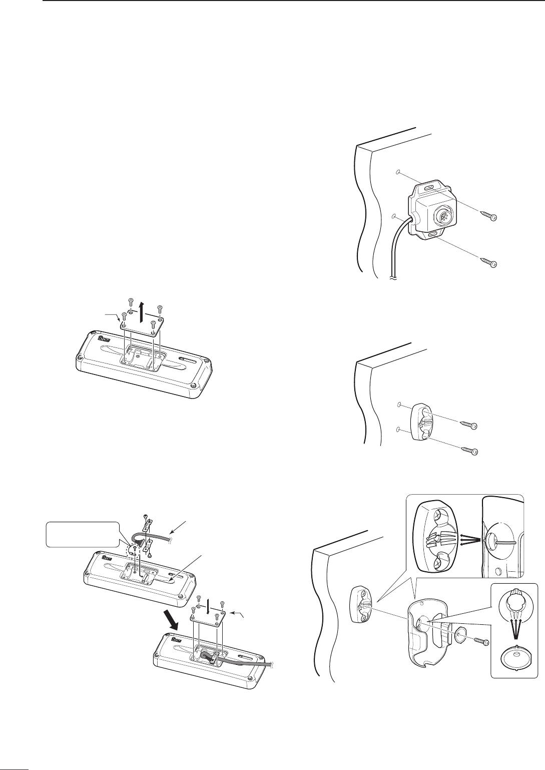
74
6CONNECTION AND INSTALLATION
2001 NEW 2001 NEW
The HM-192 allows you to remotely control the trans-
ceiver by using the microphone instead of the Front
panel*. Use either the optional OPC-607, OPC-608,
OPC-609 or OPC-726
s e pa r at i o n
c a b l e
.
The HM-192 is the same as the one supplied in the
Remote control microphone type transceiver.
* When the HM-192 is connected, the Front panel can not
be used.
D Mounting
The optional OPC-607 (3 m; 9.8 ft), OPC-608 (8 m;
26.2 ft), OPC-609 (1.9 m; 6.2 ft) or OPC-726 (5 m; 16.4
ft) s e pa r at i o n c a b l e is required to install the transceiv-
er’s Main unit and Remote control microphone.
q Unscrew the 4 rear plate screws, then remove the
rear plates from both the Extension MIC connector
and the Main unit attachment.
Rear plate *This illustration
shows the descrip-
tion for the Main
unit attachment.
Main unit attachment
w Connect either the OPC-607, OPC-608, OPC-609
or OPC-726 separation cable to the Main unit at-
tachment, as shown below.
After connecting the cable, replace the rear plate
and the 4 screws.
• The separation cable can be inserted into either the left or
right grooves on the back of the attachment.
Rear plate
Main unit attachment
Cable groove
Separation cable
Use the supplied
M3 × 8 screw.
e
Connect the other side of the Separation cable to the
Extension MIC connector, as described in step w.
After the cable is connected, replace the rear plate
and the 4 screws.
r Attach the Extension MIC connector to the desired
place, then tighten the 2 supplied screws (M4 × 20
mm).
t Attach the holder base to the desired place near the
Extension MIC connector, then tighten the 2 sup-
plied screws (M4 × 20 mm).
y Adjust the MIC holder angle, then tighten the one
supplied M4 × 14 mm screw.
u Connect the HM-192 to the Extension MIC connec-
tor.
■ HM-192 (Optional Remote control microphone)
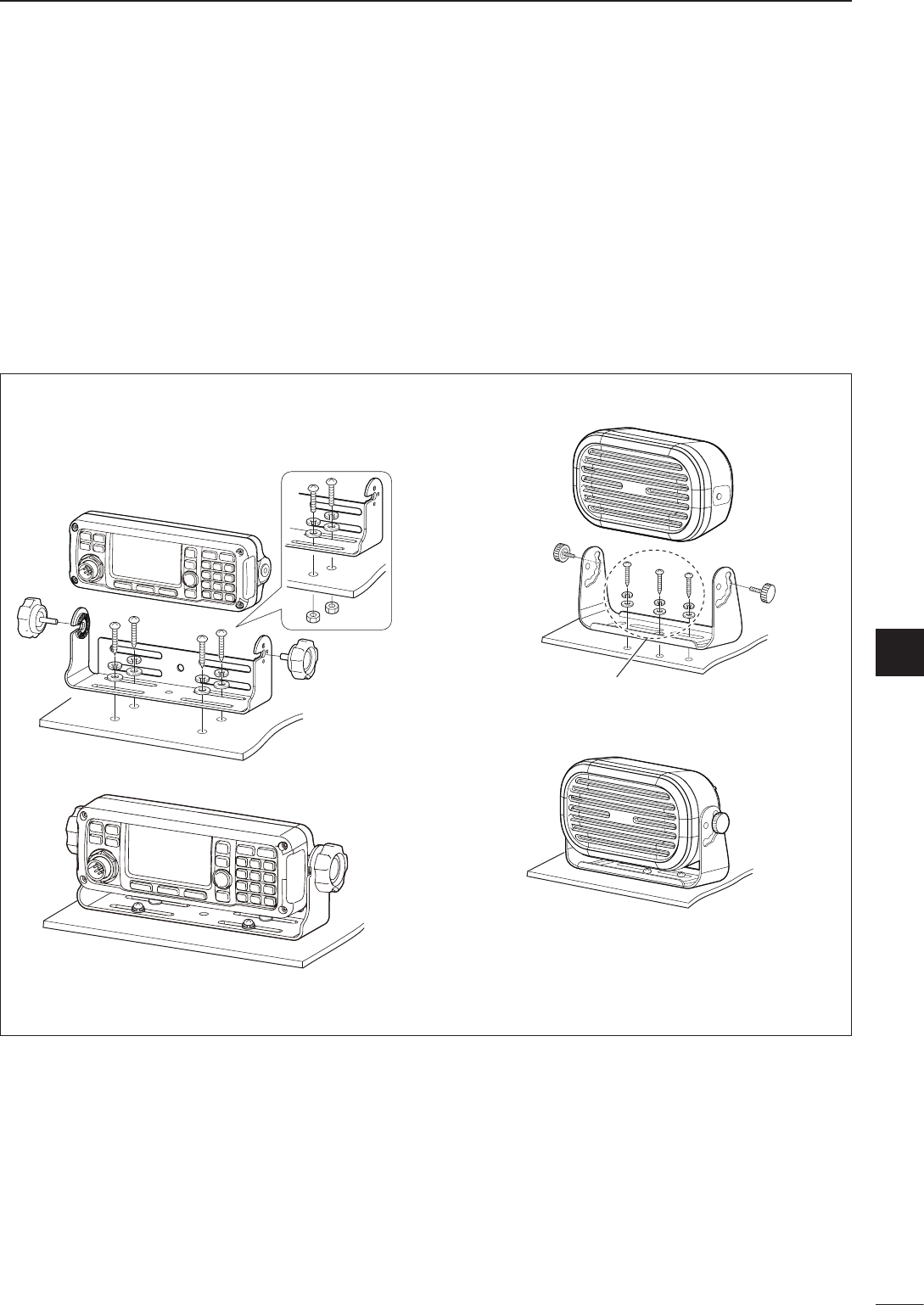
2001 NEW
75
6
CONNECTION AND INSTALLATION
6
■ Mounting
D Mounting location
Select a location that can support the weight of the
transceiver and does not interfere with driving.
NEVER place the main unit or remote controller
where normal operation of the vehicle may be hin-
dered, or where it could cause bodily injury.
NEVER place the main unit or remote controller
where air bag deployment may be obstructed.
DO NOT place the main unit or remote controller
where hot or cold air blows directly onto it.
DO NOT place the main unit or remote controller in
direct sunlight.
D Mounting the controller or speaker
Check the installation angle; the display may not be
easy to read at some angles.
These screws are shown as
mounting examples only.
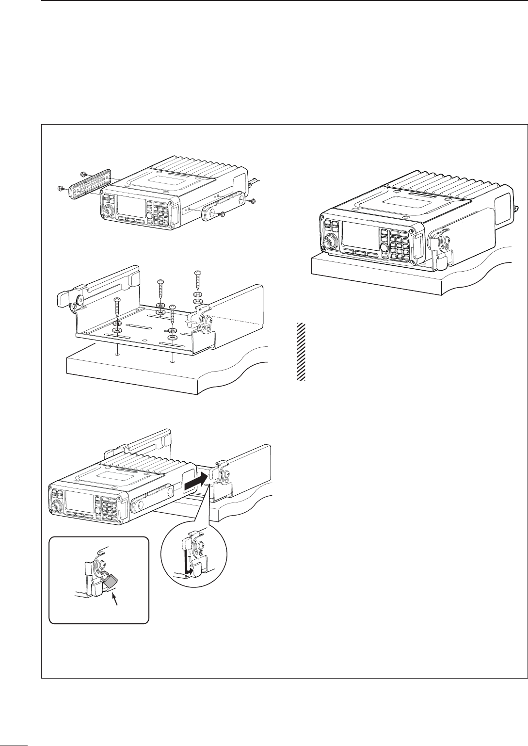
76
6CONNECTION AND INSTALLATION
2001 NEW 2001 NEW
q Attach the mounting plates, and tighten the 2 sup-
plied M5 × 8 mm screws on each side.
w Put the mounting bracket on the board, and then
tighten the 4 supplied screws (M5 × 20 mm).
e Attach the Main unit to the mounting bracket, as
shown below.
Not supplied by Icom
r The completed mounting should look like this.
•Mountingontheboard
RWARNING! Mount the mounting bracket with
4 supplied screws to a surface that is more than
40 mm (1.6 inches) thick and can support more
than 10 kg. The unit must be mounted on only a
flat hard surface.
D Mounting the transceiver
A supplied mounting bracket is used to mount the
transceiver or transceiver’s Main unit onto a flat sur-
face.
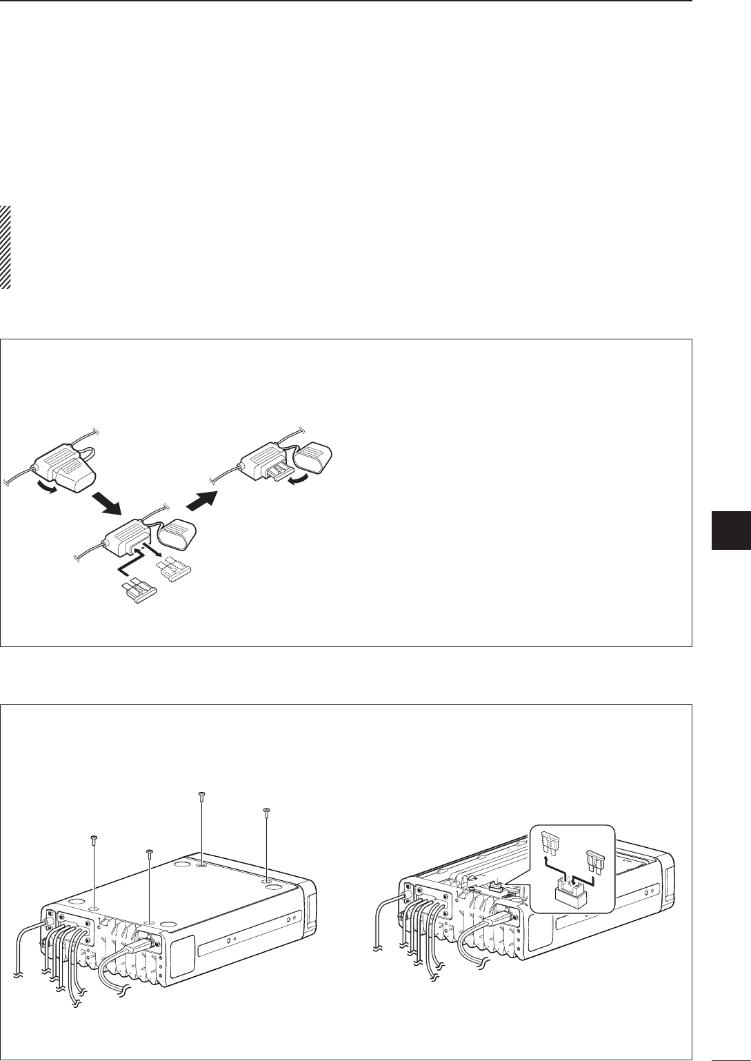
77
6
CONNECTION AND INSTALLATION
2001 NEW
6
■ Fuse replacement
If a fuse blows, or the transceiver stops functioning,
find the source of the problem, and repair it. Then re-
place the damaged fuse with a new, adequately rated
fuse.
RWARNING! Turn OFF the power and discon-
nect the DC power cable from the transceiver before
performing any work on the transceiver. Otherwise,
there is a danger of electric shock, equipment dam-
age and/or fire or injury.
The IC-F8101 has two fuse types installed for trans-
ceiver protection.
• DC power cable ........................................ ATC 30 A
• Circuitry fuse .............................................. ATC 5 A
D Internal fuse replacement
q Turn the transceiver upside down.
w Unscrew 4 screws from the bottom cover, then re-
move the cover.
e Replace the circuitry fuse as shown in the diagram
below.
• Use the supplied ATC 5 A fuse.
r Reattach the bottom cover to its original position.
D DC power cable fuse replacement
Refer to the figure below for the DC power cable fuse
replacement.
ATC 30 A fuse
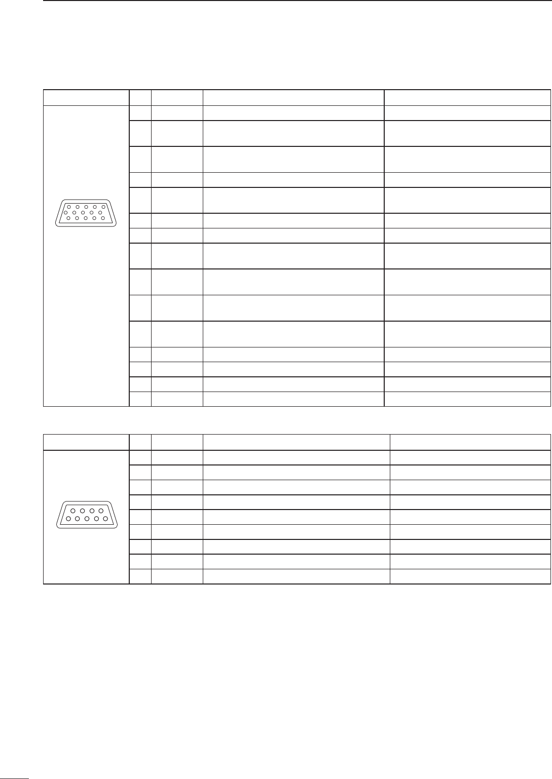
78
6CONNECTION AND INSTALLATION
2001 NEW
■Connector information
ATU Pin Pin name Description Specification
15
69
1 KEY Key signal input. —
2 START Start/bypass signal output. —
3 13.8V 13.8 V output for Antenna tuner. 13.8 V, maximum 2 A
4 13.8V 13.8 V output for Antenna tuner. 13.8 V, maximum 2 A
5 GND Connect to ground. —
6 GND Connect to ground. —
7 NC — —
8 NC — —
9 NC — —
ACC Pin Pin name Description Specification
1 CI-V — —
2 AF IN Input terminal for the AF signal. Input sensitivity (Data mode):
More than 52.5 W at 100 mV
3 AF OUT Output terminal for the AF signal. Output level: 200 to 400 mVrms
when receiving Data mode
4 AF GND Ground line for the AF signal. —
5 GPS RXD Input terminal for receive data from GPS
unit. NMEA0183
6 NC — —
7 RELAY Goes to ground when transmitting. Less than 100 mV
8 EALC ALC voltage input. Control sensitivity (at –3 V input):
More than 40 dB suppression
9 MODPTT PTT input terminal.
When grounded, transmits. Input voltage: Less than 0.8 V
for transmit
10 CW KEY CW and FSK keying input. CW: Less than 0.6 V for transmit
RTTY: Open=Mark
11 EALARM Output terminal for the Alarm signal. Output current: 12 mA±10%
Open collector
12 GND Connect to ground. —
13 NC — —
14 NC — —
15 NC — —
11 15
1
6
5
10
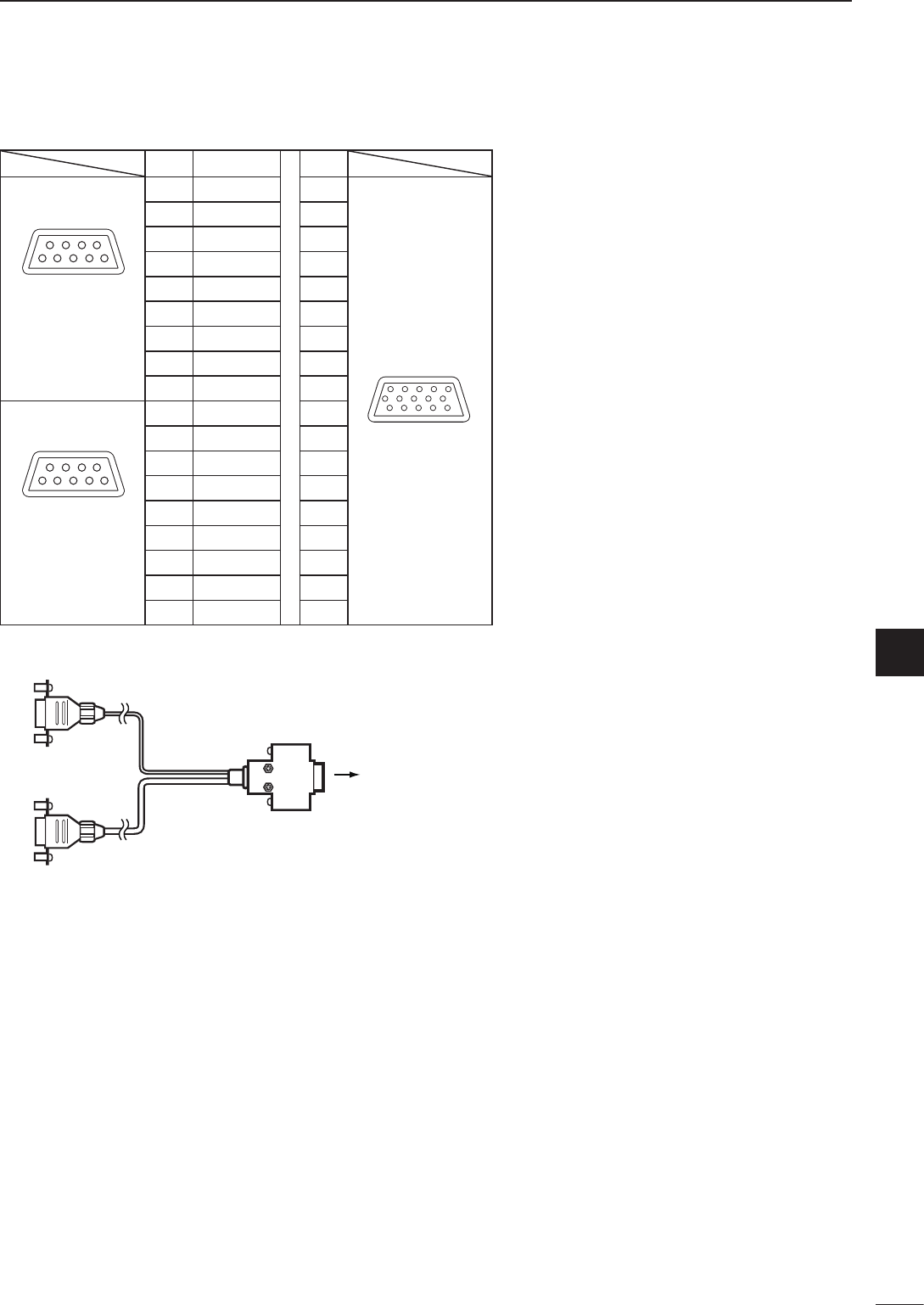
79
6
CONNECTION AND INSTALLATION
1
2
3
4
5
6
7
8
9
10
11
12
13
14
15
16
17
Quick Reference
Pin Pin name Pin
15
69
1 NC —
2 GPS RX 5
3 NC —
4 NC —
5 GND 12
6 NC —
D-sub 9 pin
(Male)
7 NC —
11 15
1
6
5
10
8 NC —
9 NC —
15
69
1 CI-V 1
2 MODPTT 9
3 NC —
4 NC —
5 NC —
6 AF OUT 3
D-sub 9 pin
(Female)
7 AF IN 2 D-sub 15 pin
(Male)
8 AF GND 4
9 GND 12
■Connector information for OPC-2308
to IC-F8101 [ACC]
OPC-2308
D-sub 9 pin
(male)
D-sub 15 pin
(male)
D-sub 9 pin
(female)

7
80
SPECIFICATIONS
2001 NEW
D General
• Frequency coverage:
Receive 0.5–29.9999 MHz
Transmit 1.6–29.9999 MHz
• Mode:
AUS versions
J3E (USB), A3E (AM) RX only
Other versions J3E (USB/LSB), A3E (AM)
A1A (CW), F1B (FSK),
J2B (D1, D2, D3)
• No. of memory Ch.: 500 channels (maximum)
• Usable temp. range: –30˚C to +60˚C;
–22°F to +140°F
• Frequency stability: ±0.3 ppm (–30˚C to +60˚C;
–22°F to +140°F)
• Antenna impedance: 50 Ω
• Power supply: 13.8 V DC (negative ground)
AUS versions 10.8–15.6 V DC
Other versions 11.73–15.87 V DC
• Current drain:
Transmit Less than 28 A
(at maximum power)
Receive Less than 3.0 A
(at maximum audio)
• Dimensions (projections are not included):
Main/Front package
62(H)×174(W)×259(D) mm
2.4(H)×6.9(W)×10.2(D) in
• Weight (approximately):
Main/Front package
3.9 kg, 8.6 lb
D Transmitter
• Output power (typical):
AUS versions
J3E HIGH 100 W p-p
MID 50 W p-p
LOW 10 W p-p
Other versions
J3E/A1A HIGH 125 W p-p
MID 50 W p-p
LOW 10 W p-p
A3E HIGH 30 W Carrier
MID 12.5 W Carrier
LOW 3 W Carrier
F1B/J2B HIGH 75 W p-p
MID 50 W p-p
LOW 10 W p-p
• Spurious emission:
USA versions 64 dB
below peak output power
Other versions 64 dB (typical)
below peak output power
• Carrier suppression: 50 dB
below peak output power
• Unwanted sideband suppression:
400 Hz 55 dB
below peak output power
1 kHz 65 dB
below peak output power
• Duty cycle:
Normal conversation 100% ( –30˚C to +60˚C;
–22°F to +140°F)
Continuous Data mode
25% ( –30˚C to +30˚C;
–22°F to +86°F)
All mode with Fan (CFU-F8100) is active
100% ( –30˚C to +45˚C;
–22°F to +113°F)
D Receiver
• Sensitivity:
J3E (Pre Amp ON)
(0.5–1.5999 MHz) 14 dBµV (10 dB S/N)
(1.6–29.9999 MHz) –14 dBµV (10 dB S/N)
A3E
(0.5–1.5999 MHz) 22 dBµV (10 dB S/N)
(1.6–29.9999 MHz) 6 dBµV (10 dB S/N)
• Spurious response rejection ratio:
More than 70 dB
• AF output power (at 13.8 V DC):
More than 4.0 W at 10%
distortion with a 4 Ω load
•
Clarifier range
: ±200 Hz
All stated specifications are typical and subject to change without notice or obligation.
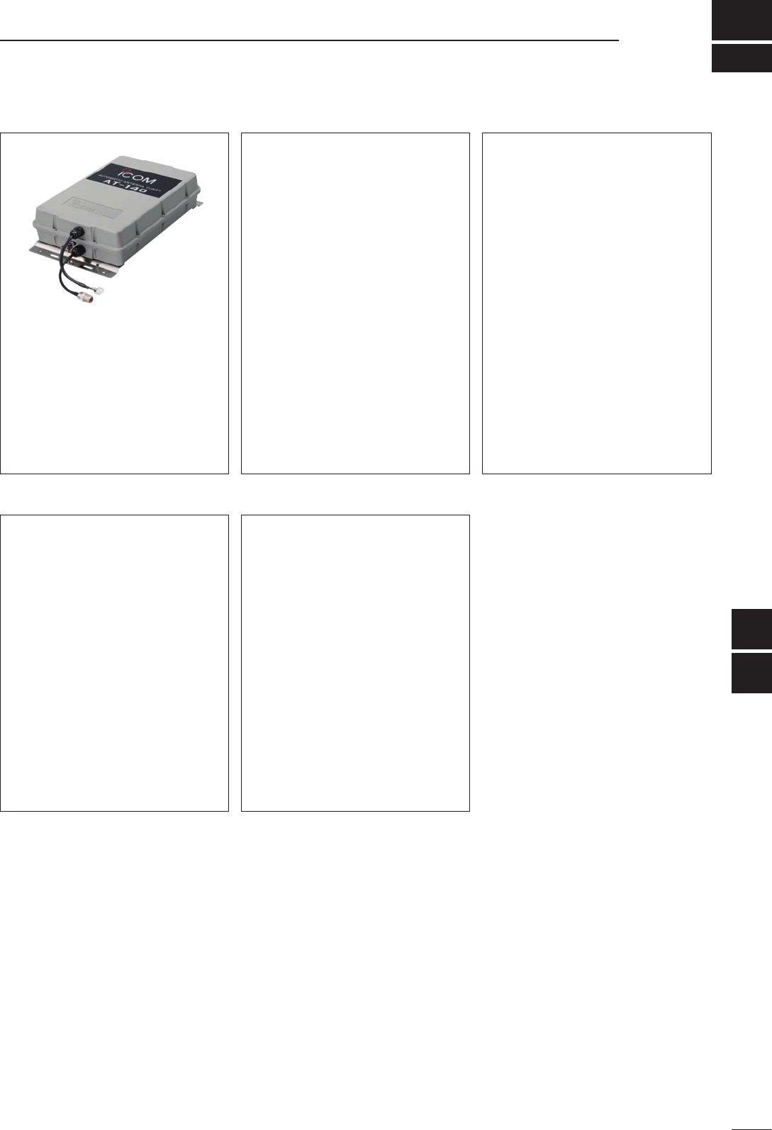
8
81
OPTIONS
1
2
3
4
5
6
7
8
9
10
11
12
13
14
15
16
17
Quick Reference
AT-140 a u t o m a t i c a n t e n n a t u n e r
Antenna and control cable receptacles
for easy installation, and a tuner bypass
function is available.
AH-740, AH-760
a u t o m a t i c t u n i n g a n t e n n a
A tuner bypass function is available.
These antennas will be available in the
near feature.
OPC-2308 s h i e l d e d c o n t r o l c a b l e
The shielded control cable protects the
transceiver from RF feedback and con-
nects a GPS unit or a modem unit to the
transceiver.
OPC-2309 s h i e l d e d c o n t r o l c a b l e
The shielded control cable protects the
transceiver from RF feedback and ex-
tends the separation between the AT-140
and the transceiver up to 10 meters (32.8
feet).
CFU-F8100 c o o l i n g f a n
MB-126 m o u n t i n g b r a c k e t
RMK-6 s e pa r at i o n k i t
The same as that supplied with the IC-
F8101 Separated Type.
Allows you to install the transceiver front
panel separate from the Main unit for op-
erating convenience. The RMK-6 requires
either the OPC-607, OPC-608, OPC-609
or OPC-726 separation cable.
OPC-607/OPC-608/OPC-609/OPC-726
s e pa r at i o n c a b l e
OPC-607: 3 m (9.8 ft)
OPC-608: 8 m (26.2 ft)
OPC-609: 1.9 m (6.2 ft)
OPC-726: 5 m (16.4 ft)
SP-10, SP-25, SP-30, SP-35/35L
e x t e r n a l s p e a k e r s
A mounting bracket is supplied with the
speaker.
Impedance: 4 Ω
Max. AF input: 5 W (SP-10)
7 W (SP-25, SP-35/35L)
30 W (SP-30)
HM-192 #12
r e m o t e c o n t r o l m i c r o p h o n e
The same as that supplied with the IC-
F8101 Remote control microphone type.
Allows you to remotely control the trans-
ceiver with the microphone. The HM-192
requires either the OPC-607, OPC-608,
OPC-609 or OPC-726 separation cable.
HM-193 h a n d m i c r o p h o n e
The same as that supplied with the IC-
F8101 One package type or Separated
Type.

1-1-32 Kamiminami, Hirano-ku, Osaka 547-0003, Japan
2001 NEW
A-7077H-1EX-0a
Printed in Japan
© 2013 Icom Inc.
Printed on recycled paper with soy ink.