ICOM orporated 353801 UHF Transceiver User Manual IC F3000 F4000 Series Instruction Manual
ICOM Incorporated UHF Transceiver IC F3000 F4000 Series Instruction Manual
UserManual.wiki
>
ICOM orporated
>
353801 User Manual
User Manual
Navigation menu
Upload a User Manual
Namespaces
Wiki Guide
HTML
PDF
Info
Views
User Manual
Discussion / Help
Navigation
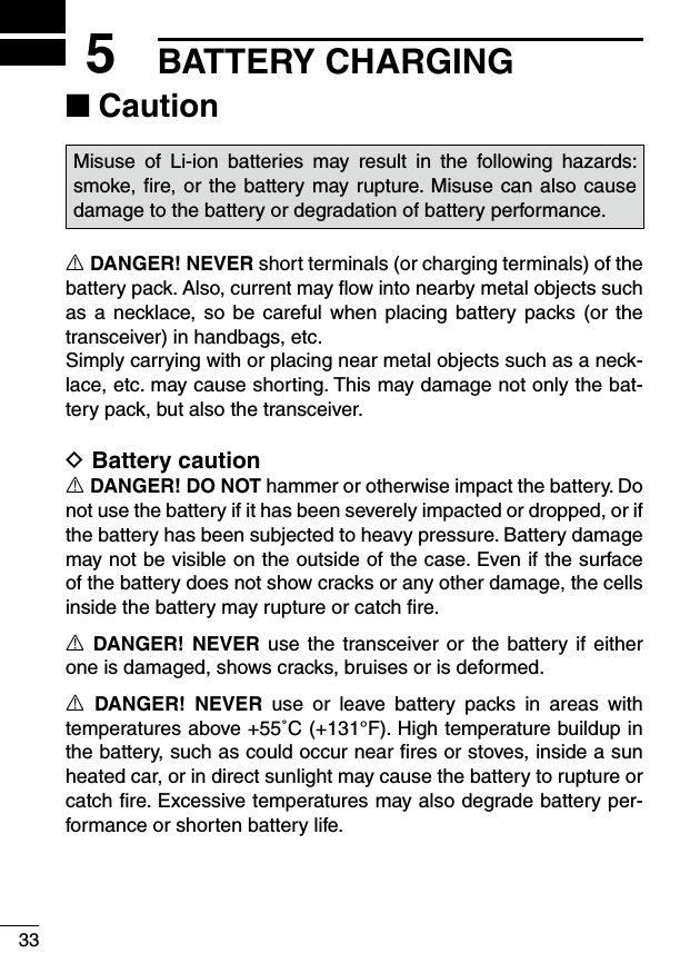
![ivDO NOT push [PTT] when you do not actually intend to transmit.DO NOT use or place the transceiver in direct sunlight or in areas with temperatures below–20°C (–4°F) or above +55°C (+131°F).DO NOT modify the transceiver. The specifications may change and then not comply with the requirements of a corresponded regulation. The transceiver warranty does not cover any problems caused by unauthorized modification.DO NOT use harsh solvents such as benzine or alcohol when cleaning, as they will damage the transceiver surfaces.BE CAREFUL! The transceiver will become hot when operating it continuously for long periods of time.BE CAREFUL! The transceiver meets IP67 requirements for dust-tight and waterproof protection.However, once the transceiver has been dropped, dust-tight and waterproof protection cannot be guaranteed because of possible damage to the transceiver’s case or the waterproof seal.Even when the transceiver power is OFF, a slight current still flows in the circuits. Remove the battery pack or batteries from the trans-ceiver when not using it for a long time. Otherwise, the installed battery pack or batteries will become exhausted, and will need to be recharged or replaced.MAKE SURE to turn the transceiver power OFF before connect-ing the supplied/optional equipment.](https://usermanual.wiki/ICOM-orporated/353801/User-Guide-2202768-Page-5.png)
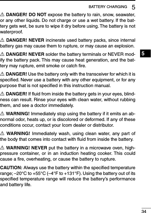
![52PANEL DESCRIPTIONFront, top and side panels ■MicrophoneSpeakerrweqyLOWER KEYuUPPER KEYtPTT SWITCHiANTENNACONNECTORROTARYSELECTORLED INDICATORVOLUMECONTROLMULTI CONNECTORq ROTARY SELECTOR Rotate to select the preprogrammed memory channels or scan lists, depending on the preprogramming.w VOLUME CONTROL [VOL] Rotate to turn the power ON or OFF, and adjust the audio level.](https://usermanual.wiki/ICOM-orporated/353801/User-Guide-2202768-Page-12.png)
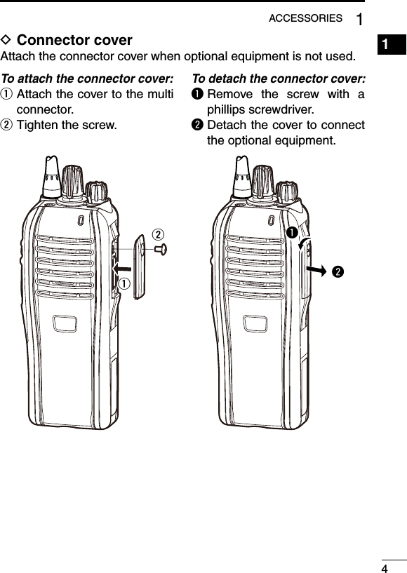
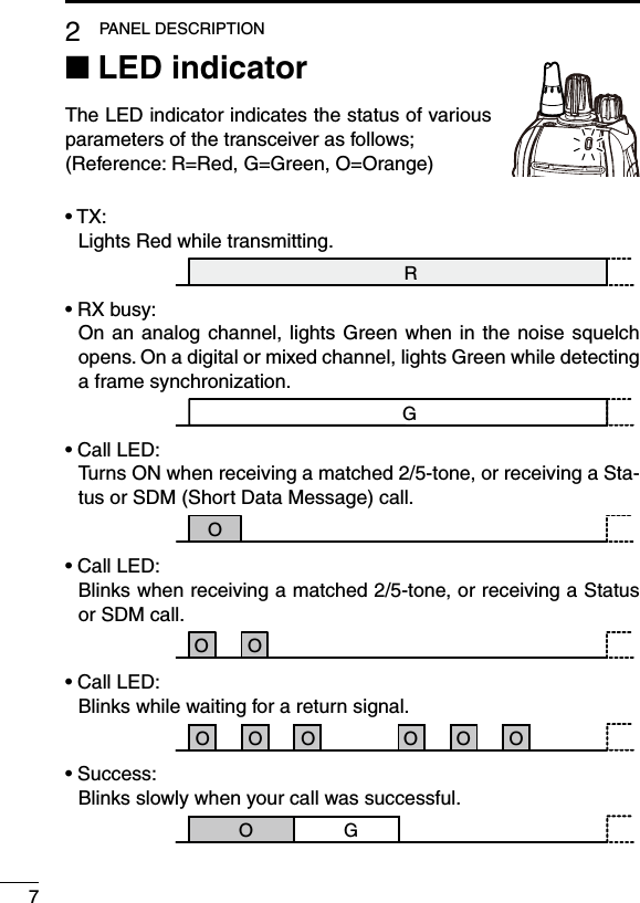
![62PANEL DESCRIPTIONe LED INDICATOR (pp. 7–9)Lights red while transmitting. ➥ Lights green while receiving a signal, or when the squelch ➥is open. Lights/blinks orange when the matched 2/5-tone code is re- ➥ceived, depending on the presetting.r MULTI CONNECTOR Connect optional equipment.t PTT SWITCH [PTT]Hold down to transmit; release to receive.y LOWER KEY [Lower]u UPPER KEY [Upper] A desired function can be assigned by your dealer. (p. 10)i ANTENNA CONNECTOR Connect the antenna.1234567891011121314151617181920Connector coverNOTE: Attach the cover when optional equipment is not used. (p. 4)](https://usermanual.wiki/ICOM-orporated/353801/User-Guide-2202768-Page-13.png)
![102PANEL DESCRIPTION1234567891011121314151617181920Programmable function keys ■The following functions can be assigned to the [Upper] and [Lower] programmable function keys.Consult your Icom dealer or system operator for details concerning your transceiver’s programming.SCANPush to start and cancel scanning.•WhenthescanstartedwiththePowerONScanorAutoScanfunc-tion, push to pause the scan. The paused scan resumes after the specified time period has passed.PRIORITY A CHANNEL, PRIORITY B CHANNELPush to select the Priority A or Priority B channel.PRIORITY A CHANNEL (REWRITE),PRIORITY B CHANNEL (REWRITE)Push to select the Priority A or Priority B channel. ➥ Hold down [Prio A (Rewrite)] or [Prio B (Rewrite)] for 1 second ➥to assign the operating channel to the Priority A or Priority B channel, respectively.MEMORY CHANNELS 1, 2, 3, 4Push to directly select memory channel 1, 2, 3 or 4, if programmed. Consult your dealer for details.LONE WORKER (p. 25)Hold down for 1 second to turn ON the Lone Worker function. ➥ •WhentheLoneWorkerfunctionisturnedON,andnooperationisperformed for the specified time period, the Emergency function is automatically turned ON.Push to turn OFF the Lone Worker function. ➥](https://usermanual.wiki/ICOM-orporated/353801/User-Guide-2202768-Page-17.png)
![112PANEL DESCRIPTIONProgrammed function keys (Continued) ■MONITOR, MONITOR (AUDIBLE) Push to turn the CTCSS (DTCS) or 2/5-tone squelch Mute ON ➥or OFF. •OnlyduringLMRoperation,push to openanysquelch func-tions, or deactivate any mute functions. •OnlyduringPMRoperation,pushtoactivateoneortwoofthefollowing functions* on each channel. - Hold down to unmute the channel (Audible mode). - Push to mute the channel (Inaudible mode). - Push to send a ‘reset code’ after the communication is finished. *Ask your dealer for details. NOTE: The unmute condition may automatically return to the mute condition, after a specified time period. ➥Depending on the presetting, holding down this key for 1 second cancels a scan.LOCKHold down to electronically lock all programmable keys except [Moni(Audi)], [Call] (including Call A and Call B), [Emergency], Sur-veillance] and [Lone Worker].HIGH/LOW (p. 24)Select the transmit output power level temporarily or permanently, depending on the presetting.•Askyourdealerfortheoutputpowerlevelforeachselection.TALK AROUNDHold down for 1 second to turn ON the Talk Around function. ➥ •TheTalkAroundfunctionequalizesthetransmitfrequencytothereceive frequency for transceiver-to-transceiver communication.Push to turn OFF the Talk Around function. ➥DTMF AUTODIALPush to transmit a programmed DTMF code.](https://usermanual.wiki/ICOM-orporated/353801/User-Guide-2202768-Page-18.png)
![122PANEL DESCRIPTIONRE-DIALPush to transmit the last-transmitted DTMF code.NOTE: TX memories are cleared after turning OFF the transceiver.WIDE/NARROWPush to toggle the IF bandwidth between Wide, Mid* or Narrow.* Depending on the presetting, the Mid channel width may not be selectable. Ask your dealer for details.CALL, CALL A, CALL BPush to transmit a 2/5-tone code.•Tonecalltransmissionmaybenecessarybeforeyoucallanothersta-tion, depending on your signalling system.•[Call A] and/or [Call B] keys may be selectable when your systememploys selective ‘Individual/Group’ calls. Ask your dealer which call is assigned to each key.EMERGENCYHold down for specified time period to transmit an emergency call.•Theemergencycalltransmitswithbeeps,andtheLEDlightsred.•The transceiver can transmit an emergency call without the beepsounding and the LED indicator lighting. Ask your dealer for details.•If you want to cancel the emergency call, hold down the key againbefore transmitting the call.•Theemergencycallistransmittedonetimeonly,orrepeatedlyuntilre-ceiving an acknowledgement signal, or until the power is turned OFF. When a matched 5-tone code signal is received, the emergency func-tion can be cancelled, depending on the presetting. (PMR operation only)SURVEILLANCEHold down for 1 second to turn ON the Surveillance function. ➥ •WhenthisfunctionisturnedON,thebeepisnotheardandtheLEDdoes not light when a signal is received, or a key is pushed.Push to turn OFF the Surveillance function. ➥1234567891011121314151617181920](https://usermanual.wiki/ICOM-orporated/353801/User-Guide-2202768-Page-19.png)
![Programmed function keys (Continued) ■SIRENHold down for 1 second to emit a siren sound.This function can be used for situations other than an emergency alert, such as a security alarm for example.The transceiver emits the siren sound until the power is turned OFF.SCRAMBLER Hold down for 1 second to turn ON the Voice Scrambler function ➥while operating in the digital mode.Push to turn OFF the Voice Scrambler function. ➥ANNOUNCEPush to turn the Channel Announce function ON or OFF.•WhenthisfunctionisturnedON,thetransceiverannouncestheposi-tion of [ROTARY SELECTOR] between 1 and 16 when rotating [RO-TARY SELECTOR] to a desired number.132PANEL DESCRIPTION](https://usermanual.wiki/ICOM-orporated/353801/User-Guide-2202768-Page-20.png)
![143BASIC OPERATION1234567891011121314151617181920Turning ON the power ■Prior to using the transceiver for the first time, the battery pack must be fully charged for optimum life and operation. (p. 33)Rotate [VOL] to turn ON the power. ➥[VOL]](https://usermanual.wiki/ICOM-orporated/353801/User-Guide-2202768-Page-21.png)
![Channel selection ■Several types of channel selections are available. Methods may dif-fer, depending on the presetting.To select a desired operating channel, do one of the following.•Rotate[ROTARYSELECTOR].•Pushoneofthememorychannelkeys,[MR-CH1]to[MR-CH4].•Push[PrioA],[PrioB],[PrioA(Rewrite)]or[PrioB(Rewrite)].AUTOMATIC SCAN TYPE:Selecting a channel is not necessary. When turning ON the power, the transceiver automatically starts scanning. Scanning stops when a signal is detected.Voting Operation DThe transceiver automatically starts scanning when a zone, speci-fied for the voting operation, is selected.The voting scan detects the signal of the repeater and automati-cally selects the strongest station.153BASIC OPERATION](https://usermanual.wiki/ICOM-orporated/353801/User-Guide-2202768-Page-22.png)
![163BASIC OPERATION1234567891011121314151617181920Call procedure ■When your system employs tone signalling (excluding CTCSS and DTCS), the tone call procedure may be necessary prior to voice transmission. The tone signalling that is employed in the transceiver may be a selective calling system, which allows you to call only specific station(s), and prevents unwanted stations from contacting you. Select a desired TX code channel or 2/5-tone code, according to qyour System Operator’s instructions. •Thismaynotbenecessary,dependingontheprogramming. Push [Call] (assigned to one of the dealer programmable keys.) w(p. 12) After transmitting a 2/5-tone code, the remainder of your com- emunication can be carried out normally.Selective calling Non-selective calling](https://usermanual.wiki/ICOM-orporated/353801/User-Guide-2202768-Page-23.png)
![173BASIC OPERATIONReceiving and transmitting ■CAUTION: Transmitting without an antenna will damage the transceiver. See page 1 for antenna attachment.Receiving:Rotate [VOL] to turn ON the power. q Rotate [ROTARY SELECTOR], or push one of the memory wchannel keys, [MR-CH 1] to [MR-CH 4], to select a channel. When receiving a call, adjust the audio output to a comfortable elistening level.NOTE: When a matched RX code signal is received, the trans-ceiver automatically transmits its microphone audio for a speci-fied time period, depending on the presetting. Ask your dealer for details.Transmitting:Wait for the channel to become clear to avoid interference. While holding down [PTT], speak into the microphone at a nor- qmal voice level.Release [PTT] to receive. wIMPORTANT: To maximize the readability of your signal;1. Pause briefly after pushing [PTT].2. Hold the microphone 5 to 10 cm (2 to 4 inches) from your mouth, then speak at a normal voice level.](https://usermanual.wiki/ICOM-orporated/353801/User-Guide-2202768-Page-24.png)
![183BASIC OPERATION1234567891011121314151617181920Transmitting notes D•TransmitinhibitfunctionThe transceiver has several inhibit functions, which restrict trans-mission under the following conditions:- The channel is muted. (PMR operation only)- The channel is busy.- A signal with an unmatched (or matched) CTCSS (or DTCS) tone is received.- The selected channel is a ‘receive only’ channel.•Time-outtimerAfter continuously transmitting longer than the preprogrammed time period, the time-out timer activates, and stops further transmitting.•PenaltytimerOnce the time-out timer activates, transmitting is further inhibited for a time period determined by the penalty timer.•PTTIDcallThe transceiver automatically sends the ID code (5-tone, DTMF, BIIS or dPMR operations) when [PTT] is pushed (beginning of the transmission) and/or released (end of transmission), depending on the presetting.](https://usermanual.wiki/ICOM-orporated/353801/User-Guide-2202768-Page-25.png)
![DTMF transmission DIf the transceiver has [DTMF Autodial] assigned to it, the automatic DTMF transmission function is usable.Push [DTMF Autodial] to transmit the DTMF code. ➥Receiving a Stun, Kill and Revive command DThe dispatcher can send a signal that will stun, kill or revive your transceiver.When the Stun command is received, a beep sounds*, and the transceiver becomes unusable. Receiving a Revive command is necessary to operate the transceiver again in this case.When the Kill command is received, a beep sounds*, and the trans-ceiver becomes unusable. Cloning the transceiver is necessary to operate the transceiver again in this case.* Depending on the presetting. Ask your dealer for details.193BASIC OPERATION](https://usermanual.wiki/ICOM-orporated/353801/User-Guide-2202768-Page-26.png)
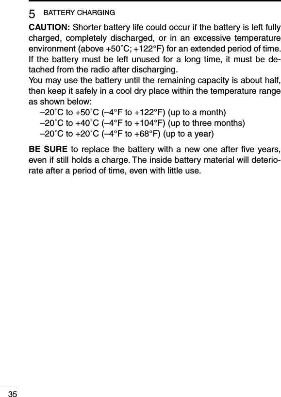
![Setting the microphone gain ■Adjusts the microphone gain. Rotate [VOL] to turn the trans- qceiver power OFF. Set [ROTARY SELECTOR] to wChannel 16. While holding down [Upper], ro- etate [VOL] to turn ON the power and enter the microphone gain adjustment mode. Push [Upper] to increase, or rpush [Lower] to decrease the microphone gain. •Theadjustablerangeis1(mini-mum) to 4 (maximum). •A beep sounds after pushing[Upper] or [Lower]. An error beep sounds if you try to decrease more than 1 or try to increase more than 4. Therefore, you can determine the current level setting by the type of beep that sounds. Rotate [VOL] to turn the power OFF, then ON again to exit the tmicrophone gain adjustment mode.NOTE:This operation may not be available, depending on the preset-ting. Ask your dealer for details.203BASIC OPERATION1234567891011121314151617181920[Upper][VOL][ROTARY SELECTOR][Lower]](https://usermanual.wiki/ICOM-orporated/353801/User-Guide-2202768-Page-27.png)
![Setting the squelch level ■The squelch circuit mutes the received audio signal, depending on the signal strength. Rotate [VOL] to turn OFF the qtransceiver power. Set [ROTARY SELECTOR] to wany channel other than Chan-nel 16. While holding down [Upper], ro- etate [VOL] to turn ON the power and enter the squelch level ad-justment mode. Push [Upper] to increase the rsquelch level (tight squelch), or push [Lower] to decrease the squelch level (loose squelch). •Theadjustablerangeis0(loosesquelch) to 9 (tight squelch). •Abeepsoundsafterpushing[Upper]or[Lower]. An error beep sounds if you try to decrease more than 0 or try to increase more than 9. Therefore, you can determine the current level setting by the type of beep that sounds. Rotate [VOL] to turn the power OFF, then ON again to exit the tsquelch level adjustment mode.NOTE: This operation may not be available, depending on the presetting. Ask your dealer for details.213BASIC OPERATION[Upper][VOL][ROTARY SELECTOR][Lower]](https://usermanual.wiki/ICOM-orporated/353801/User-Guide-2202768-Page-28.png)
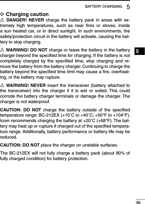
![Setting the Beep level ■The beep function can be turned ON or OFF, and its level can be adjusted between 1 and 5, or 1 (linked) and 5 (linked). When a Linked option is selected, the beep level is adjustable with [VOL]. Rotate [VOL] to turn OFF the qtransceiver power. Set [ROTARY SELECTOR] to wany channel other than Chan-nel 16. While holding down [Lower], ro- etate [VOL] to turn ON the power and enter the beep level adjust-ment mode. Push [Upper] to change the rbeep level, or push [Lower] to turn the beep function ON or OFF. •Theadjustablerangeis1to5or1 (Linked) to 5 (Linked). •A beep sounds after pushing[Upper] or [Lower]. Therefore, you can determine the current level setting by the type of beep that sounds. Rotate [VOL] to turn the power tOFF, then ON again to exit the beep level adjustment mode.NOTE: This operation may not be available, depending on the presetting. Ask your dealer for details.223BASIC OPERATION1234567891011121314151617181920[Upper][VOL][ROTARY SELECTOR][Lower]254315 (Linked)4 (Linked)3 (Linked)2 (Linked)1 (Linked)[Lower]operation[Upper]operation](https://usermanual.wiki/ICOM-orporated/353801/User-Guide-2202768-Page-29.png)
![233BASIC OPERATIONSetting the Ringer level ■The Ringer level can be adjusted between 1 and 5, or 1 (Linked) and 5 (Linked). When a Linked option is selected, the Ringer level is adjustable with [VOL]. Rotate [VOL] to turn OFF the qtransceiver power. Set [ROTARY SELECTOR] to wChannel 16. While holding down [Lower], ro- etate [VOL] to turn ON the power and enter the Ringer level ad-justment mode. Push [Upper] to increase, or rpush [Lower] to decrease the Ringer level. •Theadjustablerangeis1to5or1 (Linked) to 5 (Linked). •A beep sounds after pushing[Upper] or [Lower]. Therefore, you can determine the current level setting by the type of beep that sounds. Rotate [VOL] to turn the power tOFF, then ON again to exit the beep level adjustment mode.NOTE: This operation may not be available, depending on the presetting. Ask your dealer for details.[Upper][VOL][ROTARY SELECTOR][Lower]254315 (Linked)4 (Linked)3 (Linked)2 (Linked)1 (Linked)[Lower]operation[Upper]operation](https://usermanual.wiki/ICOM-orporated/353801/User-Guide-2202768-Page-30.png)
![243BASIC OPERATION1234567891011121314151617181920Output power level selection ■If the transceiver has [High/Low] assigned to it, the transmit output power level can be selected, depending on the presetting.When the battery voltage drops to a low power level and the LED indicator status is “Low Battery 2,” the output power automatically switches to “Low 1.” (pp. 8, 11)Push [High/Low] to select the transmit output power level. ➥ •Onebeepsoundswhen“Low1”isselected. •Twobeepssoundwhen“Low2”isselected. •Threebeepssoundwhen“High”isselected.Priority A channel selection ■When one of the following operations is performed, the transceiver automatically selects the Priority A channel.•TurningthepowerON The Priority A channel is selected each time the transceiver power is turned ON.•AutoresetThe Priority A channel is selected when the Auto Reset timer ends.](https://usermanual.wiki/ICOM-orporated/353801/User-Guide-2202768-Page-31.png)
![253BASIC OPERATIONLone Worker Emergency Call ■When the Lone Worker function is turned ON, and no operation is performed for the specified time period*, the transceiver enters the emergency mode, and then the countdown for the emergency call transmission starts.After the specified time period* has passed, an emergency call is automatically transmitted once, or repeatedly*.If someone operates the transceiver before the call is transmitted, the transceiver exits the emergency mode, and the emergency call is can-celled.* Depending on the presetting. Ask your dealer for details. Hold down [Lone Worker] for 1 second to turn ON the Lone qWorker function. w Push [Lone Worker] to turn OFF the Lone Worker function.Man Down Emergency Call ■When the transceiver has been left in a horizontal position for the preprogrammed time period, the transceiver enters the emergency mode, and then the countdown for the emergency call transmission starts.After the preprogrammed time period, an emergency call is auto-matically transmitted once, or repeatedly, depending on the pre-programmed settings.If the transceiver is placed in a vertical position before the first transmission, the transceiver exits the emergency mode and the emergency call is cancelled.](https://usermanual.wiki/ICOM-orporated/353801/User-Guide-2202768-Page-32.png)
![263BASIC OPERATION1234567891011121314151617181920Emergency Call ■When [Emergency] is held down for the specified time period*, the emergency signal is transmitted once, or repeatedly, on the speci-fied emergency channel.* Depending on the presetting. Ask your dealer for details.A repeat emergency signal is automatically transmitted until you turn OFF the power.Depending on the preprogrammed settings, receiving a matching 5-tone code cancels the transmission. When no emergency channel is specified, the signal is transmitted on the previously selected channel.If you want to cancel the emergency call, hold down [Emergency] again before transmitting the call.If your transceiver is programmed for Silent operation, you can transmit an Emergency call without the beep sounding and the LED indicator lighting.IMPORTANT: We recommend you set an emergency channel in-dividually to provide for reliable emergency call operation.NOTES DDepending on the presetting, the following functions are automati-cally activated. Ask your dealer for details.•AutoTXfunctionAfter the emergency call transmission, audio from the microphone is automatically transmitted for a specified time period.*•AutoRXfunctionAfter the emergency call transmission, the transceiver stands by in the Audible mode for the specified time period.** Depending on the presetting. Ask your dealer for details.](https://usermanual.wiki/ICOM-orporated/353801/User-Guide-2202768-Page-33.png)
![274dPMR OPERATIONdPMR operation ■The transceiver providing digital Private Mobile Radio (dPMR) operation meets the 6.25 kHz bandwidth requirements for narrow band operation. This increases the efficiency of channel allocation and use of the spectrum. NOTE: During dPMR operation, BIIS 1200 operation is dis-abled.Receiving a call ■Receiving an Individual call DWhen an Individual call is received: q •Thetransceiverwillautomaticallytransmitareturnsignal. •TheLEDindicatorblinksorange. •Beepssoundandthemuteisreleased.Hold down [PTT], then speak into the microphone. wRelease [PTT] to receive. e After the communication is finished, push [Clear] to send a ‘Dis- rconnect’ signal to terminate the connection.NOTE: The LED indicator and Beeps may differ, depending on the presetting. Ask your dealer for details.](https://usermanual.wiki/ICOM-orporated/353801/User-Guide-2202768-Page-34.png)
![284dPMR OPERATION1234567891011121314151617181920Receiving a Group call DWhen a Group call is received: q •TheLEDindicatorblinksorange. •Beepssoundandthemuteisreleased.Hold down [PTT], then speak into the microphone. w NOTE: Only one station is allowed to speak at the same time.Release [PTT] to receive. e After the communication is finished, push [Clear] to send a ‘Dis- rconnect’ signal to terminate the connection.NOTE: The LED indicator or Beeps may differ, depending on the presetting. Ask your dealer for details.Receiving a Stun, Kill or Revive DIf an individual Stun or Kill call is received, the transceiver will au-tomatically transmit an acknowledgement, and then you cannot re-ceive* or transmit.* Reception may be available, depending on the presetting of the re-ceived stun command.When a Stun command is received: ➥ •Thetransceivercannotbeoperateduntiltheindividualrevivecallisreceived or until data cloning is performed. •Evenif[ROTARYSELECTOR]ischanged,thetransceiverwillstayon the same channel the Stun command received on.When a Kill command is received: ➥ •TheLEDindicatoralternatelyblinksredandgreen. •Thetransceivercannotbeoperateduntildatacloningisperformed.Ask your dealer for details.NOTE: Depending on the presetting, the transceiver may ignore the Stun, Revive and Kill commands, that are from a non-speci-fied station.](https://usermanual.wiki/ICOM-orporated/353801/User-Guide-2202768-Page-35.png)
![294dPMR OPERATIONReceiving a call (Continued) ■Receiving a Status Polling call DIf a Status Polling call is received, the transceiver will automatically transmit its current status.*Receiving an Ambience Listening call DIf an Individual call with an Ambience Listening command is re-ceived from a specified station, the transceiver will automatically transmit its microphone audio.**Depending on the presetting.NOTE: If the transceiver receives an Ambience Listening com-mand from a station other than the specified one, the call will be ignored, and the transceiver will not transmit its microphone au-dio.Receiving an Emergency call DWhen an Emergency call is received: •Thetransceiverwillautomaticallytransmita return signal. •TheLEDindicatorblinksorange. •Beepssoundandthemuteisreleased. Push [Clear] to return to the standby mode.Talk back function DThe Talk Back function allows you to select the same call mode (Analog or Digital) as the received call.NOTE: When this function is not activated, the transceiver al-ways transmits analog signals on “Mixed-Analog” channels, and digital signals on “Mixed-Digital” channels. •Onthesechannels,thetransceivercan receiveboth analoganddigital signals, regardless of the Talk Back function.](https://usermanual.wiki/ICOM-orporated/353801/User-Guide-2202768-Page-36.png)
![304dPMR OPERATION1234567891011121314151617181920Transmitting a call ■dPMR operation allows you to make a call to a specific station (In-dividual call) or to a particular group (Talkgroup call). Other digital mode transceivers on the channel will not receive a call that does not match their individual or talkgroup ID and/or CC.Transmitting a Voice call D Rotate [ROTARY SELECTOR], or push one of the memory chan- qnel keys, [MR-CH 1] to [MR-CH 4], to select a desired channel, Individual ID or Talkgroup ID, depending on the presetting.Push [PTT] or [Call] to make a Voice call. w •TheLEDindicatorlightsredwhiletransmitting. •TheLEDindicatorfastblinksorange. •After an acknowledgement is received, the LED indicator slowlyblinks orange in the Audible mode, or it goes OFF when no ac-knowledgement is received.Hold down [PTT], then speak at your normal voice level. e •TheLEDindicatorlightsredwhiletransmitting.Release [PTT] to receive. r After you finish your communication, push [Clear] to send a ‘Dis- tconnect’ signal to terminate the connection.](https://usermanual.wiki/ICOM-orporated/353801/User-Guide-2202768-Page-37.png)
![314dPMR OPERATIONTransmitting a call (Continued) ■Transmitting an Emergency call DWhen [Emergency] is held down for the specified time period, the emergency signal (digital command) is transmitted once or repeat-edly* on the specified emergency channel. When no emergency channel is specified, the signal is transmitted on the operating channel.* When the Repeat Cancel function is ON, the transceiver cancels repeating after receiving a return signal.When the Repeat Cancel function is OFF, the transceiver repeats calling according to the number of repeat cycles, even after receiv-ing a return signal.Individual or Talkgroup call types of emergency calls can be pre-set. If the call type is not preset, the default or selected call type is used.If you want to cancel the emergency call, hold down [Emergency] again before transmitting the call.If your transceiver is programmed for Silent operation, you can transmit an Emergency call without the beep sounding and the LED indicator lighting.The transceiver can also be programmed to keep the microphone open during an emergency call, so others can monitor the situa-tion.Ask your dealer for details.IMPORTANT: We recommend you set an emergency channel individually to provide the certain emergency call operation.NOTE: If the Digital Request Ack function is activated, the trans-ceiver transmits the emergency call with a request to send back a return signal.](https://usermanual.wiki/ICOM-orporated/353801/User-Guide-2202768-Page-38.png)
![324dPMR OPERATION1234567891011121314151617181920Status message transmission ■The status message can automatically be transmitted.The status message is transmitted when the transceiver is turned ON or OFF. - Select a status message to be transmitted in ‘Power ON Status’ or ‘Power OFF Status’ items, respectively. - Select a target station ID in ‘Power Status ID’.Scrambler function ■The voice scrambler function provides private communication be-tween stations while operating in the digital mode. Hold down [Scrambler] for 1 second to turn ON the Scrambler qfunction.Push [Scrambler] to turn OFF the Scrambler function. w](https://usermanual.wiki/ICOM-orporated/353801/User-Guide-2202768-Page-39.png)