ICOM orporated 353801 UHF Transceiver User Manual IC F3000 F4000 Series Instruction Manual
ICOM Incorporated UHF Transceiver IC F3000 F4000 Series Instruction Manual
User Manual
INSTRUCTION MANUAL
The photo shows the
VHF transceiver.
VHF DIGITAL/ANALOG TRANSCEIVER
iF3200DEX
Series
UHF DIGITAL/ANALOG TRANSCEIVER
iF4200DEX
Series
This device complies with Part 15 of the FCC Rules. Op-
eration is subject to the condition that this device does not
cause harmful interference.

i
FOREWORD
READ ALL INSTRUCTIONS carefully and completely before
using the transceiver.
SAVE THIS INSTRUCTION MANUAL— This instruc-
tion manual contains important operating instructions for the IC-
F3203DEX VHF DIGITAL/ANALOG TRANSCEIVER and the IC-
F4203DEX UHF DIGITAL/ANALOG TRANSCEIVER
• This instruction manual includes some functions which are us-
able only when they are preset by your dealer. Ask your dealer
for details.
• To use in explosive atmospheres, read the leaflet “SAFETY
MANUAL” comes with the transceiver.
EXPLICIT DEFINITIONS
WORD DEFINITION
RDANGER! Personal death, serious injury or an explosion
may occur.
RWARNING! Personal injury, fire hazard or electric shock
may occur.
CAUTION Equipment damage may occur.
NOTE If disregarded, inconvenience only. No risk of
personal injury, fire or electric shock.

ii
Icom, Icom Inc. and the Icom logo are registered trademarks of Icom Incorpo-
rated (Japan) in Japan, the United States, the United Kingdom, Germany, France,
Spain, Russia and/or other countries.
IDAS is trademark of Icom Incorporated (Japan).
dPMR and the dPMR logo are trademarks of the dPMR MoU Association.
All other products or brands are registered trademarks or trademarks of their re-
spective holders.
VOICE CODING TECHNOLOGY
The AMBE+2™ voice coding Technology embodied in this product
is protected by intellectual property rights including patent rights,
copyrights and trade secrets of Digital Voice Systems, Inc. This
voice coding Technology is licensed solely for use within this Com-
munications Equipment. The user of this Technology is explicitly
prohibited from attempting to extract, remove, decompile, reverse
engineer, or disassemble the Object Code, or in any other way
convert the Object Code into a human-readable form. U.S. Patent
Nos.
#5,870,405, #5,826,222, #5,754,974, #5,701,390, #5,715,365,
#5,649,050, #5,630,011, #5,581,656, #5,517,511, #5,491,772,
#5,247,579, #5,226,084 and #5,195,166.

iii
PRECAUTIONS
R DANGER! NEVER short the terminals of the battery pack.
R DANGER! Use and charge only specified Icom battery packs
with Icom radios or Icom chargers. Only Icom battery packs are
tested and approved for use with Icom radios or charged with Icom
chargers. Using third-party or counterfeit battery packs or chargers
may cause smoke, fire, or cause the battery to burst.
R WARNING! NEVER hold the transceiver so that the antenna
is very close to, or touching exposed parts of the body, especially
the face or eyes, while transmitting. The transceiver will perform
best if the microphone is 5 to 10 cm (2 to 4 inches) away from the
lips and the transceiver is vertical.
R WARNING! NEVER operate the transceiver with a headset
or other audio accessories at high volume levels. Hearing experts
advise against continuous high volume operation. If you experience
a ringing in your ears, reduce the volume level or discontinue use.
R WARNING! NEVER operate the transceiver while driving a
vehicle. Safe driving requires your full attention—anything less may
result in an accident.
CAUTION: MAKE SURE the flexible antenna and battery pack
are securely attached to the transceiver, and that the antenna and
battery pack are dry before attachment. Exposing the inside of the
transceiver to water will result in serious damage to the transceiver.
DO NOT operate the transceiver near unshielded electrical blast-
ing caps.

iv
DO NOT push [PTT] when you do not actually intend to transmit.
DO NOT use or place the transceiver in direct sunlight or in areas
with temperatures below–20°C (–4°F) or above +55°C (+131°F).
DO NOT modify the transceiver. The specifications may change
and then not comply with the requirements of a corresponded
regulation. The transceiver warranty does not cover any problems
caused by unauthorized modification.
DO NOT use harsh solvents such as benzine or alcohol when
cleaning, as they will damage the transceiver surfaces.
BE CAREFUL! The transceiver will become hot when operating
it continuously for long periods of time.
BE CAREFUL! The transceiver meets IP67 requirements for
dust-tight and waterproof protection.
However, once the transceiver has been dropped, dust-tight and
waterproof protection cannot be guaranteed because of possible
damage to the transceiver’s case or the waterproof seal.
Even when the transceiver power is OFF, a slight current still flows
in the circuits. Remove the battery pack or batteries from the trans-
ceiver when not using it for a long time. Otherwise, the installed
battery pack or batteries will become exhausted, and will need to
be recharged or replaced.
MAKE SURE to turn the transceiver power OFF before connect-
ing the supplied/optional equipment.

v
TABLE OF CONTENTS
FOREWORD ..................................................................................i
EXPLICIT DEFINITIONS ................................................................i
VOICE CODING TECHNOLOGY ..................................................ii
PRECAUTIONS ............................................................................ iii
TABLE OF CONTENTS .................................................................v
1 ACCESSORIES ....................................................................1–4
Supplied accessories ■............................................................1
Accessory attachments ■ ........................................................1
2 PANEL DESCRIPTION ......................................................5–13
Front, top and side panels ■ ....................................................5
LED indicator ■ ........................................................................7
Programmable function keys ■ ..............................................10
3 BASIC OPERATION .........................................................14–26
Turning ON the power ■ .........................................................14
Channel selection ■ ...............................................................15
Call procedure ■ ....................................................................16
Receiving and transmitting ■ .................................................17
Setting the microphone gain ■ ...............................................20
Setting the squelch level ■ .....................................................21
Setting the Beep level ■ .........................................................22
Setting the Ringer level ■ .......................................................23
Output power level selection ■ ...............................................24
Priority A channel selection ■ ................................................24
Lone Worker Emergency Call ■ .............................................25
Man Down Emergency Call ■ ................................................25
Emergency Call ■ ..................................................................26

vi
1
2
3
4
5
6
7
8
9
10
11
12
13
14
15
16
17
18
19
20
4 dPMR OPERATION .........................................................27–32
dPMR operation ■ ..................................................................27
Receiving a call ■ ..................................................................27
Transmitting a call ■ ...............................................................30
Status message transmission ■ .............................................32
Scrambler function ■ ..............................................................32
5 BATTERY CHARGING .....................................................33–38
Caution ■ ...............................................................................33
Battery charger ■ ...................................................................37
6 SPEAKER MICROPHONE ...............................................39–40
Optional HM-203EX description ■ .........................................39
To attach ■ .............................................................................40
7 OPTIONS ..........................................................................41–42
8 SAFETY TRAINING INFORMATION ...............................43–46
9 FCC INFORMATION ..............................................................47
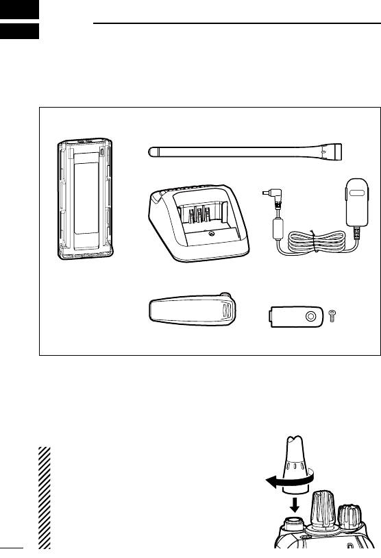
Accessory attachments ■
Flexible antenna D
Connect the flexible antenna to the antenna connector.
CAUTION:
•NEVER carry the transceiver by
holding only the antenna.
•DO NOT connect the antenna other
than listed on page 42.
•Transmitting without an antenna
may damage the transceiver.
Supplied accessories ■
The following accessories are supplied with the transceiver.
1
1ACCESSORIES
Battery pack*
Belt clip* Connector cover
(with screws)
Battery charger* AC adapter*
* Not supplied, or the shape is different, depending on the version.
Flexible antenna
(This illustration is for the VHF type.)
2
1
ACCESSORIES
1
2
3
4
5
6
7
8
9
10
11
12
13
14
15
16
17
18
19
20
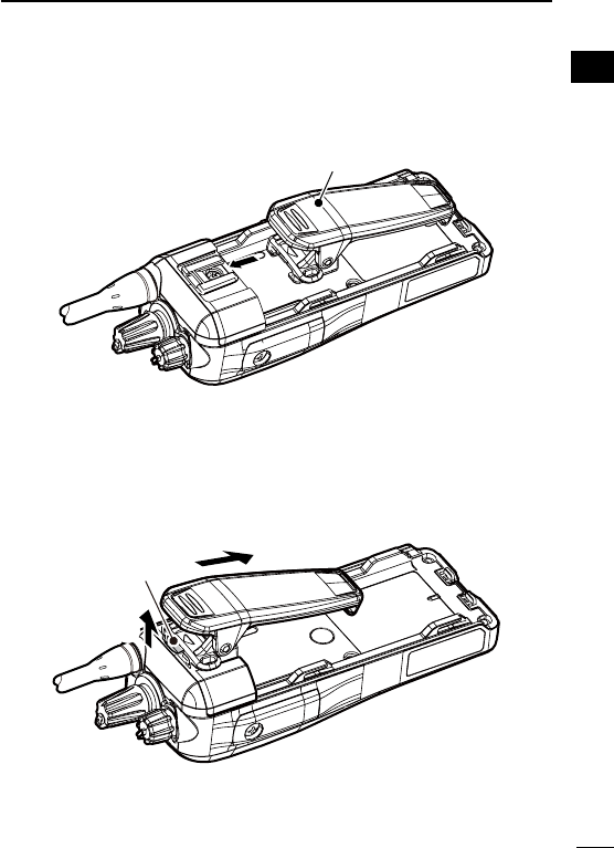
Belt clip D
To attach the belt clip:
➥ Slide the belt clip in the direction of the arrow until the belt clip
locks in place, and makes a ‘click’ sound.
Belt clip
To detach the belt clip:
Remove the battery pack from the transceiver, if it is attached. q
(p. 3)
Lift the tab up ( wq), and slide the belt clip in the direction of the
arrow (w).
w
q
Ta b
3
1ACCESSORIES
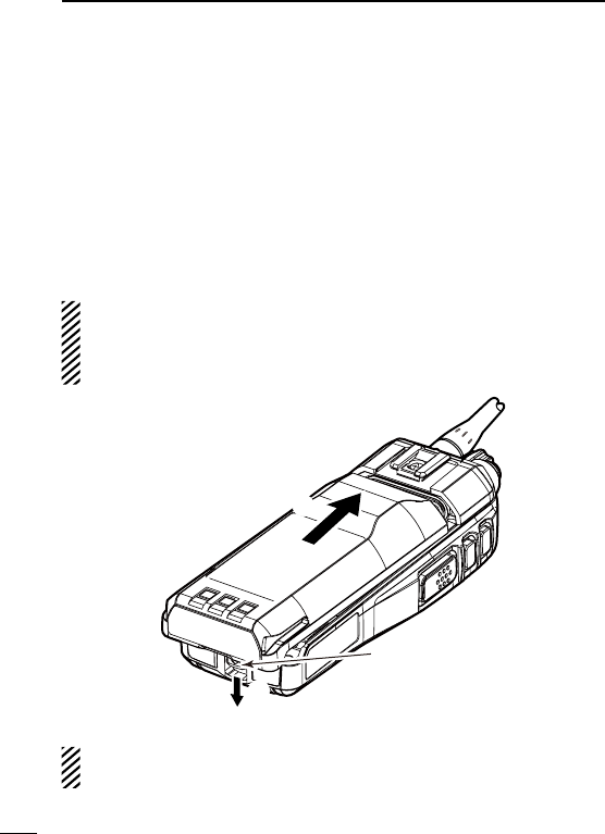
Battery pack D
To attach the battery pack:
Slide the battery pack on the back of the transceiver in the direction of
the arrow (q), then lock it with the battery release button.
•Slidethebatterypackuntilthebatteryreleasebuttonmakesa‘click’
sound.
To remove the battery pack:
Push the battery release button in the direction of the arrow (w) as
shown below. The battery pack can be removed.
NEVER remove or attach the battery pack when the transceiver
is wet or soiled. This may result water or dust getting into the
transceiver and/or battery pack and may result in them being
damaged.
q
w
Battery release
button
NOTE: Keep the battery pack terminals clean. It’s a good idea to
occasionally clean them.
4
1
ACCESSORIES
1
2
3
4
5
6
7
8
9
10
11
12
13
14
15
16
17
18
19
20
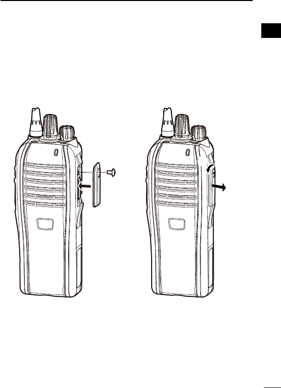
Connector cover D
Attach the connector cover when optional equipment is not used.
To attach the connector cover:
Attach the cover to the multi q
connector.
Tighten the screw. w
To detach the connector cover:
q Remove the screw with a
phillips screwdriver.
w Detach the cover to connect
the optional equipment.
w
q
q
w
5
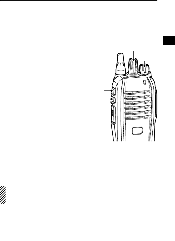
2PANEL DESCRIPTION
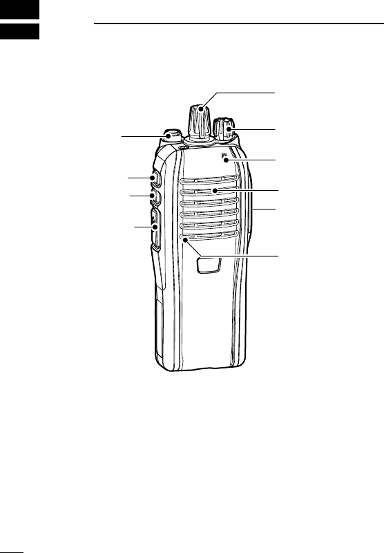
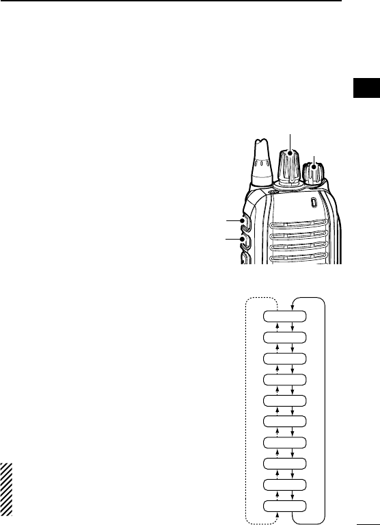
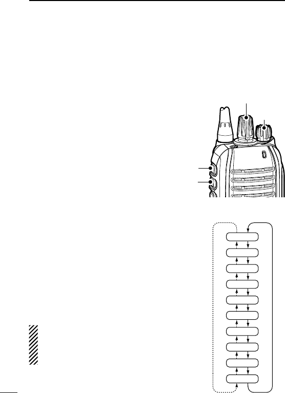
Front, top and side panels ■
Microphone
Speaker
r
w
e
q
yLOWER KEY
uUPPER KEY
tPTT SWITCH
iANTENNA
CONNECTOR
ROTARY
SELECTOR
LED INDICATOR
VOLUME
CONTROL
MULTI
CONNECTOR
q ROTARY SELECTOR
Rotate to select the preprogrammed memory channels or scan
lists, depending on the preprogramming.
w VOLUME CONTROL [VOL]
Rotate to turn the power ON or OFF, and adjust the audio level.
6
2
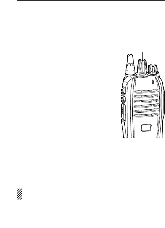
PANEL DESCRIPTION
e LED INDICATOR (pp. 7–9)
Lights red while transmitting. ➥
Lights green while receiving a signal, or when the squelch ➥
is open.
Lights/blinks orange when the matched 2/5-tone code is re- ➥
ceived, depending on the presetting.
r MULTI CONNECTOR
Connect optional equipment.
t PTT SWITCH [PTT]
Hold down to transmit; release to receive.
y LOWER KEY [Lower]
u UPPER KEY [Upper]
A desired function can be assigned by your dealer. (p. 10)
i ANTENNA CONNECTOR
Connect the antenna.
1
2
3
4
5
6
7
8
9
10
11
12
13
14
15
16
17
18
19
20
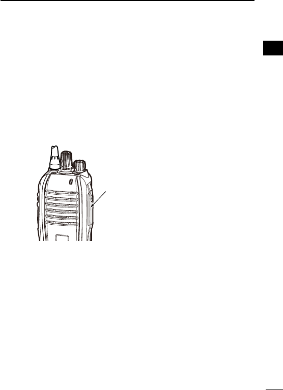
Connector cover
NOTE: Attach the cover
when optional equipment
is not used. (p. 4)
7
2PANEL DESCRIPTION
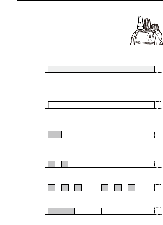
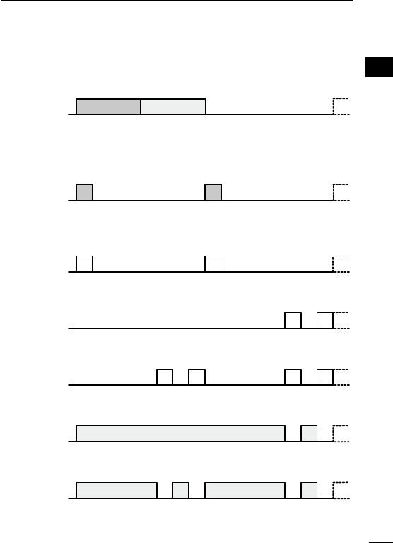
LED indicator ■
The LED indicator indicates the status of various
parameters of the transceiver as follows;
(Reference: R=Red, G=Green, O=Orange)
•TX:
Lights Red while transmitting.
R
•RXbusy:
On an analog channel, lights Green when in the noise squelch
opens. On a digital or mixed channel, lights Green while detecting
a frame synchronization.
G
•CallLED:
Turns ON when receiving a matched 2/5-tone, or receiving a Sta-
tus or SDM (Short Data Message) call.
O
•CallLED:
Blinks when receiving a matched 2/5-tone, or receiving a Status
or SDM call.
O O
•CallLED:
Blinks while waiting for a return signal.
O O O
O O O
•Success:
Blinks slowly when your call was successful.
O G
8
2
PANEL DESCRIPTION
1
2
3
4
5
6
7
8
9
10
11
12
13
14
15
16
17
18
19
20
•Callerror:
Blinks slowly when your call failed, or was refused.
O R
•Audible:
Blinks slowly after a return signal is received when in the Audible
mode*.
* Mute is released. (Received signal will be heard.)
O
O
•Fast/Slowscanorvoting:
Blinks when scanning for a channel to search for a signal or a
repeater to register on.
G G
•LowBattery1:
You should charge the battery soon. (blinks slowly)
G G
•LowBattery2:
You must charge the battery. (blinks fast)
G G G G
•TXlowBattery1:
Low Battery was detected in the TX mode.
R R
•TXlowBattery2:
Very Low Battery was detected
in the
TX mode.
R R R R

9
2PANEL DESCRIPTION
•ChannelError:
Blinks when a non-programmed channel is selected.
R O R O R O R O R O R O R O R O
•PowerON:
Blinks at transceiver startup.
R O GR O G
•TXinhibit:
Blinks while in the TX inhibit mode such as when the TOT or Lock-
out function is activated.
R O O O
•Emergency:
Blinks when an Emergency call was received.
G O R G O R G O R G O R
•EmergencyLocatorRingerSiren:
Blinks while the Emergency locator, Ringer or Siren is activated.
G O R G O R G O R G O R
LED indicator (Continued) ■

10
2
PANEL DESCRIPTION
1
2
3
4
5
6
7
8
9
10
11
12
13
14
15
16
17
18
19
20
Programmable function keys ■
The following functions can be assigned to the [Upper] and [Lower]
programmable function keys.
Consult your Icom dealer or system operator for details concerning
your transceiver’s programming.
SCAN
Push to start and cancel scanning.
•WhenthescanstartedwiththePowerONScanorAutoScanfunc-
tion, push to pause the scan. The paused scan resumes after the
specified time period has passed.
PRIORITY A CHANNEL, PRIORITY B CHANNEL
Push to select the Priority A or Priority B channel.
PRIORITY A CHANNEL (REWRITE),
PRIORITY B CHANNEL (REWRITE)
Push to select the Priority A or Priority B channel. ➥
Hold down [Prio A (Rewrite)] or [Prio B (Rewrite)] for 1 second ➥
to assign the operating channel to the Priority A or Priority B
channel, respectively.
MEMORY CHANNELS 1, 2, 3, 4
Push to directly select memory channel 1, 2, 3 or 4, if programmed.
Consult your dealer for details.
LONE WORKER (p. 25)
Hold down for 1 second to turn ON the Lone Worker function. ➥
•WhentheLoneWorkerfunctionisturnedON,andnooperationis
performed for the specified time period, the Emergency function is
automatically turned ON.
Push to turn OFF the Lone Worker function. ➥

11
2PANEL DESCRIPTION
Programmed function keys (Continued) ■
MONITOR, MONITOR (AUDIBLE)
Push to turn the CTCSS (DTCS) or 2/5-tone squelch Mute ON ➥
or OFF.
•OnlyduringLMRoperation,push to openanysquelch func-
tions, or deactivate any mute functions.
•OnlyduringPMRoperation,pushtoactivateoneortwoofthe
following functions* on each channel.
- Hold down to unmute the channel (Audible mode).
- Push to mute the channel (Inaudible mode).
- Push to send a ‘reset code’ after the communication is finished.
*Ask your dealer for details.
NOTE: The unmute condition may automatically return to the
mute condition, after a specified time period.
➥Depending on the presetting, holding down this key for 1
second cancels a scan.
LOCK
Hold down to electronically lock all programmable keys except
[Moni(Audi)], [Call] (including Call A and Call B), [Emergency], Sur-
veillance] and [Lone Worker].
HIGH/LOW (p. 24)
Select the transmit output power level temporarily or permanently,
depending on the presetting.
•Askyourdealerfortheoutputpowerlevelforeachselection.
TALK AROUND
Hold down for 1 second to turn ON the Talk Around function. ➥
•TheTalkAroundfunctionequalizesthetransmitfrequencytothe
receive frequency for transceiver-to-transceiver communication.
Push to turn OFF the Talk Around function. ➥
DTMF AUTODIAL
Push to transmit a programmed DTMF code.

12
2
PANEL DESCRIPTION
RE-DIAL
Push to transmit the last-transmitted DTMF code.
NOTE: TX memories are cleared after turning OFF the transceiver.
WIDE/NARROW
Push to toggle the IF bandwidth between Wide, Mid* or Narrow.
* Depending on the presetting, the Mid channel width may not be
selectable. Ask your dealer for details.
CALL, CALL A, CALL B
Push to transmit a 2/5-tone code.
•Tonecalltransmissionmaybenecessarybeforeyoucallanothersta-
tion, depending on your signalling system.
•[Call A] and/or [Call B] keys may be selectable when your system
employs selective ‘Individual/Group’ calls. Ask your dealer which call
is assigned to each key.
EMERGENCY
Hold down for specified time period to transmit an emergency call.
•Theemergencycalltransmitswithbeeps,andtheLEDlightsred.
•The transceiver can transmit an emergency call without the beep
sounding and the LED indicator lighting. Ask your dealer for details.
•If you want to cancel the emergency call, hold down the key again
before transmitting the call.
•Theemergencycallistransmittedonetimeonly,orrepeatedlyuntilre-
ceiving an acknowledgement signal, or until the power is turned OFF.
When a matched 5-tone code signal is received, the emergency func-
tion can be cancelled, depending on the presetting. (PMR operation
only)
SURVEILLANCE
Hold down for 1 second to turn ON the Surveillance function. ➥
•WhenthisfunctionisturnedON,thebeepisnotheardandtheLED
does not light when a signal is received, or a key is pushed.
Push to turn OFF the Surveillance function. ➥
1
2
3
4
5
6
7
8
9
10
11
12
13
14
15
16
17
18
19
20

Programmed function keys (Continued) ■
SIREN
Hold down for 1 second to emit a siren sound.
This function can be used for situations other than an emergency
alert, such as a security alarm for example.
The transceiver emits the siren sound until the power is turned
OFF.
SCRAMBLER
Hold down for 1 second to turn ON the Voice Scrambler function ➥
while operating in the digital mode.
Push to turn OFF the Voice Scrambler function. ➥
ANNOUNCE
Push to turn the Channel Announce function ON or OFF.
•WhenthisfunctionisturnedON,thetransceiverannouncestheposi-
tion of [ROTARY SELECTOR] between 1 and 16 when rotating [RO-
TARY SELECTOR] to a desired number.
13
2PANEL DESCRIPTION

14
3
BASIC OPERATION
1
2
3
4
5
6
7
8
9
10
11
12
13
14
15
16
17
18
19
20
Turning ON the power ■
Prior to using the transceiver for the first time, the battery pack
must be fully charged for optimum life and operation. (p. 33)
Rotate [VOL] to turn ON the power. ➥
[VOL]

Channel selection ■
Several types of channel selections are available. Methods may dif-
fer, depending on the presetting.
To select a desired operating channel, do one of the following.
•Rotate[ROTARYSELECTOR].
•Pushoneofthememorychannelkeys,[MR-CH1]to[MR-CH4].
•Push[PrioA],[PrioB],[PrioA(Rewrite)]or[PrioB(Rewrite)].
AUTOMATIC SCAN TYPE:
Selecting a channel is not necessary. When turning ON the power,
the transceiver automatically starts scanning. Scanning stops when
a signal is detected.
Voting Operation D
The transceiver automatically starts scanning when a zone, speci-
fied for the voting operation, is selected.
The voting scan detects the signal of the repeater and automati-
cally selects the strongest station.
15
3BASIC OPERATION
16
3
BASIC OPERATION
1
2
3
4
5
6
7
8
9
10
11
12
13
14
15
16
17
18
19
20
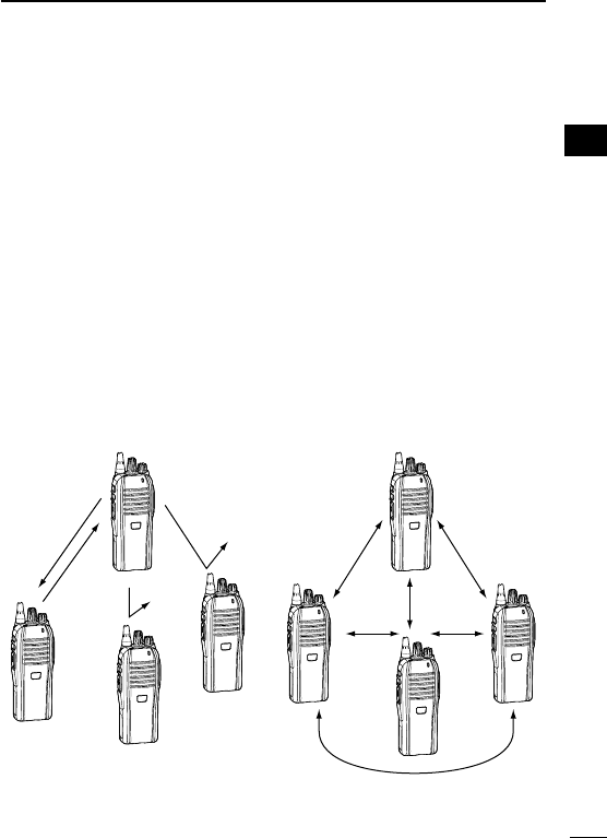
Call procedure ■
When your system employs tone signalling (excluding CTCSS and
DTCS), the tone call procedure may be necessary prior to voice
transmission. The tone signalling that is employed in the transceiver
may be a selective calling system, which allows you to call only
specific station(s), and prevents unwanted stations from contacting
you.
Select a desired TX code channel or 2/5-tone code, according to q
your System Operator’s instructions.
•Thismaynotbenecessary,dependingontheprogramming.
Push [Call] (assigned to one of the dealer programmable keys.) w
(p. 12)
After transmitting a 2/5-tone code, the remainder of your com- e
munication can be carried out normally.
Selective calling Non-selective calling

17
3BASIC OPERATION
Receiving and transmitting ■
CAUTION: Transmitting without an antenna will damage the
transceiver. See page 1 for antenna attachment.
Receiving:
Rotate [VOL] to turn ON the power. q
Rotate [ROTARY SELECTOR], or push one of the memory w
channel keys, [MR-CH 1] to [MR-CH 4], to select a channel.
When receiving a call, adjust the audio output to a comfortable e
listening level.
NOTE: When a matched RX code signal is received, the trans-
ceiver automatically transmits its microphone audio for a speci-
fied time period, depending on the presetting. Ask your dealer
for details.
Transmitting:
Wait for the channel to become clear to avoid interference.
While holding down [PTT], speak into the microphone at a nor- q
mal voice level.
Release [PTT] to receive. w
IMPORTANT: To maximize the readability of your signal;
1. Pause briefly after pushing [PTT].
2.
Hold the microphone 5 to 10 cm
(2 to 4 inches)
from your
mouth, then speak at a normal voice level.

18
3
BASIC OPERATION
1
2
3
4
5
6
7
8
9
10
11
12
13
14
15
16
17
18
19
20
Transmitting notes D
•Transmitinhibitfunction
The transceiver has several inhibit functions, which restrict trans-
mission under the following conditions:
- The channel is muted. (PMR operation only)
- The channel is busy.
- A signal with an unmatched (or matched) CTCSS (or DTCS) tone is
received.
- The selected channel is a ‘receive only’ channel.
•Time-outtimer
After continuously transmitting longer than the preprogrammed time
period, the time-out timer activates, and stops further transmitting.
•Penaltytimer
Once the time-out timer activates, transmitting is further inhibited for
a time period determined by the penalty timer.
•PTTIDcall
The transceiver automatically sends the ID code (5-tone, DTMF,
BIIS or dPMR operations) when [PTT] is pushed (beginning of the
transmission) and/or released (end of transmission), depending on
the presetting.

DTMF transmission D
If the transceiver has [DTMF Autodial] assigned to it, the automatic
DTMF transmission function is usable.
Push [DTMF Autodial] to transmit the DTMF code. ➥
Receiving a Stun, Kill and Revive command D
The dispatcher can send a signal that will stun, kill or revive your
transceiver.
When the Stun command is received, a beep sounds*, and the
transceiver becomes unusable. Receiving a Revive command is
necessary to operate the transceiver again in this case.
When the Kill command is received, a beep sounds*, and the trans-
ceiver becomes unusable. Cloning the transceiver is necessary to
operate the transceiver again in this case.
* Depending on the presetting. Ask your dealer for details.
19
3BASIC OPERATION
Setting the microphone gain ■
Adjusts the microphone gain.
Rotate [VOL] to turn the trans- q
ceiver power OFF.
Set [ROTARY SELECTOR] to w
Channel 16.
While holding down [Upper], ro- e
tate [VOL] to turn ON the power
and enter the microphone gain
adjustment mode.
Push [Upper] to increase, or r
push [Lower] to decrease the
microphone gain.
•Theadjustablerangeis1(mini-
mum) to 4 (maximum).
•A beep sounds after pushing
[Upper] or [Lower].
An error beep sounds if you try
to decrease more than 1 or try to increase more than 4.
Therefore, you can determine the current level setting by the type
of beep that sounds.
Rotate [VOL] to turn the power OFF, then ON again to exit the t
microphone gain adjustment mode.
NOTE:
This operation may not be available, depending on the preset-
ting. Ask your dealer for details.
20
3
BASIC OPERATION
1
2
3
4
5
6
7
8
9
10
11
12
13
14
15
16
17
18
19
20
[Upper]
[VOL]
[ROTARY SELECTOR]
[Lower]
Setting the squelch level ■
The squelch circuit mutes the received audio signal, depending on
the signal strength.
Rotate [VOL] to turn OFF the q
transceiver power.
Set [ROTARY SELECTOR] to w
any channel other than Chan-
nel 16.
While holding down [Upper], ro- e
tate [VOL] to turn ON the power
and enter the squelch level ad-
justment mode.
Push [Upper] to increase the r
squelch level (tight squelch), or
push [Lower] to decrease the
squelch level (loose squelch).
•Theadjustablerangeis0(loose
squelch) to 9 (tight squelch).
•Abeepsoundsafterpushing[Upper]or[Lower].
An error beep sounds if you try to decrease more than 0 or try to
increase more than 9.
Therefore, you can determine the current level setting by the type
of beep that sounds.
Rotate [VOL] to turn the power OFF, then ON again to exit the t
squelch level adjustment mode.
NOTE: This operation may not be available, depending on the
presetting. Ask your dealer for details.
21
3BASIC OPERATION
[Upper]
[VOL]
[ROTARY SELECTOR]
[Lower]
Setting the Beep level ■
The beep function can be turned ON or OFF, and its level can be
adjusted between 1 and 5, or 1 (linked) and 5 (linked). When a
Linked option is selected, the beep level is adjustable with [VOL].
Rotate [VOL] to turn OFF the q
transceiver power.
Set [ROTARY SELECTOR] to w
any channel other than Chan-
nel 16.
While holding down [Lower], ro- e
tate [VOL] to turn ON the power
and enter the beep level adjust-
ment mode.
Push [Upper] to change the r
beep level, or push [Lower] to
turn the beep function ON or
OFF.
•Theadjustablerangeis1to5or
1 (Linked) to 5 (Linked).
•A beep sounds after pushing
[Upper] or [Lower]. Therefore,
you can determine the current
level setting by the type of beep
that sounds.
Rotate [VOL] to turn the power t
OFF, then ON again to exit the
beep level adjustment mode.
NOTE: This operation may not
be available, depending on the
presetting. Ask your dealer for
details.
22
3
BASIC OPERATION
1
2
3
4
5
6
7
8
9
10
11
12
13
14
15
16
17
18
19
20
[Upper]
[VOL]
[ROTARY SELECTOR]
[Lower]
2
5
4
3
1
5 (Linked)
4 (Linked)
3 (Linked)
2 (Linked)
1 (Linked)
[Lower]
operation
[Upper]
operation
23
3BASIC OPERATION
Setting the Ringer level ■
The Ringer level can be adjusted between 1 and 5, or 1 (Linked)
and 5 (Linked). When a Linked option is selected, the Ringer level
is adjustable with [VOL].
Rotate [VOL] to turn OFF the q
transceiver power.
Set [ROTARY SELECTOR] to w
Channel 16.
While holding down [Lower], ro- e
tate [VOL] to turn ON the power
and enter the Ringer level ad-
justment mode.
Push [Upper] to increase, or r
push [Lower] to decrease the
Ringer level.
•Theadjustablerangeis1to5or
1 (Linked) to 5 (Linked).
•A beep sounds after pushing
[Upper] or [Lower]. Therefore,
you can determine the current
level setting by the type of beep
that sounds.
Rotate [VOL] to turn the power t
OFF, then ON again to exit the
beep level adjustment mode.
NOTE: This operation may not
be available, depending on the
presetting. Ask your dealer for
details.
[Upper]
[VOL]
[ROTARY SELECTOR]
[Lower]
2
5
4
3
1
5 (Linked)
4 (Linked)
3 (Linked)
2 (Linked)
1 (Linked)
[Lower]
operation
[Upper]
operation

24
3
BASIC OPERATION
1
2
3
4
5
6
7
8
9
10
11
12
13
14
15
16
17
18
19
20
Output power level selection ■
If the transceiver has [High/Low] assigned to it, the transmit output
power level can be selected, depending on the presetting.
When the battery voltage drops to a low power level and the LED
indicator status is “Low Battery 2,” the output power automatically
switches to “Low 1.” (pp. 8, 11)
Push [High/Low] to select the transmit output power level. ➥
•Onebeepsoundswhen“Low1”isselected.
•Twobeepssoundwhen“Low2”isselected.
•Threebeepssoundwhen“High”isselected.
Priority A channel selection ■
When one of the following operations is performed, the transceiver
automatically selects the Priority A channel.
•TurningthepowerON
The Priority A channel is selected each time the transceiver power
is turned ON.
•Autoreset
The Priority A channel is selected when the Auto Reset timer
ends.

25
3BASIC OPERATION
Lone Worker Emergency Call ■
When the Lone Worker function is turned ON, and no operation is
performed for the specified time period*, the transceiver enters the
emergency mode, and then the countdown for the emergency call
transmission starts.
After the specified time period* has passed, an emergency call is
automatically transmitted once, or repeatedly*.
If someone operates the transceiver before the call is transmitted, the
transceiver exits the emergency mode, and the emergency call is can-
celled.
* Depending on the presetting. Ask your dealer for details.
Hold down [Lone Worker] for 1 second to turn ON the Lone q
Worker function.
w Push [Lone Worker] to turn OFF the Lone Worker function.
Man Down Emergency Call ■
When the transceiver has been left in a horizontal position for the
preprogrammed time period, the transceiver enters the emergency
mode, and then the countdown for the emergency call transmission
starts.
After the preprogrammed time period, an emergency call is auto-
matically transmitted once, or repeatedly, depending on the pre-
programmed settings.
If the transceiver is placed in a vertical position before the first
transmission, the transceiver exits the emergency mode and the
emergency call is cancelled.

26
3
BASIC OPERATION
1
2
3
4
5
6
7
8
9
10
11
12
13
14
15
16
17
18
19
20
Emergency Call ■
When [Emergency] is held down for the specified time period*, the
emergency signal is transmitted once, or repeatedly, on the speci-
fied emergency channel.
* Depending on the presetting. Ask your dealer for details.
A repeat emergency signal is automatically transmitted until you
turn OFF the power.
Depending on the preprogrammed settings, receiving a matching
5-tone code cancels the transmission.
When no emergency channel is specified, the signal is transmitted
on the previously selected channel.
If you want to cancel the emergency call, hold down [Emergency]
again before transmitting the call.
If your transceiver is programmed for Silent operation, you can
transmit an Emergency call without the beep sounding and the LED
indicator lighting.
IMPORTANT: We recommend you set an emergency channel in-
dividually to provide for reliable emergency call operation.
NOTES D
Depending on the presetting, the following functions are automati-
cally activated. Ask your dealer for details.
•AutoTXfunction
After the emergency call transmission, audio from the microphone
is automatically transmitted for a specified time period.*
•AutoRXfunction
After the emergency call transmission, the transceiver stands by in
the Audible mode for the specified time period.*
* Depending on the presetting. Ask your dealer for details.

27
4dPMR OPERATION
dPMR operation ■
The transceiver providing digital Private Mobile Radio (dPMR)
operation meets the 6.25 kHz bandwidth requirements for narrow
band operation. This increases the efficiency of channel allocation
and use of the spectrum.
NOTE: During dPMR operation, BIIS 1200 operation is dis-
abled.
Receiving a call ■
Receiving an Individual call D
When an Individual call is received: q
•Thetransceiverwillautomaticallytransmitareturnsignal.
•TheLEDindicatorblinksorange.
•Beepssoundandthemuteisreleased.
Hold down [PTT], then speak into the microphone. w
Release [PTT] to receive. e
After the communication is finished, push [Clear] to send a ‘Dis- r
connect’ signal to terminate the connection.
NOTE: The LED indicator and Beeps may differ, depending on
the presetting. Ask your dealer for details.

28
4
dPMR OPERATION
1
2
3
4
5
6
7
8
9
10
11
12
13
14
15
16
17
18
19
20
Receiving a Group call D
When a Group call is received: q
•TheLEDindicatorblinksorange.
•Beepssoundandthemuteisreleased.
Hold down [PTT], then speak into the microphone. w
NOTE: Only one station is allowed to speak at the same
time.
Release [PTT] to receive. e
After the communication is finished, push [Clear] to send a ‘Dis- r
connect’ signal to terminate the connection.
NOTE: The LED indicator or Beeps may differ, depending on the
presetting. Ask your dealer for details.
Receiving a Stun, Kill or Revive D
If an individual Stun or Kill call is received, the transceiver will au-
tomatically transmit an acknowledgement, and then you cannot re-
ceive* or transmit.
* Reception may be available, depending on the presetting of the re-
ceived stun command.
When a Stun command is received: ➥
•Thetransceivercannotbeoperateduntiltheindividualrevivecallis
received or until data cloning is performed.
•Evenif[ROTARYSELECTOR]ischanged,thetransceiverwillstay
on the same channel the Stun command received on.
When a Kill command is received: ➥
•TheLEDindicatoralternatelyblinksredandgreen.
•Thetransceivercannotbeoperateduntildatacloningisperformed.
Ask your dealer for details.
NOTE: Depending on the presetting, the transceiver may ignore
the Stun, Revive and Kill commands, that are from a non-speci-
fied station.

29
4dPMR OPERATION
Receiving a call (Continued) ■
Receiving a Status Polling call D
If a Status Polling call is received, the transceiver will automatically
transmit its current status.*
Receiving an Ambience Listening call D
If an Individual call with an Ambience Listening command is re-
ceived from a specified station, the transceiver will automatically
transmit its microphone audio.*
*Depending on the presetting.
NOTE: If the transceiver receives an Ambience Listening com-
mand from a station other than the specified one, the call will be
ignored, and the transceiver will not transmit its microphone au-
dio.
Receiving an Emergency call D
When an Emergency call is received:
•Thetransceiverwillautomaticallytransmita return signal.
•TheLEDindicatorblinksorange.
•Beepssoundandthemuteisreleased.
Push [Clear] to return to the standby mode.
Talk back function D
The Talk Back function allows you to select the same call mode
(Analog or Digital) as the received call.
NOTE: When this function is not activated, the transceiver al-
ways transmits analog signals on “Mixed-Analog” channels, and
digital signals on “Mixed-Digital” channels.
•Onthesechannels,thetransceivercan receiveboth analogand
digital signals, regardless of the Talk Back function.

30
4
dPMR OPERATION
1
2
3
4
5
6
7
8
9
10
11
12
13
14
15
16
17
18
19
20
Transmitting a call ■
dPMR operation allows you to make a call to a specific station (In-
dividual call) or to a particular group (Talkgroup call). Other digital
mode transceivers on the channel will not receive a call that does
not match their individual or talkgroup ID and/or CC.
Transmitting a Voice call D
Rotate [ROTARY SELECTOR], or push one of the memory chan- q
nel keys, [MR-CH 1] to [MR-CH 4], to select a desired channel,
Individual ID or Talkgroup ID, depending on the presetting.
Push [PTT] or [Call] to make a Voice call. w
•TheLEDindicatorlightsredwhiletransmitting.
•TheLEDindicatorfastblinksorange.
•After an acknowledgement is received, the LED indicator slowly
blinks orange in the Audible mode, or it goes OFF when no ac-
knowledgement is received.
Hold down [PTT], then speak at your normal voice level. e
•TheLEDindicatorlightsredwhiletransmitting.
Release [PTT] to receive. r
After you finish your communication, push [Clear] to send a ‘Dis- t
connect’ signal to terminate the connection.

31
4dPMR OPERATION
Transmitting a call (Continued) ■
Transmitting an Emergency call D
When [Emergency] is held down for the specified time period, the
emergency signal (digital command) is transmitted once or repeat-
edly* on the specified emergency channel. When no emergency
channel is specified, the signal is transmitted on the operating
channel.
* When the Repeat Cancel function is ON, the transceiver cancels
repeating after receiving a return signal.
When the Repeat Cancel function is OFF, the transceiver repeats
calling according to the number of repeat cycles, even after receiv-
ing a return signal.
Individual or Talkgroup call types of emergency calls can be pre-
set. If the call type is not preset, the default or selected call type
is used.
If you want to cancel the emergency call, hold down [Emergency]
again before transmitting the call.
If your transceiver is programmed for Silent operation, you can
transmit an Emergency call without the beep sounding and the LED
indicator lighting.
The transceiver can also be programmed to keep the microphone
open during an emergency call, so others can monitor the situa-
tion.
Ask your dealer for details.
IMPORTANT: We recommend you set an emergency channel
individually to provide the certain emergency call operation.
NOTE: If the Digital Request Ack function is activated, the trans-
ceiver transmits the emergency call with a request to send back
a return signal.

32
4
dPMR OPERATION
1
2
3
4
5
6
7
8
9
10
11
12
13
14
15
16
17
18
19
20
Status message transmission ■
The status message can automatically be transmitted.
The status message is transmitted when the transceiver is turned
ON or OFF.
- Select a status message to be transmitted in ‘Power ON Status’
or ‘Power OFF Status’ items, respectively.
- Select a target station ID in ‘Power Status ID’.
Scrambler function ■
The voice scrambler function provides private communication be-
tween stations while operating in the digital mode.
Hold down [Scrambler] for 1 second to turn ON the Scrambler q
function.
Push [Scrambler] to turn OFF the Scrambler function. w

33
5BATTERY CHARGING
Caution ■
Misuse of Li-ion batteries may result in the following hazards:
smoke, fire, or the battery may rupture. Misuse can also cause
damage to the battery or degradation of battery performance.
R DANGER! NEVER short terminals (or charging terminals) of the
battery pack. Also, current may flow into nearby metal objects such
as a necklace, so be careful when placing battery packs (or the
transceiver) in handbags, etc.
Simply carrying with or placing near metal objects such as a neck-
lace, etc. may cause shorting. This may damage not only the bat-
tery pack, but also the transceiver.
Battery caution D
R DANGER! DO NOT hammer or otherwise impact the battery. Do
not use the battery if it has been severely impacted or dropped, or if
the battery has been subjected to heavy pressure. Battery damage
may not be visible on the outside of the case. Even if the surface
of the battery does not show cracks or any other damage, the cells
inside the battery may rupture or catch fire.
R DANGER! NEVER use the transceiver or the battery if either
one is damaged, shows cracks, bruises or is deformed.
R DANGER! NEVER use or leave battery packs in areas with
temperatures above +55˚C (+131°F). High temperature buildup in
the battery, such as could occur near fires or stoves, inside a sun
heated car, or in direct sunlight may cause the battery to rupture or
catch fire. Excessive temperatures may also degrade battery per-
formance or shorten battery life.

34
5
BATTERY CHARGING
1
2
3
4
5
6
7
8
9
10
11
12
13
14
15
16
17
18
19
20
R DANGER! DO NOT expose the battery to rain, snow, seawater,
or any other liquids. Do not charge or use a wet battery. If the bat-
tery gets wet, be sure to wipe it dry before using. The battery is not
waterproof.
R DANGER! NEVER incinerate used battery packs, since internal
battery gas may cause them to rupture, or may cause an explosion.
R DANGER! NEVER solder the battery terminals or NEVER mod-
ify the battery pack. This may cause heat generation, and the bat-
tery may rupture, emit smoke or catch fire.
R DANGER! Use the battery only with the transceiver for which it is
specified. Never use a battery with any other equipment, or for any
purpose that is not specified in this instruction manual.
R DANGER! If fluid from inside the battery gets in your eyes, blind-
ness can result. Rinse your eyes with clean water, without rubbing
them, and see a doctor immediately.
R
WARNING! Immediately stop using the battery if it emits an ab-
normal odor, heats up, or is discolored or deformed. If any of these
conditions occur, contact your Icom dealer or distributor.
R
WARNING! Immediately wash, using clean water, any part of
the body that comes into contact with fluid from inside the battery.
R
WARNING! NEVER put the battery in a microwave oven, high-
pressure container, or in an induction heating cooker. This could
cause a fire, overheating, or cause the battery to rupture.
CAUTION: Always use the battery within the specified temperature
range; –20°C to +55°C (–4°F to +131°F). Using the battery out of its
specified temperature range will reduce the battery’s performance
and battery life.

35
5BATTERY CHARGING
CAUTION: Shorter battery life could occur if the battery is left fully
charged, completely discharged, or in an excessive temperature
environment (above +50˚C; +122°F) for an extended period of time.
If the battery must be left unused for a long time, it must be de-
tached from the radio after discharging.
You may use the battery until the remaining capacity is about half,
then keep it safely in a cool dry place within the temperature range
as shown below:
–20˚C to +50˚C (–4°F to +122°F) (up to a month)
–20˚C to +40˚C (–4°F to +104°F) (up to three months)
–20˚C to +20˚C (–4°F to +68°F) (up to a year)
BE SURE to replace the battery with a new one after five years,
even if still holds a charge. The inside battery material will deterio-
rate after a period of time, even with little use.

36
5
BATTERY CHARGING
1
2
3
4
5
6
7
8
9
10
11
12
13
14
15
16
17
18
19
20
Charging caution D
R DANGER! NEVER charge the battery pack in areas with ex-
tremely high temperatures, such as near fires or stoves, inside
a sun heated car, or in direct sunlight. In such environments, the
safety/protection circuit in the battery will activate, causing the bat-
tery to stop charging.
R
WARNING! DO NOT charge or leave the battery in the battery
charger beyond the specified time for charging. If the battery is not
completely charged by the specified time, stop charging and re-
move the battery from the battery charger. Continuing to charge the
battery beyond the specified time limit may cause a fire, overheat-
ing, or the battery may rupture.
R
WARNING! NEVER insert the transceiver (battery attached to
the transceiver) into the charger if it is wet or soiled. This could
corrode the battery charger terminals or damage the charger. The
charger is not waterproof.
CAUTION: DO NOT charge the battery outside of the specified
temperature range: BC-212EX (+10˚C to +40˚C; +50°F to +104°F).
Icom recommends charging the battery at +20˚C (+68°F). The bat-
tery may heat up or rupture if charged out of the specified tempera-
ture range. Additionally, battery performance or battery life may be
reduced.
CAUTION: DO NOT place the charger on unstable surfaces.
The BC-212EX will not fully charge a battery pack (about 90% of
fully charged condition) for battery protection.
37
5BATTERY CHARGING
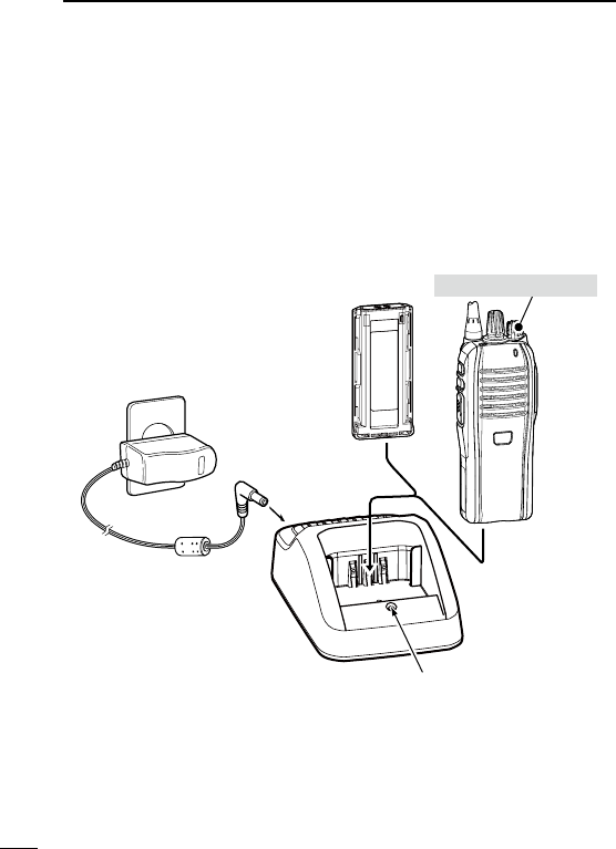
Battery charger ■
Using the BC-212EX to rapid charge the BP-277EX D
The BC-212EX rapidly charges the Li-ion battery pack.
Charging time: Approximately 2.5 hours (for the BP-277EX)
Following item is additionally required:
•AnACadapter(notsuppliedwithsomeversions)
Status indicator
• Lights orange:
While charging.
• Lights green:
Charging is completed.
AC adapter
(A different type,
or no AC adapter
is supplied, de-
pending on the
charger version.)
Battery pack
Transceiver
Tu rn OFF the power
38
5
BATTERY CHARGING
1
2
3
4
5
6
7
8
9
10
11
12
13
14
15
16
17
18
19
20
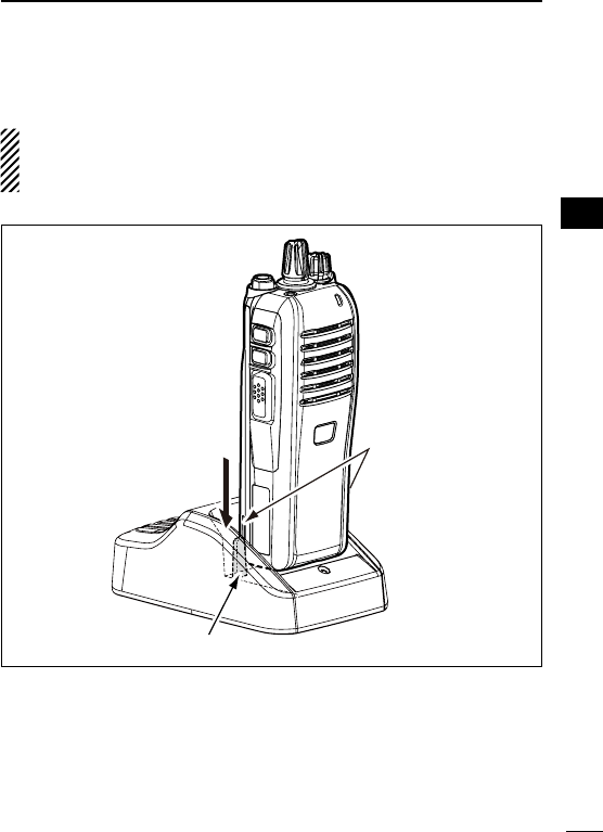
IMPORTANT:
Ensure the grooves on the battery pack are correctly aligned
with the guide rails inside the charger.
Guide rail
Grooves
39
6SPEAKER MICROPHONE
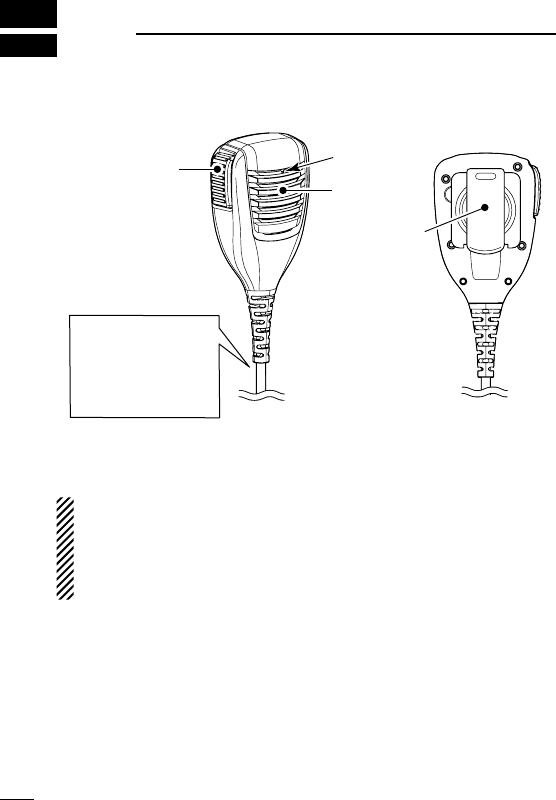
Optional HM-203EX description ■
Speaker
Belt clip
Microphone
PTT SWITCH
Hold down to
transmit, release
to receive.
Tu rn OFF the trans-
ceiver power when
connecting or dis-
connecting the mi-
crophone.
NEVER immerse the connector in water. If the connector becomes
wet, be sure to dry it BEFORE connecting it to the transceiver.
NOTE: The microphone is located at the top of the speaker mi-
crophone, as shown in the diagram above. To maximize the
readability of your transmitted signal (voice), hold the micro-
phone approximately 5 to 10 cm
(2 to 4 inches)
from your mouth,
and speak at a normal voice level.
40
6
SPEAKER MICROPHONE
1
2
3
4
5
6
7
8
9
10
11
12
13
14
15
16
17
18
19
20
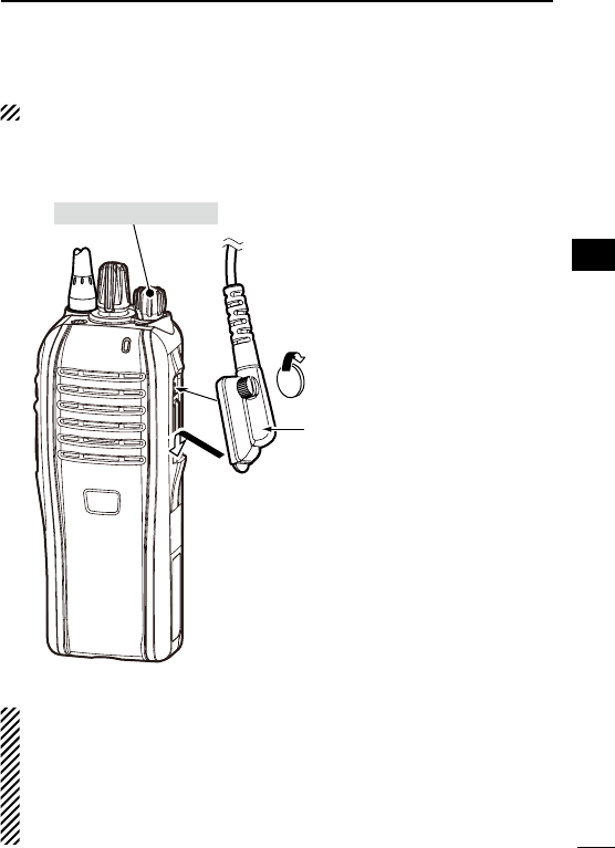
To attach ■
BE SURE to turn OFF the power before attaching.
Attach the connector of the speaker microphone into the multi con-
nector on the transceiver, and tighten the screw.
Tu rn OFF the power
IMPORTANT: KEEP the connector cover attached to the trans-
ceiver when the speaker microphone is not in use. (p. 4)
Water will not get into the transceiver even if the cover is not at-
tached, however, the terminals (pins) will become rusty, or the
transceiver will function abnormally if the connector becomes
wet.
CAUTION: Attach the multi
connector snugly, but do
not overtighten.
A loose connection will al-
low water intrusion into the
connector. A overtightened
connector will damage the
connector pins in the trans-
ceiver.

41
7OPTIONS
BATTERY PACK D
•BP-277EXL I -I O N B AT T E R Y P A C K
Voltage: 7.4 V
Capacity: 1800 mAh (min.) 1900 mAh (typ.)
Battery life
VHF UHF
Digital mode
Analog mode
Digital mode
Analog mode
21.5 hrs. 21 hrs. 19 hrs.
*
When the power save function is turned ON, and the operating time is
calculated under the following conditions;
TX : RX : standby = 5 : 5 : 90
D BELT CLIP
•MB-94EXB E LT C L I P
Exclusive alligator-type belt clip.
D CHARGER
•BC-212EXD E S K T O P C H A R G E R + BC-123S A C A D A P T E R
To rapid charge the Li-ion battery pack. An AC adapter may be
supplied with the charger, depending on the version.
Charging time: Approximately 2.5 hours for the BP-277EX.

42
7
OPTIONS
1
2
3
4
5
6
7
8
9
10
11
12
13
14
15
16
17
18
19
20
D ANTENNAS
•FA-SC25U/FA-SC57U/FA-SC72U/FA-SC01U
FA-SC25V/FA-SC55V A N T E N N A S
FA-SC25U: 400–430 MHz FA-SC57U: 430–470 MHz
FA-SC72U: 470–520 MHz FA-SC01U: 350–400 MHz
FA-SC25V: 136–155 MHz FA-SC55V: 146–174 MHz
D SPEAKER MICROPHONE
•HM-203EXS P E A K E R -M I C R O P H O N E
Combination speaker microphone that provides convenient op-
eration while hanging the transceiver on your belt.
Approved Icom optional equipment is designed for optimal performance
when used with an Icom transceiver.
Icom is not responsible for the destruction or damage to an Icom trans-
ceiver in the event the Icom transceiver is used with equipment that is
not manufactured or approved by Icom.
Some options may not be available in some countries. Please ask your
dealer for details.

43
8
SAFETY TRAINING INFORMATION
WARNING
Your Icom radio generates RF electromagnetic energy
during transmit mode. This radio is designed for and
classified as “Occupational Use Only”, meaning it must
be used only during the course of employment by indi-
viduals aware of the hazards, and the ways to minimize
such hazards. This radio is NOT intended for use by the
“General Population” in an uncontrolled environment.
This radio has been tested and complies with the FCC
and IC RF exposure limits for “Occupational Use Only”. In addition, your
Icom radio complies with the following Standards and Guidelines with
regard to RF energy and electromagnetic energy levels and evaluation
of such levels for exposure to humans:
•FCCOETBulletin65Edition97-01SupplementC,Evaluating
Compliance with FCC Guidelines for Human Exposure to Radio
Frequency Electromagnetic Fields.
•AmericanNationalStandardsInstitute(C95.1-1992),IEEEStandard
for Safety Levels with Respect to Human Exposure to Radio Fre-
quency Electromagnetic Fields, 3 kHz to 300 GHz.
•AmericanNationalStandardsInstitute(C95.3-1992),IEEERecom-
mended Practice for the Measurement of Potentially Hazardous
Electromagnetic Fields– RF and Microwave.
•Theaccessories(antennas,batteries,beltclips,speaker-micro-
phone, etc. that is listed on pages 41–42) are authorized for use
with this product. Use of accessories other than those specified may
result in RF exposure levels exceeding the FCC and IC require-
ments for wireless RF exposure.
CAUTION
To ensure that your expose to RF electromagnetic
energy is within the FCC and IC allowable limits for
occupational use, always adhere to the following
guidelines:

44
8
SAFETY TRAINING INFORMATION
1
2
3
4
5
6
7
8
9
10
11
12
13
14
15
16
17
18
19
20
•DO NOT operate the radio without a proper antenna attached, as
this may damaged the radio and may also cause you to exceed
FCC and IC RF exposure limits. A proper antenna is the antenna
supplied with this radio by the manufacturer or antenna specifically
authorized by the manufacturer for use with this radio.
•DO NOT transmit for more than 50% of total radio use time (“50%
duty cycle”). “50% duty cycle” is also applicable to VOX/PTT mode.
Transmitting more than 50% of the time can cause FCC and IC RF
exposure compliance requirements to be exceeded. The radio is
transmitting when the “LED indicator” lights red. You can cause the
radio to transmit by pressing the “PTT” switch or VOX function.
•ALWAYS keep the antenna at least 2.5 cm (1 inch) away from
the body when transmitting and only use the Icom belt-clip which
is listed on page 41 when attaching the radio to your belt, etc., to
ensure FCC and IC RF exposure compliance requirements are not
exceeded. To provide the recipients of your transmission the best
sound quality, hold the antenna at least 5 cm (2 inches) from your
mouth, and slightly off to one side.
The information listed above provides the user with the information
needed to make him or her aware of RF exposure, and what to do to as-
sure that this radio operates with the FCC
and IC
RF exposure limits of
this radio.
Electromagnetic Interference/Compatibility
During transmissions, your Icom radio generates RF energy that can
possibly cause interference with other devices or systems. To avoid such
interference, turn off the radio in areas where signs are posted to do so.
DO NOT operate the transmitter in areas that are sensitive to electro-
magnetic radiation such as hospitals, aircraft, and blasting sites.
Occupational/Controlled Use
The radio transmitter is used in situations in which persons are exposed as
consequence of their employment provided those persons are fully aware
of the potential for exposure and can exercise control over their exposure.

45
8SAFETY TRAINING INFORMATION
Votre radio Icom produit une énergie électromagnétique
de radiofréquences (RF), en mode de transmission.
Cette radio est conçue pour un «usage professionnel
seulement» et classée comme tel, ce qui signifie qu’elle
doit être utilisée uniquement dans le cadre d’un travail
par des personnes conscientes des dangers et des me-
sures visant à minimiser ces dangers. Elle N’EST PAS conçue pour une
«utilisation grand public», dans un environnement non contrôlé.
Cet appareil a été évalué et jugé conforme, aux limites d’exposition
aux RF de la FCC et d’IC, pour une «utilisation grand public». En outre,
votre radio Icom satisfait les normes et directives qui suivent en matière
de niveaux d’énergie et d’énergie électromagnétique de RF et d’évalua-
tion de tels niveaux en ce qui concerne l’exposition humaine:
•SupplémentC,édition97-01,duBulletinOETn°65delaFCC,«Eva-
luating Compliance with FCC Guidelines for Human Exposure to
Radio Frequency Electromagnetic Fields».
•Norme de l’American National Standards Institute (ANSI): IEEE
C95.1-1992 sur les niveaux de sécurité compatibles avec l’exposition
humaine aux champs électromagnétiques de radiofréquences (3 kHz
à 300 GHz).
•Normedel’ANSI:IEEEC95.3-1992surlaméthoded’évaluationre-
commandée du champ magnétique potentiellement dangereux des
radiofréquences et des micro-ondes.
•Lesaccessoiresillustrésàlap.41–42sontapprouvéspouruneutilisa-
tion avec ce produit. L’utilisation d’accessoires autres que ceux précisés
peut entraîner des niveaux d’exposition aux RF supérieures aux limites
établies par la FCC et d’IC en matière d’exposition aux RF sans fil.
Afin de vous assurer que votre exposition à une
énergie électromagnétique de RF se situe dans
les limites permises par la FCC et d’IC pour une
utilisation grand public, veuillez en tout temps
respecter les directives suivantes:

46
8
SAFETY TRAINING INFORMATION
1
2
3
4
5
6
7
8
9
10
11
12
13
14
15
16
17
18
19
20
•NE PAS faire fonctionner la radio sans qu’une antenne appropriée y soit
fixée, car ceci risque d’endommager la radio et causer une exposition su-
périeure aux limites établies par la FCC
et d’IC
. L’antenne appropriée est
celle qui est fournie avec cette radio par le fabricant ou une antenne spé-
cialement autorisée par le fabricant pour être utilisée avec cette radio.
• NE PAS émettre pendant plus de 50 % du temps total d’utilisation
de l’appareil («50 % du facteur d’utilisation»). La notion «50% du fac-
teur d’utilisation» s’applique également au mode VOX/PTT. Émettre
pendant plus de 50 % du temps total d’utilisation peut causer une
exposition aux RF supérieure aux limites établies par la FCC et d’IC.
Lorsque le voyant DEL rouge s’allume, cette radio est en train d’émet-
tre. La radio émettra si vous appuyez sur le bouton du microphone.
•TOUJOURS tenir l’antenne éloignée d’au moins 2,5 cm de votre corps
au moment d’émettre et utiliser uniquement l’attache pour ceinture Icom
illustrée à la p. 41, lorsque vous attachez la radio à votre ceinture, ou à
autre chose, de façon à vous assurer de ne pas provoquer une exposi-
tion aux RF supérieure aux limites fixées par la FCC et d’IC. Pour offrir
à vos interlocuteurs la meilleure qualité de transmission possible, tenez
l’antenne à au moins 5 cm de votre bouche et légèrement de côté.
Les renseignements ci-dessus fournissent à l’utilisateur toute l’information néces-
saire sur l’exposition aux RF et sur ce qu’il faut faire pour assurer que cette radio
fonctionne en respectant les limites d’exposition aux RF établies par la FCC et d’IC.
Interférence électromagnétique et compatibilité
En mode de transmission, votre radio Icom produit de l’énergie de RF
qui peut provoquer des interférences avec d’autres appareils ou sys-
tèmes. Pour éviter de telles interférences, mettez la radio hors tension
dans les secteurs où une signalisation l’exige. NE PAS faire fonctionner
l’émetteur dans des secteurs sensibles au rayonnement électromagné-
tique tels que les hôpitaux, les aéronefs et les sites de dynamitage.
Usage professionnel/contrôlé
Ce radio émetteur est utilisé dans des cas où des personnes sont expo-
sées en raison de leur travail, pourvu qu’elles soient conscientes du risque
d’exposition et qu’elles puissent exercer un contrôle sur cette exposition.

47
9FCC INFORMATION
•FORCLASSAUNINTENTIONALRADIATORS:
This equipment has been tested and found to comply with the limits
for a Class A digital device, pursuant to part 15 of the FCC Rules.
These limits are designed to provide reasonable protection against
harmful interference when the equipment is operated in a commer-
cial environment. This equipment generates, uses, and can radiate
radio frequency energy and, if not installed and used in accordance
with the instruction manual, may cause harmful interference to ra-
dio communications.
Operation of this equipment in a residential area is likely to cause
harmful interference in which case the user will be required to cor-
rect the interference at his own expense.
CAUTION: Changes or modifications to this device, not expressly
approved by Icom Inc., could void your authority to operate this
transceiver under FCC regulations.

48
MEMO
1
2
3
4
5
6
7
8
9
10
11
12
13
14
15
16
17
18
19
20

1-1-32 Kamiminami, Hirano-ku, Osaka 547-0003, Japan
A-7100D-1EX
Printed in Japan
© 2013 Icom Inc.
Printed on recycled paper with soy ink.