ICOM orporated 357000 VHF Marine Transceiver User Manual IC M506 draft 0306
ICOM Incorporated VHF Marine Transceiver IC M506 draft 0306
UserManual.wiki
>
ICOM orporated
>
357000 User Manual
User Manual
Navigation menu
Upload a User Manual
Namespaces
Wiki Guide
HTML
PDF
Info
Views
User Manual
Discussion / Help
Navigation
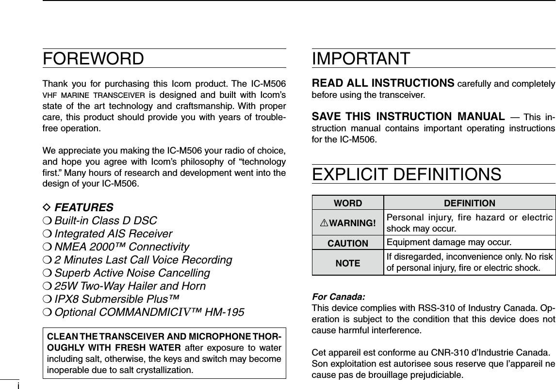
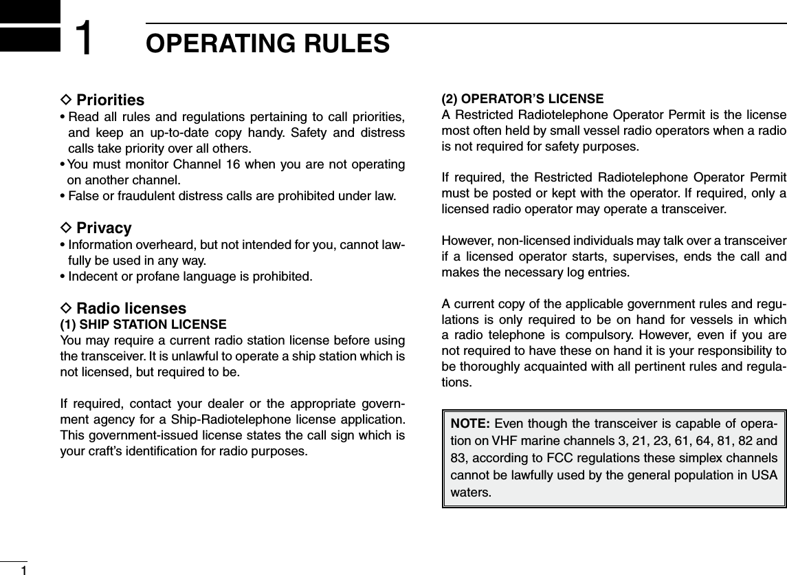
![If your vessel requires assistance, contact other vessels and the Coast Guard by sending a Distress call on Channel 16.Or, transmit your Distress call using digital selective calling on Channel 70.USING CHANNEL 16DISTRESS CALL PROCEDURE1. “MAYDAY MAYDAY MAYDAY.”2. “THIS IS ...............” (name of vessel).3. Say your call sign or other description of the vessel (AND 9 digit DSC ID if you have one).4. “LOCATED AT ...............” (your position).5. State the nature of the distress and assistance re-quired.6. Give any other information which might facilitate the rescue.USING DIGITAL SELECTIVE CALLING (Ch 70)DISTRESS CALL PROCEDURE1. While lifting up the key cover, hold down [DIS-TRESS] for 3 seconds until you hear 3 short beeps and then one long beep.2. Wait for an acknowledgment on Channel 70 from a coast station.s!FTERTHEACKNOWLEDGEMENTISRECEIVED#HANNELISautomatically selected.3. Hold down [PTT], then transmit the appropriate in-formation as listed above.iiIN CASE OF EMERGENCY](https://usermanual.wiki/ICOM-orporated/357000/User-Guide-2220780-Page-3.png)
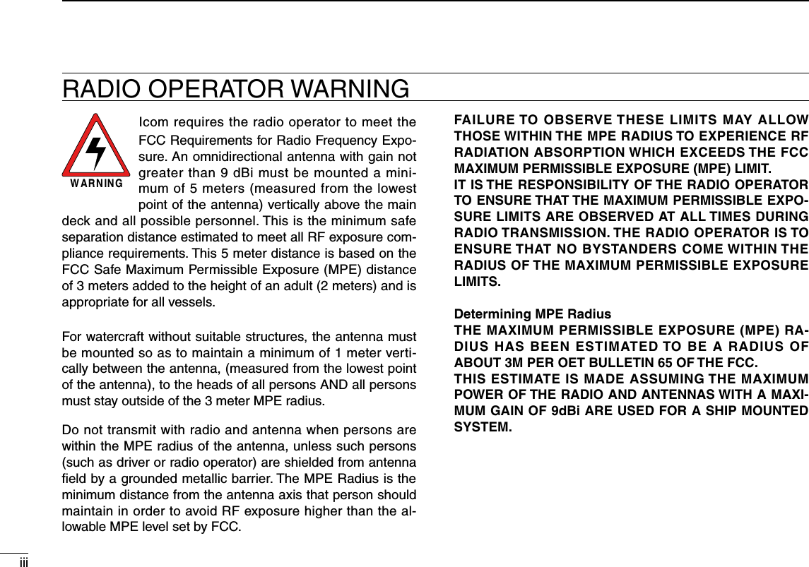
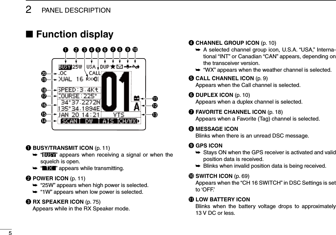
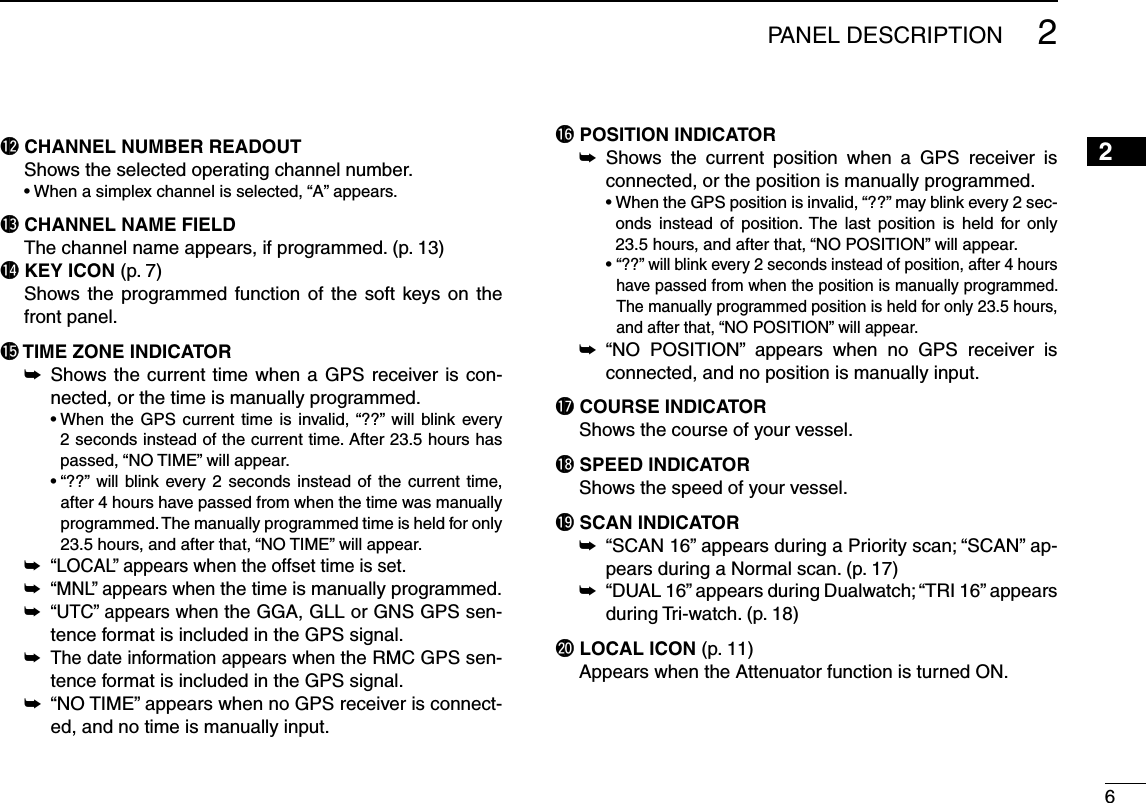
![22PANEL DESCRIPTION12345678910111213141516Front panel Nq DISTRESS KEY [DISTRESS] (pp. 23, 24) Hold down for 3 seconds to transmit a Distress call.w ENTER KEY [ENT] Push to set the input data, selected item, and so on.e LEFT AND RIGHT KEYS [Ω]/[≈] Push to switch to the previous or next key function that ±is assigned to the soft keys. (p. 7) Push to select the desired character or number in the ±table while in the channel name, position, MMSI code programming mode, and so on. (pp. 8, 13, 22)r UP AND DOWN/CHANNEL SELECT KEYS [∫CH]/[√CH] Push to select the operating channels, Menu items, ±Menu settings, and so on. While scanning, push to check Favorite channels, ±change the scanning direction or manually resume a scan. (p. 16)t CLEAR KEY [CLEAR] Push to cancel the entered data, or to return to the previ-ous screen.y MENU KEY [MENU] (p. 91) Push to enter or exit the Menu screen.u DIAL/POWER SWITCH [PWR] When the power is OFF, hold down for 1 second to turn ±ON power. (p. 11)± Hold down for 1 second to turn OFF power.± Rotate to select the operating channels, Menu items, Menu settings, and so on.± Push to set the input data, selected item, and so on..i CHANNEL 16/CALL CHANNEL KEY [16/C]± Push to select Channel 16. (p. 9)± Hold down for 1 second to select the Call channel. (p. 9) sh#!,,vAPPEARSWHENTHE#ALLCHANNELISSELECTEDCLEARMENUENTCHCHtuyweriqo!0!1Function display (p. 5)Speaker](https://usermanual.wiki/ICOM-orporated/357000/User-Guide-2220780-Page-11.png)
![32PANEL DESCRIPTIONCLEARMENUENTCHCHtuyweriqo!0!1Function display (p. 5)Speakero SQUELCH DIAL Rotate to adjust the squelch level.!0 SOFT KEYS Desired functions as described below can be assigned in the Menu screen. Scan [ ] (p. 17) Push to start or stop a Normal or Priority scan. Dualwatch/Tri-watch [ ] (p. 18)Push to start a Dualwatch or Tri-watch. ± Push to stop a Dualwatch or Tri-watch when either is ±activated. AIS [ ] (p. 86) Push to display AIS plotter on the left side of screen. Channel/Weather channel [ ]* (pp. 9, 11) Push to selects and toggles the regular channel and Weather channel. High/Low [ ] (p. 11) Push to set the power to high or low. s3OMECHANNELSARESETTOONLYLOWPOWER SCBL [ ] (p. 78) Push to turn the Voice Scrambler ON or OFF. s4HE)CONAPPEARSWHENTHEVOICESCRAMBLERIS/. PLAY [ ] (p. 78) Push to enter voice recoder menu. sh2%#v)CONBLINKSWHENTHERECORDERIS/. RX Speaker [ ] (p. 75) Push to turn the RX Speaker mode ON or OFF. LO/DX [ ]* (p. 11) Push to turn the Attenuator function ON or OFF. sh,/#vAPPEARSWHENTHE!TTENUATORFUNCTIONIS/. Favorite channel [ ] (p. 17) Push to set or clear the displayed channel as a Favorite ±(Tag) channel.± Hold down for 3 seconds to clear or set all Favorite channels in the selected channel group.](https://usermanual.wiki/ICOM-orporated/357000/User-Guide-2220780-Page-12.png)
![42PANEL DESCRIPTION12345678910111213141516 Name [ ] (p. 13) Push to enter the channel name programming mode. Backlight [ ] (p. 15) Push to enter the LCD and key backlight brightness ad-justment mode.s7HILEINTHEADJUSTMENTMODEPUSH;∫]/[√]/[Ω]/[≈] or rotate Dial to adjust the brightness of the LCD and key backlight. Log [ ] (p. 65) Push to enter “RCVD CALL LOG” in the DSC CALLS menu.!1 VOLUME DIAL Rotate to adjust the volume level.](https://usermanual.wiki/ICOM-orporated/357000/User-Guide-2220780-Page-13.png)
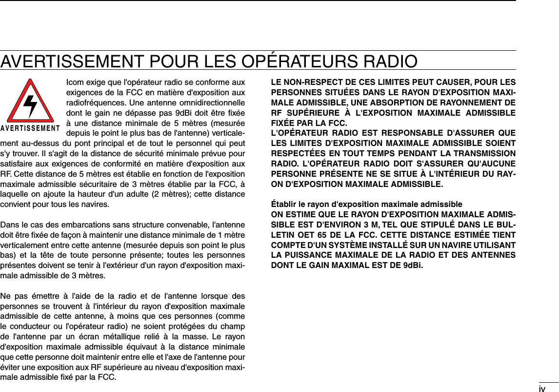
![72PANEL DESCRIPTIONSpeaker Microphone NMicrophoneSpeakerwqerq PTT SWITCH [PTT] Hold down to transmit, release to receive. (pp. 11, 12)w CHANNEL UP/DOWN KEYS [Y]/[Z] Push either key to check favorite channels, change scan-ning direction or manually resumes a scan. (pp. 11, 18)e TRANSMIT POWER KEY [HI/LO]± Push to toggle the power high or low. (p. 11) s3OMECHANNELSARESETTOONLYLOWPOWER± While holding down [HI/LO], turn ON the power to turn the Microphone Lock function ON or OFF. (p. 14)r CHANNEL 16/CALL CHANNEL KEY [16/C]± Push to select Channel 16. (p. 9)± Hold down for 1 second to select the Call channel. (p. 9) sh#!,,vAPPEARSWHENTHE#ALLCHANNELISSELECTEDSoft key function NVarious functions can be assigned to the soft keys. When a key function is assigned, the key icon is displayed above the soft key, as shown below. Consult your Icom dealer for de-tails concerning which functions are pre-programmed into the keys.Soft keys are also used for select the icon in the menu screen. (p. 91)Soft key function selection D When “ ±Ω” or “≈” is displayed beside the key icon, pushing [Ω] or [≈] sequentially shows the previous or next group of key functions that is assigned to the soft key.Push Push**Push this key to start and stop scan.The order of the key icons may differ, depending on the preprogramming.](https://usermanual.wiki/ICOM-orporated/357000/User-Guide-2220780-Page-16.png)
 to turn ON the power. q s4HREESHORTBEEPSSOUNDANDh./$3#--3)vISDISPLAYEDPush [ENT] to start the MMSI code programming. w s0USH;#,%!2=TWICETOCANCELTHEPROGRAMMINGANDGOTOTHEnormal operating screen. In this case, the transceiver cannot make a DSC call. To program the MMSI code, turn OFF the power, then turn it ON again.Enter your MMSI code in the following manner: e s3ELECTADESIREDNUMBERUSING$IALOR;∫]/[√]/[Ω]/[≈]. s0USH;%.4=OR$IALTOSETITs4OMOVETHECURSORSELECTEITHERARROWh←” or “→,” then push [ENT] or Dial.Repeat step re to enter all 9 digits. After entering the 9 digit code, “FINISH” is automatically tselected, and then push [ENT] or Dial to set it.The “MMSI CONFIRMATION” screen is displayed. yEnter your MMSI code again for confirmation. u s%NTERINTHESAMEMANNERASSTEPSe through t. When your MMSI code programming is successfully com- ipleted, the screen as shown below is briefly displayed. s!FTERTHATTHENORMALOPERATINGSCREENISDISPLAYEDThe programmed MMSI code can be checked in the MENU screen. (p. 92)](https://usermanual.wiki/ICOM-orporated/357000/User-Guide-2220780-Page-17.png)
![9BASIC OPERATION49Channel selection NChannel 16 DChannel 16 is the distress and safety channel. It is used for establishing initial contact with a station and for emergency communications. Channel 16 is automatically monitored dur-ing both Dualwatch and Tri-watch. While standing by, you must monitor Channel 16.± Push [16/C] to select Channel 16. Push [CH/WX]* to return to the screen displayed before you ±selected Channel 16, or push [∫](CH) or [√](CH) to select an operating channel.Call channel DEach regular channel group has a separate leisure use Call channel. The Call channels can be programmed, and are used to store your most often used channel in each channel group, for quick recall. The Call channel is monitored during Tri-watch. (p. 13) Hold down [16/C] for 1 second to select the Call channel of ±the selected channel group.sh#!,,vANDTHE#ALLCHANNELNUMBERAPPEARs%ACHCHANNELGROUPHASANINDEPENDENTCALLCHANNELAFTERPRO-gramming. (p. 13) Push [CH/WX]* to return to the screen displayed before you ±selected Call channel, or push [∫](CH) or [√](CH) to select an operating channel.](https://usermanual.wiki/ICOM-orporated/357000/User-Guide-2220780-Page-18.png)
![104BASIC OPERATION12345678910111213141516Channel group selection DThere are preprogrammed U.S.A. channels, International channels and Canadian channels. These channel groups may be specified for the operating area.q Push [MENU].w Rotate Dial or push [∫]/[√] to select “Radio Settings,” and then push [ENT].e Rotate Dial or push [∫]/[√] to select “CHAN Group,” and then push [ENT].r Rotate Dial or push [∫]/[√] to select the desired channel group, and then push [ENT].s53!53!)NTERNATIONAL).4AND#ANADIAN#!.CHANNELgroups can be selected.t Push [EXIT] to exit the Menu screen.y Push [∫](CH) or [√](CH) to select a channel. s0USHING;Y]/[Z] on the microphone selects only Favorite chan-nels. sh$50vAPPEARSWHENADUPLEXCHANNELISSELECTED sh!vAPPEARSWHENASIMPLEXCHANNELISSELECTEDWhen the International channel group is selected.Channel group icon appears](https://usermanual.wiki/ICOM-orporated/357000/User-Guide-2220780-Page-19.png)
![114BASIC OPERATIOND Weather channelsThe transceiver has 10 weather channels. These are used for monitoring broadcasts from NOAA (National Oceanographic and Atmospheric Administration.)The transceiver can automatically detect a weather alert tone on the selected weather channel or while scanning. (p. 16) Push [CH/WX] once or twice to select a weather channel. q sh78vAPPEARSWHENAWEATHERCHANNELISSELECTEDsh78 ” appears when the Weather Alert function is in turned ON. (p. 78)Push [ w∫](CH) or [√](CH) to select a channel. s0USHING;Y]/[Z] on the microphone selects only Favorite chan-nels.When weather alert is OFF. When weather alert is ON.Receiving and transmitting N#!54)/. Transmitting without an antenna will damage the transceiver.Hold down [PWR](Dial) to turn ON the power. q Set the audio and squelch levels. (p. 15) w First, open the squelch. Then, adjust the audio output ±level. After that, adjust the squelch level until the noise just disappears. Change the channel group. (p. 10) e Push [ r∫](CH) or [√](CH) to select a channel. (pp. 9, 10) s0USHING;Y]/[Z] on the microphone selects only Favorite chan-nels. s7HENRECEIVINGASIGNALh ” appears and audio is heard. s&URTHERADJUSTMENTOFTHEVOLUMELEVELMAYBENECESSARY Push [LO/DX] to turn the receive Attenuator function ON tor OFF, if necessary. s/NLY53!AND!USTRALIANVERSIONTRANSCEIVERS sh,/#vAPPEARSWHENTHERECEIVE!TTENUATORFUNCTIONIS/. Push [HI/LO] to select the output power, if necessary. ysh7vAPPEARSWHENHIGHPOWERISSELECTEDANDh7vAPPEARSwhen low power is selected. s#HOOSELOWPOWERFORSHORTRANGECOMMUNICATIONSCHOOSEHIGHpower for longer distance communications. s3OMECHANNELSAREFORONLYLOWPOWERu Hold down [PTT] to transmit, then speak at your normal voice level.sh ” appears. s#HANNELCANNOTBEUSEDFORTRANSMISSIONOTHERTHAN$3#](https://usermanual.wiki/ICOM-orporated/357000/User-Guide-2220780-Page-20.png)
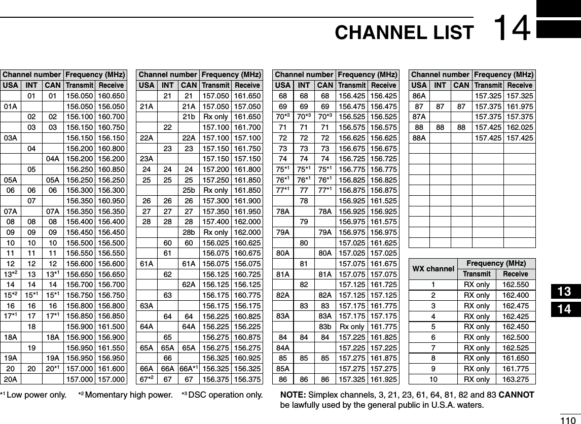
![124BASIC OPERATION2345678910111213141516i Release [PTT] to receive.Information The Noise Cancel function reduces random noise components in the transmit and/or receive signal. See page 80 for details.Simplex channels, 3, 21, 23, 61, 64, 81, 82 and 83 CANNOT be lawfully used by the general public in U.S.A. waters.)-0/24!.4 To maximize the readability of your transmit-ted signal, pause a few seconds after pushing [PTT], hold the microphone 5 to 10 cm (2 to 4 inches) from your mouth and speak at a normal voice level.NOTE for the TOT (Time-out Timer) function The TOT function inhibits continuous transmission beyond a preset time period after the transmission starts.10 seconds before transmission is cutoff, a beep sounds to indicate the transmission will be shut down and “TOT” appears in the channel name field. Transmission is not possible for 10 seconds after this shut down.MicrophoneiuryCLEARMENUENTCHCH](https://usermanual.wiki/ICOM-orporated/357000/User-Guide-2220780-Page-21.png)
![134BASIC OPERATIONCall channel programming NYou can program the Call channel with your most often-used channel in each channel group for quick recall. Select the desired channel group (INT, USA or CAN) to be qprogrammed. (p. 10)w Push [MENU].e Rotate Dial or push [Ω]/[≈] to select “Radio Settings,” and then push [ENT].r Rotate Dial or push [∫]/[√] to select “CALL CHAN,” and then push [ENT].t Rotate Dial or push [∫](CH)/[√](CH) to select a channel.y Push [ENT] to program the displayed channel as the Call channel.s0USH;#,%!2=TOCANCELChannel name programming NEach channel can be assigned a unique alphanumeric ID of up to 10 characters.Capital letters, 0 to 9, some symbols (! " # $ % & ' ( ) * + , – . ;<=>?ANDASPACECANBEINPUTPush [ q∫](CH) or [√](CH) to select a channel.s&IRSTCANCELTHE$UALWATCH4RIWATCHOR 3CAN FUNCTIONIFACTI-vated. Push [NAME] to open the channel name programming wscreen.s!BLACKBOXISDISPLAYEDONTHElRSTCHARACTEREnter the desired channel name in the following manner: e s3ELECTADESIREDCHARACTERUSING$IALOR;∫]/[√]/[Ω]/[≈]. s0USH;%.4=TOSETITs4OMOVETHECURSORSELECTEITHERARROWh←” or “→,” then push [ENT]. s3ELECTh30!#%vTHENPUSH;%.4=TOINPUTASPACE s3ELECTh$%,%4%vTHENPUSH;%.4=TODELETEACHARACTER s0USH;#,%!2=TOCANCELANDRETURNTOTHEPREVIOUSSCREEN](https://usermanual.wiki/ICOM-orporated/357000/User-Guide-2220780-Page-22.png)
![144BASIC OPERATION1234567891011121314151614Repeat step re to input all characters.t Push [Ω], [≈], [∫] or [√] to select “FINISH,” then push [ENT] to set the name and return to the previous screen.Microphone Lock function NThe Microphone Lock function electrically locks [∫], [√] and the [HI/LO] keys on the supplied microphone. This prevents accidental channel changes and function access. While holding down [HI/LO] on the microphone, hold down ±[PWR](Dial) to turn ON the transceiver and turn the Micro-phone Lock function ON or OFF.[HI/LO] [Y]/[Z]](https://usermanual.wiki/ICOM-orporated/357000/User-Guide-2220780-Page-23.png)
![154BASIC OPERATION Adjusting the display back- Nlight levelThe function display and keys can be backlit for better visibil-ity under low light conditions.The backlight is adjustable in 7 levels and OFF.Depending on the preprogramming, the adjustment method differs, as described below. Push [BKLT] to show the backlight adjustment screen. Ro- ±tate Dial to adjust the brightness of the LCD and key back-light, and then, push [ENT]. s)FNOKEYOPERATIONISPERFORMEDFORABOUTSECONDSTHETRANSCEIVERsets the selected backlight level, and returns to the normal mode. AquaQuake water draining NfunctionThe AquaQuake water draining function clears water away from the speaker grill. Without this function, water may muffle the sound coming from the speaker. A buzzing sound is heard when this function is activated.q Push [MENU].w Rotate Dial or push [Ω]/[≈] to select “AQUA QUAKE,” icon and then push the soft key below the icon. While holding down [AQUA], the AquaQuake function is ±activated to clear water away from the speaker grill.s7HILEHOLDINGDOWN;!15!=ALOWBUZZINGSOUNDSTODRAINWA-ter, regardless of the volume level setting.s4HE TRANSCEIVER KEYS EXCEPT ;$)342%33= ARE DISABLED WHILEthe AquaQuake function is activated.When the AquaQuake function is activated.](https://usermanual.wiki/ICOM-orporated/357000/User-Guide-2220780-Page-24.png)
![175SCAN OPERATIONSetting Favorite channels NFor more efficient scanning, add desired channels as Favor-ite channels, or clear the Favorite on unwanted channels. Channels that are not tagged will be skipped while scanning. Favorite channels can be independently assigned to each channel group (INT, USA, or CAN).Select the desired channel group. (p. q10)Select the desired channel to be set as a Favorite channel. wPush [ e] to set the displayed channel as a Favorite channel.sh” appears on the display.To cancel the Favorite channel setting, repeat step re.sh” disappears.Clearing (or setting) all Favorite channels Hold down [] for 3 seconds (until a long beep changes to 2 short beeps) to clear all Favorite channel settings in the selected channel group.s2EPEATABOVEPROCEDURETOSETALLCHANNELSAS&AVORITECHANNELSStarting a scan NFirst, set the scan type (Priority or Normal scan) and scan resume timer in the Menu screen. (p. 97)Select the desired channel group. (p. q10)Set the Favorite channels, as described to the left. wMake sure the squelch is closed to start a scan. ePush [SCAN] to start a Priority or Normal scan. rsh3#!.vAPPEARSDURINGA0RIORITYSCANh3#!.vAPPEARSDUR-ing a Normal scan.s7HENASIGNALISDETECTEDTHESCANPAUSESUNTILTHESIGNALDIS-appears, or resumes after pausing 5 seconds, depending on the setting. (Channel 16 is still monitored during a Priority scan.) s0USH;Y]/[Z] on either transceiver or microphone, to check the scanning Favorite channels, change the scanning direction or manually resume the scan.s!BEEPTONESOUNDSANDhvBLINKSWHENASIGNALISRECEIVEDONChannel 16 during a Priority scan.To stop the scan, push [CLEAR] or repeat step tr.Scan starts. When a signal is received.Push[SCAN];%XAMPLE= Starting a Normal scan.](https://usermanual.wiki/ICOM-orporated/357000/User-Guide-2220780-Page-26.png)
 or [Z](CH) to select the desired operating channel. Push [DW] to start a Dualwatch or Tri-watch scan. esh$5!,vAPPEARSDURING$UALWATCHh42)vAPPEARSDURINGTri-watch. s!BEEPTONESOUNDSWHENASIGNALISRECEIVEDON#HANNEL To cancel Dualwatch or Tri-watch, push [DW] again. rDUALWATCH/TRI-WATCH SIMULATIONDualwatch Tri-watchCall channelCh 88Ch 16 Ch 88 Ch 16 Ch 88 Ch 9s)FASIGNALISRECEIVEDON#HANNEL$UALWATCHAND4RIwatch pause on Channel 16 until the signal disappears.s)FASIGNALISRECEIVEDONTHE#ALLCHANNELDURING4RIWATCHTri-watch becomes Dualwatch until the signal disap-pears.s4OTRANSMITONTHESELECTEDCHANNELDURINGA$UALWATCHORTri-watch scan, hold down [PTT].;%XAMPLE= Operating Tri-watch on INT Channel 25.Tri-watch starts. Signal is received on Call channel.Tri-watch resumes after the signal disappears.Signal received on Channel 16 takes priority.](https://usermanual.wiki/ICOM-orporated/357000/User-Guide-2220780-Page-27.png)
![19DSC OPERATION7DSC address ID NProgramming Individual ID DA total of 100 DSC address IDs can be programmed and as-signed a name of up to 10 characters.Enter “INDIVIDUAL ID” in the DSC SETTINGS menu. qPush [ADD]. w s4HEh).$)6)$5!,)$vPROGRAMSCREENISDISPLAYEDEnter a desired individual ID in the following way: e s3ELECTADESIREDNUMBERUSING;Y]/[Z]/[Ω]/[≈]. s0USH;%.4=TOSETITs4OMOVETHECURSORROTATEDIALORSELECTEITHERARROWh←” or “→,” then push [ENT]. The first digit is specified as ‘0’ for a Group ID. The first two digits are ‘0’ for any Coast station ID.r Repeat step e to enter all 9 digits.t After entering the 9 digit code, push [ENT] or Dial to set it. s4HE)$NAMEPROGRAMMINGSCREENISDISPLAYEDy Enter a desired 10 digit ID name in the following way: s3ELECTADESIREDCHARACTERUSING;Y]/[Z]/[Ω]/[≈]. s0USH;%.4=TOSETITs4OMOVETHECURSORROTATEDIALOR select either arrow, “←” or “→,” then push [ENT]. s0USH;=THEN;=THEN;!"#=TOSELECTACHARACTERGROUPu After entering the ID name, select “FINISH” using [Y]/[Z]/[Ω]/[≈], then push [ENT] to program it. s4HEh).$)6)$5!,)$vLISTSCREENISDISPLAYEDi Push [MENU] to exit the MENU screen. eMENUf ¶ eDSC SETf ¶ eIndividual IDf (Push [MENU]) (Select icon) (Rotate Dial, then push [ENT].)](https://usermanual.wiki/ICOM-orporated/357000/User-Guide-2220780-Page-28.png)
![207DSC OPERATION12345678910111213141516D Programming Group IDEnter “GROUP ID” in the DSC SETTINGS menu. qPush [ADD]. w s4HEh'2/50)$vPROGRAMSCREENISDISPLAYEDe Enter a desired group ID in the following way: s3ELECTADESIREDNUMBERUSING;Y]/[Z]/[Ω]/[≈]. s0USH;%.4=TOSETITs4OMOVETHECURSORROTATEDIALORSELECTEITHERARROWh←” or “→,” then push [ENT]. The first digit is fixed as ‘0’ for a Group ID.The first two digits are ‘0’ for any Coast station ID.r Repeat step e to input the specific 9 digits group code.t After entering the 9 digit code, push [ENT] or Dial to set it. s4HE'ROUP)$NAMEPROGRAMMINGSCREENISDISPLAYEDEnter a desired 10 digit ID name in the following way: y s3ELECTADESIREDCHARACTERUSING;Y]/[Z]/[Ω]/[≈]. s0USH;%.4=TOSETITs4OMOVETHECURSORROTATEDIALOR select either arrow, “←” or “→,” then push [ENT]. s0USH;=THEN;=THEN;!"#=TOSELECTACHARACTERGROUP After entering the ID name, select “FINISH” using dial or u[Y]/[Z]/[Ω]/[≈], then push [ENT] or Dial to program it. s4HEh'2/50)$vLISTSCREENISDISPLAYEDi Push [MENU] to exit the MENU screen. eMENUf ¶ eDSC SETf ¶ eGroup IDf (Push [MENU]) (Select icon) (Rotate Dial, then push [ENT].)](https://usermanual.wiki/ICOM-orporated/357000/User-Guide-2220780-Page-29.png)
![217DSC OPERATIOND Deleting Individual/Group IDq Enter “INDIVIDUAL ID” or “GROUP ID” in the DSC SET-TINGS menu.s7HENNOADDRESS)$ISPROGRAMMEDh.O)$vISDISPLAYED)NTHIScase, push [MENU] to exit the MENU screen.w Rotate Dial or push [Y]/[Z] to select a desired ID name, then push [DEL].e Push [OK] to delete the ID, and return to the “INDIVIDUAL ID” or “GROUP ID” list screen. s0USH;#!.#%,=TOCANCELITr Push [MENU] to exit the MENU screen. eMENUf ¶ eDSC SETf ¶ eIndividual IDf/eGroup IDf(Push [MENU]) (Select icon) (Rotate Dial, then push [ENT].)](https://usermanual.wiki/ICOM-orporated/357000/User-Guide-2220780-Page-30.png)
![227DSC OPERATION12345678910111213141516A Distress call should include the ship’s position and time. If no GPS is connected, your position and UTC (Universal Time Coordinated) time should be manually input. They are automatically included when a GPS receiver compatible with the NMEA0183 ver. 2.0 or 3.01 or NMEA 2000 format is con-nected.s-ANUALPROGRAMMINGISDISABLEDWHENA'03RECEIVERISconnected.s-ANUALLYPROGRAMMEDPOSITIONANDTIMEWILLBEHELDFORonly 23.5 hours.q Enter “POSITION INPUT” in the DSC SETTINGS menu. Edit your latitude and longitude position using Dial, or [ wY]/[Z]/[Ω]/[≈]. s3ELECTADESIREDNUMBERUSING;Y]/[Z]/[Ω]/[≈]. s0USH;%.4=TOSETITs4OMOVETHECURSORROTATEDIALORSELECTEITHERARROWh←” or “→,” then push [ENT]. s3ELECT..ORTHLATITUDEOR33OUTHLATITUDEWHENTHECURSORISon the ‘N’ or ‘S’ position. s3ELECT77ESTLONGITUDEOR%%ASTLONGITUDEWHENTHECURSORis on the ‘W’ or ‘E’ position.After entering the position, push [ENT] to program it. e The UTC time programming screen is displayed, enter the rUTC time in the following way: s3ELECTADESIREDNUMBERUSING;Y]/[Z]/[Ω]/[≈]. s0USH;%.4=TOSETITs4OMOVETHECURSORROTATEDIALORSELECTEITHERARROWh←” or “→,” then push [ENT]. Push [ENT] or Dial to program your position and time. t s2ETURNTOTHEh$3#3%44).'3vSCREENPosition and time programming N eMENUf ¶ eDSC SETf ¶ ePosition Inputf (Push [MENU]) (Select icon) (Rotate Dial, then push [ENT].)](https://usermanual.wiki/ICOM-orporated/357000/User-Guide-2220780-Page-31.png)
![237DSC OPERATIONDistress call NA Distress call should be transmitted if, in the opinion of the Master, the ship or a person is in distress and requires im-mediate assistance.NEVER MAKE A DISTRESS CALL IF YOUR SHIP OR A PERSON IS NOT IN AN EMERGENCY. A DISTRESS CALL SHOULD BE MADE ONLY WHEN IMMEDIATE HELP IS NEEDED.Simple call DConfirm no Distress call is being received. q While lifting up the key cover, hold down [DISTRESS] for 3 wseconds to transmit the Distress call.s7HILEHOLDINGDOWN;$)342%33=COUNTDOWNBEEPSSOUNDANDboth the key and display backlighting blink. s$3# CHANNEL #HANNEL IS AUTOMATICALLY SELECTED AND THEDistress call is transmitted. After transmitting the call, the transceiver waits for an ac- eknowledgment call.s4HE $ISTRESS CALL IS AUTOMATICALLY TRANSMITTED EVERY TO minutes, until an acknowledgement is received (‘Call repeat’ mode), or DSC Cancel call is made. (p. 27) s0USH;2%3%.$=TOMANUALLYTRANSMITTHE$ISTRESSREPEATCALL s0USH ;Ω]/[≈] then push [INFO] to display the transmitted Dis-tress call information. s0USH;Ω]/[≈] then push [PAUSE] to pause the ‘Call repeat’ mode, push [RESUME COUNTDOWN] to resume it. After receiving the acknowledgment, push [ALARM OFF] rthen reply using the microphone.A distress alert default contains: ± s.ATUREOFDISTRESS 5NDESIGNATEDDISTRESS s0OSITIONINFORMATION4HE LATEST '03 OR MANUAL INPUT POSITIONis held for 23.5 hours, or until the power is turned OFF.](https://usermanual.wiki/ICOM-orporated/357000/User-Guide-2220780-Page-32.png)
![247DSC OPERATION12345678910111213141516D Regular callThe nature of the Distress call should be included in the Dis-tress call.Enter “DISTRESS CALL” in the DSC menu. qw Select the nature of the distress using Dial or [Y]/[Z], then push Dial or [ENT].s@5NDESIGNATED@&IRE%XPLOSION@&LOODING@#OLLISION@'ROUNDING‘Capsizing,’ ‘Sinking,’ ‘Adrift,’ ‘Abandoning ship,’ ‘Piracy’ or ‘Man Overboard’ is selectable.s4HENATUREOFTHEDISTRESSISSTOREDFORMINUTESAFTERASELEC-tion is made.e The Distress call confirmation screen is displayed.s2OTATE$IALORPUSH;Y]/[Z] to see the hidden lines.r Hold down [DISTRESS] for 3 seconds to transmit the Dis-tress call.s7HILEHOLDINGDOWN;$)342%33=COUNTDOWNBEEPSSOUNDANDboth the key and display backlighting blink. s4HESELECTEDNATUREOFTHEDISTRESSISSTOREDFORMINUTES eMENUf ¶ eDSCf ¶ eDistress Callf(Push [MENU]) (Select icon) (Rotate Dial, then push [ENT].)](https://usermanual.wiki/ICOM-orporated/357000/User-Guide-2220780-Page-33.png)
![257DSC OPERATIONt After transmitting the call, the transceiver waits for an ac-knowledgment call.s4HE $ISTRESS CALL IS AUTOMATICALLY TRANSMITTED EVERY TO minutes, until an acknowledgement is received (‘Call repeat’ mode), or DSC cancel call is made. (p. 27) s0USH;2%3%.$=TOMANUALLYTRANSMITTHE$ISTRESSREPEATCALL s0USH ;Ω]/[≈] then push [INFO] to display the transmitted Dis-tress call information. s0USH;Ω]/[≈] then push [PAUSE] to pause the ‘Call repeat’ mode, push [RESUME COUNTDOWN] to resume it.y After receiving an acknowledgment call, push [ALARM OFF] then reply using the microphone.± A distress alert contains: s.ATUREOFDISTRESS 3ELECTEDINSTEPw. s0OSITIONINFORMATION4HE LATEST '03 OR MANUAL INPUT POSITIONis held for 23.5 hours, or until the power is turny After receiving an acknowledgment call, push [ALARM OFF] then reply using the microphone.± A distress alert contains: s.ATUREOFDISTRESS 3ELECTEDINSTEPw. s0OSITIONINFORMATION4HE LATEST '03 OR MANUAL INPUT POSITIONis held for 23.5 hours, or until the power is turned OFF.](https://usermanual.wiki/ICOM-orporated/357000/User-Guide-2220780-Page-34.png)
![267DSC OPERATION12345678910111213141516When no GPS receiver is connected, and both position and time have been manually programmed, the screen as shown below appears. Edit your latitude and longitude position and UTC time as follows: Push [CHG], then edit your latitude and longitude position ±and UTC time. s3ELECTADESIREDNUMBERUSING;Y]/[Z]/[Ω]/[≈]. s0USH;%.4=OR$IALTOSETITs4OMOVETHECURSORSELECTEITHERARROWh←” or “→,” then push [ENT] or Dial. s3ELECT..ORTHLATITUDEOR33OUTHLATITUDEWHENTHECURSORISon the ‘N’ or ‘S’ position. s3ELECT77ESTLONGITUDEOR%%ASTLONGITUDEWHENTHECURSORis on the ‘W’ or ‘E’ position.](https://usermanual.wiki/ICOM-orporated/357000/User-Guide-2220780-Page-35.png)
![277DSC OPERATIOND Distress cancel call While waiting for an acknowledgment call, push [CAN- qCEL].Push [CONTINUE]. w s0USH;"!#+=TORETURNTOWAITINGFORANACKNOWLEDGEMENTCALLe Push [FINISH]. s0USH;%8)4=TORETURNTOWAITINGFORANACKNOWLEDGEMENTCALLr The Distress cancel call is transmitted.t Channel 16 is automatically selected. s2EPORTYOURSITUATIONUSINGTHEMICROPHONE s!FTERTHEREPORTPUSH ;%8)4=TORETURNTO THENORMALOPERATINGmode.](https://usermanual.wiki/ICOM-orporated/357000/User-Guide-2220780-Page-36.png)
![287CHAPTER CONTINUED12345678910111213141516Transmitting DSC calls NTo ensure correct operation of the DSC function, make sure you correctly set the CH70 SQL Level. (p. 71)Transmitting an individual call DThe Individual call function allows you to transmit a DSC sig-nal to only a specific station.Enter “INDIVIDUAL CALL” in the DSC CALLS menu. q eMENUf ¶ eDSCf ¶ eIndividual Callf(Push [MENU]) (Select icon) (Rotate Dial, then push [ENT].) Select the desired pre-programmed individual address, or w“Manual Input,” using Dial or [Y]/[Z], then push [ENT]. s4HE)$CODEFORTHE)NDIVIDUALCALLCANBESETlRSTPs7HENh-ANUAL)NPUTvISSELECTEDSETADESIREDDIGIT--3))$code for the individual you wish to call. About Manual Inputting:Enter a desired individual ID in the following way:s3ELECTADESIREDNUMBERUSING;Y]/[Z]/[Ω]/[≈].s0USH;%.4=TOSETITs4OMOVETHECURSORROTATEDIALOR select either arrow, “←” or “→,” then push [ENT].s4HElRSTDIGITISSPECIlEDAS@FORA'ROUP)$)FA'ROUP)$ISentered, an error beep sounds after pushing [FINISH].s4HElRSTTWODIGITSARE@FORANYCOASTSTATION)$./4% When a coast station is selected in step w, the voice channel is automatically specified by the coast sta-tion. Therefore, skip step r and go directly to step t.](https://usermanual.wiki/ICOM-orporated/357000/User-Guide-2220780-Page-37.png)
/[Z](CH), then push [ENT]. s)NTERSHIPCHANNELSAREALREADYPRESETINTOTHETRANSCEIVERINTHErecommended order.r A confirmation screen appears. s#ONlRMTHECALLCONTENTSt Push [CALL] to transmit the Individual call. s)F#HANNELISBUSYTHETRANSCEIVERSTANDSBYUNTILTHECHANNELbecomes clear.y Standby on Channel 70 until an acknowledgement is re-ceived.i When the acknowledgement ‘Able to comply’ is received, beeps sound and the screen below is displayed.](https://usermanual.wiki/ICOM-orporated/357000/User-Guide-2220780-Page-38.png)
![307CHAPTER CONTINUED12345678910111213141516 Push [ALARM OFF] to stop the beeps and then select the intership channel specified in step r. s!DIFFERENTINTERSHIPCHANNELWILLBESELECTEDIF THE STATION YOUcalled cannot use the channel. s2EPLYUSINGTHEMICROPHONE!NDGOTOSTEPo. Or, when the acknowledgement ‘Unable to comply’ is re-ceived, beeps sound and the screen below is displayed. Push [ALARM OFF] to stop the beeps. Then push [EXIT] to return to the operating channel (before you entered the MENU screen). After communicating, push [EXIT] to return to the normal ooperating mode.Convenient! When the optional MA-500TR CLASS B AIS TRANSPONDER is connected to your transceiver, you can transmit individual DSC calls to selected AIS targets on the transponder without needing to enter the target’s MMSI code.See pages 70 and 84 for more details.](https://usermanual.wiki/ICOM-orporated/357000/User-Guide-2220780-Page-39.png)
![317DSC OPERATIONTransmitting an Individual Acknowledgement DWhen receiving an Individual call, you can transmit an ac-knowledgement (‘Able to Comply,’ ‘Propose New Channel’ or ‘Unable to Comply’) by using the on-screen prompts (Quick ACK.) Also, you can send an acknowledgement through the MENU system (Man ual ACK.)Quick ACK: When an Individual call is received, beeps sound and the qscreen below is displayed. Push [ALARM OFF] to stop the beeps.Push [ACK]. w Select one of three options, then push [ENT]. e s!BLETO#OMPLY -AKEANACKNOWLEDGMENTCALLWITHOUTany changes. s5NABLETO#OMPLY 9OUCANNOTMAKEACOMMUNICATION The Acknowledgement call (‘Unable to Comply’) can be automatically trans-mitted, if set. See page 66 for details. s0ROPOSE.EW#HANNEL 9OU CAN MAKE AN ACKNOWLEDGEMENTcall, but you specify the intership chan-nel. Select a desired intership channel, using dial, or [Y](CH)/[Z](CH), then push [ENT].](https://usermanual.wiki/ICOM-orporated/357000/User-Guide-2220780-Page-40.png)
![327CHAPTER CONTINUED12345678910111213141516The Individual ACK confirmation screen is displayed. r Push [CALL] to transmit an acknowledgement call.The screens shown below are displayed. tReply to the call using the microphone. yPush [EXIT] to return to the normal operating mode. uManual ACK:Enter “INDIVIDUAL ACK” in the DSC CALLS menu. q eMENUf ¶ eDSCf ¶ eIndividual ACKf(Push [MENU]) (Select icon) (Rotate Dial, then push [ENT].)s7HENNO)NDIVIDUALCALLHASBEENRECEIVEDh)NDIVIDUAL!#+vITEMwill not be displayed. Select a desired individual address or ID code to reply to, wusing Dial or [Y]/[Z], then push [ENT]. Perform steps ee to u, as described in “Quick ACK:,” be-ginning on the previous page.](https://usermanual.wiki/ICOM-orporated/357000/User-Guide-2220780-Page-41.png)
![337DSC OPERATIONTransmitting a Group call DThe Group call function allows you to transmit a DSC signal to only a specific group.Enter “GROUP CALL” in the DSC CALLS menu. q eMENUf ¶ eDSCf ¶ eGroup Callf(Push [MENU]) (Select icon) (Rotate Dial, then push [ENT].) Select the desired pre-programmed group address or w“Manual Input,” using Dial or [Y]/[Z], then push [ENT]. s4HE)$CODEFORTHE'ROUPCALLCANBESETlRSTPs7HENh-ANUAL)NPUTvISSELECTEDSETTHEDIGIT)$CODEFORTHEgroup you wish to call.e Select a desired intership channel using Dial or [Y](CH)/[Z](CH), then push [ENT]. s)NTERSHIPCHANNELSAREALREADYPRESETINTOTHETRANSCEIVERINTHErecommended order. About Manual Inputting:Enter a desired group ID in the following way:s3ELECTADESIREDNUMBERUSING;Y]/[Z]/[Ω]/[≈].s0USH;%.4=OR$IALTOSETITs4OMOVETHECURSORROTATEDIALOR select either arrow, “←” or “→,” then push [ENT].s4HElRSTDIGITISSPECIlEDAS@FORA'ROUP)$s4HElRSTTWODIGITSARE@FORANY#OASTSTATION)$](https://usermanual.wiki/ICOM-orporated/357000/User-Guide-2220780-Page-42.png)
![347DSC OPERATION12345678910111213141516r A confirmation screen appears. s#ONlRMTHECALLCONTENTS Push [CALL] to transmit the Group call. t s)F#HANNELISBUSYTHETRANSCEIVERSTANDSBYUNTILTHECHANNELbecomes clear. After the Group call has been transmitted, the following yscreen is displayed.Announce the information using the microphone. u After the announcement, push [EXIT] to return to the nor- imal operating mode.](https://usermanual.wiki/ICOM-orporated/357000/User-Guide-2220780-Page-43.png)
![357DSC OPERATIONTransmitting an All Ships call DAll ships, that have DSC transceiver, use Channel 70 as their ‘listening channel.’ When you want to announce a message to these ships within range, use the ‘All Ships Call’ function.Enter “ALL SHIPS CALL” in the DSC CALLS menu. q eMENUf ¶ eDSCf ¶ eAll Ships Callf(Push [MENU]) (Select icon) (Rotate Dial, then push [ENT].) Select a desired category, using Dial or [ wY]/[Z], then push [ENT].s4HE SELECTABLE CATEGORY MAY DIFFER DEPENDING ON THE PRO-grammed setting. Ask your dealer for the selectable categories. Select a desired traffic channel, using Dial or [ eY]/[Z], then push [ENT]. s4HESELECTEDCHANNELISDISPLAYEDr A confirmation screen appears. s#ONlRMTHECALLCONTENTS](https://usermanual.wiki/ICOM-orporated/357000/User-Guide-2220780-Page-44.png)
![367DSC OPERATION12345678910111213141516t Push [CALL] to transmit the All Ships call. s)F#HANNELISBUSYTHETRANSCEIVERSTANDSBYUNTILTHECHANNELbecomes clear. After the All Ships call has been transmitted, the following yscreen is displayed.Announce the message using the microphone. u After the announcement, push [EXIT] to return to the nor- imal operating mode.](https://usermanual.wiki/ICOM-orporated/357000/User-Guide-2220780-Page-45.png)
![377DSC OPERATIOND Transmitting a Position Request Call (U.S.A. and Australian version transceiver only)Transmit a Position Request Call when you want to know a specific ship’s current position, etc.Enter “POSITION REQUEST” in the DSC CALLS menu. q eMENUf ¶ eDSCf ¶ ePosition Requestf(Push [MENU]) (Select icon) (Rotate Dial, then push [ENT].) Select the desired pre-programmed individual address, or w“Manual Input,” using Dial or [Y]/[Z], then push [ENT].s4HE)$CODEFORTHE0OSITION2EQUEST#ALLCANBESETlRSTPs7HENh-ANUAL)NPUTvISSELECTEDSETADESIREDDIGIT--3))$code for the individual you wish to call.About Manual Inputting:Enter a desired individual ID in the following way:s3ELECTADESIREDNUMBERUSING$IALOR;Y]/[Z]/[Ω]/[≈].s0USH;%.4=OR$IALTOSETITs4OMOVETHECURSORSELECTEITHERARROWh←” or “→,” then push [ENT] or Dial.s4HElRSTDIGITISSPECIlEDAS@FORA'ROUP)$)FA'ROUP)$ISentered, an error beep sounds after pushing [FINISH].s4HElRSTTWODIGITSARE@FORANYCOASTSTATION)$e A confirmation screen appears. s#ONlRMTHECALLCONTENTS](https://usermanual.wiki/ICOM-orporated/357000/User-Guide-2220780-Page-46.png)
![387DSC OPERATION12345678910111213141516Push [CALL] to transmit the Position Request Call. r s)F#HANNELISBUSYTHETRANSCEIVERSTANDSBYUNTILTHECHANNELbecomes clear. After the Position Request Call has been transmitted, the tfollowing screen is displayed. When the acknowledgement call is received, beeps sound yand the following screen is displayed.u Push [ALARM OFF] to stop the beeps, and then the screen as shown below is displayed.Push [EXIT] to return to the normal operating mode. i](https://usermanual.wiki/ICOM-orporated/357000/User-Guide-2220780-Page-47.png)
![397DSC OPERATIOND Transmitting a Position Report CallTransmit a Position Report Call when you want to announce your own position to a specific ship and receive an answer back.Enter “POSITION REPORT” in the DSC CALLS menu. q eMENUf ¶ eDSCf ¶ ePosition Reportf(Push [MENU]) (Select icon) (Rotate Dial, then push [ENT].) Select the desired pre-programmed individual address, or w“Manual Input,” using Dial or [Y]/[Z], then push [ENT]. s4HE)$CODEFORTHE)NDIVIDUALCALLCANBESETlRSTPs7HENh-ANUAL)NPUTvISSELECTEDSETADESIREDDIGIT--3))$code for the individual you wish to call. About Manual Inputting:Enter a desired individual ID in the following way:s3ELECTADESIREDNUMBERUSING$IALOR;Y]/[Z]/[Ω]/[≈].s0USH;%.4=ORTOSETITs4OMOVETHECURSORSELECTEITHERARROWh←” or “→,” then push [ENT] or Dial.s4HElRSTDIGITISSPECIlEDAS@FORA'ROUP)$)FA'ROUP)$ISentered, an error beep sounds after pushing [FINISH].s4HElRSTTWODIGITSARE@FORANYCOASTSTATION)$A confirmation screen appears. e s#ONlRMTHECALLCONTENTS](https://usermanual.wiki/ICOM-orporated/357000/User-Guide-2220780-Page-48.png)
![407DSC OPERATION12345678910111213141516Push [CALL] to transmit the Position Report Call. r s)F#HANNELISBUSYTHETRANSCEIVERSTANDSBYUNTILTHECHANNELbecomes clear. After the Position Report Call has been transmitted, the ttransceiver automatically returns to the normal operating mode.When no GPS receiver is connected, and both position and time have been manually programmed, the screen shown below appears. Edit your latitude and longitude position and UTC time as follows: Push [CHG], then edit your latitude and longitude position ±and UTC time. s3ELECTADESIREDNUMBERUSING$IALOR;Y]/[Z]/[Ω]/[≈]. s0USH;%.4=OR$IALTOSETITs4OMOVETHECURSORSELECTEITHERARROWh←” or “→,” then push [ENT] or Dial. s3ELECT..ORTHLATITUDEOR33OUTHLATITUDEWHENTHECURSORis on the ‘N’ or ‘S’ position. s3ELECT77ESTLONGITUDEOR%%ASTLONGITUDEWHENTHECUR-sor is on the ‘W’ or ‘E’ position.](https://usermanual.wiki/ICOM-orporated/357000/User-Guide-2220780-Page-49.png)
![417DSC OPERATIONTransmitting a Polling Request Call DTransmit a Polling Request Call when you want to know a specific vessel is in the communication area, or not.Enter “POLLING REQUEST” in the DSC CALLS menu. q eMENUf ¶ eDSCf ¶ ePolling Requestf(Push [MENU]) (Select icon) (Rotate Dial, then push [ENT].) Select the desired pre-programmed individual address, or w“Manual Input,” using Dial or [Y]/[Z], then push [ENT]. s4HE)$CODEFORTHE)NDIVIDUALCALLCANBESETlRSTPs7HENh-ANUAL)NPUTvISSELECTEDSETADESIREDDIGIT--3))$code for the individual you wish to call. About Manual Inputting:Enter a desired individual ID in the following way:s3ELECTADESIREDNUMBERUSING$IALOR;Y]/[Z]/[Ω]/[≈].s0USH;%.4=TOSETITs4OMOVETHECURSORSELECTEITHERARROWh←” or “→,” then push [ENT] or Dial.s4HElRSTDIGITISSPECIlEDAS@FORA'ROUP)$)FA'ROUP)$ISentered, an error beep sounds after pushing [FINISH].s4HElRSTTWODIGITSARE@FORANYCOASTSTATION)$A confirmation screen appears. e s#ONlRMTHECALLCONTENTS](https://usermanual.wiki/ICOM-orporated/357000/User-Guide-2220780-Page-50.png)
![427DSC OPERATION12345678910111213141516Push [CALL] to transmit the Polling Request Call. r s)F#HANNELISBUSYTHETRANSCEIVERSTANDSBYUNTILTHECHANNELbecomes clear. After the Polling Request Call has been transmitted, the tfollowing screen is displayed. When the acknowledgement call is received, beeps sound yand the following screen is displayed. Push [ALARM OFF] to stop the beeps, and then the screen uas shown below is displayed.Push [EXIT] to return to the normal operating mode. i](https://usermanual.wiki/ICOM-orporated/357000/User-Guide-2220780-Page-51.png)
![437DSC OPERATIOND Transmitting a Test callTesting on the exclusive DSC distress and safety calling chan-nels should be avoided as much as possible. When testing on a distress/safety channel is unavoidable, you should indicate that these are test transmissions. Normally the test call would require no further communica-tions between the two stations involved.Enter “TEST CALL” in the DSC CALLS menu. q eMENUf ¶ eDSCf ¶ eTest Callf(Push [MENU]) (Select icon) (Rotate Dial, then push [ENT].) Select a desired pre-programmed individual address, or w“Manual Input,” then push Dial or [ENT]. s4HE)$CODEFORTHE)NDIVIDUALCALLCANBESETlRSTPs7HENh-ANUAL)NPUTvISSELECTEDSETTHEDIGIT--3))$CODEFORthe individual you wish to call.About Manual Inputting:Enter a desired address ID in the following way:s3ELECTADESIREDNUMBERUSING$IALOR;Y]/[Z]/[Ω]/[≈].s0USH;%.4=OR$IALTOSETITs4OMOVETHECURSORSELECTEITHERARROWh←” or “→,” then push [ENT] or Dial.s4HElRSTDIGITISSPECIlEDAS@FORA'ROUP)$)FA'ROUP)$ISentered, an error beep sounds after pushing [FINISH].s4HElRSTTWODIGITSARE@FORANY#OASTSTATION)$e A confirmation screen appears. s#ONlRMTHECALLCONTENTS](https://usermanual.wiki/ICOM-orporated/357000/User-Guide-2220780-Page-52.png)
![447DSC OPERATION12345678910111213141516Push [CALL] to transmit the Test call. r s)F#HANNELISBUSYTHETRANSCEIVERSTANDSBYUNTILTHECHANNELbecomes clear. After the Test call has been transmitted, the following tscreen is displayed.y When the acknowledgement call is received, beeps sound and the following screen is displayed. Push [ALARM OFF] to stop the beeps, and then the screen uas shown below is displayed.i Push [EXIT] to return to the normal operating mode.](https://usermanual.wiki/ICOM-orporated/357000/User-Guide-2220780-Page-53.png)
![457DSC OPERATIOND Transmitting a Test Acknowledgement callWhen the “TEST ACK” in DSC settings is set to ‘Auto’ (p. 68), the transceiver automatically transmits a reply call when receiving a Test call.Quick ACK: When a Test call is received, beeps sound and the screen qshown below is displayed. Push [ALARM OFF] to stop the beeps.Push [ACK]. w s0USH;).&/=TODISPLAYTHE4ESTCALLINFORMATION Push [BACK] to return to the previous screen, or push [ACK].The Test ACK confirmation screen is displayed. e Push [CALL] to transmit the acknowledgement call.r While transmitting the acknowledgement call, the screen shown below is displayed, and then returns to the normal operating mode.](https://usermanual.wiki/ICOM-orporated/357000/User-Guide-2220780-Page-54.png)
![467DSC OPERATION12345678910111213141516Manual ACK:Enter “TEST ACK” in the DSC CALLS menu. q eMENUf ¶ eDSCf ¶ eTest ACKf (Push [MENU]) (Select icon) (Rotate Dial, then push [ENT].) s)FNO4ESTCALLHASBEENRECEIVEDTHEh4%34!#+vITEMWILLNOTbe displayed.w Select a desired Test call to reply to, using Dial or [Y]/[Z], then push [ENT].e The Test ACK confirmation screen is displayed. Push [CALL] to transmit the acknowledgement call.r While transmitting the acknowledgement call, the screen shown below is displayed, and then returns to the normal operating mode.](https://usermanual.wiki/ICOM-orporated/357000/User-Guide-2220780-Page-55.png)
![477DSC OPERATIONTransmitting a Position Reply call DTransmit a Position Reply call when a Position Request call is received.When the “POSITION ACK” in DSC Settings is set to ‘Auto’ (p. 68), the transceiver automatically transmits a reply call when receiving a Position Request call.Quick Reply: When a Position Request call is received, beeps sound qand the screen shown below is displayed. Push [ALARM OFF] to stop the beeps.w Push [ACK]. s0USH;).&/=TODISPLAYTHE0OSITION2EQUESTCALLINFORMATION Push [BACK] to return to the previous screen, or push [ACK].The Position Reply confirmation screen is displayed. e Push [CALL] to transmit the reply call. While transmitting the reply call, the screen shown below ris displayed, and then returns to the normal operating mode.](https://usermanual.wiki/ICOM-orporated/357000/User-Guide-2220780-Page-56.png)
![487DSC OPERATION12345678910111213141516Manual Reply:Enter “POSITION REPLY” in the DSC CALLS menu. q eMENUf ¶ eDSCf ¶ ePosition Replyf (Push [MENU]) (Select icon) (Rotate Dial, then push [ENT].) s)FNO0OSITION2EQUESTCALLHASBEENRECEIVEDTHEh0/3)4)/.REPLY” item will not be displayed. Select a desired Position Request call to reply to, using wDial or [Y]/[Z], then push [ENT].e The Position Reply call confirmation screen is displayed. Push [CALL] to transmit the acknowledgement call.r While transmitting the reply call, the screen shown below is displayed, and then returns to the normal operating mode.When no GPS receiver is connected, and both position and time have been manually programmed, the screen shown below appears. Edit your latitude and longitude position and UTC time as follows: Push [CHG], then edit your latitude and longitude position ±and UTC time. s3ELECTADESIREDNUMBERUSING$IALOR;Y]/[Z]/[Ω]/[≈]. s0USH;%.4=OR$IALTOSETITs4OMOVETHECURSORSELECTEITHERARROWh←” or “→,” then push [ENT] or Dial. s3ELECT..ORTHLATITUDEOR33OUTHLATITUDEWHENTHECURSORis on the ‘N’ or ‘S’ position. s3ELECT77ESTLONGITUDEOR%%ASTLONGITUDEWHENTHECUR-sor is on the ‘W’ or ‘E’ position.](https://usermanual.wiki/ICOM-orporated/357000/User-Guide-2220780-Page-57.png)
![497DSC OPERATIOND Transmitting a Position Report Reply callTransmit a Position Report Reply call when a Position Report call is received.Quick Reply: When a Position Report call is received, beeps sound and qthe screen as shown below is displayed. Push [ALARM OFF] to stop the beeps. s0USH;).&/=TODISPLAYTHE0OSITION2EPORT2EQUESTCALLINFORMA-tion. Push [BACK] to return to the previous screen.](https://usermanual.wiki/ICOM-orporated/357000/User-Guide-2220780-Page-58.png)
![507DSC OPERATION12345678910111213141516Manual Reply: Enter “POSITION REPORT REPLY” in the DSC CALLS qmenu. eMENUf ¶ eDSCf ¶ ePosition Report Replyf (Push [MENU]) (Select icon) (Rotate Dial, then push [ENT].) s)FNO0OSITION2EPORT2EQUESTCALLHASBEENRECEIVEDTHEh0/3)-TION REPORT REPLY” item will not be displayed. Select a desired Position Report Request call to reply to, wusing Dial or [Y]/[Z], then push [ENT]. The Position Report Reply call confirmation screen is dis- eplayed. Push [CALL] to transmit the acknowledgement call. While transmitting the reply call, the screen shown below ris displayed, and then returns to the normal operating mode.](https://usermanual.wiki/ICOM-orporated/357000/User-Guide-2220780-Page-59.png)
![517DSC OPERATIONTransmitting a Polling Reply call DTransmit a Polling Reply call when a Polling Request call is received.When the “POSITION ACK” in DSC Settings is set to ‘Auto’ (p. 66), the transceiver automatically transmits a reply call when receiving a Polling Request call.Quick Reply: When a Polling Request call is received, beeps sound and qthe screen as shown below is displayed. Push [ALARM OFF] to stop the beeps.Push [ACK]. w s0USH;).&/=TODISPLAYTHE0OLLING2EQUESTCALLINFORMATION Push [BACK] to return to the previous screen, or push [ACK].The Polling Reply confirmation screen is displayed. e Push [CALL] to transmit the reply call. While transmitting the reply call, the screen shown below ris displayed, and then returns to the normal operating mode.](https://usermanual.wiki/ICOM-orporated/357000/User-Guide-2220780-Page-60.png)
![527DSC OPERATION12345678910111213141516Manual Reply:Enter “POLLING REPLY” in the DSC CALLS menu. q eMENUf ¶ eDSCf ¶ ePolling Replyf (Push [MENU]) (Select icon) (Rotate Dial, then push [ENT].) s)FNO0OLLING2EQUESTCALLHASBEENRECEIVEDTHEh0/,,).'2%-PLY” item will not be displayed. Select a desired Polling Request call to be replied, using wDial or [Y]/[Z], then push [ENT].e The Polling Reply call confirmation screen is displayed. Push [CALL] to transmit the acknowledgement call.r While transmitting the reply call, the screen shown below is displayed, and then returns to the normal operating mode.](https://usermanual.wiki/ICOM-orporated/357000/User-Guide-2220780-Page-61.png)
![537DSC OPERATIONReceiving DSC calls NReceiving a Distress Call DWhen a Distress Call is received:The emergency alarm sounds for 2 minutes. ±“ RCVD DISTRESS” pops up and the LCD backlight ±blinks.q Push [ALARM OFF] to stop the alarm and the blinking backlight.w Push a soft key to select your desired action. [IGN] ±Push to return to the normal operating mode. s4HETRANSCEIVEREXITSTHE$3#MODE s"YPUSHING;044=THETRANSCEIVERALSOEXITSTHE$3#MODE sh ” continues to blink and the Call is stored in the Received Call Log. [INFO] ±Push to display the Received call information. (p. 65) [ACPT] Push to accept the call. ± And then, push [CH 16] to switch the operating channel to Channel 16, and then monitor it, as a coast station may require assistance. s)FYOUHAVENTPUSHED;#(=WITHINSECONDSTHEOPERAT-ing channel automatically switches to Channel 16. (p. 69)Push](https://usermanual.wiki/ICOM-orporated/357000/User-Guide-2220780-Page-62.png)
![547DSC OPERATION12345678910111213141516Receiving a Distress Acknowledgement DWhen a Distress Acknowledgement sent to another ship is received:The emergency alarm sounds for 2 minutes. ±“ RCVD DISTRESS ACK” pops up and the LCD backlight ±blinks. Push [ALARM OFF] to stop the alarm and the blinking qbacklight. Push a soft key to select your desired action. w [IGN] ±Push to return to the normal operating mode. s4HETRANSCEIVEREXITSTHE$3#MODE s"YPUSHING;044=THETRANSCEIVERALSOEXITSTHE$3#MODE sh ” continues to blink and the Call is stored in the Received Call Log. [INFO] ±Push to display the Received call information. (p. 65) [ACPT] Push to accept the call. ± And then, push [CH 16] to switch the operating channel to Channel 16, and then monitor it, as a coast station may require assistance. s)FYOUHAVENTPUSHED;#(=WITHINSECONDSTHEOPERAT-ing channel automatically switches to Channel 16. (p. 69)Push](https://usermanual.wiki/ICOM-orporated/357000/User-Guide-2220780-Page-63.png)
![557DSC OPERATION Receiving D a Distress Relay CallWhen a Distress Relay call is received:The emergency alarm sounds for 2 minutes. ±“ RCVD DISTRESS RELAY” pops up and the LCD back- ±light blinks. Push [ALARM OFF] to stop the alarm and the blinking qbacklight. Push a soft key to select your desired action. w [IGN] ±Push to return to the normal operating mode. s4HETRANSCEIVEREXITSTHE$3#MODE s"YPUSHING;044=THETRANSCEIVERALSOEXITSTHE$3#MODE sh ” continues to blink and the Call is stored in the Received Call Log. [INFO] ±Push to display the Received call information. (p. 65) [ACPT] Push to accept the call. ± And then, push [CH 16] to switch the operating channel to Channel 16, and then monitor it, as a coast station may require assistance. s)FYOUHAVENTPUSHED;#(=WITHINSECONDSTHEOPERAT-ing channel automatically switches to Channel 16. (p. 69)Push](https://usermanual.wiki/ICOM-orporated/357000/User-Guide-2220780-Page-64.png)
![567DSC OPERATION12345678910111213141516D Receiving a Distress Relay AcknowledgementWhen a Distress Relay Acknowledgement is received:± The emergency alarm sounds for 2 minutes.± “ RCVD DIST RELAY ACK” pops up and the LCD backlight blinks.q Push [ALARM OFF] to stop the alarm and the blinking backlight.w Push a soft key to select your desired action. [IGN] ±Push to return to the normal operating mode. s4HETRANSCEIVEREXITSTHE$3#MODE s"YPUSHING;044=THETRANSCEIVERALSOEXITSTHE$3#MODE sh ” continues to blink and the Call is stored in the Received Call Log. [INFO] ±Push to display the Received call information. (p. 65) [ACPT] Push to accept the call. ± And then, push [CH 16] to switch the operating channel to Channel 16, and then monitor it, as a coast station may require assistance. s)FYOUHAVENTPUSHED;#(=WITHINSECONDSTHEOPERAT-ing channel automatically switches to Channel 16. (p. 69)Push](https://usermanual.wiki/ICOM-orporated/357000/User-Guide-2220780-Page-65.png)
![577DSC OPERATIONReceiving an Individual Call DWhen an Individual Call is received:± The alarm sounds for 2 minutes.± “RCVD INDIVIDUAL CALL” pops up. The LCD backlight may blink for 2 minutes, depending on the received Cat-egory. Push [ALARM OFF] to stop the alarm and the blinking qbacklight. s)F;!,!2-/&&=ISNOTPUSHEDWITHINMINUTESTHENEXTSCREENmay appear, depending on the received Category. Push a soft key to select your desired action. w [IGN] ±Push to ignore the Call and return to the normal operating mode. s4HETRANSCEIVEREXITSTHE$3#MODE s4HE#ALLISSTOREDINTHE2ECEIVED#ALL,OG sh ” continues to blink and the Call is stored in the Received Call Log. [INFO] ±Push to display the Received call information. (p. 65) [ACK] ± Push to display the “INDIVIDUAL ACK” screen to re-ply to the Call, and select the channel specified by the calling station for voice communication, depending on your situation. See page 30 for details of the Individual Acknowledgement procedure.When “INDIVIDUAL ACK” is set to “Auto (Unable),” the transceiver automatically replies to the Call. In that case, both the TX and RX calls are stored in the Transmitted and Received Call Logs.](https://usermanual.wiki/ICOM-orporated/357000/User-Guide-2220780-Page-66.png)
![587DSC OPERATION12345678910111213141516Receiving a Group Call DWhen a Group Call is received:± The alarm sounds for 2 minutes.± “RCVD GROUP CALL” pops up. The LCD backlight may blink for 2 minutes, depending on the received Category. Push [ALARM OFF] to stop the alarm and the blinking qbacklight. s)F;!,!2-/&&=ISNOTPUSHEDWITHINMINUTESTHENEXTSCREENmay appear, depending on the received Category. Push a soft key to select your desired action. w [IGN] ±Push to ignore the Call and return to the normal operat-ing mode. s4HETRANSCEIVEREXITSTHE$3#MODE sh ” continues to blink and the Call is stored in the Received Call Log. [INFO] ±Push to display the Received call information. (p. 65) [ACPT] ± Push to monitor the channel specified by the calling sta-tion (Example: 08) for an announcement from the call-ing station.](https://usermanual.wiki/ICOM-orporated/357000/User-Guide-2220780-Page-67.png)
![597DSC OPERATIONReceiving an All Ships Call DWhen an All Ships Call is received:± The alarm sounds for 2 minutes.± “RCVD ALL SHIPS CALL” pops up. The LCD backlight may blink for 2 minutes, depending on the received Category. Push [ALARM OFF] to stop the alarm and the blinking qbacklight. s)F;!,!2-/&&=ISNOTPUSHEDWITHINMINUTESTHENEXTSCREENmay appear, depending on the received Category. Push a soft key to select your desired action. w [IGN] ±Push to ignore the Call and return to the normal operat-ing mode. s4HETRANSCEIVEREXITSTHE$3#MODE sh ” continues to blink and the Call is stored in the Received Call Log. [INFO] ±Push to display the Received call information. (p. 65) [ACPT] ± Push to monitor the channel specified by the calling sta-tion (Example: 16) for an announcement from the call-ing station.](https://usermanual.wiki/ICOM-orporated/357000/User-Guide-2220780-Page-68.png)
![607DSC OPERATION12345678910111213141516Receiving a Geographical Area Call DWhen a Geographical Area Call (for the area you are in) is received:± The alarm sounds for 2 minutes.± “RCVD GEOGRAPHICAL CALL” pops up. The LCD back-light may blink for 2 minutes, depending on the received Category. Push [ALARM OFF] to stop the alarm and the blinking qbacklight. s)F;!,!2-/&&=ISNOTPUSHEDWITHINMINUTESTHENEXTSCREENmay appear, depending on the received Category. Push a soft key to select your desired action. w [IGN] ±Push to ignore the Call and return to the normal operat-ing mode. s4HETRANSCEIVEREXITSTHE$3#MODE sh ” continues to blink and the Call is stored in the Received Call Log. [INFO] ±Push to display the Received call information. (p. 65) [ACPT] ± Push to monitor the channel specified by the calling sta-tion (Example: 08) for an announcement from the call-ing station.When no GPS receiver is connected or if there is a prob-lem with the connected receiver, all Geographical Area Calls are received, regardless of your position.](https://usermanual.wiki/ICOM-orporated/357000/User-Guide-2220780-Page-69.png)
![617DSC OPERATIONReceiving a Position Request Call DWhen a Position Request Call is received:± The alarm sounds for 2 minutes.± “RCVD POS REQUEST” pops up. The LCD backlight blinks for 2 minutes. Push [ALARM OFF] to stop the alarm and the blinking qbacklight. s)F;!,!2-/&&=ISNOTPUSHEDWITHINMINUTESTHENEXTSCREENmay appear, depending on the received Category.w Push a soft key to select your desired action. [IGN] ±Push to ignore the Call and return to the normal operat-ing mode. s4HETRANSCEIVEREXITSTHE$3#MODE sh ” continues to blink and the Call is stored in the Received Call Log. [INFO] ±Push to display the Received call information. (p. 65) [ACK] ± Push to display the “POSITION REPLY” screen and send a reply to the Call. (p. 47)When “POSITION ACK” is set to “Auto TX,” the transceiver automatically replies to the Call. In that case, both the TX and RX calls are stored in the Transmitted and Received Call Logs.](https://usermanual.wiki/ICOM-orporated/357000/User-Guide-2220780-Page-70.png)
![627DSC OPERATION12345678910111213141516Receiving a Position Report Call DWhen a Position Report Call is received:± The alarm sounds for 2 minutes.± “RCVD POSITION REPORT” pops up. The LCD backlight blinks for 2 minutes. Push [ALARM OFF] to stop the alarm and the blinking qbacklight. s)F;!,!2-/&&=ISNOTPUSHEDWITHINMINUTESTHENEXTSCREENmay appear, depending on the received Category. Push a soft key to select your desired action. w [EXIT] ±Push to ignore the Call and return to the normal operat-ing mode. s4HETRANSCEIVEREXITSTHE$3#MODE sh ” continues to blink and the Call is stored in the Received Call Log. [INFO] ±Push to display the Received call information. (p. 65)](https://usermanual.wiki/ICOM-orporated/357000/User-Guide-2220780-Page-71.png)
![637DSC OPERATIOND Receiving a Polling Request callWhen a Polling Request call is received:± The alarm sounds for 2 minutes.± “RCVD POLLING REQUEST” pops up. The LCD backlight blinks for 2 minutes. Push [ALARM OFF] to stop the alarm and the blinking qbacklight. s)F;!,!2-/&&=ISNOTPUSHEDWITHINMINUTESTHENEXTSCREENmay appear, depending on the received Category. Push a soft key to select your desired action. w [IGN] ±Push to ignore the Call and return to the normal operat-ing mode. s4HETRANSCEIVEREXITSTHE$3#MODE sh ” continues to blink and the Call is stored in the Received Call Log. [INFO] ±Push to display the Received call information. (p. 65) [ACK] ± Push to display the “POLLING REPLY” screen to reply to the Call. (p. 51)When “POSITION ACK” is set to “Auto”, the transceiver automatically replies to the Call. In that case, both the TX and RX calls are stored in the Transmitted and Received Call Logs.](https://usermanual.wiki/ICOM-orporated/357000/User-Guide-2220780-Page-72.png)
![647DSC OPERATION12345678910111213141516D Receiving a Test CallWhen a Test Call is received:± The alarm sounds for 2 minutes.± “RCVD TEST CALL” pops up. The LCD backlight blinks for 2 minutes. Push [ALARM OFF] to stop the alarm and the blinking qbacklight. s)F;!,!2-/&&=ISNOTPUSHEDWITHINMINUTESTHENEXTSCREENmay appear, depending on the received Category.w Push a soft key to select your desired action. [IGN] ±Push to ignore the Call and return to the normal operat-ing mode. s4HETRANSCEIVEREXITSTHE$3#MODE sh ” continues to blink and the Call is stored in the Received Call Log. [INFO] ±Push to display the Received call information. (p. 65) [ACK] ± Push to display the “TEST ACK” screen to reply to the Call. (p. 45)When “TEST ACK” is set to “Auto TX,” the transceiver au-tomatically replies to the Call. In that case, both the TX and RX calls are stored in the Transmitted and Received Call Logs.](https://usermanual.wiki/ICOM-orporated/357000/User-Guide-2220780-Page-73.png)
![657DSC OPERATIOND Receiving a Test Acknowledgement CallWhen a Test Acknowledgement Call is received: The alarm sounds for 2 minutes. ± “Received ACK” pops up. The LCD backlight blinks for 2 ±minutes.Received Call log NThe transceiver automatically stores up to 50 distress mes-sages and 50 other messages, and they can be used as a supplement to your logbook.s7HILEINTHENORMALOPERATINGMODEh ” blinks in the upper right corner of the LCD when there is an unread DSC message.Distress message D Push the soft key [LOG] to enter “RCVD CALL LOG” in the qDSC CALLS menu, or you can enter it through the Menu screen. eMENUf ¶ eDSCf ¶ eReceived Call Logf(Push [MENU]) (Select icon) (Rotate Dial, then push [ENT].) Push [ wY] or [Z] to select “Distress,” then push [ENT].s4HE$ISTRESSMESSAGESARESTOREDINh$ISTRESSvsh ” appears when there are unread DSC messages.sh ” appears when there are no unread DSC messages. s.OICONAPPEARSWHENTHEREARENO$3#MESSAGESq Push [ALARM OFF] to stop the alarm and the blinking backlight. s)F;!,!2-/&&=ISNOTPUSHEDwithin 2 minutes, the next screen may appear, depending on the received Category.w Push a soft key to select your desired action. [EXIT] ± Push to return to the nor-mal operating mode. s4HE TRANSCEIVER EXITS THEDSC mode. sh ” continues to blink and the Call is stored in the Re-ceived Call Log.](https://usermanual.wiki/ICOM-orporated/357000/User-Guide-2220780-Page-74.png)
![667DSC OPERATION12345678910111213141516e Push [Y] or [Z] to select the desired item, then push [ENT].s4HEMESSAGEINTHEUNOPENEDlLEHASNOTBEENREAD Rotate Dial or Push [ rY] or [Z] to scroll the DSC message contents.To delete the displayed DSC message, push [DEL]. t s4HECONlRMATIONSCREENAPPEARSTHENPUSH;/+=TODELETE Push [EXIT] to return to the normal operating mode. yD Other messages Push [LOG] to enter “RCVD CALL LOG” in the DSC CALLS qmenu, or you can enter it through the Menu screen. eMENUf ¶ eDSCf ¶ eReceived Call Logf(Push [MENU]) (Select icon) (Rotate Dial, then push [ENT].)Push [ wY] or [Z] to select “Others,” then push [ENT]. s4HEMESSAGESOTHERTHANTHE$ISTRESSARESTOREDINh/THERSvsh ” appears when there are unread DSC messages.sh ” appears when there are no unread DSC messages. s.OICONAPPEARSWHENTHEREARENO$3#MESSAGES Continued on the next page](https://usermanual.wiki/ICOM-orporated/357000/User-Guide-2220780-Page-75.png)
![677DSC OPERATIOND Other messages (Continued)e Push [Y] or [Z] to select the desired item, then push [ENT].s4HEMESSAGEINTHEUNOPENEDlLEHASNOTBEENREADr Rotate Dial to scroll the DSC message contents.s4HESTOREDMESSAGEHASVARIOUSINFORMATIONDEPENDINGONTHEDSC call type.To delete the displayed DSC message, push [DEL]. t s4HECONlRMATIONSCREENAPPEARSTHENPUSH;/+=TODELETEPush [EXIT] to return to the normal operating mode. yTransmitted Call log NThe transceiver automatically stores up to 50 transmitted calls, and the logs can be used as a supplement to your log-book.Enter “TX CALL LOG” in the DSC CALLS menu. q eMENUf ¶ eDSCf ¶ eTransmitted Call Logf(Push [MENU]) (Select icon) (Rotate Dial, then push [ENT].) Push [ wY] or [Z] to select the desired item, then push [ENT].Rotate Dial to scroll the DSC message contents. eTo delete the displayed DSC message, push [DEL]. r s4HECONlRMATIONSCREENAPPEARSTHENPUSH;/+=TODELETEPush [EXIT] to return to the normal operating mode. t](https://usermanual.wiki/ICOM-orporated/357000/User-Guide-2220780-Page-76.png)
![687DSC OPERATION12345678910111213141516DSC Settings ND Position Input (See page 22)D Add Individual ID/Group ID (See pages 19, 20)D Delete Individual ID/Group ID (See page 21)D Automatic Acknowledgement These items set the Automatic Acknowledgement function to “Auto TX” or “Manual TX.”When an Individual, Position Request, Polling Request or Test Call is received, the transceiver automatically transmits an Individual Acknowledgement, Position Reply, Polling Re-ply or Test Acknowledgement Call, respectively.When “INDIVIDUAL ACK” is set to “Auto TX,” the trans-ceiver automatically transmits the Acknowledgment call including “Unable to Comply” (No Reason Given) after re-ceivng the Individual call. qEnter either “INDIVIDUAL ACK,” “POSITION ACK” or “TEST ACK” in the DSC Settings menu. eMENUf ¶ eDSC SETf ¶ eIndividual ACKf(Push [MENU]) (Select icon) (Rotate Dial, then push [ENT].) eMENUf ¶ eDSC SETf ¶ ePosition ACKf eMENUf ¶ eDSC SETf ¶ eTest ACKf Rotate Dial wto select “Auto TX” or “Manual TX,” then push [ENT]. s0USH;"!#+=TOCANCELANDRETURNTOTHE$3#3ETTINGSMENU(default)(default)(default) Push [EXIT] to return to the normal operating mode. e](https://usermanual.wiki/ICOM-orporated/357000/User-Guide-2220780-Page-77.png)
![697DSC OPERATIOND Channel 16 Switch functionBy regulation, after receiving a Distress call, the transceiv-er switches the operating channel to Channel 16. However, when this setting is set to “OFF,” the function enables the transceiver to remain on the operating channel, even after receiving a Distress call.q Enter “CH 16 SWITCH” in the DSC Settings menu. eMENUf ¶ eDSC SETf ¶ eCH 16 Switchf(Push [MENU]) (Select icon) (Rotate Dial, then push [ENT].)w Rotate Dial to set the Channel 16 Switch function to “Auto (No Delay),” “10 Second Delay” or “OFF,” then push [ENT]. s0USH;"!#+=TOCANCELANDRETURNTOTHE$3#3ETTINGSMENU(default)Auto (No Delay) : After receiving a Distress call, and [ACPT] is pushed on the confirmation screen, the transceiver immediately switches to Channel 16.10 Second Delay : After receiving a Distress call, and [ACPT] is pushed on the confirma-tion screen, the transceiver remains on the current operating channel for 10 seconds. After that, the transceiver automatically switches to Channel 16. (default)OFF : Even after receiving a Distress call, the transceiver remains on the operat-ing channel. sh ” appears. Push [EXIT] to return to the normal operating mode. e](https://usermanual.wiki/ICOM-orporated/357000/User-Guide-2220780-Page-78.png)
![707DSC OPERATION12345678910111213141516D DSC Data OutputSelect an option for the DSC Data Output function.When receiving a DSC call, this function makes the trans-ceiver send the DSC data from its NMEA Output port to a connected device.q Enter “DSC DATA OUTPUT” in the DSC Settings menu. eMENUf ¶ eDSC SETf ¶ eDSC Data Outputf(Push [MENU]) (Select icon) (Rotate Dial, then push [ENT].)w Rotate Dial to set the DSC Data Output function to “All Sta-tion,” “List Station” or “OFF,” then push [ENT]. s0USH;"!#+=TOCANCELANDRETURNTOTHE$3#3ETTINGSMENU(default) All Station : Outputs the call from any vessel from the NMEA Output port. List Station : Outputs the call from any vessels listed on the Individual ID screen. OFF : Does not output any call to the external equip-ment. Push [EXIT] to return to the normal operating mode. eD AlarmSet the Alarm function ON or OFF, depending on the Cat-egory or Status.q Enter “ALARM” in the DSC Settings menu. eMENUf ¶ eDSC SETf ¶ eAlarmf(Push [MENU]) (Select icon) (Rotate Dial, then push [ENT].)w Rotate Dial to select the status, then push [ENT]. s0USH;"!#+=TOCANCELANDRETURNTOTHE$3#3ETTINGSMENUsh3AFETYvh2OUTINEvh7ARNINGvh3ELF4ERMINATEvANDh$ISCRETEvAREselectable. (default: ON) Rotate Dial to set the Alarm setting to “ON” or “OFF.” e Push [EXIT] to return to the normal operating mode. r](https://usermanual.wiki/ICOM-orporated/357000/User-Guide-2220780-Page-79.png)
![717DSC OPERATIOND Channel 70 Squelch levelSet the squelch level on Channel 70.The transceiver has 11 squelch levels between 1 (loose squelch) and 10 (tight squelch) and OPEN.OPEN is completely open.q Enter “CH 70 SQL Level” in the DSC Settings menu. eMENUf ¶ eDSC SETf ¶ eCH 70 SQL Levelf(Push [MENU]) (Select icon) (Rotate Dial, then push [ENT].)w Rotate Dial to adjust the squelch level until the noise just disappears, then push [ENT]. s0USH;"!#+=TOCANCELANDRETURNTOTHE$3#3ETTINGSMENU(default) Push [EXIT] to return to the normal operating mode. eD DSC Loop TestThe DSC loop test function sends transmit DSC signals to the receive AF circuit to compare and check the TX and RX signals at the AF level.q Enter “DSC LOOP TEST” in the DSC Settings menu. eMENUf ¶ eDSC SETf ¶ eDSC Loop Testf(Push [MENU]) (Select icon) (Rotate Dial, then push [ENT].)w Push [ENT] to start the DSC loop test. s0USH;"!#+=TOCANCELANDRETURNTOTHE$3#3ETTINGSMENUs7HENTHETRANSMIT$3#ANDRECEIVE$3#SIGNALSAREMATCHED“OK” appears. Push [EXIT] to return to the normal operating mode. eIf “NG” appears in step w, either or both TX and RX DSC circuits has a problem. In that case, you will have to send the transceiver to your nearest dealer for repair.](https://usermanual.wiki/ICOM-orporated/357000/User-Guide-2220780-Page-80.png)
![727DSC OPERATION12345678910111213141516When the optional MA-500TR CLASS B AIS TRANSPONDER is connected to your transceiver, an individual DSC call can be transmitted to a selected AIS target, without needing to enter the target’s MMSI code. In this case, the call type is automati-cally set to Routine.See page 102 for connecting instructions.To ensure correct operation of the DSC function, make sure you correctly set the CH70 SQL Level. (p. 71)Step 1: Transponder’s operation Select a desired AIS target on the plotter, target list or dan- qger list display.s9OUCANALSOGOTOTHENEXTSTEPWHENEVERTHEDETAILSCREENOFthe AIS target is displayed. s-AKESURETHETRANSCEIVERISINTHENORMALOPERATINGMODE/TH-erwise, you cannot make an individual DSC call using the tran-sponder. Push [DSC] to display the voice channel selection screen, wand then push [Y] or [Z] to select a desired voice chan-nel*.s6OICECHANNELSAREALREADYPRESETINTOTHETRANSPONDERINRECOM-mended order. * When a coast station is selected in step q, a voice channel will be specified by the coast station, therefore you cannot change the channel. The transponder will display “Voice Channel is specified by the Base station,” in this case. Push [DSC] to transmit an individual DSC call to the AIS etarget. s)F#HANNELISBUSYTHETRANSCEIVERSTANDSBYUNTILTHECHANNELbecomes clear. s)FTHETRANSCEIVERCANNOTMAKETHECALLTHETRANSPONDERWILLDIS-play “DSC Transmission FAILED.”Making an Individual call using an AIS transponder NTransponder’s display Transceiver’s displayTransponder’s display Transceiver’s display](https://usermanual.wiki/ICOM-orporated/357000/User-Guide-2220780-Page-81.png)
![737DSC OPERATION After making the individual DSC call, the transponder will rdisplay “DSC Transmission COMPLETED.” s0USH;#,%!2=TORETURNTOTHESCREENDISPLAYEDBEFOREYOUEN-tered the voice channel selection screen in step w.s4HETRANSCEIVERSTANDSBYON#HANNELUNTILANACKNOWLEDGE-ment is received.Transponder’s display Transceiver’s displayStep 2: Transceiver’s operation When the acknowledgement is received, beeps sound. t If the acknowledgement ‘Able to comply’ is received, ±push [ALARM OFF] to stop the beeps, and then select the intership channel specified in step w. s!DIFFERENTINTERSHIPCHANNELWILLBESELECTEDIFTHESTATIONYOUcalled cannot use the channel. s4OREPLYPUSH;044=ANDSPEAKATANORMALVOICELEVEL s9OUCANCHECKTHE--3)CODEORTHENAMEIFPROGRAMMEDof the AIS target on the display. If the acknowledgement ‘Unable to comply’ is received, ±push [ALARM OFF] to stop the beeps, and then return to the operating channel before you entered the MENU screen.y After the communication is finished, push [EXIT] to return to the normal operating mode.[DSC][CLEAR][Z][Y]TRANSPONDER‘Able to comply’ is received‘Unable to comply’ is received](https://usermanual.wiki/ICOM-orporated/357000/User-Guide-2220780-Page-82.png)
 to turn ON the power. qs4HE COMMAND MICROPHONE POWER IS AUTOMATICALLY TURNED /.even if the power is OFF. Push [INCM] to enter the Intercom mode. w Hold down [INCM CALL] to sound the intercom beeps. es4HE TRANSCEIVER AND THE COMMAND MICROPHONE SOUND BEEPSwhile holding down [INCM CALL].sh#!,,vAPPEARS After releasing [INCM CALL], hold down [PTT] and speak rinto the microphone at a normal voice level.sh4!,+vAPPEARSONTHECALLERSDISPLAYORh,34.vAPPEARSONTHElistener’s display.sTo adjust the transceiver’s intercom volume level, rotate Dial.s4OADJUSTTHE(-SINTERCOMVOLUMELEVELROTATE;6/,31,=(Dial) on the HM-195. After releasing [PTT], you can hear the response through tthe speaker. yTo return to the normal operating mode, push [EXIT].While in the Intercom mode, the transmit and receive func-tions are disabled. When the transceiver is transmitting, the Intercom function is disabled.On the caller’s displayOn the listener’s display](https://usermanual.wiki/ICOM-orporated/357000/User-Guide-2220780-Page-83.png)
![758OTHER FUNCTIONSRX Speaker function NThe RX Speaker function enables you to hear the received audio on the deck or bridge through a Hailer.Connect a PA speaker as described on page 83. Push q[RX ] to enter the RX Speaker mode. s4HE283PEAKERVOLUMELEVELADJUSTMENTSCREENISDISPLAYED Rotate Dial or push [ wY]/[Z]/[Ω]/[≈] to adjust the RX Speak-er volume level, and then push [ENT]. sh28 ” appears. eTo return to normal operating mode, push [RX ]. sh28 ” disappears.To adjust the audio output level in the RX Speaker mode, hold down [RX ] for 1 second to display the RX Speaker volume level adjustment screen, and then rotate Dial. After adjusting, push [ENT] to set it.Hailer operation NThe IC-M506 has a hailer function for voice amplification over a loudspeaker, making it unnecessary to leave the bridge to talk a hailing party.Connect an external hailer speaker (25 W nominal at 13.8 V/4 ˘) as described on page 83.s4RANSMITTINGISNOTPOSSIBLEDURINGHAILEROPERATIONPush [HAILER] to enter the Hailer mode. qw Hold down [PTT] and speak at a normal voice level.s7HILEHOLDINGDOWN;044=THESCREENBELOWISDISPLAYED s4OADJUSTTHEHAILERLEVELROTATE$IALe Push [EXIT] to return to normal operating screen.While in the hailer mode, the transmit and receive func-tions are disabled. When the transceiver is transmitting, the hailer function is disabled.Appears](https://usermanual.wiki/ICOM-orporated/357000/User-Guide-2220780-Page-84.png)
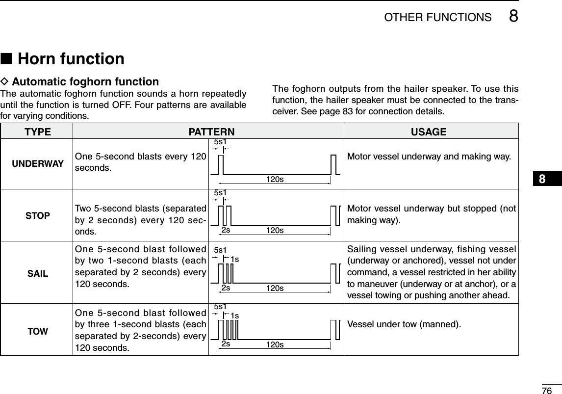
![778OTHER FUNCTIONSq Enter “Auto Foghorn” in the HORN menu. D Manual Horn functionq Push [HORN] to enter the Horn mode.w Hold down [HORN] to sound a horn.s7HILEHOLDINGDOWN;(/2.=THEHORNSOUNDSANDTHESCREENbelow is displayed. s4OADJUSTTHEHORNVOLUMELEVELROTATE$IALe Push [EXIT] to return to the normal operating screen.While in the Horn mode, the transmit and receive functions are disabled. When the transceiver is transmitting, the Horn function is disabled. eMENUf ¶ eHORNf ¶ eAuto Foghornf (Push [MENU]) (Select icon) (Rotate Dial, then push [ENT].)Appearsw Rotate dial or push [Y]/[Z] to select the desired foghorn pat-tern, and then push [ENT}.e Rotate dial or push [Y]/[Z] to adjust the foghorn level. s4HEFOGHORNLEVELISADJUSTABLEIN20 steps.r Push [MENU] to exit the MENU screen. s4HEHORNICONISDISPLAYEDt To return to normal operation, select [OFF] in the Auto Fog-horn menu.](https://usermanual.wiki/ICOM-orporated/357000/User-Guide-2220780-Page-86.png)
![788OTHER FUNCTIONS12345678910111213141516 N Voice scrambler operation The voice scrambler provides private communications. In order to receive or send scrambled transmissions, you must activate the scrambler function. You also need to program the scrambler code in the Menu screen. (p.98)q Select an operating channel except Channel 16, 70 or weather channels.w Push to turn the Voice Scrambler ON or OFF. s4HE)CONAPPEARSWHENTHEVOICESCRAMBLERIS/.D Programming scrambler codesThere are 32 codes (1 to 32) available for programming. Set the code in the SET mode. In order to understand each other, all transceivers in your group must have the same scramble code, as well as the same scrambler unit. See page 98 for scrambler code setting details.Voice recorder function NThis transceiver has automatic recording function which can record the last 120 seconds of the receiving signal. This voice recorder uses EEPROM to save the recorded voice data. EEPROM needs to be changed when it is used more than 30,000 hours. Contact your Icom dealer or distrib-uter for advice.q Start recording automatically when the signal is received. s;2%#=APPEARSWHILERECORDING s3TOP recording 3 seconds after the signal is lost.w Push [PLAY] to play back the recorded voice.s appears while playing.e Push [STOP] to return to nor-mal operating screen.](https://usermanual.wiki/ICOM-orporated/357000/User-Guide-2220780-Page-87.png)
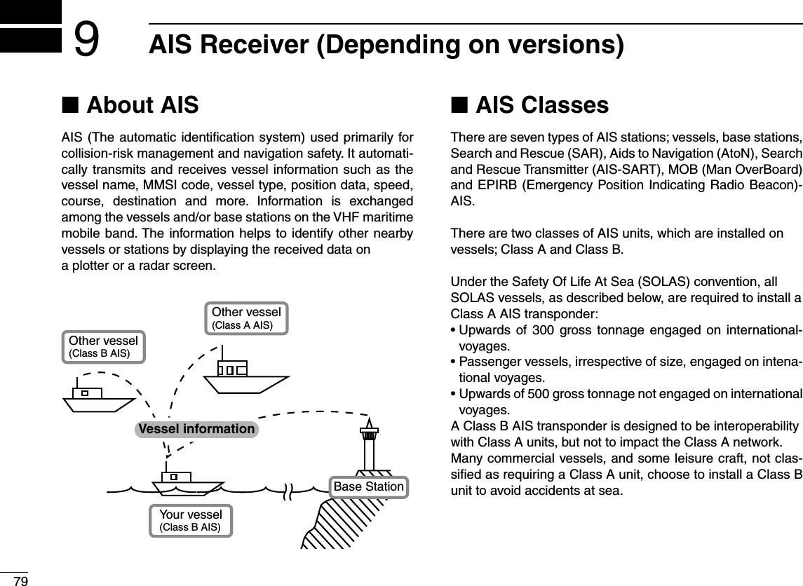
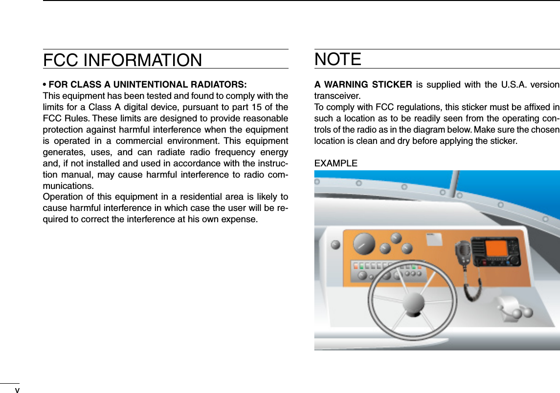
![809AIS Receiver (Depending on versions)Function display NThere are three display types; plotter, target list and danger list, and you can select your desired type using the [DISP] key.q Push [MENU].w Select AIS in the menu screen. s!)3PLOTTERAPPEARSONTHEDISPLAYe Push [Y](CH) or [Z](CH) to adjust the plotter range.D Plotter displayAfter select AIS in the menu screen, the plotter display appears.If the GPS is connected and it receives signals from a satellite. It shows the display range and the icons of the AIS targets.q DISPLAY TYPE Shows the selected display type. You can select the dis-play type from “AIS SET” in the menu screen (P.87)s7HENh.50vISDISPLAYEDTHETOPOFTHEPLOTTERDISPLAYREPRE-sents North.s7HENh!#50vISDISPLAYEDTHETOPOFTHEPLOTTERDISPLAYREPRE-sents the direction your course is heading.w RANGE/CPA INFORMATION ± Shows the range information from your vessel to the se-lected AIS target. ± Shows the CPA (Closest Point of Approach) information of the selected AIS target whose CPA is within 6 nm (nautical miles) and TCPA (Time to CPA) is within 60 minutes of your vessel.e BEARING/TCPA INFORMATION ± Shows the bearing information from your vessel to the selected AIS target. ± Shows TCPA information of the selected AIS target whose CPA is within 6 nm (nautical miles) and TCPA is within 60 minutes of your vessel.r TARGET BOX Shows the selected AIS target.s7HEN A TARGET BOX APPEARS PUSH [ENT] to display the detail screen of the selected AIS target.123467810111213141516rytqew49](https://usermanual.wiki/ICOM-orporated/357000/User-Guide-2220780-Page-89.png)
 or [√](CH) to select display range. sNMNAUTICALMILESAREselectable. s$ESCRIPTIONOFTHEICONSIcon DescriptionAIS target: VesselThe tip of the target triangle automatically points in the direction it’s heading.The icon blinks when the AIS target is closer than your CPA and TCPA settings. (Dangerous target)AIS target: Lost target*The target triangle is marked with a diagonal line.AIS target: Base StationAIS target: Search and Rescue (SAR)AIS target: Aids to Navigation (AtoN)WaypointAIS target: AIS-SART, MOB and EPIRB-AIS* A vessel is regarded as a “Lost target” after a specified period of time has passed since the vessel last transmitted data. The “Lost target” icon disappears from the plotter display 6 minutes and 40 seconds after the vessel was regarded as a “Lost target.” Ask your dealer for details.](https://usermanual.wiki/ICOM-orporated/357000/User-Guide-2220780-Page-90.png)
![829AIS Receiver (Depending on versions)12345678910111213141516D Target list displayIn the plotter display, push [DISP] to switch to the target list display, which shows all AIS targets being detected by the transponder.The AIS target data is sorted by the distance from your ves-sel, and the closest target is located on the top of the list. s Push [∫] or [√] to select an AIS target. s Push [INFO] to display the detail screen of the selected AIS tar-get. (p. 83) s Push [DSC] to transmit DSC call to selected AIS target. qwq THE NUMBER OF TARGETS Shows the number of AIS targets which are being detected by the transponder.w TARGET INFORMATION Shows the following AIS target information: s--3)CODEORNAME, if the name is programmed. s2ANGE2.'FROMYOURVESSELTOTHETARGETUNITNAUTICALMILE s"EARING"2'FROMYOURVESSELTOTHETARGETUNITDEGREED Danger list displayIn the target list display, push [DISP] to switch to the dan-ger list display, which helps you to find any dangerous target whose CPA is within 6 nm (nautical miles) and TCPA is within 60 minutes of your vessel. s Push [∫] or [√] to select an AIS target. s Push [INFO] to display the detail screen of the selected AIS tar-get. (p. 83)qwq THE NUMBER OF DANGEROUS TARGETS Shows the number of AIS targets which are being detected by the transponder.w DANGER TARGET INFORMATION Shows the following dangerous target information: s--3)CODEORNAME, if the name is programmed. s#0! #LOSEST0OINTOF!PPROACHUNITNAUTICALMILE s4#0!4IMETO#0!UNITMINUTE](https://usermanual.wiki/ICOM-orporated/357000/User-Guide-2220780-Page-91.png)
![839AIS Receiver (Depending on versions)About the detail screen NThe detail screen shows information about the selected AIS target. The contents differ, depending on the AIS class.In the detail screen, pushing [CLEAR] returns to the previous screen, which was displayed before entering the details screen.s Push [CLEAR] returns to the previous screen.s Rotate Dial or push [Ω]/[≈] to scroll the page.Example of detail screenD Content lists of Class A vessels’ DETAIL screenss!)3#LASSs--3)#ODEs3HIP.AMEs#OUNTRY.AMEs#ALL3IGNs)-/.UMBERs#0! #LOSEST 0OINT OFapproachs4#0!TIMETO#0!s0OSITION,ATITUDELongitude)s3PEED/VER'ROUNDs#OURSE/VER'ROUNDs(EADINGs0OSITION!CCURACY(H: High, L: Low)s2ANGEs"EARINGs2ATE/F4URNs"OWTO!NTENNALENGTHs3TERNTO!NTENNALENGTHs0ORTSIDETO!NTENNAlengths Starboard side to Antenna lengths,ENGTHs"EAMs$RAUGHTs4YPEOF3HIPs.AVIGATION3TATUSs$ESTINATIONs$ATEs4IME](https://usermanual.wiki/ICOM-orporated/357000/User-Guide-2220780-Page-92.png)
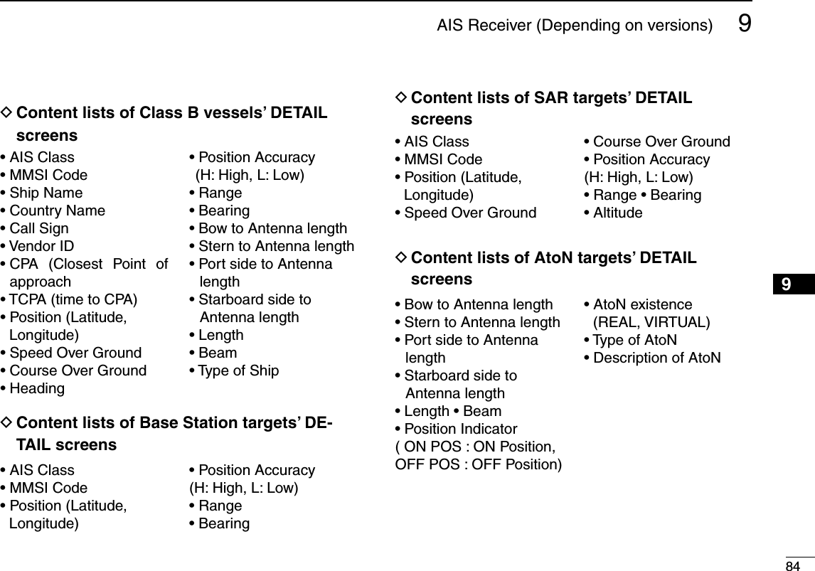
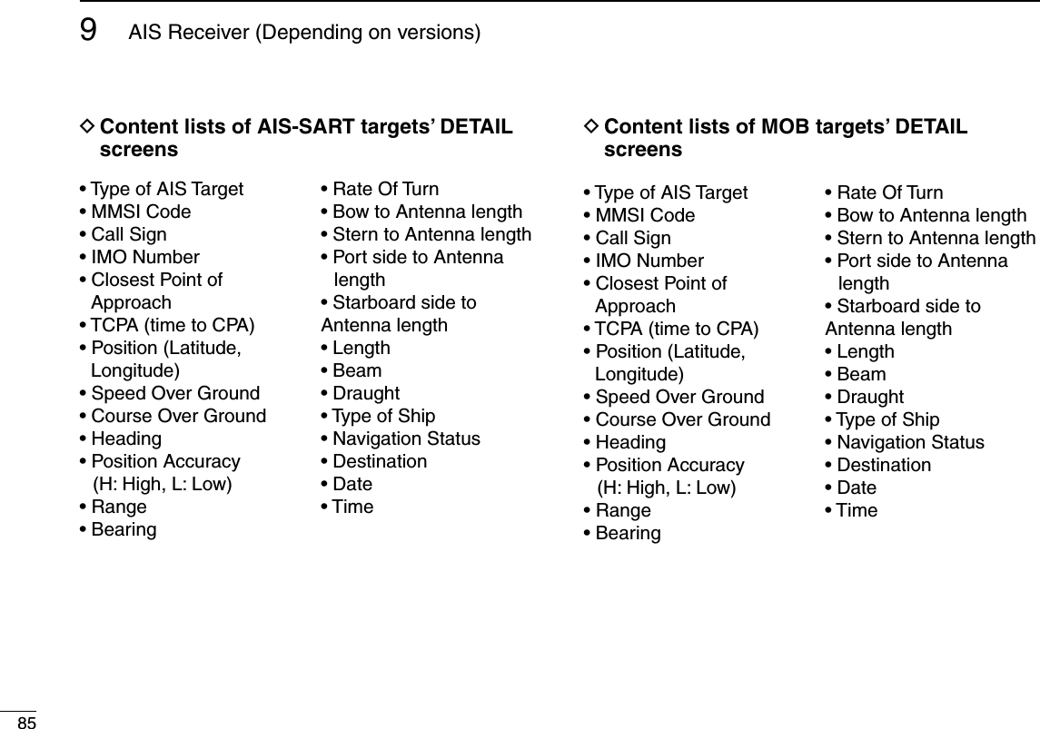
![869AIS Receiver (Depending on versions)12345678910111213141516D Content lists of EPIRB-AIS targets’ DETAIL screenss4YPEOF!)34ARGETs--3)#ODEs#ALL3IGNs)-/.UMBERs #LOSEST 0OINT OF !P-proachs4#0!TIMETO#0!s0OSITION,ATITUDELongitude)s3PEED/VER'ROUNDs#OURSE/VER'ROUNDs(EADINGs0OSITION!CCURACY(H: High, L: Low)s2ANGEs"EARINGs2ATE/F4URNs"OWTO!NTENNALENGTHs3TERNTO!NTENNALENGTHs0ORTSIDETO!NTENNAlengths Starboard side to Antenna lengths,ENGTHs"EAMs$RAUGHTs4YPEOF3HIPs.AVIGATION3TATUSs$ESTINATIONs$ATEs4IMED AIS combo displayAIS plotter can be displayed in transceiver mode. q Push [AIS] to display AIS plotter on the left side of screen. ± Push [∫](CH) or [√](CH) to select an operating chan-nel. ± Push [Ω] and [≈] or [Ω] and [≈] to select vessel. sA soft key [INFO] will appear. ± Push [INFO] or [ENT] to display the detail screen of the selected AIS target.](https://usermanual.wiki/ICOM-orporated/357000/User-Guide-2220780-Page-95.png)
![879AIS Receiver (Depending on versions)AIS Settings NAIS settings can be customized from “AIS SET” in the menu screen..q Push [MENU].w Rotate Dial or push [Ω]/[≈] to select “AIS SET” icon and then push the soft key below the icon. s!)3SETTINGSMENUAPPEARSONTHEDISPLAYD.ORTHUP#/'50Select the display type for AIS plotter.s7HENh.ORTHUPvISDISPLAYEDTHETOPOFTHEPLOTTERDISPLAYREP-resents North.s7HENh#OGUPvISDISPLAYEDTHETOPOFTHEPLOTTERDISPLAYREPRE-sents the direction your course is heading.D CPA/TCPAIn this menu, you can edit alarm settings for AIS receiver.s!LARMYou can turn the collision alarm function ON or OFF.](https://usermanual.wiki/ICOM-orporated/357000/User-Guide-2220780-Page-96.png)
 or [Z](CH) to input the value between 0.1 and 4.9 kt (in 0.1 kt steps), or select OFF. (default: 1.0 kt)w Push [ENT] to save and return to the Menu mode.NOTE: If other vessels at anchor or drifting come into your alarm zone, the Slow Warn alarm will sound again. Only ifthe previous vessel disappears from the Dangerous List (p. 82), and then re-enters the list, can a new Slow Warn or regular alarm sound, depending on the vessels SOG, or CPA and TCPA. The Slow Warn function operates in the same way if your vessel is at anchor and other vessels enter your alarm zone area.s#0!4#0!Enter CPA (Closest Point of Approach) and TCPA (Time to CPA) values.These settings help you find a dangerous target to avoid a collision. The icon blinks on the plotter display and/or the alarm buzzer sounds, when the AIS target is closer than your CPA and TCPA settings.q Push [Y](CH) or [Z](CH) to select either “CPA” or “TCPA.” s#0!OR4#0!SETTINGMENUAPPEARSONTHEDISPLAYw Push [Y](CH) or [Z](CH) to input the value into that item.s#0!"ETWEENANDNMINNMSTEPS(default: 1.5 nm) s4#0!"ETWEENANDMINUTESINMINUTESTEPS(default: 20 min)e Repeat steps q and w to input the value into the other item.r Push [CLEAR] to save and return to the Menu mode.When the CPA setting menu is selected.When the TCPA setting menu is selected.](https://usermanual.wiki/ICOM-orporated/357000/User-Guide-2220780-Page-97.png)
![89NMEA 2000 Connection (Depending on versions)10Description NNMEA 2000 is a communication standard used for connect-ing various marine censors and display units in the vessel. IC-M506 can easily connect to a NMEA 2000 network with its plug-and-play functionality and display the information pro-vided from the devices in the network.D NMEA 2000 settingsSelect the censors in NMEA 2000 network which sends data to the transceiver. q Enter “NMEA 2000”menu in the menu screen.w Select the type of data from the menu screen and push [ENT].w The transceiver starts searching the devices connected to NMEA 2000 network.e The list of connected censor is displayed.r Select the censor to send the data to transceiver and push [ENT]. s3ELECTh.OT 5SEDvIF THETRANSCEIVERIS RECEIVING THEDATA FROMthe censor with NMEA 0183. The transceiver uses the data from NMEA 2000 if it is received from both network.t Push [MENU] to exit the MENU screen. eMENUf ¶ eNMEA 2000f (Push [MENU]) (Select icon)](https://usermanual.wiki/ICOM-orporated/357000/User-Guide-2220780-Page-98.png)
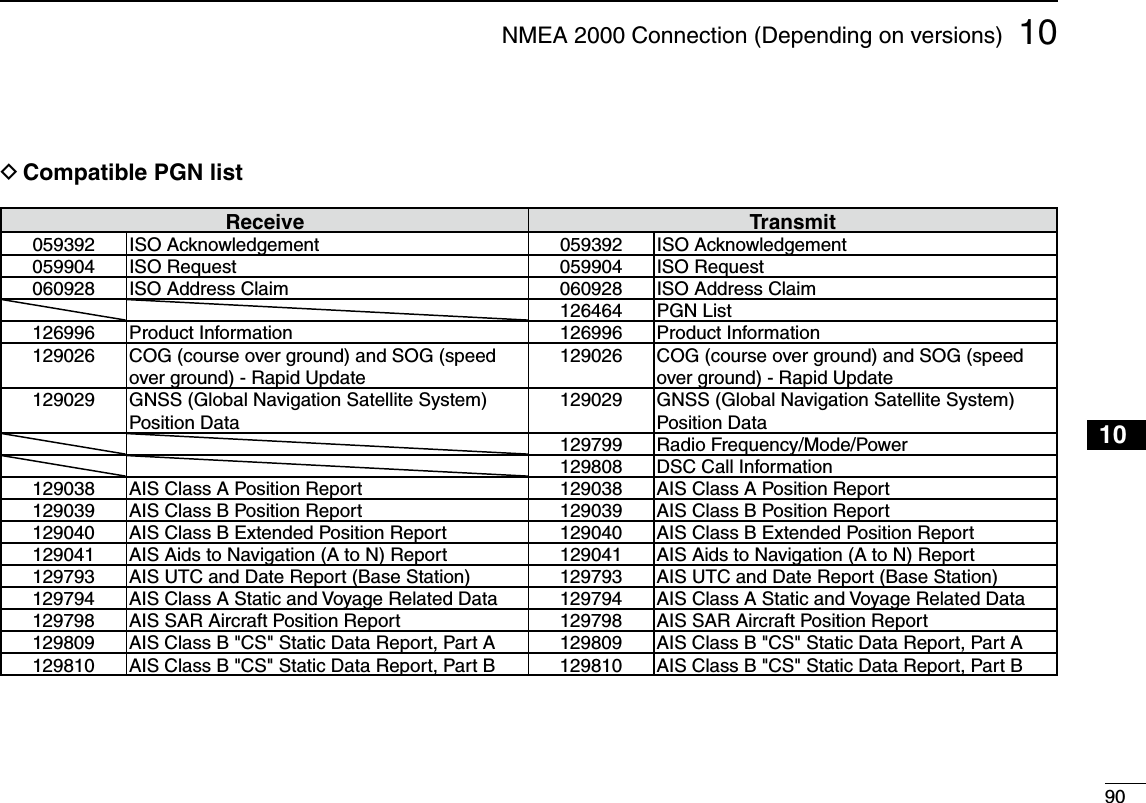
![91MENU SCREEN OPERATION11 NMenu screen operationThe Menu screen is used for programming infrequently changed values, function settings or sending DSC calls. DEntering the Menu screen and operation%XAMPLE Set the channel group to “INT.”q Push [MENU].w Rotate Dial or push [Ω]/[≈] to select “RADIO SET” icon and then push the soft key below the icon.e Rotate Dial or push [∫]/[√] to se-lect “CHAN Group,” and then push [ENT]. Rotate Dial or push [ r∫]/[√] to select “USA,” and then push [ENT] to set it.sh” is displayed next to “INT.” tPush [EXIT] to exit the Menu screen. s0USH ;#,%!2= OR ;"!#+= TO RETURN TOthe previous screen.CLEARMENUENTCHCH[ENT][Y]/[Z][CLEAR][EXIT] [ENT][BACK] Dial[MENU]Menu icons](https://usermanual.wiki/ICOM-orporated/357000/User-Guide-2220780-Page-100.png)
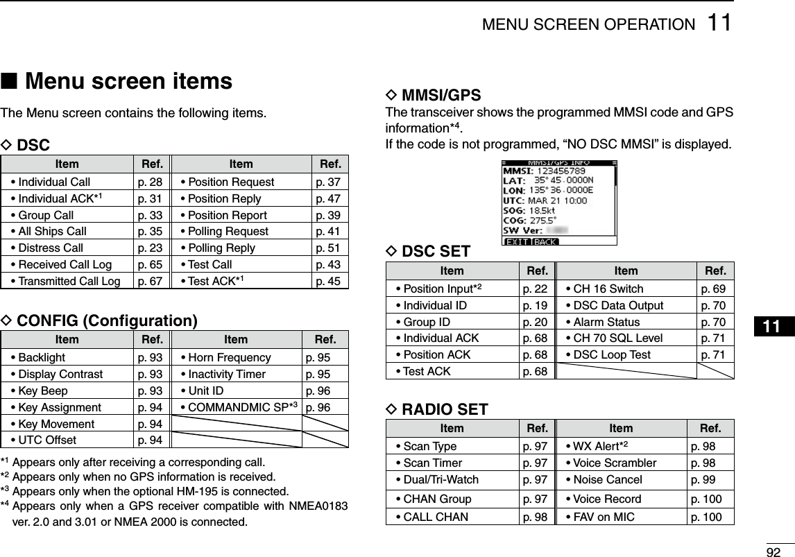
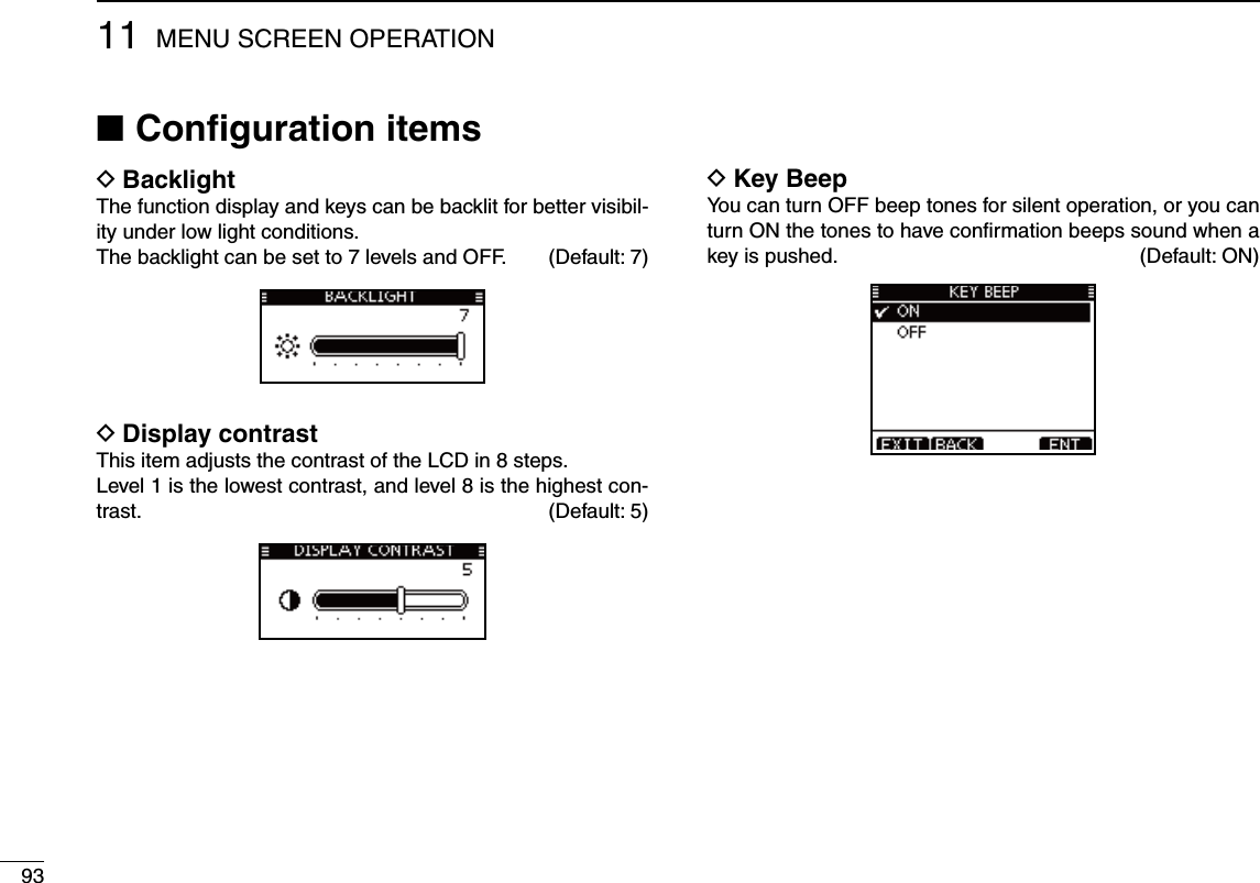
![9411MENU SCREEN OPERATION12345678910111213141516D Key AssignmentDesired functions can be assigned to soft keys.The assigned function can be used when its key icon is displayed.See page 3 for details of the assignable key functions.q Rotate Dial or push [∫]/[√] to select the desired position, and then push [ENT].s4ORETURNTOTHEDEFAULTSELECTh3ETDEFAULTvANDPUSH;%.4=w Rotate Dial or push [∫]/[√] to select the option, and then push [ENT] to set it.sh” is displayed next to the selected option. * [CHAN] appears instead of [CH/WX] only for Chinese version transceiver.e Push [EXIT] to exit the Menu screen. s0USH;#,%!2=OR;"!#+=TORETURNTOTHEPREVIOUSSCREEND Key MovementSet the movement of soft key icons and menu icons. You can select from 2 types of movement, “Single” or “Group”.UTC Offset DSet the offset time between the UTC (Universal Time Coordi-nated) and your local time to between –14:00 and +14:00 (in 1 minute steps). (Default: 00:00)](https://usermanual.wiki/ICOM-orporated/357000/User-Guide-2220780-Page-103.png)
![9511 MENU SCREEN OPERATIOND Horn FrequencySet audio frequency of the foghorn. s!VAILABLEFREQUENCYRANGEIS(ZTO(ZIN(ZSTEPSD Inactivity TimerSet the inactivity timer to between 1 and 10 minutes (in 1 min-ute steps) or OFF for the “Not DSC Related” and “DSC Re-lated” item, and set to between 1 and 15 minutes (in 1 minute steps) or OFF for the “DSC Related” item. The count down alarm sounds 10 seconds before the Inactive timer returns the current screen to the normal operating screen. When the “INACTIVITY TIMER” screen is displayed, rotate qDial or push [∫]/[√] to select “Not DSC Related” or “DSC Related,” and then push [ENT]. Rotate Dial or push [ w∫]/[√] to select the option, and then push [ENT] to set it.sh” is displayed next to the selected option.Push [EXIT] to exit the Menu screen. e s0USH;#,%!2=OR;"!#+=TORETURNTOTHEPREVIOUSSCREEN](https://usermanual.wiki/ICOM-orporated/357000/User-Guide-2220780-Page-104.png)
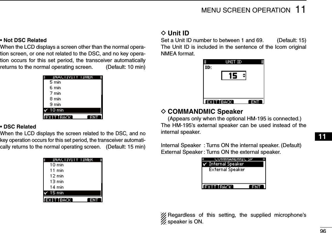
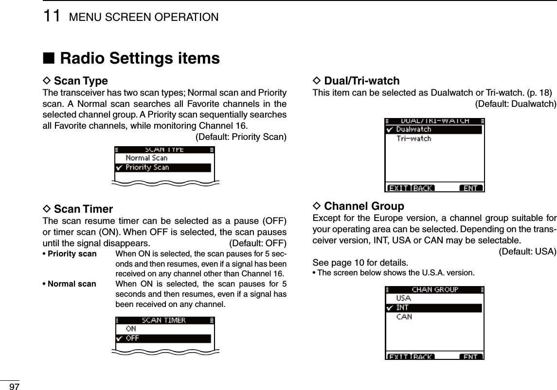
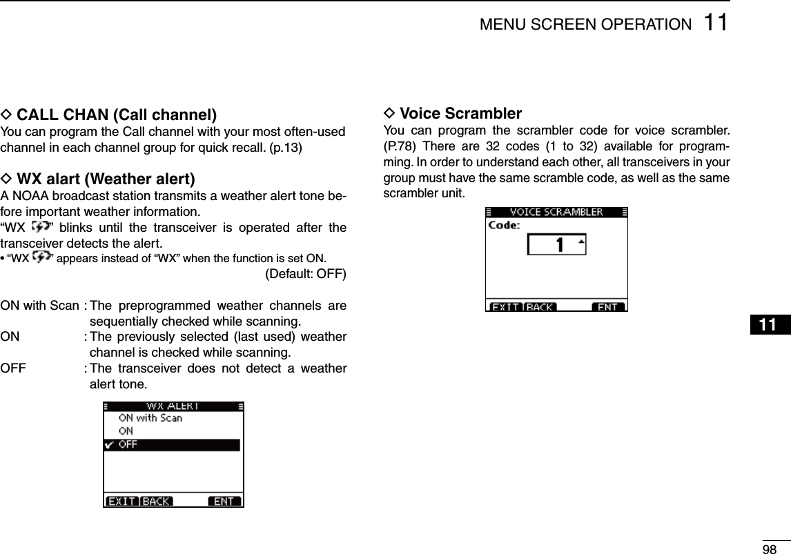
![9911 MENU SCREEN OPERATIOND Noise CancelSet the Noise Cancel function for both receive and transmit. qWhen the “NOISE CANCEL” screen is displayed, rotate Dial or push [∫]/[√] to select “RX” or “TX,” and then push [ENT]. Rotate Dial or push [ w∫]/[√] to select the option, and then push [ENT] to set it.sh” is displayed next to the selected option. Push [EXIT] to exit the Menu screen. e s0USH;#,%!2=OR;"!#+=TORETURNTOTHEPREVIOUSSCREENs28Turn the receive Noise Cancel function ON or OFF. OFF : Turns OFF the function. (Default)1 : The Noise Cancel function reduces random noise com-ponents in the received signal to approximately one half.2 : The Noise Cancel function reduces random noise com-ponents in the received signal to approximately one third.3 : The Noise Cancel function reduces random noise com-ponents in the received signal to approximately one tenth.s48Turn the transmit Noise Cancel function ON or OFF. OFF : Turns OFF the function. (Default)ON : The Noise Cancel function reduces random noise com-ponents in the transmitted signal to one third.](https://usermanual.wiki/ICOM-orporated/357000/User-Guide-2220780-Page-108.png)
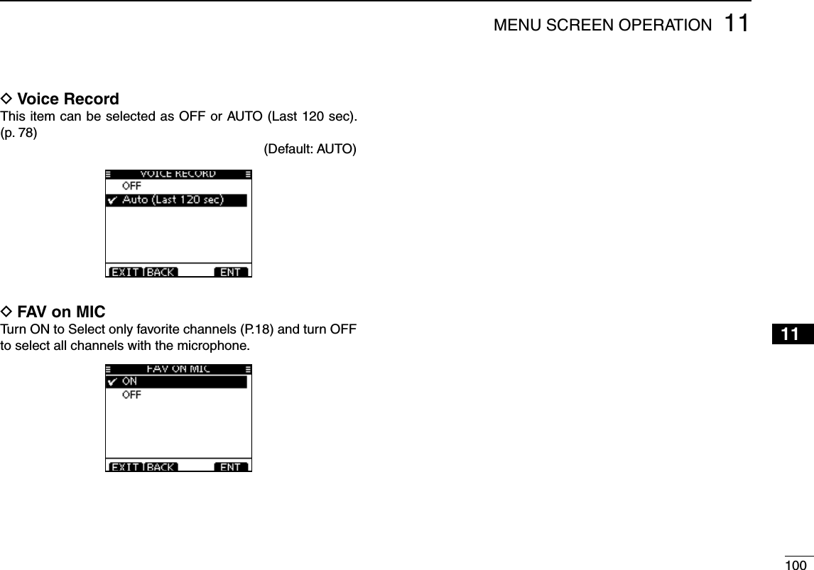
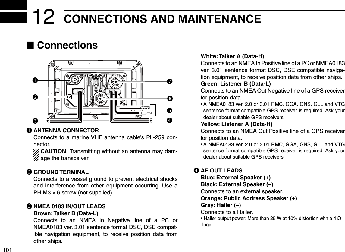
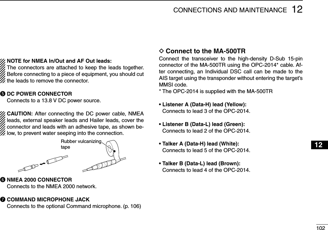
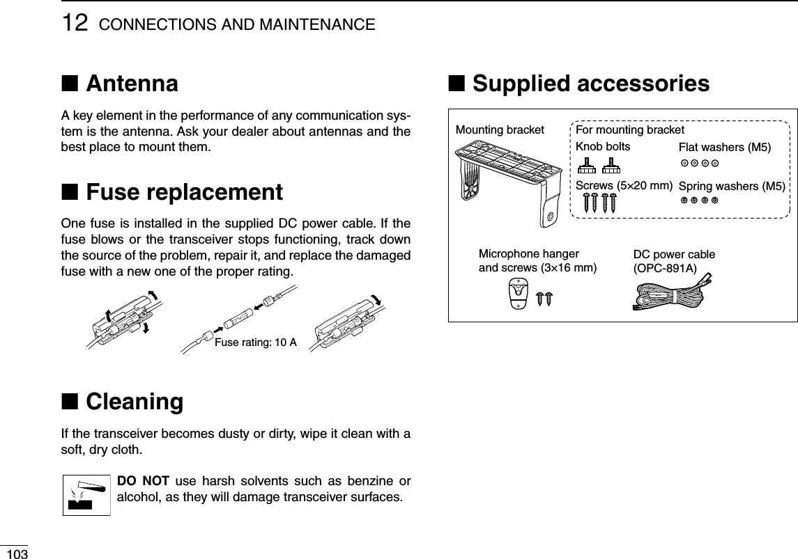
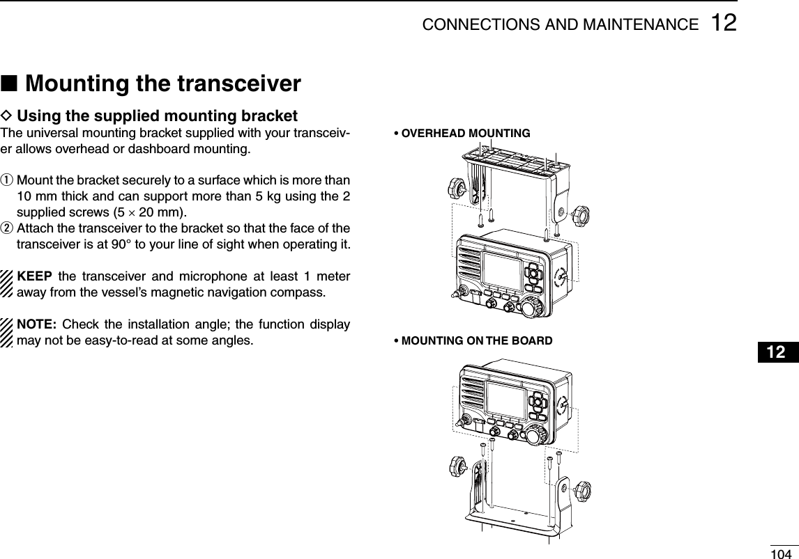
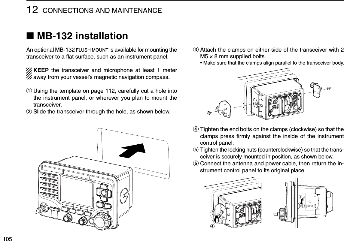
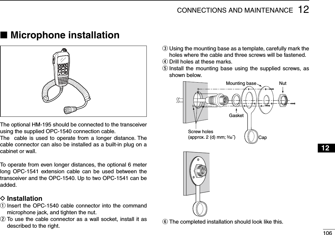
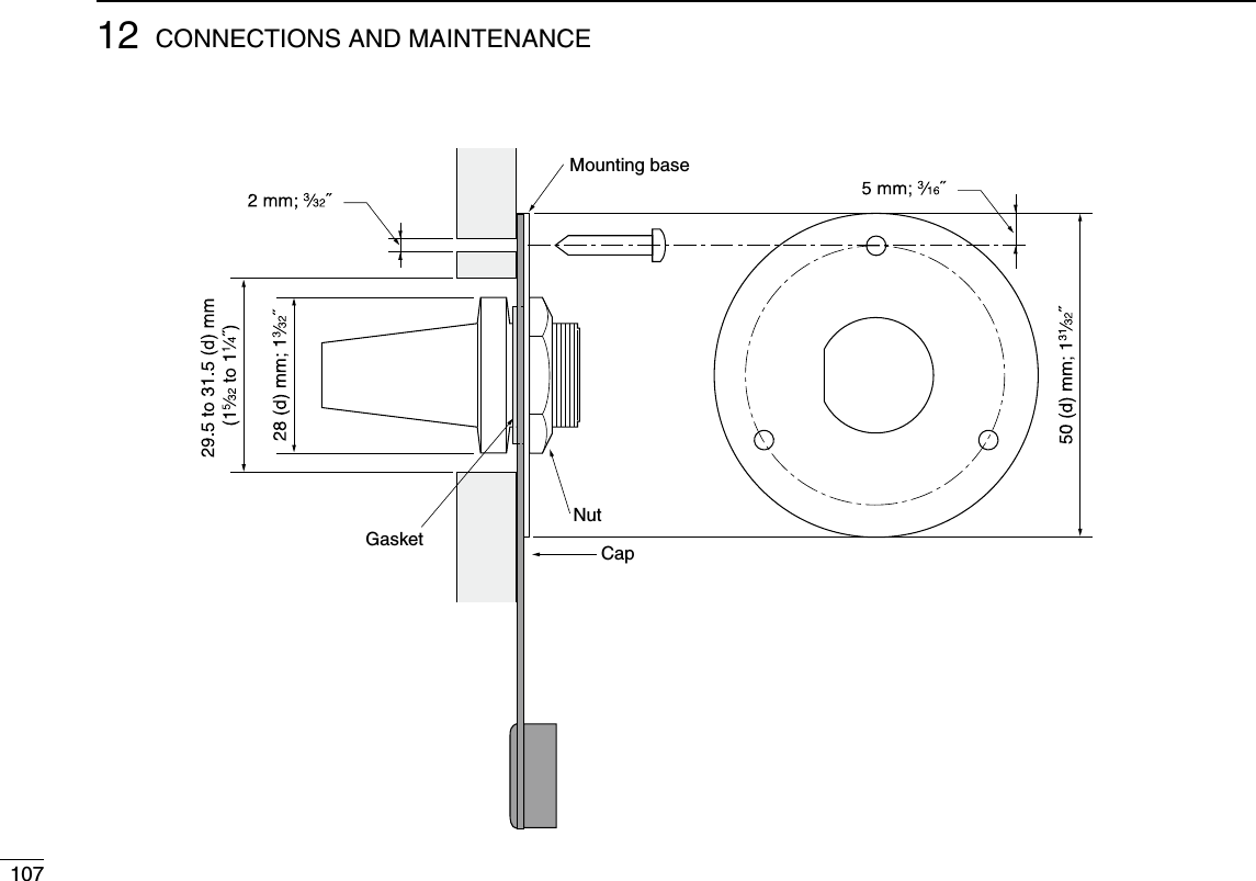
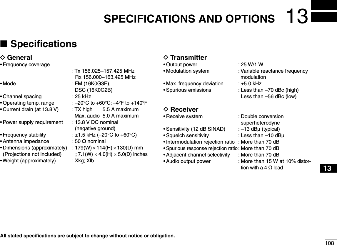
![10913 SPECIFICATIONS AND OPTIONSD Dimensions114 (4.0) 110 (4.33)157 (6.2)25(1.0) 105.0 (4.0)93 (3.7)Unit: mm (inch)179 (7.1)Options NsMB-132 FLUSH MOUNT KIT To mount the transceiver to a panel.sHM-195 COMMANDMICIV™ External microphone-type controller. Provides optional in-tercom operation. 6 m (20 ft) microphone cable and mount-ing base included. Black and white colors are available.sHM-205B/HM-205RB SPEAKER MICROPHONE Equipped with [Y]/[Z] (channel up/down,) [HI/LO] and [PTT] keys, a speaker and microphone.sOPC-1541 MICROPHONE EXTENSION CABLE 6 m (20 feet) microphone extension cable for optional HM-195 COMMANDMICIV™. Up to two OPC-1541 can be con-nected. Usable length is 18 m (60 ft) maximum.sMA-500TR CLASS B AIS TRANSPONDER To transmit individual DSC calls to a selected AIS targets.Approved Icom optional equipment is designed for optimal perfor-mance when used with an Icom transceiver.Icom is not responsible for the destruction or damage to an Icom transceiver in the event the Icom transceiver is used with equipment that is not manufactured or approved by Icom.](https://usermanual.wiki/ICOM-orporated/357000/User-Guide-2220780-Page-118.png)