ICOM orporated 357000 VHF Marine Transceiver User Manual IC M506 draft 0306
ICOM Incorporated VHF Marine Transceiver IC M506 draft 0306
User Manual

INSTRUCTION MANUAL
iM506
VHF MARINE TRANSCEIVER
This device complies with Part 15 of the FCC
Rules. Operation is subject to the condition that
this device does not cause harmful interference.
i
FOREWORD
Thank you for purchasing this Icom product. The IC-M506
VHF MARINE TRANSCEIVER is designed and built with Icom’s
state of the art technology and craftsmanship. With proper
care, this product should provide you with years of trouble-
free operation.
We appreciate you making the IC-M506 your radio of choice,
and hope you agree with Icom’s philosophy of “technology
first.” Many hours of research and development went into the
de sign of your IC-M506.
FEATURES D
M Built-in Class D DSC
M Integrated AIS Receiver
M NMEA 2000™ Connectivity
M 2 Minutes Last Call Voice Recording
M Superb Active Noise Cancelling
M 25W Two-Way Hailer and Horn
M IPX8 Submersible Plus™
M Optional COMMANDMIC
IV
™ HM-195
IMPORTANT
READ ALL INSTRUCTIONS carefully and completely
before using the transceiver.
SAVE THIS INSTRUCTION MANUAL — This in-
struction manual contains important operating instructions
for the IC-M506.
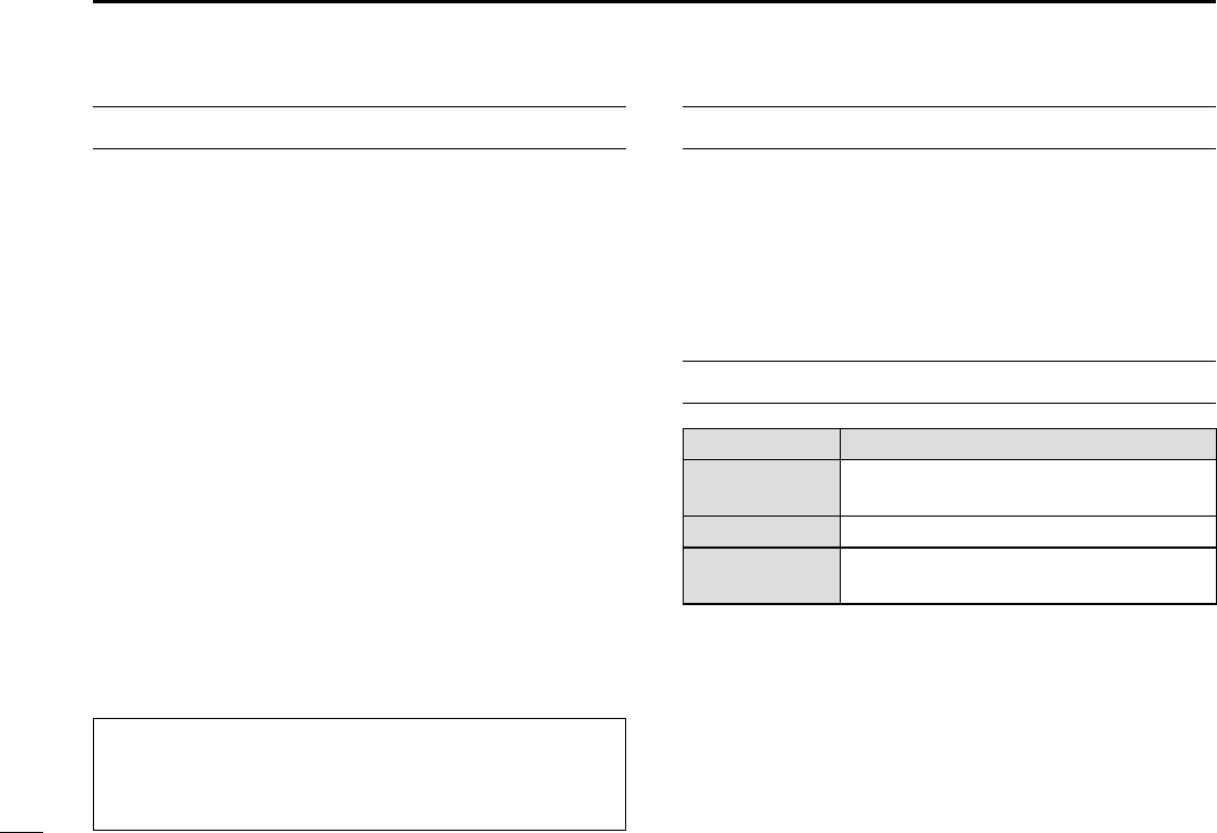
EXPLICIT DEFINITIONS
WORD DEFINITION
RWARNING! Personal injury, fire hazard or electric
shock may occur.
CAUTION Equipment damage may occur.
NOTE
If disregarded, inconvenience only. No risk
of personal injury, fire or electric shock.
CLEAN THE TRANSCEIVER AND MICROPHONE THOR-
OUGHLY WITH FRESH WATER after exposure to water
including salt, otherwise, the keys and switch may become
inoperable due to salt crystallization.
For Canada:
This device complies with RSS-310 of Industry Canada. Op-
eration is subject to the condition that this device does not
cause harmful interference.
Cet appareil est conforme au CNR-310 d’Industrie Canada.
Son exploitation est autorisee sous reserve que l’appareil ne
cause pas de brouillage prejudiciable.

If your vessel requires assistance, contact other vessels and
the Coast Guard by sending a Distress call on Channel 16.
Or, transmit your Distress call using digital selective calling
on Channel 70.
USING CHANNEL 16
DISTRESS CALL PROCEDURE
1. “MAYDAY MAYDAY MAYDAY.”
2. “THIS IS ...............” (name of vessel).
3. Say your call sign or other description of the vessel
(AND 9 digit DSC ID if you have one).
4. “LOCATED AT ...............” (your position).
5. State the nature of the distress and assistance re-
quired.
6. Give any other information which might facilitate
the rescue.
USING DIGITAL SELECTIVE CALLING (Ch 70)
DISTRESS CALL PROCEDURE
1. While lifting up the key cover, hold down [DIS-
TRESS] for 3 seconds until you hear 3 short beeps
and then one long beep.
2. Wait for an acknowledgment on Channel 70 from a
coast station.
s!FTERTHEACKNOWLEDGEMENTISRECEIVED#HANNELIS
automatically selected.
3. Hold down [PTT], then transmit the appropriate in-
formation as listed above.
ii
IN CASE OF EMERGENCY

iii
RADIO OPERATOR WARNING
WARNING
Icom requires the radio operator to meet the
FCC Requirements for Radio Frequency Expo-
sure. An omnidirectional antenna with gain not
greater than 9 dBi must be mounted a mini-
mum of 5 meters (measured from the lowest
point of the antenna) vertically above the main
deck and all possible personnel. This is the minimum safe
separation distance estimated to meet all RF exposure com-
pliance requirements. This 5 meter distance is based on the
FCC Safe Maximum Permissible Exposure (MPE) distance
of 3 meters added to the height of an adult (2 meters) and is
appropriate for all vessels.
For watercraft without suitable structures, the antenna must
be mounted so as to maintain a minimum of 1 meter verti-
cally between the antenna, (measured from the lowest point
of the antenna), to the heads of all persons AND all persons
must stay outside of the 3 meter MPE radius.
Do not transmit with radio and antenna when persons are
within the MPE radius of the antenna, unless such persons
(such as driver or radio operator) are shielded from antenna
field by a grounded metallic barrier. The MPE Radius is the
minimum distance from the antenna axis that person should
maintain in order to avoid RF exposure higher than the al-
lowable MPE level set by FCC.
FAILURE TO OBSERVE THESE LIMITS MAY ALLOW
THOSE WITHIN THE MPE RADIUS TO EXPERIENCE RF
RADIATION ABSORPTION WHICH EXCEEDS THE FCC
MAXIMUM PERMISSIBLE EXPOSURE (MPE) LIMIT.
IT IS THE RESPONSIBILITY OF THE RADIO OPERATOR
TO ENSURE THAT THE MAXIMUM PERMISSIBLE EXPO-
SURE LIMITS ARE OBSERVED AT ALL TIMES DURING
RADIO TRANSMISSION. THE RADIO OPERATOR IS TO
ENSURE THAT NO BYSTANDERS COME WITHIN THE
RADIUS OF THE MAXIMUM PERMISSIBLE EXPOSURE
LIMITS.
Determining MPE Radius
THE MAXIMUM PERMISSIBLE EXPOSURE (MPE) RA-
DIUS HAS BEEN ESTIMATED TO BE A RADIUS OF
ABOUT 3M PER OET BULLETIN 65 OF THE FCC.
THIS ESTIMATE IS MADE ASSUMING THE MAXIMUM
POWER OF THE RADIO AND ANTENNAS WITH A MAXI-
MUM GAIN OF 9dBi ARE USED FOR A SHIP MOUNTED
SYSTEM.

iv
1
2
3
4
5
6
7
8
9
10
11
12
13
14
15
16
AVERTISSEMENT POUR LES OPÉRATEURS RADIO
Icom exige que l'opérateur radio se conforme aux
exigences de la FCC en matière d'exposition aux
radiofréquences. Une antenne omnidirectionnelle
dont le gain ne dépasse pas 9dBi doit être fixée
à une distance minimale de 5 mètres (mesurée
depuis le point le plus bas de l'antenne) verticale-
ment au-dessus du pont principal et de tout le personnel qui peut
s'y trouver. Il s'agit de la distance de sécurité minimale prévue pour
satisfaire aux exigences de conformité en matière d'exposition aux
RF. Cette distance de 5 mètres est établie en fonction de l'exposition
maximale admissible sécuritaire de 3 mètres établie par la FCC, à
laquelle on ajoute la hauteur d'un adulte (2 mètres); cette distance
convient pour tous les navires.
Dans le cas des embarcations sans structure convenable, l'antenne
doit être fixée de façon à maintenir une distance minimale de 1 mètre
verticalement entre cette antenne (mesurée depuis son point le plus
bas) et la tête de toute personne présente; toutes les personnes
présentes doivent se tenir à l'extérieur d'un rayon d'exposition maxi-
male admissible de 3 mètres.
Ne pas émettre à l'aide de la radio et de l'antenne lorsque des
personnes se trouvent à l'intérieur du rayon d'exposition maximale
admissible de cette antenne, à moins que ces personnes (comme
le conducteur ou l'opérateur radio) ne soient protégées du champ
de l'antenne par un écran métallique relié à la masse. Le rayon
d'exposition maximale admissible équivaut à la distance minimale
que cette personne doit maintenir entre elle et l'axe de l'antenne pour
éviter une exposition aux RF supérieure au niveau d'exposition maxi-
male admissible fixé par la FCC.
LE NON-RESPECT DE CES LIMITES PEUT CAUSER, POUR LES
PERSONNES SITUÉES DANS LE RAYON D'EXPOSITION MAXI-
MALE ADMISSIBLE, UNE ABSORPTION DE RAYONNEMENT DE
RF SUPÉRIEURE À L'EXPOSITION MAXIMALE ADMISSIBLE
FIXÉE PAR LA FCC.
L'OPÉRATEUR RADIO EST RESPONSABLE D'ASSURER QUE
LES LIMITES D'EXPOSITION MAXIMALE ADMISSIBLE SOIENT
RESPECTÉES EN TOUT TEMPS PENDANT LA TRANSMISSION
RADIO. L'OPÉRATEUR RADIO DOIT S'ASSURER QU'AUCUNE
PERSONNE PRÉSENTE NE SE SITUE À L'INTÉRIEUR DU RAY-
ON D'EXPOSITION MAXIMALE ADMISSIBLE.
Établir le rayon d'exposition maximale admissible
ON ESTIME QUE LE RAYON D'EXPOSITION MAXIMALE ADMIS-
SIBLE EST D'ENVIRON 3 M, TEL QUE STIPULÉ DANS LE BUL-
LETIN OET 65 DE LA FCC. CETTE DISTANCE ESTIMÉE TIENT
COMPTE D'UN SYSTÈME INSTALLÉ SUR UN NAVIRE UTILISANT
LA PUISSANCE MAXIMALE DE LA RADIO ET DES ANTENNES
DONT LE GAIN MAXIMAL EST DE 9dBi.
AVERTISSEMENT

v
FCC INFORMATION
s&/2#,!33!5.).4%.4)/.!,2!$)!4/23
This equipment has been tested and found to comply with the
limits for a Class A digital device, pursuant to part 15 of the
FCC Rules. These limits are designed to provide reasonable
protection against harmful interference when the equipment
is operated in a commercial environment. This equipment
generates, uses, and can radiate radio frequency energy
and, if not installed and used in accordance with the instruc-
tion manual, may cause harmful interference to radio com-
munications.
Operation of this equipment in a residential area is likely to
cause harmful interference in which case the user will be re-
quired to correct the interference at his own expense.
NOTE
A WARNING STICKER is supplied with the U.S.A. version
transceiver.
To comply with FCC regulations, this sticker must be affixed in
such a location as to be readily seen from the operating con-
trols of the radio as in the diagram below. Make sure the chosen
location is clean and dry before applying the sticker.
EXAMPLE

vi
PRECAUTIONS
RWARNING! NEVER
connect the transceiver to an AC
outlet. This may pose a fire hazard or result in an electric shock.
RWARNING! NEVER connect the transceiver to a pow-
er source of more than 13V DC or use reverse polarity. This
will ruin the transceiver.
RWARNING! NEVER cut the DC power cable between
the DC plug at the back of the transceiver and fuse holder. If
an incorrect connection is made after cutting, the transceiver
may be damaged.
#!54)/. .%6%2
place the transceiver where normal
operation of the vessel may be hindered or where it could
cause bodily injury.
KEEP the transceiver and microphone at least 1 m away
from the vessel’s magnetic navigation compass.
DO NOT use or place the transceiver in areas with tem-
peratures below –20°C (–4°F) or above +60°C (+140°F) or, in
areas subject to direct sunlight, such as the dashboard.
DO NOT use harsh solvents such as benzine or alcohol to
clean the transceiver, as they will damage the transceiver’s
surfaces. If the transceiver becomes dusty or dirty, wipe it
clean with a soft, dry cloth.
DO NOT disassemble or modify the transceiver for any rea-
son.
BE CAREFUL! The transceiver rear panel will become
hot when operating continuously for long periods of time.
Place the transceiver in a secure place to avoid inadvertent
use by children.
BE CAREFUL! The transceiver meet IPX8 requirements
and the optional HM-195 COMMANDMICIV™ meet IPX7 re-
quirements for waterproof protection. However, once the
transceiver has been dropped, waterproof protection cannot
be guaranteed because of possible damage to the transceiv-
er’s case or the waterproof seal.
* Except for the DC power connector, NMEA In/Out leads and AF
Out leads.
For U.S.A. only
#!54)/. Changes or modifications to this device, not ex-
pressly approved by Icom Inc., could void your authority to
operate this device under FCC regulations.
Icom, Icom Inc. and the Icom logo are registered trademarks of Icom Incor-
porated (Japan) in Japan, the United States, the United Kingdom, Germany,
France, Spain, Russia and/or other countries.
COMMANDMIC is a registered trademark of Icom Incorporated (Japan) in Ja-
pan and the United States.

vii
TABLE OF CONTENTS
FOREWORD .........................................................................i
IMPORTANT .......................................................................... i
EXPLICIT DEFINITIONS .......................................................i
IN CASE OF EMERGENCY ................................................. ii
RADIO OPERATOR WARNING .......................................... iii
AVERTISSEMENT POUR LES OPÉRATEURS RADIO ...... iv
FCC INFORMATION ............................................................v
NOTE .................................................................................... v
PRECAUTIONS ................................................................... vi
TABLE OF CONTENTS ...................................................... vii
1 OPERATING RULES .......................................................1
2 PANEL DESCRIPTION .................................................2-7
Front panel N ...................................................................2
Function display N ...........................................................5
Speaker Microphone N .................................................... 7
Soft key function N ...........................................................7
3 PREPARATION................................................................8
MMSI code programming N .............................................8
4 BASIC OPERATION ...................................................9-15
Channel selection N ........................................................9
Receiving and transmitting N .........................................11
Call channel programming N .........................................13
Channel name programming N......................................13
Microphone Lock function N ..........................................14
Adjusting the display back-light level N ..........................15
AquaQuake water draining function N ...........................15
5 SCAN OPERATION ..................................................16-17
Scan types N .................................................................16
Setting Favorite channels N ........................................... 17
Starting a scan N ........................................................... 17
6 DUALWATCH/TRI-WATCH ............................................18
Description N .................................................................18
Operation N ...................................................................18
7 DSC OPERATION ....................................................19-73
DSC address ID N ........................................................19
Position and time programming N..................................22
Distress call N ................................................................23
Transmitting DSC calls N ............................................... 28
Receiving DSC calls N ..................................................53
Received Call log N .......................................................65
Transmitted Call log N....................................................67
DSC Settings N .............................................................68
Making an Individual call using an AIS transponder N ..72
8 OTHER FUNCTIONS ................................................74-78
Intercom operation N .....................................................74
RX Speaker function N ..................................................75
Hailer operation N ..........................................................75
Horn function N ..............................................................76

viii
1
2
3
4
5
6
7
8
9
10
11
12
13
14
15
16
Voice scrambler operation N ........................................ 78
Voice recorder function N ..............................................78
9 AIS Receiver (Depending on versions) .................79-88
About AIS N ................................................................... 79
AIS Classes N ...............................................................79
Function display N .........................................................80
About the detail screen N ..............................................83
AIS Settings N ...............................................................87
10 NMEA 2000 Connection (Depending on versions)....89
Description N .................................................................89
11 MENU SCREEN OPERATION ...............................91-100
Menu screen operation N ..............................................91
Menu screen items N .....................................................92
Configuration items N ....................................................93
Radio Settings items N ..................................................97
12 CONNECTIONS AND MAINTENANCE ...............101-107
Connections N .............................................................101
Antenna N ....................................................................103
Fuse replacement N ....................................................103
Cleaning N ................................................................... 103
Supplied accessories N ...............................................103
Mounting the transceiver N .......................................... 104
MB-132 installation N ..................................................105
Microphone installation N ............................................106
13 SPECIFICATIONS AND OPTIONS ......................108-109
Specifications N ........................................................... 108
Options N .....................................................................109
14 CHANNEL LIST ...........................................................110
15 TROUBLESHOOTING .................................................111
16 TEMPLATE ..................................................................112

1
OPERATING RULES
1
D Priorities
s2EADALL RULES AND REGULATIONS PERTAININGTO CALL PRIORITIES
and keep an up-to-date copy handy. Safety and distress
calls take priority over all others.
s9OUMUSTMONITOR#HANNELWHENYOUARENOTOPERATING
on another channel.
s&ALSEORFRAUDULENTDISTRESSCALLSAREPROHIBITEDUNDERLAW
Privacy D
s)NFORMATIONOVERHEARDBUTNOTINTENDEDFORYOUCANNOTLAW-
fully be used in any way.
s)NDECENTORPROFANELANGUAGEISPROHIBITED
Radio licenses D
(1) SHIP STATION LICENSE
You may require a current radio station license before using
the transceiver. It is unlawful to operate a ship station which is
not licensed, but required to be.
If required, contact your dealer or the appropriate govern-
ment agency for a Ship-Radiotelephone license application.
This government-issued license states the call sign which is
your craft’s identification for radio purposes.
(2) OPERATOR’S LICENSE
A Restricted Radiotelephone Operator Permit is the license
most often held by small vessel radio operators when a radio
is not required for safety purposes.
If required, the Restricted Radiotelephone Operator Permit
must be posted or kept with the operator. If required, only a
licensed radio operator may operate a transceiver.
However, non-licensed individuals may talk over a transceiver
if a licensed operator starts, supervises, ends the call and
makes the necessary log entries.
A current copy of the applicable government rules and regu-
lations is only required to be on hand for vessels in which
a radio telephone is compulsory. However, even if you are
not required to have these on hand it is your responsibility to
be thoroughly acquainted with all pertinent rules and regula-
tions.
./4%Even though the transceiver is capable of opera-
tion on VHF marine channels 3, 21, 23, 61, 64, 81, 82 and
83, according to FCC regulations these simplex channels
cannot be lawfully used by the general population in USA
waters.
2
2
PANEL DESCRIPTION
1
2
3
4
5
6
7
8
9
10
11
12
13
14
15
16
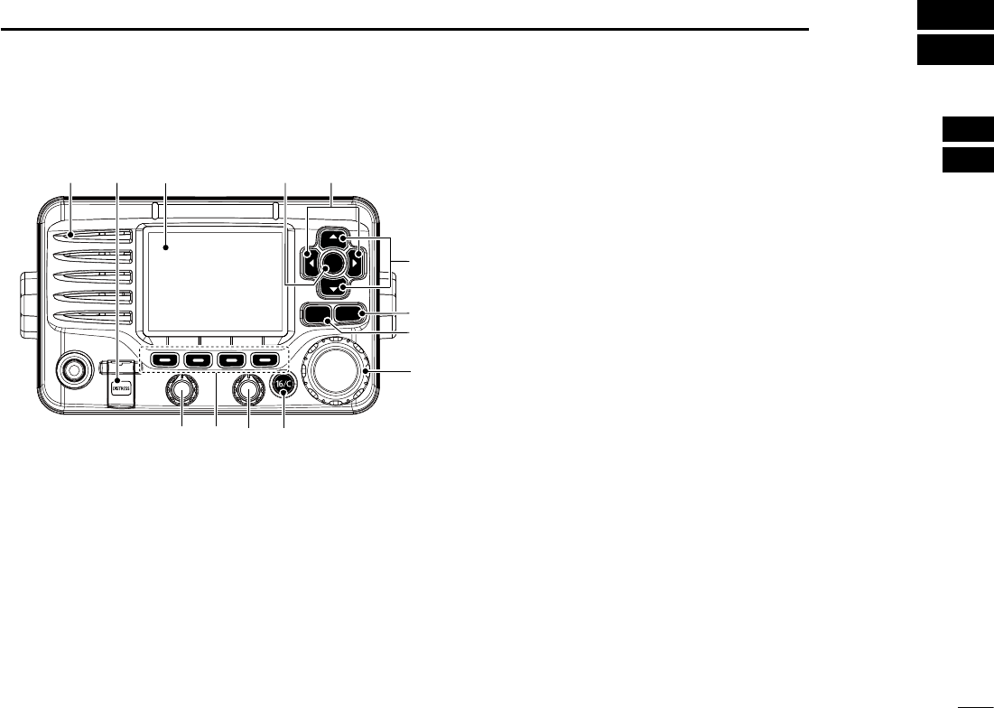
Front panel N
q DISTRESS KEY [DISTRESS] (pp. 23, 24)
Hold down for 3 seconds to transmit a Distress call.
w ENTER KEY [ENT]
Push to set the input data, selected item, and so on.
e LEFT AND RIGHT KEYS [Ω]/[≈]
Push to switch to the previous or next key function that ±
is assigned to the soft keys. (p. 7)
Push to select the desired character or number in the ±
table while in the channel name, position, MMSI code
programming mode, and so on. (pp. 8, 13, 22)
r
UP AND DOWN/CHANNEL SELECT KEYS [∫CH]/[√CH]
Push to select the operating channels, Menu items, ±
Menu settings, and so on.
While scanning, push to check Favorite channels, ±
change the scanning direction or manually resume a
scan. (p. 16)
t CLEAR KEY [CLEAR]
Push to cancel the entered data, or to return to the previ-
ous screen.
y MENU KEY [MENU]
(p.
91
)
Push to enter or exit the Menu screen.
u DIAL/POWER SWITCH [PWR]
When the power is OFF, hold down for 1 second to turn ±
ON power. (p. 11)
± Hold down for 1 second to turn OFF power.
± Rotate to select the operating channels, Menu items,
Menu settings, and so on.
± Push to set the input data, selected item, and so on..
i CHANNEL 16/CALL CHANNEL KEY [16/C]
± Push to select Channel 16. (p. 9)
± Hold down for 1 second to select the Call channel. (p.
9
)
sh#!,,vAPPEARSWHENTHE#ALLCHANNELISSELECTED
CLEARMENU
ENT
CH
CH
t
u
y
we
r
i
q
o
!0!1
Function display (p. 5)
Speaker
3
2PANEL DESCRIPTION
CLEARMENU
ENT
CH
CH
t
u
y
we
r
i
q
o
!0!1
Function display (p. 5)
Speaker
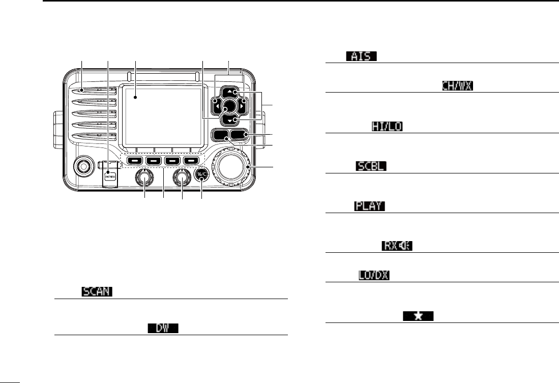
o SQUELCH DIAL
Rotate to adjust the squelch level.
!0 SOFT KEYS
Desired functions as described below can be assigned in
the Menu screen.
Scan [ ] (p. 17)
Push to start or stop a Normal or Priority scan.
Dualwatch/Tri-watch [ ] (p. 18)
Push to start a Dualwatch or Tri-watch. ±
Push to stop a Dualwatch or Tri-watch when either is ±
activated.
AIS [ ] (p. 86)
Push to display AIS plotter on the left side of screen.
Channel/Weather channel [ ]* (pp. 9, 11)
Push to selects and toggles the regular channel and
Weather channel.
High/Low [ ] (p. 11)
Push to set the power to high or low.
s3OMECHANNELSARESETTOONLYLOWPOWER
SCBL [ ] (p. 78)
Push to turn the Voice Scrambler ON or OFF.
s4HE)CONAPPEARSWHENTHEVOICESCRAMBLERIS/.
PLAY [ ] (p. 78)
Push to enter voice recoder menu.
sh2%#v)CONBLINKSWHENTHERECORDERIS/.
RX Speaker [ ] (p. 75)
Push to turn the RX Speaker mode ON or OFF.
LO/DX [ ]* (p. 11)
Push to turn the Attenuator function ON or OFF.
sh,/#vAPPEARSWHENTHE!TTENUATORFUNCTIONIS/.
Favorite channel [ ] (p. 17)
Push to set or clear the displayed channel as a Favorite ±
(Tag) channel.
± Hold down for 3 seconds to clear or set all Favorite
channels in the selected channel group.

4
2
PANEL DESCRIPTION
1
2
3
4
5
6
7
8
9
10
11
12
13
14
15
16
Name [ ] (p. 13)
Push to enter the channel name programming mode.
Backlight [ ] (p. 15)
Push to enter the LCD and key backlight brightness ad-
justment mode.
s7HILEINTHEADJUSTMENTMODEPUSH;∫]/[√]/[Ω]/[≈] or rotate Dial
to adjust the brightness of the LCD and key backlight.
Log [ ] (p. 65)
Push to enter “RCVD CALL LOG” in the DSC CALLS menu.
!1 VOLUME DIAL
Rotate to adjust the volume level.

5
2PANEL DESCRIPTION
Function display N
q BUSY/TRANSMIT ICON (p. 11)
“ ±” appears when receiving a signal or when the
squelch is open.
“ ±” appears while transmitting.
w POWER ICON (p. 11)
“25W” appears when high power is selected. ±
“1W” appears when low power is selected. ±
e RX SPEAKER ICON (p. 75)
Appears while in the RX Speaker mode.
r CHANNEL GROUP ICON (p. 10)
A selected channel group icon, U.S.A. “USA,” Interna- ±
tional “INT” or Canadian “CAN” appears, depending on
the transceiver version.
“WX” appears when the weather channel is selected. ±
t CALL CHANNEL ICON (p. 9)
Appears when the Call channel is selected.
y DUPLEX ICON (p. 10)
Appears when a duplex channel is selected.
u FAVORITE CHANNEL ICON (p. 18)
Appears when a Favorite (Tag) channel is selected.
i MESSAGE ICON
Blinks when there is an unread DSC message.
o GPS ICON
Stays ON when the GPS receiver is activated and valid ±
position data is received.
Blinks when invalid position data is being received. ±
!0 SWITCH ICON (p. 69)
Appears when the “CH 16 SWITCH” in DSC Settings is set
to ‘OFF.’
!1 LOW BATTERY ICON
Blinks when the battery voltage drops to approximately
13 V DC or less.
!4
!6
!7
!5
qwi
et
r!0
you
!1
!2
!3
!8
!9
@0

6
2
PANEL DESCRIPTION
1
2
3
4
5
6
7
8
9
10
11
12
13
14
15
16
!2 CHANNEL NUMBER READOUT
Shows the selected operating channel number.
s7HENASIMPLEXCHANNELISSELECTEDh!vAPPEARS
!3 CHANNEL NAME FIELD
The channel name appears, if programmed. (p. 13)
!4 KEY ICON (p. 7)
Shows the programmed function of the soft keys on the
front panel.
!5 TIME ZONE INDICATOR
Shows the current time when a GPS receiver is con- ±
nected, or the time is manually programmed.
s7HEN THE '03 CURRENT TIME IS INVALIDhv WILL BLINK EVERY
2 seconds instead of the current time. After 23.5 hours has
passed, “NO TIME” will appear.
shv
will
blink every 2 seconds instead of the current time,
after 4 hours have passed from when the time was manually
programmed. The manually programmed time is held for only
23.5 hours, and after that, “NO TIME” will appear.
“LOCAL” appears when the offset time is set. ±
“MNL” appears when ±
the time is manually programmed
.
“UTC” appears when ±
the GGA, GLL or GNS GPS sen-
tence format is included in the GPS signal.
The date information appears when ±
the RMC GPS sen-
tence format is included in the GPS signal.
“NO TIME” appears when no GPS receiver is connect- ±
ed, and no time is manually input.
!6 POSITION INDICATOR
± Shows the current position when a GPS receiver is
connected, or the position is manually programmed.
s7HENTHE'03POSITIONISINVALIDhvMAYBLINKEVERYSEC-
onds instead of position. The last position is held for only
23.5 hours, and after that, “NO POSITION” will appear.
s
hvWILLBLINKEVERYSECONDSINSTEADOFPOSITIONAFTERHOURS
have passed from when the position is manually programmed.
The manually programmed position is held for only 23.5 hours,
and after that, “NO POSITION” will appear.
± “NO POSITION” appears when no GPS receiver is
connected, and no position is manually input.
!7 COURSE INDICATOR
Shows the course of your vessel.
!8 SPEED INDICATOR
Shows the speed of your vessel.
!9 SCAN INDICATOR
“SCAN 16” appears during a Priority scan; “SCAN” ap- ±
pears during a Normal scan. (p. 17)
“DUAL 16” appears during Dualwatch; “TRI 16” appears ±
during Tri-watch. (p. 18)
@0 LOCAL ICON (p. 11)
Appears when the Attenuator function is turned ON.
7
2PANEL DESCRIPTION
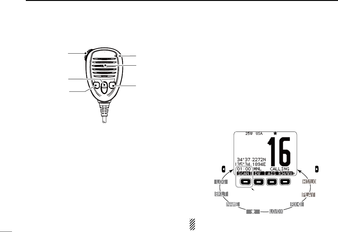
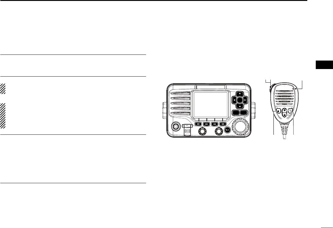
Speaker Microphone N
Microphone
Speaker
w
q
e
r
q PTT SWITCH [PTT]
Hold down to transmit, release to receive. (pp. 11, 12)
w CHANNEL UP/DOWN KEYS [Y]/[Z]
Push either key to check favorite channels, change scan-
ning direction or manually resumes a scan. (pp. 11, 18)
e TRANSMIT POWER KEY [HI/LO]
± Push to toggle the power high or low. (p. 11)
s3OMECHANNELSARESETTOONLYLOWPOWER
± While holding down [HI/LO], turn ON the power to turn
the Microphone Lock function ON or OFF. (p. 14)
r CHANNEL 16/CALL CHANNEL KEY [16/C]
± Push to select Channel 16. (p. 9)
± Hold down for 1 second to select the Call channel. (p.
9
)
sh#!,,vAPPEARSWHENTHE#ALLCHANNELISSELECTED
Soft key function N
Various functions can be assigned to the soft keys. When a
key function is assigned, the key icon is displayed above the
soft key, as shown below. Consult your Icom dealer for de-
tails concerning which functions are pre-programmed into the
keys.
Soft keys are also used for select the icon in the menu screen.
(p. 91)
Soft key function selection D
When “ ±Ω” or “≈” is displayed beside the key icon, pushing
[Ω] or [≈] sequentially shows the previous or next group of
key functions that is assigned to the soft key.
Push Push
*
*Push this key to start
and stop scan.
The order of the key icons may differ, depending on the
preprogramming.
8
3
PREPARATION
1
2
3
4
5
6
7
8
9
10
11
12
13
14
15
16
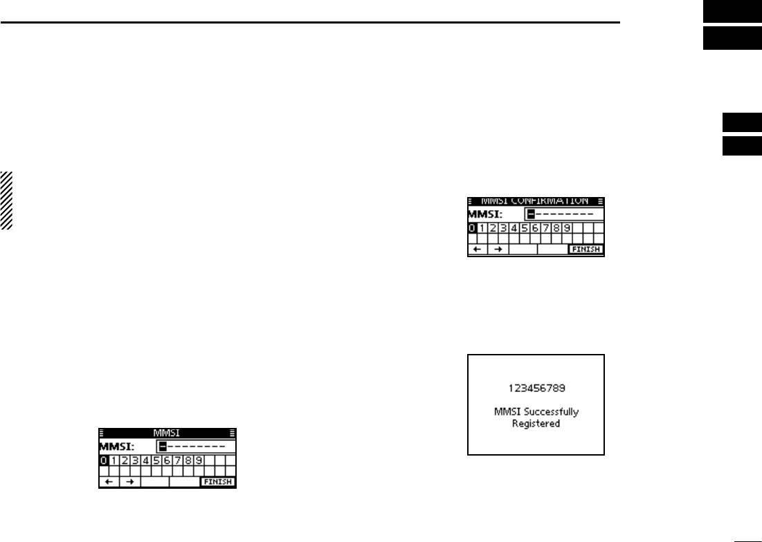
MMSI code programming N
The 9 digit MMSI (Maritime Mobile Service Identity: DSC self
ID) code can be programmed at power ON.
This initial code setting can be performed only once.
After being set, it can be changed by only your dealer
or distributor. If your MMSI code has already been pro-
grammed, this programming is not necessary.
Hold down [PWR](Dial) to turn ON the power. q
s4HREESHORTBEEPSSOUNDANDh./$3#--3)vISDISPLAYED
Push [ENT] to start the MMSI code programming. w
s0USH;#,%!2=TWICETOCANCELTHEPROGRAMMINGANDGOTOTHE
normal operating screen. In this case, the transceiver cannot
make a DSC call. To program the MMSI code, turn OFF the
power, then turn it ON again.
Enter your MMSI code in the following manner: e
s3ELECTADESIREDNUMBERUSING$IALOR;∫]/[√]/[Ω]/[≈].
s0USH;%.4=OR$IALTOSETIT
s4OMOVETHECURSORSELECTEITHERARROWh←” or “→,” then push
[ENT] or Dial.
Repeat step re to enter all 9 digits.
After entering the 9 digit code, “FINISH” is automatically t
selected, and then push [ENT] or Dial to set it.
The “MMSI CONFIRMATION” screen is displayed. y
Enter your MMSI code again for confirmation. u
s%NTERINTHESAMEMANNERASSTEPSe through t.
When your MMSI code programming is successfully com- i
pleted, the screen as shown below is briefly displayed.
s!FTERTHATTHENORMALOPERATINGSCREENISDISPLAYED
The programmed MMSI code can be checked in the MENU
screen. (p. 92)
9
BASIC OPERATION
4
9
Channel selection N
Channel 16 D
Channel 16 is the distress and safety channel. It is used for
establishing initial contact with a station and for emergency
communications. Channel 16 is automatically monitored dur-
ing both Dualwatch and Tri-watch. While standing by, you
must monitor Channel 16.
± Push [16/C] to select Channel 16.
Push [CH/WX]* to return to the screen displayed before you ±
selected Channel 16, or push [∫](CH) or [√](CH) to select
an operating channel.
Call channel D
Each regular channel group has a separate leisure use Call
channel. The Call channels can be programmed, and are
used to store your most often used channel in each channel
group, for quick recall. The Call channel is monitored during
Tri-watch. (p. 13)
Hold down [16/C] for 1 second to select the Call channel of ±
the selected channel group.
sh#!,,vANDTHE#ALLCHANNELNUMBERAPPEAR
s%ACHCHANNELGROUPHASANINDEPENDENTCALLCHANNELAFTERPRO-
gramming. (p. 13)
Push [CH/WX]* to return to the screen displayed before you ±
selected Call channel, or push [∫](CH) or [√](CH) to select
an operating channel.

10
4
BASIC OPERATION
1
2
3
4
5
6
7
8
9
10
11
12
13
14
15
16
Channel group selection D
There are preprogrammed U.S.A. channels, International
channels and Canadian channels. These channel groups
may be specified for the operating area.
q Push [MENU].
w Rotate Dial or push [∫]/[√] to select “Radio Settings,” and
then push [ENT].
e Rotate Dial or push [∫]/[√] to select “CHAN Group,” and
then push [ENT].
r Rotate Dial or push [∫]/[√] to select the desired channel
group, and then push [ENT].
s53!53!)NTERNATIONAL).4AND#ANADIAN#!.CHANNEL
groups can be selected.
t Push [EXIT] to exit the Menu screen.
y Push [∫](CH) or [√](CH) to select a channel.
s0USHING;Y]/[Z] on the microphone selects only Favorite chan-
nels.
sh$50vAPPEARSWHENADUPLEXCHANNELISSELECTED
sh!vAPPEARSWHENASIMPLEXCHANNELISSELECTED
When the International
channel group is selected.
Channel group icon appears
11
4BASIC OPERATION
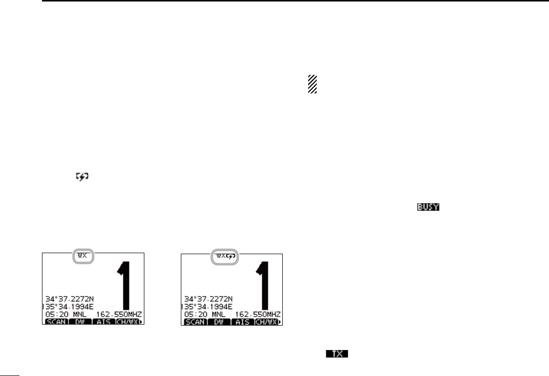
D Weather channels
The transceiver has 10 weather channels. These are used for
monitoring broadcasts from NOAA (National Oceanographic
and Atmospheric Administration.)
The transceiver can automatically detect a weather alert tone
on the selected weather channel or while scanning. (p. 16)
Push [CH/WX] once or twice to select a weather channel. q
sh78vAPPEARSWHENAWEATHERCHANNELISSELECTED
sh78 ” appears when the Weather Alert function is in turned
ON. (p. 78)
Push [ w∫](CH) or [√](CH) to select a channel.
s0USHING;Y]/[Z] on the microphone selects only Favorite chan-
nels.
When weather alert is OFF. When weather alert is ON.
Receiving and transmitting N
#!54)/. Transmitting without an antenna will damage
the transceiver.
Hold down [PWR](Dial) to turn ON the power. q
Set the audio and squelch levels. (p. 15) w
First, open the squelch. Then, adjust the audio output ±
level. After that, adjust the squelch level until the noise
just disappears.
Change the channel group. (p. 10) e
Push [ r∫](CH) or [√](CH) to select a channel. (pp. 9, 10)
s0USHING;Y]/[Z] on the microphone selects only Favorite chan-
nels.
s7HENRECEIVINGASIGNALh ” appears and audio is heard.
s&URTHERADJUSTMENTOFTHEVOLUMELEVELMAYBENECESSARY
Push [LO/DX] to turn the receive Attenuator function ON t
or OFF, if necessary.
s/NLY53!AND!USTRALIANVERSIONTRANSCEIVERS
sh,/#vAPPEARSWHENTHERECEIVE!TTENUATORFUNCTIONIS/.
Push [HI/LO] to select the output power, if necessary. y
sh7vAPPEARSWHENHIGHPOWERISSELECTEDANDh7vAPPEARS
when low power is selected.
s#HOOSELOWPOWERFORSHORTRANGECOMMUNICATIONSCHOOSEHIGH
power for longer distance communications.
s3OMECHANNELSAREFORONLYLOWPOWER
u Hold down [PTT] to transmit, then speak at your normal
voice level.
sh ” appears.
s#HANNELCANNOTBEUSEDFORTRANSMISSIONOTHERTHAN$3#
12
4
BASIC OPERATION
2
3
4
5
6
7
8
9
10
11
12
13
14
15
16
i Release [PTT] to receive.
Information
The Noise Cancel function reduces random noise components
in the transmit and/or receive signal. See page
80
for details.
Simplex channels, 3, 21, 23, 61, 64, 81, 82 and 83 CANNOT
be lawfully used by the general public in U.S.A. waters.
)-0/24!.4 To maximize the readability of your transmit-
ted signal, pause a few seconds after pushing [PTT], hold
the microphone 5 to 10 cm (2 to 4 inches) from your mouth
and speak at a normal voice level.
NOTE for the TOT (Time-out Timer) function
The TOT function inhibits continuous transmission beyond a
preset time period after the transmission starts.
10 seconds before transmission is cutoff, a beep sounds to
indicate the transmission will be shut down and “TOT” appears
in the channel name field. Transmission is not possible for 10
seconds after this shut down.
Microphone
iu
ry
CLEARMENU
ENT
CH
CH
13
4BASIC OPERATION
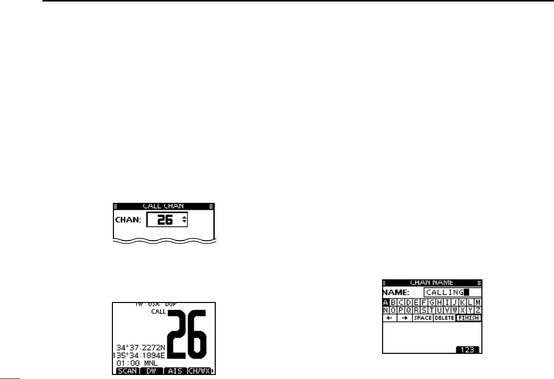
Call channel programming N
You can program the Call channel with your most often-used
channel in each channel group for quick recall.
Select the desired channel group (INT, USA or CAN) to be q
programmed. (p. 10)
w Push [MENU].
e Rotate Dial or push [Ω]/[≈] to select “Radio Settings,” and
then push [ENT].
r Rotate Dial or push [∫]/[√] to select “CALL CHAN,” and
then push [ENT].
t Rotate Dial or push [∫](CH)/[√](CH) to select a channel.
y Push [ENT] to program the displayed channel as the Call
channel.
s0USH;#,%!2=TOCANCEL
Channel name programming N
Each channel can be assigned a unique alphanumeric ID of
up to 10 characters.
Capital letters, 0 to 9, some symbols (! " # $ % & ' ( ) * + , – .
;<=>?ANDASPACECANBEINPUT
Push [ q∫](CH) or [√](CH) to select a channel.
s&IRSTCANCELTHE$UALWATCH4RIWATCHOR 3CAN FUNCTIONIFACTI-
vated.
Push [NAME] to open the channel name programming w
screen.
s!BLACKBOXISDISPLAYEDONTHElRSTCHARACTER
Enter the desired channel name in the following manner: e
s3ELECTADESIREDCHARACTERUSING$IALOR;∫]/[√]/[Ω]/[≈].
s0USH;%.4=TOSETIT
s4OMOVETHECURSORSELECTEITHERARROWh←” or “→,” then push
[ENT].
s3ELECTh30!#%vTHENPUSH;%.4=TOINPUTASPACE
s3ELECTh$%,%4%vTHENPUSH;%.4=TODELETEACHARACTER
s0USH;#,%!2=TOCANCELANDRETURNTOTHEPREVIOUSSCREEN
14
4
BASIC OPERATION
1
2
3
4
5
6
7
8
9
10
11
12
13
14
15
16
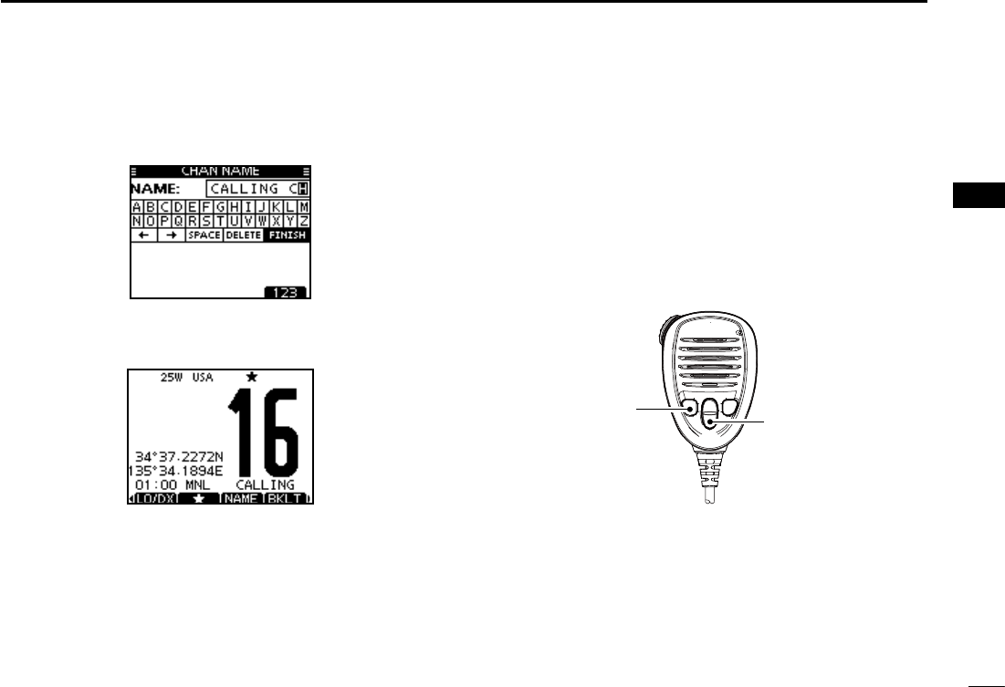
14
Repeat step re to input all characters.
t Push [Ω], [≈], [∫] or [√] to select “FINISH,” then push
[ENT] to set the name and return to the previous screen.
Microphone Lock function N
The Microphone Lock function electrically locks [∫], [√] and
the [HI/LO] keys on the supplied microphone. This prevents
accidental channel changes and function access.
While holding down [HI/LO] on the microphone, hold down ±
[PWR](Dial) to turn ON the transceiver and turn the Micro-
phone Lock function ON or OFF.
[HI/LO] [Y]/[Z]
15
4BASIC OPERATION
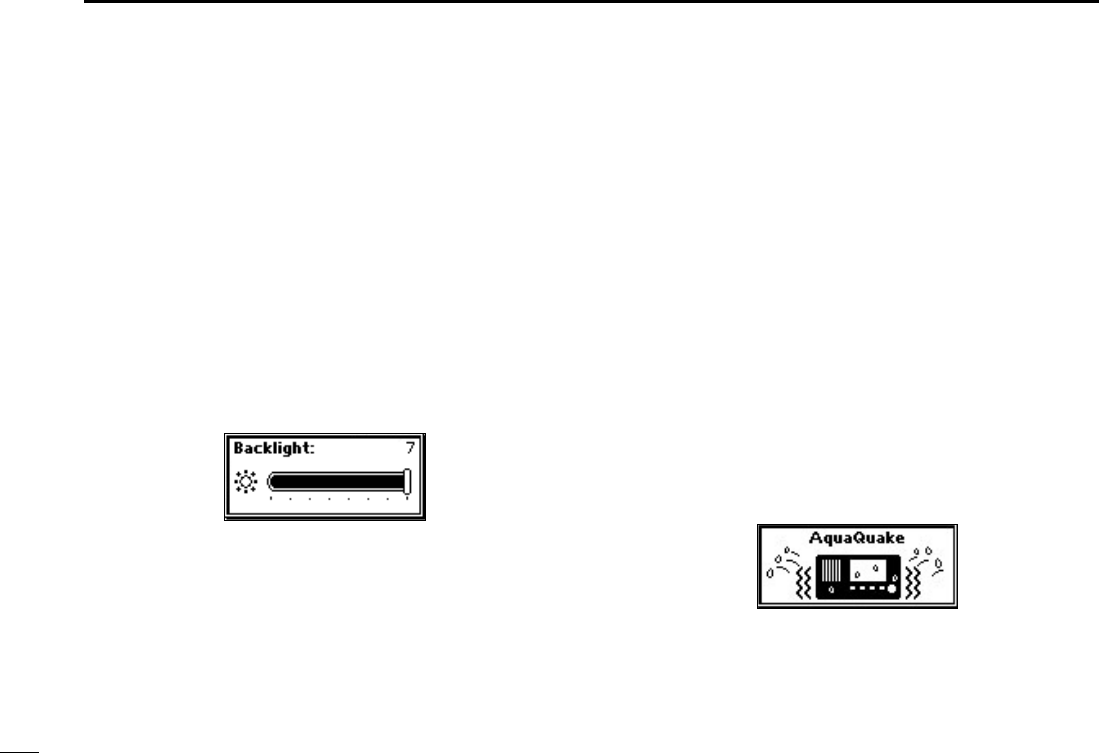
Adjusting the display back- N
light level
The function display and keys can be backlit for better visibil-
ity under low light conditions.
The backlight is adjustable in 7 levels and OFF.
Depending on the preprogramming, the adjustment method
differs, as described below.
Push [BKLT] to show the backlight adjustment screen. Ro- ±
tate Dial to adjust the brightness of the LCD and key back-
light, and then, push [ENT].
s)FNOKEYOPERATIONISPERFORMEDFORABOUTSECONDSTHETRANSCEIVER
sets the selected backlight level, and returns to the normal mode.
AquaQuake water draining N
function
The AquaQuake water draining function clears water away
from the speaker grill. Without this function, water may muffle
the sound coming from the speaker. A buzzing sound is heard
when this function is activated.
q Push [MENU].
w Rotate Dial or push [Ω]/[≈] to select “AQUA QUAKE,” icon
and then push the soft key below the icon.
While holding down [AQUA], the AquaQuake function is ±
activated to clear water away from the speaker grill.
s7HILEHOLDINGDOWN;!15!=ALOWBUZZINGSOUNDSTODRAINWA-
ter, regardless of the volume level setting.
s4HE TRANSCEIVER KEYS EXCEPT ;$)342%33= ARE DISABLED WHILE
the AquaQuake function is activated.
When the AquaQuake function is activated.
16
5
SCAN OPERATION
1
2
3
4
5
6
7
8
9
10
11
12
13
14
15
16
Scan types N
Scanning is an efficient way to locate signals quickly over a
wide frequency range. The transceiver has a Priority scan
and a Normal scan.
When the Weather Alert function is turned ON, the weather
channel is also checked while scanning. (p. 98)
Set the Favorite channels (scanned channel) before scan-
ning. Clear the Favorite channels which inconveniently stop
scanning, such as those for digital communication use. (Refer
to the next page for details.)
Choose Priority or Normal scan in the Menu screen. (p.
97
)
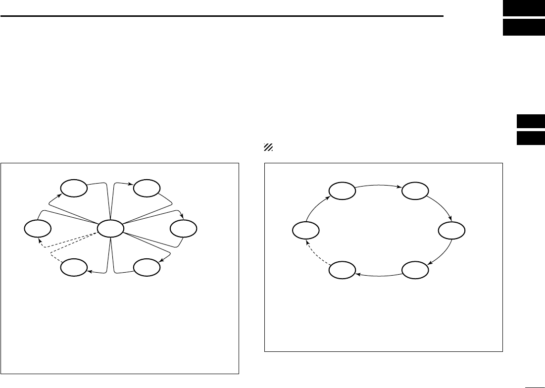
PRIORITY SCAN
The Priority scan sequentially searches through all Favor-
ite channels while monitoring Channel 16. When a signal is
detected on Channel 16, the scan pauses until the signal
disappears. When a signal is detected on a channel other
than Channel 16, the scan becomes a Dualwatch until the
signal disappears.
NORMAL SCAN
The Normal scan, like the Priority scan, sequentially
searches through all Favorite channels. However, unlike
the Priority scan, Channel 16 is not checked unless it is set
as a Favorite channel.
WX*
CH 01
CH 16
CH 02
CH 05 CH 04
CH 03
*When the weather alert function is activated.
CH 01 CH 02
WX*
CH 05 CH 04
CH 03
*When the weather alert function is activated.
17
5SCAN OPERATION
Setting Favorite channels N
For more efficient scanning, add desired channels as Favor-
ite channels, or clear the Favorite on unwanted channels.
Channels that are not tagged will be skipped while scanning.
Favorite channels can be independently assigned to each
channel group (INT, USA, or CAN).
Select the desired channel group. (p. q
10
)
Select the desired channel to be set as a Favorite channel. w
Push [ e] to set the displayed channel as a Favorite channel.
sh” appears on the display.
To cancel the Favorite channel setting, repeat step re.
sh” disappears.
Clearing (or setting) all Favorite channels
Hold down [] for 3 seconds (until a long beep changes to
2 short beeps) to clear all Favorite channel settings in the
selected channel group.
s2EPEATABOVEPROCEDURETOSETALLCHANNELSAS&AVORITECHANNELS
Starting a scan N
First, set the scan type (Priority or Normal scan) and scan
resume timer in the Menu screen. (p. 97)
Select the desired channel group. (p. q
10
)
Set the Favorite channels, as described to the left. w
Make sure the squelch is closed to start a scan. e
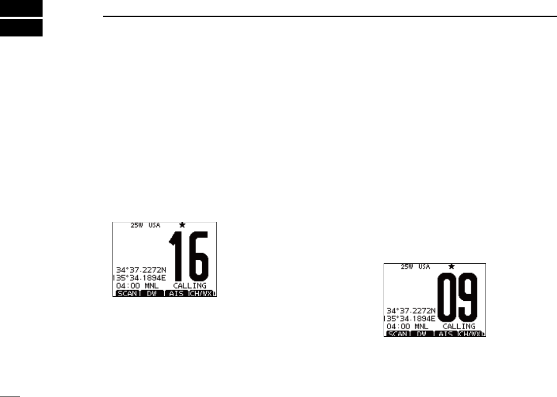
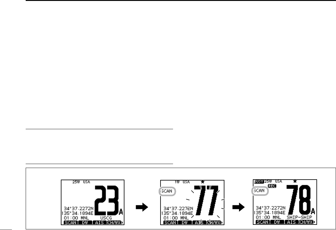
Push [SCAN] to start a Priority or Normal scan. r
sh3#!.vAPPEARSDURINGA0RIORITYSCANh3#!.vAPPEARSDUR-
ing a Normal scan.
s7HENASIGNALISDETECTEDTHESCANPAUSESUNTILTHESIGNALDIS-
appears, or resumes after pausing 5 seconds, depending on the
setting. (Channel 16 is still monitored during a Priority scan.)
s0USH;Y]/[Z] on either transceiver or microphone, to check the
scanning Favorite channels, change the scanning direction or
manually resume the scan.
s!BEEPTONESOUNDSANDhvBLINKSWHENASIGNALISRECEIVEDON
Channel 16 during a Priority scan.
To stop the scan, push [CLEAR] or repeat step tr.
Scan starts. When a signal is received.
Push
[SCAN]
;%XAMPLE= Starting a Normal scan.
18
6
DUALWATCH/TRI-WATCH
1
2
3
4
5
6
7
8
9
10
11
12
13
14
15
16
Description N
Dualwatch monitors Channel 16 while you are receiving
on another channel; Tri-watch monitors Channel 16 and the
Call channel while receiving another channel. Dualwatch and
Tri-watch are convenient for monitoring Channel 16 when you
are operating on another channel.
Operation N
Select Dualwatch or Tri-watch in the Menu screen. (p. 97) q
Push [ wY](CH) or [Z](CH) to select the desired operating
channel.
Push [DW] to start a Dualwatch or Tri-watch scan. e
sh$5!,vAPPEARSDURING$UALWATCHh42)vAPPEARSDURING
Tri-watch.
s!BEEPTONESOUNDSWHENASIGNALISRECEIVEDON#HANNEL
To cancel Dualwatch or Tri-watch, push [DW] again. r
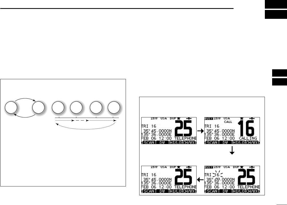
DUALWATCH/TRI-WATCH SIMULATION
Dualwatch Tri-watch
Call channel
Ch 88
Ch 16 Ch 88 Ch 16 Ch 88 Ch 9
s)FASIGNALISRECEIVEDON#HANNEL$UALWATCHAND4RI
watch pause on Channel 16 until the signal disappears.
s)FASIGNALISRECEIVEDONTHE#ALLCHANNELDURING4RIWATCH
Tri-watch becomes Dualwatch until the signal disap-
pears.
s4OTRANSMITONTHESELECTEDCHANNELDURINGA$UALWATCHOR
Tri-watch scan, hold down [PTT].
;%XAMPLE= Operating Tri-watch on INT Channel 25.
Tri-watch starts. Signal is received on
Call channel.
Tri-watch resumes after the
signal disappears.
Signal received on Channel
16 takes priority.
19
DSC OPERATION
7
DSC address ID N
Programming Individual ID D
A total of 100 DSC address IDs can be programmed and as-
signed a name of up to 10 characters.
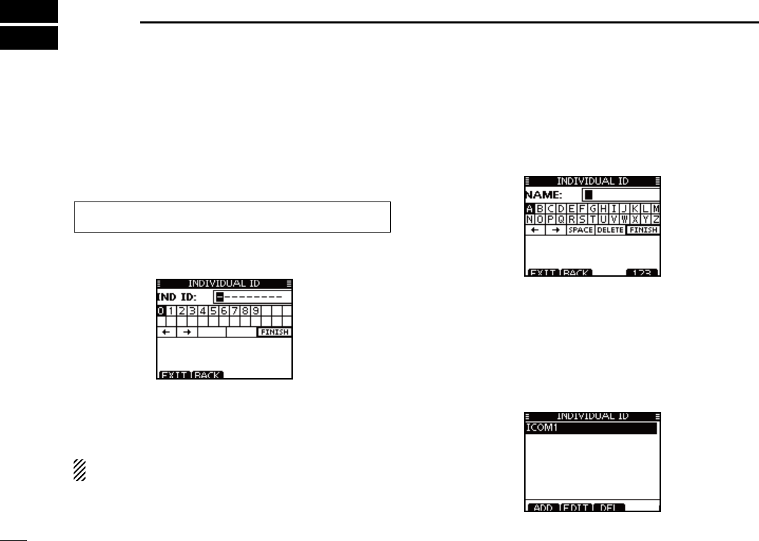
Enter “INDIVIDUAL ID” in the DSC SETTINGS menu. q
Push [ADD]. w
s4HEh).$)6)$5!,)$vPROGRAMSCREENISDISPLAYED
Enter a desired individual ID in the following way: e
s3ELECTADESIREDNUMBERUSING;Y]/[Z]/[Ω]/[≈].
s0USH;%.4=TOSETIT
s4OMOVETHECURSORROTATEDIALORSELECTEITHERARROWh←” or “→,”
then push [ENT].
The first digit is specified as ‘0’ for a Group ID.
The first two digits are ‘0’ for any Coast station ID.
r Repeat step e to enter all 9 digits.
t After entering the 9 digit code, push [ENT] or Dial to set it.
s4HE)$NAMEPROGRAMMINGSCREENISDISPLAYED
y Enter a desired 10 digit ID name in the following way:
s3ELECTADESIREDCHARACTERUSING;Y]/[Z]/[Ω]/[≈].
s0USH;%.4=TOSETIT
s4OMOVETHECURSORROTATEDIALOR select either arrow, “←” or “→,”
then push [ENT].
s0USH;=THEN;=THEN;!"#=TOSELECTACHARACTERGROUP
u After entering the ID name, select “FINISH” using [Y]/[Z]/
[Ω]/[≈], then push [ENT] to program it.
s4HEh).$)6)$5!,)$vLISTSCREENISDISPLAYED
i Push [MENU] to exit the MENU screen.
eMENUf ¶ eDSC SETf ¶ e
Individual ID
f
(Push [MENU]) (Select icon)
(Rotate Dial, then push [ENT].)
20
7
DSC OPERATION
1
2
3
4
5
6
7
8
9
10
11
12
13
14
15
16
D Programming Group ID
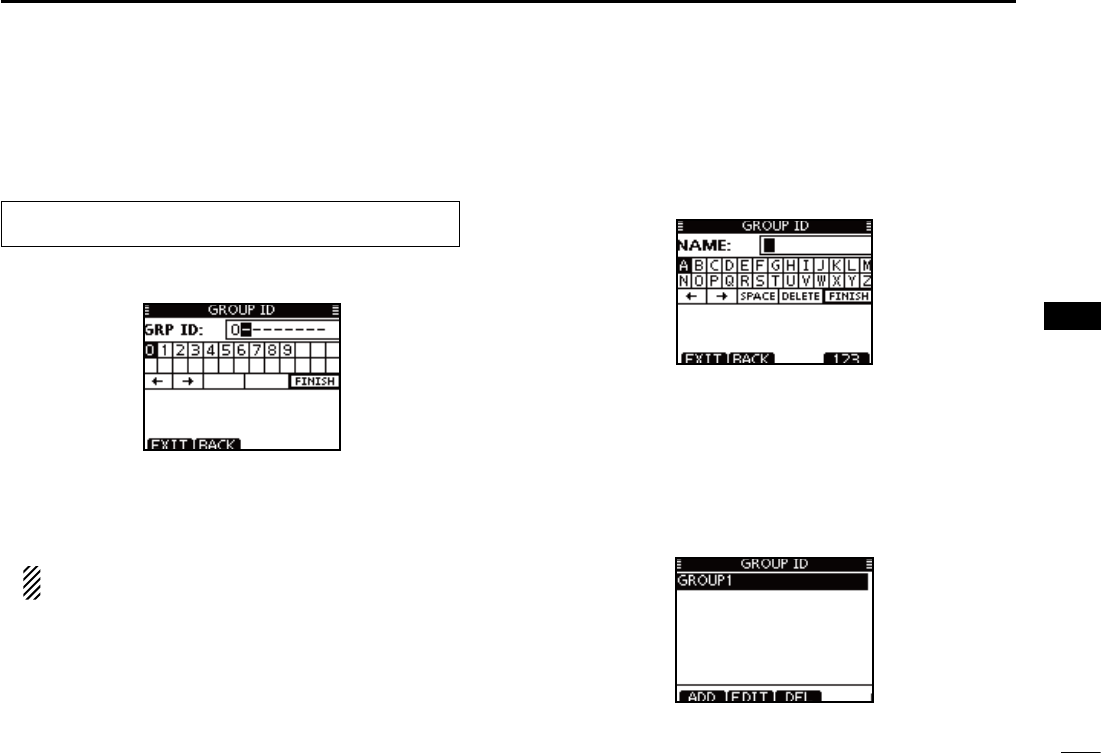
Enter “GROUP ID” in the DSC SETTINGS menu. q
Push [ADD]. w
s4HEh'2/50)$vPROGRAMSCREENISDISPLAYED
e Enter a desired group ID in the following way:
s3ELECTADESIREDNUMBERUSING;Y]/[Z]/[Ω]/[≈].
s0USH;%.4=TOSETIT
s4OMOVETHECURSORROTATEDIALORSELECTEITHERARROWh←” or “→,”
then push [ENT].
The first digit is fixed as ‘0’ for a Group ID.
The first two digits are ‘0’ for any Coast station ID.
r Repeat step e to input the specific 9 digits group code.
t After entering the 9 digit code, push [ENT] or Dial to set it.
s4HE'ROUP)$NAMEPROGRAMMINGSCREENISDISPLAYED
Enter a desired 10 digit ID name in the following way: y
s3ELECTADESIREDCHARACTERUSING;Y]/[Z]/[Ω]/[≈].
s0USH;%.4=TOSETIT
s4OMOVETHECURSORROTATEDIALOR select either arrow, “←” or “→,”
then push [ENT].
s0USH;=THEN;=THEN;!"#=TOSELECTACHARACTERGROUP
After entering the ID name, select “FINISH” using dial or u
[Y]/[Z]/[Ω]/[≈], then push [ENT] or Dial to program it.
s4HEh'2/50)$vLISTSCREENISDISPLAYED
i Push [MENU] to exit the MENU screen.
eMENUf ¶ eDSC SETf ¶ e
Group ID
f
(Push [MENU]) (Select icon)
(Rotate Dial, then push [ENT].)
21
7DSC OPERATION
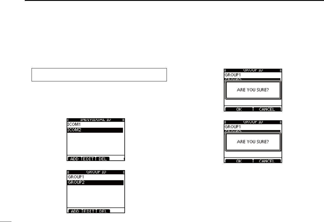
D Deleting Individual/Group ID
q Enter “INDIVIDUAL ID” or “GROUP ID” in the DSC SET-
TINGS menu.
s7HENNOADDRESS)$ISPROGRAMMEDh.O)$vISDISPLAYED)NTHIS
case, push [MENU] to exit the MENU screen.
w Rotate Dial or push [Y]/[Z] to select a desired ID name,
then push [DEL].
e Push [OK] to delete the ID, and return to the “INDIVIDUAL
ID” or “GROUP ID” list screen.
s0USH;#!.#%,=TOCANCELIT
r Push [MENU] to exit the MENU screen.
eMENUf ¶ eDSC SETf ¶ e
Individual ID
f/e
Group ID
f
(Push [MENU]) (Select icon)
(Rotate Dial, then push [ENT].)
22
7
DSC OPERATION
1
2
3
4
5
6
7
8
9
10
11
12
13
14
15
16
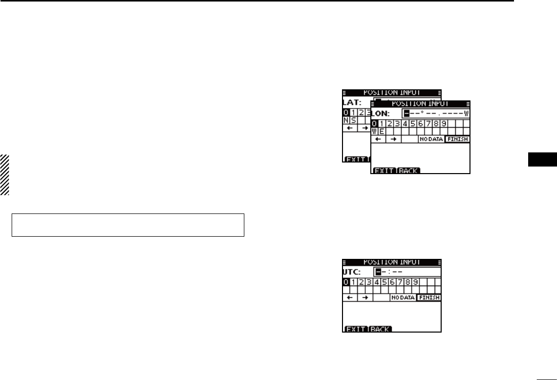
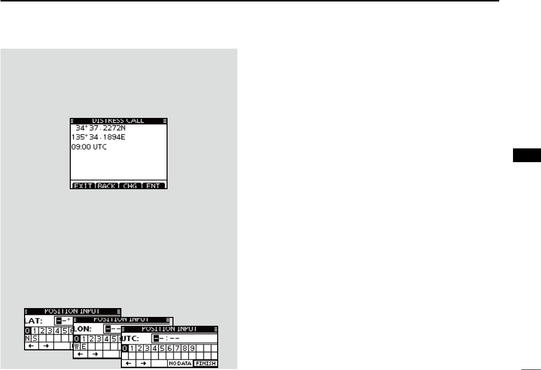
A Distress call should include the ship’s position and time.
If no GPS is connected, your position and UTC (Universal
Time Coordinated) time should be manually input. They are
automatically included when a GPS receiver compatible with
the NMEA0183 ver. 2.0 or 3.01 or NMEA 2000 format is con-
nected.
s-ANUALPROGRAMMINGISDISABLEDWHENA'03RECEIVERIS
connected.
s-ANUALLYPROGRAMMEDPOSITIONANDTIMEWILLBEHELDFOR
only 23.5 hours.
q Enter “POSITION INPUT” in the DSC SETTINGS menu.
Edit your latitude and longitude position using Dial, or [ wY]/
[Z]/[Ω]/[≈].
s3ELECTADESIREDNUMBERUSING;Y]/[Z]/[Ω]/[≈].
s0USH;%.4=TOSETIT
s4OMOVETHECURSORROTATEDIALORSELECTEITHERARROWh←” or “→,”
then push [ENT].
s3ELECT..ORTHLATITUDEOR33OUTHLATITUDEWHENTHECURSORIS
on the ‘N’ or ‘S’ position.
s3ELECT77ESTLONGITUDEOR%%ASTLONGITUDEWHENTHECURSOR
is on the ‘W’ or ‘E’ position.
After entering the position, push [ENT] to program it. e
The UTC time programming screen is displayed, enter the r
UTC time in the following way:
s3ELECTADESIREDNUMBERUSING;Y]/[Z]/[Ω]/[≈].
s0USH;%.4=TOSETIT
s4OMOVETHECURSORROTATEDIALORSELECTEITHERARROWh←” or “→,”
then push [ENT].
Push [ENT] or Dial to program your position and time. t
s2ETURNTOTHEh$3#3%44).'3vSCREEN
Position and time programming N
eMENUf ¶ eDSC SETf ¶ ePosition Inputf
(Push [MENU]) (Select icon)
(Rotate Dial, then push [ENT].)
23
7DSC OPERATION
Distress call N
A Distress call should be transmitted if, in the opinion of the
Master, the ship or a person is in distress and requires im-
mediate assistance.
NEVER MAKE A DISTRESS CALL IF YOUR SHIP OR A
PERSON IS NOT IN AN EMERGENCY. A DISTRESS
CALL SHOULD BE MADE ONLY WHEN IMMEDIATE
HELP IS NEEDED.
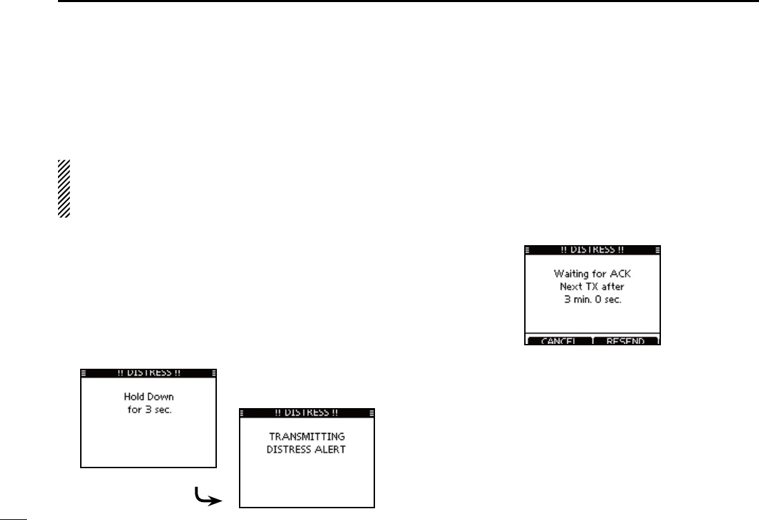
Simple call D
Confirm no Distress call is being received. q
While lifting up the key cover, hold down [DISTRESS] for 3 w
seconds to transmit the Distress call.
s7HILEHOLDINGDOWN;$)342%33=COUNTDOWNBEEPSSOUNDAND
both the key and display backlighting blink.
s$3# CHANNEL #HANNEL IS AUTOMATICALLY SELECTED AND THE
Distress call is transmitted.
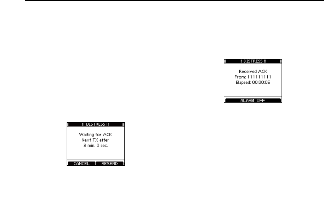
After transmitting the call, the transceiver waits for an ac- e
knowledgment call.
s4HE $ISTRESS CALL IS AUTOMATICALLY TRANSMITTED EVERY TO
minutes, until an acknowledgement is received (‘Call repeat’
mode), or DSC Cancel call is made. (p. 27)
s0USH;2%3%.$=TOMANUALLYTRANSMITTHE$ISTRESSREPEATCALL
s0USH ;Ω]/[≈] then push [INFO] to display the transmitted Dis-
tress call information.
s0USH;Ω]/[≈] then push [PAUSE] to pause the ‘Call repeat’ mode,
push [RESUME COUNTDOWN] to resume it.
After receiving the acknowledgment, push [ALARM OFF] r
then reply using the microphone.
A distress alert default contains: ±
s.ATUREOFDISTRESS 5NDESIGNATEDDISTRESS
s0OSITIONINFORMATION4HE LATEST '03 OR MANUAL INPUT POSITION
is held for 23.5 hours, or until the power is
turned OFF.
24
7
DSC OPERATION
1
2
3
4
5
6
7
8
9
10
11
12
13
14
15
16
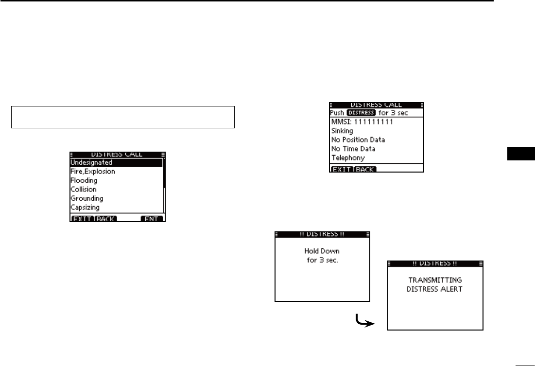
D Regular call
The nature of the Distress call should be included in the Dis-
tress call.
Enter “DISTRESS CALL” in the DSC menu. q
w Select the nature of the distress using Dial or [Y]/[Z], then
push Dial or [ENT].
s@5NDESIGNATED@&IRE%XPLOSION@&LOODING@#OLLISION@'ROUNDING
‘Capsizing,’ ‘Sinking,’ ‘Adrift,’ ‘Abandoning ship,’ ‘Piracy’ or ‘Man
Overboard’ is selectable.
s4HENATUREOFTHEDISTRESSISSTOREDFORMINUTESAFTERASELEC-
tion is made.
e The Distress call confirmation screen is displayed.
s2OTATE$IALORPUSH;Y]/[Z] to see the hidden lines.
r Hold down [DISTRESS] for 3 seconds to transmit the Dis-
tress call.
s7HILEHOLDINGDOWN;$)342%33=COUNTDOWNBEEPSSOUNDAND
both the key and display backlighting blink.
s4HESELECTEDNATUREOFTHEDISTRESSISSTOREDFORMINUTES
eMENUf ¶ eDSCf ¶ eDistress Callf
(Push [MENU]) (Select icon)
(Rotate Dial, then push [ENT].)
25
7DSC OPERATION
t After transmitting the call, the transceiver waits for an ac-
knowledgment call.
s4HE $ISTRESS CALL IS AUTOMATICALLY TRANSMITTED EVERY TO
minutes, until an acknowledgement is received (‘Call repeat’
mode), or DSC cancel call is made. (p. 27)
s0USH;2%3%.$=TOMANUALLYTRANSMITTHE$ISTRESSREPEATCALL
s0USH ;Ω]/[≈] then push [INFO] to display the transmitted Dis-
tress call information.
s0USH;Ω]/[≈] then push [PAUSE] to pause the ‘Call repeat’ mode,
push [RESUME COUNTDOWN] to resume it.
y After receiving an acknowledgment call, push [ALARM
OFF] then reply using the microphone.
± A distress alert contains:
s.ATUREOFDISTRESS 3ELECTEDINSTEPw.
s0OSITIONINFORMATION4HE LATEST '03 OR MANUAL INPUT POSITION
is held for 23.5 hours, or until the power is
turn
y After receiving an acknowledgment call, push [ALARM
OFF] then reply using the microphone.
± A distress alert contains:
s.ATUREOFDISTRESS 3ELECTEDINSTEPw.
s0OSITIONINFORMATION4HE LATEST '03 OR MANUAL INPUT POSITION
is held for 23.5 hours, or until the power is
turned OFF.
26
7
DSC OPERATION
1
2
3
4
5
6
7
8
9
10
11
12
13
14
15
16
When no GPS receiver is connected, and both position and
time have been manually programmed, the screen as shown
below appears. Edit your latitude and longitude position and
UTC time as follows:
Push [CHG], then edit your latitude and longitude position ±
and UTC time.
s3ELECTADESIREDNUMBERUSING;Y]/[Z]/[Ω]/[≈].
s0USH;%.4=OR$IALTOSETIT
s4OMOVETHECURSORSELECTEITHERARROWh←” or “→,” then push
[ENT] or Dial.
s3ELECT..ORTHLATITUDEOR33OUTHLATITUDEWHENTHECURSORIS
on the ‘N’ or ‘S’ position.
s3ELECT77ESTLONGITUDEOR%%ASTLONGITUDEWHENTHECURSOR
is on the ‘W’ or ‘E’ position.
27
7DSC OPERATION
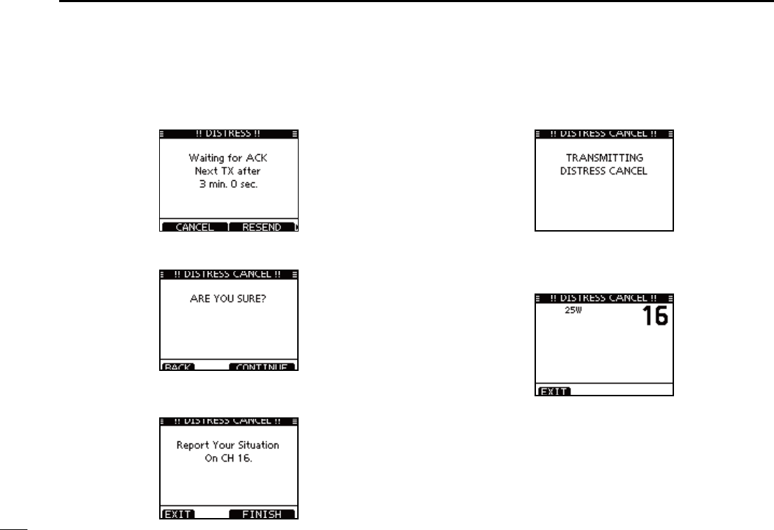
D Distress cancel call
While waiting for an acknowledgment call, push [CAN- q
CEL].
Push [CONTINUE]. w
s0USH;"!#+=TORETURNTOWAITINGFORANACKNOWLEDGEMENTCALL
e Push [FINISH].
s0USH;%8)4=TORETURNTOWAITINGFORANACKNOWLEDGEMENTCALL
r The Distress cancel call is transmitted.
t Channel 16 is automatically selected.
s2EPORTYOURSITUATIONUSINGTHEMICROPHONE
s!FTERTHEREPORTPUSH ;%8)4=TORETURNTO THENORMALOPERATING
mode.
28
7
CHAPTER CONTINUED
1
2
3
4
5
6
7
8
9
10
11
12
13
14
15
16
Transmitting DSC calls N
To ensure correct operation of the DSC function, make
sure you correctly set the CH70 SQL Level. (p. 71)
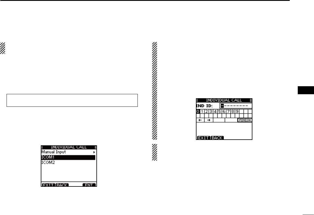
Transmitting an individual call D
The Individual call function allows you to transmit a DSC sig-
nal to only a specific station.
Enter “INDIVIDUAL CALL” in the DSC CALLS menu. q
eMENUf ¶ eDSCf ¶ eIndividual Callf
(Push [MENU]) (Select icon)
(Rotate Dial, then push [ENT].)
Select the desired pre-programmed individual address, or w
“Manual Input,” using Dial or [Y]/[Z], then push [ENT].
s4HE)$CODEFORTHE)NDIVIDUALCALLCANBESETlRSTP
s7HENh-ANUAL)NPUTvISSELECTEDSETADESIREDDIGIT--3))$
code for the individual you wish to call.
About Manual Inputting:
Enter a desired individual ID in the following way:
s3ELECTADESIREDNUMBERUSING;Y]/[Z]/[Ω]/[≈].
s0USH;%.4=TOSETIT
s4OMOVETHECURSORROTATEDIALOR select either arrow, “←” or “→,”
then push [ENT].
s4HElRSTDIGITISSPECIlEDAS@FORA'ROUP)$)FA'ROUP)$IS
entered, an error beep sounds after pushing [FINISH].
s4HElRSTTWODIGITSARE@FORANYCOASTSTATION)$
./4% When a coast station is selected in step w, the
voice channel is automatically specified by the coast sta-
tion. Therefore, skip step r and go directly to step t.
29
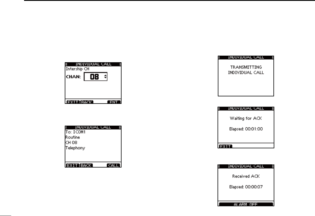
7DSC OPERATION
e Select a desired intership channel using Dial or [Y](CH)/
[Z](CH), then push [ENT].
s)NTERSHIPCHANNELSAREALREADYPRESETINTOTHETRANSCEIVERINTHE
recommended order.
r A confirmation screen appears.
s#ONlRMTHECALLCONTENTS
t Push [CALL] to transmit the Individual call.
s)F#HANNELISBUSYTHETRANSCEIVERSTANDSBYUNTILTHECHANNEL
becomes clear.
y Standby on Channel 70 until an acknowledgement is re-
ceived.
i When the acknowledgement ‘Able to comply’ is received,
beeps sound and the screen below is displayed.
30
7
CHAPTER CONTINUED
1
2
3
4
5
6
7
8
9
10
11
12
13
14
15
16
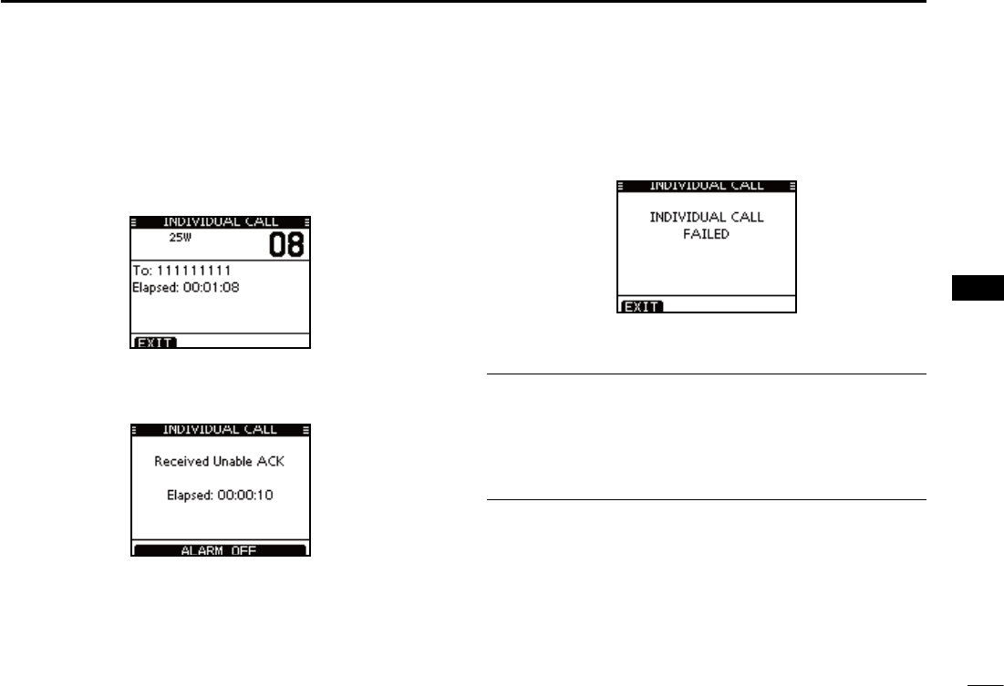
Push [ALARM OFF] to stop the beeps and then select the
intership channel specified in step r.
s!DIFFERENTINTERSHIPCHANNELWILLBESELECTEDIF THE STATION YOU
called cannot use the channel.
s2EPLYUSINGTHEMICROPHONE!NDGOTOSTEPo.
Or, when the acknowledgement ‘Unable to comply’ is re-
ceived, beeps sound and the screen below is displayed.
Push [ALARM OFF] to stop the beeps. Then push [EXIT]
to return to the operating channel (before you entered the
MENU screen).
After communicating, push [EXIT] to return to the normal o
operating mode.
Convenient!
When the optional MA-500TR
CLASS B AIS TRANSPONDER
is
connected to your transceiver, you can transmit individual
DSC calls to selected AIS targets on the transponder without
needing to enter the target’s MMSI code.
See pages
70
and
84
for more details.
31
7DSC OPERATION
Transmitting an Individual Acknowledgement D
When receiving an Individual call, you can transmit an ac-
knowledgement (‘Able to Comply,’ ‘Propose New Channel’ or
‘Unable to Comply’) by using the on-screen prompts (Quick
ACK.) Also, you can send an acknowledgement through the
MENU system (Man ual ACK.)
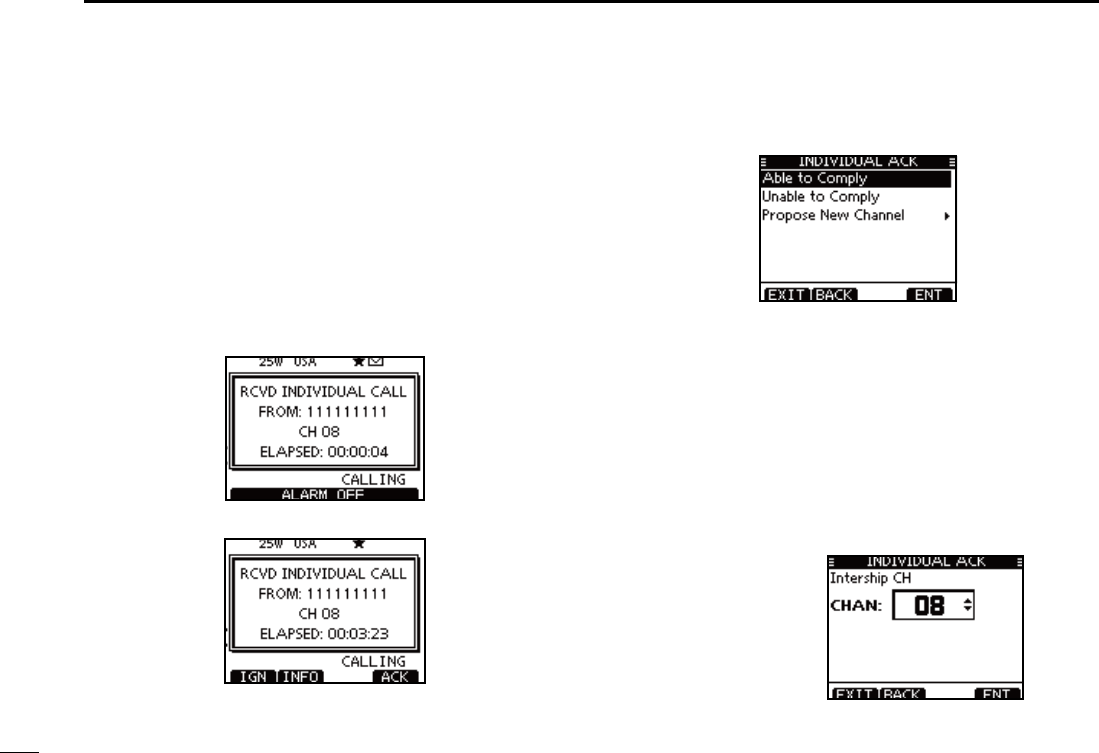
Quick ACK:
When an Individual call is received, beeps sound and the q
screen below is displayed.
Push [ALARM OFF] to stop the beeps.
Push [ACK]. w
Select one of three options, then push [ENT]. e
s!BLETO#OMPLY -AKEANACKNOWLEDGMENTCALLWITHOUT
any changes.
s5NABLETO#OMPLY 9OUCANNOTMAKEACOMMUNICATION
The Acknowledgement call (‘Unable to
Comply’) can be automatically trans-
mitted, if set. See page 66 for details.
s0ROPOSE.EW#HANNEL 9OU CAN MAKE AN ACKNOWLEDGEMENT
call, but you specify the intership chan-
nel. Select a desired intership channel,
using dial, or [Y](CH)/[Z](CH), then
push [ENT].
32
7
CHAPTER CONTINUED
1
2
3
4
5
6
7
8
9
10
11
12
13
14
15
16
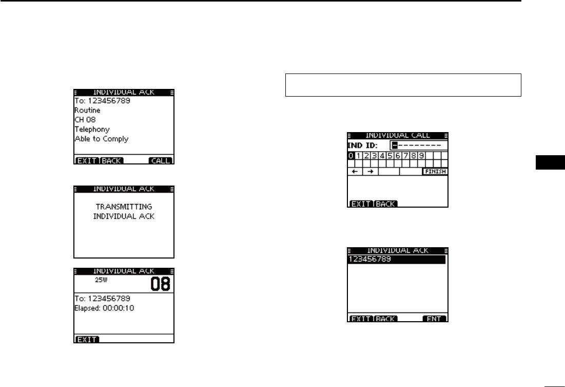
The Individual ACK confirmation screen is displayed. r
Push [CALL] to transmit an acknowledgement call.
The screens shown below are displayed. t
Reply to the call using the microphone. y
Push [EXIT] to return to the normal operating mode. u
Manual ACK:
Enter “INDIVIDUAL ACK” in the DSC CALLS menu. q
eMENUf ¶ eDSCf ¶ eIndividual ACKf
(Push [MENU]) (Select icon)
(Rotate Dial, then push [ENT].)
s7HENNO)NDIVIDUALCALLHASBEENRECEIVEDh)NDIVIDUAL!#+vITEM
will not be displayed.
Select a desired individual address or ID code to reply to, w
using Dial or [Y]/[Z], then push [ENT].
Perform steps ee to u, as described in “Quick ACK:,” be-
ginning on the previous page.
33
7DSC OPERATION
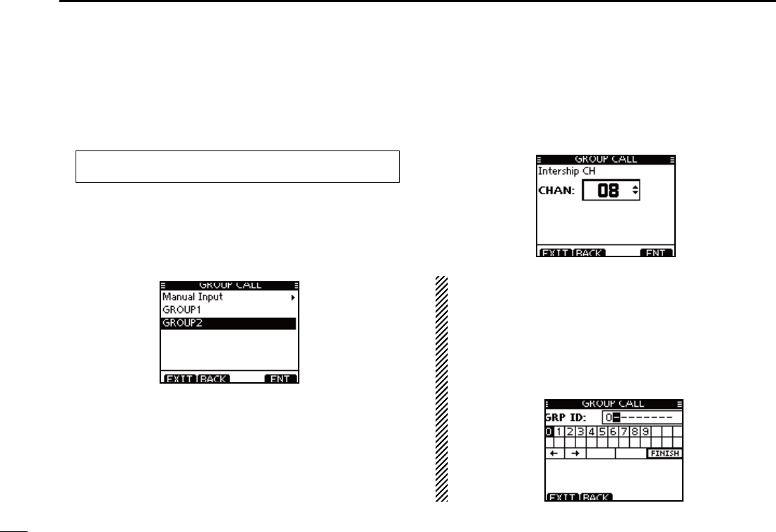
Transmitting a Group call D
The Group call function allows you to transmit a DSC signal
to only a specific group.
Enter “GROUP CALL” in the DSC CALLS menu. q
eMENUf ¶ eDSCf ¶ eGroup Callf
(Push [MENU]) (Select icon)
(Rotate Dial, then push [ENT].)
Select the desired pre-programmed group address or w
“Manual Input,” using Dial or [Y]/[Z], then push [ENT].
s4HE)$CODEFORTHE'ROUPCALLCANBESETlRSTP
s7HENh-ANUAL)NPUTvISSELECTEDSETTHEDIGIT)$CODEFORTHE
group you wish to call.
e Select a desired intership channel using Dial or [Y](CH)/
[Z](CH), then push [ENT].
s)NTERSHIPCHANNELSAREALREADYPRESETINTOTHETRANSCEIVERINTHE
recommended order.
About Manual Inputting:
Enter a desired group ID in the following way:
s3ELECTADESIREDNUMBERUSING;Y]/[Z]/[Ω]/[≈].
s0USH;%.4=OR$IALTOSETIT
s4OMOVETHECURSORROTATEDIALOR select either arrow, “←” or “→,”
then push [ENT].
s4HElRSTDIGITISSPECIlEDAS@FORA'ROUP)$
s4HElRSTTWODIGITSARE@FORANY#OASTSTATION)$
34
7
DSC OPERATION
1
2
3
4
5
6
7
8
9
10
11
12
13
14
15
16
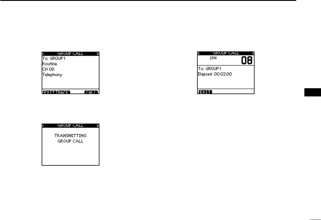
r A confirmation screen appears.
s#ONlRMTHECALLCONTENTS
Push [CALL] to transmit the Group call. t
s)F#HANNELISBUSYTHETRANSCEIVERSTANDSBYUNTILTHECHANNEL
becomes clear.
After the Group call has been transmitted, the following y
screen is displayed.
Announce the information using the microphone. u
After the announcement, push [EXIT] to return to the nor- i
mal operating mode.
35
7DSC OPERATION
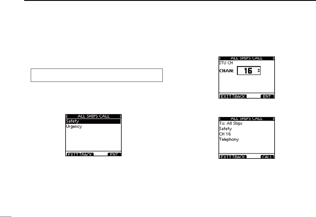
Transmitting an All Ships call D
All ships, that have DSC transceiver, use Channel 70 as their
‘listening channel.’ When you want to announce a message to
these ships within range, use the ‘All Ships Call’ function.
Enter “ALL SHIPS CALL” in the DSC CALLS menu. q
eMENUf ¶ eDSCf ¶ eAll Ships Callf
(Push [MENU]) (Select icon)
(Rotate Dial, then push [ENT].)
Select a desired category, using Dial or [ wY]/[Z], then push
[ENT].
s4HE SELECTABLE CATEGORY MAY DIFFER DEPENDING ON THE PRO-
grammed setting. Ask your dealer for the selectable categories.
Select a desired traffic channel, using Dial or [ eY]/[Z], then
push [ENT].
s4HESELECTEDCHANNELISDISPLAYED
r A confirmation screen appears.
s#ONlRMTHECALLCONTENTS

36
7
DSC OPERATION
1
2
3
4
5
6
7
8
9
10
11
12
13
14
15
16
t Push [CALL] to transmit the All Ships call.
s)F#HANNELISBUSYTHETRANSCEIVERSTANDSBYUNTILTHECHANNEL
becomes clear.
After the All Ships call has been transmitted, the following y
screen is displayed.
Announce the message using the microphone. u
After the announcement, push [EXIT] to return to the nor- i
mal operating mode.
37
7DSC OPERATION
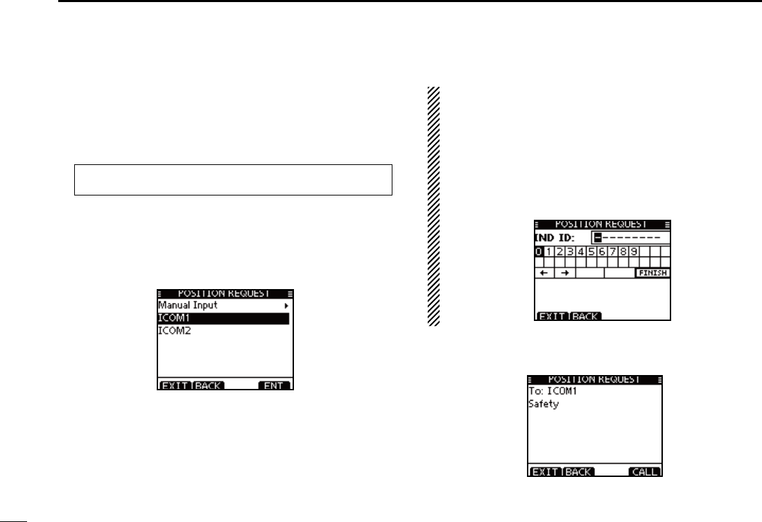
D Transmitting a Position Request Call
(U.S.A. and Australian version transceiver only)
Transmit a Position Request Call when you want to know a
specific ship’s current position, etc.
Enter “POSITION REQUEST” in the DSC CALLS menu. q
eMENUf ¶ eDSCf ¶ ePosition Requestf
(Push [MENU]) (Select icon)
(Rotate Dial, then push [ENT].)
Select the desired pre-programmed individual address, or w
“Manual Input,” using Dial or [Y]/[Z], then push [ENT].
s4HE)$CODEFORTHE0OSITION2EQUEST#ALLCANBESETlRSTP
s7HENh-ANUAL)NPUTvISSELECTEDSETADESIREDDIGIT--3))$
code for the individual you wish to call.
About Manual Inputting:
Enter a desired individual ID in the following way:
s3ELECTADESIREDNUMBERUSING$IALOR;Y]/[Z]/[Ω]/[≈].
s0USH;%.4=OR$IALTOSETIT
s4OMOVETHECURSORSELECTEITHERARROWh←” or “→,” then push
[ENT] or Dial.
s4HElRSTDIGITISSPECIlEDAS@FORA'ROUP)$)FA'ROUP)$IS
entered, an error beep sounds after pushing [FINISH].
s4HElRSTTWODIGITSARE@FORANYCOASTSTATION)$
e A confirmation screen appears.
s#ONlRMTHECALLCONTENTS
38
7
DSC OPERATION
1
2
3
4
5
6
7
8
9
10
11
12
13
14
15
16
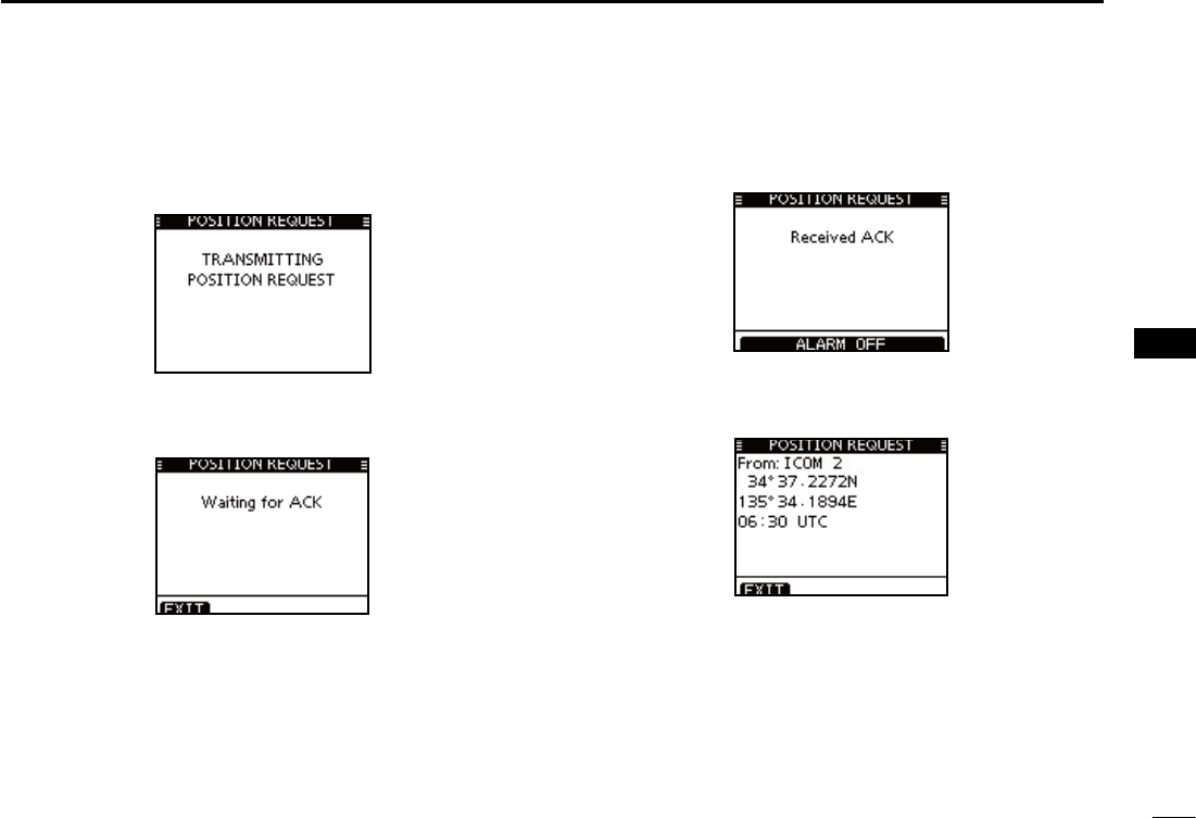
Push [CALL] to transmit the Position Request Call. r
s)F#HANNELISBUSYTHETRANSCEIVERSTANDSBYUNTILTHECHANNEL
becomes clear.
After the Position Request Call has been transmitted, the t
following screen is displayed.
When the acknowledgement call is received, beeps sound y
and the following screen is displayed.
u Push [ALARM OFF] to stop the beeps, and then the screen
as shown below is displayed.
Push [EXIT] to return to the normal operating mode. i
39
7DSC OPERATION
D Transmitting a Position Report Call
Transmit a Position Report Call when you want to announce
your own position to a specific ship and receive an answer
back.
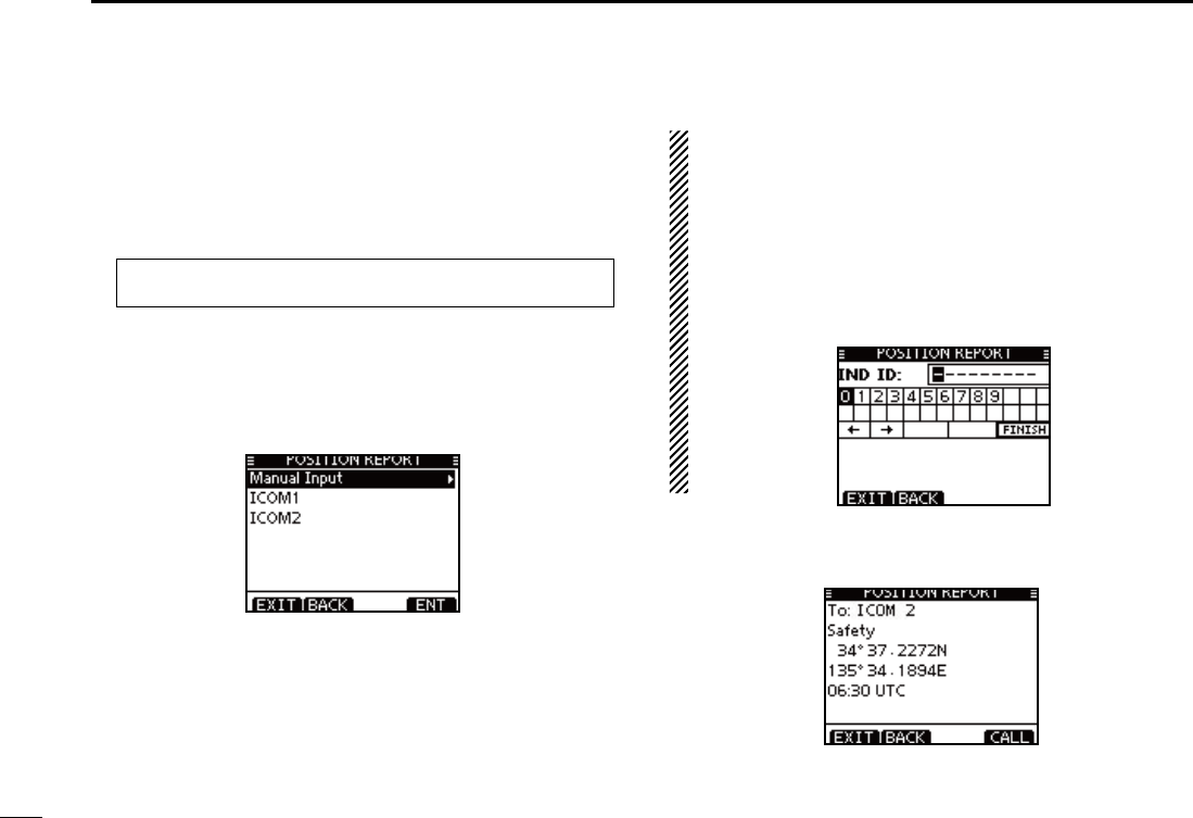
Enter “POSITION REPORT” in the DSC CALLS menu. q
eMENUf ¶ eDSCf ¶ ePosition Reportf
(Push [MENU]) (Select icon)
(Rotate Dial, then push [ENT].)
Select the desired pre-programmed individual address, or w
“Manual Input,” using Dial or [Y]/[Z], then push [ENT].
s4HE)$CODEFORTHE)NDIVIDUALCALLCANBESETlRSTP
s7HENh-ANUAL)NPUTvISSELECTEDSETADESIREDDIGIT--3))$
code for the individual you wish to call.
About Manual Inputting:
Enter a desired individual ID in the following way:
s3ELECTADESIREDNUMBERUSING$IALOR;Y]/[Z]/[Ω]/[≈].
s0USH;%.4=ORTOSETIT
s4OMOVETHECURSORSELECTEITHERARROWh←” or “→,” then push
[ENT] or Dial.
s4HElRSTDIGITISSPECIlEDAS@FORA'ROUP)$)FA'ROUP)$IS
entered, an error beep sounds after pushing [FINISH].
s4HElRSTTWODIGITSARE@FORANYCOASTSTATION)$
A confirmation screen appears. e
s#ONlRMTHECALLCONTENTS
40
7
DSC OPERATION
1
2
3
4
5
6
7
8
9
10
11
12
13
14
15
16
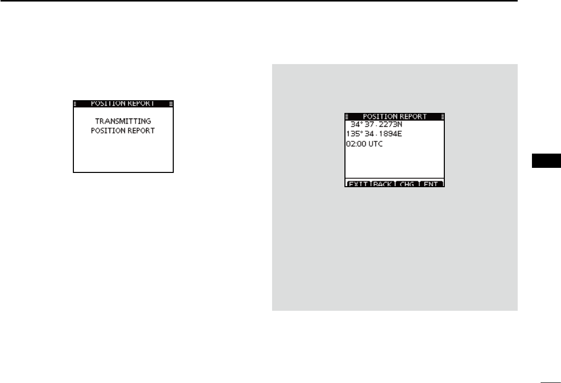
Push [CALL] to transmit the Position Report Call. r
s)F#HANNELISBUSYTHETRANSCEIVERSTANDSBYUNTILTHECHANNEL
becomes clear.
After the Position Report Call has been transmitted, the t
transceiver automatically returns to the normal operating
mode.
When no GPS receiver is connected, and both position and
time have been manually programmed, the screen shown
below appears. Edit your latitude and longitude position and
UTC time as follows:
Push [CHG], then edit your latitude and longitude position ±
and UTC time.
s3ELECTADESIREDNUMBERUSING$IALOR;Y]/[Z]/[Ω]/[≈].
s0USH;%.4=OR$IALTOSETIT
s4OMOVETHECURSORSELECTEITHERARROWh←” or “→,” then push
[ENT] or Dial.
s3ELECT..ORTHLATITUDEOR33OUTHLATITUDEWHENTHECURSOR
is on the ‘N’ or ‘S’ position.
s3ELECT77ESTLONGITUDEOR%%ASTLONGITUDEWHENTHECUR-
sor is on the ‘W’ or ‘E’ position.
41
7DSC OPERATION
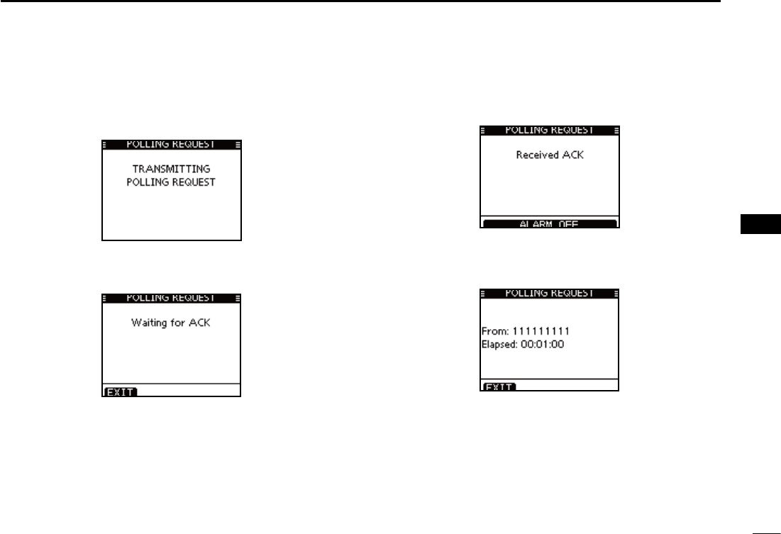
Transmitting a Polling Request Call D
Transmit a Polling Request Call when you want to know a
specific vessel is in the communication area, or not.
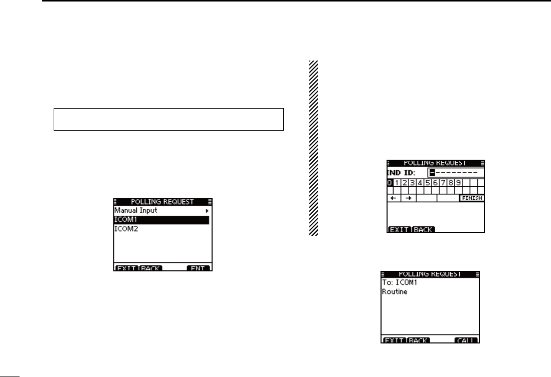
Enter “POLLING REQUEST” in the DSC CALLS menu. q
eMENUf ¶ eDSCf ¶ ePolling Requestf
(Push [MENU]) (Select icon)
(Rotate Dial, then push [ENT].)
Select the desired pre-programmed individual address, or w
“Manual Input,” using Dial or [Y]/[Z], then push [ENT].
s4HE)$CODEFORTHE)NDIVIDUALCALLCANBESETlRSTP
s7HENh-ANUAL)NPUTvISSELECTEDSETADESIREDDIGIT--3))$
code for the individual you wish to call.
About Manual Inputting:
Enter a desired individual ID in the following way:
s3ELECTADESIREDNUMBERUSING$IALOR;Y]/[Z]/[Ω]/[≈].
s0USH;%.4=TOSETIT
s4OMOVETHECURSORSELECTEITHERARROWh←” or “→,” then push
[ENT] or Dial.
s4HElRSTDIGITISSPECIlEDAS@FORA'ROUP)$)FA'ROUP)$IS
entered, an error beep sounds after pushing [FINISH].
s4HElRSTTWODIGITSARE@FORANYCOASTSTATION)$
A confirmation screen appears. e
s#ONlRMTHECALLCONTENTS
42
7
DSC OPERATION
1
2
3
4
5
6
7
8
9
10
11
12
13
14
15
16
Push [CALL] to transmit the Polling Request Call. r
s)F#HANNELISBUSYTHETRANSCEIVERSTANDSBYUNTILTHECHANNEL
becomes clear.
After the Polling Request Call has been transmitted, the t
following screen is displayed.
When the acknowledgement call is received, beeps sound y
and the following screen is displayed.
Push [ALARM OFF] to stop the beeps, and then the screen u
as shown below is displayed.
Push [EXIT] to return to the normal operating mode. i
43
7DSC OPERATION
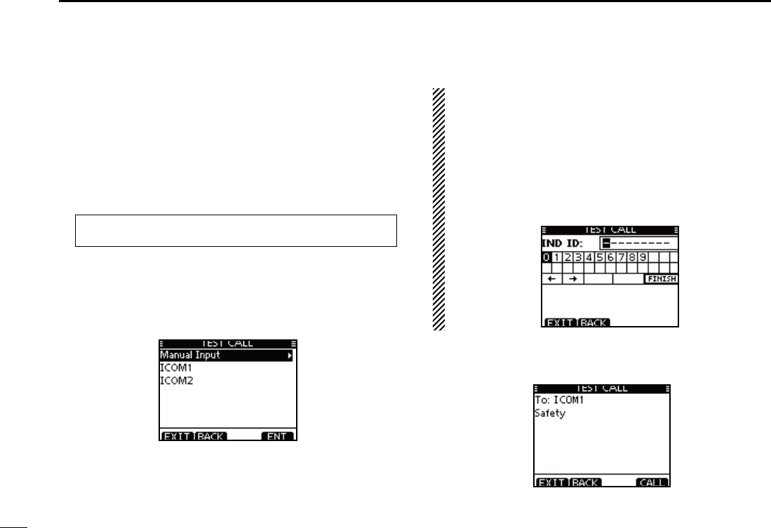
D Transmitting a Test call
Testing on the exclusive DSC distress and safety calling chan-
nels should be avoided as much as possible. When testing on
a distress/safety channel is unavoidable, you should indicate
that these are test transmissions.
Normally the test call would require no further communica-
tions between the two stations involved.
Enter “TEST CALL” in the DSC CALLS menu. q
eMENUf ¶ eDSCf ¶ eTest Callf
(Push [MENU]) (Select icon)
(Rotate Dial, then push [ENT].)
Select a desired pre-programmed individual address, or w
“Manual Input,” then push Dial or [ENT].
s4HE)$CODEFORTHE)NDIVIDUALCALLCANBESETlRSTP
s7HENh-ANUAL)NPUTvISSELECTEDSETTHEDIGIT--3))$CODEFOR
the individual you wish to call.
About Manual Inputting:
Enter a desired address ID in the following way:
s3ELECTADESIREDNUMBERUSING$IALOR;Y]/[Z]/[Ω]/[≈].
s0USH;%.4=OR$IALTOSETIT
s4OMOVETHECURSORSELECTEITHERARROWh←” or “→,” then push
[ENT] or Dial.
s4HElRSTDIGITISSPECIlEDAS@FORA'ROUP)$)FA'ROUP)$IS
entered, an error beep sounds after pushing [FINISH].
s4HElRSTTWODIGITSARE@FORANY#OASTSTATION)$
e A confirmation screen appears.
s#ONlRMTHECALLCONTENTS
44
7
DSC OPERATION
1
2
3
4
5
6
7
8
9
10
11
12
13
14
15
16
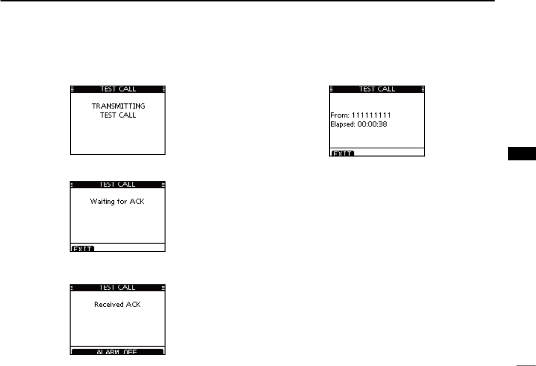
Push [CALL] to transmit the Test call. r
s)F#HANNELISBUSYTHETRANSCEIVERSTANDSBYUNTILTHECHANNEL
becomes clear.
After the Test call has been transmitted, the following t
screen is displayed.
y When the acknowledgement call is received, beeps sound
and the following screen is displayed.
Push [ALARM OFF] to stop the beeps, and then the screen u
as shown below is displayed.
i Push [EXIT] to return to the normal operating mode.
45
7DSC OPERATION
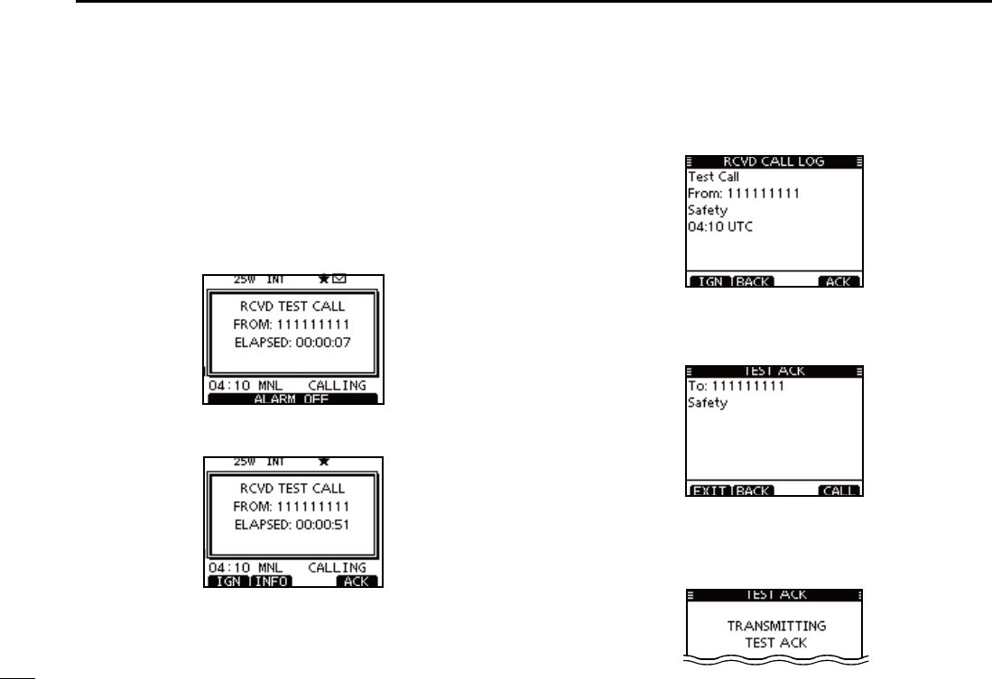
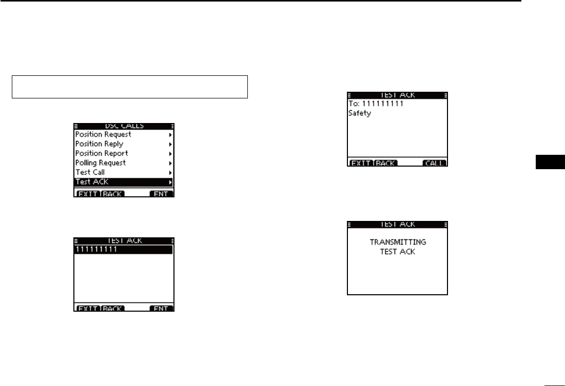
D Transmitting a Test Acknowledgement call
When the “TEST ACK” in DSC settings is set to ‘Auto’
(p. 68), the transceiver automatically transmits a reply call
when receiving a Test call.
Quick ACK:
When a Test call is received, beeps sound and the screen q
shown below is displayed.
Push [ALARM OFF] to stop the beeps.
Push [ACK]. w
s0USH;).&/=TODISPLAYTHE4ESTCALLINFORMATION
Push [BACK] to return to the previous screen, or push [ACK].
The Test ACK confirmation screen is displayed. e
Push [CALL] to transmit the acknowledgement call.
r While transmitting the acknowledgement call, the screen
shown below is displayed, and then returns to the normal
operating mode.
46
7
DSC OPERATION
1
2
3
4
5
6
7
8
9
10
11
12
13
14
15
16
Manual ACK:
Enter “TEST ACK” in the DSC CALLS menu. q
eMENUf ¶ eDSCf ¶ eTest ACKf
(Push [MENU]) (Select icon)
(Rotate Dial, then push [ENT].)
s)FNO4ESTCALLHASBEENRECEIVEDTHEh4%34!#+vITEMWILLNOT
be displayed.
w Select a desired Test call to reply to, using Dial or [Y]/[Z],
then push [ENT].
e The Test ACK confirmation screen is displayed.
Push [CALL] to transmit the acknowledgement call.
r While transmitting the acknowledgement call, the screen
shown below is displayed, and then returns to the normal
operating mode.
47
7DSC OPERATION
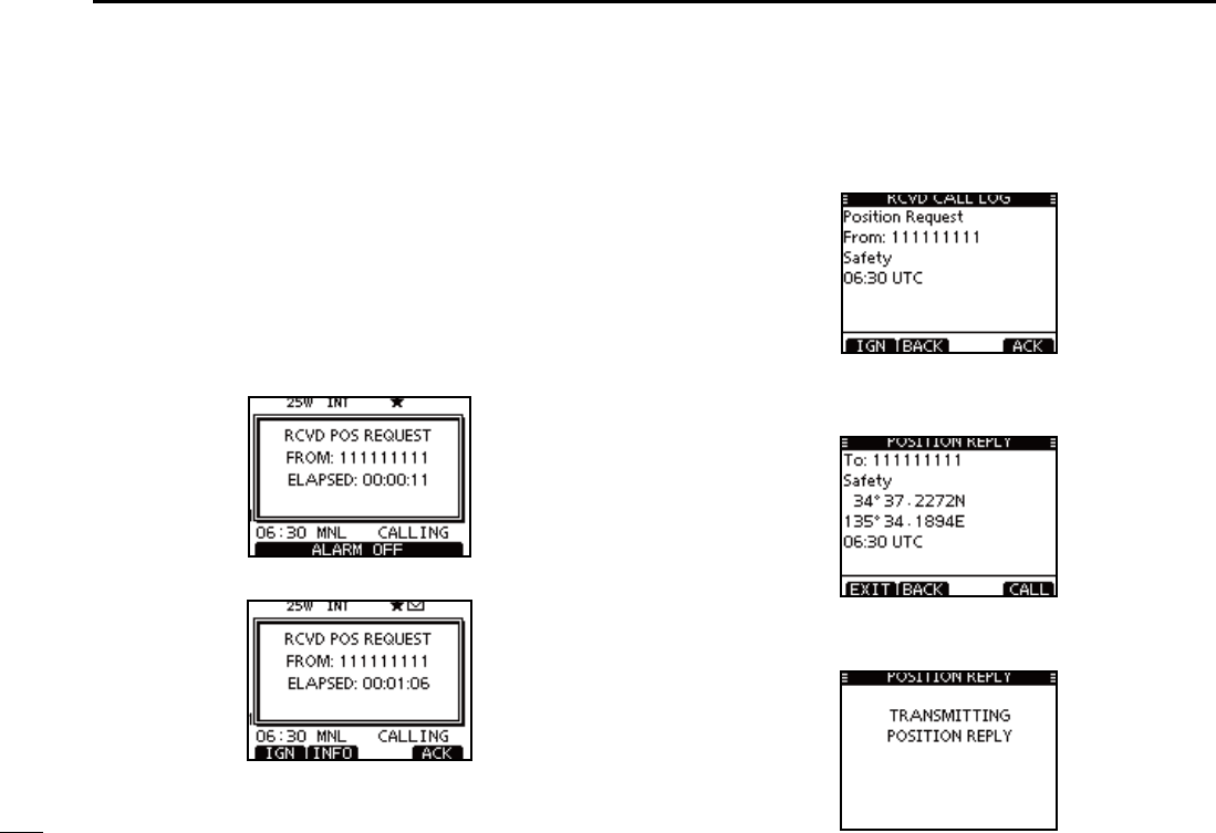
Transmitting a Position Reply call D
Transmit a Position Reply call when a Position Request call
is received.
When the “POSITION ACK” in DSC Settings is set to ‘Auto’
(p. 68), the transceiver automatically transmits a reply call
when receiving a Position Request call.
Quick Reply:
When a Position Request call is received, beeps sound q
and the screen shown below is displayed.
Push [ALARM OFF] to stop the beeps.
w Push [ACK].
s0USH;).&/=TODISPLAYTHE0OSITION2EQUESTCALLINFORMATION
Push [BACK] to return to the previous screen, or push [ACK].
The Position Reply confirmation screen is displayed. e
Push [CALL] to transmit the reply call.
While transmitting the reply call, the screen shown below r
is displayed, and then returns to the normal operating
mode.
48
7
DSC OPERATION
1
2
3
4
5
6
7
8
9
10
11
12
13
14
15
16
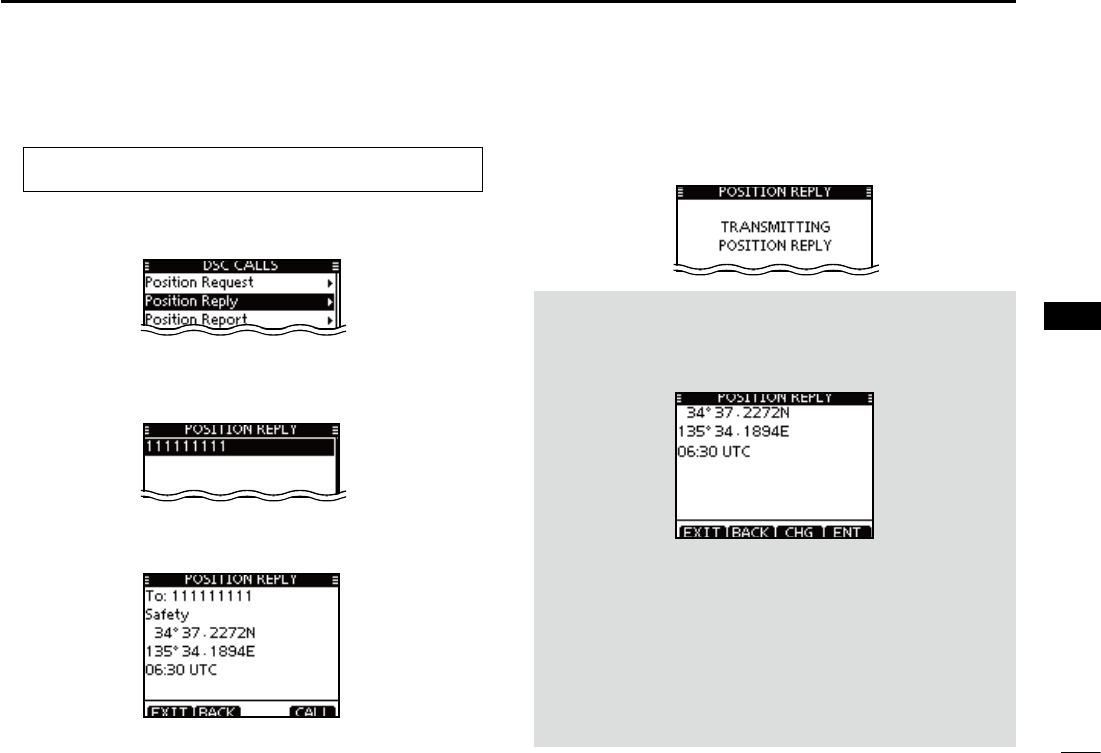
Manual Reply:
Enter “POSITION REPLY” in the DSC CALLS menu. q
eMENUf ¶ eDSCf ¶ ePosition Replyf
(Push [MENU]) (Select icon)
(Rotate Dial, then push [ENT].)
s)FNO0OSITION2EQUESTCALLHASBEENRECEIVEDTHEh0/3)4)/.
REPLY” item will not be displayed.
Select a desired Position Request call to reply to, using w
Dial or [Y]/[Z], then push [ENT].
e The Position Reply call confirmation screen is displayed.
Push [CALL] to transmit the acknowledgement call.
r While transmitting the reply call, the screen shown below
is displayed, and then returns to the normal operating
mode.
When no GPS receiver is connected, and both position and
time have been manually programmed, the screen shown
below appears. Edit your latitude and longitude position and
UTC time as follows:
Push [CHG], then edit your latitude and longitude position ±
and UTC time.
s3ELECTADESIREDNUMBERUSING$IALOR;Y]/[Z]/[Ω]/[≈].
s0USH;%.4=OR$IALTOSETIT
s4OMOVETHECURSORSELECTEITHERARROWh←” or “→,” then push
[ENT] or Dial.
s3ELECT..ORTHLATITUDEOR33OUTHLATITUDEWHENTHECURSOR
is on the ‘N’ or ‘S’ position.
s3ELECT77ESTLONGITUDEOR%%ASTLONGITUDEWHENTHECUR-
sor is on the ‘W’ or ‘E’ position.
49
7DSC OPERATION
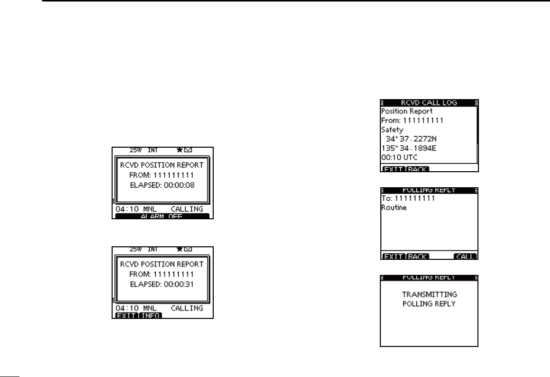
D Transmitting a Position Report Reply call
Transmit a Position Report Reply call when a Position Report
call is received.
Quick Reply:
When a Position Report call is received, beeps sound and q
the screen as shown below is displayed.
Push [ALARM OFF] to stop the beeps.
s0USH;).&/=TODISPLAYTHE0OSITION2EPORT2EQUESTCALLINFORMA-
tion.
Push [BACK] to return to the previous screen.
50
7
DSC OPERATION
1
2
3
4
5
6
7
8
9
10
11
12
13
14
15
16
Manual Reply:
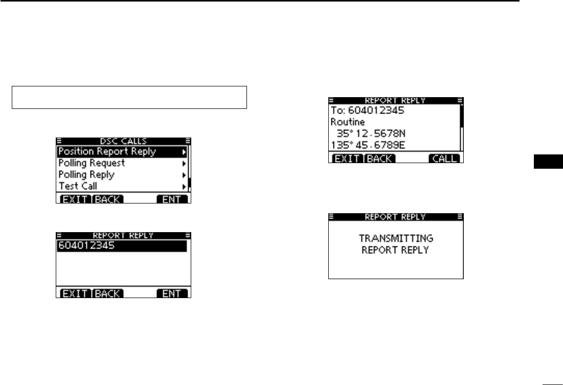
Enter “POSITION REPORT REPLY” in the DSC CALLS q
menu.
eMENUf ¶ eDSCf ¶ ePosition Report Replyf
(Push [MENU]) (Select icon)
(Rotate Dial, then push [ENT].)
s)FNO0OSITION2EPORT2EQUESTCALLHASBEENRECEIVEDTHEh0/3)-
TION REPORT REPLY” item will not be displayed.
Select a desired Position Report Request call to reply to, w
using Dial or [Y]/[Z], then push [ENT].
The Position Report Reply call confirmation screen is dis- e
played.
Push [CALL] to transmit the acknowledgement call.
While transmitting the reply call, the screen shown below r
is displayed, and then returns to the normal operating
mode.
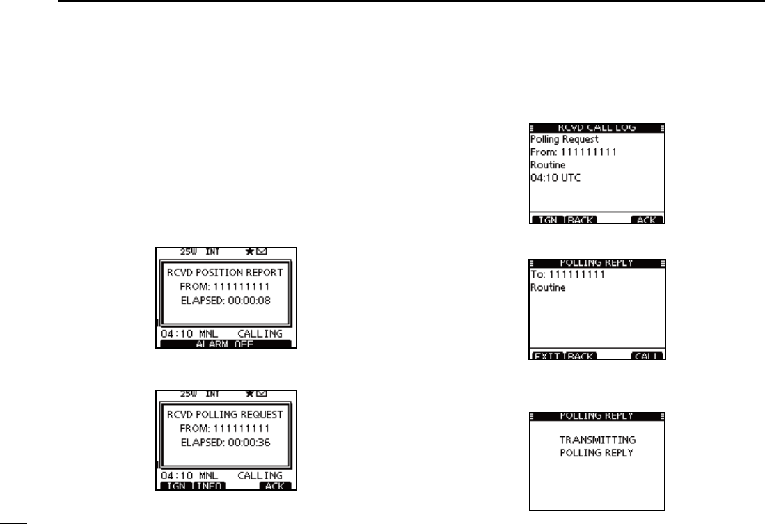
51
7DSC OPERATION
Transmitting a Polling Reply call D
Transmit a Polling Reply call when a Polling Request call is
received.
When the “POSITION ACK” in DSC Settings is set to ‘Auto’
(p. 66), the transceiver automatically transmits a reply call
when receiving a Polling Request call.
Quick Reply:
When a Polling Request call is received, beeps sound and q
the screen as shown below is displayed.
Push [ALARM OFF] to stop the beeps.
Push [ACK]. w
s0USH;).&/=TODISPLAYTHE0OLLING2EQUESTCALLINFORMATION
Push [BACK] to return to the previous screen, or push [ACK].
The Polling Reply confirmation screen is displayed. e
Push [CALL] to transmit the reply call.
While transmitting the reply call, the screen shown below r
is displayed, and then returns to the normal operating
mode.
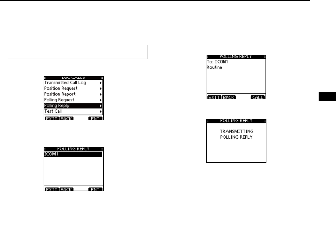
52
7
DSC OPERATION
1
2
3
4
5
6
7
8
9
10
11
12
13
14
15
16
Manual Reply:
Enter “POLLING REPLY” in the DSC CALLS menu. q
eMENUf ¶ eDSCf ¶ ePolling Replyf
(Push [MENU]) (Select icon)
(Rotate Dial, then push [ENT].)
s)FNO0OLLING2EQUESTCALLHASBEENRECEIVEDTHEh0/,,).'2%-
PLY” item will not be displayed.
Select a desired Polling Request call to be replied, using w
Dial or [Y]/[Z], then push [ENT].
e
The Polling Reply call confirmation screen is displayed.
Push [CALL] to transmit the acknowledgement call.
r While transmitting the reply call, the screen shown below
is displayed, and then returns to the normal operating
mode.
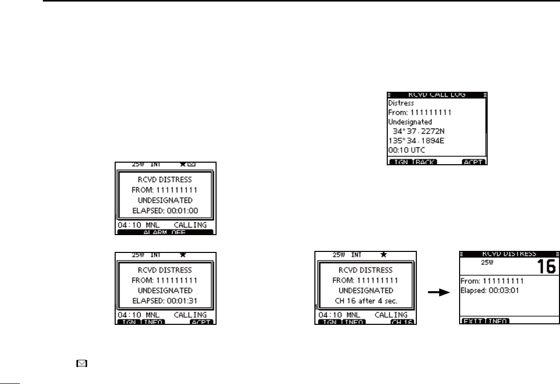
53
7DSC OPERATION
Receiving DSC calls N
Receiving a Distress Call D
When a Distress Call is received:
The emergency alarm sounds for 2 minutes. ±
“ RCVD DISTRESS” pops up and the LCD backlight ±
blinks.
q Push [ALARM OFF] to stop the alarm and the blinking
backlight.
w Push a soft key to select your desired action.
[IGN]
±Push to return to the normal operating mode.
s4HETRANSCEIVEREXITSTHE$3#MODE
s"YPUSHING;044=THETRANSCEIVERALSOEXITSTHE$3#MODE
sh ” continues to blink and the Call is stored in the Received
Call Log.
[INFO]
±Push to display the Received call information. (p. 65)
[ACPT]
Push to accept the call. ±
And then, push [CH 16] to switch the operating channel
to Channel 16, and then monitor it, as a coast station
may require assistance.
s)FYOUHAVENTPUSHED;#(=WITHINSECONDSTHEOPERAT-
ing channel automatically switches to Channel 16. (p. 69)
Push
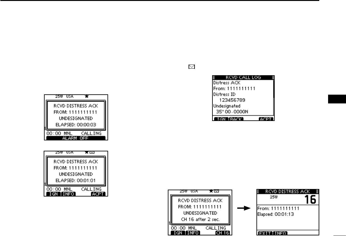
54
7
DSC OPERATION
1
2
3
4
5
6
7
8
9
10
11
12
13
14
15
16
Receiving a Distress Acknowledgement D
When a Distress Acknowledgement sent to another ship is
received:
The emergency alarm sounds for 2 minutes. ±
“ RCVD DISTRESS ACK” pops up and the LCD backlight ±
blinks.
Push [ALARM OFF] to stop the alarm and the blinking q
backlight.
Push a soft key to select your desired action. w
[IGN]
±Push to return to the normal operating mode.
s4HETRANSCEIVEREXITSTHE$3#MODE
s"YPUSHING;044=THETRANSCEIVERALSOEXITSTHE$3#MODE
sh ” continues to blink and the Call is stored in the Received
Call Log.
[INFO]
±Push to display the Received call information. (p. 65)
[ACPT]
Push to accept the call. ±
And then, push [CH 16] to switch the operating channel
to Channel 16, and then monitor it, as a coast station
may require assistance.
s)FYOUHAVENTPUSHED;#(=WITHINSECONDSTHEOPERAT-
ing channel automatically switches to Channel 16. (p. 69)
Push
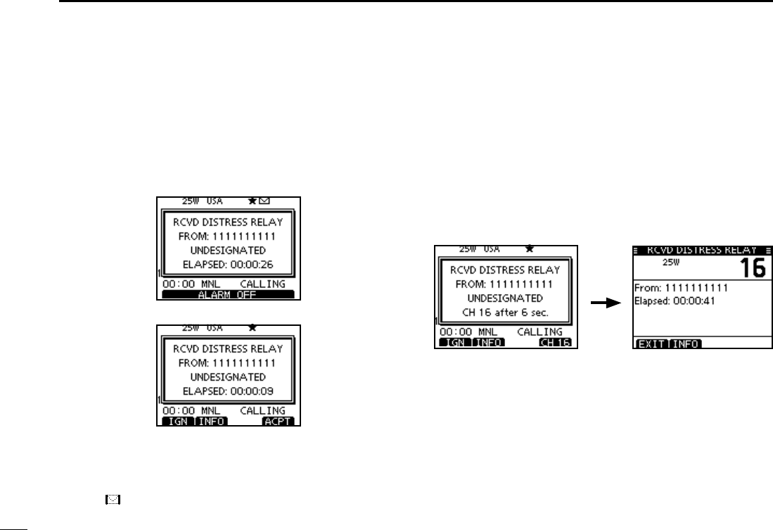
55
7DSC OPERATION
Receiving D a Distress Relay Call
When a Distress Relay call is received:
The emergency alarm sounds for 2 minutes. ±
“ RCVD DISTRESS RELAY” pops up and the LCD back- ±
light blinks.
Push [ALARM OFF] to stop the alarm and the blinking q
backlight.
Push a soft key to select your desired action. w
[IGN]
±Push to return to the normal operating mode.
s4HETRANSCEIVEREXITSTHE$3#MODE
s"YPUSHING;044=THETRANSCEIVERALSOEXITSTHE$3#MODE
sh ” continues to blink and the Call is stored in the Received
Call Log.
[INFO]
±Push to display the Received call information. (p. 65)
[ACPT]
Push to accept the call. ±
And then, push [CH 16] to switch the operating channel
to Channel 16, and then monitor it, as a coast station
may require assistance.
s)FYOUHAVENTPUSHED;#(=WITHINSECONDSTHEOPERAT-
ing channel automatically switches to Channel 16. (p. 69)
Push
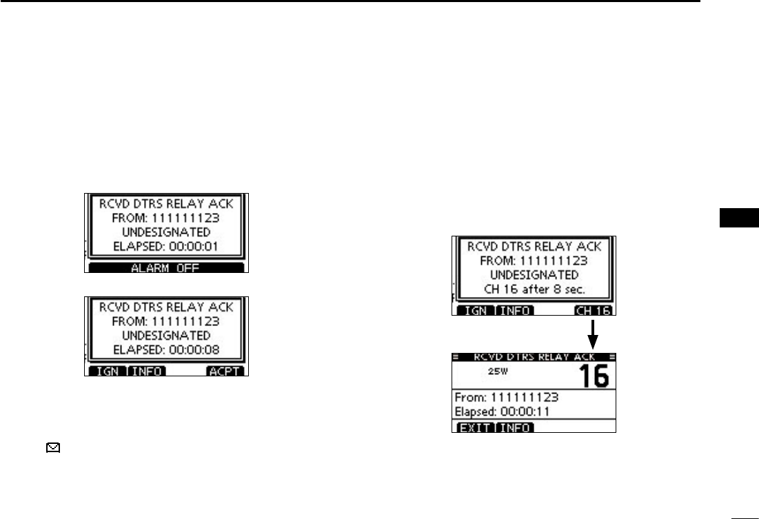
56
7
DSC OPERATION
1
2
3
4
5
6
7
8
9
10
11
12
13
14
15
16
D Receiving a Distress Relay Acknowledgement
When a Distress Relay Acknowledgement is received:
± The emergency alarm sounds for 2 minutes.
± “ RCVD DIST RELAY ACK” pops up and the LCD backlight
blinks.
q Push [ALARM OFF] to stop the alarm and the blinking
backlight.
w Push a soft key to select your desired action.
[IGN]
±Push to return to the normal operating mode.
s4HETRANSCEIVEREXITSTHE$3#MODE
s"YPUSHING;044=THETRANSCEIVERALSOEXITSTHE$3#MODE
sh ” continues to blink and the Call is stored in the Received
Call Log.
[INFO]
±Push to display the Received call information. (p. 65)
[ACPT]
Push to accept the call. ±
And then, push [CH 16] to switch the operating channel
to Channel 16, and then monitor it, as a coast station
may require assistance.
s)FYOUHAVENTPUSHED;#(=WITHINSECONDSTHEOPERAT-
ing channel automatically switches to Channel 16. (p. 69)
Push
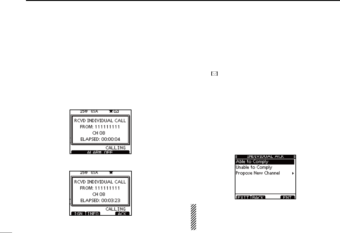
57
7DSC OPERATION
Receiving an Individual Call D
When an Individual Call is received:
± The alarm sounds for 2 minutes.
± “RCVD INDIVIDUAL CALL” pops up. The LCD backlight
may blink for 2 minutes, depending on the received Cat-
egory.
Push [ALARM OFF] to stop the alarm and the blinking q
backlight.
s)F;!,!2-/&&=ISNOTPUSHEDWITHINMINUTESTHENEXTSCREEN
may appear, depending on the received Category.
Push a soft key to select your desired action. w
[IGN]
±
Push to ignore the Call and return to the normal operating
mode.
s4HETRANSCEIVEREXITSTHE$3#MODE
s4HE#ALLISSTOREDINTHE2ECEIVED#ALL,OG
sh ” continues to blink and the Call is stored in the Received
Call Log.
[INFO]
±Push to display the Received call information. (p. 65)
[ACK]
± Push to display the “INDIVIDUAL ACK” screen to re-
ply to the Call, and select the channel specified by the
calling station for voice communication, depending on
your situation. See page 30 for details of the Individual
Acknowledgement procedure.
When “INDIVIDUAL ACK” is set to “Auto (Unable),” the
transceiver automatically replies to the Call. In that case,
both the TX and RX calls are stored in the Transmitted and
Received Call Logs.
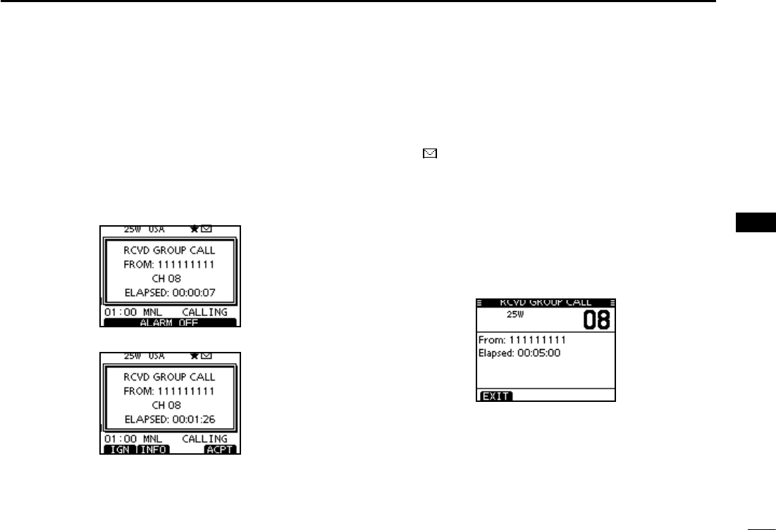
58
7
DSC OPERATION
1
2
3
4
5
6
7
8
9
10
11
12
13
14
15
16
Receiving a Group Call D
When a Group Call is received:
± The alarm sounds for 2 minutes.
± “RCVD GROUP CALL” pops up. The LCD backlight may
blink for 2 minutes, depending on the received Category.
Push [ALARM OFF] to stop the alarm and the blinking q
backlight.
s)F;!,!2-/&&=ISNOTPUSHEDWITHINMINUTESTHENEXTSCREEN
may appear, depending on the received Category.
Push a soft key to select your desired action. w
[IGN]
±Push to ignore the Call and return to the normal operat-
ing mode.
s4HETRANSCEIVEREXITSTHE$3#MODE
sh ” continues to blink and the Call is stored in the Received
Call Log.
[INFO]
±Push to display the Received call information. (p. 65)
[ACPT]
± Push to monitor the channel specified by the calling sta-
tion (Example: 08) for an announcement from the call-
ing station.
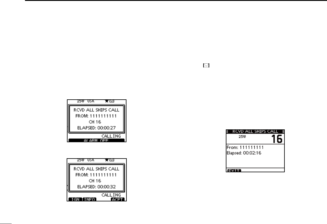
59
7DSC OPERATION
Receiving an All Ships Call D
When an All Ships Call is received:
± The alarm sounds for 2 minutes.
± “RCVD ALL SHIPS CALL” pops up. The LCD backlight may
blink for 2 minutes, depending on the received Category.
Push [ALARM OFF] to stop the alarm and the blinking q
backlight.
s)F;!,!2-/&&=ISNOTPUSHEDWITHINMINUTESTHENEXTSCREEN
may appear, depending on the received Category.
Push a soft key to select your desired action. w
[IGN]
±Push to ignore the Call and return to the normal operat-
ing mode.
s4HETRANSCEIVEREXITSTHE$3#MODE
sh ” continues to blink and the Call is stored in the Received
Call Log.
[INFO]
±Push to display the Received call information. (p. 65)
[ACPT]
± Push to monitor the channel specified by the calling sta-
tion (Example: 16) for an announcement from the call-
ing station.
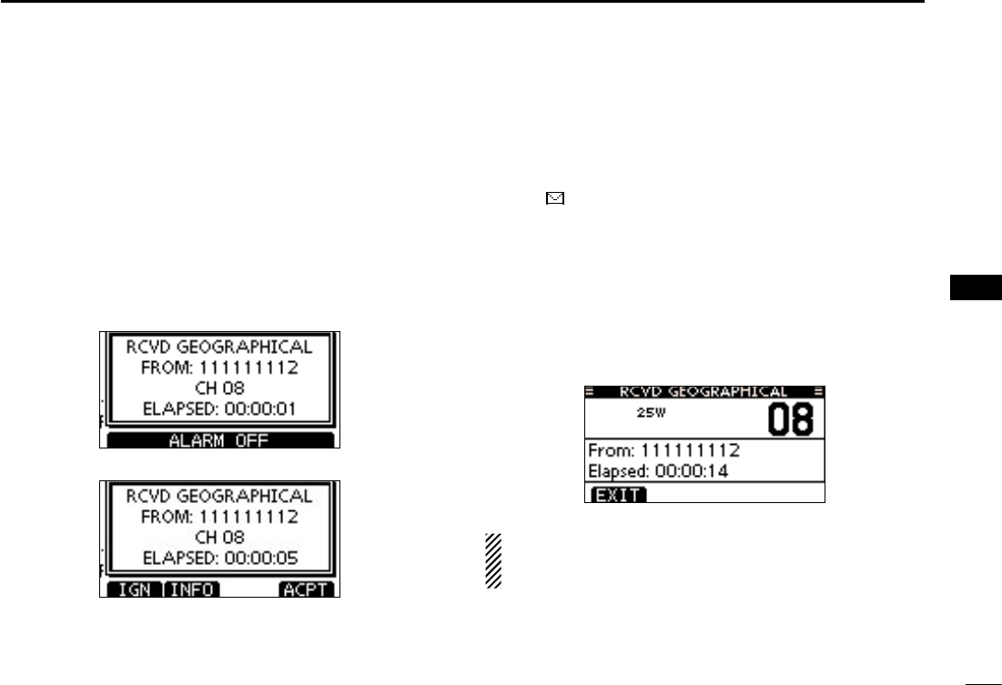
60
7
DSC OPERATION
1
2
3
4
5
6
7
8
9
10
11
12
13
14
15
16
Receiving a Geographical Area Call D
When a Geographical Area Call (for the area you are in) is
received:
± The alarm sounds for 2 minutes.
± “RCVD GEOGRAPHICAL CALL” pops up. The LCD back-
light may blink for 2 minutes, depending on the received
Category.
Push [ALARM OFF] to stop the alarm and the blinking q
backlight.
s)F;!,!2-/&&=ISNOTPUSHEDWITHINMINUTESTHENEXTSCREEN
may appear, depending on the received Category.
Push a soft key to select your desired action. w
[IGN]
±Push to ignore the Call and return to the normal operat-
ing mode.
s4HETRANSCEIVEREXITSTHE$3#MODE
sh ” continues to blink and the Call is stored in the Received
Call Log.
[INFO]
±Push to display the Received call information. (p. 65)
[ACPT]
± Push to monitor the channel specified by the calling sta-
tion (Example: 08) for an announcement from the call-
ing station.
When no GPS receiver is connected or if there is a prob-
lem with the connected receiver, all Geographical Area
Calls are received, regardless of your position.
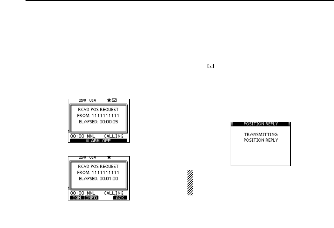
61
7DSC OPERATION
Receiving a Position Request Call D
When a Position Request Call is received:
± The alarm sounds for 2 minutes.
± “RCVD POS REQUEST” pops up. The LCD backlight
blinks for 2 minutes.
Push [ALARM OFF] to stop the alarm and the blinking q
backlight.
s)F;!,!2-/&&=ISNOTPUSHEDWITHINMINUTESTHENEXTSCREEN
may appear, depending on the received Category.
w Push a soft key to select your desired action.
[IGN]
±Push to ignore the Call and return to the normal operat-
ing mode.
s4HETRANSCEIVEREXITSTHE$3#MODE
sh ” continues to blink and the Call is stored in the Received
Call Log.
[INFO]
±Push to display the Received call information. (p. 65)
[ACK]
± Push to display the “POSITION REPLY” screen and
send a reply to the Call. (p. 47)
When “POSITION ACK” is set to “Auto TX,” the transceiver
automatically replies to the Call. In that case, both the TX
and RX calls are stored in the Transmitted and Received
Call Logs.
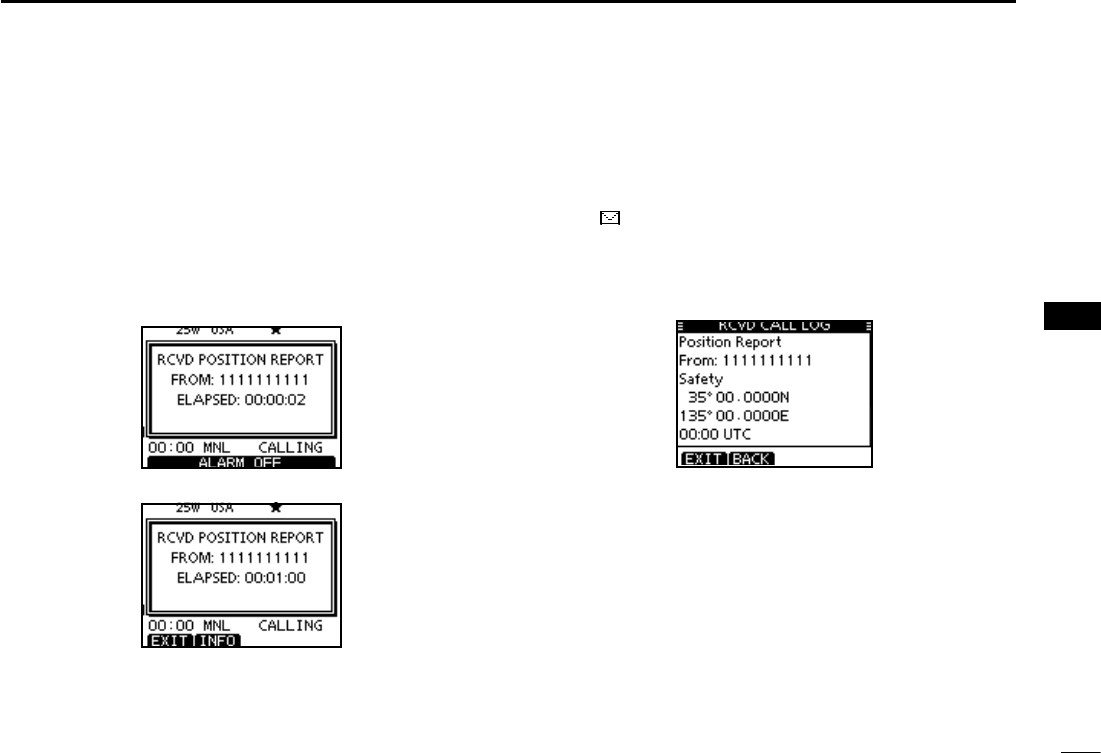
62
7
DSC OPERATION
1
2
3
4
5
6
7
8
9
10
11
12
13
14
15
16
Receiving a Position Report Call D
When a Position Report Call is received:
± The alarm sounds for 2 minutes.
± “RCVD POSITION REPORT” pops up. The LCD backlight
blinks for 2 minutes.
Push [ALARM OFF] to stop the alarm and the blinking q
backlight.
s)F;!,!2-/&&=ISNOTPUSHEDWITHINMINUTESTHENEXTSCREEN
may appear, depending on the received Category.
Push a soft key to select your desired action. w
[EXIT]
±Push to ignore the Call and return to the normal operat-
ing mode.
s4HETRANSCEIVEREXITSTHE$3#MODE
sh ” continues to blink and the Call is stored in the Received
Call Log.
[INFO]
±Push to display the Received call information. (p. 65)
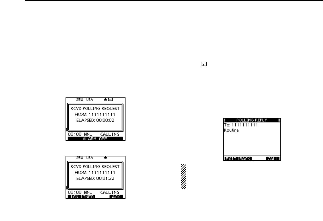
63
7DSC OPERATION
D Receiving a Polling Request call
When a Polling Request call is received:
± The alarm sounds for 2 minutes.
± “RCVD POLLING REQUEST” pops up. The LCD backlight
blinks for 2 minutes.
Push [ALARM OFF] to stop the alarm and the blinking q
backlight.
s)F;!,!2-/&&=ISNOTPUSHEDWITHINMINUTESTHENEXTSCREEN
may appear, depending on the received Category.
Push a soft key to select your desired action. w
[IGN]
±Push to ignore the Call and return to the normal operat-
ing mode.
s4HETRANSCEIVEREXITSTHE$3#MODE
sh ” continues to blink and the Call is stored in the Received
Call Log.
[INFO]
±Push to display the Received call information. (p. 65)
[ACK]
± Push to display the “POLLING REPLY” screen to reply
to the Call. (p. 51)
When “POSITION ACK” is set to “Auto”, the transceiver
automatically replies to the Call. In that case, both the TX
and RX calls are stored in the Transmitted and Received
Call Logs.
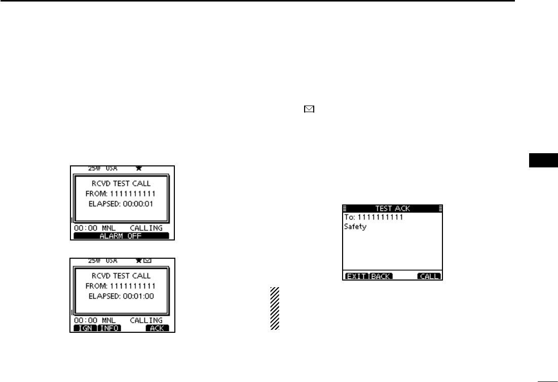
64
7
DSC OPERATION
1
2
3
4
5
6
7
8
9
10
11
12
13
14
15
16
D Receiving a Test Call
When a Test Call is received:
± The alarm sounds for 2 minutes.
± “RCVD TEST CALL” pops up. The LCD backlight blinks for
2 minutes.
Push [ALARM OFF] to stop the alarm and the blinking q
backlight.
s)F;!,!2-/&&=ISNOTPUSHEDWITHINMINUTESTHENEXTSCREEN
may appear, depending on the received Category.
w Push a soft key to select your desired action.
[IGN]
±Push to ignore the Call and return to the normal operat-
ing mode.
s4HETRANSCEIVEREXITSTHE$3#MODE
sh ” continues to blink and the Call is stored in the Received
Call Log.
[INFO]
±Push to display the Received call information. (p. 65)
[ACK]
± Push to display the “TEST ACK” screen to reply to the
Call. (p. 45)
When “TEST ACK” is set to “Auto TX,” the transceiver au-
tomatically replies to the Call. In that case, both the TX and
RX calls are stored in the Transmitted and Received Call
Logs.
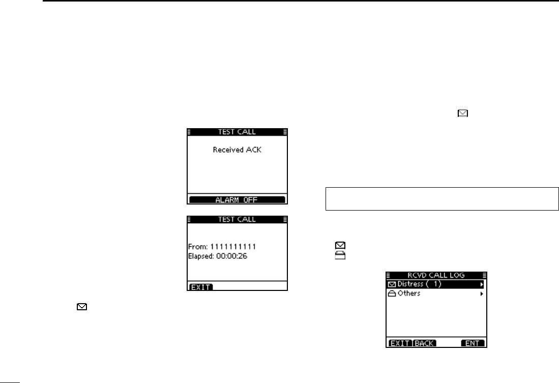
65
7DSC OPERATION
D Receiving a Test Acknowledgement Call
When a Test Acknowledgement Call is received:
The alarm sounds for 2 minutes. ±
“Received ACK” pops up. The LCD backlight blinks for 2 ±
minutes.
Received Call log N
The transceiver automatically stores up to 50 distress mes-
sages and 50 other messages, and they can be used as a
supplement to your logbook.
s7HILEINTHENORMALOPERATINGMODEh ” blinks in the upper right
corner of the LCD when there is an unread DSC message.
Distress message D
Push the soft key [LOG] to enter “RCVD CALL LOG” in the q
DSC CALLS menu, or you can enter it through the Menu
screen.
eMENUf ¶ eDSCf ¶
eReceived Call Logf
(Push [MENU]) (Select icon)
(Rotate Dial, then push [ENT].)
Push [ wY] or [Z] to select “Distress,” then push [ENT].
s4HE$ISTRESSMESSAGESARESTOREDINh$ISTRESSv
sh ” appears when there are unread DSC messages.
sh ” appears when there are no unread DSC messages.
s.OICONAPPEARSWHENTHEREARENO$3#MESSAGES
q Push [ALARM OFF] to stop
the alarm and the blinking
backlight.
s)F;!,!2-/&&=ISNOTPUSHED
within 2 minutes, the next
screen may appear, depending
on the received Category.
w Push a soft key to select your
desired action.
[EXIT]
± Push to return to the nor-
mal operating mode.
s4HE TRANSCEIVER EXITS THE
DSC mode.
sh ” continues to blink and
the Call is stored in the Re-
ceived Call Log.
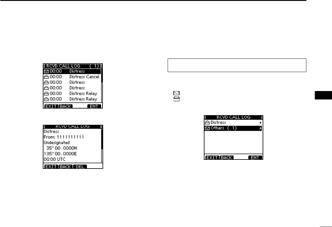
66
7
DSC OPERATION
1
2
3
4
5
6
7
8
9
10
11
12
13
14
15
16
e Push [Y] or [Z] to select the desired item, then push
[ENT].
s4HEMESSAGEINTHEUNOPENEDlLEHASNOTBEENREAD
Rotate Dial or Push [ rY] or [Z] to scroll the DSC message
contents.
To delete the displayed DSC message, push [DEL]. t
s4HECONlRMATIONSCREENAPPEARSTHENPUSH;/+=TODELETE
Push [EXIT] to return to the normal operating mode. y
D Other messages
Push [LOG] to enter “RCVD CALL LOG” in the DSC CALLS q
menu, or you can enter it through the Menu screen.
eMENUf ¶ eDSCf ¶
eReceived Call Logf
(Push [MENU]) (Select icon)
(Rotate Dial, then push [ENT].)
Push [ wY] or [Z] to select “Others,” then push [ENT].
s4HEMESSAGESOTHERTHANTHE$ISTRESSARESTOREDINh/THERSv
sh ” appears when there are unread DSC messages.
sh ” appears when there are no unread DSC messages.
s.OICONAPPEARSWHENTHEREARENO$3#MESSAGES
Continued on the next page
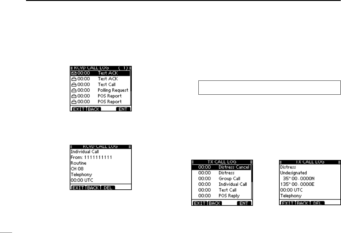
67
7DSC OPERATION
D Other messages (Continued)
e Push [Y] or [Z] to select the desired item, then push
[ENT].
s4HEMESSAGEINTHEUNOPENEDlLEHASNOTBEENREAD
r Rotate Dial to scroll the DSC message contents.
s4HESTOREDMESSAGEHASVARIOUSINFORMATIONDEPENDINGONTHE
DSC call type.
To delete the displayed DSC message, push [DEL]. t
s4HECONlRMATIONSCREENAPPEARSTHENPUSH;/+=TODELETE
Push [EXIT] to return to the normal operating mode. y
Transmitted Call log N
The transceiver automatically stores up to 50 transmitted
calls, and the logs can be used as a supplement to your log-
book.
Enter “TX CALL LOG” in the DSC CALLS menu. q
eMENUf ¶ eDSCf ¶
eTransmitted Call Logf
(Push [MENU]) (Select icon)
(Rotate Dial, then push [ENT].)
Push [ wY] or [Z] to select the desired item, then push
[ENT].
Rotate Dial to scroll the DSC message contents. e
To delete the displayed DSC message, push [DEL]. r
s4HECONlRMATIONSCREENAPPEARSTHENPUSH;/+=TODELETE
Push [EXIT] to return to the normal operating mode. t
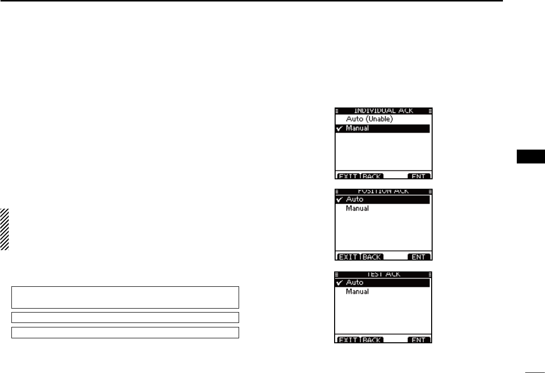
68
7
DSC OPERATION
1
2
3
4
5
6
7
8
9
10
11
12
13
14
15
16
DSC Settings N
D Position Input (See page 22)
D Add Individual ID/Group ID (See pages 19, 20)
D Delete Individual ID/Group ID (See page 21)
D Automatic Acknowledgement
These items set the Automatic Acknowledgement function to
“Auto TX” or “Manual TX.”
When an Individual, Position Request, Polling Request or
Test Call is received, the transceiver automatically transmits
an Individual Acknowledgement, Position Reply, Polling Re-
ply or Test Acknowledgement Call, respectively.
When “INDIVIDUAL ACK” is set to “Auto TX,” the trans-
ceiver automatically transmits the Acknowledgment call
including “Unable to Comply” (No Reason Given) after re-
ceivng the Individual call.
q
Enter either “INDIVIDUAL ACK,” “POSITION ACK” or “TEST
ACK” in the DSC Settings menu.
eMENUf ¶ eDSC SETf ¶ e
Individual ACK
f
(Push [MENU]) (Select icon)
(Rotate Dial, then push [ENT].)
eMENUf ¶ eDSC SETf ¶ e
Position ACK
f
eMENUf ¶ eDSC SETf ¶ e
Test ACK
f
Rotate Dial w
to select “Auto TX” or “Manual TX,” then push
[ENT].
s0USH;"!#+=TOCANCELANDRETURNTOTHE$3#3ETTINGSMENU
(default)
(default)
(default)
Push [EXIT] to return to the normal operating mode. e
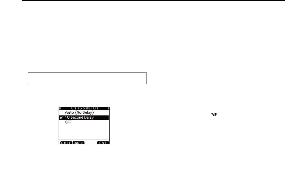
69
7DSC OPERATION
D Channel 16 Switch function
By regulation, after receiving a Distress call, the transceiv-
er switches the operating channel to Channel 16. However,
when this setting is set to “OFF,” the function enables the
transceiver to remain on the operating channel, even after
receiving a Distress call.
q Enter “CH 16 SWITCH”
in the DSC Settings menu
.
eMENUf ¶ eDSC SETf ¶ eCH 16 Switchf
(Push [MENU]) (Select icon)
(Rotate Dial, then push [ENT].)
w Rotate Dial to set the Channel 16 Switch function to “Auto
(No Delay),” “10 Second Delay” or “OFF
,” then push [ENT].
s0USH;"!#+=TOCANCELANDRETURNTOTHE$3#3ETTINGSMENU
(default)
Auto (No Delay) : After receiving a Distress call, and
[ACPT] is pushed on the confirmation
screen, the transceiver immediately
switches to Channel 16.
10 Second Delay : After receiving a Distress call, and
[ACPT] is pushed on the confirma-
tion screen, the transceiver remains
on the current operating channel for
10 seconds. After that, the transceiver
automatically switches to Channel 16.
(default)
OFF : Even after receiving a Distress call,
the transceiver remains on the operat-
ing channel.
sh ” appears.
Push [EXIT] to return to the normal operating mode. e
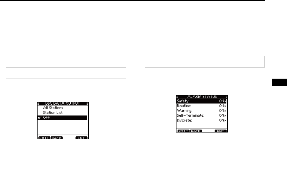
70
7
DSC OPERATION
1
2
3
4
5
6
7
8
9
10
11
12
13
14
15
16
D DSC Data Output
Select an option for the DSC Data Output function.
When receiving a DSC call, this function makes the trans-
ceiver send the DSC data from its NMEA Output port to a
connected device.
q Enter “DSC DATA OUTPUT”
in the DSC Settings menu
.
eMENUf ¶ eDSC SETf ¶ eDSC Data Outputf
(Push [MENU]) (Select icon)
(Rotate Dial, then push [ENT].)
w Rotate Dial to set the DSC Data Output function to “All Sta-
tion,” “List Station” or “OFF
,” then push [ENT].
s0USH;"!#+=TOCANCELANDRETURNTOTHE$3#3ETTINGSMENU
(default)
All Station : Outputs the call from any vessel from the
NMEA Output port.
List Station : Outputs the call from any vessels listed on the
Individual ID screen.
OFF : Does not
output any call to the external equip-
ment.
Push [EXIT] to return to the normal operating mode. e
D Alarm
Set the Alarm function ON or OFF, depending on the Cat-
egory or Status.
q Enter “ALARM”
in the DSC Settings menu
.
eMENUf ¶ eDSC SETf ¶ eAlarmf
(Push [MENU]) (Select icon)
(Rotate Dial, then push [ENT].)
w Rotate Dial to select
the status, then push [ENT].
s0USH;"!#+=TOCANCELANDRETURNTOTHE$3#3ETTINGSMENU
sh3AFETYvh2OUTINEvh7ARNINGvh3ELF4ERMINATEvANDh$ISCRETEvARE
selectable. (default: ON)
Rotate Dial to set the Alarm setting to “ON” or “OFF.” e
Push [EXIT] to return to the normal operating mode. r
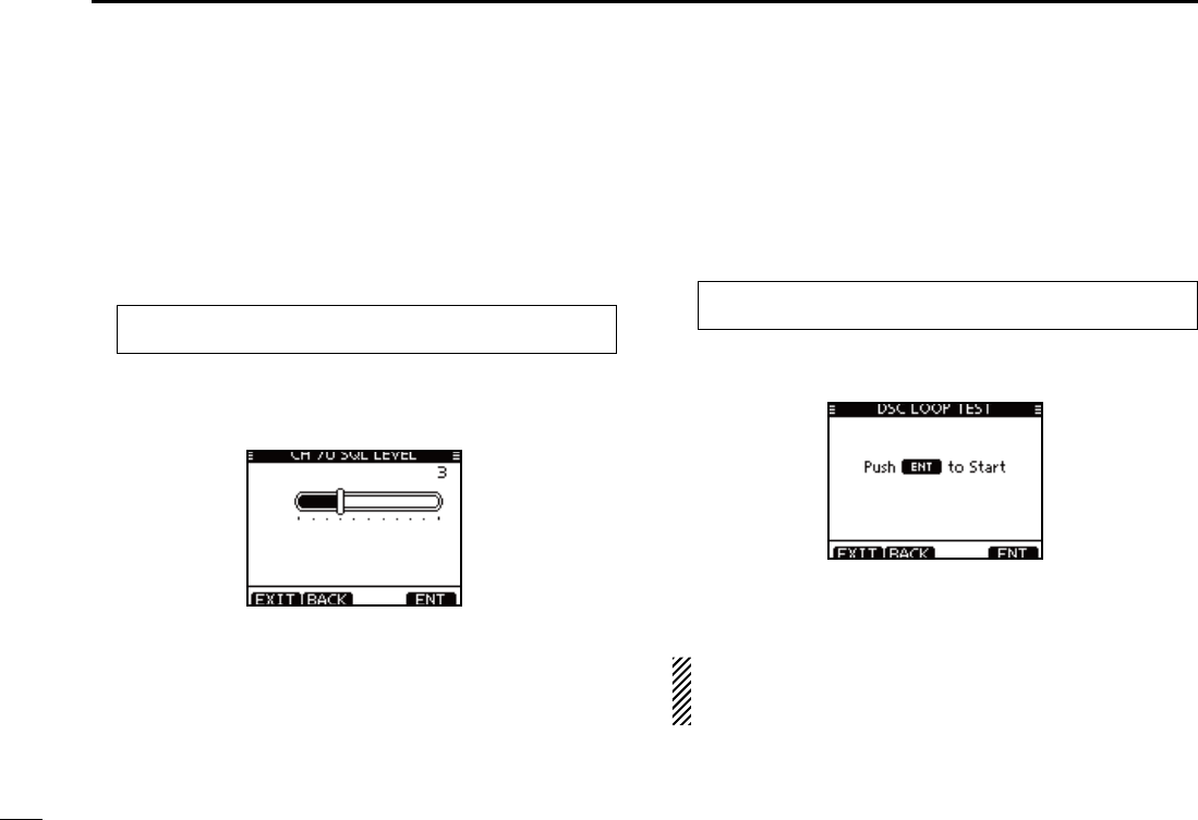
71
7DSC OPERATION
D Channel 70 Squelch level
Set the squelch level on Channel 70.
The transceiver has 11 squelch levels between 1 (loose
squelch) and 10 (tight squelch) and OPEN.
OPEN is completely open.
q Enter “CH 70 SQL Level”
in the DSC Settings menu
.
eMENUf ¶ eDSC SETf ¶ eCH 70 SQL Levelf
(Push [MENU]) (Select icon)
(Rotate Dial, then push [ENT].)
w Rotate Dial to adjust the squelch level until the noise just
disappears, then push [ENT].
s0USH;"!#+=TOCANCELANDRETURNTOTHE$3#3ETTINGSMENU
(default)
Push [EXIT] to return to the normal operating mode. e
D DSC Loop Test
The DSC loop test function sends transmit DSC signals to
the receive AF circuit to compare and check the TX and RX
signals at the AF level.
q Enter “DSC LOOP TEST”
in the DSC Settings menu
.
eMENUf ¶ eDSC SETf ¶ eDSC Loop Testf
(Push [MENU]) (Select icon)
(Rotate Dial, then push [ENT].)
w Push [ENT] to start the DSC loop test.
s0USH;"!#+=TOCANCELANDRETURNTOTHE$3#3ETTINGSMENU
s7HENTHETRANSMIT$3#ANDRECEIVE$3#SIGNALSAREMATCHED
“OK” appears.
Push [EXIT] to return to the normal operating mode. e
If “NG” appears in step w, either or both TX and RX DSC
circuits has a problem. In that case, you will have to send
the transceiver to your nearest dealer for repair.
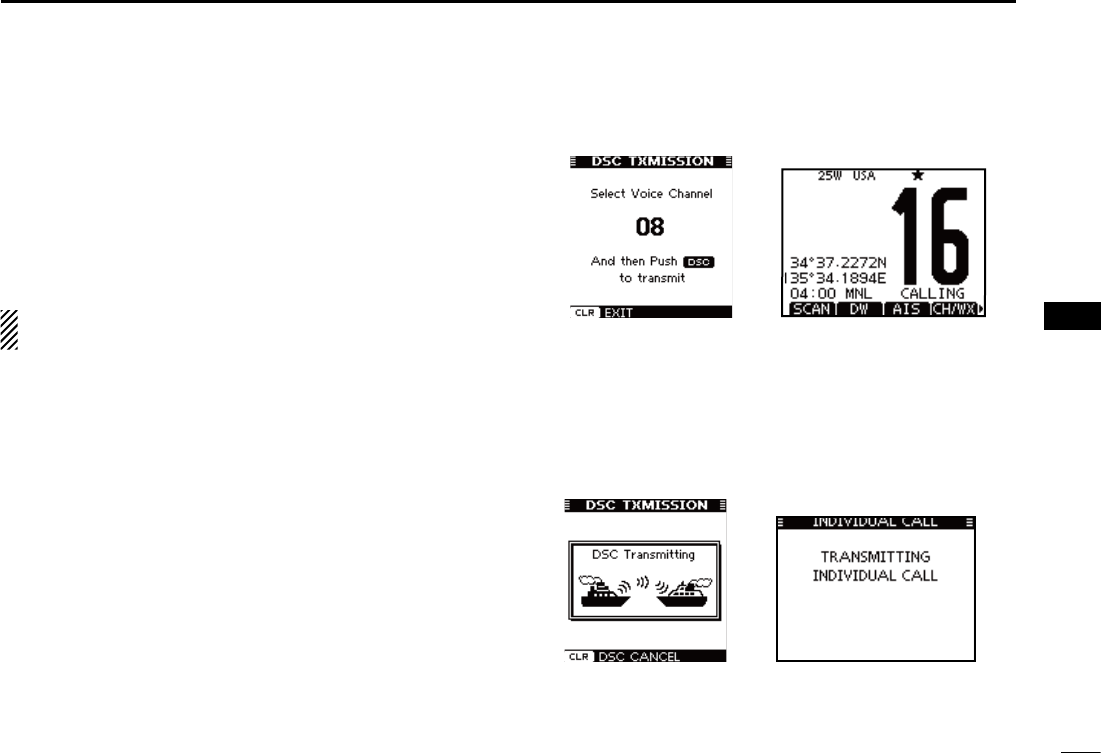
72
7
DSC OPERATION
1
2
3
4
5
6
7
8
9
10
11
12
13
14
15
16
When the optional MA-500TR CLASS B AIS TRANSPONDER is
connected to your transceiver, an individual DSC call can be
transmitted to a selected AIS target, without needing to enter
the target’s MMSI code. In this case, the call type is automati-
cally set to Routine.
See page 102 for connecting instructions.
To ensure correct operation of the DSC function, make
sure you correctly set the CH70 SQL Level. (p. 71)
Step 1: Transponder’s operation
Select a desired AIS target on the plotter, target list or dan- q
ger list display.
s9OUCANALSOGOTOTHENEXTSTEPWHENEVERTHEDETAILSCREENOF
the AIS target is displayed.
s-AKESURETHETRANSCEIVERISINTHENORMALOPERATINGMODE/TH-
erwise, you cannot make an individual DSC call using the tran-
sponder.
Push [DSC] to display the voice channel selection screen, w
and then push [Y] or [Z] to select a desired voice chan-
nel*.
s6OICECHANNELSAREALREADYPRESETINTOTHETRANSPONDERINRECOM-
mended order.
* When a coast station is selected in step q, a voice channel will
be specified by the coast station, therefore you cannot change
the channel. The transponder will display “Voice Channel is
specified by the Base station,” in this case.
Push [DSC] to transmit an individual DSC call to the AIS e
target.
s)F#HANNELISBUSYTHETRANSCEIVERSTANDSBYUNTILTHECHANNEL
becomes clear.
s)FTHETRANSCEIVERCANNOTMAKETHECALLTHETRANSPONDERWILLDIS-
play “DSC Transmission FAILED.”
Making an Individual call using an AIS transponder N
Transponder’s display Transceiver’s display
Transponder’s display Transceiver’s display
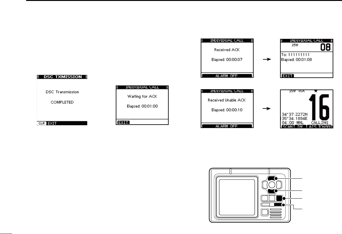
73
7DSC OPERATION
After making the individual DSC call, the transponder will r
display “DSC Transmission COMPLETED.”
s0USH;#,%!2=TORETURNTOTHESCREENDISPLAYEDBEFOREYOUEN-
tered the voice channel selection screen in step w.
s4HETRANSCEIVERSTANDSBYON#HANNELUNTILANACKNOWLEDGE-
ment is received.
Transponder’s display Transceiver’s display
Step 2: Transceiver’s operation
When the acknowledgement is received, beeps sound. t
If the acknowledgement ‘Able to comply’ is received, ±
push [ALARM OFF] to stop the beeps, and then select
the intership channel specified in step w.
s!DIFFERENTINTERSHIPCHANNELWILLBESELECTEDIFTHESTATIONYOU
called cannot use the channel.
s4OREPLYPUSH;044=ANDSPEAKATANORMALVOICELEVEL
s9OUCANCHECKTHE--3)CODEORTHENAMEIFPROGRAMMED
of the AIS target on the display.
If the acknowledgement ‘Unable to comply’ is received, ±
push [ALARM OFF] to stop the beeps, and then return
to the operating channel before you entered the MENU
screen.
y
After the communication is finished, push [EXIT] to return
to the normal operating mode.
[DSC]
[CLEAR]
[Z]
[Y]
TRANSPONDER
‘Able to comply’ is received
‘Unable to comply’ is received
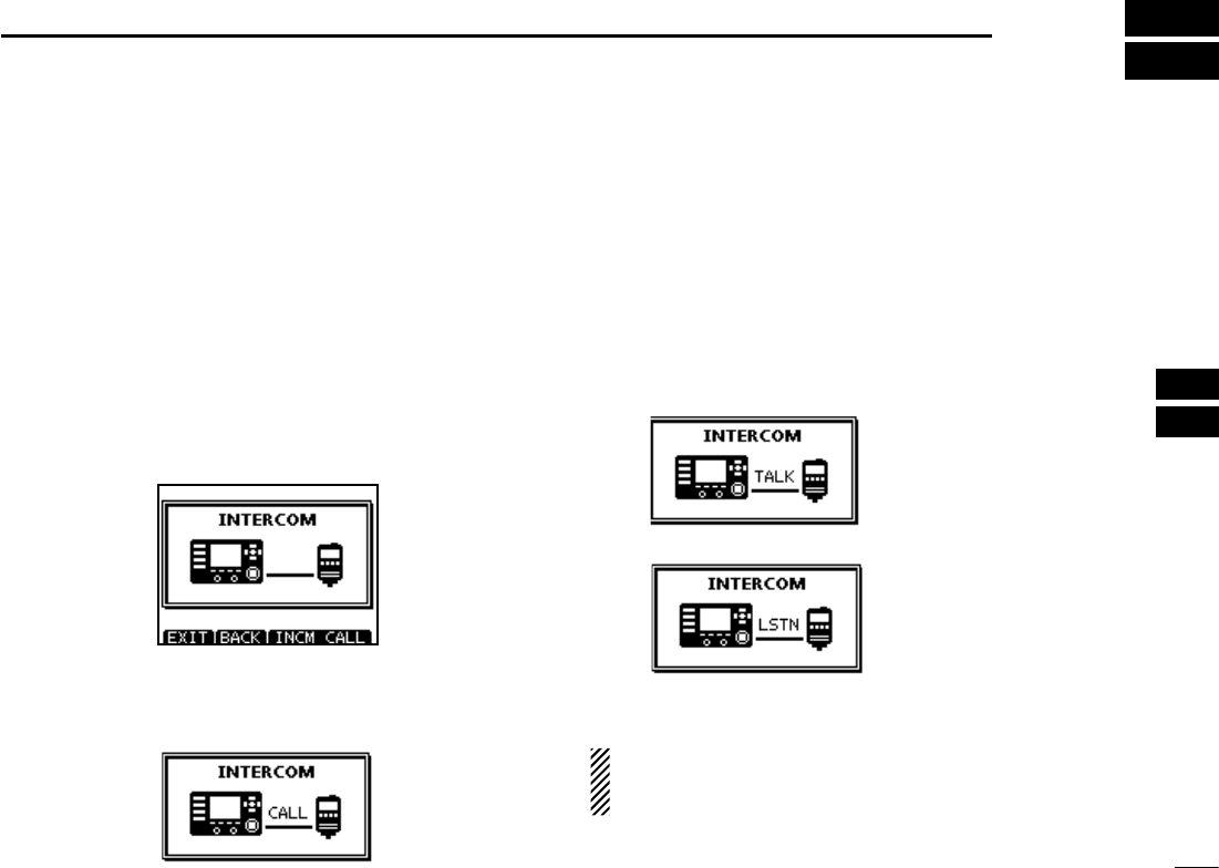
74
8
OTHER FUNCTIONS
1
2
3
4
5
6
7
8
9
10
11
12
13
14
15
16
Intercom operation N
The optional Intercom function allows you to talk between the
deck and the cabin. The optional HM-195 COMMANDMICIV™ is
required for Intercom operation.
Connect the HM-195 COMMANDMICIV™ as described on page
106.
s4RANSMITTINGISDISABLEDWHILEUSINGTHEINTERCOM
s4HERECEIVEDSIGNALISMUTEDWHILEUSINGTHEINTERCOM
Hold down [PWR](Dial) to turn ON the power. q
s4HE COMMAND MICROPHONE POWER IS AUTOMATICALLY TURNED /.
even if the power is OFF.
Push [INCM] to enter the Intercom mode. w
Hold down [INCM CALL] to sound the intercom beeps. e
s4HE TRANSCEIVER AND THE COMMAND MICROPHONE SOUND BEEPS
while holding down [INCM CALL].
sh#!,,vAPPEARS
After releasing [INCM CALL], hold down [PTT] and speak r
into the microphone at a normal voice level.
sh4!,+vAPPEARSONTHECALLERSDISPLAYORh,34.vAPPEARSONTHE
listener’s display.
s
To adjust the transceiver’s intercom volume level, rotate Dial.
s4OADJUSTTHE(-SINTERCOMVOLUMELEVELROTATE;6/,31,=
(Dial) on the HM-195.
After releasing [PTT], you can hear the response through t
the speaker.
y
To return to the normal operating mode, push [EXIT].
While in the Intercom mode, the transmit and receive func-
tions are disabled. When the transceiver is transmitting,
the Intercom function is disabled.
On the caller’s display
On the listener’s display
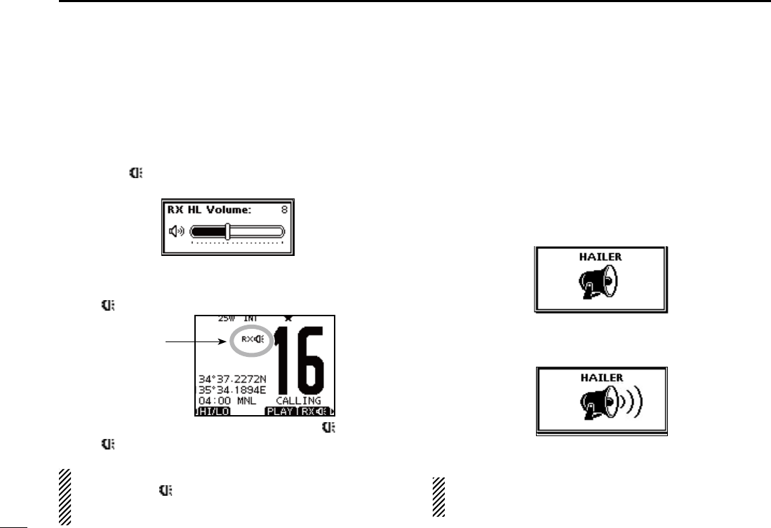
75
8OTHER FUNCTIONS
RX Speaker function N
The RX Speaker function enables you to hear the received
audio on the deck or bridge through a Hailer.
Connect a PA speaker as described on page 83.
Push q
[RX ]
to enter the RX Speaker mode.
s4HE283PEAKERVOLUMELEVELADJUSTMENTSCREENISDISPLAYED
Rotate Dial or push [ wY]/[Z]/[Ω]/[≈] to adjust the RX Speak-
er volume level, and then push [ENT].
sh28
” appears.
e
To return to normal operating mode,
push
[RX ].
sh28 ” disappears.
To adjust the audio output level in the RX Speaker mode,
hold down
[RX ] for 1 second to display
the RX Speaker
volume level adjustment screen, and then rotate Dial. After
adjusting, push [ENT] to set it.
Hailer operation N
The IC-M506 has a hailer function for voice amplification over
a loudspeaker, making it unnecessary to leave the bridge to
talk a hailing party.
Connect an external hailer speaker (25 W nominal at 13.8 V/4
˘) as described on page 83.
s4RANSMITTINGISNOTPOSSIBLEDURINGHAILEROPERATION
Push [HAILER] to enter the Hailer mode. q
w Hold down [PTT] and speak at a normal voice level.
s7HILEHOLDINGDOWN;044=THESCREENBELOWISDISPLAYED
s4OADJUSTTHEHAILERLEVELROTATE$IAL
e Push [EXIT] to return to normal operating screen.
While in the hailer mode, the transmit and receive func-
tions are disabled. When the transceiver is transmitting,
the hailer function is disabled.
Appears
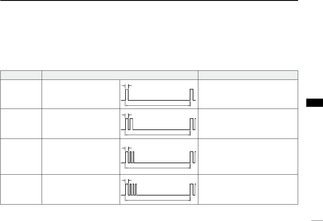
76
8
OTHER FUNCTIONS
1
2
3
4
5
6
7
8
9
10
11
12
13
14
15
16
Horn function N
D Automatic foghorn function
The automatic foghorn function sounds a horn repeatedly
until the function is turned OFF. Four patterns are available
for varying conditions.
TYPE PATTERN USAGE
UNDERWAY
STOP
SAIL
TOW
One 5-second blasts every 120
seconds.
Two 5-second blasts (separated
by 2 seconds) every 120 sec-
onds.
One 5-second blast followed
by two 1-second blasts (each
separated by 2 seconds) every
120 seconds.
One 5-second blast followed
by three 1-second blasts (each
separated by 2-seconds) every
120 seconds.
Motor vessel underway and making way.
Motor vessel underway but stopped (not
making way).
Sailing vessel underway, fishing vessel
(underway or anchored), vessel not under
command, a vessel restricted in her ability
to maneuver (underway or at anchor), or a
vessel towing or pushing another ahead.
Vessel under tow (manned).
5s1
120s
5s1
2s
1s
120s
5s1
2s
1s
120s
5s1
2s 120s
The foghorn outputs from the hailer speaker. To use this
function, the hailer speaker must be connected to the trans-
ceiver. See page 83 for connection details.
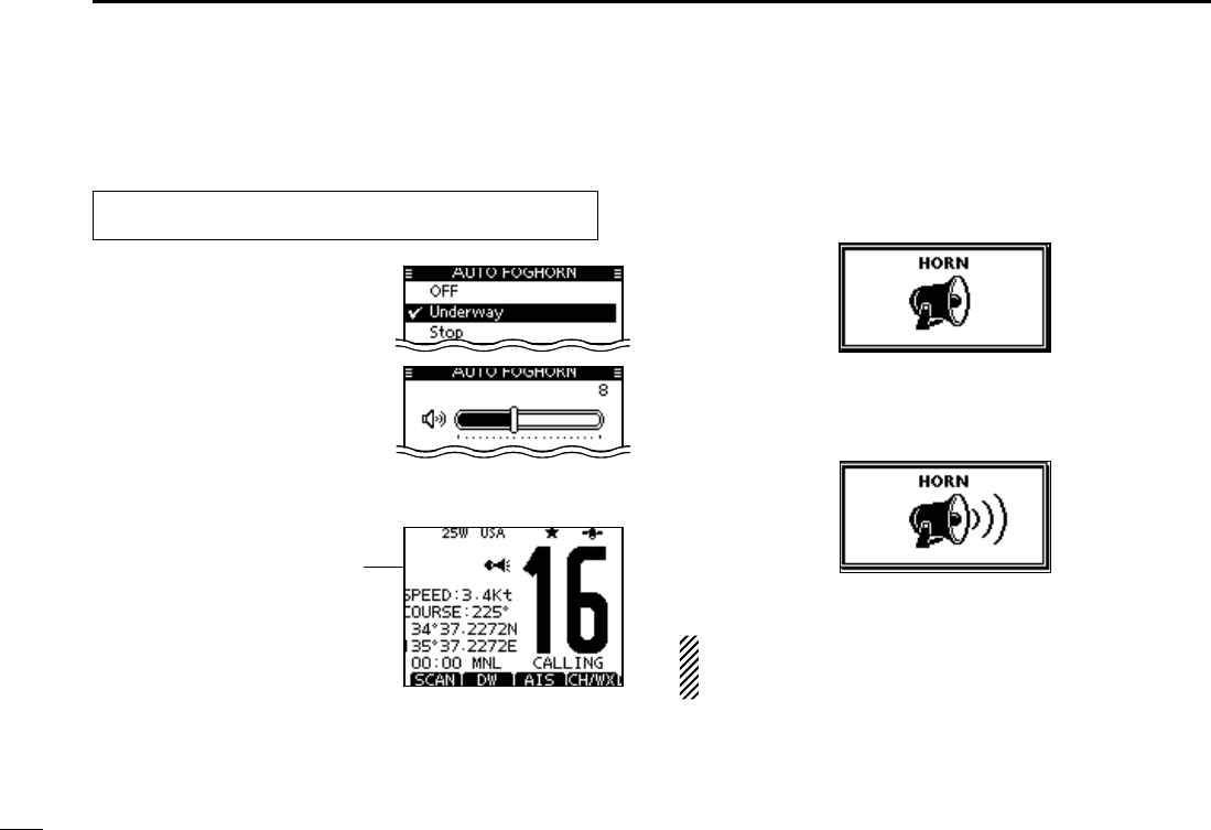
77
8OTHER FUNCTIONS
q Enter “Auto Foghorn” in the HORN menu. D Manual Horn function
q Push [HORN] to enter the Horn mode.
w Hold down [HORN] to sound a horn.
s7HILEHOLDINGDOWN;(/2.=THEHORNSOUNDSANDTHESCREEN
below is displayed.
s4OADJUSTTHEHORNVOLUMELEVELROTATE$IAL
e Push [EXIT] to return to the normal operating screen.
While in the Horn mode, the transmit and receive functions
are disabled. When the transceiver is transmitting, the
Horn function is disabled.
eMENUf ¶ eHORNf ¶ eAuto Foghornf
(Push [MENU]) (Select icon)
(Rotate Dial, then push [ENT].)
Appears
w Rotate dial or push [Y]/[Z] to
select the desired foghorn pat-
tern, and then push [ENT}.
e Rotate dial or push [Y]/[Z] to
adjust the foghorn level.
s4HEFOGHORNLEVELISADJUSTABLEIN
20 steps.
r Push [MENU] to exit the MENU
screen.
s4HEHORNICONISDISPLAYED
t To return to normal operation,
select [OFF] in the Auto Fog-
horn menu.
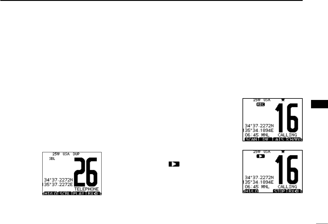
78
8
OTHER FUNCTIONS
1
2
3
4
5
6
7
8
9
10
11
12
13
14
15
16
N Voice scrambler operation
The voice scrambler provides private communications. In
order to receive or send scrambled transmissions, you must
activate the scrambler function. You also need to program
the scrambler code in the Menu screen. (p.98)
q
Select an operating channel except Channel 16, 70 or
weather channels.
w
Push to turn the Voice Scrambler ON or OFF.
s4HE)CONAPPEARSWHENTHEVOICESCRAMBLERIS/.
D Programming scrambler codes
There are 32 codes (1 to 32) available for programming. Set
the code in the SET mode. In order to understand each other,
all transceivers in your group must have the same scramble
code, as well as the same scrambler unit. See page 98 for
scrambler code setting details.
Voice recorder function N
This transceiver has automatic recording function which can
record the last 120 seconds of the receiving signal.
This voice recorder uses EEPROM to save the recorded
voice data. EEPROM needs to be changed when it is used
more than 30,000 hours. Contact your Icom dealer or distrib-
uter for advice.
q Start recording automatically
when the signal is received.
s;2%#=APPEARSWHILERECORDING
s3TOP recording 3 seconds after
the signal is lost.
w Push [PLAY] to play back the
recorded voice.
s appears while playing.
e Push [STOP] to return to nor-
mal operating screen.
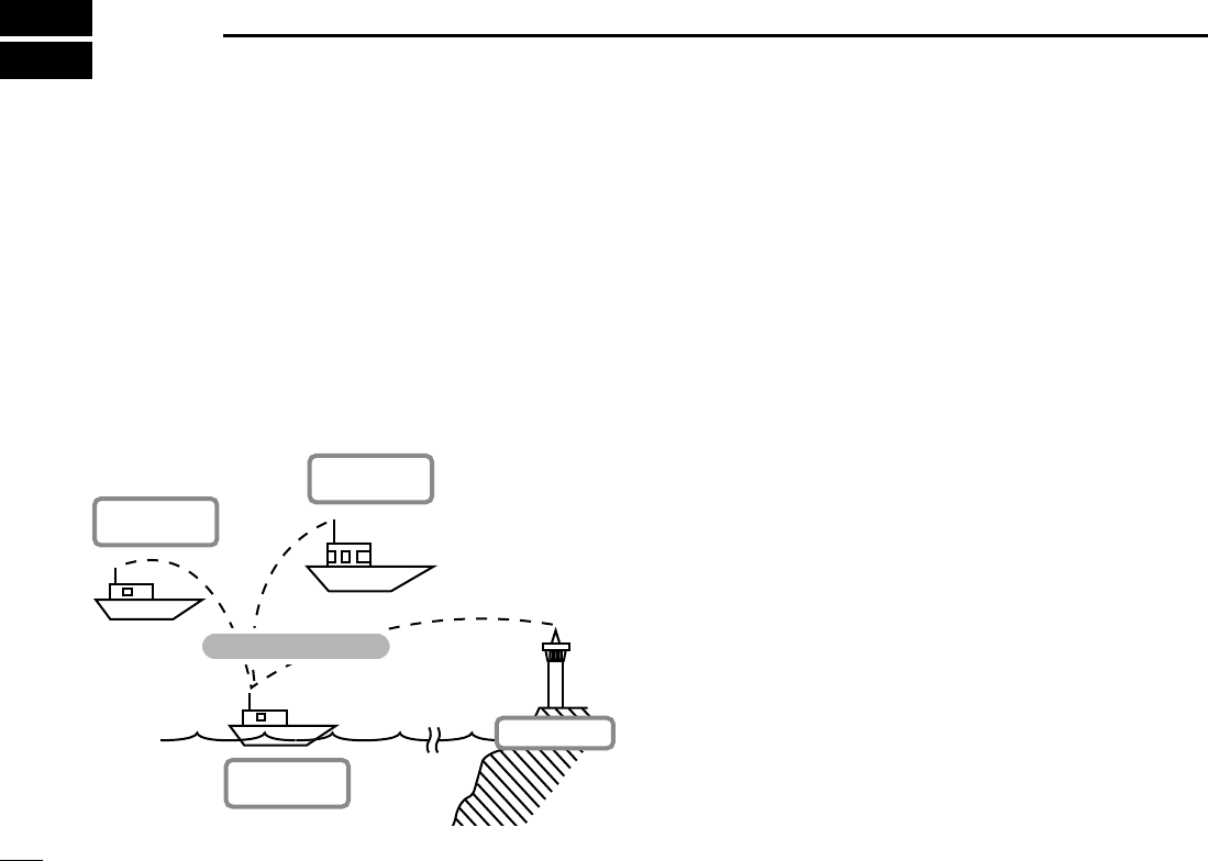
79
AIS Receiver (Depending on versions)
9
About AIS N
AIS (The automatic identification system) used primarily for
collision-risk management and navigation safety. It automati-
cally transmits and receives vessel information such as the
vessel name, MMSI code, vessel type, position data, speed,
course, destination and more. Information is exchanged
among the vessels and/or base stations on the VHF maritime
mobile band. The information helps to identify other nearby
vessels or stations by displaying the received data on
a plotter or a radar screen.
AIS Classes N
There are seven types of AIS stations; vessels, base stations,
Search and Rescue (SAR), Aids to Navigation (AtoN), Search
and Rescue Transmitter (AIS-SART), MOB (Man OverBoard)
and EPIRB (Emergency Position Indicating Radio Beacon)-
AIS.
There are two classes of AIS units, which are installed on
vessels; Class A and Class B.
Under the Safety Of Life At Sea (SOLAS) convention, all
SOLAS vessels, as described below, are required to install a
Class A AIS transponder:
s5PWARDS OF GROSS TONNAGE ENGAGED ON INTERNATIONAL-
voyages.
s0ASSENGERVESSELSIRRESPECTIVEOFSIZEENGAGEDONINTENA-
tional voyages.
s5PWARDSOFGROSSTONNAGENOTENGAGEDONINTERNATIONAL
voyages.
A Class B AIS transponder is designed to be interoperability
with Class A units, but not to impact the Class A network.
Many commercial vessels, and some leisure craft, not clas-
sified as requiring a Class A unit, choose to install a Class B
unit to avoid accidents at sea.
Your vessel
(Class B AIS)
Other vessel
(Class A AIS)
Other vessel
(Class B AIS)
Base Station
Vessel information

80
9
AIS Receiver (Depending on versions)
Function display N
There are three display types; plotter, target list and danger
list, and you can select your desired type using the [DISP]
key.
q Push [MENU].
w
Select AIS in the menu screen.
s!)3PLOTTERAPPEARSONTHEDISPLAY
e
Push [Y](CH) or [Z](CH) to adjust the plotter range.
D Plotter display
After select AIS in the menu screen, the plotter display appears.
If the GPS is connected and it receives signals from a satellite. It
shows the display range and the icons of the AIS targets.
q DISPLAY TYPE
Shows the selected display type. You can select the dis-
play type from “AIS SET” in the menu screen (P.87)
s7HENh.50vISDISPLAYEDTHETOPOFTHEPLOTTERDISPLAYREPRE-
sents North.
s7HENh!#50vISDISPLAYEDTHETOPOFTHEPLOTTERDISPLAYREPRE-
sents the direction your course is heading.
w RANGE/CPA INFORMATION
± Shows the range information from your vessel to the se-
lected AIS target.
± Shows the CPA (Closest Point of Approach) information
of the selected AIS target whose CPA is within 6 nm
(nautical miles) and TCPA (Time to CPA) is within 60
minutes of your vessel.
e BEARING/TCPA INFORMATION
± Shows the bearing information from your vessel to the
selected AIS target.
± Shows TCPA information of the selected AIS target
whose CPA is within 6 nm (nautical miles) and TCPA is
within 60 minutes of your vessel.
r TARGET BOX
Shows the selected AIS target.
s7HEN A TARGET BOX APPEARS PUSH [ENT] to display the detail
screen of the selected AIS target.
1
2
3
4
6
7
8
10
11
12
13
14
15
16
r
y
t
q
e
w
4
9
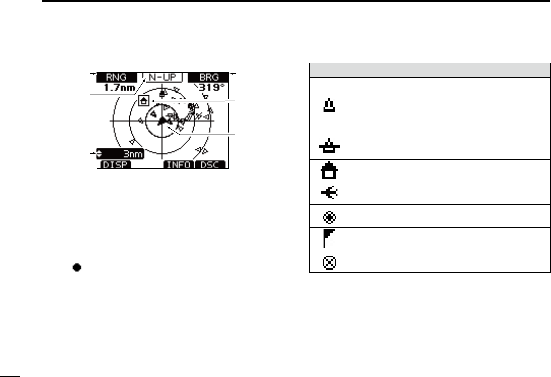
81
9AIS Receiver (Depending on versions)
r
y
t
q
e
w
t YOUR VESSEL ICON
Your
vessel icon is displayed in the center of the display.
s7HENh.50vISDISPLAYEDTHEVESSELICONAUTOMATICALLYPOINTS
in the direction you are heading, in 45 degrees steps.
s7HENh!#50vISDISPLAYEDTHEVESSELICONCONSTANTLYPOINTSTO
the top of the plotter display.
s7HENYOURVessel moves less than 2 knots, the icon is displayed
as “ .”
y DISPLAY RANGE
Shows the selected display range.
± Push [∫](CH) or [√](CH) to select display range.
sNMNAUTICALMILESARE
selectable.
s$ESCRIPTIONOFTHEICONS
Icon Description
AIS target: Vessel
The tip of the target triangle automatically points
in the direction it’s heading.
The icon blinks when the AIS target is closer than
your CPA and TCPA settings. (Dangerous target)
AIS target: Lost target*
The target triangle is marked with a diagonal line.
AIS target: Base Station
AIS target: Search and Rescue (SAR)
AIS target: Aids to Navigation (AtoN)
Waypoint
AIS target: AIS-SART, MOB and EPIRB-AIS
* A vessel is regarded as a “Lost target” after a specified period
of time has passed since the vessel last transmitted data.
The “Lost target” icon disappears from the plotter display 6
minutes and 40 seconds after the vessel was regarded as a
“Lost target.” Ask your dealer for details.
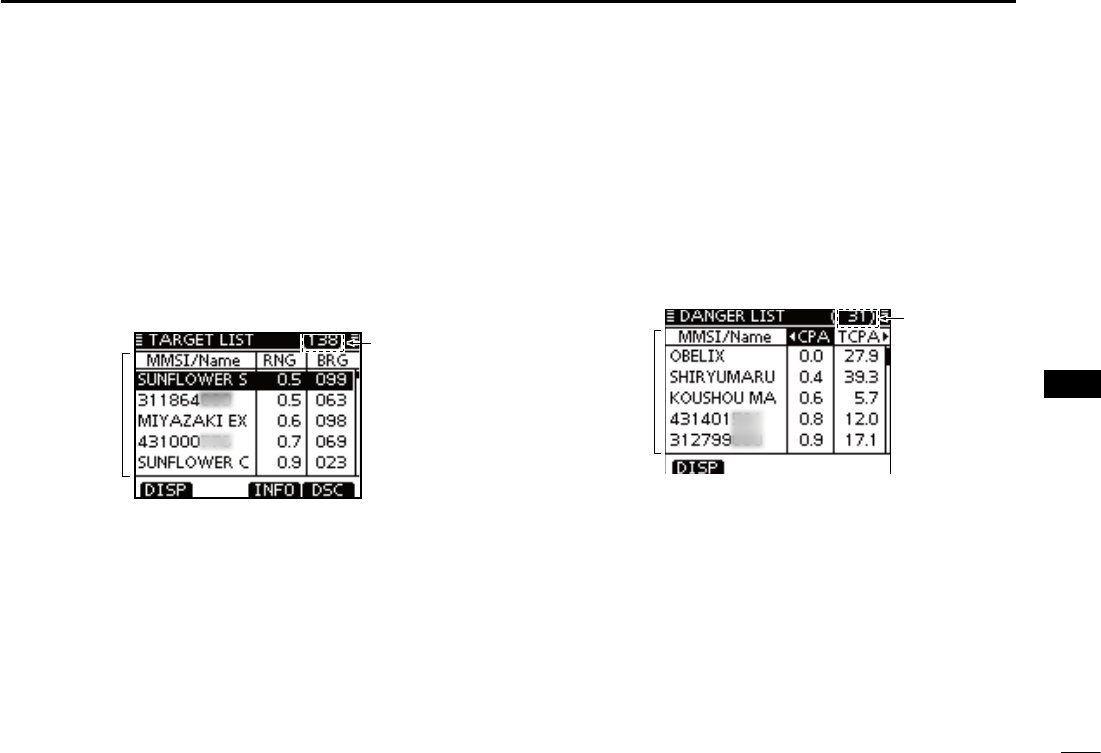
82
9
AIS Receiver (Depending on versions)
1
2
3
4
5
6
7
8
9
10
11
12
13
14
15
16
D Target list display
In the plotter display, push [DISP] to switch to the target list
display, which shows all AIS targets being detected by the
transponder.
The AIS target data is sorted by the distance from your ves-
sel, and the closest target is located on the top of the list.
s Push [∫] or [√] to select an AIS target.
s Push [INFO] to display the detail screen of the selected AIS tar-
get. (p. 83)
s Push [DSC] to transmit DSC call to selected AIS target.
q
w
q THE NUMBER OF TARGETS
Shows the number of AIS targets which are being detected
by the transponder.
w TARGET INFORMATION
Shows the following AIS target information:
s--3)CODEORNAME, if the name is programmed.
s2ANGE2.'FROMYOURVESSELTOTHETARGETUNITNAUTICALMILE
s"EARING"2'FROMYOURVESSELTOTHETARGETUNITDEGREE
D Danger list display
In the target list display, push [DISP] to switch to the dan-
ger list display, which helps you to find any dangerous target
whose CPA is within 6 nm (nautical miles) and TCPA is within
60 minutes of your vessel.
s Push [∫] or [√] to select an AIS target.
s Push [INFO] to display the detail screen of the selected AIS tar-
get. (p. 83)
q
w
q THE NUMBER OF DANGEROUS TARGETS
Shows the number of AIS targets which are being detected
by the transponder.
w DANGER TARGET INFORMATION
Shows the following dangerous target information:
s--3)CODEORNAME, if the name is programmed.
s#0! #LOSEST0OINTOF!PPROACHUNITNAUTICALMILE
s4#0!4IMETO#0!UNITMINUTE
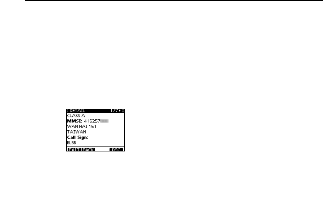
83
9AIS Receiver (Depending on versions)
About the detail screen N
The detail screen shows information about the
selected AIS target. The contents differ, depending on
the AIS class.
In the detail screen, pushing [CLEAR] returns to the
previous screen, which was displayed before entering
the details screen.
s Push [CLEAR] returns to the previous screen.
s Rotate Dial or push [Ω]/[≈] to scroll the page.
Example of detail screen
D Content lists of Class A vessels’ DETAIL
screens
s!)3#LASS
s--3)#ODE
s3HIP.AME
s#OUNTRY.AME
s#ALL3IGN
s)-/.UMBER
s#0! #LOSEST 0OINT OF
approach
s4#0!TIMETO#0!
s0OSITION,ATITUDE
Longitude)
s3PEED/VER'ROUND
s#OURSE/VER'ROUND
s(EADING
s0OSITION!CCURACY
(H: High, L: Low)
s2ANGE
s"EARING
s2ATE/F4URN
s"OWTO!NTENNALENGTH
s3TERNTO!NTENNALENGTH
s0ORTSIDETO!NTENNA
length
s Starboard side to
Antenna length
s,ENGTH
s"EAM
s$RAUGHT
s4YPEOF3HIP
s.AVIGATION3TATUS
s$ESTINATION
s$ATE
s4IME

84
9
AIS Receiver (Depending on versions)
1
2
3
4
5
6
7
8
9
10
11
12
13
14
15
16
D Content lists of Class B vessels’ DETAIL
screens
s!)3#LASS
s--3)#ODE
s3HIP.AME
s#OUNTRY.AME
s#ALL3IGN
s6ENDOR)$
s#0! #LOSEST 0OINT OF
approach
s4#0!TIMETO#0!
s0OSITION,ATITUDE
Longitude)
s3PEED/VER'ROUND
s#OURSE/VER'ROUND
s(EADING
s0OSITION!CCURACY
(H: High, L: Low)
s2ANGE
s"EARING
s"OWTO!NTENNALENGTH
s3TERNTO!NTENNALENGTH
s0ORTSIDETO!NTENNA
length
s Starboard side to
Antenna length
s,ENGTH
s"EAM
s4YPEOF3HIP
D Content lists of Base Station targets’ DE-
TAIL screens
s!)3#LASS
s--3)#ODE
s0OSITION,ATITUDE
Longitude)
s0OSITION!CCURACY
(H: High, L: Low)
s2ANGE
s"EARING
D Content lists of SAR targets’ DETAIL
screens
s!)3#LASS
s--3)#ODE
s0OSITION,ATITUDE
Longitude)
s3PEED/VER'ROUND
s#OURSE/VER'ROUND
s0OSITION!CCURACY
(H: High, L: Low)
s2ANGEs"EARING
s!LTITUDE
D Content lists of AtoN targets’ DETAIL
screens
s"OWTO!NTENNALENGTH
s3TERNTO!NTENNALENGTH
s0ORTSIDETO!NTENNA
length
s Starboard side to
Antenna length
s,ENGTHs"EAM
s0OSITION)NDICATOR
( ON POS : ON Position,
OFF POS : OFF Position)
s!TO.EXISTENCE
(REAL, VIRTUAL)
s4YPEOF!TO.
s$ESCRIPTIONOF!TO.

85
9AIS Receiver (Depending on versions)
D Content lists of AIS-SART targets’ DETAIL
screens
s4YPEOF!)34ARGET
s--3)#ODE
s#ALL3IGN
s)-/.UMBER
s#LOSEST0OINTOF
Approach
s4#0!TIMETO#0!
s0OSITION,ATITUDE
Longitude)
s3PEED/VER'ROUND
s#OURSE/VER'ROUND
s(EADING
s0OSITION!CCURACY
(H: High, L: Low)
s2ANGE
s"EARING
s2ATE/F4URN
s"OWTO!NTENNALENGTH
s3TERNTO!NTENNALENGTH
s0ORTSIDETO!NTENNA
length
s Starboard side to
Antenna length
s,ENGTH
s"EAM
s$RAUGHT
s4YPEOF3HIP
s.AVIGATION3TATUS
s$ESTINATION
s$ATE
s4IME
D Content lists of MOB targets’ DETAIL
screens
s4YPEOF!)34ARGET
s--3)#ODE
s#ALL3IGN
s)-/.UMBER
s#LOSEST0OINTOF
Approach
s4#0!TIMETO#0!
s0OSITION,ATITUDE
Longitude)
s3PEED/VER'ROUND
s#OURSE/VER'ROUND
s(EADING
s0OSITION!CCURACY
(H: High, L: Low)
s2ANGE
s"EARING
s2ATE/F4URN
s"OWTO!NTENNALENGTH
s3TERNTO!NTENNALENGTH
s0ORTSIDETO!NTENNA
length
s Starboard side to
Antenna length
s,ENGTH
s"EAM
s$RAUGHT
s4YPEOF3HIP
s.AVIGATION3TATUS
s$ESTINATION
s$ATE
s4IME

86
9
AIS Receiver (Depending on versions)
1
2
3
4
5
6
7
8
9
10
11
12
13
14
15
16
D Content lists of EPIRB-AIS targets’ DETAIL
screens
s4YPEOF!)34ARGET
s--3)#ODE
s#ALL3IGN
s)-/.UMBER
s #LOSEST 0OINT OF !P-
proach
s4#0!TIMETO#0!
s0OSITION,ATITUDE
Longitude)
s3PEED/VER'ROUND
s#OURSE/VER'ROUND
s(EADING
s0OSITION!CCURACY
(H: High, L: Low)
s2ANGE
s"EARING
s2ATE/F4URN
s"OWTO!NTENNALENGTH
s3TERNTO!NTENNALENGTH
s0ORTSIDETO!NTENNA
length
s Starboard side to
Antenna length
s,ENGTH
s"EAM
s$RAUGHT
s4YPEOF3HIP
s.AVIGATION3TATUS
s$ESTINATION
s$ATE
s4IME
D AIS combo display
AIS plotter can be displayed in transceiver mode.
q
Push [AIS] to display
AIS plotter on the left side of screen
.
± Push [∫](CH) or [√](CH) to select an operating chan-
nel.
± Push [Ω] and [≈] or [Ω] and [≈] to select vessel.
s
A soft key [INFO] will appear.
± Push [INFO] or [ENT] to display the detail screen of the
selected AIS target.
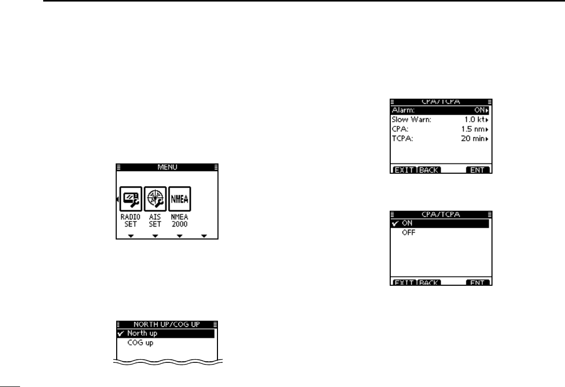
87
9AIS Receiver (Depending on versions)
AIS Settings N
AIS settings can be customized from “AIS SET” in the menu
screen..
q Push [MENU].
w
Rotate Dial or push [Ω]/[≈] to select “AIS SET” icon and
then push the soft key below the icon.
s!)3SETTINGSMENUAPPEARSONTHEDISPLAY
D.ORTHUP#/'50
Select the display type for AIS plotter.
s7HENh.ORTHUPvISDISPLAYEDTHETOPOFTHEPLOTTERDISPLAYREP-
resents North.
s7HENh#OGUPvISDISPLAYEDTHETOPOFTHEPLOTTERDISPLAYREPRE-
sents the direction your course is heading.
D CPA/TCPA
In this menu, you can edit alarm settings for AIS receiver.
s!LARM
You can turn the collision alarm function ON or OFF.
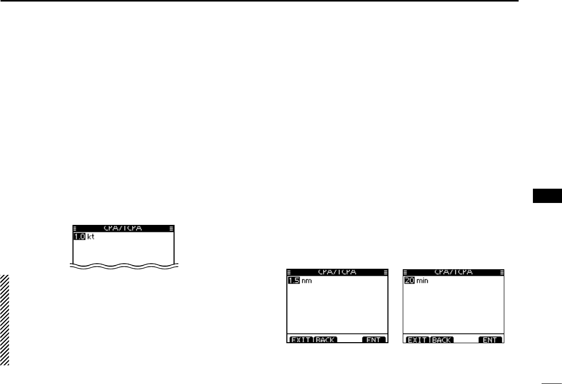
88
9
AIS Receiver (Depending on versions)
1
2
3
4
5
6
7
8
9
10
11
12
13
14
15
16
s3LOW7ARN
The GPS receiver calculated COG data of a vessel that is at
anchor or drifting is unreliable, and therefore the CPA and
TCPA data may not be calculated correctly. If a vessel is an-
chored in your alarm zone, the unreliable data can cause the
collision alarm to sound many times, even if there is no real
danger. To prevent this, when the anchored vessel’s SOG is
less than this set value, the Slow Warn function assumes that
vessel’s COG is fixed towards your vessel and an alarm will
sound.
q
Push [Y](CH) or [Z](CH) to input the value between 0.1
and 4.9 kt (in 0.1 kt steps), or select OFF. (default: 1.0 kt)
w Push [ENT] to save and return to the Menu mode.
NOTE: If other vessels at anchor or drifting come into your
alarm zone, the Slow Warn alarm will sound again. Only if
the previous vessel disappears from the Dangerous List
(p. 82), and then re-enters the list, can a new Slow Warn
or regular alarm sound, depending on the vessels SOG,
or CPA and TCPA. The Slow Warn function operates in the
same way if your vessel is at anchor and other vessels
enter your alarm zone area.
s#0!4#0!
Enter CPA (Closest Point of Approach) and TCPA (Time to
CPA) values.
These settings help you find a dangerous target to avoid a
collision. The icon blinks on the plotter display and/or the
alarm buzzer sounds, when the AIS target is closer than your
CPA and TCPA settings.
q
Push [Y](CH) or [Z](CH) to select either “CPA” or “TCPA.”
s#0!OR4#0!SETTINGMENUAPPEARSONTHEDISPLAY
w
Push [Y](CH) or [Z](CH) to input the value into that item.
s#0!"ETWEENANDNMINNMSTEPS
(default: 1.5 nm)
s4#0!"ETWEENANDMINUTESINMINUTESTEPS
(default: 20 min)
e
Repeat steps
q
and w to input the value into the other
item.
r Push [CLEAR] to save and return to the Menu mode.
When the CPA setting
menu is selected.
When the TCPA setting
menu is selected.
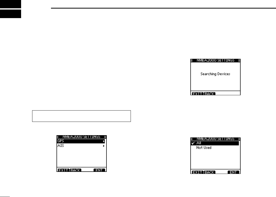
89
NMEA 2000 Connection (Depending on versions)
10
Description N
NMEA 2000 is a communication standard used for connect-
ing various marine censors and display units in the vessel.
IC-M506 can easily connect to a NMEA 2000 network with its
plug-and-play functionality and display the information pro-
vided from the devices in the network.
D NMEA 2000 settings
Select the censors in NMEA 2000 network which sends data
to the transceiver.
q Enter “NMEA 2000”menu in the menu screen.
w Select the type of data from the menu screen and push
[ENT].
w The transceiver starts searching the devices connected to
NMEA 2000 network.
e The list of connected censor is displayed.
r Select the censor to send the data to transceiver and push
[ENT].
s3ELECTh.OT 5SEDvIF THETRANSCEIVERIS RECEIVING THEDATA FROM
the censor with NMEA 0183. The transceiver uses the data from
NMEA 2000 if it is received from both network.
t Push [MENU] to exit the MENU screen.
eMENUf ¶ eNMEA 2000f
(Push [MENU]) (Select icon)
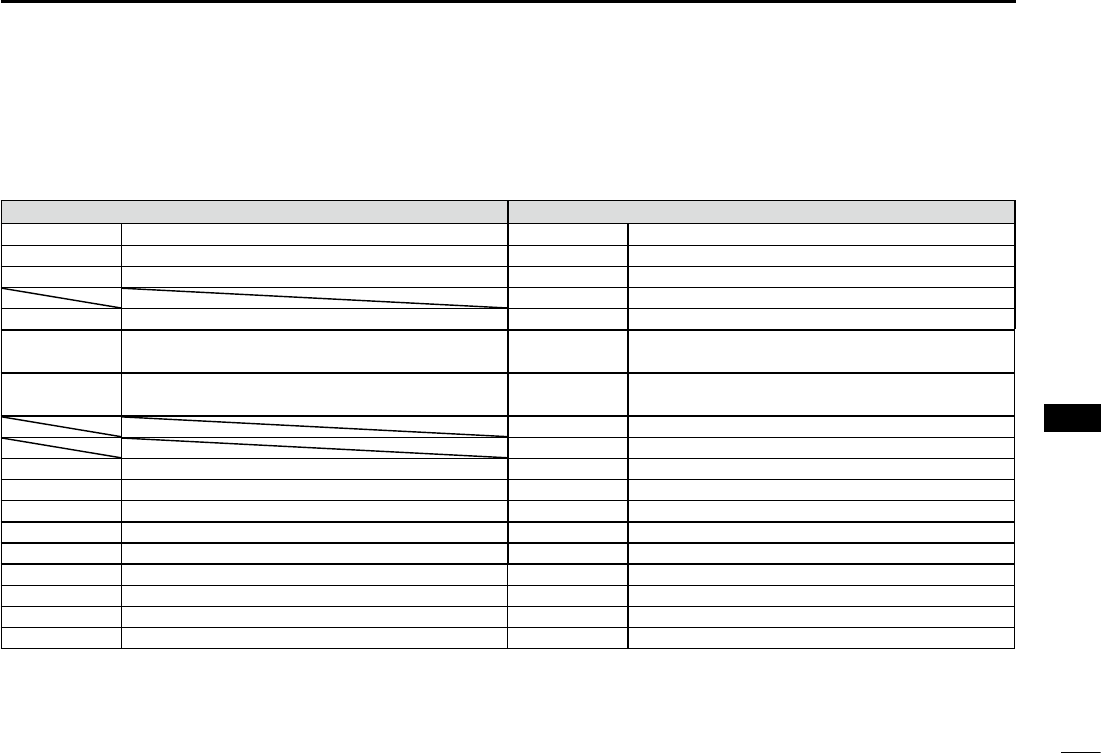
90
10
NMEA 2000 Connection (Depending on versions)
1
2
3
4
5
6
7
8
9
10
11
12
13
14
15
16
D Compatible PGN list
Receive Transmit
059392 ISO Acknowledgement 059392 ISO Acknowledgement
059904 ISO Request 059904 ISO Request
060928 ISO Address Claim 060928 ISO Address Claim
126464 PGN List
126996 Product Information 126996 Product Information
129026 COG (course over ground) and SOG (speed
over ground) - Rapid Update
129026 COG (course over ground) and SOG (speed
over ground) - Rapid Update
129029 GNSS (Global Navigation Satellite System)
Position Data
129029 GNSS (Global Navigation Satellite System)
Position Data
129799 Radio Frequency/Mode/Power
129808 DSC Call Information
129038 AIS Class A Position Report 129038 AIS Class A Position Report
129039 AIS Class B Position Report 129039 AIS Class B Position Report
129040 AIS Class B Extended Position Report 129040 AIS Class B Extended Position Report
129041 AIS Aids to Navigation (A to N) Report 129041 AIS Aids to Navigation (A to N) Report
129793 AIS UTC and Date Report (Base Station) 129793 AIS UTC and Date Report (Base Station)
129794 AIS Class A Static and Voyage Related Data 129794 AIS Class A Static and Voyage Related Data
129798 AIS SAR Aircraft Position Report 129798 AIS SAR Aircraft Position Report
129809 AIS Class B "CS" Static Data Report, Part A 129809 AIS Class B "CS" Static Data Report, Part A
129810 AIS Class B "CS" Static Data Report, Part B 129810 AIS Class B "CS" Static Data Report, Part B
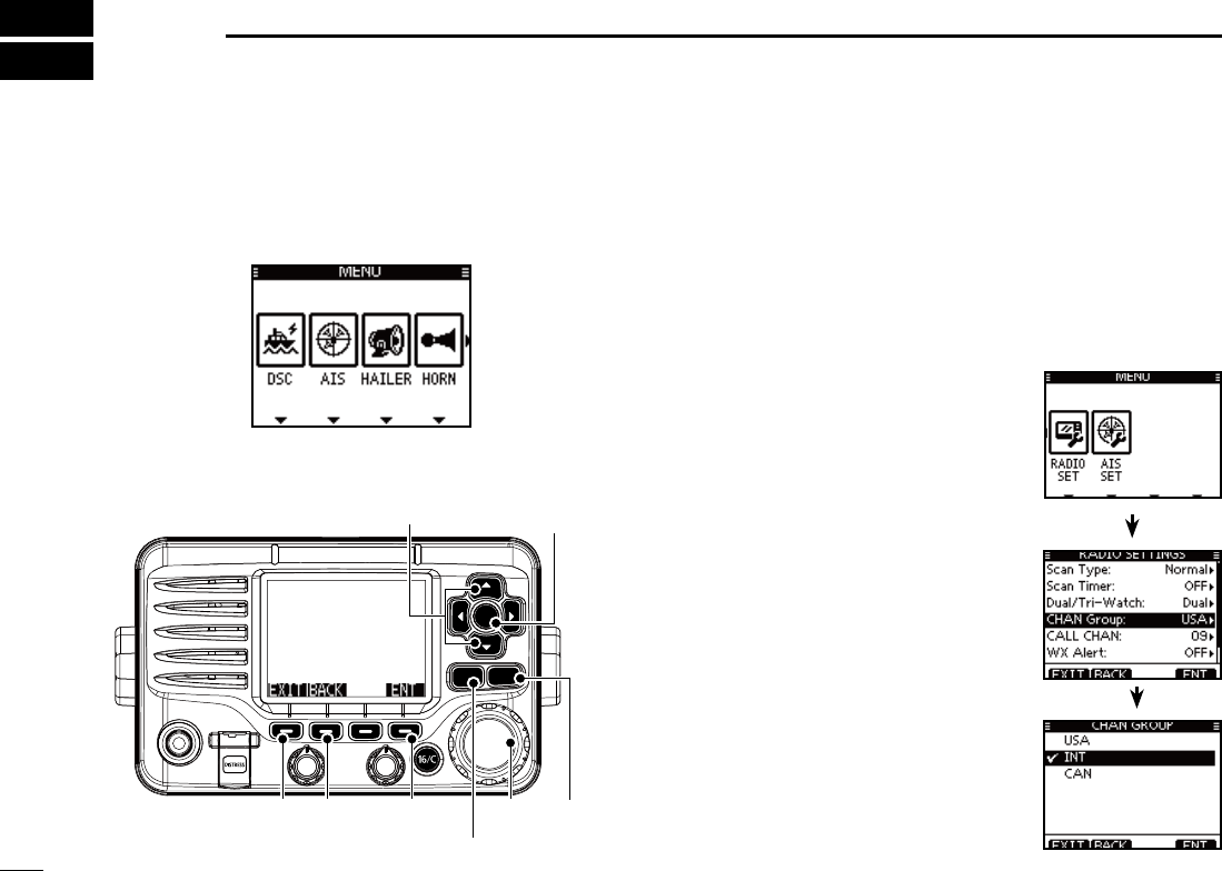
91
MENU SCREEN OPERATION
11
NMenu screen operation
The Menu screen is used for programming infrequently
changed values, function settings or sending DSC calls.
DEntering the Menu screen and operation
%XAMPLE Set the channel group to “INT.”
q Push [MENU].
w Rotate Dial or push [Ω]/[≈] to select
“RADIO SET” icon and then push
the soft key below the icon.
e Rotate Dial or push [∫]/[√] to se-
lect “CHAN Group,” and then push
[ENT].
Rotate Dial or push [ r∫]/[√] to select
“USA,” and then push [ENT] to set it.
sh” is displayed next to “INT.”
t
Push [EXIT] to exit the Menu screen.
s0USH ;#,%!2= OR ;"!#+= TO RETURN TO
the previous screen.
CLEARMENU
ENT
CH
CH
[ENT]
[Y]/[Z]
[CLEAR][EXIT] [ENT][BACK] Dial
[MENU]
Menu icons
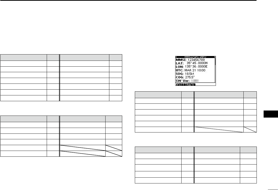
92
11
MENU SCREEN OPERATION
1
2
3
4
5
6
7
8
9
10
11
12
13
14
15
16
Menu screen items N
The Menu screen contains the following items.
DSC D
Item Ref. Item Ref.
s)NDIVIDUAL#ALL p. 28
s0OSITION2EQUEST
p. 37
s)NDIVIDUAL!#+1p. 31
s
Position Reply p. 47
s'ROUP#ALL p. 33
s
Position Report p. 39
s!LL3HIPS#ALL p. 35
s
Polling Request p. 41
s$ISTRESS#ALL p. 23 s0OLLING2EPLY p. 51
s2ECEIVED#ALL,OG p. 65 s4EST#ALL p. 43
s
Transmitted Call Log
p. 67 s4EST!#+1p. 45
D CONFIG (Configuration)
Item Ref. Item Ref.
s"ACKLIGHT p. 93 s(ORN&REQUENCY p. 95
s$ISPLAY#ONTRAST p. 93 s)NACTIVITY4IMER p. 95
s+EY"EEP p. 93 s5NIT)$ p. 96
s+EY!SSIGNMENT p. 94 s#/--!.$-)#303p. 96
s+EY-OVEMENT p. 94
s54#/FFSET p. 94
*1 Appears only after receiving a corresponding call.
*2 Appears only when no GPS information is received.
*3 Appears only when the optional HM-195 is connected.
*4 Appears only when a GPS receiver compatible with NMEA0183
ver. 2.0 and 3.01 or NMEA 2000 is connected.
D MMSI/GPS
The transceiver shows the programmed MMSI code and GPS
information*4.
If the code is not programmed, “NO DSC MMSI” is displayed.
DSC SET D
Item Ref. Item Ref.
s0OSITION)NPUT2p. 22 s#(3WITCH p. 69
s)NDIVIDUAL)$ p. 19 s$3#$ATA/UTPUT p. 70
s'ROUP)$ p. 20 s!LARM3TATUS p. 70
s)NDIVIDUAL!#+ p. 68 s#(31,,EVEL p. 71
s0OSITION!#+ p. 68 s$3#,OOP4EST p. 71
s4EST!#+ p. 68
D RADIO SET
Item Ref. Item Ref.
s3CAN4YPE p. 97 s78!LERT2p. 98
s3CAN4IMER p. 97 s6OICE3CRAMBLER p. 98
s$UAL4RI7ATCH p. 97 s.OISE#ANCEL p. 99
s#(!.'ROUP p. 97 s6OICE2ECORD p. 100
s#!,,#(!. p. 98 s&!6ON-)# p. 100
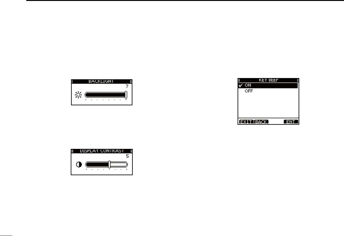
93
11 MENU SCREEN OPERATION
Configuration items N
D Backlight
The function display and keys can be backlit for better visibil-
ity under low light conditions.
The backlight can be set to 7 levels and OFF. (Default: 7)
D Display contrast
This item adjusts the contrast of the LCD in 8 steps.
Level 1 is the lowest contrast, and level 8 is the highest con-
trast. (Default: 5)
D Key Beep
You can turn OFF beep tones for silent operation, or you can
turn ON the tones to have confirmation beeps sound when a
key is pushed. (Default: ON)
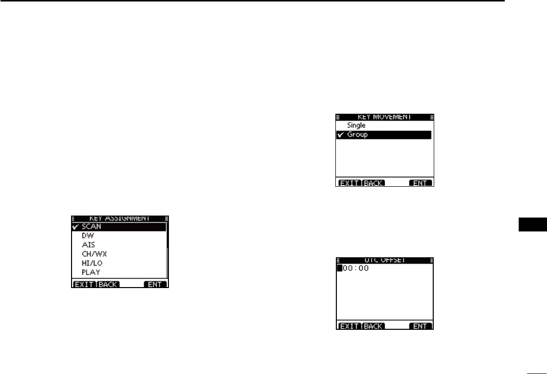
94
11
MENU SCREEN OPERATION
1
2
3
4
5
6
7
8
9
10
11
12
13
14
15
16
D Key Assignment
Desired functions can be assigned to soft keys.The assigned
function can be used when its key icon is displayed.
See page 3 for details of the assignable key functions.
q Rotate Dial or push [∫]/[√] to select the desired position,
and then push [ENT].
s4ORETURNTOTHEDEFAULTSELECTh3ETDEFAULTvANDPUSH;%.4=
w Rotate Dial or push [∫]/[√] to select the option, and then
push [ENT] to set it.
sh” is displayed next to the selected option.
* [CHAN] appears instead of [CH/WX] only for Chinese version
transceiver.
e Push [EXIT] to exit the Menu screen.
s0USH;#,%!2=OR;"!#+=TORETURNTOTHEPREVIOUSSCREEN
D Key Movement
Set the movement of soft key icons and menu icons. You can
select from 2 types of movement, “Single” or “Group”.
UTC Offset D
Set the offset time between the UTC (Universal Time Coordi-
nated) and your local time to between –14:00 and +14:00 (in
1 minute steps). (Default: 00:00)
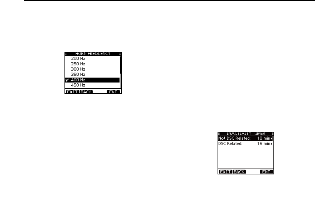
95
11 MENU SCREEN OPERATION
D Horn Frequency
Set audio frequency of the foghorn.
s!VAILABLEFREQUENCYRANGEIS(ZTO(ZIN(ZSTEPS
D Inactivity Timer
Set the inactivity timer to between 1 and 10 minutes (in 1 min-
ute steps) or OFF for the “Not DSC Related” and “DSC Re-
lated” item, and set to between 1 and 15 minutes (in 1 minute
steps) or OFF for the “DSC Related” item. The count down
alarm sounds 10 seconds before the Inactive timer returns
the current screen to the normal operating screen.
When the “INACTIVITY TIMER” screen is displayed, rotate q
Dial or push [∫]/[√] to select “Not DSC Related” or “DSC
Related,” and then push [ENT].
Rotate Dial or push [ w∫]/[√] to select the option, and then
push [ENT] to set it.
sh” is displayed next to the selected option.
Push [EXIT] to exit the Menu screen. e
s0USH;#,%!2=OR;"!#+=TORETURNTOTHEPREVIOUSSCREEN
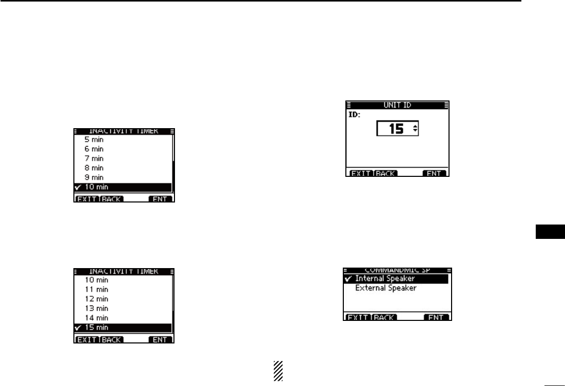
96
11
MENU SCREEN OPERATION
1
2
3
4
5
6
7
8
9
10
11
12
13
14
15
16
s.OT$3#2ELATED
When the LCD displays a screen other than the normal opera-
tion screen, or one not related to the DSC, and no key opera-
tion occurs for this set period, the transceiver automatically
returns to the normal operating screen.
(Default: 10 min)
s$3#2ELATED
When the LCD displays the screen related to the DSC, and no
key operation occurs for this set period, the transceiver automati-
cally returns to the normal operating screen.
(Default: 15 min)
Unit ID D
Set a Unit ID number to between 1 and 69. (Default: 15)
The Unit ID is included in the sentence of the Icom original
NMEA format.
COMMANDMIC Speaker D
(Appears only when the optional HM-195 is connected.)
The HM-195’s external speaker can be used instead of the
internal speaker.
Internal Speaker : Turns ON the internal speaker. (Default)
External Speaker : Turns ON the external speaker.
Regardless of this setting, the supplied microphone’s
speaker is ON.
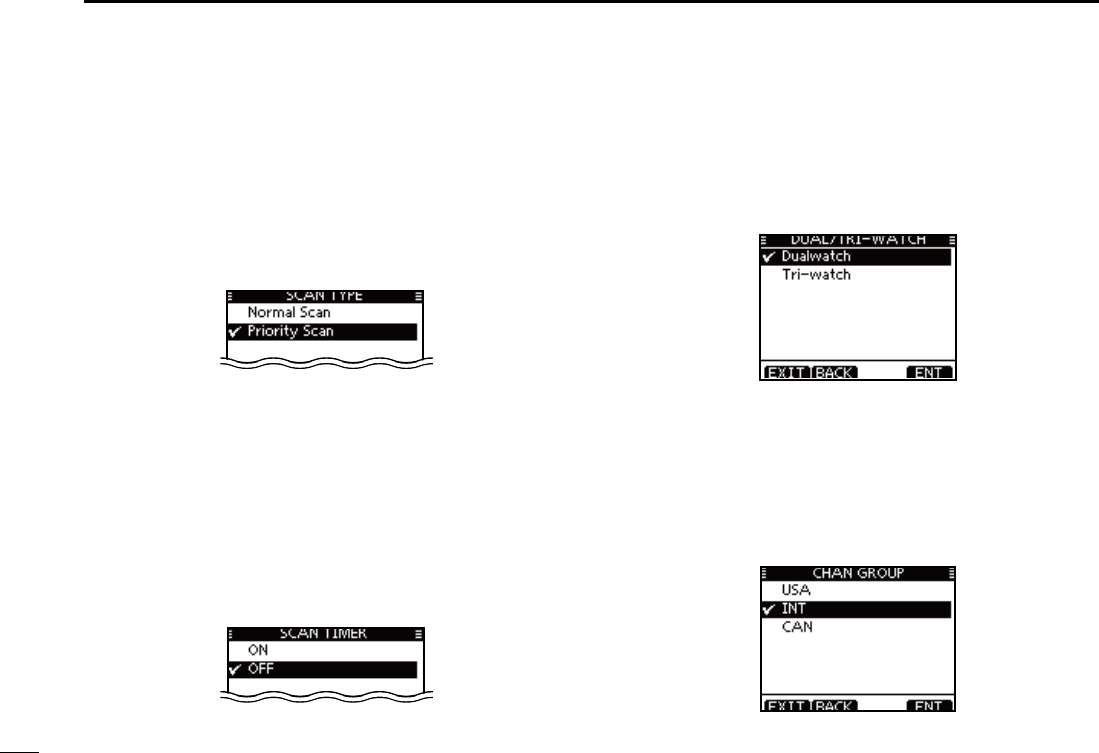
97
11 MENU SCREEN OPERATION
Radio Settings items N
D Scan Type
The transceiver has two scan types; Normal scan and Priority
scan. A Normal scan searches all Favorite channels in the
selected channel group. A Priority scan sequentially searches
all Favorite channels, while monitoring Channel 16.
(Default: Priority Scan)
D Scan Timer
The scan resume timer can be selected as a pause (OFF)
or timer scan (ON). When OFF is selected, the scan pauses
until the signal disappears. (Default: OFF)
s Priority scan
When ON is selected, the scan pauses for 5 sec-
onds and then resumes, even if a signal has been
received on any channel other than Channel 16.
s.ORMALSCAN When ON is selected, the scan pauses for 5
seconds and then resumes, even if a signal has
been received on any channel.
Dual/Tri-watch D
This item can be selected as Dualwatch or Tri-watch. (p. 18)
(Default: Dualwatch)
D Channel Group
Except for the Europe version, a channel group suitable for
your operating area can be selected. Depending on the trans-
ceiver version, INT, USA or CAN may be selectable.
(Default: USA)
See page 10 for details.
s4HESCREENBELOWSHOWSTHE53!VERSION
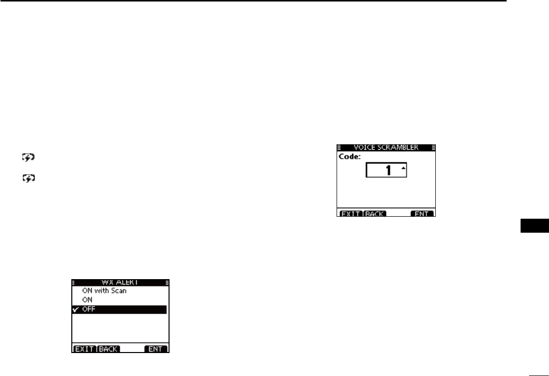
98
11
MENU SCREEN OPERATION
1
2
3
4
5
6
7
8
9
10
11
12
13
14
15
16
D CALL CHAN (Call channel)
You can program the Call channel with your most often-used
channel in each channel group for quick recall. (p.13)
D WX alart (Weather alert)
A NOAA broadcast station transmits a weather alert tone be-
fore important weather information.
“WX ” blinks until the transceiver is operated after the
transceiver detects the alert.
sh78 ” appears instead of “WX” when the function is set ON.
(Default: OFF)
ON with Scan : The preprogrammed weather channels are
sequentially checked while scanning.
ON : The previously selected (last used) weather
channel is checked while scanning.
OFF : The transceiver does not detect a weather
alert tone.
D Voice Scrambler
You can program the scrambler code for voice scrambler.
(P.78)
There are 32 codes (1 to 32) available for program-
ming. In order to understand each other, all transceivers in your
group must have the same scramble code, as well as the same
scrambler unit.
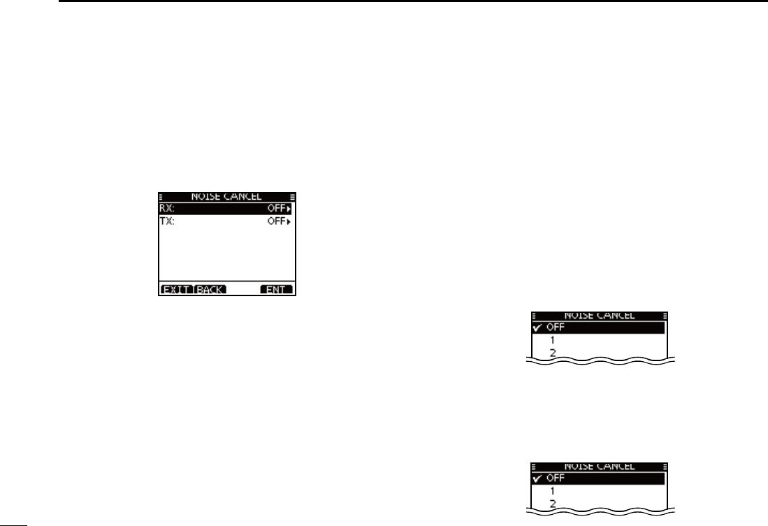
99
11 MENU SCREEN OPERATION
D Noise Cancel
Set the Noise Cancel function for both receive and transmit.
q
When the “NOISE CANCEL” screen is displayed, rotate Dial
or push [∫]/[√] to select “RX” or “TX,” and then push [ENT].
Rotate Dial or push [ w∫]/[√] to select the option, and then
push [ENT] to set it.
sh” is displayed next to the selected option.
Push [EXIT] to exit the Menu screen. e
s0USH;#,%!2=OR;"!#+=TORETURNTOTHEPREVIOUSSCREEN
s28
Turn the receive Noise Cancel function ON or OFF.
OFF : Turns OFF the function. (Default)
1 : The Noise Cancel function reduces random noise com-
ponents in the received signal to approximately one
half.
2 : The Noise Cancel function reduces random noise com-
ponents in the received signal to approximately one
third.
3 : The Noise Cancel function reduces random noise com-
ponents in the received signal to approximately one
tenth.
s48
Turn the transmit Noise Cancel function ON or OFF.
OFF : Turns OFF the function. (Default)
ON : The Noise Cancel function reduces random noise com-
ponents in the transmitted signal to one third.

100
11
MENU SCREEN OPERATION
1
2
3
4
5
6
7
8
9
10
11
12
13
14
15
16
D Voice Record
This item can be selected as OFF or AUTO (Last 120 sec).
(p. 78)
(Default: AUTO)
D FAV on MIC
Turn ON to Select only favorite channels (P.18) and turn OFF
to select all channels with the microphone.
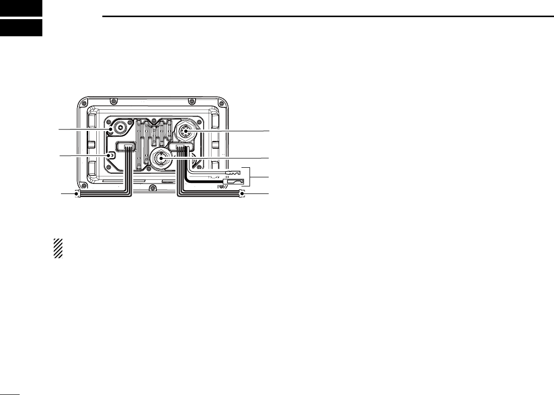
101
CONNECTIONS AND MAINTENANCE
12
Connections N
u
r
w
q
e
t
y
q ANTENNA CONNECTOR
Connects to a marine VHF antenna cable’s PL-259 con-
nector.
#!54)/. Transmitting without an antenna may dam-
age the transceiver.
w GROUND TERMINAL
Connects to a vessel ground to prevent electrical shocks
and interference from other equipment occurring. Use a
PH M3 × 6 screw (not supplied).
e NMEA 0183 IN/OUT LEADS
"ROWN4ALKER"$ATA,
Connects to an NMEA In Negative line of a PC or
NMEA0183 ver. 3.01 sentence format DSC, DSE compat-
ible navigation equipment, to receive position data from
other ships.
7HITE4ALKER!$ATA(
Connects to an NMEA In Positive line of a PC or NMEA0183
ver. 3.01 sentence format DSC, DSE compatible naviga-
tion equipment, to receive position data from other ships.
'REEN,ISTENER"$ATA,
Connects to an NMEA Out Negative line of a GPS receiver
for position data.
s!.-%!VEROR2-#''!'.3',,AND64'
sentence format compatible GPS receiver is required. Ask your
dealer about suitable GPS receivers.
9ELLOW,ISTENER!$ATA(
Connects to an NMEA Out Positive line of a GPS receiver
for position data.
s!.-%!VEROR2-#''!'.3',,AND64'
sentence format compatible GPS receiver is required. Ask your
dealer about suitable GPS receivers.
r AF OUT LEADS
"LUE%XTERNAL3PEAKER
"LACK%XTERNAL3PEAKERn
Connects to an external speaker.
/RANGE0UBLIC!DDRESS3PEAKER
'RAY(AILERn
Connects to a Hailer.
s(AILEROUTPUTPOWER-ORETHAN7ATDISTORTIONWITHA˘
load
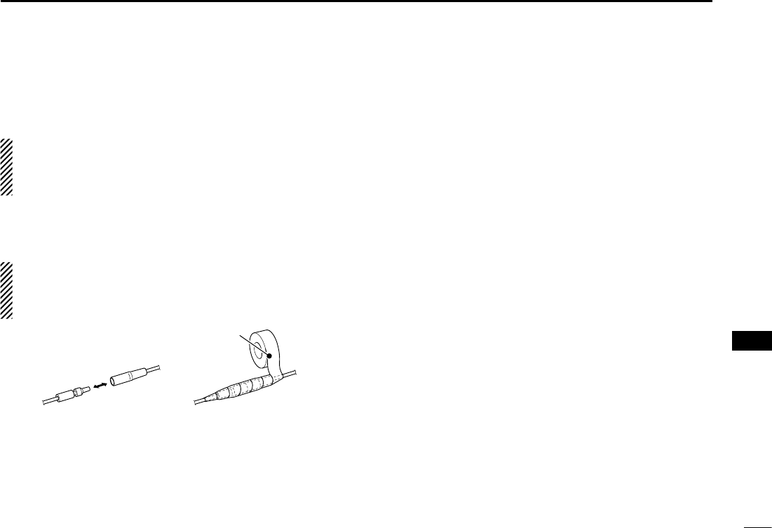
102
12
CONNECTIONS AND MAINTENANCE
./4%FOR.-%!)N/UTAND!&/UTLEADS
The connectors are attached to keep the leads together.
Before connecting to a piece of equipment, you should cut
the leads to remove the connector.
t DC POWER CONNECTOR
Connects to a 13.8 V DC power source.
#!54)/. After connecting the DC power cable, NMEA
leads, external speaker leads and Hailer leads, cover the
connector and leads with an adhesive tape, as shown be-
low, to prevent water seeping into the connection.
Rubber vulcanizing
tape
y NMEA 2000 CONNECTOR
Connects to the NMEA 2000 network.
u COMMAND MICROPHONE JACK
Connects to the optional Command microphone. (p. 106)
D Connect to the MA-500TR
Connect the transceiver to the high-density D-Sub 15-pin
connector of the MA-500TR using the OPC-2014* cable. Af-
ter connecting, an Individual DSC call can be made to the
AIS target using the transponder without entering the target’s
MMSI code.
* The OPC-2014 is supplied with the MA-500TR
s,ISTENER!$ATA(LEAD9ELLOW
Connects to lead 3 of the OPC-2014.
s,ISTENER"$ATA,LEAD'REEN
Connects to lead 2 of the OPC-2014.
s4ALKER!$ATA(LEAD7HITE
Connects to lead 5 of the OPC-2014.
s4ALKER"$ATA,LEAD"ROWN
Connects to lead 4 of the OPC-2014.
1
2
3
4
5
6
7
8
9
10
11
12
13
14
15
16
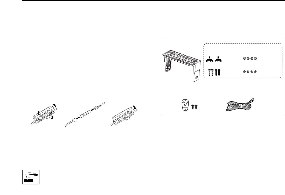
103
12 CONNECTIONS AND MAINTENANCE
Antenna N
A key element in the performance of any communication sys-
tem is the antenna. Ask your dealer about antennas and the
best place to mount them.
Fuse replacement N
One fuse is installed in the supplied DC power cable. If the
fuse blows or the transceiver stops functioning, track down
the source of the problem, repair it, and replace the damaged
fuse with a new one of the proper rating.
Fuse rating: 10 A
Cleaning N
If the transceiver becomes dusty or dirty, wipe it clean with a
soft, dry cloth.
DO NOT use harsh solvents such as benzine or
alcohol, as they will damage transceiver surfaces.
Supplied accessories N
Mounting bracket For mounting bracket
DC power cable
(OPC-891A)
Microphone hanger
and screws (3×16 mm)
Knob bolts
Screws (5×20 mm)
Flat washers (M5)
Spring washers (M5)
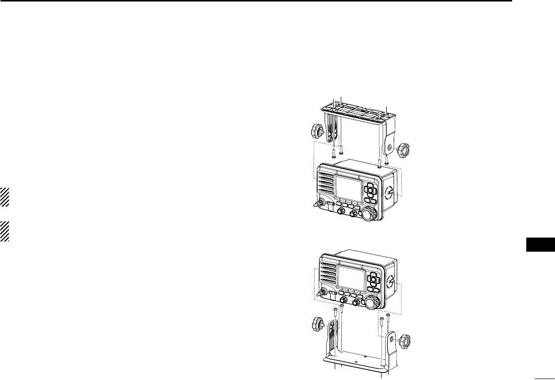
104
12
CONNECTIONS AND MAINTENANCE
Mounting the transceiver N
Using the supplied mounting bracket D
The universal mounting bracket supplied with your transceiv-
er allows overhead or dashboard mounting.
Mount the bracket securely to a surface which is more than q
10 mm thick and can support more than 5 kg using the 2
supplied screws (5 × 20 mm).
w Attach the transceiver to the bracket so that the face of the
transceiver is at 90° to your line of sight when operating it.
KEEP the transceiver and microphone at least 1 meter
away from the vessel’s magnetic navigation compass.
./4% Check the installation angle; the function display
may not be easy-to-read at some angles.
ARD
1
2
3
4
5
6
7
8
9
10
11
12
13
14
15
16
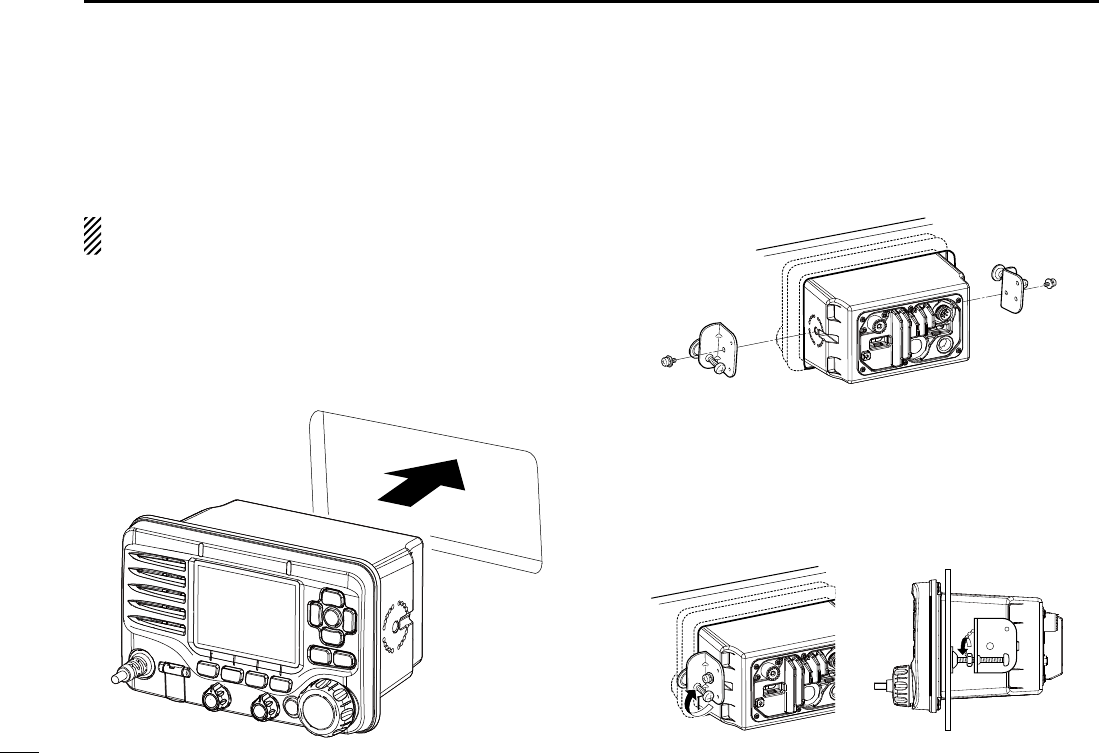
105
12 CONNECTIONS AND MAINTENANCE
MB-132 installation N
An optional MB-132 FLUSH MOUNT is available for mounting the
transceiver to a flat surface, such as an instrument panel.
KEEP the transceiver and microphone at least 1 meter
away from your vessel’s magnetic navigation compass.
Using the template on page 112, carefully cut a hole into q
the instrument panel, or wherever you plan to mount the
transceiver.
Slide the transceiver through the hole, as shown below. w
Attach the clamps on either side of the transceiver with 2 e
M5 × 8 mm supplied bolts.
s-AKESURETHATTHECLAMPSALIGNPARALLELTOTHETRANSCEIVERBODY
Tighten the end bolts on the clamps (clockwise) so that the r
clamps press firmly against the inside of the instrument
control panel.
Tighten the locking nuts (counterclockwise) so that the trans- t
ceiver is securely mounted in position, as shown below.
Connect the antenna and power cable, then return the in- y
strument control panel to its original place.
r
t
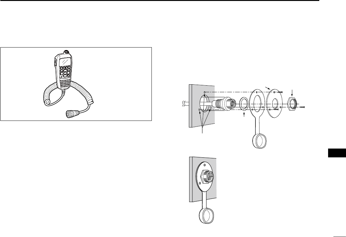
106
12
CONNECTIONS AND MAINTENANCE
1
2
3
4
5
6
7
8
9
10
11
12
13
14
15
16
Microphone installation N
The optional HM-195 should be connected to the transceiver
using the supplied OPC-1540 connection cable.
The cable is used to operate from a longer distance. The
cable connector can also be installed as a built-in plug on a
cabinet or wall.
To operate from even longer distances, the optional 6 meter
long OPC-1541 extension cable can be used between the
transceiver and the OPC-1540. Up to two OPC-1541 can be
added.
Installation D
Insert the OPC-1540 cable connector into the command q
microphone jack, and tighten the nut.
To use the cable connector as a wall socket, install it as w
described to the right.
Using the mounting base as a template, carefully mark the e
holes where the cable and three screws will be fastened.
Drill holes at these marks. r
Install the mounting base using the supplied screws, as t
shown below.
Gasket
Cap
Mounting base Nut
Screw holes
(approx. 2 (d) mm; 3⁄32˝)
The completed installation should look like this. y
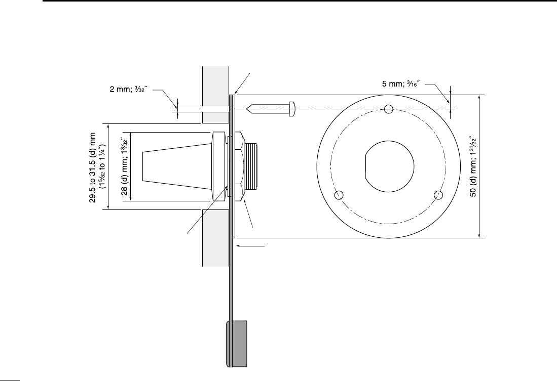
107
12 CONNECTIONS AND MAINTENANCE
Gasket
Mounting base
Cap
Nut

108
13
SPECIFICATIONS AND OPTIONS
1
2
3
4
5
6
7
8
9
10
11
12
13
14
15
16
Specifications N
General D
s&REQUENCYCOVERAGE
: Tx 156.0–1 MHz
Rx 156.000–163.425 MHz
s-ODE
FM (16K0G3E),
DSC (16K0G2B)
s#HANNELSPACING K(Z
s/PERATINGTEMPRANGE
–20°C to +60°C; –4ºF to +140ºF
s#URRENTDRAINAT6 48HIGH !MAXIMUM
Max. audio 5.0 A maximum
s0OWERSUPPLYREQUIREMENT 6 DC nominal
(negative ground)
s&REQUENCYSTABILITY ÒK(Zn#TO#
s!NTENNAIMPEDANCE ˘ nominal
s$IMENSIONSAPPROXIMATELY 7× 114(H) × 130(D) mm
(Projections not included) ;
7.1(W) × 4.0(H) × 5.0(D) inches
s7EIGHTAPPROXIMATELY 8KG8LB
Transmitter D
s/UTPUTPOWER 77
s-ODULATIONSYSTEM 6ARIABLEREACTANCEFREQUENCY
modulation
s-AXFREQUENCYDEVIATION ÒK(Z
s3PURIOUSEMISSIONS ,ESSTHANnD"CHIGH
Less than –56 dBc (low)
Receiver D
s2ECEIVESYSTEM $OUBLECONVERSION
superheterodyne
s3ENSITIVITYD"3).!$ nD"§TYPICAL
s3QUELCHSENSITIVITY ,ESSTHANnD"§
s)NTERMODULATIONREJECTIONRATIO -ORETHAND"
s
Spurious response rejection ratio
: More than 70 dB
s!DJACENTCHANNELSELECTIVITY -ORETHAND"
s!UDIOOUTPUTPOWER -ORETHAN7ATDISTOR-
tion with a 4 ˘ load
All stated specifications are subject to change without notice or obligation.
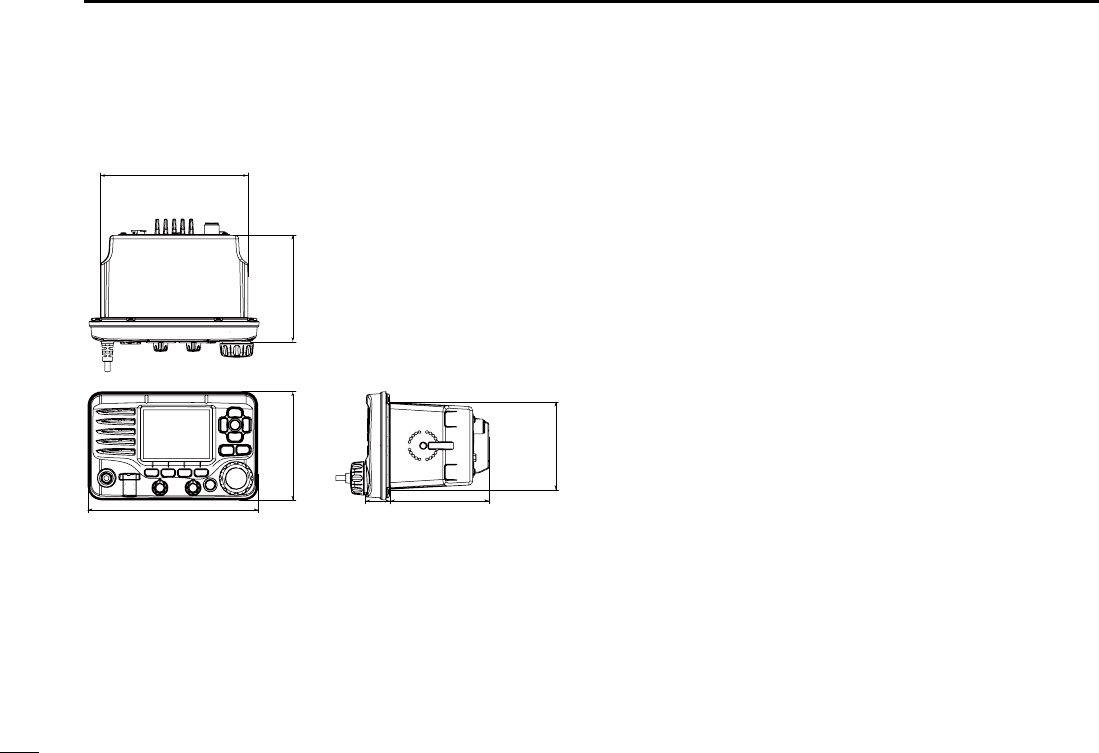
109
13 SPECIFICATIONS AND OPTIONS
D Dimensions
114 (4.0) 110 (4.33)
157 (6.2)
25(1.0) 105.0 (4.0)
93 (3.7)
Unit: mm (inch)
179 (7.1)
Options N
sMB-132 FLUSH MOUNT KIT
To mount the transceiver to a panel.
sHM-195 COMMANDMICIV™
External microphone-type controller. Provides optional in-
tercom operation. 6 m (20 ft) microphone cable and mount-
ing base included. Black and white colors are available.
sHM-205B/HM-205RB SPEAKER MICROPHONE
Equipped with [Y]/[Z] (channel up/down,) [HI/LO] and [PTT]
keys, a speaker and microphone.
sOPC-1541 MICROPHONE EXTENSION CABLE
6 m (20 feet) microphone extension cable for optional HM-
195 COMMANDMICIV™. Up to two OPC-1541 can be con-
nected. Usable length is 18 m (60 ft) maximum.
sMA-500TR CLASS B AIS TRANSPONDER
To transmit individual DSC calls to a selected AIS targets.
Approved Icom optional equipment is designed for optimal perfor-
mance when used with an Icom transceiver.
Icom is not responsible for the destruction or damage to an Icom
transceiver in the event the Icom transceiver is used with equipment
that is not manufactured or approved by Icom.

110
14
CHANNEL LIST
1
2
3
4
5
6
7
8
9
10
11
12
13
14
15
16
NOTE: Simplex channels, 3, 21, 23, 61, 64, 81, 82 and 83 CANNOT
be lawfully used by the general public in U.S.A. waters.
*1 Low power only. *2 Momentary high power. *3 DSC operation only.
Channel number Frequency (MHz)
03 156.150 160.75003
03A 156.150 156.150
156.200 160.80004
02 156.100 160.70002
04A 156.200 156.200
156.250 160.85005
05A 05A 156.250 156.250
06 06 156.300 156.30006
156.350 160.95007
07A 07A 156.350 156.350
08 08 156.400 156.40008
09 09 156.450 156.45009
10 10 156.500 156.50010
11 11 156.550 156.55011
12 12 156.600 156.60012
13*213*1
156.650 156.650
13
14 14
156.700 156.700
14
15*215*1
156.750 156.750
15*1
16 16
156.800 156.800
16
17*117*1
156.850 156.850
17
156.900 161.500
18
18A 18A
156.900 156.900
156.950 161.550
19
19A 19A 156.950 156.950
20 20*1157.000 161.60020
20A 157.000 157.000
01A 156.050 156.050
USA
01
156.050 160.65001
CAN
Transmit Receive
INT
Channel number Frequency (MHz)
157.100 161.70022
22A 22A 157.100 157.100
23 157.150 161.75023
21b Rx only 161.650
23A 157.150 157.150
24 24 157.200 161.80024
25 25 157.250 161.85025
25b Rx only 161.850
26 26 157.300 161.90026
27 27 157.350 161.95027
28 28 157.400 162.00028
28b Rx only 162.000
60 156.025 160.62560
156.075 160.67561
61A 61A 156.075 156.075
156.125 160.72562
62A 156.125 156.125
156.175 160.77563
63A 156.175 156.175
64 156.225 160.82564
64A 64A 156.225 156.225
156.275 160.87565
65A 65A 156.275 156.27565A
156.325 160.92566
66A 66A*1156.325 156.32566A
67*267 156.375 156.37567
21A 21A 157.050 157.050
USA
21 157.050 161.65021
CAN
Transmit Receive
INT
Channel number Frequency (MHz)
71 71 156.575 156.57571
72 72 156.625 156.62572
73 73 156.675 156.67573
70*370*3156.525 156.52570*3
74 74 156.725 156.72574
75*175*1156.775 156.77575*1
76*176*1156.825 156.82576*1
77*177*1156.875 156.87577
156.925 161.52578
78A 78A 156.925 156.925
156.975 161.57579
79A 79A 156.975 156.975
157.025 161.62580
80A 80A 157.025 157.025
157.075 161.67581
81A 81A 157.075 157.075
157.125 161.72582
82A 82A 157.125 157.125
83 157.175 161.77583
83A 83A 157.175 157.175
83b Rx only 161.775
84 84 157.225 161.82584
84A 157.225 157.225
85 85 157.275 161.87585
85A 157.275 157.275
86 86 157.325 161.92586
69 69 156.475 156.47569
68
USA
68 156.425 156.42568
CAN
Transmit Receive
INT
Channel number Frequency (MHz)
88 88 157.425 162.02588
88A 157.425 157.425
87A 157.375 157.375
87 87 157.375 161.97587
86A
USA
157.325 157.325
CAN
Transmit Receive
INT
Frequency (MHz)
RX only 162.425
RX only 162.450
RX only 162.500
RX only 162.475
RX only 162.525
RX only 161.650
RX only 161.775
RX only 163.275
RX only 162.400
RX only 162.550
Transmit Receive
WX channel
4
5
6
3
7
8
9
10
2
1

111
TROUBLESHOOTING
15
PROBLEM POSSIBLE CAUSE SOLUTION REF.
The transceiver does
not turn ON.
s"ADCONNECTIONTOTHEPOWERSUPPLY s#HECKTHECONNECTIONTOTHETRANSCEIVERAND
power supply.
p. 101
Little or no sound comes
from the speaker.
s3QUELCHLEVELISSETTOOHIGH
s6OLUMELEVELISSETTOOLOW
s3PEAKERHASBEENEXPOSEDTOWATER
s3ETTHESQUELCHTOTHETHRESHOLDPOINT
s3ETTHEVOLUMETOASUITABLELEVEL
s2EMOVETHEWATERWITHTHE!QUA1UAKEFUNC-
tion.
p. 3
p. 4
p. 15
Transmitting is impossi-
ble, or high power can-
not be selected
.
s3OME CHANNELS ARE PROGRAMMED FOR LOW
power or receive only by regulations.
s4HEOUTPUTPOWERISSETTOLOW
s#HANGECHANNELS
s0USH;(),/=TOSELECTHIGHPOWER
pp. 9,
10, 11
p. 11
Scan does not start. s&AVORITECHANNELSARENOTPROGRAMMED s3ET THE DESIRED CHANNELS AS &AVORITECHAN-
nels.
p. 18
No beep sounds. s"EEPTONESARETURNED/&& s4URNTHEBEEPTONES/.INTHE#/.&)'52!-
TION menu.
p. 93
Distress calls cannot be
transmitted.
s--3) $3# SELF )$ CODE IS NOT PRO-
grammed.
s0ROGRAMTHE--3)$3#SELF)$CODE p. 8
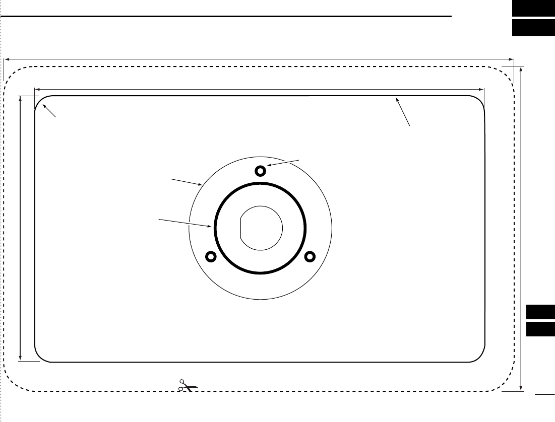
Cut here
Unit: mm (inch)
R8 (Max.)
29.5 to 31.5 (d)
(1 5⁄32 to 1 1⁄4)
178.9 (7.04)
113.9 (3 7⁄32)
157.0(6.18)
93.4 (2 15⁄32)
MB-132
HM-195
2 (3⁄32)
112
16
TEMPLATE
1
2
3
4
5
6
7
8
9
10
11
12
13
14
15
16

MEMO

1-1-32 Kamiminami, Hirano-ku, Osaka 547-0003, Japan
A-7129D-1EX
Printed in Japan
© 2014 Icom Inc.
Printed on recycled paper with soy ink.