ICOM orporated 359800 Dual Band Transceiver User Manual
ICOM Incorporated Dual Band Transceiver
UserManual.wiki
>
ICOM orporated
>
359800 User Manual
User Manual
Navigation menu
Upload a User Manual
Namespaces
Wiki Guide
HTML
PDF
Info
Views
User Manual
Discussion / Help
Navigation
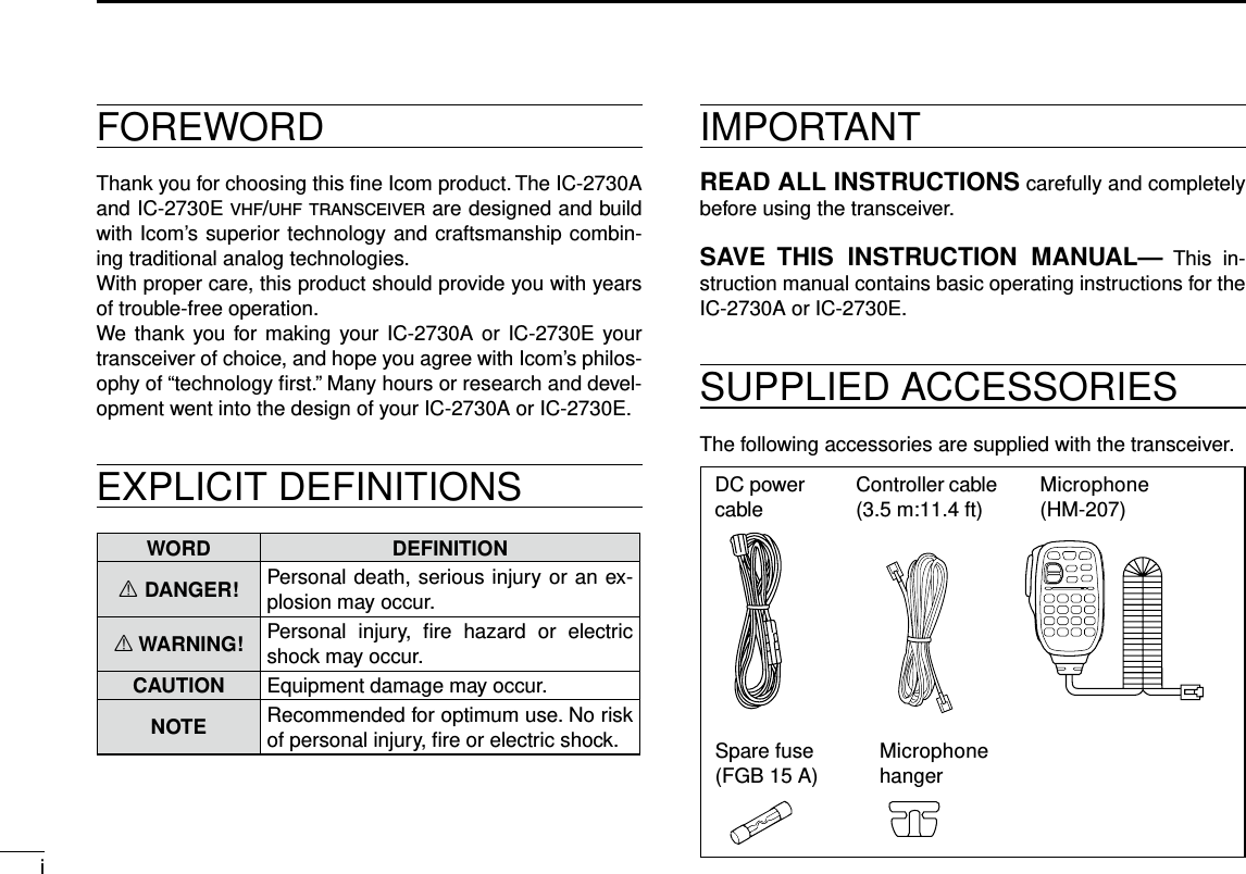
 Hold down for 1 second to turn power ON or OFF. ➥(p. ??) Push to mute the audio. ➥(p. ??)wMAIN•BANDKEY[MAINBAND] Push to select the MAIN band. (p. ??) In the VFO mode Hold down for 1 second to enter the Operating band select mode. (p. ??) In the Memory mode Hold down for 1 second to enter the Memory bank select mode. (p. ??)eVFO/MHzTUNING•SCANKEY[V/MHzSCAN] Push to select the VFO mode. ➥ In the VFO mode, push to select 1 MHz ➥ tuning. (p. ??) Hold down for 1 second to enter the Scan type select ➥mode. (p. ??)rMEMORY•CALLKEY[MRCALL] Push to select the Memory mode. ➥(p. ??) In the VFO mode, push to select the Weather channel ➥mode.* (p. ??) *Weather channels available for USA versions only. Hold down for 1 second to select the Call channel ➥mode. (p. ??)t VOLUME CONTROL (p. ??)y TUNING DIAL [DIAL] In the VFO mode Rotate to select the operating frequency. (p. ??) In the Memory mode Rotate to select Memory channel. (p. ??) While scanning Rotate to change the scanning direction. (p. ??) In the MENU mode Rotate to select a desired option or value. (p. ??)u SQUELCH CONTROL (p. ??) Rotate to adjust the squelch level.iMONITOR•DUPLEXKEY[DUPMONI] Push to turn the Monitor function ON and OFF. ➥(p. ??) Push and hold for 1 second to select DUP–, DUP+, or ➥simplex operation. (p. ??)Display (p. ?)Microphone connector (p. ?)For your reference:The key-touch beep tones on the left band are different than the tones on the right band. The different tones will let you know which band you are operating.](https://usermanual.wiki/ICOM-orporated/359800/User-Guide-2474719-Page-7.png)
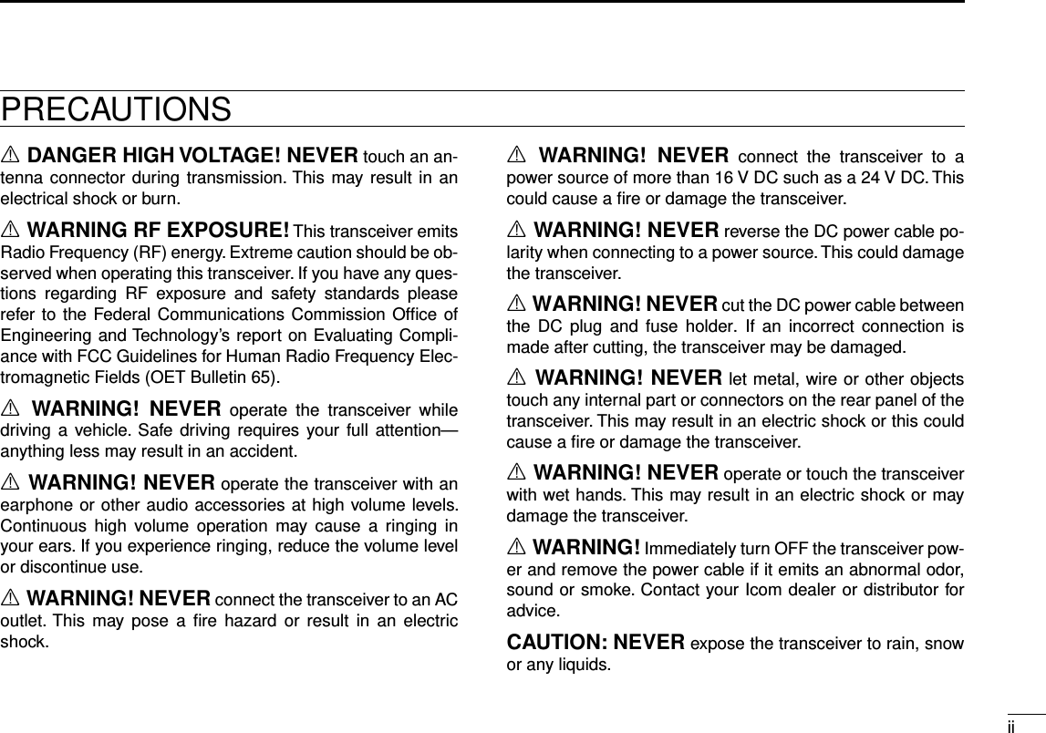
![21PANEL DESCRIPTIONNew2001 New2001New2001Controller — Display (Continued) ■oOUTPUTPOWER•DTMFKEY[LOWDTMF] Push to ➥select the transmit output power level. (p. ??) Hold down for 1 second to turn DTMF memory encoder ➥ON and OFF. (p. ??)!0 MEMORY WRITE KEY [MW] In the VFO modePush to display the Memory write screen. ➥(p. ??) Hold down for 1 second to store the operating frequen- ➥cy into a blank Memory channel. In the Memory mode Push to display the Memory channel entry screen. ➥(p. ??) Hold down for 1 second to display the Memory channel ➥setting screen. (p. ??)!1 MENU LOCK KEY [MENU ]Push to enter the MENU mode. ➥ Hold down for 1 second to turn the Lock function ON ➥or OFF.Controller — Display ■q MAIN ICON Displayed on the MAIN band. (p. ??) •YoucantransmitonlyontheMAINband. •TheMENUmodesettingsarefortheMAINband.w TX ICON (p. ??)e DUPLEX ICON (p. ??) Displayed while in the duplex mode.r TONE ICONS (p. ??)t Bluetooth® ICON (p. ??) Displayed when you make a Bluetooth® connection be-tween your transceiver* and a Bluetooth® device. *Requires an optional UT-133 Bluetooth® u n i t installed.y KEY LOCK ICON (p. ??) Displayed when a key or controller is locked.!0!1!8 !7!9!2!3!4!5!6q w e r t yuioo !0 !1](https://usermanual.wiki/ICOM-orporated/359800/User-Guide-2474719-Page-8.png)
![New200131PANEL DESCRIPTIONNew20011PANEL DESCRIPTIONu FREQUENCY READOUT (p. ??)i MEMORY CHANNEL NUMBER (p. ??) Displays the selected Memory channel number, Memory Bank number, Call channel number, or Menu item name.o PRIORITY ICON (p. ??) Displayed when the Priority watch is turned ON.!0 SKIP ICON (p. ??) Appears when the displayed Memory channel is specified as a skip channel.!1 MODE ICON (p. ??)!2 POWER ICON (p. ??)!3 VOX ICON (p. ??) Displayed when the transceiver is connected to the op-tional VS-3 Bluetooth® h e a d s e t , and the VOX function is ON.!4 MEMORY MODE ICON (p. ??)!5 S/RF METER Displays the relative signal strength of the receive sig- ➥nal. (p. ??) Displays the output power level of the transmit signal. ➥(p. ??)!6 BUSY ICON Displayed while a signal is being received or the squelch ➥is open. (p. ??)Blinks while the Monitor function is activated. ➥(p. ??)!7 CLEAR KEY [CLR] In the MENU mode Push [MENU ] to return to the previous screen. (p. ??) While entering text Push [MENU ➥] to delete the selected character, symbol or number. (p. ??) Hold down [MENU ➥] for 1 second to delete the se-lected character, symbol or number, and all characters that are located to the right of the cursor. (p. ??)!8 ENTER KEY [ï] Push [MW] to go to the next tree level or to set the option or value in the MENU mode. (p. ??)!9 LEFT/RIGHT KEYS [Ω]/[≈] In the MENU mode [Ω]: Push [MONI DUP] to go back the previous tree level. (p. ??) [≈]: Push [LOW DTMF] to go to the next tree level. (p. ??)](https://usermanual.wiki/ICOM-orporated/359800/User-Guide-2474719-Page-9.png)
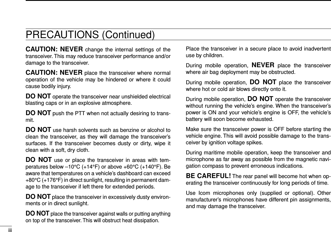
![41PANEL DESCRIPTIONNew2001 New2001New2001Main unit ■q CONTROLLER CONNECTOR [CONTROLLER] (p. ??) Connects to the Controller using the supplied control cable.w MICROPHONE CONNECTOR [MIC] Plug in the supplied HM-207 microphone or the optional HM-154 microphone.e ANTENNA CONNECTOR (p. ??) Connect a 50 ø impedance antenna with a PL-259 con-nector. The transceiver has a built-in duplexer, so you can use a 144 and 430 MHz dual-band antenna without needing an external duplexer. r COOLING FAN The cooling fan for heat dissipation. You can select the Fan control option in the Menu screen, to automatically start rotating when you begin transmitting, or continuously rotate from power ON. (p. ??)t DC POWER SOCKET [DC 13.8V] Connect a 13.8 V DC power source through the supplied DC power cable.y EXTERNAL SPEAKER JACK 2 [SP2]u EXTERNAL SPEAKER JACK 1 [SP1] Connect an 8 ohm external speaker. •Seethefollowinglistforthespeakerconnectionandaudioout-put details.Ex. speaker connection statusAudio outputExternal speaker Internal speakerSP-1 SP-2SP-1 and SP-2 Left band Right band –SP-1 only Both bands – –SP-2 only –Right band Left bandMicrophone connector information D12345678Front panel view1 8 V +8 V DC outputMaximum 10 mA2 MIC U/D Frequency Up/DownUP: GroundDN: Ground through 470 ˘3 M8V SW HM-207 connectionGrounds when the HM-207 is connected.4 PTT PTT inputGround for transmission5 MIC E Microphone ground6 MIC Microphone input7 GND PTT ground8 DATA INInputs HM-207 data when the HM-207 is connected.q w e rtyuFront panel Rear panel](https://usermanual.wiki/ICOM-orporated/359800/User-Guide-2474719-Page-10.png)
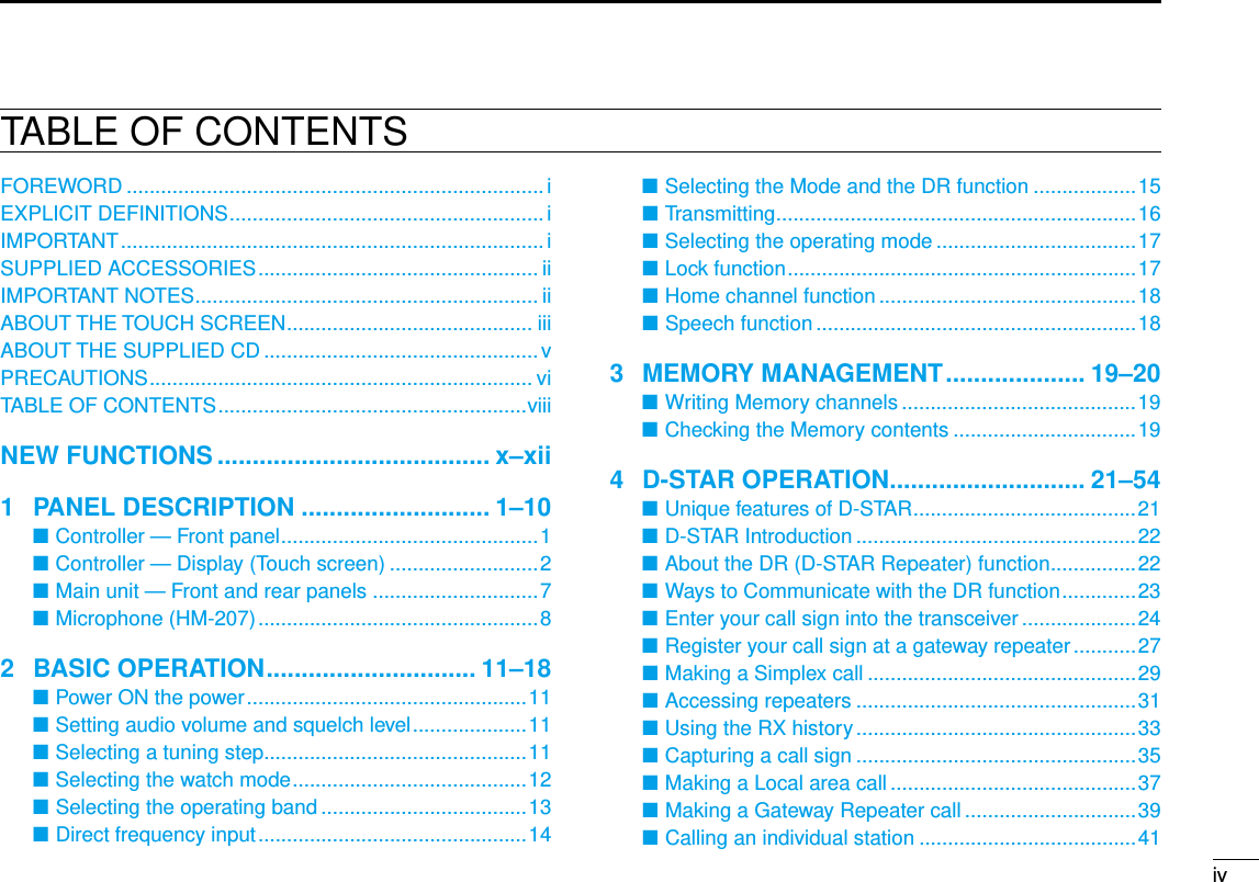
![New200151PANEL DESCRIPTIONNew20011PANEL DESCRIPTIONWith the HM-207, you can input numbers for frequency or Memory channel settings, and adjust the audio volume and squelch level.qwe!0tyiuorMic elementq LED 1 Lights red while transmitting by pushing [PTT].w [∫]/[√] (UP/DOWN) KEYS Push to change the operating frequency or Memory ➥channel. Hold down to continuously change the frequency or ➥Memory channel.e [PTT] SWITCH Hold down to transmit, release to receive.r [VFO/MR ] KEY Push to toggle between the VFO and Memory modes. ➥ Hold down for 1 second to turn the Lock function ON ➥or OFF. (p. ??)t [HOME CALL] KEYPush to select the Home channel. ➥ Hold down for 1 second to turn the Call channel mode ➥ON or OFF.y [MAIN DUAL] KEY Push to toggle between the MAIN and SUB bands.u [F-1] KEY Push to activate the preset function of the [F-1] key. (Default: During RX/Standby: [BAND/BANK] During TX: [T-CALL]) [F-2] KEY Push to activate the preset function of the [F-2] key. (Default: During RX/Standby: [Monitor] During TX: [---])You can assign a desired function in the MENU mode. (p. ??, ??)i [CLR] KEY In the Menu screen or Quick Menu window, push to return to the standby screen.o [ENT] KEY After entering a VFO frequency or memory channel num-ber, push to set.!0 LED 2 Lights green when transceiver’s power is ON.About the HM-207 microphone ■](https://usermanual.wiki/ICOM-orporated/359800/User-Guide-2474719-Page-11.png)
![61PANEL DESCRIPTIONNew2001 New2001New2001!1 [VOL∫ A] KEYPush to increase the audio output level. ➥When entering a DTMF code, push to input ‘A.’ ➥!2 [VOL√ B] KEYPush to decrease the audio output level. ➥When entering a DTMF code, push to input ‘B.’ ➥!3 [SQL∫ C] KEYPush to increase the squelch level. ➥When entering a DTMF code, push to input ‘C.’ ➥!4 [SQL√ D] KEYPush to decrease the squelch level. ➥When entering a DTMF code, push to input ‘D.’ ➥!5 [# CE] KEY In the frequency entry screen, push to delete a num- ➥ber.When entering a DTMF code, push to input ‘#.’ ➥!6 [M .] KEY In the frequency entry screen, push to input a ‘.’ (deci- ➥mal point).When entering a DTMF code, push to input ‘ ➥M.’!7 [0] to [9] KEYS In the frequency entry window or while entering a DTMF code, push to input ‘0’ through ‘9.’Setting frequency and Memory channel D[Example for setting the frequency]First, push [VFO/MR ] to select the VFO mode.To enter 435.680 MHz:Push [4], [3], [5], [6], [8], [0], then [ENT]. ➥To change 435.680 MHz to 435.540 MHz:Push[•],[5],[4],[0],then[ENT]. ➥To enter 433.000 MHz:Push [4], [3], [3], then [ENT]. ➥[Example for setting the Memory channel]To select the Memory channel ‘5’:First, push [VFO/MR ] to select the Memory mode, and then push [5] then [ENT].[Example for setting the Call channel]To select the ‘0’ or ‘1’ Call channel:First, hold down [HOME CALL] for 1 second to select the Call channel mode, and then push [∫] or [√].Microphone (HM-207) (Continued) ■!7!6!1!2!3!4!5](https://usermanual.wiki/ICOM-orporated/359800/User-Guide-2474719-Page-12.png)
![New200171PANEL DESCRIPTIONNew20011PANEL DESCRIPTIONThe following functions can be set to [F-1] and [F-2] to use during receive or in stand-by, or during TX.During RX/Standby: Function Description--- No functionMonitor([F2] key: Default)Push to open or close the squelch.MR (000 CH) In the Memory mode, push to select Memo-ry channel 000.MR (001 CH) In the Memory mode, push to select Memo-ry channel 001.BAND/BANK([F1] key: Default)Push to select an operating band.In the VFO mode, push to change the oper-ating band, and in the Memory Bank mode, push to select Bank A to J, or OFF.•Onlytheprogrammedbankappears.SCAN Push to start a scan.While scanning, push to stop the scan.Temporary SkipPush to set the frequency to be skipped dur-ing scanning.The selected frequencies are temporarily skipped for faster scanning.MODE Push to change the operating mode.LOW Push to change the transmit power level.DUP Push to turn the Duplex mode ON or OFF, and the shift direction to DUP+ or DUP–.PRIOPush to turn the Priority watch ON or OFF.TONE/DSQL Push to toggle between tone types.Function DescriptionMWIn the VFO mode, hold down for 1 second to save the frequency displayed in the MAIN band into a Memory channel.•Thefrequencyisautomaticallysavedinablankchannel.MUTE Push to turn the Mute function ON or OFF.DTMF DIRECT TX Push to display the DTMF code direct entry mode screen.T-CALL Push to transmit a 1750 Hz tone.During TX: Function Description---([F2] key: Default)No functionLOW Push to change the transmit power level.Voice TXPush to transmit the voice audio recorded on the SD card once.Hold down for 1 second to repeatedly trans-mit the voice audio.•Tomakearepeattransmission,[PTT]mustbereleased.T-CALL([F1] key: Default)Push to transmit a 1750 Hz tone.](https://usermanual.wiki/ICOM-orporated/359800/User-Guide-2474719-Page-13.png)
![1New2001New2001MENU MODE2New2001The Menu mode is used to program infrequently changed val-ues or function settings.The Menu mode items are activated on the Main band.In addition to this page, see pages ?? through ?? for details of each item’s options and their default value.For your reference: The Menu system is constructed in a tree structure. You may go to the next tree level, or go back a level, depending on the selected item.Selecting the Menu item ■Example: Set the tuning step Push [MAIN BAND] qS of the band that the tuning step is set. •SelectstheMainband.Push [MENU w]C. •EnterstheMenumode. e Rotate [DIAL]S to select the “MENU-TS” (Tuning step) item. To return to the default setting:Hold down [MR CALL] after step r operation.Push [ rï]D. •Goestothenexttreelevel. •Pushing[≈]D also goes to the next tree level.Rotate [DIAL] tS to select the desired value. Selectable values: 5 kHz, 6.25 kHz, 8.33 kHz*, 10 kHz, 12.5 kHz, 15 kHz, 20 kHz, 25 kHz, 30 kHz, 50 kHz or Auto*. *Appears only when the AIR band is selected.Push [ yï]D. •Setstheselectedvalue,andgoesbacktotheprevioustreelev-el. •Pushing[Ω]D also goes back to the previous tree level.Push [MAIN BAND] uS. •ExitstheMenumode. •Pushing[V/MHz SCAN]S or [MR CALL]S also exits the Menu mode.Side SideDisplayCenterThe C, S or D in the instructions indicate the part of the controller.C: CenterS: SideD: Display](https://usermanual.wiki/ICOM-orporated/359800/User-Guide-2474719-Page-14.png)
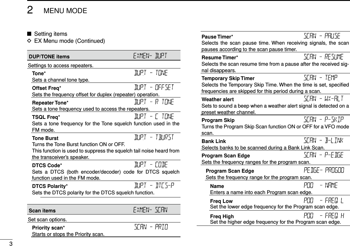
![New200122MENU MODENew20012MENU MODESetting items ■Menu mode DSee pages ?? to ?? for details of the Menu mode items.Tone Sets a channel tone type.Offset Freq Sets the frequency offset for duplex (repeater) operation.Repeater Tone Sets a tone frequency used to access the repeaters.TSQL Freq Sets a tone frequency for the Tone squelch function used in the FM mode.DTCS Code Sets a DTCS (both encoder/decoder) code for DTCS squelch func-tion used in the FM mode.DTCS Polarity Sets the DTCS polarity for the DTCS squelch function.Tuning step Sets the tuning step to change the frequency by rotating [DIAL] in the selected step.LCD Backlight Sets the backlight brightness level.Priority scan Starts or stops the Priority scan.Pause Timer Sets the scan pause time. When receiving signals, the scan pauses according to the scan pause timer.Resume Timer Sets the scan resume time from a pause after the received signal disappears.Weather alert Sets to sound a beep when a weather alert signal is detected on a preset weather channel.Operating mode Sets the operating mode.Home CH Sets the often-used frequency as the Home channel in the VFO mode or Memory mode.EX Menu mode Enters the EX Menu mode.EX Menu mode DSee the Icom website for details of the EX Menu mode items.Mode and Tuning step items Sets the operating mode and the tuning step.Operating mode* Sets the operating mode.Tuning step* Sets the tuning step to change the frequency in the selected step when rotating [DIAL].](https://usermanual.wiki/ICOM-orporated/359800/User-Guide-2474719-Page-15.png)
![New200142MENU MODENew20012MENU MODEProgram Link Sets the link function for the program scan edge channels.Program Scan Link channels Displays a maximum of 10 Program Scan Link channels.Link Displays the Program Scan channels that are scanned during the Program Link scan.Name Enters a name into each Program Scan channel.Add Adds the Program Scan channel that is scanned during the Program Link scan.Clear Deletes the Program Scan channel that is scanned during the Program Link scan.Function items Sets various function’s options.Squelch/ATT Select Sets to use the S-Meter Squelch or the Attenuator function for the [SQL] control.Squelch Delay Sets the squelch delay to short or long until the squelch opens.Fan Control Sets the cooling fan control condition.Dial Speed-UP Sets to automatically speeds up the tuning dial speed when rapidly rotating [DIAL].Auto Repeater* Turns the Auto Repeater function ON or OFF.Remote MIC Key Selects the key function for [F-1] or [F-2] on the supplied HM-207 remote-control microphone.During RX/Standby Selects the key function to be used while receiving or in the standby mode.During TX Selects the key function to be used while transmitting.Up/Down MIC Key Selects the key function for [UP] or [DN] on the optional HM-154 hand microphone.During RX/Standby Selects the key function to be used while receiving or in the standby mode.During TX Selects the key function to be used while transmitting.One-Touch PTT Turns the One-Touch PTT function ON or OFF.PTT Lock Turns the PTT Lock function ON or OFF.Busy Lockout Turns the Busy Lockout function ON or OFF.Time-Out Timer Selects the Time-Out Timer time options.Active Band Allows continuous frequency selection across all bands by rotat-ing [DIAL].](https://usermanual.wiki/ICOM-orporated/359800/User-Guide-2474719-Page-17.png)
![52MENU MODENew2001 New2001New2001Function items (Continued) MIC Gain Sets the microphone sensitivity to suit your preference.Auto Power OFF Sets to automatically turn OFF the transceiver after a preset time period of inactivity.CI-V CI-V Address Sets the transceiver’s unique CI-V hexadecimal address code.CI-V Baud Rate Sets the CI-V code transfer speed.CI-V Transceive Turns the CI-V Transceive function ON or OFF.IF Exchange Sets to exchange the Intermediate Frequency to prevent interfer-ence.Display items Sets the Display options.LCD Backlight* Sets the backlight brightness level.Auto Dimmer Sets the Auto dimmer function, and the dimmer level.Auto Dimmer Timer Sets the backlight lighting time period.LCD Contrast Sets the contrast level of the LCD.Opening Message Sets whether or not to display “ICOM” and power source voltage at power ON.Memory Name Sets to display either the operating frequency or the channel name for the Memory mode.AIR Band Display Sets the display type of the VHF AIR band frequency.Sound items Sets the Sound options.Beep Level Sets the beep output level.Key-Touch Beep Sets to sound a beep when you push a key.•Thebeeptonesaredifferentbetweenontheleftbandandtheright band.Home CH Beep Sets to sound a beep when you select the Home CH.Band Edge Beep Sets to sound a beep when you tune into or out of the AIR, VHF and UHF band’s frequency range by rotating [DIAL].Scan Stop Beep Sets to sound a beep when a scan stops by receiving a signal.Sub Band Mute Sets to mute the SUB band audio signal while receiving on the MAIN band.Setting items ■EX Menu mode D](https://usermanual.wiki/ICOM-orporated/359800/User-Guide-2474719-Page-18.png)
![New200162MENU MODENew20012MENU MODEHome CH items* Sets the often-used frequency as the Home channel in the VFO mode or Memory mode.Setting Sets a displayed frequency as a Home channel.Clear Cancels the current Home channel.This item does not appear when no Home channel is set.Bluetooth® items Sets the Bluetooth® options.Bluetooth® Turns the Bluetooth® function ON or OFF.Auto Connect Sets to automatically connect to the paired Bluetooth® device when its device is ON.Bluetooth® connection Displays the connected Bluetooth® device.Bluetooth® disconnection Disconnects from the connected Bluetooth® device without can-celling the pairing.Paring/Connect Searches for the Bluetooth® device to connect, or view the paired Bluetooth® devices in the list.Headset Set AF Output Selects the AF output option for when you use the Bluetooth® headset.VOX VOX Sets the VOX (Voice Operated Transmission) function for when you use the Bluetooth® headset.VOX Level Set the VOX gain level.Higher values make the VOX function more sensitive to your voice.VOX Delay Sets the VOX Delay time for the transmitter stays ON after you stop speaking before the VOX switches to receive.VOX Time-Out Timer Sets the VOX Time-Out Timer to prevent an accidental prolonged transmission.Icom Headset Sets to use the optional Icom Bluetooth® headset (VS-3).Power Save Sets the Power save function to prolong the headset battery.One-Touch PTT Sets the One-Touch PTT function to toggle between transmis-sion and reception by pushing [PTT].PTT Beep Sets to sound a beep when you push [PTT].Custom Key Beep Sets to sound a beep when you push the custom key ([PLAY]/[FWD]/[RWD]).Custom Key Sets the key function of the custom key ([PLAY]/[FWD]/[RWD]).Initialize Bluetooth Device Selects to reset the optional UT-133 Bluetooth® unit.](https://usermanual.wiki/ICOM-orporated/359800/User-Guide-2474719-Page-19.png)
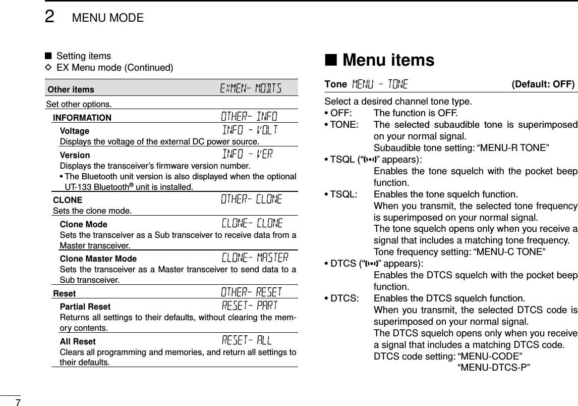
![New200182MENU MODENew20012MENU MODE•TSQL-R: Enablesthereversetonesquelchfunction. When you transmit, the selected CTCSS tone is not superimposed on your normal signal. The tone squelch opens only when you receive a signal that includes a non-matching subaudible tone.•DTCS-R: EnablesthereverseDTCSsquelchfunction. When you transmit, the selected DTCS code is not superimposed on your normal signal. The DTCS squelch opens only when you receive a signal that includes a non-matching DTCS code. DTCS code setting: “MENU-CODE” “MENU-DTCS-P”•DTCS(T):When you transmit, the selected DTCS code issuperimposed on your normal signal. When you receive, the function is OFF. DTCS code setting: “MENU-CODE” “MENU-DTCS-P”•TONE(T)/DTCS(R): When you transmit, the selected subaudible tone is superimposed on your normal signal. When you receive, the DTCS squelch opens only for a signal that includes a matching DTCS code. Subaudible tone setting: “MENU-R TONE” DTCS code setting: “MENU-CODE” “MENU-DTCS-P”•DTCS(T)/TSQL(R): When you transmit, the selected DTCS code is superimposed on your normal signal. The tone squelch opens only when you receive a signal that includes a matching tone frequency. DTCS code setting: “MENU-CODE” “MENU-DTCS-P” Tone frequency setting: “MENU-C TONE”•TONE(T)/TSQL(R): When you transmit, the selected subaudible tone is superimposed on your normal signal. The tone squelch opens only when you receive a signal that includes a matching tone frequency. Subaudible tone setting: “MENU-R TONE” Tone frequency setting: “MENU-C TONE”Offset frequency (Default: 0.600.00*)Set the frequency offset for duplex (repeater) operation to be-tween 0 and 59.99500 MHz.•Theduplexshiftdirection(DUP–/DUP+)issetintheduplexsetting screen that is displayed when you hold down [MONI DUP] for 1 second in the VFO mode. (p. ??)* The default value may differ, depending on the frequency band (selected as the Main band before entering the Menu mode) and the transceiver version.](https://usermanual.wiki/ICOM-orporated/359800/User-Guide-2474719-Page-21.png)

![New2001102MENU MODENew20012MENU MODETuning step (Default: 25.0)When you rotate [DIAL] in the VFO mode, the frequency changes in the selected tuning step.The selected tuning step is also used for a VFO mode scan.Tuning steps (kHz):5, 6.25, 8.33*, 10, 12.5, 15, 20, 25, 30, 50 and Auto**Appears only when the AIR band is selected.In the AIR band, you can select only “8.33k”, “25k” and “Auto.”LCD Backlight (Default: 4)Set the backlight brightness level to between 1 (Dark) and 4 (Bright).Priority scan (Default: OFF)Starts or stops the Priority scan.•OFF: StopsthePriorityscan.•ON: StartsthePriorityscan.•BELL: StartsthePriorityscan. When a signal is received on the priority channel, the “” icon is displayed on the screen.Pause Timer (Default: 10SEC)Select the Scan Pause time.•2SEC to 20SEC: When a signal is received, the scan paus-es for 2 to 20 seconds (set in 2 second steps).•HOLD: The scan pauses on a received signal until the signal disappears.Resume Timer (Default: 2SEC)Select the Scan Resume time.When a received signal disappears, the scan resumes ac-cording to this setting.•0SEC: The scan resumes immediately after thesignal disappears.•1SECto5SEC: Thescanresumes1to5secondsafterthesignal disappears.•HOLD: The scan remains paused for the“PauseTimer” setting, even if the signal disap-pears. NOTE: • Rotate [DIAL] to resume the scan. • The Resume Timer must be set shorter than the Pause Timer, otherwise this timer does not work properly.](https://usermanual.wiki/ICOM-orporated/359800/User-Guide-2474719-Page-23.png)
![112MENU MODENew2001 New2001New2001Weather alert (Default: OFF)(Appears only for the U.S.A. version.)Turn the Weather Alert function ON or OFF.A NOAA (National Oceanographic and Atmospheric Admin-istration) broadcast station transmits a weather alert tone be-fore any important weather information.This function detects the weather alert tone on weather chan-nels.•OFF:ThefunctionisOFF.•ON: Monitorstheselected weather channelevery 5 sec-onds.Operating mode (Default: FM)The transceiver has a total of five operating modes; FM, FM-N, AM and AM-N.Operating modes are determined by the modulation of the radio signals.•Inthe144and430MHzbands,selectFMorFM-N.•IntheAIRband(118.000MHzto136.99166MHz),selectAM or AM-N.While in the FM-N mode, the TX modulation is automati-cally set to narrow (approximately ±2.5 kHz)Menu items (Continued) ■Home CH , When you set the often-used frequency as the Home chan-nel in the transceiver’s VFO or Memory mode, that frequency is selected by pushing [HOME CALL] of the supplied micro-phone in each mode.•SET.FREQ:SettheselectedVFOfrequency astheHomechannel.•SETMR: SettheselectedMemorychannelfrequencyasthe Home channel.EX Menu mode Enters the EX Menu mode.See pages ?? to ?? for the items that you can set in the EX Menu mode.See the Icom website for details of the EX Menu mode items.](https://usermanual.wiki/ICOM-orporated/359800/User-Guide-2474719-Page-24.png)
![New200113BASIC OPERATIONNew20013BASIC OPERATIONSelecting the MAIN band ■ Push [MAIN BAND] ➥S on the desired frequency band to set it as the MAIN band. •“MAIN”appearsontheMAINband. •YoucantransmitononlytheMAINband.Selecting the Mode ■•Youcanselectoneithertheleftorrightband,regard-less of the MAIN band.VFO mode DThe VFO mode is used to set the operating frequency.Push [V/MHz SCAN] ➥S. •SelectstheVFOmode. •Rotate[DIAL]S to select an operating frequency.Memory mode DThe Memory mode is used to operate on Memory channels.Push [MR CALL] ➥S. •SelectstheMemorymode. •Rotate[DIAL]S to select a Memory channel.Call channel mode DThe Call channel mode is used to operate on the Call chan-nels.Hold down [MR CALL] ➥S for 1 second. •SelectstheCallchannelmode. •Rotating[DIAL]S selects a Call channel.Weather channel mode D (Selectable in only the U.S.A. version transceivers)The Weather channel mode is used to hear weather broad-casts from the NOAA (National Oceanographic and Atmo-spheric Administration).In the Memory mode, push [MR CALL] ➥S. •SelectstheWeatherchannelmode. •Rotating[DIAL]S selects a Weather channel.Side SideDisplayCenterThe C, S or D in the instructions indicate the part of the controller.C: CenterS: SideD: Display](https://usermanual.wiki/ICOM-orporated/359800/User-Guide-2474719-Page-25.png)
![23BASIC OPERATIONNew2001 New2001New2001Setting a frequency ■Selecting the 1 MHz tuning D•Youcanselectoneithertheleftorrightband,regard-less of the MAIN band setting.•ThissectiondescribestheMAINbandoperation.Push [V/MHz SCAN] qS. •SelectstheVFOmode.Push [V/MHz SCAN] wS. •Selectsthe1MHztuning. Rotate [DIAL] eS. •Thefrequencychangesin1MHzsteps.Push [V/MHz SCAN] rS. •Cancelsthe1MHztuning.Selecting the operating band ■The transceiver can receive the AIR, 144 MHz or 430 MHz bands.You can transmit on only the 144 MHz and 430 MHz bands.Operating band Frequency rangeAIR 118.000 MHz to 136.99166 MHz144 MHz 137.000 MHz to 174.000 MHz430 MHz 375.000 MHz to 550.000 MHzThe ranges may differ, depending on the transceiver’s version.•Youcanselectoneithertheleftorrightband,regard-less of the MAIN band setting.•ThissectiondescribestheMAINbandoperation.Push [V/MHz SCAN] qS. •SelectstheVFOmode. Hold down [MAIN BAND] wS for 1 second. •EnterstheOperatingbandselectmode. Rotate [DIAL] eS to select the desired operating band.Push [MAIN BAND] rS. •Returnstothestand-bymode.Side SideDisplayCenterThe C, S or D in the instructions indicate the part of the controller.C: CenterS: SideD: Display](https://usermanual.wiki/ICOM-orporated/359800/User-Guide-2474719-Page-26.png)
![New200133BASIC OPERATIONNew20013BASIC OPERATIONSelecting a tuning step DRotating [DIAL]S changes the frequency in the selected tun-ing steps.The VFO scan uses this step to search for a signal. (p. ??)Push [V/MHz SCAN] qS. •SelectstheVFOmode. Push [MAIN BAND] wS on the band that the tuning step is set to.Push [MENU e]C. •EnterstheMENUmode. r Rotate [DIAL]S to select “TS” (Tuning step). Push [ tï]D. •Goestothenexttreelevel.Rotate [DIAL] yS to select the desired value. Selectable values: 5 kHz, 6.25 kHz, 8.33 kHz*, 10 kHz, 12.5 kHz, 15 kHz, 20 kHz, 25 kHz, 30 kHz, 50 kHz or Auto*. *Appears only when the AIR band is selected.Push [ uï]D. •Setstheselectedvalue,andgoesbacktotheprevioustreelevel.Push [MAIN BAND] iS. •ExitstheMENUmode. Setting audio volume and ■squelch level•Youcansetoneithertheleftorrightband,regardlessofthe MAIN band setting.Rotate [VOL] qS to adjust the audio level. •You can change the beep level in the“BEEPLV” (Beep Level)item of the MENU mode. (p. ??) (MENU-EXMENU > EXMEN-SOUNDS > SOUND-BEEPLV) Rotate [SQL] wS until the noise and the “BUSY” icon just disappear. •Rotating [SQL]S clockwise makes the squelch tight. Tight squelch is for strong signals. •When rotating [SQL]S clockwise beyond the center position, [SQL]S can be used as ‘S-meter Squelch’ or ‘Attenuator.’ Select the [SQL]S option in the MENU mode. (p. ??)Lock function ■You can use the Lock function to prevent accidental frequen-cy changes and unnecessary function access.Hold down [MENU ➥]C for 1 second. •“ ” appears. •Holddown[MENU ]C again to cancel the function. •You can still use [ ], [MONI DUP]C, [PTT], [MAIN BAND]S (only the MAIN band selection), [MENU ]S (only the Lock function canceling), [SQL]S, and [VOL]S while the Lock func-tion is ON.](https://usermanual.wiki/ICOM-orporated/359800/User-Guide-2474719-Page-27.png)
![43BASIC OPERATIONNew2001 New2001New2001Selecting the operating mode ■The transceiver has a total of four operating modes, AM, AM-N, FM and FM-N.The FM mode is set as a default.•Youcanselectoneithertheleftorrightband,regard-less of the MAIN band setting.•ThesettingisfortheMAINband. Push [MAIN BAND] qS of the band that the operating mode is set to.Push [MENU w]C. •EnterstheMENUmode. e Rotate [DIAL]S to select “MENU-MODE” (Operating mode). Push [ rï]D. •Goestothenexttreelevel.Rotate [DIAL] tS to select the desired operating mode. Selectable options: In the 144 or 430 MHz band: FM or FM-N In the AIR band: AM or AM-N •WhileintheFM-Nmode,theTXmodulationisautomaticallysetto approximately ±2.5 kHz.Push [ yï]D. •Setstheselectedoption,andgoesbacktotheprevioustreelevel.Push [MAIN BAND] uS. •ExitstheMENUmode.Transmitting ■Before transmitting, monitor the operating frequencyto see if other stations are on the frequency.CAUTION: Transmitting without an antenna may damage the transceiver.•You can transmit on only the 144 MHz and 430 MHzbands,andontheMAINband.•Thetransmitoutputpowerlevelcanbeindividuallysetfortheleftandrightbands,whenitisselectedastheMAIN band.Push [LOW DTMF] qC to select the output power level. Selectable levels: Low, Mid, and High •Lower output power during short-range communications mayreduce the possibility of interference to other stations, and will conserve battery power. •Thepowericondisappearswhenhighpowerisselected. Hold down [PTT] to transmit, and speak at your normal wvoice level. •TheS/RFmeterdisplaystheoutputpowerlevel.Release [PTT] to receive. e](https://usermanual.wiki/ICOM-orporated/359800/User-Guide-2474719-Page-28.png)
 to mute audio signals. •“MUTE”appearontheleftandrightbands. •Push[ ]( ) (or any other key) to cancel the function. Setting the microphone gain level ■Set the microphone gain level in the MENU mode.•Youcansetoneithertheleftorrightband,regardlessofthe MAIN band setting.•ThissectiondescribestheMAINbandoperation.Push [MENU q]C. •EnterstheMENUmode. w Rotate [DIAL]S to select “MIC G” (MIC Gain). (MENU-EXMENU > EXMEN-FUNC > FUNC-MIC G) Push [ eï]D. •Goestothenexttreelevel.Rotate [DIAL] rS to adjust the microphone gain level. •Set higher values to make the microphone more sensitive toyour voice.Push [ tï]D. •Setstheselectedvalue,andgoesbacktotheprevioustreelevel.Push [MAIN BAND] yS. •ExitstheMENUmode.Monitor function ■This function is used to listen to weak signals without disturb-ing the squelch setting.This function is for the MAIN band.Push [MONI DUP] ➥C to open the squelch. •“BUSY”blinkswhenthesquelchisopen. •Push[MONIDUP]C again to cancel the function. BlinksWhile monitoringSide SideDisplayCenterThe C, S or D in the instructions indicate the part of the controller.C: CenterS: SideD: Display](https://usermanual.wiki/ICOM-orporated/359800/User-Guide-2474719-Page-29.png)

![New200124MEMORY OPERATIONNew20014MEMORY OPERATIONSelecting a Memory channel DYou can select the Memory channels by rotating [DIAL]S in the Memory mode.•Selectableoneithertheleftorrightband.Push [MR CALL] qS. •SelectstheMemorymode.Rotate [DIAL] wS to select a Memory channel. •Blankchannelsarenotselected. AppearsSelecting a Call channel DYou can select the Call channels (C0/C1) by rotating [DIAL]S in the Call channel mode.Factory default frequencies and operating modes are entered into the Call channels. Change these to suit your operating needs.•Selectableoneithertheleftorrightband.Hold down [MR CALL] qS for 1 second. •SelectstheCallchannelmode.Rotate [DIAL] wS to select a Call channel. Displays the Call channel numberFor your reference:Using the HM-207 microphone (p. ??)Push [VFO/MR q] to select the Memory mode. Enter the Memory channel number, and then push [ENT]. wSide SideDisplayCenterThe C, S or D in the instructions indicate the part of the controller.C: CenterS: SideD: DisplayFor your reference:Using the HM-207 microphone (p. ??) Hold down [HOME CALL] for 1 second to select the Call qchannel mode. Push [ w∫] or [√] to select a Call channel.Selecting a Memory or Call channel ■](https://usermanual.wiki/ICOM-orporated/359800/User-Guide-2474719-Page-31.png)
![34MEMORY OPERATIONNew2001 New2001New2001Writing into a Memory or Call channel ■After setting a frequency in the VFO mode, you can write it into your desired channel or an automatically selected blank channel.Memory channels 002 to 999 are blank as the default.Memory channels are selectable on either the left or right band, and usable for any operating band.•Youcanwriteoneithertheleftorrightband,regardlessof the MAIN band setting.•ThissectiondescribestheMAINbandoperation.Writing into the selected channel DExample: Writing 434.100 MHz into Memory channel “11.”Push [V/MHz SCAN] qS. •SelectstheVFOmode.Set the operating frequency to 434.100 MHz. wPush [MW] eC to display the Memory Entry screen. Push [ rï]D. •DisplaystheChannelSelectscreen. •Push[Ω]D to go back to the previous tree level.Rotate [DIAL] tS to select channel “11.” NOTE: If you select a pre-entered channel, the previous channel content will be overwritten. •YoucanalsoselectCallchannels. SelectPush [ yï]D.Rotate [DIAL] uS to select “WRITE.”Push [ iï]D. •Displays“WRITE?.”Rotate [DIAL] oS to select “YES.”!0 Push [ï]D. •Beepssound. •Writesintotheselectedchannel,andreturnstotheVFOmode.Writing into a blank channel DExample: Writing 434.100 MHz into a blank channel.Push [V/MHz SCAN] qS. •SelectstheVFOmode.Set the operating frequency to 434.100 MHz. wHold down [MW] eC for 1 second. •Automaticallywritesintoablank,andreturnstotheVFOmode.](https://usermanual.wiki/ICOM-orporated/359800/User-Guide-2474719-Page-32.png)
![New200144MEMORY OPERATIONNew20014MEMORY OPERATIONCopying Memory content to the VFO DThis is convenient when you want to change the frequency beginning near the Memory or Call channel frequency.Select a desired Memory channel to be copied. q(p. ??)Push [MW] wC to display the Memory Edit screen.Rotate [DIAL] eS to select “TO VFO.” Push [ rï]D. •Beepssound. •WritestheselectedMemorycontenttotheVFO,andreturnstothe VFO mode. Copying Memory content to another DMemory channelYou can copy the memory content to another Memory chan-nel.Select the desired Memory channel to be copied. q(p. ??)Push [MW] wC to display the Memory Edit screen.Rotate [DIAL] eS to select “COPY.” Push [ rï]D.Rotate [DIAL] tS to select a target channel. •Ifyouselectapre-enteredchannel,thepreviouschannelcon-tent is displayed. SelectPush [ yï]D. •Beepssound. •Copiestothedestinationchannel. •Whenyouselectapre-enteredchannel,“OVERW?”isdisplayed.Rotate [DIAL]S to select “YES,” and then push [ï]D to over-write it.Side SideDisplayCenterThe C, S or D in the instructions indicate the part of the controller.C: CenterS: SideD: Display](https://usermanual.wiki/ICOM-orporated/359800/User-Guide-2474719-Page-33.png)
![54MEMORY OPERATIONNew2001 New2001New2001Setting a Memory bank ■The transceiver has a total of 10 banks (A to J).You can assign regular Memory channels 0 to 999 to any desired bank for easy memory management. You can assign up to 100 channels to a bank.It is convenient that you categorize the Memory bank, accord-ing to the Memory channel category or your purpose.You can use the Memory bank scan to scan the memory channels in the selected bank. (p. ??)•YoucansettheMemorybanksoneithertheleftorrightband,regardlessoftheMAINbandsetting.•ThissectiondescribestheMAINbandoperation.NOTE: The memory banks are only used to hold memory channels. Thus if the original memory channel content has been changed, the memory bank content is also changed at the same time.For your reference: To cancel your entry After entering, push [ qΩ]D or [CLR]D. •Displaysthe“CANCEL?.” wRotate [DIAL]S to select “YES.”Push [ eï]D.Assigning a memory channel to a memory bank D Select the Memory channel to be assigned to a bank. q(p. ??)Push [MW] wC to display the Memory Edit screen.Rotate [DIAL] eS to select “EDIT.”Push [ rï]D.Rotate [DIAL] tS to select “BANK.”Push [ yï]D.Rotate [DIAL] uS to select a desired bank group, “A” to “J.” SelectPush [ iï]D.Rotate [DIAL] oS to select “WRITE.”!0 Push [ï]D. •Displaysthe“OVERW?.”!1 Rotate [DIAL]S to select “YES.”!2 Push [ï]D. •Beepssound. •Assignstheselectedmemorychanneltothebank.](https://usermanual.wiki/ICOM-orporated/359800/User-Guide-2474719-Page-34.png)
![New200164MEMORY OPERATIONNew20014MEMORY OPERATIONDirectly entering into a memory bank DYou can also enter the memory content directly into a memo-ry bank channel. This way is a short cut to creating a memory channel, and then assigning it to a bank.In that case, the transceiver automatically selects the lowest blank memory channel, to enter content into.Example: Writing 434.100 MHz into Bank group “A.”Push [V/MHz SCAN] qS. •SelectstheVFOmode.Set the operating frequency to 434.100 MHz. wPush [MW] eC to display the Memory Entry screen.Rotate [DIAL] rS to select “BANK.”Push [ tï]D.Rotate [DIAL] yS to select a Bank group “A.” SelectPush [ uï]D.Rotate [DIAL] iS to select “WRITE.”Push [ oï]D. •Displaysthe“WRITE?.”!0 Rotate [DIAL]S to select “YES.”!1 Push [ï]D. •Beepssound. •Writesthememorycontenttothebankchannel.Selecting the Memory bank mode DWhen you select the Memory bank mode, rotating [DIAL]S se-lects only the bank channels assigned to the selected bank.Push [MR CALL] qS. •SelectstheMemorymode.Hold down [MAIN BAND] wS for 1 second.Rotate [DIAL] eS to select the desired Bank group. •OnlyBankgroupsthathavememorychannelisassigned toitare displayed. Push [MAIN BAND] rS. •SelectstheMemorybankmode.Rotate [DIAL] tS to select a desired Bank channel. •Onlyassignedbankchannelsaredisplayed. •To return to the Memory channels display, select a Memorychannel in step e.Side SideDisplayCenterThe C, S or D in the instructions indicate the part of the controller.C: CenterS: SideD: Display](https://usermanual.wiki/ICOM-orporated/359800/User-Guide-2474719-Page-35.png)
![74MEMORY OPERATIONNew2001 New2001New2001Entering a Memory or Bank name ■You can enter an alphanumeric name for each Memory chan-nel, Call channel, and Bank.Names can up to 6 characters.•Youcanenteroneithertheleftorrightband,regardlessof the MAIN band setting.Select a Memory channel to enter a name. q •ToenteraBankname,selectaBankgroup.Push [MW] wC to display the Memory Edit screen.Rotate [DIAL] eS to select “EDIT.”Push [ rï]D.Rotate [DIAL] tS to select “NAME.” •ToenteraBankname,select“BNAME.”Push [ yï]D. Rotate [DIAL] uS to select a desired character or symbol. (Example: A) When entering a Memory nameWhen entering a Bank name •Selectablecharactersorsymbols: A to Z, 0 to 9, and Symbols ( ) •Push[CLR]D to delete the selected character, symbol or num-ber. •Whennocharacterorsymbolisselected,push[≈](D) to enter a space. Push [ iΩ] to move the cursor backwards, or push [≈] to move the cursor forwards. Repeat steps o u and i to enter a name of up to 6 charac-ters, including spaces.!0 After entering, push [ï]D.!1 Rotate [DIAL]S to select “WRITE.”!2 Push [ï]D. •Displays“OVERW?.”!3 Rotate [DIAL]S to select “YES.”!4 Push [ï]D. •Beepssound. •Writestheenterednametothechannel.Side SideDisplayCenterThe C, S or D in the instructions indicate the part of the controller.C: CenterS: SideD: Display](https://usermanual.wiki/ICOM-orporated/359800/User-Guide-2474719-Page-36.png)
![New200184MEMORY OPERATIONNew20014MEMORY OPERATIONClearing a Memory channel ■Entered memory content can be cleared (erased), if desired.NOTE: Once you clear a memory content, it cannot be re-covered.•Youcanclearachanneloneithertheleftorrightband,regardless of the MAIN band setting.Push [MR CALL] qS. •SelectstheMemorymode. •WhenyouclearaCallchannel,holddown [MRCALL]S for 1 second to select the Call channel mode.Push [MW] wC to display the Memory Edit screen.Rotate [DIAL] eS to select “CLEAR.”Push [ rï]D.Rotate [DIAL] tS to select a desired channel to be cleared.Push [ yï]D. •Displays“CLEAR?.” SelectRotate [DIAL] uS to select “YES.”Push [ iï]D. •Beepssound. •Clearsthememorycontent.](https://usermanual.wiki/ICOM-orporated/359800/User-Guide-2474719-Page-37.png)

![New200125SCAN OPERATIONNew20015SCAN OPERATION[Duplex (DUP) scan]The Duplex scan searches for both TX and RX frequencies which are used in duplex operation. (p. ??)•The “DUP–” or “DUP+” icon is displayed in the duplexmode.•Aduplexscanwillnotstartwhenthefrequencyoffsetisset to “0.000 MHz.”[Tone scan]The tone scan searches for tone frequencies or DTCS codes that are used by stations using the Tone Squelch function.•Youcanusea tonescanin anymode:VFO, MemoryorCall channel.•Duringatonescan,rotate[DIAL]S to switch scan direc-tion. Refer to “Tone Squelch function” or “DTCS code Squelch function” for details. (pp. ??, ??)[DIAL] operation during a scan D•Ifdesired,rotate[DIAL]S to switch the scanning direction during a scan.•When the scan is paused, rotate [DIAL]S to resume the scan.Tuning step for a VFO scan DThe selected tuning step is applied to the scan.For a program scan or program link scan, set the tuning step in the program scan edge ranges.Skip function DThe skip function speeds up scanning by not scanning those frequencies set as skip channels. (pp. ??, ??)For your reference:When the “P-SKIP” (Program Skip) item is set to OFF, the Scan Skip function cannot be used. (p. ??)](https://usermanual.wiki/ICOM-orporated/359800/User-Guide-2474719-Page-39.png)
![35SCAN OPERATIONNew2001 New2001New2001About the scan function (Continued) ■Receive mode during a scan D•Theselectedmodeisusedbythescan.•Duringamemoryorbankscan,thechannel’smodeisusedby the scan.BlinksScanning in the FM modeDisplays the scan typeBlinksWhen a signal is received DWhen a signal is received, the scan pauses for approximately 10 seconds (default), then resumes.The scan resumes approximately 2 seconds (default) after the signal disappears.To manually resume the scan, rotate [DIAL]S.•Thesesettingscanbechangedinthe“PAUSE”(PauseTim-er) item or “RESUME” (Resume Timer) item of the MENU mode. (pp. ??, ??)Scan name DA desired name can be assigned to each Program scan edge or Scan Link. (p. ??)By selecting the scan name, the scanning frequency range will be set.Entering scan edges ■You can enter the higher and lower frequency edges to the program scan edge ranges for programmed scans.Each program scan edge range has its own tuning step and the receive mode.The default setting is differ, depending on the transceiver’s version.You can enter a total of up to 25 program scan edge ranges.Scan Stop Beep function DThe Scan Stop Beep function sounds a beep when a signal is received.The function can be turned ON or OFF in the “STOP B” (Scan Stop Beep) item of the EXMENU. (p. ??)Side SideDisplayCenterThe C, S or D in the instructions indicate the part of the controller.C: CenterS: SideD: Display](https://usermanual.wiki/ICOM-orporated/359800/User-Guide-2474719-Page-40.png)
![New200145SCAN OPERATIONNew20015SCAN OPERATIONEntering a scan name1. Push [MENU q]C. •EnterstheMENUmode. w Rotate [DIAL]S to select “P-EDGE” (Program Scan Edge). (MENU-EXMENU > EXMEN-SCAN > SCAN-P-EDGE)Push [ eï]D. •Goestothenexttreelevel. Rotate [DIAL] rS to select a desired scan edge channel.(Example: 3) Push [ tï]D. •Goestothenexttreelevel.Rotate [DIAL] yS to select “NAME.”Push [ uï]D to display the Scan name entry screen. Rotate [DIAL] iS to select a desired character or symbol. (Example: S) Scan name entry screen •Selectablecharactersorsymbols: A to Z, 0 to 9, and Symbols ( ) •Push[CLR]D to delete the selected character, symbol or number. •Whennocharacterorsymbolisselected,push[≈](D) to enter a space. Push [ oΩ] to move the cursor backwards, or push [≈] to move the cursor forwards.!0 Repeat steps u and i to enter a name of up to 6 charac-ters, including spaces.!1 After entering, push [ï]D.Entering a scan frequency2. NOTE: You must enter different frequencies in “FREQ L” and “FREQ H,” to specify a scanning frequency range.If identical frequencies are entered to “FREQ L” and “FREQ H,” the Program scan will not work.!2 Rotate [DIAL]S to select “FREQ L.”!3 Push [ï]D to display the Lower edge frequency setting screen.!4 Rotate [DIAL]S to select a desired number.!5 Push [Ω] to move the cursor backwards, or push [≈] to move the cursor forwards.!6 Repeat steps !4 and !5 to enter a lower edge frequency. (Example: 375.000)!7 After entering, push [ï]D. Lower edge frequency setting screenContinued on the next page ☞](https://usermanual.wiki/ICOM-orporated/359800/User-Guide-2474719-Page-41.png)
![55SCAN OPERATIONNew2001 New2001New2001!8 Rotate [DIAL]S to select “FREQ H,” and enter a higher edge frequency with the same way as steps !3 and !5.!9 After entering, push [ï]D.Setting a tuning step3. NOTE: If the frequencies entered in “FREQ L” and “FREQ H” are on a different band, the Tuning step setting screen does not appear. In this case, the VFO mode’s turning step for each band is used during a scan.@0 Rotate [DIAL]S to select “TS.”@1 Push [ï]D to display the Tuning step setting screen.@2 Rotate [DIAL]S to select a desired tuning step to be used while program scanning. Selectable value: 5 kHz, 6.25 kHz, 8.33 kHz*, 10 kHz, 12.5 kHz, 15 kHz, 20 kHz, 25 kHz, 30 kHz, 50 kHz or Auto*. *Appears only when the AIR band is selected.@3 After selecting, push [ï]D.Entering scan edges (Continued) ■Setting a operating mode4. NOTE: • If the frequencies entered in Freq Low and Freq High are on a different band, the Operating mode setting screen does not appear. In this case, the VFO mode’s operating mode for each band is used during a scan.• When the entered frequencies are in the VHF AIR band, the setting is restricted.@4 Rotate [DIAL]S to select “MODE.”@5 Push [ï]D to display the Operating mode setting screen.@6 Rotate [DIAL]S to select a desired operating mode.@7 After selecting, push [ï]D.Setting a operating mode5. @8 Rotate [DIAL]S to select “WRITE.”@9 Push [ï]D. •Displays“WRITE?.”#0 Rotate [DIAL]S to select “YES.”#1 Push [ï]D. •Beepssound. •Entersthescanedges,andreturnstotheScanedgechannelselect screen.Side SideDisplayCenterThe C, S or D in the instructions indicate the part of the controller.C: CenterS: SideD: Display](https://usermanual.wiki/ICOM-orporated/359800/User-Guide-2474719-Page-42.png)
![New200165SCAN OPERATIONNew20015SCAN OPERATIONVFO mode scan ■There are 6 scan types: Full scan, Band scan, Program scan, Program link scan, Duplex scan and Tone scan.NOTE:•The frequencies that are set as skip channels“PSKIP”are skipped during a scan.• When the “P-SKIP” (Program Skip) item in the EXMENU is set to OFF, the frequencies that are set as skip channels “PSKIP” are not skipped during a scan.VFO mode scan DPush [V/MHz SCAN] qS. •SelectstheVFOmode.Hold down [V/MHz SCAN] wS for 1 second. •Displaysthescantypesettingscreen.Rotate [DIAL] eS to select a desired scan type. •ALL: Fullscan •BAND: Bandscan •P-LINK0–9:Programlinkscan •P00–24: Programscan •DUP: Duplexscan(p. ??) ( Appears only when duplex is set.) •TONE: Tonescan (For tone squelch scanning)Push [V/MHz SCAN] rS to start the scan.To cancel the scan, push [V/MHz SCAN] tS.While scanningDisplays the scan typeBlinksBlinksWhen receiving a signalThe S-meter shows the received signal strength.BlinksBlinksWhen a scan name is assigned.When a scan name is assigned, the scan name is displayed on the scan type setting screen. (Step e on this page)See page ?? to enter the scan name.When a program link name is assigned.When a program link name is assigned, the program link name is displayed on the scan type setting screen. (Step e on this page)See page ?? to enter the program link name.](https://usermanual.wiki/ICOM-orporated/359800/User-Guide-2474719-Page-43.png)
![75SCAN OPERATIONNew2001 New2001New2001Setting the skip frequencies DThe frequencies set as “PSKIP” skip channels are not scanned. Start the VFO scan. q(p. ??) •Whenasignalisreceived,thescanpauses. While the scan is paused, and if you want to skip the fre- wquency, hold down [MW]C for 1 second (until 3 beeps sound). •Whena signalis receivedduring thescan, thetransceiverat-tempts to enter the frequency as a skip channel into empty memory channel 999.Skip frequency is entered into channel 999.Blinks •Ifchannel999alreadyhascontent,thetransceiverautomaticallysearches for another blank channel to enter. If no blank memory channel is found, a beep sounds, and no skip channel is set. After the skip channel is set, the scan resumes. eSetting and clearing the skip frequencies ■For your reference:The skip setting is also cancelled when the memory chan-nel set as skip channel is deleted. (p. ??)Clearing the skip frequencies DPush [MR CALL] qS. •SelectstheMemorymode. Rotate [DIAL] wS to select the memory channel you want to clear as the skip channel. (Example: 999) Push [MW] eC to display the Memory edit screen. Rotate [DIAL] rS to select “EDIT.”Push [ tï]D. Rotate [DIAL] yS to select “SKIP.”Push [ uï]D. Rotate [DIAL] iS to select “OFF.”Push [ oï]D.!0 Rotate [DIAL]S to select “WRITE.” •Displays“OVERW?.”!1 Rotate [DIAL]S to select “YES.”!2 Push [ï]D. •Beepssound. •Clearstheskipsetting.](https://usermanual.wiki/ICOM-orporated/359800/User-Guide-2474719-Page-44.png)
![New200185SCAN OPERATIONNew20015SCAN OPERATIONSide SideDisplayCenterThe C, S or D in the instructions indicate the part of the controller.C: CenterS: SideD: DisplayMemory scan ■There two types of scans in the memory mode; Memory scan and Memory bank scan.Memory (skip) scan DRepeatedly scans all programmed Memory channels.•Twoormorememorychannels,whicharenotsetasskipchannels,must be programmed into start a memory scan.Push [MR CALL] qS. •SelectstheMemorymode.Hold down [V/MHz SCAN] wS for 1 second. •Displaysthescantypesettingscreen.Rotate [DIAL] eS to select a desired scan type. •ALL: Fullscan •BAND: Bandmemoryscan •MODE:Modememoryscan •DUP: Duplexscan(p. ??) ( Appears only when duplex is set.) •TONE: Tonescan(Fortonesquelchscanning)Push [V/MHz SCAN] rS to start the scan.To cancel the scan, touch [SCAN]. tMemory bank scan D A memory bank scan searches through the memory chan-nels in the selected bank.•Twoormorememorychannels,whicharenotsetasskipchannels,must be programmed to start a memory bank scan.Push [MR CALL] qS. •SelectstheMemorymode.Hold down [MAIN BAND] wS for 1 second.Rotate [DIAL] eS to select the desired Bank group.Push [MAIN BAND] rS. •SelectstheMemorybankmode.Hold down [V/MHz SCAN] tS for 1 second. •Displaysthescantypesettingscreen.Rotate [DIAL] yS to select a desired scan type. •ALL: Fullbankscan •BANK-LINK: Banklinkscan •BANK-AtoJ:Bankscan ( Only banks which contain a memory chan-nel are displayed.) •DUP: Duplexscan(p. ??) ( Appears only when duplex is set on the channel.) •TONE: Tonescan(Fortonesquelchscanning)Push [V/MHz SCAN] uS to start the scan.To cancel the scan, touch [SCAN]. iWhen a bank name is assigned.The name is displayed on the scan type setting screen.See page ?? to enter the bank name.](https://usermanual.wiki/ICOM-orporated/359800/User-Guide-2474719-Page-45.png)
![95SCAN OPERATIONNew2001 New2001New2001 Setting and clearing the skip ■channel The channels set as “SKIP” or “PSKIP” skip channels are skipped (not scanned).Push [MR CALL] qS. •SelectstheMemorymode.Rotate [DIAL] wS to select a memory channel to be set. Hold down [MW] eC for 1 second to display the Memory edit screen.Push [ rï]D.Rotate [DIAL] tS to select “SKIP.”Push [ yï]D.Rotate [DIAL] uS to select a desired option. •OFF: Canceltheskipsetting. •SKIP: Skippedduringamemoryscan. •PSKIP:SkippedduringbothVFOandmemoryscans.Rotate [DIAL] iS to select “WRITE.” •Displays“OVERW?.”Rotate [DIAL] oS to select “YES.”!0 Push [ï]D. •Beepssound,andsetstheskipsetting. •“SKIP”appears. Setting the temporary skip ■functionThis function temporarily skips up to five unwanted frequen-cies during a scan, for the set time period, without setting the skip frequency.This function can be used only when the HM-207 (supplied) or HM-154 (optional) microphone is connected. Start the VFO scan. q(p. ??) •Whenasignalisreceived,thescanpauses. Push the key that the “Temporary Skip” function is as- wsigned. •TheTemporaryskipfunctionisset. After setting the temporary skip function, the scan resumes. e •AftertheTemporarySkiptimeperiodpasses,orthescaniscan-celled, the Temporary Skip is also cancelled.For your reference:•Up toveTemporary Skipfrequenciesormemoriescanbe set.•DuringMemoryscanning,followstepsw and e to skip the channel for the set time period (Default: 5 minutes).•TheTemporarySkiptimeperiodissetto“5minutes”bydefault. You can change the setting in the “TEMP” (Tempo-rary Skip Timer) item of EXMENU. (p. ??)Side SideDisplayCenterThe C, S or D in the instructions indicate the part of the controller.C: CenterS: SideD: Display](https://usermanual.wiki/ICOM-orporated/359800/User-Guide-2474719-Page-46.png)
![New200126PRIORITY WATCHNew20016PRIORITY WATCHVFO and a priority channel ■VFO frequency and a priority channel DChecks the selected priority channel every 5 seconds, while receiving on a VFO frequency.Set the VFO frequency. q (p. ??)Set the priority channel. w (p. ??) •SelectaMemorychannel,BankchannelorCallchannel.Push [MENU e]C. •EnterstheMENUmode. r Rotate [DIAL]S to select “PRIO” (Priority scan).Push [ tï]D.Rotate [DIAL] yS to select “ON” or “Bell.” •ON:When a signal is received on the priority channel,the channel is automatically selected. •Bell:When a signal is received on the priority channel,the “ ” icon is displayed in the VFO screen.Push [ uï]D.Push [MAIN BAND] iS. •ExitstheMENUmode. •The“PRIO”iconappears,andthePrioritywatchstarts. •TocancelthePrioritywatch,select“OFF”inthestepy.Example: Checks Memory channel “11” while receiving on 433.920 MHz.Checks the Memory channel every 5 seconds.AppearsPriority channelVFO scan and a priority channel DChecks the selected priority channel every 5 seconds, during a VFO mode scan.Operate steps q q through i as shown to the left. •The“PRIO”iconappears,andthePrioritywatchstarts.Hold down [V/MHz SCAN] wS for 1 second.Rotate [DIAL] eS to select a desired scan type.Push [V/MHz SCAN] rS. •TheVFOscanstarts.](https://usermanual.wiki/ICOM-orporated/359800/User-Guide-2474719-Page-48.png)
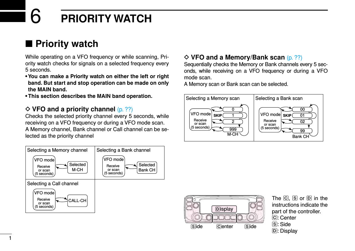
![36PRIORITY WATCHNew2001 New2001New2001VFO and a Memory/Bank scan ■VFO frequency and a Memory/Bank scan DSequentially checks the Memory or Bank channels every 5 seconds, while receiving on a VFO frequency.Set the VFO frequency. q (p. ??)Selects the Memory mode. w (p. ??)Hold down [V/MHz SCAN] eS for 1 second.Rotate [DIAL] rS to select a desired scan type.Push [V/MHz SCAN] tS. •TheMemoryscanstarts.Push [MENU y]C. •EnterstheMENUmode. u Rotate [DIAL]S to select “PRIO” (Priority scan).Push [ iï]D.Rotate [DIAL] oS to select “ON” or “Bell.” •ON:When a signal is received on the priority channel,the channel is automatically selected. •Bell:When a signal is received on the priority channel,the “ ” icon is displayed in the VFO screen.!0 Push [ï]D.!1 Push [MAIN BAND]S. •ExitstheMENUmode. •The“PRIO”iconappears,andthePrioritywatchstarts. •TocancelthePrioritywatch,select“OFF”inthestep!.Example: Sequentially checks the Memory channels while re-ceiving on 433.920 MHz.Checks the Memory channels every 5 seconds.AppearsThe Memory channels are sequentially checked.VFO scan and a Memory/Bank scan DSequentially checks the Memory or Bank channels every 5 seconds during a VFO scan.Operate steps q q through !1 as shown to the left. •The“PRIO”iconappears,andthePrioritywatchstarts.Hold down [V/MHz SCAN] wS for 1 second.Rotate [DIAL] eS to select a desired scan type.Push [V/MHz SCAN] rS. •TheVFOscanstarts.The C, S or D in the instructions indicate the part of the controller.C: Center, S: Side, D: Display](https://usermanual.wiki/ICOM-orporated/359800/User-Guide-2474719-Page-49.png)