ICOM orporated 359800 Dual Band Transceiver User Manual
ICOM Incorporated Dual Band Transceiver
User Manual
This device complies with Part 15 of the FCC Rules. Operation is
subject to the following two conditions: (1) this device may not cause
harmful interference, and (2) this device must accept any interference
received, including interference that may cause undesired operation.
WARNING: MODIFICATION OF THIS DEVICE TO RECEIVE CEL-
LULAR RADIOTELEPHONE SERVICE SIGNALS IS PROHIBITED
UNDER FCC RULES AND FEDERAL LAW.
BASIC MANUAL
New2001
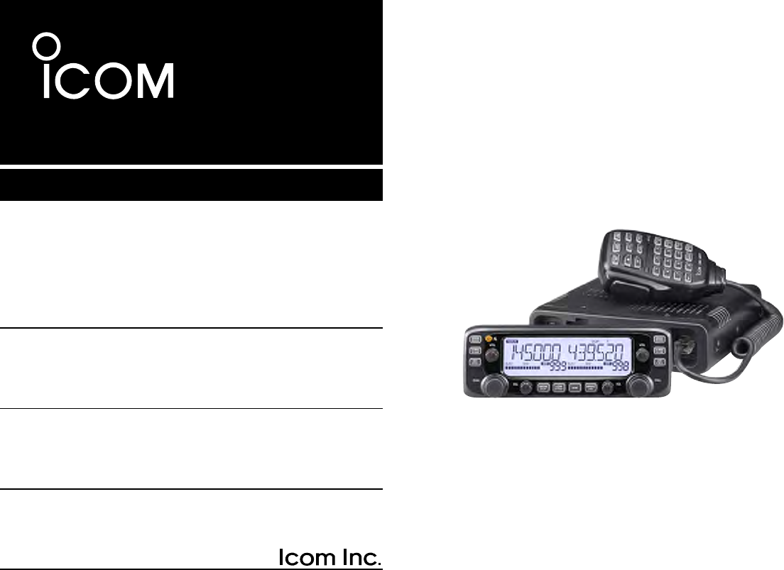
i2730A
DUAL BAND TRANSCEIVER
i2730E
i
New2001New2001
FOREWORD
Thank you for choosing this fine Icom product. The IC-2730A
and IC-2730E v h f /u h f t r a n s c e i v e r are designed and build
with Icom’s superior technology and craftsmanship combin-
ing traditional analog technologies.
With proper care, this product should provide you with years
of trouble-free operation.
We thank you for making your IC-2730A or IC-2730E your
transceiver of choice, and hope you agree with Icom’s philos-
ophy of “technology first.” Many hours or research and devel-
opment went into the design of your IC-2730A or IC-2730E.
EXPLICIT DEFINITIONS
WORD DEFINITION
R DANGER! Personal death, serious injury or an ex-
plosion may occur.
R WARNING! Personal injury, fire hazard or electric
shock may occur.
CAUTION Equipment damage may occur.
NOTE Recommended for optimum use. No risk
of personal injury, fire or electric shock.
IMPORTANT
READ ALL INSTRUCTIONS carefully and completely
before using the transceiver.
SAVE THIS INSTRUCTION MANUAL— This in-
struction manual contains basic operating instructions for the
IC-2730A or IC-2730E.
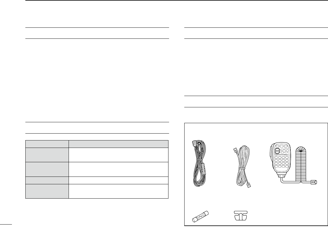
SUPPLIED ACCESSORIES
The following accessories are supplied with the transceiver.
DC power
cable Controller cable
(3.5 m:11.4 ft) Microphone
(HM-207)
Spare fuse
(FGB 15 A) Microphone
hanger

New2001New2001
ii
R DANGER HIGH VOLTAGE! NEVER touch an an-
tenna connector during transmission. This may result in an
electrical shock or burn.
R WARNING RF EXPOSURE! This transceiver emits
Radio Frequency (RF) energy. Extreme caution should be ob-
served when operating this transceiver. If you have any ques-
tions regarding RF exposure and safety standards please
refer to the Federal Communications Commission Office of
Engineering and Technology’s report on Evaluating Compli-
ance with FCC Guidelines for Human Radio Frequency Elec-
tromagnetic Fields (OET Bulletin 65).
R WARNING! NEVER operate the transceiver while
driving a vehicle. Safe driving requires your full attention—
anything less may result in an accident.
R WARNING! NEVER operate the transceiver with an
earphone or other audio accessories at high volume levels.
Continuous high volume operation may cause a ringing in
your ears. If you experience ringing, reduce the volume level
or discontinue use.
R WARNING! NEVER connect the transceiver to an AC
outlet. This may pose a fire hazard or result in an electric
shock.
R WARNING! NEVER connect the transceiver to a
power source of more than 16 V DC such as a 24 V DC. This
could cause a fire or damage the transceiver.
R WARNING! NEVER reverse the DC power cable po-
larity when connecting to a power source. This could damage
the transceiver.
R WARNING! NEVER cut the DC power cable between
the DC plug and fuse holder. If an incorrect connection is
made after cutting, the transceiver may be damaged.
R WARNING! NEVER let metal, wire or other objects
touch any internal part or connectors on the rear panel of the
transceiver. This may result in an electric shock or this could
cause a fire or damage the transceiver.
R WARNING! NEVER operate or touch the transceiver
with wet hands. This may result in an electric shock or may
damage the transceiver.
R WARNING! Immediately turn OFF the transceiver pow-
er and remove the power cable if it emits an abnormal odor,
sound or smoke. Contact your Icom dealer or distributor for
advice.
CAUTION: NEVER expose the transceiver to rain, snow
or any liquids.
PRECAUTIONS

iii
New2001 New2001
CAUTION: NEVER change the internal settings of the
transceiver. This may reduce transceiver performance and/or
damage to the transceiver.
CAUTION: NEVER place the transceiver where normal
operation of the vehicle may be hindered or where it could
cause bodily injury.
DO NOT operate the transceiver near unshielded electrical
blasting caps or in an explosive atmosphere.
DO NOT push the PTT when not actually desiring to trans-
mit.
DO NOT use harsh solvents such as benzine or alcohol to
clean the transceiver, as they will damage the transceiver’s
surfaces. If the transceiver becomes dusty or dirty, wipe it
clean with a soft, dry cloth.
DO NOT use or place the transceiver in areas with tem-
peratures below –10°C (+14°F) or above +60°C (+140°F). Be
aware that temperatures on a vehicle’s dashboard can exceed
+80°C (+176°F) in direct sunlight, resulting in permanent dam-
age to the transceiver if left there for extended periods.
DO NOT place the transceiver in excessively dusty environ-
ments or in direct sunlight.
DO NOT place the transceiver against walls or putting anything
on top of the transceiver. This will obstruct heat dissipation.
Place the transceiver in a secure place to avoid inadvertent
use by children.
During mobile operation, NEVER place the transceiver
where air bag deployment may be obstructed.
During mobile operation, DO NOT place the transceiver
where hot or cold air blows directly onto it.
During mobile operation, DO NOT operate the transceiver
without running the vehicle’s engine. When the transceiver’s
power is ON and your vehicle’s engine is OFF, the vehicle’s
battery will soon become exhausted.
Make sure the transceiver power is OFF before starting the
vehicle engine. This will avoid possible damage to the trans-
ceiver by ignition voltage spikes.
During maritime mobile operation, keep the transceiver and
microphone as far away as possible from the magnetic navi-
gation compass to prevent erroneous indications.
BE CAREFUL! The rear panel will become hot when op-
erating the transceiver continuously for long periods of time.
Use Icom microphones only (supplied or optional). Other
manufacturer’s microphones have different pin assignments,
and may damage the transceiver.
PRECAUTIONS (Continued)

New2001
iv
TABLE OF CONTENTS
FOREWORD ......................................................................... i
EXPLICIT DEFINITIONS .......................................................i
IMPORTANT .......................................................................... i
SUPPLIED ACCESSORIES ................................................. ii
IMPORTANT NOTES ............................................................ ii
ABOUT THE TOUCH SCREEN ........................................... iii
ABOUT THE SUPPLIED CD ................................................ v
PRECAUTIONS ................................................................... vi
TABLE OF CONTENTS ......................................................viii
NEW FUNCTIONS ....................................... x–xii
1 PANEL DESCRIPTION ........................... 1–10
Controller — Front panel ■ .............................................1
Controller — Display (Touch screen) ■ ..........................2
Main unit — Front and rear panels ■ .............................7
Microphone (HM-207) ■ .................................................8
2 BASIC OPERATION .............................. 11–18
Power ON the power ■ .................................................11
Setting audio volume and squelch level ■ ....................11
Selecting a tuning step ■..............................................11
Selecting the watch mode ■ .........................................12
Selecting the operating band ■ ....................................13
Direct frequency input ■ ...............................................14
Selecting the Mode and the DR function ■ ..................15
Transmitting ■ ...............................................................16
Selecting the operating mode ■ ...................................17
Lock function ■ .............................................................17
Home channel function ■ .............................................18
Speech function ■ ........................................................18
3 MEMORY MANAGEMENT .................... 19–20
Writing Memory channels ■ .........................................19
Checking the Memory contents ■ ................................19
4 D-STAR OPERATION ............................ 21–54
Unique features of D-STAR ■ .......................................21
D-STAR Introduction ■ .................................................22
About the DR (D-STAR Repeater) function ■ ...............22
Ways to Communicate with the DR function ■ .............23
Enter your call sign into the transceiver ■ ....................24
Register your call sign at a gateway repeater ■ ...........27
Making a Simplex call ■ ...............................................29
Accessing repeaters ■ .................................................31
Using the RX history ■ .................................................33
Capturing a call sign ■ .................................................35
Making a Local area call ■ ...........................................37
Making a Gateway Repeater call ■ ..............................39
Calling an individual station ■ ......................................41

New2001
v
New2001
TABLE OF CONTENTS (Continued)
Troubleshooting ■ .........................................................43
Reflector operation ■ ....................................................45
Updating the repeater list ■ ..........................................51
5 RECORDING A QSO ONTO
AN SD CARD ........................................ 55–58
About the SD card ■.....................................................55
Inserting the SD card ■ ................................................56
Recording a QSO audio ■ ............................................57
Playing recorded audio ■ .............................................58
Removing the SD card ■ ..............................................58
6 GPS OPERATION ................................. 59–60
GPS operation ■ ..........................................................59
Checking your GPS position ■ .....................................59
7 MENU SCREEN .................................... 61–78
Menu item selection ■ ..................................................61
Menu items and Default settings ■ ...............................62
8 INSTALLATION AND CONNECTIONS . 79–84
Connect controller to main unit ■ .................................79
Microphone connection ■ .............................................79
DC power supply connection ■ ....................................79
Controller ■ installation ................................................80
Installing in a vehicle ■ .................................................81
Antenna installation ■...................................................82
Battery connection ■ ....................................................83
9 MAINTENANCE .................................... 85–86
Resetting ■ ...................................................................85
Power protect function ■ ..............................................86
Spurious signals ■ .......................................................86
Fuse replacement ■ .....................................................86
10 INFORMATION ............................................ 87
COUNTRY CODE LIST .................................................87
FCC INFORMATION ......................................................87
INDEX ......................................................... 88–90
Icom, Icom Inc. and the Icom logo are registered trademarks of Icom
Incorporated (Japan) in Japan, the United States, the United King-
dom, Germany, France, Spain, Russia and/or other countries.
Microsoft, Windows and Windows Vista are registered trademarks of
Microsoft Corporation in the United States and/or other countries.
The Bluetooth word mark and logos are registered trademarks
owned by Bluetooth SIG, Inc. and any use of such marks by Icom
inc. is under license.
All other products or brands are registered trademarks or trademarks
of their respective holders.
New2001
1
1
PANEL DESCRIPTION
New2001
1
PANEL DESCRIPTION
e
r
t
yuiuy
q
w
e
r
t
w
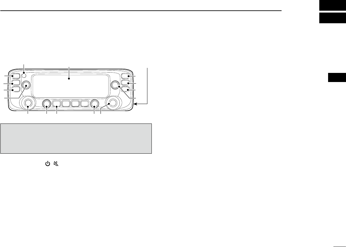
Controller — Front panel ■
q POWER KEY [ ]( )
Hold down for 1 second to turn power ON or OFF. ➥(p.
??)
Push to mute the audio. ➥(p. ??)
wMAIN•BANDKEY[MAINBAND]
Push to select the MAIN band. (p. ??)
In the VFO mode
Hold down for 1 second to enter the Operating band select
mode. (p. ??)
In the Memory mode
Hold down for 1 second to enter the Memory bank select
mode. (p. ??)
eVFO/MHzTUNING•SCANKEY[V/MHzSCAN]
Push to select the VFO mode. ➥
In the VFO mode, push to select 1 MHz ➥ tuning. (p. ??)
Hold down for 1 second to enter the Scan type select ➥
mode. (p. ??)
rMEMORY•CALLKEY[MRCALL]
Push to select the Memory mode. ➥(p. ??)
In the VFO mode, push to select the Weather channel ➥
mode.* (p. ??)
*Weather channels available for USA versions only.
Hold down for 1 second to select the Call channel ➥
mode. (p. ??)
t VOLUME CONTROL (p. ??)
y TUNING DIAL [DIAL]
In the VFO mode
Rotate to select the operating frequency. (p. ??)
In the Memory mode
Rotate to select Memory channel. (p. ??)
While scanning
Rotate to change the scanning direction. (p. ??)
In the MENU mode
Rotate to select a desired option or value. (p. ??)
u SQUELCH CONTROL (p. ??)
Rotate to adjust the squelch level.
iMONITOR•DUPLEXKEY[DUPMONI]
Push to turn the Monitor function ON and OFF. ➥(p. ??)
Push and hold for 1 second to select DUP–, DUP+, or ➥
simplex operation. (p. ??)
Display (p. ?)
Microphone
connector (p. ?)
For your reference:
The key-touch beep tones on the left band are different than
the tones on the right band. The different tones will let you
know which band you are operating.
2
1PANEL DESCRIPTION
New2001 New2001
New2001
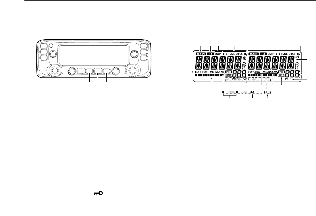
Controller — Display (Continued) ■
oOUTPUTPOWER•DTMFKEY[LOWDTMF]
Push to ➥select the transmit output power level. (p. ??)
Hold down for 1 second to turn DTMF memory encoder ➥
ON and OFF. (p. ??)
!0 MEMORY WRITE KEY [MW]
In the VFO mode
Push to display the Memory write screen. ➥(p. ??)
Hold down for 1 second to store the operating frequen- ➥
cy into a blank Memory channel.
In the Memory mode
Push to display the Memory channel entry screen. ➥(p.
??)
Hold down for 1 second to display the Memory channel ➥
setting screen. (p. ??)
!1 MENU LOCK KEY [MENU ]
Push to enter the MENU mode. ➥
Hold down for 1 second to turn the Lock function ON ➥
or OFF.
Controller — Display ■
q MAIN ICON
Displayed on the MAIN band. (p. ??)
•YoucantransmitonlyontheMAINband.
•TheMENUmodesettingsarefortheMAINband.
w TX ICON (p. ??)
e DUPLEX ICON (p. ??)
Displayed while in the duplex mode.
r TONE ICONS (p. ??)
t Bluetooth® ICON (p. ??)
Displayed when you make a Bluetooth® connection be-
tween your transceiver* and a Bluetooth® device.
*Requires an optional UT-133 Bluetooth® u n i t installed.
y KEY LOCK ICON (p. ??)
Displayed when a key or controller is locked.
!0!1
!8 !7!9
!2!3!4!5
!6
q w e r t y
u
i
o
o !0 !1

New2001
3
1
PANEL DESCRIPTION
New2001
1
PANEL DESCRIPTION
u FREQUENCY READOUT (p. ??)
i MEMORY CHANNEL NUMBER (p. ??)
Displays the selected Memory channel number, Memory
Bank number, Call channel number, or Menu item name.
o PRIORITY ICON (p. ??)
Displayed when the Priority watch is turned ON.
!0 SKIP ICON (p. ??)
Appears when the displayed Memory channel is specified
as a skip channel.
!1 MODE ICON (p. ??)
!2 POWER ICON (p. ??)
!3 VOX ICON (p. ??)
Displayed when the transceiver is connected to the op-
tional VS-3 Bluetooth® h e a d s e t , and the VOX function is
ON.
!4 MEMORY MODE ICON (p. ??)
!5 S/RF METER
Displays the relative signal strength of the receive sig- ➥
nal. (p. ??)
Displays the output power level of the transmit signal. ➥
(p. ??)
!6 BUSY ICON
Displayed while a signal is being received or the squelch ➥
is open. (p. ??)
Blinks while the Monitor function is activated. ➥(p. ??)
!7 CLEAR KEY [CLR]
In the MENU mode
Push [MENU ] to return to the previous screen. (p. ??)
While entering text
Push [MENU ➥] to delete the selected character,
symbol or number. (p. ??)
Hold down [MENU ➥] for 1 second to delete the se-
lected character, symbol or number, and all characters
that are located to the right of the cursor. (p. ??)
!8 ENTER KEY [ï]
Push [MW] to go to the next tree level or to set the option
or value in the MENU mode. (p. ??)
!9 LEFT/RIGHT KEYS [Ω]/[≈]
In the MENU mode
[Ω]: Push [MONI DUP] to go back the previous tree level.
(p. ??)
[≈]: Push [LOW DTMF] to go to the next tree level. (p. ??)
4
1PANEL DESCRIPTION
New2001 New2001
New2001
Main unit ■
q CONTROLLER CONNECTOR [CONTROLLER] (p. ??)
Connects to the Controller using the supplied control cable.
w MICROPHONE CONNECTOR [MIC]
Plug in the supplied HM-207 microphone or the optional
HM-154 microphone.
e ANTENNA CONNECTOR (p. ??)
Connect a 50 ø impedance antenna with a PL-259 con-
nector.
The transceiver has a built-in duplexer, so you can use a
144 and 430 MHz dual-band antenna without needing an
external duplexer.
r COOLING FAN
The cooling fan for heat dissipation.
You can select the Fan control option in the Menu screen,
to automatically start rotating when you begin transmitting,
or continuously rotate from power ON. (p. ??)
t DC POWER SOCKET [DC 13.8V]
Connect a 13.8 V DC power source through the supplied
DC power cable.
y EXTERNAL SPEAKER JACK 2 [SP2]
u EXTERNAL SPEAKER JACK 1 [SP1]
Connect an 8 ohm external speaker.
•Seethefollowinglistforthespeakerconnectionandaudioout-
put details.
Ex. speaker
connection
status
Audio output
External speaker Internal speaker
SP-1 SP-2
SP-1 and SP-2 Left band Right band –
SP-1 only Both bands – –
SP-2 only –Right band Left band
Microphone connector information D
12345678
Front panel
view
1 8 V +8 V DC output
Maximum 10 mA
2 MIC U/D Frequency Up/Down
UP: Ground
DN: Ground through 470 ˘
3 M8V SW HM-207 connection
Grounds when the HM-207 is connected.
4 PTT PTT input
Ground for transmission
5 MIC E Microphone ground
6 MIC Microphone input
7 GND PTT ground
8 DATA IN
Inputs HM-207 data when the HM-207
is connected.
q w e r
t
yu
Front panel Rear panel

New2001
5
1
PANEL DESCRIPTION
New2001
1
PANEL DESCRIPTION
With the HM-207, you can input numbers for frequency or
Memory channel settings, and adjust the audio volume and
squelch level.
q
w
e
!0
t
y
i
u
o
r
Mic element
q LED 1
Lights red while transmitting by pushing [PTT].
w [∫]/[√] (UP/DOWN) KEYS
Push to change the operating frequency or Memory ➥
channel.
Hold down to continuously change the frequency or ➥
Memory channel.
e [PTT] SWITCH
Hold down to transmit, release to receive.
r [VFO/MR ] KEY
Push to toggle between the VFO and Memory modes. ➥
Hold down for 1 second to turn the Lock function ON ➥
or OFF. (p. ??)
t [HOME CALL] KEY
Push to select the Home channel. ➥
Hold down for 1 second to turn the Call channel mode ➥
ON or OFF.
y [MAIN DUAL] KEY
Push to toggle between the MAIN and SUB bands.
u [F-1] KEY
Push to activate the preset function of the [F-1] key.
(Default: During RX/Standby: [BAND/BANK]
During TX: [T-CALL])
[F-2] KEY
Push to activate the preset function of the [F-2] key.
(Default: During RX/Standby: [Monitor]
During TX: [---])
You can assign a desired function in the MENU mode. (p.
??, ??)
i [CLR] KEY
In the Menu screen or Quick Menu window, push to return
to the standby screen.
o [ENT] KEY
After entering a VFO frequency or memory channel num-
ber, push to set.
!0 LED 2
Lights green when transceiver’s power is ON.
About the HM-207 microphone ■
6
1PANEL DESCRIPTION
New2001 New2001
New2001
!1 [VOL∫ A] KEY
Push to increase the audio output level. ➥
When entering a DTMF code, push to input ‘A.’ ➥
!2 [VOL√ B] KEY
Push to decrease the audio output level. ➥
When entering a DTMF code, push to input ‘B.’ ➥
!3 [SQL∫ C] KEY
Push to increase the squelch level. ➥
When entering a DTMF code, push to input ‘C.’ ➥
!4 [SQL√ D] KEY
Push to decrease the squelch level. ➥
When entering a DTMF code, push to input ‘D.’ ➥
!5 [# CE] KEY
In the frequency entry screen, push to delete a num- ➥
ber.
When entering a DTMF code, push to input ‘#.’ ➥
!6 [M .] KEY
In the frequency entry screen, push to input a ‘.’ (deci- ➥
mal point).
When entering a DTMF code, push to input ‘ ➥M.’
!7 [0] to [9] KEYS
In the frequency entry window or while entering a DTMF
code, push to input ‘0’ through ‘9.’
Setting frequency and Memory channel D
[Example for setting the frequency]
First, push [VFO/MR ] to select the VFO mode.
To enter 435.680 MHz:
Push [4], [3], [5], [6], [8], [0], then [ENT]. ➥
To change 435.680 MHz to 435.540 MHz:
Push[•],[5],[4],[0],then[ENT]. ➥
To enter 433.000 MHz:
Push [4], [3], [3], then [ENT]. ➥
[Example for setting the Memory channel]
To select the Memory channel ‘5’:
First, push [VFO/MR ] to select the Memory mode, and
then push [5] then [ENT].
[Example for setting the Call channel]
To select the ‘0’ or ‘1’ Call channel:
First, hold down [HOME CALL] for 1 second to select the Call
channel mode, and then push [∫] or [√].
Microphone (HM-207) (Continued) ■
!7
!6
!1
!2
!3
!4
!5
New2001
7
1
PANEL DESCRIPTION
New2001
1
PANEL DESCRIPTION
The following functions can be set to [F-1] and [F-2] to use during receive or in stand-by, or during TX.
During RX/Standby:
Function Description
--- No function
Monitor
([F2] key: Default)
Push to open or close the squelch.
MR (000 CH) In the Memory mode, push to select Memo-
ry channel 000.
MR (001 CH) In the Memory mode, push to select Memo-
ry channel 001.
BAND/BANK
([F1] key: Default)
Push to select an operating band.
In the VFO mode, push to change the oper-
ating band, and in the Memory Bank mode,
push to select Bank A to J, or OFF.
•Onlytheprogrammedbankappears.
SCAN Push to start a scan.
While scanning, push to stop the scan.
Temporary
Skip
Push to set the frequency to be skipped dur-
ing scanning.
The selected frequencies are temporarily
skipped for faster scanning.
MODE Push to change the operating mode.
LOW Push to change the transmit power level.
DUP Push to turn the Duplex mode ON or OFF,
and the shift direction to DUP+ or DUP–.
PRIO
Push to turn the Priority watch ON or OFF.
TONE/DSQL Push to toggle between tone types.
Function Description
MW
In the VFO mode, hold down for 1 second
to save the frequency displayed in the MAIN
band into a Memory channel.
•Thefrequencyisautomaticallysavedinablank
channel.
MUTE Push to turn the Mute function ON or OFF.
DTMF
DIRECT TX Push to display the DTMF code direct entry
mode screen.
T-CALL Push to transmit a 1750 Hz tone.
During TX:
Function Description
---
([F2] key: Default)
No function
LOW Push to change the transmit power level.
Voice TX
Push to transmit the voice audio recorded
on the SD card once.
Hold down for 1 second to repeatedly trans-
mit the voice audio.
•Tomakearepeattransmission,[PTT]mustbe
released.
T-CALL
([F1] key: Default)
Push to transmit a 1750 Hz tone.
1
New2001New2001
MENU MODE
2
New2001
The Menu mode is used to program infrequently changed val-
ues or function settings.
The Menu mode items are activated on the Main band.
In addition to this page, see pages ?? through ?? for details
of each item’s options and their default value.
For your reference: The Menu system is constructed in a
tree structure. You may go to the next tree level, or go back
a level, depending on the selected item.
Selecting the Menu item ■
Example: Set the tuning step
Push [MAIN BAND] qS of the band that the tuning step is
set.
•SelectstheMainband.
Push [MENU w]C.
•EnterstheMenumode.
e Rotate [DIAL]S to select the “MENU-TS” (Tuning step)
item.
To return to the default setting:
Hold down [MR CALL] after step r operation.
Push [ rï]D.
•Goestothenexttreelevel.
•Pushing[≈]D also goes to the next tree level.
Rotate [DIAL] tS to select the desired value.
Selectable values:
5 kHz, 6.25 kHz, 8.33 kHz*, 10 kHz, 12.5 kHz, 15 kHz,
20 kHz, 25 kHz, 30 kHz, 50 kHz or Auto*.
*Appears only when the AIR band is selected.
Push [ yï]D.
•Setstheselectedvalue,andgoesbacktotheprevioustreelev-
el.
•Pushing[Ω]D also goes back to the previous tree level.
Push [MAIN BAND] uS.
•ExitstheMenumode.
•Pushing[V/MHz SCAN]S or [MR CALL]S also exits the Menu
mode.
Side Side
Display
Center
The C, S or D in the
instructions indicate the
part of the controller.
C: Center
S: Side
D: Display
New2001
2
2
MENU MODE
New2001
2
MENU MODE
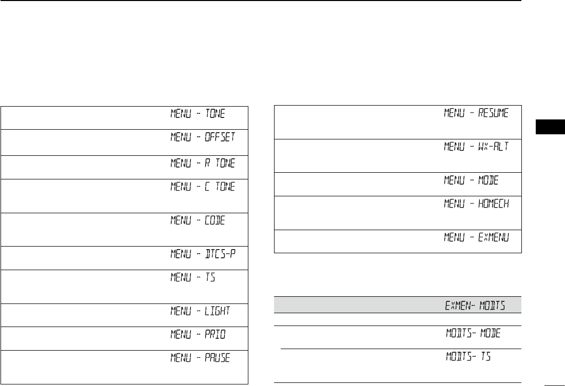
Setting items ■
Menu mode D
See pages ?? to ?? for details of the Menu mode items.
Tone
Sets a channel tone type.
Offset Freq
Sets the frequency offset for duplex (repeater) operation.
Repeater Tone
Sets a tone frequency used to access the repeaters.
TSQL Freq
Sets a tone frequency for the Tone squelch function used in the FM
mode.
DTCS Code
Sets a DTCS (both encoder/decoder) code for DTCS squelch func-
tion used in the FM mode.
DTCS Polarity
Sets the DTCS polarity for the DTCS squelch function.
Tuning step
Sets the tuning step to change the frequency by rotating [DIAL] in
the selected step.
LCD Backlight
Sets the backlight brightness level.
Priority scan
Starts or stops the Priority scan.
Pause Timer
Sets the scan pause time. When receiving signals, the scan pauses
according to the scan pause timer.
Resume Timer
Sets the scan resume time from a pause after the received signal
disappears.
Weather alert
Sets to sound a beep when a weather alert signal is detected on a
preset weather channel.
Operating mode
Sets the operating mode.
Home CH
Sets the often-used frequency as the Home channel in the VFO
mode or Memory mode.
EX Menu mode
Enters the EX Menu mode.
EX Menu mode D
See the Icom website for details of the EX Menu mode items.
Mode and Tuning step items
Sets the operating mode and the tuning step.
Operating mode*
Sets the operating mode.
Tuning step*
Sets the tuning step to change the frequency in the selected step
when rotating [DIAL].
3
2MENU MODE
New2001 New2001
New2001
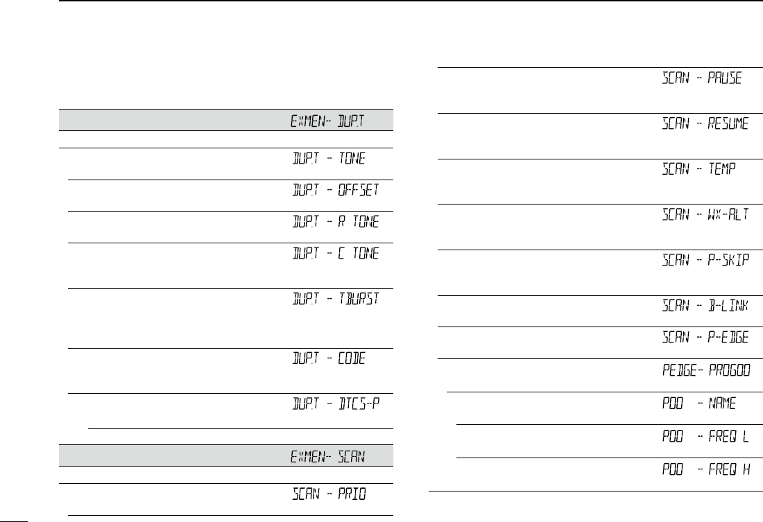
DUP/TONE items
Settings to access repeaters.
Tone*
Sets a channel tone type.
Offset Freq*
Sets the frequency offset for duplex (repeater) operation.
Repeater Tone*
Sets a tone frequency used to access the repeaters.
TSQL Freq*
Sets a tone frequency for the Tone squelch function used in the
FM mode.
Tone Burst
Turns the Tone Burst function ON or OFF.
This function is used to suppress the squelch tail noise heard from
the transceiver’s speaker.
DTCS Code*
Sets a DTCS (both encoder/decoder) code for DTCS squelch
function used in the FM mode.
DTCS Polarity*
Sets the DTCS polarity for the DTCS squelch function.
Scan items
Set scan options.
Priority scan*
Starts or stops the Priority scan.
Pause Timer*
Selects the scan pause time. When receiving signals, the scan
pauses according to the scan pause timer.
Resume Timer*
Selects the scan resume time from a pause after the received sig-
nal disappears.
Temporary Skip Timer
Selects the Temporary Skip Time. When the time is set, specified
frequencies are skipped for this period during a scan.
Weather alert
Sets to sound a beep when a weather alert signal is detected on a
preset weather channel.
Program Skip
Turns the Program Skip Scan function ON or OFF for a VFO mode
scan.
Bank Link
Selects banks to be scanned during a Bank Link Scan.
Program Scan Edge
Sets the frequency ranges for the program scan.
Program Scan Edge
Sets the frequency range for the program scan.
Name
Enters a name into each Program scan edge.
Freq Low
Set the lower edge frequency for the Program scan edge.
Freq High
Set the higher edge frequency for the Program scan edge.
Setting items ■
EX Menu mode (Continued) D
New2001
4
2
MENU MODE
New2001
2
MENU MODE
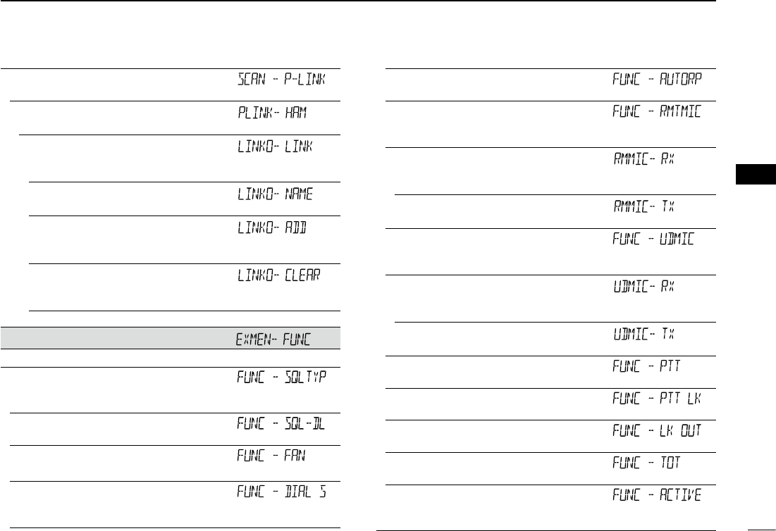
Program Link
Sets the link function for the program scan edge channels.
Program Scan Link channels
Displays a maximum of 10 Program Scan Link channels.
Link
Displays the Program Scan channels that are scanned during
the Program Link scan.
Name
Enters a name into each Program Scan channel.
Add
Adds the Program Scan channel that is scanned during the
Program Link scan.
Clear
Deletes the Program Scan channel that is scanned during the
Program Link scan.
Function items
Sets various function’s options.
Squelch/ATT Select
Sets to use the S-Meter Squelch or the Attenuator function for the
[SQL] control.
Squelch Delay
Sets the squelch delay to short or long until the squelch opens.
Fan Control
Sets the cooling fan control condition.
Dial Speed-UP
Sets to automatically speeds up the tuning dial speed when rapidly
rotating [DIAL].
Auto Repeater*
Turns the Auto Repeater function ON or OFF.
Remote MIC Key
Selects the key function for [F-1] or [F-2] on the supplied HM-207
remote-control microphone.
During RX/Standby
Selects the key function to be used while receiving or in the
standby mode.
During TX
Selects the key function to be used while transmitting.
Up/Down MIC Key
Selects the key function for [UP] or [DN] on the optional HM-154
hand microphone.
During RX/Standby
Selects the key function to be used while receiving or in the
standby mode.
During TX
Selects the key function to be used while transmitting.
One-Touch PTT
Turns the One-Touch PTT function ON or OFF.
PTT Lock
Turns the PTT Lock function ON or OFF.
Busy Lockout
Turns the Busy Lockout function ON or OFF.
Time-Out Timer
Selects the Time-Out Timer time options.
Active Band
Allows continuous frequency selection across all bands by rotat-
ing [DIAL].
5
2MENU MODE
New2001 New2001
New2001
Function items (Continued)
MIC Gain
Sets the microphone sensitivity to suit your preference.
Auto Power OFF
Sets to automatically turn OFF the transceiver after a preset time
period of inactivity.
CI-V
CI-V Address
Sets the transceiver’s unique CI-V hexadecimal address code.
CI-V Baud Rate
Sets the CI-V code transfer speed.
CI-V Transceive
Turns the CI-V Transceive function ON or OFF.
IF Exchange
Sets to exchange the Intermediate Frequency to prevent interfer-
ence.
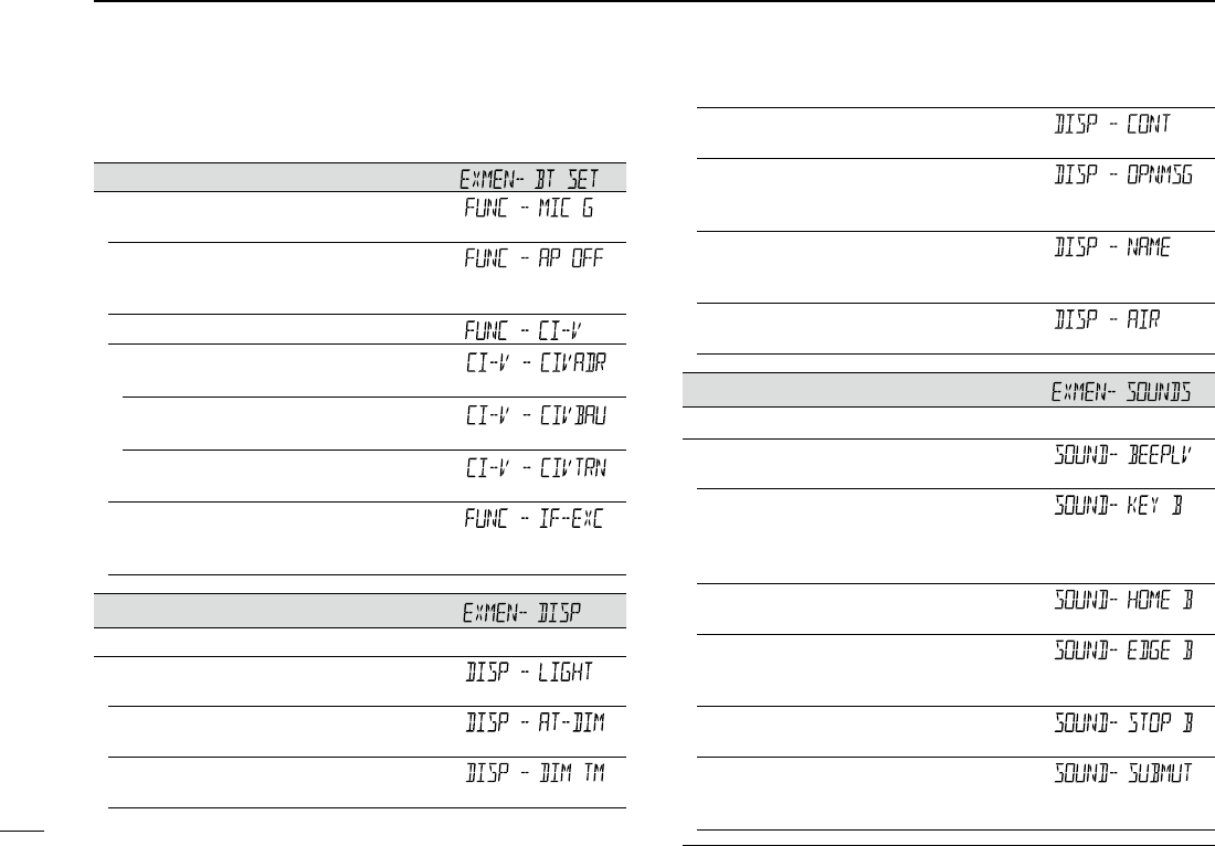
Display items
Sets the Display options.
LCD Backlight*
Sets the backlight brightness level.
Auto Dimmer
Sets the Auto dimmer function, and the dimmer level.
Auto Dimmer Timer
Sets the backlight lighting time period.
LCD Contrast
Sets the contrast level of the LCD.
Opening Message
Sets whether or not to display “ICOM” and power source voltage
at power ON.
Memory Name
Sets to display either the operating frequency or the channel name
for the Memory mode.
AIR Band Display
Sets the display type of the VHF AIR band frequency.
Sound items
Sets the Sound options.
Beep Level
Sets the beep output level.
Key-Touch Beep
Sets to sound a beep when you push a key.
•Thebeeptonesaredifferentbetweenontheleftbandandthe
right band.
Home CH Beep
Sets to sound a beep when you select the Home CH.
Band Edge Beep
Sets to sound a beep when you tune into or out of the AIR, VHF
and UHF band’s frequency range by rotating [DIAL].
Scan Stop Beep
Sets to sound a beep when a scan stops by receiving a signal.
Sub Band Mute
Sets to mute the SUB band audio signal while receiving on the
MAIN band.
Setting items ■
EX Menu mode D
New2001
6
2
MENU MODE
New2001
2
MENU MODE
Home CH items*
Sets the often-used frequency as the Home channel in the VFO
mode or Memory mode.
Setting
Sets a displayed frequency as a Home channel.
Clear
Cancels the current Home channel.
This item does not appear when no Home channel is set.
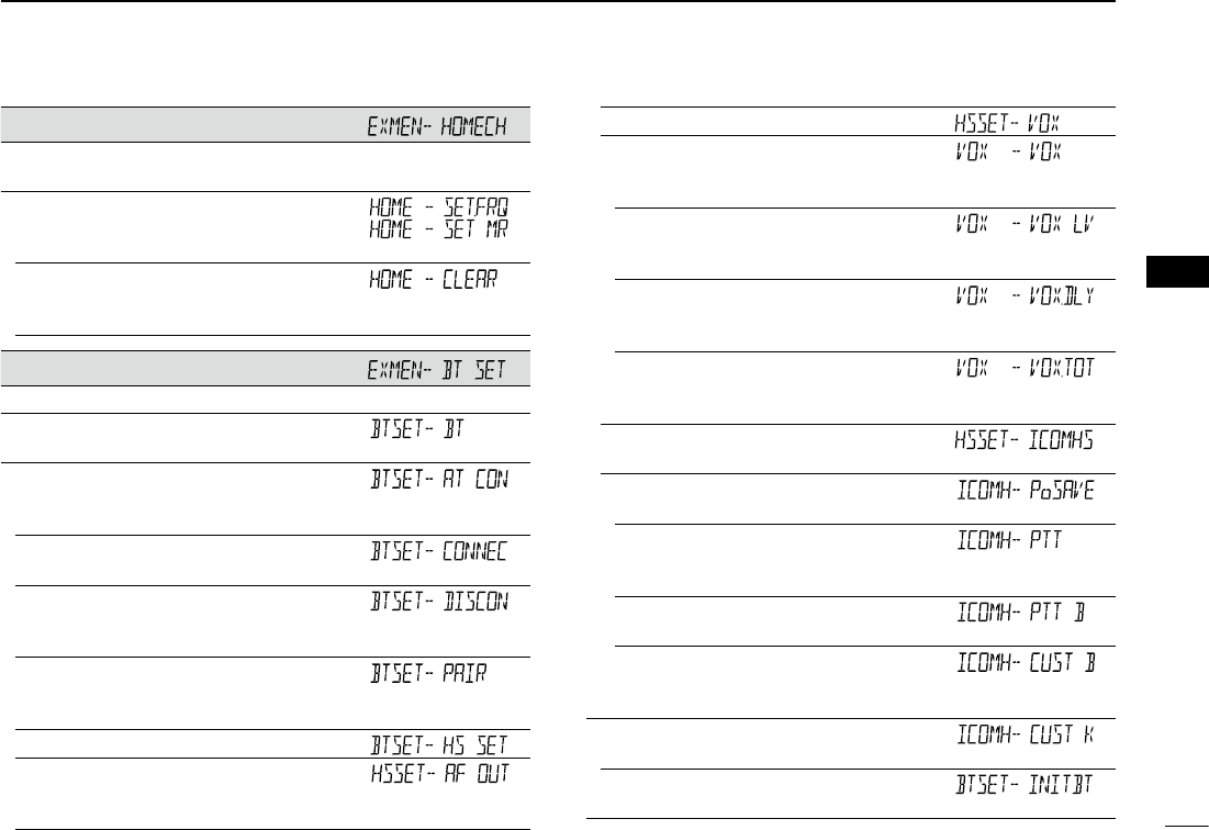
Bluetooth® items
Sets the Bluetooth® options.
Bluetooth®
Turns the Bluetooth® function ON or OFF.
Auto Connect
Sets to automatically connect to the paired Bluetooth® device
when its device is ON.
Bluetooth® connection
Displays the connected Bluetooth® device.
Bluetooth® disconnection
Disconnects from the connected Bluetooth® device without can-
celling the pairing.
Paring/Connect
Searches for the Bluetooth® device to connect, or view the paired
Bluetooth® devices in the list.
Headset Set
AF Output
Selects the AF output option for when you use the Bluetooth®
headset.
VOX
VOX
Sets the VOX (Voice Operated Transmission) function for when
you use the Bluetooth® headset.
VOX Level
Set the VOX gain level.
Higher values make the VOX function more sensitive to your voice.
VOX Delay
Sets the VOX Delay time for the transmitter stays ON after you
stop speaking before the VOX switches to receive.
VOX Time-Out Timer
Sets the VOX Time-Out Timer to prevent an accidental prolonged
transmission.
Icom Headset
Sets to use the optional Icom Bluetooth® headset (VS-3).
Power Save
Sets the Power save function to prolong the headset battery.
One-Touch PTT
Sets the One-Touch PTT function to toggle between transmis-
sion and reception by pushing [PTT].
PTT Beep
Sets to sound a beep when you push [PTT].
Custom Key Beep
Sets to sound a beep when you push the custom key ([PLAY]/
[FWD]/[RWD]).
Custom Key
Sets the key function of the custom key ([PLAY]/[FWD]/[RWD]).
Initialize Bluetooth Device
Selects to reset the optional UT-133 Bluetooth® unit.
7
2MENU MODE
New2001 New2001
New2001
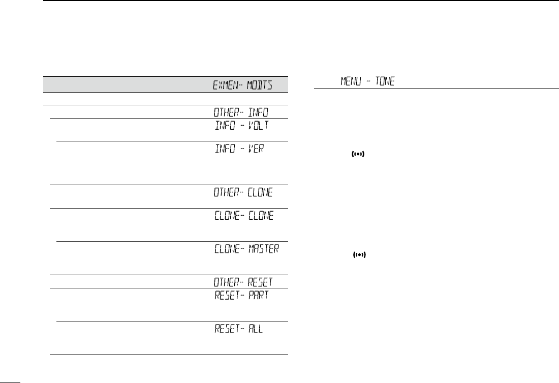
Other items
Set other options.
INFORMATION
Voltage
Displays the voltage of the external DC power source.
Version
Displays the transceiver’s firmware version number.
•TheBluetoothunitversionisalsodisplayedwhentheoptional
UT-133 Bluetooth® unit is installed.
CLONE
Sets the clone mode.
Clone Mode
Sets the transceiver as a Sub transceiver to receive data from a
Master transceiver.
Clone Master Mode
Sets the transceiver as a Master transceiver to send data to a
Sub transceiver.
Reset
Partial Reset
Returns all settings to their defaults, without clearing the mem-
ory contents.
All Reset
Clears all programming and memories, and return all settings to
their defaults.
Setting items ■
EX Menu mode (Continued) DMenu items ■
Tone (Default: OFF)
Select a desired channel tone type.
•OFF: ThefunctionisOFF.
•TONE: The selected subaudible tone is superimposed
on your normal signal.
Subaudible tone setting: “MENU-R TONE”
•TSQL(“ ” appears):
Enables the tone squelch with the pocket beep
function.
•TSQL: Enablesthetonesquelchfunction.
When you transmit, the selected tone frequency
is superimposed on your normal signal.
The tone squelch opens only when you receive a
signal that includes a matching tone frequency.
Tone frequency setting: “MENU-C TONE”
•DTCS(“ ” appears):
Enables the DTCS squelch with the pocket beep
function.
•DTCS: EnablestheDTCSsquelchfunction.
When you transmit, the selected DTCS code is
superimposed on your normal signal.
The DTCS squelch opens only when you receive
a signal that includes a matching DTCS code.
DTCS code setting: “MENU-CODE”
“MENU-DTCS-P”

New2001
8
2
MENU MODE
New2001
2
MENU MODE
•TSQL-R: Enablesthereversetonesquelchfunction.
When you transmit, the selected CTCSS tone is
not superimposed on your normal signal.
The tone squelch opens only when you receive
a signal that includes a non-matching subaudible
tone.
•DTCS-R: EnablesthereverseDTCSsquelchfunction.
When you transmit, the selected DTCS code is
not superimposed on your normal signal.
The DTCS squelch opens only when you receive
a signal that includes a non-matching DTCS
code.
DTCS code setting: “MENU-CODE”
“MENU-DTCS-P”
•DTCS(T):When you transmit, the selected DTCS code is
superimposed on your normal signal.
When you receive, the function is OFF.
DTCS code setting: “MENU-CODE”
“MENU-DTCS-P”
•TONE(T)/DTCS(R):
When you transmit, the selected subaudible tone
is superimposed on your normal signal.
When you receive, the DTCS squelch opens only
for a signal that includes a matching DTCS code.
Subaudible tone setting: “MENU-R TONE”
DTCS code setting: “MENU-CODE”
“MENU-DTCS-P”
•DTCS(T)/TSQL(R):
When you transmit, the selected DTCS code is
superimposed on your normal signal.
The tone squelch opens only when you receive a
signal that includes a matching tone frequency.
DTCS code setting: “MENU-CODE”
“MENU-DTCS-P”
Tone frequency setting: “MENU-C TONE”
•TONE(T)/TSQL(R):
When you transmit, the selected subaudible tone
is superimposed on your normal signal.
The tone squelch opens only when you receive a
signal that includes a matching tone frequency.
Subaudible tone setting: “MENU-R TONE”
Tone frequency setting: “MENU-C TONE”
Offset frequency (Default: 0.600.00*)
Set the frequency offset for duplex (repeater) operation to be-
tween 0 and 59.99500 MHz.
•Theduplexshiftdirection(DUP–/DUP+)issetintheduplex
setting screen that is displayed when you hold down [MONI
DUP] for 1 second in the VFO mode. (p. ??)
* The default value may differ, depending on the frequency
band (selected as the Main band before entering the Menu
mode) and the transceiver version.
9
2MENU MODE
New2001 New2001
New2001
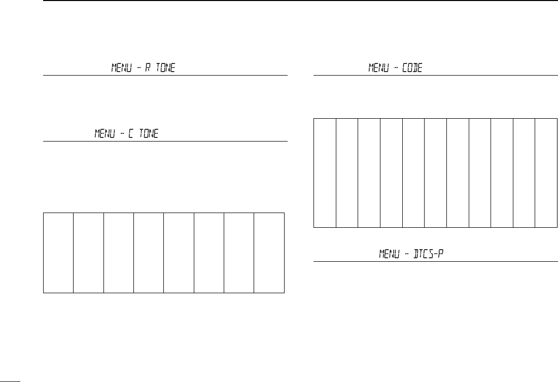
Repeater Tone (Default: 88.5)
Select a CTCSS tone frequency for repeater access and
other functions. 50 tone frequencies (67.0~254.1 Hz) are se-
lectable.
TSQL Freq (Default: 88.5)
Select a CTCSS tone frequency for the tone squelch or the
Pocket beep function.
50 frequencies (67.0~254.1 Hz) are selectable.
•Selectablerepeatertone/tonesquelchfrequencies
(Unit: Hz)
67.0
69.3
71.9
74.4
77.0
79.7
82.5
085.4
088.5
091.5
094.8
097.4
100.0
103.5
107.2
110.9
114.8
118.8
123.0
127.3
131.8
136.5
141.3
146.2
151.4
156.7
159.8
162.2
165.5
167.9
171.3
173.8
177.3
179.9
183.5
186.2
189.9
192.8
196.6
199.5
203.5
206.5
210.7
218.1
225.7
229.1
233.6
241.8
250.3
254.1
DTCS Code (Default: 023)
Select a DTCS (both encoder/decoder) code for the DTCS
squelch. A total of 104 codes (023
~
754) are selectable.
•SelectableDTCScodes
023
025
026
031
032
036
043
047
051
053
054
065
071
072
073
074
114
115
116
122
125
131
132
134
143
145
152
155
156
162
165
172
174
205
212
223
225
226
243
244
245
246
251
252
255
261
263
265
266
271
274
306
311
315
325
331
332
343
346
351
356
364
365
371
411
412
413
423
431
432
445
446
452
454
455
462
464
465
466
503
506
516
523
526
532
546
565
606
612
624
627
631
632
654
662
664
703
712
723
731
732
734
743
754
DTCS Polarity (Default: BOTH N)
Select the DTCS polarity to use for transmitting and receiv-
ing.
•BOTHN:NormalpolarityisusedforbothTXandRX.
•TN-RR: NormalpolarityisusedforTX.
Reverse polarity is used for RX.
•TR-RN: ReversepolarityisusedforTX
Normal polarity is used for RX.
•BOTHR:ReversepolarityisusedforbothTXandRX.
Menu items (Continued) ■
New2001
10
2
MENU MODE
New2001
2
MENU MODE
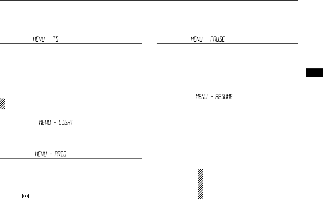
Tuning step (Default: 25.0)
When you rotate [DIAL] in the VFO mode, the frequency
changes in the selected tuning step.
The selected tuning step is also used for a VFO mode scan.
Tuning steps (kHz):
5, 6.25, 8.33*, 10, 12.5, 15, 20, 25, 30, 50 and Auto*
*Appears only when the AIR band is selected.
In the AIR band, you can select only “8.33k”, “25k” and
“Auto.”
LCD Backlight (Default: 4)
Set the backlight brightness level to between 1 (Dark) and 4
(Bright).
Priority scan (Default: OFF)
Starts or stops the Priority scan.
•OFF: StopsthePriorityscan.
•ON: StartsthePriorityscan.
•BELL: StartsthePriorityscan.
When a signal is received on the priority channel, the
“” icon is displayed on the screen.
Pause Timer (Default: 10SEC)
Select the Scan Pause time.
•2SEC to 20SEC: When a signal is received, the scan paus-
es for 2 to 20 seconds (set in 2 second
steps).
•HOLD: The scan pauses on a received signal until
the signal disappears.
Resume Timer (Default: 2SEC)
Select the Scan Resume time.
When a received signal disappears, the scan resumes ac-
cording to this setting.
•0SEC: The scan resumes immediately after the
signal disappears.
•1SECto5SEC: Thescanresumes1to5secondsafterthe
signal disappears.
•HOLD: The scan remains paused for the“Pause
Timer” setting, even if the signal disap-
pears.
NOTE:
• Rotate [DIAL] to resume the scan.
•
The Resume Timer must be set shorter
than the Pause Timer, otherwise this
timer does not work properly.
11
2MENU MODE
New2001 New2001
New2001
Weather alert (Default: OFF)
(Appears only for the U.S.A. version.)
Turn the Weather Alert function ON or OFF.
A NOAA (National Oceanographic and Atmospheric Admin-
istration) broadcast station transmits a weather alert tone be-
fore any important weather information.
This function detects the weather alert tone on weather chan-
nels.
•OFF:ThefunctionisOFF.
•ON: Monitorstheselected weather channelevery 5 sec-
onds.
Operating mode (Default: FM)
The transceiver has a total of five operating modes; FM, FM-
N, AM and AM-N.
Operating modes are determined by the modulation of the
radio signals.
•Inthe144and430MHzbands,selectFMorFM-N.
•IntheAIRband(118.000MHzto136.99166MHz),select
AM or AM-N.
While in the FM-N mode, the TX modulation is automati-
cally set to narrow (approximately ±2.5 kHz)
Menu items (Continued) ■
Home CH ,
When you set the often-used frequency as the Home chan-
nel in the transceiver’s VFO or Memory mode, that frequency
is selected by pushing [HOME CALL] of the supplied micro-
phone in each mode.
•SET.FREQ:SettheselectedVFOfrequency astheHome
channel.
•SETMR: SettheselectedMemorychannelfrequencyas
the Home channel.
EX Menu mode
Enters the EX Menu mode.
See pages ?? to ?? for the items that you can set in the EX
Menu mode.
See the Icom website for details of the EX Menu mode items.
New2001
1
3
BASIC OPERATION
New2001
3
BASIC OPERATION
Selecting the MAIN band ■
Push [MAIN BAND] ➥S on the desired frequency band to
set it as the MAIN band.
•“MAIN”appearsontheMAINband.
•YoucantransmitononlytheMAINband.
Selecting the Mode ■
•Youcanselectoneithertheleftorrightband,regard-
less of the MAIN band.
VFO mode D
The VFO mode is used to set the operating frequency.
Push [V/MHz SCAN] ➥S.
•SelectstheVFOmode.
•Rotate[DIAL]S to select an operating frequency.
Memory mode D
The Memory mode is used to operate on Memory channels.
Push [MR CALL] ➥S.
•SelectstheMemorymode.
•Rotate[DIAL]S to select a Memory channel.
Call channel mode D
The Call channel mode is used to operate on the Call chan-
nels.
Hold down [MR CALL] ➥S for 1 second.
•SelectstheCallchannelmode.
•Rotating[DIAL]S selects a Call channel.
Weather channel mode D
(Selectable in only the U.S.A. version transceivers)
The Weather channel mode is used to hear weather broad-
casts from the NOAA (National Oceanographic and Atmo-
spheric Administration).
In the Memory mode, push [MR CALL] ➥S.
•SelectstheWeatherchannelmode.
•Rotating[DIAL]S selects a Weather channel.
Side Side
Display
Center
The C, S or D in the
instructions indicate the
part of the controller.
C: Center
S: Side
D: Display
2
3BASIC OPERATION
New2001 New2001
New2001
Setting a frequency ■
Selecting the 1 MHz tuning D
•Youcanselectoneithertheleftorrightband,regard-
less of the MAIN band setting.
•ThissectiondescribestheMAINbandoperation.
Push [V/MHz SCAN] qS.
•SelectstheVFOmode.
Push [V/MHz SCAN] wS.
•Selectsthe1MHztuning.
Rotate [DIAL] eS.
•Thefrequencychangesin1MHzsteps.
Push [V/MHz SCAN] rS.
•Cancelsthe1MHztuning.
Selecting the operating band ■
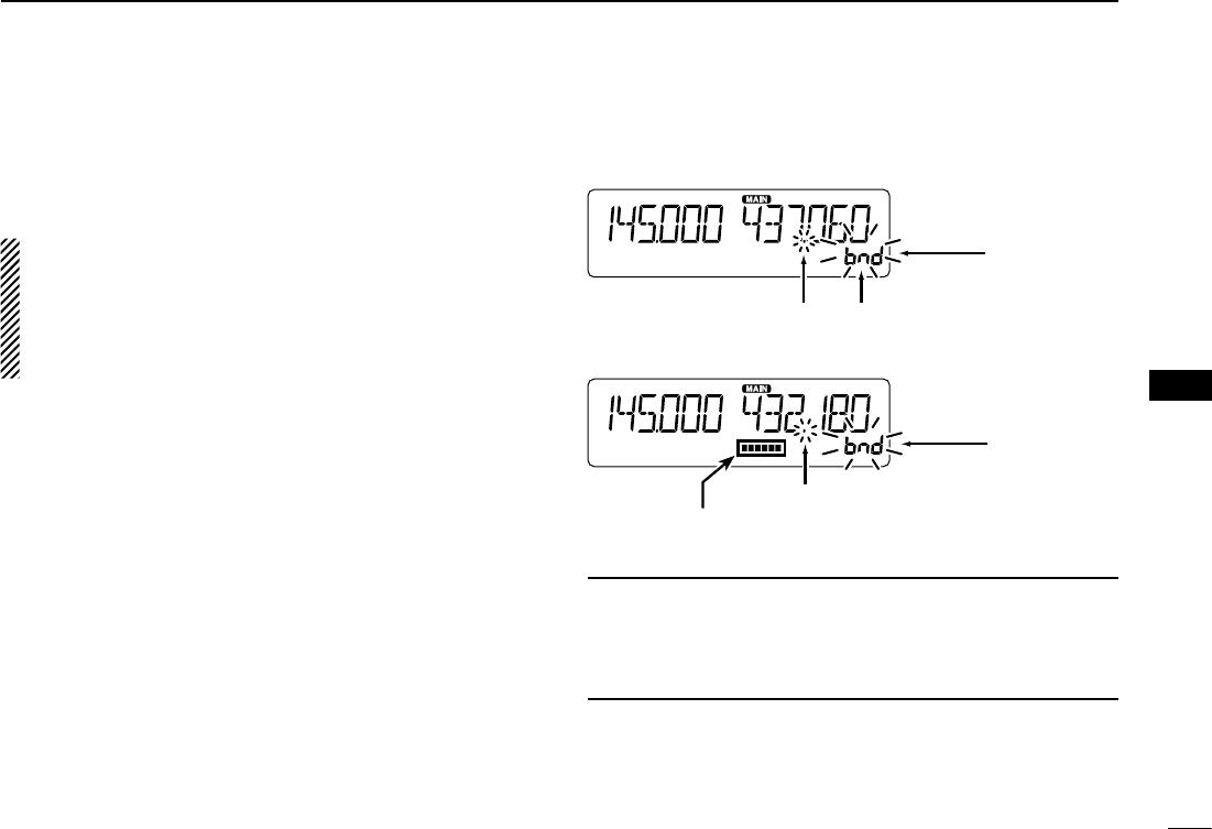
The transceiver can receive the AIR, 144 MHz or 430 MHz
bands.
You can transmit on only the 144 MHz and 430 MHz bands.
Operating band Frequency range
AIR 118.000 MHz to 136.99166 MHz
144 MHz 137.000 MHz to 174.000 MHz
430 MHz 375.000 MHz to 550.000 MHz
The ranges may differ, depending on the transceiver’s version.
•Youcanselectoneithertheleftorrightband,regard-
less of the MAIN band setting.
•ThissectiondescribestheMAINbandoperation.
Push [V/MHz SCAN] qS.
•SelectstheVFOmode.
Hold down [MAIN BAND] wS for 1 second.
•EnterstheOperatingbandselectmode.
Rotate [DIAL] eS to select the desired operating band.
Push [MAIN BAND] rS.
•Returnstothestand-bymode.
Side Side
Display
Center
The C, S or D in the
instructions indicate the
part of the controller.
C: Center
S: Side
D: Display

New2001
3
3
BASIC OPERATION
New2001
3
BASIC OPERATION
Selecting a tuning step D
Rotating [DIAL]S changes the frequency in the selected tun-
ing steps.
The VFO scan uses this step to search for a signal. (p. ??)
Push [V/MHz SCAN] qS.
•SelectstheVFOmode.
Push [MAIN BAND] wS on the band that the tuning step is
set to.
Push [MENU e]C.
•EnterstheMENUmode.
r Rotate [DIAL]S to select “TS” (Tuning step).
Push [ tï]D.
•Goestothenexttreelevel.
Rotate [DIAL] yS to select the desired value.
Selectable values:
5 kHz, 6.25 kHz, 8.33 kHz*, 10 kHz, 12.5 kHz, 15 kHz,
20 kHz, 25 kHz, 30 kHz, 50 kHz or Auto*.
*Appears only when the AIR band is selected.
Push [ uï]D.
•Setstheselectedvalue,andgoesbacktotheprevioustreelevel.
Push [MAIN BAND] iS.
•ExitstheMENUmode.
Setting audio volume and ■
squelch level
•Youcansetoneithertheleftorrightband,regardlessof
the MAIN band setting.
Rotate [VOL] qS to adjust the audio level.
•You can change the beep level in the“BEEPLV” (Beep Level)
item of the MENU mode. (p. ??)
(MENU-EXMENU > EXMEN-SOUNDS > SOUND-BEEPLV)
Rotate [SQL] wS until the noise and the “BUSY” icon just
disappear.
•Rotating [SQL]S clockwise makes the squelch tight. Tight
squelch is for strong signals.
•When rotating [SQL]S clockwise beyond the center position,
[SQL]S can be used as ‘S-meter Squelch’ or ‘Attenuator.’ Select
the [SQL]S option in the MENU mode. (p. ??)
Lock function ■
You can use the Lock function to prevent accidental frequen-
cy changes and unnecessary function access.
Hold down [MENU ➥]C for 1 second.
•“ ” appears.
•Holddown[MENU ]C again to cancel the function.
•You can still use [ ], [MONI DUP]C, [PTT], [MAIN BAND]S
(only the MAIN band selection), [MENU ]S (only the Lock
function canceling), [SQL]S, and [VOL]S while the Lock func-
tion is ON.
4
3BASIC OPERATION
New2001 New2001
New2001
Selecting the operating mode ■
The transceiver has a total of four operating modes, AM, AM-
N, FM and FM-N.
The FM mode is set as a default.
•Youcanselectoneithertheleftorrightband,regard-
less of the MAIN band setting.
•ThesettingisfortheMAINband.
Push [MAIN BAND] qS of the band that the operating mode
is set to.
Push [MENU w]C.
•EnterstheMENUmode.
e Rotate [DIAL]S to select “MENU-MODE” (Operating mode).
Push [ rï]D.
•Goestothenexttreelevel.
Rotate [DIAL] tS to select the desired operating mode.
Selectable options:
In the 144 or 430 MHz band: FM or FM-N
In the AIR band: AM or AM-N
•WhileintheFM-Nmode,theTXmodulationisautomaticallyset
to approximately ±2.5 kHz.
Push [ yï]D.
•Setstheselectedoption,andgoesbacktotheprevioustreelevel.
Push [MAIN BAND] uS.
•ExitstheMENUmode.
Transmitting ■
Before transmitting, monitor the operating frequency
to see if other stations are on the frequency.
CAUTION: Transmitting without an antenna may damage
the transceiver.
•You can transmit on only the 144 MHz and 430 MHz
bands,andontheMAINband.
•Thetransmitoutputpowerlevelcanbeindividuallyset
fortheleftandrightbands,whenitisselectedasthe
MAIN band.
Push [LOW DTMF] qC to select the output power level.
Selectable levels: Low, Mid, and High
•Lower output power during short-range communications may
reduce the possibility of interference to other stations, and will
conserve battery power.
•Thepowericondisappearswhenhighpowerisselected.
Hold down [PTT] to transmit, and speak at your normal w
voice level.
•TheS/RFmeterdisplaystheoutputpowerlevel.
Release [PTT] to receive. e
New2001
5
3
BASIC OPERATION
New2001
3
BASIC OPERATION
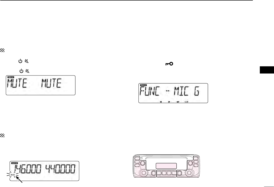
Audio mute function ■
This function temporarily mutes the audio without disturbing
the volume setting.
This function is for both the MAIN and SUB bands.
Push [ ➥]( ) to mute audio signals.
•“MUTE”appearontheleftandrightbands.
•Push[ ]( ) (or any other key) to cancel the function.
Setting the microphone gain level ■
Set the microphone gain level in the MENU mode.
•Youcansetoneithertheleftorrightband,regardlessof
the MAIN band setting.
•ThissectiondescribestheMAINbandoperation.
Push [MENU q]C.
•EnterstheMENUmode.
w Rotate [DIAL]S to select “MIC G” (
MIC Gain
).
(MENU-EXMENU > EXMEN-FUNC > FUNC-MIC G)
Push [ eï]D.
•Goestothenexttreelevel.
Rotate [DIAL] rS to adjust the microphone gain level.
•Set higher values to make the microphone more sensitive to
your voice.
Push [ tï]D.
•Setstheselectedvalue,andgoesbacktotheprevioustreelevel.
Push [MAIN BAND] yS.
•ExitstheMENUmode.
Monitor function ■
This function is used to listen to weak signals without disturb-
ing the squelch setting.
This function is for the MAIN band.
Push [MONI DUP] ➥
C
to open the squelch.
•“BUSY”blinkswhenthesquelchisopen.
•Push[MONIDUP]
C
again to cancel the function.
Blinks
While monitoring
Side Side
Display
Center
The C, S or D in the
instructions indicate the
part of the controller.
C: Center
S: Side
D: Display

1
New2001New2001
MEMORY OPERATION
4
New2001
General description ■
The transceiver has a total of 1000 Memory channels (100
channels in each of 10 memory banks, A to J) and two Call
channels (C0/C1) for the 144 and 430 MHz bands.
The Memory mode is useful to quickly select often-used fre-
quencies.
Memory Channels Descriptions
000–999
Total of 1000 regular Memory chan-
nels
Memory channels are selectable on
either the left or right band, and us-
able for any operating band.
C0/C1
Two Call channels
(C0: 144 MHz, C1: 430 MHz)
Instantly recalls a specified frequen-
cy.
Memory channel content D
The following information can be entered into the Memory
channels:
•Operatingfrequency
•Duplexdirection(DUP+orDUP–)andfrequencyoffset
•Memoryname
•Scanskipsetting
•Tuningstep
•Operatingmode
•Subaudible tone encoder, tone squelch or DTCS squelch
ON/OFF
•Subaudible tone frequency, tone squelch frequency or
DTCS code with polarity
•Memorybank
The number of the Memory channel D
New2001
2
4
MEMORY OPERATION
New2001
4
MEMORY OPERATION
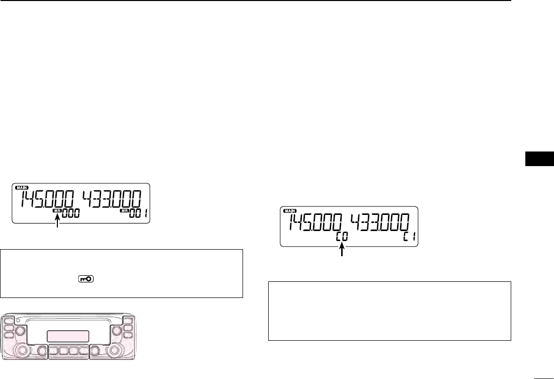
Selecting a Memory channel D
You can select the Memory channels by rotating [DIAL]S in
the Memory mode.
•Selectableoneithertheleftorrightband.
Push [MR CALL] qS.
•SelectstheMemorymode.
Rotate [DIAL] wS to select a Memory channel.
•Blankchannelsarenotselected.
Appears
Selecting a Call channel D
You can select the
Call channels (C0/C1) by rotating [DIAL]S
in the Call channel mode.
Factory default frequencies and operating modes are entered
into the Call channels.
Change these to suit your operating needs.
•Selectableoneithertheleftorrightband.
Hold down [MR CALL] qS for 1 second.
•SelectstheCallchannelmode.
Rotate [DIAL] wS to select a Call channel.
Displays the Call channel number
For your reference:
Using the HM-207 microphone (p. ??)
Push [VFO/MR q] to select the Memory mode.
Enter the Memory channel number, and then push [ENT]. w
Side Side
Display
Center
The C, S or D in the
instructions indicate the
part of the controller.
C: Center
S: Side
D: Display
For your reference:
Using the HM-207 microphone (p. ??)
Hold down [HOME CALL] for 1 second to select the Call q
channel mode.
Push [ w∫] or [√] to select a Call channel.
Selecting a Memory or Call channel ■
3
4MEMORY OPERATION
New2001 New2001
New2001
Writing into a Memory or Call channel ■
After setting a frequency in the VFO mode, you can write it
into your desired channel or an automatically selected blank
channel.
Memory channels 002 to 999 are blank as the default.
Memory channels are selectable on either the left or right
band, and usable for any operating band.
•Youcanwriteoneithertheleftorrightband,regardless
of the MAIN band setting.
•ThissectiondescribestheMAINbandoperation.
Writing into the selected channel D
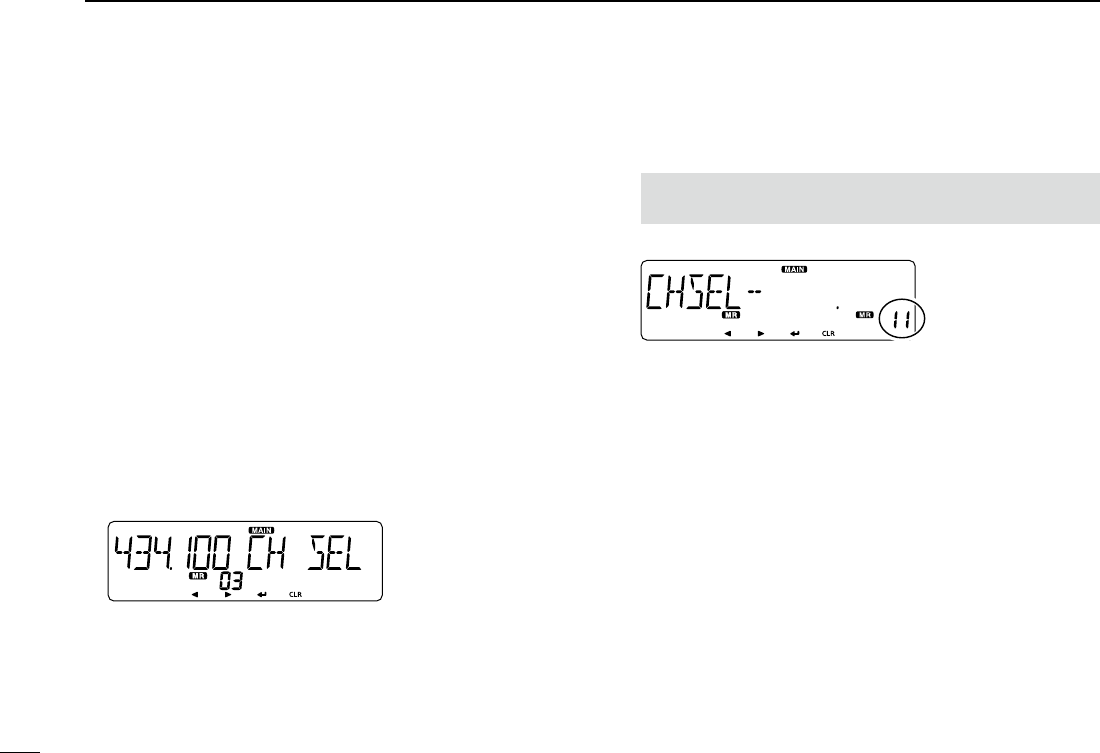
Example: Writing 434.100 MHz into Memory channel “11.”
Push [V/MHz SCAN] qS.
•SelectstheVFOmode.
Set the operating frequency to 434.100 MHz. w
Push [MW] eC to display the Memory Entry screen.
Push [ rï]D.
•DisplaystheChannelSelectscreen.
•Push[Ω]D to go back to the previous tree level.
Rotate [DIAL] tS to select channel “11.”
NOTE: If you select a pre-entered channel, the previous
channel content will be overwritten.
•YoucanalsoselectCallchannels.
Select
Push [ yï]D.
Rotate [DIAL] uS to select “WRITE.”
Push [ iï]D.
•Displays“WRITE?.”
Rotate [DIAL] oS to select “YES.”
!0 Push [ï]D.
•Beepssound.
•Writesintotheselectedchannel,andreturnstotheVFOmode.
Writing into a blank channel D
Example: Writing 434.100 MHz into a blank channel.
Push [V/MHz SCAN] qS.
•SelectstheVFOmode.
Set the operating frequency to 434.100 MHz. w
Hold down [MW] eC for 1 second.
•Automaticallywritesintoablank,andreturnstotheVFOmode.
New2001
4
4
MEMORY OPERATION
New2001
4
MEMORY OPERATION
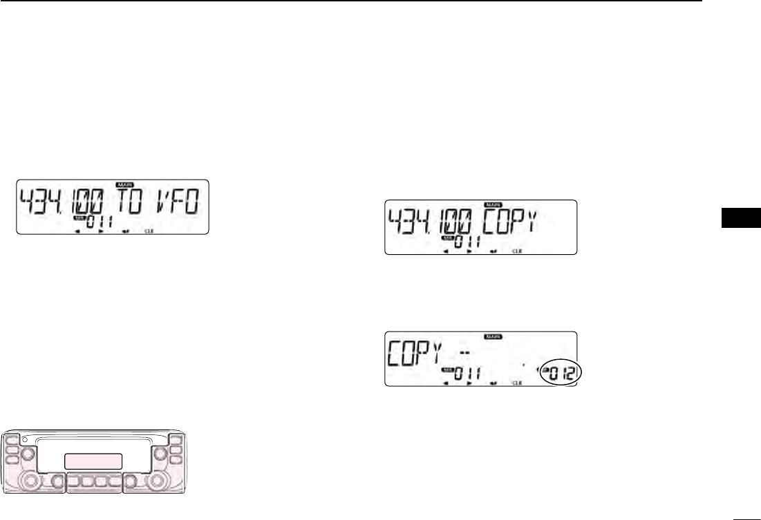
Copying Memory content to the VFO D
This is convenient when you want to change the frequency
beginning near the Memory or Call channel frequency.
Select a desired Memory channel to be copied. q(p. ??)
Push [MW] wC to display the Memory Edit screen.
Rotate [DIAL] eS to select “TO VFO.”
Push [ rï]D.
•Beepssound.
•WritestheselectedMemorycontenttotheVFO,andreturnsto
the VFO mode.
Copying Memory content to another DMemory channel
You can copy the memory content to another Memory chan-
nel.
Select the desired Memory channel to be copied. q(p. ??)
Push [MW] wC to display the Memory Edit screen.
Rotate [DIAL] eS to select “COPY.”
Push [ rï]D.
Rotate [DIAL] tS to select a target channel.
•Ifyouselectapre-enteredchannel,thepreviouschannelcon-
tent is displayed.
Select
Push [ yï]D.
•Beepssound.
•Copiestothedestinationchannel.
•Whenyouselectapre-enteredchannel,“OVERW?”isdisplayed.
Rotate [DIAL]S to select “YES,” and then push [ï]D to over-
write it.
Side Side
Display
Center
The C, S or D in the
instructions indicate the
part of the controller.
C: Center
S: Side
D: Display

5
4MEMORY OPERATION
New2001 New2001
New2001
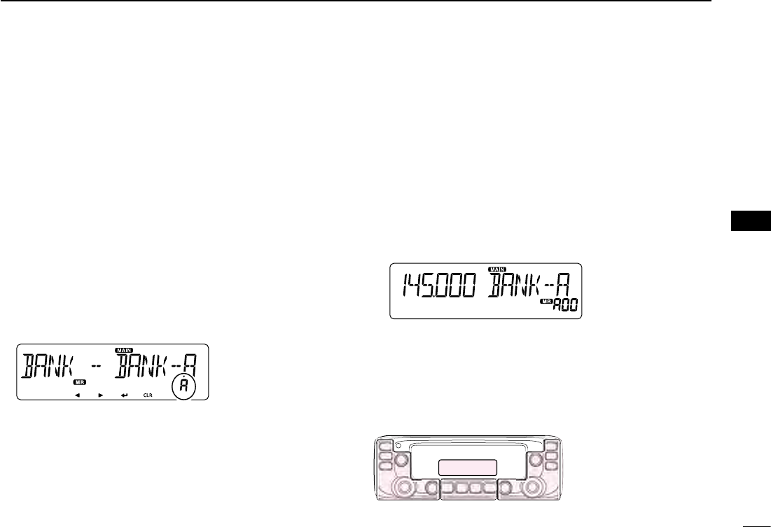
Setting a Memory bank ■
The transceiver has a total of 10 banks (A to J).
You can assign regular Memory channels 0 to 999 to any
desired bank for easy memory management.
You can assign up to 100 channels to a bank.
It is convenient that you categorize the Memory bank, accord-
ing to the Memory channel category or your purpose.
You can use the Memory bank scan to scan the memory
channels in the selected bank. (p. ??)
•YoucansettheMemorybanksoneithertheleftorright
band,regardlessoftheMAINbandsetting.
•ThissectiondescribestheMAINbandoperation.
NOTE: The memory banks are only used to hold memory
channels. Thus if the original memory channel content has
been changed, the memory bank content is also changed
at the same time.
For your reference: To cancel your entry
After entering, push [ qΩ]D or [CLR]D.
•Displaysthe“CANCEL?.”
w
Rotate [DIAL]S to select “YES.”
Push [ eï]D.
Assigning a memory channel to a memory bank D
Select the Memory channel to be assigned to a bank. q(p.
??)
Push [MW] wC to display the Memory Edit screen.
Rotate [DIAL] eS to select “EDIT.”
Push [ rï]D.
Rotate [DIAL] tS to select “BANK.”
Push [ yï]D.
Rotate [DIAL] uS to select a desired bank group, “A” to “J.”
Select
Push [ iï]D.
Rotate [DIAL] oS to select “WRITE.”
!0 Push [ï]D.
•Displaysthe“OVERW?.”
!1 Rotate [DIAL]S to select “YES.”
!2 Push [ï]D.
•Beepssound.
•Assignstheselectedmemorychanneltothebank.
New2001
6
4
MEMORY OPERATION
New2001
4
MEMORY OPERATION
Directly entering into a memory bank D
You can also enter the memory content directly into a memo-
ry bank channel. This way is a short cut to creating a memory
channel, and then assigning it to a bank.
In that case, the transceiver automatically selects the lowest
blank memory channel, to enter content into.
Example: Writing 434.100 MHz into Bank group “A.”
Push [V/MHz SCAN] qS.
•SelectstheVFOmode.
Set the operating frequency to 434.100 MHz. w
Push [MW] eC to display the Memory Entry screen.
Rotate [DIAL] rS to select “BANK.”
Push [ tï]D.
Rotate [DIAL] yS to select a Bank group “A.”
Select
Push [ uï]D.
Rotate [DIAL] iS to select “WRITE.”
Push [ oï]D.
•Displaysthe“WRITE?.”
!0 Rotate [DIAL]S to select “YES.”
!1 Push [ï]D.
•Beepssound.
•Writesthememorycontenttothebankchannel.
Selecting the Memory bank mode D
When you select the Memory bank mode, rotating [DIAL]S se-
lects only the bank channels assigned to the selected bank.
Push [MR CALL] qS.
•SelectstheMemorymode.
Hold down [MAIN BAND] wS for 1 second.
Rotate [DIAL] eS to select the desired Bank group.
•OnlyBankgroupsthathavememorychannelisassigned toit
are displayed.
Push [MAIN BAND] rS.
•SelectstheMemorybankmode.
Rotate [DIAL] tS to select a desired Bank channel.
•Onlyassignedbankchannelsaredisplayed.
•To return to the Memory channels display, select a Memory
channel in step e.
Side Side
Display
Center
The C, S or D in the
instructions indicate the
part of the controller.
C: Center
S: Side
D: Display
7
4MEMORY OPERATION
New2001 New2001
New2001
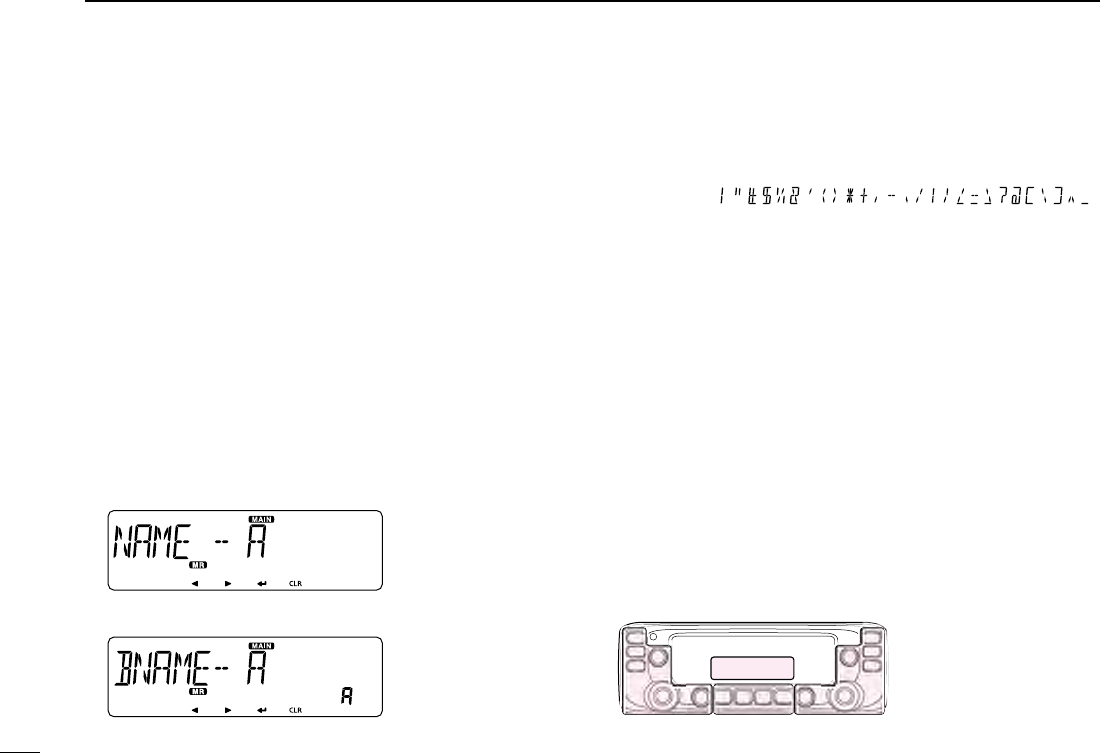
Entering a Memory or Bank name ■
You can enter an alphanumeric name for each Memory chan-
nel, Call channel, and Bank.
Names can up to 6 characters.
•Youcanenteroneithertheleftorrightband,regardless
of the MAIN band setting.
Select a Memory channel to enter a name. q
•ToenteraBankname,selectaBankgroup.
Push [MW] wC to display the Memory Edit screen.
Rotate [DIAL] eS to select “EDIT.”
Push [ rï]D.
Rotate [DIAL] tS to select “NAME.”
•ToenteraBankname,select“BNAME.”
Push [ yï]D.
Rotate [DIAL] uS to select a desired character or symbol.
(Example: A)
When entering a Memory name
When entering a Bank name
•Selectablecharactersorsymbols:
A to Z, 0 to 9, and
Symbols ( )
•Push[CLR]D to delete the selected character, symbol or num-
ber.
•Whennocharacterorsymbolisselected,push[≈](D) to enter
a space.
Push [ iΩ] to move the cursor backwards, or push [≈] to
move the cursor forwards.
Repeat steps o u and i to enter a name of up to 6 charac-
ters, including spaces.
!0 After entering, push [ï]D.
!1 Rotate [DIAL]S to select “WRITE.”
!2 Push [ï]D.
•Displays“OVERW?.”
!3 Rotate [DIAL]S to select “YES.”
!4 Push [ï]D.
•Beepssound.
•Writestheenterednametothechannel.
Side Side
Display
Center
The C, S or D in the
instructions indicate the
part of the controller.
C: Center
S: Side
D: Display

New2001
8
4
MEMORY OPERATION
New2001
4
MEMORY OPERATION
Clearing a Memory channel ■
Entered memory content can be cleared (erased), if desired.
NOTE: Once you clear a memory content, it cannot be re-
covered.
•Youcanclearachanneloneithertheleftorrightband,
regardless of the MAIN band setting.
Push [MR CALL] qS.
•SelectstheMemorymode.
•WhenyouclearaCallchannel,holddown [MRCALL]S for 1
second to select the Call channel mode.
Push [MW] wC to display the Memory Edit screen.
Rotate [DIAL] eS to select “CLEAR.”
Push [ rï]D.
Rotate [DIAL] tS to select a desired channel to be cleared.
Push [ yï]D.
•Displays“CLEAR?.”
Select
Rotate [DIAL] uS to select “YES.”
Push [ iï]D.
•Beepssound.
•Clearsthememorycontent.
1
New2001New2001
SCAN OPERATION
5
New2001
About the scan function ■
VFO scan D
•ALL (Full scan) p. ??
Repeatedly scans the entire band.
118 MHz 550 MHz
Scan P SKIP
P SKIP
Jump
•BAND (Selected band scan) p. ??
Scans all frequencies over the entire selected band.
Band edge Band edge
Scan P SKIP
P SKIP
Jump
•PROG 0–24 (Program scan) p. ??
Scans the program scan edge ranges.
Band
edge Lower
freq. Higher
freq. Band
edge
Scan edges
ScanJump
Jump
•P-LINK0–9 (Program link scan) p. ??
Sequentially scans the program scan edge ranges which
are set to link in the “P-LINK” (Program Link) item of the
EXMENU. (p. ??)
For your reference: The frequencies that are set as
“PSKIP” are not scanned. (p. ??)
NOTE: At least one program scan edge range must be
programmed to start a program scan. (p. ??)
Memory scan D
•ALL (Memory full scan) p. ??
Scans all Memory channels.
•BAND (Selected band memory scan) p. ??
Scans all Memory channels on the same frequency band as
the selected channel.
•MODE (Mode memory scan) p. ??
Scans Memory channels which are programmed with the
same receiving mode as the currently selected mode.
Memory bank scan D
•ALL (Full bank scan) p. ??
Scans all banks.
•BANK-LINK (Bank link scan) p. ??
Sequentially scans the banks which are set to link in the
“BANK LINK” item of the MENU mode.
•BANK-A–Z (Bank scan) p. ??
Scans the Memory channels in the selected bank.
For your reference: The frequencies that are set as
“PSKIP” or “SKIP” are not scanned. (p. ??)
NOTE: Two or more memory channels must be pro-
grammed to start a memory scan.

New2001
2
5
SCAN OPERATION
New2001
5
SCAN OPERATION
[Duplex (DUP) scan]
The Duplex scan searches for both TX and RX frequencies
which are used in duplex operation. (p. ??)
•The “DUP–” or “DUP+” icon is displayed in the duplex
mode.
•Aduplexscanwillnotstartwhenthefrequencyoffsetis
set to “0.000 MHz.”
[Tone scan]
The tone scan searches for tone frequencies or DTCS codes
that are used by stations using the Tone Squelch function.
•Youcanusea tonescanin anymode:VFO, Memoryor
Call channel.
•Duringatonescan,rotate[DIAL]S to switch scan direc-
tion.
Refer to “Tone Squelch function” or “DTCS code Squelch
function” for details. (pp. ??, ??)
[DIAL] operation during a scan D
•Ifdesired,rotate[DIAL]S to switch the scanning direction
during a scan.
•When the scan is paused, rotate [DIAL]S to resume the
scan.
Tuning step for a VFO scan D
The selected tuning step is applied to the scan.
For a program scan or program link scan, set the tuning step
in the program scan edge ranges.
Skip function D
The skip function speeds up scanning by not scanning those
frequencies set as skip channels. (pp. ??, ??)
For your reference:
When the “P-SKIP” (Program Skip) item is set to OFF, the
Scan Skip function cannot be used. (p. ??)
3
5SCAN OPERATION
New2001 New2001
New2001
About the scan function (Continued) ■
Receive mode during a scan D
•Theselectedmodeisusedbythescan.
•Duringamemoryorbankscan,thechannel’smodeisused
by the scan.
Blinks
Scanning in the FM mode
Displays the scan type
Blinks
When a signal is received D
When a signal is received, the scan pauses for approximately
10 seconds (default), then resumes.
The scan resumes approximately 2 seconds (default) after
the signal disappears.
To manually resume the scan, rotate [DIAL]S.
•Thesesettingscanbechangedinthe“PAUSE”(PauseTim-
er) item or “RESUME” (Resume Timer) item of the MENU
mode. (pp. ??, ??)
Scan name D
A desired name can be assigned to each Program scan edge
or Scan Link. (p. ??)
By selecting the scan name, the scanning frequency range
will be set.
Entering scan edges ■
You can enter the higher and lower frequency edges to the
program scan edge ranges for programmed scans.
Each program scan edge range has its own tuning step and
the receive mode.
The default setting is differ, depending on the transceiver’s
version.
You can enter a total of up to 25 program scan edge ranges.
Scan Stop Beep function D
The Scan Stop Beep function sounds a beep when a signal
is received.
The function can be turned ON or OFF in the “STOP B” (Scan
Stop Beep) item of the EXMENU. (p. ??)
Side Side
Display
Center
The C, S or D in the
instructions indicate the
part of the controller.
C: Center
S: Side
D: Display
New2001
4
5
SCAN OPERATION
New2001
5
SCAN OPERATION
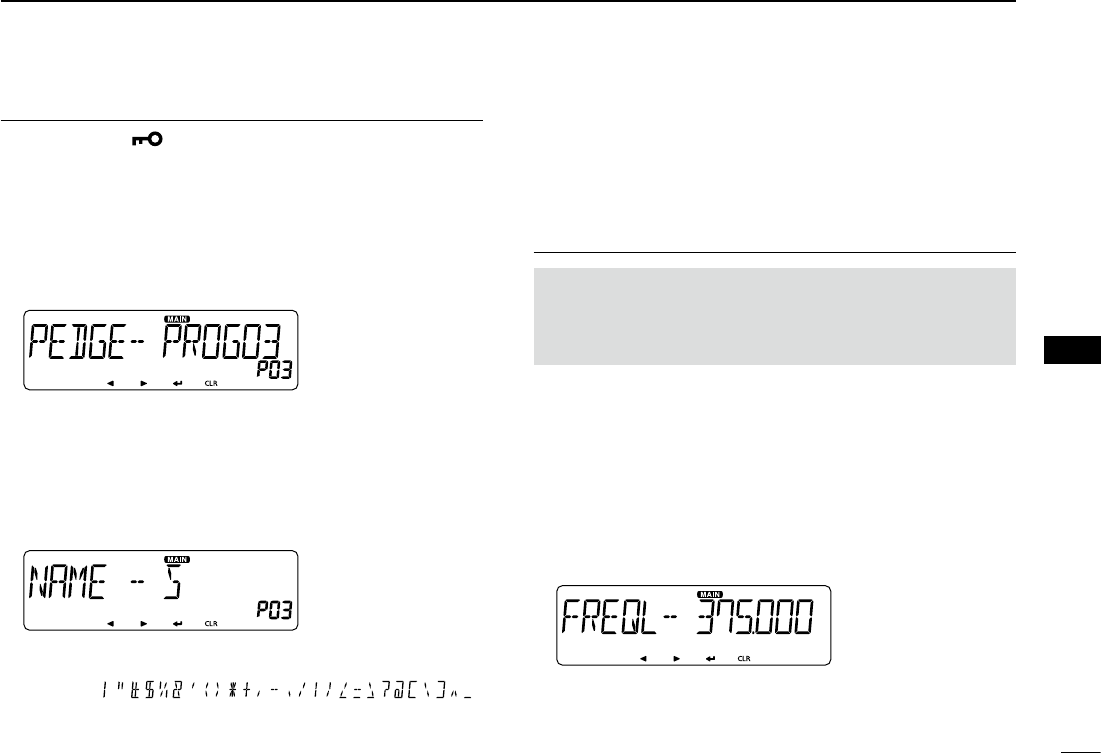
Entering a scan name1.
Push [MENU q]C.
•EnterstheMENUmode.
w Rotate [DIAL]S to select “P-EDGE” (Program Scan Edge).
(MENU-EXMENU > EXMEN-SCAN > SCAN-P-EDGE)
Push [ eï]D.
•Goestothenexttreelevel.
Rotate [DIAL] rS to select
a desired scan edge channel.
(Example: 3)
Push [ tï]D.
•Goestothenexttreelevel.
Rotate [DIAL] yS to select
“NAME.”
Push [ uï]D to display the Scan name entry screen.
Rotate [DIAL] iS to select a desired character or symbol.
(Example: S)
Scan name entry
screen
•Selectablecharactersorsymbols:
A to Z, 0 to 9, and
Symbols ( )
•Push[CLR]D to delete the selected character, symbol or number.
•Whennocharacterorsymbolisselected,push[≈](D) to enter
a space.
Push [ oΩ] to move the cursor backwards, or push [≈] to
move the cursor forwards.
!0 Repeat steps u and i to enter a name of up to 6 charac-
ters, including spaces.
!1 After entering, push [ï]D.
Entering a scan frequency2.
NOTE: You must enter different frequencies in “FREQ L” and
“FREQ H,” to specify a scanning frequency range.
If identical frequencies are entered to “FREQ L” and “FREQ
H,” the Program scan will not work.
!2 Rotate [DIAL]S to select “FREQ L.”
!3 Push [ï]D to display the Lower edge frequency setting
screen.
!4 Rotate [DIAL]S to select a desired number.
!5 Push [Ω] to move the cursor backwards, or push [≈] to
move the cursor forwards.
!6 Repeat steps !4 and !5 to enter a lower edge frequency.
(Example: 375.000)
!7 After entering, push [ï]D.
Lower edge frequency
setting screen
Continued on the next page ☞

5
5SCAN OPERATION
New2001 New2001
New2001
!8 Rotate [DIAL]S to select “FREQ H,” and enter a higher
edge frequency with the same way as steps !3 and !5.
!9 After entering, push [ï]D.
Setting a tuning step3.
NOTE: If the frequencies entered in “FREQ L” and “FREQ
H” are on a different band, the Tuning step setting screen
does not appear. In this case, the VFO mode’s turning step
for each band is used during a scan.
@0 Rotate [DIAL]S to select “TS.”
@1 Push [ï]D to display the Tuning step setting screen.
@2 Rotate [DIAL]S to select a desired tuning step to be used
while program scanning.
Selectable value:
5 kHz, 6.25 kHz, 8.33 kHz*, 10 kHz, 12.5 kHz, 15 kHz,
20 kHz, 25 kHz, 30 kHz, 50 kHz or Auto*.
*Appears only when the AIR band is selected.
@3 After selecting, push [ï]D.
Entering scan edges (Continued) ■Setting a operating mode4.
NOTE:
• If the frequencies entered in Freq Low and Freq High are
on a different band, the Operating mode setting screen
does not appear. In this case, the VFO mode’s operating
mode for each band is used during a scan.
• When the entered frequencies are in the VHF AIR band,
the setting is restricted.
@4 Rotate [DIAL]S to select “MODE.”
@5 Push [ï]D to display the Operating mode setting screen.
@6 Rotate [DIAL]S to select a desired operating mode.
@7 After selecting, push [ï]D.
Setting a operating mode5.
@8 Rotate [DIAL]S to select “WRITE.”
@9 Push [ï]D.
•Displays“WRITE?.”
#0 Rotate [DIAL]S to select “YES.”
#1 Push [ï]D.
•Beepssound.
•Entersthescanedges,andreturnstotheScanedgechannel
select screen.
Side Side
Display
Center
The C, S or D in the
instructions indicate the
part of the controller.
C: Center
S: Side
D: Display
New2001
6
5
SCAN OPERATION
New2001
5
SCAN OPERATION
VFO mode scan ■
There are 6 scan types: Full scan, Band scan, Program scan,
Program link scan, Duplex scan and Tone scan.
NOTE:
•The frequencies that are set as skip channels“PSKIP”
are skipped during a scan.
•
When the “P-SKIP” (Program Skip) item in the EXMENU
is set to OFF, the frequencies that are set as skip channels
“PSKIP” are not skipped during a scan.
VFO mode scan D
Push [V/MHz SCAN] qS.
•SelectstheVFOmode.
Hold down [V/MHz SCAN] wS for 1 second.
•Displaysthescantypesettingscreen.
Rotate [DIAL] eS to select a desired scan type.
•ALL: Fullscan
•BAND: Bandscan
•P-LINK0–9:Programlinkscan
•P00–24: Programscan
•DUP: Duplexscan(p. ??)
( Appears only when duplex is set.)
•TONE: Tonescan
(For tone squelch scanning)
Push [V/MHz SCAN] rS to start the scan.
To cancel the scan, push [V/MHz SCAN] tS.
While scanning
Displays the scan type
Blinks
Blinks
When receiving a signal
The S-meter shows the received signal strength.
Blinks
Blinks
When a scan name is assigned.
When a scan name is assigned, the scan name is displayed
on the scan type setting screen. (Step e on this page)
See page ?? to enter the scan name.
When a program link name is assigned.
When a program link name is assigned, the program link
name is displayed on the scan type setting screen. (Step e
on this page)
See page ?? to enter the program link name.
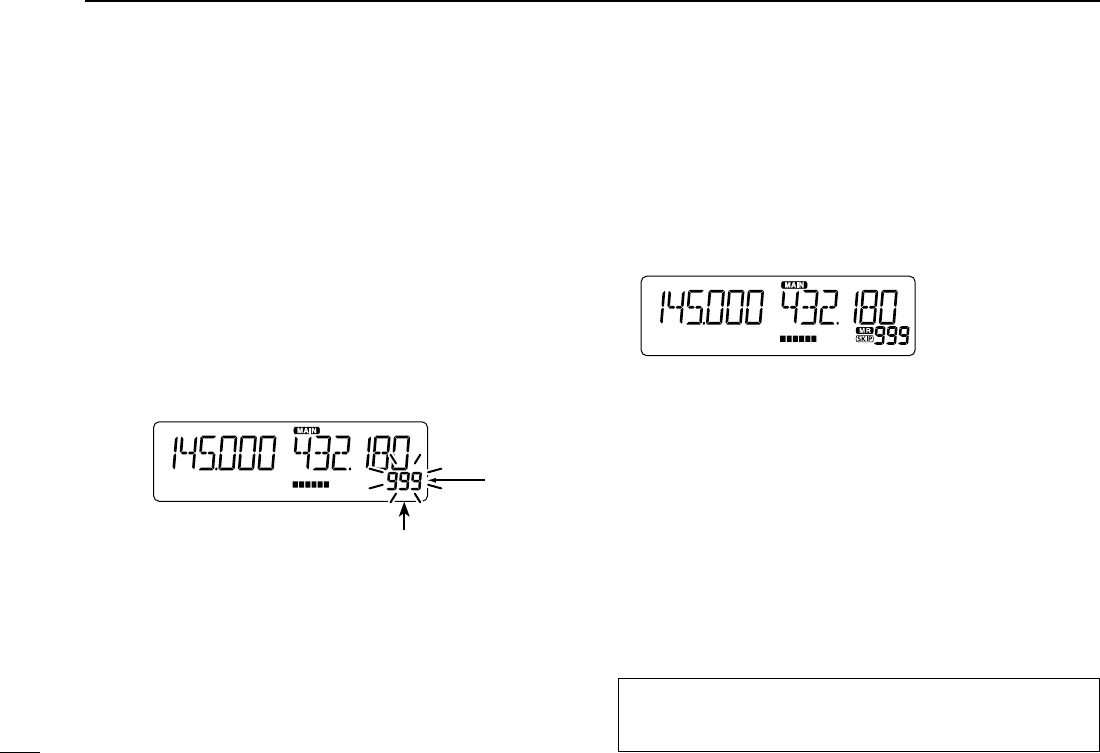
7
5SCAN OPERATION
New2001 New2001
New2001
Setting the skip frequencies D
The frequencies set as “PSKIP” skip channels are not
scanned.
Start the VFO scan. q(p. ??)
•Whenasignalisreceived,thescanpauses.
While the scan is paused, and if you want to skip the fre- w
quency, hold down [MW]C for 1 second (until 3 beeps
sound).
•Whena signalis receivedduring thescan, thetransceiverat-
tempts to enter the frequency as a skip channel into empty
memory channel 999.
Skip frequency is entered
into channel 999.
Blinks
•Ifchannel999alreadyhascontent,thetransceiverautomatically
searches for another blank channel to enter.
If no blank memory channel is found, a beep sounds, and no skip
channel is set.
After the skip channel is set, the scan resumes. e
Setting and clearing the skip frequencies ■
For your reference:
The skip setting is also cancelled when the memory chan-
nel set as skip channel is deleted. (p. ??)
Clearing the skip frequencies D
Push [MR CALL] qS.
•SelectstheMemorymode.
Rotate [DIAL] wS to select the memory channel you want to
clear as the skip channel. (Example: 999)
Push [MW] eC to display the Memory edit screen.
Rotate [DIAL] rS to select “EDIT.”
Push [ tï]D.
Rotate [DIAL] yS to select “SKIP.”
Push [ uï]D.
Rotate [DIAL] iS to select “OFF.”
Push [ oï]D.
!0 Rotate [DIAL]S to select “WRITE.”
•Displays“OVERW?.”
!1 Rotate [DIAL]S to select “YES.”
!2 Push [ï]D.
•Beepssound.
•Clearstheskipsetting.

New2001
8
5
SCAN OPERATION
New2001
5
SCAN OPERATION
Side Side
Display
Center
The C, S or D in the
instructions indicate the
part of the controller.
C: Center
S: Side
D: Display
Memory scan ■
There two types of scans in the memory mode; Memory scan
and Memory bank scan.
Memory (skip) scan D
Repeatedly scans all programmed Memory channels.
•Twoormorememorychannels,whicharenotsetasskipchannels,
must be programmed into start a memory scan.
Push [MR CALL] qS.
•SelectstheMemorymode.
Hold down [V/MHz SCAN] wS for 1 second.
•Displaysthescantypesettingscreen.
Rotate [DIAL] eS to select a desired scan type.
•ALL: Fullscan
•BAND: Bandmemoryscan
•MODE:Modememoryscan
•DUP: Duplexscan(p. ??)
( Appears only when duplex is set.)
•TONE: Tonescan(Fortonesquelchscanning)
Push [V/MHz SCAN] rS to start the scan.
To cancel the scan, touch [SCAN]. t
Memory bank scan D
A memory bank scan searches through the memory chan-
nels in the selected bank.
•Twoormorememorychannels,whicharenotsetasskipchannels,
must be programmed to start a memory bank scan.
Push [MR CALL] qS.
•SelectstheMemorymode.
Hold down [MAIN BAND] wS for 1 second.
Rotate [DIAL] eS to select the desired Bank group.
Push [MAIN BAND] rS.
•SelectstheMemorybankmode.
Hold down [V/MHz SCAN] tS for 1 second.
•Displaysthescantypesettingscreen.
Rotate [DIAL] yS to select a desired scan type.
•ALL: Fullbankscan
•BANK-LINK: Banklinkscan
•BANK-AtoJ:Bankscan
( Only banks which contain a memory chan-
nel are displayed.)
•DUP: Duplexscan(p. ??)
( Appears only when duplex is set on the
channel.)
•TONE: Tonescan(Fortonesquelchscanning)
Push [V/MHz SCAN] uS to start the scan.
To cancel the scan, touch [SCAN]. i
When a bank name is assigned.
The name is displayed on the scan type setting screen.
See page ?? to enter the bank name.

9
5SCAN OPERATION
New2001 New2001
New2001
Setting and clearing the skip ■
channel
The channels set as “SKIP” or “PSKIP” skip channels are
skipped (not scanned).
Push [MR CALL] qS.
•SelectstheMemorymode.
Rotate [DIAL] wS to select a memory channel to be set.
Hold down [MW] eC for 1 second to display the Memory
edit screen.
Push [ rï]D.
Rotate [DIAL] tS to select “SKIP.”
Push [ yï]D.
Rotate [DIAL] uS to select a desired option.
•OFF: Canceltheskipsetting.
•SKIP: Skippedduringamemoryscan.
•PSKIP:SkippedduringbothVFOandmemoryscans.
Rotate [DIAL] iS to select “WRITE.”
•Displays“OVERW?.”
Rotate [DIAL] oS to select “YES.”
!0 Push [ï]D.
•Beepssound,andsetstheskipsetting.
•“SKIP”appears.
Setting the temporary skip ■
function
This function temporarily skips up to five unwanted frequen-
cies during a scan, for the set time period, without setting the
skip frequency.
This function can be used only when the HM-207 (supplied)
or HM-154 (optional) microphone is connected.
Start the VFO scan. q(p. ??)
•Whenasignalisreceived,thescanpauses.
Push the key that the “Temporary Skip” function is as- w
signed.
•TheTemporaryskipfunctionisset.
After setting the temporary skip function, the scan resumes. e
•AftertheTemporarySkiptimeperiodpasses,orthescaniscan-
celled, the Temporary Skip is also cancelled.
For your reference:
•Up toveTemporary Skipfrequenciesormemoriescan
be set.
•DuringMemoryscanning,followstepsw and e to skip
the channel for the set time period (Default: 5 minutes).
•TheTemporarySkiptimeperiodissetto“5minutes”by
default. You can change the setting in the “TEMP” (Tempo-
rary Skip Timer) item of EXMENU. (p. ??)
Side Side
Display
Center
The C, S or D in the
instructions indicate the
part of the controller.
C: Center
S: Side
D: Display
1
New2001New2001
PRIORITY WATCH
6
New2001
Priority watch ■
While operating on a VFO frequency or while scanning, Pri-
ority watch checks for signals on a selected frequency every
5 seconds.
•YoucanmakeaPrioritywatchoneithertheleftorright
band. But start and stop operation can be made on only
the MAIN band.
•ThissectiondescribestheMAINbandoperation.
VFO and a priority channel D
(p. ??)
Checks the selected priority channel every 5 seconds, while
receiving on a VFO frequency or during a VFO mode scan.
A Memory channel, Bank channel or Call channel can be se-
lected as the priority channel
Selecting a Memory channel
Receive
or scan
(5 seconds)
VFO mode Selected
M-CH
Selecting a Bank channel
Selected
Bank CH
Receive
or scan
(5 seconds)
VFO mode
Selecting a Call channel
CALL-CH
Receive
or scan
(5 seconds)
VFO mode
VFO and a Memory/Bank scan D
(p. ??)
Sequentially checks the Memory or Bank channels every 5 sec-
onds, while receiving on a VFO frequency or
during a VFO
mode scan.
A Memory scan or Bank scan can be selected.
Selecting a Memory scan
SKIP
0
1
2
999
M-CH
Receive
or scan
(5 seconds)
VFO mode
Selecting a Bank scan
SKIP
00
01
02
99
Bank CH
Receive
or scan
(5 seconds)
VFO mode
Side Side
Display
Center
The C, S or D in the
instructions indicate the
part of the controller.
C: Center
S: Side
D: Display
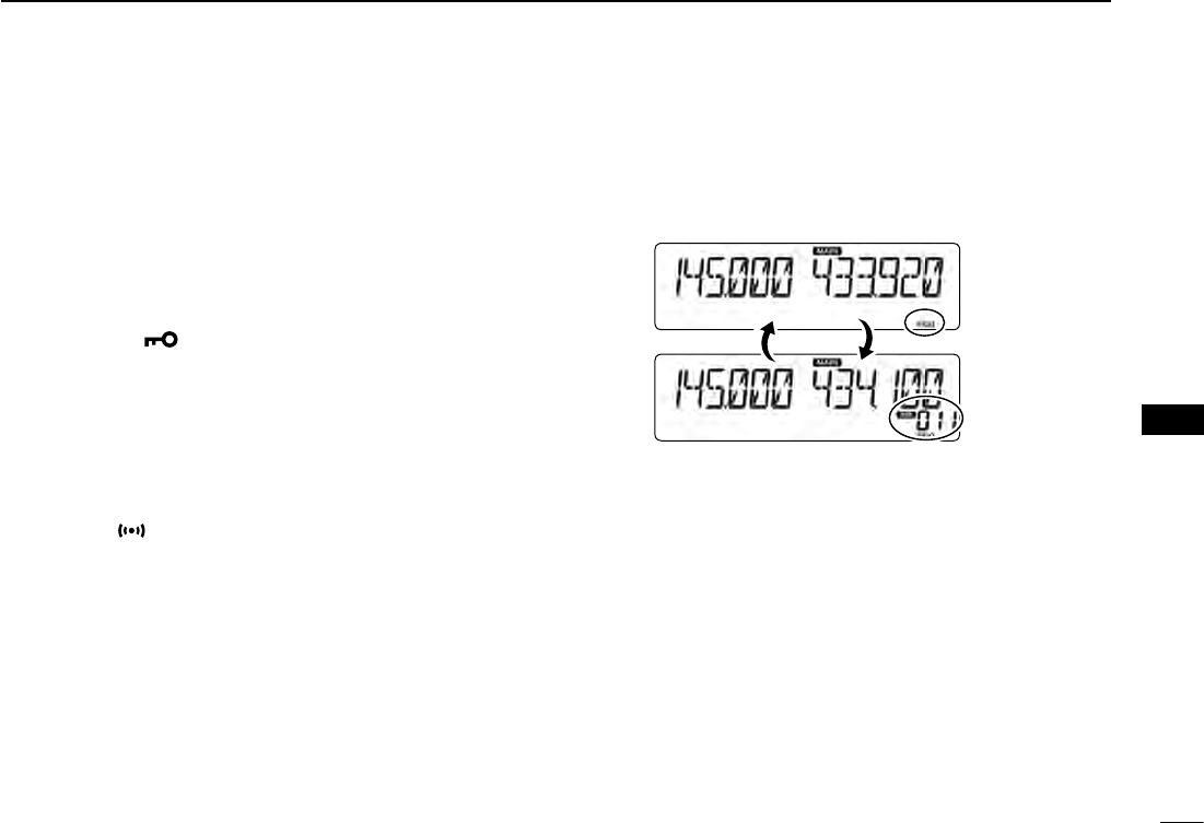
New2001
2
6
PRIORITY WATCH
New2001
6
PRIORITY WATCH
VFO and a priority channel ■
VFO frequency and a priority channel D
Checks the selected priority channel every 5 seconds, while
receiving on a VFO frequency.
Set the VFO frequency. q (p. ??)
Set the priority channel. w (p. ??)
•SelectaMemorychannel,BankchannelorCallchannel.
Push [MENU e]C.
•EnterstheMENUmode.
r Rotate [DIAL]S to select “PRIO” (Priority scan).
Push [ tï]D.
Rotate [DIAL] yS to select “ON” or “Bell.”
•ON:When a signal is received on the priority channel,
the channel is automatically selected.
•Bell:When a signal is received on the priority channel,
the “ ” icon is displayed in the VFO screen.
Push [ uï]D.
Push [MAIN BAND] iS.
•ExitstheMENUmode.
•The“PRIO”iconappears,andthePrioritywatchstarts.
•TocancelthePrioritywatch,select“OFF”inthestepy.
Example:
Checks Memory channel “11” while receiving on
433.920 MHz.
Checks the Memory channel every 5 seconds.
Appears
Priority
channel
VFO scan and a priority channel D
Checks the selected priority channel every 5 seconds, during
a VFO mode scan.
Operate steps q q through i as shown to the left.
•The“PRIO”iconappears,andthePrioritywatchstarts.
Hold down [V/MHz SCAN] wS for 1 second.
Rotate [DIAL] eS to select a desired scan type.
Push [V/MHz SCAN] rS.
•TheVFOscanstarts.
3
6PRIORITY WATCH
New2001 New2001
New2001
VFO and a Memory/Bank scan ■
VFO frequency and a Memory/Bank scan D
Sequentially checks the Memory or Bank channels every
5 seconds, while receiving on a VFO frequency.
Set the VFO frequency. q (p. ??)
Selects the Memory mode. w (p. ??)
Hold down [V/MHz SCAN] eS for 1 second.
Rotate [DIAL] rS to select a desired scan type.
Push [V/MHz SCAN] tS.
•TheMemoryscanstarts.
Push [MENU y]C.
•EnterstheMENUmode.
u Rotate [DIAL]S to select “PRIO” (Priority scan).
Push [ iï]D.
Rotate [DIAL] oS to select “ON” or “Bell.”
•ON:When a signal is received on the priority channel,
the channel is automatically selected.
•Bell:When a signal is received on the priority channel,
the “ ” icon is displayed in the VFO screen.
!0 Push [ï]D.
!1 Push [MAIN BAND]S.
•ExitstheMENUmode.
•The“PRIO”iconappears,andthePrioritywatchstarts.
•TocancelthePrioritywatch,select“OFF”inthestep!.
Example:
Sequentially c
hecks the Memory channels while re-
ceiving on 433.920 MHz.
Checks the Memory channels every
5 seconds.
Appears
The Memory channels are
sequentially checked.
VFO scan and a Memory/Bank scan D
Sequentially checks the Memory or Bank channels every 5
seconds during a VFO scan.
Operate steps q q through !1 as shown to the left.
•The“PRIO”iconappears,andthePrioritywatchstarts.
Hold down [V/MHz SCAN] wS for 1 second.
Rotate [DIAL] eS to select a desired scan type.
Push [V/MHz SCAN] rS.
•TheVFOscanstarts.
The C, S or D in the instructions indicate the part of the
controller.
C: Center, S: Side, D: Display
1
New2001New2001
SPECIFICATIONS
12
New2001
General D
•Frequencycoverage:
EUR RX 118–174 MHz*1, 375–550 MHz*2
TX 144–146 MHz, 430–440 MHz
ITR RX 118–136.99166 MHz*3, 144–146 MHz,
430–434 MHz, 435–438 MHz
TX 144–146 MHz, 430–434 MHz,
435–438 MHz
TPE RX 144–146 MHz, 430–432 MHz
TX 144–146 MHz, 430–432 MHz
USA RX 118–174 MHz*4, 375–550 MHz*5
TX 144–148 MHz, 430–450 MHz*5
KOR RX 144–146 MHz, 430–440 MHz
TX 144–146 MHz, 430–440 MHz
EXP RX 118–174 MHz*4, 375–550 MHz*2
TX 137–174 MHz*4, 400–470 MHz*2
CHN RX 118–174 MHz*1, 375–550 MHz*2
TX 137–174 MHz*1, 400–470 MHz*2
*1 Guaranteed only 144–146 MHz *2 Guaranteed only 430–440 MHz
*3 Not guaranteed
*4 Guaranteed only 144–148 MHz
*5 Guaranteed only 430–450 MHz
•Mode: F2D/F3E(FM/FM-N),
A3E (AM/AM-N) RX only
•No.ofmemorychannels: 1000channels
•No.ofprogramscanchannels:25channels
(2 edge frequencies in
each channel)
•No.ofcallchannels: 2channels
•Antennaconnector: SO-239
•Antenna impedance: 50 ø
•Usabletemperaturerange: –10˚Cto+60˚C;+14˚Fto+140˚F
•Frequencystability: ±2.5ppm
(10˚Cto+60˚C;+14˚Fto+140˚F)
•Frequencyresolution: 5kHz,6.25kHz,8.33kHz,10kHz,
12.5 kHz, 15 kHz, 20 kHz, 25 kHz,
30 kHz, 50 kHz
The 8.33 kHz step is not selectable,
depending on the operating band or
mode.
•Powersupply: 13.8VDC±15%(negativeground)
•Currentdrain:
Transmit
Maximum current drain: ≤ 10.5 A (TPE version)
≤ 13.0 A (Other versions)
Receive
Standby: ≤ 1.2 A
Maximum audio: ≤ 1.8 A
•Dimensions(projectionsnotincluded):
Main unit: 150(W) × 40(H) × 151(D) mm;
5.9(W) × 1.6(H) × 5.94(D) inch
Controller:
150(W) × 50(H) × 27.2(D) mm;
5.91(W) × 1.97(H) × 1.07(D) inch
•Weight(approximately):
Main unit: 1.2 kg; 2.6 lb
Controller: 140 g; 4.9 oz

New2001
2
12
SPECIFICATIONS
New2001
12
SPECIFICATIONS
Transmitter D
•Modulationsystem:
FM/FM-N: Variable reactance frequency
modulation
•MaxDeviation:
FM: ≤ ±5.0 kHz
FM-N: ≤ ±2.5 kHz
•Microphoneimpedance: 600ø
•Spuriousemission: ≤ –60 dBc
•Outputpower: High25W,Mid15W,Low5W
(TPE version)
High 50 W, Mid 15 W, Low 5 W
(Other versions)
Receiver D
•Receivesystem: Doublesuperheterodynesystem
•IFfrequencies:
A band 1st IF 38.85 MHz
2nd IF 450 kHz
B band 1st IF 46.35 MHz
2nd IF 450 kHz
•Sensitivity(exceptspuriouspoints)
Amateur bands
FM/FM-N (12 dB SINAD)
≤ 0.18 μV
Except Amateur bands
FM/FM-N (12 dB SINAD)
≤ 0.32 μV (137.000 to 159.995 MHz)
≤ 0.56 μV (160.000 to 174.000 MHz)
≤ 0.56 μV (375.000 to 399.995 MHz)
≤ 0.32 μV (400.000 to 499.995 MHz)
≤ 0.56 μV (500.000 to 550.000 MHz)
AM (10 dB S/N)
≤ 1 μV (118.000 to 136.99166 MHz)
•Squelchsensitivity: ≤ 0.13 μV (Threshold)
•Selectivity:
FM ≥ 60 dB
FM-N ≥ 55 dB
•Spuriousandimagerejectionratio:
≥ 60 dB
≥ 55 dB (A band UHF)
•AFoutputpower: ≥ 2.0 W
(at10%distortionwithan8ø load)
•AFoutputimpedance: 8ø
c
New2001New2001
INFORMATION
15
COUNTRY CODE LIST
•ISO3166-1
Country Codes Country Codes
1
2
3
4
5
6
7
8
9
10
11
12
13
14
15
16
17
Austria
Belgium
Bulgaria
Croatia
Czech Republic
Cyprus
Denmark
Estonia
Finland
France
Germany
Greece
Hungary
Iceland
Ireland
Italy
Latvia
AT
BE
BG
HR
CZ
CY
DK
EE
FI
FR
DE
GR
HU
IS
IE
IT
LV
18
19
20
21
22
23
24
25
26
27
28
29
30
31
32
33
Liechtenstein
Lithuania
Luxembourg
Malta
Netherlands
Norway
Poland
Portugal
Romania
Slovakia
Slovenia
Spain
Sweden
Switzerland
Turkey
United Kingdom
LI
LT
LU
MT
NL
NO
PL
PT
RO
SK
SI
ES
SE
CH
TR
GB
FCC INFORMATION
•FORCLASSBUNINTENTIONALRADIATORS:
This equipment has been tested and found to comply with the
limits for a Class B digital device, pursuant to part 15 of the
FCC Rules. These limits are designed to provide reasonable
protection against harmful interference in a residential instal-
lation. This equipment generates, uses and can radiate radio
frequency energy and, if not installed and used in accordance
with the instructions, may cause harmful interference to radio
communications. However, there is no guarantee that inter-
ference will not occur in a particular installation. If this equip-
ment does cause harmful interference to radio or television
reception, which can be determined by turning the equipment
off and on, the user is encouraged to try to correct the inter-
ference by one or more of the following measures:
•Reorientorrelocatethereceivingantenna.
•Increasetheseparationbetweentheequipmentandre-
ceiver.
•Connecttheequipmentintoanoutletonacircuitdifferent
from that to which the receiver is connected.
•Consultthedealeroranexperiencedradio/TVtechnician
for help.
CAUTION: Changes or modifications to this device, not ex-
pressly approved by Icom Inc., could void your authority to
operate this device under FCC regulations.
1-1-32 Kamiminami, Hirano-ku, Osaka 547-0003, Japan
New2001
A-7194H-1EX
Printed in Japan
© 2014 Icom Inc.
Printed on recycled paper with soy ink.
<Intended Country of Use>
■ AT ■ BE ■ CY ■ CZ ■ DK ■ EE
■ FI ■ FR ■ DE ■ GR ■ HU ■ IE
■ IT ■ LV ■ LT ■ LU ■ MT ■ NL
■ PL ■ PT ■ SK ■ SI ■ ES ■ SE
■ GB ■ IS ■ LI ■ NO ■ CH ■ BG
■ RO ■ TR ■ HR
#02 EUR
<Intended Country of Use>
■ AT ■ BE ■ CY ■ CZ ■ DK ■ EE
■ FI ■ FR ■ DE ■ GR ■ HU ■ IE
■ IT ■ LV ■ LT ■ LU ■ MT ■ NL
■ PL ■ PT ■ SK ■ SI ■ ES ■ SE
■ GB ■ IS ■ LI ■ NO ■ CH ■ BG
■
RO
■
TR
■
HR
#03 ITR