ICOM orporated 369700 VHF Air Band Transceiver User Manual
ICOM Incorporated VHF Air Band Transceiver
User Manual
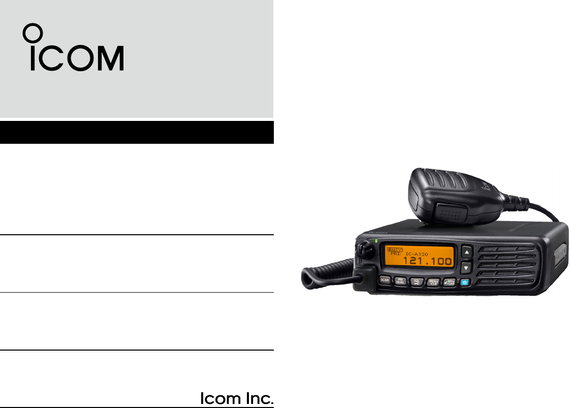
VHF AIR BAND TRANSCEIVERS
BASIC MANUAL
This device complies with Part 15 of the FCC
Rules. Operation is subject to the condition that
this device does not cause harmful interference.
iA120
iA120E
IMPORTANT
READ ALL INSTRUCTIONS carefully and completely
before using the transceiver.
SAVE THIS INSTRUCTION MANUAL — This
instruction manual contains important operating instructions
for the IC-A120 and IC-A120E.
The explicit denitions below apply to this instruction manual.
WORD DEFINITION
RWARNING! Personal injury, re hazard or electric
shock may occur.
CAUTION Equipment damage may occur.
NOTE
If disregarded, inconvenience only. No risk
of personal injury, re or electric shock.
i
EXPLICIT DEFINITIONS
About E-marking: Detailed installation notes for Icom mobile
transceivers to be tted into vehicles are available. Please
contact your Icom dealer or distributor.
CAUTION: Changes or modications to this transceiver, not
expressly approved by Icom Inc., could void your authority to
operate this transceiver under FCC regulations.
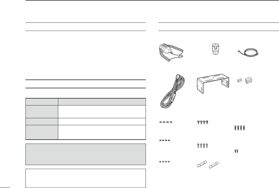
SUPPLIED ACCESSORIES
* Used for optional unit installation.
Ask the technical dealer for details.
Microphone Microphone hanger Microphone
hanger cable
DC power cable Mounting bracket Sponges*
Flat washers Bracket bolts Self-tapping screws
(5×16)
Spring washers Mounting screws
(5×12)
Nuts Fuses (10 A)
Self-tapping screws
(3×16, for Microphone
hangar)

BE CAREFUL! The transceiver will become hot when
operating continuously for long periods.
USE the specied microphone only. Other microphones have
different pin assignments and may damage the transceiver.
Place the transceiver in a secure place to avoid inadvertent use by
children.
KEEP the transceiver away from the heavy rain, and never
immerse it in the water. The transceiver meets IP54* requirements
for dust-protection and splash resistance. However, once the
transceiver has been dropped, dust protection and splash
resistance cannot be guaranteed due to the fact that the transceiver
may be cracked, or the waterproof seal damaged, and so on.
*Only when the supplied microphone is attached.
Icom, Icom Inc. and Icom logo are registered trademarks of Icom
Incorporated (Japan) in Japan, the United States, the United Kingdom,
Germany, France, Spain, Russia, Australia, New Zealand, and/or other
countries.
The Bluetooth word mark and logos are registered trademarks owned by
Bluetooth SIG, Inc. and any use of such marks by Icom inc. is under license.
All other products or brands are registered trademarks or trademarks of their
respective holders.
ii
PRECAUTIONS
R WARNING! NEVER connect the transceiver to an AC
outlet. This may pose a re hazard or result in an electric shock.
R WARNING! NEVER connect the transceiver to a power
source of more than 31.5 V DC. This could damage the transceiver.
R WARNING! NEVER cut the DC power cable between
the DC plug and fuse holder. If an incorrect connection is made
after cutting, the transceiver might be damaged.
R WARNING! NEVER place the transceiver where normal
operation of the vehicle may be hindered or where it could cause
bodily injury.
CAUTION: NEVER expose the transceiver to rain, snow or
any liquids.
DO NOT operate or place the transceiver in areas with
temperatures below –30°C (–22°F) or above +60°C (+140°F), or in
areas subject to direct sunlight, such as the dashboard.
DO NOT operate the transceiver without running the vehicle’s
engine. The vehicle’s battery will quickly run out when the
transceiver transmits while the vehicle’s engine is OFF.
DO NOT place the transceiver in excessively dusty
environments.
DO NOT place the transceiver against walls. Otherwise heat
dissipation will be obstructed.
DO NOT use harsh solvents such as benzine or alcohol when
cleaning, as they damage the transceiver surfaces.
CAUTION: In Canada, use of 8.33 kHz Channel Spacing of this
radio is strictly prohibited and shall not be used.

iii
NE PAS placer l'émetteur-récepteur dans un environnement
excessivement poussiereux ou en plein soleil.
NE PAS placer l'émetteur-récepteur contre un mur pour ne pas
gêner la dispersion de la chaleur.
NE PAS utiliser de solvants agressifs tels que l'essence ou
l'alcool pour nettoyer le l’émetteur-récepteur, en raison des risques
d'endommager la surface du l’émetteur-récepteur.
ATTENTION! L’émetteur-récepteur chauffe en cas d’utilisation
continue sur une longue durée.
Utiliser exclusivement un microphone Icom (fourni d’origine ou en
option). La repartition des broches des microphones des autres
fabricants est différente et leur connexion à l’IC-A120/IC-A120E
peut endommager l’émetteur-récepteur.
Placer l’émetteur-récepteur hors de portée des enfants pour éviter
toute utilisation inopinée.
PLACEZ l'émetteur-récepteur loin d'une forte pluie et ne
jamais l'immerger dans l'eau. Cet émetteur-récepteur répond aux
exigences de la norme IP54* en matière de protection contre
la poussière et de résistance aux éclaboussures. Toutefois,
si l'émetteur-récepteur tombe par terre, la protection contre la
poussière et la résistance aux éclaboussures ne peuvent être
garanties, car l'appareil peut être ssuré ou le joint d'étanchéité
peut être endommagé, etc.
*Seulement lorsque le microphone fourni est xé.
PRÉCAUTIONS
R AVERTISSEMENT! NE JAMAIS connecter
l'émetteur-récepteur a une alimentation CA au risque de
provoquer un incendie ou un choc electrique.
R AVERTISSEMENT! NE JAMAIS brancher
l’émetteur-récepteur sur une source d’alimentation de plus de
31.5 V CC. NE JAMAIS émettre lorsque le coupleur est activé (ON),
alors qu'aucune antenne n'est raccordée, au risque d'endommager
gravement l'émetteur-récepteur.
R AVERTISSEMENT! NE JAMAIS couper le câble
d’alimentation CC entre la prise CC à l’arrière de l’émetteur-
récepteur et le porte fusible. L’émetteur-récepteur peut être
endommagé par la suite en cas de connexion inappropriée.
MISE EN GARDE: NE JAMAIS placer l’émetteur-
récepteur à un emplacement où il pourrait gêner le fonctionnement
normal du navire ou provoquer des blessures corporelles.
MISE EN GARDE: NE JAMAIS exposer l’émetteur-
récepteur à la pluie, à la neige ou à tout autre liquide.
NE PAS utiliser ou placer l’émetteur-récepteur dans des zones
où la temperature est inférieure à –30°C (–22°F) ou supérieure
à +60°C (+140°F) ou dans des zones soumises au rayonnement
solaire direct, telles le tableau de bord.
En utilisation mobile, NE PAS utiliser un emetteur-recepteur
embarque avec le moteur du vehicule arrete. La batterie du
véhicule sera rapidement épuisé lorsque la radio transmet lorsque
le moteur du véhicule est éteint. MISE EN GARDE: Utilisation de 8,33 kHz Espacement des
canaux de cette radio est strictement interdite et ne doit pas être
utilisé au Canada.
iv
SAFETY TRAINING INFORMATION
Your Icom radio generates RF
electromagnetic energy during transmit
mode. This radio is designed for and
classied as “Occupational Use Only,”
meaning it must be used only during the
course of employment by individuals aware
of the hazards, and the ways to minimize
such hazards. This radio is NOT intended
for use by the “General Population” in an
uncontrolled environment.
• For compliance with FCC and Industry Canada RF
Exposure Requirements, the transmitter antenna
installation shall comply with the following two conditions:
1. The transmitter antenna gain shall not exceed 0 dBi.
2. The antenna is required to be located outside of a
vehicle and kept at a distance of 53 centimeters or
more between the transmitting antenna of this device
and any persons during operation. For a small vehicle,
the antenna as worst case, the antenna shall be
located on the roof top at any place on the centre line
along the vehicle in order to achieve 53 centimeters
separation distance. In order to ensure this distance is
met, the installation of the antenna must be mounted
at least 53 centimeters away from the nearest edge
of the vehicle in order to protect against exposure to
bystanders.
To ensure that your exposure to RF
electromagnetic energy is within the FCC
allowable limits for occupational use,
always adhere to the following guidelines:
• DO NOT operate the radio without a proper antenna
attached, as this may damage the radio and may also
cause you to exceed FCC RF exposure limits. A proper
antenna is the antenna supplied with this radio by the
manufacturer or an antenna specically authorized by the
manufacturer for use with this radio.
• DO NOT transmit for more than 50% of total radio use time
(“50% duty cycle”). Transmitting more than 50% of the time
can cause FCC RF exposure compliance requirements
to be exceeded. The radio is transmitting when the “TX”
indicator appears. You can cause the radio to transmit by
pressing the PTT switch.
Electromagnetic Interference/Compatibility
During transmissions, your Icom radio generates RF energy
that can possibly cause interference with other devices or
systems. To avoid such interference, turn off the radio in
areas where signs are posted to do so. DO NOT operate
the transmitter in areas that are sensitive to electromagnetic
radiation such as hospitals, aircraft, and blasting sites.
WARNING
CAUTIO N
v
INFORMATION EN MATIÈRE DE SÉCURITÉ
Votre radio Icom produit une énergie
électromagnétique de radiofréquences (RF), en
mode de transmission. Cette radio est conçue
pour un «usage professionnel seulement» et
classée comme tel, ce qui signie qu'elle doit
être utilisée uniquement dans le cadre d'un
travail par des personnes conscientes des
dangers et des mesures visant à minimiser
ces dangers. Elle N'EST PAS conçue pour
une «utilisation grand public», dans un
environnement non contrôlé.
• An de satisfaire aux exigences de la FCC et d'Industrie Canada
en matière d'exposition aux RF, il est nécessaire que l'antenne soit
installée conformément aux deux conditions suivantes:
1. Le gain de l'antenne du radio émetteur ne doit pas dépasser 0
dBi.
2. Il faut que l'antenne émettrice de cet appareil soit placée
à l'extérieur d'un véhicule et tenue éloignée d'au moins 53
centimètres de toute personne pendant le fonctionnement.
Dans le pire des cas, pour un petit véhicule, l'antenne doit
être placée sur le toit, n'importe où dans l'axe central du
véhicule, an de respecter une distance de 53 cm du bord le
plus rapproché du véhicule et ainsi éviter que les personnes
présentes soient exposées.
An de vous assurer que votre exposition à une
énergie électromagnétique de RF se situe dans les
limites permises par la FCC pour une utilisation
grand public, veuillez en tout temps respecter les
directives suivantes:
•
NE PAS faire fonctionner la radio sans qu'une antenne appropriée
y soit xée, car ceci risque d'endommager la radio et causer une
exposition supérieure aux limites établies par la FCC. L'antenne
appropriée est celle qui est fournie avec cette radio par le fabricant
ou une antenne spécialement autorisée par le fabricant pour être
utilisée avec cette radio.
• NE PAS émettre pendant plus de 50% du temps total d'utilisation
de l'appareil («50% du facteur d'utilisation»). Émettre pendant plus
de 50% du temps total d'utilisation peut causer une exposition
aux RF supérieure aux limites établies par la FCC. La radio est
en train d’émettre lorsque le témoin du mode de transmission
s'afche sur l'écran ACL. La radio émettra si vous appuyez sur le
bouton du microphone.
Interférence électromagnétique et compatibilité
En mode de transmission, votre radio Icom produit de l'énergie de
RF qui peut provoquer des interférences avec d'autres appareils ou
systèmes. Pour éviter de telles interférences, mettez la radio hors
tension dans les secteurs où une signalisation l’exige. NE PAS faire
fonctionner l'émetteur dans des secteurs sensibles au rayonnement
électromagnétique tels que les hôpitaux, les aéronefs et les sites de
dynamitage.
A
VERTISSEMENT
MISE EN GARDE

vi
TABLE OF CONTENTS
IMPORTANT ..........................................................................i
EXPLICIT DEFINITIONS .......................................................i
SUPPLIED ACCESSORIES .................................................. i
PRECAUTIONS .................................................................... ii
PRÉCAUTIONS ....................................................................iii
SAFETY TRAINING INFORMATION ................................... iv
INFORMATION EN MATIÈRE DE SÉCURITÉ ..................... v
1 PANEL DESCRIPTION ................................................1–2
■Front panel ................................................................... 1
■Function display ...........................................................2
2 BASIC OPERATION ....................................................3–5
■Turning ON the transceiver .......................................... 3
■Receiving and transmitting ...........................................4
■Adjusting the squelch ................................................... 5
3 Bluetooth® OPERATION ............................................6–8
■ Operating Bluetooth® ...................................................6
■Electromagnetic Interference .......................................6
■Pairing with a headset ..................................................7
■AF Output setting .........................................................7
■ Disconnecting from a headset .....................................8
■ Unpairing a headset ..................................................... 8
4 MENU MODE .............................................................9–10
■Using the Menu mode .................................................. 9
■Menu item list ............................................................... 9
5 SPECIFICATIONS AND OPTIONS ......................... 11–12
■Specications ............................................................. 11
■Options .......................................................................12
6 INFORMATION ........................................................ 13–14
■ Firmware version identication ..................................13
■Disposal .....................................................................13
■Country code list ........................................................13
■ VFO channel ID list ....................................................14
■ FCC information ......................................................... 15
INDEX.................................................................................16
1
1PANEL DESCRIPTION
1
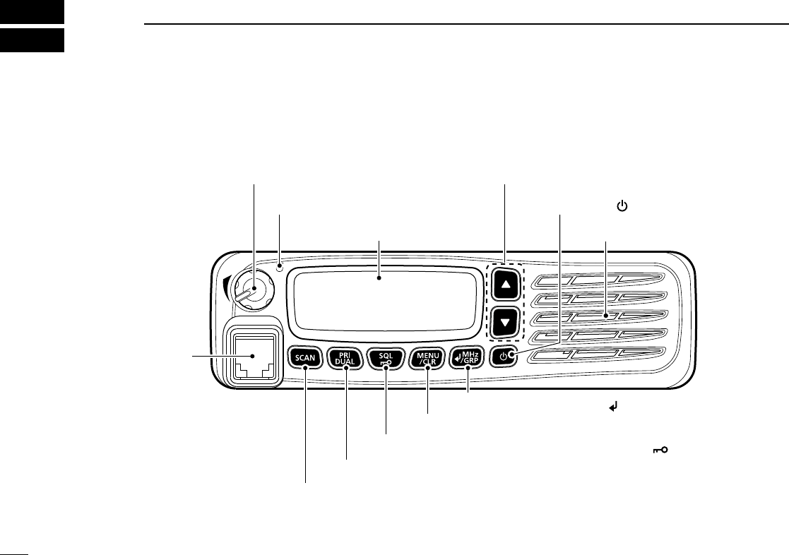
■Front panel
VOLUME CONTROL KNOB
STATUS INDICATOR
FUNCTION DISPLAY
UP/DOWN KEYS [∫]/[√]
POWER KEY []
SPEAKER
ENTER/MHz/GRP KEY []/[MHz]/[GRP]
MENU/CLEAR KEY [MENU]/[CLR]
SQUELCH ADJUSTMENT/LOCK KEY [SQL]/[ ]
PRIORITY CHANNEL/DUALWATCH KEY [PRI]/[DUAL]
SCAN KEY [SCAN]
MICROPHONE
CONNECTOR
2
1
PANEL DESCRIPTION
01
2
3
4
5
6
7
8
9
0
1
2
13
14
15
16
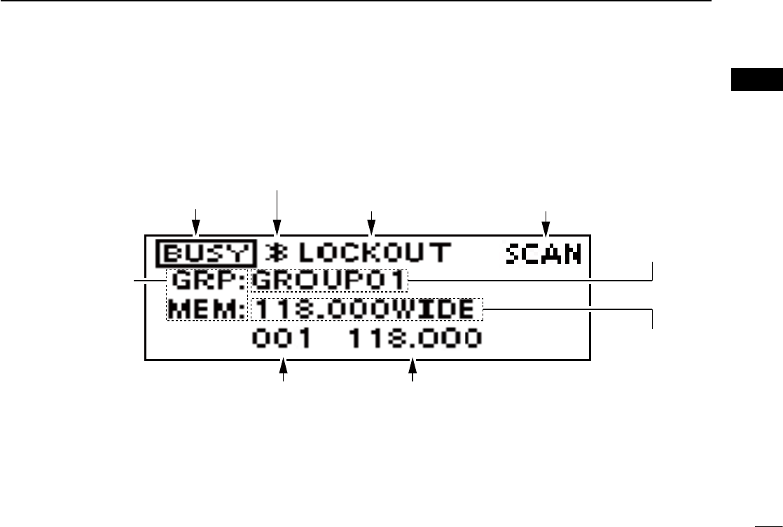
■Function display
RX
TX/BUSY ICON
BLUETOOTH ICON
LOCKOUT ICON SCAN/CHANNEL ICON
CHANNEL READOUT FREQUENCY READOUT
GROUP NAME
READOUT
MEMORY
NAME
READOUT
OPERA
TING MODE
ICON
3
2BASIC OPERATION
■Turning ON the transceiver
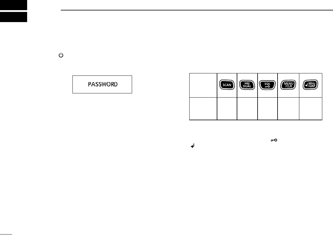
Hold down [ ] for 1 second to turn ON the power.
If the transceiver is preset for a start-up password, enter the
6 digits password.
While in the Password Entry mode, “PASSWORD” is
displayed.
DEntering the password
Enter the password in the following manner.
KEY
NUMBER
0
5
1
6
2
7
3
8
4
9
Example:
If the password is 513824, push [SCAN], [PRI/DUAL],
[MENU/CLR], [MENU/CLR], [SQL/ ], and then push
[/MHz/GRP].
• Note that each key represents 2 digits. That means,
“123456” and “678901” are entered in exactly the same
way (requires no multiple or extended pushing.)
• The entered password will not be displayed.
• If “PASSWORD” does not disappear after entering, the
entered password is incorrect. Turn OFF the transceiver,
and then try again.
4
2
BASIC OPERATION
1
02
3
4
5
6
7
8
9
10
11
12
13
14
15
16
Setting the frequency in the VFO mode
(For only EXP, USA, and EUR versions.)
1) Switch the transceiver to the VFO mode.
➥ Select “VFO MODE” group in the Menu mode and
then push [ /MHz/GRP].
2) Set the MHz digit.
➥ Push [ /MHz/GRP], and then push [∫] or [√].
• The MHz digit blinks.
3) Exit the MHz Digit Selection mode.
➥ Push [ /MHz/GRP] again.
4) Set the kHz digit.
➥ Push [∫] or [√].
■Receiving and transmitting
1. Setting the frequency
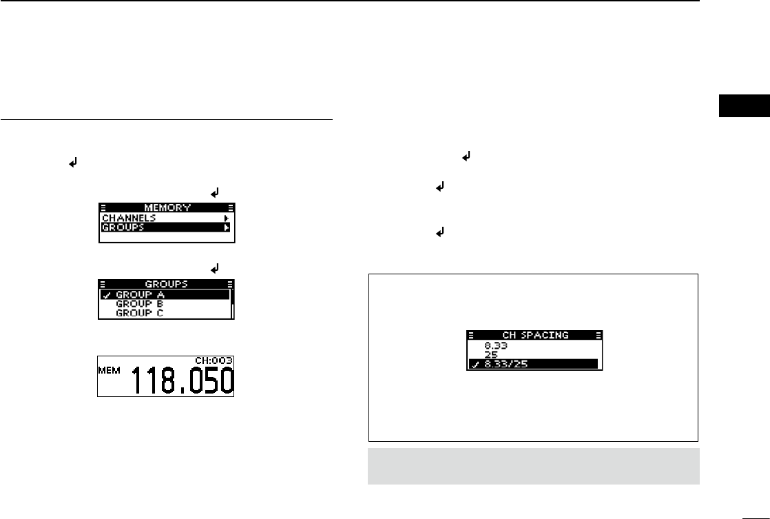
Setting the frequency in the Memory mode
1) Open the “MEMORY” menu.
➥ Push [ /MHz/GRP].
2) Select “GROUPS” item.
➥ Push [∫] or [√], and then push [ /MHz/GRP].
3) Select a desired group.
➥ Push [∫] or [√], and then push [ /MHz/GRP].
4) Select a desired channel.
➥ Push [∫] or [√].
TIP: You can select the channel spacing in the “CH
SPACING” item*.
* The menu may not be displayed, depending on the transceiver’s
setting. Ask your authorized Icom dealer or transceiver
administrator for details.
MENU > SETTINGS > FUNCTIONS > CH SPACING
CAUTION: In Canada, use of 8.33 kHz Channel Spacing of
this radio is strictly prohibited and shall not be used.
5
2BASIC OPERATION
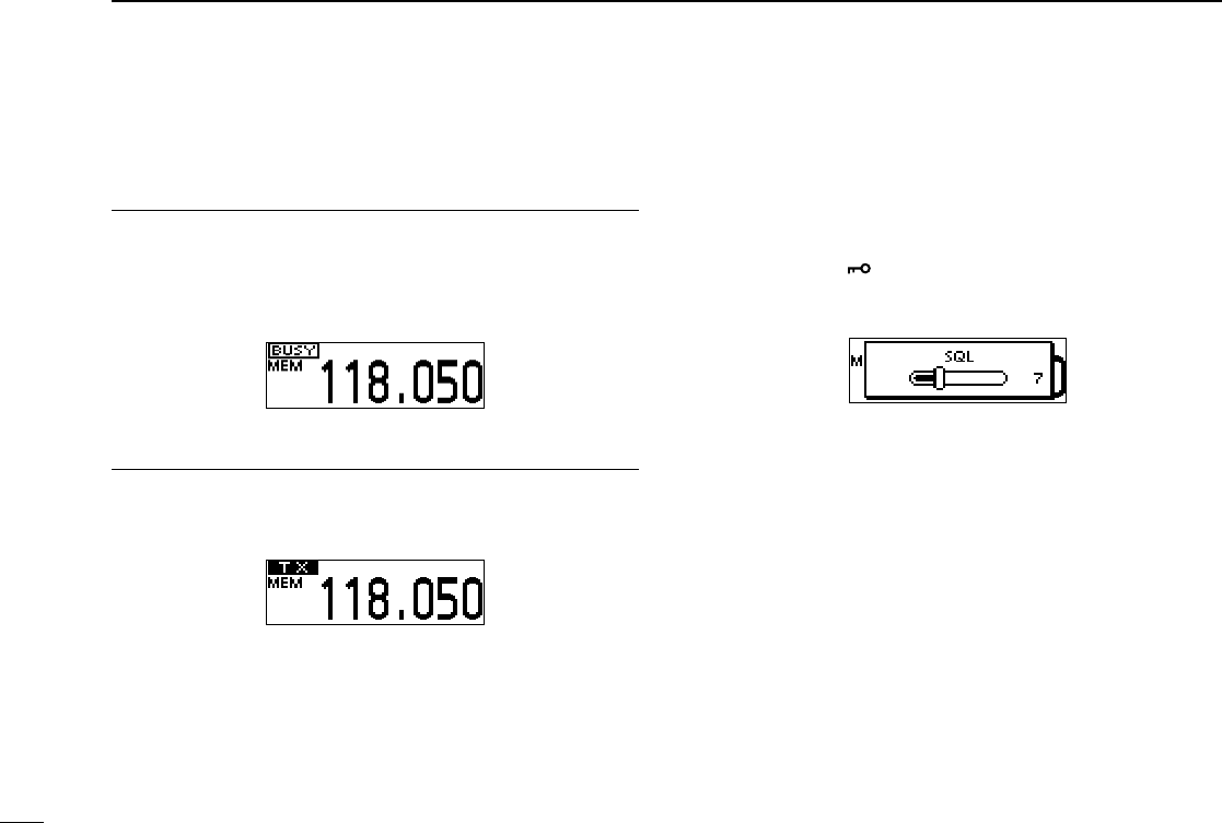
2. Receiving
When receiving a signal, “BUSY” is displayed and audio is
heard.
• Rotate volume control knob to adjust the audio level.
• Adjust the squelch if necessary. See ‘Adjusting the squelch’
to the right for details.
3. Transmitting
1) Hold down [PTT], and then speak at your normal voice
level.
• “TX” is displayed.
2) Release [PTT] to receive.
Information
To maximise the clarity of the signal, Hold the microphone
about 5 to 10 cm (2 to 4 inches) from your mouth.
■Receiving and transmitting (Continued) ■Adjusting the squelch
Adjust the squelch to mute undesired noise when no signal
received.
1) Open the “SQL” window.
➥ Push [SQL/ ].
2) Adjust the squelch.
➥ Push [∫] or [√] to select the desired squelch level.
6
3
Bluetooth® OPERATION
02
03
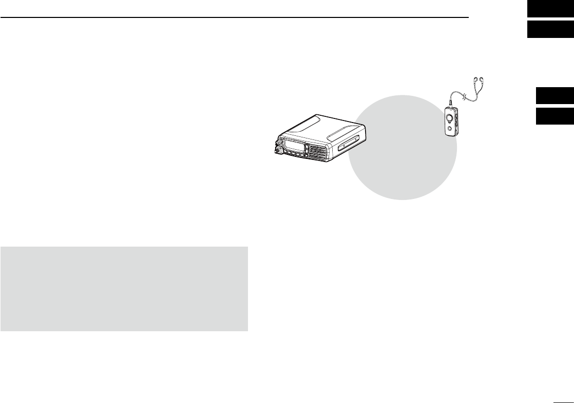
■ Operating Bluetooth®
If the UT-133A Bluetooth® unit is installed in the transceiver,
you can connect a Bluetooth® headset.
When you connect the VS-3 Bluetooth® headset to the
transceiver, you can wirelessly transmit and receive the
headset audio.
The VS-3 has a [PTT] switch, so you can transmit in the
same way as using the transceiver’s [PTT] switch.
Communication range of Bluetooth
®
is approximately 10
meters (32.8 ft).
■Electromagnetic Interference
When you use a Bluetooth
®
headset, pay attention to the
following:
Bluetooth
®
devices operate in the 2.4 GHz band.
The 2.4 GHz band is also used by other devices, such as
Wireless LAN products, microwave ovens, RFID systems,
amateur radio stations, and so on.
When using the Bluetooth
®
headset near such devices,
interference may occur, causing a decrease in
communication speed, and an unstable connection.
In such cases, use the headset away from the other
devices, or stop using those headsets.
The Bluetooth
®
communication range may vary, depending
on your operating environment.
Microwave ovens or Wireless LANs may cause
interference. In that case, stop using those devices or
move away from them.
This Bluetooth
®
headset has a usable range. If
communication is unstable, move within the range.
Bluetooth®
Transceiver with the
UT-133A Bluetooth® unit
Optional Vs-3
Bluetooth® headset
7
3Bluetooth® OPERATION
■Pairing with a headset
These instructions describe pairing with the VS-3 Bluetooth®
headset as example. You can pair a maximum of 7
Bluetooth® headsets with the transceiver.
• If you try to pair a Bluetooth
®
headset to a transceiver that already
has 7 headsets paired with it, the oldest headset will automatically
be unpaired.
1. Turning ON transceiver’s Bluetooth® function
1) Open the “BLUETOOTH FUNC” menu.
2) Activate the Bluetooth® unit.
➥ Select “ON” and push [ /MHz/GRP].
2. Entering the Pairing mode of the VS-3
• See the VS-3’s instruction manual for details.
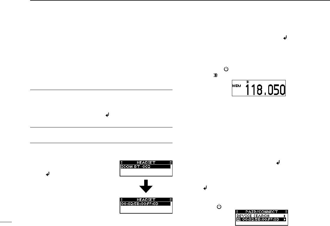
3. Pairing the Bluetooth® headset
1) Open the “DEVICE SEARCH” menu.
3) Select the desired headset to pair.
➥ Push [∫] or [√] and then push [ /MHz/GRP].
• A passkey or PIN code may be required to pair,
depending on the headset. Refer to your headset’s
instructions for details.
4) Exit the Menu mode.
➥ Push [ ].
• “ ” is displayed if the headset is correctly paired.
■Connecting a paired headset
If you have a previously paired headset, follow the steps
below to connect it.
1) Open the “PAIR/CONNECT” menu.
MENU > BLUETOOTH > PAIR/CONNECT
• The paired headsets are displayed.
2) Select the desired headset to connect.
➥ Push [∫] or [√] and then push [ /MHz/GRP].
• “CONNECT” and “UNPAIR” is displayed.
3) Connect the headset.
➥ Select “CONNECT” and then push
[/MHz/GRP].
• The check mark “4” in the box is displayed.
4) Exit the Menu mode.
➥ Push [ ].
2) Search for a headset to pair.
➥ Select “HEADSET” and push
[/MHz/GRP].
•
The found headsets are displayed.
• “NOT FOUND” is displayed if no
headset is found.
• Push [MENU/CLR] to cancel
searching.
• The headset name changes to
its Bluetooth® device address in
5 seconds.
MENU > SETTINGS > BLUETOOTH > BLUETOOTH FUNC
MENU > BLUETOOTH > PAIR/CONNECT >DEVICE SEARCH
8
3
Bluetooth® OPERATION
03
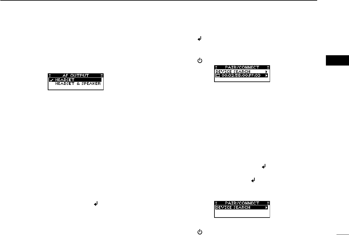
■Setting AF Output
You can select the AF output option in the
“AF OUTPUT”
menu.
MENU > SETTINGS > BLUETOOTH > HEADSET SET >
AF OUTPUT
HEADSET: Outputs audio to the connected
Bluetooth® headset.
HEADSET & SPEAKER: Outputs audio to both the
connected Bluetooth® headset and
the transceiver’s speaker.
You can disconnect from a headset without cancelling the
pairing.
1) Open the “PAIR/CONNECT” menu.
MENU > BLUETOOTH > PAIR/CONNECT
• The connected headsets are displayed.
2) Select the desired headset to disconnect.
➥ Push [∫] or [√] and then push [ /MHz/GRP].
• “DISCONNECT” is displayed.
■ Disconnecting a headset
3) Disconnect the headset.
➥ Push [ /MHz/GRP], and then select [YES].
• The check mark “4” in the box disappears.
4) Exit the Menu mode.
➥ Push [ ].
■ Unpairing a headset
You can unpair a Bluetooth® headset.
Before unpairing a connected
headset
, disconnect it.
1) Open the “PAIR/CONNECT” menu.
MENU > BLUETOOTH > PAIR/CONNECT
• The paired headsets are displayed.
2) Select the desired headset to unpair.
➥ Push [∫] or [√] and then push [ /MHz/GRP].
3) Unpair the headset.
➥ Select “UNPAIR” and push [ /MHz/GRP].
• The headset name disappears from the “PAIR/CONNECT”
menu.
4) Exit the Menu mode.
➥ Push [ ].
■Using the Menu mode
You can set seldom changed settings in the Menu mode.
You can customize the transceiver settings to suit your
preference and operating style.
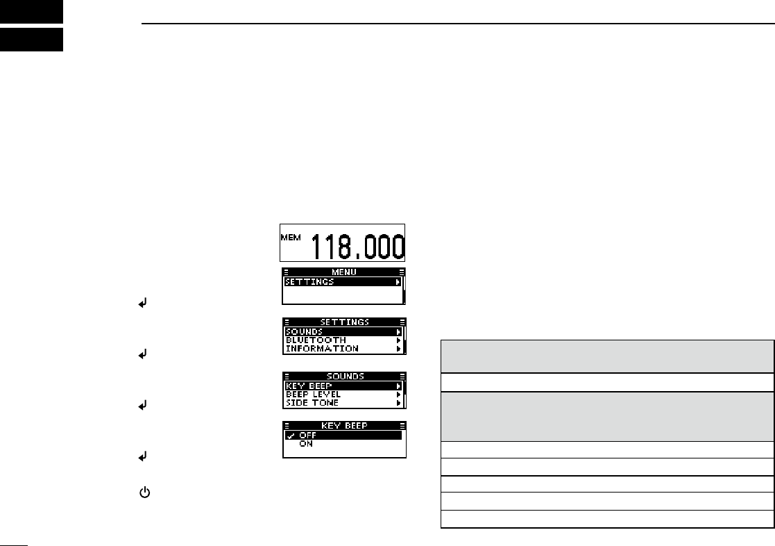
Example: Turning OFF the key beep.
9
4MENU MODE
1) Enter the Menu mode.
➥ Push [MENU/CLR].
2) Open the “SETTINGS” menu.
➥ Push [∫] or [√], and then
push [ /MHz/GRP].
3) Open the “SOUNDS” menu.
➥ Push [∫] or [√], and then
push [ /MHz/GRP].
4) Open the “KEY BEEP” menu.
➥ Push [∫] or [√], and then
push [ /MHz/GRP].
5) Select OFF.
➥ Push [∫] or [√], and then
push [ /MHz/GRP].
6) Exit the Menu mode.
➥ Push [ ].
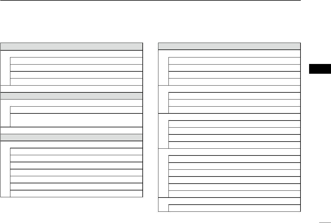
■ Menu item list
The list on this basic manual shows the transceiver’s menu
items.
See the FULL MANUAL for each menu item’s details. You
can download the FULL MANUAL from the Icom website,
shown below.
http://www.icom.co.jp/world/support/download/manual/
index.php
The menu items contained in the transceiver may be
different, depending on the transceiver’s setting. Ask your
dealer or transceiver administrator for details.
VFO MODE/MEMORY MODE group
(For only EXP, USA, and EUR versions.)
VFO MODE/MEMORY MODE
MEMORY WRITE group
(May not be displayed, depending on the transceiver’s
settings.)
MEMORY NAME
LOCKOUT
GROUP
GROUP NAME
WRITE
10
4
MENU MODE
04
MEMORY MANAGE group*1
EDIT
MEMORY NAME
LOCKOUT
GROUP NAME
OVERWRITE
DELETE
BLUETOOTH group*2
PAIR/CONNECT
DEVICE SEARCH
PAIRING LIST
(The paired Bluetooth® headset is displayed.)
PAIRING STANDBY
SETTINGS group
FUNCTIONS
CH SPACING*1
PRIORITY CH*1
NOISE LIMITING
TIME OUT TIMER*1
MIC KEY CUSTOMIZE*1
LOCK FUNCTION
CI-V*1
*1
May not be displayed, depending on the transceiver’s setting.
*2
Displayed only when the optional UT-133A Bluetooth® unit is
installed.
SETTINGS group (Continued)
SCAN*1
SCAN TYPE*1
RESUME TIMER*1
ON-HOOK SCAN*1
STOP/TX CH*1
DISPLAY
LCD BACKLIGHT
LCD CONTRAST
INDICATION TYPE
SOUNDS
KEY BEEP
BEEP LEVEL
SIDE TONE
SPEAKER OUTPUT
BLUETOOTH*2
BLUETOOTH FUNC
AUTO CONNECT*1
HEADSET SET
DATA DEVICE SET*1
DEVICE INFO
DEVICE INITIALIZE*1
INFORMATION
VERSION

11
5SPECIFICATIONS AND OPTIONS
■Specications
DGeneral
• Frequency range:
IC-A120 118.000 to 136.99166 MHz
IC-A120E (AUS version) 118.000 to 136.97500 MHz
IC-A120E (Others) 118.000 to 136.99166 MHz
• Channel spacing: 25 kHz/8.33*1 kHz
• Type of emission:
IC-A120 6K00A3E/5K60A3E (FCC/EXP)
6K00A3E (Industry Canada)
IC-A120E 6K80A3E/5K00A3E*1
• Number of memory channels: 200
• Antenna impedance: 50 ø (nominal)
• Antenna connector: SO-239
• Power supply requirement: 13.75 V/27.5 V DC
(negative ground)
• Current drain (at 13.75 V):
TX 5.0 A
Maximum audio 4.0 A
• Operating temperature range:
IC-A120 –30˚C to +60˚C,
–22˚F to +140˚F
IC-A120E (AUS version) –10˚C to +60˚C
IC-A120E (Others) –20˚C to +55˚C
• Dimensions:
(projections not included)
161 (W)✕45 (H)✕175 (D) mm,
6.3 (W)✕1.8 (H)✕6.9 (D) inches
• Weight (approximately): 1.5 kg, 3.3 lb
DTransmitter
• Output power:
IC-A120 9 W (Carrier power) typical
IC-A120E 9 W±1.5 dB
(+15˚C to +35˚C)
9 W+1.5 dB/–3dB
(–20˚C to +55˚C)
• Frequency stability:
IC-A120 ±5 ppm
(–30˚C to +60˚C, –22˚F to +140˚F)
IC-A120E ±1 ppm (0˚C to +40˚C)
• Modulation system: Last stage modulations
• Audio frequency distortion:
IC-A120 Less than 10%
(at 70% modulation)
IC-A120E Less than 10%
(at 85% modulation +3 dB)
*1 Except IC-A120E (AUS version).
In Canada, use of 8.33 kHz Channel Spacing of this radio is strictly prohibited and shall not be used.

• Spurious emissions:
IC-A120 Less than –60 dBc
IC-A120E*2
9 kHz to 30 MHz Less than –46 dBm
30 MHz to 1 GHz Less than –36 dBm
(For Harmonics)
Less than –46 dBm
(For Non-Harmonics)
1 GHz to 4 GHz Less than –30 dBm
(For Harmonics)
Less than –40 dBm
(For Non-Harmonics)
DReceiver
• Receive system: Double conversion
superheterodyne
• Intermediate frequencies: 1st 38.85 MHz
2nd 450 kHz
• Sensitivity:
IC-A120 Less than 1 μV (pd)
(at 6 dB S/N)
IC-A120E Less than –101 dBm
(12 dB SINAD with CCITT)
• Squelch sensitivity:
IC-A120 Less than 0.35 μV (pd)
IC-A120E Less than –116 dBm
• Spurious response rejection ratio:
IC-A120 More than 5 mV (pd)
IC-A120E More than 70 dB
12
5
SPECIFICATIONS AND OPTIONS
05
Approved Icom optional equipment is designed for optimal
performance when used with an Icom transceiver.
Icom is not responsible for the destruction or damage to an
Icom transceiver in the event the Icom transceiver is used
with equipment that is not manufactured or approved by
Icom.
• Audio output power:
External speaker More than 10 W
(at 13.75 V DC with 8 Ω load 60% mod, 10%
distortion)
Side tone More than 100 mW
(at 13.75 V DC with 500 Ω load 60% mod,
10% distortion)
■Options
HM-217
speaker micrOphOne
The speaker microphone with [∫]/[√] keys and [P1]/[P2]
keys.
VS-3 Bluetooth®
headset
The Bluetooth® headset with a [PTT] switch.
UT-133A Bluetooth®
unit
OPC-871A headset adapter
The adapter to connect a standard headset.
All stated specications are subject to change without
notice or obligation.
*2 Except for operating frequency ±1 MHz.
13
6INFORMATION
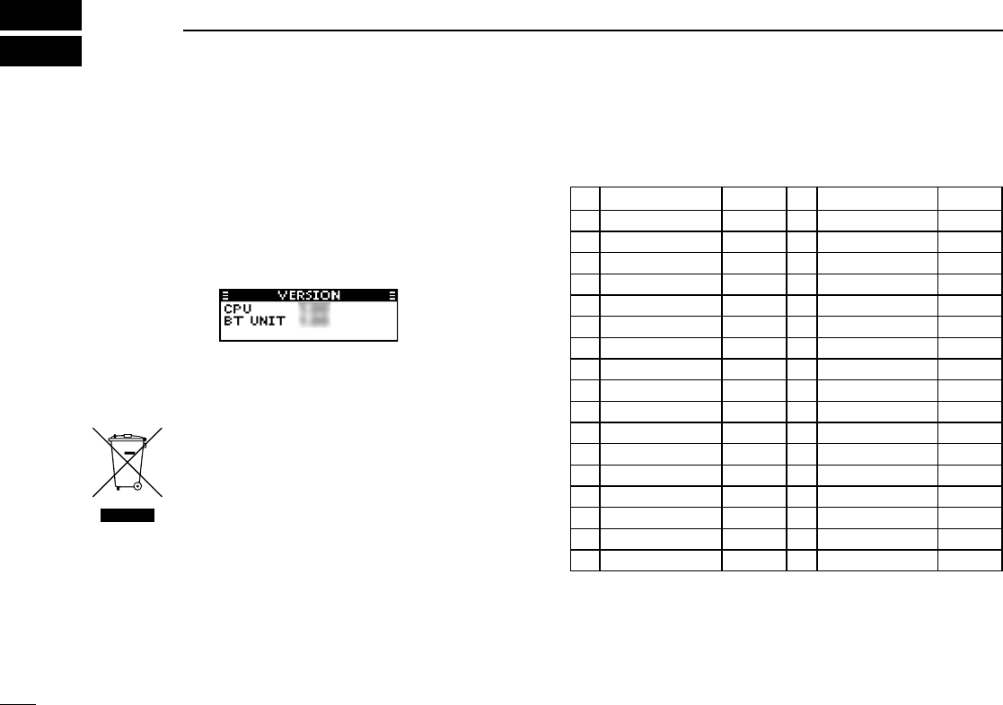
■ Firmware version
identication
You can identify your transceiver’s rmware version in the
“VERSION” menu.
■Disposal
MENU > SETTINGS > INFORMATION > VERSION
■Country code list
• ISO 3166-1
The crossed-out wheeled-bin symbol on your
product, literature, or packaging reminds you
that in the European Union, all electrical and
electronic products, batteries, and accumulators
(rechargeable batteries) must be taken to
designated collection locations at the end of their working
life. Do not dispose of these products as unsorted municipal
waste. Dispose of them according to the laws in your area.
Country Codes Country Codes
1 Austria AT 18 Liechtenstein LI
2 Belgium BE 19 Lithuania LT
3 Bulgaria BG 20 Luxembourg LU
4 Croatia HR 21 Malta MT
5Czech Republic CZ 22 Netherlands NL
6 Cyprus CY 23 Norway NO
7 Denmark DK 24 Poland PL
8 Estonia EE 25 Portugal PT
9 Finland FI 26 Romania RO
10 France FR 27 Slovakia SK
11 Germany DE 28 Slovenia SI
12 Greece GR 29 Spain ES
13 Hungary HU 30 Sweden SE
14 Iceland IS 31 Switzerland CH
15 Ireland IE 32 Turkey TR
16 Italy IT 33 United Kingdom GB
17 Latvia LV
14
6
INFORMATION
1
2
3
4
5
06
7
8
9
0
2
3
4
5
6
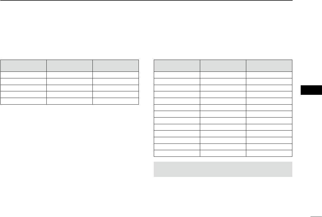
■ VFO channel ID list
• Channel spacing: 25 kHz (Actual frequency is displayed.)
Operating Frequency
(MHz)
Channel spacing
(kHz)
Channel ID
(Displayed Frequency)
118.0000 25 118.000
118.0250 25 118.025
118.0500 25 118.050
118.0750 25 118.075
118.1000 25 118.100
These tables show just the display example between 118.0000 MHz
and 118.1000 MHz. Not all frequencies in the band are shown.
• Channel spacing: 8.33 kHz
Operating Frequency
(MHz)
Channel spacing
(kHz)
Channel ID
(Displayed Frequency)
118.0000 8.33 118.005
118.0083 8.33 118.010
118.0167 8.33 118.015
118.0250 8.33 118.030
118.0333 8.33 118.035
118.0417 8.33 118.040
118.0500 8.33 118.055
118.0583 8.33 118.060
118.0667 8.33 118.065
118.0750 8.33 118.080
118.0833 8.33 118.085
118.0917 8.33 118.090
118.1000 8.33 118.105
(For only EXP, USA, and EUR versions.)
CAUTION: Use of 8.33 kHz Channel Spacing of this radio
is strictly prohibited and shall not be used in Canada.

15
6INFORMATION
■FCC information
• FOR CLASS A UNINTENTIONAL RADIATORS:
This equipment has been tested and found to comply with
the limits for a Class A digital device, pursuant to part 15
of the FCC Rules. These limits are designed to provide
reasonable protection against harmful interference when the
equipment is operated in a commercial environment. This
equipment generates, uses, and can radiate radio frequency
energy and, if not installed and used in accordance with the
instruction manual, may cause harmful interference to radio
communications. Operation of this equipment in a residential
area is likely to cause harmful interference in which case the
user will be required to correct the interference at his own
expense.
• POUR LES RAYONNEMENTS NON INTENTIONNELS
DE CLASSE A:
Cet équipement a été testé et reconnu conforme aux
limites xées pour un appareil numérique de classe A,
conformément au point 15 de la réglementation FCC.
Ces limites sont dénies de façon à fournir une protection
raisonnable contre le brouillage préjudiciable lorsque cet
appareil est utilisé dans un environnement commercial. Cet
équipement génère, utilise et peut émettre un rayonnement
de fréquence radio. S'il n'a pas été installé conformément
aux instructions, il peut par ailleurs créer des interférences
perturbant les communications radio.
L'utilisation de cet appareil dans une zone résidentielle peut
provoquer un brouillage préjudiciable, auquel cas l'utilisateur
sera tenu de corriger la situation à ses frais.

16
INDEX
10
11
12
13
14
15
16
R
Receiving .............................................................................. 4
S
Safety training information ................................................... iv
Specifications .....................................................................11
Squelch .................................................................................5
T
Transmitting ..........................................................................4
Turning ON the transceiver ................................................... 3
V
VFO channel ID list .............................................................14
A
AF Output setting ..................................................................7
B
Basic operation ..................................................................... 3
Bluetooth® operation .............................................................6
D
Disposal .............................................................................. 13
E
Electromagnetic Interference ................................................6
F
FCC information .................................................................15
Firmware version identification ...........................................13
Front panel............................................................................1
Function display ....................................................................2
H
Headset
Disconnecting from a headset .........................................8
Pairing with a headset .....................................................7
Unpairing a headset ........................................................8
I
Important ...............................................................................i
M
Menu item list .......................................................................9
Menu mode ...........................................................................9
O
Options ...............................................................................12
P
Panel Description .................................................................1
Precautions ........................................................................... ii
A-7249D-1EX-q
Printed in Japan
© 2015 Icom Inc.
Printed on recycled paper with soy ink. 1-1-32 Kamiminami, Hirano-ku, Osaka 547-0003, Japan