ICOM orporated 372300 VHF Marine Transceiver User Manual IC M25 EURO 0 indd
ICOM Incorporated VHF Marine Transceiver IC M25 EURO 0 indd
UserManual.wiki
>
ICOM orporated
>
372300 User Manual
User Manual
Navigation menu
Upload a User Manual
Namespaces
Wiki Guide
HTML
PDF
Info
Views
User Manual
Discussion / Help
Navigation
![iiIN CASE OF EMERGENCY RECOMMENDATIONIf your vessel requires assistance, contact other vessels and the Coast Guard by sending a distress call on Channel 16.MUSING CHANNEL 16DISTRESS CALL PROCEDURE1. “MAYDAY MAYDAY MAYDAY.”2. “THIS IS ……………… ” (name of vessel)3. Your call sign or other indication of the ves-sel.4. “LOCATED AT …………… ” (your position)5. The nature of the distress and assistance required.6. Any other information which might facilitate the rescue.CLEAN THE TRANSCEIVER THOROUGHLY WITH FRESH WATER after exposure to saltwater, and dry it before operat-ing. Otherwise, the transceiver's keys, switches and control-lers may become unusable due to salt crystallization.NOTE: DO NOT submerge the transceiver in water if there is any reason to suspect the waterproof protection may not be effective. For example, in cases where the [SP/MIC] jack cap or [DC] connector cover seal is damaged, the transceiver/[DC] connector cover is cracked or broken, or the transceiver has been dropped, or when the antenna or DC connector cover is detached from the transceiver.](https://usermanual.wiki/ICOM-orporated/372300/User-Guide-2622116-Page-3.png)
![vRWARNING! NEVER connect the transceiver to an AC outlet. This may pose a fire hazard or result in an electric shock.RWARNING! NEVER hold the transceiver so that the antenna is closer than 2.5 cm (1 inch) from exposed parts of the body, especially the face or eyes, while transmit-ting. The transceiver will perform best if the microphone is 5 to 10 cm (2 to 4 inches) away from the lips and the trans-ceiver is vertical.CAUTION: NEVER connect the transceiver to a power source more than 5 V DC (1 A). Such a connection will ruin the transceiver.DO NOT use or place the transceiver in direct sunlight or in areas with temperatures below –20°C (–4°F) or above +60°C (+140°F).KEEP the transceiver out of the reach of children.KEEP THETRANSCEIVERATLEASTMETERSFTAWAYfrom your vessel’s magnetic navigation compass.BE CAREFUL! The transceiver meets IPX7* require-ments for waterproof protection. However, once the trans-ceiver has been dropped, waterproof protection cannot be guaranteed because of possible damage to the transceiver's case or the waterproof seal.* Only when the flexible antenna, [DC] cover and [SP/MIC] jack cap are securely attached.MAKE SURE the antenna is securely attached to the transceiver, and that the antenna is dry before attachment. Exposing the inside of the transceiver to water will result in serious damage to the transceiver.Icom, Icom Inc. and Icom logo are registered trademarks of Icom Incorporated(Japan) in Japan, the United States, the United Kingdom, Germany, France,Spain, Russia, Australia, New Zealand, and/or other countries.PRECAUTIONS](https://usermanual.wiki/ICOM-orporated/372300/User-Guide-2622116-Page-6.png)
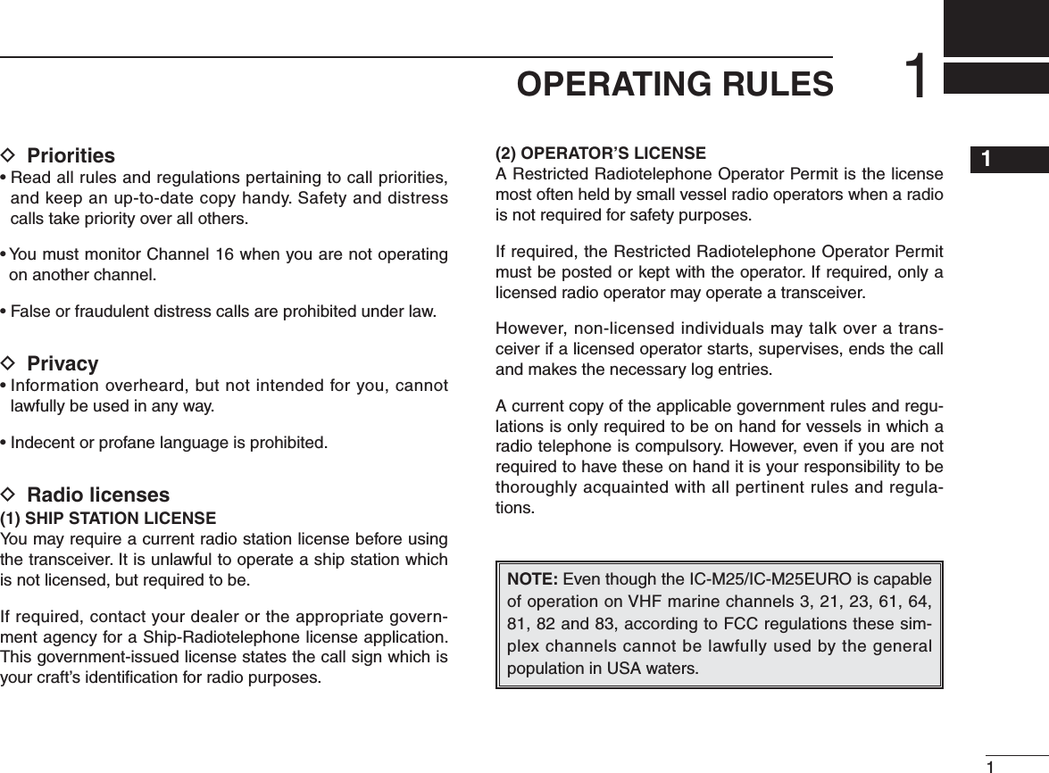
![N ChargerIMPORTANT: Prior to use the transceiver for the first time, fully charge the battery for optimum life and opera-tion. To avoid damage to the battery, turn OFF the power while charging.D Chargingq Turn OFF the power.w Connect the charger as shown below.sThe battery icon scrolls while charging. e The charging is completed in approximately 3 hours, de-pending on the remaining capacity before charging.D Charging from other than supplied charger32SUPPLIED ACCESSORIES AND ATTACHMENTS12345678910111213141516Charger[DC] connectorPower OFFrtUSB to Micro-B USB cable (purchase separatelly)*Some PCs may not supply the required voltage and current.External batteryAC power converterCigarret lighter socket with power converter*5 V, 1 A must be guaranteed.](https://usermanual.wiki/ICOM-orporated/372300/User-Guide-2622116-Page-11.png)
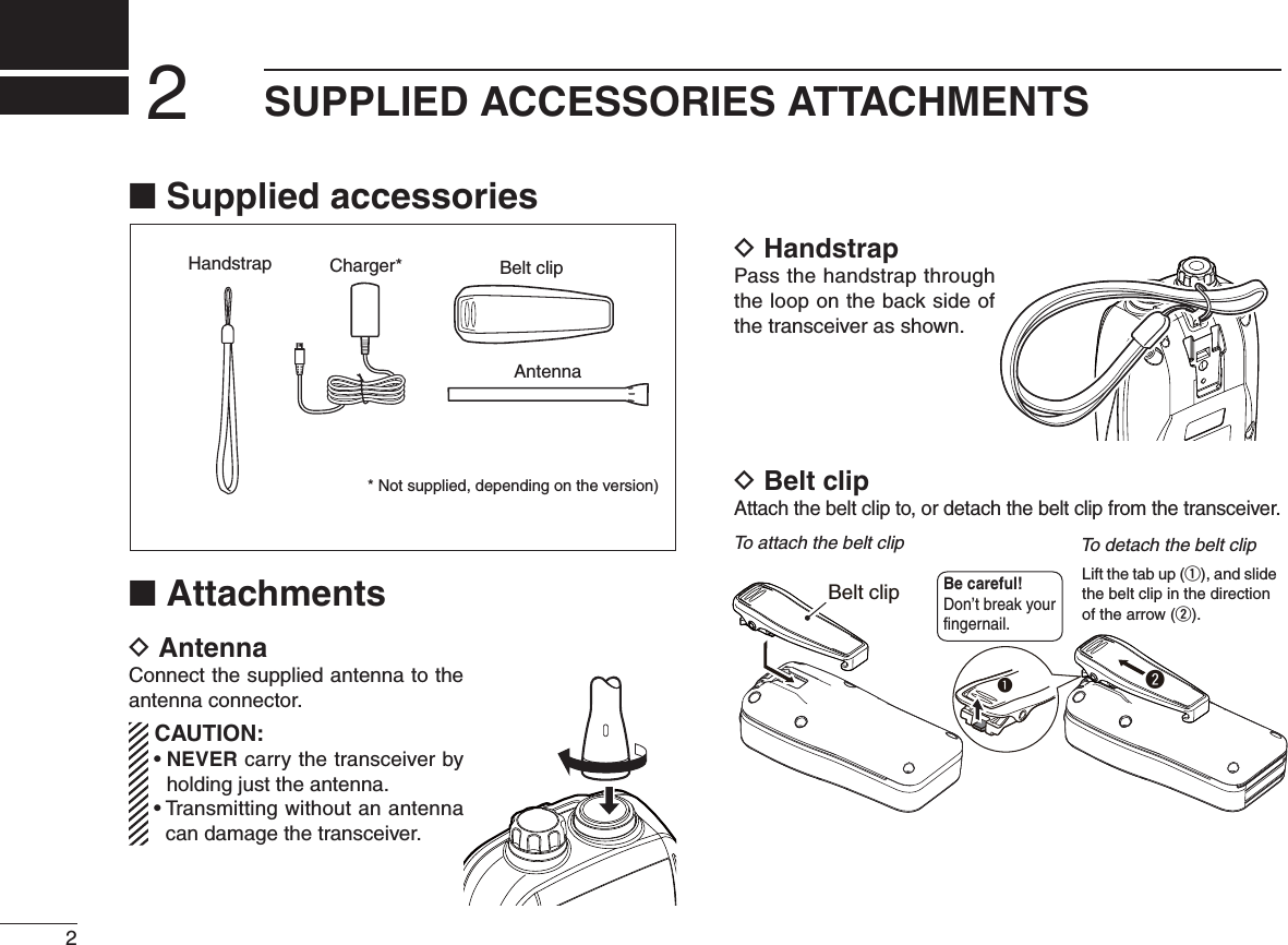
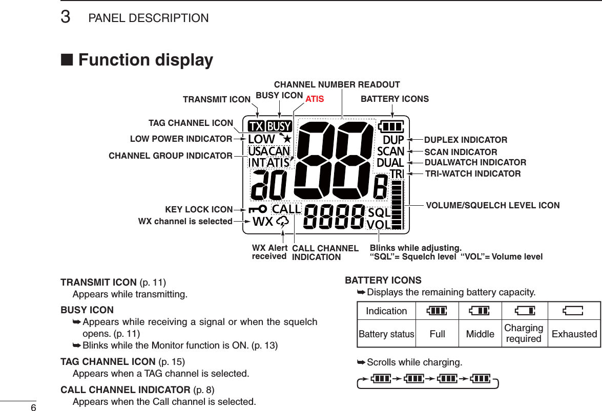
![4PANEL DESCRIPTION3ANTENNA CONNECTOR (p. 2) Connect the supplied antenna.SPEAKER/MIC JACK [SP/MIC] (p. 23) Connect the optional speaker microphone (HM-213) here.PTT SWITCH [PTT] Hold down to transmit: release to receive. (p. 11)POWER KEY [ ] Hold down to turn power ON or OFF.CHANNEL 16 KEY [16 9]±0USHTOSELECT#HANNELP± (OLDDOWNFORSECONDTOSELECTTHE#ALLCHANNELPFunction display SpeakerSCANVOL/SQL[16/9]PTTPWR SWICH[UP/DWN][SP/MIC] JACKAntenna connector[CH/WX]*[FAV][Hi/Lo]Microphone DC JACK4Close up firmly when no cable is conencted.4Make sure dust or other material does not adhere to the seal. Otherwise, waterproof protection may not be guaranteed.1) Rotate the cap counter clockwise. 2) Pull the cap up to detach it.N Nomenclature and main functions](https://usermanual.wiki/ICOM-orporated/372300/User-Guide-2622116-Page-12.png)
![VOLUME/SQUELCH/MONITOR KEY [VOL/SQL MONI] ± Push when you adjust the volume level. While the "VOL" icon blinking, push [UP]/[DWN] to adjust the vol-ume level. The Volume Mute function: ± While holding down this key, push [Z] to temporary maximize the volume level. Do the same operation again to turn OFF the function. The Volume Loud function: ± While holding down this key, push [Y] to temporary mute the audio output. Do the same operation again to turn OFF the function.SCAN/DUAL KEY [SCAN DUAL] ± Push to start or stop a normal or priority scan. (p. 15) ± Hold down for 1 second to enter the Dual/Tri-watch mode. (p. 16) ± Hold down this key and [Hi/Lo] for 1 second, to activate the AquaQuake function. (p. 13)CHARGING CONNECTOR Connect the supplied charger.UP/DOWN KEYS [Y] or [Z]±0USHTOSELECTANOPERATINGCHANNELPPFAVORITE/TAG KEY [FAV TAG]± Push to sequentially select the favorite (TAG) channels SKIPPINGUNTAGGEDCHANNELSP± Hold down for 1 second to set or clear the selected channel as the TAG channel. (p. 15) CHANNEL/WEATHER CHANNEL KEY [CH/WX U/I/C]± Push to switch between a regular channel and a WEATHERCHANNELP± Hold down for 1 second to select the channel group FROM53!)NTERNATIONALAND#ANADAPTRANSMIT POWER/LOCK KEY [Hi/Lo ]± Push to select the output power from high and low. (p. 11)± Hold down for 1 second to lock the key.53PANEL DESCRIPTION12345678910111213141516](https://usermanual.wiki/ICOM-orporated/372300/User-Guide-2622116-Page-13.png)
![BASIC OPERATION4N Selecting channelChoose the appropriate channel groups for your operating area, and then select the channel.D Selecting channel group4 HETRANSCEIVERISPREPROGRAMMEDWITH53!)NTERNA-tional and 65 Canadian channels. ± Hold down [U/I/C] (CH/WX) for 1 second to change the channel group. Repeat to advance to the next group.D Selecting regular channel±Push [Y] or [Z] to select a channel.shDUP” appears for duplex channels. sh!vAPPEARSWHENASIMPLEXCHANNELISSELECTED](https://usermanual.wiki/ICOM-orporated/372300/User-Guide-2622116-Page-16.png)
![D Channel 16Channel 16 is the distress and safety channel. It is used for establishing initial contact with a station, and for emergency communications. While in the standby mode, you must moni-tor Channel 16.q Push [16] momentarily to select Channel 16.w Push [CH/WX] to recall the channel, displayed before se-lecting Channel 16. D Channel 9 (Call channel)#HANNELISALEISUREUSE#ALLCHANNEL%ACHCHANNELGROUPhas a Call channel.q Hold down [9] (16) for 1 second to select the Call channel of the selected channel group.shCALL” and the Call channel number appear.w Push [CH/WX] to recall the channel displayed before select-ing Channel 16.D Weather channelsThe transceiver has 10 weather channels. These are used for monitoring broadcasts from NOAA (National Oceanic and Atmospheric Administration).The transceiver can automatically detect a weather alert tone on the selected weather channel while receiving an-OTHERCHANNELORDURINGASCANPq Push [CH/WX] once or twice to select the Weather chan-nel group.shWX” appears when a weather channel is selected.w Push [Y] or [Z] to select a weather channel.4"!3)#/0%2!4 )/.12345678910111213141516](https://usermanual.wiki/ICOM-orporated/372300/User-Guide-2622116-Page-17.png)
![104"!3)#/0%2!4 )/.N Receiving and transmittingCAUTION: Transmitting without an antenna can damage the transceiver.q Push [Y] or [Z] to select the channel.s7 HENASIGNALISRECEIVEDh ” appears.w Hold down [PTT], and then speak into the microphone.sh ” appears while transmitting.e Release [PTT] to receive.IMPORTANT: To maximize the readability of your trans-mitted signal, pause for a second after pushing [PTT], hold the microphone 5 to 10 cm (2 to 4 inches) from your mouth and speak into the microphone at a normal voice level.For U.S.A version: To prevent prolonged transmission, a time-out timer cuts OFF after 5 minutes of continuous transmission.N Adjusting the volume levelYou can adjust the volume level while the “VOL” icon is blinking.q Push [VOL/SQL] once. s4 HEhVOL” icon starts blinking. s)FNOKEYOPERATIONISPERFORMEDFORSECONDSTHETRANSCEIVERreturns to the normal mode. w Push [Y] or [Z] to adjust the volume level.s4 HELEVELISDISPLAYEDONTHESCREENe Push [VOL/SQL] twice. s2ETURNSTOTHENORMALOPERATINGMODE4) Release to receive.1) Select a channel.2) Push to transmit.3) Speak into the microphone.](https://usermanual.wiki/ICOM-orporated/372300/User-Guide-2622116-Page-18.png)
![N Adjusting the squelch levelSquelch is a function that allows the audio to be heard only while receiving a signal that is stronger than a set level. You can adjust the squelch threshold level.A higher level blocks weak signals, so you receive only stronger signals. A lower level allows you to hear weak sig-nals including noise.Adjust the squelch level when you want to:sBLOCKWEAKSIGNALSINCLUDINGNOISE3ETTHELEVELHIGHERsHEARWEAKSIGNALSEVENINTHENOISE3ETTHELEVELLOWERYou can adjust the squelch level while the “SQL” icon is blinking.q Push [VOL/SQL] twice. s4 HEhSQL” icon starts blinking. s)FNOKEYOPERATIONISPERFORMEDFORSECONDSTHETRANSCEIVERreturns to the normal mode.w Push [Y] or [Z] to adjust the squelch level.s4 HELEVELISDISPLAYEDONTHESCREENe Push [VOL/SQL] once. s2ETURNSTOTHENORMALOPERATINGMODEN Monitor functionThe Monitor function momentary cancels the squelch func-tion. You can check for weak signals including noise.± Hold down [MONI] (VOL/SQL).sh ” blinks. s)FTHEREISAWEAKSIGNALYOUCANHEARTHESIGNALANDNOISE sRelease [MONI] (VOL/SQL) to return the normal squelch mode.NOTE: This function has options. See page ?? for more.N Toggling the transmit power If you receive no response to your call, your transmit signal might not be reached to your callee. Choose high power (5 W: default) for longer distance communications.On the other hand, transmitting at low power is enough to commu-nicate, according to the distance. Choose low power (1 W) for short range and battery conservation.±Push [Hi/Lo] to toggle the transmit power between low and high.shLOW” is displayed when low power is selected. When high power is selected, no icon is displayed. NOTE: s3OMECHANNELSARERESTRICTEDTOLOWPOWERsYou cannot transmit on Channel 70. 114"!3)#/0%2!4 )/.12345678910111213141516](https://usermanual.wiki/ICOM-orporated/372300/User-Guide-2622116-Page-19.png)
![124"!3)#/0%2!4 )/.N Volume Loud functionYou can temporary maximize the volume level with a simple operation.q While holding down [VOL/SQL], push [Y]. s4 HEVOLUMELEVELISSETTOTHEMAXIMUMLEVELs4 HEBARSOFTHEVOLUMELEVELICONREPEATEDLYAPPEARINASCEND-ing order.w Push [VOL/SQL] and [Y] again to turn OFF the function.N Volume Mute functionYou can temporary mute the audio output with a simple op-eration.q While holding down [VOL/SQL], push [Z]. s4 HEVOLUMELEVELISSETTOTHEMINIMUMLEVEL/&& s4 HEBARSOFTHEVOLUMELEVELICONBLINKw Push [VOL/SQL] and [Z] again to turn OFF the function.N Lock functionThis function electronically locks the keys to prevent acci-dental changing of the channel and function access.± Hold down [ ] (Hi/Lo) for 1 second to turn the function ON and OFF. NOTE: [PTT], [VOL/SQL], [MONI] (VOL/SQL), [ ] (Hi/Lo) and [Y] or [Z]* are not locked. * Only while the adjusting the volume or squelch, and volume loud and Volume Mute functions.N AquaQuake Water Draining functionWater in the speaker grill may muffle the sound coming from the speaker. The AquaQuake Water Draining function removes water from the speaker grill, by generating vibrating sound.± Hold down both [SCAN] and [Hi/Lo]. s!LOWVIBRATIONTONESOUNDSFORSECONDSTODRAINWATERRE-gardless of the volume level setting.s4 HETRANSCEIVERDOESNOTACCEPTANYKEYOPERATIONSWHILETHISfunction is activated.](https://usermanual.wiki/ICOM-orporated/372300/User-Guide-2622116-Page-20.png)
![134"!3)#/0%2!4 )/.12345678910111213141516N Setting TAG channelsYou can quickly recall often-used channels by tagging them as TAG channels. TAG channels can be independently assigned to each chan-nel group (USA, International and Canada).q Hold down [U/I/C] (CH/WX) for 1 second to change the channel group, if needed. Repeat to go to the next group.w Select the desired channel you want to set as a TAG channel.e Hold down [*] (FAV) for 1 second. s4 HEDISPLAYEDCHANNELISSETASA4 !' CHANNELsh ” appears on the display.To select a TAG channel:± Push [FAV] (*) several times to select the desired TAG channel. s.ON4 !' channels are skipped.To clear a TAG channel:q Select the desired channel you wan to clear the tagging.w Hold down [*] (FAV) for 1 second.sh ” disappears.To clear all TAG channels:± While holding down [*] (FAV), turn ON the power. s!LL4 !' CHANNELSINTHESELECTEDCHANNELGROUPARECLEAREDN Setting the Call channelYou can recall the most often-used channel with a single op-eration, by setting the channel as a Call channel.A Call channel can be set in each channel group.q Hold down [U/I/C] (CH/WX) for 1 second to change the channel group. Repeat to go to the next group.w Hold down [9] (16) for 1 second to recall the current Call channel in the selected group.shCALL” and the Call channel number appear.e Hold down [9] (16) again for 3 seconds (until a long beep changes to 2 short beeps) to enter the Call channel set-ting mode.s4 HECHANNELNUMBERSTARTSBLINKINGr Push [Y] or [Z] to select the new Call channel.t Push [9] (16) to set.s4 HECHANNELNUMBERSTOPSBLINKING](https://usermanual.wiki/ICOM-orporated/372300/User-Guide-2622116-Page-21.png)
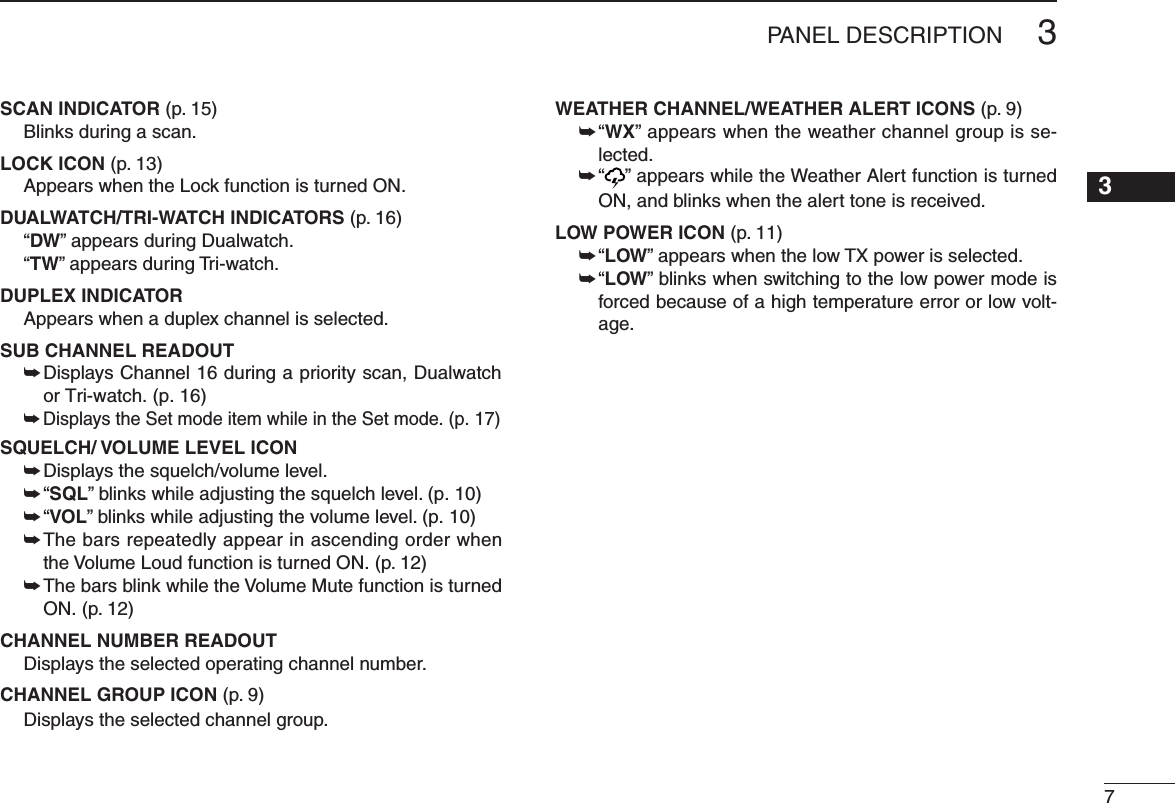
![N Start to scanq Hold down [U/I/C] (CH/WX) for 1 second one or more times to select a desired channel group.s7 HENTHE7 EATHER!LERTFUNCTIONISINUSESELECTADESIREDweather channel using [CH/WX] and [Y] or [Z].w Push [SCAN] to start a scan.shSCAN” blinks while scanning. shvAPPEARSONTHESUBCHANNELREADOUTDURINGAPRIORITYSCANs7 HENASIGNALISRECEIVEDTHESCANPAUSESUNTILTHESIGNALdisappears, or resumes after pausing 5 seconds, depending on the Set mode setting. e To stop the scan, push [SCAN] again.shSCAN” disappears. s0USHING[PTT], [16], [CH/WX] or [FAV] also stops the scan.155SCAN OPERATION12345678910111213141516](https://usermanual.wiki/ICOM-orporated/372300/User-Guide-2622116-Page-23.png)
![16DUALWATCH AND TRI-WATCH6N DescriptionDualwatch/Tri-watch are convenient for monitoring Channel 16 when you are operating on another channel. Dualwatch monitors Channel 16 while you are receiving on another channel.Tri-watch monitors Channel 16 and Call channel while re-ceiving on another channel. N Operationq3ELECT$ UALWATCHOR4 RIWATCHINTHE3ETMODEPw Select the desired channel.e Hold down [DUAL] (SCAN) for 1 second to start Dual-watch or Tri-watch, depending on the Set mode setting.shDUAL” blinks during Dualwatch. “TRI” blinks during Tri-watch. s!BEEPTONESOUNDSWHENASIGNALISRECEIVEDON#HANNELs4 RIWATCHSWITCHESTO$ UALWATCHWHENRECEIVINGASIGNALONTHECall channel.r To cancel Dualwatch/Tri-watch, push [DUAL] (SCAN) again.s)FASIGNALISRECEIVEDON#HANNEL$ UALWATCH4 RIwatch pauses on Channel 16 until the signal disappears.s)FASIGNALISRECEIVEDONTHE#ALLCHANNELDURING4 RIwatch, Tri-watch becomes Dualwatch until the signal dis-appears.DualwatchDUALWATCH/TRI-WATCH SIMULATIONTri-watchCallchannelCh 88Ch 16 Ch 88 Ch 16 Ch 88 Ch 9](https://usermanual.wiki/ICOM-orporated/372300/User-Guide-2622116-Page-24.png)
![N Set mode programmingThe Set mode is used to select an option for the transceiv-er's functions.D Set mode operationq Turn OFF the power.w While holding down [VOL/SQL], turn ON the power to enter the Set mode. s4 HESTARTINGITEMhB%%0vAPPEARSe While holding down [VOL/SQL], push [Y] or [Z] to select an item.r Push [Y] or [Z] to select an option of the item.t Push [16] to exit the Set mode, .177SET MODE12345678910111213141516](https://usermanual.wiki/ICOM-orporated/372300/User-Guide-2622116-Page-25.png)
![D Auto Scan function “Auto”The Auto Scan function automatically starts a normal or priority scan when no signal is received, and no operation is performed for 30 seconds.D Dual/Tri-watch function “dt”Set the watch type to Dualwatch or Tri-watch. (p. 16)D Monitor key action “SqLS”The monitor key momentary cancels the squelch function. Select a key action option.s0U053( 4 HE-ONITORFUNCTIONISACTIVATEDWHILEHOLDINGDOWN[MONI] (VOL/SQL). The squelch function is can-celed while holding down the key.s(O(/,$ 4 HE-ONITORFUNCTIONISACTIVATEDBYHOLDINGDOWN[MONI] (VOL/SQL) for 1 second. The squelch func-tion is canceled until any key is pushed again.7SET MODE12345678910111213141516](https://usermanual.wiki/ICOM-orporated/372300/User-Guide-2622116-Page-27.png)
![207SET MODED Automatic backlighting “A_bL”This function is convenient for the operation in the night. The backlight can be selected from ON and OFF.s4 HEBACKLIGHTISAUTOMATICALLYACTIVATEDWHENANYKEYEXCEPT[PTT] is pushed.s4 HEBACKLIGHTISAUTOMATICALLYTURNED/&&AFTERSECONDSOFINAC-tivity.D LCD contrast setting “Lcdc”Set the LCD contrast level to High contrast or Low contrast. The LCD contrast level has little effect during indoor use.D Power Save function “P_SA”The Power Save function reduces current drain by periodi-cally turning OFF the receiver circuit. s/&& 4 HEFUNCTIONISTURNED/&&s/. When no signal is received, and no operation is performed for 5 seconds, the Power Save function is activated.D Float Alert function “FLAr”Alert periodically sounds while the radio is floating in the water so that you can noticed that you dropped the radio.s/&& 4 HEFUNCTIONIS/&&s/. Alert periodically sounds while the radio is floating in the water.D Automatic Water Draining function “AquA”This function automatically activates the AquaQuake Water Drain-ing function when the radio has been retrieved from the water.s/&& 4 HEFUNCTIONIS/&&s 4 HE!QUA1UAKE7 ATER$ RAININGFUNCTIONISAUTOMATICALLYactivated and A low vibration tone sounds for the specified time period (2, 5 or 10 seconds).](https://usermanual.wiki/ICOM-orporated/372300/User-Guide-2622116-Page-28.png)
![22N HM-213 descriptionsA speaker microphone is light weight and fits in your palm and allows you to talk and listen more easier. The HM-213 speaker microphone is prepared for the IC-M25/M25EURO.PTT switchTransmits during push.Receives during release.MicrophoneSpeakerAlligator type clipTo attach the speaker-mic.to your shirt or collar, and so on.Turn the transceiver power OFF when connecting the HM-213.NEVER immerse the connector in water. If the connector GETSWETBESURETODRYIT"%&/2%ATTACHINGITTOTHETRANS-ceiver.NOTE: The microphone is located at the top of the speaker-microphone, as shown above. To maximize the readability of your transmitted signal (voice), hold the mi-crophone approx. 5 to 10 cm (2 to 4 inches) from your mouth, and speak in a normal voice level.N AttachmentTurn OFF the power. Then, insert the speaker-mic connector into the [SP MIC] connector and carefully screw it tight, as SHOWNBELOW"ECAREFULNOTTOCROSSTHREADTHECONNECTIONCAUTION: Attach the speaker-microphone’s connector securely to prevent accidental loss, or water intrusion in the connector.Detaching:Rotate the [SP MIC] cap counter-clockwise (1), then detach it (2).Attaching:Attach the [SP MIC] cap (1), then rotate it clockwise completely (2).1221 IMPORTANT: KEEP the transceiver’s [SP MIC] cap attached when the speaker-microphone is not in use. If the cover is not attached, water will get into the transceiver. Moreover, the terminals (pins) will become rusty, or the transceiver will function abnormally if the connector gets wet.OPTIONAL SPEAKER-MICROPHONE](https://usermanual.wiki/ICOM-orporated/372300/User-Guide-2622116-Page-30.png)
![2310TROUBLESHOOTING12345678910111213141516PROBLEM POSSIBLE CAUSE SOLUTIONThe transceiver does not turn ON.s4 HEBATTERYISEXHAUSTED s#HARGETHEBATTERYNo sound from speaker. s4 HESQUELCHLEVELISTOOHIGHs6 OLUMELEVELISTOOLOWs3PEAKERHASBEENEXPOSEDTOWATERs3ETTHEsquelch level to the threshold level.s!DJUSTTHEAUDIOLEVELTOASUITABLELEVELs2EMOVEWATERFROMTHESPEAKERGRILLTransmitting is impossible, or high power can not be se-lected.s3OMECHANNELSARELIMITEDTOLOWPOWERor only receive.s4 HEOUTPUTPOWERISSETTOLOWs4 HEBATTERYISEXHAUSTEDs#HANGETHECHANNELs0USH[Hi/Lo] to select high power.s2ECHARGETHEBATTERYPACKThe displayed channel cannot be changed.s4 HE,OCKFUNCTIONISACTIVATED s(OLDDOWN[] (Hi/Lo) for 1 second to turn OFF the function.Scan does not start sh4 !' vCHANNELSARENOTPROGRAMMED sSet desired channels as “TAG” channels.No beep sounds. s"EEP4 ONEFUNCTIONISTURNED/&& s4 URN/.THE"EEP4 ONEINTHESETMODE](https://usermanual.wiki/ICOM-orporated/372300/User-Guide-2622116-Page-31.png)