ICOM orporated 372300 VHF Marine Transceiver User Manual IC M25 EURO 0 indd
ICOM Incorporated VHF Marine Transceiver IC M25 EURO 0 indd
User Manual

INSTRUCTION MANUAL
iM25EURO
iM25
VHF MARINE TRANSCEIVER
This device complies with Part 15 of the FCC
Rules. Operation is subject to the condition that
this device does not cause harmful interference.
ii
FOREWORD
Thank you for purchasing this Icom radio. The IC-M25/IC-
M25EURO VHF
MARINE TRANSCEIVER is designed and built
with Icom’s state of the art technology and craftsmanship.
With proper care this radio should provide you with years of
trouble-free operation.
IMPORTANT
READ ALL INSTRUCTIONS carefully and com-
pletely before using the transceiver.
SAVE THIS INSTRUCTION MANUAL—This
instruction manual contains important operating instructions
for the IC-M25/IC-M25EURO.
EXPLICIT DEFINITIONS
WORD DEFINITION
RDANGER! Personal death, serious injury or an explo-
sion may occur.
RWARNING! Personal injury, fire hazard or electric
shock may occur.
CAUTION Equipment damage may occur.
NOTE
If disregarded, only inconvenience. No risk
of personal injury, fire or electric shock.
FEATURES
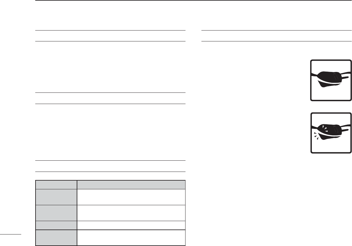
Floats on water
The transceiver floats in fresh or salt
water even when the supplied acces-
sories are attached.
s)TMAYSINKWHENATHIRDPARTYSTRAPAN-
tenna, and so on is attached.
Floats and flashes
An LED sends out intermittent light from
a transparent section on the bottom of
the radio, while floating in the water.
As the LED light stands out in the dark, the
radio can be easily retrieved from the water.
This function works even when the radio is
turned OFF.
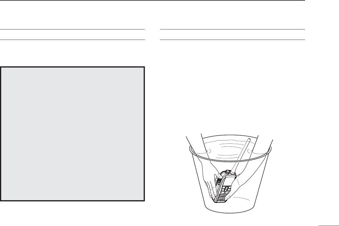
Floats and flashes and alert
An alert sounds when the radio is dropped into the water
so that you can noticed that you dropped the radio.
For Canada:
This device complies with RSS-310 of Industry Canada. Operation is subject
to the condition that this device does not cause harmful interference.
Cet appareil est conforme au CNR-310 d’Industrie Canada. Son exploitation
est autorisée sous réserve que l’appareil ne cause pas de brouillage
préjudiciable.
ii
IN CASE OF EMERGENCY RECOMMENDATION
If your vessel requires assistance, contact other vessels and
the Coast Guard by sending a distress call on Channel 16.
MUSING CHANNEL 16
DISTRESS CALL PROCEDURE
1. “MAYDAY MAYDAY MAYDAY.”
2. “THIS IS ……………… ” (name of vessel)
3. Your call sign or other indication of the ves-
sel.
4. “LOCATED AT …………… ” (your position)
5. The nature of the distress and assistance
required.
6. Any other information which might facilitate
the rescue.
CLEAN THE TRANSCEIVER THOROUGHLY WITH FRESH
WATER after exposure to saltwater, and dry it before operat-
ing. Otherwise, the transceiver's keys, switches and control-
lers may become unusable due to salt crystallization.
NOTE: DO NOT submerge the transceiver in water if there is
any reason to suspect the waterproof protection may not be
effective. For example, in cases where the [SP/MIC] jack cap
or [DC] connector cover seal is damaged, the transceiver/
[DC] connector cover is cracked or broken, or the transceiver
has been dropped, or when the antenna or DC connector
cover is detached from the transceiver.

iii
RADIO OPERATOR WARNING
Your Icom radio generates RF electromagnetic energy dur-
ing transmit mode. This radio is designed for and classified as
“General Population Use” in an uncontrolled environment.
This radio has been evaluated for compliance at the distance
of 2.5 cm (1 inch) with the FCC and IC RF exposure limits for
“
General Population Use.
” In addition, your Icom radio complies
with the following Standards and Guidelines with regard to RF
energy and electromagnetic energy levels and evaluation of
such levels for exposure to humans:
s&##/%4 "ULLETIN%DITION3UPPLEMENT#%VALUATING#OMPLI-
ance with FCC Guidelines for Human Exposure to Radio Frequency
Electromagnetic Fields.
s!MERICAN.ATIONAL3TANDARDS)NSTITUTE#)%%%3TANDARD
for Safety Levels with Respect to Human Exposure to Radio Frequency
Electromagnetic Fields, 3 kHz to 300 GHz.
s!MERICAN.ATIONAL3TANDARDS)NSTITUTE#)%%%2ECOM-
mended Practice for the Measurement of Potentially Hazardous Electro-
magnetic Fields– RF and Microwave.
s4 HEFOLLOWINGACCESSORIESAREAUTHORIZEDFORUSEWITHTHISPRODUCT5SEOF
accessories other than those specified may result in RF exposure levels
exceeding the FCC
and IC
REQUIREMENTSFORWIRELESS2&EXPOSURE"ELT
#LIP-"2ECHARGEABLE,IION"ATTERY0ACK"0
To ensure that your expose to RF electromagnetic energy
is within the FCC
and IC
allowable limits for general popu-
lation use, always adhere to the following guidelines:
sDO NOT operate the radio without a proper antenna attached, as this
may damaged the radio and may also cause you to exceed FCC
and
IC
RF exposure limits. A proper antenna is the antenna supplied with
this radio by the manufacturer or antenna specifically authorized by the
manufacturer for use with this radio.
sDO NOT transmit for more than 50% of total radio use time (“50% duty
cycle”). Transmitting more than 50% of the time can cause FCC
and IC
RF exposure compliance requirements to be exceeded. The radio is
transmitting when the “transmit indicator” appears on the LCD. You can
cause the radio to transmit by pressing the “PTT” switch.
sALWAYS keep the antenna at least 2.5 cm (1 inch) away from the body
when transmitting and only use the Icom belt clip which is listed on page
43 when attaching the radio to your belt, etc., to ensure FCC
and IC
RF
exposure compliance requirements are not exceeded. To provide the re-
cipients of your transmission the best sound quality, hold the antenna at
least 5 cm (2 inches) from your mouth, and slightly off to one side.
The information listed above provides the user with the information needed
to make him or her aware of RF exposure, and what to do to assure that this
radio operates with the FCC
and IC
RF exposure limits of this radio.
Electromagnetic Interference/Compatibility
During transmissions, your Icom radio generates RF energy that can possibly
cause interference with other devices or systems. To avoid such interference,
turn off the radio in areas where signs are posted to do so. DO NOT operate
the transmitter in areas that are sensitive to electromagnetic radiation such as
hospitals, aircraft, and blasting sites.

iv
AVERTISSEMENT POUR LES OPÉRATEURS RADIO
Votre radio Icom produit une énergie électromagnétique
de radiofréquences (RF), en mode de transmission. Elle
est conçue pour une «utilisation grand public», dans un
environnement non contrôlé. Cet appareil a été évalué et
jugé conforme, à 2,5 cm, aux limites d'exposition aux RF
de la FCC et d’IC, pour une «utilisation grand public». En
outre, votre radio Icom satisfait les normes et directives
qui suivent en matière de niveaux d'énergie et d'énergie
électromagnétique de RF et d'évaluation de tels niveaux
en ce qui concerne l'exposition humaine :
s3UPPL£MENT # £DITION DU "ULLETIN /%4 DE LA &## i%VALUATING
Compliance with FCC Guidelines for Human Exposure to Radio Frequency
Electromagnetic Fields».
s.ORME DE L!MERICAN .ATIONAL 3TANDARDS )NSTITUTE !.3) )%%% #
SURLESNIVEAUXDES£CURIT£COMPATIBLESAVECLEXPOSITIONHUMAINEAUX
champs électromagnétiques de radiofréquences (3 kHz à 300 GHz).
s.ORMEDEL!.3))%%%#SURLAM£THODED£VALUATIONRECOMMAN-
dée du champ magnétique potentiellement dangereux des radiofréquences
et des micro-ondes.
s,ES ACCESSOIRES QUI SUIVENT SONT APPROUV£S POUR UNE UTILISATION AVEC CE
produit. L'utilisation d'accessoires autres que ceux précisés peut entraîner
des niveaux d'exposition aux RF supérieures aux limites établies par la FCC
ETD)#ENMATIÞREDgEXPOSITIONAUX2&SANSlLATTACHEPOURCEINTURE-"
BLOCPILESRECHARGEABLEAULITHIUMION"0
CAUTION
Afin de vous assurer que votre exposition à une
énergie électromagnétique de RF se situe dans
les limites permises par la FCC et d’IC pour une
utilisation grand public, veuillez en tout temps
respecter les directives suivantes :
sNE PAS faire fonctionner la radio sans qu'une antenne appropriée y soit
fixée, car ceci risque d'endommager la radio et causer une exposition
supérieure aux limites établies par la FCC et d’IC. L'antenne appropriée
est celle qui est fournie avec cette radio par le fabricant ou une antenne
spécialement autorisée par le fabricant pour être utilisée avec cette radio.
s NE PAS émettre pendant plus de 50% du temps total d'utilisation de
l'appareil («50% du facteur d'utilisation»). Émettre pendant plus de 50% du
temps total d'utilisation peut causer une exposition aux RF supérieure aux
limites établies par la FCC et d’IC. La radio est en train d’émettre lorsque le
témoin du mode de transmission s'affiche sur l'écran ACL. La radio émettra
si vous appuyez sur le bouton du microphone.
s TOUJOURS tenir l'antenne éloignée d'au moins 2,5 cm de votre corps
au moment d'émettre et utiliser uniquement l'attache pour ceinture Icom
illustrée à la p. 43, lorsque vous attachez la radio à votre ceinture, ou à
autre chose, de façon à vous assurer de ne pas provoquer une exposition
aux RF supérieure aux limites fixées par la FCC et d’IC. Pour offrir à vos
interlocuteurs la meilleure qualité de transmission possible, tenez l'antenne
à au moins 5 cm de votre bouche et légèrement de côté.
Les renseignements ci-dessus fournissent à l'utilisateur toute l'information
nécessaire sur l'exposition aux RF et sur ce qu'il faut faire pour assurer que
cette radio fonctionne en respectant les limites d'exposition aux RF établies
par la FCC et d’IC.
Interférence électromagnétique et compatibilité
En mode de transmission, votre radio Icom produit de l'énergie de RF qui
peut provoquer des interférences avec d'autres appareils ou systèmes. Pour
éviter de telles interférences, mettez la radio hors tension dans les secteurs
où une signalisation l’exige. NE PAS faire fonctionner l'émetteur dans des
secteurs sensibles au rayonnement électromagnétique tels que les hôpitaux,
les aéronefs et les sites de dynamitage.
AVERTISSEMENT
MISE EN GARDE

v
RWARNING! NEVER connect the transceiver to an
AC outlet. This may pose a fire hazard or result in an electric
shock.
RWARNING! NEVER hold the transceiver so that
the antenna is closer than 2.5 cm (1 inch) from exposed
parts of the body, especially the face or eyes, while transmit-
ting. The transceiver will perform best if the microphone is
5 to 10 cm (2 to 4 inches) away from the lips and the trans-
ceiver is vertical.
CAUTION: NEVER connect the transceiver to a
power source more than 5 V DC (1 A). Such a connection
will ruin the transceiver.
DO NOT use or place the transceiver in direct sunlight
or in areas with temperatures below –20°C (–4°F) or above
+60°C (+140°F).
KEEP the transceiver out of the reach of children.
KEEP THETRANSCEIVERATLEASTMETERSFTAWAY
from your vessel’s magnetic navigation compass.
BE CAREFUL! The transceiver meets IPX7* require-
ments for waterproof protection. However, once the trans-
ceiver has been dropped, waterproof protection cannot be
guaranteed because of possible damage to the transceiver's
case or the waterproof seal.
* Only when the flexible antenna, [DC] cover and [SP/MIC] jack cap
are securely attached.
MAKE SURE the antenna is securely attached to the
transceiver, and that the antenna is dry before attachment.
Exposing the inside of the transceiver to water will result in
serious damage to the transceiver.
Icom, Icom Inc. and Icom logo are registered trademarks of Icom Incorporated
(Japan) in Japan, the United States, the United Kingdom, Germany, France,
Spain, Russia, Australia, New Zealand, and/or other countries.
PRECAUTIONS

vi
FOREWORD .....................................................................................i
IMPORTANT ...................................................................................... i
EXPLICIT DEFINITIONS ................................................................... i
FEATURES ........................................................................................i
IN CASE OF EMERGENCY ............................................................. ii
RECOMMENDATION ....................................................................... ii
SAFETY TRAINING INFORMATION ............................................... iii
INFORMATION EN MATIÈRE DE SÉCURITÉ ................................ iv
PRECAUTIONS ................................................................................ v
4 !",%/&#/.4 %.4 3 ................................................................... vi
FCC INFORMATION ...................................................................... vii
1 OPERATING RULES ..................................................................1
2 SUPPLIED ACCESSORIES AND ATTACHMENTS ...............2–3
N Supplied accessories ...............................................................2
N Attachments .............................................................................2
3 PANEL DESCRIPTION ...........................................................4–7
N Front, top and side panels .......................................................4
N Function display .......................................................................6
4 BASIC OPERATION .............................................................8–13
N Channel selection ....................................................................
N Adjusting the volume level .....................................................10
N Adjusting the squelch level ....................................................10
N Receiving and transmitting ....................................................11
N Call channel programming .....................................................12
N Volume Loud function ............................................................12
N Volume Mute function ............................................................12
N Lock function ..........................................................................13
N Monitor function .....................................................................13
N Automatic backlighting ...........................................................13
N AquaQuake Water Draining function......................................13
5 SCAN OPERATION ............................................................14–15
N Scan types .............................................................................14
N Setting TAG channels ............................................................15
N Starting a scan .......................................................................15
6 DUALWATCH/TRI-WATCH .......................................................16
N Description .............................................................................16
N Operation ...............................................................................16
7 SET MODE ..........................................................................17–20
N Set mode programming .........................................................17
N Set mode items ......................................................................1
8 BATTERY CHARGING .......................................................21–25
N"ATTERYCAUTION .......................................................................21
N Supplied battery charger .......................................................23
N Optional battery charger ........................................................23
9 TROUBLESHOOTING ..............................................................26
10 VHF MARINE CHANNEL LIST .................................................27
11 SPECIFICATIONS AND OPTIONS ...........................................28
N Specifications.........................................................................2
N Options ..................................................................................2
4 !",%/&#/.4 %.4 3

vii
FOR CLASS A UNINTENTIONAL RADIATORS
This equipment has been tested and found to comply with the
limits for a Class A digital device, pursuant to part 15 of the
FCC Rules. These limits are designed to provide reasonable
protection against harmful interference when the equipment
is operated in a commercial environment. This equipment
generates, uses, and can radiate radio frequency energy
and, if not installed and used in accordance with the instruc-
tion manual, may cause harmful interference to radio commu-
nications. Operation of this equipment in a residential area is
likely to cause harmful interference in which case the user will
be required to correct the interference at his own expense.
CAUTION: Changes or modifications to this device, not ex-
pressly approved by Icom Inc., could void your authority to
operate this device under FCC regulations.
FCC INFORMATION

D Priorities
s2EADALLRULESANDREGULATIONSPERTAININGTOCALLPRIORITIES
and keep an up-to-date copy handy. Safety and distress
calls take priority over all others.
s9OUMUSTMONITOR#HANNELWHENYOUARENOTOPERATING
on another channel.
s&ALSEORFRAUDULENTDISTRESSCALLSAREPROHIBITEDUNDERLAW
D Privacy
s)NFORMATIONOVERHEARDBUTNOTINTENDEDFORYOUCANNOT
lawfully be used in any way.
s)NDECENTORPROFANELANGUAGEISPROHIBITED
D Radio licenses
(1) SHIP STATION LICENSE
You may require a current radio station license before using
the transceiver. It is unlawful to operate a ship station which
is not licensed, but required to be.
If required, contact your dealer or the appropriate govern-
ment agency for a Ship-Radiotelephone license application.
This government-issued license states the call sign which is
your craft’s identification for radio purposes.
(2) OPERATOR’S LICENSE
A Restricted Radiotelephone Operator Permit is the license
most often held by small vessel radio operators when a radio
is not required for safety purposes.
If required, the Restricted Radiotelephone Operator Permit
must be posted or kept with the operator. If required, only a
licensed radio operator may operate a transceiver.
However, non-licensed individuals may talk over a trans-
ceiver if a licensed operator starts, supervises, ends the call
and makes the necessary log entries.
A current copy of the applicable government rules and regu-
lations is only required to be on hand for vessels in which a
radio telephone is compulsory. However, even if you are not
required to have these on hand it is your responsibility to be
thoroughly acquainted with all pertinent rules and regula-
tions.
NOTE: Even though the IC-M25/IC-M25EURO is capable
of operation on VHF marine channels 3, 21, 23, 61, 64,
ANDACCORDINGTO&##REGULATIONSTHESESIM-
plex channels cannot be lawfully used by the general
population in USA waters.
1
1
OPERATING RULES
1
2
3
4
5
6
7
8
9
10
11
12
13
14
15
16
2
SUPPLIED ACCESSORIES ATTACHMENTS
2
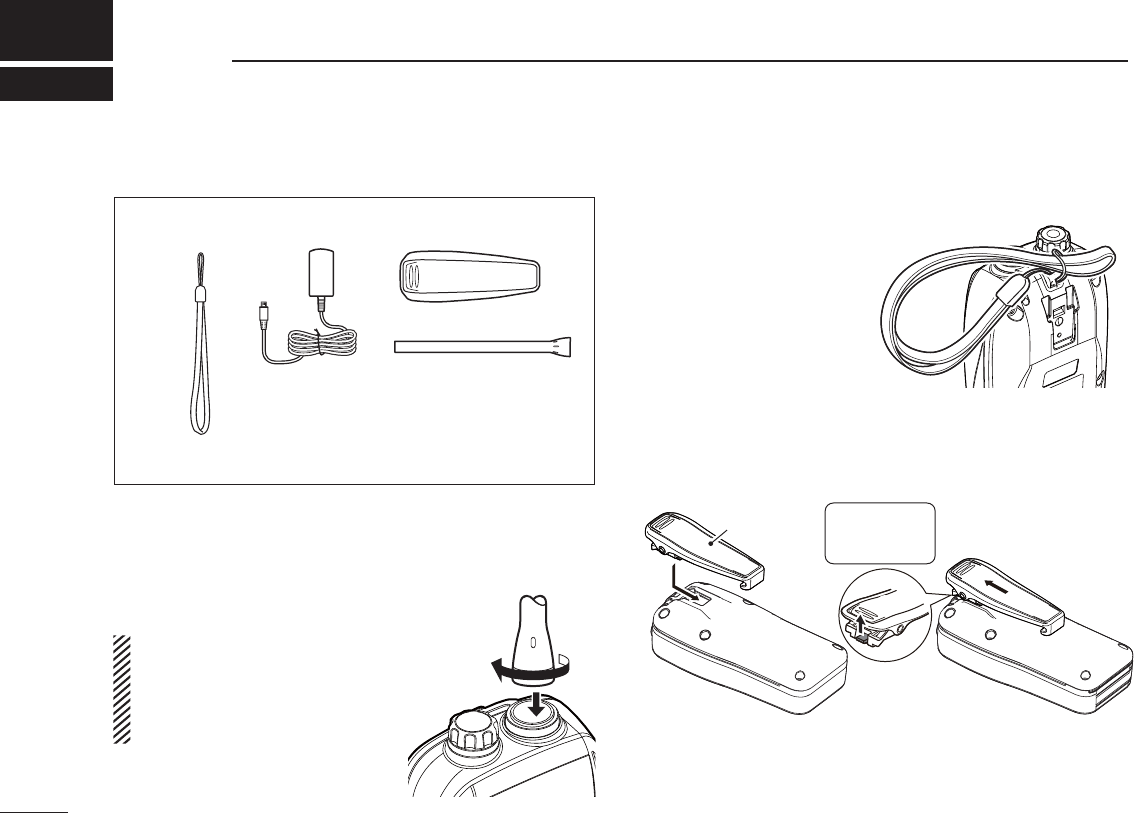
N Supplied accessories
N Attachments
D Antenna
Connect the supplied antenna to the
antenna connector.
CAUTION:
sNEVER carry the transceiver by
holding just the antenna.
s4 RANSMITTINGWITHOUTANANTENNA
can damage the transceiver.
D Handstrap
Pass the handstrap through
the loop on the back side of
the transceiver as shown.
D Belt clip
Attach the belt clip to, or detach the belt clip from the transceiver.
Handstrap Belt clip
Antenna
Charger*
* Not supplied, depending on the version)
To attach the belt clip To detach the belt clip
Be careful!
Don’t break your
fingernail.
q
Belt clip
w
Lift the tab up (q), and slide
the belt clip in the direction
of the arrow (w).
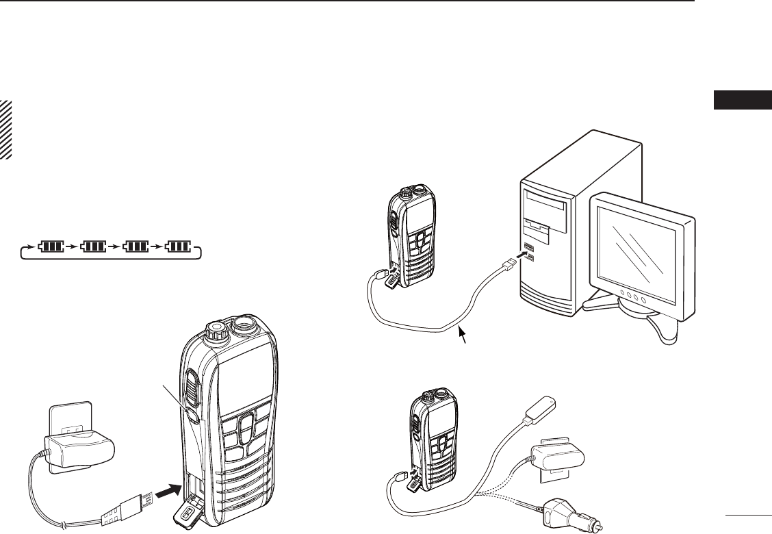
N Charger
IMPORTANT: Prior to use the transceiver for the first
time, fully charge the battery for optimum life and opera-
tion. To avoid damage to the battery, turn OFF the power
while charging.
D Charging
q Turn OFF the power.
w Connect the charger as shown below.
sThe battery icon scrolls while charging.
e The charging is completed in approximately 3 hours, de-
pending on the remaining capacity before charging.
D Charging from other than supplied charger
3
2
SUPPLIED ACCESSORIES AND ATTACHMENTS
1
2
3
4
5
6
7
8
9
10
11
12
13
14
15
16
Charger
[DC] connector
Power OFF
rt
USB to Micro-B USB cable (purchase separatelly)
*Some PCs may not supply
the required voltage and current.
External battery
AC power converter
Cigarret lighter socket
with power converter
*5 V, 1 A must be guaranteed.
4
PANEL DESCRIPTION
3
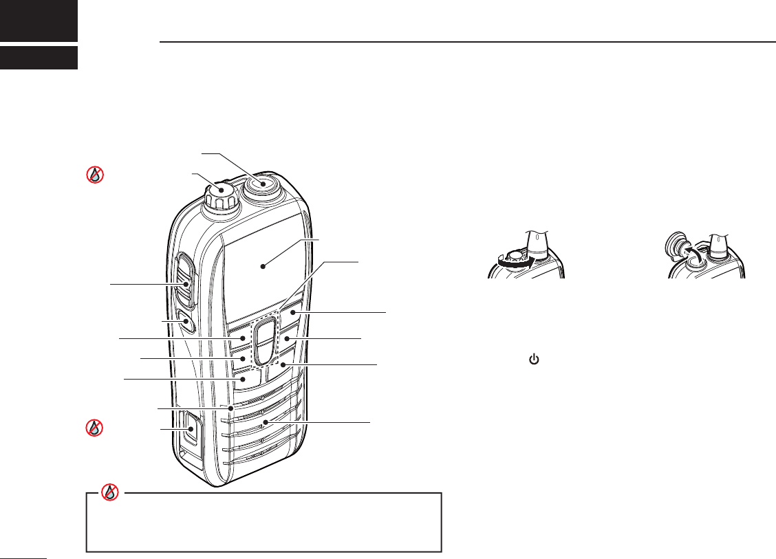
ANTENNA CONNECTOR (p. 2)
Connect the supplied antenna.
SPEAKER/MIC JACK [SP/MIC] (p. 23)
Connect the optional speaker microphone (HM-213) here.
PTT SWITCH [PTT]
Hold down to transmit: release to receive. (p. 11)
POWER KEY [ ]
Hold down to turn power ON or OFF.
CHANNEL 16 KEY [16 9]
±0USHTOSELECT#HANNELP
±
(OLDDOWNFORSECONDTOSELECTTHE#ALLCHANNELP
Function display
Speaker
SCAN
VOL/SQL
[16/9]
PTT
PWR SWICH
[UP/DWN]
[SP/MIC] JACK
Antenna connector
[CH/WX]*
[FAV]
[Hi/Lo]
Microphone
DC JACK
4Close up firmly when no cable is conencted.
4Make sure dust or other material does not adhere to the seal.
Otherwise, waterproof protection may not be guaranteed.
1) Rotate the cap counter clockwise. 2) Pull the cap up to detach it.
N Nomenclature and main functions

VOLUME/SQUELCH/MONITOR KEY [VOL/SQL MONI]
± Push when you adjust the volume level. While the
"VOL" icon blinking, push [UP]/[DWN] to adjust the vol-
ume level.
The Volume Mute function:
± While holding down this key, push [Z] to temporary
maximize the volume level. Do the same operation
again to turn OFF the function.
The Volume Loud function:
± While holding down this key, push [Y] to temporary
mute the audio output. Do the same operation again to
turn OFF the function.
SCAN/DUAL KEY [SCAN DUAL]
± Push to start or stop a normal or priority scan. (p. 15)
±
Hold down for 1 second to enter the Dual/Tri-watch
mode. (p. 16)
± Hold down this key and
[Hi/Lo]
for 1 second, to activate
the Aq
uaQuake function. (p. 13)
CHARGING CONNECTOR
Connect the supplied charger.
UP/DOWN KEYS [Y] or [Z]
±0USHTOSELECTANOPERATINGCHANNELPP
FAVORITE/TAG KEY [FAV TAG]
± Push to sequentially select the favorite (TAG) channels
SKIPPINGUNTAGGEDCHANNELSP
± Hold down for 1 second to set or clear the selected
channel as the TAG channel. (p. 15)
CHANNEL/WEATHER CHANNEL KEY [CH/WX U/I/C]
± Push to switch between a regular channel and a
WEATHERCHANNELP
± Hold down for 1 second to select the channel group
FROM53!)NTERNATIONALAND#ANADAP
TRANSMIT POWER/LOCK KEY [Hi/Lo ]
±
Push to
select the output power from
high
and
low.
(p. 11)
± Hold down for 1 second to lock the key.
5
3
PANEL DESCRIPTION
1
2
3
4
5
6
7
8
9
10
11
12
13
14
15
16
6
3PANEL DESCRIPTION
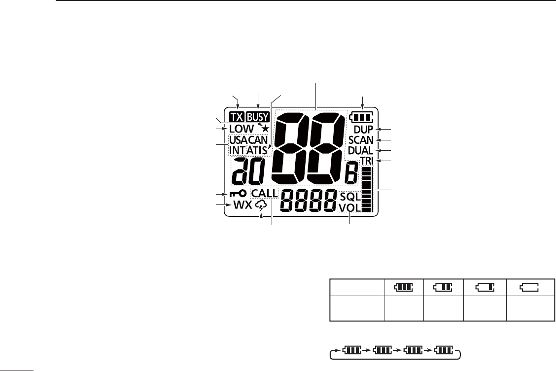
N Function display
TRANSMIT ICON (p. 11)
Appears while transmitting.
BUSY ICON
± Appears while receiving a signal or when the squelch
opens. (p. 11)
±"LINKSWHILETHE-ONITORFUNCTIONIS/.P
TAG CHANNEL ICON (p. 15)
Appears when a TAG channel is selected.
CALL CHANNEL INDICATORP
Appears when the Call channel is selected.
BATTERY ICONS
± Displays the remaining battery capacity.
Indication
Full Middle Charging
required Exhausted
Battery status
± Scrolls while charging.
BUSY ICON ATIS
CHANNEL NUMBER READOUT
BATTERY ICONS
TRANSMIT ICON
LOW POWER INDICATOR
TAG CHANNEL ICON
CHANNEL GROUP INDICATOR
KEY LOCK ICON
WX Alert
received
WX channel is selected
CALL CHANNEL
INDICATION
Blinks while adjusting.
“SQL”= Squelch level “VOL”= Volume level
VOLUME/SQUELCH LEVEL ICON
DUPLEX INDICATOR
TRI-WATCH INDICATOR
DUALWATCH INDICATOR
SCAN INDICATOR

SCAN INDICATOR (p. 15)
"LINKSDURINGASCAN
LOCK ICON (p. 13)
Appears when the Lock function is turned ON.
DUALWATCH/TRI-WATCH INDICATORS (p. 16)
“DW” appears during Dualwatch.
“TW” appears during Tri-watch.
DUPLEX INDICATOR
Appears when a duplex channel is selected.
SUB CHANNEL READOUT
± Displays Channel 16 during a priority scan, Dualwatch
or Tri-watch. (p. 16)
± Displays the Set mode item while in the Set mode. (p. 17)
SQUELCH/ VOLUME LEVEL ICON
± Displays the squelch/volume level.
± “ SQL” blinks while adjusting the squelch level. (p. 10)
± “ VOL” blinks while adjusting the volume level. (p. 10)
± The bars repeatedly appear in ascending order when
the Volume Loud function is turned ON. (p. 12)
± The bars blink while the Volume Mute function is turned
ON. (p. 12)
CHANNEL NUMBER READOUT
Displays the selected operating channel number.
CHANNEL GROUP ICON P
Displays the selected channel group.
WEATHER CHANNEL/WEATHER ALERT ICONS P
± “WX” appears when the weather channel group is se-
lected.
± “” appears while the Weather Alert function is turned
ON, and blinks when the alert tone is received.
LOW POWER ICON (p. 11)
± “ LOW” appears when the low TX power is selected.
± “LOW” blinks when switching to the low power mode is
forced because of a high temperature error or low volt-
age.
7
3
PANEL DESCRIPTION
1
2
3
4
5
6
7
8
9
10
11
12
13
14
15
16

BASIC OPERATION
4
N Selecting channel
Choose the appropriate channel groups for your operating
area, and then select the channel.
D Selecting channel group
4 HETRANSCEIVERISPREPROGRAMMEDWITH53!)NTERNA-
tional and 65 Canadian channels.
± Hold down [U/I/C] (CH/WX) for 1 second to change the
channel group. Repeat to advance to the next group.
D Selecting regular channel
±Push [Y] or [Z] to select a channel.
shDUP” appears for duplex channels.
sh!vAPPEARSWHENASIMPLEXCHANNELISSELECTED

D Channel 16
Channel 16 is the distress and safety channel. It is used for
establishing initial contact with a station, and for emergency
communications. While in the standby mode, you must moni-
tor Channel 16.
q Push [16] momentarily to select Channel 16.
w
Push [CH/WX] to recall the channel, displayed before se-
lecting Channel 16.
D Channel 9 (Call channel)
#HANNELISALEISUREUSE#ALLCHANNEL%ACHCHANNELGROUP
has a Call channel.
q Hold down [9] (16) for 1 second to select the Call channel
of the selected channel group.
shCALL” and the Call channel number appear.
w
Push [CH/WX] to recall the channel displayed before select-
ing Channel 16.
D Weather channels
The transceiver has 10 weather channels. These are used
for monitoring broadcasts from NOAA (National Oceanic and
Atmospheric Administration).
The transceiver can automatically detect a weather alert
tone on the selected weather channel while receiving an-
OTHERCHANNELORDURINGASCANP
q Push [CH/WX] once or twice to select the Weather chan-
nel group.
shWX” appears when a weather channel is selected.
w Push [Y] or [Z] to select a weather channel.
4
"!3)#/0%2!4 )/.
1
2
3
4
5
6
7
8
9
10
11
12
13
14
15
16
10
4"!3)#/0%2!4 )/.
N Receiving and transmitting
CAUTION: Transmitting without an antenna can damage
the transceiver.
q Push [Y] or [Z] to select the channel.
s7 HENASIGNALISRECEIVEDh ” appears.
w
Hold down [PTT], and then speak into the microphone.
sh ” appears while transmitting.
e Release [PTT] to receive.
IMPORTANT: To maximize the readability of your trans-
mitted signal, pause for a second after pushing [PTT],
hold the microphone 5 to 10 cm (2 to 4 inches) from your
mouth and speak into the microphone at a normal voice
level.
For U.S.A version: To prevent prolonged transmission, a
time-out timer cuts OFF after 5 minutes of continuous
transmission.
N Adjusting the volume level
You can adjust the volume level while the “VOL” icon is blinking.
q
Push [VOL/SQL] once.
s4 HEhVOL” icon starts blinking.
s)FNOKEYOPERATIONISPERFORMEDFORSECONDSTHETRANSCEIVER
returns to the normal mode.
w
Push [Y] or [Z]
to adjust the volume level.
s4 HELEVELISDISPLAYEDONTHESCREEN
e Push
[VOL/SQL]
twice.
s2ETURNSTOTHENORMALOPERATINGMODE
4) Release to receive.
1) Select a channel.
2) Push to transmit.
3) Speak into the microphone.

N Adjusting the squelch level
Squelch is a function that allows the audio to be heard only
while receiving a signal that is stronger than a set level. You
can adjust the squelch threshold level.
A higher level blocks weak signals, so you receive only
stronger signals. A lower level allows you to hear weak sig-
nals including noise.
Adjust the squelch level when you want to:
sBLOCKWEAKSIGNALSINCLUDINGNOISE3ETTHELEVELHIGHER
sHEARWEAKSIGNALSEVENINTHENOISE3ETTHELEVELLOWER
You can adjust the squelch level while the “SQL” icon is blinking.
q
Push [VOL/SQL] twice.
s4 HEhSQL” icon starts blinking.
s)FNOKEYOPERATIONISPERFORMEDFORSECONDSTHETRANSCEIVER
returns to the normal mode.
w
Push [Y] or [Z]
to adjust the squelch level.
s4 HELEVELISDISPLAYEDONTHESCREEN
e Push
[VOL/SQL]
once.
s2ETURNSTOTHENORMALOPERATINGMODE
N Monitor function
The Monitor function momentary cancels the squelch func-
tion. You can check for weak signals including noise.
± Hold down
[MONI] (VOL/SQL)
.
sh ” blinks.
s)FTHEREISAWEAKSIGNALYOUCANHEARTHESIGNALANDNOISE
s
Release [MONI] (VOL/SQL) to return the normal squelch mode.
NOTE:
This function has options. See page ?? for more.
N Toggling the transmit power
If you receive no response to your call, your transmit signal might
not be reached to your callee. Choose high power (5 W: default) for
longer distance communications.
On the other hand, transmitting at low power is enough to commu-
nicate, according to the distance. Choose low power (1 W) for short
range and battery conservation.
±
Push [Hi/Lo] to toggle the transmit power between low and high.
shLOW” is displayed when low power is selected. When high power
is selected, no icon is displayed.
NOTE:
s3OMECHANNELSARERESTRICTEDTOLOWPOWER
sYou cannot transmit on Channel 70. 11
4
"!3)#/0%2!4 )/.
1
2
3
4
5
6
7
8
9
10
11
12
13
14
15
16

12
4"!3)#/0%2!4 )/.
N Volume Loud function
You can temporary maximize the volume level with a simple
operation.
q While holding down [VOL/SQL], push [Y].
s4 HEVOLUMELEVELISSETTOTHEMAXIMUMLEVEL
s4 HEBARSOFTHEVOLUMELEVELICONREPEATEDLYAPPEARINASCEND-
ing order.
w Push [VOL/SQL] and [Y] again to turn OFF the function.
N Volume Mute function
You can temporary mute the audio output with a simple op-
eration.
q While holding down [VOL/SQL], push [Z].
s4 HEVOLUMELEVELISSETTOTHEMINIMUMLEVEL/&&
s4 HEBARSOFTHEVOLUMELEVELICONBLINK
w Push [VOL/SQL] and [Z] again to turn OFF the function.
N Lock function
This function electronically locks the keys to prevent acci-
dental changing of the channel and function access.
± Hold down
[ ]
(Hi/Lo) for 1 second to turn the function
ON and OFF.
NOTE:
[PTT], [VOL/SQL], [MONI] (VOL/SQL), [ ] (Hi/Lo) and [Y]
or [Z]* are not locked.
* Only while the adjusting the volume or squelch, and volume loud
and Volume Mute functions.
N
AquaQuake Water Draining function
Water in the speaker grill may muffle the sound coming from
the speaker. The AquaQuake Water Draining function removes
water from the speaker grill, by generating vibrating sound.
± Hold down both [SCAN] and [Hi/Lo].
s!LOWVIBRATIONTONESOUNDSFORSECONDSTODRAINWATERRE-
gardless of the volume level setting.
s4 HETRANSCEIVERDOESNOTACCEPTANYKEYOPERATIONSWHILETHIS
function is activated.

13
4
"!3)#/0%2!4 )/.
1
2
3
4
5
6
7
8
9
10
11
12
13
14
15
16
N Setting TAG channels
You can quickly recall often-used channels by tagging them
as TAG channels.
TAG channels can be independently assigned to each chan-
nel group (USA, International and Canada).
q Hold down [U/I/C] (CH/WX) for 1 second to change the
channel group, if needed. Repeat to go to the next group.
w
Select the desired channel you want to set as a TAG channel.
e Hold down [*] (FAV) for 1 second.
s4 HEDISPLAYEDCHANNELISSETASA4 !' CHANNEL
sh ” appears on the display.
To select a TAG channel:
± Push [FAV] (*) several times to select the desired TAG
channel.
s.ON4 !' channels are skipped.
To clear a TAG channel:
q Select the desired channel you wan to clear the tagging.
w Hold down [*] (FAV) for 1 second.
sh ” disappears.
To clear all TAG channels:
± While holding down [*] (FAV), turn ON the power.
s!LL4 !' CHANNELSINTHESELECTEDCHANNELGROUPARECLEARED
N
Setting the Call channel
You can recall the most often-used channel with a single op-
eration, by setting the channel as a Call channel.
A Call channel can be set in each channel group.
q Hold down [U/I/C] (CH/WX) for 1 second to change the
channel group. Repeat to go to the next group.
w Hold down [9] (16) for 1 second to recall the current Call
channel in the selected group.
shCALL” and the Call channel number appear.
e Hold down [9] (16) again for 3 seconds (until a long beep
changes to 2 short beeps) to enter the Call channel set-
ting mode.
s4 HECHANNELNUMBERSTARTSBLINKING
r Push [Y] or [Z] to select the new Call channel.
t Push [9] (16) to set.
s4 HECHANNELNUMBERSTOPSBLINKING
14
SCAN OPERATION
5
N Scan types
You can efficiently locate signals over the channels by scan-
ning. You can find the ongoing call by scanning the TAG
channel.
Before starting to scan:
s/NLY4 !' CHANNELSARESCANNEDSOYOUMUSTSETTHECHAN-
nels to be scanned, before scanning.
s#HOOSETHEDESIREDSCANTYPEFROM0RIORITYAND.ORMAL
in the Set mode.
PRIORITY SCAN
A priority scan sequentially searches through all TAG
channels while monitoring Channel 16.
When a signal is received on Channel 16, the scan
pauses until the signal on Channel 16 disappears.
When a signal is received on a channel other than Chan-
nel 16, the scan switches to Dualwatch, until the signal
disappears.
NORMAL SCAN
A normal scan sequentially searches through all TAG
channels. However, Channel 16 is not checked unless
Channel 16 is set as a TAG channel.
WX*
CH 01
CH 16
CH 02
CH 05 CH 04
CH 03
Previously selected weather channel.
(when the Weather Alert function is activated)
*
CH 01 CH 02
WX*
CH 05 CH 04
CH 03
Previously selected weather channel.
(when the Weather Alert function is activated)
*

N Start to scan
q Hold down [U/I/C] (CH/WX) for 1 second one or more
times to select a desired channel group.
s7 HENTHE7 EATHER!LERTFUNCTIONISINUSESELECTADESIRED
weather channel using [CH/WX] and [Y] or [Z].
w Push [SCAN] to start a scan.
shSCAN” blinks while scanning.
shvAPPEARSONTHESUBCHANNELREADOUTDURINGAPRIORITYSCAN
s7 HENASIGNALISRECEIVEDTHESCANPAUSESUNTILTHESIGNAL
disappears, or resumes after pausing 5 seconds, depending on
the Set mode setting.
e To stop the scan, push [SCAN] again.
shSCAN” disappears.
s0USHING[PTT], [16], [CH/WX] or [FAV] also stops the scan.
15
5
SCAN OPERATION
1
2
3
4
5
6
7
8
9
10
11
12
13
14
15
16
16
DUALWATCH AND TRI-WATCH
6
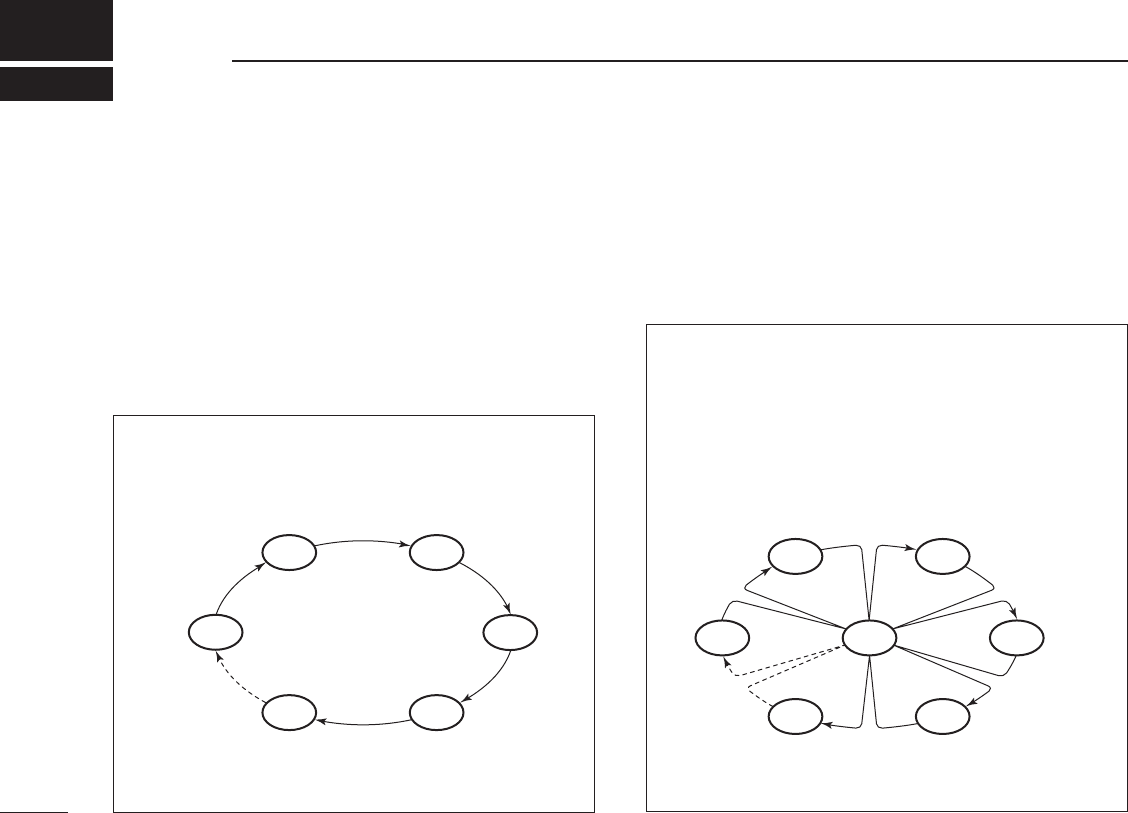
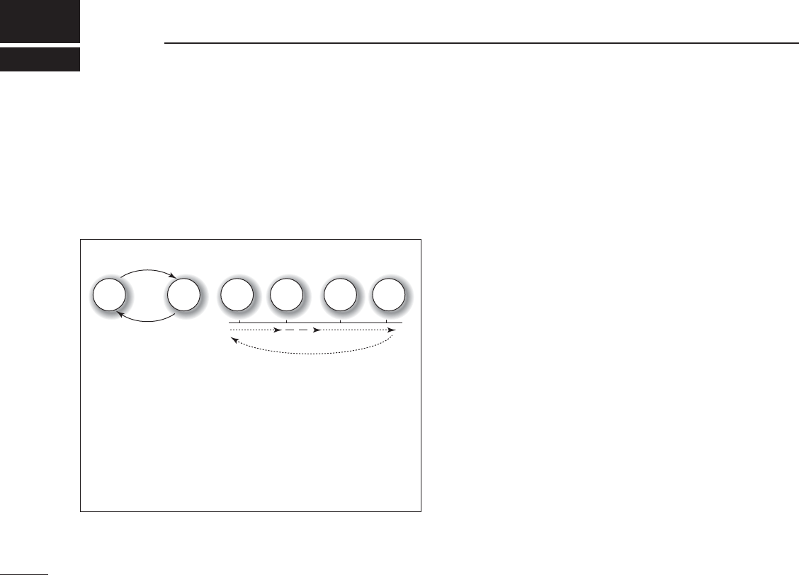
N Description
Dualwatch/Tri-watch are convenient for monitoring Channel
16 when you are operating on another channel.
Dualwatch monitors Channel 16 while you are receiving
on another channel.
Tri-watch monitors Channel 16 and Call channel while re-
ceiving on another channel.
N Operation
q3ELECT$ UALWATCHOR4 RIWATCHINTHE3ETMODEP
w Select the desired channel.
e
Hold down [DUAL] (SCAN) for 1 second to start Dual-
watch
or Tri-watch, depending on the Set mode setting.
shDUAL” blinks during Dualwatch. “TRI” blinks during Tri-watch.
s!BEEPTONESOUNDSWHENASIGNALISRECEIVEDON#HANNEL
s4 RIWATCHSWITCHESTO$ UALWATCHWHENRECEIVINGASIGNALONTHE
Call channel.
r
To cancel Dualwatch/Tri-watch, push [DUAL] (SCAN)
again.
s)FASIGNALISRECEIVEDON#HANNEL$ UALWATCH4 RI
watch pauses on Channel 16 until the signal disappears.
s)FASIGNALISRECEIVEDONTHE#ALLCHANNELDURING4 RI
watch, Tri-watch becomes Dualwatch until the signal dis-
appears.
Dualwatch
DUALWATCH/TRI-WATCH SIMULATION
Tri-watch
Call
channel
Ch 88
Ch 16 Ch 88 Ch 16 Ch 88 Ch 9

N Set mode programming
The Set mode is used to select an option for the transceiv-
er's functions.
D Set mode operation
q Turn OFF the power.
w While holding down [VOL/SQL], turn ON the power to
enter the Set mode.
s4 HESTARTINGITEMhB%%0vAPPEARS
e While holding down [VOL/SQL], push [Y] or [Z] to select
an item.
r Push [Y] or [Z] to select an option of the item.
t Push [16] to exit the Set mode, .
17
7
SET MODE
1
2
3
4
5
6
7
8
9
10
11
12
13
14
15
16

7SET MODE
N Set mode items
D Beep Tone function “bEEP”
Turn the key touch beep sound ON or OFF.
s/&&&ORSILENTOPERATION
s/. !BEEPSOUNDSWHENAKEYISPUSHED
D Weather Alert function “ALrt”
A NOAA broadcast station transmits a weather alert tone be-
fore any important weather announcements. When the func-
tion is turned ON and the transceiver detects a weather alert
tone, the “WX ” icon blinks and a beep sounds. The blinking
stops when an operation is performed.
The currently selected weather channel is checked while the
Power Save function is activated, or during a scan.
sh vAPPEARSWHENTHE7 EATHER!LERTFUNCTIONISTURNED/.P
” appears when the function is set to ON.
D Priority Scan function “Prio”
The transceiver has 2 scan types— Normal (OFF) and Pri-
ority (ON) scan. A normal scan searches all TAG channels
in the selected channel group. A priority scan sequentially
searches all TAG channels while monitoring Channel 16.
D Scan resume timer “S_ti”
Select the scan timer option.
s/&&7 HENASIGNALISRECEIVEDTHESCANPAUSESONTHECHANNEL
until the signal disappears.
s/. 7 HENASIGNALISRECEIVEDTHESCANPAUSESONTHECHANNEL
for 5 seconds, and then resumes.
() y

D Auto Scan function “Auto”
The Auto Scan function automatically starts a normal or
priority scan when no signal is received, and no operation is
performed for 30 seconds.
D Dual/Tri-watch function “dt”
Set the watch type to Dualwatch or Tri-watch. (p. 16)
D Monitor key action “SqLS”
The monitor key
momentary cancels the squelch function
.
Select a key action option.
s0U053( 4 HE-ONITORFUNCTIONISACTIVATEDWHILEHOLDINGDOWN
[MONI] (VOL/SQL). The squelch function is can-
celed while holding down the key.
s(O(/,$ 4 HE-ONITORFUNCTIONISACTIVATEDBYHOLDINGDOWN
[MONI] (VOL/SQL) for 1 second. The squelch func-
tion is canceled until any key is pushed again.
7
SET MODE
1
2
3
4
5
6
7
8
9
10
11
12
13
14
15
16

20
7SET MODE
D Automatic backlighting “A_bL”
This function is convenient for the operation in the night. The
backlight can be selected from ON and OFF.
s4 HEBACKLIGHTISAUTOMATICALLYACTIVATEDWHENANYKEYEXCEPT
[PTT] is pushed.
s4 HEBACKLIGHTISAUTOMATICALLYTURNED/&&AFTERSECONDSOFINAC-
tivity.
D LCD contrast setting “Lcdc”
Set the LCD contrast level to High contrast or Low contrast.
The LCD contrast level has little effect during indoor use.
D Power Save function “P_SA”
The Power Save function reduces current drain by periodi-
cally turning OFF the receiver circuit.
s/&& 4 HEFUNCTIONISTURNED/&&
s/. When no signal is received, and no operation is performed
for 5 seconds, the Power Save function is activated.
D Float Alert function “FLAr”
Alert periodically sounds while the radio is floating in the
water so that you can noticed that you dropped the radio.
s/&& 4 HEFUNCTIONIS/&&
s/. Alert periodically sounds while the radio is floating in the
water.
D Automatic Water Draining function “AquA”
This function automatically activates the AquaQuake Water Drain-
ing function when the radio has been retrieved from the water.
s/&& 4 HEFUNCTIONIS/&&
s 4 HE!QUA1UAKE7 ATER$ RAININGFUNCTIONISAUTOMATICALLY
activated and A low vibration tone sounds for the specified
time period (2, 5 or 10 seconds).

21
CHARGING
1
2
3
4
5
6
7
8
9
10
11
12
13
14
15
16
N Battery caution
D Charging caution
CAUTION: DO NOT charge the battery outside of the specified
temperature range: ±0˚C to +45˚C (+32˚F to +113˚F). Icom recom-
MENDSCHARGINGTHEBATTERYAT#&4 HEBATTERYMAYHEAT
up or rupture if charged out of the specified temperature range, and
battery performance or battery life may be reduced.
Charge the battery at least once every six months, even if it has
been not used for a long period of time. The battery will have slowly
self-discharged, even though it has not been used. If the battery
pack is left for a long period without being charged, its life cycle will
be shorter, or worse, it will never accept a charge again.
When the battery life cycle is shorter, it is time to replace it with a
new one. Contact your Icom's local service shop about replacing the
inside battery pack.
Misuse of Lithium-ion batteries may result in the follow-
ing hazards: smoke, fire, or the battery may rupture.
Misuse can also cause damage to the battery or deg-
radation of battery performance.
22
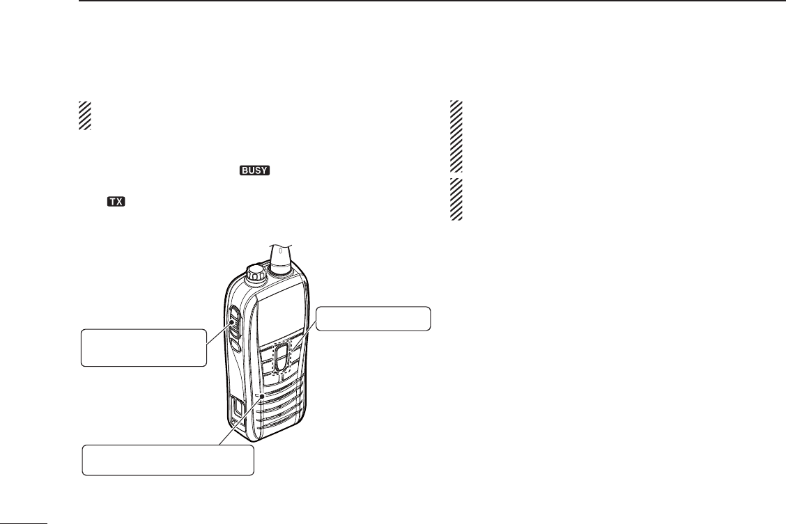
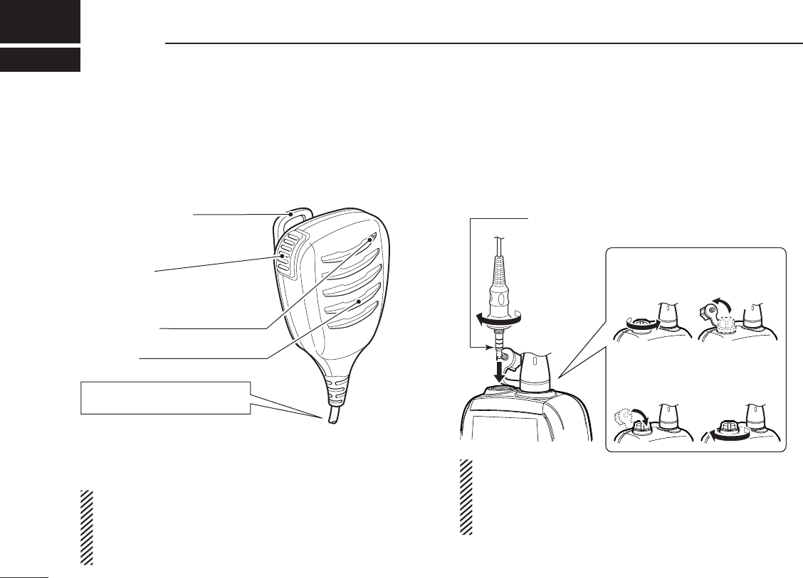
N HM-213 descriptions
A speaker microphone is light weight and fits in your palm
and allows you to talk and listen more easier. The HM-213
speaker microphone is prepared for the IC-M25/M25EURO.
PTT switch
Transmits during push.
Receives during release.
Microphone
Speaker
Alligator type clip
To attach the speaker-mic.
to your shirt or collar, and so on.
Turn the transceiver power OFF
when connecting the HM-213.
NEVER immerse the connector in water. If the connector
GETSWETBESURETODRYIT"%&/2%ATTACHINGITTOTHETRANS-
ceiver.
NOTE: The microphone is located at the top of the
speaker-microphone, as shown above. To maximize the
readability of your transmitted signal (voice), hold the mi-
crophone approx. 5 to 10 cm (2 to 4 inches) from your
mouth, and speak in a normal voice level.
N Attachment
Turn OFF the power. Then, insert the speaker-mic connector
into the [SP MIC] connector and carefully screw it tight, as
SHOWNBELOW"ECAREFULNOTTOCROSSTHREADTHECONNECTION
CAUTION: Attach the speaker-microphone’s
connector securely to prevent accidental
loss, or water intrusion in the connector.
Detaching:
Rotate the [SP MIC] cap counter-
clockwise (1), then detach it (2).
Attaching:
Attach the
[SP MIC]
cap (
1
), then
rotate it clockwise completely (
2
).
12
2
1
IMPORTANT: KEEP the transceiver’s [SP MIC] cap attached
when the speaker-microphone is not in use. If the cover is
not attached, water will get into the transceiver. Moreover,
the terminals (pins) will become rusty, or the transceiver will
function abnormally if the connector gets wet.
OPTIONAL SPEAKER-MICROPHONE
23
10
TROUBLESHOOTING
1
2
3
4
5
6
7
8
9
10
11
12
13
14
15
16
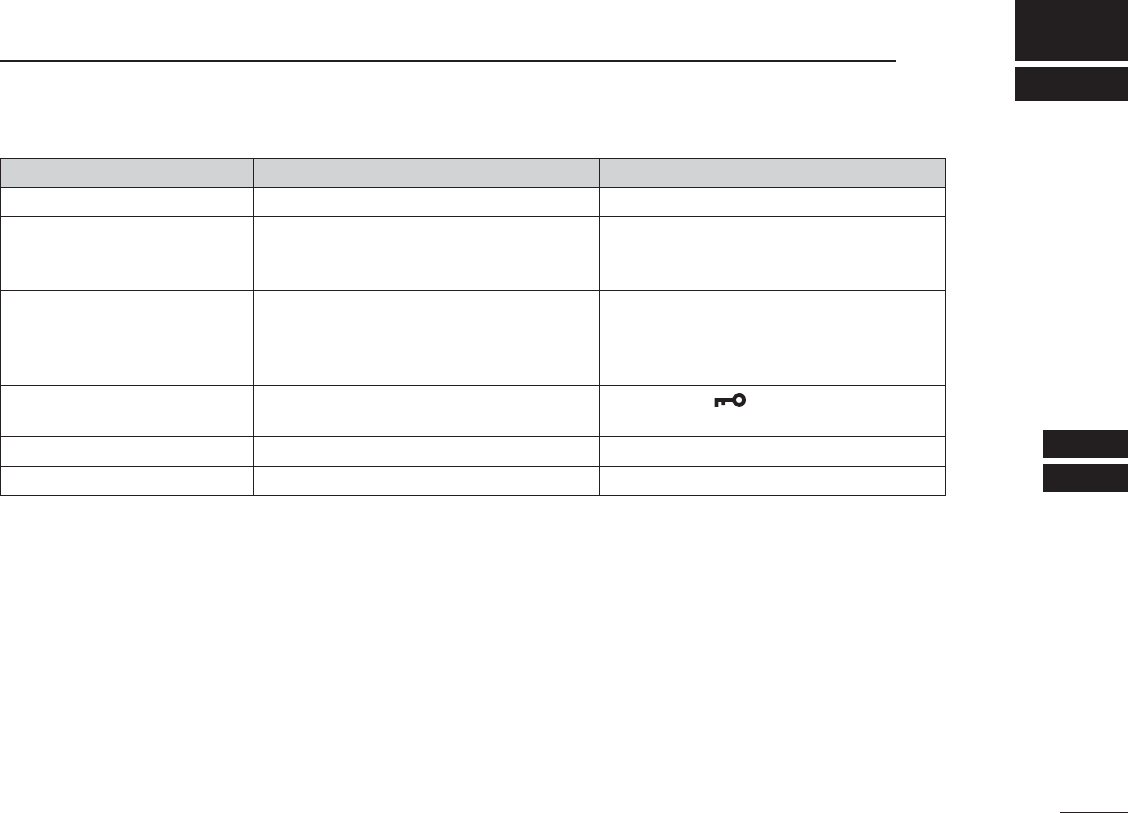
PROBLEM POSSIBLE CAUSE SOLUTION
The transceiver does not turn ON.
s4 HEBATTERYISEXHAUSTED s#HARGETHEBATTERY
No sound from speaker. s4 HESQUELCHLEVELISTOOHIGH
s6 OLUMELEVELISTOOLOW
s3PEAKERHASBEENEXPOSEDTOWATER
s3ETTHE
squelch
level to the
threshold
level.
s!DJUSTTHEAUDIOLEVELTOASUITABLELEVEL
s2EMOVEWATERFROMTHESPEAKERGRILL
Transmitting is impossible,
or high power can not be se-
lected.
s3OMECHANNELSARELIMITEDTOLOWPOWER
or only receive.
s4 HEOUTPUTPOWERISSETTOLOW
s4 HEBATTERYISEXHAUSTED
s#HANGETHECHANNEL
s0USH[Hi/Lo] to select high power.
s2ECHARGETHEBATTERYPACK
The displayed channel cannot
be changed.
s4 HE,OCKFUNCTIONISACTIVATED s(OLDDOWN[] (Hi/Lo) for 1 second to
turn OFF the function.
Scan does not start sh4 !' vCHANNELSARENOTPROGRAMMED s
Set desired channels as “TAG” channels.
No beep sounds. s"EEP4 ONEFUNCTIONISTURNED/&& s4 URN/.THE"EEP4 ONEINTHESETMODE

24
VHF MARINE CHANNEL LIST
11
NOTE: Simplex channels, 3, 21, 23, 61, 64, 81, 82 and 83 CANNOT be lawfully used by the general public in U.S.A. waters.
*
1
Low power only.
*
2
UK Marina Channels: M1=37A (157.850 MHz), M2=P4 (161.425 MHz) for U.K. version only.
hannels
(for U.K. version only)
Frequency (MHz) Frequency (MHz) Frequency (MHz) Frequency (MHz) Frequency (MHz) Frequency (MHz)
Transmit Receive Transmit Receive Transmit Receive Transmit Receive Transmit Receive Transmit Receive
156.050 156.050 156.600 156.600 157.100 157.100 156.225 156.225 156.775 156.775
156.825 156.825
156.875 156.875 157.325 161.925
- - - - - - 156.650 156.650 157.150 157.150 156.275 156.275
156.925 156.925 157.325 157.325
156.150 156.150 156.700 156.700 157.200 161.800 156.325 156.325
156.975 156.975 157.375 161.975
- - - - - - 156.750 156.750 157.250 161.850 156.375 156.375
157.025 157.025 157.375 157.375
156.250 156.250 156.800 156.800 157.300 161.900 156.425 156.425
157.075 157.075 157.425 162.025
156.300 156.300 156.850 156.850 157.350 161.950 156.475 156.475
157.125 157.125 157.425 157.425
161.425 161.425
156.350 156.350 156.900 156.900 157.400 162.000 RX Only 156.525
157.175 157.175
156.400 156.400 156.950 156.950 157.850 157.850 156.575 156.575
157.225 161.825
156.450 156.450 157.000 161.600 156.075 156.075 156.625 156.625
157.225 157.225
156.500 156.500 157.000 157.000 - - - - - - 156.675 156.675
156.550 156.550 157.050 157.050 156.175 156.175 156.725 156.725
157.275 161.875
157.275 157.275
12
13*
1
20A
21A
20
19A
18A
17*
1
16
15*
1
14
CH
22A
23A
- -
63A
61A
37A*
2
28
27
26
25
24
CH
64A
65A
73
74
72
71
70
69
68
67*
1
66A
CH
75*
1
76*
1
84
84A
83A
82A
81A
80A
79A
78A
77*
1
CH
85
85A
P4*
2
88A
88
87A
87
86A
86
CH
01A
- -
10
11
09
08
07A
06
05A
- -
03A
CH

25
11
VHF MARINE CHANNEL LIST
1
2
3
4
5
6
7
8
9
10
11
12
13
14
15
16
CH Frequency (MHz) CH Frequency (MHz) CH Frequency (MHz) CH Frequency (MHz) CH Frequency (MHz) CH Frequency (MHz)
Transmit Receive Transmit Receive Transmit Receive Transmit Receive Transmit Receive Transmit Receive
01 156.050 160.650 11 156.550 156.550 21 157.050 161.650 61 156.075 160.675 71 156.575 156.575 81 157.075 161.675
02 156.100 160.700 12 156.600 156.600 22 157.100 161.700 62 156.125 160.725 72 156.625 156.625 82 157.125 161.725
03 156.150 160.750 13 156.650 156.650 23 157.150 161.750 63 156.175 160.775 73 156.675 156.675 83 157.175 161.775
04 156.200 160.800 14 156.700 156.700 24 157.200 161.800 64 156.225 160.825 74 156.725 156.725 84 157.225 161.825
05 156.250 160.850 15*
1
156.750 156.750 25 157.250 161.850 65 156.275 160.875 75*
3
156.775 156.775 85 157.275 161.875
06 156.300 156.300 16 156.800 156.800 26 157.300 161.900 66 156.325 160.925 76*
3
156.825 156.825 86 157.325 161.925
07 156.350 160.950 17*
1
156.850 156.850 27 157.350 161.950 67 156.375 156.375 77 156.875 156.875 87 157.375 157.375
P4*
2
161.425 161.425
88 157.425 157.425
08 156.400 156.400 18 156.900 161.500 28 157.400 162.000 68
69
156.425 156.425 78 156.925 161.525
09 156.450 156.450 19 156.950 161.550 37A*
2
157.850 157.850 156.475 156.475 79 156.975 161.575
10 156.500 156.500 20 157.000 161.600 60 156.025 160.625 70 RX Only 156.525 80 157.025 161.625
*
1
*
3
Channels 15 and 17 may also be used for on-board communications provided the
effective radiated power does not exceed 1 W, and subject to the national
regulations of the administration concerned when these channels are used in its
territorial waters.
The output power of channels 75 and 76 are limited to low power (1 W) only.
The use of these channels should be restricted to navigation-related
communications only and all precautions should be taken to avoid harmful
interference to channel 16, e.g. by means geographical separation.
UK Marina Channels: M1=37A (157.850 MHz), M2=P4 (161.425 MHz) for U.K.
version only.
*
2

26
SPECIFICATIONS AND OPTIONS
11
N Specifications
D GENERAL
s&REQUENCYCOVERAGE 4RANSMIT n-(Z
Receive 156.050–163.275 MHz
s-ODE &-+ ' %
s0OWERSUPPLYVOLTAGE 6 $ #NOMINALNEGATIVEGROUND
s#URRENTDRAINAPPROXIMATELY 4 8 7 7 !!
Maximum audio with Int. SP
0.30 A typical
Maximum audio with Ext. SP
0.20 A typical
s&REQUENCYSTABILITY ÒPPM
s/PERATINGTEMPERATURERANGE n#TO#n&TO&
s$ IMENSIONS 7 ¾(¾$ MM
PROJECTIONSNOTINCLUDED 7 ¾(¾$ INCH
s7 EIGHT !PPROXIMATELYGOZ
(including battery pack, antenna and belt clip)
D TRANSMITTER
s/UTPUTPOWER 7APPROXIMATELY(IGHAND7 ,OW
s-ODULATIONSYSTEM 6 ARIABLEREACTANCEFREQUENCYMODULATION
s-AXIMUMFREQUENCYDEVIATIONÒK(Z
s!DJACENTCHANNELPOWER D"
s3PURIOUSEMISSIONS nD"CTYPICAL
s2ESIDUALMODULATION D"
s!UDIOFREQUENCYRESPONSE D"TOnD"OFD"OCTFROMn(Z
D RECEIVER
s3ENSITIVITYD"3).!$ §6 TYPICAL
s3QUELCHSENSITIVITY §6 TYPICALATTHRESHOLD
s)NTERMODULATION D"TYPICAL
s3PURIOUSRESPONSE D"TYPICAL
s!DJACENTCHANNELSELECTIVITY D"TYPICAL
s!UDIOOUTPUTIMPEDANCE
12 Ω (Internal speaker), 4 Ω (External speaker)
s!UDIOOUTPUTPOWER 7 TYPICAL)NT30
(at 10% distortion) 0.30 W typical (Ext. SP)
All stated specifications are subject to change without notice or obligation.
N Options
D CHARGERS
s"# AC ADAPTER
For charging.
Charging time: Approximately 3 hours
D OTHER OPTIONS
s&! 3# 6ANTENNA
s-" BELT CLIP
s( -SPEAKER-MICROPHONE
Full sized waterproof speaker-microphone including alligator type
clip to attach to your shirt or collar, etc.
Approved Icom optional equipment is designed for optimal performance when
used with an Icom transceiver. Icom is not responsible for the destruction or
damage to an Icom transceiver in the event the Icom transceiver is used with
equipment that is not manufactured or approved by Icom.
Some options may not be available in some countries. Please ask your dealer
for details.

MEMO

MEMO

MEMO

1-1-32 Kamiminami, Hirano-ku, Osaka 547-0003, Japan
A-7227-1EX
Printed in Japan
© 2015 Icom Inc.
Printed on recycled paper with soy ink.