ICOM orporated 374000 IP501H User Manual
ICOM Incorporated IP501H
Contents
- 1. User Manual Warnings
- 2. User Manual
User Manual
GUIDE
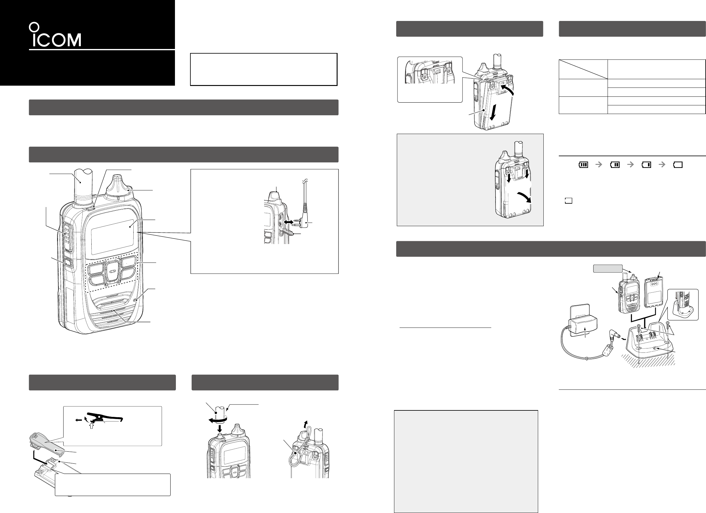
1. SUPPLIED ACCESSORIES
2. PANEL DESCRIPTION
3. ATTACHING THE BELT CLIP 4.
ATTACHING THE ANTENNA/HAND STRAP
• Battery pack (BP-272) ………………………………1 • Belt clip (MB-135)………………………1 • Antenna ………………………………… 1
• Hand strap ……………………………………………1
★1 Ask for your dealer about the assigned function.
★2 While connecting an optional speaker microphone, the audio is not output from
the internal speaker.
Fully charge the battery pack when fist time of use or has not
been used for more than 2 months.
WARNING! NEVER charge the communication
terminal during a lightning storm. It may result in an
electric shock, cause a re or damage the communication
terminal. Always disconnect the power adapter
before a storm.
• Turn OFF the power before charging.
Otherwise, the battery may not be fully charged.
• Insert the communication terminal (battery attached to
the communication terminal) into the charger as shown
to the light.
• Charging indicator lights orange while charging. When
the battery pack is fully charged, lights green.
If the indicator blinks in orange, read the IP501H
instruction manual on the Icom web site.
• The charger automatically restarts charging when the
attached battery pack voltage drops.
• Disconnect the AC cable from the outlet when the
charger is not in use.
7. BATTERY CHARGING (Using the BC-202)
5.
ATTACHING THE BATTERY PACK
About the battery life cycle
BE SURE to replace the battery pack with a new one after ve
years, even if still holds a charge. The material inside the battery will
deteriorate after a period of time, even with little use. The estimated
number of times you can charge the battery is between 300 and 500.
Even when the battery appears to be fully charged, the operating
time of the communication terminal may become short when:
・ Approximately ve years have passed since the battery was
manufactured.
・ The battery has been repeatedly charged.
Follow the order (1 ~ 2) on the illustration below.
NOTE: Instructions and screens on this guide may differ, depending on the
settings.
※ Remove the battery pack before attaching the belt clip.
CAUTION
Even when the communication terminal
power is OFF, a small current still flows
in the communication terminal. Remove
the battery pack or case when not
using it for a long time. Otherwise, the
batteries will become exhausted.
NOTE: Turn OFF the power before
remove the battery pack in
order (1 ~ 2) on the illustration
to the left.
Battery
Spec item BP-272
Operating time 17 hours (Approximately)
TX:RX:Stand-by=5:5:90
Charging time 3.5 hours (Approximately)
Charging with BC-202 or BC-211
※ The supplied battery is BP-272.
• Immediately stop using the battery if it emits an abnormal
odor, heats up, or is discolored or deformed. If any of
these conditions occur, contact your Icom dealer or
distributor.
※ When the battery charge is almost exhausted, the battery status indicator,
“,” starts blinking, and warning beeps sound every 30 seconds.
Charge the battery pack when the beeps begin to sound.
※ When “LOW BATTERY” is displayed, the communication terminal power
will automatically turn OFF soon.
NOTE: Operating time or charging time may be shorter depending
on the environment such as roaming frequency.
6. STANDARD CHARGING TIME AND
BATTERY LIFE
IP ADVANCED RADIO SYSTEM
Supplied
hand strap
Battery pack
q
q
w
Hold this part to turn.
Optional rapid charger BC-202
AC Outlet
Charge indicator
Tapping screw
(Purchase separately)
[Battery pack]
[Terminal+Battery pack]
Turn OFF
BC-123S
(Supplied with BC-202)
Charging :
Orange
Finished : Green
About the remaining voltage indication
Blink
sufficient
capacity
exhausted a
little.
nearing exhaustion
(Charging is necessary)
Exhausted
(Charging required)
When connecting optional
equipment
◎ Be sure to turn power
OFF before connecting
or disconnecting optional
equipment to or from the
jack.
◎ Hold the plug when you
remove the cable.
◎ Insert the plug securely when connecting the cable.
◎ CAUTION: Attach the jack cover when optional equipment is
not used.
Connector
cover
Plug
[PWR/VOL] dial
Supplied antenna
Antenna
[PTT] switch
[Optional]
key★1
[PWR/VOL]
dial
Function
screen
Keypad
(Refere to the
other side.)
Microphone
Speaker★2
[TX/RX] indicator
IP501H
After attaching, check that
the battery pack is securelly
attached. q
w
Slide the belt clip in the direction of the
arrow until the belt clip locks in place, and
makes a ‘click’ sound.
Supplied belt clip
Battery pack
q
w
Lift the tab up (1), and slide the belt
clip in the direction of the arrow (2).
Thank you for choosing the IP501H
ip advanced radio
system communication terminal.
READ ALL INSTRUCTIONS carefully and completely
before using this product.
RDANGER
• Use and charge only specied Icom battery
packs with Icom communication terminals or Icom
chargers. Only Icom battery packs are tested and
approved for use with Icom communication terminals
or charged with Icom chargers. Using thirdparty or
counterfeit battery packs or chargers may cause
smoke, re, or cause the battery to burst.
• Use the battery only with the communication
terminal for which it is specied. Never use a battery
with any other equipment, or for any purpose that is
not specied in this instruction manual.
• Read "PRECAUTION" before attempt to charging
the battery pack.
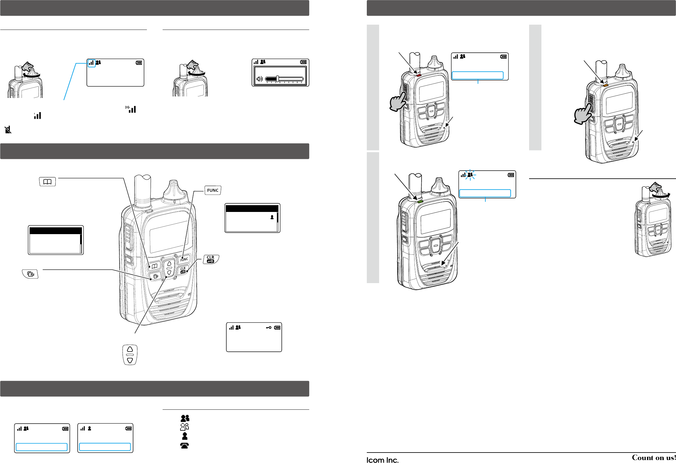
9. ABOUT THE KEY OPERATIONS
10. About the Call types (Calling party)
11. Making a Call
Hold down [PTT], and speak into the microphone.
[TX/RX] indicator lights red while [PTT] is pushed.
1
When receiving a call, [TX/RX] indicator lights green.
2
Turning OFF the power
Turn [PWR/VOL] maximum counter
clockwise.
8. TURNING ON THE POWER/ADJUSTING THE AUDIO LEVEL
Turning ON the power Adjusting the audio output level
Turn [PWR/VOL] to adjust the audio output level.
Set the output to a suitable level.
•A volume level between 0 and 32 is displayed.。
Turn [PWR/VOL] clockwise to set the 12 O'clock position.
A beep sounds.
※ The dial is made physically tight for the dust and water resistance.
The signal strength is represented by 3 bars indication.
In the 3G mode, the resceived signal strength is indicated by the icon.
In the LTE mode, icon is displayed.
※
When the terminal is out of the service area, or cannot receive the signal,
(out-of-service)
icon blinks.
NOTE: If the output level is set to the minimum level, the beep does not
sound.
Standby screen Standbyscreen
Turn
Turn
全体
10/4 12:57
音量
:10
All Call transmitting screen
全体
10/4 12:57
全体
10/4 12:58
Blinks when receive a Call
Turn
[Call List address book] key★
When making a group or
individual call, select calling
party from this list.
Push this button again to switch the radio screen for
“All Call”,“Group Call” or “Individual Call” address
book.
[Function] key★
Selects the message to send,
Presence or Talk group.
個別
00005
集合してください
メッセージ
(Example: A message is selected.)
All Call receiving screen
When Address Book is activated, the radio will display calling party.
Otherwise the radio pre‐programmed calling party will be displayed.
[▲]/[▼] key
Push to scroll the address book or
call history table.
全体
10/4 12:57
営業
8
10/4 12:57
All Call screen Individual Call Screen
Calling Mode Icons*
:
All Group Call
:
Group Call
:
Individual Call
:
Phone Call
While receiving a call, push [PTT] to talk in the full duplex
mode*.
In the Full Duplex mode, [TX/RX] indicator lights orange.
* Depending on the presetting, ask your dealer for detail.
3
※ Instructions and screens on this guide may differ, depending on the settings.
★ Can be used, depending on the presetting.
* Blink when a call or message is received.
Icom, Icom Inc. and the Icom logo are registered trademarks of Icom Incorporated (Japan) in Japan, the United States, the
United Kingdom, Germany, France, Spain, Russia, Australia, New Zealand and/or other countries.
A?????-?EX Printed in Japan
© 2017 Icom Inc.
1-1-32 Kamiminami, Hirano-ku, Osaka 547-0003, Japan
[Call history] key ★
Repeatedly push to select call history from the TX log,
RX log, TX MSG log, RX MSG log, TX TEL log or RX
TEL log.
• Selectable log may differ, depending on the IP1000C
settings.
• Push [Up]/[Dwn] to select a desired log.
• Hold down until “Emergency” is displayed to send an
emergency call, depending on the settings.
個別
個別
00001
00001
Address book: Individual
[CLR/LOCK] key
Push to bring back normal
operating screen from a function
screen such as Call History
screen.
Hold down to turn the key lock
ON or OFF.
※ [PTT] key and [PWR/VOL] dial
can be operated even while in
the Key Lock function is acti-
vated.
全体
10/4 12:57
(Example: Key Lock falling munction is ON.)
Lights red
Lights orange
Lights green
Hold down
Hold down
Microphone
Microphone
Speaker