ICOM orporated 375410 Scanning receiver User Manual
ICOM Incorporated Scanning receiver Users Manual
UserManual.wiki
>
ICOM orporated
>
375410 User Manual
Users Manual
Navigation menu
Upload a User Manual
Namespaces
Wiki Guide
HTML
PDF
Info
Views
User Manual
Discussion / Help
Navigation
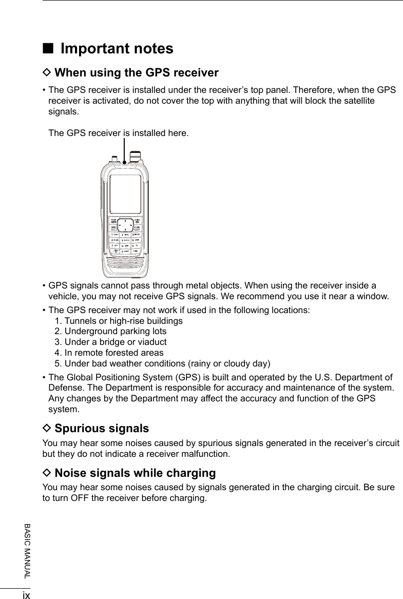
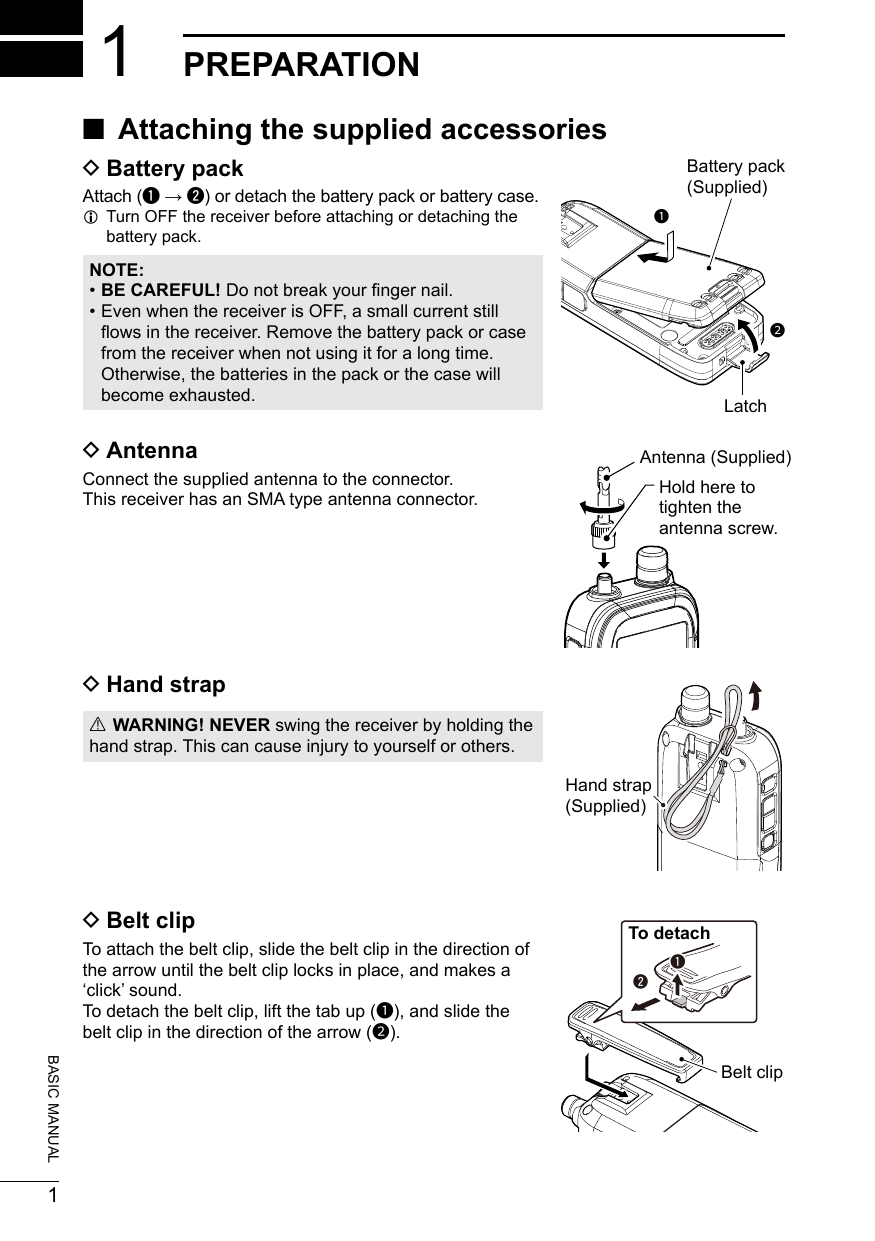
![iv174101518281351116391461217BASIC MANUAL ■Precautions RDANGER! NEVER operate the receiver near unshielded electrical blasting caps or in an explosive atmosphere. This could cause an explosion and death. RWARNING! NEVER use or charge Icom battery packs with non-Icom receivers or non-Icom chargers. Only Icom battery packs are tested and approved for use with Icom receivers or charged with Icom chargers. Using third-party or counterfeit battery packs or chargers may cause smoke, re, or cause the battery to burst. RWARNING! NEVER operate the equipment with a headset or other audio accessories at high volume levels. The continuous high volume operation may cause a ringing in your ears. If you experience the ringing, reduce the volume level or discontinue use. RWARNING! NEVER operate the receiver while driving a vehicle. Safe driving requires your full attention— anything less could result in an accident.CAUTION: DO NOT short the terminals of the battery pack. Shorting may occur if the terminals touch metal objects such as a key, so be careful when placing the battery packs (or the receiver) in bags, and so on. Carry them so that shorting cannot occur with metal objects. Shorting may damage not only the battery pack, but also the receiver.CAUTION: DO NOT connect the receiver directly to a power source of more than the specied DC voltage or use reverse polarity. Otherwise this will damage the receiver.CAUTION: DO NOT operate the receiver unless the antenna, battery pack and covers are dry before and after being securely attached. Conrm that the antenna and battery pack are dry before attaching. Exposing the inside to dust or water can damage the receiver. After exposure to water, clean the battery contacts thoroughly with fresh water and dry them completely to remove any water or salt residue.CAUTION: DO NOT use harsh solvents such as Benzine or alcohol when cleaning. This could damage the equipment surfaces. If the surface becomes dusty or dirty, wipe it clean with a soft, dry cloth.CAUTION: DO NOT place or leave the receiver in direct sunlight or in areas with temperatures below –20°C (–4˚F) or above +60°C (+140˚F).BE CAREFUL! The receiver meets IP57* requirements for dust-protection and waterproof protection. However, once the receiver has been dropped, waterproof protection cannot be guaranteed because of possible damage to the receiver’s case or the waterproof seal.* Only when the BP-287 and antenna are attached and [SP/USB] cover and [microSD] slot cover are closed.NOTE: Even when the receiver power is OFF, a slight current still ows in the circuits. Remove the battery pack or batteries from the receiver when not using it for a long time. Otherwise, the installed battery pack or batteries will become exhausted, and will need to be recharged or replaced.](https://usermanual.wiki/ICOM-orporated/375410/User-Guide-3847850-Page-5.png)
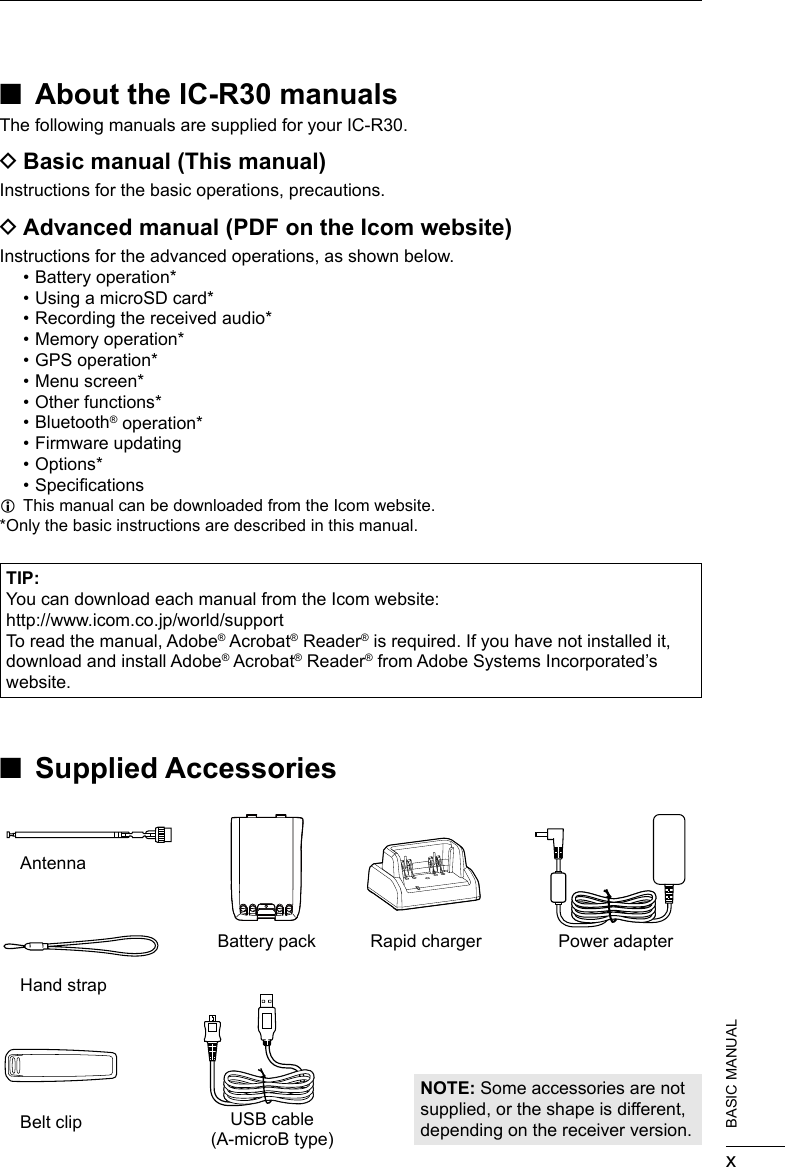
![41PREPARATION 1201802 201802BASIC MANUAL ■Inserting a microSD cardRefer to page 23 for the usable microSD card.1. Turn OFF the receiver.2. Pull down the [microSD] slot cover on the side panel.3. With the terminals facing the front, insert the card into the slot until it locks in place and makes a ‘click’ sound. LWhen removing, push in the microSD card until a ‘click’ sounds. The card is unlocked, and you can pull it out.CAUTION: • DO NOT touch the card terminals. • DO NOT remove the card from the receiver while the card is being accessed. Otherwise, the card data may be corrupted or deleted. 4. Completely close the [microSD] slot cover.[microSD] slot microSD cardTerminals facing the frontSlot cover CAUTION: DO NOT forcibly or inversely insert the card. It will damage the card or the slot. ■Turning ON the receiver ■Adjusting an audio level zHold down [ ] for 1 second to turn ON the receiver. • After the opening message and the remaining battery capacity are displayed, the receiving frequency is displayed. zHold down [ ] for 1 second again to turn OFF the receiver. zPush [▲] or [▼] to adjust an audio level. LThe display shows the volume level while adjusting. LContinuously holding down [▲] or [▼] quickly adjusts the level. LWhen “ ” is displayed, the functions assigned to [DIAL] and [▲]/[▼] are swapped. In this case, rotate [DIAL] to adjust the level.[ ][▲] [▼]](https://usermanual.wiki/ICOM-orporated/375410/User-Guide-3847850-Page-17.png)
![51PREPARATION201802BASIC MANUAL ■ Saving a setting data onto a microSD cardYou can save the Memory channels, Menu screen item settings, and GPS memories on a microSD card. Saving settings on a card enables you to easily restore the receiver to its previous settings, even if you perform an All Reset. DFormatting the microSD cardIMPORTANT! Before using a microSD card, format the card using the receiver. L Formatting a card deletes all its data. Before formatting any used card, back up its data onto your PC.[MENU] > SD Card > Format 1. Turn ON the receiver. LIf a microSD card is inserted, “ ” is displayed. LWhen accessing, “ ” and “ ” alternately blink.2. Push [MENU].3. Select “Format” in the “SD Card” menu. (Rotate [DIAL] to select it, and then push [ENTER].) • A conrmation dialog is displayed.4. Select “YES,” and then push [ENTER]. • The formatting starts and the display shows the formatting progress. • After the formatting ends, returns to the MENU screen. L If “The GPS Logger function is activated.” is displayed, turn OFF the function (p. 42) or ignore the message and select “YES.”5. Push [CLEAR] to return to the Main screen.](https://usermanual.wiki/ICOM-orporated/375410/User-Guide-3847850-Page-18.png)
![61PREPARATION 1201802 201802BASIC MANUAL DSaving a setting data[MENU] > SD Card > Save Setting1. Push [MENU].2. Select “Save setting” in the “SD Card” menu. (Rotate [DIAL] to select it, and then push [ENTER].)3. Select “<<New File>>,” and then push [ENTER]. LThe le name is automatically named in the following manner: Setyyyymmdd_xx (yyyy: Year, mm: month, dd: day, xx: serial number). 4. Push [ENTER] to set the file name. • A conrmation dialog is displayed.5. Select “YES,” and then push [ENTER]. • While saving, a progress bar is displayed, then returns to the SD CARD screen after the saving is completed.6. Push [CLEAR] to return to the Main screen.TIP: You can edit the saved settings on your PC using the optional CS-R30 cloning software.](https://usermanual.wiki/ICOM-orporated/375410/User-Guide-3847850-Page-19.png)
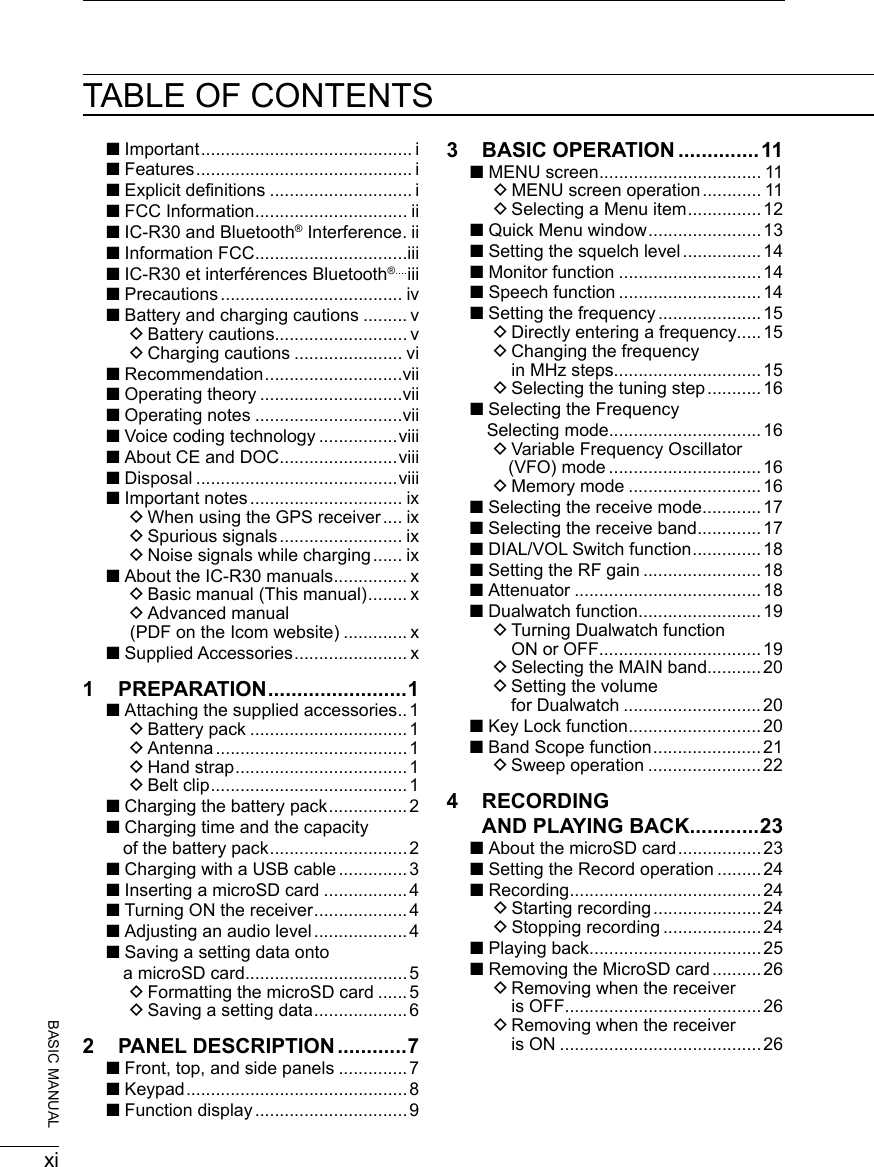
![2018027BASIC MANUAL2PANEL DESCRIPTION ■Front, top, and side panels1SQUELCH ADJUSTMENT KEY [SQL] zWhile pushing, rotate [DIAL] to adjust the squelch level. (p. 14) zPush or hold down to turn the Monitor function ON or OFF. (p. 14)2VOLUME ADJUSTMENT KEYS [▲][▼] Push to adjust the audio volume level.3POWER/SPEECH KEY [ ]/[SPEECH] zPush to turn the Speech function ON or OFF. (p. 14) zHold down for 1 second to turn the receiver ON or OFF.4microSD CARD SLOT Accepts a microSD card (User supplied). (p. 23)5ANTENNA CONNECTOR Connect the supplied antenna.6DIRECTIONAL PAD D-Pad (Up)/D-Pad (Down)/D-Pad (Left)/D-Pad (Right) Push to select a menu item, setting, and so on. (p. 49)7MAIN/DUAL KEY [MAIN]/[DUAL] zPush to set the A or B band as the main band. (p. 19) zHold down for 1 second to turn the Dualwatch function ON or OFF. (p. 19)8MENU/ENTER KEY [MENU]/[ENTER] zPush to enter the Menu screen. zPush to set the entered data or selected item.123456789**Function display (p. 9)Keypad(p. 8)Speaker*Close the cover rmly when no in use.](https://usermanual.wiki/ICOM-orporated/375410/User-Guide-3847850-Page-20.png)
![82PANEL DESCRIPTION 2201802 201802BASIC MANUAL9TUNING DIAL [DIAL] Rotate to set the frequency, select a Memory channel, a menu item, or enter characters. (pp. 15, 27 and 49)QUICK/LOCK KEY [QUICK]/[ ] zPush to enter or exit the Quick Menu screen. (p. 13) zHold down for 1 second to activate the Key Lock function. (p. 20)VFO/MEMORY/CLEAR KEY [VFO]/[MR]/[CLEAR] zPush to select the VFO mode or Memory mode. (p. 16) zPush to cancel the entered data, selected item, exit the current mode, or return to the previous screen.SPEAKER JACK Connects to a 3.5 mm (1/8 inch) external speaker plug.USB (Micro-B) CONNECTOR Connects to a PC using the supplied USB cable. (p. 3) ■Keypad zPush to set the frequency in the VFO mode. (p. 16) zPush or hold down to use the functions listed below.KEYS PUSH HOLD DOWN[1]/[BAND] Selects a band in the VFO mode, or selects a group in the Memory mode.[2]/[MHz] Turns the MHz tuning mode ON or OFF (VFO Mode).[3]/[MODE] Displays the Receive mode options.[4]/[SCAN] Displays the Scan type options. Starts the last selected scan.[5]/[SCOPE] Displays the Sweep type options.[6]/[SKIP] Displays the Skip/Program Skip options (in the Memory mode). [7]/[ATT] Displays the Attenuator options.[8]/[MW] Displays the Memory Write options.Writes memory to the selected channel. [9]/[TS] Displays the Tuning step options.[.]/[DIAL SEL] Changes the functions assigned to [DIAL] and [▲]/[▼].[0]/[●REC] Starts or stops the voice recording.[F-INP] Displays the Frequency Setting screen.](https://usermanual.wiki/ICOM-orporated/375410/User-Guide-3847850-Page-21.png)
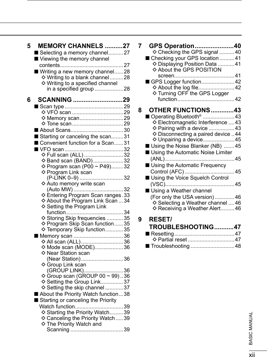
![92PANEL DESCRIPTION201802BASIC MANUAL1BATTERY INDICATOR Displays the battery status. (p. 2)2Bluetooth® ICON Displayed when a Bluetooth device is connected. (p. 43)3GPS ICON Displays satellite acquisition status. (p. 40)4GPS ALARM ICON Blinks when the GPS Alarm sounds. See ADVANCED MANUAL for details.5microSD CARD ICON (p. 23) zDisplayed when a microSD card is inserted. zBlinks while the receiver is accessing a microSD card.6VOLUME/DIAL SWITCH ICON Displayed when the Volume Adjustment function is assigned to [DIAL]. L “SQL” is displayed while adjusting the squelch.7DUPLEX INDICATOR z “DUP+”: Displayed when Plus duplex is selected. z“DUP– ”: Displayed when Minus duplex is selected.8AUTO POWER OFF ICON Displayed when the Auto Power OFF function is ON.9RECORD ICON (p. 24) z“”: Displayed when recording z“”: Displayed when recording is paused.CLOCK READOUT Displays the current time.ATTENUATOR INDICATOR Displayed when attenuator “ATT1” ~ “ATT3” is ON.RF GAIN INDICATOR Displayed when the RF gain is set to other than “RFG MAX” to indicate that the RF gain is reduced. ■Function display123456 789Dual band display (Dualwatch function is ON)Single band display(Dualwatch function is OFF)(These screens are only examples.)](https://usermanual.wiki/ICOM-orporated/375410/User-Guide-3847850-Page-22.png)
![102PANEL DESCRIPTION 2201802 201802BASIC MANUALMUTE ICON Displayed when the sub band audio signal is muted, depending on the receive band or mode. (p. 19)AFC ICON Displayed when the Automatic Frequency Control function is ON. (p. 45)PRIORITY ICON Displayed during a Priority watch. (p. 38)SKIP INDICATOR (p. 37) z“SKIP”: Displayed when Memory Skip is set. z“PSKIP”: Displayed when Program Skip is set.MEMORY CHANNEL READOUT Displays the selected memory channel number.MEMORY MODE ICON Displayed when the Memory mode is selected. (p. 16)SCRAMBLER/ENCRYPTION INDICATOR z“SCRM”: Displayed when the Descrambler function is ON. z“ENCR”: The Decryption function is ON.NOISE BLANKER ICON Displayed when the Noise Blanker function is ON. (p. 45)VSC INDICATOR Displayed when the Voice Squelch Control function is ON. (p. 45)AUTOMATIC NOISE LIMITER ICON Displayed when the Automatic Noise Limiter function is ON. (p. 45)S-METER Displays the relative signal strength of the receive signal.MEMORY NAME READOUT Displays the memory name, if entered.FREQUENCY READOUT Displays a variety of information, such as the frequency or menu contents.WX INDICATOR (For only the USA version.) Displayed when the Weather Alert function is ON. TONE/DIGITAL SQUELCH INDICATOR Displayed when a Tone/Digital squelch function is ON. zTSQL: Tone Squelch. zDTCS: DTCS Squelch. zTSQL-R: Reverse Tone Squelch. zDTCS-R: Reverse DTCS Squelch. zCSQL: Digital Code Squelch. (D-STAR) zNAC: Network Access Code (P25) zCOM ID: Common ID (dPMR) zCC: CC (dPMR) zRAN: Radio Access Number (NXDN-VN/NXDN-N) zUC: User Code (DCR)MODE INDICATOR Displays the selected receive mode.MAIN BAND ICON z When the Dualwatch function is ON, indicates that the selected band (A or B) is the Main band. z When the Dualwatch function is OFF, indicates the selected band (A or B).USB CONNECTION INDICATOR Displayed when a PC is connected through a USB cable, and “Serialport” is selected in the Menu screen. ( [MENU] > Function > USB Connect > Serialport)](https://usermanual.wiki/ICOM-orporated/375410/User-Guide-3847850-Page-23.png)
![20180211BASIC MANUAL3BASIC OPERATION ■MENU screenThe MENU screen is displayed after pushing [MENU].You can use the MENU screen to change settings.See the appendix for the MENU item list. (p. 49)For details of each item, see ADVANCED MANUAL.MENU screen structure DMENU screen operationTIP: The MENU screen is constructed in a tree structure. You may go to the next tree level, or go back a level, depending on the selected item.D-pad (Up)Selects an item or option.D-pad (Right)Goes to thenext tree level.D-pad (Left)Goes to the previous tree level.Closes the MENU screen.Opens the Quick Menu window. • Opens the MENU screen • Sets an option.Simplied description—‘Select’ operationIn this manual, user’s ‘Select’ operation is simplied, as described below.Simplied description: Select “Function,” and then push [ENTER].Operation: Push D-pad (Up) or (Down) to select “Function,” and then push [ENTER].D-pad (Down)Selects an item or option.](https://usermanual.wiki/ICOM-orporated/375410/User-Guide-3847850-Page-24.png)
![123BASIC OPERATION 3201802 201802BASIC MANUAL DSelecting a Menu itemExample: Set “Auto Power OFF” to “30 min.”[MENU] > Function > Auto Power OFF1. Push [MENU].2. Select “Auto Power OFF” in the “Function” menu. (Rotate [DIAL] to select it, and then push [ENTER].)3. Select “30min,” and then push [ENTER]. • Sets the option, then goes back to the previous tree level.4. Push [CLEAR] to return to the Main screen.TIP: To return to the default setting1. Push [QUICK] in step 3.2. Select “Default,” and then push [ENTER]. • The setting returns to the default. LThe default settings of each item are described in ADVANCED MANUAL.](https://usermanual.wiki/ICOM-orporated/375410/User-Guide-3847850-Page-25.png)
![133BASIC OPERATION201802BASIC MANUAL ■Quick Menu windowYou can open the Quick Menu window by pushing [QUICK]. Selectable items in the window may differ, depending on the selected mode or function. The items listed below are two examples.VFO mode Memory modeBand Select NB*6Group Select ANL*7MODE ANL*7MODE AFC*8DUP AFC*8DUP SKIPTONE*1GPS Information TONE*1GPS InformationVSC*2GPS Position VSC*2GPS PositionD.SQL*3PRIO Watch D.SQL*3Home CH SetSCRAM*4Home CH Set SCRAM*4Display TypeENCR*5Battery Level ENCR*5Battery LevelTS Band Scope TS Band ScopeATT <<REC Start>> ATT <<REC Start>>RF Gain<<GPS Logger Only>>RF Gain<<GPS Logger Only>>– – NB*6–*1 For only FM/FM-N*2 For only FM/FM-N/WFM/AM/AM-N*3 For only D-STAR/P25/dPMR/NXDN-VN/NXDN-N/DCR (Selectable options differ, depending on the receiving mode.)*4 For only dPMR*5 For only NXDN-VN/NXDN-N/DCR (Selectable options differ, depending on the receiving mode.)*6 For only USB/LSB/CW*7 For only AM*8 For only FM/FM-N/WFM[QUICK]Selectable items in the VFO mode and Memory mode](https://usermanual.wiki/ICOM-orporated/375410/User-Guide-3847850-Page-26.png)
![143BASIC OPERATION 3201802 201802BASIC MANUAL ■ Setting the squelch levelNoise squelch enables the audio to be heard only while receiving a signal that is stronger than the set level. A higher level blocks weak signals, which enables you to receive only stronger signals. A lower level enables you to hear weak signals. L“Noise squelch” is abbreviated to “Squelch” in this manual. While holding down [SQL], rotate [DIAL] to select the squelch level. • “ ” is displayed. LInformation • Options: “OPEN,” “AUTO” (default), and “LEVEL 1” ~ “LEVEL 9” • “LEVEL 1” is loose squelch (for weak signals) and “LEVEL 9” is tight squelch (for strong signals). • “AUTO” is an automatic level adjustment using a noise pulse counting system. • “OPEN” is the continuously open setting. • This option is not selectable in the Digital (D-STAR, P25, dPMR, NXDN-VN, NXDN-N, or DCR) mode.[DIAL][SQL] ■Monitor functionThe Monitor function is used to listen to weak signals without changing the squelch setting.While holding down [SQL], the receiver monitors weak signals on the frequency.TIP: You can set the Monitor Hold function on the MENU screen. The receiver opens or closes the squelch each time you push [SQL].([MENU] > Function > Monitor) The rst few segments of the S-meter blinks. ■Speech functionThe Speech function audibly announces the displayed frequency and mode by pushing [SPEECH]. Also, you can set various Speech functions, such as the DIAL Speech function or Mode Speech function on the MENU screen. ([MENU] > SPEECH > DIAL SPEECH)([MENU] > SPEECH > MODE SPEECH)[SPEECH]](https://usermanual.wiki/ICOM-orporated/375410/User-Guide-3847850-Page-27.png)
![153BASIC OPERATION201802BASIC MANUAL ■Setting the frequency DDirectly entering a frequencyYou can set the frequency with the keypad.1. Push [VFO/MR] to select the VFO mode.2. Push [F-INP].3. Start entry with the MHz digits. • When you nish entering the 1 kHz digit, a beep sounds and the entered frequency is set. LInformation • If you want to change the digits from 100 kHz or below, enter [.] and then enter the digits. • If you push [ENT] when the digits from 100 kHz or below are not entered, “0” is automatically entered into the blank digits. (Example: [1], [4], [5], [ENTER] → 145.000 (MHz)) • If you enter a frequency out of range, an error beep sounds. • Settable receiving bands differ on the A band and B band. (p. 17)Keypad[MHz] DChanging the frequency in MHz stepsYou can change the frequency in ‘MHz’ steps for quick tuning.1. Push [VFO/MR] to select the VFO mode.2. Push [MHz]. • The 1 MHz digit blinks.3. Rotate [DIAL]. • The frequency changes in 1 MHz steps.4. Push [MHz]. • Sets the frequency, and then returns to the Main screen.](https://usermanual.wiki/ICOM-orporated/375410/User-Guide-3847850-Page-28.png)
![163BASIC OPERATION 3201802 201802BASIC MANUAL DSelecting the tuning stepWhen you select the frequency by rotating [DIAL] in the VFO mode, it changes in the selected tuning step.1. Push [VFO/MR] to select the VFO mode.2. Push [TS].3. Select a tuning step. (Rotate [DIAL] to select it, and then push [ENTER].)4. Push [TS]. • Returns to the Main screen.*1 For only the AIR band. *2 For only the BC band.This receiver has 2 Frequency Selecting modes. You can change modes by pushing [VFO/MR]. 0.01 kHz 12.5 kHz 0.1 kHz 15.0 kHz 1.0 kHz 20.0 kHz 3.125 kHz 25.0 kHz 5.0 kHz 30.0 kHz 6.25 kHz 50.0 kHz 8.33 kHz*1 100.0 kHz 9.0 kHz*2 125.0 kHz 10.0 kHz 200.0 kHz ■Selecting the Frequency Selecting modeVFO mode displayMemory mode display DVariable Frequency Oscillator (VFO) modeYou can set the frequency by rotating [DIAL], or by directly entering it with the keypad. DMemory modeYou can set the frequency by selecting a preset channel, using [DIAL] or keypad. L In the Memory mode, “MR” and Memory Channel number are displayed.](https://usermanual.wiki/ICOM-orporated/375410/User-Guide-3847850-Page-29.png)
![173BASIC OPERATION201802BASIC MANUAL ■Selecting the receive mode1. Push [MODE]. • The Receive Mode options are displayed.2. Select the Receive mode. • The selected mode is displayed.NOTE:Selectable receive mode differs, depending on the band. • A band (1300 MHz and below): All modes*. • A band (1300 MHz or higher): FM/FM-N/WFM/AM/AM-N. • B band: FM/FM-N/AM/AM-N/Digital modes.* “WFM” is not selectable, depending on the receiver version and receive frequency.FMAnalog modeFM-NWFMAMAM-NLSBUSBCWCW-RD-STARDigital modeP25dPMRNXDN-VNNXDN-NDCR ■Selecting the receive band1. Push [VFO/MR] to select the VFO mode.2. Push [BAND]. • The Receive Band options are displayed. • The frequency set last time is displayed.3. Select the Receive band. • The selected band is displayed.[BAND] L On the B band, you can select only AIR, 146 MHz, 370 MHz, and 440 MHz bands.Default display Band name1.620 BC band5.000 5 MHz band51.000 51 MHz band88.000 FM band120.000 AIR band146.010 146 MHz band370.000 370 MHz band440.000 440 MHz band850.000 850 MHz band1295.000 1200 MHz band2425.000 2400 MHz band](https://usermanual.wiki/ICOM-orporated/375410/User-Guide-3847850-Page-30.png)
![183BASIC OPERATION 3201802 201802BASIC MANUAL ■DIAL/VOL Switch functionYou can switch the functions assigned to [DIAL] and [▲]/[▼]. zPush [DIAL SEL] to switch the functions assigned to [DIAL] and [▲]/[▼]. LInformation • “ ” is displayed when the Volume Adjustment function is assigned to [DIAL]. • Push [DIAL SEL] again to return to the previous setting. • Even if the Volume Adjustment function is assigned to [DIAL], you can set a squelch level by using [DIAL]. • In this manual, all instructions are described without this setting. ■AttenuatorThe Attenuator prevents a desired signal from becoming distorted when a very strong signal is near the frequency, or when near a very strong electric eld.1. Push [ATT]. • The Attenuator options are displayed.2. Set the Attenuator level to between “ATT1” to “ATT3.” LThe higher the level, the larger the attenuation amount becomes.[DIAL SEL][ATT] ■Setting the RF gainSet the sensitivity level to receive. Normally, set the RF gain to maximum (“RFG MAX”).1. Push [QUICK].2. Select “RF Gain,” and then push [ENTER].3. Select the level. LOptions: “RFG1” ~ “RFG9” and “RFG MAX” (default) LWhen “RFG MAX” is selected, nothing is displayed.](https://usermanual.wiki/ICOM-orporated/375410/User-Guide-3847850-Page-31.png)
![193BASIC OPERATION201802BASIC MANUAL ■Dualwatch functionDualwatch function simultaneously monitors two frequencies. The IC-R30 has 2 independent receiver circuits, A band and B band. You can set different frequencies or receive modes in each band. LIn the A band, you can select any frequency. In the B band, you can select only the AIR, 146 M, 370 M, or 440 M frequency bands. LWhen the Dualwatch function is ON, the audio output may be interrupted when the frequency is switched while scanning, or by other factors. DTurning Dualwatch function ON or OFFHold down [DUAL] for 1 second to turn the Dualwatch function ON or OFF. LInformation • When the Dualwatch function is ON, the display shows the A band in the upper half and the B band in the lower half. • “MAIN” is displayed on the MAIN band where you can change the settings. • When the Dualwatch function is OFF, the display shows only the MAIN band. Push [MAIN] to select A or B band. • The SUB band can be automatically muted. ([MENU] > Sounds > Sub Band Mute (Main RX))Single band display(Dualwatch function OFF)TIP: Depending on the receive mode, the SUB band audio signal is muted. In such case, “ ” is displayed. • SUB band mute statusMAIN band SUB bandLSB/USBDigital modes*CW/CW-RDigital modes**Except when D-STAR is selected on the Dualwatch screen.Dual band display(Dualwatch function ON)MAIN bandSUB band](https://usermanual.wiki/ICOM-orporated/375410/User-Guide-3847850-Page-32.png)
![203BASIC OPERATION 3201802 201802BASIC MANUAL DSelecting the MAIN bandPush [MAIN] to alternately set the upper band or lower band to the MAIN band. • “MAIN” is displayed on the MAIN band where you can change the settings. LBand selection, receive frequency setting, receive mode selection, Memory channel selection, the Memory Write operation, the Band Scope operation can be made on only the MAIN band. DSetting the volume for DualwatchThe volume setting for Dualwatch can be separately set for each band on the MENU screen.[MENU] > Sounds > A/B Vol Link1. Push [MENU].2. Select “A/B Vol Link,” in the “Sounds” menu. (Rotate [DIAL] to select it, and then push [ENTER].)3. Select “A/B Separate,” and then push [ENTER]. LPush [CLEAR] to return to the Main screen. ■Key Lock functionActivate to prevent accidental frequency changes and unnecessary function access. zHold down [ ] for 1 second to turn ON the Key Lock function. • When the Key Lock function is ON and the locked key or [DIAL] is pushed or rotated, “LOCK ON” is displayed. LInformation • To turn OFF the function, hold down [LOCK] for 1 second again (Until “LOCK OFF” is displayed). • [ ], [ ], [SQL], and [▲]/[▼] (volume adjustment) can be used even if the Key Lock function is ON. • You can change the keys to be locked on the MENU screen. ([MENU] > Functions > Key Lock)[ ]B band is set to the MAIN band](https://usermanual.wiki/ICOM-orporated/375410/User-Guide-3847850-Page-33.png)
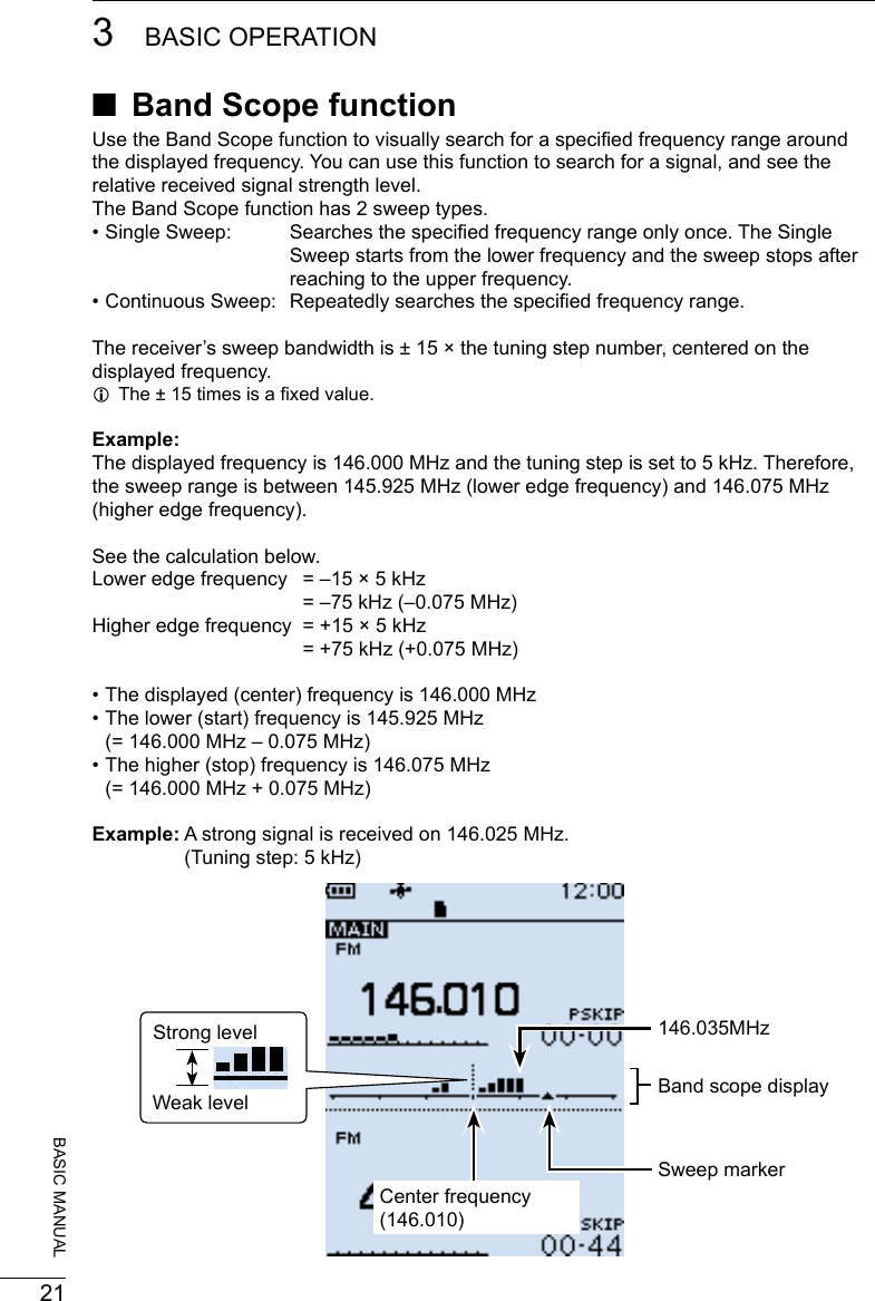
![223BASIC OPERATION 3201802 201802BASIC MANUAL DSweep operationExample: Continuous sweeps centered on 146.010 MHz1. Push [VFO/MR] to select the VFO mode.2. Rotate [DIAL] to set 146.010 MHz.3. Push [SCOPE].4. Select “Continuous Sweep.” (Rotate [DIAL] to select, and then push [ENTER].) • Returns to the frequency display and starts the continuous sweep.5. Push [CLEAR]. • Stops the sweep.6. Rotate [DIAL] to move the sweep marker to a detected signal. • You can hear the signal audio. LPushing [SCOPE] and then selecting “Center Recall” returns the sweep marker to the center frequency.7. Push [SCOPE].8. Select “Scope OFF,” and then push [ENTER]. • Turns OFF the Band Scope function.Sweeping After stopping the sweep, move the marker to a detected signal.TIP: • If the tuning step is set too wide, the signals in the sweep range may not be displayed (they may be skipped), even if they are strong signals. Therefore, we recommend that you set the tuning step to 20 kHz or less to use the Band Scope function. • During a sweep the frequency range of 108.000 ~ 520.000 MHz, the displayed frequency’s audio is output. (When the receive mode is set to WFM, LSB, USB, CW or CW-R, the audio is not output.) You can turn OFF the audio output on the MENU screen. ([MENU] > Sounds > Scope AF Output)[SCOPE]](https://usermanual.wiki/ICOM-orporated/375410/User-Guide-3847850-Page-35.png)
![244RECORDING AND PLAYING BACK 4201802 201802BASIC MANUAL ■Setting the Record operationYou can select to record the received audio from only the main band or both the main and sub bands.[MENU] > RX Recorder > Recorder Set > REC Operation1. Push [MENU].2. Select “REC Operation” in the “RX Recorder” menu. (Rotate [DIAL] to select it, and then push [ENTER].)3. Select “A/B Separate” or “A/B Link.” (default: A/B Link) “A/B Separate”: Only audio signal received on the band that is set as MAIN (A or B) is recorded. “A/B Link”: Audio signals received on either or both MAIN and SUB band (Both A and B) are recorded. LPush [CLEAR] to return to the Main screen. ■Recording DStarting recording zPush [zREC]. • “Recording started...” is briey displayed.TIP: • “ ” is displayed during recording. • “ ” is displayed while recording is paused. • If a single band display is selected, only the audio signal received on the band is recorded, even when the “REC Operation” item is set to “A/B Link.” • The recording continues until you push [zREC], or the free space on the microSD card has run out. • When the recording le’s content reaches 2 GB, the receiver continues to record, but to a new le. DStopping recording1. Push [zREC] again. • A conrmation dialog is displayed.2. Select “YES,” and then push [ENTER]. • “Recording stopped.” is briey displayed.NOTE: Once the recording starts, it will continue even if the receiver is turned OFF and ON again.TIP:As the default setting, the recording is paused while the squelch is closed, and resumes when a signal is received. But you can set to continue recording even while no signal is received. (See section 6 of the ADVANCED MANUAL.)([MENU] > RX Recorder > Recorder Set > RX REC Condition)[zREC]](https://usermanual.wiki/ICOM-orporated/375410/User-Guide-3847850-Page-37.png)
![254RECORDING AND PLAYING BACK201802BASIC MANUAL ■Playing back[MENU] > RX Recorder > Play Files1. Push [MENU].2. Select “Play Files” in the “RX Recorder” menu. (Rotate [DIAL] to select it, and then push [ENTER].) • The folder list is displayed.3. Select a folder that contains the file you want to playback, and then push [ENTER]. • The le list is displayed. LThe folder is named in the following manner, “yyyymmdd (yyyy: Year, mm: month, dd: day).4. Select a file, and then push [ENTER]. • The VOICE PLAYER screen appears and starts playing back the audio. LPush [ENTER] to pause while playing. LOn the VOICE PLAYER screen, you can select the le to play by pushing D-pad (Up) or (Down).5. Push [CLEAR] to stop playing. • The le list is displayed. LPush [CLEAR] again to return to the Main screen.](https://usermanual.wiki/ICOM-orporated/375410/User-Guide-3847850-Page-38.png)
![264RECORDING AND PLAYING BACK 4201802 201802BASIC MANUAL ■Removing the MicroSD card DRemoving when the receiver is OFF1. Turn OFF the receiver.2. Pull down the [microSD] card slot cover.3. Push in the microSD card into the slot until a click sounds. • The card is unlocked, and you can pull it out. LDo not touch the contacts of the card.4. Close the [microSD] card slot cover. DRemoving when the receiver is ON[MENU] > SD card > Unmount1. Push [MENU].2. Select “Unmount” in the “SD Card” menu. (Rotate [DIAL] to select it, and then push [ENTER].) • The unmount conrmation dialog appears.3. Select “YES,” and then push [ENTER]. • “Unmount is completed.” is displayed.4. Push in the microSD card until a click sounds, then pull it out. (See the above illustration.) LPush [CLEAR] to return to the Main screen.NOTE: Close the microSD card slot cover rmly, after removing or inserting microSD card.Otherwise dust or water may get into the receiver, and they can damage the receiver.Close the slot cover rmlyYES NO](https://usermanual.wiki/ICOM-orporated/375410/User-Guide-3847850-Page-39.png)
![20180227BASIC MANUAL5MEMORY CHANNELS ■Selecting a memory channelRotate [DIAL] in the Memory mode to select a Memory channel. LThe memory contents on the screen may differ, according to the presetting. 1. Push [VFO/MR] to select the Memory mode. LEach push toggles between the Memory mode and the VFO mode. LPush [BAND] to display the Memory Group list, if necessary to select a group.2. Rotate [DIAL] to select a Memory channel. LOnly the Memory channels that have contents are displayed. LTo select the Memory channel from the keypad, push [F-INP] then enter the Memory channel number. ■Viewing the memory channel contentsYou can view the Memory channel contents on the [Manage Memory] screen.[MENU] > Manage Memory > Memory ChannelExample: Viewing the contents of Channel 8 in Group 00.1. Push [MENU].2. Select “Manage Memory.” (Rotate [DIAL] to select it, and then push [ENTER].)3. Select Memory Channel Group “00,” and then push [ENTER].4. Select Memory Channel “08,” and then push [ENTER]. • Channel contents are displayed. LRotate [DIAL] to scroll the screen. LPush [CLEAR] to return to the Main screen.Group list List of Memory Channels in Group 00Contents of Memory Channel 08](https://usermanual.wiki/ICOM-orporated/375410/User-Guide-3847850-Page-40.png)
![285MEMORY CHANNELS 5201802 201802BASIC MANUAL ■Writing a new memory channelA single memory channel stores the frequency, receive mode and so on, for quick recall.The following is the basic memory writing procedure. LRefer to ADVANCED MANUAL for memory writing details. LSee Section 3 for the receive frequency or receiving mode setting procedures. DWriting to a blank channelExample: Writing “145.000 MHz” in the “FM” mode to a blank channel in a selected group. zHold down [MW] until 2 beeps sound. • The contents such as frequency and operating mode are briey displayed, then written to a blank channel (45) in the selected group (00). DWriting to a specied channel in a specied groupExample: Writing “145.100 MHz” in the “FM” mode into channel 01 in group 55.1. Push [MW].2. Select “Write to New CH.” (Rotate [DIAL] to select it, and then push [ENTER].)3. Push [QUICK].4. Select “Group Select,” and then push [ENTER].5. Select group “55,” and then push [ENTER].6. Rotate [DIAL] to select channel “01.” • The selected channel blinks.7. Push [MW]. • The writing conrmation dialog appears.8. Select “YES.” • The contents to be written into the channel are briey displayed, then are written into channel “01” in group “55.”[MW]Contents to be writtenMemory group to belong](https://usermanual.wiki/ICOM-orporated/375410/User-Guide-3847850-Page-41.png)
![20180229BASIC MANUAL6SCANNING ■Scan typeScanning is a versatile function that can automatically search for signals. A scan makes it easier to locate stations to listen to, or to skip unwanted channels or frequencies. DVFO scan (p. 32)In the VFO mode, the VFO scan searches a signal within the specied frequency range.Scan type DescriptionAuto MW When a signal is received during a VFO scan, the frequency is automatically stored into an Auto Memory Write channel group (A000 ~ A199).ALL Repeatedly scans the entire frequency range.BAND Repeatedly scans the selected band.P-LINK 0 ~ 9 Sequentially scans several Program Scan ranges.The links are set on the MENU screen. ([MENU] > Scan > Program Link)P00 ~ 49 Repeatedly scans the Program Scan range.The scan edges are set on the Menu screen.([MENU] > Scan > P-Scan Edge) DMemory scan (p. 36)In the memory mode, the memory scan searches a signal on the preregistered memory channels.Scan type DescriptionALL Scans all Memory channels.Mode Scans Memory channels which are entered with the same receiving mode as the currently selected mode.Near Station Searches for near stations that are within 160 kilometer (100 miles) from your location using your GPS position and the station’s position that is entered in the memory channels.GROUP LINK Sequentially scans the memory groups which are set to link on the MENU screen.GROUP Scans the Memory channels in the selected group.(GROUP 00 ~ 99, A: Auto MW CH, S: SKIP CH) DTone scanThe Tone scan searches for signals in tone frequencies or DTCS codes that are used by stations using the Tone Squelch function.See ADVANCED MANUAL for its operation. LA Tone scan is usable in either VFO or Memory channel mode. LDuring a scan, rotate [DIAL] to change the scan direction. See “Tone squelch operation” or “DTCS code squelch operation” for details on ADVANCED MANUAL.](https://usermanual.wiki/ICOM-orporated/375410/User-Guide-3847850-Page-42.png)
![306SCANNING 6201802 201802BASIC MANUAL ■About Scans [DIAL] operation during a scan • Rotate [DIAL] to change the scan direction during a scan. • When the scan is paused, rotate [DIAL] to resume the scan. Squelch setting for a scanYou can change the squelch level to suit your operating needs. Set the squelch level to open the squelch, according to the received signal strength. LDuring a scan, rotate [DIAL] while holding down [SQL] to adjust the squelch level. The scan resumes after adjusting. Tuning step for a VFO scanThe selected tuning step is applied to the scan.For a Program scan or Program Link scan, set the tuning step in the Program Scan ranges (P-Scan Edge). Scan Skip function*The skip function speeds up scanning by not scanning those frequencies set as skip channels.In the VFO modeThe frequencies that are set as “PSKIP” are skipped during a scan. (p. 37)In the Memory modeThe frequencies that are set as skip channels “PSKIP” and “SKIP” are not scanned. (p. 37) LYou must enter 2 or more Memory channels to start a memory scan.TIP: When Program Skip is set to OFF, you cannot use the Program Skip scan function. (p. 35)([MENU] > Scan > Program Skip) Receiving mode during a scan • The VFO scan uses the selected receiving mode. • During a Memory mode scan, the receiving mode entered into the channel is used. When signal is receivedWhen a signal is received, the scan pauses for this set period of time. When a received signal disappears, the scan resumes for this set period of time.[MENU] > Scan > Pause Timer[MENU] > Scan > Resume Timer1. Push [MENU].2. Select “Pause Timer” or “Resume Timer” in the “Scan” menu.3. Select an option, and then push [ENTER]. Pause Timer* • 2 ~ 20 sec: When a signal is received, the scan pauses for 2 ~ 20 seconds (in 2 second steps). • HOLD: The scan pauses on a received signal until the signal disappears. Resume Timer* • 0 sec: The scan resumes immediately after the signal disappears. • 1 ~ 5 sec: The scan resumes 1 ~ 5 seconds after the signal disappears. • HOLD: The scan remains paused for the Pause Timer setting, even if the signal disappears.NOTE: Rotate [DIAL] to resume the scan. The Resume Timer must be set shorter than the Pause Timer, otherwise this timer does not work properly.* These settings can be separately set to A band and B band.](https://usermanual.wiki/ICOM-orporated/375410/User-Guide-3847850-Page-43.png)
![316SCANNING201802BASIC MANUAL ■Starting or canceling the scanVFO scan: Select the VFO mode and operating mode.Memory scan: Select memory mode.1. Push [SCAN]. • Opens the Scan Type list window. LIf you hold down [SCAN] for 1 second, the last selected scan starts.2. Select a scan type. (Rotate [DIAL] to select it, and then push [ENTER].) LInformation • In the VFO mode, the decimal point and the selected Scan Type icon blink. • In the Memory mode the decimal point and the Memory icon blink. • During a scan: - Rotate [DIAL] to change the scanning direction. - Push [SCAN] to cancel the scan.[SCAN] ■Convenient function for a ScanIf the Skip setting is set, specied frequencies or memory channels will be skipped during the scan. • Skip setting for a VFO scan (p. 35) • Skip setting for a memory channel scan (p. 37) • Temporary skip setting (p. 35)Scan resume setting (p. 30)Voice Squelch Control (VSC) function (p. 45)VFO scan list Memory scan list](https://usermanual.wiki/ICOM-orporated/375410/User-Guide-3847850-Page-44.png)
![326SCANNING 6201802 201802BASIC MANUAL ■VFO scanThe VFO scan searches for a signal within the specied frequency range. LSee page 31 for details of ‘Starting or canceling the scan.’ DFull scan (ALL)Repeatedly scans the entire band.IC-R30 frequencylower endIC-R30 frequencyupper endScanJumpPSKIPPSKIP DBand scan (BAND)Repeatedly scans the selected band.Band frequencylower endBand frequencyupper endScanJumpPSKIPPSKIP DProgram scan (P00 ~ P49)Repeatedly scans the selected Program Scan range (P-Scan Edge 00 ~ 49). ScanJumpJumpScan rangeLower edge Upper edgePSKIPPSKIP At least one Program Scan range (P-Scan Edges) must be entered to start a Program scan.([MENU] > Scan > P-Scan Edge)See page 33 for more details. DProgram Link scan (P-LINK 0 ~ 9)Sequentially scans the Program Scan ranges. The links are set on the MENU screen. ([MENU] > Scan > Program Link)See page 34 for more details.Program scan edges (Example: P00 ~ P10)JumpScanP00 P01 P02 P03 P10 LWhile scanning, push [BAND] to move to the next Program scan range. DAuto memory write scan (Auto MW)When a signal is received during a VFO scan, the frequency is automatically stored into an Auto Memory Write channel group (A000 ~ A199).ScanSignal receivedJumpScan rangeA000ChannelsA002A001A199 LInformation • The Auto Memory Write scan writes to a memory channel when the scan automatically resumes. • When no blank channels is left in the Auto Memory Write channel group A (000 ~ 199), the scan automatically cancels. • When you start this scan, you can skip the following dialog in the Menu screen. “ Clear All memories in the group A? (The Auto MW Scan will then start.)( [MENU] > Scan > Auto MW SCAN Memory Clear)OFF: Writes to a blank channel in the group A.Display Dialog: Display dialog to conrm. ON: Clears all memories in the group A.](https://usermanual.wiki/ICOM-orporated/375410/User-Guide-3847850-Page-45.png)
![336SCANNING201802BASIC MANUAL DEntering Program Scan rangesYou can enter the upper and lower frequency edges for a Program scan.Each Program Scan range has its own tuning step, operating mode, and RF gain setting.You can enter up to 50 Program Scan ranges (P-Scan Edge) on the MENU screen.[MENU] > Scan > P-Scan Edge1. Push [MENU].2. Select “P-Scan Edge” in the “Scan” menu. (Rotate [DIAL] to select it, and then push [ENTER].)3. Select a blank Program scan range “00” ~ “49.”4. After pushing [QUICK], select “Edit” and then push [ENTER]. • The “P-Scan Edge” screen is displayed.5. Select “FREQ LOW” or “FREQ HIGH” to enter the lower edge and higher edge, and then push [ENTER]. LInformation • Rotate [DIAL] to select the item, and push [ENTER] to enter the edit screen. • Enter the lower edge and higher edge using the keypad. • When the “NAME” is entered, it displays on the Scan Type list window. About editing character, see ADVANCED MANUAL for details. • When the “TS” (Tuning Step), “MODE” and/or “RF GAIN” are blanked, they are used the current setting on the VFO mode. The “TS” and “MODE” must be set to match with you desired signals, if you are not familiar with them, we recommend to set them to “Auto.”6. After editing contents, select “<<Write>>,” and then push [ENTER]. • The conrmation dialog is displayed7. Select “YES,” and then push [ENTER]. LPush [CLEAR] to return to the Main screen.P-Scan Edge screenTIP: Clearing a Program scan rangeTo clear the Program scan range, select “Clear” at above step 4, and then push [ENTER]. • The conrmation window is displayed, select “YES” and push [ENTER] to clear the Program scan range.](https://usermanual.wiki/ICOM-orporated/375410/User-Guide-3847850-Page-46.png)
![346SCANNING 6201802 201802BASIC MANUAL DAbout the Program Link ScanThis item sets the Link function for 2 or more Program Scan range to sequentially scan during a Program Link scan. The Program Link scan scans all frequencies in the scan ranges.Default settings of the Program Link...Program Link 0:1:9:Edit Name00: 430.000−450.000Program Link number (0 to 9)BlankProgram Scan range (PXX)DeleteProgram Scan lower edge Program Scan upper edge LInformation • The Program Link Number screen displays the frequency range. • You can add a Link setting by pushing [QUICK] when 2 or more Program Scan ranges (P-Scan Edge) are entered. • When there is no Program Scan range (P00 ~ P49) entered, “Add” is not displayed after pushing [QUICK]. DSetting the Program Link function[MENU] > Scan > Program Link1. Push [MENU].2. Select “Program Link” in the “Scan” menu. (Rotate [DIAL] to select it, and then push [ENTER].)3. Select a Program Link number “0” ~ “9,” and then push [ENTER]. • The Program Link Number screen displays the preregistered Program Scan Ranges.4. After pushing [QUICK], select “Add” and then push [ENTER].5. Select the Program scan range that you want to add. (Rotate [DIAL] to select it, and then push [ENTER].)6. Repeat steps 4 and 5 until all Program scan ranges that you want, are added.7. Push [ENTER] to save the Program Link. LPush [CLEAR] to return to the Main screen. LWhen no Program scan range is selected, “-- No Edge --” is displayed.](https://usermanual.wiki/ICOM-orporated/375410/User-Guide-3847850-Page-47.png)
![356SCANNING201802BASIC MANUAL DStoring Skip frequenciesYou can skip unnecessary frequencies during a scan.While a scan is paused and if you want to skip the frequency, you can store it into the Skip channel group S (00 ~ 99) as a Skip channel (PSKIP). The Scan Skip function speeds up a scan.1. Start a VFO scan. • When a signal is received, the scan pauses.2. Hold down [SKIP] until two short beeps sound. • The frequency is stored into the Skip channels group. • The entered Memory channel number blinks. • After storing, the scan resumes. LIf there is no blank channel, an error beep sounds, and the frequency is not stored. DProgram Skip Scan functionThis function enables the receiver to skip the unwanted frequencies that are entered as Memory channels and are set to “PSKIP.” (p. 37)[MENU] > Scan > Program Skip1. Push [MENU].2. Select “Program Skip” in the “Scan” menu. (Rotate [DIAL] to select it, and then push [ENTER].)3. Select the Program Skip function, “ON” or “OFF,” and then push [ENTER]. • When “ON” is selected,“PSKIP” is displayed above the Memory channel number. LPush [CLEAR] to return to the Main screen. DTemporary Skip functionThis function temporarily skips unwanted frequencies (or memory channels) during a scan for the set period of time, without changing the Skip Channel setting. LYou can change Temporary Skip Timer on the MENU screen. (Default: 5 min) ([MENU] > Scan > Temporary Skip Timer)1. Start a scan. • When a signal is received, the scan pauses.2. After pushing [QUICK], select “Temporary Skip” and then push [ENTER]. • The scan automatically resumes. LAfter the Temporary Skip Timer period ends, the scan is canceled or the receiver is turned OFF, the Temporary Skip function is turned OFF.[SKIP]ONOFFTIP: • Up to 5 Temporary Skip frequencies or Memory channels can be set. When the 6th frequency or Memory channel is set, the oldest setting is automatically deleted.](https://usermanual.wiki/ICOM-orporated/375410/User-Guide-3847850-Page-48.png)
![366SCANNING 6201802 201802BASIC MANUAL ■Memory scanThe Memory scan searches a signal on the preregistered memory channels. LSee page 31 for details of ‘Starting or canceling the scan.’ DAll scan (ALL)Repeatedly scans all memory channels.00 01 02 99 A S03ScanMemory Groups(00 ~ 99, A: Auto MW CH and S: Skip CH)Empty groups are skippedJump DMode scan (MODE)Scans Memory channels which are entered with the same receiving mode as the currently selected mode. LThe Mode scan scans all memory groups. ( Group 00 ~ 99, A: Auto MW CH, S: SKIP CH)AM FM AM AM AMCWScanExample: Scanning AM mode Memory group 02Modes other than AM are skipped DNear Station scan (Near Station)Searches for up to 50 nearby stations that are within 160 kilometer (100 miles) from your location using your GPS position data and the station’s position data that is entered in the memory channels. LRegardless of the SKIP setting, all memory channels will be scanned.NOTE: • When using the Near Station scan, BE SURE to rst receive your own position data, or manually enter your position data. ([MENU] > GPS > GPS Set > GPS Select) • If no station is found within a 160 kilometer (100 miles) range, “No station found.” is displayed. • If the last received position data can be used, “GPS is invalid. Search by last valid position” is displayed. DGroup Link scan (GROUP LINK)Sequentially scans the memory groups that are set to link on the MENU screen.01 0200 A S99ScanMemory Groups(00 ~ 99, A: Auto MW CH and S: Skip CH)Unchecked groups are skipped Jump At least 2 groups must be checked to start a Group Link scan. ([MENU] > Scan > Group Link)See page 37 for more details. DGroup scan (GROUP 00 ~ 99)Scans the Memory channels in the selected group. (GROUP 00 ~ 99, A: Auto MW CH, S: SKIP CH)](https://usermanual.wiki/ICOM-orporated/375410/User-Guide-3847850-Page-49.png)
![376SCANNING201802BASIC MANUAL DSetting the Group LinkYou can sequentially scan the memory groups which are set to link on the MENU screen. LIn the default setting, all groups are set to link.[MENU] > Scan > Group Link1. Push [MENU].2. Select “Group Link” in the “Scan” menu. (Rotate [DIAL] to select it, and then push [ENTER].)3. Select a group, “00” ~ “99,” “A: Auto MW CH,” “S: SKIP CH.” 4. Push [ENTER] to turn the Link function ON or OFF. • Display “✔” when the function is set to “ON”. LPush [QUICK] to quickly turn all the groups ON or OFF. LIn the default setting, all groups are set to ON. LPush [CLEAR] to return to the Main screen. Group Link screen DSetting the skip channelYou can set or clear a Skip Channel setting.The channels that are set as a Skip channel are skipped during a scan.[MENU] > Manage Memory > (Group number)1. Push [MENU].2. Select the Group number in the “Memory Manage” menu. (Rotate [DIAL] to select it, and then push [ENTER].) LGroup numbers are “00” ~ “99,” “A: Auto MW CH” and “S: SKIP CH.”3. Select the memory channel to be skipped.4. After pushing [QUICK], select “Edit” and then push [ENTER].5. Select “SKIP,” and then push [ENTER]. LSelect an option, and then push [ENTER]. • OFF: Cancels the Skip Channel setting. • SKIP: Skipped during a Memory scan. • PSKIP: Skipped during both VFO and Memory scans.6. Select “<<Overwrite>>,” and then push [ENTER]. • The conrmation dialog is displayed, select “YES” and push [ENTER] to save the Memory channel. • Select “NO” to just close the conrmation window. LPush [CLEAR] to return to the Main screen.Manage Memory screenTIP: In the Memory mode operation, you can change the SKIP setting by pushing [SKIP].](https://usermanual.wiki/ICOM-orporated/375410/User-Guide-3847850-Page-50.png)
![386SCANNING 6201802 201802BASIC MANUAL ■About the Priority Watch functionWhile operating in the VFO mode, or while in the VFO scan, the Priority watch function shortly checks for signals on a selected memory channel (frequency) every 5 seconds.There are 4 ways to use the Priority Watch function, as described below. LWhen the Dualwatch function is ON, you can independently scan on the MAIN band and SUB band. LWhile operating the Priority Watch function, you can change the Operating Band, frequency (using [DIAL]), receiving mode, and so on. Also you can start or cancel the VFO scan. The Priority Watch function is canceled when: • Starting the Band scope. (p. 21) • Either the [CLEAR], [MW], or [F-INP] keys is pushed. • The “PRIO OFF” is selected in the Quick menu.Watching a Priority channel while receiving in the VFO modeWatching a Priority channel while scanning in the VFO modeMemory scanning while receiving in the VFO modeMemory scanning while scanning in the VFO modeVFOfrequencyPrioritychannelReceiving for 5 secondsPrioritychannelVFO scanScanning for 5 secondsVFOfrequencyReceiving for 5 secondsSKIP00010299M-CHVFO scanScanning for 5 secondsSKIP00010299M-CH](https://usermanual.wiki/ICOM-orporated/375410/User-Guide-3847850-Page-51.png)
![396SCANNING201802BASIC MANUALYou can start or cancel any scans that are described on the previous page, in the same way. DStarting the Priority WatchTo start the Priority watch, select “ON” or “Bell,” as described below. • ON : When a signal is received on the Priority channel, the channel is automatically selected. • Bell : When a signal is received on the Priority channel, beeps sound and the “S” icon blinks.1. Select the Priority channel or Scan type in the Memory mode.2. Push [QUICK].3. Select “PRIO Watch” in the Quick menu. (Rotate [DIAL] to select it, and then push [ENTER].)4. Select the option. • “PRIO” is displayed. DCanceling the Priority Watch1. Push [QUICK].2. Select “PRIO Watch OFF” in the Quick menu. (Rotate [DIAL] to select it, and then push [ENTER].) • “PRIO” disappears. DThe Priority Watch and ScanningWhen you want to use the combination of the Priority Watch and a scan, you start a Memory scan rst, then start the Priority Watch, and a VFO scan in order.1. Start a Memory scan in the Memory mode.2. Start the Priority Watch. • “PRIO” is displayed.3. Start a VFO scan.[QUICK] ■Starting or canceling the Priority Watch functionWhen “ON” is selected• When a signal is received on the Memory channelWhen “Bell” is selected](https://usermanual.wiki/ICOM-orporated/375410/User-Guide-3847850-Page-52.png)
![407BASIC MANUAL7GPS OPERATIONNOTE: The built-in GPS receiver cannot calculate its location if it cannot receive signals from the GPS satellites. Refer to ADVANCED MANUAL for more details on the GPS function. DChecking the GPS signalYou can check the satellite acquisition status indicated by the GPS icon. • The GPS icon blinks when receiving. → → → • The GPS icon is displayed when the current location is correctly received. LThe time it takes to receive the GPS data may differ, depending on your location. LThe GPS icon is not displayed when “GPS Select” is set to “Manual.” ([MENU] > GPS > GPS Set > GPS Select)TIP: For the battery power savingWhen using the receiver in the same place, you can save the battery power by manually entering your location, or manually read the received GPS position into the MANUAL POSITION screen.1. Confirm is displayed. (See above)2. Select “Manual Position” in the “GPS” menu. ([MENU] > GPS > GPS Set > Manual Position)3. Push [QUICK], and then select “Capture From GPS” to read the received position into the Manual position.4. Push D-pad (Left) to return to the “GPS set” screen.5. Set “GPS Select” to “Manual.” ([MENU] > GPS > GPS Set > GPS Select) • The manual position is activated instead of the internal GPS.](https://usermanual.wiki/ICOM-orporated/375410/User-Guide-3847850-Page-53.png)
![417GPS OPERATION201802BASIC MANUALExample:GPS POSITION screen (MY)Your course heading is East.Your course heading.LatitudeLongitudeTimeGrid LocaterAltitudeDisplays My position(Where you are)Speed ■Checking your GPS locationYou can check your current location. DDisplaying Position Data1. Confirm is displayed.2. Push [QUICK].3. Select “GPS Position.” (Rotate [DIAL] to select it, and then push [ENTER].) • The GPS POSITION screen is displayed.4. Rotate [DIAL]. • Changes between the MY (My position), RX (Received position), MEM (GPS Memory position), or ALM (GPS Alarm position) screen. LPush [CLEAR] to return to the Main screen. DAbout the GPS POSITION screenGPS Memory position (MEM) screen](https://usermanual.wiki/ICOM-orporated/375410/User-Guide-3847850-Page-54.png)
![427GPS OPERATION 7201802 201802BASIC MANUAL ■GPS Logger functionThe GPS Logger function enables you to save the position data from a GPS receiver onto a microSD card as a log. The GPS Logger saves Latitude, Longitude, Altitude, Positioning state, Course, Speed, Date, and Time.If you use this GPS Logger while driving, you can check your driving history on a mapping application. DAbout the log leIf you have the log le imported into a mapping application, you can display your route as you move on the software map. LThe log les may not be compatible with all mapping applications. LSee ADVANCED MANUAL for details on copying the log les onto your PC.NOTE: • The GPS logger function requires a microSD card (User supplied). See pages 4 and 23 for details. • This function is turned ON as the default setting. Therefore when you insert a microSD card, this function continuously saves the position data from the GPS receiver, even if you turn OFF the receiver, then turn it ON again. To turn OFF the function, do the steps below. • When the microSD card is full, this function will automatically be paused. DTurning OFF the GPS Logger function [MENU] > GPS > GPS Logger > GPS Logger 1. Push [MENU].2. Select “GPS Logger” in the “GPS” menu. (Rotate [DIAL] to select it, and then push [ENTER].)3. Select “OFF,” and then push [ENTER]. • The GPS logger function is turned OFF. LPush [CLEAR] to return to the Main screen.](https://usermanual.wiki/ICOM-orporated/375410/User-Guide-3847850-Page-55.png)
![20180243BASIC MANUAL8OTHER FUNCTIONS ■Operating Bluetooth®The receiver has a built-in Bluetooth unit. You can connect Bluetooth headsets, or other Bluetooth devices. When you connect a Bluetooth headset to the receiver, you can wirelessly receive. LThe communication range of Bluetooth is approximately 10 meters (33 feet).NOTE: The Bluetooth communication range may vary, depending on the environment where you operate the device. DElectromagnetic InterferenceWhen you use a Bluetooth device, pay attention to the following:Bluetooth devices operate in the 2.4 GHz band. The 2.4 GHz band is also used by other devices, such as Wireless LAN products, microwave ovens, RFID systems, amateur radio stations, and so on.When using this device near such devices, interference may occur, causing a decrease in communication speed, and an unstable connection. In such cases, use this device away from the other devices, or stop using those devices. DPairing with a device LThese instructions describe pairing with the VS-3 Bluetooth® headset, as an example.1. Turning ON the Bluetooth function[MENU] > Bluetooth Set > Bluetooth1. Push [MENU].2. Select “Bluetooth” in the “Bluetooth Set” menu. (Rotate [DIAL] to select it, and then push [ENTER].)3. Select “ON,” and then push [ENTER]. LPush [CLEAR] to return to the Main screen.2. Entering the VS-3 Pairing mode LConrm the VS-3 is turned OFF, before entering the Pairing mode. zHold down the VS-3’s [PWR] button for 6 seconds. LA melody sounds when the VS-3 is turned ON. LThe LED alternatively blinks red and blue, and then the VS-3 enters the pairing mode.](https://usermanual.wiki/ICOM-orporated/375410/User-Guide-3847850-Page-56.png)
![448OTHER FUNCTIONS 8201802 201802BASIC MANUAL3. Pairing and connecting a Bluetooth headset[MENU] > Bluetooth Set > Pairing/Connect > Device Search1. Push [MENU].2. Select “Device Search” in the “Bluetooth Set” menu. (Rotate [DIAL] to select it, and then push [ENTER].)3. Select “Search Headset,” and then push [ENTER]. • The receiver starts searching for a headset.4. Select a headset to pair, and then push [ENTER]. • A conrmation dialog is displayed.5. Select “YES,” and then push [ENTER]. • “ ” is displayed if the headset is correctly connected. LPush [CLEAR] to return to the Main screen.TIP:Auto Connect functionThe receiver automatically connects to a paired Bluetooth device.[MENU] > Bluetooth Set > Auto ConnectRe-searching Bluetooth device“No Device Found” is displayed if the receiver could not found a Bluetooth device.1. Push [QUICK].2. Select “Re-search.” (Rotate [DIAL] to select it, and then push [ENTER].) DDisconnecting a paired deviceYou can disconnect a paired Bluetooth device if it is not being used.[MENU] > Bluetooth Set > Pairing/Connect1. Push [MENU].2. Select “Pairing/Connect” in the “Bluetooth Set” menu. (Rotate [DIAL] to select it, and then push [ENTER].) • Paired devices are displayed. L“” is displayed, if the device is connected.3. Select a device to disconnect, and then push [ENTER]. • A conrmation dialog is displayed.4. Select “YES,” and then push [ENTER]. • “ ” disappears. LPush [CLEAR] to return to the Main screen. LTo re-connect a device, select the device on the Paring list again.](https://usermanual.wiki/ICOM-orporated/375410/User-Guide-3847850-Page-57.png)
![458OTHER FUNCTIONS201802BASIC MANUAL ■Using the Noise Blanker (NB) The Noise blanker function eliminates pulse-type noise such as the noise from car ignitions. LThe function is usable in the LSB, USB, and CW modes.[QUICK] > NB ■Using the Automatic Noise Limiter (ANL)The Automatic Noise Limiter function reduces noise components while receiving. LThe function is usable in the AM and AM-N modes.[QUICK] > ANL ■Using the Automatic Frequency Control (AFC)The Automatic Noise Limiter function reduces noise components while receiving. LThe function is usable in the FM, FM-N, and WFM modes.[QUICK] > AFC ■Using the Voice Squelch Control (VSC)The Voice Squelch Control function opens the squelch, or stops a scan only when voice components are detected in the signal. It is convenient to receive only voice communications. LThe function is usable in the FM, FM-N, WFM, AM, and AM-N modes.[QUICK] > VSCNOTE: The VSC function is designed to not detect a continuous audio signal. When receiving a signal such as a radio broadcast program that contains a continuous audio signal, the received audio may be broken up. In such case, turn OFF the VSC function. ■Operating Bluetooth® DUnpairing a deviceBefore unpairing a connected headset or device, disconnect it.[MENU] > Bluetooth Set > Pairing/Connect1. Push [MENU].2. Select “Pairing/Connect” in the “Bluetooth Set” menu. (Rotate [DIAL] to select it, and then push [ENTER].) • Paired devices are displayed.3. Select a device to unpair, and then push [QUICK].4. Select “Delete,” and then push [ENTER]. • A conrmation dialog is displayed.5. Select “YES,” and then push [ENTER]. LPush [CLEAR] to return to the Main screen.](https://usermanual.wiki/ICOM-orporated/375410/User-Guide-3847850-Page-58.png)
![468OTHER FUNCTIONS 8201802 201802BASIC MANUAL ■Using a Weather channel (For only the USA version)The receiver has 10 preset Weather channels. You can use these channels to monitor broadcasts from the National Oceanographic and Atmospheric Administration (NOAA). The receiver automatically detects a Weather alert tone on the selected Weather channel, or while scanning. DSelecting a Weather channel[QUICK] > Weather CH1. Push [QUICK].2. Select “Weather CH.” (Rotate [DIAL] to select it, and then push [ENTER].) • A weather Channel is displayed.3. Rotate [DIAL] to select a Weather channel. LPush [SCAN] to start a Weather channel scan. LPush [CLEAR] to return to the Main screen. DReceiving a Weather AlertNOAA broadcast stations transmit weather alert tones before important weather announcements. When the Weather Alert function is ON, the selected weather channel is monitored every 5 seconds for an announcement. L When the alert is received, “WX” and “ALT” alternately blink.A WX Alert received on channel “01.”](https://usermanual.wiki/ICOM-orporated/375410/User-Guide-3847850-Page-59.png)
![20180247BASIC MANUAL9RESET/TROUBLESHOOTING ■ResettingOccasionally, erroneous information may be displayed. This may be caused by static electricity or by other factors.If this problem occurs, turn OFF the receiver. After waiting a few seconds, turn ON the receiver. If the problem still exists, perform a Partial reset, as described below.If the problem still exists after a Partial reset, perform an All reset.The resets affect the following:Partial reset Settings on the MENU screen, receive history log, operating settings in the VFO mode.All resetSettings on the MENU screen, receive history log, operating settings in the VFO mode, Memory channel contents, Programmable Scan edges and GPS memories.NOTE:An All reset clears all data and returns all settings to their factory defaults. Save memory channel contents, setting status, and so on, onto an SD card before doing an All reset. Refer to Section 7 of ADVANCED MANUAL for details. LThe Bluetooth paring list is not cleared by an All reset. DPartial resetA Partial reset resets operating settings to their default values. LThe following settings are not returned to their default values. • Memory channels • Programmable Scan edges • GPS memories [MENU] > Others > Reset > Partial Reset1. Push [MENU].2. Select “Partial Reset” in the “Others” menu. (Rotate [DIAL] to select it, and then push [ENTER].) • The conrmation dialog is displayed.3. Select “YES,” then push [ENTER]. • After resetting, the IC-R30 will automatically restart.](https://usermanual.wiki/ICOM-orporated/375410/User-Guide-3847850-Page-60.png)
![489RESET/TROUBLESHOOTING 9201802 201802BASIC MANUAL ■TroubleshootingThe following chart is designed to help you correct problems that are not equipment malfunctions. If you are unable to locate the cause of a problem, or solve it through the use of this chart, contact your nearest Icom Dealer or Service Center.PROBLEM POSSIBLE CAUSE SOLUTION REF.Receiver does not turn ON. • The battery pack/case is exhausted. • Bad connection of a battery pack/case. • The battery polarity is reversed. • Charge the battery pack, or replace the batteries. • Clean the battery terminals. • Check the polarity in the case.p. 2 – –No sound comes from the speaker. • Volume level is too low. • Earphone mode is ON. • The squelch is set too tight. • A Tone function (CTCSS, DTCS or Digital Squelch (D.SQL)) is activated. • An external speaker is connected to the [SP] jack. • A Bluetooth headset is connected. • Push [▲] to increase the level. • Set the “Earphone Mode” item to “OFF” on the MENU screen. • Set to the threshold level. • Turn OFF the Tone function. • Remove the external speaker. • Disconnect the headset.p. 4– p. 14p. 15 – p. 44Sensitivity is too low, and only strong signals are audible. • The attenuator is activated. • The RF gain is reduced. ( “RFG1” ~ “RFG9” is selected.) • The coaxial cable is not connected, or shorted. (When an external antenna is used.) • Turn OFF the attenuator. • Set the “RF Gain” item to the “RFG MAX” in the QUICK menu window. • Check the coaxial cable connection or replace with a new one.p. 18 p. 18 –Sensitivity is too low on the BC band (1 M). • Internal antenna is not selected. • Set the “Bar Antenna” item to “Use” on the MENU screen. –Audio in the SSB mode is unclear or distorted. • The incorrect sideband is selected. • Toggle between USB and LSB. p. 17The function of [DIAL] and [▲]/[▼] is swapped. • Functions assigned to [DIAL] and [▲]/[▼] are swapped. • Push [DIAL SEL] to switch the functions.p. 18Frequency cannot be set. • The Key Lock function is ON. • The Memory mode is selected. • Turn OFF the Key Lock function. • Push [VFO/MR] to select the VFO mode.p. 20 p. 16The displayed frequency is erroneous. • The CPU has malfunctioned. • External factors have caused a fault. • Reset the receiver. • Remove and reattach the battery pack or case.p. 47 p. 1A Program Scan does not start. • The Memory mode is selected. • The same frequency has been programmed in the scan edge channels “FREQ HIGH” and “FREQ LOW.” • Push [VFO/MR] to select the VFO mode. • Program different frequencies in the scan edge channels.p. 16 p. 33A Memory Scan does not start. • The Memory mode is not selected. • Only one or no memory channel has been programmed. • Push [VFO/MR] to select the Memory mode. • Program two or more memory channels.p. 16 p. 28The Speech function does not work. • Speech Level is set to “0” on the “SPEECH” screen. • Set the “SPEECH Level” item to a higher level on the MENU screen.–](https://usermanual.wiki/ICOM-orporated/375410/User-Guide-3847850-Page-61.png)
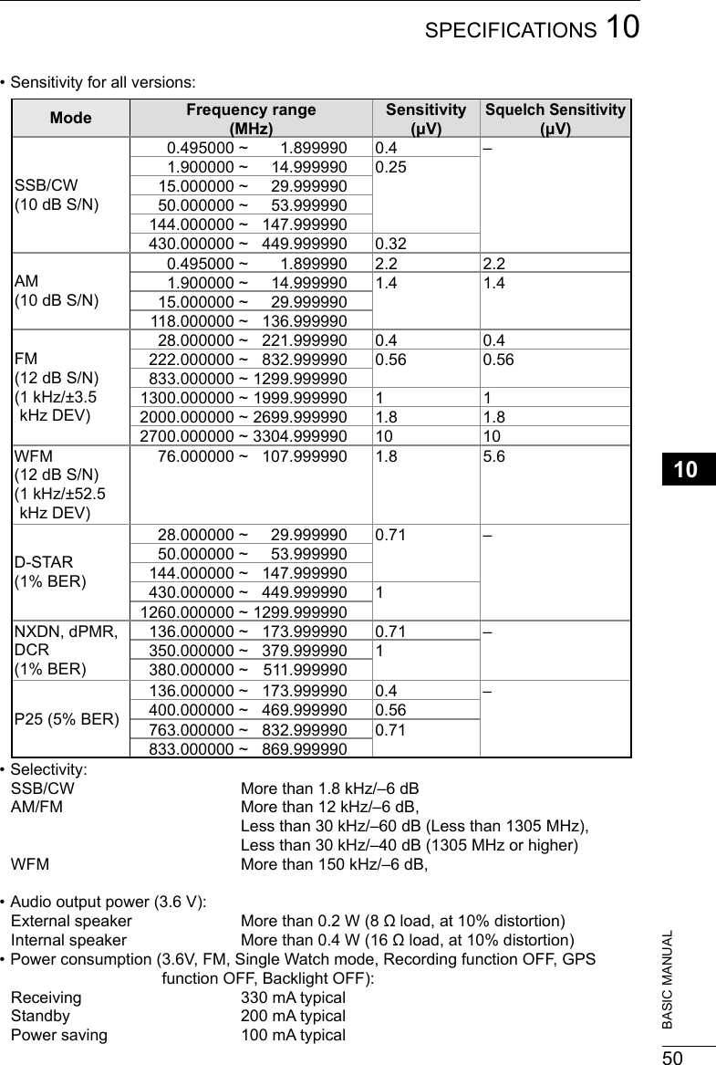
![20180249BASIC MANUAL10 SPECIFICATIONS DGeneral • Frequency coverage: [A band] USA-01 version 0.100000 ~ 821.999990 MHz 851.000000 ~ 866.999990 MHz 896.000000 ~ 3304.999990 MHz USA-02 version 0.100000 ~ 3304.999990 MHz EUR-01 version 0.100000 ~ 3304.999990 MHz [B band] USA-01 version 108.000000 ~ 520.000000 MHz USA-02 version 108.000000 ~ 520.000000 MHz EUR-01 version 108.000000 ~ 520.000000 MHz • Receive modes: Aband(≤1300MHz) FM/FM-N/WFM*1/AM/AM-N/LSB/USB/CW/CW-R/ D-STAR(DV)/P25/dPMR/NXDN-VN/NXDN-N/DCR A band (>1300MHz) FM/FM-N/WFM/AM/AM-N Bband FM/FM-N/AM/AM-N/D-STAR(DV)/P25/dPMR/NXDN-VN/NXDN-N/DCR • Operatingtemperaturerange: –20°C~+60°C,–4°F~+140°F • Frequencystability: Lessthan±2.5ppm(–20°C~+60°C,–4°F~+140°F) • Frequencyresolution: 0.01,0.1,1,3.125,5,6.25,8.33*2,9*3,10,12.5,15,20,25,30,50,100,125,200KHz • Numberofmemorychannels: 2000(in100groups) +400(Scanedges:100(50pairs), AutoMemoryWrite:200,andScanSkip:100) • NumberofGPSmemories: 300 • Powersupplyrequirement: 5.0VDC(±5%)(UsingthesuppliedUSBcable) 3.6VDC(Usingthesuppliedbatterypack) 4.5VDC(Usingthebatterycase) • Antennaimpedance: 50ΩUnbalanced • Dimensions(Projectionsnotincluded): 58(W)×143(H)×30.5(D)mm, 2.3(W)×5.6(H)×1.2(D)in • Weight(approximate): 200g,7.1oz (Theantennaandthebatterypacknotincluded) DReceiver • Receivesystem: TriplesuperheterodyneandDownconverter (AbandexceptWFM) Doublesuperheterodyne(BbandandWFM) • Intermediatefrequencies:Band 1st IF (MHz) 2nd (MHz) 3rd (MHz)A band 266.65,266.7,266.75 58.0500(exceptWFM)10.7000(WFM)0.4500(exceptWFM)B band 46.3500 0.4500 – LAllstatedspecicationsaretypicalandsubjecttochangewithoutnoticeorobligation.*2ForonlyAIRband*3ForonlyBCband*1“WFM”isnotselectable,dependingonthereceiverversionandreceivefrequency.](https://usermanual.wiki/ICOM-orporated/375410/User-Guide-3847850-Page-62.png)