ICOM orporated 375410 Scanning receiver User Manual
ICOM Incorporated Scanning receiver Users Manual
Users Manual

BASIC MANUAL
COMMUNICATIONS RECEIVER
iR30
This device complies with Part 15 of the FCC
rules. Operation is subject to the following two
conditions: (1) This device may not cause harmful
interference, and (2) this device must accept any
interference received, including interference that
may cause undesired operation.
WARNING: MODIFICATION OF THIS DEVICE
TO RECEIVE CELLULAR RADIOTELEPHONE
SERVICE SIGNALS IS PROHIBITED UNDER
FCC RULES AND FEDERAL LAW.

i
BASIC MANUAL
Thank you for choosing this Icom product.
This product is designed and built with
Icom’s state of the art technology and
craftsmanship. With proper care, this
product should provide you with years of
trouble-free operation.
■Important
READ ALL INSTRUCTIONS carefully
and completely before using the receiver.
SAVE THIS INSTRUCTION
MANUAL — This instruction manual
contains important operating instructions
for the IC-R30.
For advanced features and instructions,
see ADVANCED MANUAL on the Icom
website for details.
■Features
zDualwatch function that can
simultaneously receive and record two
different bands or modes*
* DV/DV, AM/AM, FM-N/FM-N, and DV/
FM-N mode dualwatch is not available.
zCovers 0.100 MHz to 3304.99999 MHz
for wide band reception
zReceives various digital modes such as
D-STAR, APCO P25 (Phase 1), NXDN,
dPMR, and DCR (Digital Convenience
Radio)
zA USB connector for data transmission
or battery charging
zBluetooth® function that can connect to a
Bluetooth® device such as the VS-3
zBuilt-in GPS receiver to check your
current location
zMeets IP57 requirements for dust-
protection and waterproof protection
(When the battery, antenna, jack cap,
and the slot cover are attached)
■Explicit denitions
WORD DEFINITION
RDANGER!
Personal death, serious
injury or an explosion may
occur.
RWARNING!
Personal injury, re hazard or
electric shock may occur.
CAUTION Equipment damage may
occur.
NOTE
If disregarded, inconvenience
only. No risk of personal
injury, re or electric shock.
Icom is not responsible for the
destruction, damage to, or performance
of any Icom or non-Icom equipment, if the
malfunction is because of:
• Force majeure, including, but not
limited to, res, earthquakes, storms,
oods, lightning, other natural disasters,
disturbances, riots, war, or radioactive
contamination.
• The use of Icom receivers with any
equipment that is not manufactured or
approved by Icom.
Icom, Icom Inc. and the Icom logo are
registered trademarks of Icom Incorporated
(Japan) in Japan, the United States, the
United Kingdom, Germany, France, Spain,
Russia, Australia, New Zealand, and/or other
countries.
NXDN is a trademark of Icom Incorporated
and JVC KENWOOD Corporation.
dPMR is a trademarks of the dPMR MoU
Association.
Adobe, Acrobat, and Reader are either
registered trademarks or trademarks of Adobe
Systems Incorporated in the United States
and/or other countries.
Microsoft and Windows are registered
trademarks of Microsoft Corporation in the
United States and/or other countries.
The Bluetooth word mark and logos are
registered trademarks owned by Bluetooth
SIG, Inc. and any use of such marks by Icom
inc. is under license.
Other trademarks and trade names are those
of their respective owners.

ii
1
7
4
10
15
18
2
8
13
5
11
16
3
9
14
6
12
17
BASIC MANUAL
■FCC Information
This equipment has been tested and found
to comply with the limits for a Class B digital
device, pursuant to part 15 of the FCC
Rules. These limits are designed to provide
reasonable protection against harmful
interference in a residential installation. This
equipment generates, uses and can radiate
radio frequency energy and, if not installed
and used in accordance with the instructions,
may cause harmful interference
to radio communications. However, there is no
guarantee that interference will not occur in a
particular installation.
If this equipment does cause harmful
interference to radio or television reception,
which can be determined by turning the
equipment off and on, the user is encouraged
to try to correct the interference by one or
more of the following measures:
• Reorient or relocate the receiving antenna.
• Increase the separation between the
equipment and receiver.
• Connect the equipment into an outlet on
a circuit different from that to which the
receiver is connected.
• Consult the dealer or an experienced radio/
TV technician for help.
CAUTION: Changes or modications
to this device, not expressly approved
by Icom Inc., could void your authority
to operate this device under FCC
regulations.
■IC-R30 and Bluetooth®
Interference
Bluetooth uses the 2.4 GHz band. When
using the IC-R30 in the 2.4 GHz band
near a Bluetooth device, interference
may occur. This may cause a decrease in
communication speed, and an unstable
connection.
In such case, use the IC-R30 away from
the Bluetooth device communication area,
or stop using the Bluetooth device.

iii
BASIC MANUAL
■Information FCC
Cet équipement a été testé et reconnu
conforme aux limites xées pour un appareil
numérique de classe B, conformément au
point 15 de la réglementation FCC. Ces
limites ont été xées an d’assurer une
protection raisonnable contre les interférences
nocives dans une installation résidentielle.
Cet équipement génère, utilise et peut
émettre un rayonnement de fréquence radio.
S’il n’a pas été installé conformément aux
instructions, il peut par ailleurs créer des
interférences perturbant les communications
radio. Toutefois, il n’y a aucune garantie que
les interférences ne se produiront pas dans
une installation particulière.
Si cet équipement crée des interférences
perturbant la réception de la radio ou de la
télévision, comme cela peut être déterminé
en éteignant et en allumant l’équipement,
l’utilisateur est invité à essayer de corriger
l’interférence en prenant une ou plusieurs des
mesures ci-après:
• Réorienter ou changer de place l’antenne de
réception.
• Éloi gner l’équipement et le récepteur.
• Connecter l’équipement sur une prise sur un
autre circuit que celui sur lequel le récepteur
est connecté.
• Faire appel au revendeur ou à un technicien
radio/TV expérimenté.
MISE EN GARDE: Tout changement ou
modication, non expressément approuvé
par Icom Inc., peut annuler l'autorisation
de l'utilisateur à utiliser cet appareil
conformément à la réglementation FCC.
■IC-R30 et interférences
Bluetooth
®
Bluetooth utilise la bande de 2,4 GHz. Si
vous utilisez l’IC-R30 dans la bande de 2,4
GHz à proximité d’un appareil Bluetooth,
ceci peut provoquer des interférences. Ceci
peut réduire le débit de communication et
rendre la connexion instable.
Dans ce cas, utilisez l’IC-R30 à distance
sufsante de la zone de communication
de l’appareil Bluetooth ou cessez d’utiliser
l’appareil Bluetooth.

iv
1
7
4
10
15
18
2
8
13
5
11
16
3
9
14
6
12
17
BASIC MANUAL
■Precautions
RDANGER! NEVER operate the receiver
near unshielded electrical blasting caps or in
an explosive atmosphere. This could cause an
explosion and death.
RWARNING! NEVER use or charge Icom
battery packs with non-Icom receivers or non-
Icom chargers. Only Icom battery packs are
tested and approved for use with Icom receivers
or charged with Icom chargers. Using third-party
or counterfeit battery packs or chargers may
cause smoke, re, or cause the battery to burst.
RWARNING! NEVER operate the equipment
with a headset or other audio accessories at
high volume levels. The continuous high volume
operation may cause a ringing in your ears. If you
experience the ringing, reduce the volume level
or discontinue use.
RWARNING! NEVER operate the receiver
while driving a vehicle. Safe driving requires your
full attention— anything less could result in an
accident.
CAUTION: DO NOT short the terminals of the
battery pack. Shorting may occur if the terminals
touch metal objects such as a key, so be careful
when placing the battery packs (or the receiver)
in bags, and so on. Carry them so that shorting
cannot occur with metal objects. Shorting may
damage not only the battery pack, but also the
receiver.
CAUTION: DO NOT connect the receiver directly
to a power source of more than the specied DC
voltage or use reverse polarity. Otherwise this will
damage the receiver.
CAUTION: DO NOT operate the receiver unless
the antenna, battery pack and covers are dry
before and after being securely attached. Conrm
that the antenna and battery pack are dry before
attaching. Exposing the inside to dust or water
can damage the receiver. After exposure to
water, clean the battery contacts thoroughly with
fresh water and dry them completely to remove
any water or salt residue.
CAUTION: DO NOT use harsh solvents such
as Benzine or alcohol when cleaning. This could
damage the equipment surfaces. If the surface
becomes dusty or dirty, wipe it clean with a soft,
dry cloth.
CAUTION: DO NOT place or leave the receiver
in direct sunlight or in areas with temperatures
below –20°C (–4˚F) or above +60°C (+140˚F).
BE CAREFUL! The receiver meets IP57*
requirements for dust-protection and waterproof
protection. However, once the receiver has
been dropped, waterproof protection cannot be
guaranteed because of possible damage to the
receiver’s case or the waterproof seal.
* Only when the BP-287 and antenna are
attached and [SP/USB] cover and [microSD]
slot cover are closed.
NOTE: Even when the receiver power is OFF, a
slight current still ows in the circuits. Remove
the battery pack or batteries from the receiver
when not using it for a long time. Otherwise, the
installed battery pack or batteries will become
exhausted, and will need to be recharged or
replaced.

v
BASIC MANUAL
DBattery cautions
Misuse of Li-ion batteries may result in the
following hazards: smoke, re, or the battery
may rupture. Misuse can also cause damage
to the battery or degradation of battery’s
performance.
RDANGER! NEVER strike or otherwise impact
the battery pack. Do not use the battery pack if it
has been severely impacted or dropped, or if the
pack has been subjected to heavy pressure. Battery
pack damage may not be visible on the outside of
the case. Even if the surface of the battery does not
show cracks or any other damage, the cells inside
the battery may rupture or catch re.
RDANGER! NEVER place or leave the battery
pack in areas with temperatures above 60˚C
(140˚F). High temperature buildup in the battery
cells, such as could occur near res or stoves,
inside a sun-heated vehicle, or in direct sunlight for
long periods of time may cause the battery cells to
rupture or catch re. Excessive temperatures may
also degrade pack’s performance or shorten the
battery cell’s life.
RDANGER! NEVER place or leave battery
packs near re. Fire or heat may cause them
to rupture or explode. Dispose of used battery
packs in accordance with local regulations.
RDANGER! NEVER solder the battery
terminals, or NEVER modify the battery pack.
This may cause heat generation, and the battery
may burst, emit smoke or catch re.
RDANGER! NEVER let uid from inside
the battery get in your eyes. This can cause
blindness. Rinse your eyes with clean water,
without rubbing them, and immediately get
medical treatment from an eye doctor. NEVER
disassemble the battery pack.
RWARNING! NEVER use the battery if it emits
an abnormal odor, heats up, or is discolored
or deformed. If any of these conditions occur,
contact your Icom dealer or distributor.
RWARNING! NEVER let uid from inside the
battery cells come in contact with your body. If it
does, immediately wash with clean water.
RWARNING! NEVER put the battery pack in
a microwave oven, high-pressure container, or
in an induction heating cooker. This could cause
a re, overheating, or cause the battery cells to
rupture.
RCAUTION: DO NOT expose the battery pack
to rain, snow, saltwater, or any other liquids. Do not
charge or use a wet pack. If the pack gets wet, be
sure to wipe it dry before using.
CAUTION: DO NOT use the battery pack outside
the specied temperature range, –20˚C ~ +60˚C
(–4˚F ~ +140˚F). Otherwise this will reduce the
pack’s performance and battery cell life.
DO NOT leave the pack fully charged, completely
discharged, or in an excessive temperature
environment (above 50˚C, 122˚F) for an
extended period of time. Otherwise a shorter
battery pack life could occur. If the battery pack
must be left unused for a long time, it must be
detached from the receiver after discharging. You
may use the pack until the remaining capacity is
about half, then keep it safely in a cool dry place
in the following temperature range:
–20˚C (–4˚F) ~ +50˚C (+122˚F) (for a month)
–20˚C (–4˚F) ~ +40˚C (+104˚F)
(for three months)
–20˚C (–4˚F) ~ +20˚C (+68˚F) (for a year).
NOTE: Replace the battery pack with a new one
approximately ve years after manufacturing,
even if it still holds a charge. The material inside
the battery material will become weak after a
period of time, even with little use. The estimated
number of times you can charge the pack is
between 300 and 500. Even when the battery
appears to be fully charged, the operating time of
the receiver may become short when:
• Approximately ve years have passed since the
battery was manufactured.
• The pack has been repeatedly charged.
■Battery and charging cautions

vi
1
7
4
10
15
18
2
8
13
5
11
16
3
9
14
6
12
17
BASIC MANUAL
DCharging cautions
RDANGER! NEVER charge the battery pack in
areas with extremely high temperatures, such as
near res or stoves, inside a sun-heated vehicle,
or in direct sunlight. Otherwise the safety/
protection circuit in the battery will activate,
causing the battery cells to stop charging.
RDANGER! NEVER charge the receiver during
a lightning storm. It may result in an electric
shock, cause a re or damage the receiver.
Always disconnect the power adapter before a
storm.
RWARNING! DO NOT charge or leave
the battery in the battery charger beyond the
specied time for charging. If the pack is not
completely charged by the specied time, stop
charging and remove the battery from the
battery charger. Continuing to charge the battery
beyond the specied time limit may cause a re,
overheating, or the battery may rupture.
RCAUTION: DO NOT insert the receiver with
the battery pack attached into the charger if they
are wet or soiled. This could corrode the battery
charger terminals or damage the charger. The
charger is not waterproof.
CAUTION: DO NOT charge the battery pack
outside of the specied temperature range:
15˚C ~ 40˚C (59˚F ~ 104˚F). Icom recommends
charging the pack at 25˚C (77˚F). The pack
may heat up or rupture if charged out of the
specied temperature range. Additionally, battery
performance or battery life may be reduced.

vii
BASIC MANUAL
■Recommendation
CLEAN THE RECEIVER THOROUGHLY
IN A BOWL OF FRESH WATER after
exposure to saltwater, and dry it before
operating. Otherwise, the receiver’s keys,
switches, and controllers may become
unusable, due to salt crystallization, and/or
the charging terminals of the battery pack
may corrode.
NOTE: If the receiver’s waterproof
protection appears defective, carefully
clean it with a soft, damp (fresh water)
cloth, then dry it before operating.
The receiver may lose its waterproof
protection if the case, jack cap, or
connector cover is cracked or broken, or
the receiver has been dropped.
Contact your Icom distributor or your
dealer for advice.
■Operating theory
Electromagnetic radiation, which has
frequencies of 20,000 Hz (20 kHz*) and
above, is called radio frequency (RF)
energy because, it is useful in radio
transmissions. The IC-R30 receives RF
energy from 0.100 MHz* to 3304.99999
MHz and converts it into audio frequency
(AF) energy which in turn actuates a
loudspeaker to create sound waves.
AF energy is in the range of 20 to 20,000 Hz.
* kHz is an abbreviation of kilohertz or 1000
hertz, MHz is abbreviation of megahertz
or 1,000,000 hertz, where hertz is a unit
of frequency.
■Operating notes
The IC-R30 may receive its own oscillated
frequency, resulting in no reception or only
noise reception, on some frequencies.
The IC-R30 may receive interference
from extremely strong signals on different
frequencies or when using an external
high-gain antenna.

viii
1
7
4
10
15
18
2
8
13
5
11
16
3
9
14
6
12
17
BASIC MANUAL
■About CE and DOC
Hereby, Icom Inc. declares
that the versions of IC-R30
which have the “CE” symbol
on the product, comply with
the essential requirements of the Radio
Equipment Directive, 2014/53/EU, and the
restriction of the use of certain hazardous
substances in electrical and electronic
equipment Directive, 2011/65/EU. The full
text of the EU declaration of conformity is
available at the following internet address:
http://www.icom.co.jp/world/support
■ Disposal
The crossed-out wheeled-bin
symbol on your product,
literature, or packaging
reminds you that in the
European Union, all electrical
and electronic products,
batteries, and accumulators
(rechargeable batteries) must be taken to
designated collection locations at the end
of their working life. Do not dispose of
these products as unsorted municipal
waste. Dispose of them according to the
laws in your area.
■Voice coding technology
The AMBE+2™ voice coding Technology
embodied in this product is protected
by intellectual property rights including
patent rights, copyrights and trade secrets
of Digital Voice Systems, Inc. This voice
coding Technology is licensed solely for
use within this Communications Equipment.
The user of this Technology is explicitly
prohibited from attempting to extract,
remove, decompile, reverse engineer, or
disassemble the Object Code, or in any
other way convert the Object Code into a
human-readable form. U.S. Patent Nos.
#8,595,002, #8,359,197, #8,315,860,
#8,200,497, #7,970,606 and #6,912,495.
ix
BASIC MANUAL
■Important notes
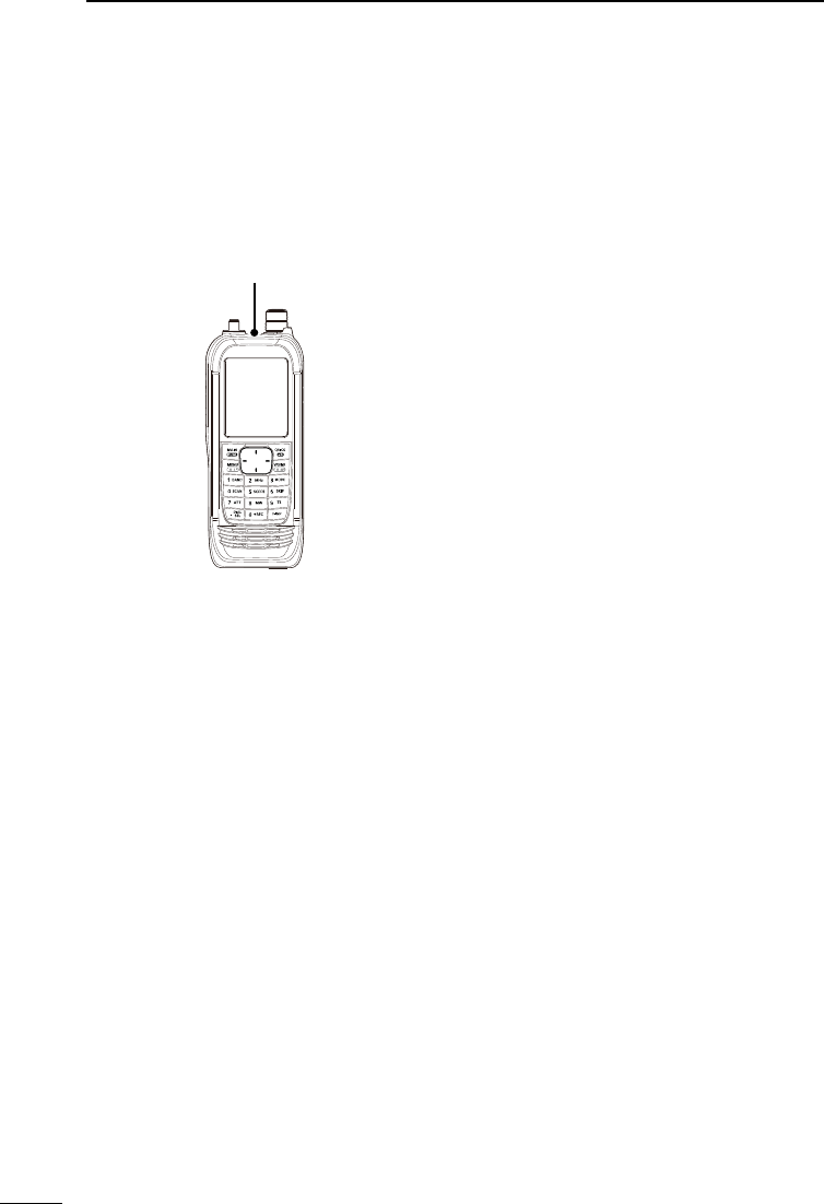
DWhen using the GPS receiver
• The GPS receiver is installed under the receiver’s top panel. Therefore, when the GPS
receiver is activated, do not cover the top with anything that will block the satellite
signals.
The GPS receiver is installed here.
• GPS signals cannot pass through metal objects. When using the receiver inside a
vehicle, you may not receive GPS signals. We recommend you use it near a window.
• The GPS receiver may not work if used in the following locations:
1. Tunnels or high-rise buildings
2. Underground parking lots
3. Under a bridge or viaduct
4. In remote forested areas
5. Under bad weather conditions (rainy or cloudy day)
• The Global Positioning System (GPS) is built and operated by the U.S. Department of
Defense. The Department is responsible for accuracy and maintenance of the system.
Any changes by the Department may affect the accuracy and function of the GPS
system.
DSpurious signals
You may hear some noises caused by spurious signals generated in the receiver’s circuit
but they do not indicate a receiver malfunction.
DNoise signals while charging
You may hear some noises caused by signals generated in the charging circuit. Be sure
to turn OFF the receiver before charging.
x
1
7
4
10
15
18
2
8
13
5
11
16
3
9
14
6
12
17
BASIC MANUAL
■About the IC-R30 manuals
The following manuals are supplied for your IC-R30.
DBasic manual (This manual)
Instructions for the basic operations, precautions.
DAdvanced manual (PDF on the Icom website)
Instructions for the advanced operations, as shown below.
• Battery operation*
• Using a microSD card*
• Recording the received audio*
• Memory operation*
• GPS operation*
• Menu screen*
• Other functions*
• Bluetooth® operation*
• Firmware updating
• Options*
• Specications
LThis manual can be downloaded from the Icom website.
*Only the basic instructions are described in this manual.
TIP:
You can download each manual from the Icom website:
http://www.icom.co.jp/world/support
To read the manual, Adobe® Acrobat® Reader® is required. If you have not installed it,
download and install Adobe® Acrobat® Reader® from Adobe Systems Incorporated’s
website.
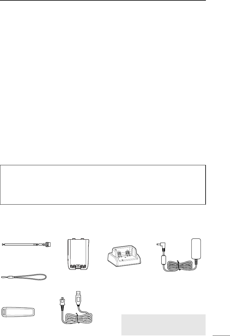
■Supplied Accessories
Rapid charger
Antenna
Hand strap
Belt clip
Battery pack Power adapter
NOTE: Some accessories are not
supplied, or the shape is different,
depending on the receiver version.
USB cable
(A-microB type)

xi
BASIC MANUAL
TABLE OF CONTENTS
■Important ........................................... i
■Features ............................................ i
■Explicit denitions ............................. i
■FCC Information ............................... ii
■IC-R30 and Bluetooth® Interference . ii
■Information FCC ...............................iii
■IC-R30 et interférences Bluetooth® ....iii
■Precautions ..................................... iv
■Battery and charging cautions ......... v
DBattery cautions........................... v
DCharging cautions ...................... vi
■Recommendation ............................vii
■Operating theory .............................vii
■Operating notes ..............................vii
■Voice coding technology ................viii
■About CE and DOC ........................viii
■Disposal .........................................viii
■Important notes ............................... ix
DWhen using the GPS receiver .... ix
DSpurious signals ......................... ix
DNoise signals while charging ...... ix
■About the IC-R30 manuals ............... x
DBasic manual (This manual) ........ x
DAdvanced manual
(PDF on the Icom website) ............. x
■Supplied Accessories ....................... x
1 PREPARATION ........................ 1
■Attaching the supplied accessories ..1
DBattery pack ................................1
DAntenna ....................................... 1
DHand strap ...................................1
DBelt clip ........................................1
■Charging the battery pack ................2
■Charging time and the capacity
of the battery pack ............................2
■Charging with a USB cable .............. 3
■Inserting a microSD card .................4
■Turning ON the receiver ...................4
■Adjusting an audio level ................... 4
■Saving a setting data onto
a microSD card.................................5
DFormatting the microSD card ......5
DSaving a setting data ...................6
2 PANEL DESCRIPTION ............7
■Front, top, and side panels ..............7
■Keypad ............................................. 8
■Function display ............................... 9
3 BASIC OPERATION ..............11
■MENU screen ................................. 11
DMENU screen operation ............ 11
DSelecting a Menu item ...............12
■Quick Menu window ....................... 13
■ Setting the squelch level ................ 14
■Monitor function .............................14
■Speech function .............................14
■Setting the frequency ..................... 15
DDirectly entering a frequency.....15
DChanging the frequency
in MHz steps..............................15
DSelecting the tuning step ........... 16
■Selecting the Frequency
Selecting mode...............................16
DVariable Frequency Oscillator
(VFO) mode ...............................16
DMemory mode ...........................16
■Selecting the receive mode ............17
■Selecting the receive band .............17
■DIAL/VOL Switch function ..............18
■Setting the RF gain ........................18
■Attenuator ......................................18
■Dualwatch function .........................19
DTurning Dualwatch function
ON or OFF .................................19
DSelecting the MAIN band...........20
DSetting the volume
for Dualwatch ............................20
■Key Lock function ...........................20
■Band Scope function ......................21
DSweep operation .......................22
4 RECORDING
AND PLAYING BACK ............23
■About the microSD card ................. 23
■Setting the Record operation .........24
■Recording .......................................24
DStarting recording ...................... 24
DStopping recording ....................24
■Playing back ...................................25
■Removing the MicroSD card .......... 26
DRemoving when the receiver
is OFF ........................................26
DRemoving when the receiver
is ON .........................................26

xii
1
7
4
10
15
18
2
8
13
5
11
16
3
9
14
6
12
17
BASIC MANUAL
TABLE OF CONTENTS
5 MEMORY CHANNELS ..........27
■Selecting a memory channel ..........27
■Viewing the memory channel
contents ..........................................27
■Writing a new memory channel ......28
DWriting to a blank channel ......... 28
DWriting to a specied channel
in a specied group ...................28
6 SCANNING ............................29
■Scan type .......................................29
DVFO scan ..................................29
DMemory scan .............................29
DTone scan .................................. 29
■About Scans ...................................30
■Starting or canceling the scan ........31
■Convenient function for a Scan ......31
■VFO scan .......................................32
DFull scan (ALL) ..........................32
DBand scan (BAND) .................... 32
DProgram scan (P00 ~ P49) ........32
DProgram Link scan
(P-LINK 0–9) .............................32
DAuto memory write scan
(Auto MW) .................................32
DEntering Program Scan ranges . 33
DAbout the Program Link Scan ...34
DSetting the Program Link
function ......................................34
DStoring Skip frequencies ...........35
DProgram Skip Scan function ......35
DTemporary Skip function ............35
■Memory scan .................................36
DAll scan (ALL) ............................ 36
DMode scan (MODE)...................36
DNear Station scan
(Near Station) ............................ 36
DGroup Link scan
(GROUP LINK) .......................... 36
DGroup scan (GROUP 00 ~ 99) ..36
DSetting the Group Link...............37
DSetting the skip channel ............37
■About the Priority Watch function ...38
■Starting or canceling the Priority
Watch function ................................39
DStarting the Priority Watch .........39
DCanceling the Priority Watch ..... 39
DThe Priority Watch and
Scanning ...................................39
7 GPS Operation ......................40
DChecking the GPS signal ..........40
■Checking your GPS location .......... 41
DDisplaying Position Data ...........41
DAbout the GPS POSITION
screen........................................41
■GPS Logger function ......................42
DAbout the log le........................42
DTurning OFF the GPS Logger
function ......................................42
8 OTHER FUNCTIONS .............43
■Operating Bluetooth® .....................43
DElectromagnetic Interference ....43
DPairing with a device .................43
DDisconnecting a paired device ..44
DUnpairing a device.....................45
■Using the Noise Blanker (NB) ....... 45
■Using the Automatic Noise Limiter
(ANL) .............................................. 45
■Using the Automatic Frequency
Control (AFC) .................................45
■Using the Voice Squelch Control
(VSC) ..............................................45
■Using a Weather channel
(For only the USA version) .............46
DSelecting a Weather channel ....46
DReceiving a Weather Alert .........46
9 RESET/
TROUBLESHOOTING ...........47
■Resetting ........................................ 47
DPartial reset ...............................47
■Troubleshooting .............................48
201802
1
BASIC MANUAL
1PREPARATION
■Attaching the supplied accessories
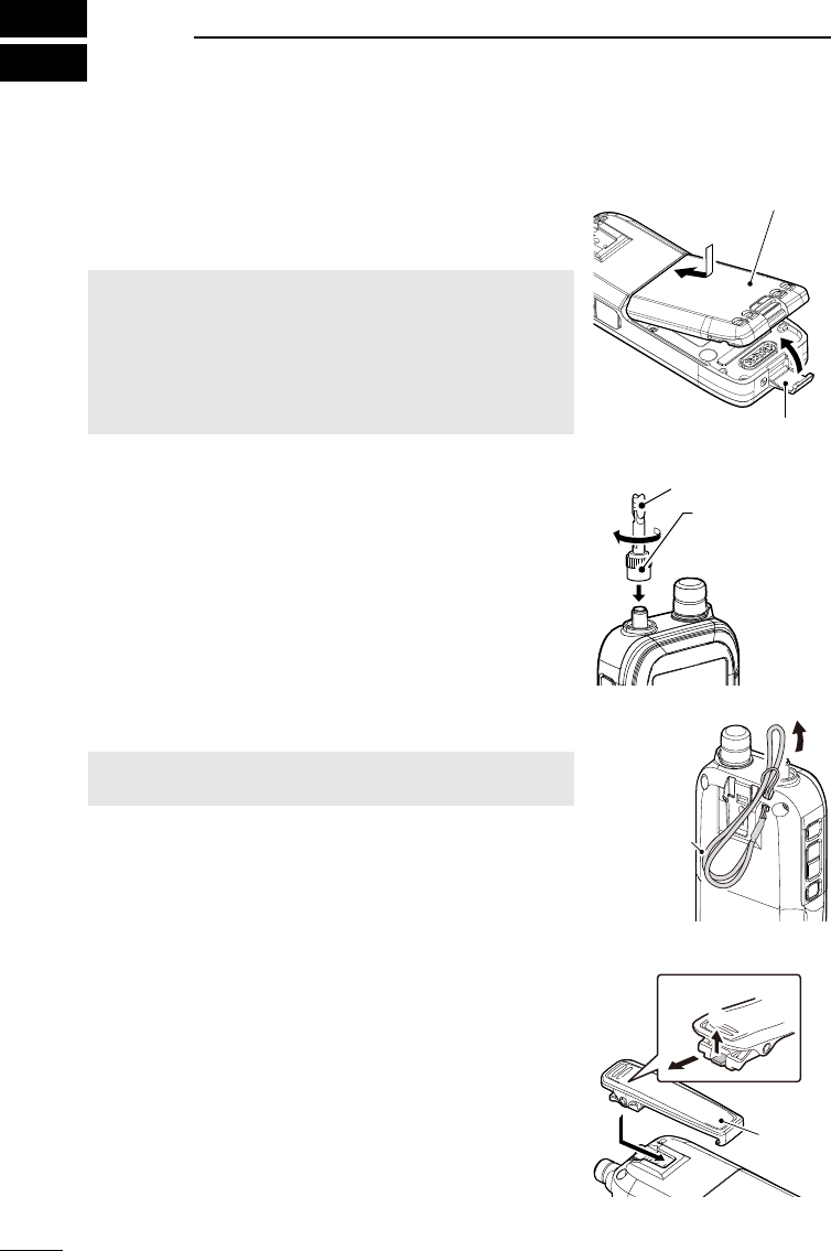
DBattery pack
Attach (q → w) or detach the battery pack or battery case.
L Turn OFF the receiver before attaching or detaching the
battery pack.
NOTE:
• BE CAREFUL! Do not break your nger nail.
• Even when the receiver is OFF, a small current still
ows in the receiver. Remove the battery pack or case
from the receiver when not using it for a long time.
Otherwise, the batteries in the pack or the case will
become exhausted.
1
2
Battery pack
(Supplied)
Latch
DAntenna
Connect the supplied antenna to the connector.
This receiver has an SMA type antenna connector.
Antenna (Supplied)
Hold here to
tighten the
antenna screw.
DHand strap
RWARNING! NEVER swing the receiver by holding the
hand strap. This can cause injury to yourself or others.
Hand strap
(Supplied)
DBelt clip
To attach the belt clip, slide the belt clip in the direction of
the arrow until the belt clip locks in place, and makes a
‘click’ sound.
To detach the belt clip, lift the tab up (1), and slide the
belt clip in the direction of the arrow (2).
q
w
To detach
Belt clip
2
1
PREPARATION 1
201802 201802
BASIC MANUAL
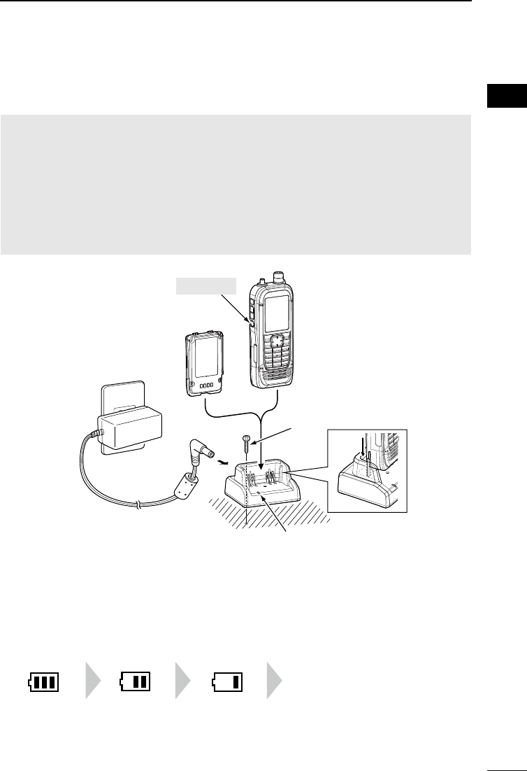
■Charging the battery pack
Prior to using the receiver for the rst time, the battery pack must be fully charged for
optimum life and operation.
NOTE:
• BE SURE to turn OFF the receiver before charging the battery pack. Otherwise the
attached battery pack cannot be charged completely, or it will take much longer to charge.
• The battery pack becomes hot while charging.
• After the charging is completed, the battery life will be approximately 8.3 hours when the
Dualwatch function is ON (A band: continuously receiving, B band: standing by), the Power
Save function is set to “Auto (Short),” the internal speaker’s volume is set to “20,” the GPS
function is ON, and the Bluetooth function is OFF.
• Depending on your receiving environment, the receiver may be effected by the switching
noise generated from the power adapter. Keep the receiver away from the power adapter.
■Charging time and the capacity of the battery pack
Charging time*: Approximately 4 hours when using the BC-223
* Depending on your receiving situation.
Blink
容量表示
充電表示
Blink
容量表示
充電表示
Blink
容量表示
充電表示
Blinking
The battery
has sufcient
capacity.
The battery is
exhausted a
little.
The battery
is nearing
exhaustion.
The battery
is almost fully
exhausted.
Turn OFF
Receiver +
Battery pack
Self tapping screw M4×35
(User supplied)
Battery pack*
Charge indicator
• Lights orange while
charging.
• Lights green when charging
is completed.
To an AC outlet
Power adapter*
Battery charger*
* May not be supplied, or the shape may be
different, depending on the receiver version.
3
1PREPARATION
201802
BASIC MANUAL
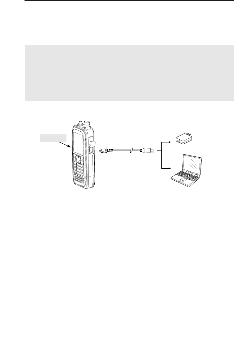
■Charging with a USB cable
You can charge the battery pack with the supplied USB cable (A-microB type).
NOTE:
• BE SURE to turn OFF the receiver before charging the battery pack. Otherwise the
attached battery pack cannot be charged completely, or it will take much longer to charge.
• If you use a third party USB cable, you may not be able to charge:
- Depending on your USB cable or power adapter.
- When using a USB hub or connecting to a low output USB port.
• Charging time is approximately 5 hours when using the supplied USB cable and 1 A output
USB port, and the temperature is 25°C (77°F).
Charging time may differ, depending on the USB port.
USB cable
(A-microB type)
To a USB port PC
Power adapter
or external battery
(User supplied)
Turn OFF
4
1
PREPARATION 1
201802 201802
BASIC MANUAL
■Inserting a microSD card
Refer to page 23 for the usable microSD card.
1. Turn OFF the receiver.
2. Pull down the [microSD] slot cover on the side panel.
3. With the terminals facing the front, insert the card into the slot until it locks in place
and makes a ‘click’ sound.
LWhen removing, push in the microSD card until a ‘click’ sounds. The card is unlocked,
and you can pull it out.
CAUTION:
• DO NOT touch the card terminals.
• DO NOT remove the card from the receiver while the card is being accessed.
Otherwise, the card data may be corrupted or deleted.
4. Completely close the [microSD] slot cover.
[microSD] slot
microSD card
Terminals
facing the front
Slot cover
CAUTION: DO NOT
forcibly or inversely insert
the card. It will damage
the card or the slot.
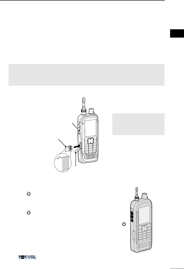
■Turning ON the receiver
■Adjusting an audio level
zHold down [ ] for 1 second to turn ON the receiver.
• After the opening message and the remaining battery
capacity are displayed, the receiving frequency is
displayed.
zHold down [ ] for 1 second again to turn OFF the
receiver.
zPush [▲] or [▼] to adjust an audio level.
LThe display shows the volume level while adjusting.
LContinuously holding down [▲] or [▼] quickly adjusts the
level.
LWhen “ ” is displayed, the functions assigned to
[DIAL] and [▲]/[▼] are swapped.
In this case, rotate [DIAL] to adjust the level.
[ ]
[▲]
[▼]
5
1PREPARATION
201802
BASIC MANUAL
■ Saving a setting data onto a microSD card
You can save the Memory channels, Menu screen item settings, and GPS memories on a
microSD card. Saving settings on a card enables you to easily restore the receiver to its
previous settings, even if you perform an All Reset.
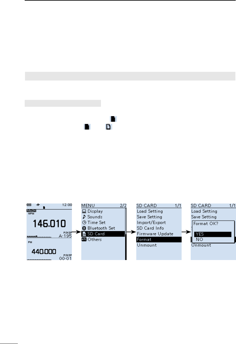
DFormatting the microSD card
IMPORTANT! Before using a microSD card, format the card using the receiver.
L Formatting a card deletes all its data. Before formatting any used card, back up its data onto
your PC.
[MENU] > SD Card > Format
1. Turn ON the receiver.
LIf a microSD card is inserted, “ ” is displayed.
LWhen accessing, “ ” and “ ” alternately blink.
2. Push [MENU].
3. Select “Format” in the “SD Card” menu.
(Rotate [DIAL] to select it, and then push [ENTER].)
• A conrmation dialog is displayed.
4. Select “YES,” and then push [ENTER].
• The formatting starts and the display shows the formatting progress.
• After the formatting ends, returns to the MENU screen.
L If “The GPS Logger function is activated.” is displayed, turn OFF the function (p. 42) or
ignore the message and select “YES.”
5. Push [CLEAR] to return to the Main screen.
6
1
PREPARATION 1
201802 201802
BASIC MANUAL
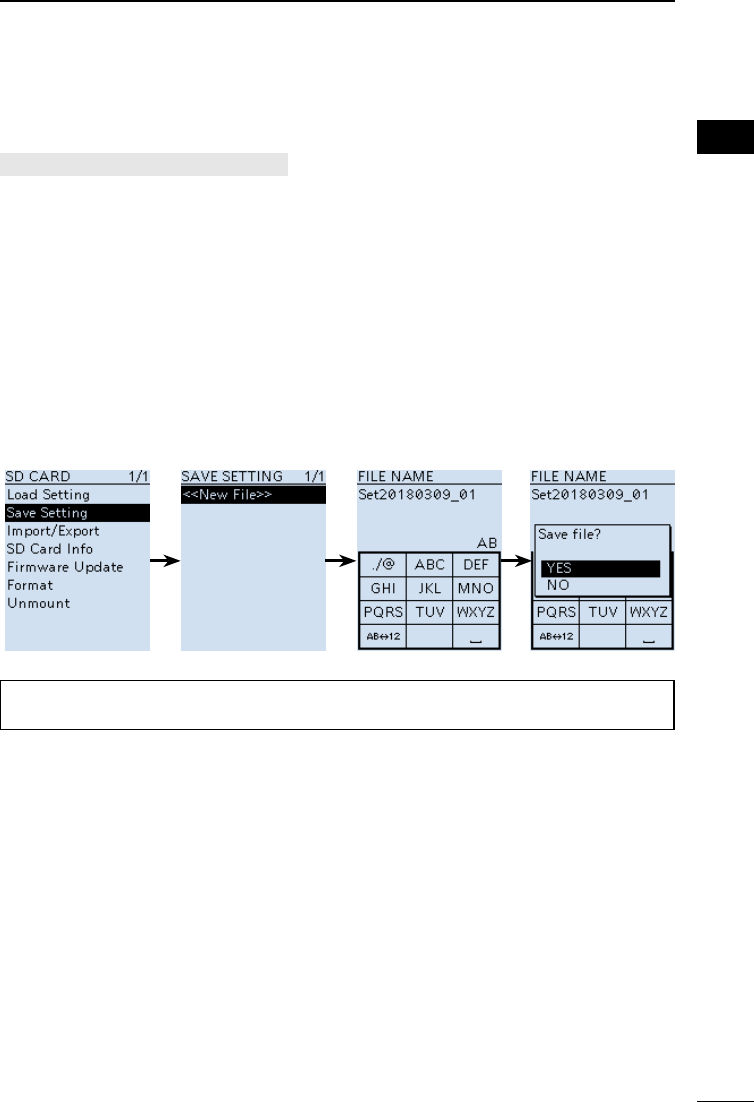
DSaving a setting data
[MENU] > SD Card > Save Setting
1. Push [MENU].
2. Select “Save setting” in the “SD Card” menu.
(Rotate [DIAL] to select it, and then push [ENTER].)
3. Select “<<New File>>,” and then push [ENTER].
LThe le name is automatically named in the following manner: Setyyyymmdd_xx
(yyyy: Year, mm: month, dd: day, xx: serial number).
4. Push [ENTER] to set the file name.
• A conrmation dialog is displayed.
5. Select “YES,” and then push [ENTER].
• While saving, a progress bar is displayed, then returns to the SD CARD screen after the
saving is completed.
6. Push [CLEAR] to return to the Main screen.
TIP: You can edit the saved settings on your PC using the optional CS-R30 cloning
software.
201802
7
BASIC MANUAL
2PANEL DESCRIPTION
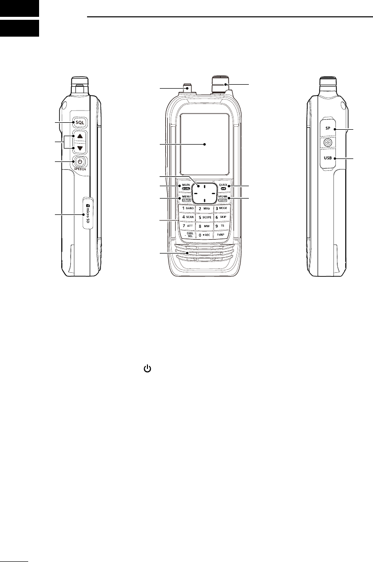
■Front, top, and side panels
1SQUELCH ADJUSTMENT KEY [SQL]
zWhile pushing, rotate [DIAL] to adjust the squelch level. (p. 14)
zPush or hold down to turn the Monitor function ON or OFF. (p. 14)
2VOLUME ADJUSTMENT KEYS [▲][▼]
Push to adjust the audio volume level.
3POWER/SPEECH KEY [ ]/[SPEECH]
zPush to turn the Speech function ON or OFF. (p. 14)
zHold down for 1 second to turn the receiver ON or OFF.
4microSD CARD SLOT
Accepts a microSD card (User supplied). (p. 23)
5ANTENNA CONNECTOR
Connect the supplied antenna.
6DIRECTIONAL PAD D-Pad (Up)/D-Pad (Down)/D-Pad (Left)/D-Pad (Right)
Push to select a menu item, setting, and so on. (p. 49)
7MAIN/DUAL KEY [MAIN]/[DUAL]
zPush to set the A or B band as the main band. (p. 19)
zHold down for 1 second to turn the Dualwatch function ON or OFF. (p. 19)
8MENU/ENTER KEY [MENU]/[ENTER]
zPush to enter the Menu screen.
zPush to set the entered data or selected item.
1
2
3
4
5
6
7
8
9
*
*
Function
display (p. 9)
Keypad
(p. 8)
Speaker
*Close the cover rmly when no in use.

8
2
PANEL DESCRIPTION 2
201802 201802
BASIC MANUAL
9TUNING DIAL [DIAL]
Rotate to set the frequency, select a Memory channel, a menu item, or enter
characters. (pp. 15, 27 and 49)
QUICK/LOCK KEY [QUICK]/[ ]
zPush to enter or exit the Quick Menu screen. (p. 13)
zHold down for 1 second to activate the Key Lock function. (p. 20)
VFO/MEMORY/CLEAR KEY [VFO]/[MR]/[CLEAR]
zPush to select the VFO mode or Memory mode. (p. 16)
zPush to cancel the entered data, selected item, exit the current mode, or return to
the previous screen.
SPEAKER JACK
Connects to a 3.5 mm (1/8 inch) external speaker plug.
USB (Micro-B) CONNECTOR
Connects to a PC using the supplied USB cable. (p. 3)
■Keypad
zPush to set the frequency in the VFO mode. (p. 16)
zPush or hold down to use the functions listed below.
KEYS PUSH HOLD DOWN
[1]/[BAND] Selects a band in the VFO mode,
or selects a group in the Memory
mode.
[2]/[MHz] Turns the MHz tuning mode ON or
OFF (VFO Mode).
[3]/[MODE] Displays the Receive mode
options.
[4]/[SCAN] Displays the Scan type options. Starts the last selected scan.
[5]/[SCOPE] Displays the Sweep type options.
[6]/[SKIP] Displays the Skip/Program Skip
options (in the Memory mode).
[7]/[ATT] Displays the Attenuator options.
[8]/[MW] Displays the Memory Write
options.
Writes memory to the selected
channel.
[9]/[TS] Displays the Tuning step options.
[.]/[DIAL SEL] Changes the functions assigned to
[DIAL] and [▲]/[▼].
[0]/[●REC] Starts or stops the voice recording.
[F-INP] Displays the Frequency Setting
screen.
9
2PANEL DESCRIPTION
201802
BASIC MANUAL
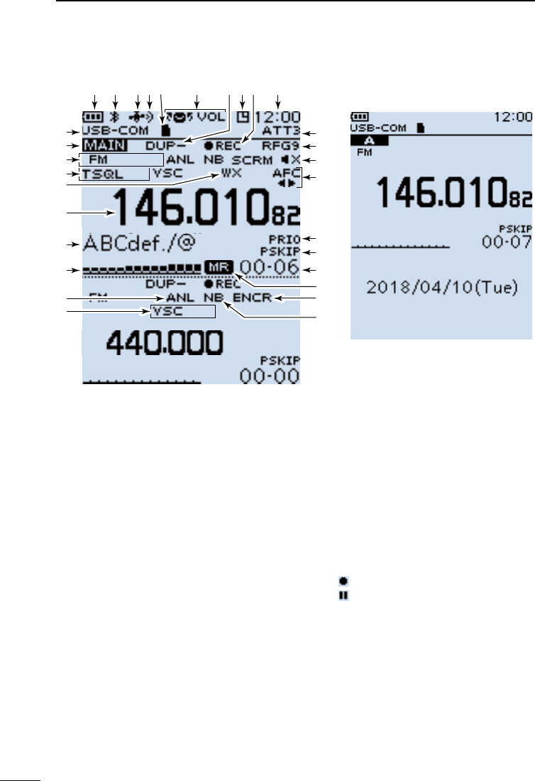
1BATTERY INDICATOR
Displays the battery status. (p. 2)
2Bluetooth® ICON
Displayed when a Bluetooth device is
connected. (p. 43)
3GPS ICON
Displays satellite acquisition status.
(p. 40)
4GPS ALARM ICON
Blinks when the GPS Alarm sounds.
See ADVANCED MANUAL for details.
5microSD CARD ICON (p. 23)
zDisplayed when a microSD card is
inserted.
zBlinks while the receiver is accessing
a microSD card.
6VOLUME/DIAL SWITCH ICON
Displayed when the Volume Adjustment
function is assigned to [DIAL].
L “SQL” is displayed while adjusting the
squelch.
7DUPLEX INDICATOR
z “DUP+”: Displayed when Plus
duplex is selected.
z“DUP– ”: Displayed when Minus
duplex is selected.
8AUTO POWER OFF ICON
Displayed when the Auto Power OFF
function is ON.
9RECORD ICON (p. 24)
z“”: Displayed when recording
z“”: Displayed when recording is
paused.
CLOCK READOUT
Displays the current time.
ATTENUATOR INDICATOR
Displayed when attenuator “ATT1” ~
“ATT3” is ON.
RF GAIN INDICATOR
Displayed when the RF gain is set to
other than “RFG MAX” to indicate that
the RF gain is reduced.
■Function display
123456 78
9
Dual band display (Dualwatch function is ON)
Single band display
(Dualwatch function is OFF)
(These screens are only examples.)

10
2
PANEL DESCRIPTION 2
201802 201802
BASIC MANUAL
MUTE ICON
Displayed when the sub band audio
signal is muted, depending on the
receive band or mode. (p. 19)
AFC ICON
Displayed when the Automatic
Frequency Control function is ON.
(p. 45)
PRIORITY ICON
Displayed during a Priority watch.
(p. 38)
SKIP INDICATOR (p. 37)
z“SKIP”: Displayed when Memory
Skip is set.
z“PSKIP”: Displayed when Program
Skip is set.
MEMORY CHANNEL READOUT
Displays the selected memory channel
number.
MEMORY MODE ICON
Displayed when the Memory mode is
selected. (p. 16)
SCRAMBLER/ENCRYPTION
INDICATOR
z“SCRM”:
Displayed when the
Descrambler function is ON.
z“ENCR”:
The Decryption function is ON.
NOISE BLANKER ICON
Displayed when the Noise Blanker
function is ON. (p. 45)
VSC INDICATOR
Displayed when the Voice Squelch
Control function is ON. (p. 45)
AUTOMATIC NOISE LIMITER ICON
Displayed when the Automatic Noise
Limiter function is ON. (p. 45)
S-METER
Displays the relative signal strength of
the receive signal.
MEMORY NAME READOUT
Displays the memory name, if entered.
FREQUENCY READOUT
Displays a variety of information, such
as the frequency or menu contents.
WX INDICATOR
(For only the USA version.)
Displayed when the Weather Alert
function is ON.
TONE/DIGITAL SQUELCH INDICATOR
Displayed when a Tone/Digital squelch
function is ON.
zTSQL: Tone Squelch.
zDTCS: DTCS Squelch.
zTSQL-R: Reverse Tone Squelch.
zDTCS-R: Reverse DTCS Squelch.
zCSQL: Digital Code Squelch.
(D-STAR)
zNAC: Network Access Code
(P25)
zCOM ID: Common ID (dPMR)
zCC: CC (dPMR)
zRAN: Radio Access Number
(NXDN-VN/NXDN-N)
zUC: User Code (DCR)
MODE INDICATOR
Displays the selected receive mode.
MAIN BAND ICON
z When the Dualwatch function is ON,
indicates that the selected band (A or
B) is the Main band.
z When the Dualwatch function is OFF,
indicates the selected band (A or B).
USB CONNECTION INDICATOR
Displayed when a PC is connected
through a USB cable, and “Serialport” is
selected in the Menu screen.
( [MENU] > Function > USB Connect >
Serialport)
201802
11
BASIC MANUAL
3BASIC OPERATION
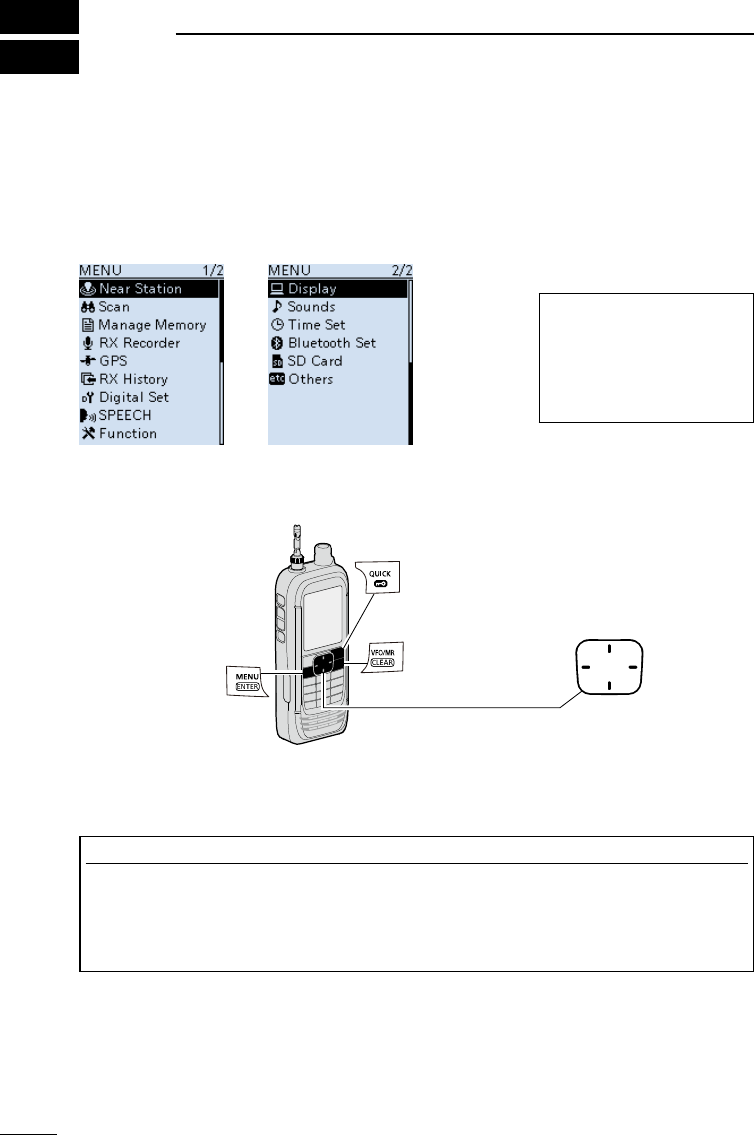
■MENU screen
The MENU screen is displayed after pushing [MENU].
You can use the MENU screen to change settings.
See the appendix for the MENU item list. (p. 49)
For details of each item, see ADVANCED MANUAL.
MENU screen structure
DMENU screen operation
TIP: The MENU screen
is constructed in a tree
structure. You may go to
the next tree level, or go
back a level, depending on
the selected item.
D-pad (Up)
Selects an item
or option.
D-pad (Right)
Goes to the
next tree level.
D-pad (Left)
Goes to the previous
tree level.
Closes the
MENU screen.
Opens the Quick Menu window.
• Opens the MENU screen
• Sets an option.
Simplied description—‘Select’ operation
In this manual, user’s ‘Select’ operation is simplied, as described below.
Simplied description: Select “Function,” and then push [ENTER].
Operation: Push D-pad (Up) or (Down) to select “Function,” and then
push [ENTER].
D-pad (Down)
Selects an item
or option.
12
3
BASIC OPERATION 3
201802 201802
BASIC MANUAL
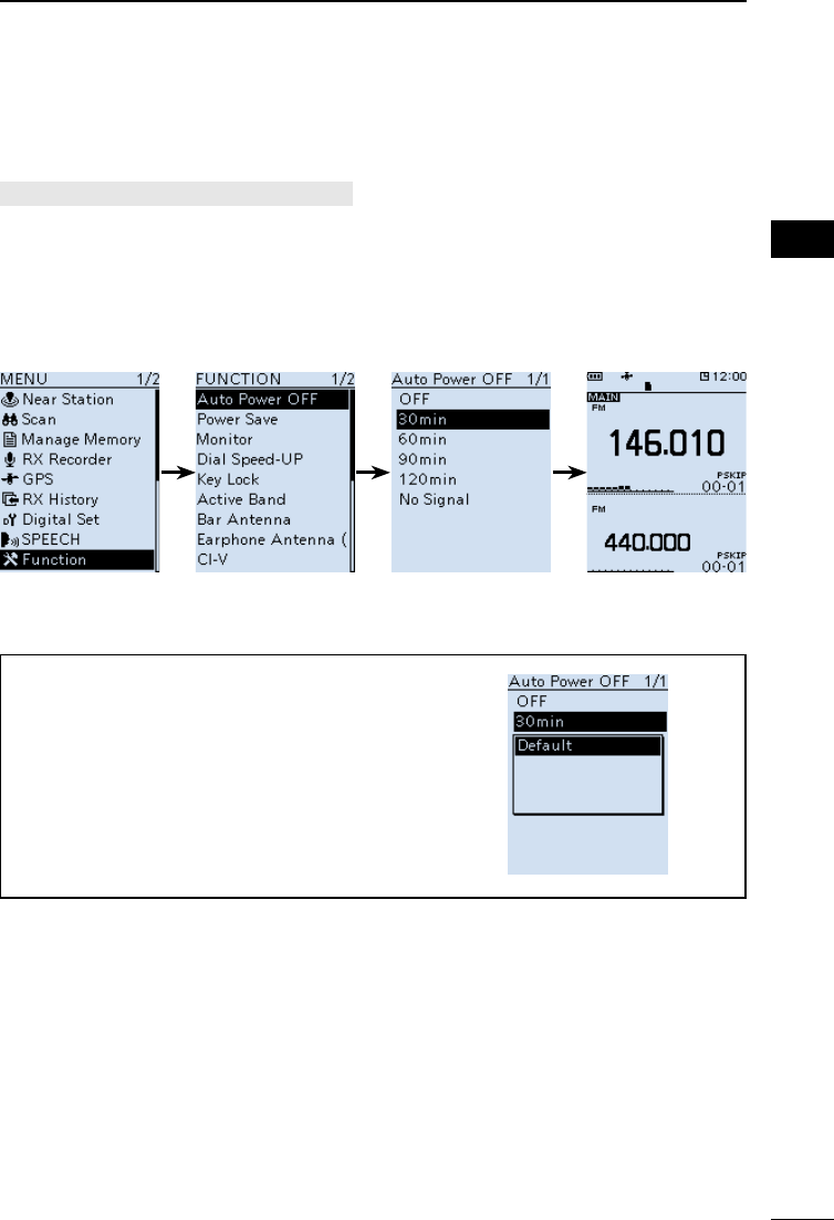
DSelecting a Menu item
Example: Set “Auto Power OFF” to “30 min.”
[MENU] > Function > Auto Power OFF
1. Push [MENU].
2. Select “Auto Power OFF” in the “Function” menu.
(Rotate [DIAL] to select it, and then push [ENTER].)
3. Select “30min,” and then push [ENTER].
• Sets the option, then goes back to the previous tree level.
4. Push [CLEAR] to return to the Main screen.
TIP: To return to the default setting
1. Push [QUICK] in step 3.
2. Select “Default,” and then push [ENTER].
• The setting returns to the default.
LThe default settings of each item are described
in ADVANCED MANUAL.
13
3BASIC OPERATION
201802
BASIC MANUAL
■Quick Menu window
You can open the Quick Menu window by pushing
[QUICK]. Selectable items in the window may differ,
depending on the selected mode or function. The items
listed below are two examples.
VFO mode Memory mode
Band Select NB*6Group Select ANL*7
MODE ANL*7MODE AFC*8
DUP AFC*8DUP SKIP
TONE*1GPS Information TONE*1GPS Information
VSC*2GPS Position VSC*2GPS Position
D.SQL*3PRIO Watch D.SQL*3Home CH Set
SCRAM*4Home CH Set SCRAM*4Display Type
ENCR*5Battery Level ENCR*5Battery Level
TS Band Scope TS Band Scope
ATT <<REC Start>> ATT <<REC Start>>
RF Gain
<<GPS Logger Only>>
RF Gain
<<GPS Logger Only>>
– – NB*6–
*1 For only FM/FM-N
*2 For only FM/FM-N/WFM/AM/AM-N
*3 For only D-STAR/P25/dPMR/NXDN-VN/NXDN-N/DCR
(Selectable options differ, depending on the receiving mode.)
*4 For only dPMR
*5 For only NXDN-VN/NXDN-N/DCR
(Selectable options differ, depending on the receiving mode.)
*6 For only USB/LSB/CW
*7 For only AM
*8 For only FM/FM-N/WFM
[QUICK]
Selectable items in the VFO mode and Memory mode
14
3
BASIC OPERATION 3
201802 201802
BASIC MANUAL
■ Setting the squelch level
Noise squelch enables the audio to be heard only while
receiving a signal that is stronger than the set level. A
higher level blocks weak signals, which enables you to
receive only stronger signals. A lower level enables you to
hear weak signals.
L“Noise squelch” is abbreviated to “Squelch” in this manual.
While holding down [SQL], rotate [DIAL] to select the
squelch level.
• “ ” is displayed.
LInformation
• Options: “OPEN,” “AUTO” (default), and “LEVEL 1” ~
“LEVEL 9”
• “LEVEL 1” is loose squelch (for weak signals) and
“LEVEL 9” is tight squelch (for strong signals).
• “AUTO” is an automatic level adjustment using a noise pulse
counting system.
• “OPEN” is the continuously open setting.
• This option is not selectable in the Digital (D-STAR, P25,
dPMR, NXDN-VN, NXDN-N, or DCR) mode.
[DIAL]
[SQL]
■Monitor function
The Monitor function is used to listen to weak signals
without changing the squelch setting.
While holding down [SQL], the receiver monitors weak
signals on the frequency.
TIP: You can set the Monitor Hold function on the MENU
screen. The receiver opens or closes the squelch each
time you push [SQL].
([MENU] > Function > Monitor) The rst few segments
of the S-meter blinks.
■Speech function
The Speech function audibly announces the displayed
frequency and mode by pushing [SPEECH].
Also, you can set various Speech functions, such as the
DIAL Speech function or Mode Speech function on the
MENU screen.
([MENU] > SPEECH > DIAL SPEECH)
([MENU] > SPEECH > MODE SPEECH)
[SPEECH]
15
3BASIC OPERATION
201802
BASIC MANUAL
■Setting the frequency
DDirectly entering a frequency
You can set the frequency with the keypad.
1. Push [VFO/MR] to select the VFO mode.
2. Push [F-INP].
3. Start entry with the MHz digits.
• When you nish entering the 1 kHz digit, a beep sounds
and the entered frequency is set.
LInformation
• If you want to change the digits from 100 kHz or below,
enter [.] and then enter the digits.
• If you push [ENT] when the digits from 100 kHz or
below are not entered, “0” is automatically entered into
the blank digits.
(Example: [1], [4], [5], [ENTER] → 145.000 (MHz))
• If you enter a frequency out of range, an error beep
sounds.
• Settable receiving bands differ on the A band and B
band. (p. 17)
Keypad
[MHz]
DChanging the frequency in MHz steps
You can change the frequency in ‘MHz’ steps for quick
tuning.
1. Push [VFO/MR] to select the VFO mode.
2. Push [MHz].
• The 1 MHz digit blinks.
3. Rotate [DIAL].
• The frequency changes in 1 MHz steps.
4. Push [MHz].
• Sets the frequency, and then returns to the Main
screen.
16
3
BASIC OPERATION 3
201802 201802
BASIC MANUAL
DSelecting the tuning step
When you select the frequency by rotating [DIAL] in the
VFO mode, it changes in the selected tuning step.
1. Push [VFO/MR] to select the VFO mode.
2. Push [TS].
3. Select a tuning step.
(Rotate [DIAL] to select it, and then push [ENTER].)
4. Push [TS].
• Returns to the Main screen.
*1 For only the AIR band.
*2 For only the BC band.
This receiver has 2 Frequency Selecting modes. You can change modes by pushing
[VFO/MR].
0.01 kHz 12.5 kHz
0.1 kHz 15.0 kHz
1.0 kHz 20.0 kHz
3.125 kHz 25.0 kHz
5.0 kHz 30.0 kHz
6.25 kHz 50.0 kHz
8.33 kHz*1 100.0 kHz
9.0 kHz*2 125.0 kHz
10.0 kHz 200.0 kHz
■Selecting the Frequency Selecting mode
VFO mode display
Memory mode display
DVariable Frequency Oscillator (VFO) mode
You can set the frequency by rotating [DIAL], or by directly
entering it with the keypad.
DMemory mode
You can set the frequency by selecting a preset channel,
using [DIAL] or keypad.
L In the Memory mode, “MR” and Memory Channel number
are displayed.
17
3BASIC OPERATION
201802
BASIC MANUAL
■Selecting the receive mode
1. Push [MODE].
• The Receive Mode options are displayed.
2. Select the Receive mode.
• The selected mode is displayed.
NOTE:
Selectable receive mode differs, depending on the band.
• A band (1300 MHz and below): All modes*.
• A band (1300 MHz or higher): FM/FM-N/WFM/AM/AM-N.
• B band: FM/FM-N/AM/AM-N/Digital modes.
* “WFM” is not selectable, depending on the receiver
version and receive frequency.
FM
Analog
mode
FM-N
WFM
AM
AM-N
LSB
USB
CW
CW-R
D-STAR
Digital
mode
P25
dPMR
NXDN-VN
NXDN-N
DCR
■Selecting the receive band
1. Push [VFO/MR] to select the VFO mode.
2. Push [BAND].
• The Receive Band options are displayed.
• The frequency set last time is displayed.
3. Select the Receive band.
• The selected band is displayed.
[BAND]
L On the B band, you can
select only AIR, 146 MHz,
370 MHz, and 440 MHz
bands.
Default display Band name
1.620 BC band
5.000 5 MHz band
51.000 51 MHz band
88.000 FM band
120.000 AIR band
146.010 146 MHz band
370.000 370 MHz band
440.000 440 MHz band
850.000 850 MHz band
1295.000 1200 MHz band
2425.000 2400 MHz band
18
3
BASIC OPERATION 3
201802 201802
BASIC MANUAL
■DIAL/VOL Switch function
You can switch the functions assigned to [DIAL] and
[▲]/[▼].
zPush [DIAL SEL] to switch the functions assigned to
[DIAL] and [▲]/[▼].
LInformation
• “ ” is displayed when the Volume Adjustment
function is assigned to [DIAL].
• Push [DIAL SEL] again to return to the previous setting.
• Even if the Volume Adjustment function is assigned to
[DIAL], you can set a squelch level by using [DIAL].
• In this manual, all instructions are described without this
setting.
■Attenuator
The Attenuator prevents a desired signal from becoming
distorted when a very strong signal is near the frequency,
or when near a very strong electric eld.
1. Push [ATT].
• The Attenuator options are displayed.
2. Set the Attenuator level to between “ATT1” to “ATT3.”
LThe higher the level, the larger the attenuation amount
becomes.
[DIAL SEL]
[ATT]
■Setting the RF gain
Set the sensitivity level to receive. Normally, set the RF
gain to maximum (“RFG MAX”).
1. Push [QUICK].
2. Select “RF Gain,” and then push [ENTER].
3. Select the level.
LOptions: “RFG1” ~ “RFG9” and “RFG MAX” (default)
LWhen “RFG MAX” is selected, nothing is displayed.
19
3BASIC OPERATION
201802
BASIC MANUAL
■Dualwatch function
Dualwatch function simultaneously monitors two
frequencies. The IC-R30 has 2 independent receiver
circuits, A band and B band. You can set different
frequencies or receive modes in each band.
LIn the A band, you can select any frequency. In the B
band, you can select only the AIR, 146 M, 370 M, or 440 M
frequency bands.
LWhen the Dualwatch function is ON, the audio output
may be interrupted when the frequency is switched while
scanning, or by other factors.
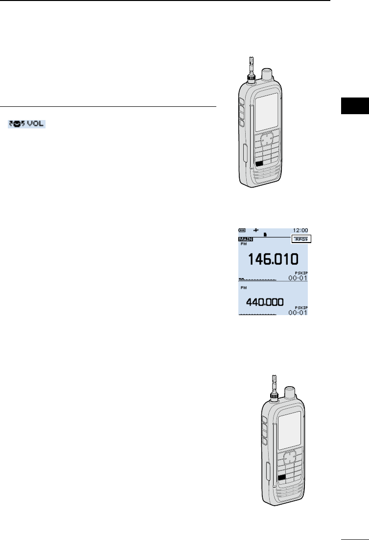
DTurning Dualwatch function ON or OFF
Hold down [DUAL] for 1 second to turn the Dualwatch
function ON or OFF.
LInformation
• When the Dualwatch function is ON, the display shows the A
band in the upper half and the B band in the lower half.
• “MAIN” is displayed on the MAIN band where you can
change the settings.
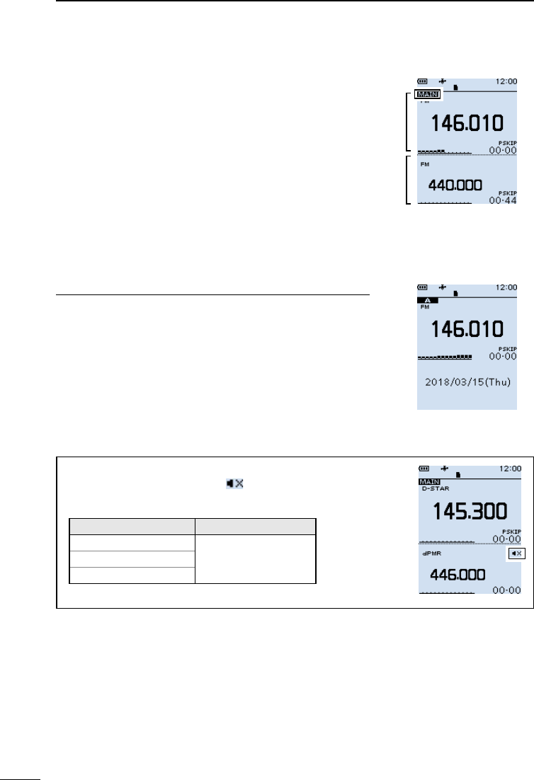
• When the Dualwatch function is OFF, the display shows only
the MAIN band. Push [MAIN] to select A or B band.
• The SUB band can be automatically muted.
([MENU] > Sounds > Sub Band Mute (Main RX))Single band display
(Dualwatch function OFF)
TIP: Depending on the receive mode, the SUB band audio
signal is muted. In such case, “ ” is displayed.
• SUB band mute status
MAIN band SUB band
LSB/USB
Digital modes*
CW/CW-R
Digital modes*
*Except when D-STAR is selected on the Dualwatch screen.
Dual band display
(Dualwatch function ON)
MAIN
band
SUB
band
20
3
BASIC OPERATION 3
201802 201802
BASIC MANUAL
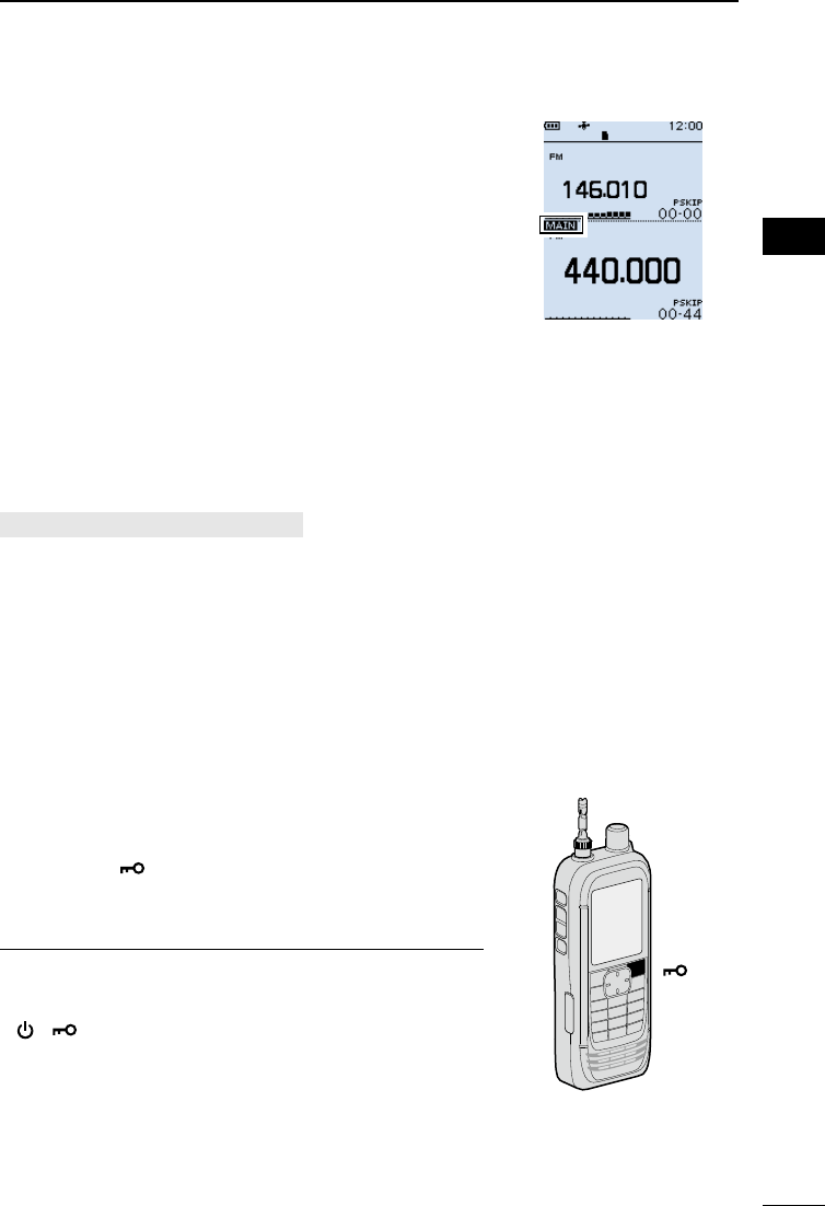
DSelecting the MAIN band
Push [MAIN] to alternately set the upper band or lower
band to the MAIN band.
• “MAIN” is displayed on the MAIN band where you can
change the settings.
LBand selection, receive frequency setting, receive mode
selection, Memory channel selection, the Memory Write
operation, the Band Scope operation can be made on only
the MAIN band.
DSetting the volume for Dualwatch
The volume setting for Dualwatch can be separately set
for each band on the MENU screen.
[MENU] > Sounds > A/B Vol Link
1. Push [MENU].
2. Select “A/B Vol Link,” in the “Sounds” menu.
(Rotate [DIAL] to select it, and then push [ENTER].)
3. Select “A/B Separate,” and then push [ENTER].
LPush [CLEAR] to return to the Main screen.
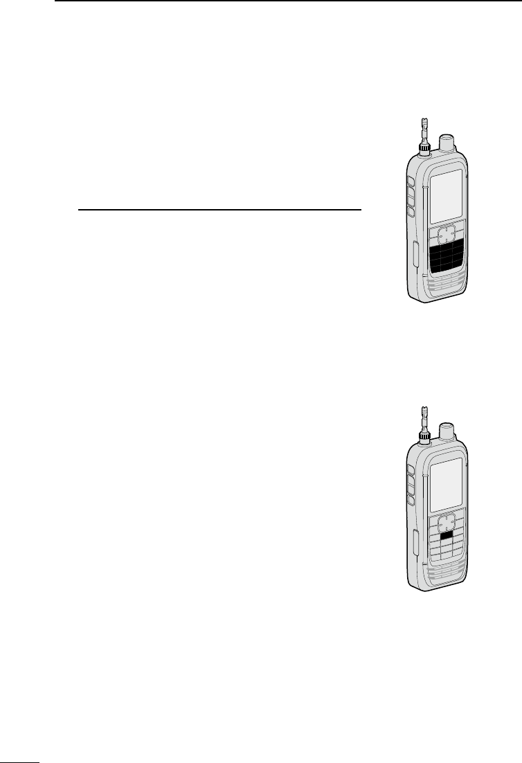
■Key Lock function
Activate to prevent accidental frequency changes and
unnecessary function access.
zHold down [ ] for 1 second to turn ON the Key Lock
function.
• When the Key Lock function is ON and the locked key or
[DIAL] is pushed or rotated, “LOCK ON” is displayed.
LInformation
• To turn OFF the function, hold down [LOCK] for 1 second
again (Until “LOCK OFF” is displayed).
• [ ], [ ], [SQL], and [▲]/[▼] (volume adjustment) can be
used even if the Key Lock function is ON.
• You can change the keys to be locked on the MENU screen.
([MENU] > Functions > Key Lock)
[ ]
B band is set to
the MAIN band

21
3BASIC OPERATION
201802
BASIC MANUAL
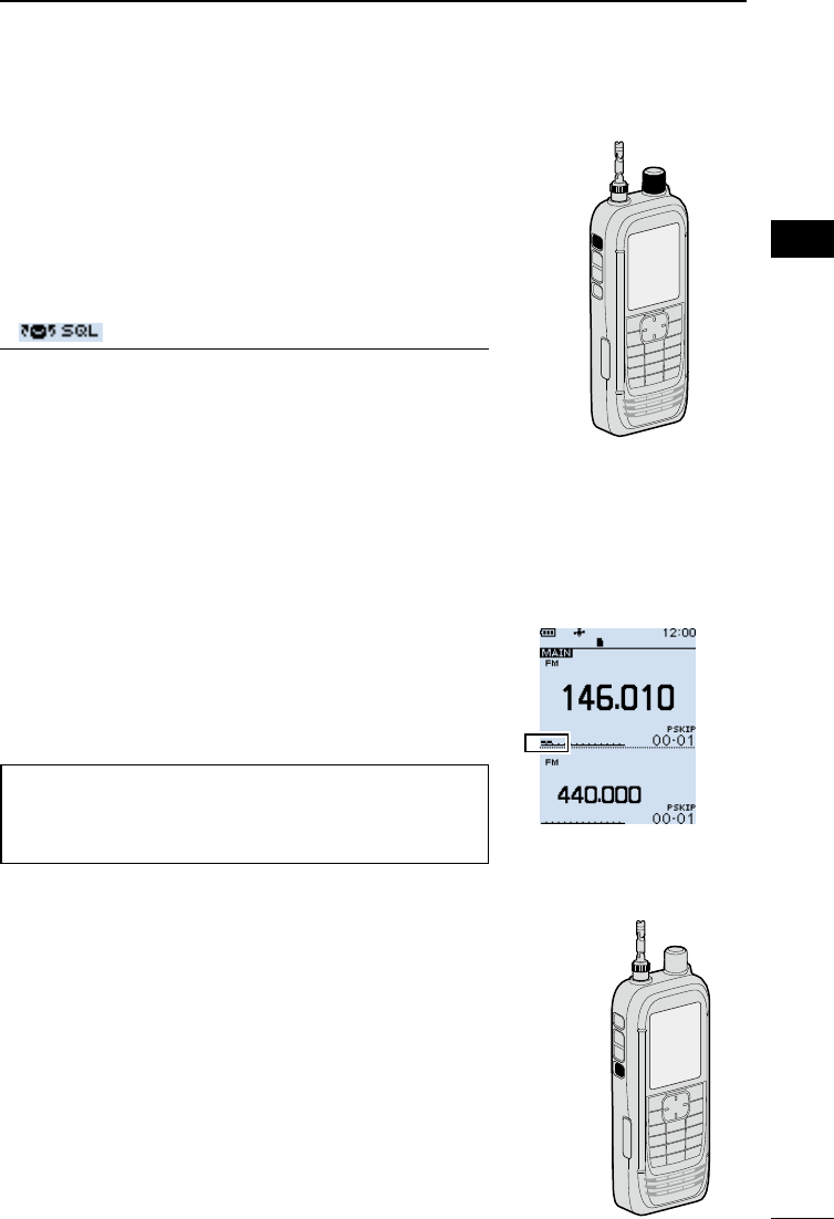
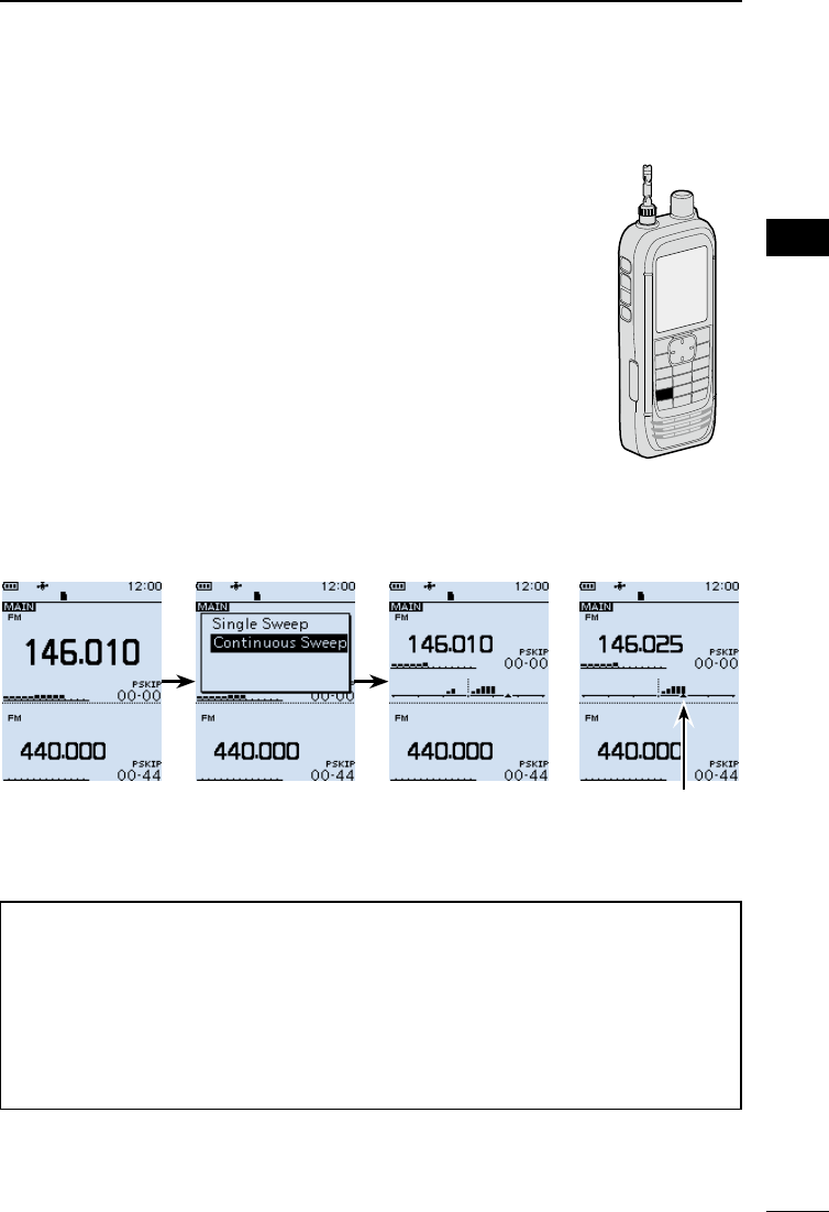
■Band Scope function
Use the Band Scope function to visually search for a specied frequency range around
the displayed frequency. You can use this function to search for a signal, and see the
relative received signal strength level.
The Band Scope function has 2 sweep types.
• Single Sweep: Searches the specied frequency range only once. The Single
Sweep starts from the lower frequency and the sweep stops after
reaching to the upper frequency.
• Continuous Sweep: Repeatedly searches the specied frequency range.
The receiver’s sweep bandwidth is ± 15 × the tuning step number, centered on the
displayed frequency.
LThe ± 15 times is a xed value.
Example:
The displayed frequency is 146.000 MHz and the tuning step is set to 5 kHz. Therefore,
the sweep range is between 145.925 MHz (lower edge frequency) and 146.075 MHz
(higher edge frequency).
See the calculation below.
Lower edge frequency = –15 × 5 kHz
= –75 kHz (–0.075 MHz)
Higher edge frequency = +15 × 5 kHz
= +75 kHz (+0.075 MHz)
• The displayed (center) frequency is 146.000 MHz
• The lower (start) frequency is 145.925 MHz
(= 146.000 MHz – 0.075 MHz)
• The higher (stop) frequency is 146.075 MHz
(= 146.000 MHz + 0.075 MHz)
Example: A strong signal is received on 146.025 MHz.
(Tuning step: 5 kHz)
Sweep marker
146.035MHz
Band scope display
Strong level
Weak level
Center frequency
(146.010)
22
3
BASIC OPERATION 3
201802 201802
BASIC MANUAL
DSweep operation
Example: Continuous sweeps centered on 146.010 MHz
1. Push [VFO/MR] to select the VFO mode.
2. Rotate [DIAL] to set 146.010 MHz.
3. Push [SCOPE].
4. Select “Continuous Sweep.”
(Rotate [DIAL] to select, and then push [ENTER].)
• Returns to the frequency display and starts the
continuous sweep.
5. Push [CLEAR].
• Stops the sweep.
6. Rotate [DIAL] to move the sweep marker to a
detected signal.
• You can hear the signal audio.
LPushing [SCOPE] and then selecting “Center Recall”
returns the sweep marker to the center frequency.
7. Push [SCOPE].
8. Select “Scope OFF,” and then push [ENTER].
• Turns OFF the Band Scope function.
Sweeping After stopping
the sweep, move
the marker to a
detected signal.
TIP:
• If the tuning step is set too wide, the signals in the sweep range may not be displayed
(they may be skipped), even if they are strong signals. Therefore, we recommend that
you set the tuning step to 20 kHz or less to use the Band Scope function.
• During a sweep the frequency range of 108.000 ~ 520.000 MHz, the displayed
frequency’s audio is output. (When the receive mode is set to WFM, LSB, USB, CW or
CW-R, the audio is not output.)
You can turn OFF the audio output on the MENU screen.
([MENU] > Sounds > Scope AF Output)
[SCOPE]

201802
23
BASIC MANUAL
4RECORDING AND PLAYING BACK
■About the microSD card
The microSD and microSDHC cards are not supplied by Icom. User supplied.
You can use a microSD card of up to 2 GB, or an microSDHC card of up to 32 GB. Icom
has checked the compatibility with the following microSD and microSDHC cards.
(As of April 2018)
Brand Type Memory size
SanDisk®
microSD 2 GB
microSDHC
4 GB
8 GB
16 GB
32 GB
L The performance of the cards listed above is not guaranteed.
L Throughout the rest of this document, the microSD card and an microSDHC card are simply
called the microSD card or the card.
LIf you use a brand new microSD card, be sure to format it. (p. 5)
NOTE:
• Before using the microSD card, thoroughly read the card’s instructions.
• Before removing the microSD card while the receiver’s power is ON, do the removal
procedure. (p. 26)
• If any of the following occurs while the card is being accessed, the card data may be
corrupted or deleted.
- You remove the microSD card from the receiver.
- You remove the battery pack or case.
- The battery is exhausted.
- The power supply from an external power source is disconnected.
• Do not touch the contacts of the card.
• The receiver takes a longer time to recognize a large capacity card.
• The card will get warm if continuously used for a long period of time.
• The card has a certain lifetime, so data reading or writing may not be possible after
using it for a long period of time. When reading or writing data is impossible, the card’s
lifetime has ended. In that case, use a new one.
We recommend you make a separate backup le of the important data onto your PC.
• Icom is not be responsible for any damage caused by data corruption of a card.
24
4
RECORDING AND PLAYING BACK 4
201802 201802
BASIC MANUAL
■Setting the Record operation
You can select to record the received audio from only the main band or both the main and
sub bands.
[MENU] > RX Recorder > Recorder Set > REC Operation
1. Push [MENU].
2. Select “REC Operation” in the “RX Recorder” menu.
(Rotate [DIAL] to select it, and then push [ENTER].)
3. Select “A/B Separate” or “A/B Link.” (default: A/B Link)
“A/B Separate”: Only audio signal received on the band that is set as MAIN (A or B)
is recorded.
“A/B Link”: Audio signals received on either or both MAIN and SUB band (Both
A and B) are recorded.
LPush [CLEAR] to return to the Main screen.
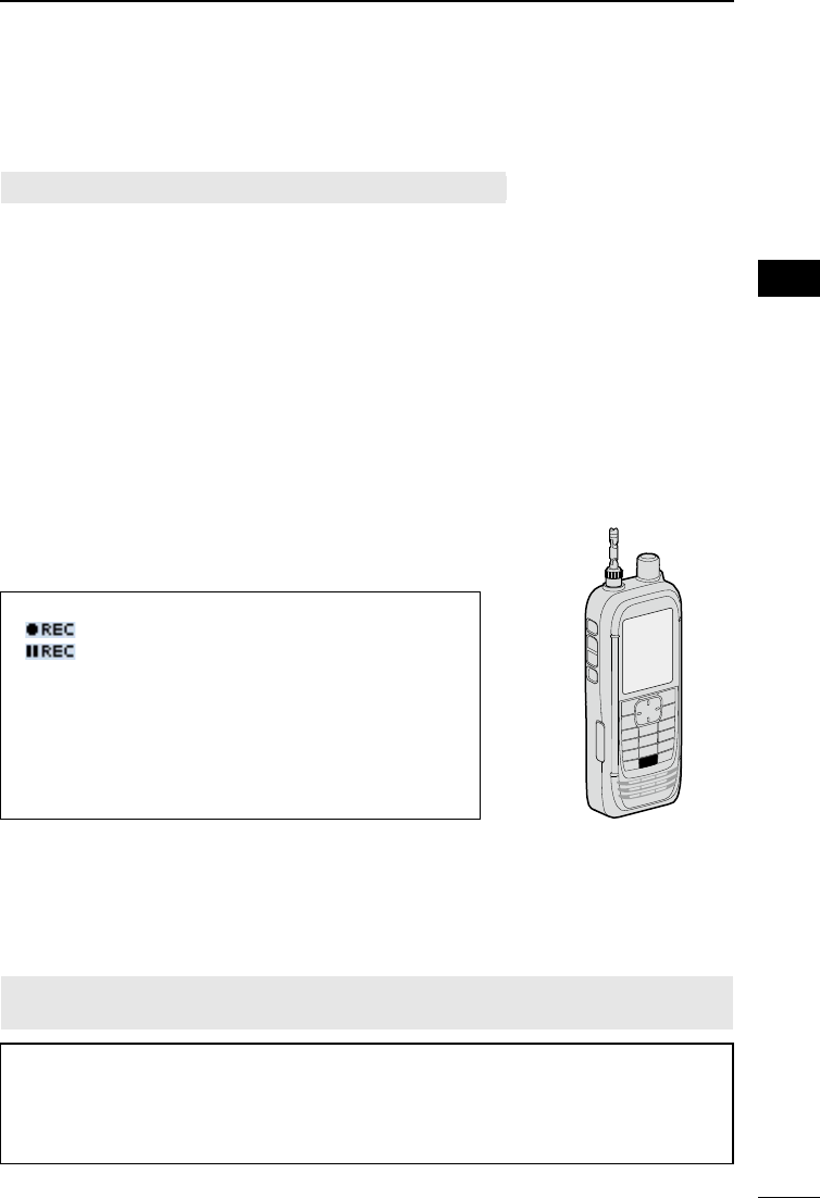
■Recording
DStarting recording
zPush [zREC].
• “Recording started...” is briey displayed.
TIP:
• “ ” is displayed during recording.
• “ ” is displayed while recording is paused.
• If a single band display is selected, only the audio
signal received on the band is recorded, even when the
“REC Operation” item is set to “A/B Link.”
• The recording continues until you push [zREC], or the
free space on the microSD card has run out.
• When the recording le’s content reaches 2 GB, the
receiver continues to record, but to a new le.
DStopping recording
1. Push [zREC] again.
• A conrmation dialog is displayed.
2. Select “YES,” and then push [ENTER].
• “Recording stopped.” is briey displayed.
NOTE: Once the recording starts, it will continue even if the receiver is turned OFF and
ON again.
TIP:
As the default setting, the recording is paused while the squelch is closed, and resumes
when a signal is received. But you can set to continue recording even while no signal is
received. (See section 6 of the ADVANCED MANUAL.)
([MENU] > RX Recorder > Recorder Set > RX REC Condition)
[zREC]
25
4RECORDING AND PLAYING BACK
201802
BASIC MANUAL
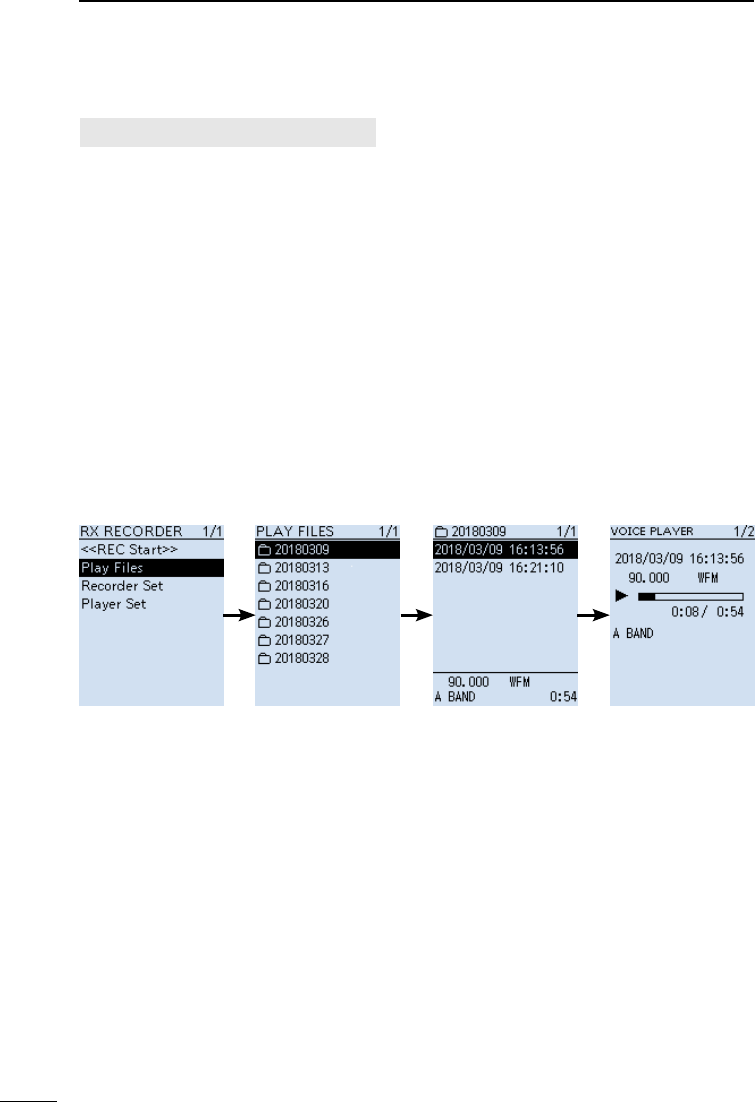
■Playing back
[MENU] > RX Recorder > Play Files
1. Push [MENU].
2. Select “Play Files” in the “RX Recorder” menu.
(Rotate [DIAL] to select it, and then push [ENTER].)
• The folder list is displayed.
3. Select a folder that contains the file you want to playback, and then push [ENTER].
• The le list is displayed.
LThe folder is named in the following manner, “yyyymmdd (yyyy: Year, mm: month, dd:
day).
4. Select a file, and then push [ENTER].
• The VOICE PLAYER screen appears and starts playing back the audio.
LPush [ENTER] to pause while playing.
LOn the VOICE PLAYER screen, you can select the le to play by pushing D-pad (Up)
or (Down).
5. Push [CLEAR] to stop playing.
• The le list is displayed.
LPush [CLEAR] again to return to the Main screen.

26
4
RECORDING AND PLAYING BACK 4
201802 201802
BASIC MANUAL
■Removing the MicroSD card
DRemoving when the receiver is OFF
1. Turn OFF the receiver.
2. Pull down the [microSD] card slot cover.
3. Push in the microSD card into the slot until a click sounds.
• The card is unlocked, and you can pull it out.
LDo not touch the contacts of the card.
4. Close the [microSD] card slot cover.
DRemoving when the receiver is ON
[MENU] > SD card > Unmount
1. Push [MENU].
2. Select “Unmount” in the “SD Card” menu.
(Rotate [DIAL] to select it, and then push [ENTER].)
• The unmount conrmation dialog appears.
3. Select “YES,” and then push [ENTER].
• “Unmount is completed.” is displayed.
4. Push in the microSD card until a click sounds, then pull it out. (See the above
illustration.)
LPush [CLEAR] to return to the Main screen.
NOTE: Close the microSD card slot cover rmly,
after removing or inserting microSD card.
Otherwise dust or water may get into the receiver,
and they can damage the receiver.
Close the slot cover rmly
YES NO
201802
27
BASIC MANUAL
5MEMORY CHANNELS
■Selecting a memory channel
Rotate [DIAL] in the Memory mode to select a Memory channel.
LThe memory contents on the screen may differ, according to the presetting.
1. Push [VFO/MR] to select the Memory mode.
LEach push toggles between the Memory mode and the VFO mode.
LPush [BAND] to display the Memory Group list, if necessary to select a group.
2. Rotate [DIAL] to select a Memory channel.
LOnly the Memory channels that have contents are displayed.
LTo select the Memory channel from the keypad, push [F-INP] then enter the Memory
channel number.
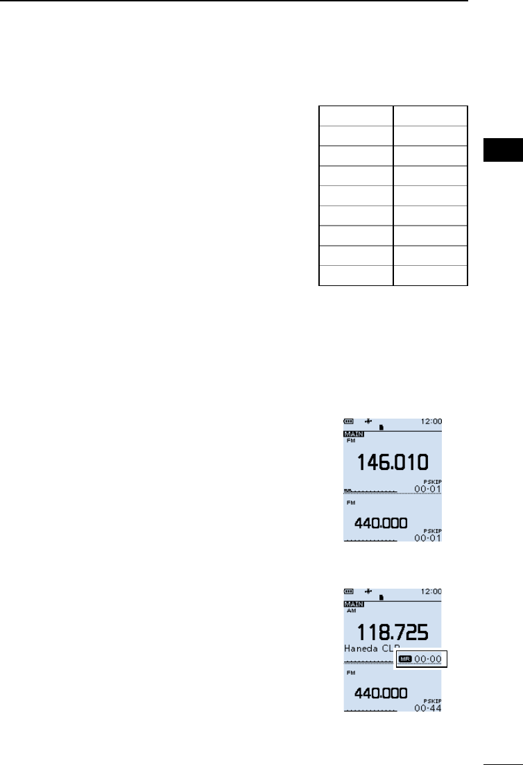
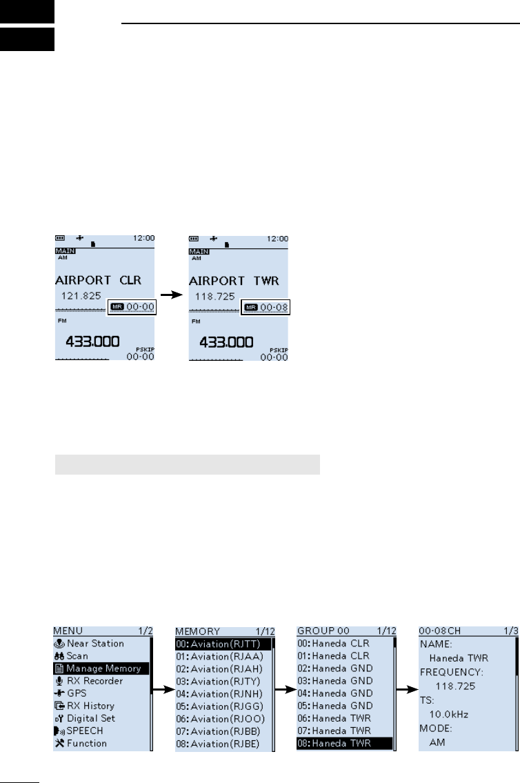
■Viewing the memory channel contents
You can view the Memory channel contents on the [Manage Memory] screen.
[MENU] > Manage Memory > Memory Channel
Example: Viewing the contents of Channel 8 in Group 00.
1. Push [MENU].
2. Select “Manage Memory.”
(Rotate [DIAL] to select it, and then push [ENTER].)
3. Select Memory Channel Group “00,” and then push [ENTER].
4. Select Memory Channel “08,” and then push [ENTER].
• Channel contents are displayed.
LRotate [DIAL] to scroll the screen.
LPush [CLEAR] to return to the Main screen.
Group list List of Memory
Channels in Group 00
Contents of Memory
Channel 08
28
5
MEMORY CHANNELS 5
201802 201802
BASIC MANUAL
■Writing a new memory channel
A single memory channel stores the frequency, receive mode
and so on, for quick recall.
The following is the basic memory writing procedure.
LRefer to ADVANCED MANUAL for memory writing details.
LSee Section 3 for the receive frequency or receiving mode
setting procedures.
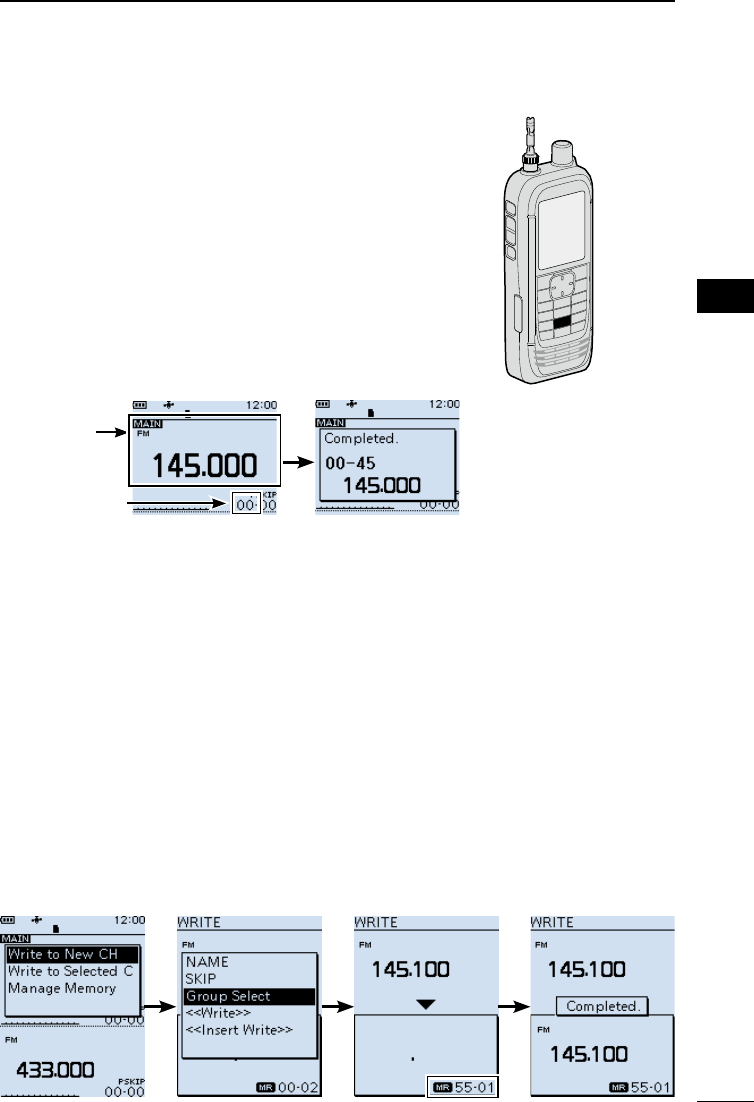
DWriting to a blank channel
Example: Writing “145.000 MHz” in the “FM” mode to a
blank channel in a selected group.
zHold down [MW] until 2 beeps sound.
• The contents such as frequency and operating mode are
briey displayed, then written to a blank channel (45) in the
selected group (00).
DWriting to a specied channel in a specied group
Example: Writing “145.100 MHz” in the “FM” mode into channel 01 in group 55.
1. Push [MW].
2. Select “Write to New CH.”
(Rotate [DIAL] to select it, and then push [ENTER].)
3. Push [QUICK].
4. Select “Group Select,” and then push [ENTER].
5. Select group “55,” and then push [ENTER].
6. Rotate [DIAL] to select channel “01.”
• The selected channel blinks.
7. Push [MW].
• The writing conrmation dialog appears.
8. Select “YES.”
• The contents to be written into the channel are briey displayed, then are written into
channel “01” in group “55.”
[MW]
Contents
to be written
Memory group
to belong

201802
29
BASIC MANUAL
6SCANNING
■Scan type
Scanning is a versatile function that can automatically search for signals. A scan makes it
easier to locate stations to listen to, or to skip unwanted channels or frequencies.
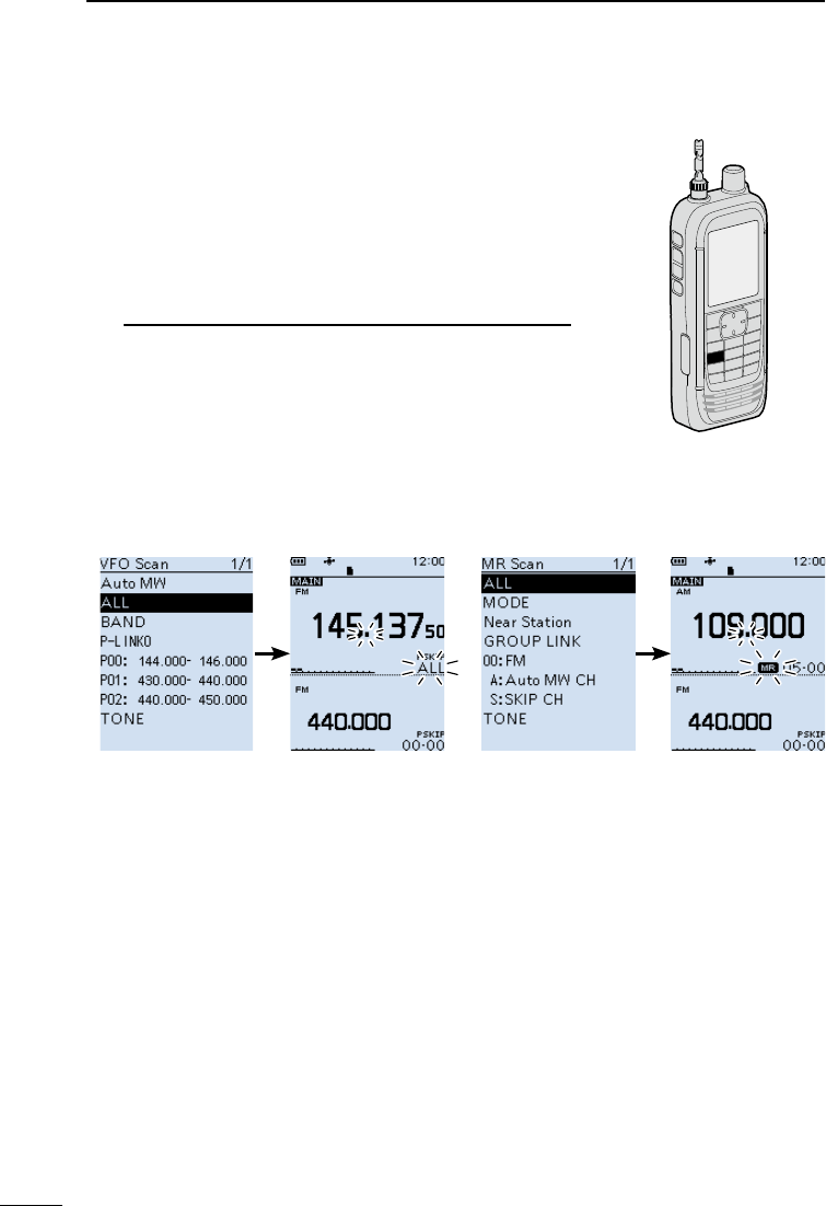
DVFO scan (p. 32)
In the VFO mode, the VFO scan searches a signal within the specied frequency range.
Scan type Description
Auto MW When a signal is received during a VFO scan, the frequency is
automatically stored into an Auto Memory Write channel group (A000
~ A199).
ALL Repeatedly scans the entire frequency range.
BAND Repeatedly scans the selected band.
P-LINK 0 ~ 9 Sequentially scans several Program Scan ranges.
The links are set on the MENU screen.
([MENU] > Scan > Program Link)
P00 ~ 49 Repeatedly scans the Program Scan range.
The scan edges are set on the Menu screen.
([MENU] > Scan > P-Scan Edge)
DMemory scan (p. 36)
In the memory mode, the memory scan searches a signal on the preregistered memory
channels.
Scan type Description
ALL Scans all Memory channels.
Mode Scans Memory channels which are entered with the same receiving
mode as the currently selected mode.
Near Station Searches for near stations that are within 160 kilometer (100 miles)
from your location using your GPS position and the station’s position
that is entered in the memory channels.
GROUP LINK Sequentially scans the memory groups which are set to link on the
MENU screen.
GROUP Scans the Memory channels in the selected group.
(GROUP 00 ~ 99, A: Auto MW CH, S: SKIP CH)
DTone scan
The Tone scan searches for signals in tone frequencies or DTCS codes that are used by
stations using the Tone Squelch function.
See ADVANCED MANUAL for its operation.
LA Tone scan is usable in either VFO or Memory channel mode.
LDuring a scan, rotate [DIAL] to change the scan direction.
See “Tone squelch operation” or “DTCS code squelch operation” for details on
ADVANCED MANUAL.

30
6
SCANNING 6
201802 201802
BASIC MANUAL
■About Scans
[DIAL] operation during a scan
• Rotate [DIAL] to change the scan
direction during a scan.
• When the scan is paused, rotate [DIAL] to
resume the scan.
Squelch setting for a scan
You can change the squelch level to suit
your operating needs. Set the squelch
level to open the squelch, according to the
received signal strength.
LDuring a scan, rotate [DIAL] while holding
down [SQL] to adjust the squelch level.
The scan resumes after adjusting.
Tuning step for a VFO scan
The selected tuning step is applied to the
scan.
For a Program scan or Program Link scan,
set the tuning step in the Program Scan
ranges (P-Scan Edge).
Scan Skip function*
The skip function speeds up scanning by
not scanning those frequencies set as skip
channels.
In the VFO mode
The frequencies that are set as “PSKIP”
are skipped during a scan. (p. 37)
In the Memory mode
The frequencies that are set as skip
channels “PSKIP” and “SKIP” are not
scanned. (p. 37)
LYou must enter 2 or more Memory
channels to start a memory scan.
TIP: When Program Skip is set to OFF,
you cannot use the Program Skip scan
function. (p. 35)
([MENU] > Scan > Program Skip)
Receiving mode during a scan
• The VFO scan uses the selected
receiving mode.
• During a Memory mode scan, the
receiving mode entered into the channel
is used.
When signal is received
When a signal is received, the scan pauses
for this set period of time.
When a received signal disappears, the
scan resumes for this set period of time.
[MENU] > Scan > Pause Timer
[MENU] > Scan > Resume Timer
1. Push [MENU].
2. Select “Pause Timer” or “Resume
Timer” in the “Scan” menu.
3. Select an option, and then push
[ENTER].
Pause Timer*
• 2 ~ 20 sec:
When a signal is received, the
scan pauses for 2 ~ 20 seconds
(in 2 second steps).
• HOLD: The scan pauses on a
received signal until the signal
disappears.
Resume Timer*
• 0 sec: The scan resumes immediately
after the signal disappears.
• 1 ~ 5 sec:
The scan resumes 1 ~ 5
seconds after the signal
disappears.
• HOLD: The scan remains paused for
the Pause Timer setting, even
if the signal disappears.
NOTE: Rotate [DIAL] to resume the
scan. The Resume Timer must be set
shorter than the Pause Timer, otherwise
this timer does not work properly.
* These settings can be separately set to A band and B band.
31
6SCANNING
201802
BASIC MANUAL
■Starting or canceling the scan
VFO scan: Select the VFO mode and operating mode.
Memory scan: Select memory mode.
1. Push [SCAN].
• Opens the Scan Type list window.
LIf you hold down [SCAN] for 1 second, the last
selected scan starts.
2. Select a scan type.
(Rotate [DIAL] to select it, and then push [ENTER].)
LInformation
• In the VFO mode, the decimal point and the selected
Scan Type icon blink.
• In the Memory mode the decimal point and the Memory
icon blink.
• During a scan:
- Rotate [DIAL] to change the scanning direction.
- Push [SCAN] to cancel the scan.
[SCAN]
■Convenient function for a Scan
If the Skip setting is set, specied frequencies or memory
channels will be skipped during the scan.
• Skip setting for a VFO scan (p. 35)
• Skip setting for a memory channel scan (p. 37)
• Temporary skip setting (p. 35)
Scan resume setting (p. 30)
Voice Squelch Control (VSC) function (p. 45)
VFO scan list Memory scan list
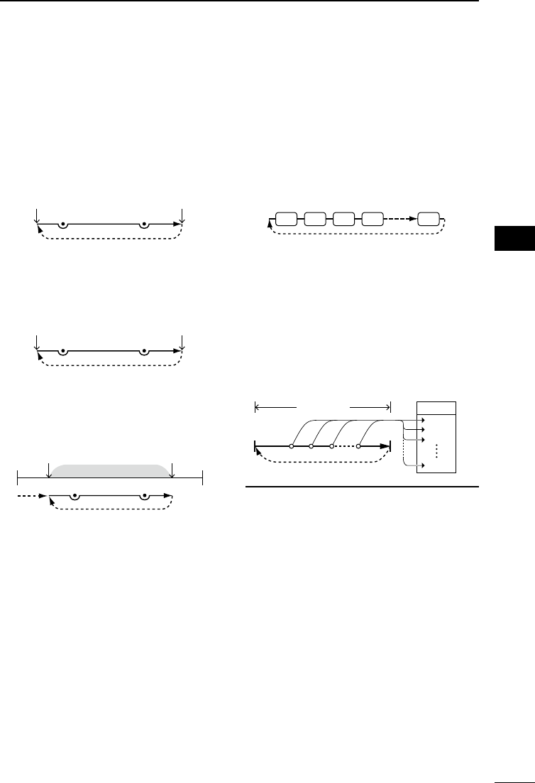
32
6
SCANNING 6
201802 201802
BASIC MANUAL
■VFO scan
The VFO scan searches for a signal within
the specied frequency range.
LSee page 31 for details of ‘Starting or
canceling the scan.’
DFull scan (ALL)
Repeatedly scans the entire band.
IC-R30 frequency
lower end
IC-R30 frequency
upper end
Scan
Jump
PSKIPPSKIP
DBand scan (BAND)
Repeatedly scans the selected band.
Band frequency
lower end
Band frequency
upper end
Scan
Jump
PSKIPPSKIP
DProgram scan (P00 ~ P49)
Repeatedly scans the selected Program
Scan range (P-Scan Edge 00 ~ 49).
Scan
Jump
Jump
Scan range
Lower edge Upper edge
PSKIPPSKIP
At least one Program Scan range (P-Scan
Edges) must be entered to start a Program
scan.
([MENU] > Scan > P-Scan Edge)
See page 33 for more details.
DProgram Link scan
(P-LINK 0 ~ 9)
Sequentially scans the Program Scan
ranges. The links are set on the MENU
screen. ([MENU] > Scan > Program Link)
See page 34 for more details.
Program scan edges (Example: P00 ~ P10)
Jump
Scan
P00 P01 P02 P03 P10
LWhile scanning, push [BAND] to move to
the next Program scan range.
DAuto memory write scan
(Auto MW)
When a signal is received during a VFO
scan, the frequency is automatically stored
into an Auto Memory Write channel group
(A000 ~ A199).
Scan
Signal received
Jump
Scan range
A000
Channels
A002
A001
A199
LInformation
• The Auto Memory Write scan writes
to a memory channel when the scan
automatically resumes.
• When no blank channels is left in the
Auto Memory Write channel group A
(000 ~ 199), the scan automatically
cancels.
• When you start this scan, you can
skip the following dialog in the Menu
screen.
“ Clear All memories in the group A?
(The Auto MW Scan will then start.)
( [MENU] > Scan > Auto MW SCAN
Memory Clear)
OFF: Writes to a blank channel in the group
A.
Display Dialog: Display dialog to conrm.
ON: Clears all memories in the group A.
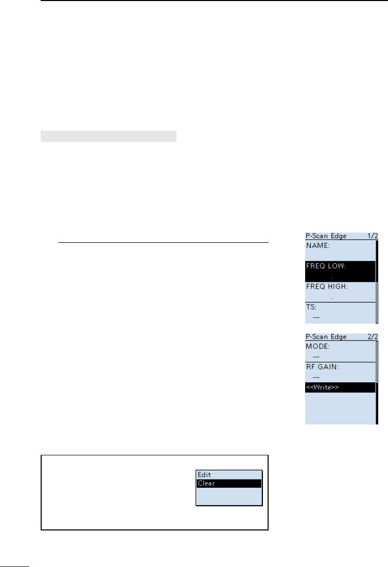
33
6SCANNING
201802
BASIC MANUAL
DEntering Program Scan ranges
You can enter the upper and lower frequency edges for a
Program scan.
Each Program Scan range has its own tuning step,
operating mode, and RF gain setting.
You can enter up to 50 Program Scan ranges (P-Scan
Edge) on the MENU screen.
[MENU] > Scan > P-Scan Edge
1. Push [MENU].
2. Select “P-Scan Edge” in the “Scan” menu.
(Rotate [DIAL] to select it, and then push [ENTER].)
3. Select a blank Program scan range “00” ~ “49.”
4. After pushing [QUICK], select “Edit” and then push
[ENTER].
• The “P-Scan Edge” screen is displayed.
5. Select “FREQ LOW” or “FREQ HIGH” to enter the
lower edge and higher edge, and then push [ENTER].
LInformation
• Rotate [DIAL] to select the item, and push [ENTER]
to enter the edit screen.
• Enter the lower edge and higher edge using the
keypad.
• When the “NAME” is entered, it displays on the
Scan Type list window. About editing character, see
ADVANCED MANUAL for details.
• When the “TS” (Tuning Step), “MODE” and/or “RF
GAIN” are blanked, they are used the current setting on
the VFO mode.
The “TS” and “MODE” must be set to match with you
desired signals, if you are not familiar with them, we
recommend to set them to “Auto.”
6. After editing contents, select “<<Write>>,” and then
push [ENTER].
• The conrmation dialog is displayed
7. Select “YES,” and then push [ENTER].
LPush [CLEAR] to return to the Main screen.
P-Scan Edge screen
TIP: Clearing a Program scan range
To clear the Program scan range,
select “Clear” at above step 4, and
then push [ENTER].
• The conrmation window is displayed,
select “YES” and push [ENTER] to
clear the Program scan range.
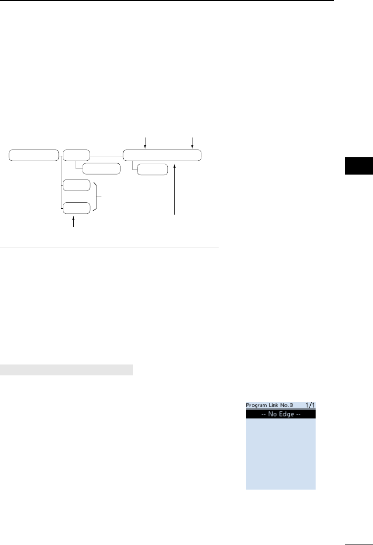
34
6
SCANNING 6
201802 201802
BASIC MANUAL
DAbout the Program Link Scan
This item sets the Link function for 2 or more Program
Scan range to sequentially scan during a Program Link
scan. The Program Link scan scans all frequencies in the
scan ranges.
Default settings of the Program Link
...
Program Link 0:
1:
9:
Edit Name
00: 430.000−450.000
Program Link number (0 to 9)
Blank
Program Scan range (PXX)
Delete
Program Scan
lower edge
Program Scan
upper edge
LInformation
• The Program Link Number screen displays the frequency
range.
• You can add a Link setting by pushing [QUICK] when
2 or more Program Scan ranges (P-Scan Edge) are
entered.
• When there is no Program Scan range (P00 ~ P49)
entered, “Add” is not displayed after pushing [QUICK].
DSetting the Program Link function
[MENU] > Scan > Program Link
1. Push [MENU].
2. Select “Program Link” in the “Scan” menu.
(Rotate [DIAL] to select it, and then push [ENTER].)
3. Select a Program Link number “0” ~ “9,” and then
push [ENTER].
• The Program Link Number screen displays the
preregistered Program Scan Ranges.
4. After pushing [QUICK], select “Add” and then push
[ENTER].
5. Select the Program scan range that you want to add.
(Rotate [DIAL] to select it, and then push [ENTER].)
6. Repeat steps 4 and 5 until all Program scan ranges
that you want, are added.
7. Push [ENTER] to save the Program Link.
LPush [CLEAR] to return to the Main screen.
LWhen no Program scan
range is selected, “-- No
Edge --” is displayed.
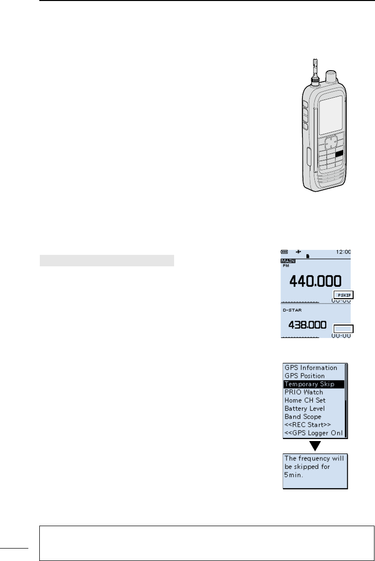
35
6SCANNING
201802
BASIC MANUAL
DStoring Skip frequencies
You can skip unnecessary frequencies during a scan.
While a scan is paused and if you want to skip the
frequency, you can store it into the Skip channel group S
(00 ~ 99) as a Skip channel (PSKIP).
The Scan Skip function speeds up a scan.
1. Start a VFO scan.
• When a signal is received, the scan pauses.
2. Hold down [SKIP] until two short beeps sound.
• The frequency is stored into the Skip channels group.
• The entered Memory channel number blinks.
• After storing, the scan resumes.
LIf there is no blank channel, an error beep sounds,
and the frequency is not stored.
DProgram Skip Scan function
This function enables the receiver to skip the unwanted
frequencies that are entered as Memory channels and are
set to “PSKIP.” (p. 37)
[MENU] > Scan > Program Skip
1. Push [MENU].
2. Select “Program Skip” in the “Scan” menu.
(Rotate [DIAL] to select it, and then push [ENTER].)
3. Select the Program Skip function, “ON” or “OFF,” and
then push [ENTER].
• When “ON” is selected,“PSKIP” is displayed above the
Memory channel number.
LPush [CLEAR] to return to the Main screen.
DTemporary Skip function
This function temporarily skips unwanted frequencies (or
memory channels) during a scan for the set period of time,
without changing the Skip Channel setting.
LYou can change Temporary Skip Timer on the MENU
screen. (Default: 5 min)
([MENU] > Scan > Temporary Skip Timer)
1. Start a scan.
• When a signal is received, the scan pauses.
2. After pushing [QUICK], select “Temporary Skip” and
then push [ENTER].
• The scan automatically resumes.
LAfter the Temporary Skip Timer period ends, the
scan is canceled or the receiver is turned OFF, the
Temporary Skip function is turned OFF.
[SKIP]
ON
OFF
TIP:
• Up to 5 Temporary Skip frequencies or Memory channels can be set. When the 6th
frequency or Memory channel is set, the oldest setting is automatically deleted.
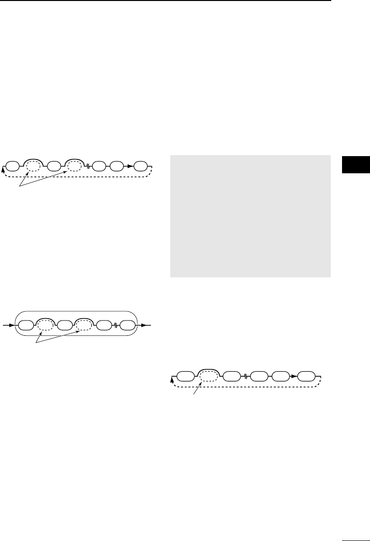
36
6
SCANNING 6
201802 201802
BASIC MANUAL
■Memory scan
The Memory scan searches a signal on the
preregistered memory channels.
LSee page 31 for details of ‘Starting or
canceling the scan.’
DAll scan (ALL)
Repeatedly scans all memory channels.
00 01 02 99 A S03
Scan
Memory Groups
(00 ~ 99, A: Auto MW CH and S: Skip CH)
Empty groups are skipped
Jump
DMode scan (MODE)
Scans Memory channels which are entered
with the same receiving mode as the
currently selected mode.
LThe Mode scan scans all memory groups.
( Group 00 ~ 99, A: Auto MW CH, S: SKIP
CH)
AM FM AM AM AMCW
Scan
Example: Scanning AM mode
Memory group 02
Modes other than AM are skipped
DNear Station scan
(Near Station)
Searches for up to 50 nearby stations that
are within 160 kilometer (100 miles) from
your location using your GPS position
data and the station’s position data that is
entered in the memory channels.
LRegardless of the SKIP setting, all memory
channels will be scanned.
NOTE:
• When using the Near Station scan, BE
SURE to rst receive your own position
data, or manually enter your position
data.
([MENU] > GPS > GPS Set > GPS Select)
• If no station is found within a 160
kilometer (100 miles) range, “No station
found.” is displayed.
• If the last received position data can be
used, “GPS is invalid. Search by last
valid position” is displayed.
DGroup Link scan
(GROUP LINK)
Sequentially scans the memory groups that
are set to link on the MENU screen.
01 02
00 A S
99
Scan
Memory Groups
(00 ~ 99, A: Auto MW CH and S: Skip CH)
Unchecked groups are skipped Jump
At least 2 groups must be checked to start
a Group Link scan.
([MENU] > Scan > Group Link)
See page 37 for more details.
DGroup scan (GROUP 00 ~ 99)
Scans the Memory channels in the selected
group. (GROUP 00 ~ 99, A: Auto MW CH,
S: SKIP CH)
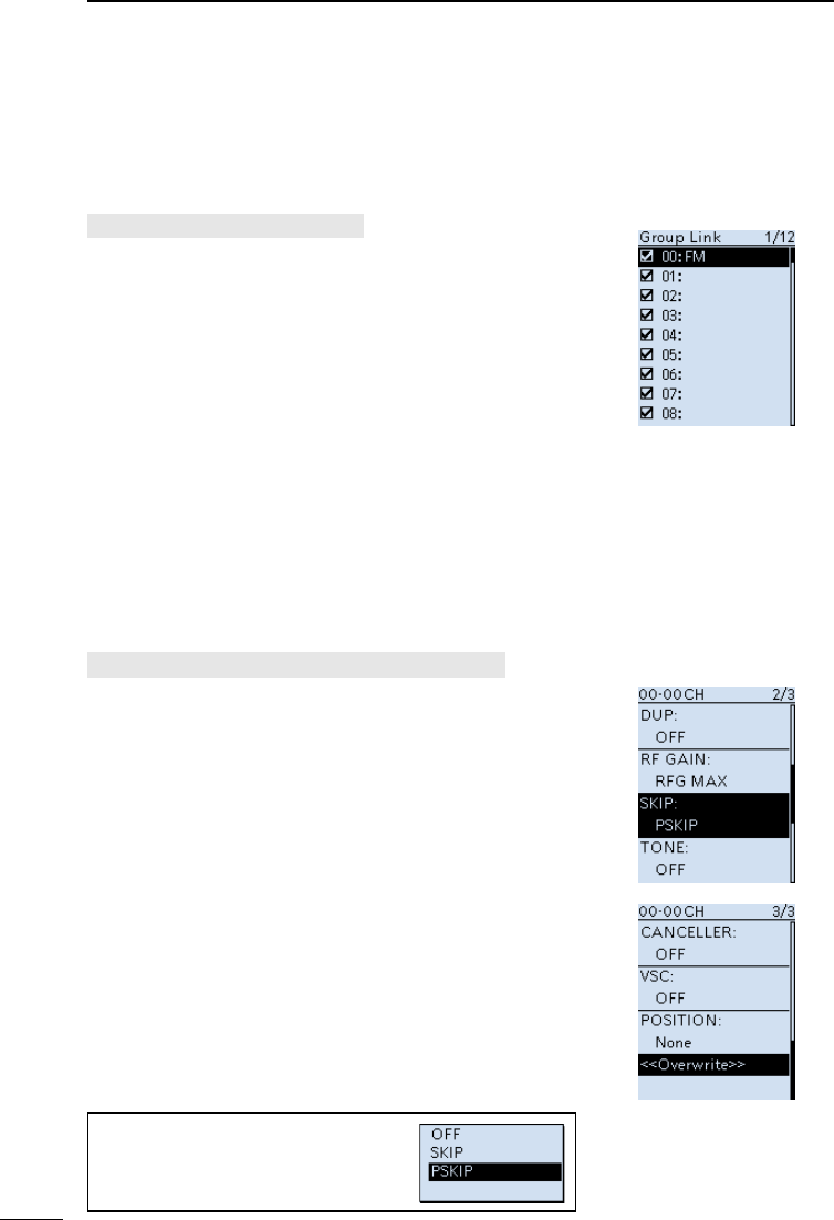
37
6SCANNING
201802
BASIC MANUAL
DSetting the Group Link
You can sequentially scan the memory groups which are
set to link on the MENU screen.
LIn the default setting, all groups are set to link.
[MENU] > Scan > Group Link
1. Push [MENU].
2. Select “Group Link” in the “Scan” menu.
(Rotate [DIAL] to select it, and then push [ENTER].)
3. Select a group, “00” ~ “99,” “A: Auto MW CH,” “S:
SKIP CH.”
4. Push [ENTER] to turn the Link function ON or OFF.
• Display “✔” when the function is set to “ON”.
LPush [QUICK] to quickly turn all the groups ON or
OFF.
LIn the default setting, all groups are set to ON.
LPush [CLEAR] to return to the Main screen. Group Link screen
DSetting the skip channel
You can set or clear a Skip Channel setting.
The channels that are set as a Skip channel are skipped
during a scan.
[MENU] > Manage Memory > (Group number)
1. Push [MENU].
2. Select the Group number in the “Memory Manage”
menu.
(Rotate [DIAL] to select it, and then push [ENTER].)
LGroup numbers are “00” ~ “99,” “A: Auto MW CH” and
“S: SKIP CH.”
3. Select the memory channel to be skipped.
4. After pushing [QUICK], select “Edit” and then push
[ENTER].
5. Select “SKIP,” and then push [ENTER].
LSelect an option, and then push [ENTER].
• OFF: Cancels the Skip Channel setting.
• SKIP: Skipped during a Memory scan.
• PSKIP: Skipped during both VFO and Memory scans.
6. Select “<<Overwrite>>,” and then push [ENTER].
• The conrmation dialog is displayed, select “YES” and
push [ENTER] to save the Memory channel.
• Select “NO” to just close the conrmation window.
LPush [CLEAR] to return to the Main screen.
Manage Memory screen
TIP:
In the Memory mode operation, you
can change the SKIP setting by
pushing [SKIP].
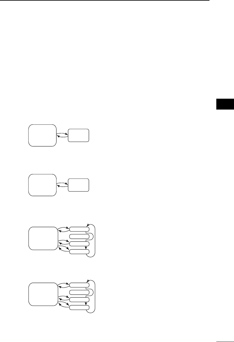
38
6
SCANNING 6
201802 201802
BASIC MANUAL
■About the Priority Watch function
While operating in the VFO mode, or while in the VFO scan, the Priority watch function
shortly checks for signals on a selected memory channel (frequency) every 5 seconds.
There are 4 ways to use the Priority Watch function, as described below.
LWhen the Dualwatch function is ON, you can independently scan on the MAIN band and
SUB band.
LWhile operating the Priority Watch function, you can change the Operating Band, frequency
(using [DIAL]), receiving mode, and so on. Also you can start or cancel the VFO scan.
The Priority Watch function is canceled when:
• Starting the Band scope. (p. 21)
• Either the [CLEAR], [MW], or [F-INP] keys is pushed.
• The “PRIO OFF” is selected in the Quick menu.
Watching a Priority channel while receiving in the VFO mode
Watching a Priority channel while scanning in the VFO mode
Memory scanning while receiving in the VFO mode
Memory scanning while scanning in the VFO mode
VFO
frequency
Priority
channel
Receiving
for 5 seconds
Priority
channel
VFO scan
Scanning
for 5 seconds
VFO
frequency
Receiving
for 5 seconds
SKIP
00
01
02
99
M-CH
VFO scan
Scanning
for 5 seconds
SKIP
00
01
02
99
M-CH
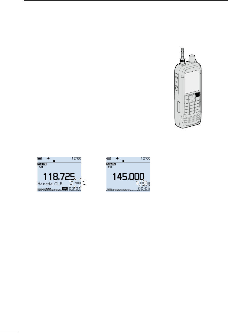
39
6SCANNING
201802
BASIC MANUAL
You can start or cancel any scans that are described on
the previous page, in the same way.
DStarting the Priority Watch
To start the Priority watch, select “ON” or “Bell,” as
described below.
• ON : When a signal is received on the Priority channel, the
channel is automatically selected.
• Bell : When a signal is received on the Priority channel,
beeps sound and the “S” icon blinks.
1. Select the Priority channel or Scan type in the
Memory mode.
2. Push [QUICK].
3. Select “PRIO Watch” in the Quick menu.
(Rotate [DIAL] to select it, and then push [ENTER].)
4. Select the option.
• “PRIO” is displayed.
DCanceling the Priority Watch
1. Push [QUICK].
2. Select “PRIO Watch OFF” in the Quick menu.
(Rotate [DIAL] to select it, and then push [ENTER].)
• “PRIO” disappears.
DThe Priority Watch and Scanning
When you want to use the combination of the Priority
Watch and a scan, you start a Memory scan rst, then
start the Priority Watch, and a VFO scan in order.
1. Start a Memory scan in the Memory mode.
2. Start the Priority Watch.
• “PRIO” is displayed.
3. Start a VFO scan.
[QUICK]
■Starting or canceling the Priority Watch function
When “ON” is selected
• When a signal is received on the Memory channel
When “Bell” is selected
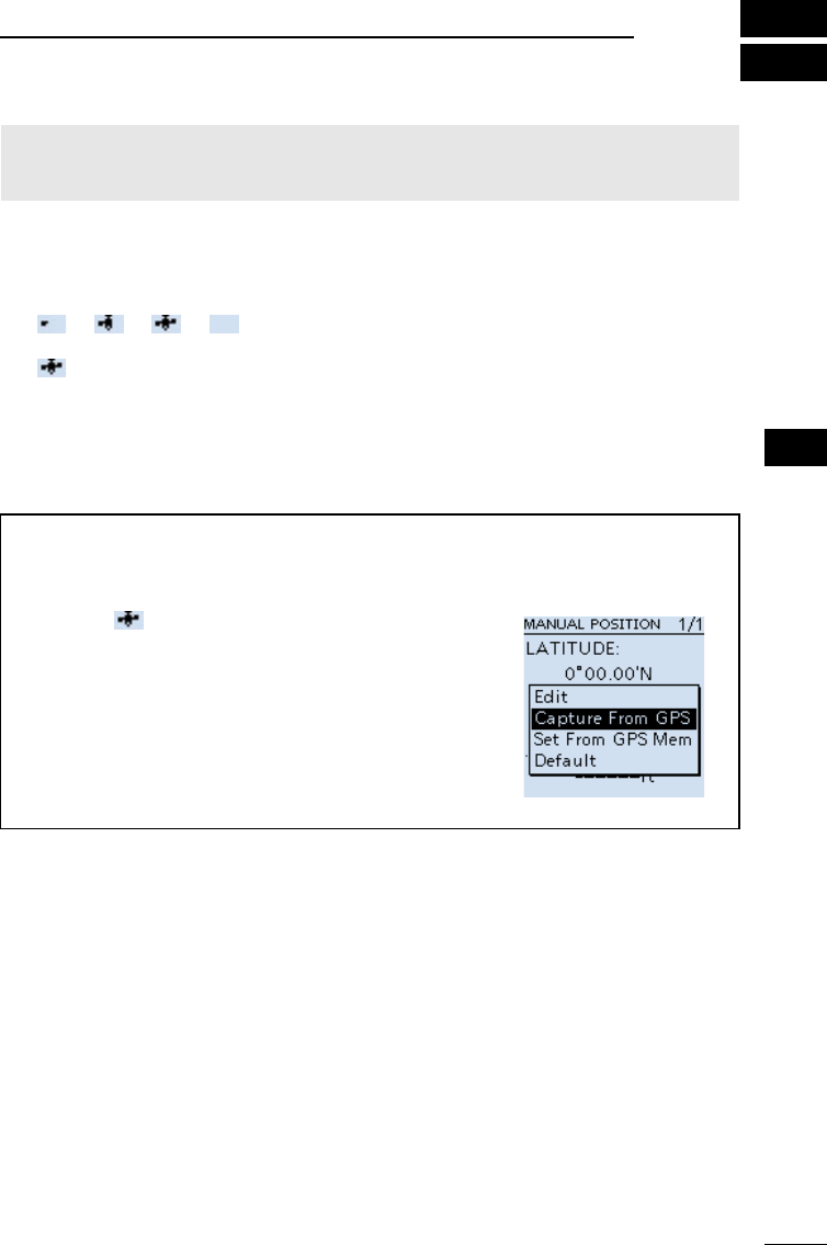
40
7
BASIC MANUAL
7
GPS OPERATION
NOTE: The built-in GPS receiver cannot calculate its location if it cannot receive signals
from the GPS satellites. Refer to ADVANCED MANUAL for more details on the GPS
function.
DChecking the GPS signal
You can check the satellite acquisition status indicated by the GPS icon.
• The GPS icon blinks when receiving.
→ → →
• The GPS icon is displayed when the current location is correctly received.
LThe time it takes to receive the GPS data may differ, depending on your location.
LThe GPS icon is not displayed when “GPS Select” is set to “Manual.”
([MENU] > GPS > GPS Set > GPS Select)
TIP: For the battery power saving
When using the receiver in the same place, you can save the battery power by manually
entering your location, or manually read the received GPS position into the MANUAL
POSITION screen.
1. Confirm is displayed. (See above)
2. Select “Manual Position” in the “GPS” menu.
([MENU] > GPS > GPS Set > Manual Position)
3. Push [QUICK], and then select “Capture From GPS” to
read the received position into the Manual position.
4. Push D-pad (Left) to return to the “GPS set” screen.
5. Set “GPS Select” to “Manual.”
([MENU] > GPS > GPS Set > GPS Select)
• The manual position is activated instead of the internal
GPS.
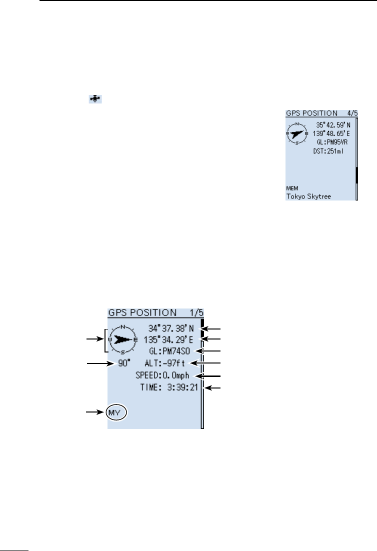
41
7GPS OPERATION
201802
BASIC MANUAL
Example:
GPS POSITION screen (MY)
Your course
heading is
East.
Your course
heading.
Latitude
Longitude
Time
Grid Locater
Altitude
Displays
My position
(Where you are)
Speed
■Checking your GPS location
You can check your current location.
DDisplaying Position Data
1. Confirm is displayed.
2. Push [QUICK].
3. Select “GPS Position.”
(Rotate [DIAL] to select it, and then push [ENTER].)
• The GPS POSITION screen is displayed.
4. Rotate [DIAL].
• Changes between the MY (My position), RX (Received
position), MEM (GPS Memory position), or ALM (GPS
Alarm position) screen.
LPush [CLEAR] to return to the Main screen.
DAbout the GPS POSITION screen
GPS Memory position
(MEM) screen

42
7
GPS OPERATION 7
201802 201802
BASIC MANUAL
■GPS Logger function
The GPS Logger function enables you to save the position data from a GPS receiver onto
a microSD card as a log.
The GPS Logger saves Latitude, Longitude, Altitude, Positioning state, Course, Speed,
Date, and Time.
If you use this GPS Logger while driving, you can check your driving history on a mapping
application.
DAbout the log le
If you have the log le imported into a mapping application, you can display your route as
you move on the software map.
LThe log les may not be compatible with all mapping applications.
LSee ADVANCED MANUAL for details on copying the log les onto your PC.
NOTE:
• The GPS logger function requires a microSD card (User supplied). See pages 4 and 23 for
details.
• This function is turned ON as the default setting. Therefore when you insert a microSD card,
this function continuously saves the position data from the GPS receiver, even if you turn
OFF the receiver, then turn it ON again. To turn OFF the function, do the steps below.
• When the microSD card is full, this function will automatically be paused.
DTurning OFF the GPS Logger function
[MENU] > GPS > GPS Logger > GPS Logger
1. Push [MENU].
2. Select “GPS Logger” in the “GPS” menu.
(Rotate [DIAL] to select it, and then push [ENTER].)
3. Select “OFF,” and then push [ENTER].
• The GPS logger function is turned OFF.
LPush [CLEAR] to return to the Main screen.

201802
43
BASIC MANUAL
8OTHER FUNCTIONS
■Operating Bluetooth®
The receiver has a built-in Bluetooth unit. You can connect Bluetooth headsets, or other
Bluetooth devices. When you connect a Bluetooth headset to the receiver, you can
wirelessly receive.
LThe communication range of Bluetooth is approximately 10 meters (33 feet).
NOTE: The Bluetooth communication range may vary, depending on the environment
where you operate the device.
DElectromagnetic Interference
When you use a Bluetooth device, pay attention to the following:
Bluetooth devices operate in the 2.4 GHz band. The 2.4 GHz band is also used by other
devices, such as Wireless LAN products, microwave ovens, RFID systems, amateur radio
stations, and so on.
When using this device near such devices, interference may occur, causing a decrease in
communication speed, and an unstable connection. In such cases, use this device away
from the other devices, or stop using those devices.
DPairing with a device
LThese instructions describe pairing with the VS-3 Bluetooth® headset, as an example.
1. Turning ON the Bluetooth function
[MENU] > Bluetooth Set > Bluetooth
1. Push [MENU].
2. Select “Bluetooth” in the “Bluetooth Set” menu.
(Rotate [DIAL] to select it, and then push [ENTER].)
3. Select “ON,” and then push [ENTER].
LPush [CLEAR] to return to the Main screen.
2. Entering the VS-3 Pairing mode
LConrm the VS-3 is turned OFF, before entering the Pairing mode.
zHold down the VS-3’s [PWR] button for 6 seconds.
LA melody sounds when the VS-3 is turned ON.
LThe LED alternatively blinks red and blue, and then the VS-3 enters the pairing mode.
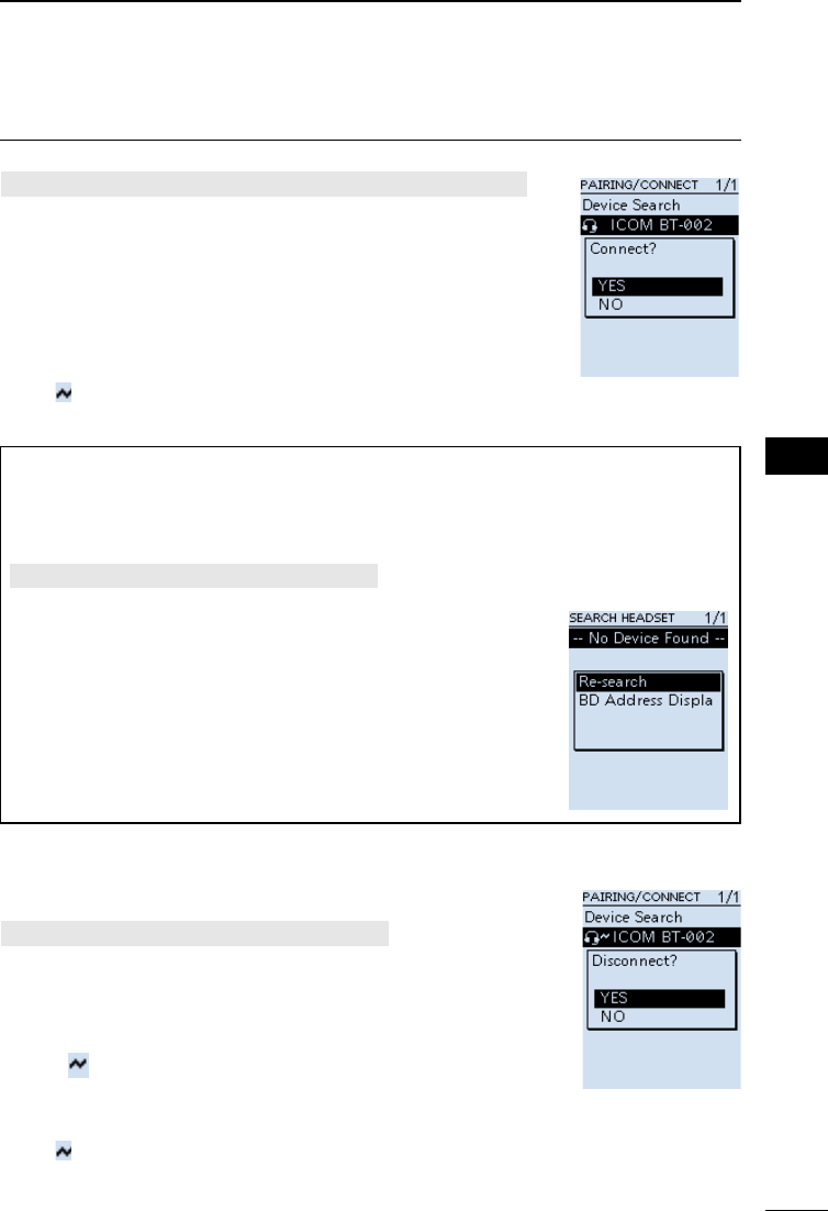
44
8
OTHER FUNCTIONS 8
201802 201802
BASIC MANUAL
3. Pairing and connecting a Bluetooth headset
[MENU] > Bluetooth Set > Pairing/Connect > Device Search
1. Push [MENU].
2. Select “Device Search” in the “Bluetooth Set” menu.
(Rotate [DIAL] to select it, and then push [ENTER].)
3. Select “Search Headset,” and then push [ENTER].
• The receiver starts searching for a headset.
4. Select a headset to pair, and then push [ENTER].
• A conrmation dialog is displayed.
5. Select “YES,” and then push [ENTER].
• “ ” is displayed if the headset is correctly connected.
LPush [CLEAR] to return to the Main screen.
TIP:
Auto Connect function
The receiver automatically connects to a paired Bluetooth device.
[MENU] > Bluetooth Set > Auto Connect
Re-searching Bluetooth device
“No Device Found” is displayed if the receiver could not
found a Bluetooth device.
1. Push [QUICK].
2. Select “Re-search.”
(Rotate [DIAL] to select it, and then push [ENTER].)
DDisconnecting a paired device
You can disconnect a paired Bluetooth device if it is not being used.
[MENU] > Bluetooth Set > Pairing/Connect
1. Push [MENU].
2. Select “Pairing/Connect” in the “Bluetooth Set” menu.
(Rotate [DIAL] to select it, and then push [ENTER].)
• Paired devices are displayed.
L“” is displayed, if the device is connected.
3. Select a device to disconnect, and then push [ENTER].
• A conrmation dialog is displayed.
4. Select “YES,” and then push [ENTER].
• “ ” disappears.
LPush [CLEAR] to return to the Main screen.
LTo re-connect a device, select the device on the Paring list again.

45
8OTHER FUNCTIONS
201802
BASIC MANUAL
■Using the Noise Blanker (NB)
The Noise blanker function eliminates pulse-type noise such as the noise from car
ignitions.
LThe function is usable in the LSB, USB, and CW modes.
[QUICK] > NB
■Using the Automatic Noise Limiter (ANL)
The Automatic Noise Limiter function reduces noise components while receiving.
LThe function is usable in the AM and AM-N modes.
[QUICK] > ANL
■Using the Automatic Frequency Control (AFC)
The Automatic Noise Limiter function reduces noise components while receiving.
LThe function is usable in the FM, FM-N, and WFM modes.
[QUICK] > AFC
■Using the Voice Squelch Control (VSC)
The Voice Squelch Control function opens the squelch, or stops a scan only when
voice components are detected in the signal. It is convenient to receive only voice
communications.
LThe function is usable in the FM, FM-N, WFM, AM, and AM-N modes.
[QUICK] > VSC
NOTE: The VSC function is designed to not detect a continuous audio signal. When
receiving a signal such as a radio broadcast program that contains a continuous audio
signal, the received audio may be broken up. In such case, turn OFF the VSC function.
■Operating Bluetooth®
DUnpairing a device
Before unpairing a connected headset or device, disconnect it.
[MENU] > Bluetooth Set > Pairing/Connect
1. Push [MENU].
2. Select “Pairing/Connect” in the “Bluetooth Set” menu.
(Rotate [DIAL] to select it, and then push [ENTER].)
• Paired devices are displayed.
3. Select a device to unpair, and then push [QUICK].
4. Select “Delete,” and then push [ENTER].
• A conrmation dialog is displayed.
5. Select “YES,” and then push [ENTER].
LPush [CLEAR] to return to the Main screen.
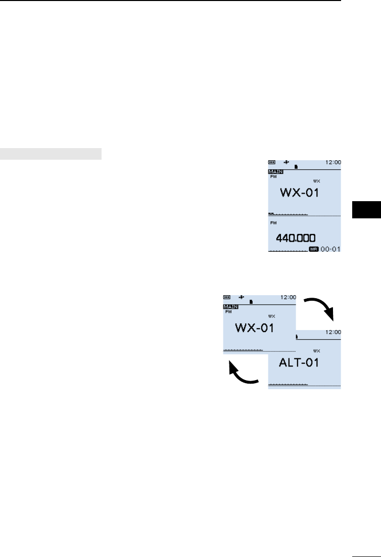
46
8
OTHER FUNCTIONS 8
201802 201802
BASIC MANUAL
■Using a Weather channel
(For only the USA version)
The receiver has 10 preset Weather channels. You can use these channels to monitor
broadcasts from the National Oceanographic and Atmospheric Administration (NOAA).
The receiver automatically detects a Weather alert tone on the selected Weather channel,
or while scanning.
DSelecting a Weather channel
[QUICK] > Weather CH
1. Push [QUICK].
2. Select “Weather CH.”
(Rotate [DIAL] to select it, and then push [ENTER].)
• A weather Channel is displayed.
3. Rotate [DIAL] to select a Weather channel.
LPush [SCAN] to start a Weather channel scan.
LPush [CLEAR] to return to the Main screen.
DReceiving a Weather Alert
NOAA broadcast stations transmit weather alert tones
before important weather announcements.
When the Weather Alert function is ON, the selected
weather channel is monitored every 5 seconds for an
announcement.
L When the alert is received, “WX” and “ALT”
alternately blink.
A WX Alert received on channel “01.”
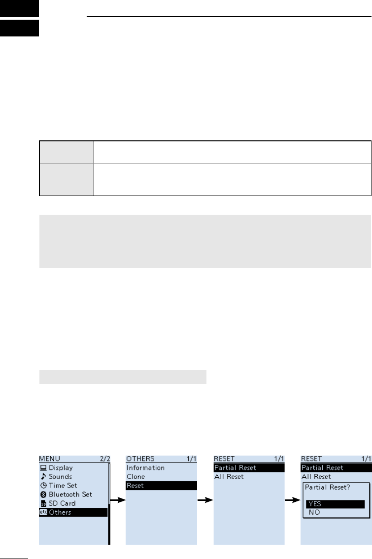
201802
47
BASIC MANUAL
9RESET/TROUBLESHOOTING
■Resetting
Occasionally, erroneous information may be displayed. This may be caused by static
electricity or by other factors.
If this problem occurs, turn OFF the receiver. After waiting a few seconds, turn ON the
receiver. If the problem still exists, perform a Partial reset, as described below.
If the problem still exists after a Partial reset, perform an All reset.
The resets affect the following:
Partial reset Settings on the MENU screen, receive history log, operating settings in
the VFO mode.
All reset
Settings on the MENU screen, receive history log, operating settings in
the VFO mode, Memory channel contents, Programmable Scan edges
and GPS memories.
NOTE:
An All reset clears all data and returns all settings to their factory defaults. Save memory
channel contents, setting status, and so on, onto an SD card before doing an All reset.
Refer to Section 7 of ADVANCED MANUAL for details.
LThe Bluetooth paring list is not cleared by an All reset.
DPartial reset
A Partial reset resets operating settings to their default values.
LThe following settings are not returned to their default values.
• Memory channels
• Programmable Scan edges
• GPS memories
[MENU] > Others > Reset > Partial Reset
1. Push [MENU].
2. Select “Partial Reset” in the “Others” menu.
(Rotate [DIAL] to select it, and then push [ENTER].)
• The conrmation dialog is displayed.
3. Select “YES,” then push [ENTER].
• After resetting, the IC-R30 will automatically restart.

48
9
RESET/TROUBLESHOOTING 9
201802 201802
BASIC MANUAL
■Troubleshooting
The following chart is designed to help you correct problems that are not equipment
malfunctions. If you are unable to locate the cause of a problem, or solve it through the
use of this chart, contact your nearest Icom Dealer or Service Center.
PROBLEM POSSIBLE CAUSE SOLUTION REF.
Receiver does
not turn ON.
• The battery pack/case is
exhausted.
• Bad connection of a battery pack/case.
• The battery polarity is reversed.
• Charge the battery pack, or
replace the batteries.
• Clean the battery terminals.
• Check the polarity in the case.
p. 2
–
–
No sound
comes from the
speaker.
• Volume level is too low.
• Earphone mode is ON.
• The squelch is set too tight.
• A Tone function (CTCSS, DTCS or
Digital Squelch (D.SQL)) is activated.
• An external speaker is connected
to the [SP] jack.
• A Bluetooth headset is connected.
• Push [▲] to increase the level.
• Set the “Earphone Mode” item
to “OFF” on the MENU screen.
• Set to the threshold level.
• Turn OFF the Tone function.
• Remove the external speaker.
• Disconnect the headset.
p. 4
–
p. 14
p. 15
–
p. 44
Sensitivity is too
low, and only
strong signals
are audible.
• The attenuator is activated.
• The RF gain is reduced.
( “RFG1” ~ “RFG9” is selected.)
• The coaxial cable is not
connected, or shorted. (When an
external antenna is used.)
• Turn OFF the attenuator.
• Set the “RF Gain” item to the
“RFG MAX” in the QUICK
menu window.
• Check the coaxial cable
connection or replace with a
new one.
p. 18
p. 18
–
Sensitivity is too
low on the BC
band (1 M).
• Internal antenna is not selected.
• Set the “Bar Antenna” item to
“Use” on the MENU screen.
–
Audio in the SSB
mode is unclear
or distorted.
• The incorrect sideband is selected. • Toggle between USB and LSB. p. 17
The function of
[DIAL] and [▲]/
[▼] is swapped.
• Functions assigned to [DIAL] and
[▲]/[▼] are swapped.
• Push [DIAL SEL] to switch the
functions.
p. 18
Frequency
cannot be set.
• The Key Lock function is ON.
• The Memory mode is selected.
• Turn OFF the Key Lock function.
• Push [VFO/MR] to select the
VFO mode.
p. 20
p. 16
The displayed
frequency is
erroneous.
• The CPU has malfunctioned.
• External factors have caused a
fault.
• Reset the receiver.
• Remove and reattach the
battery pack or case.
p. 47
p. 1
A Program
Scan does not
start.
• The Memory mode is selected.
• The same frequency has been
programmed in the scan edge channels
“FREQ HIGH” and “FREQ LOW.”
• Push [VFO/MR] to select the
VFO mode.
• Program different frequencies
in the scan edge channels.
p. 16
p. 33
A Memory Scan
does not start.
• The Memory mode is not selected.
• Only one or no memory channel
has been programmed.
• Push [VFO/MR] to select the
Memory mode.
• Program two or more memory
channels.
p. 16
p. 28
The Speech
function does
not work.
• Speech Level is set to “0” on the
“SPEECH” screen.
• Set the “SPEECH Level” item
to a higher level on the MENU
screen.
–

201802
49
BASIC MANUAL
10 SPECIFICATIONS
DGeneral
• Frequency coverage:
[A band]
USA-01 version 0.100000 ~ 821.999990 MHz
851.000000 ~ 866.999990 MHz
896.000000 ~ 3304.999990 MHz
USA-02 version 0.100000 ~ 3304.999990 MHz
EUR-01 version 0.100000 ~ 3304.999990 MHz
[B band]
USA-01 version 108.000000 ~ 520.000000 MHz
USA-02 version 108.000000 ~ 520.000000 MHz
EUR-01 version 108.000000 ~ 520.000000 MHz
• Receive modes:
Aband(≤1300MHz) FM/FM-N/WFM*1/AM/AM-N/LSB/USB/CW/CW-R/
D-STAR(DV)/P25/dPMR/NXDN-VN/NXDN-N/DCR
A band (>1300MHz) FM/FM-N/WFM/AM/AM-N
Bband FM/FM-N/AM/AM-N/D-STAR(DV)/P25/dPMR/NXDN-
VN/NXDN-N/DCR
• Operatingtemperaturerange: –20°C~+60°C,–4°F~+140°F
• Frequencystability: Lessthan±2.5ppm(–20°C~+60°C,–4°F~+140°F)
• Frequencyresolution: 0.01,0.1,1,3.125,5,6.25,8.33*2,9*3,10,12.5,15,20,
25,30,50,100,125,200KHz
• Numberofmemorychannels: 2000(in100groups)
+400(Scanedges:100(50pairs),
AutoMemoryWrite:200,andScanSkip:100)
• NumberofGPSmemories: 300
• Powersupplyrequirement: 5.0VDC(±5%)(UsingthesuppliedUSBcable)
3.6VDC(Usingthesuppliedbatterypack)
4.5VDC(Usingthebatterycase)
• Antennaimpedance: 50ΩUnbalanced
• Dimensions(Projectionsnotincluded):
58(W)×143(H)×30.5(D)mm,
2.3(W)×5.6(H)×1.2(D)in
• Weight(approximate): 200g,7.1oz
(Theantennaandthebatterypacknotincluded)
DReceiver
• Receivesystem: TriplesuperheterodyneandDownconverter
(AbandexceptWFM)
Doublesuperheterodyne(BbandandWFM)
• Intermediatefrequencies:
Band 1st IF (MHz) 2nd (MHz) 3rd (MHz)
A band 266.65,266.7,266.75 58.0500(exceptWFM)
10.7000(WFM)
0.4500(exceptWFM)
B band 46.3500 0.4500 –
LAllstatedspecicationsaretypicalandsubjecttochangewithoutnoticeorobligation.
*2ForonlyAIRband*3ForonlyBCband
*1“WFM”isnotselectable,dependingonthereceiverversionandreceivefrequency.

50
10
SPECIFICATIONS 10
201802 201802
BASIC MANUAL
• Sensitivityforallversions:
Mode Frequency range
(MHz)
Sensitivity
(μV)
Squelch Sensitivity
(μV)
SSB/CW
(10dBS/N)
0.495000 ~ 1.899990 0.4 –
1.900000 ~ 14.999990 0.25
15.000000 ~ 29.999990
50.000000 ~ 53.999990
144.000000~ 147.999990
430.000000 ~ 449.999990 0.32
AM
(10dBS/N)
0.495000 ~ 1.899990 2.2 2.2
1.900000 ~ 14.999990 1.4 1.4
15.000000 ~ 29.999990
118.000000 ~ 136.999990
FM
(12dBS/N)
(1kHz/±3.5
kHzDEV)
28.000000 ~ 221.999990 0.4 0.4
222.000000 ~ 832.999990 0.56 0.56
833.000000 ~ 1299.999990
1300.000000 ~ 1999.999990 1 1
2000.000000 ~ 2699.999990 1.8 1.8
2700.000000~3304.999990 10 10
WFM
(12dBS/N)
(1kHz/±52.5
kHzDEV)
76.000000~ 107.999990 1.8 5.6
D-STAR
(1%BER)
28.000000 ~ 29.999990 0.71 –
50.000000 ~ 53.999990
144.000000~ 147.999990
430.000000 ~ 449.999990 1
1260.000000 ~ 1299.999990
NXDN,dPMR,
DCR
(1%BER)
136.000000~ 173.999990 0.71 –
350.000000~ 379.999990 1
380.000000 ~ 511.999990
P25(5%BER)
136.000000~ 173.999990 0.4 –
400.000000 ~ 469.999990 0.56
763.000000~ 832.999990 0.71
833.000000 ~ 869.999990
• Selectivity:
SSB/CW Morethan1.8kHz/–6dB
AM/FM Morethan12kHz/–6dB,
Lessthan30kHz/–60dB(Lessthan1305MHz),
Lessthan30kHz/–40dB(1305MHzorhigher)
WFM Morethan150kHz/–6dB,
• Audiooutputpower(3.6V):
Externalspeaker Morethan0.2W(8Ωload,at10%distortion)
Internalspeaker Morethan0.4W(16Ωload,at10%distortion)
• Powerconsumption(3.6V,FM,SingleWatchmode,RecordingfunctionOFF,GPS
functionOFF,BacklightOFF):
Receiving 330 mA typical
Standby 200 mA typical
Powersaving 100mAtypical

51
BASIC MANUAL
MENU ITEMS
RX History
Digital Set
Tone Control
D-STAR
P25
dPMR
NXDN
DCR
Digital Monitor
RX Log
RX History Log
CSV Format
RX Record (D-STAR RPT)
D-STAR EMR AF Level
Fast Unmute (NXDN)
SPEECH
D-STAR RX Call Sign SPEECH
DIAL SPEECH
MODE SPEECH
SPEECH Language
Alphabet
SPEECH Speed
SPEECH Level
Function
Auto Power OFF
Power Save
Monitor
Dial Speed-UP
Key Lock
Active Band
Bar Antenna
Earphone Antenna ( ~ 1.3 G)
CI-V
CI-V Address
CI-V Baud Rate
CI-V Transceive
CI-V USB/Bluetooth
→REMOTE Transceive Address
USB Connect
USB Serialport Function
Near Station
Scan
Pause Timer
Resume Timer
Temporary Skip Timer
Program Skip
Group Link
P-Scan Edge
Program Link
Auto MW SCAN Memory Clear
Manage Memory
RX Recorder
<<REC Start>>/<<REC Stop>>
Play Files
Recorder Set
RX REC Condition
File Split
REC Operation
Player Set
Skip Time
GPS
GPS Information
GPS Position
GPS Memory
GPS Alarm
Alarm Select
Alarm Area (Group)
Alarm Area (RX/Memory)
GPS Logger
GPS Logger
Record Interval
Record Sentence
<<GPS Logger Only>>
GPS Set
GPS Select
Power Save (Internal GPS)
Manual Position
Refer to ADVANCED MANUAL for each menu item’s details. You can download
ADVANCED MANUAL from the Icom website.
http://www.icom.co.jp/world/support/download/manual
LThe displayed menu items may differ, depending on the receiver’s version or presettings.
Ask your dealer for details.

52
1
7
4
10
15
18
2
8
13
5
11
16
3
9
14
6
12
17
BASIC MANUAL
1
7
4
10
15
18
2
8
13
5
11
16
3
9
14
6
12
17
MENU ITEMS
Display
Backlight
Backlight Timer
LCD Dimmer
LCD Contrast
RX Popup
P25 RX ID Display
Digital RX Backlight
Scroll Speed
Opening Message
Battery Level (Power ON)
Single Band Display
Display Unit
Display Language**
System Language
Sounds
Earphone Mode
Beep Level
Beep/Vol Level Link
A/B Vol Link
Key-Touch Beep
Home CH Beep
Scan Stop Beep
D-STAR Standby Beep
Sub Band Mute (Main RX)
Scope AF Output
Time Set
Date/Time
DATA
TIME
GPS Time Correct
UTC Offset
Bluetooth Set
Bluetooth
Auto Connect
Pairing/Connect
Device Search
Pairing List*
<<Pairing Reception>>
Headset Set
AF Output
Icom Headset
Data Device Set
Serialport Function
Bluetooth Device Information
Initialize Bluetooth Device
SD Card
Load Setting
Save Setting
Import/Export
Import
Export
CSV Format
SD Card Info
Firmware Update
Format
Unmount
Others
Information
Battery Level
Version
Clone
Clone Mode
Reset
Partial Reset
All Reset
*Paired devices are displayed.
** Displayed only when “Japanese” is set to
the “System Language” item.

INDEX
53
BASIC MANUAL
A
About the microSD card ���������������������� 23
Accessories ������������������������������������������� x
Antenna ������������������������������������������������� 1
Attenuator �������������������������������������������� 18
Audio level ��������������������������������������������� 4
Automatic Frequency Control (AFC) ��� 45
Automatic Noise Limiter (ANL) ������������ 45
Auto Memory Write scan ��������������������� 32
B
Band Scope function ��������������������������� 21
Battery and charging cautions ��������������� v
Battery pack
Attaching ������������������������������������������� 1
Capacity of the battery pack ������������� 2
Charging ������������������������������������������� 2
Belt clip �������������������������������������������������� 1
Bluetooth® �������������������������������������������� 43
Disconnecting a paired device �������� 44
Pairing with a device ����������������������� 43
Unpairing a device �������������������������� 45
C
Charging ������������������������������������������������ 2
Charging with a USB cable�������������������� 3
Cleaning �����������������������������������������������vii
D
Decryption function ������������������������������ 10
Default setting�������������������������������������� 12
Descrambler function��������������������������� 10
DIAL/VOL Switch function ������������������� 18
Disposal ����������������������������������������������� viii
DTCS codes ���������������������������������������� 29
Dualwatch function ������������������������������ 19
E
Entering a frequency ��������������������������� 15
Explicit denitions ����������������������������������� i
F
FCC Information �������������������������������������ii
Features ������������������������������������������������� i
Formatting the microSD card����������������� 5
Frequency Selecting mode ������������������ 15
Front panel �������������������������������������������� 7
Function display������������������������������������� 9
G
GPS ����������������������������������������������������� 40
About the GPS POSITION screen �� 41
Displaying Position Data ����������������� 41
GPS Logger function ��������������������������� 42
About the log le ����������������������������� 42
Turning OFF the GPS Logger ��������� 42
H
Hand strap ��������������������������������������������� 1
K
Key Lock function �������������������������������� 20
Keypad �������������������������������������������������� 8
M
Memory channel
Selecting ����������������������������������������� 27
Writing ��������������������������������������������� 28
Viewing the memory contents ��������� 27
Memory mode�������������������������������������� 16
MENU
MENU screen �����������������������������������11
MENU items ������������������������������������ 47
Operation �����������������������������������������11
Selecting an item ���������������������������� 12
microSD card ��������������������������������������� 23
Formatting ����������������������������������������� 5
Inserting �������������������������������������������� 4
Removing ���������������������������������������� 26
Mode Speech �������������������������������������� 14
Monitor function ����������������������������������� 14

INDEX
54
1
7
4
10
15
18
2
8
13
5
11
16
3
9
14
6
12
17
BASIC MANUAL
N
Noise Blanker (NB) ������������������������������ 45
O
Opening Message ��������������������������������� 4
Operating theory �����������������������������������vii
P
Playback screen ���������������������������������� 25
PRECAUTIONS �������������������������������������iv
Priority watch ��������������������������������������� 38
Program scan �������������������������������������� 33
Program Link scan������������������������������� 34
Q
Quick Menu window ���������������������������� 13
R
Receiving
Receive band ���������������������������������� 17
Receive frequency �������������������������� 15
Receive mode ��������������������������������� 17
Recommendation �������������������������������� viii
Recording �������������������������������������������� 24
Playing back ������������������������������������ 25
Recording setting ���������������������������� 24
Starting recording ���������������������������� 24
Stopping recording �������������������������� 24
VOICE PLAYER screen ������������������ 25
Resetting ��������������������������������������������� 47
Partial reset ������������������������������������ 47
S
Scan ���������������������������������������������������� 29
Memory scan ���������������������������������� 29
Pause timer ������������������������������������� 30
Priority Watch function �������������������� 35
Program Skip scan �������������������������� 35
Resume timer ���������������������������������� 30
Skip frequencies ����������������������������� 35
Starting or canceling the scan ��������� 31
Temporary Skip function ����������������� 35
VFO scan ���������������������������������������� 29
Scan Types
All scan (ALL) ���������������������������������� 36
Auto memory write scan (Auto MW)�� 32
Band scan (BAND) �������������������������� 32
Group Link scan (GROUP LINK) ���� 36
Group scan (GROUP 00 ~ 99) �������� 36
Memory scan ���������������������������� 29, 36
Mode scan (MODE) ������������������������ 36
Near Station scan (Near Station) ���� 36
Program scan (P00 ~ P49) ������������� 32
Program Link scan (P-LINK 0 ~ 9) �� 32
VFO Scan ��������������������������������� 29, 32
SD card������������������������������������������������ 23
Formatting ����������������������������������������� 5
Inserting �������������������������������������������� 4
Removing ���������������������������������������� 26
Saving a setting data ������������������������ 5
Setting
Frequency ��������������������������������������� 15
Group Link �������������������������������������� 37
Skip channel ����������������������������������� 37
Skip, Temporary ���������������������������������� 35
Specications �������������������������������������� 49
Speech function ����������������������������������� 14
Squelch������������������������������������������������ 14
Sweep function ������������������������������������ 22
T
Temporary
Skip ������������������������������������������������� 35
Tone scan �������������������������������������������� 29
Troubleshooting ����������������������������������� 48
Tuning step ������������������������������������������ 16
Turning ON �������������������������������������������� 4
U
Unmount (microSD card) ��������������������� 26
V
VFO mode ������������������������������������������� 16
Voice Squelch Control (VSC) �������������� 45
W
Weather channel ��������������������������������� 46
Writing
Memory channel ����������������������������� 28

1-1-32 Kamiminami, Hirano-ku,
Osaka 547-0003, Japan
A7447D-1EX
Printed in Japan
© 2018 Icom Inc.