ICOM orporated 381801 381801-01 User Manual
ICOM Incorporated 381801-01
UserManual.wiki
>
ICOM orporated
>
381801 User Manual
User Manual
Navigation menu
Upload a User Manual
Namespaces
Wiki Guide
HTML
PDF
Info
Views
User Manual
Discussion / Help
Navigation
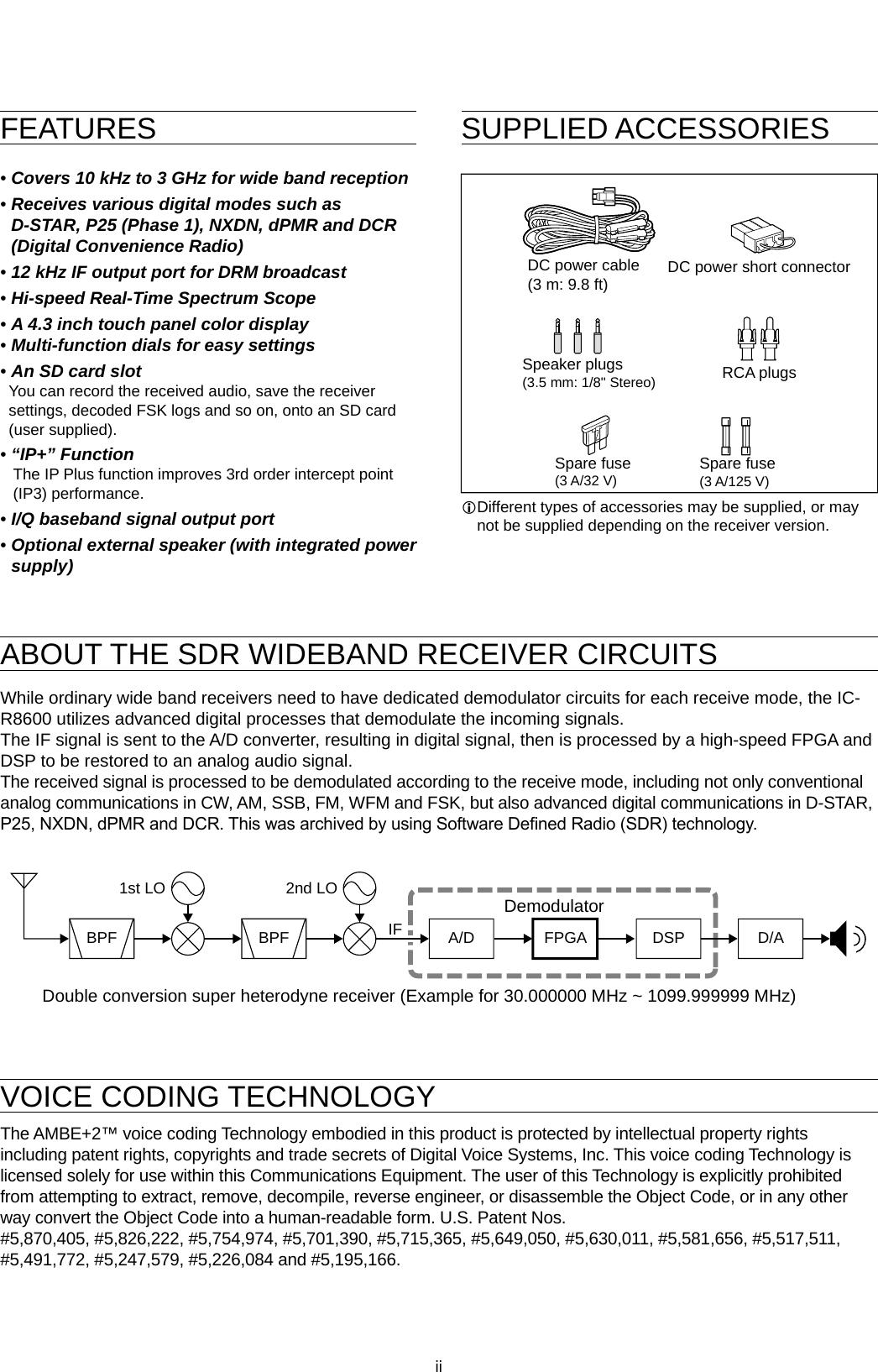
![iv DAbout the touch operationIn the manual, the touch operation is described as shown below.TouchIf the display is touched briey, one short beep sounds.Touch for 1 secondIf the display is touched for 1 second, one short and one long beep sound. DTouch screen precautions • The touch screen may not properly work when the LCD protection lm or sheet is attached. • Touching the screen with your nger nails, sharp topped object and so on, or touching the screen hard may damage it. • Tablet PC’s operations such as ick, pinch in and pinch out cannot be performed on this touch screen. DTouch screen maintenance • If the touch screen becomes dusty or dirty, wipe it clean with a soft, dry cloth. • When you wipe the touch screen, be careful not to push it too hard or scratch it with your nger nails. Otherwise you may damage the screen.ABOUT THE INSTRUCTIONSInstruction exampleMENU » SET > Time Set > DateDetailed instruction1. Push MENU.Push • The MENU screen opens.2. Touch [SET].MENU screen • The SET screen opens.3. Rotate to select “Time Set,” and then push .4. Rotate to select “Date,” then push .SET screenThis manual is described in the following manner.“ ” (Quotation marks):Used to indicate icons, setting items, and screen titles displayed on the screen. The screen titles are also indicated in uppercase letters. (Example: FUNCTION screen)[ ] (brackets): Used to indicate keys.Routes to the set modes and setting screensRoutes to the Set mode, setting screen and the setting items are described in the following manner.DATE/TIME screenDATE screen5. Touch [+] or [–] to set the date.6. Touch [SET] to save the entry.](https://usermanual.wiki/ICOM-orporated/381801/User-Guide-3440284-Page-5.png)
![vi DDigital Code Squelch ................................... 5-9 DNetwork Access Code (NAC) ......................5-9 D Group Code (COM ID) and CC .................5-10 DRadio Access Number (RAN) ....................5-10 DUser Code (UC).........................................5-10Descrambler function .....................................5-10Decryption function ......................................... 5-10Receive history log ......................................... 5-11Screen Capture function ................................. 5-11 DCapturing a screen .................................... 5-11 DViewing the captured screen ..................... 5-116 RECORDING AND PLAYING BACK ...............6-1Recording .........................................................6-1 DQuick recording ...........................................6-1 DNormal recording ......................................... 6-1Playing back .....................................................6-1Operation while playing back ...........................6-2Playing back on a PC ....................................... 6-2Checking the le information ............................6-3Deleting a le ....................................................6-3Deleting a folder ...............................................6-4PLAYER SET screen ........................................6-4RECORDER SET screen .................................6-47 USING AN SD CARD .......................................7-1About the SD card ............................................ 7-1 DSD card’s folder contents ............................7-1Saving data onto the SD card ..........................7-1Inserting or removing the SD card .................... 7-1 DInserting.......................................................7-1 DRemoving (While the receiver is OFF) ........7-1 DRemoving (While the receiver is ON) ..........7-1Formatting an SD card .....................................7-2Saving in the old format .................................... 7-2Saving the setting data .....................................7-2Loading the data les .......................................7-3Deleting a data le ............................................7-3Checking SD card information .......................... 7-38 Memory channels ...........................................8-1Selecting channel group ...................................8-1 DSelecting with / ......................8-1 DSelecting on the [GROUP SELECT] screen ..8-1Selecting a memory channel ............................8-2 DSelecting with .................................8-2 DSelecting with ..........................8-2 DSelecting using the keypad .........................8-2Writing a memory channel ............................... 8-2Copying the Memory contents .......................... 8-3Inserting a blank channel .................................8-3Clearing a memory channel .............................8-3Entering a group/memory name .......................8-4 DEntering a group name ................................8-4 DEntering a memory name ............................8-4About the MEMORY screen .............................8-59 SCANS .............................................................9-1Scan types ........................................................9-1Basic scanning .................................................9-1 DVFO scan and Memory scan ....................... 9-1 DPriority scan.................................................9-1Adjusting the scan speed .................................9-1Setting the Scan Resume function ................... 9-2 DSetting the scan delay timer ........................9-2 DSetting the Scan Resume function ..............9-2Setting the priority interval ................................9-2Priority scan ...................................................... 9-2 DPriority scan operation.................................9-2 DMonitoring the Priority channel .................... 9-2Scan Setting screen .........................................9-3Programmed scan and Fine Programmed scan .....9-4 DProgrammed scan operation .......................9-4 DFine Programmed scan operation ...............9-4∂F scan ............................................................9-5 D∂F scan operation ....................................... 9-5 DFine ∂F scan operation ............................... 9-5Auto Memory Write scan ..................................9-6 DAuto Memory Write scan operation .............9-6Memory scan and Select Memory scan ...........9-7 DMemory scan operation ............................... 9-7 DSelect Memory scan operation .................... 9-7 DSetting Select Memory channels ................. 9-8 D Canceling the Select Memory channel settings .. 9-8Mode select memory scan ...............................9-9 DSetting the receive mode ............................9-9Setting the skip frequency ............................... 9-9 DSetting the skip frequency ...........................9-9 DCanceling the skip frequency ......................9-9Setting the Temporary Skip ............................9-10Skip channel for memory scan .......................9-10Voice Squelch Control function ...................... 9-11Tone scan operation ....................................... 9-1110 CLOCK AND TIMER ......................................10-1Setting the Time and Date .............................. 10-1 DSetting date ...............................................10-1 DSetting time ...............................................10-1NTP Time Server ............................................10-1 DExecute the time synchronization .............10-1 DSetting the NTP Server address ................10-1Timer ..............................................................10-2 DSetting the Sleep timer ..............................10-2 DSetting the Daily timer ...............................10-2Timer (continued) ...........................................10-3 DTimer setting items ....................................10-3 DAbout the Timer recording .........................10-3](https://usermanual.wiki/ICOM-orporated/381801/User-Guide-3440284-Page-7.png)
![viiiPRECAUTIONSR DANGER! NEVER operate the receiver near unshielded electrical blasting caps or in an explosive atmosphere. This could cause an explosion and death.R WARNING! NEVER operate the receiver with a headset or other audio accessories at high volume levels. If you experience a ringing in your ears, reduce the volume or discontinue use.R WARNING! NEVER apply AC power to the [DC13.8V] socket on the receiver rear panel. This could cause a re or damage the receiver.R WARNING! NEVER apply more than 16 V DC to the [DC13.8V] socket on the receiver rear panel. This could cause a re or damage the receiver.R WARNING! NEVER reverse the DC power cable polarity. This could cause a re or damage the receiver.R WARNING! NEVER remove the fuse holder on the DC power cable. Excessive current caused by a short could cause a re or damage the receiver.R WARNING! NEVER let metal, wire or other objects contact the inside of the receiver, or make incorrect contact with connectors on the rear panel. This could cause an electric shock or damage the receiver.R WARNING! NEVER operate or touch the receiver with wet hands. This could cause an electric shock or damage to the receiver.R WARNING! Immediately turn OFF the receiver power and remove the power cable from the receiver if it emits an abnormal odor, sound or smoke. Contact your Icom dealer or distributor for advice.R WARNING! NEVER put the receiver on an unstable place where the receiver may suddenly move or fall. This could cause an injury or damage the receiver.R WARNING! NEVER operate the receiver during a lightning storm. It may result in an electric shock, cause a re or damage the receiver. Always disconnect the power source and antenna before a storm.CAUTION: NEVER expose the receiver to rain, snow or any liquids.CAUTION: NEVER change the internal settings of the receiver. This could reduce receiver performance and/or damage to the receiver. The receiver warranty does not cover any problems caused by unauthorized internal adjustments.CAUTION: NEVER install or place the receiver in a place without adequate ventilation.CAUTION: NEVER use harsh solvents such as Benzine or alcohol when cleaning, as they will damage the receiver surfaces.CAUTION: NEVER leave the receiver in areas with temperatures below –10°C (+14°F) or above +60°C (+140°F).CAUTION: NEVER place the receiver in excessively dusty environments. This could damage the receiver.DO NOT place the receiver against walls or put anything on top of the receiver. This may overheat the receiver.BE CAREFUL! The receiver will become hot when operating the receiver continuously for long periods of time.NEVER leave the receiver in an insecure place to avoid use by unauthorized persons.Turn OFF the receiver’s power and/or disconnect the DC power cable when you will not use the receiver for long period of time.The display may have cosmetic imperfections that appear as small dark or light spots. This is not a malfunction or defect, but a normal characteristic of LCDs.The IC-R8600 may receive its own oscillated frequency, resulting in no reception or only noise reception including on the Spectrum Scope screen, on some frequencies.](https://usermanual.wiki/ICOM-orporated/381801/User-Guide-3440284-Page-9.png)
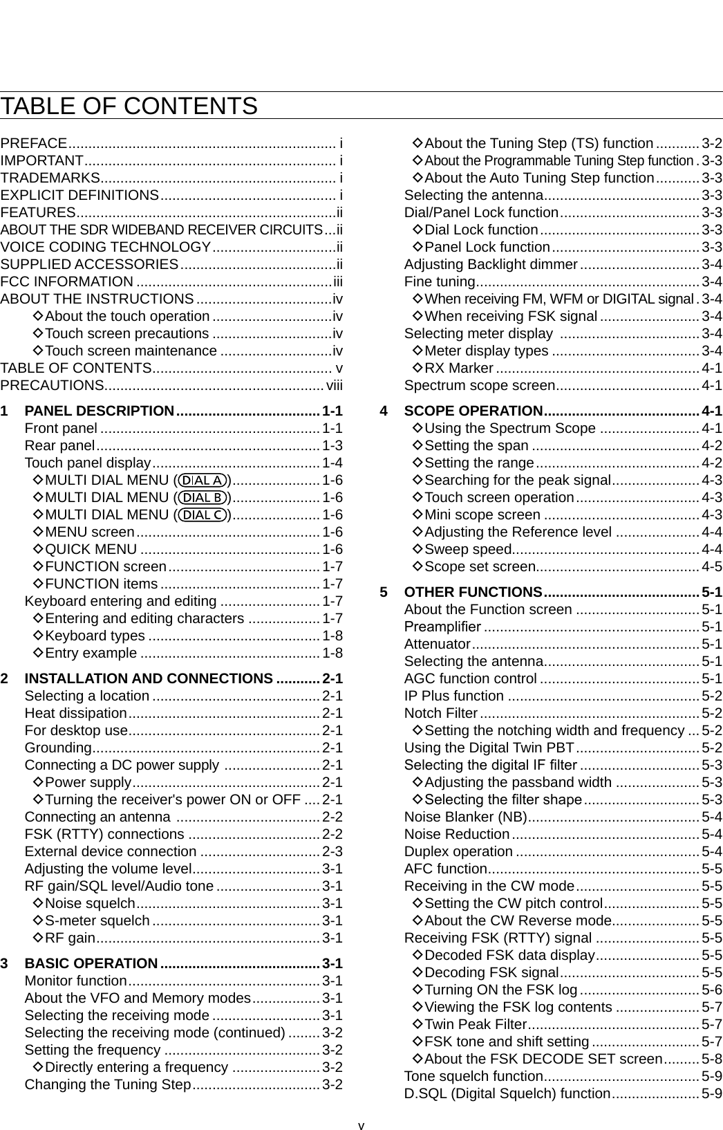
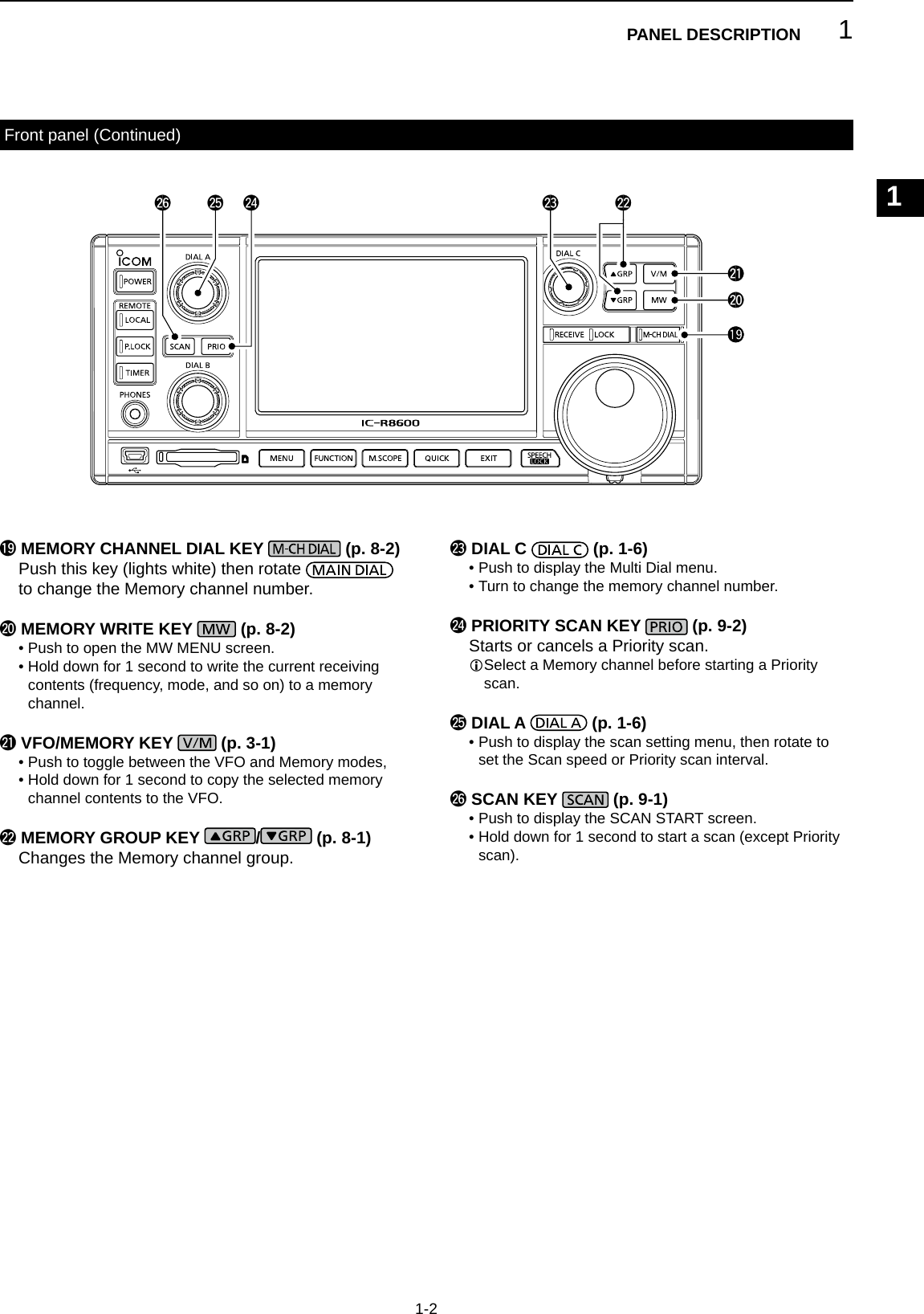
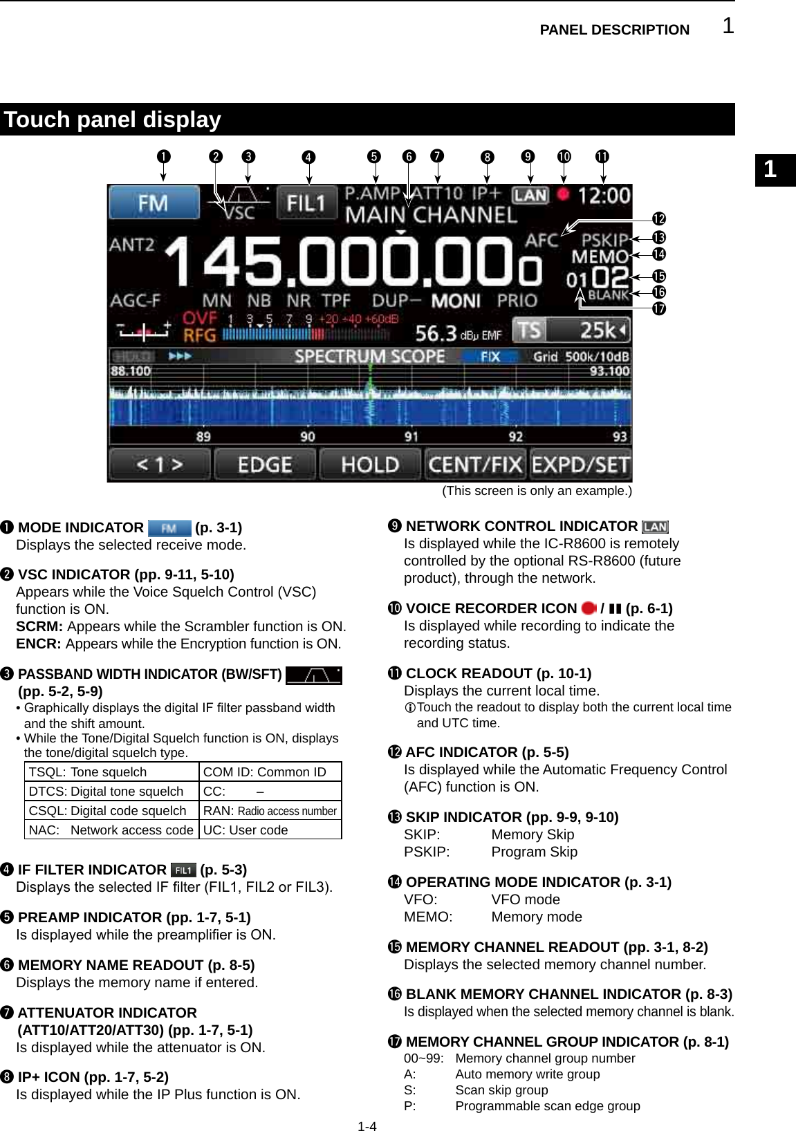
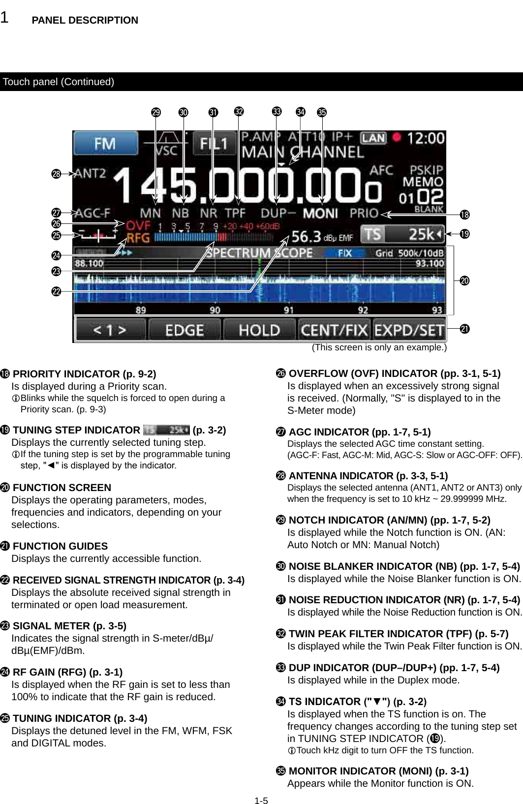
![1PANEL DESCRIPTION1-11-1Front panelq POWER KEY (p. 2-1) Turns the receiver ON (lights blue) or OFF.w LOCAL KEY (p. 16-2) Turns OFF the Remote mode.L In the Remote mode, all the operations on the panel except , and are locked.e PANEL LOCK KEY (p. 3-3) Locks the controls (lights white) on the front panel.L Hold down for 1 second to turn OFF the display.r TIMER KEY (p. 10-2) Turns ON (lights orange) or OFF the Timer function.L Set the current time to use the Timer function. (p. 10-1)t HEADPHONE JACK [PHONES] (p. 16-2) Accepts headphones. (3.5 mm: 1/8 in (d))y [USB] (mini-B type) PORT (pp. 2-3, 16-1) Connects to a PC. • Outputs the decoded FSK (RTTY) or D-STAR data. • Outputs the demodulated AF signal or 12 kHz IF signal. • Interface for the optional CS-R8600 or RS-R8600 (future product). • Interface for the remote control by the CI-V command.u DIAL B (p. 1-6) • Rotate to adjust the audio output level. • Push to display the setting menu, then rotate to adjust the RF gain (sensitivity), squelch threshold levels or audio tone (Treble or Bass). • Hold down to turn ON the Monitor function (the squelch opens).i SD CARD SLOT [SD CARD] (pp. 7-1, 7-2) Accepts an SD card.o MENU KEY (pp. 1-6, 11-1) Opens the MENU screens where you can modify the receiver settings and edit memory channels.!0 FUNCTION KEY FUNCTION (pp. 1-7, 5-1) Displays the FUNCTION screen where you can congure various settings.!1 MINI SCOPE KEY M.SCOPE (p. 4-3) • Push to display the Mini Scope. • Hold down for 1 second to display the Spectrum Scope.!2 QUICK KEY QUICK (p. 1-6) Displays the QUICK MENU.!3 EXIT KEY EXIT Exits a setting screen or returns to the previous screen.!4 SPEECH/LOCK KEY (p. 3-3) • Push to announce the receiving frequency and mode. • Hold down for 1 second to lock (lights white) .!5 TENSION ADJUSTER Adjusts the friction of in 3 steps.!6 MAIN DIAL Changes the operating frequency or setting value.!7 RECEIVE INDICATOR Lights green while receiving a signal or the squelch (p. 3-1) is opened.!8 LOCK INDICATOR (p. 3-3) Lights white while the is locked by .This section describes the keys, controls and dials that you use to operate the IC-R8600.Refer to the pages posted beside each key, control, or dial for details.qwertyu i o !0 !1 !2 !3 !4 !5!6!7!8](https://usermanual.wiki/ICOM-orporated/381801/User-Guide-3440284-Page-10.png)
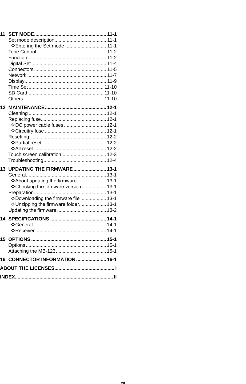
![1PANEL DESCRIPTION1-3Rear panelq DC POWER SOCKET [DC 13.8 V] (pp. 2-1, 16-2) Connects to the supplied DC power cable.w DC INPUT JACK [DC IN] (pp. 2-1, 16-2) Connects to the optional SP-39AD (External speaker with built-in power adapter) or AD-55NS (Power adapter).L Before connecting an SP-39AD or AD-55NS, connect the supplied DC power short connector to [DC 13.8V] (q).e GROUND TERMINAL [GND] (p. 2-1) Connects to ground to prevent electrical shocks and other problems.r ANTENNA CONNECTOR [ANT1] (N type) (p. 2-2) Connects to a 10 kHz ~ 3000 MHz antenna.t ANTENNA CONNECTOR [ANT2] (SO-239) (p. 2-2) Connects to a 10 kHz ~ 30 MHz antenna.y ANTENNA CONNECTOR [ANT3] (RCA) (p. 2-2) Connects to a 10 kHz ~ 30 MHz antenna.u AUX JACK [AUX] A reserved jack. No internal connection.i EXTERNAL METER JACK [METER] (pp. 2-3, 16-1) Connects to an external analog RSSI or squelch level meter (user supplied).o REFERENCE SIGNAL INPUT/OUTPUT CONNECTOR [REF I/O 10MHz] (BNC) (p. 16-1) Inputs or outputs a 10 MHz reference frequency signal.!0 IF SIGNAL OUTPUT CONNECTOR [10.7MHz OUT] (BNC) (p. 16-1) Outputs a 10.7 MHz IF signal.!1 I/Q DATA OUTPUT PORT [I/Q OUT] (pp. 2-3, 16-1) Outputs I/Q data.LConnect a USB (1.1/2.0 standard) port (B type).!2 EXTERNAL SPEAKER JACK [EXT-SP] (pp. 2-3, 16-2) Connects to an optional external speaker SP-39AD (External speaker with built-in power adapter). (3.5 mm: 1/8 in (d))LAccepts a 4~8 Ω speaker.!3 AF/IF OUTPUT JACK [AF/IF] (pp. 2-3, 16-1) Outputs the demodulated AF signal, or a 12 kHz IF signal.LThe output level is set, regardless of the volume control.!4 REMOTE CONTROL JACK [REMOTE] (pp. 2-3, 16-2) Connects to a PC for remote control using CI-V commands. (3.5 mm: 1/8 in (d))!5 [USB] (B type) PORT (p. 2-3, 16-1) Connects to a PC. • Outputs the decoded FSK (RTTY) or D-STAR data. • Outputs the demodulated AF signal or 12 kHz IF signal. • Interface for the optional CS-R8600 or RS-R8600 (future product). • Interface for the remote control by the CI-V commands.!6 [MUTE] JACK/[MUTE] SWITCH (pp. 2-3, 16-1) Used for the Mute function, or Bit Error Rate (BER) Measurement function. (3.5 mm: 1/8 in (d))L Slide the switch to the left when you use the Mute function. The IC-R8600's receive circuitry is deactivated by the input voltage.L Slide the switch to the right when you use the BER Measurement function.!7 LAN PORT [LAN] (pp. 2-3, 16-1) Connects to a network to use the functions shown below. • Automatic time synchronization. • Outputs the received signal in demodulated AF signal, or in 12 kHz IF signal, through the network. • Remotely controlling using the optional RS-R8600 (future product).o!0wit r eyu!7!1 !3!2 !4 !5 q!6](https://usermanual.wiki/ICOM-orporated/381801/User-Guide-3440284-Page-12.png)
![1PANEL DESCRIPTION1234567891011121314151617181920211-6Touch panel (Continued) z Push to open the Multi Dial menu. Push again to close the menu. z While the Multi Dial menu is opened, touch the desired item and rotate to set the desired value or function. DMENU screen z Push to open the MENU screen.L The menu items differ, depending on the selected receive mode. DMULTI DIAL MENU ( ) DMULTI DIAL MENU ( ) DMULTI DIAL MENU ( ) • When rotating . • When rotating . • When pushing .LTouch to select an item, then rotate . • When pushing .LTouch to select an item, then rotate . • When holding down for 1 second.LTouch an item. • When holding down for 1 second. • The Monitor function is turned ON ([RECEIVE] lights green).LRelease to turn OFF the Monitor function. DQUICK MENU z Push to open the QUICK MENU.L The items differ, depending on the operating condition.QUICK MENU exampleTouch the key to turn ON and OFFMulti dial menu itemsDisplayed items differ, according to the selected receive mode.FM/WFM AM/S-AM SSB CWAFC*1 PBT1 PBT1 PBT1PBT2 PBT2 PBT2VSC*1 VSC*1 VSC*1 CW PITCHBACKLIGHT BACKLIGHT BACKLIGHT BACKLIGHTFSK DIGITAL NB*2NR*2PBT1 AFC*1 LEVEL LEVELPBT2 DEPTHTPF*1 WIDTHBACKLIGHT BACKLIGHTNOTCH*2POSITIONWIDTH*1*1 Touch to turn the function ON or OFF.*2 Displayed when you touch the item on the FUNCTION screen for 1 second.](https://usermanual.wiki/ICOM-orporated/381801/User-Guide-3440284-Page-15.png)
![1PANEL DESCRIPTION1-7Touch panel (Continued) DFUNCTION screen z Push FUNCTION to open the FUNCTION screen.LTo close the FUNCTION screen, push EXIT.Function nameSelected optionLights blue in use DFUNCTION items zTouch an item to change its setting.*1 Touch for 1 second to open its function menu.*2 Touch to open its function menu.FUNCTION OPTIONANT ANT1, ANT2 or ANT3P.AMP OFF or ONATT OFF, 10dB, 20dB or 30dBIP+ OFF or ONTONE*1OFF, TSQL or DTCSTONE/SHIFT*2FSK RX Frequency, FSK Tone Frequency or FSK Shift widthD.SQL*1D-STAR: OFF or CSQLP25: OFF or NACdPMR: OFF, COM ID or CCNXDN: OFF or RANDCR: OFF or UCAGC*1FAST, MID or SLOWNOTCH*1OFF, AN or MNNB*1OFF or ONSCRAM*1OFF or ONENCRYP*1OFF or ONNR*1OFF or ONDUP*1OFF, DUP– or DUP+Category Edit itemsTotal character numberSelectable charactersMEMORYGROUP NAMEMEMORY NAME 16A to Z, a to z, 0 to 9, (space), @ % & # + - = [ ] / ( ) : ; ˄ ! ? < > . , DISPLAY OPENING COMMENT 10A to Z, 0~9, (space), / @ - .SD cardFILE NAME*15A to Z, a to z, 0 to 9, (space), @ % & # + - = [ ] / ( ) : ; ^ ! ? < > , . " $ ' * \ _ ` { } | ~TIME NTP SERVER ADDRESS 64A to Z, a to z, 0~9, (space), - .NETWORKNETWORK NAME15A to Z, 0 to 9, (space), ! " # $ % & ( ) + , - . ; = @ [ ] ^ _ ' { } ~NETWORK RADIO NAME16A to Z, a to z, 0 to 9, (space), ! " # $ % & ' ( ) * + , - . / : ; < > = ? @ [ ] ^ _ ` { } | ~NETWORK USER1 IDNETWORK USER2 ID16A to Z, a to z, 0 to 9, (space), ! " # $ % & ' ( ) * + , - . / : ; < > = ? @ [ ] ^ _ ` { } | ~NETWORK USER1 PASSWORDNETWORK USER2 PASSWORD16A to Z, a to z, 0 to 9, (space), ! " # $ % & ' ( ) * + , - . / : ; < > = ? @ [ ] ^ _ ` { } | ~*Illegal characters " / : ; * < > "Keyboard entering and editing DEntering and editing charactersYou can enter and edit characters in the items in the following table.](https://usermanual.wiki/ICOM-orporated/381801/User-Guide-3440284-Page-16.png)
![1PANEL DESCRIPTION1234567891011121314151617181920211-8 DEntry exampleExample: Entering memory name "MAIN CHANNEL."1. Open the MEMORY screen.MENU » MEMORY2. Rotate to select the channel you want to enter a name in. 3. Push .4. Touch “Edit Name.”5. Touch for 1 second to select the upper case entry mode.6. Enter a name of up to 16 characters, then touch [ENT]. • The entered name is displayed. DKeyboard typesYou can select the Full Keyboard or Tenkey in “Keyboard Type” in the QUICK MENU.1. When the keypad is opened, push .2. Touch to select the keyboard type.MENU » SET > Function > Keyboard TypeInformationL You can also select the Keyboard type in the Set mode. Keyboard entering and editing (Continued)Enters a spaceCursorMoves the cursor forwardSwitched to Full Keyboard Switched to Tenkey](https://usermanual.wiki/ICOM-orporated/381801/User-Guide-3440284-Page-17.png)
![2INSTALLATION AND CONNECTIONS2-12-1Selecting a locationFor desktop useSelect a location for the receiver that allows adequate air circulation, free from extreme heat, cold or vibrations, and other electromagnetic sources.An improper location may damage the receiver.Never place the receiver in areas such as:• Temperatures below –10°C (+40°F) or above +60°C (+140°F).• Unstable place slope or vibrate.• In direct sunlight.• High humidity and temperature.• Dusty environments.• Noisy environments. DPower supplyYou can use any of the power sources listed below. • 13.8 V DC power supply (User supplied) • Optional SP-39AD (External speaker with built-in power supply) • Optional AD-55NS (Power adapter) DTurning the receiver's power ON or OFF zPush to turn ON the power. z Hold down until the "POWER OFF..." is displayed.The receiver has a stand for desktop use. zPull the stand until it locks in place.CAUTION: NEVER carry the receiver by holding the stand, dials, controls and so on. This may damage them.Heat dissipationGroundingTo prevent electrical shock, interfere from other electric devices and other problems, ground the receiver using the ground terminal [GND] on the rear panel.For best results, connect a heavy gauge wire or strap to a long ground rod. Make the distance between the [GND] terminal and ground as short as possible.RWARNING! NEVER connect the [GND] terminal to a gas or electric pipe, since the connection could cause an explosion or electric shock. • DO NOT place the receiver against walls, or put anything on top of the receiver. This may block airow. • NEVER install the receiver in a place without adequate ventilation. Heat dissipation may be reduced, and the receiver may be damaged.StandConnecting a DC power supply +_IC-R8600AC outletWhen disconnecting,rmly push down the locking tab and then pull the connector out of the socket.AC outletShort connector:Connect whenSP-39AD orAD-55NS is used.AC outlet DC power cableAD-55NS (Option)SP-39AD(Option)SpeakercableSupplied DC power cableRedExternal power supply(User supplied)Black](https://usermanual.wiki/ICOM-orporated/381801/User-Guide-3440284-Page-18.png)
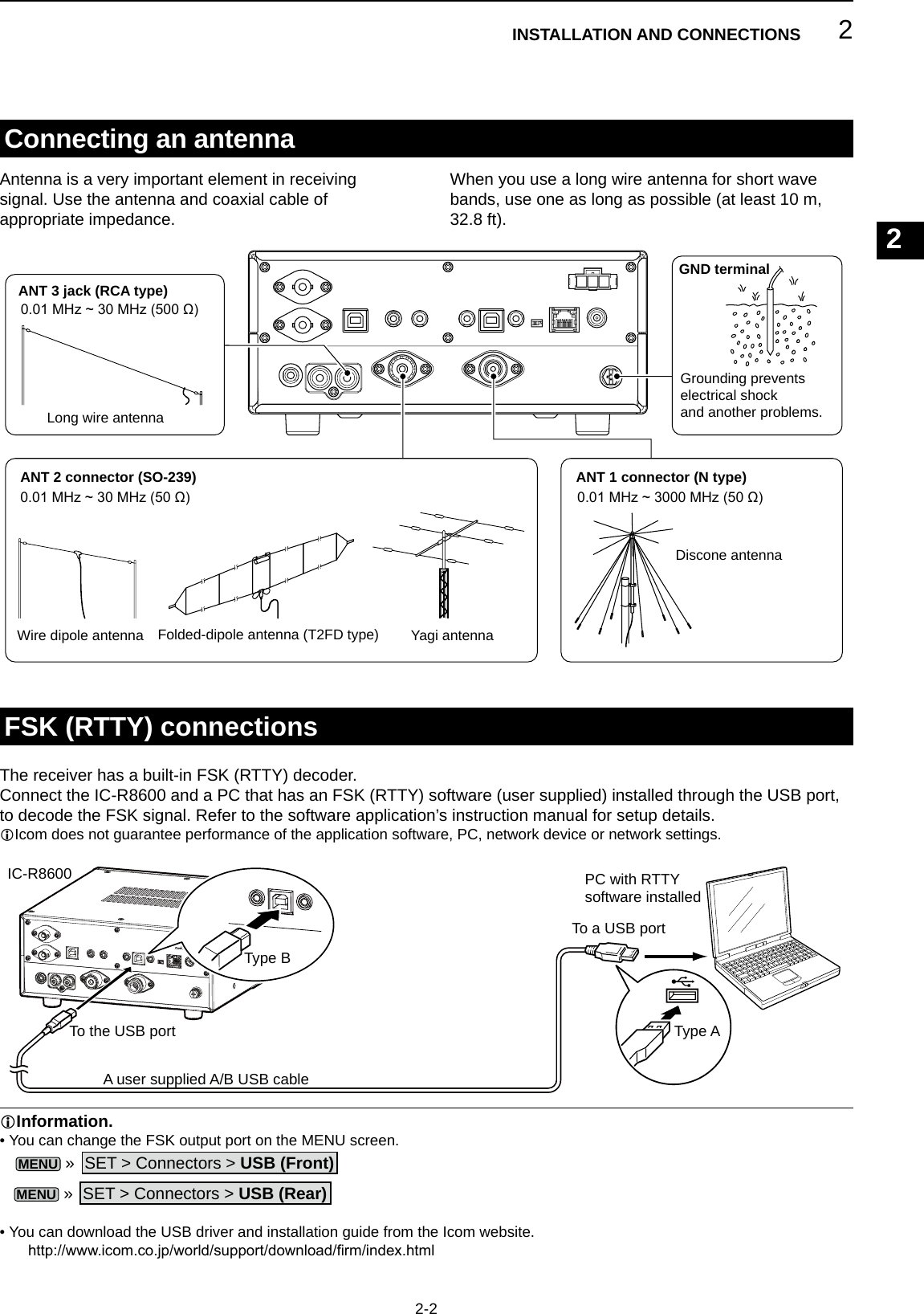
![2INSTALLATION AND CONNECTIONS2-3External device connection[DC 13.8 V] DC power connector(p. 16-2)[DC IN] jack (p. 16-2)[LAN] port (p. 16-1)[AF/IF] jack (3.5 mm: 1/8 in (d)) (p. 16-1)[METER] jack (p. 16-1)[I/Q OUT] port (USB B type) (p. 16-1)[MUTE] jack (3.5 mm: 1/8 in (d)) (p. 16-1)MUTE switch (p. 16-1)CAB-1258 (Supplied)OPC-1605 (Supplied)Connect when an SP-39AD or AD-55NS is used.Connects the optional SP-39AD or AD-55NS. Connects to a network to use the functions shown below. • Automatic time synchronization. • Outputs the demodulated audio signal or 12 kHz IF signal to the network. • Remote control using the optional RS-R8600 (future product).Outputs the demodulated audio signal or 12 kHz IF signal to the network.Outputs the voltage that represents the received signal strength or squelch levels to an external meter.Outputs the In phase/Quadrature (I/Q) data.Inputs the Mute control signal.Used for the Bit Error Rate (BER) measurement function.[REMOTE] jack (p. 16-2)(3.5 mm: 1/8 in (d))[EXT-SP] (External speaker) jack (p. 16-2) (3.5 mm: 1/8 in (d))Connects the optional SP-39AD or SP-23.[USB] port (p. 16-1)L Mini-B type on the front panel, B type on the rear panel. • Outputs the decoded FSK (RTTY) or D-STAR data to the PC. • Outputs the demodulated audio or 12 kHz IF signal to the PC.• Remote control operation using the optional RS-R8600 (future product). • Programing using the optional CS-R8600.Accepts headphones with 8 ~ 16 Ω impedance. • Outputs more than 50 mW into an 8 Ω load. • The volume level may differ, depending on the headphones.[PHONES] Headphones (p. 16-2)L Icom does not guarantee the performance of the PC, network device or network settings.Remotely controls the receiver, using the CI-V commands.L Refer to the Icom web site for the CI-V commands.http://www.icom.co.jp/world/support/download/Manual(3.5 mm: 1/8 in (d))](https://usermanual.wiki/ICOM-orporated/381801/User-Guide-3440284-Page-20.png)
![3BASIC OPERATION1234567891011121314151617181920213-13-1L The status or position of each key or dial is stored and recalled when the power is turned ON.Rotate to adjust the volume level. • While adjusting, the volume level is indicated in %.Adjusting the volume levelAbout the VFO and Memory modes zPush V/M to select the VFO or Memory mode.Selecting the receiving mode1. Touch the receiving mode icon. (Example: FM)Mode key Receiving mode[FM] FM[WFM] WFM[AM] AM ↔ S-AM(D)*[SSB/CW] USB* ↔ CW*[FSK] FSK*[DIGITAL] D-STAR→P25→dPMR→NXDN-vn→NXDN-n→DCR→D-STAR*Touch for 1 second to select other modes. See the table below.Mode key Receiving mode[AM]S-AM(D)→S-AM(U)→S-AM(L)→S-AM(D)[SSB/CW] CW ↔ CW-R, or USB ↔ LSB[FSK] FSK ↔ FSK-R2. Touch to select the receive mode. (Example: AM)L When the mode key is touched for 1 second, the selectable modes differ. See the table below. •Selectable modes when the mode key is touchedMODE screen •Selectable modes when the mode is touched for 1 secondRF gain/SQL level/Audio tone1. Push .2. Touch an item to select. (Example: RF GAIN)3. Rotate .•Settable range RF GAIN (Sensitivity): 0 ~ 100% SQL (Squelch): 0 ~ 100% TREBLE (Higher tone): –15 to +15 BASS (Lower tone): –15 to +15DNoise squelchThe Noise Squelch allows the audio to be heard only while receiving a signal that includes less noise than a set level. • Activates when the squelch level is set to between 30% and 50% in the FM, AM, S-AM or DIGITAL mode. • A higher level blocks weak signals. A lower level allows you to hear weak signals including noise.L While the squelch is closed, the noise audio is muted and the [RECEIVE] indicator is OFF.DS-meter squelchThe S-meter Squelch mutes the speaker sounds when the signal strength is less than the set value. • Activates when the squelch level is set to between 50% and 100% in any mode.•The squelch level is indicated by the position of “▼.”LWhen the received signal is stronger than the S-meter squelch level designated by the “▼,” the squelch opens.DRF gainNormally, set the RF gain to maximum (100%). • You can adjust the RF gain to decrease the interference or noise from a nearby strong station.• indicates that the RF gain is reduced.LIf a strong signal is received and (Overow) appears, reduce the RF gain until disappears.VFO mode You can set the receive frequency by rotating MAIN DIAL or by directly entering it with the keypad.Memory modeYou can set the receive frequency by selecting a preset channel. See Section 8 for details. z Hold down to forcibly open the squelch. • [MONI] appears and [RECEIVE] lights.L You can change the function in the digital mode setting on the MENU screen.MENU » SET > Digital Set > Digital MonitorMonitor functionVFO mode Memory modeGroup No. Channel No.V/MS-meter squelch levelInformationLWhen the squelch circuitry activates to emit the audio, "Squelch opens." When the squelch circuitry mutes the audio emission, "Squelch closes." L You can chose the receiving mode icons that appears when you touch the [DIGITAL] key.MENU » SET > Digital Set > Digital Mode Select](https://usermanual.wiki/ICOM-orporated/381801/User-Guide-3440284-Page-21.png)
![3BASIC OPERATION3-2Setting the frequency zRotate to set the receive frequency. • The displayed frequency changes depending on the selected tuning step. DDirectly entering a frequencyYou can set the frequency with the keypad.Example: Entering 383.000000 MHz1. Touch the MHz digits.2. Start entry with the MHz digits.LTo clear the entry, touch [CE].L To clear the entry and return to the previous screen, push EXIT.3. Touch [ENT] to set the entered frequency. • Closes the F-INP screen.L If you touch [ENT] when the digits under 100 kHz are not entered, “0” will be automatically entered into the blank digits.Entry examples • 14.025000 MHz: [1], [4], [•], [0], [2], [5], [ENT] • 21.240000 MHz: [2], [1], [•], [2], [4], [ENT] • 14 MHz: [1], [4], [ENT] • 150 kHz: [0], [•], [1], [5], [ENT] • Changing from 21.240000 MHz to 21.360000 MHz: [•], [3], [6], [ENT] (You can omit MHz digit entry.)Changing the Tuning StepSelecting the receiving mode (continued)1. Touch the TS indicator.2. Touch to select the tuning step. (Example: 20k) • The tuning step is set and returns to the previous screen.LnformationL • S (Synchronous)-AM mode:The Synchronous AM demodulation is a receive method that mixes the incoming signal with a pure carrier frequency with no level variation, then extracts one of the two sides (USB or LSB) signal which is free from interferences.This method is effective to reduce the distortions due to fading, or interferences from adjacent stations. •When the "D-STAR" and "FM" icons alternately blink:Indicates that an FM signal is being received while in the Digital (D-STAR) mode. DAbout the Tuning Step (TS) function By turning the Tuning Step function ON or OFF, you can change the frequency in MHz steps or 10 Hz.Changing the frequency in MHz steps: z Touch the MHz digit for 1 second, then rotate .Changing the frequency in 10 Hz steps: z Touch the kHz digit to turn OFF the TS function, then rotate .L To set the frequency in 1 Hz steps, directly enter the frequency with the keypad.The Tuning Step function is ON.The Tuning Step function is OFF.](https://usermanual.wiki/ICOM-orporated/381801/User-Guide-3440284-Page-22.png)
![3BASIC OPERATION1234567891011121314151617181920213-3Selecting the antenna D About the Programmable Tuning Step functionYou can preset the tuning step between 0.1 kHz and 999.9 kHz in 100 Hz steps.1. Touch the TS indicator.2. Touch (Programmable TS icon).The IC-R8600 has three antenna connectors: ANT1, ANT2, and ANT3. You can use either ANT1, ANT2, or ANT3 for receiving below 30 MHz.1. Rotate to set a frequency to below 30 MHz (10 kHz–29.999999 MHz). • The selected antenna connector indicator appears under the receiving mode icon.2. Touch the antenna connector indicator. • Each touch changes the selected antenna connector (ANT1, ANT2 and ANT3). L Next time you set the same frequency, the same antenna connector is automatically selected.Dial/Panel Lock function DDial Lock functionThe Dial Lock function electronically locks the dial to prevent frequency changes caused by accidently moving MAIN DIAL. z Hold down SPEECH for 1 second to turn the Dial Lock function ON or OFF. • The [LOCK] LED lights while the function is ON. • This function does not work when the MENU, FUNCTION, QUICK menu, Set mode or Scan Start screen is displayed.LYou can change this setting on the MENU screen.MENU » SET > Function > [SPEECH/LOCK] Switch DPanel Lock functionThe Panel Lock function locks all the controls on the front panel except and . z Push to turn the Panel Lock function ON or OFF.LP.LOCK indicator lights while the panel is locked. • Holding down for 1 second turns the Dial Lock function ON, and turns OFF the display. • The indicator lights while the function is ON. • This function does not work when the MENU, FUNCTION, QUICK menu, Set mode or Scan Start screen is displayed.LYou can set to lock only keys on the MENU screen.MENU » SET > Function > P.LOCK Key DAbout the Auto Tuning Step functionWhen you rapidly rotate , the tuning speed automatically accelerates.LYou can change this setting on the MENU screen.MENU » SET > Function > MAIN DIAL Auto TS3. Start entry with the kHz digits. (Example: 20.5 kHz)LTo clear the entry, touch [CE].LPush to chancel the entry.LYou can also enter by rotating .Changing the Tuning Step (Continued)4. Touch [ENT] to set the entered frequency. • Closes the Programmable TS screen.Entry examples • 14.2 kHz: [1], [4], [•], [2], [ENT] • 14.0 kHz: [1], [4], [ENT] • 150 kHz: [1], [5], [0], [ENT] • Change 14.2 kHz to 14.5 kHz: [•], [5], [ENT] (You can omit kHz digit entry.)長く押す白色に点灯Lights whiteHold down for 1 secondTS indicator](https://usermanual.wiki/ICOM-orporated/381801/User-Guide-3440284-Page-23.png)
![3BASIC OPERATION3-41. Push . • Opens the setting menu.2. Touch [BACKLIGHT]. • Settable range: 0 (dark) ~ 100% (bright)Adjusting Backlight dimmer3. Rotate to adjust the brightness.L You can reset to the default setting on the MENU screen.MENU » SET > Display > LCD BacklightSelecting meter display You can display one of the 4 different receive signal parameters. z Touch the meter to select the parameter you want to display.LYou can select the meter display also on the QUICK menu.Fine tuning DWhen receiving FM, WFM or DIGITAL signalYou can have a ne tuning into the signal by setting the marker on the tuning indicator to the center position.L In the WFM mode and when the AFC function is ON, the marker may not be steady in the center position. DWhen receiving FSK signalYou can have a ne tuning into the signal by tuning to where both “◄” and “►” are displayed in the tuning indicator.Tuning marker •S-meter: Received signal strengthRelative signal strength represented by S1 to S9. (in 6 dB steps)At S9, the input signal level is 50µV (34 dBµ).At S9 +20 dB, the input signal level is 54 dBµ. •dBµ meter: Absolute voltage (Terminated)0 dBµ is the level corresponding to 1 µV that is produced on a 50 Ω terminated load. •dBµ EMF meter: Absolute voltage (Opened)EMF (Electro Motive Force) is the unit of voltage produced at an opened terminal.LIndicated in 6 dB higher than a 50 Ω terminated load. •dBm meter: Absolute power0 dBm is the level corresponding to 1 mW that is produced at a 50 Ω terminated load. DMeter display types](https://usermanual.wiki/ICOM-orporated/381801/User-Guide-3440284-Page-24.png)
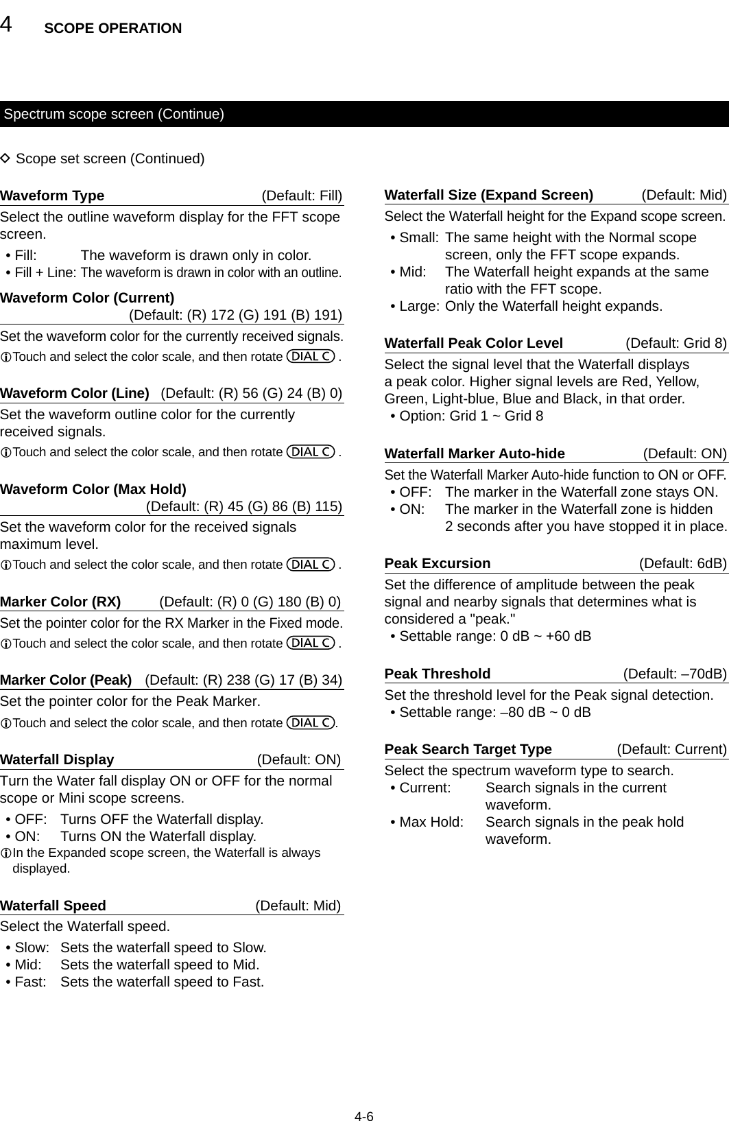
![4SCOPE OPERATION1234567891011121314151617181920214-14-1Spectrum scope screenThis spectrum scope enables you to display the activity on the selected frequency range, as well as the relative strengths of various signals.The IC-R8600 has two spectrum scope modes. One is the Center mode, and another one is the Fixed mode. You can also turn the Waterfall display ON or OFF.In addition, you can select a Mini scope screen to save screen space. DUsing the Spectrum Scope1. Open the SPECTRUM SCOPE screen.MENU » SCOPE• Center mode screenThe operating frequency is always displayed in the center of the screen.• Fixed mode screenThe activity on the selected frequency range can easily be observed using this mode.FFT scope zone(FFT: Fast Fourier Transform)FFT scope zoneSpan (Display range)Edge (Upper frequency)Span (Display range)Edge (Lower frequency)Waterfall zoneWaterfall zoneGrid (frequency/level)Grid (frequency/level)Center mode iconFixed mode iconDisplay frequency stays on CenterDisplay frequency movesSPECTRUM SCOPE screenFunction menu (Menu 2) zTouch <1> to switch to Menu 2. DRX MarkerIn the Fixed mode, the RX Marker always marks the receive frequency on the SPECTRUM SCOPE screen.L The marker marks the receive frequency even during peak hold. LThe RX Marker is not displayed in the Center mode.L When changing the frequency, the Waterfall maker is displayed on the Waterfall zone.RX Marker (green)2. To exit the SPECTRUM SCOPE screen, push EXIT. [Function menu keys]Key Action< 1 >< 2 >Toggles the Function menu between Menu 1 and Menu 2.SPANIn the Center mode, selects the scope span. • Selectable spans: ±2.5, 5.0, 10, 25, 50, 100, 250, 500 kHz, 1.0 MHz and 2.5 MHzEDGE In the Fixed mode, selects the Edge frequencies.HOLDTouchTurns the Peak Hold function ON or OFF.• “HOLD” and the Marker are displayed. Freezes the current spectrum.Touch for 1 secondClears the Peak Hold level display.CENT/FIX Selects the Center or Fixed mode.EXPD/SETTouch Selects the Expanded or Normal screen.Touch for 1 secondOpens the SCOPE SET screen.REFOpens the Reference level window.L Rotate to adjust the Reference level.L Touch again to close the window.SPEEDSelects the sweep speed. • “,” “,” or “” indicates FAST, MID, or SLOW.PEAK Displays the function keys for the Peak Search function. (p. 4-3)Waterfall zone](https://usermanual.wiki/ICOM-orporated/381801/User-Guide-3440284-Page-25.png)
![4SCOPE OPERATION4-2Spectrum scope screen (Continue) DSetting the spanSet the frequency range around the receive frequency. Settable span: ±2.5, 5.0, 10, 25, 50, 100, 250, 500 kHz, 1.0 and 2.5 MHz.1. Open the SPECTRUM SCOPE screen.MENU » SCOPE2. Touch [CENT/FIX] to select the Center mode. • Each touch changes between the Center and Fixed mode.3. Touch [SPAN].4. Touch [–] or [+]. • The span range changes.5. To exit the SPECTRUM SCOPE screen, push several times. DSetting the rangeThe signals within a specied frequency range are displayed.Settable range: 0.010 ~ 3000.000 MHz.1. Open the SPECTRUM SCOPE screen.MENU » SCOPE2. Touch [CENT/FIX]. • Each touch changes between the Center and Fixed mode.3. Touch [EDGE].4. Touch [EDIT].5. Touch [] to select the upper or lower edge. • The selected frequency edge is highlighted.6. Touch the numeric keys, or rotate to change the frequency, then touch [ENT].L When the operating frequency moves outside the upper or lower Edge frequency, “<<” or “>>” is displayed in the upper side corners of the SPECTRUM SCOPE screen.7. To exit the SPECTRUM SCOPE screen, push several times."<<" blinks when the frequency is outside the lower edge (Example: 92.600).">>" blinks when the frequency is outside the higher edge (Example: 94.600).When the frequency goes further away, “Scope Out of Range” is displayed.](https://usermanual.wiki/ICOM-orporated/381801/User-Guide-3440284-Page-26.png)
![4SCOPE OPERATION1234567891011121314151617181920214-3 DTouch screen operationWhen you touch the FFT scope zone or the waterfall zone on the SPECTRUM SCOPE screen, the area will be zoomed in. Then, touch the signal in the zoomed area to tune into the signal on the SPECTRUM SCOPE screen.1. Open the SPECTRUM SCOPE screen.MENU » SCOPE2. Touch the Scope screen. • The area around the touched point is zoomed in.L Touch out of the zoomed area to close the zoomed window.3. Touch the signal in the zoomed area. • The receiving frequency is tuned into the touched signal frequency.4. To exit the SPECTRUM SCOPE screen, push . DSearching for the peak signalYou can nd the strongest signal within the scope frequency range.1. Open the SPECTRUM SCOPE screen.MENU » SCOPE2. Touch [<1>] to select the [<2>] menu.L Each touch toggles between menu [<1>] and [<2>].3. Touch [PEAK]. • The Peak Pointer appears on the strongest signal frequency within the scope frequency range.4. To exit the peak search menu, push .Spectrum scope screen (Continue)[Search menu keys]Key ActionSEARCH Touch to put the peak pointer on the strongest signal frequency.HOLDTouchTurns the Hold function ON or OFF.• “ HOLD ” and the Marker are displayed. Freezes the current spectrum.Touch for 1 second Clears the Peak Hold level.NEXT LEVEnters to the Next Peak level mode.• Popup “NEXT ” is displayed. • Rotate to search for the next peak in level.NEXT L/REnters to the Peak Select mode.• Popup “NEXT ” is displayed. • Rotate to select the next peak.→RX Touch for 1 second to tune the frequency to the current peak level signal. DMini scope screenThe Mini scope screen can be simultaneously displayed with another function display, such as the FSK DECODE screen. z Push M.SCOPE to turn the Mini scope screen ON or OFF.L Hold down M.SCOPE for 1 second to display the SPECTRUM SCOPE screen.Mini scope screen (with the Filter setting screen)The strongest signalThe strongest signal Signal frequencyPeak search mode](https://usermanual.wiki/ICOM-orporated/381801/User-Guide-3440284-Page-27.png)
![4SCOPE OPERATION4-4Spectrum scope screen (Continue) DAdjusting the Reference levelAdjusting the Reference level of the screen helps you to see a weak signal that is buried in the noise oor. • Even if this setting is changed, it does not affect the scope input level. • When you adjust the Reference level, the signal strength for the waterfall also appears to change. Settable range: –20.0 dB ~ +20.0 dB1. Open the SPECTRUM SCOPE screen.MENU » SCOPE2. Touch [<1>]. • The function menu changes to Menu 2.3. Touch [REF].LEach touch opens and closes the window.4. Rotate to adjust the level.LTouch [DEF] for 1 second to reset to ±0.0 dB.LTouch [REF] to return to Menu 2.5. To exit the SPECTRUM SCOPE screen, push several times.Difference in spectrum displayReference level (+20.0 dB)Reference level (–20.0 dB)L If you adjust this setting to a positive level, all signal levels appear stronger. Or, if you adjust to a negative level, all signal levels appear weaker.±0.0 dB+20.0 dB–20.0 dB DSweep speedSelect the sweep speed to change the FFT scope refresh interval and the waterfall speed.L To change only the waterfall speed, select “Slow,” “Mid,” or “Fast” on the Scope set screen. (p. 4-6)1. Open the SPECTRUM SCOPE screen.MENU » SCOPE2. Touch [<1>]. • The function menu changes to Menu 2.3. Touch [SPEED] several times to select FAST, MID and SLOW.L Each touch changes the speed.4. To exit the SPECTRUM SCOPE screen, push .“” (MID), “” (SLOW) or “” (FAST)](https://usermanual.wiki/ICOM-orporated/381801/User-Guide-3440284-Page-28.png)
![4SCOPE OPERATION1234567891011121314151617181920214-5 DScope set screenThe Scope Set screen is used to congure the scope screen parameters, such as the waveform color.1. Open the SPECTRUM SCOPE screen.MENU » SCOPE2. Touch [EXPD/SET] for 1 second. • Opens the SCOPE SET window.3. Select the desired item.4. Select the option or set the level.L See to the right for details of the setting items and their options.5. To exit the SPECTRUM SCOPE screen, push several times.Spectrum scope screen (Continue)TIP: How to reset to the default settingTouching the item or its option for 1 second displays the Quick menu, and then touch “Default” to reset to the default setting.Max Hold (Default: 10s Hold)Select the peak level holding function.• OFF: Turns OFF the peak level holding function.• 10s Hold: Holds the peak spectrum for 10 seconds.• ON: Turns ON the peak spectrum.CENTER Type Display (Default: Filter Center)Select the center frequency of the SPECTRUM SCOPE screen. (Only in the Center mode)• Filter Center: Displays the selected lter’s center frequency in the center of the SPECTRUM SCOPE screen.• Carrier Point Center: Displays the carrier point frequency of the selected operating mode in the center of the SPECTRUM SCOPE screen.• Carrier Point Center (Abs. Freq.*): In addition to the carrier point center setting above, the actual frequency is displayed at the bottom of the scope. *Abs. Freq. : Absolute FrequencyMarker Position (Fix Type) (Default: Carrier Point)Select the marker position on the SPECTRUM SCOPE screen. (Only in the Fixed mode)• Filter Center: Displays the Marker on the selected lter’s center frequency.• Carrier Point: Displays the Marker on the carrier point frequency of the selected operating mode.VBW (Default: Narrow)Select the Video Band Width (VBW).• Narrow: Sets the VBW to narrow.• Wide: Sets the VBW to wide.L When “Wide” is selected, the line drawn on the receive spectrum becomes wide. However, the small edge cannot be drawn.Averaging (Default: OFF)Set the FFT scope waveform averaging function to between 2 and 4, or OFF.• OFF: The FFT scope screen refreshes at each sweep time. This setting displays the critical spectrum view.• 2, 3, 4: The FFT scope screen averages 2 to 4 sweeps to smoothly display the spectrum.](https://usermanual.wiki/ICOM-orporated/381801/User-Guide-3440284-Page-29.png)
![5OTHER FUNCTIONS1234567891011121314151617181920215-1PreamplierAbout the Function screenA preamplier is used when receiving weak signals.LEach band memorizes the preamplier setting. zPush [P.AMP] on the Function screen.L Each touch turns the preamp ON or OFF.On the Function screen, you can congure the settings of various functions for each receiving mode.1. Push to open the Function screen.2. Touch (or touch for 1 second) a function key. • Each touch turns the function ON or OFF. • Each long touch selects an option for the function.L The usable functions differ, depending on the receiving mode.3. Push to close the Function screen.NOTE: The gain of preamplier is approximately 20 dB on the HF bands, 14 dB on the VHF and UHF bands.When you use the preamplier while receiving a strong signal, the receiving signal may be distorted. In such case, turn OFF the preamplier.AttenuatorThe Attenuator prevents a desired signal from becoming distorted when a very strong signal is near the frequency, or when a very strong electric eld.LEach band memorizes the Attenuator setting. z Touch [ATT] on the Function screen, to turn ON the Attenuator.L Each touch changes the attenuation between 10 dB (ATT10), 20 dB (ATT20), 30 dB (ATT30) and OFF (no indication).L If a strong signal is received and (Overow) appears, reduce the RF gain or turn ON the attenuator until disappears.Function screen example (in the CW mode)The AGC (Automatic Gain Control) produces a constant audio output level, even when the received signal strength varies greatly. The receiver has 3 preset AGC settings (time constants: FAST, MID and SLOW) for all modes except the FM and DIGITAL mode.1. Select the operating mode. (Example: SSB)2. Push to open the FUNCTION screen.3. Touch [AGC] to select an AGC setting. • Each touch changes the attenuation between FAST ("AGC-F"), MID and SLOW.L The AGC is xed to "FAST" in the FM, WFM or Digital mode.4. To close the FUNCTION screen, EXIT.You can change the preset AGC time constant:1. On the FUNCTION screen, touch [AGC] for 1 second.2. Touch either FAST, MID or SLOW.3. Touch an AGC preset you want to change the time constant. (Example: MID)4. Rotate to set the time constant.L The adjustable time constants are described in the table below.5. To close the AGC screen, push EXIT. •Selectable AGC Time constant (unit: seconds)Mode Default Adjustable time constantSSB0.3 (FAST) OFF, 0.1, 0.2, 0.3, 0.5, 0.8, 1.2, 1.6, 2.0, 2.5, 3.0, 4.0, 5.0 or 6.02.0 (MID)6.0 (SLOW)CW/FSK0.1 (FAST) OFF, 0.1, 0.2, 0.3, 0.5, 0.8, 1.2, 1.6, 2.0, 2.5, 3.0, 4.0, 5.0 or 6.00.5 (MID)1.2 (SLOW)AM3.0 (FAST) OFF, 0.3, 0.5, 0.8, 1.2, 1.6, 2.0, 2.5, 3.0, 4.0, 5.0, 6.0, 7.0 or 8.05.0 (MID)7.0 (SLOW)FM/WFM/DIGITAL 0.1 (FAST) FixedAGC screen (in the SSB mode)You can reset to the default settings by touching this key for 1 second.AGC function controlNOTE: When you are receiving weak signals, and a strong signal is momentarily received, the AGC function quickly reduces the receiver gain. When that signal disappears, the receiver may not receive the weak signal because of the AGC action. In that case, select FAST, or turn OFF the AGC function.Selecting the antennaYou can use either ANT1, ANT2, or ANT3 for receiving below 30 MHz.1. Rotate to set a frequency to below 30 MHz (10 kHz ~ 29.999999 MHz).2. Touch the antenna connector indicator. • Each touch changes the selected antenna connector.L Next time you set the same frequency, the same antenna connector is automatically selected.](https://usermanual.wiki/ICOM-orporated/381801/User-Guide-3440284-Page-31.png)
![5OTHER FUNCTIONS5-2Using the Digital Twin PBTSSB, CW, FSK and AM modesThe Digital Twin PBT (Passband Tuning) electronically narrows the IF passband width by over wrapping the passband frequency ranges of 2 PBT lters (PBT1 and PBT2), to reject interference. The IC-R8600 uses DSP for the PBT function.1. Push .2. Touch [PBT1] or [PBT2]. 3. Rotate to adjust the passband width. • The current passband width (BW) and shift frequency (SFT) is displayed.L A dot is displayed right below the shift frequency indicates that the passband frequency is shifted. • To narrow the IF passband width, rotate to shift the passband width in the opposite direction from each other. • To shift the pass band frequency range, match both the [PBT1] and [PBT2]. • The PBT is adjustable in 50 Hz steps in the SSB, CW, and FSK modes, and 200 Hz in the AM mode. In this case, the center shift frequency changes in 25 Hz steps in the SSB, CW, and FSK modes, and 100 Hz in the AM mode. • Touch [PBT1] or [PBT2] for 1 second to clear the PBT setting.4. Push EXIT to close the setting menu.NOTE: While adjusting, you may hear noise. This comes from the DSP unit and does not indicate an equipment malfunction.IP Plus functionThe IP Plus function improves the Intermodulation Distortion (IMD) quality by optimizing the direct sampling system performance.This function optimizes the Analog/Digital Converter (ADC) against the distortion when you receive a strong input signals. It also improves the Third-order Intercept Point (IP3) while minimizing the reduction of the receive sensitivity.LEach band memorizes the ON/OFF setting. zTouch [IP+] on the FUNCTION screen.L Each touch turns the IP Plus function ON or OFF.L Select ON to prioritize the IP quality, and select OFF to prioritize the receive sensitivity.Notch FilterThe notch lter suppresses interference.Auto Notch automatically attenuates beat tones, tuning signals and so on.The Manual Notch attenuates beat tones, tuning signals and so on by adjusting the notching width and frequency.Auto Notch: Used in the SSB, AM and FM modes.Manual Notch: Used in the SSB, CW, FSK and AM modes. zTouch [NOTCH] on the FUNCTION screen. • Each touch changes between “AN (Auto Notch),” “MN (Manual Notch)” and OFF.L In the CW or FSK mode, only Manual Notch (MN) can be selected.L In the FM or DIGITAL mode, only Auto Notch (AN) can be selected. DSetting the notching width and frequency1. Touch [NOTCH] for 1 second.LThe Notch setting menu is displayed.2. Slowly rotate to adjust the notching frequency on the POSITION scale.3. Touch [WIDTH] to select the Manual Notch filter width from “WIDE,” “MID” or “NAR.”NOTE: While adjusting, noise may be heard.This comes from the DSP unit and does not indicate an equipment malfunction.A dot is displayedwhen the lter frequency is shifted.](https://usermanual.wiki/ICOM-orporated/381801/User-Guide-3440284-Page-32.png)
![5OTHER FUNCTIONS1234567891011121314151617181920215-3Selecting the digital IF lterThe IC-R8600 has 3 digital IF lter passband widths for each receive mode. z Touch the lter icon several times to select FIL 1 (wide), FIL 2 (mid) or FIL 3 (narrow).L Each touch changes the lter. DAdjusting the passband width1. Touch the filter icon for 1 second.2. Touch [BW]. • Selects the passband width mode.L You cannot change the passband width in the FM, WFM or DIGITAL modes.3. Rotate MAIN DIAL to adjust the passband width.L When you change the passband width, the Twin PBT setting is reset to the center position.4. In the SSB or CW mode, you can change the filter shape by touching [SHARP] or [SOFT].LSee "Selecting the lter shape" to the right.5. To close the FILTER screen, push EXIT several times.Mode IF lter (default) Selectable range (steps)SSBFIL 1 (3.0 kHz)50 Hz to 500 Hz (50 Hz)/600 Hz to 3.6 kHz (100 Hz)FIL 2 (2.4 kHz)FIL 3 (1.8 kHz)CWFIL 1 (1.2 kHz)50 Hz to 500 Hz (50 Hz)/600 Hz to 3.6 kHz (100 Hz)FIL 2 (500 Hz)FIL 3 (250 Hz)FSKFIL 1 (2.4 kHz)50 Hz to 500 Hz (50 Hz)600 Hz to 2.7 kHz (100 Hz)FIL 2 (500 Hz)FIL 3 (250 Hz)AMS-AMFIL 1 (9.0 kHz)200 Hz to 10.0 kHz (200 Hz)FIL 2 (6.0 kHz)FIL 3 (3.0 kHz)FMFIL 1 (50 kHz)FixedFIL 2 (15 kHz)FIL 3 (7.0 kHz)WFM FIL 1 (200 kHz)FixedD-STARP25NXDN-nFIL 1 (15 kHz)FixedFIL 2 (10 kHz)FIL 3 (7.0 kHz)dPMRNXDN-vnDCRFIL 1 (10 kHz)FixedFIL 2 (7.0 kHz)FIL 3 (5.0 kHz) DSelecting the lter shapeIn the SSB or CW mode, you can independently set the DSP lter shape to soft or sharp for each operating mode.SHARP This selection is to emphasize the passband width of the lter. The lter has an almost ideal shape factor. Signals out of the passband are extremely ltered out and it gives you better audio quality.SOFT The lter shoulders are roundly formed as in analog lters. This decreases noise components in the high and low frequencies of the lter passband and increases the S/N ratio of the target signal. These characteristics play an effective role in picking up very weak signals. The lter shape is kept, and the sharpness of the bandpass is excellent.Passband width mode[Receiving mode and the IF lter]](https://usermanual.wiki/ICOM-orporated/381801/User-Guide-3440284-Page-33.png)
![5OTHER FUNCTIONS5-4Noise Blanker (NB)SSB, CW, FSK and AM modesThe Noise blanker eliminates pulse-type noise such as the noise from car ignitions.1. On the FUNCTION screen, touch [NB].L Each touch turns the Noise Blanker function ON or OFF.2. To change the NB level, depth or width, touch [NB] for 1 second. • Turns ON the Noise Blanker and opens the NB menu.3. Touch the adjusting item. (Example: DEPTH)4. Rotate to adjust the level.NOTE: When using the Noise Blanker, received signals may be distorted if they are excessively strong or the noise is other than a pulse type. In that case, turn the OFF Noise Blanker, or shallow the DEPTH on the NB menu.See the description below for details.LEVEL (Default: 50%)Set the Noise Blanker activation level to between 0 and 100%.DEPTH (Default: 8)Adjust the noise attenuation level between 1 and 10.WIDTH (Default: 50)Adjust the blanking duration time between 1 and 100.Noise ReductionThe Noise Reduction function digitally reduces random noise components, and enhances desired signals that are buried in noise.L The function is effective in the SSB, AM and CW modes.1. On the FUNCTION screen, touch [NR].LEach touch turns the Noise Reduction function ON or OFF.2. To change the Noise Reduction level, touch [NR] for 1 second. • Turns ON the Noise Reduction and opens the NR menu.3. Set the Noise Reduction level to between 0 and 15. • Adjust the Noise Reduction level to where noise is reduced and the received signal is not distorted.L Set to a higher level to increase the reduction level, and a lower level to decrease it.Noise Blanker OFF Noise Blanker ONPulse-type noiseReceive signalNoise Blanker ON(Not enough DEPTH)Noise Blanker ON(WIDTH set too wide)NB WIDTHReceive signal LEVELReceive signalReceive signalPulse-type noise remainsPart of the receive signal is eliminated along with pulse-type noisePulse-type noise eliminatedDuplex operationYou can receive a communication that uses different frequencies for transmitting and receiving (Duplex), by setting the offset frequency and shift direction.1. On the FUNCTION screen, touch [DUP]. • Each touch changes between [DUP–], [DUP+] and [OFF].2. To change the frequency offset or shift direction, touch [DUP] for 1 second.3. Touch the numeric keys or rotate , to set the frequency offset. • Settable range: 0.000 ~ 200.000 MHz (1 kHz step) Touch to change the Shift directionReceive frequency(When the Monitor function is ON.)Offset frequency4. Hold down to turn ON the Monitor function. • The receive frequency shifts according to the set frequency offset and direction, while holding down . • [DUP–] or [DUP+] blinks when the shifted frequency is out of receive frequency range. • The frequency offset and direction is stored in each memory channel. • When the frequency offset is set to 0.000 MHz, the receive frequency is not shifted.](https://usermanual.wiki/ICOM-orporated/381801/User-Guide-3440284-Page-34.png)
![5OTHER FUNCTIONS1234567891011121314151617181920215-5AFC functionFM, WFM and DIGITAL modesThe AFC (Automatic Frequency Control) function tunes the receive frequency into the incoming signal.LThis function activates regardless of the squelch condition.L In the WFM mode, the receive frequency may not tune to the center frequency.1. Push .2. Touch [AFC]. • Each touch turns the AFC function ON or OFF.3. To close the MENU screen, push .Receiving in the CW mode DSetting the CW pitch controlYou can set the received CW audio pitch and the CW side tone without changing the operating frequency.1. Push .2. Touch [CW PITCH].3. Rotate to adjust the pitch. • Settable range: 300 ~ 900 Hz DAbout the CW Reverse modeThe CW-R (CW Reverse) mode reverses the receive Beat Frequency Oscillator (BFO). Use when interfering signals are near the desired signal and you want to reduce interference.CW mode (LSB side) CW-R mode (USB side)BFO BFOInterference Desired signalInterference Desired signalTIP: Reversing the carrier point The carrier point of the CW mode is LSB by default. You can change it to USB in the “CW Normal Side” item of the OTHERS set screen. (p. 11-3)MENU » SET > Function > CW Normal SideReceiving FSK (RTTY) signalBFO BFO170 Hz 1615 Hz170 Hz1615 HzFSK Normal mode FSK-R modeSpaceMark Space Mark DDecoded FSK data displayThe IC-R8600 decodes FSK signals with a built-in decoder. The decoded characters are displayed on the FSK DECODE screen. zOpen the FSK DECODE screen in the FSK mode.MENU » DECODE DDecoding FSK signal1. Set the Mark frequency and Shift width on the FUNCTION screen. (p. 5-7)2. Rotate to adjust the waveform on the FFT scope screen.InformationL • Aim for a symmetrical wave form, and be sure the peak points align with the mark and shift frequency lines on the FFT scope screen. • The S-meter displays the received signal strength, when a signal is received. • If you cannot decode correctly, try the FSK-R (Reverse) mode. • Tune to where both “◄” and “►” are displayed in the tuning indicator. • The Mark and Shift frequency differ, depending on the frequency band.FFT scopeTuning indicatorWhen tuned into an FSK signal, the decoded characters are displayed here.Decoding baud rateL On the amateur radio band, set the Mark frequency to 2125 Hz and the shift frequency to 170 Hz in the FSK-R mode.Displayed frequencyDisplayed frequency](https://usermanual.wiki/ICOM-orporated/381801/User-Guide-3440284-Page-35.png)
![5OTHER FUNCTIONS5-6Touch for 1 second to open the FSK DECODE SET screen (p. 5-8)FSK DECODE screenFUNCTION MENU2[Function Menu Items]Key Action<1><2>Toggles the Function menu between Menu 1 and Menu 2.HOLD/CLRTouch Turns the Hold function ON or OFF.L “ HOLD ” is displayed, and the FSK DECODE screen stops.Touch for 1 second Clears the displayed characters.L While the Hold function is ON, this clears the characters and cancels the Hold function.TIME Touch to insert a time stamp into the decoded contents.ADJ Touch to open the THRESHOLD screen to set the threshold level.DEF Touch for 1 second to reset to the default threshold level.EXPD/SETTouch Selects the Expanded or Normal screen.Touch for 1 secondOpens the FSK DECODE SET screen.BAUD Touch to toggle the FSK decoding baud rate between 45 bps and 50 bps.LOG Opens the FSK DECODE LOG screen.L Starts/Stops logging or selects the le type.LOG VIEW Opens the FSK DECODE LOG VIEW screen. LYou can check the saved log les. zTouch <1> to switch to Menu 2.Receiving FSK (RTTY) signal (Continued) DTurning ON the FSK logTurn ON the FSK log to save the received FSK signal records onto an SD card (user supplied).LInsert an SD card before attempting to save logs.1. Open the FSK DECODE LOG screen in the FSK mode.MENU » DECODE > <1> > LOG2. Select “Decode Log.”3. Select “ON.”4. Push EXIT. • “●” is displayed on the FSK DECODE screen when the Decode Log item is set to "ON."5. To turn OFF the FSK log, select “OFF” in step 3.TIP: How to reset to the default settingTouching the item or its option for 1 second displays the Quick menu, and then touch “Default” to reset to the default setting.InformationL: In step 2 in the above procedure, you can select the le type to save a log onto an SD card from Text and HTML (default: Text).L You cannot change the le type while logging.](https://usermanual.wiki/ICOM-orporated/381801/User-Guide-3440284-Page-36.png)
![5OTHER FUNCTIONS1234567891011121314151617181920215-7Receiving FSK (RTTY) signal (Continued) DViewing the FSK log contentsYou can check the FSK log contents saved on an SD card.1. Open the FSK DECODE LOG VIEW screen in the FSK mode.MENU » DECODE > <1> > LOG VIEW2. Select the desired log file to view.L The le with “●” is currently logging. You cannot check the log contents.L To close the FSK DECODE screen, push EXIT several times.FSK DECODE LOG VIEW screenExample of a log saved in the text format. DTwin Peak FilterThe Twin Peak Filter (TPF) changes the audio frequency response by boosting the mark and space frequencies for better reception of FSK signals.1. While in the FSK mode, push .2. Touch [TPF]. • Each touch turns the function ON or OFF.3. To close the MENU screen, push .Lights while the TPF is ONNOTE: When you are using the Twin Peak Filter, the received audio output may increase. This is not a malfunction. DFSK tone and shift settingYou can change the FSK RX frequency, tone and shift frequencies, on the [FSK TONE/SHIFT] screen.1. Touch [TONE/SHIFT] on the function screen.2. Touch the desired item. (Example: FSK RX frequency)3. Select the desired option. (Example: Mark (Space))4. To close the FSK TONE/SHIFT screen, push EXIT several times.FSK RX Frequency (Default: Mark/Space Center)Selects the FSK RX frequency. • Mark (Space): Displays the higher frequency in the Mark or Space frequency. • Mark/Space Center: Displays the center frequency between the Mark and Space frequency.FSK Tone Frequency (Default: 1615)Selects the FSK mark frequency. • Options: 1275, 1500, 1615 or 2125 (Hz)FSK Shift Width (Default: 170)Selects the FSK shift width between the Mark and Space frequencies. • Options: 170, 200, 425, 800 or 850 (Hz)The FSK TONE/SHIFT screen](https://usermanual.wiki/ICOM-orporated/381801/User-Guide-3440284-Page-37.png)
![5OTHER FUNCTIONS5-8Receiving FSK (RTTY) signal (Continued) DAbout the FSK DECODE SET screenYou can change the settings related to FSK signal decoding.1. Touch [DECODE] on the MENU screen.2. Touch [EXPD/SET] for 1 second.3. Rotate and touch the desired item. (Example: FFT Scope Averaging)4. Rotate and touch the desired option. (Example: 2)5. To close the FSK DECODE screen, push EXIT several times.FFT Scope Averaging (Default: OFF)Set the FFT scope waveform averaging function (noise reduction by averaging the waveform) to between 2 and 4 or to OFF.L Set the default or smaller number for tuning on FFT scope waveform.FFT Scope Waveform Color (Default: R: 51, G: 153, B: 255)Set the color of the FFT scope waveform.L Touch and select the R (Red), G (Green) or B (Blue) scale, and then rotate to adjust the ratio to between 0 and 255.LThe color is displayed in the box above the RGB scale.Decode USOS (Default: ON)Turn the Letter Code Decoding function ON or OFF. • ON: Decodes as a letter code after receiving a “space.” • OFF: Decodes as a character code.L USOS stands for UnShift On Space function.Decode New Line Code (Default: CR, LF, CR+LF)Select the FSK decoder new line code. • CR,LF,CR+LF: Makes a new line with any codes. • CR+LF: Makes a new line with only CR+LF code.L CR stands for Carriage Return, and LF stands for Line Feed.Time Stamp (Time) (Default: Local)Select the local time or UTC time to store on the FSK receive log. • Local: In local time • UTC: In UTC timeTime Stamp (Frequency) (Default: ON)Select whether or not to store the frequency data on the FSK receive log. • OFF: Does not store • ON: Stores the frequency dataFont Color (Receive) (Default: R: 128, G: 255, B: 128)Set the text font color for received characters.L Touch and select the R (Red), G (Green) or B (Blue) scale, and then rotate to adjust the ratio to between 0 and 255.LThe color is displayed in the box above the RGB scale.Font Color (Time Stamp) (Default: R: 0, G: 155, B: 189)Set the text font color for Time Stamp characters.L Touch and select the R (Red), G (Green) or B (Blue) scale, and then rotate to adjust the ratio to between 0 and 255.LThe color is displayed in the box above the RGB scale.TIP: How to reset to the default settingTouching the item or its option for 1 second displays the Quick menu, and then touch “Default” to reset to the default setting.](https://usermanual.wiki/ICOM-orporated/381801/User-Guide-3440284-Page-38.png)
![5OTHER FUNCTIONS1234567891011121314151617181920215-9Tone squelch functionD.SQL (Digital Squelch) functionFM modeThe Tone squelch opens only when you receive a signal that includes a matching subaudible tone.LRefer to page 9-11 for Tone scan or Code scan.1. Touch [TONE] on the FUNCTION screen. • Each touch changes between [TSQL], [DTCS] and [OFF].2. To change the Tone frequency or DTCS code, touch [TONE] for 1 second. • Opens the TONE FREQUENCY screen.3. Touch [T-SQL TONE] or [DTCS CODE], then rotate , to change the frequency or code. • Touch [POL] to toggle the DTCS polarity. • The settings are stored in each memory channel.4. To close the TONE FREQUENCY screen, push . DDigital Code SquelchD-STAR modeThe squelch opens only when you receive a D-STAR signal that includes a matching CSQL (Code Squelch). • Settable range: 00 ~ 991. Touch [D.SQL] on the FUNCTION screen. • Each touch turns the function ON or OFF.2. To change the digital code, touch [D.SQL] for 1 second. • Opens the DIGITAL SQL (D-STAR) screen.3. Rotate to set the code.L The setting is stored in each memory channel. DNetwork Access Code (NAC)P25 modeThe squelch opens only when you receive an APCO P25 signal that includes a matching NAC. • Settable range: 000 ~ FFF (in hexadecimal)1. Touch [D.SQL] on the FUNCTION screen. • Each touch turns the function ON or OFF.2. To change the NAC, touch [D.SQL] for 1 second. • Opens the DIGITAL SQL (P25) screen.3. Rotate to set the code. • Touch [EDIT] to enter using the keypad.L The setting is stored in each memory channel.InformationLWhen receiving the data communication signal, the data is restored, regardless of the digital code setting. •Selectable tone frequencies (Hz)67.0 88.5 114.8 151.4 177.3 203.5 250.369.3 91.5 118.8 156.7 179.9 206.5 254.171.9 94.8 123.0 159.8 183.5 210.7 150.074.4 97.4 127.3 162.2 186.2 218.177.0 100.0 131.8 165.5 189.9 225.779.7 103.5 136.5 167.9 192.8 229.182.5 107.2 141.3 171.3 196.6 233.685.4 110.9 146.2 173.8 199.5 241.8 •Selectable DTCS codes023 054 125 165 245 274 356 445 506 627 732025 065 131 172 246 306 364 446 516 631 734026 071 132 174 251 311 365 452 523 632 743031 072 134 205 252 315 371 454 526 654 754032 073 143 212 255 325 411 455 532 662036 074 145 223 261 331 412 462 546 664043 114 152 225 263 332 413 464 565 703047 115 155 226 265 343 423 465 606 712051 116 156 243 266 346 431 466 612 723053 122 162 244 271 351 432 503 624 731Touch for 1 second to reset to the default setting.Toggles the polarity (DTCS) Starts or stops a Tone scan (p. 9-11)Resets to the default setting.Enter using the keypad Touch for 1 second to reset to the default setting.](https://usermanual.wiki/ICOM-orporated/381801/User-Guide-3440284-Page-39.png)
![5OTHER FUNCTIONS5-10Descrambler functionDecryption functiondPMR modeYou can descramble the scrambled dPMR (Tire2) communication by entering the appropriate key. • Settable range: 1 ~ 327671. Touch [SCRAM] on the FUNCTION screen. • Each touch turns the function ON or OFF.2. To change the descramble key, touch [SCRAM] for 1 second. • Opens the SCRAMBLER (dPMR) screen.3. Rotate to set the key. • Touch [EDIT] to enter using the keypad.L The setting is stored in each memory channel.NXDN-vn, NXDN-n and DCR modesYou can decrypt the encrypted NXDN or DCR communication by entering the appropriate key. • Settable range: 1 ~ 327671. Touch [ENCRYP] on the FUNCTION screen. • Each touch turns the function ON or OFF.2. To change the decrypting key, touch [ENCRYP] for 1 second. • Opens the ENCRYPTION screen.3. Rotate to set the key. • Touch [EDIT] to enter using the keypad.L The setting is stored in each memory channel. D Group Code (COM ID) and CCdPMR modeThe squelch opens only when you receive a dPMR signal that includes a matching COM ID (Common ID) or CC. • Settable range: 1 ~ 255 (COM ID), 0 ~ 63 (CC)1. Touch [D.SQL] on the FUNCTION screen. • Each touch changes between [COM ID], [CC] or [OFF].2. To change the COM ID or CC, touch [D.SQL] for 1 second. • Opens the DIGITAL SQL (dPMR) screen.3. Touch [COM ID] or [CC] then rotate to set the ID or code.L The settings are stored in each memory channel. DRadio Access Number (RAN)NXDN-vn and NXDN-n modesThe squelch opens only when you receive a NXDN signal that includes a matching RAN. • Settable range: 0 ~ 631. Touch [D.SQL] on the FUNCTION screen. • Each touch turns the function ON or OFF.2. To change the number, touch [D.SQL] for 1 second. • Opens the DIGITAL SQL (NXDN) screen.3. Rotate to set RAN.L The setting is stored in each memory channel.D.SQL (Digital Squelch) (Continued)Touch for 1 second to reset to the default setting.Touch for 1 second to reset to the default setting.Resets to the default setting.Enter using the keypad Resets to the default setting.Enter using the keypad ENCRYPTION KEY screen (Example: NXDN) DUser Code (UC)DCR modeThe squelch opens only when you receive a DCR signal that includes a matching UC. • Settable range: 1 ~ 5111. Touch [D.SQL] on the FUNCTION screen. • Each touch turns the function ON or OFF.2. To change the number, touch [D.SQL] for 1 second. • Opens the DIGITAL SQL (DCR) screen.3. Rotate to set UC.L The setting is stored in each memory channel.](https://usermanual.wiki/ICOM-orporated/381801/User-Guide-3440284-Page-40.png)
![5OTHER FUNCTIONS1234567891011121314151617181920215-11Receive history logDIGITAL modeWhen a digital is received, the call signs, IDs and so on are stored in the RX history. Up to 50 log entries can be stored. • When you receive the 51th call, the oldest history will be deleted. • Even if the receiver is turned OFF, the RX record will not be deleted.1. Touch [HISTORY] on the MENU screen.MENU » HISTORY2. Rotate then touch a log to view.3. To close the RX HISTORY screen, push EXIT. •Common[RX history items] •D-STAR •P25 (Phase 1) •dPMR (Tier2) •NXDN-vn, NXDN-n and DCR •dPMR (Tier1)Frequency FrequencyMode Signal modeTimeDate and time the call was received.Caller call sign The call sign of the caller station.Called call sign The call sign of the called station.Message Any message included in the received call, if programmed.RXRPT1(FROM repeater)The call sign of the repeater that was accessed by the caller station.RXRPT2(TO repeater)The call sign of the repeater you received the call from.CSQL Digital squelch code.Caller ID The ID of the caller station.Called ID The ID of the called station.NAC Network Access CodeType of call ALL (All), GRP (Group) or IND (Individual)Caller ID The ID of the caller station.Called ID The ID of the called station.CC –Type of callAll (Displayed only if the signal is an All call.)Caller ID The ID of the caller station.Called ID The ID of the called station.RAN/UC* Radio Access Number/User Code*Type of call ALL (All), GRP (Group) or IND (Individual)COM ID –You can capture the receiver screen onto an SD card.LSome displays cannot be captured. DCapturing a screen1. Open the “Screen Capture [POWER] Switch” screen.MENU » SET > Function > Screen Capture [POWER] Switch2. Touch “ON.”3. To close the Screen Capture [POWER] Switch screen, push EXIT several times.4. Arrange the screen you want to capture.5. Push POWER to capture the screen. • The captured screen is saved onto the SD card. • If there is L You can change the picture le format. (p. 11-4) DViewing the captured screen1. Open the SCREEN CAPTURE VIEW screen.MENU » SET > SD Card > Screen Capture View • The capture list is displayed.2. Rotate and push to select and open the desired screen capture. • The selected screen capture is displayed.L While a screen capture is displayed, you can scroll through all the screen captures by rotating .3. Push to close and return to the SCREEN CAPTURE VIEW screen.Other options in the capture list1. While the capture list is displayed, push to open the QUICK MENU.2. Select the desired option. • File Information: Displays the name, size, and date of the selected screen capture. • Delete: On the conrmation dialog, select [YES] to delete. • Delete All: On the conrmation dialog, select [YES] to delete all.Screen Capture function(Example: D-STAR)*For DCR.L If the received is not an Individual call or the DCR transceiver manufacture is not Icom, only User Code is displayed.](https://usermanual.wiki/ICOM-orporated/381801/User-Guide-3440284-Page-41.png)
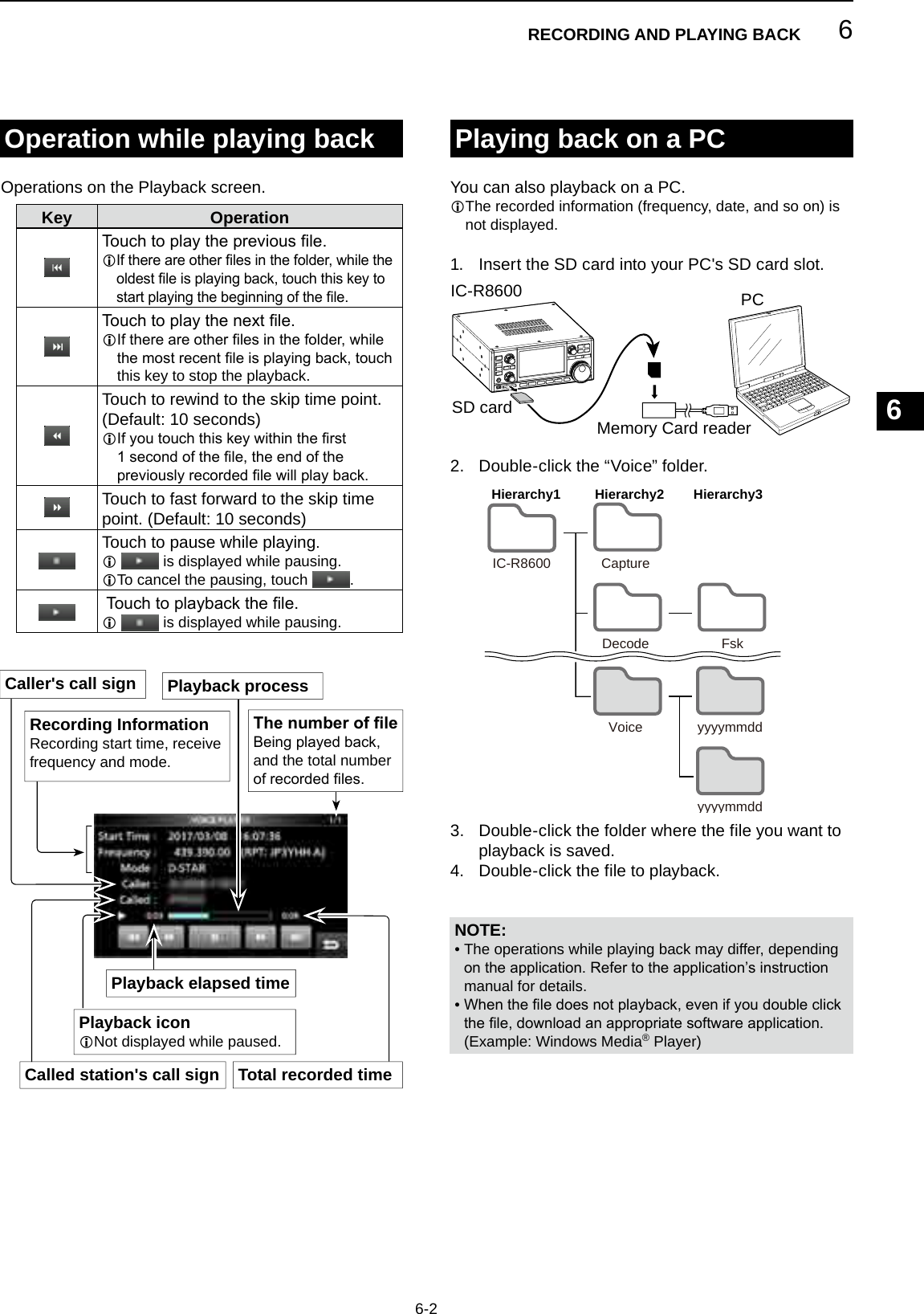
![6RECORDING AND PLAYING BACK6-16-1RecordingYou can record the received audio onto an SD card. DQuick recordingYou can quickly start to record the receive audio.1. Push QUICK.2. Touch [<<REC Start>>]. • Startsrecordingand“Recordingstarted.”isbrieydisplayed and the SD card LED starts to blink.3. Push QUICK again.4. Touch “<<REC Stop>>.” • Stopsrecordingand“Recordingstopped.”isbrieydisplayed. DNormal recordingYoucanstarttorecordafteryouconguretherecording settings.1. Open the RECORD screen.MENU » RECORD2. If you want to change the recorder setting, touch [Recorder Set]. (p. 6-4)3. Touch “<<REC Start>>.” • Recording starts.4. Touch “<<REC Stop>>.” • Stopsrecordingand“Recordingstopped.”isbrieydisplayed.5. To close the RX RECORDER screen, push EXIT.NOTE: • An SD card (user supplied) is required. • As the default setting, the recording is paused while the squelch is closed, and resumes when a signal is received. You can continue recording regardless of the signal presence. (p. 6-4) • If your SD card does not have an "IC-R8600" folder, back up any data on the SD card, insert it in the receiver's card slot and then format it using the built-in format function. See “Formatting an SD card” (p. 7-2) for details. • Once the recording starts, it continues, even if the receiver is turned OFF and ON again. • The recording continues until you touch <<REC Stop>> or the free space on the SD card has run out. • Whentherecordingle’scontentbecomes2GB,thereceivercontinuestorecord,buttoanewle.InformationL: Record indication • While recording: • While the recording is paused:SDPlaying back1. Open the PLAY FILES screen.MENU » RECORD > Play Files2. Select a folder that contains the file you want to playback. • Thelelistisdisplayed.3. Select the desired file. • Starts a playback.LPlaybackcontinuestothenextle,andstopswhenthelastleinthefolderisplayedback.4. To close the PLAY FILES screen, push EXIT several times.Blinksinblue](https://usermanual.wiki/ICOM-orporated/381801/User-Guide-3440284-Page-42.png)
![6RECORDING AND PLAYING BACK6-3Checking the le informationTheIC-R8600candisplaytherecordedle’soperating frequency, operating mode, date, and so on.1. Open the PLAY FILES screen.MENU » RECORD > Play Files2. Select a folder that contains the file you want to check. • Thelelistisdisplayed.L Touch a folder for 1 second to check the folder information. 3. Touch the file you want to check for 1 second. • The QUICK MENU screen opens.4. Touch “File Information.”5. To close the PLAY FILES screen, push EXIT several times.Deleting a leYoucandeletetherecordedaudiole.1. Open the PLAY FILES screen.MENU » RECORD > Play Files2. Select a folder that contains the file you want to delete. • Thelelistisdisplayed.3. Touch the desired file to delete for 1 second. • The QUICK MENU screen opens.4. Touch “Delete.” • Touch"DeleteAll"todeletealllesinthefolder.5. Touch [YES] on the confirmation dialogue. • Theselectedleisdeleted.6. To close the PLAY FILES screen, push EXIT several times.](https://usermanual.wiki/ICOM-orporated/381801/User-Guide-3440284-Page-44.png)
![6RECORDING AND PLAYING BACK1234567891011121314151617181920216-4Deleting a folder1. Open the PLAY FILES screen.MENU » RECORD > Play Files2. Touch the folder to delete for 1 second.3. Touch “Delete.” • Touch “Delete All Folders” to delete all folders at one time.4. Touch [YES] on the confirmation dialogue. • The selected folder is deleted.5. To close the PLAY FILES screen, push EXIT several times.You can delete the recorded audio folder.NOTE:Allthelesinthefolderarealsodeleted.RECORDER SET screenYou can change the RECORDER SET settings.1. Open the RX RECORDER screen.MENU » RECORD2. Select “Recorder Set.”3. Select an item.4. Select the desired option or value.5. To close the RECORDER SET screen, push EXIT several times.REC Condition (Default: Squelch Auto)Select the recording condition for receive. • Always: Records even if no signal is received. • Squelch Auto: Records only when the squelch opens. ( The recording will be paused when the squelch closes while recording.)File Split (Default: ON)Turn the File Split function ON or OFF. • OFF: Theaudioiscontinuouslyrecordedintotheleeven if the squelch status changes between open and closed. Whentherecordingle’ssizebecomes 2GB,theIC-R8600continuestorecord,buttoanewle. • ON: While recording, and if the squelch status changesbetweenopenandclosed,anewleis automatically created in the same folder, and the audio is saved into the new one.TIP: How to reset to the default settingTouching the item or its option for 1 second displays the Quick menu, and then touch “Default” to reset to the default setting.PLAYER SET screenYou can change the fast forward or rewind skip time in the PLAYER SET screen.1. Open the RX RECORDER screen.MENU » RECORD2. Select “Player Set.”3. Touch “Skip Time.”4. Select an option.5. To close the RECORDER SET screen, push EXIT several times.](https://usermanual.wiki/ICOM-orporated/381801/User-Guide-3440284-Page-45.png)
![7USING AN SD CARD7-17-1About the SD card Saving data onto the SD cardThe SD and SDHC cards are not supplied by Icom. User supplied.You can use an SD card of up to 2 GB, or an SDHC of up to 32 GB. Icom has checked the compatibility with the following SD and SDHC cards.(As of March 2017) • Brand: SanDisk® • Type: SD (2 GB) and SDHC (4, 8, 16 and 32 GB)L The above list does not guarantee the card’s performance.L Throughout the rest of this document, the SD card and an SDHC card are simply called the SD card or the card. TIP: Icom recommends that you save the receiver’s factory default data for backup.NOTE: Format all SD cards to be used with the receiver with the built-in Format function. Format, even preformatted cards for PCs or other uses. (p. 7-2)NOTE: • Before using the SD card, thoroughly read the card’s instructions. • If you do any of the following, the card data may be corrupted or deleted. - You remove the card from the receiver while the card is being accessed. - A power failure occurs or the power cable is disconnected while the card is being accessed. - You drop, impact or vibrate the card. • Do not touch the contacts of the card. • The receiver takes a longer time to recognize a large capacity card. • The card will get warm if continuously used for a long period of time. • The card has a certain lifetime, so data reading or writing may not be possible after using it for a long period. When reading or writing data is impossible, the card’s lifetime has ended. In that case, use a new one. We recommend you make a separate backup le of the important data onto your PC. • Icom will not be responsible for any damage caused by data corruption of a card.You can save the following data onto the card: • Data settings of the receiver Memory channel contents saved in the receiver. • Communication contents The recorded audio. • Communication log The receive history log. • FSK (RTTY) decode log The received FSK decode history log. • Captured screensInserting or removing the SD card DInserting Insert the card into the slot until it locks in place, and makes a ‘click’ sound. • Displays the SD card icon when the SD card is inserted.LBe sure of the card orientation. DRemoving (While the receiver is OFF) Push in the SD card until a click sounds. • The card is unlocked, and you can pull it out.L If you remove the SD card while the receiver’s power is ON, be sure to unmount it.Inserting RemovingLights blue Turns OFF 1. Push2. PullCutoutLOCKSDLOCKSD DRemoving (While the receiver is ON) Proceed the unmount as shown below, otherwise the data may be corrupted or deleted.1. Open the SD CARD screen.2. Touch [Unmount]. • Unmount conrmation dialogue appears.3. Touch [YES]. • "Unmount is completed." is displayed.4. Push the SD card, then pull it out. DSD card’s folder contentsThe following folders are created in the SD card.q All folders are contained in this folder.w The captured screen data (‘.png’ or ‘.bmp’).e The FSK decode log folder is created.r The received FSK decode log data (‘.txt’ or ‘.html’).t The receive history log data (‘.csv’).y The receiver’s setting data (‘.icf’).u The recorded audio data folders are created.i Recorded audio les (‘.wav’).IC-R8600q we rtyu iiCaptureDecode FskyyyymmddyyyymmddRxLogSettingVoiceThe folder name is automatically created in the following format: yyyymmdd (yyyy:Year, mm:month, dd:day)Hierarchy1 Hierarchy2 Hierarchy3](https://usermanual.wiki/ICOM-orporated/381801/User-Guide-3440284-Page-46.png)
![7USING AN SD CARD1234567891011121314151617181920217-2Formatting an SD cardBefore using an SD card with the receiver, be sure to format all SD cards with the built-in Format function. This creates a special folder on the card that you need for operations like updating the rmware.Format all cards, including a brand new SD card, and even preformatted cards for PCs or other uses.NOTE: Formatting a card erases all its data. Before formatting any used card, back up its data onto your PC.IMPORTANT: Even if you format an SD card, some data may remain in the card. When you dispose the card, be sure to physically destroy it to avoid unauthorized access to any data that remains.1. Insert an SD card into the card slot.2. Open the SD CARD set screen.MENU » SET > SD Card3. Touch [Format]. • The format conrmation dialogue appears.4. Touch [YES] to start formatting. • After formatting, returns to the SD CARD screen.5. To close the SD CARD screen, push EXIT several times.After you update the receiver’s rmware, the “Save Form” item will be added on the SD CARD screen.MENU » SET > SD Card > Save FormWith this item, you can select the rmware version to save the setting data onto an SD card. You can write the setting le that is saved in an earlier version to an earlier rmware version IC-R8600.L Depending on the receiver’s rmware version, this item may not be displayed. In that case, save the le in the current version.LSee page 13-1 for details of the rmware update.NOTE: • If you select “Old Ver (xxx - xxx),” a function that is added when the receiver’s rmware format is updated will not be saved. • You cannot write a setting le that is saved in the current version format to an earlier rmware version IC-R8600.You can save the Memory channels and the receiver’s settings onto an SD card.1. Insert an SD card into the card slot.2. Open the SAVE SETTING screen.MENU » SET > SD Card > Save Setting3. Select “<<New File>>.”SAVE SETTING screenL The le name is automatically set in the following format: Setyyyymmdd_xx (yyyy: Year, mm: month, dd: day, xx: serial number)TIP: After you update the receiver’s rmware, the “Save Form” item will be added on the SD CARD set screen. If this item is set to the earlier rmware version, the conrmation window is displayed. When you want to save the data in the earlier rmware version, touch [YES].4. Touch [ENT]. 5. Touch [YES]. • Saves the data settings.L While saving to the card, the SD card icon blinks.L After saving, returns to the SD CARD screen.6. To close the SD CARD screen, push EXIT several times.Saving the setting dataSaving in the old format](https://usermanual.wiki/ICOM-orporated/381801/User-Guide-3440284-Page-47.png)
![7USING AN SD CARD7-3Loading the data lesYou can load the Memory channels and receiver’s settings from the card to the receiver.TIP: Saving the current data is recommended before loading other data into the receiver.1. Open the LOAD SETTING screen.MENU » SET > SD Card > Load Setting2. Select the file you want to load.LOAD SETTING screen3. Select a loading option.L Choose “ALL” when you load all the receiver settings. 4. Touch the desired loading items. • “✓” is displayed left side of the selected option.L The Set mode settings and Memory channel contents are always loaded.5. Touch “<<Load>>.” • The load conrmation dialogue appears.6. Touch [YES]. • Starts le loading.L When you select “REF IN/OUT, REF Adjust” in step 4, “The new "REF IN/OUT, REF Adjust" setting will be saved” is displayed.7. After the loading has been completed, “Restart the IC-R8600” is displayed.L Turn OFF the receiver power, then turn ON again.Deleting a data leNOTE: Deleted data from a card cannot be recalled. Before deleting any data, back up the card data onto your PC.1. Open the SAVE SETTING screen.MENU » SET > SD Card > Save Setting2. Touch the file desired to delete for 1 second.3. Touch “Delete.”LTo delete all les, touch “Delete All.”LTo cancel deleting, push EXIT. • The delete conrmation dialogue appears.4. Touch [YES]. • Deletes the selected le.LAfter deleting, returns to the SAVE SETTING screen.5. To close the SD CARD screen, push EXIT several times.Checking SD card information1. Open the SD CARD screen.MENU » SET > SD Card2. Touch to select “SD Card Info.” • Opens the SD CARD INFO screen.3. To close the SD CARD screen, push EXIT several times.](https://usermanual.wiki/ICOM-orporated/381801/User-Guide-3440284-Page-48.png)
![8-18MEMORY OPERATIONMemory channels Selecting channel groupGROUPS MEMORYCHANNELS USAGEGroup 00 ~ 99(100 groups) 00 ~ 99Has 100 memory groups.L Up to 2000 channels can be separately stored in the 100 memory channel groups.Auto Memory Write channelsA000 ~ A199(200 channels)Automatically stores frequencies into each 200 channels when a signal is received during an Auto Memory Write scan.Scan Skip channelsS00 ~ S99(100 channels)100 scan skip channels can be stored into the memory channels. These scan skip channels are used for the Programmable scan, Fine Programmable scan, Auto Write Memory scan, ∂F scan, Fine ∂F scan and Programmable Skip scan. Program Scan EdgesP00A /P00B~ P49A/P49B(50 pairs)50 pair of scan edges for the lower and upper frequency edges can be programmed.L The same pair of frequencies are written as the default.L You cannot clear nor leave them blank. DSelecting with / 1. Push V/M to select the Memory mode.2. Push or to select the group.L You can select only groups that contain a channel.L In the VFO mode, you can select blank groups. DSelecting on the GROUP SELECT screen1. Touch the Memory channel number.2. Touch [GROUP].3. Rotate and touch to select a memory group (00 ~ 99, A, S or P).4. Push to close the VFO/MEMORY screen.Group No.(Example:00)Group No.(Example:01)Program scan edge[Memory channel tree view]123456789101112131415161718192021Group50 pairs100 channels200 channelsUp to 2000 channels**100 channels in each groupMemory Channel Group 00Memory Channel Group 99Auto Memory Write Channel A000Auto Memory Write Channel A199Program Scan Edge P00A/P00BProgram Scan Edge P49A/P49BMemory Channel 00Memory Channel 99Scan Skip Channel S00Scan Skip Channel S99](https://usermanual.wiki/ICOM-orporated/381801/User-Guide-3440284-Page-49.png)
![8MEMORY OPERATION8-2 z Rotate or to select the desired memory channel.L Only the Memory channels that have contents are displayed. A single memory channel stores the frequency, receive mode and IF lter width besides the following items.• Tuning step • DUP direction• P.AMP ON/OFF • TSQL/DTCS setting• ATT setting • DIGITAL Squelch settings• Antenna setting • Memory name• IP+ ON/OFF • SKIP Setting• DUP mode • SELECT Setting1. Set the frequency and receive mode and so on.2. Push .3. Touch to select the desired memory write option.[Write to a New Channel]:• The contents such as frequency and operating mode are written to a blank channel in the selected group.[Write to the Selected Channel]:• The selected channel is overwritten.[Select the Channel and Write]:• The channel is written to the channel selected on the CH SELECT screen.Selecting a memory channel Writing a memory channel (Example: Memory channel 04)Memory modeGroup number Channel number DSelecting with 1. Push V/M to select the Memory mode.2. Rotate to select the desired memory channel. DSelecting with 1. Push V/M to select the Memory mode.2. Push . • LED on the key lights.3. Rotate to select a memory channel. DSelecting using the keypad1. Touch the memory channel number. • The VFO/MEMORY screen is displayed.2. Push or to select the group.3. Touch [CH-INP].4. Touch the numeric keys to enter the desired memory channel number.5. Touch [ENT] to set the entered memory channel.6. Push to close the VFO/MEMORY screen.Memory write optionsNumber of remaining blank channelsChannel numberMemory contentsGroupMemory name(if entered)Insert a new channel without overwriting the selected channel.CH SELECT screen exampleInformationL: Selecting a memory channel in a different groupYou can select the desired Memory channel stored in all memory channel groups.1. Push , and touch [Channel Select Group Range].2. Touch [All Groups].3. Rotate to continuously select a memory channel in all memory channel groups.](https://usermanual.wiki/ICOM-orporated/381801/User-Guide-3440284-Page-50.png)
![8-3Clearing a memory channelCopying the Memory contentsInserting a blank channelWhen you clear a memory channel, you can choose whether to leave the cleared channel blank as a place holder, or keeping the deleted channel number.LYou cannot clear program scan edge channels.1. Touch the Memory channel number. • The VFO/MEMORY screen is displayed.2. Rotate to select the channel you want to clear.3. When clearing the memory channel contents: zTouch [M-CLR] (Memory Clear) for 1 second. • Beeps sound and the selected memory contents are cleared but the memory channel remains as a blank channel. When deleting the channel: zTouch [M-DEL] (Memory Delete) for 1 second. • Beeps sound and the memory channel is completely deleted.4. Push to close the VFO/MEMORY screen.You can copy the Memory contents to the VFO.1. Push V/M to select the Memory mode.2. Select the memory channel to be copied.3. Hold down V/M for 1 second. • Beeps sound and the selected memory contents are copied to the VFO.4. Push V/M to select the VFO mode to confirm that the memory contents were successfully copied.You can insert a blank channel between 2 Memory channels.L This function is convenient to organize your memory channels.1. Touch the Memory channel number. • The VFO/MEMORY screen opens.2. Select the channel to insert a blank channel below.3. Touch [M-INS] for 1 second. • Beeps sound and a blank channel is inserted below the selected memory channel.4. Push to close the VFO/MEMORY screen.Memory modeVFO modeBlank channelBlank channelNext channel contents8MEMORY OPERATION123456789101112131415161718192021](https://usermanual.wiki/ICOM-orporated/381801/User-Guide-3440284-Page-51.png)
![8MEMORY OPERATION8-4Entering a group/memory nameYou can assign a name of up to 16 characters to each channel group (00 ~ 99) and memory channel. • You cannot change the group name of Auto MW, Skip and scan channels (Groups "A," "S" and "P"). DEntering a group name1. Touch the Memory channel number. • The VFO/MEMORY screen opens.2. Touch [GROUP].3. Select the channel group to enter a name.4. While the channel group is selected, touch QUICK.5. Touch “Edit Name.” • The “GROUP NAME” editing screen is displayed.6. Enter a name of up to 10 characters.L See “Keyboard entering and editing” (p. 1-8) for details.7. Touch [ENT] to save the entered name. • The MEMORY NAME screen closes and returns to the GROUP SELECT screen. DEntering a memory name1. Open the MEMORY screen.MENU » MEMORY2. Push or to select the group.3. Rotate to select the channel to enter a name.4. Touch .5. Touch “Edit Name.” • The “MEMORY NAME” editing screen is displayed.6. Enter a name of up to 10 characters.L See “Keyboard entering and editing” (p. 1-7) for details.7. Touch [ENT] to save the entered name. • The MEMORY NAME screen closes and returns to the MEMORY screen.Memory name](https://usermanual.wiki/ICOM-orporated/381801/User-Guide-3440284-Page-52.png)
![8-5About the MEMORY screenq Memory channel group and channel number Displays the Memory group (00 ~ 99, A, S and P), and Memory channel number (00 ~ 99, A000 ~ A199, S00 ~ S99 and P00A/P00B ~ P49A/P49B) in each group.w Frequency Displays the entered frequency.e Receive mode Displays the selected receive mode.r Memory menu Touch to display the MEMORY MENU.L “SKIP,” “Edit Name,” “Memory Write” or “Memory Clear” is selectable.t [▲]/[▼] key Touch to scroll the memory channel list.L To select a memory channel in a different group, refer to page 8-2.y Memory name Displays the memory name, if entered.L To assign a memory name, refer to page 8-4.u Select memory icon Touch this icon to set the Select number “1” ~ “9” or OFF.L To clear the Select memory setting, touch this icon for 1 second, then select a clearing option.You can edit the Memory channel contents on this screen. z Open the MEMORY screen.MENU » MEMORYwrqeyutMemory screen exampleInformationL: You can also edit the memory channel in the QUICK MENU.Example: Moving or copying a memory channel1. Push to open the QUICK MENU.2. Select the channel you want to move or make a copy of.3. Open the QUICK MENU on the MEMORY screen.4. Touch [Move Channel] or [Memory Copy].5. Rotate to select the destination channel.6. Push .7. Push to close the QUICK MENU.8MEMORY OPERATION123456789101112131415161718192021](https://usermanual.wiki/ICOM-orporated/381801/User-Guide-3440284-Page-53.png)
![9-1Scan typesBasic scanningSCAN TYPE SCANNING DETAILSVFO SCANPROGRAMMED SCAN Repeatedly scans between 2 Scan Edge frequencies of Program Scan Edge memory channels. The scan starts from the lower edge frequency. (p.9-4)FINE PROGRAMMED SCANDuring a Programed scan, the scan speed decreases when the squelch opens, but the receiver keeps scanning. The scan tuning step changes to 10 Hz when the squelch opens. ∂F SCAN Repeatedly scans within the ∂F span area. The scan starts from the center frequency, then upper edge and lower edge. (p.9-5)FINE ∂F SCAN During a ∂F scan, the scan speed decreases when the squelch opens, but the receiver keeps scanning. The scan tuning step changes to 10 Hz when the squelch opens. AUTO MEMORY WRITE SCANDuring a Programed scan, and when a signal is received, the frequency is automatically stored into an Auto Memory Write channel group. (p.9-6)MEMORY SCANMEMORY SCAN Repeatedly scans memory channels, including Skip and Auto Write memory channels. You can select the group and the scan edge channel. (p.9-7)SELECT MEMORY SCAN Repeatedly scans all or one of 9 Select Memory channels. (p.9-7)MODE SELECT MEMORY SCANRepeatedly scans the memory channels with the selected receive mode (ignoring other receive modes). (p.9-9)PRIORITY SCAN Periodically monitors a selected memory channel while receiving a signal on VFO. (p.9-2)Adjusting the scan speedAdjust the scan speed for slower or faster scans.1. Push . • The setting menu opens.2. Touch [SCAN SPEED].3. Rotate . • Setting range: 1 (slow) ~ 30 (fast)L You cannot change the scan speed during a Fine Program scan or Fine ∂F scan.Push to start or stop a scan, then touch the desired scan type.L See the following pages for the Scan setting details. (p. 9-3) DVFO scan and Memory scan1. Push . • If you started a scan of the same scan type before, hold down for a second, to start the same scan.2. Touch the desired scan type. • The SCAN screen opens, and the scan starts.L Rotating changes the scan direction: Rotate right for the up scan, rotate left for the down scan.L To cancel the scan, push .L You can hide the SCAN screen during a scan. Set [Display SCAN Screen (at SCAN START)] item to "OFF" on the SCAN SETTING screen. (p. 9-3)SCAN START screen DPriority scanFollow the procedure below to start or stop a Priority scan..LSee page 9-2 for setting priority channel.1. Push . • "PRIO" is displayed.L Hold down for 1 second to monitor the priority channel.2. Push again to cancel the scan.9SCANS](https://usermanual.wiki/ICOM-orporated/381801/User-Guide-3440284-Page-54.png)
![9-2Priority scanA priority scan periodically checks a selected memory channel* while receiving on a VFO frequency.* Memory channel, Auto Memory Write channel, Scan Skip Channel or Program Scan Edge Channel. DPriority scan operation1. Open the SCAN screen.MENU » SCAN2. Touch [TYPE/SET].3. Touch [PRIO].4. Touch [SELECT] to select the item to change. • No.: Priority memory preset number (0 ~ 9) (You can save up to 10 pairs of Group and Ch.) • Group: Memory Group number • Ch: Memory channel number.5. Rotate to change the setting.LYou cannot select blank channels.6. Touch [SELECT] several times to exit the edit mode, then touch [START] or push . • A Priority scan starts. • To cancel the scan, push or touch [STOP].7. To close the SCAN screen, push . DMonitoring the Priority channel z During a Priority scan, hold down for 1 second to monitor the priority channel. • "PRIO" is displayed while monitoring. • Push to cancel the monitoring.Setting the Scan Resume function DSetting the Scan Resume functionYou can set the Scan Resume options for when the signal disappears.1. Hold down for 1 second. • The SCAN DELAY screen opens.2. Touch the resume condition option. • [OFF]: The scan pauses until the signal disappears. • [DELAY]: When a signal is received, the scan pauses for the preset delay period, then resumes. (Set the delay by rotating .) • [∞](Innity): Thescaniscancelledwhenasignal is received. DSetting the scan delay timerYou can set the delay time that the scan restarts after the signal disappears. zRotate . • Setting range: 1 ~ 30 secondsLThe delay amount is displayed while setting.L If a signal is received before the delay time has expired, the timer restarts.L When the Scan Resume function is set to [OFF] or [∞], the scan delay is not activated.90.6 MHz (VFO)BlinksSCAN screenSetting the priority intervalPriority scan checks the priority channel according to the set interval.1. Push . • The setting menu opens.2. Touch [PRIO INTVL].3. Rotate . • Setting range: 1 ~ 15 seconds9SCANS123456789101112131415161718192021(Example)145 MHz (Memory channel)](https://usermanual.wiki/ICOM-orporated/381801/User-Guide-3440284-Page-55.png)
![9SCANS9-3Temporary Skip Timer (Default: 5min)Sets the period of time of the Temporary Skip timer.The Skip timer ignores the Temporary Skip signal for the set period of time. • Options: 5, 10 and 15 minutesSKIP function (Default: ON)Sets the Skip (SKIP or PSKIP) function. • OFF: Turns OFF the function. (You can use the Temporary Skip function (p. 9-10).) • ON: The scan skips the memory channels that are programmed as skip channels.Auto MW (Memory Write) SCAN Memory Clear (Default: Display Dialog)Selects the option to start an Auto Memory Write Scan. • OFF: Starts an MW scan without clearing Auto Write memory channels (A000 ~ A199). • Display Dialog: Asks whether or not to clear Auto Write memory channels (A000 ~ A199) before starting an MW scan. • ON: Automatically clears Auto Write memory channels (A000 ~ A199) before starting an MW scan.Display SCAN Screen (at SCAN START) (Default: ON)Selects whether or not to display the SCAN screen when you push to start a scan (except Priority scan).• OFF: Does not display the SCAN screen. • ON: Displays the SCAN screen.MAIN DIAL Operation (SCAN) (Default: Up/Down)Selects the scan operation when you rotate during a scan. • OFF: Cancels the scan. • ON: Changes the scan direction. Rotate right for an up scan, rotate left for a down scan.Scan Setting screenConguretheScanontheScanSettingscreen.1. Open the SCAN screen.MENU » SCAN2. Touch [TYPE/SET].3. Touch [SET].4. Touch to select the desired item.5. Touch to select the desired option.L See the right column for setting items and options.6. To close the SCAN SET screen, push EXIT.TIP: How to reset to the default settingTouching the item or its option for 1 second displays the Quick menu, and then touch “Default” to reset to the default settings.SCAN screenSCAN SET screen](https://usermanual.wiki/ICOM-orporated/381801/User-Guide-3440284-Page-56.png)
![9-4Programmed scan and Fine Programmed scanProgrammed scan and Fine Programmed scanRepeatedly scans between two Scan Edge frequencies (P00A/P00B ~ P49A/P49B).L To change the Scan Edge Memory channels, see “Writing a memory channel” for details. (p. 8-2)L If the both Scan Edges are the same frequencies, the Programmed scan does not start.L In the Fine Programmed scan, the scan speed decreases when the squelch opens, but the receiver keeps scanning. The scan tuning step changes to 10 Hz when the squelch opens. DProgrammed scan operation1. Open the SCAN screen.MENU » SCAN2. Touch [TYPE/SET].3. Touch [PROG].4. Touch [SELECT] to select the item* to change, * Scan edge channel number (Example: P00A/P00B), scan edges (lower and upper frequencies), receive mode,lterandtuningstep(TS).5. Rotate , or to touch [EDIT] to change the setting.L The changed settings are stored in the Program Scan Edge channel.6. Touch [SELECT] several times to exit the edit mode, then touch [START] or hold down for 1 second. • The Programmed scan starts.LTouch [STOP] or push to cancel the scan.7. To close the SCAN screen, push EXIT. DFine Programmed scan operation1. Start a Programmed scan.L See steps 1 ~ 6 in “Programmed scan operation” to the left for details.2. While Programmed scanning, touch [FINE].L Each touch toggles the Programmed scan and the Fine Programmed scan.LTo cancel the scan, touch [STOP] or push .3. To close the SCAN screen, push EXIT.BlinksRecalls the VFO frequency before the scan startsJumps to the lower edgeWhile Programmed scanningWhile Fine Programmed scanningBlinksBlinks9SCANS123456789101112131415161718192021P00A144 MHz P00B148 MHz(Example) P00A/00BScanJumpLoweredgeUpperedge](https://usermanual.wiki/ICOM-orporated/381801/User-Guide-3440284-Page-57.png)
![9SCANS9-5∂F scan∂F scan and Fine ∂F scan100 kHz 100 kHz93.3 MHz 93.4 MHz93.2 MHzRepeatedly scans within the ∂F span area. The scan starts from the center frequency of VFO or selected memory channel.LInne∂F scan, the scan speed decreases when the squelch opens, but the receiver keeps scanning. The scan tuning step changes to 10 Hz when the squelch opens. D∂F scan operation1. Select the VFO or Memory mode, then set the center frequency of the scan.2. Open the SCAN screen.MENU » SCAN3. Touch [TYPE/SET].4. Touch [∂F].5. Touch [SELECT] to select the item, then rotate to change the setting. • Set the center frequency and span.L The scan does not start when the tuning step is wider than the span.6. Touch [SELECT] several times to exit the edit mode, then touch [START] or hold down for 1 second. to start the ∂F scan.LTo cancel the scan, touch [STOP] or push .7. To close the SCAN screen, push EXIT. DFine ∂F scan operation1. Start the ∂F scan.L See steps 1 ~ 6 in “∂F scan operation” to the left for details.2. While ∂F scanning, touch [FINE]. • Each touch toggles the ∂F scan and the Fine ∂F scan.LTo cancel the scan, touch [STOP] or push .3. To close the SCAN screen, push EXIT.While ∂F scanningWhile Fine ∂F scanningBlinksBlinksBlinksRecalls the VFO frequency before the scan startsJumps to the lower edge SCAN screen(Example) Span: 100 kHzStartJumpLower edgeUpper edgeCenterfrequency](https://usermanual.wiki/ICOM-orporated/381801/User-Guide-3440284-Page-58.png)
![9-6Auto Memory Write scan DAuto Memory Write scan operation1. Open the SCAN screen.MENU » SCAN2. Touch [TYPE/SET].3. Touch [AUTO].4. Touch [SELECT] to select the item*, then rotate to change the settings. * Program Scan Edge number (Example: P00A/P00B), scan edges (lower and upper frequencies), receive mode,lterandtuningstep(TS).L The changed settings are stored in the Program Scan Edge channel.Auto Memory Write scanWhen a signal is received during a Programmed scan, the frequency is automatically stored into an Auto Memory Write channel group (A000 ~ A199).L When no blank channels is left in group A (A000 ~ A199), the Auto Memory Write scan automatically cancels. You can clear the all channels in group A (A000 ~ A199) every time you start a Auto Memory Write scan. See page 9-3 for details.L The channels in group A (A000 ~ A199) are automatically aligned at the top, and all the blank channels are removed (A000 ~ A199).5. Touch [SELECT] several times to exit the edit mode, then touch [START]. • Theconrmationdialogisdisplayed.6. Touch [YES]. • The Auto Memory Write scan starts.L If you do not want to clear the memory channels in the group A (A000 ~ A199), touch [NO].LTo cancel the scan, touch [STOP] or push .7. To close the SCAN screen, push EXIT.A000A002A001A19985.10080.20076.500– – –– – –BlinksRecalls the VFO frequency before the scan startsJumps to the lower edge SCAN screen9SCANS123456789101112131415161718192021ScanningScan rangeJumpSignalreceived SignalreceivedAuto MW CH groupChannel FrequencySignalreceivedThe received signal frequency is stored into an Automatic Memory Write group](https://usermanual.wiki/ICOM-orporated/381801/User-Guide-3440284-Page-59.png)
![9SCANS9-7Memory scan and Select Memory scanMemory scan99ch00ch 01ch 02ch 03ch04ch05ch06ch50ch98chRepeatedly scans all entered Memory channels except Program Scan Edges.LYou can scan memory channels only in the desired group.LBlank channels are skipped.L If two or more Memory channels are not entered, the Memory scan does not start.Select Memory scan99ch100ch101ch202ch103ch104ch105ch106ch250ch398ch1Repeatedly scans all or one of 9 Select Memory channels (★1 ~ ★9) that are assigned as Select Memory channels.L You can scan Select Memory channels only in the desired group.L If two or more Memory channels are not assigned as a Select Memory channels, the Select Memory scan does not start. DMemory scan operation1. Open the SCAN screen.MENU » SCAN2. Touch [TYPE/SET].3. Touch [MEMO].4. Touch [SELECT] to select the item, then rotate to change the setting. • Set the channel group* and edge channels. * If you do not specify the group, set [Group] to "ALL."5. Touch [SELECT] several times to exit the edit mode, then touch [START]. • The Memory scan starts.LTo cancel the scan, touch [STOP] or push .6. To close the SCAN screen, push EXIT. DSelect Memory scan operation1. Open the SCAN screen.MENU » SCAN2. Touch [TYPE/SET].3. Touch [SEL].4. Touch [SELECT] to select the item, then rotate to change the setting. • Set the channel group*, edge channels and the Select Scan number (Sel No.). * If you do not specify the group, set [Group] to "ALL."5. Touch [SELECT] several times to exit the edit mode, then touch [START] to start the Select Memory scan.LTo cancel the scan, touch [STOP] or push .6. To close the SCAN screen, push EXIT.SCAN screenSCAN screenBlinksDeactivated during a Memory scanBlinksDeactivated during a Memory scan(Example) Group: ALL (Each channel is in the different group.)Blank channels are skipped Only " " tagged channels are scanned."" indicates the Selected (Tagged) Channel.(Example) Group: ALL (Each channel is in the different group.)](https://usermanual.wiki/ICOM-orporated/381801/User-Guide-3440284-Page-60.png)
![9-8Memory scan and Select Memory scan (Continued) DSetting Select Memory channelsRepeatedly scans only Memory channels that are assigned as Select Memory channels (★1 ~ ★9).L You cannot assign the Programed Scan Edge channels (P00A/P49A ~ P00B/P49B) as Select Memory channels.1. Touch the memory channel number.2. Touch [GROUP].3. Rotate , then touch to select the group.4. Rotate to select the Memory channel you want to assign as a Select Memory channel.5. Touch [SELECT] to set the Select scan number.L Each touch changes between“★1” to “★9,” and “(no icon).”6. To close the VFO/MEMORY screen, push EXIT. D Canceling the Select Memory channel settingsYou can cancel the select memory setting, by removing the Select Memory channel assignment (★1 ~ ★9).1. Touch the memory channel number.2. Touch [SELECT] for 1 second.3. Touch the desired option to cancel the Select setting.L Touch [All] to cancel all Select settings (★1 ~ ★9) at a time.4. Touch [YES] to cancel the Select setting.L The selected Select setting is canceled and returns to the previous display.VFO/MEMORY screenDisplayedVFO/MEMORY screen9SCANS123456789101112131415161718192021](https://usermanual.wiki/ICOM-orporated/381801/User-Guide-3440284-Page-61.png)
![9SCANS9-9Mode select memory scan Setting the skip frequency Repeatedly scans the selected receive mode (ignoring other modes) while memory scanning, except Programed Scan Edge channels (P00A/P49A ~ P00B/P49B). DSetting the receive mode1. Select the receive mode.2. Open the SCAN screen.MENU » SCAN3. Touch [TYPE/SET].4. Touch [MODE].5. Touch [SELECT] to select the item, then rotate to change the setting. • Set the channel group and edge channels.LYou cannot change the receive mode on this screen.6. Touch [SELECT] several times to exit the edit mode, then touch [START]. • The mode select memory scan starts.L “MODE SELECT MEMORY SCAN” and decimal points blink while scanning. • Touch [STOP] to cancel the scan.7. To close the SCAN screen, push EXIT.You can set a frequency as a skip frequency that is skipped (ignored) during a VFO scan*.* Programmed scan, Fine Programmed scan, Auto Write Memory scan, ∂F scan and Fine ∂F scan DSetting the skip frequency z Hold down for 1 second while a signal is received and the scan is paused. • The frequency is stored as the Scan Skip channel (S00 ~ S99).L The “PSKIP (Program SKIP)” is displayed on the skip channel.LDuring a VFO scan, the skip frequency is not skipped. DCanceling the skip frequency1. Touch the memory channel number.2. Touch [SKIP].L Each touch changes between “SKIP,” “PSKIP” and “(no icon).”L"PSKIP" disappears and the skip setting is cancelled.3. To close the VFO/MEMORY screen, push EXIT.SCAN screenBlinksDeactivated during a Memory scanVFO/MEMORY screen99chWFM WFM00ch 01ch 02ch 03chWFM AM WFM WFMWFM AM AM WFM04ch05ch06ch50ch98ch(Example) Group: ALL (Each channel is in the different group.)All modes except the WFM are skipped.](https://usermanual.wiki/ICOM-orporated/381801/User-Guide-3440284-Page-62.png)
![9-10You can set a selected memory channel as a Skip channel (SKIP or PSKIP) which is skipped during a memory scan.L You cannot assign the Programed Scan Edge channels (P00A/P49A ~ P00B/P49B) as skip channels.1. Open the MEMORY screen.MENU » MEMORY2. Rotate and touch to select the memory channel you want to set or clear the skip setting.L Push or to change the group.3. Push .4. Touch [SKIP]. • The SKIP screen is displayed.5. Touch the desired option. • OFF: Clears the skip setting. • SKIP: Skipped during a memory scan. (Not skipped during a VFO scan.) • PSKIP: Skipped during a VFO or memory scan. • "SKIP" is displayed.6. To close the MEMORY screen, push EXIT.You can set a frequency as a temporary skip frequency that is skipped (ignored) during a VFO scan* or memory scan, for a period of time (default: 5 minutes).* Programmed scan, Fine Programmed scan, Auto Write Memory scan, ∂F scan and Fine ∂F scan.1. Start a VFO or memory scan.MENU » MEMORY2. Push . • The QUICK MENU is displayed.3. While the scan is paused and if you want to skip the received signal, touch [Temporary Skip].L If you touch during scan, a beep sounds and the QUICK MENU closes. • The Temporary Skip is set, then the scan resumes.Skip channel for memory scanSetting the Temporary SkipMEMORY screenTIP: About the Temporary Skip • You can set up to 5 skip frequencies. When you set the 6th frequency, the oldest frequency will be deleted. • The Temporary Skip is canceled when: - The time that is set to the Temporary Skip Timer item (p. 9-3) has passed. - You turn OFF the receiver power. - You cancel the scan.QUICK MENU9SCANS123456789101112131415161718192021](https://usermanual.wiki/ICOM-orporated/381801/User-Guide-3440284-Page-63.png)
![9SCANS9-11Tone scan operationFM modeThe IC-R8600 can detect subaudible tone frequency or the DTCS code in a received signal. You can determine the tone frequency or DTCS code necessary to open the squelch.1. On the FUNCTION screen, touch [TONE] for 1 second.2. Touch [T-SQL TONE] or [DTCS CODE]. (Example: T-SQL TONE)3. Touch [T-SCAN]. • The Tone scan starts.InformationL • The selected tone frequencies or codes are scanned, and “SCAN” blinks under the frequency readout. • The audio is muted. • The scan speed is slow when the squelch is open, and is fast when the squelch is closed.4. When the tone frequency or code is detected, the tone scan pauses. • The detected frequency or code is automatically set.5. To cancel the scan, touch [T-SCAN] again.LThe last scanned tone frequency or code is displayed.6. To close the TONE FREQUENCY screen, push EXIT.Blinks during scanFM, WFM, AM and SSB modesThe Voice Squelch Control (VSC) function opens the squelch, or stops the scan only when voice components are detected in the signal.LIt is convenient to receive only voice communications.1. Push .2. Touch [VSC]. • Each touch turns the VSC function ON or OFF. • "VSC" appears when the function is ON.3. To close the setting menu, push EXIT.Voice Squelch Control functionLightsDisplayedNOTE:The VSC function is designed to not detect a continuous audio signal. When receiving a signal such as a radio broadcast program that contains a continuous audio, the received audio may be broken up. In such case, turn OFF the VSC function.](https://usermanual.wiki/ICOM-orporated/381801/User-Guide-3440284-Page-64.png)
![10-1Setting the Time and Date NTP Time ServerNOTE: The backup battery for the internal clockThe IC-R8600 has a rechargeable Lithium battery to backup the internal clock. If you connect the receiver to a power source, the battery is charged and it keeps the correct clock setting. However, if you do not connect the receiver to a power source for a long period of time, the battery will discharge. In that case, the receiver resets the internal clock.If you do not use the receiver for a long period, we recommend that you connect the receiver to a power source at least once a month. The charging period is two days whether the receiver’s power is ON or OFF.Manually set date and time without accessing the time management server. DSetting date1. Open the Date screen.MENU » SET > Time Set > Date/Time > Date2. Touch [+] or [–] to set the date.3. Touch [SET] to store the entry.4. To close the Date screen, push EXIT several times. DSetting time1. Open the Time screen.MENU » SET > Time Set > Date/Time > Time2. Touch [+] or [–] to set the current time.3. Touch [SET] to store the entry.4. To close the Time screen, push EXIT several times.The NTP function periodically synchronizes the internal clock with the time management server.L To use this function, an internet connection are necessary. DExecute the time synchronizationThe IC-R8600 accesses the NTP server address that is set in the “NTP Server Address” item.1. Open the DATE/TIME screen.MENU » SET> Time Set > Date/Time2. Touch <<NTP TIME SYNC>>. • The "Connecting to the NTP server" dialog is displayed.3. When the "Succeed" dialog is displayed, touch [OK].4. To close the DATE/TIME screen, push EXIT several times. DSetting the NTP Server address1. Open the DATE/TIME screen.MENU » SET > Time Set > Date/Time2. Touch [NTP Server Address].3. Enter the address using the keypad, then touch [ENT].4. To close the DATE/TIME screen, push EXIT several times.10CLOCK AND TIMER123456789101112131415161718192021](https://usermanual.wiki/ICOM-orporated/381801/User-Guide-3440284-Page-65.png)
![10 Clock and Timer10-2 DSetting the Sleep timerThe Sleep timer automatically turns OFF the receiver power after the set period of time ends. • Settable range : 5 ~ 120 minutes (in 5 minutes steps)1. Hold down for 1 second.2. Touch [Sleep Timer].3. Rotate to set the desired length of time.4. Touch [SET]. • The timer LED lights orange. • 10 seconds before the sleep timer period ends, the receiver starts sounding beeps and the timer LED blinking, then turns OFF.L When the sleep timer ends, the time period set in step 3 is cleared.LEach push of stops and resumes the timer.5. To close the TIMER screen, push EXIT several times. DSetting the Daily timerThe IC-R8600 automatically turns power ON or OFF on the specied day and time.LYou can set up to 3 timer slots for different timer setting.1. Hold down for 1 second.2. Touch to select a timer slot.3. Rotate to set each item for the timer slot. (Example: TIMER1).LSee page 10-3 for each item's details.LPush to reset to the default setting or cancel.4. After you configure the Timer, touch [<<Set>>]. • The "Set Timer?" dialog appears.5. Touch [YES]. • The timer LED lights orange.L When the Power OFF Timer is set: 10 seconds before the sleep timer period ends, the receiver starts sounding beeps and the timer LED blinking, then turns OFF.LEach push of stops and resumes the timer.6. To close the TIMER screen, push EXIT several times.TimerTIMER screenTimer activatedReserved channelDay of the weekPower OFF timePower ON time Repeat ONNOTE: About the Timer accuracySince the Sleep timer counts in ‘minute’ steps (not counts in ‘second’ steps), it may have maximum 59 seconds of error.](https://usermanual.wiki/ICOM-orporated/381801/User-Guide-3440284-Page-66.png)
![10-3Timer Status (Default: OFF)Turns this timer slot ON or OFF. Set to ON to activate the Timer.L is displayed in the slot while the Timer is activated.Reservation Timer (Default: 00:00)Sets the time to turn ON the power in the 24-hour clock.L If you use the Timer to turn OFF the power, push then touch [Clear] to clear the Reservation Timer.Power OFF Timer (Default: --:--)Sets the time to turn OFF the power in the 24-hour clock.L If you use the timer to turn ON the power, push then touch [Clear] to clear the Power OFF Timer.Reservation Channel (Default: ----)Selects the memory channel number that is displayed on start up. When Reservation Timer is set to ON, the IC-R8600 starts with the selected memory channel.L You can select any memory channel except blank one.L If you want to start with currently selected memory channel, push then touch [Clear].L Even if the receiver power is ON, the currently selected memory channel is automatically changed to the selected memory channel.Day of the Week (Default: ---)Selects the day of the week to activate the Timer every week. • If you want to activate the Timer everyday, push then touch [Clear].Repeat Setting (Default: OFF)Selects the timer repeat option. • OFF: The timer activates only once. ( The Timer Status item is automatically reset to "OFF," after the Timer has been activated.) • ON: The Timer activates everyday, or every week if a day of the week is selected.L is displayed in the slot when "ON" is selected.<<Set>> Touch to store the timer settings and starts the Timer.Timer (continued) DAbout the Timer recordingYou can start the recording using the Timer. zStart the recording then turn OFF the power. • When the IC-R8600 is turned on by the Timer, the recording is automatically starts, according to the preset recording setting (p. 6-4). DTimer setting itemsNOTE: If you set the Power OFF timer earlier than Reservation Timer, the receiver will not automatically turn OFF.For example, if Reservation Timer is set to "8:00" and Power OFF timer is set to "7:30," the receiver will not automatically turn OFF.10Clock and Timer123456789101112131415161718192021](https://usermanual.wiki/ICOM-orporated/381801/User-Guide-3440284-Page-67.png)
![11-1Set mode description DEntering the Set mode1. Push MENU. • Opens the MENU screen.2. Touch [SET].3. Rotate to select the desired item.4. Push to go to the next tree level.L You can also go to the next tree level by directly touching the desired item in the screen.LTo go back the previous tree level, push EXIT.5. Repeat steps 3 and 4 to open the desired item’s setting screen. You can use the Set mode to set infrequently changed values or function settings.TIP: The Set mode is constructed in a tree structure.You may go to the next tree level, or go back a level, depending on the selected item.6. Rotate to select the desired option, and then push to set it.InformationL • You can also select the option by directly touching the option or [▲/+] or [▼/–] on the screen. • To continue setting other items in the same tree level, repeat step 6. • To continue setting other items in a different tree level, push EXIT to go back the previous tree level. 7. To close the SET screen, push EXIT several times.TIP: How to reset to the default settingPushing opens the Quick menu, and then touch “Default” to reset to the default settings. MENU screen 11 SET MODE](https://usermanual.wiki/ICOM-orporated/381801/User-Guide-3440284-Page-68.png)
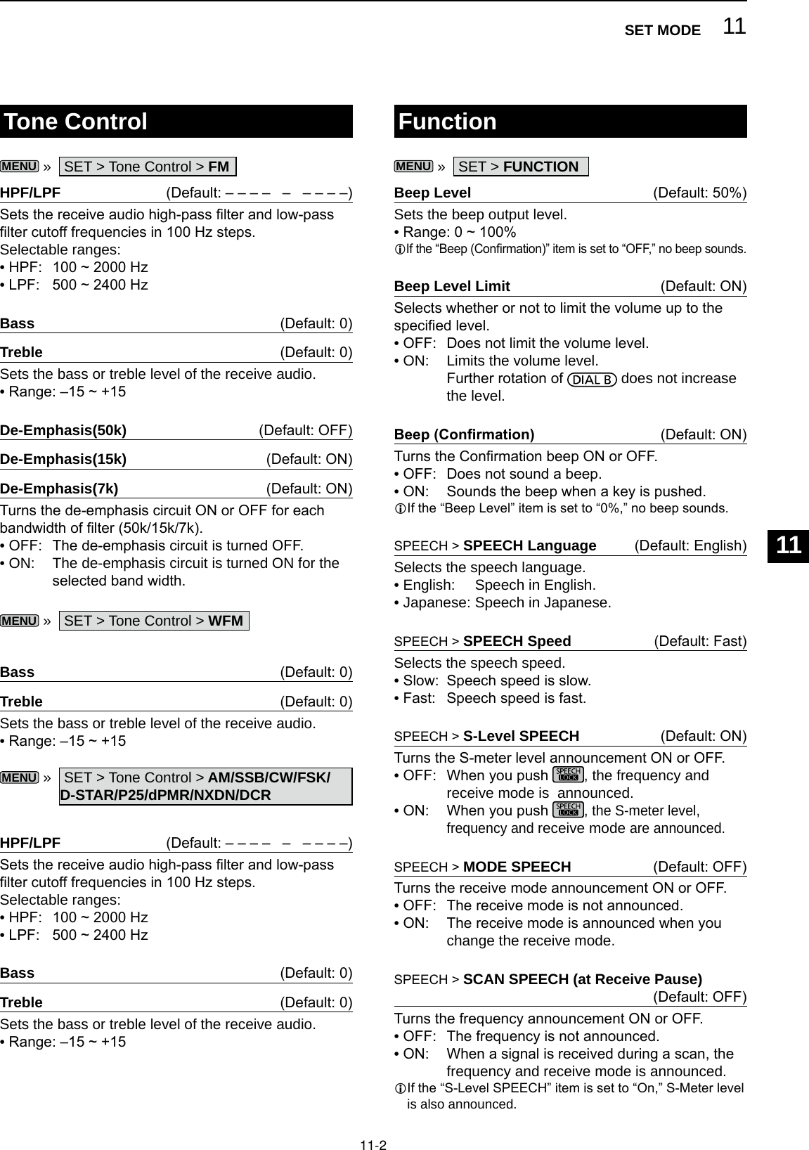
![11 SET MODE11-3SPEECH > SPEECH Output for Ext connectors (Default: All)Selects the announcement condition to output from the external terminals (USB, LAN, AF/IF and EXT-SP). • OFF: The announcement is not output. • Push/Touch: The announcement is output when you push , or touch the screen. • All: The announcement is output when you push or touch the screen, or when a signal is received during a scan.L The announcement is not output if [S-Level SPEECH], [MODE SPEECH] or [SCAN SPEECH] is set to “OFF.”SPEECH > SPEECH Output for Recording (Default: All)Selects the announcement recorded condition. • OFF: The announcement is not recorded. • Push/Touch: The announcement is recorded when you push , or touch the screen. • All: The announcement is recorded when you push or touch the screen, or when a signal is received during a scan.L The announcement is not recorded if [S-Level SPEECH], [MODE SPEECH] or [SCAN SPEECH] is set to “OFF.”SPEECH > SPEECH Level (Default: 50%)Sets the announcement output level. • Range: 0 ~ 100%[SPEECH/LOCK] Switch (Default: SPEECH/LOCK)Selects the key action.• SPEECH/LOCK: Pushing turns ON the Speech function. Holding down turns the Lock function ON or OFF.• LOCK/SPEECH: Pushing turns the Lock function ON or OFF. Holding down turns ON the Speech function.[P.LOCK] Switch (Default: ALL)Selects the action of the key.L and are not locked. • ALL: All controls are disabled. • KEY: All controls except and are disabled.L When you hold down for 1 second, the display backlight is turned OFF.L When “KEY” is selected and while the Panel Lock is activated, rotating or turns ON the display backlight.MAIN DIAL Auto TS (Default: High)Sets the Auto Tuning Step function for MAIN DIAL.When rapidly rotating MAIN DIAL, the tuning step automatically changes according to the rotation speed. • OFF: Auto tuning step is turned OFF. • LOW: Approximately 2 times faster. • HIGH: Approximately 5 times faster when the tuning step is set to 1 kHz or smaller steps. Approximately 2 times faster when the tuning step is set to 5 kHz or larger steps.AFC Limit (Default: ON)Selects whether or not to limit the frequency shift range for the AFC function. • OFF: Does not limit the frequency shift range. • ON: Limits the frequency shift range according to the table below.Receive mode Filter width AFC range limit DIGITAL 5 kHz ±3.5 kHz10 kHz ±7 kHzFM/DIGITAL 7 kHz ±5 kHz15 kHz ±10 kHzFM 50 kHz ±25 kHzWFM 200 kHz ±100 kHz[NOTCH] Switch (AM) (Default: Auto/Manual)[NOTCH] Switch (SSB) (Default: Auto/Manual)Selects the Notch function type in the SSB or AM mode.• Auto: Only the Auto notch lter (AN).• Manual: Only the Manual notch lter (MN).• Auto/Manual: Both the Auto and Manual notch lters.SSB/CW Synchronous Tuning (Default: OFF)Turns the Displayed Frequency Shift function ON or OFF.This function automatically shifts the frequency to match the CW pitch when the operating mode is toggled between SSB and CW. • OFF: Stays on the frequency even when the operating mode is toggled between SSB and CW. • ON: Shifts the frequency when the operating mode is toggled between SSB and CW, to keep receiving the signal.CW Normal Side (Default: LSB)Selects the carrier point in the CW normal mode. • LSB: The LSB side. • USB: The USB side.Screen Capture [POWER] Switch (Default: OFF)Assigns the Screen Capture function to . • OFF: does not act as the Screen Capture key. • ON: acts as the Screen Capture key.Function (Continued)](https://usermanual.wiki/ICOM-orporated/381801/User-Guide-3440284-Page-70.png)
![11-4Function (Continued) Digital Set (Continued)Screen Capture File Type (Default: PNG)Selects the le format for the Screen Capture function. • Options: PNG or BMPKeyboard Type (Default: Full Keyboard)Sets the keyboard entry type to Ten-key or Full Keyboard. • Ten-key: Ten-key type • Full Keyboard: Full Keyboard typeL You can enter upper case letters, lower case letters, numbers, some symbols and spaces with this type.L When the edit screen is displayed, push to open the QUICK menu and select the desired keyboard type.REF AdjustCalibrates the internal reference frequency (10 MHz). • Range: 0 ~ 100%Digital SetMENU » SET > Digital SetDigital Monitor (Default: Auto)Selects the receive mode when is pushed in the DIGITAL mode.• Auto: Receives in the DIGITAL mode or the FM mode, depending on the received signal.• Digital: Receives in the DIGITAL mode.• Analog: Receives in the FM mode.Digital Mode Select (Default: (All modes selected))Selects the DIGITAL mode options. Only checked modes are displayed as the option on the [MODE] screen.• Options: D-STAR, P25, dPMR, NXDN-n, NXDN-vn and DCRRX History Log > RX History Log (Default: OFF)You can store the Received Call logs on to an SD card in CSV format.• OFF: Does not store the log.• ON: Stores the logs.RX History Log > CSV Format > Separator/Decimal (Default: Sep [,] Dec [.])Selects the separator and the decimal character for the CSV format.• Sep [,] Dec [.]: Separator is “,” and Decimal is “.”• Sep [;] Dec [.]: Separator is “;” and Decimal is “.”• Sep [;] Dec [,]: Separator is “;” and Decimal is “,”L The default value differs, depending on the receiver version.RX History Log > Date > Date (Default: yyyy/mm/dd)Selects the date format between “yyyy/mm/dd,” “mm/dd/yyyy” and “dd/mm/yyyy.” (y: year, m: month, d: day)L* The default value may differ, depending on the receiver version.D-STAR Standby Beep (Default: ON)Turns the Standby Beep function ON or OFF. • OFF: Turns OFF the function. • ON: Sounds a beep after a received signal disappears, in the DV (D-STAR) mode.D-STAR Auto Detect (Default: OFF)Turns the DV (D-STAR) mode Automatic Detect function ON or OFF.• OFF: Turns OFF the function. The receive mode is xed to the DV mode.• ON: Automatically and temporarily switches to the FM mode, when an FM signal is received in the DV mode.RX Record (D-STAR RPT) (Default: All)Records the received call history when a DV (D-STAR) signal is received.• ALL: Records up to 50 calls.• Latest Only: Records only the last call.D-STAR EMR AF Level (Default: 20%)Set the audio output level for when an EMR (Enhanced Monitor Request) communication signal is received in the DV (D-STAR) mode.Range: 0 ~ 100%L When an EMR signal is received, the audio will be heard at the set level, or the [AF GAIN] level, whichever is higher.LTo disable the setting, set it to “0%.”11SET MODE123456789101112131415161718192021](https://usermanual.wiki/ICOM-orporated/381801/User-Guide-3440284-Page-71.png)
![11 SET MODE11-5ConnectorsPhones Level Ratio (Default: 1.00)Sets the output ratio of the speaker output level and headphones output level.• Range: 0.40 ~ 2.00AF/IF > Output Select (Default: AF)Selects the signal output from [AF/IF]. • AF: The demodulated AF signal is output. • IF: A 12 kHz IF signal is output.L You can listen to the Digital Radio Mondiale (DRM) broadcast with an application software receiver if it is installed into your PC.AF/IF > AF Output Level (Default: 50%)Sets the AF output level of [AF/IF]. • Range: 0 ~ 100%L At 50% (default), the output level is 200 mV (RMS).AF/IF > AF SQL (Default: OFF (OPEN))Selects whether or not to output the audio from [AF/IF], according to the squelch and signal levels. • OFF(OPEN): The squelch is always opened regardless of the squelch and signal levels. • ON: The squelch opens and closes, according to the squelch and signal levels.AF/IF > AF Beep/Speech... Output (Default: OFF)Sets the Beep and Speech audio output status of [AF/IF]. • OFF: The beep and speech audio are not output from [AF/IF]. • ON: The beep and speech audio are output from [AF/IF].AF/IF > IF Output Level (Default: 50%)Sets the IF output level of [AF/IF]. • Range: 0 ~ 100%L At 50% (default), the output level is 200 mV (RMS).USB (Front) > Output Select (Default: AF)Selects the signal output from [USB] on the front panel. • AF: The demodulated AF signal is output. • IF: A 12 kHz IF signal is output.L You can listen to the Digital Radio Mondiale (DRM) broadcast with the application software receiver that is installed into your PC.USB (Front) > AF Output Level (Default: 50%)Sets the AF output level of [USB] on the front panel. • Range: 0 ~ 100%MENU » SET > Connectors USB (Front) > AF SQL (Default: OFF (OPEN))Selects whether or not to output the audio from [USB] on the front panel, according to the squelch and signal levels. • OFF(OPEN): The squelch is always opened regardless of the squelch and signal levels. • ON: The squelch opens and closes, according to the squelch and signal levels.USB (Front) > AF Beep/Speech... Output (Default: OFF)Sets the Beep and Speech audio output status of [USB] on the front panel. • OFF: The beep and speech audio are not output from [USB] on the front panel. • ON: The beep and speech audio are output from [USB] on the front panel.USB (Front) > IF Output Level (Default: 50%)Sets the IF (12 kHz) output level of [USB] on the front panel. • Range: 0 ~ 100%USB (Front) > Serial Function (Default: FSK Decode)Selects the signal output from [USB] on the front panel. • FSK Decode: An FSK decoded signal is output. • D-STAR Data: A D-STAR data is output.USB (Front) > FSK Decode Baud Rate (Default: 9600)Selects the data transfer rate (Baud rate) of decoded FSK signals from [USB] on the front panel. • Options: 4800, 9600, 19200 or 38400 (bps)USB (Front) > D-STAR Data Baud Rate (Default: 9600)Selects the data transfer rate (Baud rate) of decoded D-STAR data from [USB] on the front panel. • Options: 4800 or 9600 (bps)USB (Rear) > Output Select (Default: AF)Selects the signal output from [USB] on the rear panel. • AF: The demodulated AF signal is output. • IF: A 12 kHz IF signal is output.L You can listen to the Digital Radio Mondiale (DRM) broadcast with the application software receiver that is installed into your PC.USB (Rear) > AF Output Level (Default: 50%)Sets the AF output level of [USB] on the rear panel. • Range: 0 ~ 100%L At 50% (default), the output level is 200 mV (RMS).](https://usermanual.wiki/ICOM-orporated/381801/User-Guide-3440284-Page-72.png)
![11-6Connectors (Continued)USB (Rear) > AF SQL (Default: OFF (OPEN))Selects whether or not to output the audio from [USB] on the rear panel, according to the squelch and signal levels. • OFF(OPEN): The squelch is always opened regardless of the squelch and signal levels. • ON: The squelch opens and closes, according to the squelch and signal levels.USB (Rear) > AF Beep/Speech... Output (Default: OFF)Sets the Beep and Speech audio output status of [USB] on the rear panel. • OFF: The beep and speech audio are not output from [USB] on the rear panel. • ON: The beep and speech audio are output from [USB] on the rear panel.USB (Rear) > IF Output Level (Default: 50%)Sets the IF (12 kHz) output level of [USB] on the rear panel. • Range: 0 ~ 100%USB (Rear) > Serial Function (Default: FSK Decode)Selects the signal output from [USB] on the rear panel. • FSK Decode: An FSK decoded signal is output. • D-STAR Data: A D-STAR data is output.USB (Rear) > FSK Decode Baud Rate (Default: 9600)Selects the data transfer rate (Baud rate) of decoded FSK signals from [USB] on the rear panel. • Options: 4800, 9600, 19200 or 38400 (bps)USB (Rear) > D-STAR Data Baud Rate (Default: 9600)Selects the data transfer rate (Baud rate) of decoded D-STAR data from [USB] on the rear panel. • Options: 4800 and 9600 (bps)LAN > Output Select (Default: AF)Selects the signal output from [LAN]. • AF: The demodulated AF signal is output. • IF: A 12 kHz IF signal is output.L You can listen to the Digital Radio Mondiale (DRM) broadcast with an application software receiver that is installed into your PC.LAN > AF SQL (Default: OFF (OPEN))Selects whether or not to output the audio from [LAN], according to the squelch and signal levels. • OFF(OPEN): The squelch is always opened regardless of the squelch and signal levels. • ON: The squelch opens and closes, according to the squelch and signal levels.LAN > AF Speech Output (Default: OFF)Sets the Speech audio output status of [LAN]. • OFF: The speech audio is not output from [LAN]. • ON: The speech audio is output from [LAN].L You should set the “AF SQL” item to “AF.”CI-V > CI-V Baud Rate (Default: Auto)Selects the CI-V data transfer rate. • Options: 4800, 9600, 19200 (bps) or AutoL When “Auto” is selected, the baud rate is automatically set, according to the data rate of the connected controller.CI-V > CI-V Address (Default: 96h)Selects the CI-V address. • Range: 02h ~ 96h ~ DFhL“96h” is the default address of the IC-R8600.CI-V > CI-V Transceive (Default: ON)Turns the Transceive function ON or OFF. • OFF: The status is not output. • ON: The status is output.CI-V > USB/LAN→REMOTE Transceive Address (Default: 00h)Sets the address used to remotely control the receiver using the optional RS-R8600 (future product), through the [USB] or [LAN] port.The external equipment control signal is output from the [REMOTE] port. • Range: 00h ~ DFhCI-V > CI-V USB (Front) Baud Rate (Default: Auto)Selects the CI-V data transfer rate for [USB] on the front panel. • Options: 4800, 9600, 19200, 38400, 57600, 115200 (bps) or AutoL When “Auto” is selected, the baud rate is automatically set according to the data rate of the connected controller.CI-V > CI-V USB (Front) Echo Back (Default: OFF)Turns the Data Echo Back function ON or OFF, when remotely controlling through the [USB] CI-V port. • OFF: Turns OFF the function. • ON: Turns ON the function.TIP: When multiple devices are connected.The default transceive address is “00h.” To control dedicated equipment when several devices are connected, set the same CI-V address.11SET MODE123456789101112131415161718192021](https://usermanual.wiki/ICOM-orporated/381801/User-Guide-3440284-Page-73.png)
![11 SET MODE11-7Connectors (Continued)CI-V > CI-V USB (Rear) Port (Default: Unlink from [REMOTE])Selects the internal connection type between the [USB] port on the rear panel and the [REMOTE] CI-V port. • Link to [REMOTE]: The [USB] port on the rear panel and the [REMOTE] CI-V port are internally connected. • Unlink from [REMOTE]: The [USB] port on the rear panel and [REMOTE] CI-V port are not internally connected. Each port functions independently. (duplex communication can be made.)CI-V > CI-V USB (Rear) Baud Rate (Default: Auto)Selects the CI-V data transfer rate (bps) for [USB] on the rear panel. • Options: 4800, 9600, 19200, 38400, 57600, 115200 or AutoL When “Auto” is selected, the baud rate is automatically set according to the data rate of the connected controller.L This setting is valid only when the “CI-V USB Port” item is set to “Unlink from [REMOTE].”CI-V > CI-V USB (Rear) Echo Back (Default: OFF)Turns the Data Echo Back function ON or OFF, when remotely controlling through the [USB] CI-V port. • OFF: Turns OFF the function. • ON: Turns ON the function.L This setting is .valid only when the “CI-V USB Port” item is set to “Unlink from [REMOTE].”External Meter Output (Default: Signal)Selects the signal output from [METER]. • Signal: Signal strength. • Signal+SQL: Signal strength and squelch level.External Meter Level (Default: 50%)Sets the voltage level output from [METER]. • Range: 0 ~ 100%L 8 V DC is output at full scale (50%). (into a 10 kΩ load)REF IN/OUT (Default: OFF)Selects the receiver’s reference frequency signal source.• IN: Uses an external reference signal. NOTE: SELECT “OFF” or “OUT” if you are not use a reliable external signal source. When the input signal source level is too low, or the frequency precision is not high, the fre-quency readout blinks and the receiver does not function correctly.• OFF: Does not input/output the reference signal.• OUT: Outputs the internal reference signal.NetworkDHCP (Valid after Restart) (Default: ON)Turns the DHCP function ON or OFF.• OFF: Uses the static IP address.• ON: Uses the DHCP function. If a DHCP server is in your network environ-ment, the IP address is automatically obtained.LThis setting takes effect after restart.IP Address (Valid after Restart) (Default: 192.168. 0. 10)Sets the static IP address.L This setting is valid when “OFF” is selected the [DHCP (Valid after Restart)] item.LThis setting takes effect after restart.Subnet Mask (Valid after Restart) (Default: 255.255.255.0 (24bit))Sets the subnet mask to connect to your PC or LAN (Local Area Network), through the Ethernet. Rotate to set. • Range: 128.0.0.0 (1 bit) ~ 255.255.255.252 (30 bit)LThis setting takes effect after restart.Default Gateway (Valid after Restart) (Default: . . . )When you remotely control the IC-R8600 using the optional RS-R8600 (future product), a default gateway setting is required. L This setting is valid when “OFF” is selected the [DHCP (Valid after Restart)] item.LThis setting takes effect after restart.Primary DNS Server (Valid after Restart) (Default: . . . )If there are two DNS server addresses, enter the pri-mary DNS server address.LThis setting takes effect after restart.2nd DNS Server (Valid after Restart) (Default: . . . )If there are two DNS server addresses, enter the sec-ondary DNS server address.LThis setting takes effect after restart.MENU » SET > Network](https://usermanual.wiki/ICOM-orporated/381801/User-Guide-3440284-Page-74.png)
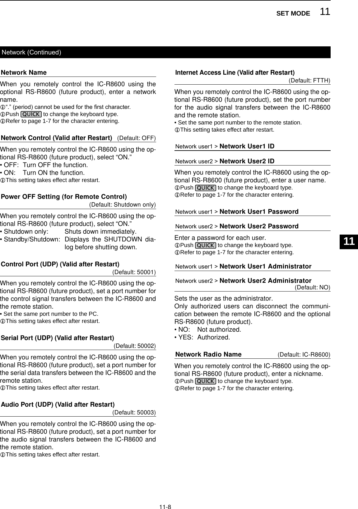
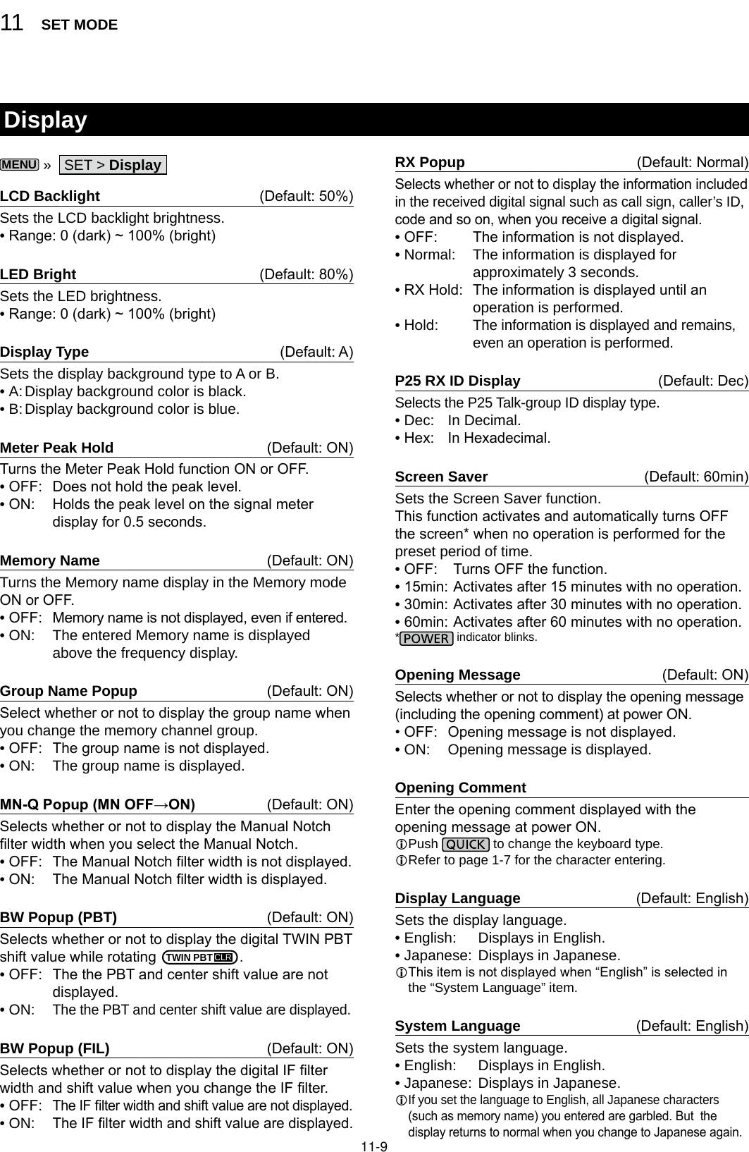
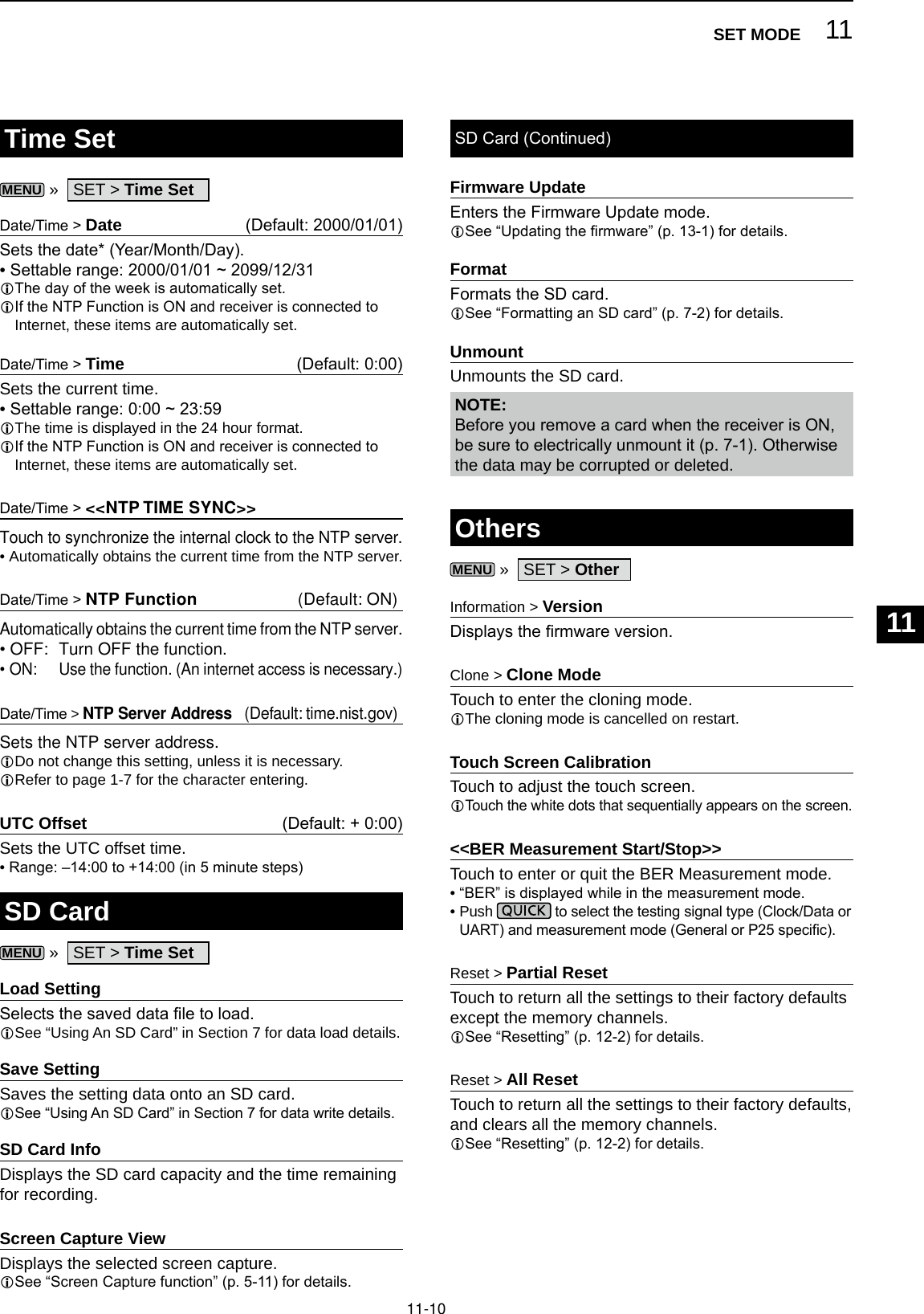
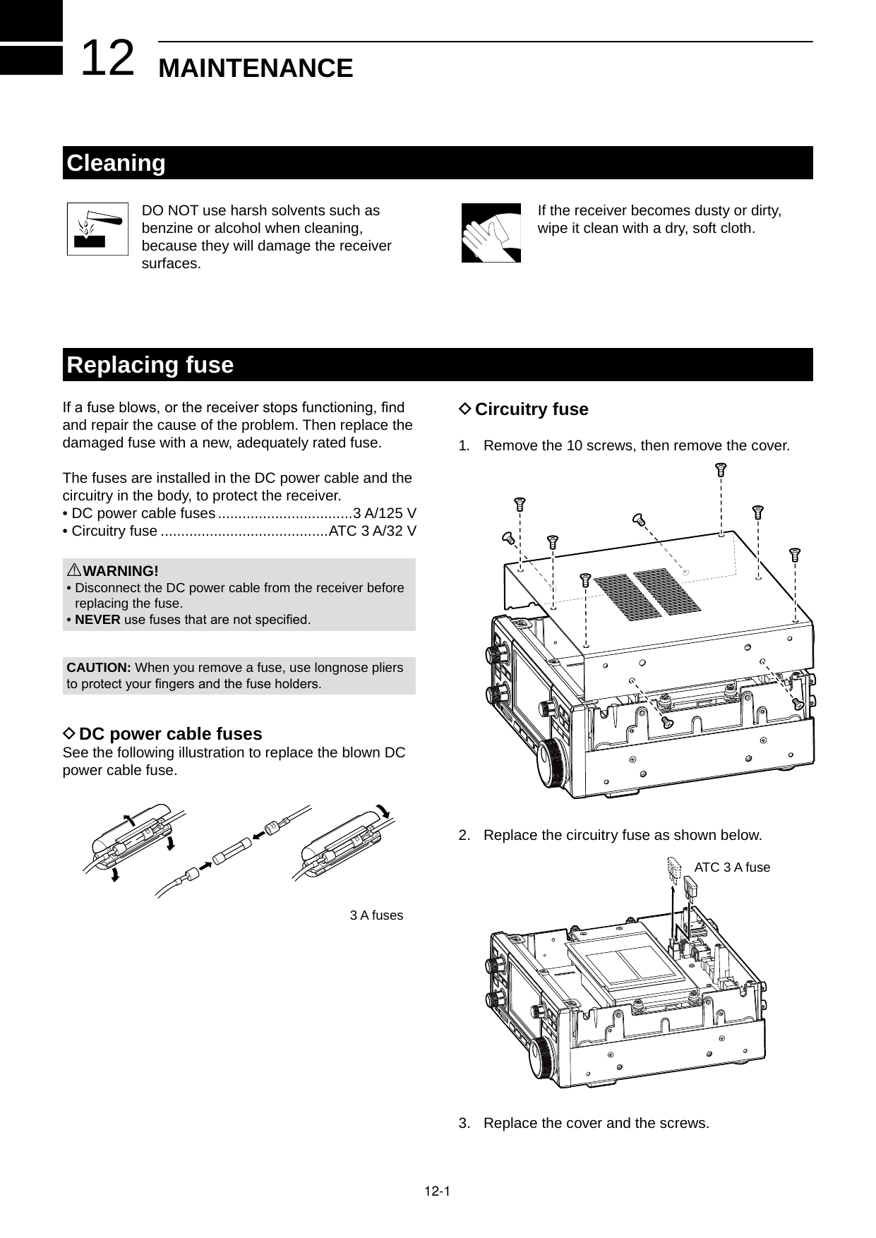
![12-2ResettingOccasionally, erroneous information may be displayed. This may be caused by static electricity or by other factors.If this problem occurs, turn OFF the receiver. After waiting a few seconds, turn ON the receiver.If the problem still exists, perform a Partial reset as described below.If the problem still exists after a Partial reset, perform an All reset as described to the right.NOTE: An All reset clears all data and returns all settings to their factory defaults. Save memory channel content, setting status, and so on, onto an SD card before doing an All reset. (p. 7-2) DPartial resetA Partial reset resets operating settings to their default values (Timer setting, NTP Server Address, Lower and upper edge of the spectrum scope, Set mode items).L Network settings, Reference frequency, Memory channels and Opening comments are not returned to their default value.1. Open the RESET screen.MENU » SET > Others > Reset2. Touch “Partial reset.” • The conrmation screen is displayed. 3. Touch [Yes]. L After resetting, the IC-R8600 will automatically restart. DAll resetAll reset clears all data and returns all settings to their factory defaults.1. Open the RESET screen.MENU » SET > Others > Reset2. Touch “All reset.” • The conrmation screen is displayed. 3. Touch [NEXT]. 4. After carefully reading the displayed message, touch [YES] to perform the All reset.L After resetting, the IC-R8600 will automatically restart. TIP: When you cannot operate the screenIf a touch screen operation error or an unexpected operation occurs, you cannot enter the Set mode. In that case, perform the All reset as described below:1. Turn OFF the receiver power.2. While holding down and , push . • "ALL RESET" is displayed on the opening screen.L If "ALL RESET" is not displayed, repeat the above procedure again.12MAINTENANCE123456789101112131415161718192021](https://usermanual.wiki/ICOM-orporated/381801/User-Guide-3440284-Page-79.png)
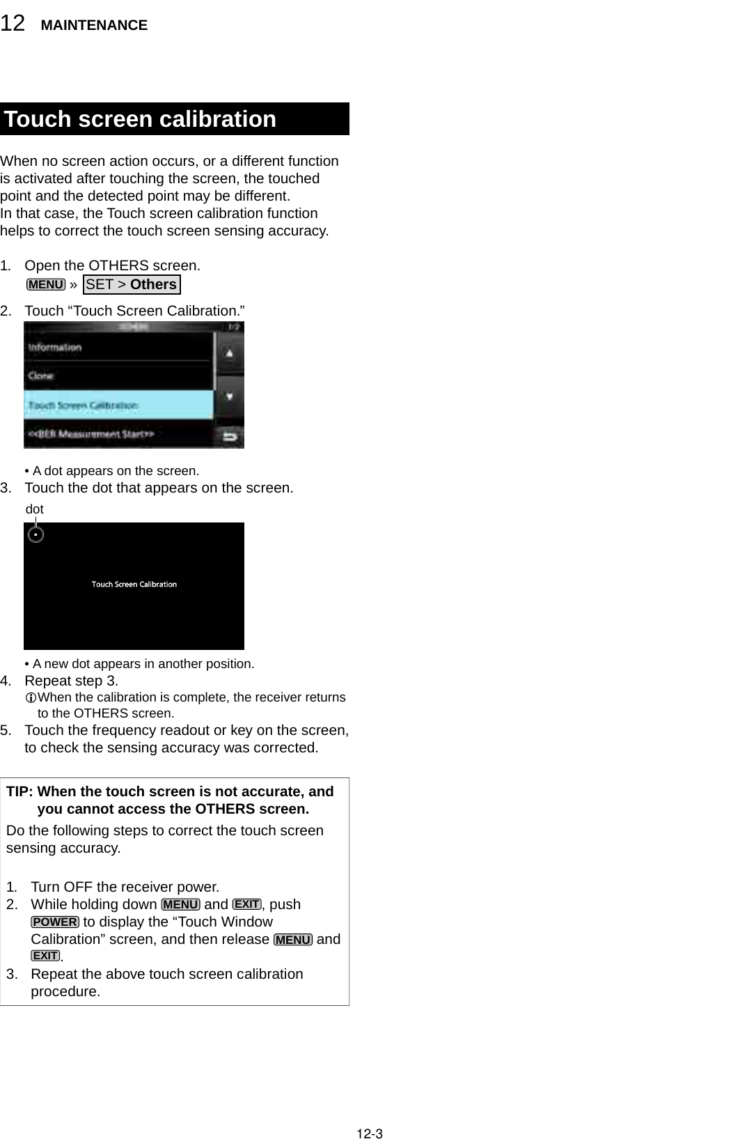
![12-4TroubleshootingThe following chart is designed to help you correct problems which are not equipment malfunctions.If you are unable to locate the cause of a problem, or solve it through the use of this chart, contact your nearest Icom Dealer or Service Center.PROBLEM POSSIBLE CAUSE SOLUTION REF.Power does not come on when is pushed.Power cable is improperly connected. Reconnect the power cable correctly. p. 2-1 The external power supply is turned OFF. Turn ON the external power supply. p. 2-1The DC power cable fuses or circuitry fuse is blown. Find and repair the cause of the problem and then replace the damaged fuse with a new one.p. 12-1The optional AD-55NS or SP-39AD is used but the supplied short connector is not connected.Connect the supplied DC power short connector to [DC 13.8 V]. p. 2-1No sound is heard from the speaker. Audio level is too low or 0%. Set the audio level to a higher level. p. 3-1The squelch is too tight. Set the squelch level to open the squelch. p. 3-1The Tone/Code squelch or Digital squelch (D.SQL) is ON. Turn OFF the Tone or Digital squelch. p. 5-9A headphones is connected to [EX-SP] or [PHONES]. Disconnect the headphones. p. 2-3The external speaker cable is disconnected. Check the external speaker cable and repair it. p. 2-3Sensitivity is too low, and only strong signals can be heard.The attenuator is activated. Turn OFF the attenuator in the FUNCTION screen. p. 5-1The RF gain is reduced. ("RFG" is displayed.) Set [RF GAIN] to 100%. ("RFG" is disappeared.) p. 3-1The antenna is defective or the coaxial cable is shorted or disconnected.Repair the problem and then reconnect to the antenna connector. p. 2-2You are using an antenna not suitable for the band you have selected. Connect an antenna suitable for the operating frequency. p. 2-2The selected antenna connector is incorrect. Select the appropriate antenna connector. pp. 2-2, 3-2 or 5-1The squelch is too tight. Set the squelch level to open the squelch. p. 3-1Received audio in the SSB mode is unclear or distorted.The incorrect sideband is selected. Toggle between USB and LSB. p. 3-1The Digital TWIN PBT function is activated. Touch [PBT1] or [PBT2] for 1 second to clear the settings. p. 5-2The displayed frequency does not properly change by rotating .The Dial Lock function is activated. (The [LOCK] indicator lights.) Hold down for 1 second to turn OFF the Lock function.p. 3-312MAINTENANCE123456789101112131415161718192021](https://usermanual.wiki/ICOM-orporated/381801/User-Guide-3440284-Page-81.png)
![12-5MAINTENANCE12Troubleshooting (Continued)PROBLEM POSSIBLE CAUSE SOLUTION REF.The backlight is OFF. The indicator lights. (The Panel Lock function is activated.) Push to turn OFF the Panel Lock function.p. 3-3The touch panel does not work.Programmed scan does not start. The same frequencies have been set in scan edge memory channels. Set different frequencies in scan edge memory channels (P00A/P00B ~ P49A/P49B).p. 8-2Memory scan does not start. There is no entered memory channel. Enter at least 2 memory channels. p. 8-2In the Memory mode, "BLANK" is displayed instead of frequency. Write a frequency to the blank channel. p. 8-2Select memory scan does not start. 0 or only 1 memory channel is assigned as a Select channel. Assign at least 2 memory channels as Select channels. p. 9-8Cannot hear the speech after pushing .The speech level is too low. Adjust the speech level in the Set mode. p. 11-3The frequency readout is blinking. No external reference signal is input. Check the [REF I/O 10MHz] connector setting or external signal source. p. 11-7“OVF” is displayed. An excessively strong signal is received. Set [RF GAIN] to a lower level. p. 3-1Turn OFF the Preamp. p. 5-1Turn ON the attenuator. p. 5-1The touch screen is not correctly working. The touched point and the detected point may be different. Calibrate the touch screen. p. 12-3Spectrum scope's sensitivity is too low, and only strong signals are displayed.The reference level is too low. Set the reference level to a higher level. p. 4-4When selecting a rmware le, "- No File -" is displayed.No rmware le is not found on the SD card.Copy the rmware le to the SD card. p. 13-2The inserted SD card is not formatted. Format the SD card with the built-in format function. p. 7-2The rmware le name has been changed.Download the rmware again. p. 13-1FSK (RTTY) signal is not demodulated. The Mark or Space frequency is incorrect. Set the appropriate Mark and Space frequencies. p. 5-7FSK (RTTY) signal is received but not decoded.The shift setting is reversed. Select the FSK-R (Reverse) mode. p. 3-1](https://usermanual.wiki/ICOM-orporated/381801/User-Guide-3440284-Page-82.png)
![13-1 General Preparation D About updating the fi rmwareYou can update the IC-R8600’s fi rmware using an SD card. Updating the fi rmware may add new functions and improves performance parameters.You can download the latest fi rmware from the Icom website.http://www.icom.co.jp/world/index.html D Checking the fi rmware versionYou can check the fi rmware version on the Opening screen when you turn ON the receiver.TIP: You can also check the fi rmware version on the INFORMATION screen.MENU » SET > Others > Information > VersionThe Main CPU's fi rmware version is displayed. D Downloading the fi rmware fi leAccess the following URL and download the firmware file.http://www.icom.co.jp/world/index.html These instructions are based on Microsoft® Windows® 7.1. Click [Support].2. C l i c k “Firmware Updates/Software Downloads”.3. Click the desired firmware file link.4. Read “Regarding this Download Service” carefully, and then click [Agree].5. Click “Save as” in the displayed File Download dialog.6. Select the location where you want to save the firmware, and then click [Save] in the displayed File Download dialog. • The fi le starts downloading. • The fi rmware and the fi rm utility are compressed in a “zip” format folder. Unzip it before use. D Unzipping the fi rmware folder1. Right-click the downloaded firmware folder (zip format). • Right-click menu is displayed.2. Click “Extract All...” • After unzipping, a folder is created in the same locationas the downloaded folder. In the “R8600_X*” folder, “8600XXXX.dat*” is created.* X represents the release number.13UPDATING THE FIRMWARE123456789101112131415161718192021](https://usermanual.wiki/ICOM-orporated/381801/User-Guide-3440284-Page-83.png)
![13-2UPDATING THE FIRMWARE13 Updating the fi rmwareIMPORTANT: To update the fi rmware, fi rst format your SD card using the IC-R8600. (p. 7-2) Then copy the downloaded fi rmware data from your PC into the IC-R8600 folder that was created on the SD card.CAUTION: NEVER turn OFF the receiver while updating the fi rmware.If you turn OFF the receiver, or if a power failure occurs while updating, the fi rmware will be damaged and you will have to send the receiver back to the nearest Icom distributor for repair. This type of repair is out of warranty, even if the receiver warranty period is still valid.TIP: BE SURE to unzip the downloaded fi le. See “Unzipping the fi rmware fi le (p. 13-1)” for details.1. Copy the downloaded firmware data into the IC-R8600 folder on the SD card.2. Insert the SD card into the receiver's [SD CARD] slot.3. On the Set mode menu screen, display the SD CARD screen.MENU » SET > SD card4. Select “Firmware Update.” The Firmware Update Agreement screenCopyTIP: To check the fi rmware version after the updating, see “Checking the fi rmware version (p. 13-1)” for details.5. Touch [Ù] or [Ú] to scroll the screen. Carefully read all the displayed precautions.6. After you read and agree with all the precautions, touch [YES]. • The fi le select screen is displayed.If you want to cancel the updating, touch [NO].7. Touch the Firmware (Example: 8600XXXX.dat*). • The fi nal confi rmation screen is displayed. Carefully read all the displayed precautions. * X represents the release number.8. After you read and agree with all the precautions, touch [YES] for 1 second. • The updating starts.If you want to cancel the updating, touch [NO].9. “Firmware updating has completed.” is displayed in the dialog. • The IC-R8600 will automatically restart. After the updating fi nishes, the operating screen is displayed.](https://usermanual.wiki/ICOM-orporated/381801/User-Guide-3440284-Page-84.png)
![14-1 DGeneral • Frequency coverage: USA 0.010000 ~ 821.999999 MHz* 851.000000 ~ 866.999999 MHz 896.000000 ~ 3000.000000 MHz France 0.135700 ~ 0.137800 MHz 1.810000 ~ 1.850000 MHz 3.500000 ~ 3.800000 MHz 7.000000 ~ 7.200000 MHz 10.100000 ~ 10.150000 MHz 14.000000 ~ 14.350000 MHz 18.068000 ~ 18.168000 MHz 21.000000 ~ 21.450000 MHz 24.890000 ~ 24.990000 MHz 28.000000 ~ 29.700000 MHz 50.000000 ~ 52.000000 MHz 144.000000 ~ 146.000000 MHz 430.000000 ~ 440.000000 MHz 1240.000000 ~ 1300.000000 MHz 2300.000000 ~ 2450.000000 MHz Other than above 0.010000 ~ 3000.000000 MHz* *Some frequency ranges are not guaranteed. • Receiving modes: SSB, CW, FSK, AM, FM, WFM and DIGITAL ( D-STAR, P25, NXDN, dPMR and DCR) • Number of memory channels: 2000 (in 100 groups) + 400 (Scan edges: 100 (50 pairs), Auto Memory Write: 200 and Scan Skip: 100) • Power supply requirement: 13.8 V DC (±15%) • Grounding system: Negative • Operating temperature range: –10°C to +60°C, +14°F to +140°F • Frequency stability: Less than ±0.5 ppm • Antenna connectors: • Frequency resolution: 1 Hz (minimum) • Power consumption: Standby 1.8 A Maximum audio 2.0 A • Dimensions (projections not included): 220 (W)×90 (H)×230 (D) mm, 8.7 (W)×3.5 (H)×9.1 (D) in • Weight (approximately): 4.3 kg, 9.5 Ib DReceiver • Receive system: 0.010000 ~ 29.999999 MHz Direct sampling 30.000000 ~ 1099.999999 MHz Double superheterodyne 1100.000000 ~ 3000.000000 MHz Triple superheterodyne • Sampling frequency: 122.88 MHz • Intermediate frequencies: [ANT1] [ANT2] [ANT3]Frequency range 10 kHz ~ 3000 MHz 10 kHz ~ 30 MHz 10 kHz ~ 30 MHzImpedance 50 Ω Unbalanced 50 Ω Unbalanced 500 Ω UnbalancedConnector N type SO-239 RCAReceive frequency (MHz) 1st IF (MHz) 2nd IF (MHz) 3rd IF (MHz) 0.010000 ~ 29.999999 – – – 30.000000 ~ 499.999999 778.7 46.35 – 500.000000 ~ 1099.999999 278.7 46.35 – 1100.000000 ~ 1499.999999900 ~ 500.00001278.7 46.35 1500.000000 ~ 3000.000000 1000 ~ 500 278.7 46.3514SPECIFICATIONS123456789101112131415161718192021](https://usermanual.wiki/ICOM-orporated/381801/User-Guide-3440284-Page-85.png)
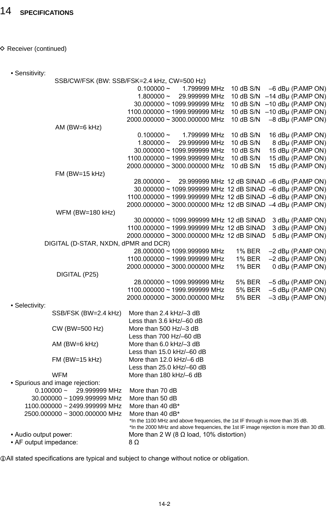
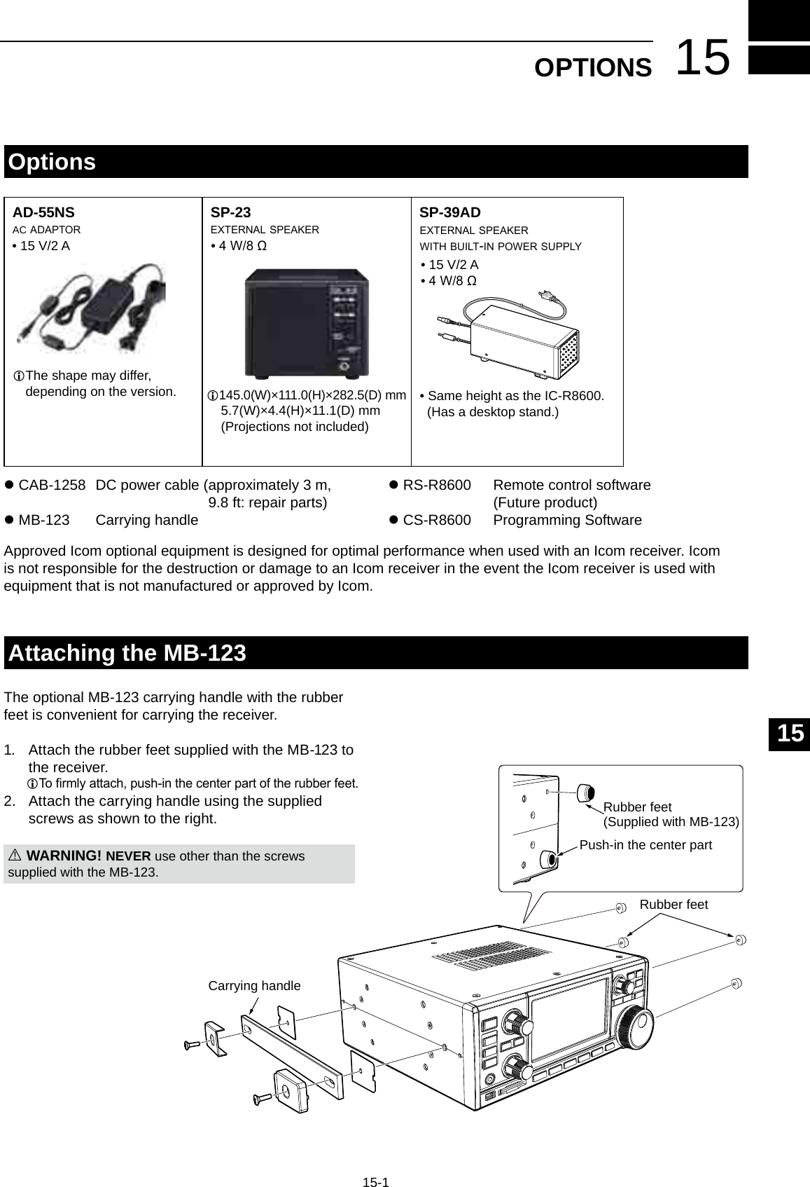
![16-1[10.7 MHz OUT]Outputs the 10.7 MHz IF signal for an external detector/demodulator circuit. • Center frequency: 10.7 MHz • Band width*: 10 MHz • Impedance:50 Ω (unbalanced) • Maximum output level:-10dBm (approximately)*The band width is xed regardless of the digital PBT lter setting.[REF I/O 10 MHz]Outputs or inputs a 10 MHz reference frequency signal.You can change the signal direction in the Set mode. • Center frequency:10 MHz • Impedance: 50 Ω (unbalanced) • Input/Output level: –10 dBm (approximately) • Frequency stability: ±0.5 ppm (–10°C ~ +60°C, +14°F ~ +140 °F)[I/Q OUT]Outputs the Phase/Quadrature data which is processed by the FPGA.Connect a PC's USB port, to demodulate the DRM broadcast or Software Dened Radio SDR. • Interface: USB (1.1/2.0), type BL Icom does not provide any support regarding SDR technology and related software, except the inspection for the normality of output signal.L The IQ driver and instruction guide will be released on the Icom website near future. http://www.icom.co.jp/world/index.html[AF/IF]Outputs the demodulate audio signal or 12 kHz IF signal (unltered). The output level is xed, regardless of the volume control position. (3.5 mm, 1/8 in (d)) • Impedance: 4.7 kΩ • Output level: 100 ~ 300 mV (RMS)LYou can select the output signal from AF or IF signals. MENU » SET > Connectors > AF/IFLThe signal is also output from [USB] (front or rear) or [LAN].[USB]2 USB ports: Type B mini and Type B.L You can download the USB driver and installation guide from the Icom website. http://www.icom.co.jp/world/support/download/rm • Outputs the decoded FSK (RTTY) signal, or D-STAR data. • Outputs the demodulated signal or 12 kHz IF signal. • Remote control interface for optional RS-R8600 (feature product). • Programming interface for the optional CS-R8600.L You can change the port settings (FSK decode data/D-STAR data, AF/IF), baud rate and output level)MENU » SET > Connectors > USB (Front)MENU » SET > Connectors > USB (Rear)[LAN]LED indication:qLINK/ACT Lights: Cable connected. Doesn't light: Cable not connected. Blinks: While the line is communicating.wSpeed Lights: Communicating in 100BASE-TX Doesn't lights: Communicating. in10BASE-T, or not connected. • Time synchronization by an NTP server. • Outputs the demodulated signal or 12 kHz IF signal. • Remote control interface for the optional RS-R8600 (future product).LYou can select the output signal from AF and IF signals.MENU » SET > Connectors > LAN[MUTE] JACK / [MUTE] SWITCHUsed to mute the receiver output.(3.5 mm, 1/8 in (d))When the Mute Switch is slid to right, the receiver enters to the Bit Error Rate (BER) Measurement mode for the maintenance purpose.When the [MUTE] is slid to left:When this terminal is grounded, the receive circuit is turned OFF. L Use this function when you use the IC-R8600 with a transceiver.LThe sink current is approximately 1 mA at 8 V input.When the [MUTE] is slid to right:Connect a BER counter. In the BER Measurement mode, the PN9 bit stream is output from this terminal.[METER]Connects to an external meter.Outputs the received signal strength or squelch level.(3.5 mm, 1/8 in (d)) • Output voltage: 8 V (maximum) • Output impedance: 10 kΩL You can select the output signal from received signal strength and squelch levels. MENU » SET > Connectors q w+_16 CONNECTOR INFORMATIONBNC typeBNC typeOn the front panelminiB type B typeOn the rear panelMeter outputMute](https://usermanual.wiki/ICOM-orporated/381801/User-Guide-3440284-Page-88.png)
![16-2[REMOTE]Used to remotely controls the receiver with the CI-V format data.(3.5 mm, 1/8 in (d))L You can download the USB driver and installation guide from the Icom website. http://www.icom.co.jp/world/support/download/rmIn the remote control mode, push [LOCAL] to return to the normal (Local) mode (LOCAL LED turns OFF).*Except , and .Remote connection example with a PC[EXT-SP]Connects to an external speaker such as the optional SP-39AD. (3.5 mm, 1/8 in (d)) • Output impedance: 4 ~ 8 Ω • Output level: More than 2 W at 10% distortion into an 8 Ω load.[DC IN]Connects to the optional SP-39AD.When SP-39AD or AD-55NS is connected, connect the supplied DC short connector to [DC13.8V].[DC13.8V]Accepts the regulated DC power for 13.8 V DC (±15%), through the supplied DC power cable. WARNING! NEVER reverse the DC power cable polarity (Red= , Black= ).[ANT 1] • Frequency range: 10 kHz ~ 3000 MHz • Input impedance: 50 Ω (unbalanced)L When the receive frequency is set to between 10 kHz and 29.999999 MHz, you can select the antenna on [ANT 1] ~ [ANT 3]. (p. 3-3)[ANT 2] • Frequency range: 10 kHz ~ 30 MHz • Input impedance: 50 Ω (unbalanced)[ANT 3]LFor a long wire antenna. • Frequency range: 10 kHz ~ 30 MHz • Input impedance: 400 ~ 500 Ω (unbalanced)[AUX]A reserved terminal. No internal connection. [PHONES]Connects to standard stereo headphones. (3.5 mm, 1/8 in (d)) • Output impedance: 8 ~ 16 Ω • Output level: More than 50 mW (into an 8 Ω load)SO-239IC-R8600USB cable (A-B type)PC16CONNECTOR INFORMATION123456789101112131415161718192021View from the rearN typeRCA typeRCA type](https://usermanual.wiki/ICOM-orporated/381801/User-Guide-3440284-Page-89.png)
![INDEX123456789101112131415161718192021IIIISymbols∂F scan ..................................................................9-5∂F scan operation ..................................................9-5[NOTCH] Switch ...................................................11-3[P.LOCK] Switch ...................................................11-3[SPEECH/LOCK] Switch ......................................11-3Number2nd DNS Server (Valid after Restart) ...................11-7AAuto Tuning Step function ......................................3-3ABOUT THE INSTRUCTIONS ................................. ivAbout the VFO and Memory modes .......................3-1AF Beep/Speech... Output...........................11-5, 11-6AFC function ...........................................................5-5AFC Limit ..............................................................11-3AF Output Level....................................................11-5AF Speech Output ................................................11-6AF SQL ........................................................11-5, 11-6AGC function ..........................................................5-1AGC Time constant ................................................5-1Antenna About antenna ............................................ 2-2, 3-3 Connecting an antenna ......................................2-2 Antenna connectors ............................... 14-1, 16-2 Selecting the antenna ................................ 3-3, 5-1Attenuator ...............................................................5-1Audio Audio tone ..........................................................3-1 Bass .................................................................11-2 De-Emphasis ....................................................11-2 HPF/LPF ..........................................................11-2 Tone Control .....................................................11-2 Treble ...............................................................11-2 Volume level .......................................................3-1Audio Port (UDP) ..................................................11-8Auto Memory Write scan ........................................9-6BBacklight dimmer ....................................................3-4Beep (Conrmation) .............................................11-2 Beep Level .......................................................11-2 Beep Level Limit ...............................................11-2BER Measurement .............................................11-10BW Popup (FILTER) .............................................11-9BW Popup (PBT) ..................................................11-9CCC ........................................................................5-10CI-V Address ............................................................11-6 Baud Rate ........................................................11-6 Baud Rate (Front USB port) ............................11-6 Baud Rate (Rear USB port) ............................11-7 Echo Back (Front USB port) ............................11-6 Echo Back (Rear USB port) ............................11-7 Port (Rear USB port) .......................................11-7 Transceive ........................................................11-6Cleaning ...............................................................12-1Clock NTP Function .................................................11-10 NTP Server address .......................................11-10 NTP Server address setting .............................10-1 NTP TIME .......................................................11-10 NTP Time Server ..............................................10-1 Setting date and time .......................................10-1 Time Set .........................................................11-10 Time synchronization .......................................10-1 UTC Offset .....................................................11-10Clone Mode ........................................................11-10COM ID (Common ID) ..........................................5-10CONNECTOR INFORMATION ............................16-1Connectors ...........................................................11-5Control Port (UDP) (Valid after Restart) ...............11-8Copying the Memory contents ................................8-3CW CW .....................................................................5-5 Normal Side .....................................................11-3 Reversing the carrier point .................................5-5DDaily timer .............................................................10-2Date ...........................................................11-4, 11-10DC power supply ....................................................2-1Decoding FSK signal ..............................................5-5Decryption function ...............................................5-10De-Emphasis ........................................................11-2Default Gateway (Valid after Restart) ...................11-7Descrambler function............................................5-10DHCP (Valid after Restart) ...................................11-7DIAL A .....................................................................1-2DIAL B ....................................................................1-1DIAL C ....................................................................1-2Dial Lock function ...................................................3-3Dial/Panel Lock function .........................................3-3Digital Code Squelch ..............................................5-9Digital IF lter..........................................................5-3Digital Mode Select...............................................11-4Digital Monitor.......................................................11-4Digital Set .............................................................11-4Digital Squelch........................................................5-9Digital Twin PBT .....................................................5-2Directly entering a frequency ..................................3-2Display Type .........................................................11-9](https://usermanual.wiki/ICOM-orporated/381801/User-Guide-3440284-Page-91.png)
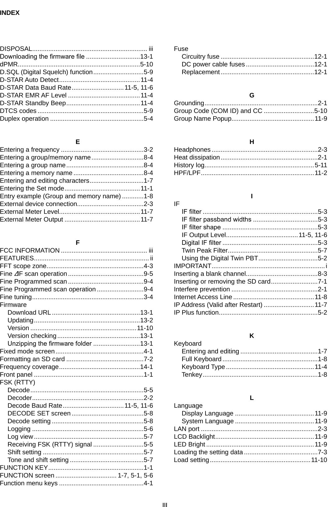
![INDEXVV Playing back .......................................................6-1 Playing back on a PC .........................................6-2 Quick recording ..................................................6-1 Recording setting ...............................................6-1 RECORDER SET screen ...................................6-4REF (reference frequency) adjust ........................11-4Reference level.......................................................4-4REF IN/OUT .........................................................11-7Reset All reset .................................................11-10, 12-2 Partial reset ...........................................11-10, 12-2Reversing the carrier point .....................................5-5RF gain ...................................................................3-1RX history items ...................................................5-11RX History Log .....................................................11-4RX Marker ..............................................................4-1RX Popup .............................................................11-9RX Record (D-STAR RPT) ...................................11-4SSave Setting .......................................................11-10Saving data onto the SD card.................................7-1Saving in the old format ..........................................7-2Saving the setting data ...........................................7-2Scan delay timer .....................................................9-2Scan ∂F scan ..............................................................9-5 Basic scanning ...................................................9-1 Fine ∂F scan operation ......................................9-5 Fine Programmed scan ......................................9-4 Fine Programmed scan operation ......................9-4 Memory scan and Select Memory scan .............9-7 Memory scan operation ......................................9-7 Mode select memory scan .................................9-9 Scan Resume function .......................................9-2 Scan delay timer ................................................9-2 Scan Setting screen ...........................................9-3 SCAN SPEECH (at Receive Pause) ................ 11-2 Scan speed ........................................................9-1 Scan types .........................................................9-1 Select Memory channel ......................................9-7 Select Memory channel settings ........................9-8 Select Memory channel clearing ........................9-8 Select Memory channel setting ..........................9-8 Skip frequency ...................................................9-9 Temporary Skip ................................................9-10 Tone scan operation .........................................9-11 Programmed scan ..............................................9-4 VFO scan and Memory scan ..............................9-1Spectrum scope Center mode screen ...........................................4-1 Reference level ..................................................4-4 Scope screen .....................................................4-1 Scope screen parameters ..................................4-5 Scope set screen ...............................................4-5 Waterfall zone ....................................................4-3Screen Screen Capture File Type ................................11-4 Screen Capture function ..................................5-11 Screen Capture [POWER] Switch .................... 11-3 Screen Capture View .....................................11-10 Screen Saver ...................................................11-9 Touch screen calibration ..................................12-3SD card...............................................................11-10 Audio le delete ..................................................6-3 Audio le folder delete ........................................6-4 Audio le information ..........................................6-3 Checking SD card information ...........................7-3 Checking the le information ..............................6-3 Formatting an SD card .......................................7-2 Inserting or removing .........................................7-1 Loading the data les .........................................7-3 SD card compatibility .........................................7-1 SD card data ......................................................7-1 SD card deleting a data le ................................7-3 SD card deleting a folder ....................................6-4 SD Card Info ..................................................11-10 SD card information ...........................................7-3 SD card loading data les ..................................7-3 SD card removal ................................................7-1 SD card saving setting data ...............................7-2 SD card’s folder contents ...................................7-1 Saving data onto the SD card ............................7-1 Saving in the old format .....................................7-2 Saving the setting data .......................................7-2Searching for the peak signal .................................4-3Search menu keys ..................................................4-3Select Memory channel ..........................................9-7Select Memory channel clearing ............................9-8Select Memory channel setting ..............................9-8Select Memory scan operation ...............................9-7Sensitivity .............................................................14-1Separator/Decimal ................................................11-4Serial Function.............................................11-5, 11-6Serial Port (UDP) (Valid after Restart) ..................11-8Set mode description ............................................11-1Setting time...........................................................10-1Skip channel for memory scan .............................9-10Skip frequency ........................................................9-9Sleep timer ...........................................................10-2S-Level SPEECH..................................................11-2Specication .........................................................14-1Spectrum Scope Fixed mode screen .............................................4-1 Mini scope screen ..............................................4-3 Peak signal .........................................................4-3 Range .................................................................4-2 Span ...................................................................4-2 Spectrum scope screen .....................................4-1 Sweep speed .....................................................4-4](https://usermanual.wiki/ICOM-orporated/381801/User-Guide-3440284-Page-94.png)