ICOM orporated 381801 381801-01 User Manual
ICOM Incorporated 381801-01
User Manual
INSTRUCTION MANUAL
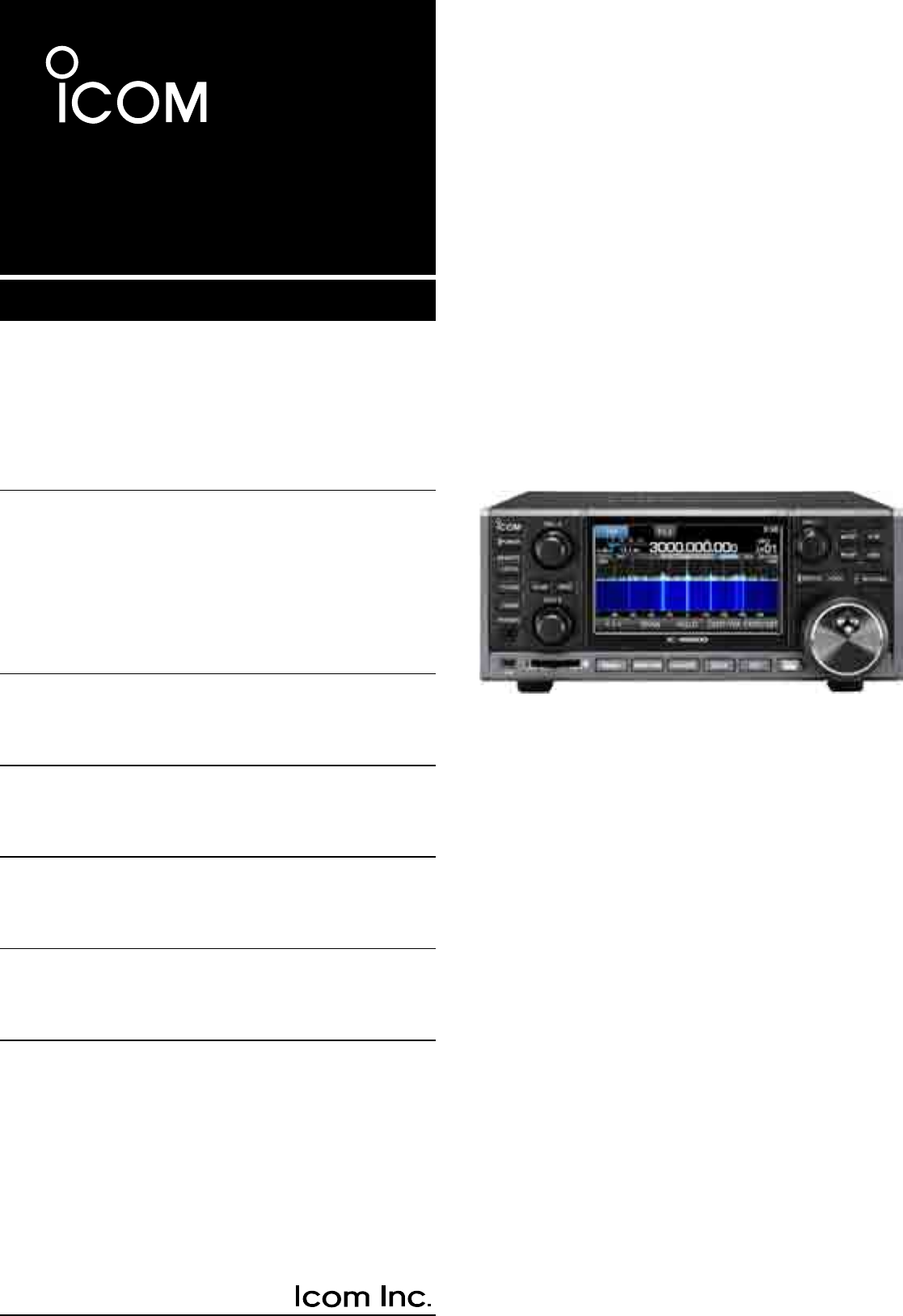
iR8600
COMMUNICATIONS RECEIVER

i
WORD DEFINITION
R DANGER! Personal death, serious injury or an
explosion may occur.
R WARNING! Personal injury, fire hazard or electric
shock may occur.
CAUTION Equipment damage may occur.
NOTE Recommended for optimum use. No
risk of personal injury, fire or electric
shock.
EXPLICIT DEFINITIONS
IMPORTANT
READ ALL INSTRUCTIONS carefully completely
before using the receiver.
SAVE THIS INSTRUCTION MANUAL— This
instruction manual contains operating instructions for
the IC-R8600
.
PREFACE
Thank you for choosing this Icom product. The IC-
R8600 COMMUNICATIONS RECEIVER is a wide band
receiver which designed to cover the 10 kHz to
3 GHz range with Icom’s state of the SDR technology.
With proper care, this product should provide you
with years of trouble-free operation. Many hours of
research and development went into the design of
your IC-R8600.
This product includes RTOS “RTX” software, and is licensed according to the software license.
This product includes “zlib” open source software, and is licensed according to the open source software license.
This product includes “libpng” open source software, and is licensed according to the open source software license.
Refer to page I for information on the open source software being used by this product.
TRADEMARKS
Icom, Icom Inc. and the Icom logo are registered trademarks of Icom Incorporated (Japan) in Japan, the United States, the
United Kingdom, Germany, France, Spain, Russia, Australia, New Zealand and/or other countries.
NXDN is a trademark of Icom Incorporated and JVC KENWOOD Corporation.
dPMR and the dPMR logo are trademarks of the dPMR MoU Association.
Microsoft, Windows and Windows Vista are registered trademarks of Microsoft Corporation in the United States and/or other
countries.
All other products or brands are registered trademarks or trademarks of their respective holders.
ii
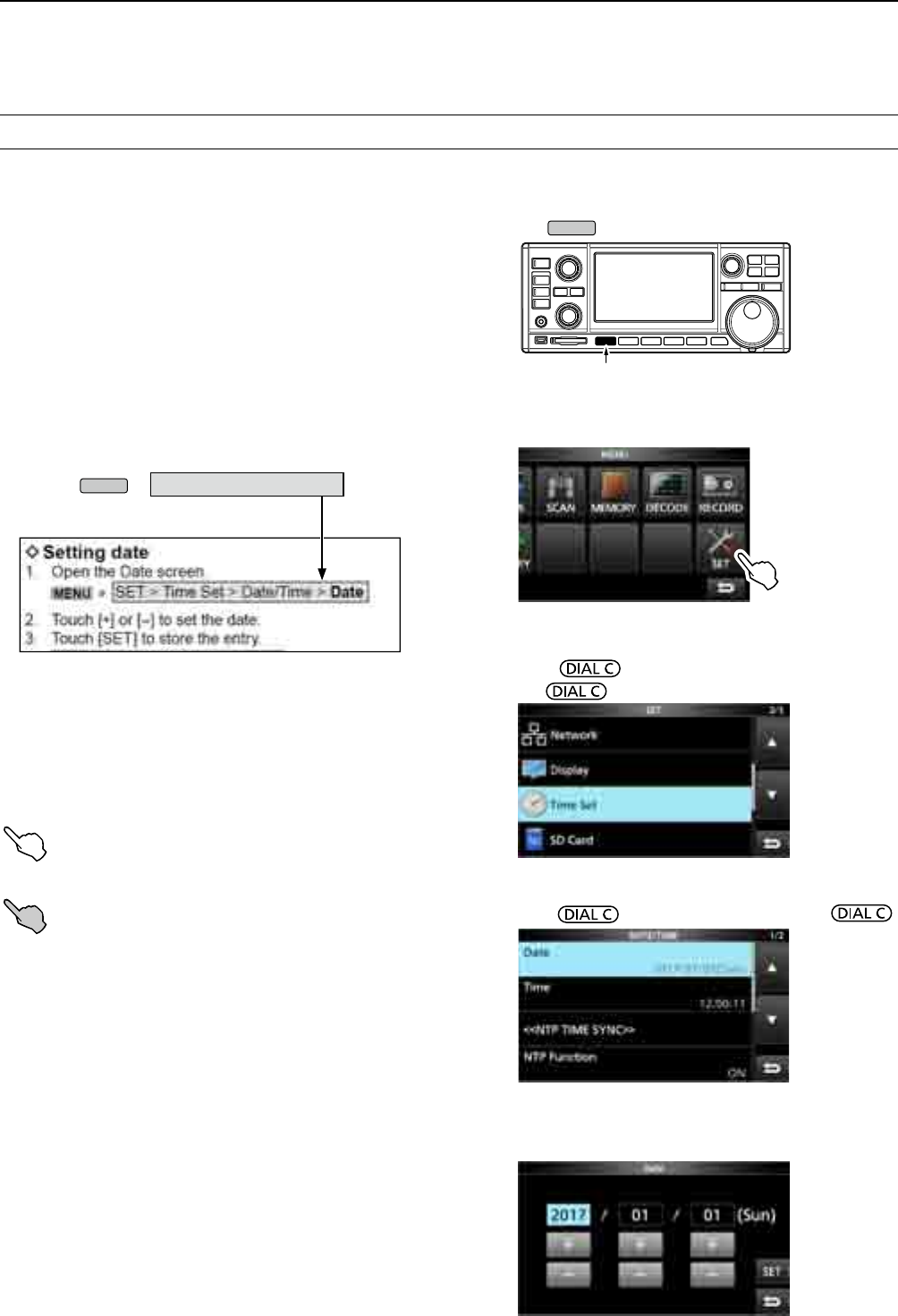
While ordinary wide band receivers need to have dedicated demodulator circuits for each receive mode, the IC-
R8600 utilizes advanced digital processes that demodulate the incoming signals.
The IF signal is sent to the A/D converter, resulting in digital signal, then is processed by a high-speed FPGA and
DSP to be restored to an analog audio signal.
The received signal is processed to be demodulated according to the receive mode, including not only conventional
analog communications in CW, AM, SSB, FM, WFM and FSK, but also advanced digital communications in D-STAR,
P25, NXDN, dPMR and DCR. This was archived by using Software Dened Radio (SDR) technology.
The AMBE+2™ voice coding Technology embodied in this product is protected by intellectual property rights
including patent rights, copyrights and trade secrets of Digital Voice Systems, Inc. This voice coding Technology is
licensed solely for use within this Communications Equipment. The user of this Technology is explicitly prohibited
from attempting to extract, remove, decompile, reverse engineer, or disassemble the Object Code, or in any other
way convert the Object Code into a human-readable form. U.S. Patent Nos.
#5,870,405, #5,826,222, #5,754,974, #5,701,390, #5,715,365, #5,649,050, #5,630,011, #5,581,656, #5,517,511,
#5,491,772, #5,247,579, #5,226,084 and #5,195,166.
FEATURES
•Covers 10 kHz to 3 GHz for wide band reception
• Receives various digital modes such as
D-STAR, P25 (Phase 1), NXDN, dPMR and DCR
(Digital Convenience Radio)
•12 kHz IF output port for DRM broadcast
•Hi-speed Real-Time Spectrum Scope
•A 4.3 inch touch panel color display
•Multi-function dials for easy settings
•An SD card slot
You can record the received audio, save the receiver
settings, decoded FSK logs and so on, onto an SD card
(user supplied).
•“IP+” Function
The IP Plus function improves 3rd order intercept point
(IP3) performance.
•I/Q baseband signal output port
• Optional external speaker (with integrated power
supply)
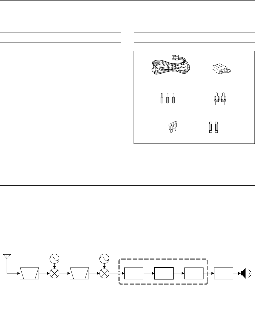
SUPPLIED ACCESSORIES
ABOUT THE SDR WIDEBAND RECEIVER CIRCUITS
VOICE CODING TECHNOLOGY
L Different types of accessories may be supplied, or may
not be supplied depending on the receiver version.
DC power cable
(3 m: 9.8 ft)
Spare fuse
(3 A/32 V) Spare fuse
(3 A/125 V)
Speaker plugs
(3.5 mm: 1/8" Stereo) RCA plugs
DC power short connector
FPGA
BPF BPF A/D DSP D/A
1st LO 2nd LO
IF
Demodulator
Double conversion super heterodyne receiver (Example for 30.000000 MHz ~ 1099.999999 MHz)

iii
•FOR CLASS B UNINTENTIONAL RADIATORS:
This equipment has been tested and found to comply
with the limits for a Class B digital device, pursuant
to part 15 of the FCC Rules. These limits are
designed to provide reasonable protection against
harmful interference in a residential installation. This
equipment generates, uses and can radiate radio
frequency energy and, if not installed and used in
accordance with the instructions, may cause harmful
interference to radio communications. However, there
is no guarantee that interference will not occur in a
particular installation. If this equipment does cause
harmful interference to radio or television reception,
which can be determined by turning the equipment
off and on, the user is encouraged to try to correct
the interference by one or more of the following
measures:
• Reorient or relocate the receiving antenna.
• Increase the separation between the equipment
and receiver.
• Connect the equipment into an outlet on a
circuit different from that to which the receiver is
connected.
• Consult the dealer or an experienced radio/TV
technician for help.
DISPOSAL
The crossed-out wheeled-bin symbol on your product, literature, or packaging reminds you that in
the European Union, all electrical and electronic products, batteries, and accumulators
(rechargeable batteries) must be taken to designated collection locations at the end of their work-
ing life. Do not dispose of these products as unsorted municipal waste.
Dispose of them according to the laws in your area.
FCC INFORMATION
WARNING: MODIFICATION OF THIS DEVICE
TO RECEIVE CELLULAR RADIOTELEPHONE
SERVICE SIGNALS IS PROHIBITED UNDER FCC
RULES AND FEDERAL LAW.
CAUTION: Changes or modications to this device,
not expressly approved by Icom Inc., could void
your authority to operate this device under FCC
regulations.
Icom is not responsible for the destruction, damage to, or performance of any Icom or non-Icom equipment, if the
malfunction is because of:
• Force majeure, including, but not limited to, res, earthquakes, storms, oods, lightning, or other natural
disasters, disturbances, riots, war, or radioactive contamination.
• The use of Icom receivers with any equipment that is not manufactured or approved by Icom.
iv
DAbout the touch operation
In the manual, the touch operation is described as
shown below.
Touch
If the display is touched briey, one short beep
sounds.
Touch for 1 second
If the display is touched for 1 second, one
short and one long beep sound.
DTouch screen precautions
• The touch screen may not properly work when the
LCD protection lm or sheet is attached.
• Touching the screen with your nger nails, sharp
topped object and so on, or touching the screen
hard may damage it.
• Tablet PC’s operations such as ick, pinch in and
pinch out cannot be performed on this touch screen.
DTouch screen maintenance
• If the touch screen becomes dusty or dirty, wipe it
clean with a soft, dry cloth.
• When you wipe the touch screen, be careful not to
push it too hard or scratch it with your nger nails.
Otherwise you may damage the screen.
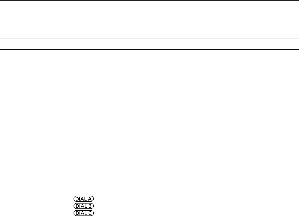
ABOUT THE INSTRUCTIONS
Instruction example
MENU
» SET > Time Set > Date
Detailed instruction
1. Push
MENU
.
Push
• The MENU screen opens.
2. Touch [SET].
MENU screen
• The SET screen opens.
3. Rotate to select “Time Set,” and then
push .
4.
Rotate to select “Date,” then push .
SET screen
This manual is described in the following manner.
“ ” (Quotation marks):
Used to indicate icons, setting items, and screen titles
displayed on the screen.
The screen titles are also indicated in uppercase
letters. (Example: FUNCTION screen)
[ ] (brackets):
Used to indicate keys.
Routes to the set modes and setting screens
Routes to the Set mode, setting screen and the setting
items are described in the following manner.
DATE/TIME screen
DATE screen
5. Touch [+] or [–] to set the date.
6. Touch [SET] to save the entry.
v
TABLE OF CONTENTS
PREFACE ................................................................... i
IMPORTANT ............................................................... i
TRADEMARKS ........................................................... i
EXPLICIT DEFINITIONS ............................................ i
FEATURES .................................................................ii
ABOUT THE SDR WIDEBAND RECEIVER CIRCUITS
...ii
VOICE CODING TECHNOLOGY ...............................ii
SUPPLIED ACCESSORIES .......................................ii
FCC INFORMATION .................................................iii
ABOUT THE INSTRUCTIONS ..................................iv
DAbout the touch operation ..............................iv
DTouch screen precautions ..............................iv
DTouch screen maintenance ............................iv
TABLE OF CONTENTS ............................................. v
PRECAUTIONS .......................................................viii
1 PANEL DESCRIPTION ....................................1-1
Front panel .......................................................1-1
Rear panel ........................................................1-3
Touch panel display .......................................... 1-4
DMULTI DIAL MENU ( ) ...................... 1-6
DMULTI DIAL MENU ( ) ...................... 1-6
DMULTI DIAL MENU ( ) ...................... 1-6
DMENU screen ..............................................1-6
DQUICK MENU .............................................1-6
DFUNCTION screen ......................................1-7
DFUNCTION items ........................................1-7
Keyboard entering and editing .........................1-7
DEntering and editing characters ..................1-7
DKeyboard types ...........................................1-8
DEntry example .............................................1-8
2 INSTALLATION AND CONNECTIONS ...........2-1
Selecting a location ..........................................2-1
Heat dissipation ................................................2-1
For desktop use ................................................2-1
Grounding .........................................................2-1
Connecting a DC power supply ........................2-1
DPower supply ...............................................2-1
DTurning the receiver's power ON or OFF ....2-1
Connecting an antenna .................................... 2-2
FSK (RTTY) connections .................................2-2
External device connection ..............................2-3
Adjusting the volume level ................................ 3-1
RF gain/SQL level/Audio tone ..........................3-1
DNoise squelch ..............................................3-1
DS-meter squelch ..........................................3-1
DRF gain ........................................................3-1
3 BASIC OPERATION ........................................3-1
Monitor function ................................................3-1
About the VFO and Memory modes .................3-1
Selecting the receiving mode ...........................3-1
Selecting the receiving mode (continued) ........3-2
Setting the frequency .......................................3-2
DDirectly entering a frequency ......................3-2
Changing the Tuning Step ................................3-2
DAbout the Tuning Step (TS) function ...........3-2
D
About the Programmable Tuning Step function
. 3-3
DAbout the Auto Tuning Step function ...........3-3
Selecting the antenna .......................................3-3
Dial/Panel Lock function ...................................3-3
DDial Lock function ........................................3-3
DPanel Lock function .....................................3-3
Adjusting Backlight dimmer ..............................3-4
Fine tuning ........................................................3-4
DWhen receiving FM, WFM or DIGITAL signal
.3-4
DWhen receiving FSK signal .........................3-4
Selecting meter display ...................................3-4
DMeter display types .....................................3-4
DRX Marker ...................................................4-1
Spectrum scope screen .................................... 4-1
4 SCOPE OPERATION .......................................4-1
DUsing the Spectrum Scope .........................4-1
DSetting the span ..........................................4-2
DSetting the range .........................................4-2
DSearching for the peak signal ...................... 4-3
DTouch screen operation ...............................4-3
DMini scope screen .......................................4-3
DAdjusting the Reference level .....................4-4
DSweep speed...............................................4-4
DScope set screen.........................................4-5
5 OTHER FUNCTIONS .......................................5-1
About the Function screen ...............................5-1
Preamplier ......................................................5-1
Attenuator .........................................................5-1
Selecting the antenna .......................................5-1
AGC function control ........................................5-1
IP Plus function ................................................5-2
Notch Filter .......................................................5-2
DSetting the notching width and frequency ...5-2
Using the Digital Twin PBT ............................... 5-2
Selecting the digital IF lter ..............................5-3
DAdjusting the passband width .....................5-3
DSelecting the lter shape .............................5-3
Noise Blanker (NB) ........................................... 5-4
Noise Reduction ...............................................5-4
Duplex operation ..............................................5-4
AFC function .....................................................5-5
Receiving in the CW mode ...............................5-5
DSetting the CW pitch control ........................ 5-5
DAbout the CW Reverse mode......................5-5
Receiving FSK (RTTY) signal ..........................5-5
DDecoded FSK data display .......................... 5-5
DDecoding FSK signal ................................... 5-5
DTurning ON the FSK log ..............................5-6
DViewing the FSK log contents .....................5-7
DTwin Peak Filter ...........................................5-7
DFSK tone and shift setting ...........................5-7
DAbout the FSK DECODE SET screen ......... 5-8
Tone squelch function .......................................5-9
D.SQL (Digital Squelch) function ......................5-9

vi
DDigital Code Squelch ................................... 5-9
DNetwork Access Code (NAC) ......................5-9
D Group Code (COM ID) and CC .................5-10
DRadio Access Number (RAN) ....................5-10
DUser Code (UC).........................................5-10
Descrambler function .....................................5-10
Decryption function ......................................... 5-10
Receive history log ......................................... 5-11
Screen Capture function ................................. 5-11
DCapturing a screen .................................... 5-11
DViewing the captured screen ..................... 5-11
6 RECORDING AND PLAYING BACK ...............6-1
Recording .........................................................6-1
DQuick recording ...........................................6-1
DNormal recording ......................................... 6-1
Playing back .....................................................6-1
Operation while playing back ...........................6-2
Playing back on a PC ....................................... 6-2
Checking the le information ............................6-3
Deleting a le ....................................................6-3
Deleting a folder ...............................................6-4
PLAYER SET screen ........................................6-4
RECORDER SET screen .................................6-4
7 USING AN SD CARD .......................................7-1
About the SD card ............................................ 7-1
DSD card’s folder contents ............................7-1
Saving data onto the SD card ..........................7-1
Inserting or removing the SD card .................... 7-1
DInserting.......................................................7-1
DRemoving (While the receiver is OFF) ........7-1
DRemoving (While the receiver is ON) ..........7-1
Formatting an SD card .....................................7-2
Saving in the old format .................................... 7-2
Saving the setting data .....................................7-2
Loading the data les .......................................7-3
Deleting a data le ............................................7-3
Checking SD card information .......................... 7-3
8 Memory channels ...........................................8-1
Selecting channel group ...................................8-1
DSelecting with / ......................8-1
DSelecting
on the [GROUP SELECT] screen ..8-1
Selecting a memory channel ............................8-2
DSelecting with .................................8-2
DSelecting with ..........................8-2
DSelecting using the keypad .........................8-2
Writing a memory channel ............................... 8-2
Copying the Memory contents .......................... 8-3
Inserting a blank channel .................................8-3
Clearing a memory channel .............................8-3
Entering a group/memory name .......................8-4
DEntering a group name ................................8-4
DEntering a memory name ............................8-4
About the MEMORY screen .............................8-5
9 SCANS .............................................................9-1
Scan types ........................................................9-1
Basic scanning .................................................9-1
DVFO scan and Memory scan ....................... 9-1
DPriority scan.................................................9-1
Adjusting the scan speed .................................9-1
Setting the Scan Resume function ................... 9-2
DSetting the scan delay timer ........................9-2
DSetting the Scan Resume function ..............9-2
Setting the priority interval ................................9-2
Priority scan ...................................................... 9-2
DPriority scan operation.................................9-2
DMonitoring the Priority channel .................... 9-2
Scan Setting screen .........................................9-3
Programmed scan and Fine Programmed scan
.....9-4
DProgrammed scan operation .......................9-4
DFine Programmed scan operation ...............9-4
∂F scan ............................................................9-5
D∂F scan operation ....................................... 9-5
DFine ∂F scan operation ............................... 9-5
Auto Memory Write scan ..................................9-6
DAuto Memory Write scan operation .............9-6
Memory scan and Select Memory scan ...........9-7
DMemory scan operation ............................... 9-7
DSelect Memory scan operation .................... 9-7
DSetting Select Memory channels ................. 9-8
D
Canceling the Select Memory channel settings
.. 9-8
Mode select memory scan ...............................9-9
DSetting the receive mode ............................9-9
Setting the skip frequency ............................... 9-9
DSetting the skip frequency ...........................9-9
DCanceling the skip frequency ......................9-9
Setting the Temporary Skip ............................9-10
Skip channel for memory scan .......................9-10
Voice Squelch Control function ...................... 9-11
Tone scan operation ....................................... 9-11
10 CLOCK AND TIMER ......................................10-1
Setting the Time and Date .............................. 10-1
DSetting date ...............................................10-1
DSetting time ...............................................10-1
NTP Time Server ............................................10-1
DExecute the time synchronization .............10-1
DSetting the NTP Server address ................10-1
Timer ..............................................................10-2
DSetting the Sleep timer ..............................10-2
DSetting the Daily timer ...............................10-2
Timer (continued) ...........................................10-3
DTimer setting items ....................................10-3
DAbout the Timer recording .........................10-3

vii
11 SET MODE ..................................................... 11-1
Set mode description ...................................... 11-1
DEntering the Set mode .............................. 11-1
Tone Control ................................................... 11-2
Function .......................................................... 11-2
Digital Set ....................................................... 11-4
Connectors ..................................................... 11-5
Network .......................................................... 11-7
Display ............................................................ 11-9
Time Set ....................................................... 11-10
SD Card ........................................................ 11-10
Others ........................................................... 11-10
12 MAINTENANCE .............................................12-1
Cleaning .........................................................12-1
Replacing fuse ................................................12-1
DDC power cable fuses ...............................12-1
DCircuitry fuse .............................................12-1
Resetting ........................................................12-2
DPartial reset ...............................................12-2
DAll reset .....................................................12-2
Touch screen calibration .................................12-3
Troubleshooting ..............................................12-4
13 UPDATING THE FIRMWARE ........................13-1
General ...........................................................13-1
DAbout updating the rmware .....................13-1
DChecking the rmware version ..................13-1
Preparation .....................................................13-1
DDownloading the rmware le ...................13-1
DUnzipping the rmware folder....................13-1
Updating the rmware ....................................13-2
14 SPECIFICATIONS .........................................14-1
DGeneral......................................................14-1
DReceiver ....................................................14-1
15 OPTIONS .......................................................15-1
Options ...........................................................15-1
Attaching the MB-123 .....................................15-1
16 CONNECTOR INFORMATION ......................16-1
ABOUT THE LICENSES ............................................ I
INDEX........................................................................ II

viii
PRECAUTIONS
R DANGER! NEVER operate the receiver near unshielded
electrical blasting caps or in an explosive atmosphere. This
could cause an explosion and death.
R WARNING! NEVER operate the receiver with a headset
or other audio accessories at high volume levels. If you
experience a ringing in your ears, reduce the volume or
discontinue use.
R WARNING! NEVER apply AC power to the [DC13.8V]
socket on the receiver rear panel. This could cause a re or
damage the receiver.
R WARNING! NEVER apply more than 16 V DC to the
[DC13.8V] socket on the receiver rear panel. This could
cause a re or damage the receiver.
R WARNING! NEVER reverse the DC power cable
polarity. This could cause a re or damage the receiver.
R WARNING! NEVER remove the fuse holder on the DC
power cable. Excessive current caused by a short could
cause a re or damage the receiver.
R WARNING! NEVER let metal, wire or other objects
contact the inside of the receiver, or make incorrect contact
with connectors on the rear panel. This could cause an
electric shock or damage the receiver.
R WARNING! NEVER operate or touch the receiver with
wet hands. This could cause an electric shock or damage
to the receiver.
R WARNING! Immediately turn OFF the receiver power
and remove the power cable from the receiver if it emits an
abnormal odor, sound or smoke. Contact your Icom dealer
or distributor for advice.
R WARNING! NEVER put the receiver on an unstable
place where the receiver may suddenly move or fall. This
could cause an injury or damage the receiver.
R WARNING! NEVER operate the receiver during a
lightning storm. It may result in an electric shock, cause a
re or damage the receiver. Always disconnect the power
source and antenna before a storm.
CAUTION: NEVER expose the receiver to rain, snow or
any liquids.
CAUTION: NEVER change the internal settings of the
receiver. This could reduce receiver performance and/
or damage to the receiver. The receiver warranty does
not cover any problems caused by unauthorized internal
adjustments.
CAUTION: NEVER install or place the receiver in a place
without adequate ventilation.
CAUTION: NEVER use harsh solvents such as Benzine
or alcohol when cleaning, as they will damage the receiver
surfaces.
CAUTION: NEVER leave the receiver in areas with
temperatures below –10°C (+14°F) or above +60°C
(+140°F).
CAUTION: NEVER place the receiver in excessively dusty
environments. This could damage the receiver.
DO NOT place the receiver against walls or put anything on
top of the receiver. This may overheat the receiver.
BE CAREFUL! The receiver will become hot when
operating the receiver continuously for long periods of time.
NEVER leave the receiver in an insecure place to avoid use
by unauthorized persons.
Turn OFF the receiver’s power and/or disconnect the DC
power cable when you will not use the receiver for long
period of time.
The display may have cosmetic imperfections that appear
as small dark or light spots. This is not a malfunction or
defect, but a normal characteristic of LCDs.
The IC-R8600 may receive its own oscillated frequency,
resulting in no reception or only noise reception including
on the Spectrum Scope screen, on some frequencies.
1PANEL DESCRIPTION
1-11-1
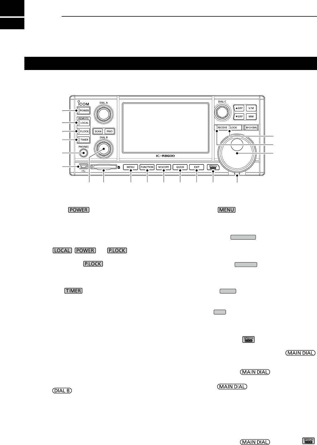
Front panel
q POWER KEY (p. 2-1)
Turns the receiver ON (lights blue) or OFF.
w LOCAL KEY (p. 16-2)
Turns OFF the Remote mode.
L In the Remote mode, all the operations on the panel
except , and are locked.
e PANEL LOCK KEY (p. 3-3)
Locks the controls (lights white) on the front panel.
L Hold down for 1 second to turn OFF the display.
r TIMER KEY (p. 10-2)
Turns ON (lights orange) or OFF the Timer function.
L Set the current time to use the Timer function. (p. 10-1)
t HEADPHONE JACK [PHONES] (p. 16-2)
Accepts headphones. (3.5 mm: 1/8 in (d))
y [USB] (mini-B type) PORT (pp. 2-3, 16-1)
Connects to a PC.
• Outputs the decoded FSK (RTTY) or D-STAR data.
• Outputs the demodulated AF signal or 12 kHz IF signal.
• Interface for the optional CS-R8600 or RS-R8600
(future product).
• Interface for the remote control by the CI-V command.
u DIAL B (p. 1-6)
• Rotate to adjust the audio output level.
• Push to display the setting menu, then rotate to adjust
the RF gain (sensitivity), squelch threshold levels or
audio tone (Treble or Bass).
• Hold down to turn ON the Monitor function (the squelch
opens).
i SD CARD SLOT [SD CARD] (pp. 7-1, 7-2)
Accepts an SD card.
o MENU KEY (pp. 1-6, 11-1)
Opens the MENU screens where you can modify
the receiver settings and edit memory channels.
!0 FUNCTION KEY
FUNCTION
(pp. 1-7, 5-1)
Displays the FUNCTION screen where you can
congure various settings.
!1 MINI SCOPE KEY
M.SCOPE
(p. 4-3)
• Push to display the Mini Scope.
• Hold down for 1 second to display the Spectrum Scope.
!2 QUICK KEY
QUICK
(p. 1-6)
Displays the QUICK MENU.
!3 EXIT KEY
EXIT
Exits a setting screen or returns to the previous
screen.
!4 SPEECH/LOCK KEY (p. 3-3)
• Push to announce the receiving frequency and mode.
•
Hold down for 1 second to lock (lights white) .
!5 TENSION ADJUSTER
Adjusts the friction of in 3 steps.
!6 MAIN DIAL
Changes the operating frequency or setting value.
!7 RECEIVE INDICATOR
Lights green while receiving a signal or the squelch
(p. 3-1) is opened.
!8 LOCK INDICATOR (p. 3-3)
Lights white while the is locked by .
This section describes the keys, controls and dials that you use to operate the IC-R8600.
Refer to the pages posted beside each key, control, or dial for details.
q
w
e
r
t
y
u i o !0 !1 !2 !3 !4 !5
!6
!7
!8
1
PANEL DESCRIPTION
1
2
3
4
5
6
7
8
9
10
11
12
13
14
15
16
17
18
19
20
21
1-2
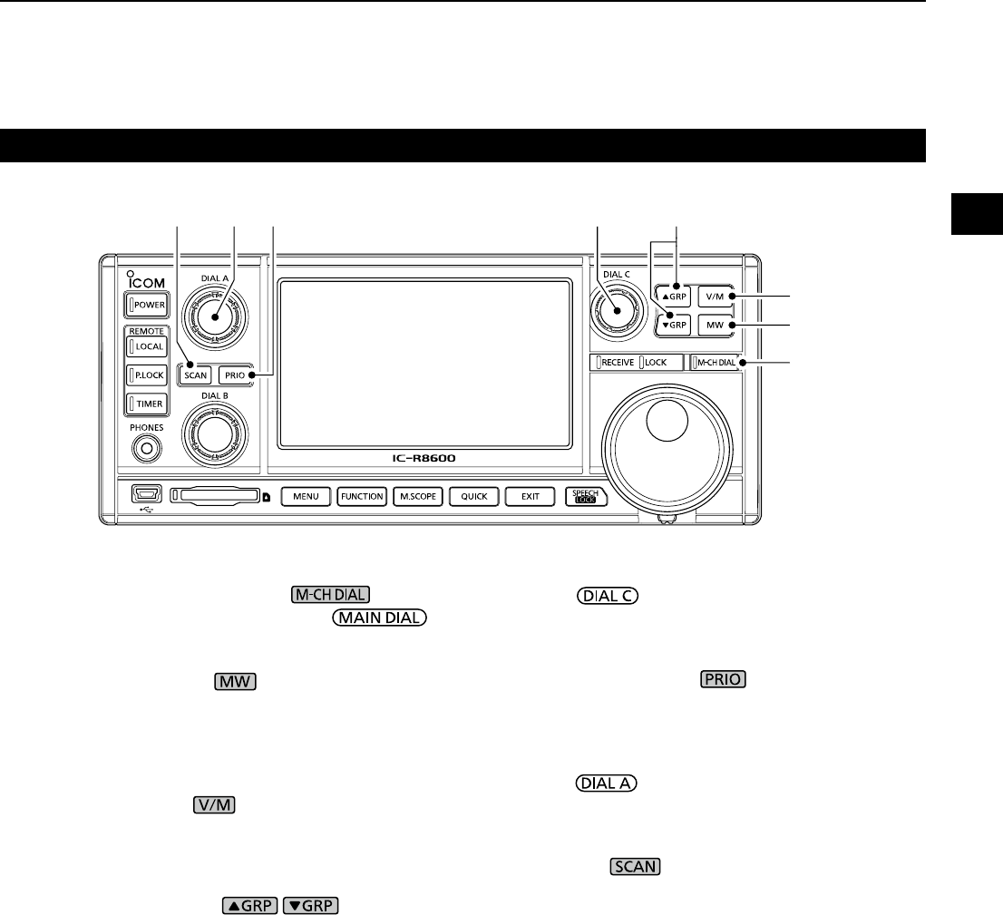
Front panel (Continued)
!9!9
@0
@1
@2@3
@5 @4
@6
!9 MEMORY CHANNEL DIAL KEY (p. 8-2)
Push this key (lights white) then rotate
to change the Memory channel number.
@0 MEMORY WRITE KEY (p. 8-2)
• Push to open the MW MENU screen.
• Hold down for 1 second to write the current receiving
contents (frequency, mode, and so on) to a memory
channel.
@1 VFO/MEMORY KEY (p. 3-1)
• Push to toggle between the VFO and Memory modes,
• Hold down for 1 second to copy the selected memory
channel contents to the VFO.
@2 MEMORY GROUP KEY / (p. 8-1)
Changes the Memory channel group.
@3 DIAL C (p. 1-6)
• Push to display the Multi Dial menu.
• Turn to change the memory channel number.
@4 PRIORITY SCAN KEY (p. 9-2)
Starts or cancels a Priority scan.
L Select a Memory channel before starting a Priority
scan.
@5 DIAL A (p. 1-6)
• Push to display the scan setting menu, then rotate to
set the Scan speed or Priority scan interval.
@6 SCAN KEY (p. 9-1)
• Push to display the SCAN START screen.
• Hold down for 1 second to start a scan (except Priority
scan).
1PANEL DESCRIPTION
1-3
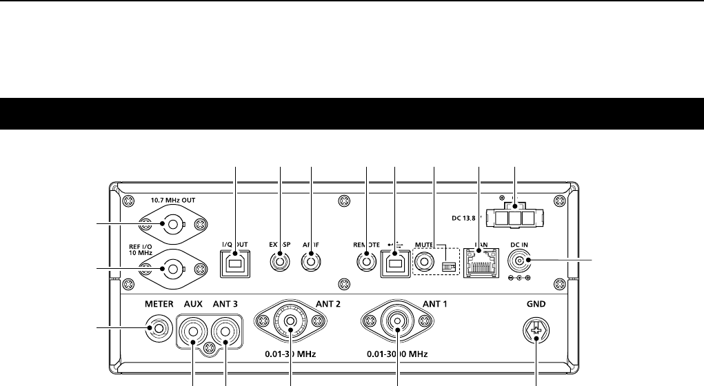
Rear panel
q DC POWER SOCKET [DC 13.8 V] (pp. 2-1, 16-2)
Connects to the supplied DC power cable.
w DC INPUT JACK [DC IN] (pp. 2-1, 16-2)
Connects to the optional SP-39AD (External speaker with
built-in power adapter) or AD-55NS (Power adapter).
L
Before connecting an SP-39AD or AD-55NS, connect the
supplied DC power short connector to [DC 13.8V] (q).
e GROUND TERMINAL [GND] (p. 2-1)
Connects to ground to prevent electrical shocks
and other problems.
r ANTENNA CONNECTOR [ANT1] (N type) (p. 2-2)
Connects to a 10 kHz ~ 3000 MHz antenna.
t ANTENNA CONNECTOR [ANT2] (SO-239) (p. 2-2)
Connects to a 10 kHz ~ 30 MHz antenna.
y ANTENNA CONNECTOR [ANT3] (RCA) (p. 2-2)
Connects to a 10 kHz ~ 30 MHz antenna.
u AUX JACK [AUX]
A reserved jack. No internal connection.
i EXTERNAL METER JACK [METER]
(pp. 2-3, 16-1)
Connects to an external analog RSSI or squelch
level meter (user supplied).
o REFERENCE SIGNAL INPUT/OUTPUT
CONNECTOR [REF I/O 10MHz] (BNC) (p. 16-1)
Inputs or outputs a 10 MHz reference frequency signal.
!0 IF SIGNAL OUTPUT CONNECTOR
[10.7MHz OUT] (BNC) (p. 16-1)
Outputs a 10.7 MHz IF signal.
!1 I/Q DATA OUTPUT PORT [I/Q OUT] (pp. 2-3, 16-1)
Outputs I/Q data.
LConnect a USB (1.1/2.0 standard) port (B type).
!2
EXTERNAL SPEAKER JACK [EXT-SP] (pp. 2-3, 16-2)
Connects to an optional external speaker SP-39AD
(External speaker with built-in power adapter).
(3.5 mm: 1/8 in (d))
LAccepts a 4~8 Ω speaker.
!3 AF/IF OUTPUT JACK [AF/IF] (pp. 2-3, 16-1)
Outputs the demodulated AF signal, or a 12 kHz IF
signal.
LThe output level is set, regardless of the volume control.
!4
REMOTE CONTROL JACK [REMOTE] (pp. 2-3, 16-2)
Connects to a PC for remote control using CI-V
commands. (3.5 mm: 1/8 in (d))
!5 [USB] (B type) PORT (p. 2-3, 16-1)
Connects to a PC.
• Outputs the decoded FSK (RTTY) or D-STAR data.
• Outputs the demodulated AF signal or 12 kHz IF signal.
• Interface for the optional CS-R8600 or RS-R8600
(future product).
• Interface for the remote control by the CI-V commands.
!6 [MUTE] JACK/[MUTE] SWITCH (pp. 2-3, 16-1)
Used for the Mute function, or Bit Error Rate (BER)
Measurement function. (3.5 mm: 1/8 in (d))
L Slide the switch to the left when you use the
Mute function. The IC-R8600's receive circuitry is
deactivated by the input voltage.
L Slide the switch to the right when you use the BER
Measurement function.
!7 LAN PORT [LAN] (pp. 2-3, 16-1)
Connects to a network to use the functions shown
below.
• Automatic time synchronization.
• Outputs the received signal in
demodulated AF signal
, or
in 12 kHz IF signal, through the network.
• Remotely controlling using the optional RS-R8600
(future product).
o
!0
w
i
t r e
yu
!7
!1 !3!2 !4 !5 q
!6
1
PANEL DESCRIPTION
1
2
3
4
5
6
7
8
9
10
11
12
13
14
15
16
17
18
19
20
21
1-4
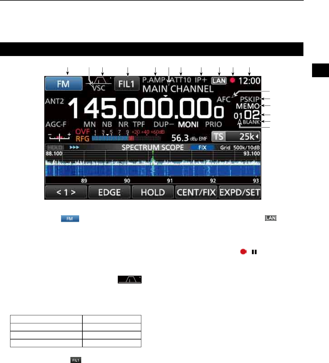
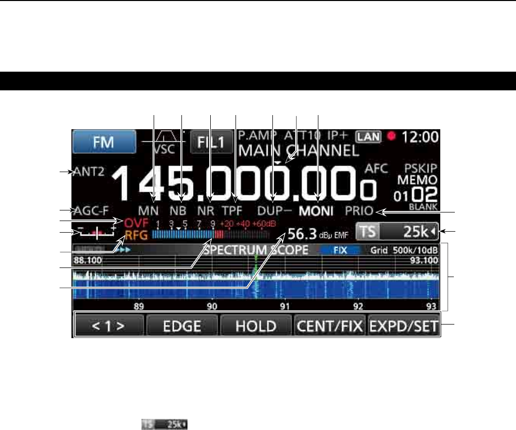
Touch panel display
q MODE INDICATOR (p. 3-1)
Displays the selected receive mode.
w VSC INDICATOR (pp. 9-11, 5-10)
Appears while the Voice Squelch Control (VSC)
function is ON.
SCRM:
Appears while the Scrambler function is ON.
ENCR:
Appears while the Encryption function is ON.
e
PASSBAND WIDTH INDICATOR (BW/SFT)
(pp. 5-2, 5-9)
• Graphically displays the digital IF lter passband width
and the shift amount.
• While the Tone/Digital Squelch function is ON, displays
the tone/digital squelch type.
TSQL: Tone squelch COM ID: Common ID
DTCS: Digital tone squelch CC: –
CSQL: Digital code squelch RAN:
Radio access number
NAC: Network access code UC: User code
r IF FILTER INDICATOR (p. 5-3)
Displays the selected IF lter (FIL1, FIL2 or FIL3).
t PREAMP INDICATOR (pp. 1-7, 5-1)
Is displayed while the preampli er is ON.
y MEMORY NAME READOUT (p. 8-5)
Displays the memory name if entered.
u ATTENUATOR INDICATOR
(ATT10/ATT20/ATT30) (pp. 1-7, 5-1)
Is displayed while the attenuator is ON.
i IP+ ICON (pp. 1-7, 5-2)
Is displayed while the IP Plus function is ON.
(This screen is only an example.)
o NETWORK CONTROL INDICATOR
Is displayed
while the IC-R8600 is remotely
controlled by the optional RS-R8600 (future
product), through the network.
!0 VOICE RECORDER ICON / (p. 6-1)
Is displayed while recording to indicate the
recording status.
!1 CLOCK READOUT (p. 10-1)
Displays the current local time.
L Touch the readout to display both the current local time
and UTC time.
!2 AFC INDICATOR (p. 5-5)
Is displayed while the Automatic Frequency Control
(AFC) function is ON.
!3 SKIP INDICATOR (pp. 9-9, 9-10)
SKIP: Memory Skip
P
SKIP: Program Skip
!4 OPERATING MODE INDICATOR (p. 3-1)
VFO
: VFO mode
MEMO
: Memory mode
!5 MEMORY CHANNEL READOUT (pp. 3-1, 8-2)
Displays the selected memory channel number.
!6 BLANK MEMORY CHANNEL INDICATOR (p. 8-3)
Is displayed when the selected memory channel is blank.
!7 MEMORY CHANNEL GROUP INDICATOR (p. 8-1)
00~99: Memory channel group number
A: Auto memory write group
S: Scan skip group
P: Programmable scan edge group
q e rtuio!0 !1
y
!3
!4
!5
!6
w
!7
!2
1PANEL DESCRIPTION
1-5
Touch panel (Continued)
(This screen is only an example.)
!8 PRIORITY INDICATOR (p. 9-2)
Is displayed
during a Priority scan.
L Blinks while the squelch is forced to open during a
Priority scan. (p. 9-3)
!9 TUNING STEP INDICATOR (p. 3-2)
Displays the currently selected tuning step.
L If the tuning step is set by the programmable tuning
step, "◄" is displayed by the indicator.
@0 FUNCTION SCREEN
Displays the operating parameters, modes,
frequencies and indicators, depending on your
selections.
@11 FUNCTION GUIDES
Displays the currently accessible function.
@2
RECEIVED SIGNAL STRENGTH INDICATOR (p. 3-4)
Displays the absolute received signal strength in
terminated or open load measurement.
@3 SIGNAL METER (p. 3-5)
Indicates the signal strength in S-meter/dBµ/
dBµ(EMF)/dBm.
@4 RF GAIN (RFG) (p. 3-1)
Is displayed
when the RF gain is set to less than
100% to indicate that the RF gain is reduced.
@5 TUNING INDICATOR (p. 3-4)
Displays the detuned level in the FM, WFM, FSK
and DIGITAL modes.
@6 OVERFLOW (OVF) INDICATOR (pp. 3-1, 5-1)
Is displayed when an excessively strong signal
is received. (Normally, "S" is displayed to in the
S-Meter mode)
@7 AGC INDICATOR (pp. 1-7, 5-1)
Displays the selected AGC time constant setting.
(AGC-F: Fast, AGC-M: Mid, AGC-S: Slow or AGC-OFF: OFF).
@8
ANTENNA INDICATOR (p. 3-3, 5-1)
Displays the selected antenna (ANT1, ANT2 or ANT3) only
when the frequency is set to 10 kHz ~ 29.999999 MHz.
@9 NOTCH INDICATOR (AN/MN) (pp. 1-7, 5-2)
Is displayed while the Notch function is ON. (AN:
Auto Notch or MN: Manual Notch)
#0 NOISE BLANKER INDICATOR (NB) (pp. 1-7, 5-4)
Is displayed while the Noise Blanker function is ON.
#1 NOISE REDUCTION INDICATOR (NR) (p. 1-7, 5-4)
Is displayed while the Noise Reduction function is ON.
#2 TWIN PEAK FILTER INDICATOR (TPF) (p. 5-7)
Is displayed while the Twin Peak Filter function is ON.
#3 DUP INDICATOR (DUP–/DUP+) (pp. 1-7, 5-4)
Is displayed while in the Duplex mode.
#4 TS INDICATOR ("▼") (p. 3-2)
Is displayed when the TS function is on. The
frequency changes according to the tuning step set
in TUNING STEP INDICATOR (
!9
).
L Touch kHz digit to turn OFF the TS function.
#5 MONITOR INDICATOR (MONI) (p. 3-1)
Appears while the Monitor function is ON.
@9 #0 #1 #2 #3 #5
@8
@7
@5
!8
!9
@6
@0
@1
@4
@2
@3
#4
1
PANEL DESCRIPTION
1
2
3
4
5
6
7
8
9
10
11
12
13
14
15
16
17
18
19
20
21
1-6
Touch panel (Continued)
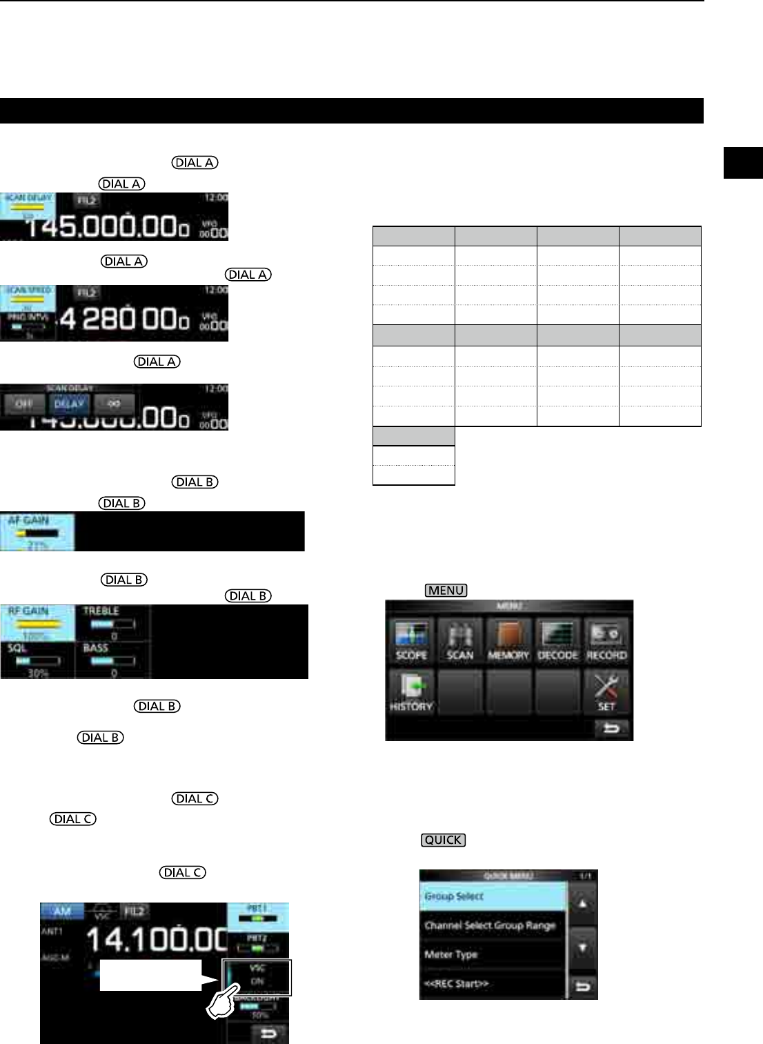
z Push to open the Multi Dial menu.
Push again to close the menu.
z While the Multi Dial menu is opened, touch the
desired item and rotate to set the desired
value or function.
DMENU screen
z Push to open the MENU screen.
L The menu items differ, depending on the selected receive
mode.
DMULTI DIAL MENU ( )
DMULTI DIAL MENU ( )
DMULTI DIAL MENU ( )
• When rotating .
• When rotating .
• When pushing .
LTouch to select an item, then rotate .
• When pushing .
LTouch to select an item, then rotate .
• When holding down for 1 second.
LTouch an item.
• When holding down for 1 second.
• The Monitor function is turned ON ([RECEIVE] lights green).
LRelease to turn OFF the Monitor function.
DQUICK MENU
z Push to open the QUICK MENU.
L The items differ, depending on the operating condition.
QUICK MENU example
Touch the key to
turn ON and OFF
Multi dial menu items
Displayed items differ, according to the selected
receive mode.
FM/WFM AM/S-AM SSB CW
AFC*1 PBT1 PBT1 PBT1
PBT2 PBT2 PBT2
VSC*1 VSC*1 VSC*1 CW PITCH
BACKLIGHT BACKLIGHT BACKLIGHT BACKLIGHT
FSK DIGITAL NB*2NR*2
PBT1 AFC*1 LEVEL LEVEL
PBT2 DEPTH
TPF*1 WIDTH
BACKLIGHT BACKLIGHT
NOTCH*2
POSITION
WIDTH*1
*1 Touch to turn the function ON or OFF.
*2 Displayed when you touch the item on the FUNCTION
screen for 1 second.
1PANEL DESCRIPTION
1-7
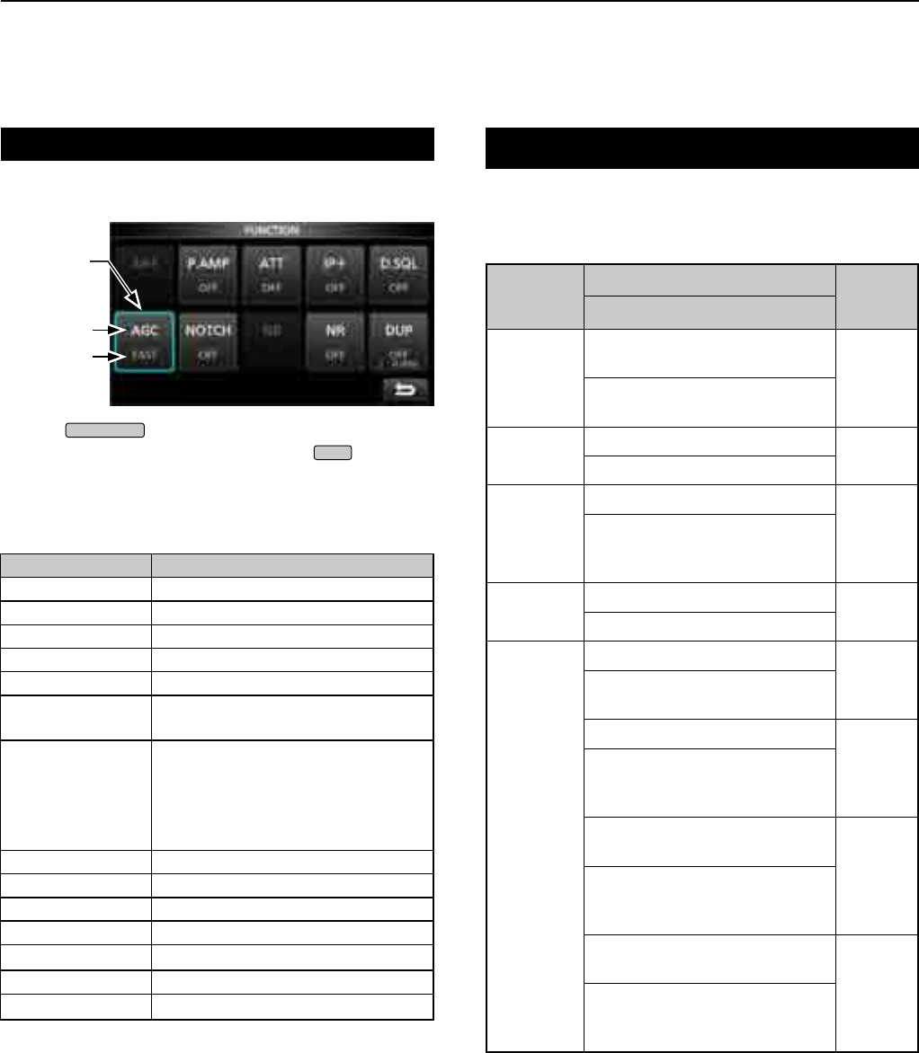
Touch panel (Continued)
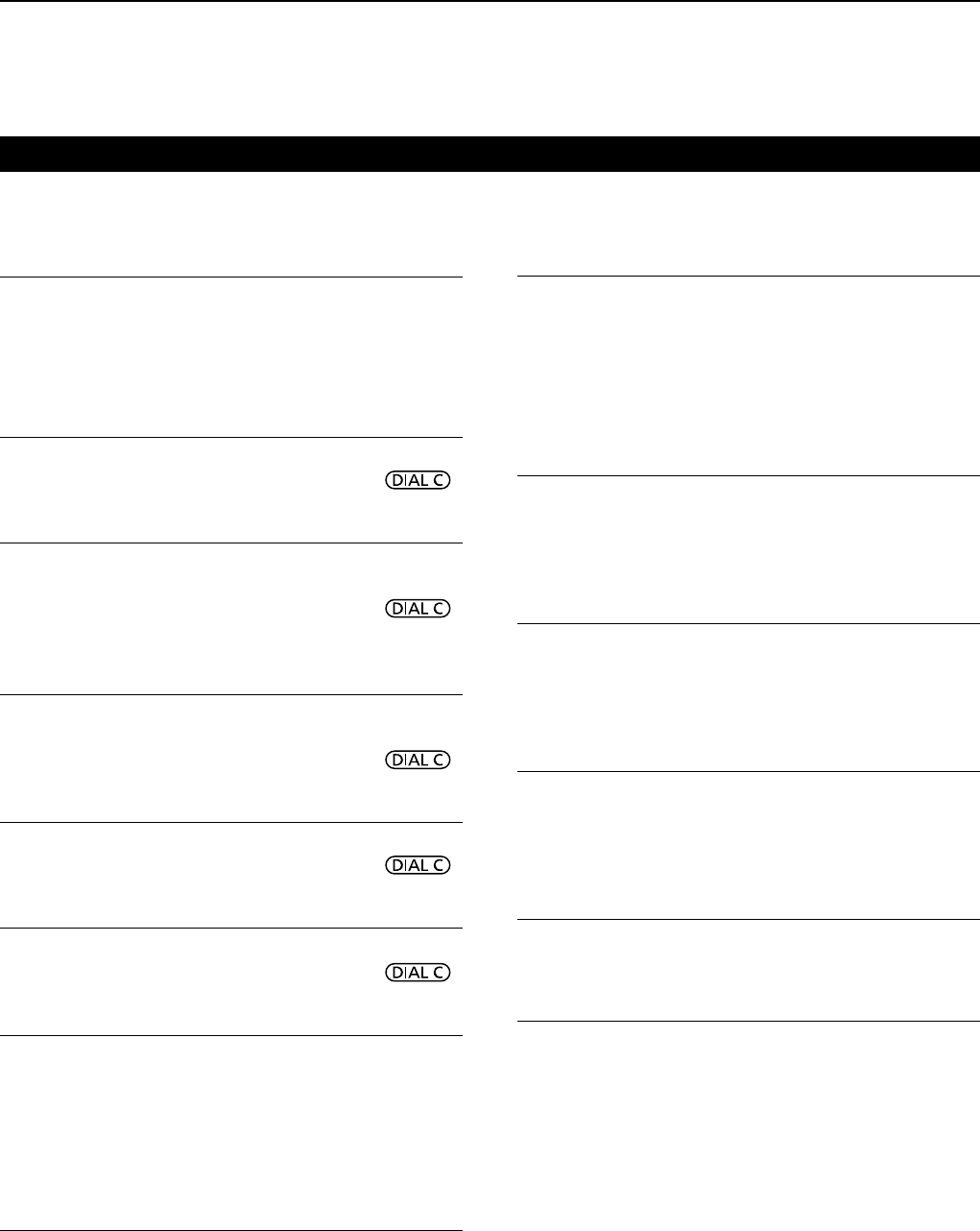
DFUNCTION screen
z Push
FUNCTION
to open the FUNCTION screen.
LTo close the FUNCTION screen, push
EXIT
.
Function
name
Selected
option
Lights blue
in use
DFUNCTION items
zTouch an item to change its setting.
*1 Touch for 1 second to open its function menu.
*2 Touch to open its function menu.
FUNCTION OPTION
ANT ANT1, ANT2 or ANT3
P.AMP OFF or ON
ATT OFF, 10dB, 20dB or 30dB
IP+ OFF or ON
TONE*1OFF, TSQL or DTCS
TONE/SHIFT*2FSK RX Frequency, FSK Tone
Frequency or FSK Shift width
D.SQL*1
D-STAR: OFF or CSQL
P25: OFF or NAC
dPMR: OFF, COM ID or CC
NXDN: OFF or RAN
DCR: OFF or UC
AGC*1FAST, MID or SLOW
NOTCH*1OFF, AN or MN
NB*1OFF or ON
SCRAM*1OFF or ON
ENCRYP*1OFF or ON
NR*1OFF or ON
DUP*1OFF, DUP– or DUP+
Category Edit items
Total
character
number
Selectable characters
MEMORY
GROUP NAME
MEMORY NAME 16
A to Z, a to z, 0 to 9, (space), @
% & # + - = [ ] / ( ) : ; ˄ ! ? < > . ,
DISPLAY OPENING COMMENT 10
A to Z, 0~9, (space), / @ - .
SD card
FILE NAME*
15
A to Z, a to z, 0 to 9, (space),
@ % & # + - = [ ] / ( ) : ; ^ ! ? < >
, . " $ ' * \ _ ` { } | ~
TIME NTP SERVER ADDRESS 64
A to Z, a to z, 0~9, (space), - .
NETWORK
NETWORK NAME
15
A to Z, 0 to 9, (space), ! " # $ %
& ( ) + , - . ; = @ [ ] ^ _ ' { } ~
NETWORK RADIO NAME
16
A to Z, a to z, 0 to 9, (space), ! "
# $ % & ' ( ) * + , - . / : ; < > = ?
@ [ ] ^ _ ` { } | ~
NETWORK USER1 ID
NETWORK USER2 ID
16
A to Z, a to z, 0 to 9, (space), ! "
# $ % & ' ( ) * + , - . / : ; < > = ?
@ [ ] ^ _ ` { } | ~
NETWORK USER1 PASSWORD
NETWORK USER2 PASSWORD
16
A to Z, a to z, 0 to 9, (space), ! "
# $ % & ' ( ) * + , - . / : ; < > = ?
@ [ ] ^ _ ` { } | ~
*Illegal characters " / : ; * < > "
Keyboard entering and editing
DEntering and editing characters
You can enter and edit characters in the items in the
following table.
1
PANEL DESCRIPTION
1
2
3
4
5
6
7
8
9
10
11
12
13
14
15
16
17
18
19
20
21
1-8
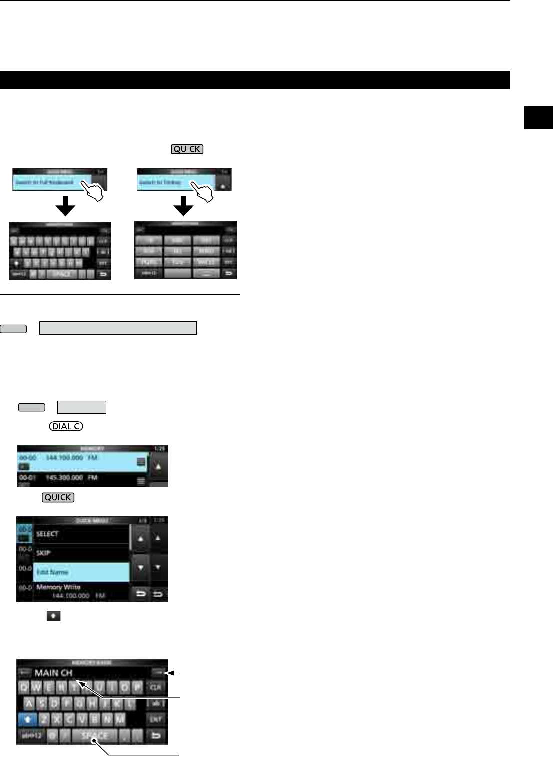
DEntry example
Example: Entering memory name "MAIN CHANNEL."
1. Open the MEMORY screen.
MENU
» MEMORY
2. Rotate to select the channel you want to
enter a name in.
3.
Push .
4. Touch “Edit Name.”
5. Touch for 1 second to select the upper case
entry mode.
6. Enter a name of up to 16 characters, then touch [ENT].
• The entered name is displayed.
DKeyboard types
You can select the Full Keyboard or Tenkey in
“Keyboard Type” in the QUICK MENU.
1. When the keypad is opened, push .
2. Touch to select the keyboard type.
MENU
» SET > Function > Keyboard Type
InformationL
You can also select the Keyboard type in the Set mode.
Keyboard entering and editing (Continued)
Enters a space
Cursor
Moves the cursor
forward
Switched to Full Keyboard Switched to Tenkey
2INSTALLATION AND CONNECTIONS
2-12-1
Selecting a location
For desktop use
Select a location for the receiver that allows adequate
air circulation, free from extreme heat, cold or
vibrations, and other electromagnetic sources.
An improper location may damage the receiver.
Never place the receiver in areas such as:
• Temperatures below –10°C (+40°F) or above +60°C
(+140°F).
• Unstable place slope or vibrate.
• In direct sunlight.
• High humidity and temperature.
• Dusty environments.
• Noisy environments.
DPower supply
You can use any of the power sources listed below.
• 13.8 V DC power supply (User supplied)
• Optional SP-39AD
(External speaker with built-in power supply)
• Optional AD-55NS (Power adapter)
DTurning the receiver's power ON or OFF
zPush to turn ON the power.
z Hold down until the "POWER OFF..." is
displayed.
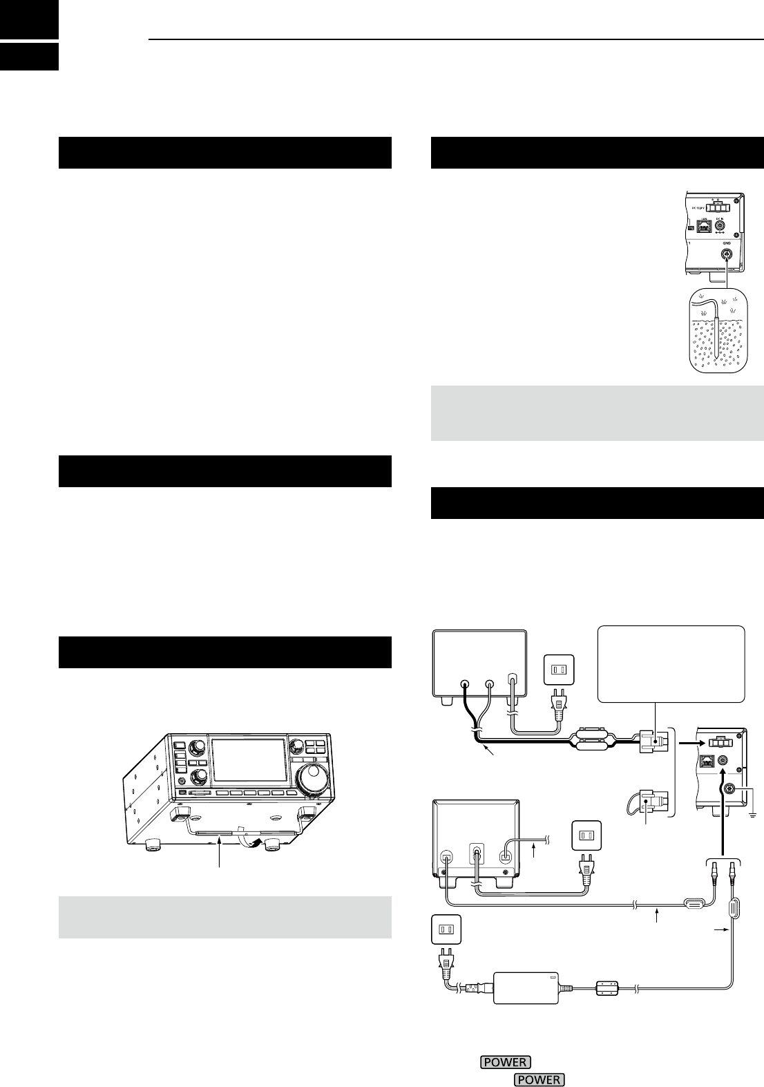
The receiver has a stand for desktop use.
zPull the stand until it locks in place.
CAUTION: NEVER carry the receiver by holding the stand,
dials, controls and so on. This may damage them.
Heat dissipation
Grounding
To prevent electrical shock, interfere
from other electric devices and other
problems, ground the receiver using
the ground terminal [GND] on the rear
panel.
For best results, connect a heavy
gauge wire or strap to a long ground
rod. Make the distance between the
[GND] terminal and ground as short as
possible.
RWARNING! NEVER connect the [GND] terminal
to a gas or electric pipe, since the connection could
cause an explosion or electric shock.
• DO NOT place the receiver against walls, or put
anything on top of the receiver. This may block airow.
• NEVER install the receiver in a place without
adequate ventilation. Heat dissipation may be
reduced, and the receiver may be damaged.
Stand
Connecting a DC power supply
+
_
IC-R8600
AC outlet
When disconnecting,
rmly push down the
locking tab and then pull
the connector out of the
socket.
AC outletShort connector:
Connect when
SP-39AD or
AD-55NS is used.
AC outlet DC power cable
AD-55NS (Option)
SP-39AD
(Option)
Speaker
cable
Supplied DC power cable
Red
External power supply
(User supplied)
Black
2
INSTALLATION AND CONNECTIONS
1
2
3
4
5
6
7
8
9
10
11
12
13
14
15
16
17
18
19
20
21
2-2
InformationL .
Antenna is a very important element in receiving
signal. Use the antenna and coaxial cable of
appropriate impedance.
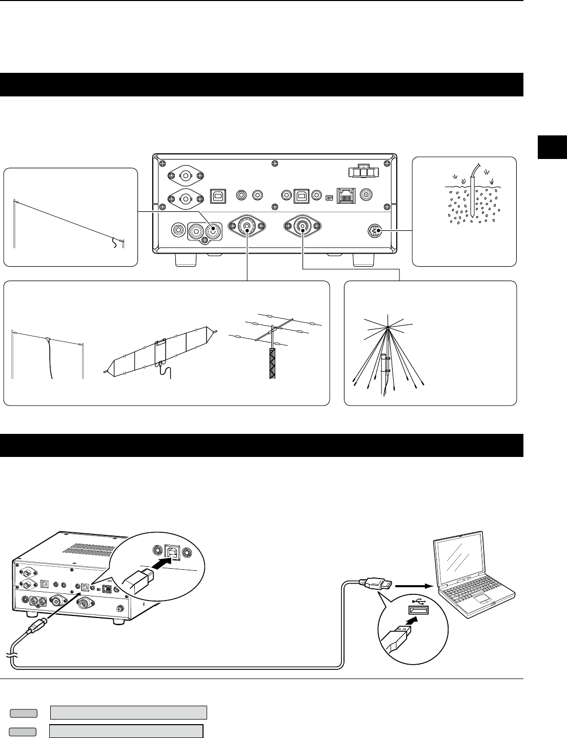
Connecting an antenna
FSK (RTTY) connections
The receiver has a built-in FSK (RTTY) decoder.
Connect the IC-R8600 and a PC that has an FSK (RTTY) software (user supplied) installed through the USB port,
to decode the FSK signal. Refer to the software application’s instruction manual for setup details.
L Icom does not guarantee performance of the application software, PC, network device or network settings.
• You can change the FSK output port on the MENU screen.
• You can download the USB driver and installation guide from the Icom website.
http://www.icom.co.jp/world/support/download/rm/index.html
MENU
» SET > Connectors > USB (Front)
MENU
» SET > Connectors > USB (Rear)
To the USB port Type A
IC-R8600
Type B
A user supplied A/B USB cable
PC with RTTY
software installed
To a USB port
When you use a long wire antenna for short wave
bands, use one as long as possible (at least 10 m,
32.8 ft).
0.01 MHz ~ 30 MHz (500 Ω)
0.01 MHz ~ 30 MHz (50 Ω) 0.01 MHz ~ 3000 MHz (50 Ω)
Wire dipole antenna Yagi antenna
Discone antenna
Grounding prevents
electrical shock
and another problems.
Folded-dipole antenna (T2FD type)
Long wire antenna
ANT 3 jack (RCA type)
ANT 2 connector (SO-239) ANT 1 connector (N type)
GND terminal
2INSTALLATION AND CONNECTIONS
2-3
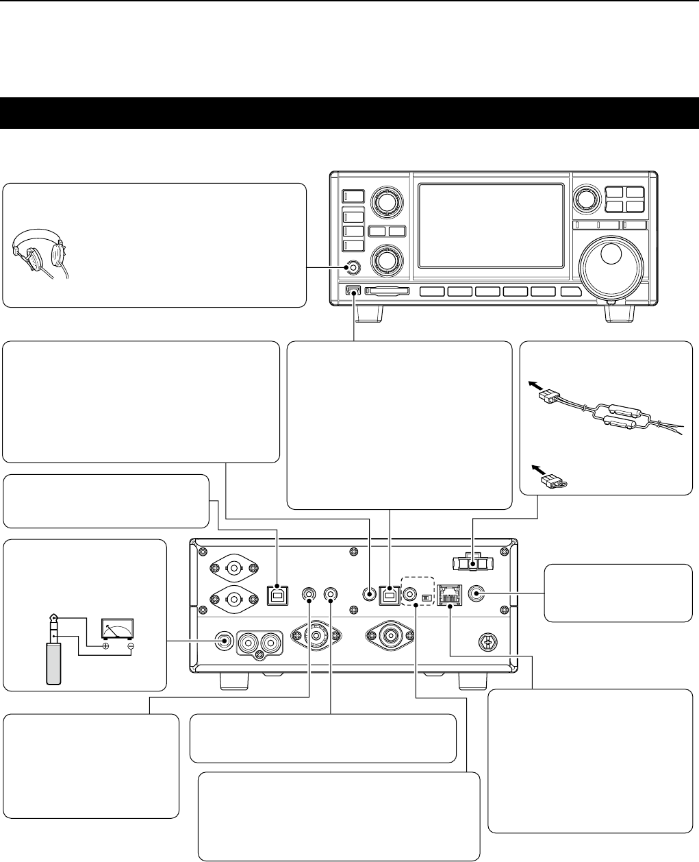
External device connection
[DC 13.8 V] DC power connector
(p. 16-2)
[DC IN] jack (p. 16-2)
[LAN] port (p. 16-1)
[AF/IF] jack
(3.5 mm: 1/8 in (d))
(p. 16-1)
[METER] jack (p. 16-1)
[I/Q OUT] port
(USB B type)
(p. 16-1)
[MUTE] jack
(3.5 mm: 1/8 in (d))
(p. 16-1)
MUTE switch (p. 16-1)
CAB-1258
(Supplied)
OPC-1605 (Supplied)
Connect when an SP-39AD
or AD-55NS is used.
Connects the optional SP-
39AD or AD-55NS.
Connects to a network to use
the functions shown below.
• Automatic time synchronization.
• Outputs the demodulated audio
signal or 12 kHz IF signal to the
network.
• Remote control using the optional
RS-R8600 (future product).
Outputs the demodulated audio signal or 12 kHz IF
signal to the network.
Outputs the voltage that
represents the received signal
strength or squelch levels to an
external meter.
Outputs the In phase/
Quadrature (I/Q) data.
Inputs the Mute control signal.
Used for the Bit Error Rate (BER) measurement
function.
[REMOTE] jack (p. 16-2)
(3.5 mm: 1/8 in (d))
[EXT-SP]
(External speaker) jack
(p.
16-2
) (3.5 mm: 1/8 in (d))
Connects the optional
SP-39AD or SP-23.
[USB] port (p. 16-1)
L Mini-B type on the front panel, B type
on the rear panel.
• Outputs the decoded FSK (RTTY) or
D-STAR data to the PC.
• Outputs the demodulated audio or
12 kHz IF signal to the PC.
• Remote control operation using the
optional RS-R8600 (future product).
• Programing using the optional CS-
R8600.
Accepts headphones with 8 ~ 16 Ω
impedance.
• Outputs more than 50 mW into an 8 Ω load.
• The volume level may differ, depending
on the headphones.
[PHONES] Headphones (p. 16-2)
L Icom does not guarantee the performance of the PC, network device or network settings.
Remotely controls the receiver, using the CI-V
commands.
L Refer to the Icom web site for the CI-V
commands.
http://www.icom.co.jp/world/support/download/Manual
(3.5 mm: 1/8 in (d))
3
BASIC OPERATION
1
2
3
4
5
6
7
8
9
10
11
12
13
14
15
16
17
18
19
20
21
3-13-1
L The status or position of each key or dial is stored and
recalled when the power is turned ON.
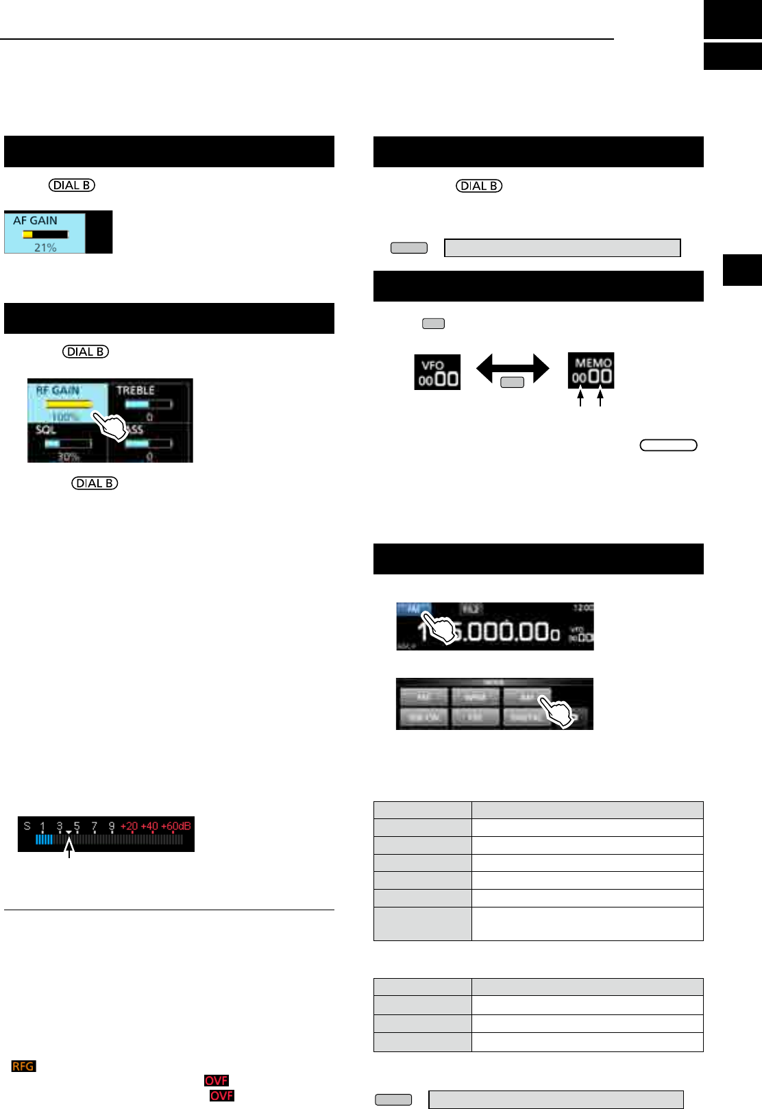
Rotate to adjust the volume level.
• While adjusting, the volume level is indicated in %.
Adjusting the volume level
About the VFO and Memory modes
zPush
V/M
to select the VFO or Memory mode.
Selecting the receiving mode
1. Touch the receiving mode icon. (Example: FM)
Mode key Receiving mode
[FM] FM
[WFM] WFM
[AM] AM ↔ S-AM(D)*
[SSB/CW] USB* ↔ CW*
[FSK] FSK*
[DIGITAL] D-STAR→P25→dPMR→NXDN-vn
→NXDN-n→DCR→D-STAR
*Touch for 1 second to select other modes. See the table below.
Mode key Receiving mode
[AM]
S-AM(D)→S-AM(U)→S-AM(L)→S-AM(D)
[SSB/CW] CW ↔ CW-R, or USB ↔ LSB
[FSK] FSK ↔ FSK-R
2. Touch to select the receive mode. (Example: AM)
L When the mode key is touched for 1 second, the
selectable modes differ. See the table below.
•Selectable modes when the mode key is touched
MODE screen
•Selectable modes when the mode is touched for 1 second
RF gain/SQL level/Audio tone
1. Push .
2. Touch an item to select. (Example: RF GAIN)
3. Rotate .
•Settable range RF GAIN (Sensitivity): 0 ~ 100%
SQL (Squelch): 0 ~ 100%
TREBLE (Higher tone): –15 to +15
BASS (Lower tone): –15 to +15
DNoise squelch
The Noise Squelch allows the audio to be heard only while
receiving a signal that includes less noise than a set level.
• Activates when the squelch level is set to between 30%
and 50% in the FM, AM, S-AM or DIGITAL mode.
• A higher level blocks weak signals. A lower level allows
you to hear weak signals including noise.
L While the squelch is closed, the noise audio is muted and
the [RECEIVE] indicator is OFF.
DS-meter squelch
The S-meter Squelch mutes the speaker sounds when the
signal strength is less than the set value.
• Activates when the squelch level is set to between 50% and
100% in any mode.
•The squelch level is indicated by the position of
“▼.”
L
When the received signal is stronger than the S-meter
squelch level designated by the “▼,” the squelch opens.
DRF gain
Normally, set the RF gain to maximum (100%).
• You can adjust the RF gain to decrease the interference or
noise from a nearby strong station.
• indicates that the RF gain is reduced.
LIf a strong signal is received and (Overow)
appears, reduce the RF gain until disappears.
VFO mode
You can set the receive frequency by rotating
MAIN DIAL
or by
directly entering it with the keypad
.
Memory mode
You can
set the receive frequency by
selecting a preset
channel. See Section 8 for details.
z Hold down to forcibly open the squelch.
• [MONI] appears and [RECEIVE] lights.
L
You can change the function in the digital mode setting on
the MENU screen.
MENU
» SET > Digital Set > Digital Monitor
Monitor function
VFO mode Memory mode
Group No. Channel No.
V/M
S-meter squelch level
InformationL
When the squelch circuitry activates to emit the audio,
"Squelch opens." When the squelch circuitry mutes the
audio emission, "Squelch closes."
L You can chose the receiving mode icons that appears
when you touch the [DIGITAL] key.
MENU
» SET > Digital Set > Digital Mode Select
3BASIC OPERATION
3-2
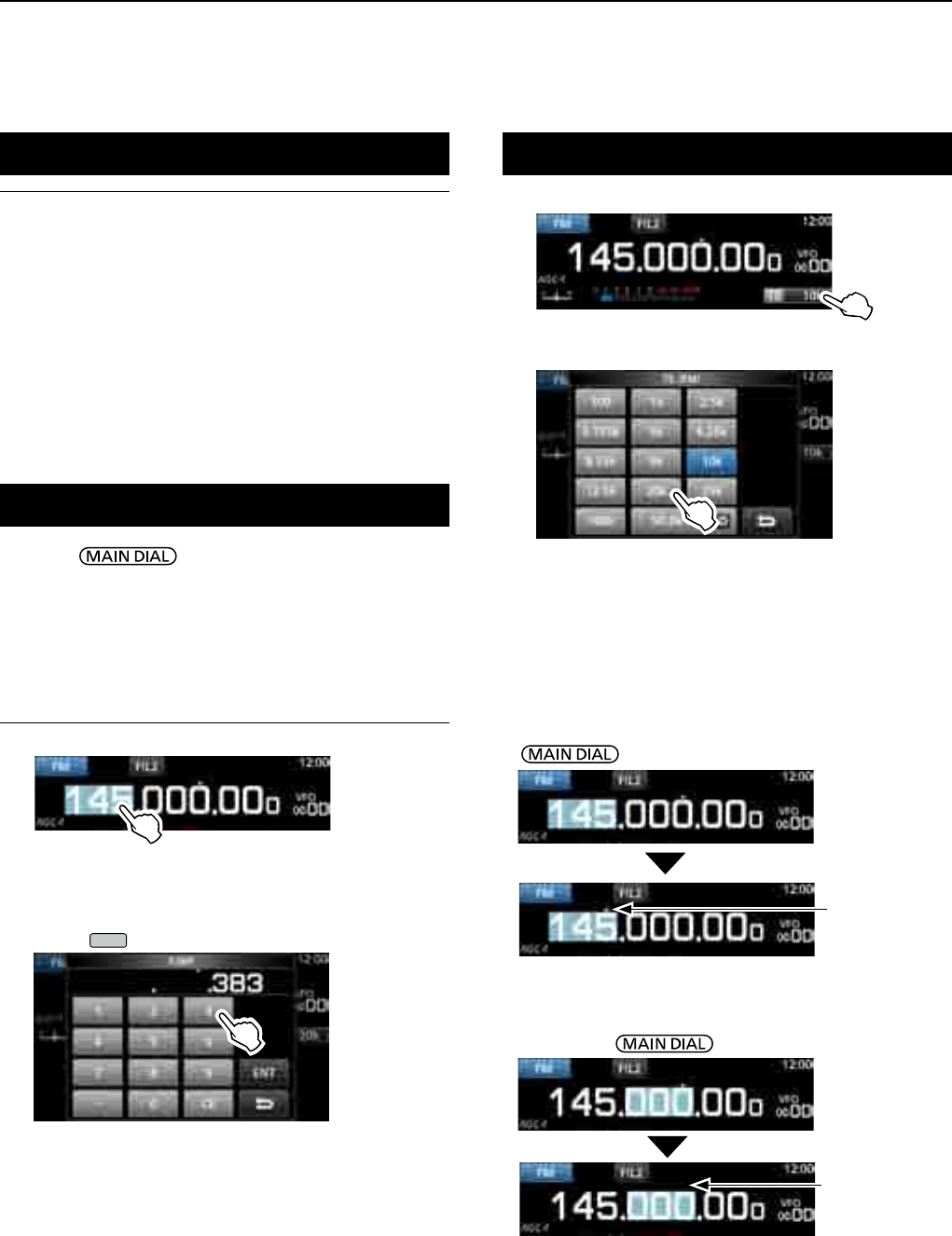
Setting the frequency
zRotate to set the receive frequency.
• The displayed frequency changes depending on the
selected tuning step.
DDirectly entering a frequency
You can set the frequency with the keypad.
Example: Entering 383.000000 MHz
1. Touch the MHz digits.
2. Start entry with the MHz digits.
LTo clear the entry, touch [CE].
L To clear the entry and return to the previous screen,
push
EXIT
.
3. Touch [ENT] to set the entered frequency.
• Closes the F-INP screen.
L If you touch [ENT] when the digits under 100 kHz are
not entered, “0” will be automatically entered into the
blank digits.
Entry examples
• 14.025000 MHz: [1], [4], [•], [0], [2], [5], [ENT]
• 21.240000 MHz: [2], [1], [•], [2], [4], [ENT]
• 14 MHz: [1], [4], [ENT]
• 150 kHz: [0], [•], [1], [5], [ENT]
• Changing from 21.240000 MHz to 21.360000 MHz:
[•], [3], [6], [ENT]
(You can omit MHz digit entry.)
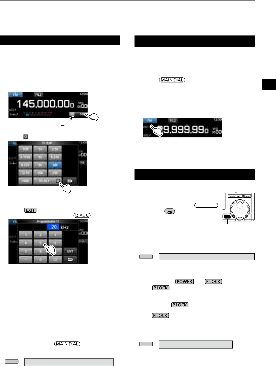
Changing the Tuning Step
Selecting the receiving mode (continued)
1. Touch the TS indicator.
2. Touch to select the tuning step. (Example: 20k)
•
The tuning step is set and returns to the previous screen.
LnformationL
• S (Synchronous)-AM mode:
The Synchronous AM demodulation is a receive method that
mixes the incoming signal with a pure carrier frequency with
no level variation, then extracts one of the two sides (USB or
LSB) signal which is free from interferences.
This method is effective to reduce the distortions due to
fading, or interferences from adjacent stations.
•When the "D-STAR" and "FM" icons alternately blink:
Indicates that an FM signal is being received while in the
Digital (D-STAR) mode.
DAbout the Tuning Step (TS) function
By turning the Tuning Step function ON or OFF, you can
change the frequency in MHz steps or 10 Hz.
Changing the frequency in MHz steps:
z Touch the MHz digit for 1 second, then rotate
.
Changing the frequency in 10 Hz steps:
z Touch the kHz digit to turn OFF the TS function,
then rotate .
L To set the frequency in 1 Hz steps, directly enter the
frequency with the keypad.
The Tuning Step
function is ON.
The Tuning Step
function is OFF.
3
BASIC OPERATION
1
2
3
4
5
6
7
8
9
10
11
12
13
14
15
16
17
18
19
20
21
3-3
Selecting the antenna
D About the Programmable Tuning Step
function
You can preset the tuning step between 0.1 kHz and
999.9 kHz in 100 Hz steps.
1. Touch the TS indicator.
2. Touch (Programmable TS icon).
The IC-R8600 has three antenna connectors: ANT1,
ANT2, and ANT3. You can use either ANT1, ANT2, or
ANT3 for receiving below 30 MHz.
1. Rotate to set a frequency to below
30 MHz (10 kHz–29.999999 MHz).
• The selected antenna connector indicator appears
under the receiving mode icon.
2. Touch the antenna connector indicator.
• Each touch changes the selected antenna connector
(ANT1, ANT2 and ANT3).
L Next time you set the same frequency, the same
antenna connector is automatically selected.
Dial/Panel Lock function
DDial Lock function
The Dial Lock function electronically locks
the dial to prevent frequency changes
caused by accidently moving
MAIN DIAL
.
z Hold down
SPEECH
for 1 second to turn
the Dial Lock function ON or OFF.
• The [LOCK] LED lights while the
function is ON.
• This function does not work when the
MENU, FUNCTION, QUICK menu,
Set mode or Scan Start screen is displayed.
LYou can change this setting on the MENU screen.
MENU
» SET > Function >
[SPEECH/LOCK] Switch
DPanel Lock function
The Panel Lock function locks all the controls on the
front panel except and .
z Push to turn the Panel Lock function ON or
OFF.
LP.LOCK indicator lights while the panel is locked.
• Holding down for 1 second turns the Dial Lock
function ON, and turns OFF the display.
• The indicator lights while the function is ON.
• This function does not work when the MENU,
FUNCTION, QUICK menu, Set mode or Scan Start
screen is displayed.
LYou can set to lock only keys on the MENU screen.
MENU
» SET > Function > P.LOCK Key
DAbout the Auto Tuning Step function
When you rapidly rotate , the tuning speed
automatically accelerates.
LYou can change this setting on the MENU screen.
MENU
» SET > Function > MAIN DIAL Auto TS
3. Start entry with the kHz digits.
(Example: 20.5 kHz)
LTo clear the entry, touch [CE].
LPush to chancel the entry.
LYou can also enter by rotating .
Changing the Tuning Step (Continued)
4. Touch [ENT] to set the entered frequency.
• Closes the Programmable TS screen.
Entry examples
• 14.2 kHz: [1], [4], [•], [2], [ENT]
• 14.0 kHz: [1], [4], [ENT]
• 150 kHz: [1], [5], [0], [ENT]
• Change 14.2 kHz to 14.5 kHz:
[•], [5], [ENT]
(You can omit kHz digit entry.)
長く押す
白色に点灯
Lights white
Hold down for
1 second
TS indicator
3BASIC OPERATION
3-4
1. Push .
• Opens the setting menu.
2. Touch [BACKLIGHT].
• Settable range: 0 (dark) ~ 100% (bright)
Adjusting Backlight dimmer
3. Rotate to adjust the brightness.
L You can reset to the default setting on the MENU
screen.
MENU
» SET > Display > LCD Backlight
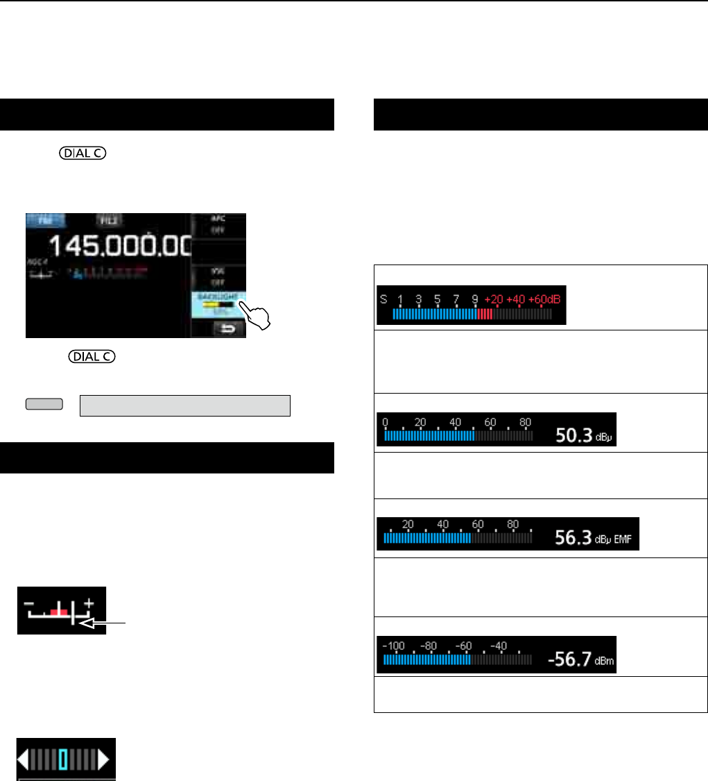
Selecting meter display
You can display one of the 4 different receive signal
parameters.
z Touch the meter to select the parameter you want to
display.
LYou can select the meter display also on the QUICK menu.
Fine tuning
D
When receiving FM, WFM or DIGITAL signal
You can have a ne tuning into the signal by setting
the marker on the tuning indicator to the center
position.
L In the WFM mode and when the AFC function is ON, the
marker may not be steady in the center position.
DWhen receiving FSK signal
You can have a ne tuning into the signal by tuning to
where both “◄” and “►” are displayed in the tuning
indicator.
Tuning marker
•S-meter: Received signal strength
Relative signal strength represented by S1 to S9. (in 6 dB steps)
At S9, the input signal level is 50µV (34 dBµ).
At S9 +20 dB, the input signal level is 54 dBµ.
•dBµ meter: Absolute voltage (Terminated)
0 dBµ is the level corresponding to 1 µV that is produced
on a 50
Ω
terminated load.
•dBµ EMF meter: Absolute voltage (Opened)
EMF (Electro Motive Force) is the unit of voltage produced
at an opened terminal.
LIndicated in 6 dB higher than a 50 Ω terminated load.
•dBm meter: Absolute power
0 dBm is the level corresponding to 1 mW that is produced
at a 50
Ω
terminated load.
DMeter display types
4
SCOPE OPERATION
1
2
3
4
5
6
7
8
9
10
11
12
13
14
15
16
17
18
19
20
21
4-14-1
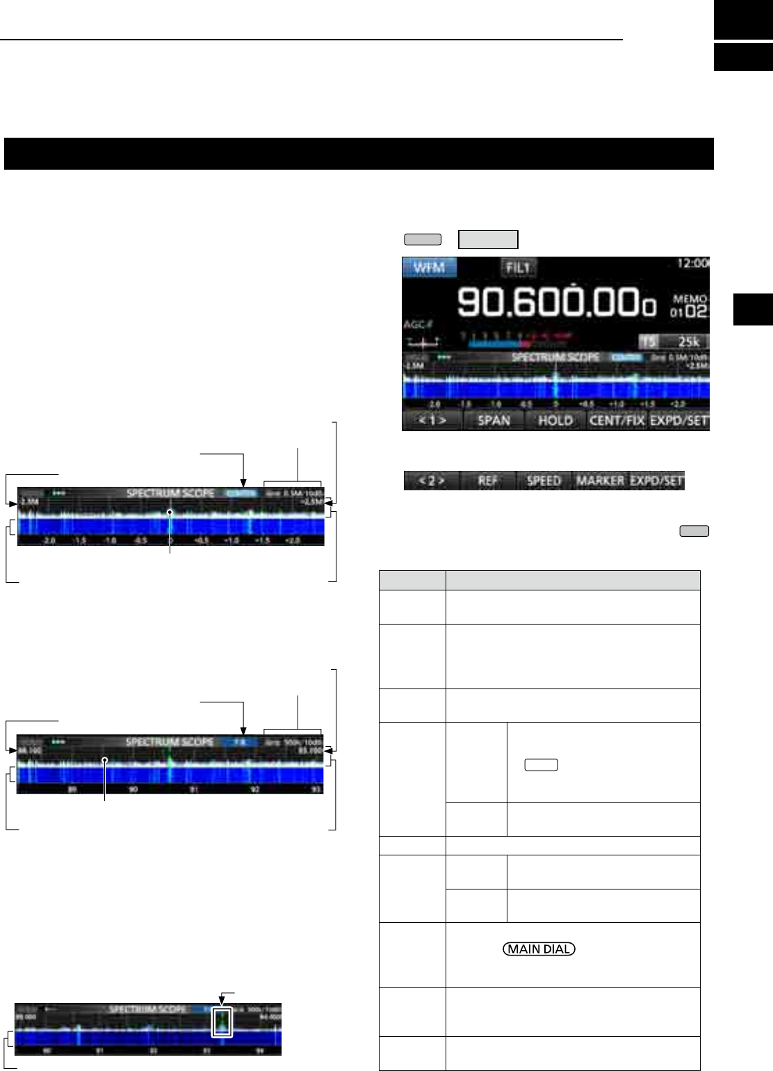
Spectrum scope screen
This spectrum scope enables you to display the
activity on the selected frequency range, as well as
the relative strengths of various signals.
The IC-R8600 has two spectrum scope modes. One is
the Center mode, and another one is the Fixed mode.
You can also turn the Waterfall display ON or OFF.
In addition, you can select a Mini scope screen to
save screen space.
DUsing the Spectrum Scope
1. Open the SPECTRUM SCOPE screen.
MENU
» SCOPE
• Center mode screen
The operating frequency is always displayed in the
center of the screen.
• Fixed mode screen
The activity on the selected frequency range can
easily be observed using this mode.
FFT scope zone
(FFT: Fast Fourier Transform)
FFT scope zone
Span (Display range)
Edge (Upper frequency)
Span (Display range)
Edge (Lower frequency)
Waterfall zone
Waterfall zone
Grid (frequency/level)
Grid (frequency/level)
Center mode icon
Fixed mode icon
Display frequency stays on Center
Display frequency moves
SPECTRUM SCOPE screen
Function menu (Menu 2)
zTouch <1> to switch to Menu 2.
DRX Marker
In the Fixed mode,
the RX Marker always marks the
receive frequency on the SPECTRUM SCOPE screen.
L The marker marks the receive frequency even during
peak hold.
LThe RX Marker is not displayed in the Center mode.
L When changing the frequency, the Waterfall maker is
displayed on the Waterfall zone.
RX Marker (green)
2. To exit the SPECTRUM SCOPE screen, push
EXIT
.
[Function menu keys]
Key Action
< 1 >
< 2 >
Toggles the Function menu between Menu 1
and Menu 2.
SPAN
In the Center mode, selects the scope span.
• Selectable spans: ±2.5, 5.0, 10, 25, 50,
100, 250, 500 kHz,
1.0 MHz and 2.5 MHz
EDGE In the Fixed mode, selects the Edge
frequencies.
HOLD
Touch
Turns the Peak Hold function ON
or OFF.
• “
HOLD
” and the Marker are
displayed. Freezes the current
spectrum.
Touch for
1 second
Clears the Peak Hold level
display.
CENT/FIX Selects the Center or Fixed mode.
EXPD/
SET
Touch Selects the Expanded or Normal
screen.
Touch for
1 second
Opens the SCOPE SET screen.
REF
Opens the Reference level window.
L Rotate to adjust the
Reference level.
L Touch again to close the window.
SPEED
Selects the sweep speed.
• “,” “,” or “” indicates FAST, MID, or
SLOW.
PEAK Displays the function keys for the Peak
Search function. (p. 4-3)
Waterfall zone
4SCOPE OPERATION
4-2
Spectrum scope screen (Continue)
DSetting the span
Set the frequency range around the receive frequency.
Settable span:
±2.5, 5.0, 10, 25, 50, 100, 250, 500 kHz, 1.0 and 2.5 MHz.
1. Open the SPECTRUM SCOPE screen.
MENU
» SCOPE
2. Touch [CENT/FIX] to select the Center mode.
•
Each touch changes between the Center and Fixed mode.
3. Touch [SPAN].
4. Touch [–] or [+].
• The span range changes.
5.
To exit the SPECTRUM SCOPE screen, push
several times.
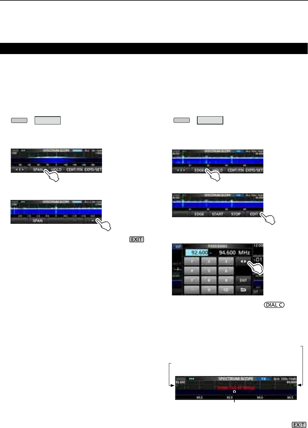
DSetting the range
The signals within a specied frequency range are
displayed.
Settable range: 0.010 ~ 3000.000 MHz.
1. Open the SPECTRUM SCOPE screen.
MENU
» SCOPE
2. Touch [CENT/FIX].
•
Each touch changes between the Center and Fixed mode.
3. Touch [EDGE].
4. Touch [EDIT].
5. Touch [] to select the upper or lower edge.
• The selected frequency edge is highlighted.
6. Touch the numeric keys, or rotate to
change the frequency, then touch [ENT].
L When the operating frequency moves outside
the upper or lower Edge frequency, “<<” or “>>”
is displayed in the upper side corners of the
SPECTRUM SCOPE screen.
7.
To exit the SPECTRUM SCOPE screen, push
several times.
"<<" blinks when the frequency is outside
the lower edge (Example: 92.600).
">>" blinks when the frequency is outside
the higher edge (Example: 94.600).
When the frequency goes further away,
“Scope Out of Range” is displayed.
4
SCOPE OPERATION
1
2
3
4
5
6
7
8
9
10
11
12
13
14
15
16
17
18
19
20
21
4-3
DTouch screen operation
When you touch the FFT scope zone or the waterfall
zone on the SPECTRUM SCOPE screen, the area will
be zoomed in. Then, touch the signal in the zoomed
area to tune into the signal on the SPECTRUM
SCOPE screen.
1. Open the SPECTRUM SCOPE screen.
MENU
» SCOPE
2. Touch the Scope screen.
• The area around the touched point is zoomed in.
L
Touch out of the zoomed area to close the zoomed
window.
3. Touch the signal in the zoomed area.
• The receiving frequency is tuned into the touched
signal frequency.
4. To exit the SPECTRUM SCOPE screen, push .
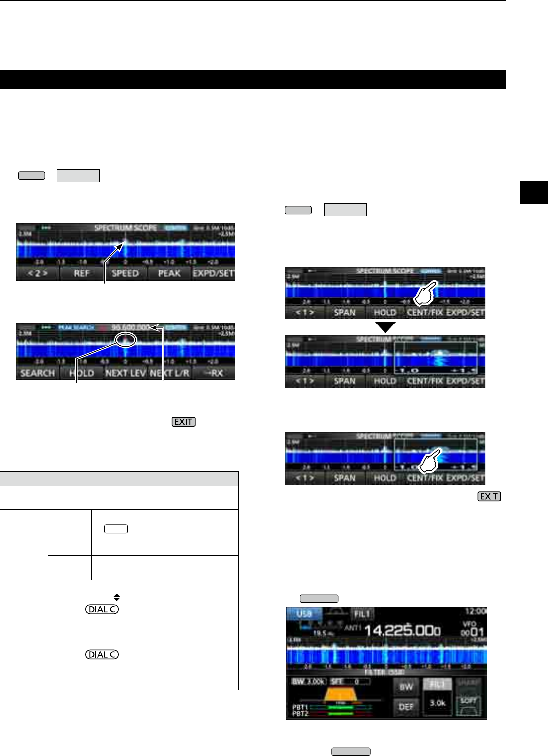
DSearching for the peak signal
You can nd the strongest signal within the scope
frequency range.
1. Open the SPECTRUM SCOPE screen.
MENU
» SCOPE
2. Touch [<1>] to select the [<2>] menu.
L Each touch toggles between menu [<1>] and [<2>].
3. Touch [PEAK].
• The Peak Pointer appears on the strongest signal
frequency within the scope frequency range.
4. To exit the peak search menu, push .
Spectrum scope screen (Continue)
[Search menu keys]
Key Action
SEARCH Touch to put the peak pointer on the strongest
signal frequency.
HOLD
Touch
Turns the Hold function ON or OFF.
• “ HOLD ” and the Marker are
displayed. Freezes the current
spectrum.
Touch for
1 second Clears the Peak Hold level.
NEXT
LEV
Enters to the Next Peak level mode.
• Popup “NEXT ” is displayed.
• Rotate to search for the next peak
in level.
NEXT L/R
Enters to the Peak Select mode.
• Popup “NEXT ” is displayed.
• Rotate to select the next peak.
→RX Touch for 1 second to tune the frequency to
the current peak level signal.
DMini scope screen
The Mini scope screen can be simultaneously
displayed with another function display, such as the
FSK DECODE screen.
z
Push
M.SCOPE
to turn the Mini scope screen ON or OFF.
L Hold down
M.SCOPE
for 1 second to display the
SPECTRUM SCOPE screen.
Mini scope screen (with the Filter setting screen)
The strongest signal
The strongest signal Signal frequency
Peak search mode
4SCOPE OPERATION
4-4
Spectrum scope screen (Continue)
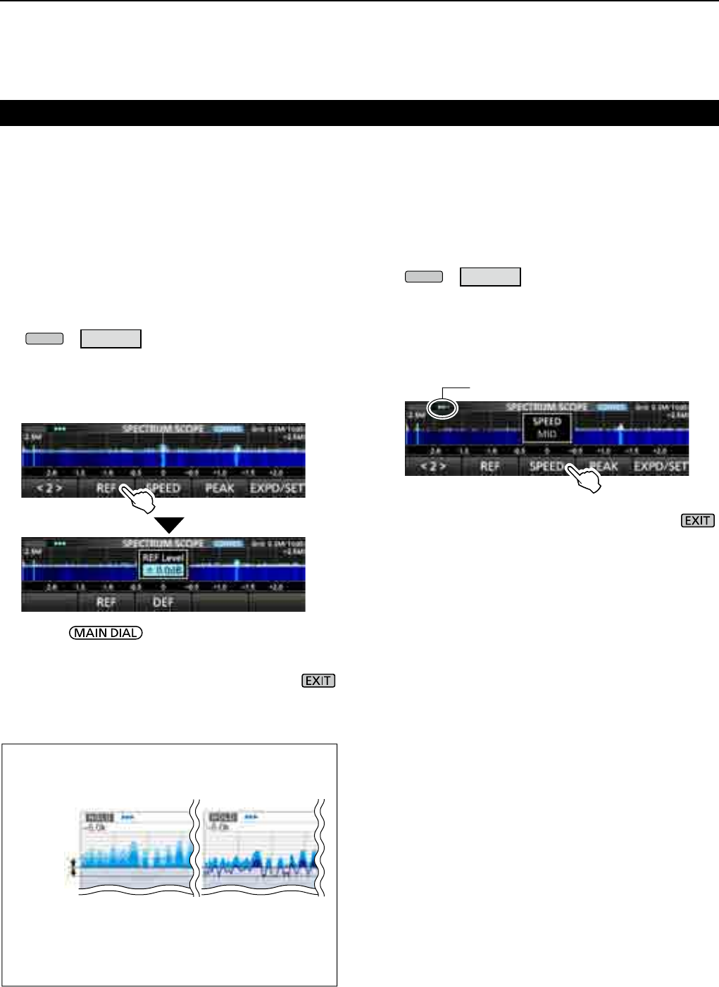
DAdjusting the Reference level
Adjusting the Reference level of the screen helps you
to see a weak signal that is buried in the noise oor.
• Even if this setting is changed, it does not affect the scope
input level.
• When you adjust the Reference level, the signal strength
for the waterfall also appears to change.
Settable range: –20.0 dB ~ +20.0 dB
1. Open the SPECTRUM SCOPE screen.
MENU
» SCOPE
2. Touch [<1>].
• The function menu changes to Menu 2.
3. Touch [REF].
LEach touch opens and closes the window.
4. Rotate to adjust the level.
LTouch [DEF] for 1 second to reset to ±0.0 dB.
LTouch [REF] to return to Menu 2.
5.
To exit the SPECTRUM SCOPE screen, push
several times.
Difference in spectrum display
Reference level
(+20.0 dB)
Reference level
(–20.0 dB)
L If you adjust this setting to a positive level, all signal
levels appear stronger.
Or, if you adjust to a negative level, all signal levels
appear weaker.
±0.0 dB
+20.0 dB
–20.0 dB
DSweep speed
Select the sweep speed to change the FFT scope
refresh interval and the waterfall speed.
L To change only the waterfall speed, select “Slow,” “Mid,”
or “Fast” on the Scope set screen. (p. 4-6)
1. Open the SPECTRUM SCOPE screen.
MENU
» SCOPE
2. Touch [<1>].
• The function menu changes to Menu 2.
3. Touch [SPEED] several times to select
FAST, MID
and SLOW
.
L Each touch changes the speed.
4.
To exit the SPECTRUM SCOPE screen, push .
“” (MID), “” (SLOW) or “” (FAST)
4
SCOPE OPERATION
1
2
3
4
5
6
7
8
9
10
11
12
13
14
15
16
17
18
19
20
21
4-5
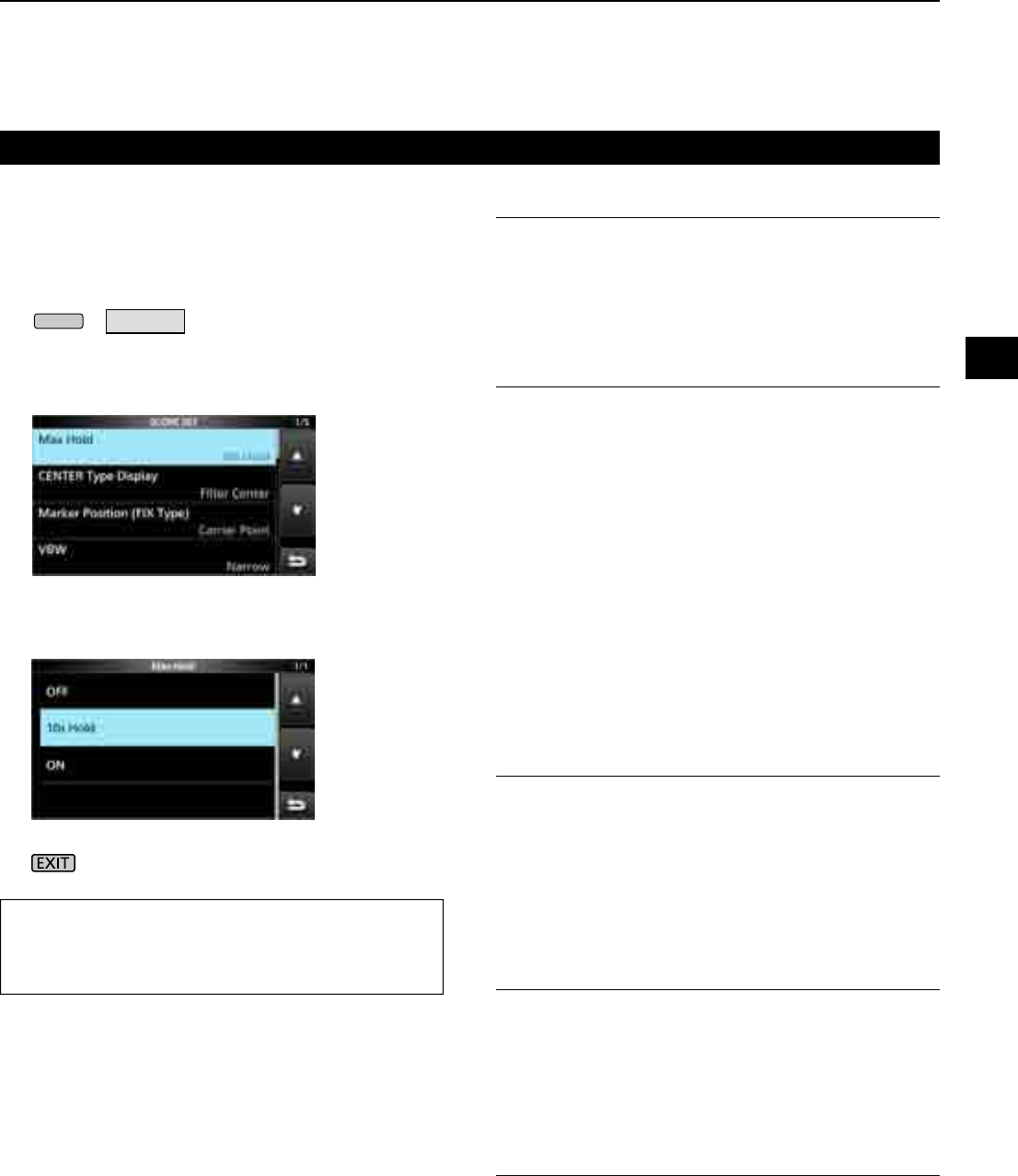
DScope set screen
The Scope Set screen is used to congure the scope
screen parameters, such as the waveform color.
1. Open the SPECTRUM SCOPE screen.
MENU
» SCOPE
2. Touch [EXPD/SET] for 1 second.
• Opens the SCOPE SET window.
3. Select the desired item.
4. Select the option or set the level.
L See to the right for details of the setting items and
their options.
5. To exit the SPECTRUM SCOPE screen, push
several times.
Spectrum scope screen (Continue)
TIP: How to reset to the default setting
Touching the item or its option for 1 second displays
the Quick menu, and then touch “Default” to reset to
the default setting.
Max Hold (Default: 10s Hold)
Select the peak level holding function.
• OFF: Turns OFF the peak level holding
function.
• 10s Hold: Holds the peak spectrum for 10 seconds.
• ON: Turns ON the peak spectrum.
CENTER Type Display (Default: Filter Center)
Select the center frequency of the SPECTRUM
SCOPE screen. (Only in the Center mode)
• Filter Center: Displays the selected lter’s center
frequency in the center of the
SPECTRUM SCOPE screen.
• Carrier Point Center:
Displays the carrier point frequency
of the selected operating mode in the
center of the SPECTRUM SCOPE
screen.
• Carrier Point Center (Abs. Freq.*):
In addition to the carrier point center
setting above, the actual frequency is
displayed at the bottom of the scope.
*Abs. Freq. : Absolute Frequency
Marker Position (Fix Type) (Default: Carrier Point)
Select the marker position on the SPECTRUM
SCOPE screen. (Only in the Fixed mode)
• Filter Center: Displays the Marker on the selected
lter’s center frequency.
• Carrier Point: Displays the Marker on the carrier
point frequency of the selected
operating mode.
VBW (Default: Narrow)
Select the Video Band Width (VBW).
• Narrow: Sets the VBW to narrow.
• Wide: Sets the VBW to wide.
L When “Wide” is selected, the line drawn on the receive
spectrum becomes wide. However, the small edge cannot
be drawn.
Averaging (Default: OFF)
Set the FFT scope waveform averaging function to
between 2 and 4, or OFF.
• OFF: The FFT scope screen refreshes at each
sweep time. This setting displays the
critical spectrum view.
• 2, 3, 4: The FFT scope screen averages 2
to 4 sweeps to smoothly display the
spectrum.
4SCOPE OPERATION
4-6
Spectrum scope screen (Continue)
DScope set screen (Continued)
Waveform Type (Default: Fill)
Select the outline waveform display for the FFT scope
screen.
• Fill: The waveform is drawn only in color.
•
Fill + Line:
The waveform is drawn in color with an outline.
Waveform Color (Current)
(Default: (R) 172 (G) 191 (B) 191)
Set the waveform color for the currently received signals.
L Touch and select the color scale, and then rotate .
Waveform Color (Line) (Default: (R) 56 (G) 24 (B) 0)
Set the waveform outline color for the currently
received signals.
L Touch and select the color scale, and then rotate .
Waveform Color (Max Hold)
(Default: (R) 45 (G) 86 (B) 115)
Set the waveform color for the received signals
maximum level.
L Touch and select the color scale, and then rotate .
Marker Color (RX) (Default: (R) 0 (G) 180 (B) 0)
Set the pointer color for the RX Marker in the Fixed mode.
L Touch and select the color scale, and then rotate .
Marker Color (Peak) (Default: (R) 238 (G) 17 (B) 34)
Set the pointer color for the Peak Marker.
L Touch and select the color scale, and then rotate .
Waterfall Display (Default: ON)
Turn the Water fall display ON or OFF for the normal
scope or Mini scope screens.
• OFF: Turns OFF the Waterfall display.
• ON: Turns ON the Waterfall display.
L In the Expanded scope screen, the Waterfall is always
displayed.
Waterfall Speed (Default: Mid)
Select the Waterfall speed.
• Slow: Sets the waterfall speed to Slow.
• Mid: Sets the waterfall speed to Mid.
• Fast: Sets the waterfall speed to Fast.
Waterfall Size (Expand Screen) (Default: Mid)
Select the Waterfall height for the Expand scope screen.
• Small: The same height with the Normal scope
screen, only the FFT scope expands.
• Mid: The Waterfall height expands at the same
ratio with the FFT scope.
• Large: Only the Waterfall height expands.
Waterfall Peak Color Level (Default: Grid 8)
Select the signal level that the Waterfall displays
a peak color. Higher signal levels are Red, Yellow,
Green, Light-blue, Blue and Black, in that order.
• Option: Grid 1 ~ Grid 8
Waterfall Marker Auto-hide (Default: ON)
Set the Waterfall Marker Auto-hide function to ON or OFF.
• OFF: The marker in the Waterfall zone stays ON.
• ON: The marker in the Waterfall zone is hidden
2 seconds after you have stopped it in place.
Peak Excursion (Default: 6dB)
Set the difference of amplitude between the peak
signal and nearby signals that determines what is
considered a "peak."
• Settable range: 0 dB ~ +60 dB
Peak Threshold (Default: –70dB)
Set the threshold level for the Peak signal detection.
• Settable range: –80 dB ~ 0 dB
Peak Search Target Type (Default: Current)
Select the spectrum waveform type to search.
• Current: Search signals in the current
waveform.
• Max Hold: Search signals in the peak hold
waveform.
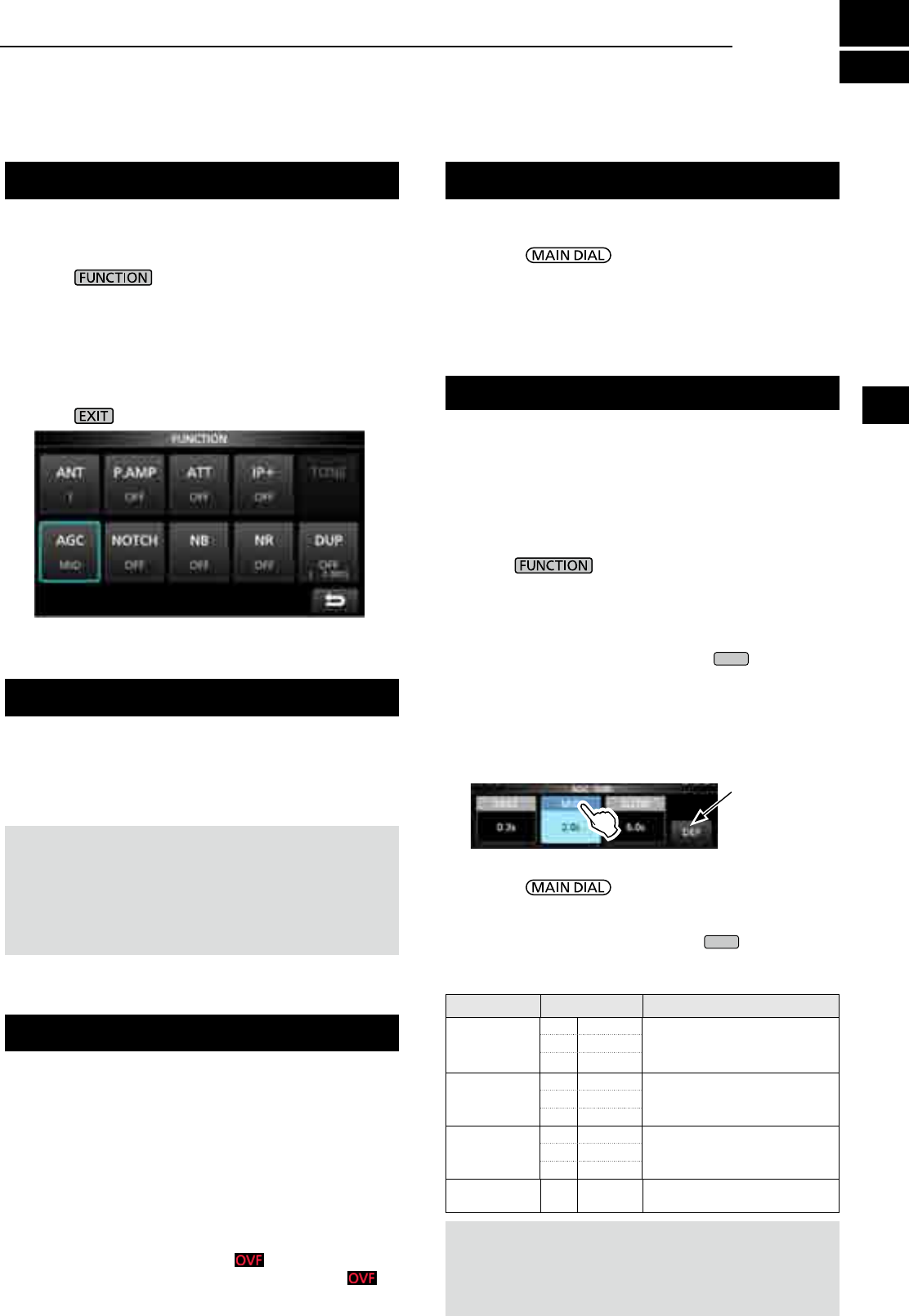
5
OTHER FUNCTIONS
1
2
3
4
5
6
7
8
9
10
11
12
13
14
15
16
17
18
19
20
21
5-1
Preamplier
About the Function screen
A preamplier is used when receiving weak signals.
LEach band memorizes the preamplier setting.
zPush [P.AMP] on the Function screen.
L Each touch turns the preamp ON or OFF.
On the Function screen, you can congure the
settings of various functions for each receiving mode.
1. Push to open the Function screen.
2. Touch (or touch for 1 second) a function key.
• Each touch turns the function ON or OFF.
• Each long touch selects an option for the
function.
L The usable functions differ, depending on the
receiving mode.
3. Push to close the Function screen.
NOTE:
The gain of preamplier is approximately 20 dB on
the HF bands, 14 dB on the VHF and UHF bands.
When you use the preamplier while receiving a
strong signal, the receiving signal may be distorted.
In such case, turn OFF the preamplier.
Attenuator
The Attenuator prevents a desired signal from
becoming distorted when a very strong signal is near
the frequency, or when a very strong electric eld.
LEach band memorizes the Attenuator setting.
z Touch [ATT] on the Function screen, to turn ON the
Attenuator.
L Each touch changes the attenuation between 10 dB
(ATT10), 20 dB (ATT20), 30 dB (ATT30) and OFF (no
indication).
L If a strong signal is received and (Overow) appears,
reduce the RF gain or turn ON the attenuator until
disappears.
Function screen example (in the CW mode)
The AGC (Automatic Gain Control) produces a
constant audio output level, even when the received
signal strength varies greatly.
The receiver has 3 preset AGC settings (time
constants: FAST, MID and SLOW) for all modes
except the FM and DIGITAL mode.
1. Select the operating mode. (Example: SSB)
2. Push to open the FUNCTION screen.
3. Touch [AGC] to select an AGC setting.
• Each touch changes the attenuation between FAST
("AGC-F"), MID and SLOW.
L
The AGC is xed to "FAST" in the FM, WFM or Digital mode.
4. To close the FUNCTION screen,
EXIT
.
You can change the preset AGC time constant:
1.
On the FUNCTION screen, touch [AGC] for 1 second.
2. Touch either FAST, MID or SLOW.
3. Touch an AGC preset you want to change the time
constant. (Example: MID)
4. Rotate to set the time constant.
L The adjustable time constants are described in the
table below.
5. To close the AGC screen, push
EXIT
.
•Selectable AGC Time constant (unit: seconds)
Mode Default Adjustable time constant
SSB
0.3 (FAST) OFF, 0.1, 0.2, 0.3, 0.5, 0.8, 1.2,
1.6, 2.0, 2.5, 3.0, 4.0, 5.0 or 6.0
2.0 (MID)
6.0 (SLOW)
CW/FSK
0.1 (FAST) OFF, 0.1, 0.2, 0.3, 0.5, 0.8, 1.2,
1.6, 2.0, 2.5, 3.0, 4.0, 5.0 or 6.0
0.5 (MID)
1.2 (SLOW)
AM
3.0 (FAST) OFF, 0.3, 0.5, 0.8, 1.2, 1.6, 2.0,
2.5, 3.0, 4.0, 5.0, 6.0, 7.0 or 8.0
5.0 (MID)
7.0 (SLOW)
FM/WFM/
DIGITAL 0.1 (FAST) Fixed
AGC screen (in the SSB mode)
You can reset
to the default
settings by
touching this key
for 1 second.
AGC function control
NOTE:
When you are receiving weak signals, and a strong
signal is momentarily received, the AGC function quickly
reduces the receiver gain. When that signal disappears, the
receiver may not receive the weak signal because of the AGC
action. In that case, select FAST, or turn OFF the AGC function.
Selecting the antenna
You can use either ANT1, ANT2, or ANT3 for receiving
below 30 MHz.
1. Rotate to set a frequency to below
30 MHz (10 kHz ~ 29.999999 MHz).
2. Touch the antenna connector indicator.
• Each touch changes the selected antenna connector.
L Next time you set the same frequency, the same
antenna connector is automatically selected.
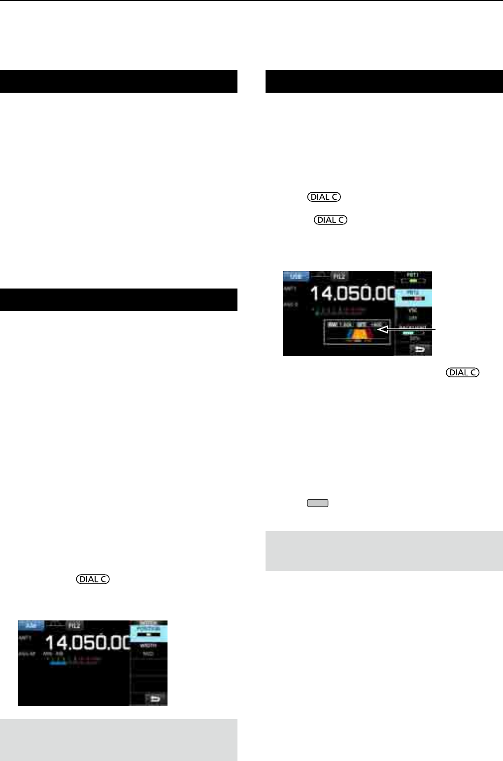
5OTHER FUNCTIONS
5-2
Using the Digital Twin PBT
SSB, CW, FSK and AM modes
The Digital Twin PBT (Passband Tuning) electronically
narrows the IF passband width by over wrapping the
passband frequency ranges of 2 PBT lters (PBT1
and PBT2), to reject interference. The IC-R8600 uses
DSP for the PBT function.
1. Push .
2. Touch [PBT1] or [PBT2].
3. Rotate to adjust the passband width.
• The current passband width (BW) and shift frequency
(SFT) is displayed.
L A dot is displayed right below the shift frequency
indicates that the passband frequency is shifted.
• To narrow the IF passband width, rotate to
shift the passband width in the opposite direction from
each other.
• To shift the pass band frequency range, match both
the [PBT1] and [PBT2].
• The PBT is adjustable in 50 Hz steps in the SSB, CW,
and FSK modes, and 200 Hz in the AM mode. In this
case, the center shift frequency changes in 25 Hz
steps in the SSB, CW, and FSK modes, and 100 Hz in
the AM mode.
• Touch [PBT1] or [PBT2] for 1 second to clear the PBT
setting.
4. Push
EXIT
to close the setting menu.
NOTE: While adjusting, you may hear noise. This comes
from the DSP unit and does not indicate an equipment
malfunction.
IP Plus function
The IP Plus function improves the Intermodulation
Distortion (IMD) quality by optimizing the direct
sampling system performance.
This function optimizes the Analog/Digital Converter
(ADC) against the distortion when you receive a
strong input signals. It also improves the Third-order
Intercept Point (IP3) while minimizing the reduction of
the receive sensitivity.
LEach band memorizes the ON/OFF setting.
zTouch [IP+] on the FUNCTION screen.
L Each touch turns the IP Plus function ON or OFF.
L Select ON to prioritize the IP quality, and select OFF
to prioritize the receive sensitivity.
Notch Filter
The notch lter suppresses interference.
Auto Notch automatically attenuates beat tones,
tuning signals and so on.
The Manual Notch attenuates beat tones, tuning
signals and so on by adjusting the notching width and
frequency.
Auto Notch: Used in the SSB, AM and FM modes.
Manual Notch: Used in the SSB, CW, FSK and AM
modes.
zTouch [NOTCH] on the FUNCTION screen.
• Each touch changes between “AN (Auto Notch),” “MN
(Manual Notch)” and OFF.
L In the CW or FSK mode, only Manual Notch (MN)
can be selected.
L In the FM or DIGITAL mode, only Auto Notch (AN)
can be selected.
D
Setting the notching width and frequency
1. Touch [NOTCH] for 1 second.
LThe Notch setting menu is displayed.
2. Slowly rotate to adjust the notching
frequency on the POSITION scale.
3. Touch [WIDTH] to select the Manual Notch filter
width from “WIDE,” “MID” or “NAR.”
NOTE: While adjusting, noise may be heard.
This comes from the DSP unit and does not indicate
an equipment malfunction.
A dot is displayed
when the lter
frequency is shifted.
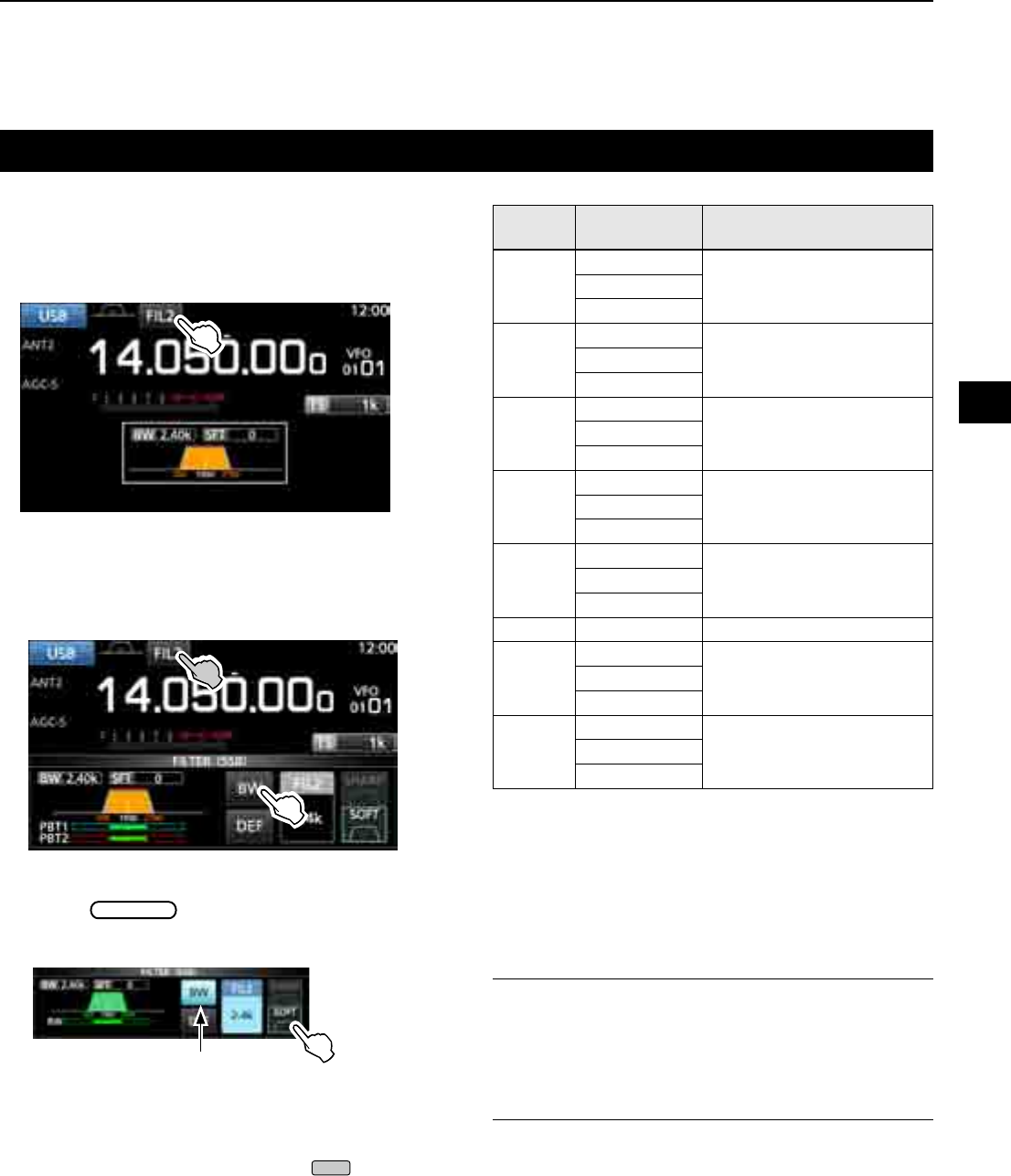
5
OTHER FUNCTIONS
1
2
3
4
5
6
7
8
9
10
11
12
13
14
15
16
17
18
19
20
21
5-3
Selecting the digital IF lter
The IC-R8600 has 3 digital IF lter passband widths for
each receive mode.
z Touch the lter icon several times to select FIL 1
(wide), FIL 2 (mid) or FIL 3 (narrow).
L Each touch changes the lter.
DAdjusting the passband width
1. Touch the filter icon for 1 second.
2. Touch [BW].
• Selects the passband width mode.
L You cannot change the passband width in the FM,
WFM or DIGITAL modes.
3. Rotate MAIN DIAL to adjust the passband width.
L When you change the passband width, the Twin PBT
setting is reset to the center position.
4. In the SSB or CW mode, you can change the filter
shape by touching [SHARP] or [SOFT].
LSee "Selecting the lter shape" to the right.
5. To close the FILTER screen, push
EXIT
several
times.
Mode IF lter
(default) Selectable range (steps)
SSB
FIL 1 (3.0 kHz)50 Hz to 500 Hz (50 Hz)/
600 Hz to 3.6 kHz (100 Hz)
FIL 2 (2.4 kHz)
FIL 3 (1.8 kHz)
CW
FIL 1 (1.2 kHz)50 Hz to 500 Hz (50 Hz)/
600 Hz to 3.6 kHz (100 Hz)
FIL 2 (500 Hz)
FIL 3 (250 Hz)
FSK
FIL 1 (2.4 kHz)50 Hz to 500 Hz (50 Hz)
600 Hz to 2.7 kHz (100 Hz)
FIL 2 (500 Hz)
FIL 3 (250 Hz)
AM
S-AM
FIL 1 (9.0 kHz)
200 Hz to 10.0 kHz (200 Hz)FIL 2 (6.0 kHz)
FIL 3 (3.0 kHz)
FM
FIL 1 (50 kHz)
FixedFIL 2 (15 kHz)
FIL 3 (7.0 kHz)
WFM FIL 1 (200 kHz)Fixed
D-STAR
P25
NXDN-n
FIL 1 (15 kHz)
FixedFIL 2 (10 kHz)
FIL 3 (7.0 kHz)
dPMR
NXDN-vn
DCR
FIL 1 (10 kHz)
FixedFIL 2 (7.0 kHz)
FIL 3 (5.0 kHz)
DSelecting the lter shape
In the SSB or CW mode, you can independently
set the DSP lter shape to soft or sharp for each
operating mode.
SHARP
This selection is to emphasize the passband width
of the lter. The lter has an almost ideal shape
factor. Signals out of the passband are extremely
ltered out and it gives you better audio quality.
SOFT
The lter shoulders are roundly formed as in analog
lters. This decreases noise components in the
high and low frequencies of the lter passband and
increases the S/N ratio of the target signal. These
characteristics play an effective role in picking up
very weak signals. The lter shape is kept, and the
sharpness of the bandpass is excellent.
Passband width mode
[Receiving mode and the IF lter]
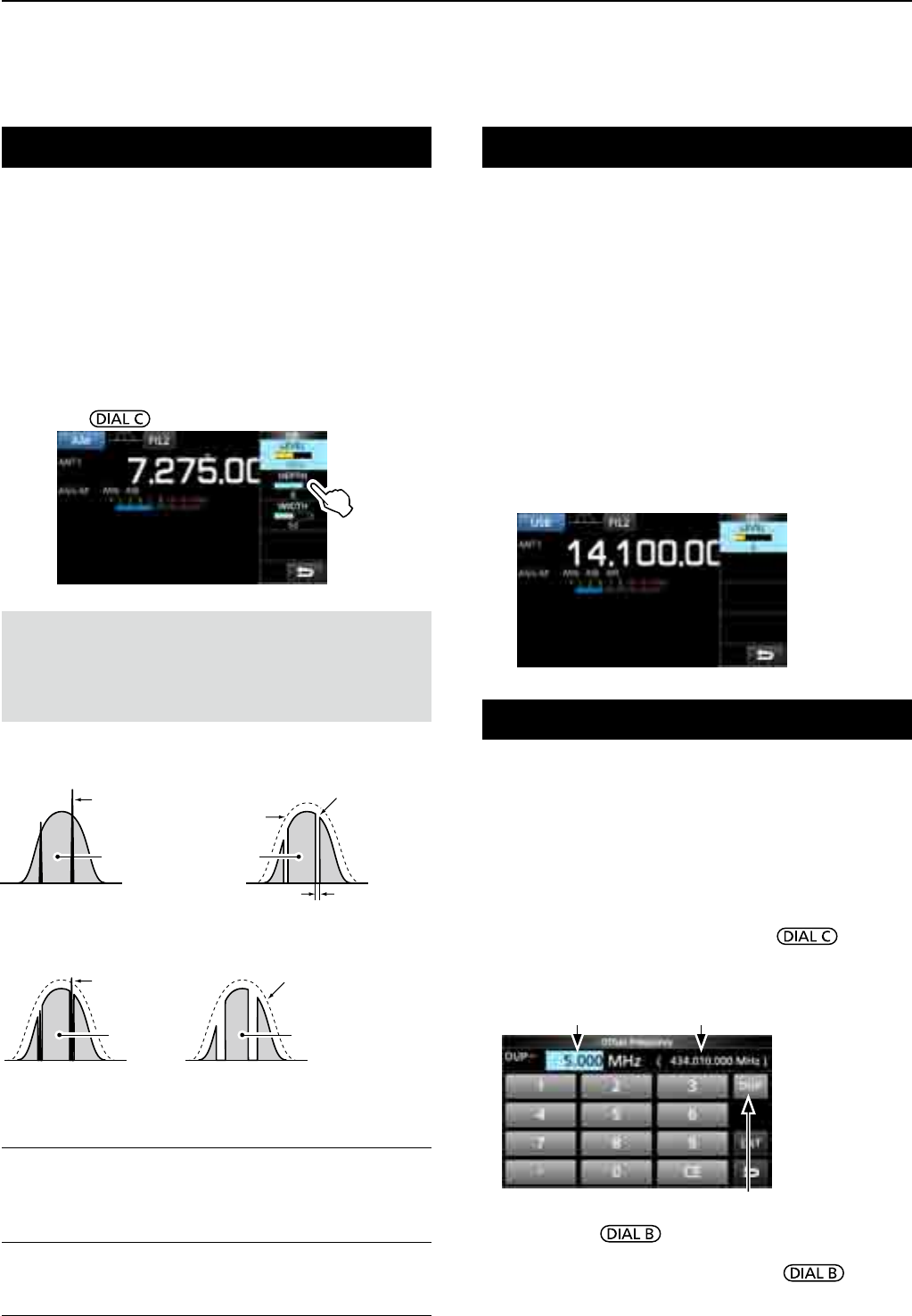
5OTHER FUNCTIONS
5-4
Noise Blanker (NB)
SSB, CW, FSK and AM modes
The Noise blanker eliminates pulse-type noise such
as the noise from car ignitions.
1. On the FUNCTION screen, touch [NB].
L
Each touch turns the Noise Blanker function ON or OFF.
2. To change the NB level, depth or width, touch
[NB] for 1 second.
• Turns ON the Noise Blanker and opens the NB menu.
3. Touch the adjusting item. (Example: DEPTH)
4. Rotate to adjust the level.
NOTE: When using the Noise Blanker, received signals
may be distorted if they are excessively strong or the noise
is other than a pulse type. In that case, turn the OFF Noise
Blanker, or shallow the DEPTH on the NB menu.
See the description below for details.
LEVEL (Default: 50%)
Set the Noise Blanker activation level to between 0
and 100%.
DEPTH (Default: 8)
Adjust the noise attenuation level between 1 and 10.
WIDTH (Default: 50)
Adjust the blanking duration time between 1 and 100.
Noise Reduction
The Noise Reduction function digitally reduces
random noise components, and enhances desired
signals that are buried in noise.
L The function is effective in the SSB, AM and CW modes.
1. On the FUNCTION screen, touch [NR].
LEach touch turns the Noise Reduction function ON or OFF.
2. To change the Noise Reduction level, touch [NR]
for 1 second.
• Turns ON the Noise Reduction and opens the NR menu.
3. Set the Noise Reduction level to between 0 and 15.
• Adjust the Noise Reduction level to where noise is
reduced and the received signal is not distorted.
L Set to a higher level to increase the reduction level,
and a lower level to decrease it.
Noise Blanker OFF Noise Blanker ON
Pulse-type
noise
Receive
signal
Noise Blanker ON
(Not enough DEPTH)
Noise Blanker ON
(WIDTH set too wide)
NB WIDTH
Receive
signal
LEVEL
Receive
signal
Receive signal
Pulse-type
noise remains
Part of the receive signal
is eliminated along with
pulse-type noise
Pulse-type
noise eliminated
Duplex operation
You can receive a communication that uses different
frequencies for transmitting and receiving (Duplex), by
setting the offset frequency and shift direction.
1. On the FUNCTION screen, touch [DUP].
• Each touch changes between [DUP–], [DUP+] and [OFF].
2. To change the frequency offset or shift direction,
touch [DUP] for 1 second.
3. Touch the numeric keys or rotate , to set
the frequency offset.
• Settable range: 0.000 ~ 200.000 MHz (1 kHz step)
Touch to change the Shift direction
Receive frequency
(When the Monitor function is ON.)
Offset frequency
4. Hold down to turn ON the Monitor function.
•
The receive frequency shifts according to the set frequency
offset and direction, while holding down .
• [DUP–] or [DUP+] blinks when the shifted frequency is
out of receive frequency range.
• The frequency offset and direction is stored in each
memory channel.
• When the frequency offset is set to 0.000 MHz, the
receive frequency is not shifted.
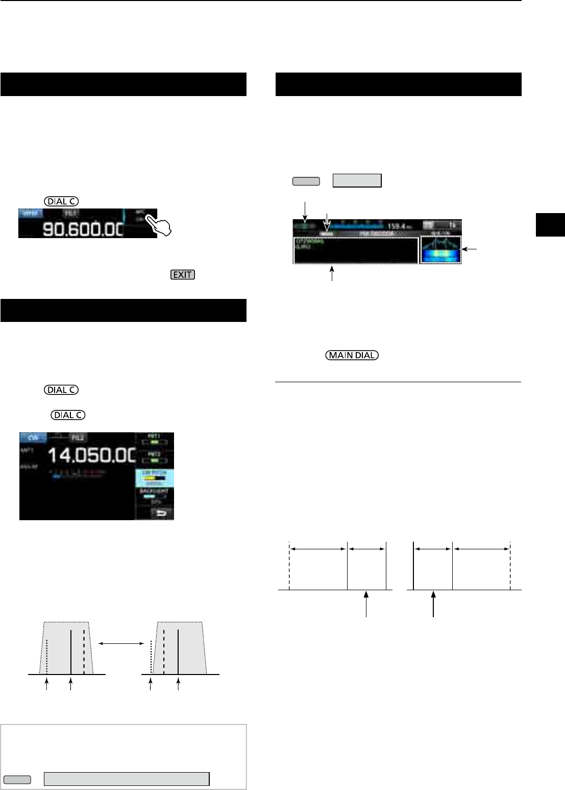
5
OTHER FUNCTIONS
1
2
3
4
5
6
7
8
9
10
11
12
13
14
15
16
17
18
19
20
21
5-5
AFC function
FM, WFM and DIGITAL modes
The AFC (Automatic Frequency Control) function
tunes the receive frequency into the incoming signal.
LThis function activates regardless of the squelch condition.
L In the WFM mode, the receive frequency may not tune to
the center frequency.
1. Push .
2. Touch [AFC].
• Each touch turns the AFC function ON or OFF.
3. To close the MENU screen, push .
Receiving in the CW mode
DSetting the CW pitch control
You can set the received CW audio pitch and the CW
side tone without changing the operating frequency.
1. Push .
2. Touch [CW PITCH].
3. Rotate to adjust the pitch.
• Settable range: 300 ~ 900 Hz
DAbout the CW Reverse mode
The CW-R (CW Reverse) mode reverses the receive
Beat Frequency Oscillator (BFO).
Use when interfering signals are near the desired
signal and you want to reduce interference.
CW mode (LSB side) CW-R mode (USB side)
BFO BFO
Interference Desired
signal
Interference Desired
signal
TIP: Reversing the carrier point
The carrier point of the CW mode is LSB by default.
You can change it to USB in the “CW Normal Side” item of
the OTHERS set screen. (p. 11-3)
MENU
» SET > Function > CW Normal Side
Receiving FSK (RTTY) signal
BFO BFO
170 Hz 1615 Hz170 Hz1615 Hz
FSK Normal mode FSK-R mode
SpaceMark Space Mark
DDecoded FSK data display
The IC-R8600 decodes FSK signals with a built-in
decoder.
The decoded characters are displayed on the
FSK DECODE screen.
zOpen the FSK DECODE screen in the FSK mode.
MENU
» DECODE
DDecoding FSK signal
1. Set the Mark frequency and Shift width on the
FUNCTION screen. (p. 5-7)
2. Rotate to adjust the waveform on the
FFT scope screen.
InformationL
• Aim for a symmetrical wave form, and be sure the peak
points align with the mark and shift frequency lines on
the FFT scope screen.
• The S-meter displays the received signal strength, when
a signal is received.
•
If you cannot decode correctly, try the FSK-R (Reverse) mode.
• Tune to where both “◄” and “►” are displayed in the
tuning indicator.
• The Mark and Shift frequency differ, depending on the
frequency band.
FFT scope
Tuning indicator
When tuned into an FSK signal, the decoded
characters are displayed here.
Decoding baud rate
L On the amateur radio band, set the Mark frequency to
2125 Hz and the shift frequency to 170 Hz in the FSK-R
mode.
Displayed
frequency
Displayed
frequency
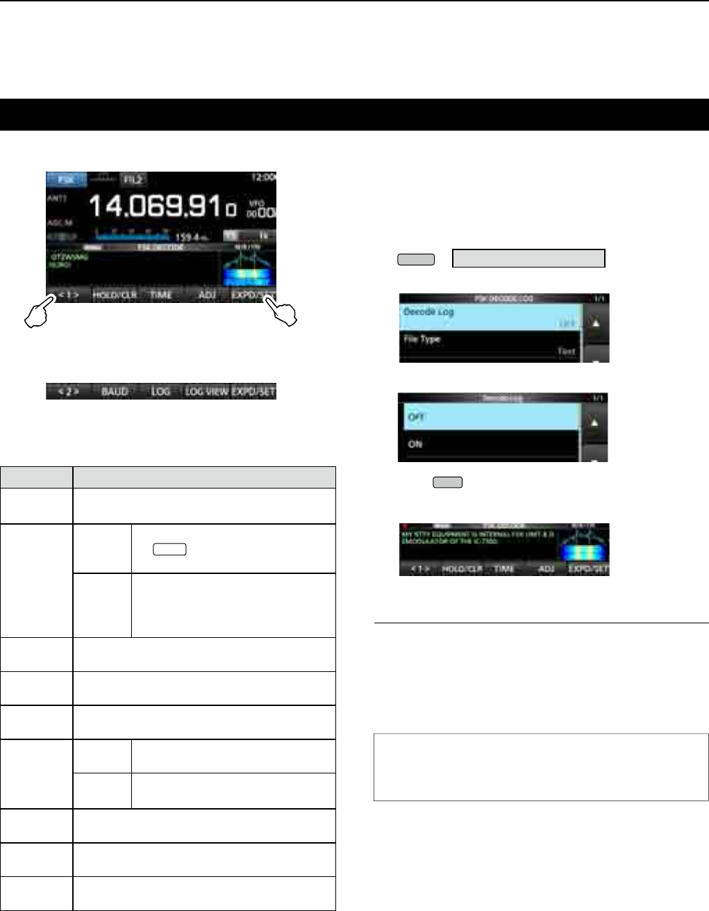
5OTHER FUNCTIONS
5-6
Touch for 1 second to open the FSK
DECODE SET screen (p. 5-8)
FSK DECODE screen
FUNCTION MENU2
[Function Menu Items]
Key Action
<1>
<2>
Toggles the Function menu between Menu 1
and Menu 2.
HOLD/CLR
Touch
Turns the Hold function ON or OFF.
L “ HOLD ” is displayed, and the
FSK DECODE screen stops.
Touch for
1 second
Clears the displayed characters.
L While the Hold function is ON,
this clears the characters and
cancels the Hold function.
TIME Touch to insert a time stamp into the decoded
contents.
ADJ Touch to open the THRESHOLD screen to set
the threshold level.
DEF Touch for 1 second to reset to the default
threshold level.
EXPD/SET
Touch Selects the Expanded or Normal
screen.
Touch for
1 second
Opens the FSK DECODE SET
screen.
BAUD Touch to toggle the FSK decoding baud rate
between 45 bps and 50 bps.
LOG Opens the FSK DECODE LOG screen.
L Starts/Stops logging or selects the le type.
LOG VIEW Opens the FSK DECODE LOG VIEW screen.
LYou can check the saved log les.
zTouch <1> to switch to Menu 2.
Receiving FSK (RTTY) signal (Continued)
DTurning ON the FSK log
Turn ON the FSK log to save the received FSK signal
records onto an SD card (user supplied).
LInsert an SD card before attempting to save logs.
1.
Open the FSK DECODE LOG screen in the FSK mode.
MENU
» DECODE > <1> > LOG
2. Select “Decode Log.”
3. Select “ON.”
4. Push
EXIT
.
• “●” is displayed on the FSK DECODE screen when the
Decode Log item is set to "ON."
5. To turn OFF the FSK log, select “OFF” in step 3.
TIP: How to reset to the default setting
Touching the item or its option for 1 second displays the
Quick menu, and then touch “Default” to reset to the
default setting.
InformationL:
In step 2 in the above procedure, you can select the
le type to save a log onto an SD card from Text and
HTML (default: Text).
L You cannot change the le type while logging.
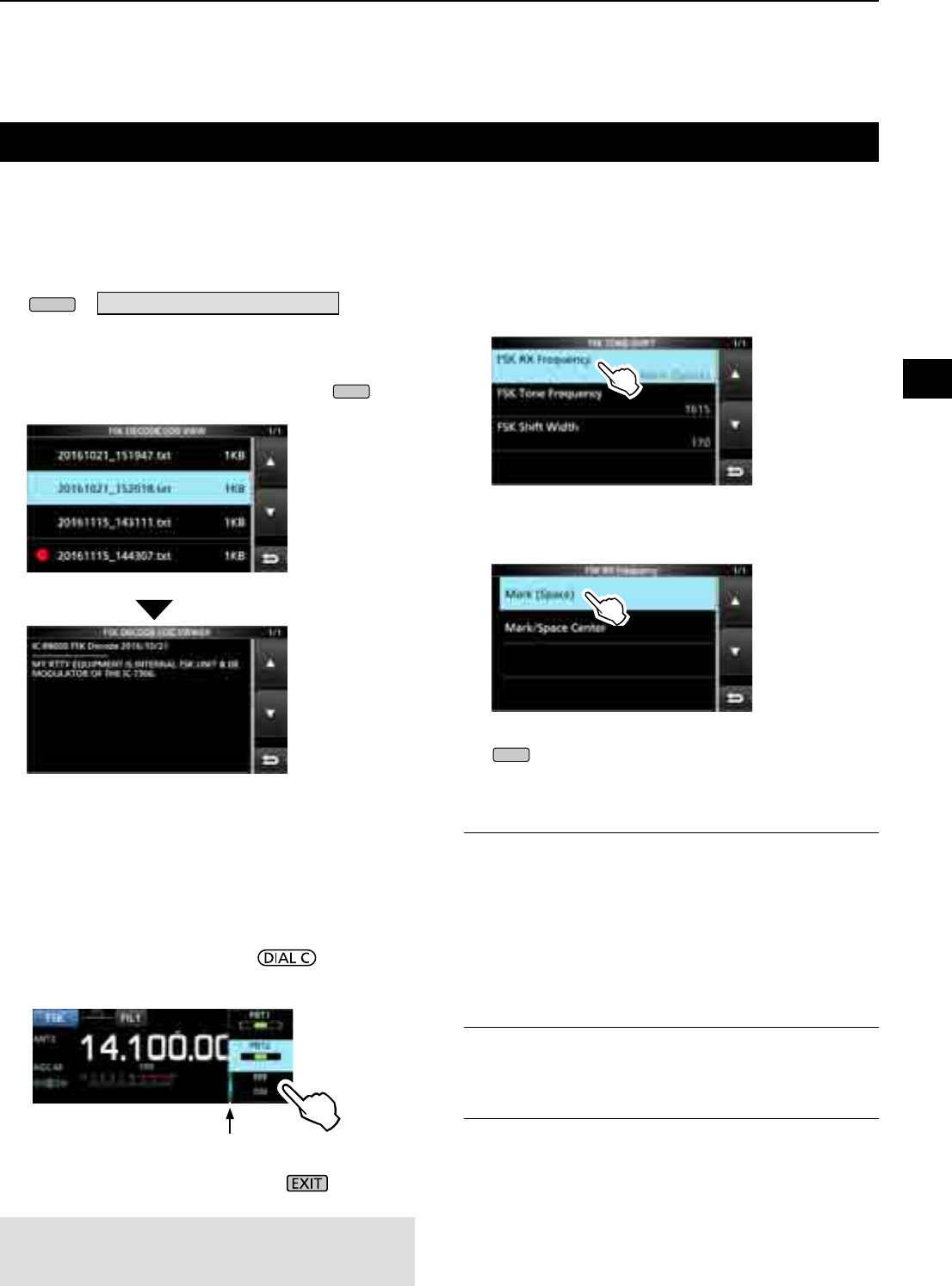
5
OTHER FUNCTIONS
1
2
3
4
5
6
7
8
9
10
11
12
13
14
15
16
17
18
19
20
21
5-7
Receiving FSK (RTTY) signal (Continued)
DViewing the FSK log contents
You can check the FSK log contents saved on an SD card.
1. Open the FSK DECODE LOG VIEW screen in the
FSK mode.
MENU
» DECODE > <1> > LOG VIEW
2. Select the desired log file to view.
L The le with “●” is currently logging. You cannot check
the log contents.
L To close the FSK DECODE screen, push
EXIT
several times.
FSK DECODE LOG VIEW screen
Example of a log saved in the text format.
DTwin Peak Filter
The Twin Peak Filter (TPF) changes the audio
frequency response by boosting the mark and space
frequencies for better reception of FSK signals.
1. While in the FSK mode, push .
2. Touch [TPF].
• Each touch turns the function ON or OFF.
3. To close the MENU screen, push .
Lights while the TPF is ON
NOTE: When you are using the Twin Peak Filter, the
received audio output may increase. This is not a
malfunction.
DFSK tone and shift setting
You can change the FSK RX frequency, tone and shift
frequencies, on the [FSK TONE/SHIFT] screen.
1. Touch [TONE/SHIFT] on the function screen.
2. Touch the desired item.
(Example: FSK RX frequency)
3. Select the desired option.
(Example: Mark (Space))
4. To close the FSK TONE/SHIFT screen, push
EXIT
several times.
FSK RX Frequency (Default: Mark/Space Center)
Selects the FSK RX frequency.
• Mark (Space):
Displays the higher frequency in the Mark or Space
frequency.
• Mark/Space Center:
Displays the center frequency between the Mark
and Space frequency.
FSK Tone Frequency (Default: 1615)
Selects the FSK mark frequency.
• Options: 1275, 1500, 1615 or 2125 (Hz)
FSK Shift Width (Default: 170)
Selects the FSK shift width between the Mark and
Space frequencies.
• Options: 170, 200, 425, 800 or 850 (Hz)
The FSK TONE/SHIFT screen
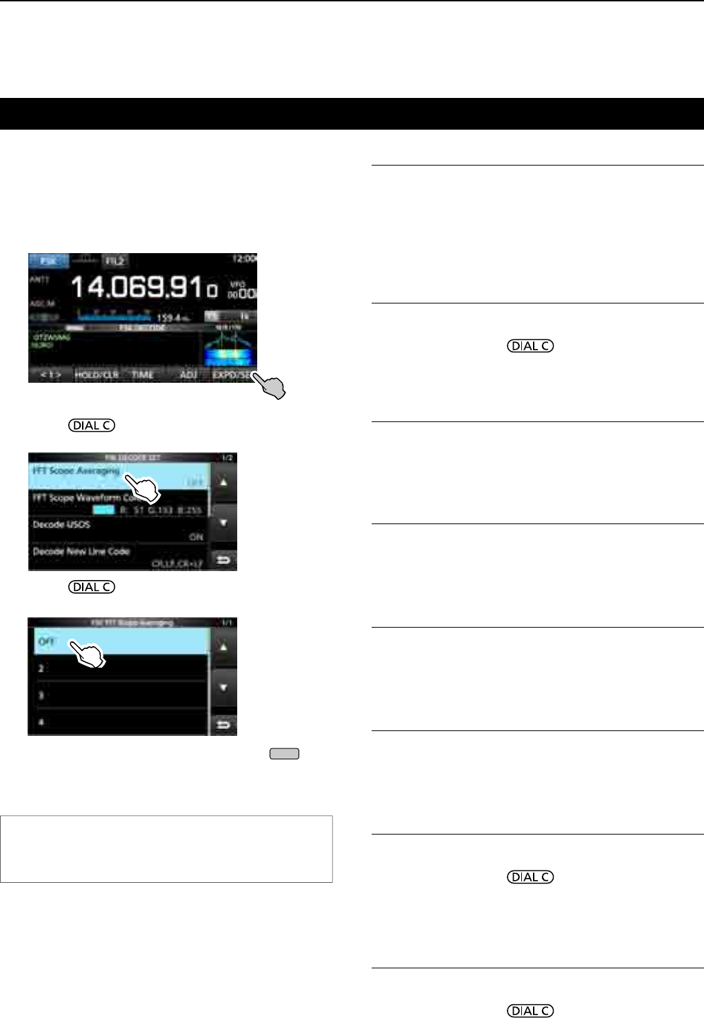
5OTHER FUNCTIONS
5-8
Receiving FSK (RTTY) signal (Continued)
DAbout the FSK DECODE SET screen
You can change the settings related to FSK signal
decoding.
1. Touch [DECODE] on the MENU screen.
2. Touch [EXPD/SET] for 1 second.
3. Rotate and touch the desired item.
(Example: FFT Scope Averaging)
4. Rotate and touch the desired option.
(Example: 2)
5. To close the FSK DECODE screen, push
EXIT
several times.
FFT Scope Averaging (Default: OFF)
Set the FFT scope waveform averaging function
(noise reduction by averaging the waveform) to
between 2 and 4 or to OFF.
L Set the default or smaller number for tuning on FFT scope
waveform.
FFT Scope Waveform Color
(Default: R: 51, G: 153, B: 255)
Set the color of the FFT scope waveform.
L Touch and select the R (Red), G (Green) or B (Blue)
scale, and then rotate to adjust the ratio to
between 0 and 255.
LThe color is displayed in the box above the RGB scale.
Decode USOS (Default: ON)
Turn the Letter Code Decoding function ON or OFF.
• ON: Decodes as a letter code after receiving a “space.”
• OFF: Decodes as a character code.
L USOS stands for UnShift On Space function.
Decode New Line Code (Default: CR, LF, CR+LF)
Select the FSK decoder new line code.
• CR,LF,CR+LF: Makes a new line with any codes.
• CR+LF: Makes a new line with only CR+LF code.
L
CR stands for Carriage Return, and LF stands for Line Feed.
Time Stamp (Time) (Default: Local)
Select the local time or UTC time to store on the FSK
receive log.
• Local: In local time
• UTC: In UTC time
Time Stamp (Frequency) (Default: ON)
Select whether or not to store the frequency data on
the FSK receive log.
• OFF: Does not store
• ON: Stores the frequency data
Font Color (Receive)
(Default: R: 128, G: 255, B: 128)
Set the text font color for received characters.
L Touch and select the R (Red), G (Green) or B (Blue)
scale, and then rotate to adjust the ratio to
between 0 and 255.
LThe color is displayed in the box above the RGB scale.
Font Color (Time Stamp)
(Default: R: 0, G: 155, B: 189)
Set the text font color for Time Stamp characters.
L Touch and select the R (Red), G (Green) or B (Blue)
scale, and then rotate to adjust the ratio to
between 0 and 255.
LThe color is displayed in the box above the RGB scale.
TIP: How to reset to the default setting
Touching the item or its option for 1 second displays the
Quick menu, and then touch “Default” to reset to the
default setting.
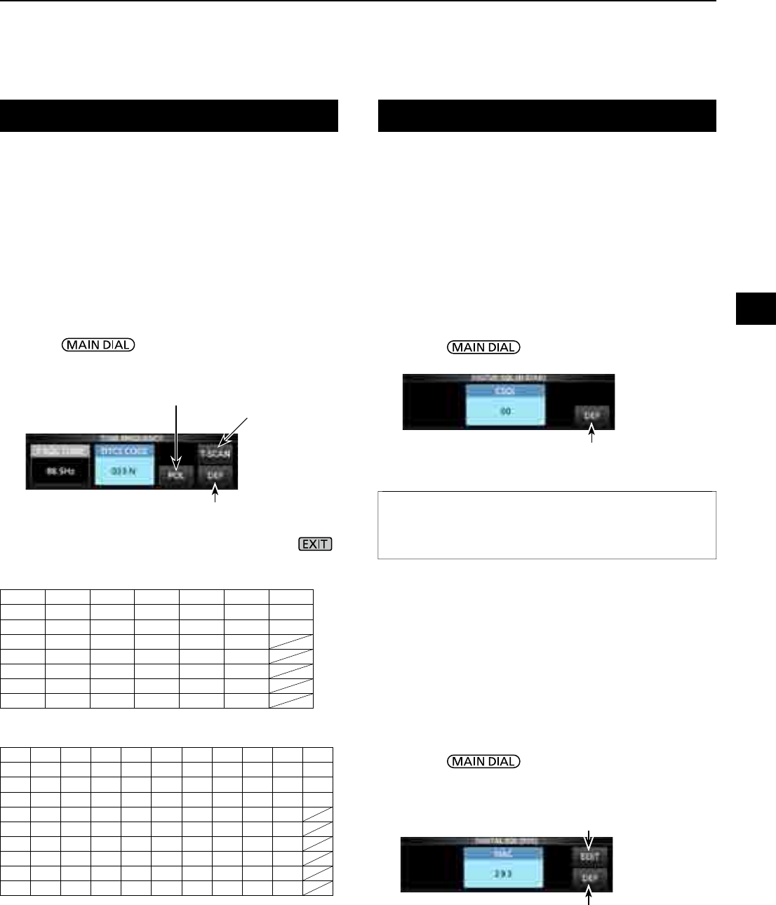
5
OTHER FUNCTIONS
1
2
3
4
5
6
7
8
9
10
11
12
13
14
15
16
17
18
19
20
21
5-9
Tone squelch function
D.SQL (Digital Squelch) function
FM mode
The Tone squelch opens only when you receive a
signal that includes a matching subaudible tone.
LRefer to page 9-11 for Tone scan or Code scan.
1. Touch [TONE] on the FUNCTION screen.
•
Each touch changes between [TSQL], [DTCS] and [OFF].
2. To change the Tone frequency or DTCS code,
touch [TONE] for 1 second.
• Opens the TONE FREQUENCY screen.
3. Touch [T-SQL TONE] or [DTCS CODE], then
rotate , to change the frequency or code.
• Touch [POL] to toggle the DTCS polarity.
• The settings are stored in each memory channel.
4.
To close the TONE FREQUENCY screen, push .
DDigital Code Squelch
D-STAR mode
The squelch opens only when you receive a D-STAR
signal that includes a matching CSQL (Code Squelch).
• Settable range: 00 ~ 99
1. Touch [D.SQL] on the FUNCTION screen.
• Each touch turns the function ON or OFF.
2. To change the digital code, touch [D.SQL] for
1 second.
• Opens the DIGITAL SQL (D-STAR) screen.
3. Rotate to set the code.
L The setting is stored in each memory channel.
DNetwork Access Code (NAC)
P25 mode
The squelch opens only when you receive an APCO
P25 signal that includes a matching NAC.
• Settable range: 000 ~ FFF (in hexadecimal)
1. Touch [D.SQL] on the FUNCTION screen.
• Each touch turns the function ON or OFF.
2. To change the NAC, touch [D.SQL] for 1 second.
• Opens the DIGITAL SQL (P25) screen.
3. Rotate to set the code.
• Touch [EDIT] to enter using the keypad.
L The setting is stored in each memory channel.
InformationL
When receiving the data communication signal, the data is
restored, regardless of the digital code setting.
•Selectable tone frequencies (Hz)
67.0 88.5 114.8 151.4 177.3 203.5 250.3
69.3 91.5 118.8 156.7 179.9 206.5 254.1
71.9 94.8 123.0 159.8 183.5 210.7 150.0
74.4 97.4 127.3 162.2 186.2 218.1
77.0 100.0 131.8 165.5 189.9 225.7
79.7 103.5 136.5 167.9 192.8 229.1
82.5 107.2 141.3 171.3 196.6 233.6
85.4 110.9 146.2 173.8 199.5 241.8
•Selectable DTCS codes
023 054 125 165 245 274 356 445 506 627 732
025 065 131 172 246 306 364 446 516 631 734
026 071 132 174 251 311 365 452 523 632 743
031 072 134 205 252 315 371 454 526 654 754
032 073 143 212 255 325 411 455 532 662
036 074 145 223 261 331 412 462 546 664
043 114 152 225 263 332 413 464 565 703
047 115 155 226 265 343 423 465 606 712
051 116 156 243 266 346 431 466 612 723
053 122 162 244 271 351 432 503 624 731
Touch for 1 second to reset
to the default setting.
Toggles the polarity (DTCS) Starts or stops a Tone
scan (p. 9-11)
Resets to the default setting.
Enter using the keypad
Touch for 1 second to reset
to the default setting.
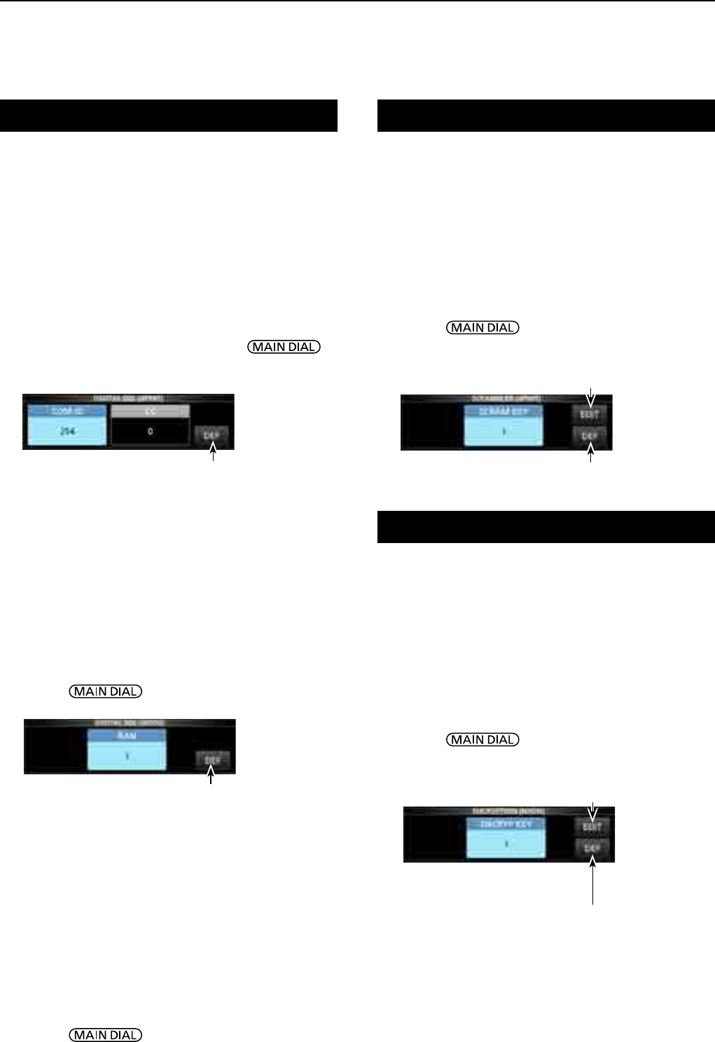
5OTHER FUNCTIONS
5-10
Descrambler function
Decryption function
dPMR mode
You can descramble the scrambled dPMR (Tire2)
communication by entering the appropriate key.
• Settable range: 1 ~ 32767
1. Touch [SCRAM] on the FUNCTION screen.
• Each touch turns the function ON or OFF.
2. To change the descramble key, touch [SCRAM]
for 1 second.
• Opens the SCRAMBLER (dPMR) screen.
3. Rotate to set the key.
• Touch [EDIT] to enter using the keypad.
L The setting is stored in each memory channel.
NXDN-vn, NXDN-n and DCR modes
You can decrypt the encrypted NXDN or DCR
communication by entering the appropriate key.
• Settable range: 1 ~ 32767
1. Touch [ENCRYP] on the FUNCTION screen.
• Each touch turns the function ON or OFF.
2. To change the decrypting key, touch [ENCRYP]
for 1 second.
• Opens the ENCRYPTION screen.
3. Rotate to set the key.
• Touch [EDIT] to enter using the keypad.
L The setting is stored in each memory channel.
D Group Code (COM ID) and CC
dPMR mode
The squelch opens only when you receive a dPMR signal
that includes a matching COM ID (Common ID) or CC.
• Settable range: 1 ~ 255 (COM ID), 0 ~ 63 (CC)
1. Touch [D.SQL] on the FUNCTION screen.
• Each touch changes between [COM ID], [CC] or [OFF].
2. To change the COM ID or CC, touch [D.SQL] for
1 second.
• Opens the DIGITAL SQL (dPMR) screen.
3. Touch [COM ID] or [CC] then rotate to
set the ID or code.
L The settings are stored in each memory channel.
DRadio Access Number (RAN)
NXDN-vn and NXDN-n modes
The squelch opens only when you receive a NXDN
signal that includes a matching RAN.
• Settable range: 0 ~ 63
1. Touch [D.SQL] on the FUNCTION screen.
• Each touch turns the function ON or OFF.
2. To change the number, touch [D.SQL] for 1 second.
• Opens the DIGITAL SQL (NXDN) screen.
3. Rotate to set RAN.
L The setting is stored in each memory channel.
D.SQL (Digital Squelch) (Continued)
Touch for 1 second to reset
to the default setting.
Touch for 1 second to reset
to the default setting.
Resets to the default setting.
Enter using the keypad
Resets to the default setting.
Enter using the keypad
ENCRYPTION KEY screen
(Example: NXDN)
DUser Code (UC)
DCR mode
The squelch opens only when you receive a DCR
signal that includes a matching UC.
• Settable range: 1 ~ 511
1. Touch [D.SQL] on the FUNCTION screen.
• Each touch turns the function ON or OFF.
2. To change the number, touch [D.SQL] for
1 second.
• Opens the DIGITAL SQL (DCR) screen.
3. Rotate to set UC.
L The setting is stored in each memory channel.
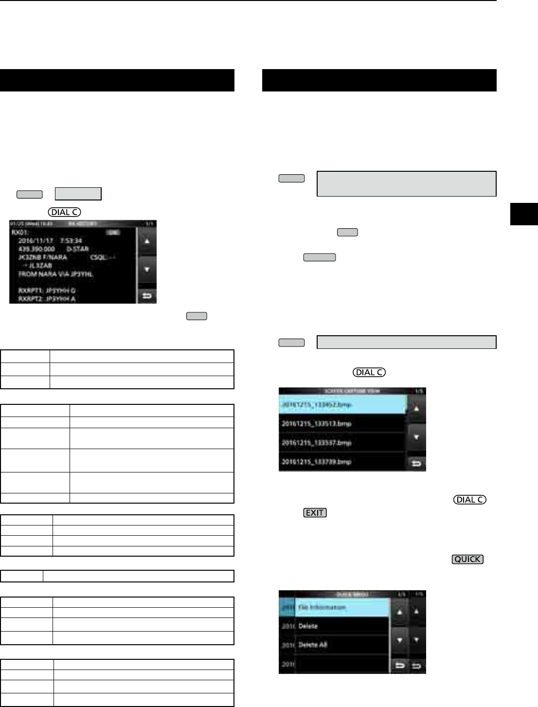
5
OTHER FUNCTIONS
1
2
3
4
5
6
7
8
9
10
11
12
13
14
15
16
17
18
19
20
21
5-11
Receive history log
DIGITAL mode
When a digital is received, the call signs, IDs and so on are
stored in the RX history. Up to 50 log entries can be stored.
•
When you receive the 51th call, the oldest history will be deleted.
• Even if the receiver is turned OFF, the RX record will not be deleted.
1. Touch [HISTORY] on the MENU screen.
MENU
» HISTORY
2. Rotate then touch a log to view.
3. To close the RX HISTORY screen, push
EXIT
.
•Common
[RX history items]
•D-STAR
•P25 (Phase 1)
•dPMR (Tier2)
•NXDN-vn, NXDN-n and DCR
•dPMR (Tier1)
Frequency Frequency
Mode Signal mode
Time
Date and time the call was received.
Caller call sign The call sign of the caller station.
Called call sign The call sign of the called station.
Message Any message included in the received
call, if programmed.
RXRPT1
(FROM repeater)
The call sign of the repeater that was
accessed by the caller station.
RXRPT2
(TO repeater)
The call sign of the repeater you received
the call from.
CSQL Digital squelch code.
Caller ID The ID of the caller station.
Called ID The ID of the called station.
NAC Network Access Code
Type of call ALL (All), GRP (Group) or IND (Individual)
Caller ID The ID of the caller station.
Called ID The ID of the called station.
CC –
Type of call
All (Displayed only if the signal is an All call.)
Caller ID The ID of the caller station.
Called ID The ID of the called station.
RAN/UC* Radio Access Number/User Code*
Type of call ALL (All), GRP (Group) or IND (Individual)
COM ID –
You can capture the receiver screen onto an SD card.
LSome displays cannot be captured.
DCapturing a screen
1. Open the “Screen Capture [POWER] Switch” screen.
MENU
» SET > Function >
Screen Capture [POWER] Switch
2. Touch “ON.”
3. To close the Screen Capture [POWER] Switch
screen, push
EXIT
several times.
4. Arrange the screen you want to capture.
5. Push
POWER
to capture the screen.
• The captured screen is saved onto the SD card.
• If there is
L You can change the picture le format. (p. 11-4)
DViewing the captured screen
1. Open the SCREEN CAPTURE VIEW screen.
MENU
» SET > SD Card > Screen Capture View
• The capture list is displayed.
2. Rotate and push to select and open the
desired screen capture.
• The selected screen capture is displayed.
L While a screen capture is displayed, you can scroll
through all the screen captures by rotating .
3. Push to close and return to the SCREEN
CAPTURE VIEW screen.
Other options in the capture list
1. While the capture list is displayed, push to
open the QUICK MENU.
2. Select the desired option.
• File Information: Displays the name, size, and date of
the selected screen capture.
• Delete:
On the conrmation dialog, select [YES] to delete.
• Delete All: On the conrmation dialog, select [YES] to
delete all.
Screen Capture function
(Example: D-STAR)
*For DCR.
L If the received is not an Individual call or the DCR
transceiver manufacture is not Icom, only User Code is
displayed.
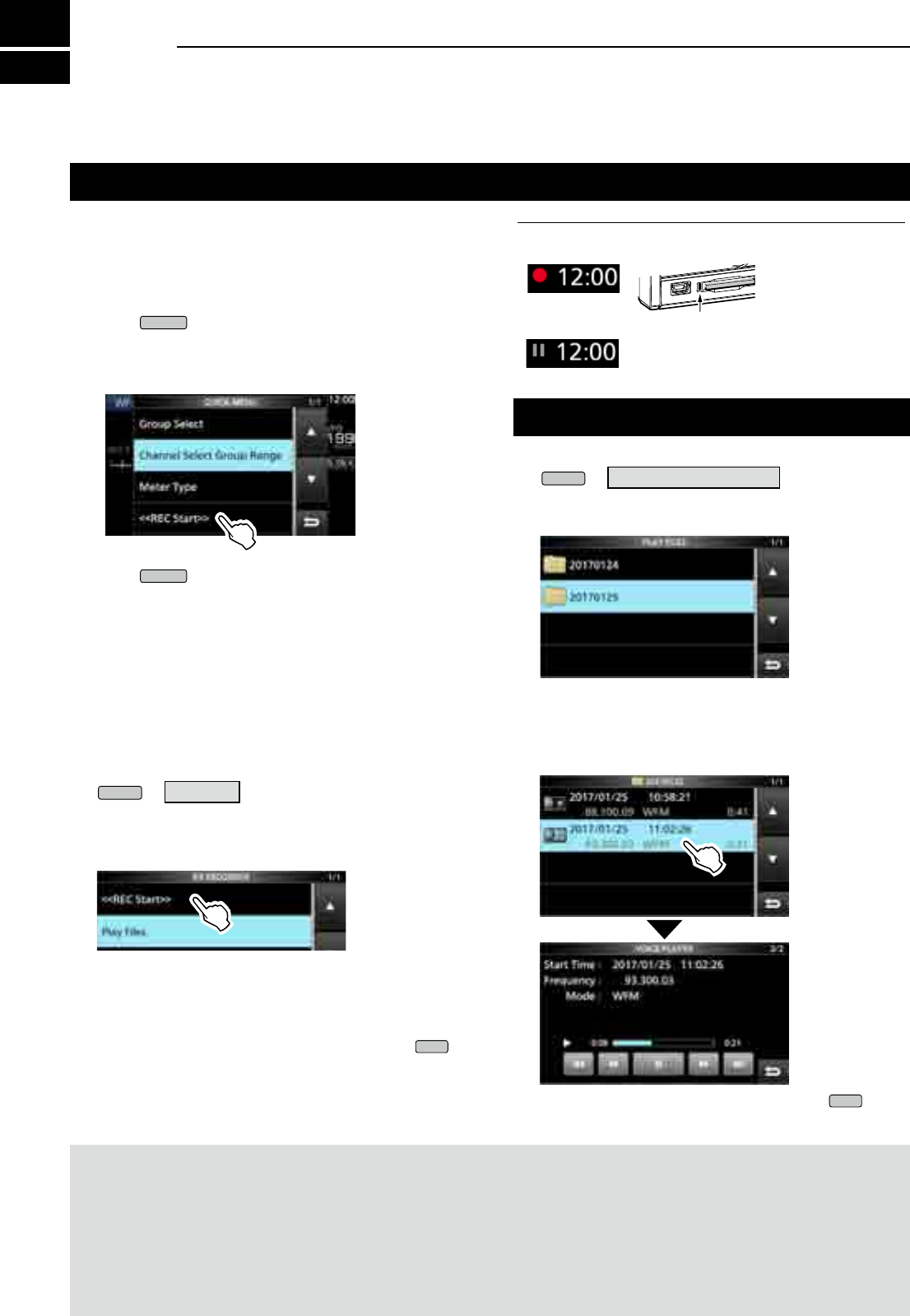
6RECORDING AND PLAYING BACK
6-16-1
Recording
You can record the received audio onto an SD card.
DQuick recording
You can quickly start to record the receive audio.
1. Push
QUICK
.
2. Touch [<<REC Start>>].
• Startsrecordingand“Recordingstarted.”isbriey
displayed and the SD card LED starts to blink.
3. Push
QUICK
again.
4. Touch “<<REC Stop>>.”
• Stopsrecordingand“Recordingstopped.”isbriey
displayed.
DNormal recording
Youcanstarttorecordafteryoucongurethe
recording settings.
1. Open the RECORD screen.
MENU
» RECORD
2. If you want to change the recorder setting, touch
[Recorder Set]. (p. 6-4)
3. Touch “<<REC Start>>.”
• Recording starts.
4. Touch “<<REC Stop>>.”
• Stopsrecordingand“Recordingstopped.”isbriey
displayed.
5. To close the RX RECORDER screen, push
EXIT
.
NOTE:
• An SD card (user supplied) is required.
• As the default setting, the recording is paused while the squelch is closed, and resumes when a signal is received. You can
continue recording regardless of the signal presence. (p. 6-4)
• If your SD card does not have an "IC-R8600" folder, back up any data on the SD card, insert it in the receiver's card slot and
then format it using the built-in format function. See “Formatting an SD card” (p. 7-2) for details.
• Once the recording starts, it continues, even if the receiver is turned OFF and ON again.
• The recording continues until you touch <<REC Stop>> or the free space on the SD card has run out.
• Whentherecordingle’scontentbecomes2GB,thereceivercontinuestorecord,buttoanewle.
InformationL: Record indication
• While recording:
• While the recording is paused:
SD
Playing back
1. Open the PLAY FILES screen.
MENU
» RECORD > Play Files
2. Select a folder that contains the file you want to
playback.
• Thelelistisdisplayed.
3. Select the desired file.
• Starts a playback.
LPlaybackcontinuestothenextle,andstopswhen
thelastleinthefolderisplayedback.
4. To close the PLAY FILES screen, push
EXIT
several times.
Blinksinblue
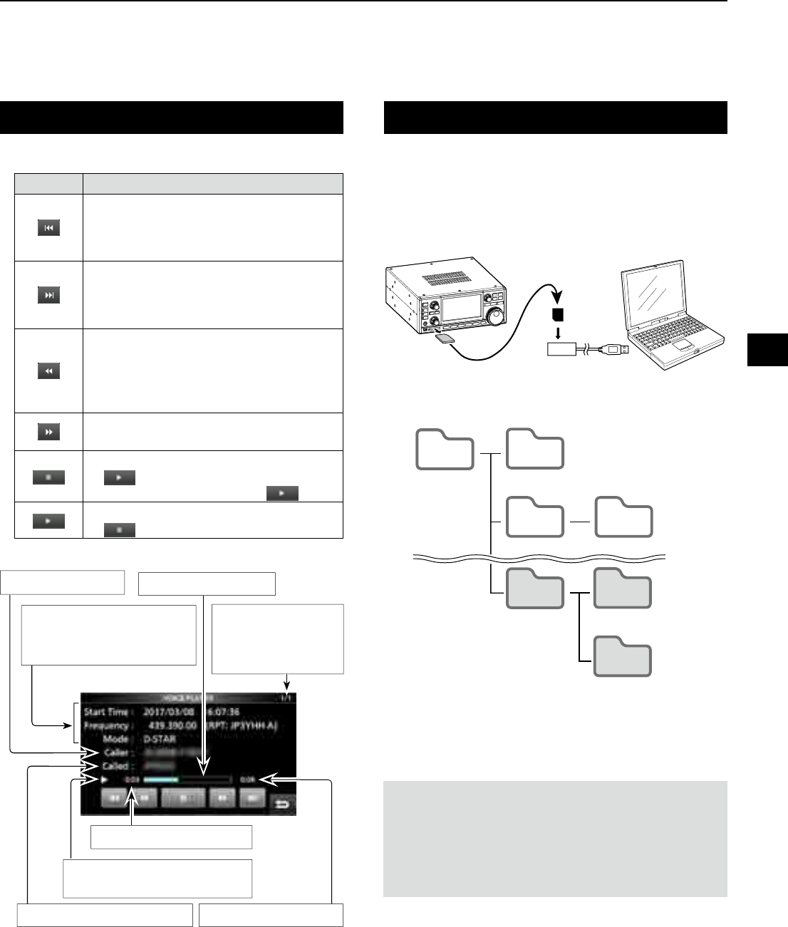
6
RECORDING AND PLAYING BACK
1
2
3
4
5
6
7
8
9
10
11
12
13
14
15
16
17
18
19
20
21
6-2
Operation while playing back
The number of le
Beingplayedback,
and the total number
ofrecordedles.
Playback elapsed time
Called station's call sign
Caller's call sign Playback process
Playback icon
LNot displayed while paused.
Total recorded time
Key Operation
Touchtoplaythepreviousle.
LI f thereareotherlesinthefolder,whilethe
oldestleisplayingback,touchthiskeyto
startplayingthebeginningofthele.
Touchtoplaythenextle.
LI f thereareotherlesinthefolder,while
themostrecentleisplayingback,touch
this key to stop the playback.
Touch to rewind to the skip time point.
(Default: 10 seconds)
LI f youtouchthiskeywithintherst
1secondofthele,theendofthe
previouslyrecordedlewillplayback.
Touch to fast forward to the skip time
point. (Default: 10 seconds)
Touch to pause while playing.
L is displayed while pausing.
LTo cancel the pausing, touch .
Touchtoplaybackthele.
L is displayed while pausing.
Operations on the Playback screen.
Playing back on a PC
You can also playback on a PC.
L The recorded information (frequency, date, and so on) is
not displayed.
1. Insert the SD card into your PC's SD card slot.
NOTE:
• The operations while playing back may differ, depending
ontheapplication.Refertotheapplication’sinstruction
manual for details.
• Whentheledoesnotplayback,evenifyoudoubleclick
thele,downloadanappropriatesoftwareapplication.
(Example: Windows Media® Player)
3. Double-click the folder where the file you want to
playback is saved.
4. Double-click the file to playback.
2. Double-click the “Voice” folder.
IC-R8600 PC
Memory Card reader
SD card
IC-R8600 Capture
Decode Fsk
yyyymmdd
yyyymmdd
RxLog
Setting
Voice
IC-R8600 Capture
Decode Fsk
yyyymmdd
yyyymmdd
RxLog
Setting
Voice
Recording Information
Recording start time, receive
frequency and mode.
Hierarchy1 Hierarchy2 Hierarchy3
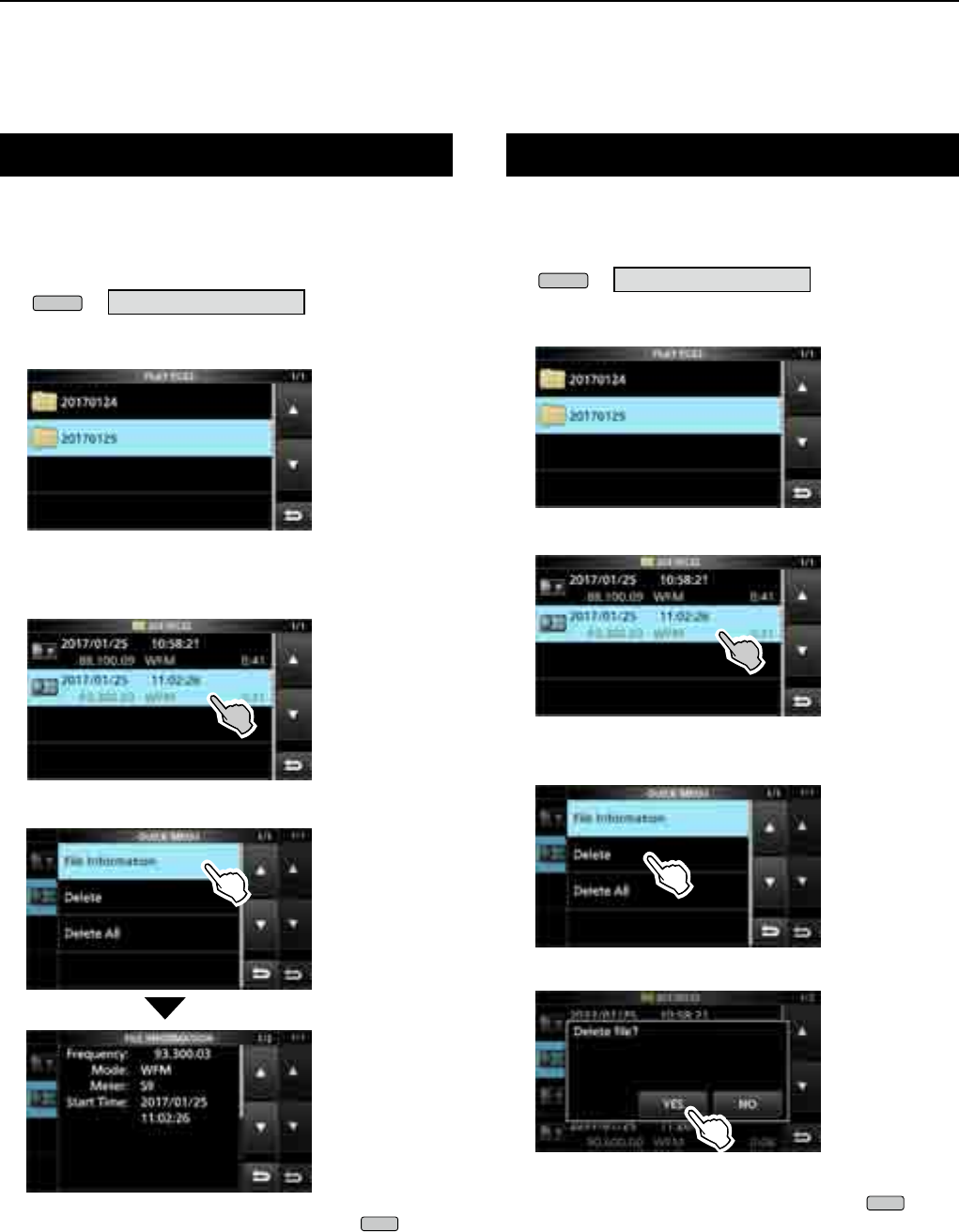
6RECORDING AND PLAYING BACK
6-3
Checking the le information
TheIC-R8600candisplaytherecordedle’s
operating frequency, operating mode, date, and so on.
1. Open the PLAY FILES screen.
MENU
» RECORD > Play Files
2. Select a folder that contains the file you want to
check.
• Thelelistisdisplayed.
L Touch a folder for 1 second to check the folder
information.
3. Touch the file you want to check for 1 second.
• The QUICK MENU screen opens.
4. Touch “File Information.”
5. To close the PLAY FILES screen, push
EXIT
several times.
Deleting a le
Youcandeletetherecordedaudiole.
1. Open the PLAY FILES screen.
MENU
» RECORD > Play Files
2. Select a folder that contains the file you want to
delete.
• Thelelistisdisplayed.
3. Touch the desired file to delete for 1 second.
• The QUICK MENU screen opens.
4. Touch “Delete.”
• Touch"DeleteAll"todeletealllesinthefolder.
5. Touch [YES] on the confirmation dialogue.
• Theselectedleisdeleted.
6. To close the PLAY FILES screen, push
EXIT
several times.
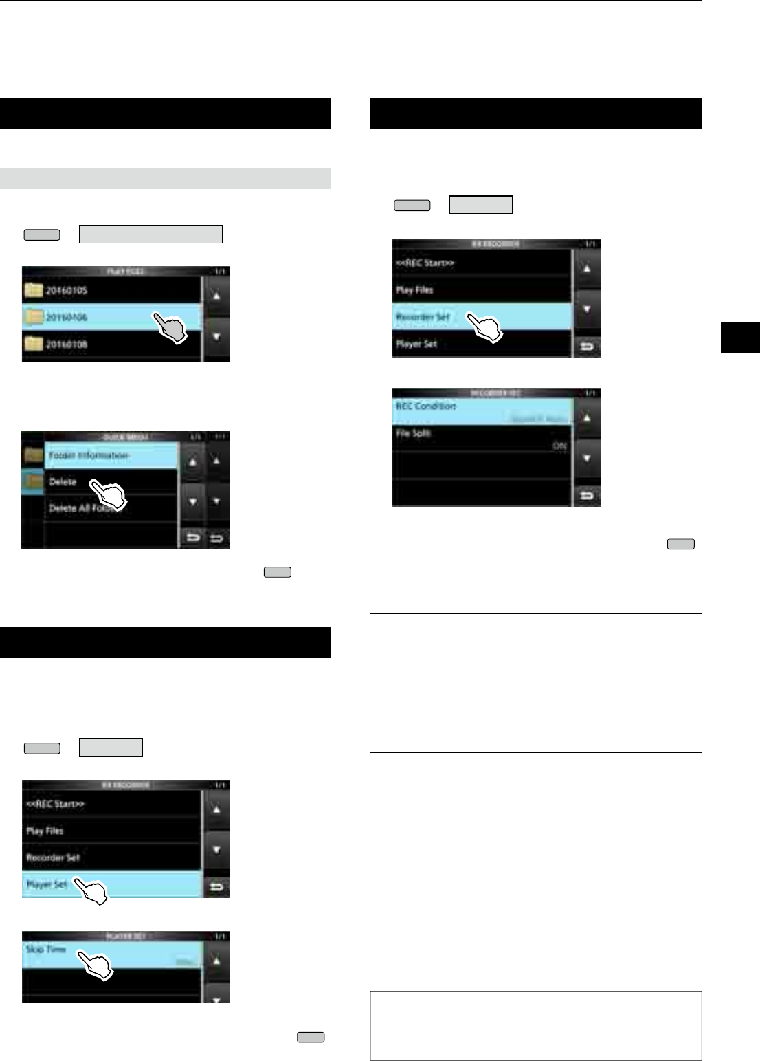
6
RECORDING AND PLAYING BACK
1
2
3
4
5
6
7
8
9
10
11
12
13
14
15
16
17
18
19
20
21
6-4
Deleting a folder
1. Open the PLAY FILES screen.
MENU
» RECORD > Play Files
2. Touch the folder to delete for 1 second.
3. Touch “Delete.”
•
Touch “Delete All Folders” to delete all folders at one time.
4. Touch [YES] on the confirmation dialogue.
• The selected folder is deleted.
5. To close the PLAY FILES screen, push
EXIT
several times.
You can delete the recorded audio folder.
NOTE:Allthelesinthefolderarealsodeleted.
RECORDER SET screen
You can change the RECORDER SET settings.
1. Open the RX RECORDER screen.
MENU
» RECORD
2. Select “Recorder Set.”
3. Select an item.
4. Select the desired option or value.
5. To close the RECORDER SET screen, push
EXIT
several times.
REC Condition (Default: Squelch Auto)
Select the recording condition for receive.
• Always: Records even if no signal is received.
• Squelch Auto: Records only when the squelch
opens.
( The recording will be paused when
the squelch closes while recording.)
File Split (Default: ON)
Turn the File Split function ON or OFF.
• OFF: Theaudioiscontinuouslyrecordedintothele
even if the squelch status changes between
open and closed.
Whentherecordingle’ssizebecomes
2GB,theIC-R8600continuestorecord,butto
anewle.
• ON: While recording, and if the squelch status
changesbetweenopenandclosed,anewle
is automatically created in the same folder,
and the audio is saved into the new one.
TIP: How to reset to the default setting
Touching the item or its option for 1 second displays
the Quick menu, and then touch “Default” to reset to
the default setting.
PLAYER SET screen
You can change the fast forward or rewind skip time in
the PLAYER SET screen.
1. Open the RX RECORDER screen.
MENU
» RECORD
2. Select “Player Set.”
3. Touch “Skip Time.”
4. Select an option.
5. To close the RECORDER SET screen, push
EXIT
several times.
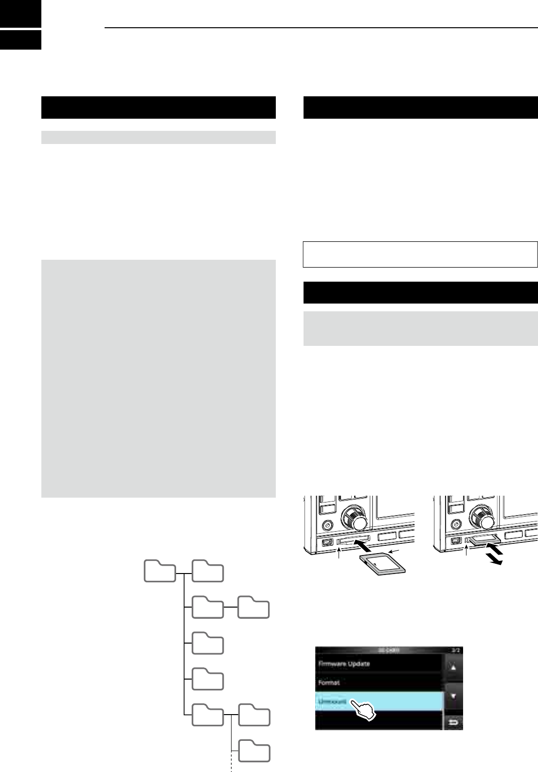
7USING AN SD CARD
7-17-1
About the SD card Saving data onto the SD card
The SD and SDHC cards are not supplied by Icom. User supplied.
You can use an SD card of up to 2 GB, or an SDHC of
up to 32 GB. Icom has checked the compatibility with the
following SD and SDHC cards.
(As of March 2017)
• Brand: SanDisk®
• Type: SD (2 GB) and SDHC (4, 8, 16 and 32 GB)
L The above list does not guarantee the card’s performance.
L Throughout the rest of this document, the SD card and an
SDHC card are simply called the SD card or the card. TIP: Icom recommends that you save the receiver’s
factory default data for backup.
NOTE: Format all SD cards to be used with the
receiver with the built-in Format function. Format, even
preformatted cards for PCs or other uses. (p. 7-2)
NOTE:
•
Before using the SD card, thoroughly read the card’s instructions.
• If you do any of the following, the card data may be
corrupted or deleted.
- You remove the card from the receiver while the card
is being accessed.
- A power failure occurs or the power cable is
disconnected while the card is being accessed.
- You drop, impact or vibrate the card.
• Do not touch the contacts of the card.
• The receiver takes a longer time to recognize a large
capacity card.
• The card will get warm if continuously used for a long
period of time.
• The card has a certain lifetime, so data reading or writing
may not be possible after using it for a long period.
When reading or writing data is impossible, the card’s
lifetime has ended. In that case, use a new one.
We recommend you make a separate backup le of the
important data onto your PC.
• Icom will not be responsible for any damage caused by
data corruption of a card.
You can save the following data onto the card:
• Data settings of the receiver
Memory channel contents saved in the receiver.
• Communication contents
The recorded audio.
• Communication log
The receive history log.
• FSK (RTTY) decode log
The received FSK decode history log.
• Captured screens
Inserting or removing the SD card
DInserting
Insert the card into the slot until it locks in place, and
makes a ‘click’ sound.
• Displays the SD card icon when the SD card is inserted.
LBe sure of the card orientation.
DRemoving (While the receiver is OFF)
Push in the SD card until a click sounds.
• The card is unlocked, and you can pull it out.
L If you remove the SD card while the receiver’s power is
ON, be sure to unmount it.
Inserting Removing
Lights blue Turns OFF 1. Push
2. Pull
Cutout
LOCK
SD
LOCK
SD
DRemoving (While the receiver is ON)
Proceed the unmount as shown below, otherwise the
data may be corrupted or deleted.
1. Open the SD CARD screen.
2. Touch [Unmount].
• Unmount conrmation dialogue appears.
3. Touch [YES].
• "Unmount is completed." is displayed.
4. Push the SD card, then pull it out.
DSD card’s folder contents
The following folders are created in the SD card.
q
All folders are
contained in this folder.
w The captured screen
data (‘.png’ or ‘.bmp’).
e The FSK decode log
folder is created.
r
The received FSK
decode log data (‘.txt’
or ‘.html’).
t The receive history
log data (‘.csv’).
y The receiver’s setting
data (‘.icf’).
u The recorded audio
data folders are created.
i Recorded audio les
(‘.wav’).
IC-R8600
q w
e r
t
y
u i
i
Capture
Decode Fsk
yyyymmdd
yyyymmdd
RxLog
Setting
Voice
The folder name is automatically
created in the following format:
yyyymmdd
(yyyy:Year, mm:month, dd:day)
Hierarchy1 Hierarchy2 Hierarchy3
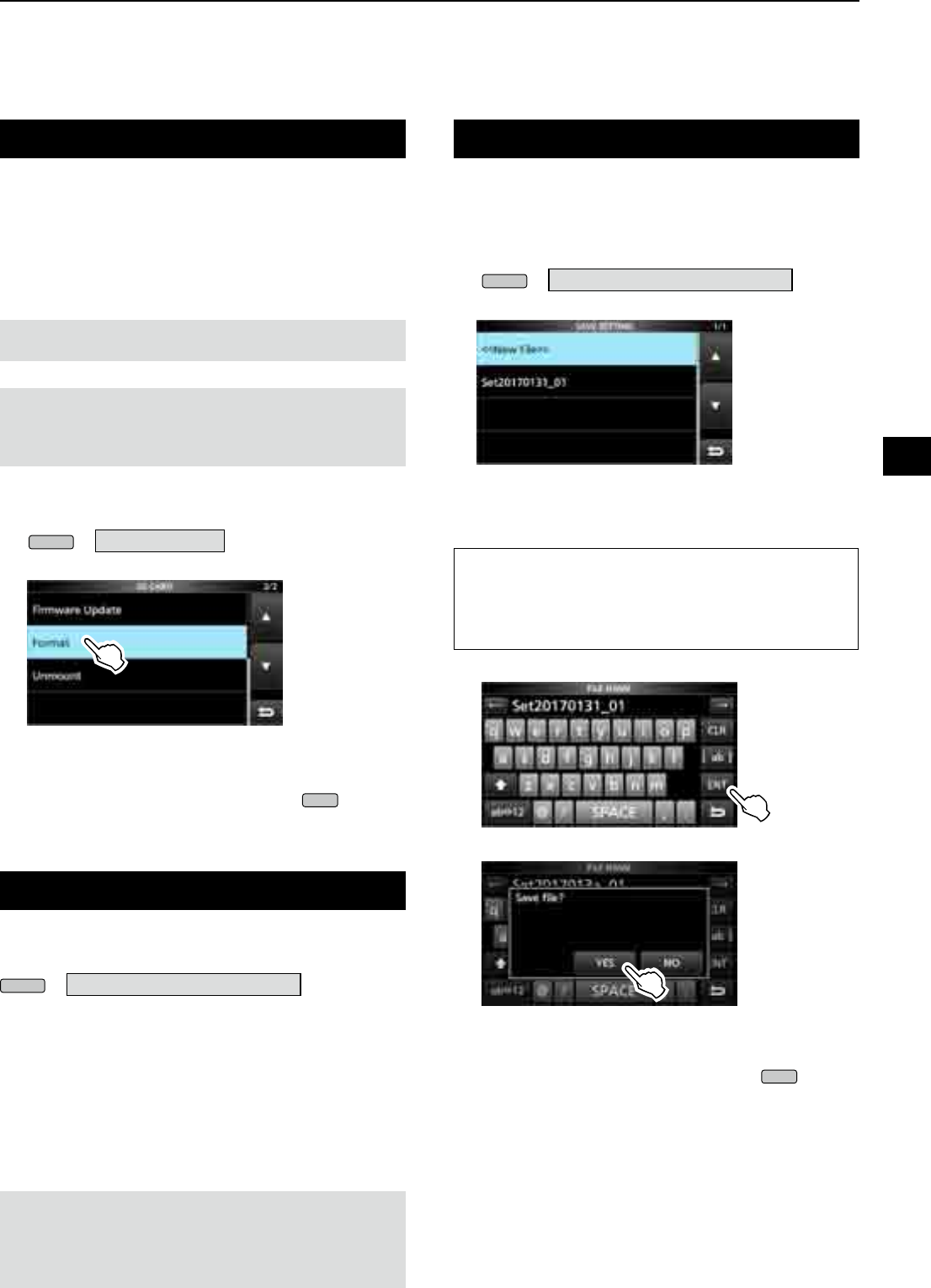
7
USING AN SD CARD
1
2
3
4
5
6
7
8
9
10
11
12
13
14
15
16
17
18
19
20
21
7-2
Formatting an SD card
Before using an SD card with the receiver, be sure to
format all SD cards with the built-in Format function.
This creates a special folder on the card that you need
for operations like updating the rmware.
Format all cards, including a brand new SD card, and
even preformatted cards for PCs or other uses.
NOTE: Formatting a card erases all its data. Before
formatting any used card, back up its data onto your PC.
IMPORTANT: Even if you format an SD card, some data
may remain in the card. When you dispose the card, be
sure to physically destroy it to avoid unauthorized access
to any data that remains.
1. Insert an SD card into the card slot.
2. Open the SD CARD set screen.
MENU
» SET > SD Card
3. Touch [Format].
• The format conrmation dialogue appears.
4. Touch [YES] to start formatting.
• After formatting, returns to the SD CARD screen.
5. To close the SD CARD screen, push
EXIT
several
times.
After you update the receiver’s rmware, the “Save
Form” item will be added on the SD CARD screen.
MENU
» SET > SD Card > Save Form
With this item, you can select the rmware version to
save the setting data onto an SD card.
You can write the setting le that is saved in an earlier
version to an earlier rmware version IC-R8600.
L Depending on the receiver’s rmware version, this
item may not be displayed. In that case, save the
le in the current version.
LSee page 13-1 for details of the rmware update.
NOTE:
•
If you select “Old Ver (xxx - xxx),” a function that is added when
the receiver’s rmware format is updated will not be saved.
• You cannot write a setting le that is saved in the current
version format to an earlier rmware version IC-R8600.
You can save the Memory channels and the receiver’s
settings onto an SD card.
1. Insert an SD card into the card slot.
2. Open the SAVE SETTING screen.
MENU
» SET > SD Card > Save Setting
3. Select “<<New File>>.”
SAVE SETTING screen
L The le name is automatically set in the following
format: Setyyyymmdd_xx (yyyy: Year, mm: month, dd:
day, xx: serial number)
TIP: After you update the receiver’s rmware, the “Save
Form” item will be added on the SD CARD set screen.
If this item is set to the earlier rmware version, the
conrmation window is displayed. When you want to save
the data in the earlier rmware version, touch [YES].
4. Touch [ENT].
5. Touch [YES].
• Saves the data settings.
L While saving to the card, the SD card icon blinks.
L After saving, returns to the SD CARD screen.
6. To close the SD CARD screen, push
EXIT
several
times.
Saving the setting data
Saving in the old format
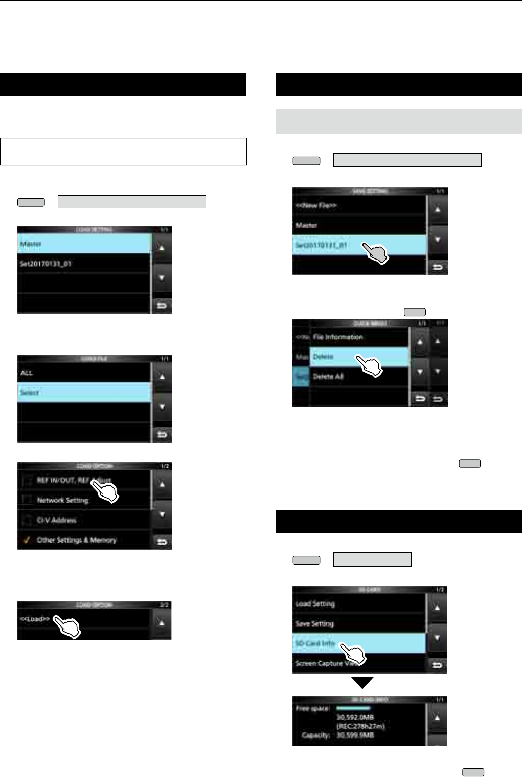
7USING AN SD CARD
7-3
Loading the data les
You can load the Memory channels and receiver’s
settings from the card to the receiver.
TIP: Saving the current data is recommended before
loading other data into the receiver.
1. Open the LOAD SETTING screen.
MENU
» SET > SD Card > Load Setting
2. Select the file you want to load.
LOAD SETTING screen
3. Select a loading option.
L Choose “ALL” when you load all the receiver settings.
4. Touch the desired loading items.
• “✓” is displayed left side of the selected option.
L The Set mode settings and Memory channel contents
are always loaded.
5. Touch “<<Load>>.”
• The load conrmation dialogue appears.
6. Touch [YES].
• Starts le loading.
L When you select “REF IN/OUT, REF Adjust” in step 4,
“The new "REF IN/OUT, REF Adjust" setting will be
saved” is displayed.
7. After the loading has been completed, “Restart the
IC-R8600” is displayed.
L Turn OFF the receiver power, then turn ON again.
Deleting a data le
NOTE: Deleted data from a card cannot be recalled.
Before deleting any data, back up the card data onto your PC.
1. Open the SAVE SETTING screen.
MENU
» SET > SD Card > Save Setting
2. Touch the file desired to delete for 1 second.
3. Touch “Delete.”
LTo delete all les, touch “Delete All.”
LTo cancel deleting, push
EXIT
.
• The delete conrmation dialogue appears.
4. Touch [YES].
• Deletes the selected le.
LAfter deleting, returns to the SAVE SETTING screen.
5. To close the SD CARD screen, push
EXIT
several
times.
Checking SD card information
1. Open the SD CARD screen.
MENU
» SET > SD Card
2. Touch to select “SD Card Info.”
• Opens the SD CARD INFO screen.
3. To close the SD CARD screen, push
EXIT
several
times.
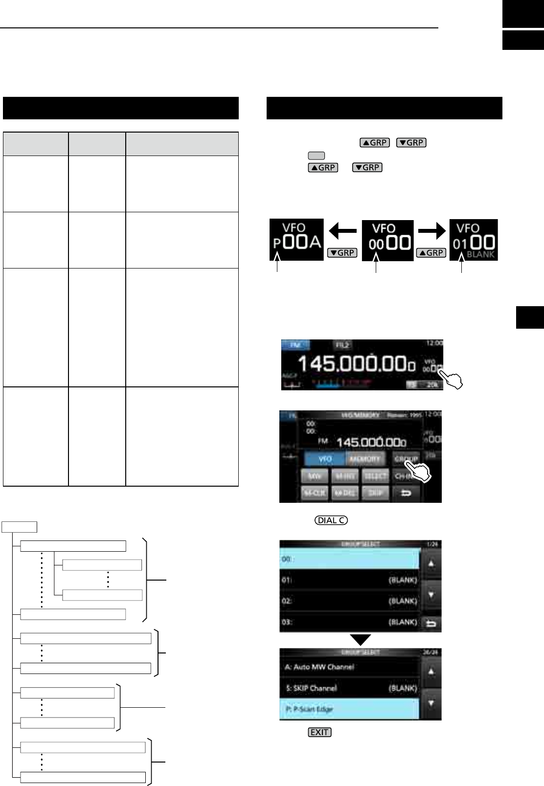
8-1
8
MEMORY OPERATION
Memory channels Selecting channel group
GROUPS MEMORY
CHANNELS USAGE
Group 00 ~ 99
(100 groups) 00 ~ 99
Has 100 memory groups.
L Up to 2000 channels can
be separately stored in
the 100 memory channel
groups.
Auto Memory
Write channels
A000 ~ A199
(200
channels)
Automatically stores
frequencies into each 200
channels when a signal is
received during an Auto
Memory Write scan.
Scan Skip
channels
S00 ~ S99
(100
channels)
100 scan skip channels
can be stored into the
memory channels. These
scan skip channels are
used for the Programmable
scan, Fine Programmable
scan, Auto Write Memory
scan, ∂F scan, Fine ∂F
scan and Programmable
Skip scan.
Program Scan
Edges
P00A /P00B
~
P49A/P49B
(50 pairs)
50 pair of scan edges
for the lower and upper
frequency edges can be
programmed.
L The same pair of
frequencies are written
as the default.
L You cannot clear nor
leave them blank.
DSelecting with /
1. Push
V/M
to select the Memory mode.
2. Push or to select the group.
L You can select only groups that contain a channel.
L In the VFO mode, you can select blank groups.
DSelecting
on the GROUP SELECT screen
1. Touch the Memory channel number.
2. Touch [GROUP].
3. Rotate and touch to select a memory
group (00 ~ 99, A, S or P).
4. Push to close the VFO/MEMORY screen.
Group No.
(Example:00)
Group No.
(Example:01)
Program scan edge
[Memory channel tree view]
1
2
3
4
5
6
7
8
9
10
11
12
13
14
15
16
17
18
19
20
21
Group
50 pairs
100 channels
200 channels
Up to 2000 channels*
*100 channels in each group
Memory Channel Group 00
Memory Channel Group 99
Auto Memory Write Channel A000
Auto Memory Write Channel A199
Program Scan Edge P00A/P00B
Program Scan Edge P49A/P49B
Memory Channel 00
Memory Channel 99
Scan Skip Channel S00
Scan Skip Channel S99
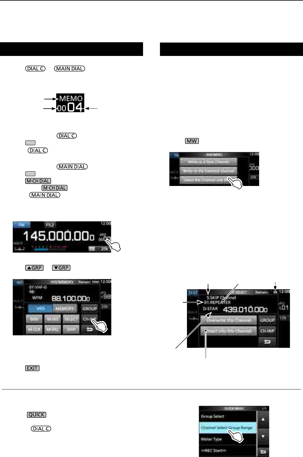
8MEMORY OPERATION
8-2
z Rotate or to select the desired
memory channel.
L Only the Memory channels that have contents are
displayed.
A single memory channel stores the frequency,
receive mode and IF lter width besides the following
items.
• Tuning step • DUP direction
• P.AMP ON/OFF • TSQL/DTCS setting
• ATT setting • DIGITAL Squelch settings
• Antenna setting • Memory name
• IP+ ON/OFF • SKIP Setting
• DUP mode • SELECT Setting
1. Set the frequency and receive mode and so on.
2. Push .
3. Touch to select the desired memory write option.
[Write to a New Channel]:
• The contents such as frequency and operating mode are
written to a blank channel in the selected group.
[Write to the Selected Channel]:
• The selected channel is overwritten.
[Select the Channel and Write]:
• The channel is written to the channel selected on the CH
SELECT screen.
Selecting a memory channel Writing a memory channel
(Example: Memory channel 04)
Memory mode
Group number Channel number
DSelecting with
1. Push
V/M
to select the Memory mode.
2.
Rotate to select the desired memory channel.
DSelecting with
1. Push
V/M
to select the Memory mode.
2. Push .
• LED on the key lights.
3. Rotate to select a memory channel.
DSelecting using the keypad
1. Touch the memory channel number.
• The VFO/MEMORY screen is displayed.
2. Push or to select the group.
3. Touch [CH-INP].
4. Touch the numeric keys to enter the desired
memory channel number.
5. Touch [ENT] to set the entered memory channel.
6. Push to close the VFO/MEMORY screen.
Memory write options
Number of
remaining blank
channels
Channel
number
Memory
contents
Group
Memory name
(if entered)
Insert a new channel without overwriting
the selected channel.
CH SELECT screen example
InformationL: Selecting a memory channel in a different group
You can select the desired Memory channel stored in all memory channel groups.
1. Push , and touch [Channel Select Group Range].
2. Touch [All Groups].
3. Rotate to continuously select a memory channel
in all memory channel groups.
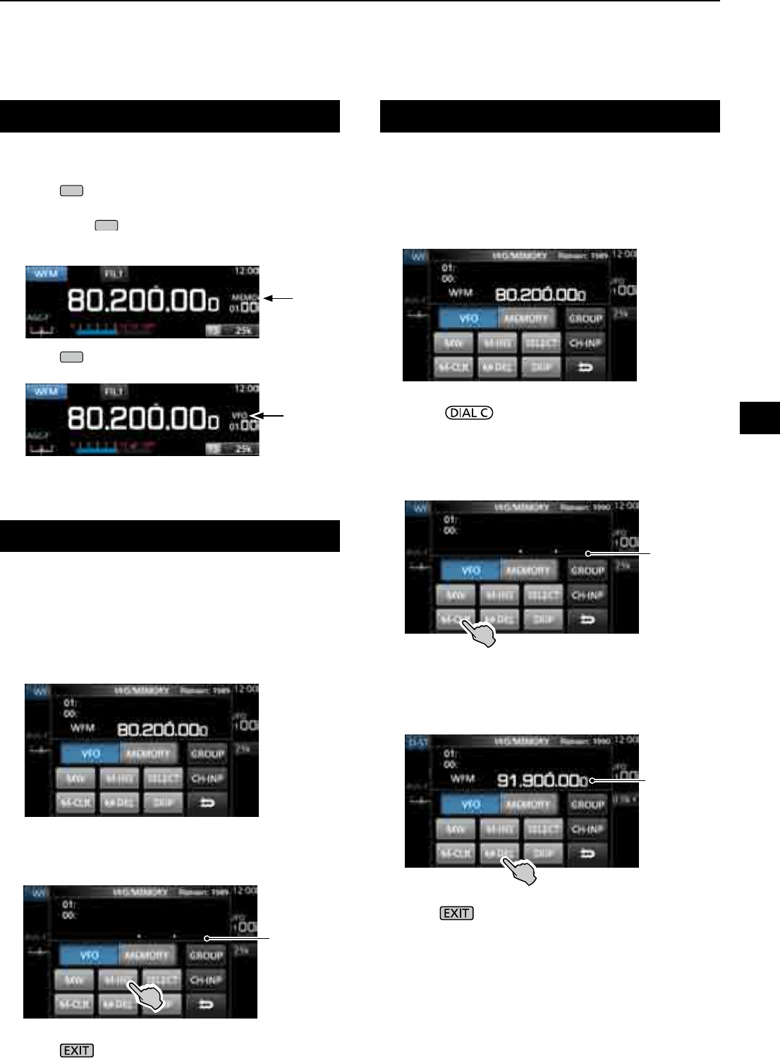
8-3
Clearing a memory channelCopying the Memory contents
Inserting a blank channel
When you clear a memory channel, you can choose
whether to leave the cleared channel blank as a place
holder, or keeping the deleted channel number.
LYou cannot clear program scan edge channels.
1. Touch the Memory channel number.
• The VFO/MEMORY screen is displayed.
2.
Rotate to select the channel you want to clear.
3. When clearing the memory channel contents:
zTouch [M-CLR] (Memory Clear) for 1 second.
• Beeps sound and the selected memory contents are
cleared but the memory channel remains as a blank
channel.
When deleting the channel:
zTouch [M-DEL] (Memory Delete) for 1 second.
• Beeps sound and the memory channel is completely
deleted.
4. Push to close the VFO/MEMORY screen.
You can copy the Memory contents to the VFO.
1. Push
V/M
to select the Memory mode.
2. Select the memory channel to be copied.
3. Hold down
V/M
for 1 second.
• Beeps sound and the selected memory contents are
copied to the VFO.
4. Push
V/M
to select the VFO mode to confirm that
the memory contents were successfully copied.
You can insert a blank channel between 2 Memory
channels.
L This function is convenient to organize your memory
channels.
1. Touch the Memory channel number.
• The VFO/MEMORY screen opens.
2. Select the channel to insert a blank channel below.
3. Touch [M-INS] for 1 second.
• Beeps sound and a blank channel is inserted below
the selected memory channel.
4. Push to close the VFO/MEMORY screen.
Memory
mode
VFO mode
Blank
channel
Blank
channel
Next channel
contents
8
MEMORY OPERATION
1
2
3
4
5
6
7
8
9
10
11
12
13
14
15
16
17
18
19
20
21
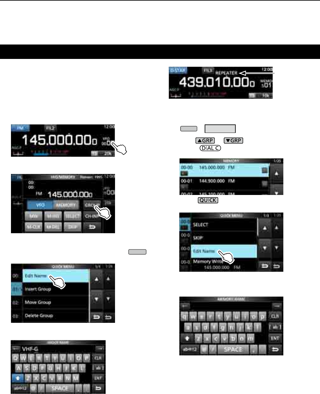
8MEMORY OPERATION
8-4
Entering a group/memory name
You can assign a name of up to 16 characters to each
channel group (00 ~ 99) and memory channel.
• You cannot change the group name of Auto MW, Skip and
scan channels (Groups "A," "S" and "P").
DEntering a group name
1. Touch the Memory channel number.
• The VFO/MEMORY screen opens.
2. Touch [GROUP].
3. Select the channel group to enter a name.
4.
While the channel group is selected, touch
QUICK
.
5. Touch “Edit Name.”
• The “GROUP NAME” editing screen is displayed.
6. Enter a name of up to 10 characters.
L See “Keyboard entering and editing” (p. 1-8) for
details.
7. Touch [ENT] to save the entered name.
• The MEMORY NAME screen closes and returns to the
GROUP SELECT screen.
DEntering a memory name
1. Open the MEMORY screen.
MENU
» MEMORY
2. Push or to select the group.
3. Rotate to select the channel to enter a
name.
4.
Touch .
5. Touch “Edit Name.”
• The “MEMORY NAME” editing screen is displayed.
6. Enter a name of up to 10 characters.
L See “Keyboard entering and editing” (p. 1-7) for details.
7. Touch [ENT] to save the entered name.
• The MEMORY NAME screen closes and returns to the
MEMORY screen.
Memory name
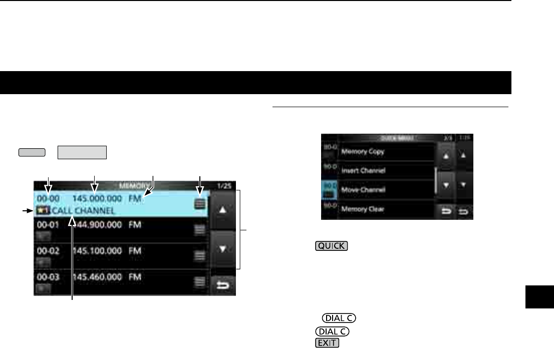
8-5
About the MEMORY screen
q Memory channel group and channel number
Displays the Memory group (00 ~ 99, A, S and P), and
Memory channel number (00 ~ 99, A000 ~ A199, S00
~ S99 and P00A/P00B ~ P49A/P49B) in each group.
w Frequency
Displays the entered frequency.
e Receive mode
Displays the selected receive mode.
r Memory menu
Touch to display the MEMORY MENU.
L “SKIP,” “Edit Name,” “Memory Write” or “Memory Clear”
is selectable.
t [▲]/[▼] key
Touch to scroll the memory channel list.
L To select a memory channel in a different group, refer
to page 8-2.
y Memory name
Displays the memory name, if entered.
L To assign a memory name, refer to page 8-4.
u Select memory icon
Touch this icon to set the Select number “1” ~
“9” or OFF.
L To clear the Select memory setting, touch this icon for
1 second, then select a clearing option.
You can edit the Memory channel contents on this screen.
z Open the MEMORY screen.
MENU
» MEMORY
wr
qe
y
u
t
Memory screen example
InformationL: You can also edit the memory channel
in the QUICK MENU.
Example: Moving or copying a memory channel
1. Push to open the QUICK MENU.
2. Select the channel you want to move or make a
copy of.
3. Open the QUICK MENU on the MEMORY
screen.
4. Touch [Move Channel] or [Memory Copy].
5. Rotate to select the destination channel.
6. Push .
7. Push to close the QUICK MENU.
8
MEMORY OPERATION
1
2
3
4
5
6
7
8
9
10
11
12
13
14
15
16
17
18
19
20
21
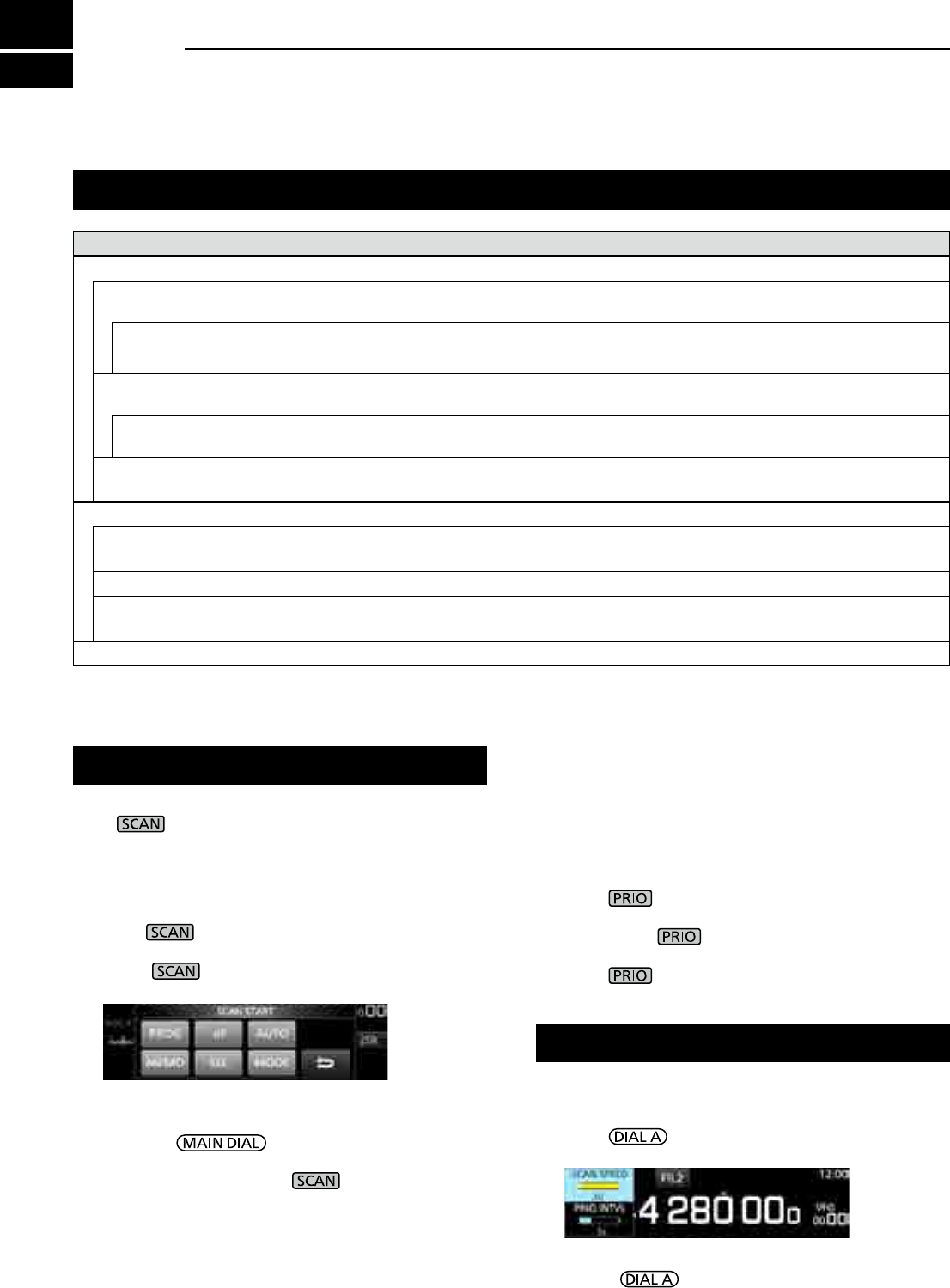
9-1
Scan types
Basic scanning
SCAN TYPE SCANNING DETAILS
VFO SCAN
PROGRAMMED SCAN Repeatedly scans between 2 Scan Edge frequencies of Program Scan Edge memory
channels. The scan starts from the lower edge frequency. (p.9-4)
FINE PROGRAMMED
SCAN
During a Programed scan, the scan speed decreases when the squelch opens, but the
receiver keeps scanning. The scan tuning step changes to 10 Hz when the squelch opens.
∂F SCAN Repeatedly scans within the ∂F span area. The scan starts from the center frequency, then
upper edge and lower edge. (p.9-5)
FINE ∂F SCAN During a ∂F scan, the scan speed decreases when the squelch opens, but the receiver
keeps scanning. The scan tuning step changes to 10 Hz when the squelch opens.
AUTO MEMORY WRITE
SCAN
During a Programed scan, and when a signal is received, the frequency is automatically
stored into an Auto Memory Write channel group. (p.9-6)
MEMORY SCAN
MEMORY SCAN Repeatedly scans memory channels, including Skip and Auto Write memory channels.
You can select the group and the scan edge channel. (p.9-7)
SELECT MEMORY SCAN Repeatedly scans all or one of 9 Select Memory channels. (p.9-7)
MODE SELECT MEMORY
SCAN
Repeatedly scans the memory channels with the selected receive mode (ignoring other
receive modes). (p.9-9)
PRIORITY SCAN Periodically monitors a selected memory channel while receiving a signal on VFO. (p.9-2)
Adjusting the scan speed
Adjust the scan speed for slower or faster scans.
1. Push .
• The setting menu opens.
2. Touch [SCAN SPEED].
3. Rotate .
• Setting range: 1 (slow) ~ 30 (fast)
L You cannot change the scan speed during a Fine
Program scan or Fine ∂F scan.
Push to start or stop a scan, then touch the
desired scan type.
L
See the following pages for the Scan setting details. (p. 9-3)
DVFO scan and Memory scan
1. Push .
• If you started a scan of the same scan type before, hold
down for a second, to start the same scan.
2. Touch the desired scan type.
• The SCAN screen opens, and the scan starts.
L
Rotating changes the scan direction:
Rotate right for the up scan, rotate left for the down scan.
L To cancel the scan, push .
L You can hide the SCAN screen during a scan. Set
[Display SCAN Screen (at SCAN START)] item to
"OFF" on the SCAN SETTING screen. (p. 9-3)
SCAN START screen
DPriority scan
Follow the procedure below to start or stop a Priority scan..
LSee page 9-2 for setting priority channel.
1. Push .
• "PRIO" is displayed.
L Hold down for 1 second to monitor the priority
channel.
2. Push again to cancel the scan.
9SCANS
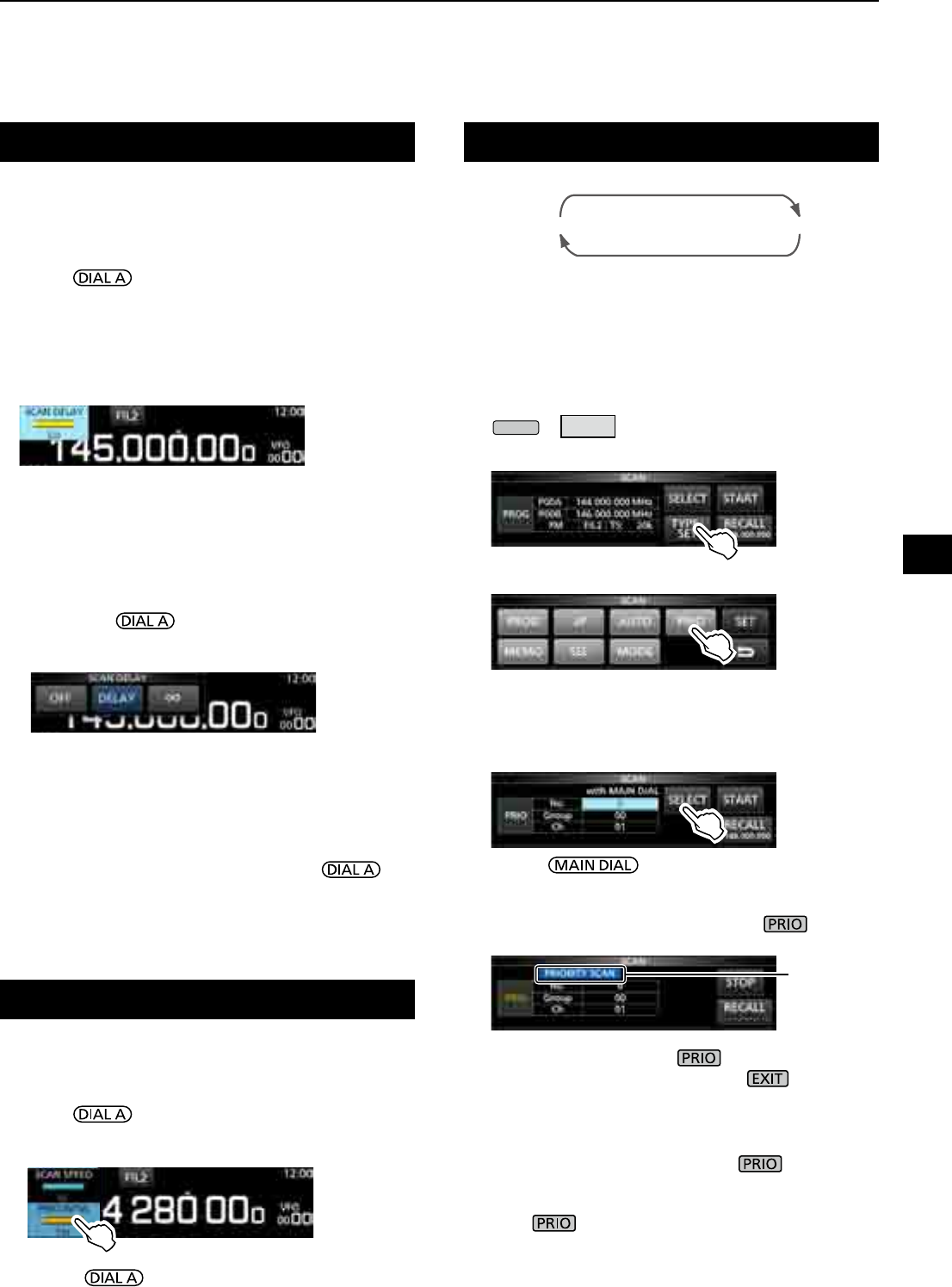
9-2
Priority scan
A priority scan periodically checks a selected memory
channel* while receiving on a VFO frequency.
* Memory channel, Auto Memory Write channel, Scan Skip
Channel or Program Scan Edge Channel.
DPriority scan operation
1. Open the SCAN screen.
MENU
» SCAN
2. Touch [TYPE/SET].
3. Touch [PRIO].
4. Touch [SELECT] to select the item to change.
• No.: Priority memory preset number (0 ~ 9)
(You can save up to 10 pairs of Group and Ch.)
• Group: Memory Group number
• Ch: Memory channel number.
5. Rotate to change the setting.
LYou cannot select blank channels.
6. Touch [SELECT] several times to exit the edit
mode, then touch [START] or push .
• A Priority scan starts.
• To cancel the scan, push or touch [STOP].
7. To close the SCAN screen, push .
DMonitoring the Priority channel
z During a Priority scan, hold down for
1 second to monitor the priority channel.
• "PRIO" is displayed while monitoring.
• Push to cancel the monitoring.
Setting the Scan Resume function
DSetting the Scan Resume function
You can set the Scan Resume options for when the
signal disappears.
1. Hold down for 1 second.
• The SCAN DELAY screen opens.
2. Touch the resume condition option.
• [OFF]: The scan pauses until the signal
disappears.
• [DELAY]: When a signal is received, the
scan pauses for the preset delay
period, then resumes.
(Set the delay by rotating .)
• [∞](Innity): Thescaniscancelledwhena
signal is received.
DSetting the scan delay timer
You can set the delay time that the scan restarts after
the signal disappears.
zRotate .
• Setting range: 1 ~ 30 seconds
LThe delay amount is displayed while setting.
L If a signal is received before the delay time has
expired, the timer restarts.
L When the Scan Resume function is set to [OFF] or [∞],
the scan delay is not activated.
90.6 MHz (VFO)
Blinks
SCAN screen
Setting the priority interval
Priority scan checks the priority channel according to
the set interval.
1. Push .
• The setting menu opens.
2. Touch [PRIO INTVL].
3. Rotate .
• Setting range: 1 ~ 15 seconds
9
SCANS
1
2
3
4
5
6
7
8
9
10
11
12
13
14
15
16
17
18
19
20
21
(Example)
145 MHz (Memory channel)
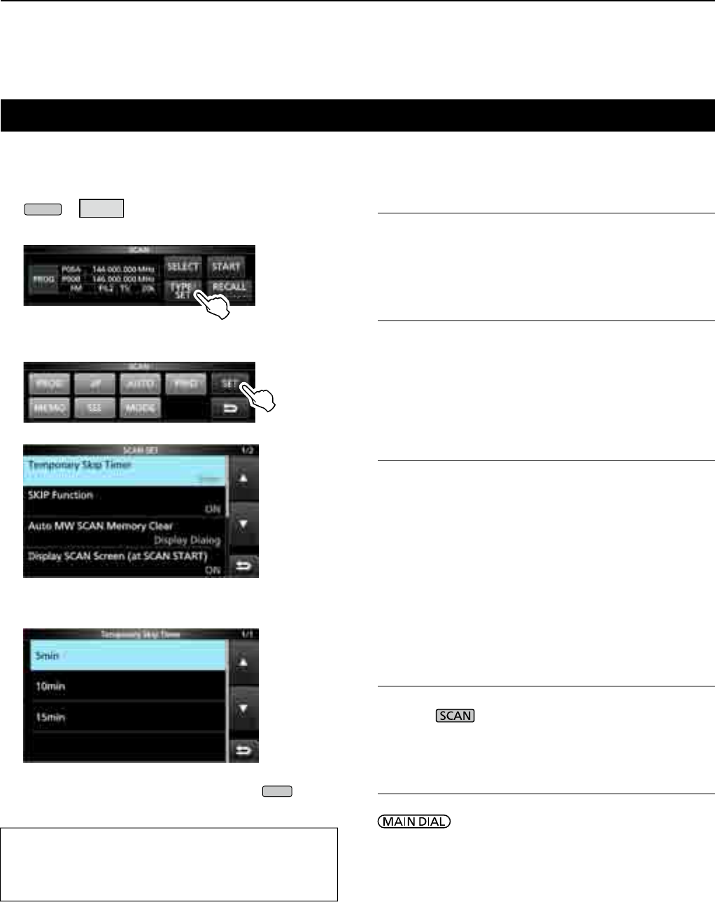
9SCANS
9-3
Temporary Skip Timer (Default: 5min)
Sets the period of time of the Temporary Skip timer.
The Skip timer ignores the Temporary Skip signal for
the set period of time.
• Options: 5, 10 and 15 minutes
SKIP function (Default: ON)
Sets the Skip (SKIP or PSKIP) function.
• OFF: Turns OFF the function.
(You can use the Temporary Skip function (p. 9-10).)
• ON: The scan skips the memory channels that are
programmed as skip channels.
Auto MW (Memory Write) SCAN Memory Clear
(Default: Display Dialog)
Selects the option to start an Auto Memory Write Scan.
• OFF: Starts an MW scan without clearing Auto
Write memory channels (A000 ~ A199).
• Display Dialog:
Asks whether or not to clear Auto Write
memory channels (A000 ~ A199) before
starting an MW scan.
• ON: Automatically clears Auto Write memory
channels (A000 ~ A199) before starting an
MW scan.
Display SCAN Screen (at SCAN START)
(Default: ON)
Selects whether or not to display the SCAN screen when
you push to start a scan (except Priority scan).
• OFF: Does not display the SCAN screen.
• ON: Displays the SCAN screen.
MAIN DIAL Operation (SCAN) (Default: Up/Down)
Selects the scan operation when you rotate
during a scan.
• OFF: Cancels the scan.
• ON: Changes the scan direction.
Rotate right for an up scan, rotate left for a
down scan.
Scan Setting screen
ConguretheScanontheScanSettingscreen.
1. Open the SCAN screen.
MENU
» SCAN
2. Touch [TYPE/SET].
3. Touch [SET].
4. Touch to select the desired item.
5. Touch to select the desired option.
L See the right column for setting items and options.
6. To close the SCAN SET screen, push
EXIT
.
TIP: How to reset to the default setting
Touching the item or its option for 1 second displays
the Quick menu, and then touch “Default” to reset to
the default settings.
SCAN screen
SCAN SET screen
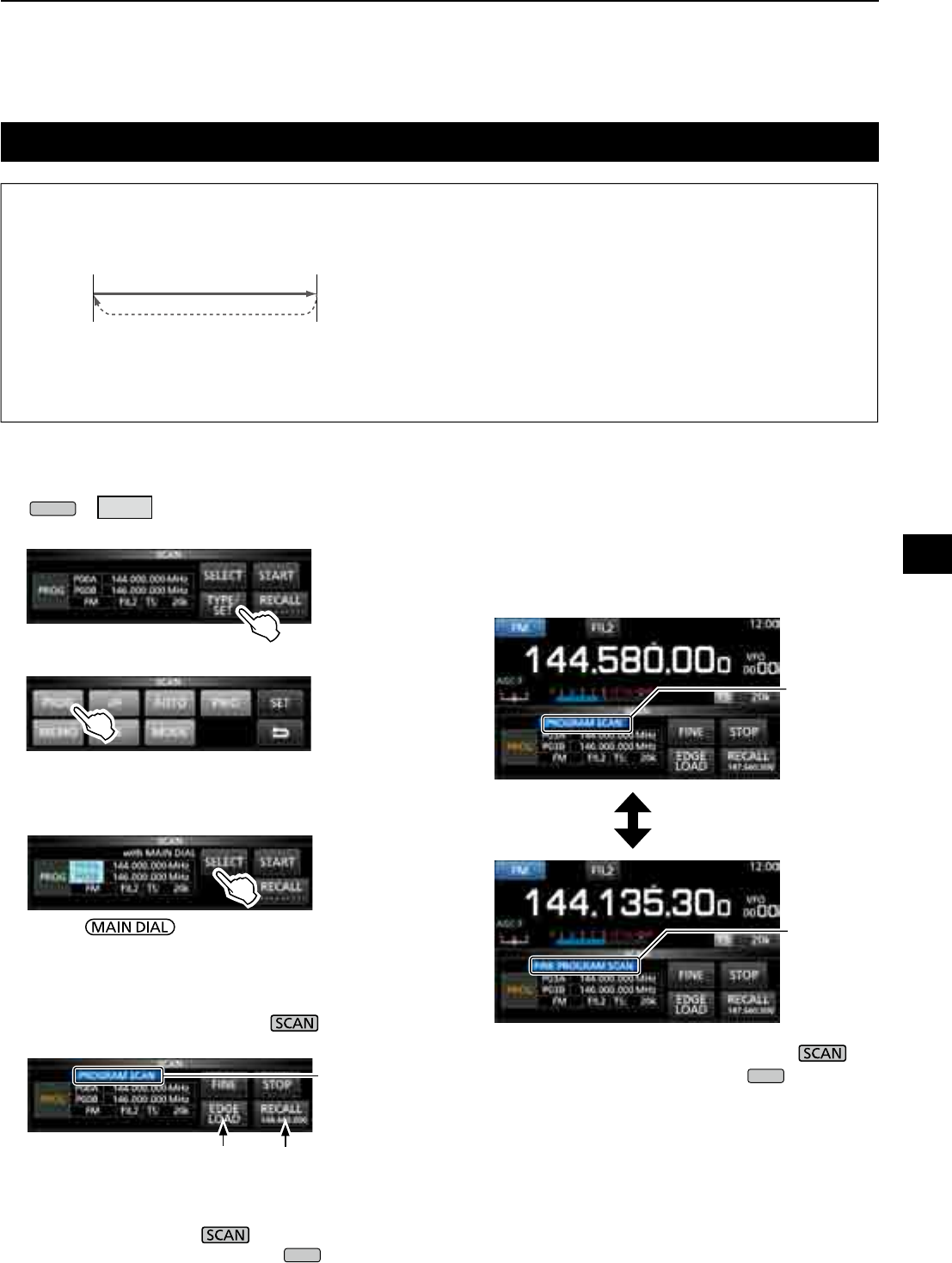
9-4
Programmed scan and Fine Programmed scan
Programmed scan and Fine Programmed scan
Repeatedly scans between two Scan Edge
frequencies (
P00A/P00B ~ P49A/P49B).
L To change the Scan Edge Memory channels, see
“Writing a memory channel” for details. (p. 8-2)
L If the both Scan Edges are the same frequencies,
the Programmed scan does not start.
L In the Fine Programmed scan, the scan speed
decreases when the squelch opens, but the
receiver keeps scanning. The scan tuning step
changes to 10 Hz when the squelch opens.
DProgrammed scan operation
1. Open the SCAN screen.
MENU
» SCAN
2. Touch [TYPE/SET].
3. Touch [PROG].
4. Touch [SELECT] to select the item* to change,
* Scan edge channel number (Example: P00A/P00B),
scan edges (lower and upper frequencies), receive
mode,lterandtuningstep(TS).
5. Rotate , or to touch [EDIT] to change
the setting.
L The changed settings are stored in the Program Scan
Edge channel.
6.
Touch [SELECT] several times to exit the edit mode,
then touch [START] or hold down for 1 second.
• The Programmed scan starts.
LTouch [STOP] or push to cancel the scan.
7. To close the SCAN screen, push
EXIT
.
DFine Programmed scan operation
1. Start a Programmed scan.
L See steps 1 ~ 6 in “Programmed scan operation” to
the left for details.
2. While Programmed scanning, touch [FINE].
L Each touch toggles the Programmed scan and the
Fine Programmed scan.
LTo cancel the scan, touch [STOP] or push .
3. To close the SCAN screen, push
EXIT
.
Blinks
Recalls the VFO
frequency before
the scan starts
Jumps to the lower edge
While Programmed scanning
While Fine Programmed scanning
Blinks
Blinks
9
SCANS
1
2
3
4
5
6
7
8
9
10
11
12
13
14
15
16
17
18
19
20
21
P00A
144 MHz P00B
148 MHz
(Example) P00A/00B
Scan
Jump
Lower
edge
Upper
edge
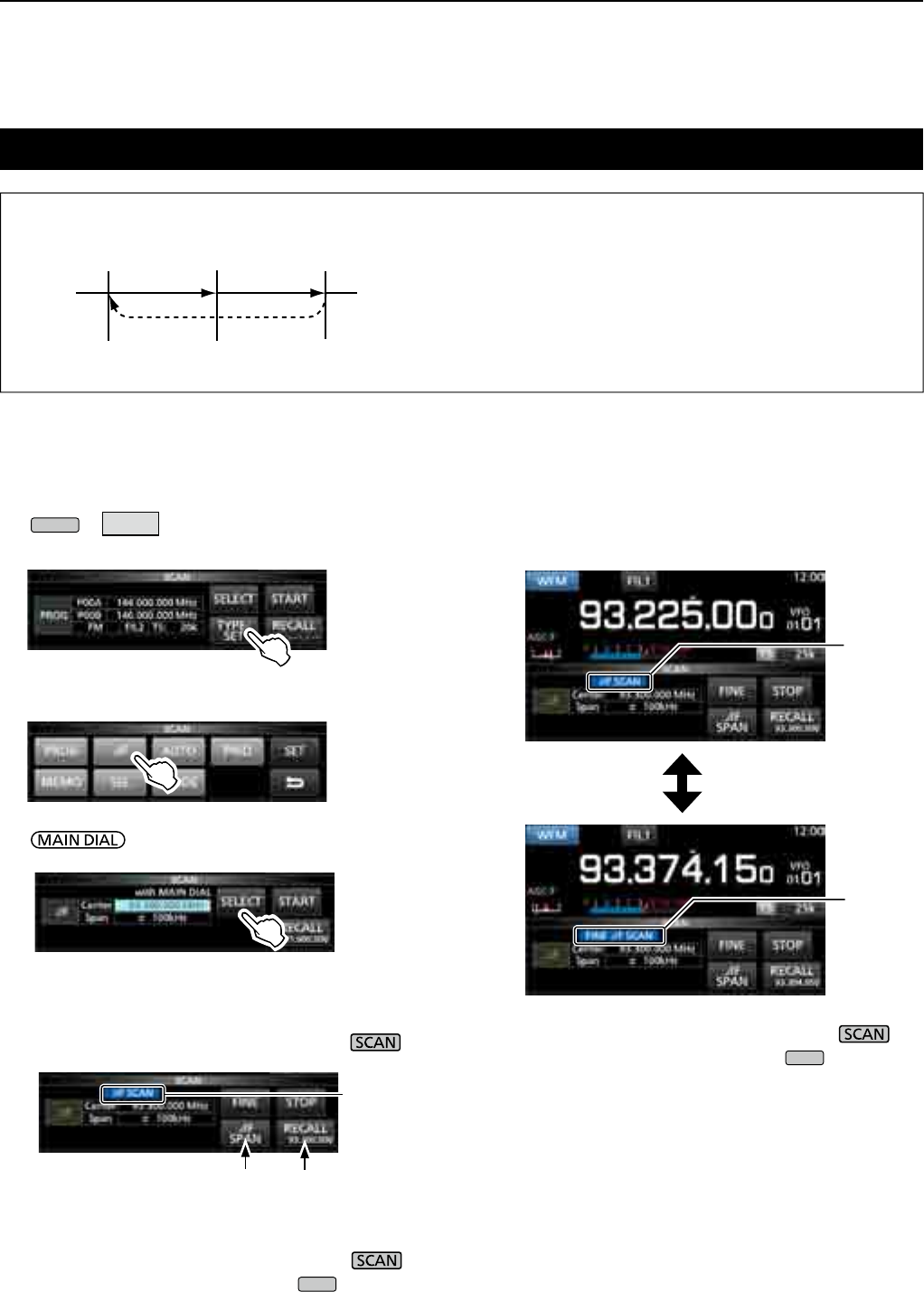
9SCANS
9-5
∂F scan
∂F scan and Fine ∂F scan
100 kHz 100 kHz
93.3 MHz 93.4 MHz93.2 MHz
Repeatedly scans within the ∂F span area.
The scan starts from the center frequency of VFO or
selected memory channel.
LInne∂F scan, the scan speed decreases
when the squelch opens, but the receiver keeps
scanning. The scan tuning step changes to 10 Hz
when the squelch opens.
D∂F scan operation
1. Select the VFO or Memory mode, then set the
center frequency of the scan.
2. Open the SCAN screen.
MENU
» SCAN
3. Touch [TYPE/SET].
4. Touch [∂F].
5. Touch [SELECT] to select the item, then rotate
to change the setting.
• Set the center frequency and span.
L The scan does not start when the tuning step is wider
than the span.
6.
Touch [SELECT] several times to exit the edit
mode, then
t
ouch [START]
or hold down for
1 second.
to start the ∂F scan.
LTo cancel the scan, touch [STOP] or push .
7. To close the SCAN screen, push
EXIT
.
DFine ∂F scan operation
1. Start the ∂F scan.
L See steps 1 ~ 6 in “∂F scan operation” to the left for
details.
2. While ∂F scanning, touch [FINE].
• Each touch toggles the ∂F scan and the Fine ∂F scan.
LTo cancel the scan, touch [STOP] or push .
3. To close the SCAN screen, push
EXIT
.
While ∂F scanning
While Fine ∂F scanning
Blinks
Blinks
Blinks
Recalls the VFO
frequency before
the scan starts
Jumps to the lower edge
SCAN screen
(Example) Span: 100 kHz
Start
Jump
Lower
edge
Upper
edge
Center
frequency
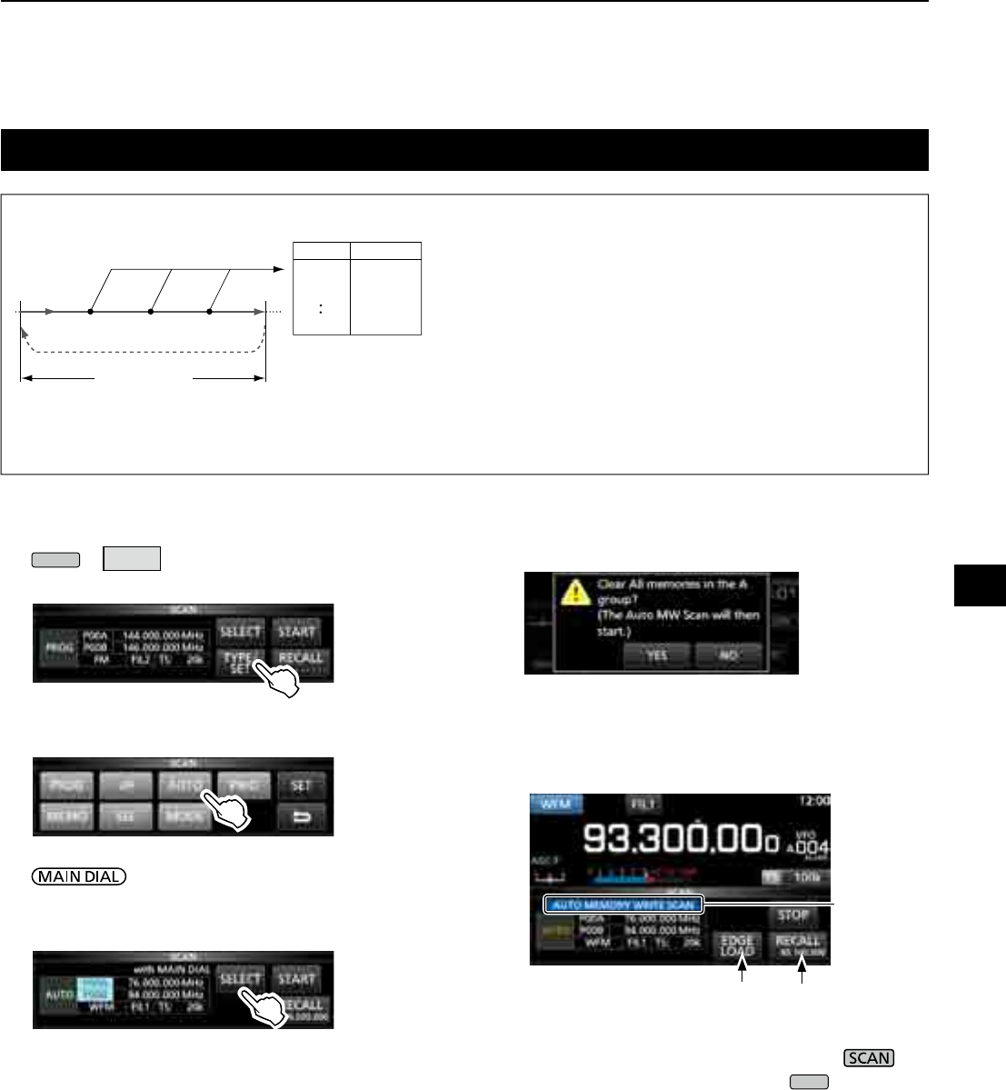
9-6
Auto Memory Write scan
DAuto Memory Write scan operation
1. Open the SCAN screen.
MENU
» SCAN
2. Touch [TYPE/SET].
3. Touch [AUTO].
4. Touch [SELECT] to select the item*, then rotate
to change the settings.
* Program Scan Edge number (Example: P00A/P00B),
scan edges (lower and upper frequencies), receive
mode,lterandtuningstep(TS).
L The changed settings are stored in the Program Scan
Edge channel.
Auto Memory Write scan
When a signal is received during a Programmed scan, the
frequency is automatically stored into an Auto Memory
Write channel group (A000 ~ A199).
L When no blank channels is left in group A (A000 ~ A199),
the Auto Memory Write scan automatically cancels.
You can clear the all channels in group A (A000 ~ A199)
every time you start a Auto Memory Write scan.
See page 9-3 for details.
L The channels in group A (A000 ~ A199) are automatically
aligned at the top, and all the blank channels are
removed (A000 ~ A199).
5. Touch [SELECT] several times to exit the edit
mode, then touch [START].
• Theconrmationdialogisdisplayed.
6. Touch [YES].
• The Auto Memory Write scan starts.
L If you do not want to clear the memory channels in
the group A (A000 ~ A199), touch [NO].
LTo cancel the scan, touch [STOP] or push .
7. To close the SCAN screen, push
EXIT
.
A000
A002
A001
A199
85.100
80.200
76.500
– – –
– – –
Blinks
Recalls the VFO
frequency before
the scan starts
Jumps to the lower edge
SCAN screen
9
SCANS
1
2
3
4
5
6
7
8
9
10
11
12
13
14
15
16
17
18
19
20
21
Scanning
Scan range
Jump
Signal
received Signal
received
Auto MW CH group
Channel Frequency
Signal
received
The received signal frequency is stored
into an Automatic Memory Write group
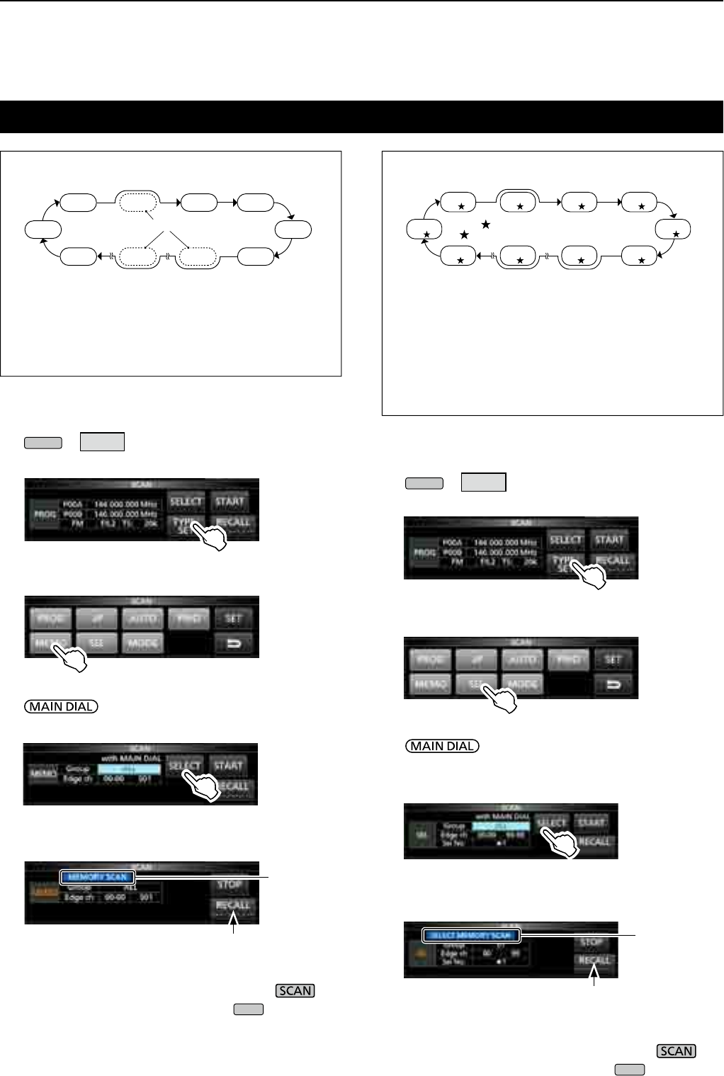
9SCANS
9-7
Memory scan and Select Memory scan
Memory scan
99ch
00ch 01ch 02ch 03ch
04ch
05ch06ch50ch98ch
Repeatedly scans all entered Memory channels
except Program Scan Edges.
LYou can scan memory channels only in the desired group.
LBlank channels are skipped.
L If two or more Memory channels are not entered, the
Memory scan does not start.
Select Memory scan
99ch
1
00ch
101ch
202ch
103ch
1
04ch
1
05ch
1
06ch
2
50ch
3
98ch
1
Repeatedly scans all or one of 9 Select Memory
channels (★1 ~ ★9) that are assigned as Select
Memory channels.
L You can scan Select Memory channels only in the
desired group.
L If two or more Memory channels are not assigned as a
Select Memory channels, the Select Memory scan does
not start.
DMemory scan operation
1. Open the SCAN screen.
MENU
» SCAN
2. Touch [TYPE/SET].
3. Touch [MEMO].
4. Touch [SELECT] to select the item, then rotate
to change the setting.
• Set the channel group* and edge channels.
* If you do not specify the group, set [Group] to "ALL."
5. Touch [SELECT] several times to exit the edit
mode, then touch [START].
• The Memory scan starts.
LTo cancel the scan, touch [STOP] or push .
6. To close the SCAN screen, push
EXIT
.
DSelect Memory scan operation
1. Open the SCAN screen.
MENU
» SCAN
2. Touch [TYPE/SET].
3. Touch [SEL].
4. Touch [SELECT] to select the item, then rotate
to change the setting.
• Set the channel group*, edge channels and the Select
Scan number (Sel No.).
* If you do not specify the group, set [Group] to "ALL."
5. Touch [SELECT] several times to exit the edit
mode, then touch [START] to start the Select
Memory scan.
LTo cancel the scan, touch [STOP] or push .
6. To close the SCAN screen, push
EXIT
.
SCAN screen
SCAN screen
Blinks
Deactivated
during a Memory
scan
Blinks
Deactivated
during a Memory
scan
(Example) Group: ALL (Each channel is in the different group.)
Blank channels are skipped Only " " tagged channels are scanned.
"" indicates the Selected (Tagged) Channel.
(Example) Group: ALL (Each channel is in the different group.)
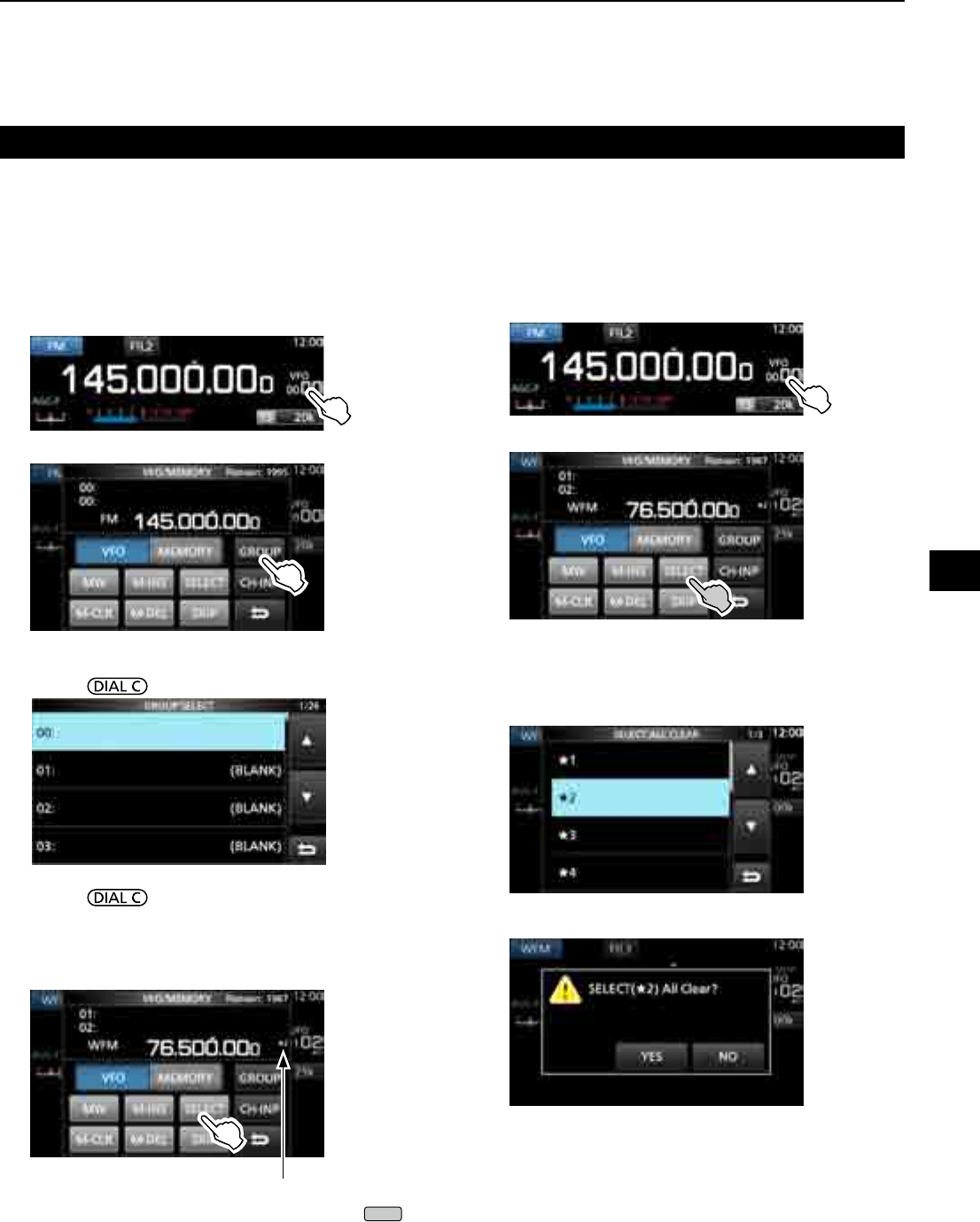
9-8
Memory scan and Select Memory scan (Continued)
DSetting Select Memory channels
Repeatedly scans only Memory channels that are
assigned as Select Memory channels (★1 ~ ★9).
L You cannot assign the Programed Scan Edge channels
(P00A/P49A ~ P00B/P49B) as Select Memory channels.
1. Touch the memory channel number.
2. Touch [GROUP].
3. Rotate , then touch to select the group.
4. Rotate to select the Memory channel you
want to assign as a Select Memory channel.
5. Touch [SELECT] to set the Select scan number.
L Each touch changes between“★1” to “★9,” and “(no
icon).”
6. To close the VFO/MEMORY screen, push
EXIT
.
D Canceling the Select Memory channel
settings
You can cancel the select memory setting, by removing
the Select Memory channel assignment (★1 ~ ★9).
1. Touch the memory channel number.
2. Touch [SELECT] for 1 second.
3. Touch the desired option to cancel the Select
setting.
L Touch [All] to cancel all Select settings (★1 ~ ★9) at
a time.
4. Touch [YES] to cancel the Select setting.
L The selected Select setting is canceled and returns to the
previous display.
VFO/MEMORY screen
Displayed
VFO/MEMORY screen
9
SCANS
1
2
3
4
5
6
7
8
9
10
11
12
13
14
15
16
17
18
19
20
21
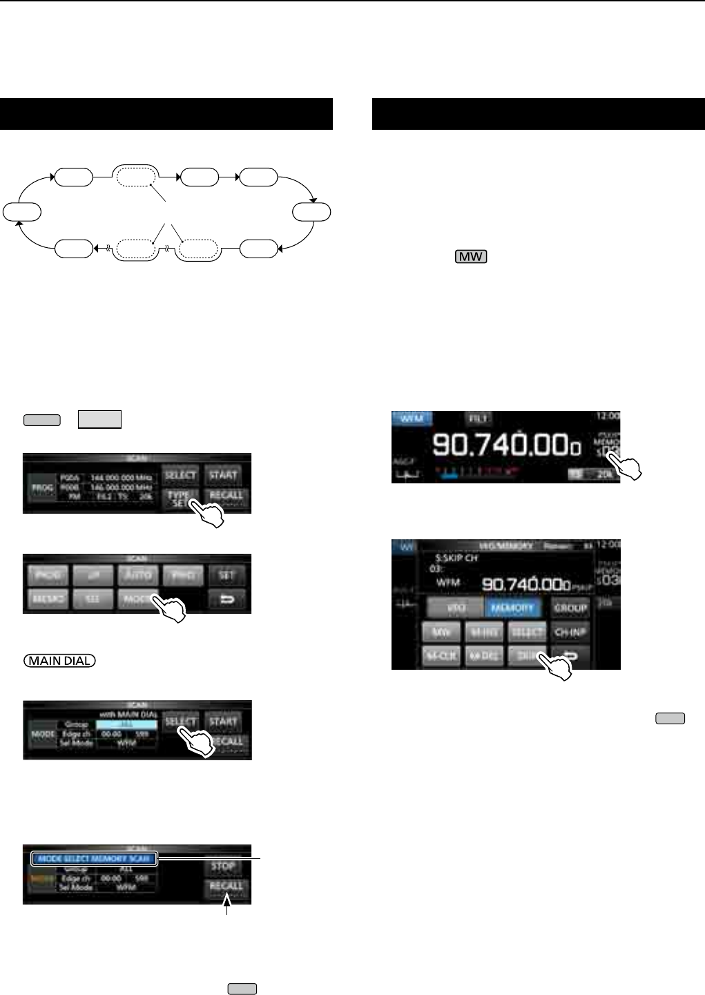
9SCANS
9-9
Mode select memory scan Setting the skip frequency
Repeatedly scans the selected receive mode (ignoring
other modes) while memory scanning, except
Programed Scan Edge channels (P00A/P49A ~ P00B/
P49B).
DSetting the receive mode
1. Select the receive mode.
2. Open the SCAN screen.
MENU
» SCAN
3. Touch [TYPE/SET].
4. Touch [MODE].
5. Touch [SELECT] to select the item, then rotate
to change the setting.
• Set the channel group and edge channels.
LYou cannot change the receive mode on this screen.
6. Touch [SELECT] several times to exit the edit
mode, then touch [START].
• The mode select memory scan starts.
L “MODE SELECT MEMORY SCAN” and decimal
points blink while scanning.
• Touch [STOP] to cancel the scan.
7. To close the SCAN screen, push
EXIT
.
You can set a frequency as a skip frequency that is
skipped (ignored) during a VFO scan*.
* Programmed scan, Fine Programmed scan, Auto Write Memory
scan, ∂F scan and Fine ∂F scan
DSetting the skip frequency
z Hold down for 1 second while a signal is
received and the scan is paused.
• The frequency is stored as the Scan Skip channel (S00
~ S99).
L The “PSKIP (Program SKIP)” is displayed on the skip
channel.
LDuring a VFO scan, the skip frequency is not skipped.
DCanceling the skip frequency
1. Touch the memory channel number.
2. Touch [SKIP].
L Each touch changes between “SKIP,” “PSKIP” and
“(no icon).”
L"PSKIP" disappears and the skip setting is cancelled.
3. To close the VFO/MEMORY screen, push
EXIT
.
SCAN screen
Blinks
Deactivated
during a Memory
scan
VFO/MEMORY screen
99chWFM WFM
00ch 01ch 02ch 03ch
WFM AM WFM WFM
WFM AM AM WFM
04ch
05ch06ch50ch98ch
(Example) Group: ALL (Each channel is in the different group.)
All modes except the
WFM are skipped.
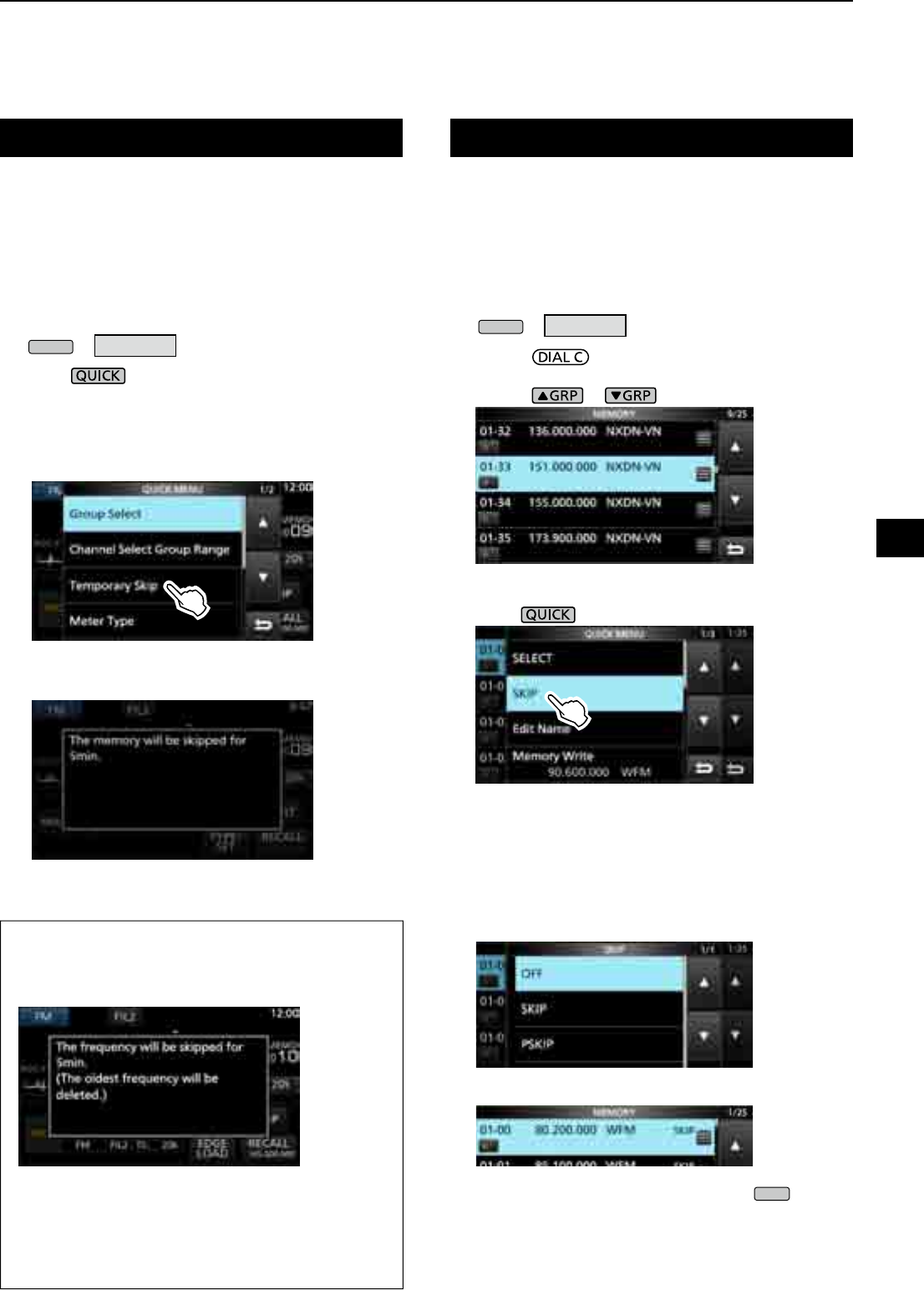
9-10
You can set a selected memory channel as a Skip
channel (SKIP or PSKIP) which is skipped during a
memory scan.
L You cannot assign the Programed Scan Edge channels
(P00A/P49A ~ P00B/P49B) as skip channels.
1. Open the MEMORY screen.
MENU
» MEMORY
2. Rotate and touch to select the memory
channel you want to set or clear the skip setting.
L Push or to change the group.
3. Push .
4. Touch [SKIP].
• The SKIP screen is displayed.
5. Touch the desired option.
• OFF: Clears the skip setting.
• SKIP: Skipped during a memory scan.
(Not skipped during a VFO scan.)
• PSKIP: Skipped during a VFO or memory scan.
• "SKIP" is displayed.
6. To close the MEMORY screen, push
EXIT
.
You can set a frequency as a temporary skip
frequency that is skipped (ignored) during a VFO
scan* or memory scan, for a period of time (default:
5 minutes).
* Programmed scan, Fine Programmed scan, Auto Write Memory
scan, ∂F scan and Fine ∂F scan.
1. Start a VFO or memory scan.
MENU
» MEMORY
2. Push .
• The QUICK MENU is displayed.
3. While the scan is paused and if you want to skip
the received signal, touch [Temporary Skip].
L If you touch during scan, a beep sounds and the
QUICK MENU closes.
• The Temporary Skip is set, then the scan resumes.
Skip channel for memory scanSetting the Temporary Skip
MEMORY screen
TIP: About the Temporary Skip
• You can set up to 5 skip frequencies.
When you set the 6th frequency, the oldest
frequency will be deleted.
• The Temporary Skip is canceled when:
- The time that is set to the Temporary Skip Timer
item (p. 9-3) has passed.
- You turn OFF the receiver power.
- You cancel the scan.
QUICK MENU
9
SCANS
1
2
3
4
5
6
7
8
9
10
11
12
13
14
15
16
17
18
19
20
21
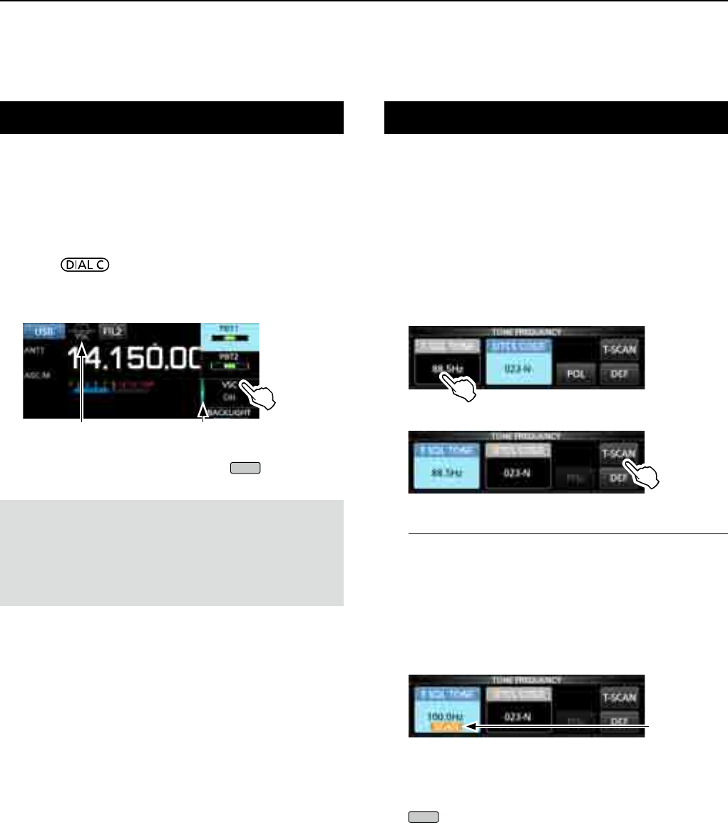
9SCANS
9-11
Tone scan operation
FM mode
The IC-R8600 can detect subaudible tone frequency or
the DTCS code in a received signal. You can determine
the tone frequency or DTCS code necessary to open
the squelch.
1. On the FUNCTION screen, touch [TONE] for
1 second.
2. Touch [T-SQL TONE] or [DTCS CODE].
(Example: T-SQL TONE)
3. Touch [T-SCAN].
• The Tone scan starts.
InformationL
• The selected tone frequencies or codes are scanned,
and “SCAN” blinks under the frequency readout.
• The audio is muted.
•
The scan speed is slow when the squelch is open, and is
fast when the squelch is closed.
4. When the tone frequency or code is detected, the
tone scan pauses.
• The detected frequency or code is automatically set.
5. To cancel the scan, touch [T-SCAN] again.
LThe last scanned tone frequency or code is displayed.
6. To close the TONE FREQUENCY screen, push
EXIT
.
Blinks
during scan
FM, WFM, AM and SSB modes
The Voice Squelch Control (VSC) function opens
the squelch, or stops the scan only when voice
components are detected in the signal.
LIt is convenient to receive only voice communications.
1. Push .
2. Touch [VSC].
• Each touch turns the VSC function ON or OFF.
• "VSC" appears when the function is ON.
3. To close the setting menu, push
EXIT
.
Voice Squelch Control function
LightsDisplayed
NOTE:
The VSC function is designed to not detect a continuous
audio signal. When receiving a signal such as a radio
broadcast program that contains a continuous audio, the
received audio may be broken up. In such case, turn OFF
the VSC function.
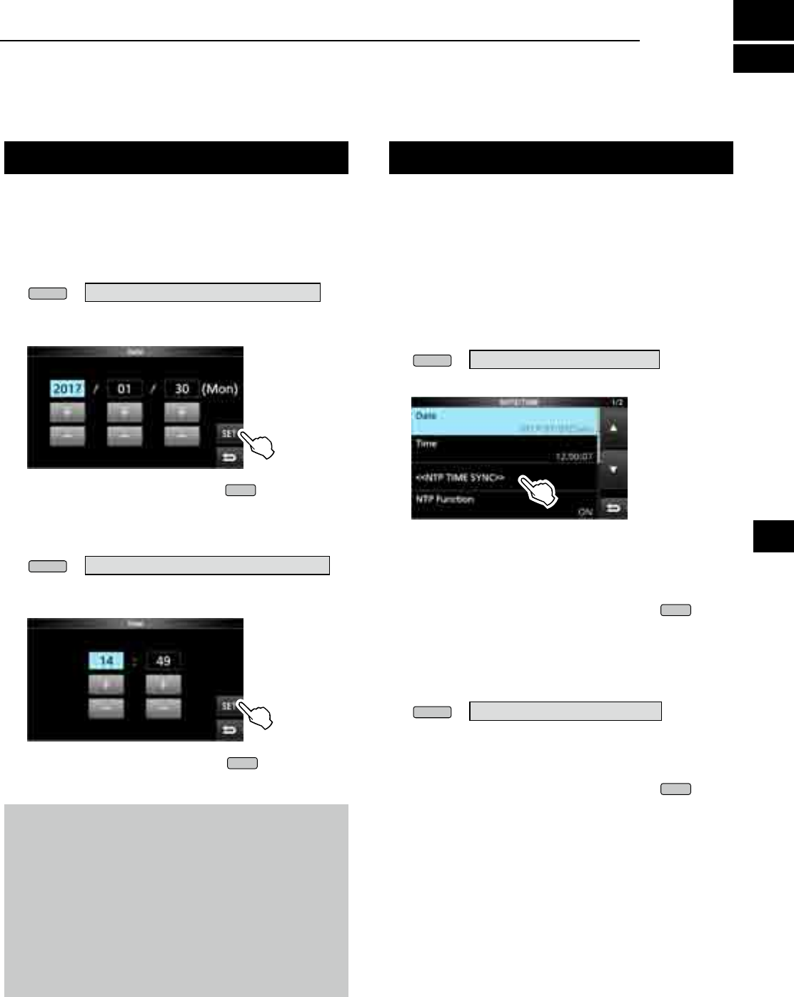
10-1
Setting the Time and Date NTP Time Server
NOTE: The backup battery for the internal clock
The IC-R8600 has a rechargeable Lithium battery to
backup the internal clock. If you connect the receiver to
a power source, the battery is charged and it keeps the
correct clock setting. However, if you do not connect the
receiver to a power source for a long period of time, the
battery will discharge. In that case, the receiver resets the
internal clock.
If you do not use the receiver for a long period, we
recommend that you connect the receiver to a power
source at least once a month. The charging period is two
days whether the receiver’s power is ON or OFF.
Manually set date and time without accessing the time
management server.
DSetting date
1. Open the Date screen.
MENU
» SET > Time Set > Date/Time > Date
2. Touch [+] or [–] to set the date.
3. Touch [SET] to store the entry.
4. To close the Date screen, push
EXIT
several times.
DSetting time
1. Open the Time screen.
MENU
» SET > Time Set > Date/Time > Time
2. Touch [+] or [–] to set the current time.
3. Touch [SET] to store the entry.
4. To close the Time screen, push
EXIT
several times.
The NTP function periodically synchronizes the
internal clock with the time management server.
L To use this function, an internet connection are necessary.
DExecute the time synchronization
The IC-R8600 accesses the NTP server address that
is set in the “NTP Server Address” item.
1. Open the DATE/TIME screen.
MENU
» SET> Time Set > Date/Time
2. Touch <<NTP TIME SYNC>>.
• The "Connecting to the NTP server" dialog is
displayed.
3. When the "Succeed" dialog is displayed, touch
[OK].
4. To close the DATE/TIME screen, push
EXIT
several times.
DSetting the NTP Server address
1. Open the DATE/TIME screen.
MENU
» SET > Time Set > Date/Time
2. Touch [NTP Server Address].
3. Enter the address using the keypad, then touch
[ENT].
4. To close the DATE/TIME screen, push
EXIT
several times.
10
CLOCK AND TIMER
1
2
3
4
5
6
7
8
9
10
11
12
13
14
15
16
17
18
19
20
21
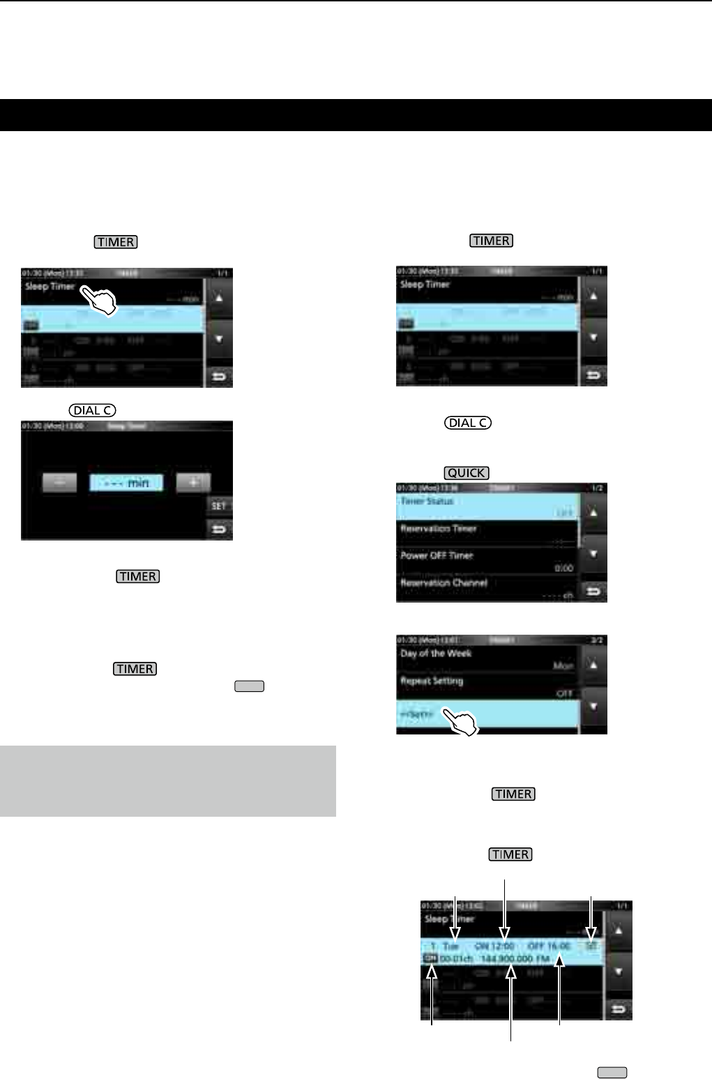
10 Clock and Timer
10-2
DSetting the Sleep timer
The Sleep timer automatically turns OFF the receiver
power after the set period of time ends.
• Settable range : 5 ~ 120 minutes (in 5 minutes steps)
1. Hold down for 1 second.
2. Touch [Sleep Timer].
3. Rotate to set the desired length of time.
4. Touch [SET].
• The timer LED lights orange.
• 10 seconds before the sleep timer period ends, the
receiver starts sounding beeps and the timer LED
blinking, then turns OFF.
L When the sleep timer ends, the time period set in
step 3 is cleared.
LEach push of stops and resumes the timer.
5. To close the TIMER screen, push
EXIT
several
times.
DSetting the Daily timer
The IC-R8600 automatically turns power ON or OFF
on the specied day and time.
LYou can set up to 3 timer slots for different timer setting.
1. Hold down for 1 second.
2. Touch to select a timer slot.
3. Rotate to set each item for the timer slot.
(Example: TIMER1).
LSee page 10-3 for each item's details.
LPush to reset to the default setting or cancel.
4. After you configure the Timer, touch [<<Set>>].
• The "Set Timer?" dialog appears.
5. Touch [YES].
• The timer LED lights orange.
L
When the Power OFF Timer is set: 10 seconds before
the sleep timer period ends, the receiver starts sounding
beeps and the timer LED blinking, then turns OFF.
LEach push of stops and resumes the timer.
6.
To close the TIMER screen, push
EXIT
several times.
Timer
TIMER screen
Timer activated
Reserved channel
Day of the week
Power OFF time
Power ON time Repeat ON
NOTE: About the Timer accuracy
Since the Sleep timer counts in ‘minute’ steps (not
counts in ‘second’ steps), it may have maximum 59
seconds of error.
10-3
Timer Status (Default: OFF)
Turns this timer slot ON or OFF. Set to ON to activate
the Timer.
L is displayed in the slot while the Timer is activated.
Reservation Timer (Default: 00:00)
Sets the time to turn ON the power in the 24-hour clock.
L If you use the Timer to turn OFF the power, push
then touch [Clear] to clear the Reservation Timer.
Power OFF Timer (Default: --:--)
Sets the time to turn OFF the power in the 24-hour clock.
L If you use the timer to turn ON the power, push
then touch [Clear] to clear the Power OFF Timer.
Reservation Channel (Default: ----)
Selects the memory channel number that is displayed
on start up. When Reservation Timer is set to ON, the
IC-R8600 starts with the selected memory channel.
L You can select any memory channel except blank one.
L If you want to start with currently selected memory
channel, push then touch [Clear].
L Even if the receiver power is ON, the currently selected
memory channel is automatically changed to the selected
memory channel.
Day of the Week (Default: ---)
Selects the day of the week to activate the Timer
every week.
• If you want to activate the Timer everyday, push
then touch [Clear].
Repeat Setting (Default: OFF)
Selects the timer repeat option.
• OFF: The timer activates only once.
( The Timer Status item is automatically reset to
"OFF," after the Timer has been activated.)
• ON: The Timer activates everyday, or every week
if a day of the week is selected.
L is displayed in the slot when "ON" is selected.
<<Set>>
Touch to store the timer settings and starts the Timer.
Timer (continued)
DAbout the Timer recording
You can start the recording using the Timer.
zStart the recording then turn OFF the power.
• When the IC-R8600 is turned on by the Timer, the
recording is automatically starts, according to the preset
recording setting (p. 6-4).
DTimer setting items
NOTE:
If you set the Power OFF timer earlier than Reservation
Timer, the receiver will not automatically turn OFF.
For example, if Reservation Timer is set to "8:00" and
Power OFF timer is set to "7:30," the receiver will not
automatically turn OFF.
10
Clock and Timer
1
2
3
4
5
6
7
8
9
10
11
12
13
14
15
16
17
18
19
20
21
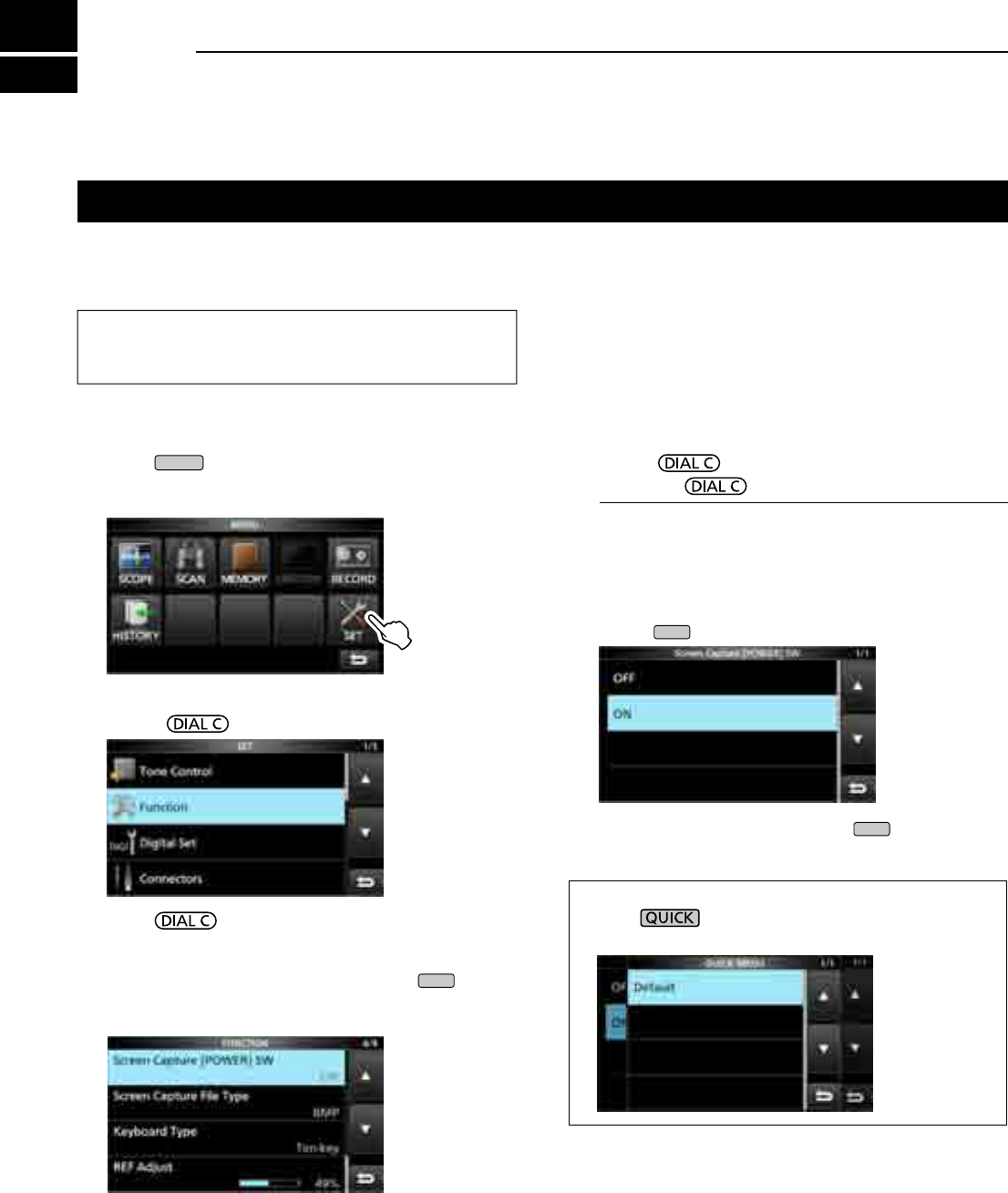
11-1
Set mode description
DEntering the Set mode
1. Push
MENU
.
• Opens the MENU screen.
2. Touch [SET].
3. Rotate to select the desired item.
4. Push to go to the next tree level.
L You can also go to the next tree level by directly
touching the desired item in the screen.
LTo go back the previous tree level, push
EXIT
.
5. Repeat steps 3 and 4 to open the desired item’s
setting screen.
You can use the Set mode to set infrequently changed
values or function settings.
TIP: The Set mode is constructed in a tree structure.
You may go to the next tree level, or go back a level,
depending on the selected item.
6. Rotate to select the desired option, and
then push to set it.
InformationL
• You can also select the option by directly touching the
option or [▲/+] or [▼/–] on the screen.
• To continue setting other items in the same tree level,
repeat step 6.
• To continue setting
other items in a different tree level,
push
EXIT
to go back the previous tree level.
7. To close the SET screen, push
EXIT
several times.
TIP: How to reset to the default setting
Pushing opens the Quick menu, and then touch
“Default” to reset to the default settings.
MENU screen
11 SET MODE
11-2
Tone Control Function
MENU
» SET > Tone Control > FM
HPF/LPF (Default: – – – – – – – – –)
Sets the receive audio high-pass lter and low-pass
lter cutoff frequencies in 100 Hz steps.
Selectable ranges:
• HPF: 100 ~ 2000 Hz
• LPF: 500 ~ 2400 Hz
Bass (Default: 0)
Treble (Default: 0)
Sets the bass or treble level of the receive audio.
• Range: –15 ~ +15
De-Emphasis(50k) (Default: OFF)
De-Emphasis(15k) (Default: ON)
De-Emphasis(7k) (Default: ON)
Turns the de-emphasis circuit ON or OFF for each
bandwidth of lter (50k/15k/7k).
• OFF: The de-emphasis circuit is turned OFF.
• ON: The de-emphasis circuit is turned ON for the
selected band width.
MENU
» SET > Tone Control > WFM
Bass (Default: 0)
Treble (Default: 0)
Sets the bass or treble level of the receive audio.
• Range: –15 ~ +15
MENU
» SET > Tone Control > AM/SSB/CW/FSK/
D-STAR/P25/dPMR/NXDN/DCR
HPF/LPF (Default: – – – – – – – – –)
Sets the receive audio high-pass lter and low-pass
lter cutoff frequencies in 100 Hz steps.
Selectable ranges:
• HPF: 100 ~ 2000 Hz
• LPF: 500 ~ 2400 Hz
Bass (Default: 0)
Treble (Default: 0)
Sets the bass or treble level of the receive audio.
• Range: –15 ~ +15
MENU
» SET > FUNCTION
Beep Level (Default: 50%)
Sets the beep output level.
• Range: 0 ~ 100%
L If the “Beep (Conrmation)” item is set to “OFF,” no beep sounds.
Beep Level Limit (Default: ON)
Selects whether or not to limit the volume up to the
specied level.
• OFF: Does not limit the volume level.
• ON: Limits the volume level.
Further rotation of does not increase
the level.
Beep (Conrmation) (Default: ON)
Turns the Conrmation beep ON or OFF.
• OFF: Does not sound a beep.
• ON: Sounds the beep when a key is pushed.
L If the “Beep Level” item is set to “0%,” no beep sounds.
SPEECH > SPEECH Language (Default: English)
Selects the speech language.
• English: Speech in English.
• Japanese: Speech in Japanese.
SPEECH > SPEECH Speed (Default: Fast)
Selects the speech speed.
• Slow: Speech speed is slow.
• Fast: Speech speed is fast.
SPEECH > S-Level SPEECH (Default: ON)
Turns the S-meter level announcement ON or OFF.
• OFF: When you push , the frequency and
receive mode is announced.
• ON: When you push ,
the S-meter level,
frequency and
receive mode
are announced.
SPEECH > MODE SPEECH (Default: OFF)
Turns the receive mode announcement ON or OFF.
• OFF: The receive mode is not announced.
• ON: The receive mode is announced when you
change the receive mode.
SPEECH > SCAN SPEECH (at Receive Pause)
(Default: OFF)
Turns the frequency announcement ON or OFF.
• OFF: The frequency is not announced.
• ON: When a signal is received during a scan, the
frequency and receive mode is announced.
L If the “S-Level SPEECH” item is set to “On,” S-Meter level
is also announced.
11
SET MODE
1
2
3
4
5
6
7
8
9
10
11
12
13
14
15
16
17
18
19
20
21
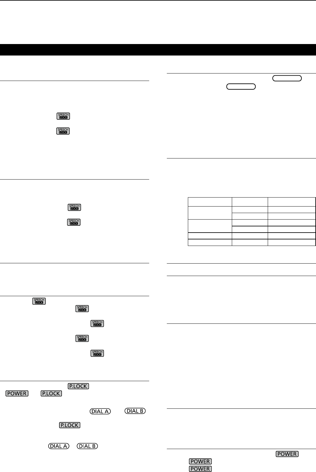
11 SET MODE
11-3
SPEECH > SPEECH Output for Ext connectors
(Default: All)
Selects the announcement condition to output from
the external terminals (USB, LAN, AF/IF and EXT-SP).
• OFF: The announcement is not output.
• Push/Touch: The announcement is output when you
push , or touch the screen.
• All: The announcement is output when you
push or touch the screen, or when
a signal is received during a scan.
L The announcement is not output if [S-Level SPEECH],
[MODE SPEECH] or [SCAN SPEECH] is set to “OFF.”
SPEECH > SPEECH Output for Recording
(Default: All)
Selects the announcement recorded condition.
• OFF: The announcement is not recorded.
• Push/Touch: The announcement is recorded when
you push , or touch the screen.
• All: The announcement is recorded when
you push or touch the screen, or
when a signal is received during a scan.
L The announcement is not recorded if [S-Level SPEECH],
[MODE SPEECH] or [SCAN SPEECH] is set to “OFF.”
SPEECH > SPEECH Level (Default: 50%)
Sets the announcement output level.
• Range: 0 ~ 100%
[SPEECH/LOCK] Switch (Default: SPEECH/LOCK)
Selects the key action.
• SPEECH/LOCK: Pushing turns ON the Speech
function.
Holding down turns the Lock
function ON or OFF.
• LOCK/SPEECH: Pushing turns the Lock
function ON or OFF.
Holding down turns ON the
Speech function.
[P.LOCK] Switch (Default: ALL)
Selects the action of the key.
L and are not locked.
• ALL: All controls are disabled.
• KEY:
All controls except and
are disabled.
L When you hold down for 1 second, the display
backlight is turned OFF.
L
When “KEY” is selected and while the Panel Lock is
activated, rotating or turns ON the display
backlight.
MAIN DIAL Auto TS (Default: High)
Sets the Auto Tuning Step function for
MAIN DIAL
.
When rapidly rotating
MAIN DIAL
, the tuning step
automatically changes according to the rotation speed.
• OFF: Auto tuning step is turned OFF.
• LOW: Approximately 2 times faster.
• HIGH: Approximately 5 times faster when the tuning
step is set to 1 kHz or smaller steps.
Approximately 2 times faster when the tuning
step is set to 5 kHz or larger steps.
AFC Limit (Default: ON)
Selects whether or not to limit the frequency shift
range for the AFC function.
• OFF: Does not limit the frequency shift range.
• ON: Limits the frequency shift range according to
the table below.
Receive mode Filter width AFC range limit
DIGITAL 5 kHz ±3.5 kHz
10 kHz ±7 kHz
FM/DIGITAL 7 kHz ±5 kHz
15 kHz ±10 kHz
FM 50 kHz ±25 kHz
WFM 200 kHz ±100 kHz
[NOTCH] Switch (AM) (Default: Auto/Manual)
[NOTCH] Switch (SSB) (Default: Auto/Manual)
Selects the Notch function type in the SSB or AM mode.
• Auto: Only the Auto notch lter (AN).
• Manual: Only the Manual notch lter (MN).
• Auto/Manual: Both the Auto and Manual notch lters.
SSB/CW Synchronous Tuning (Default: OFF)
Turns the Displayed Frequency Shift function ON or OFF.
This function automatically shifts the frequency to
match the CW pitch when the operating mode is
toggled between SSB and CW.
• OFF:
Stays on the frequency even when the operating
mode is toggled between SSB and CW.
• ON: Shifts the frequency when the operating mode
is
toggled
between SSB and CW, to keep
receiving the signal.
CW Normal Side (Default: LSB)
Selects the carrier point in the CW normal mode.
• LSB: The LSB side.
• USB: The USB side.
Screen Capture [POWER] Switch (Default: OFF)
Assigns the Screen Capture function to .
• OFF:
does not act as the Screen Capture key.
• ON: acts as the Screen Capture key.
Function (Continued)
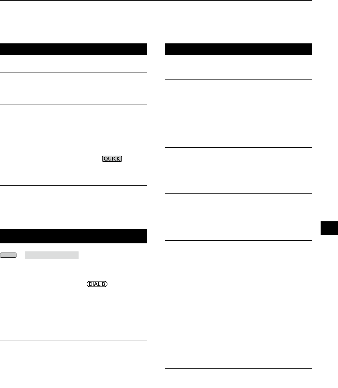
11-4
Function (Continued) Digital Set (Continued)
Screen Capture File Type (Default: PNG)
Selects the le format for the Screen Capture function.
• Options: PNG or BMP
Keyboard Type (Default: Full Keyboard)
Sets the keyboard entry type to Ten-key or Full
Keyboard.
• Ten-key: Ten-key type
• Full Keyboard: Full Keyboard type
L You can enter upper case letters, lower
case letters, numbers, some symbols
and spaces with this type.
L When the edit screen is displayed, push to open
the QUICK menu and select the desired keyboard type.
REF Adjust
Calibrates the internal reference frequency (10 MHz).
• Range: 0 ~ 100%
Digital Set
MENU
» SET > Digital Set
Digital Monitor (Default: Auto)
Selects the receive mode when is pushed in
the DIGITAL mode.
• Auto: Receives in the DIGITAL mode or the FM
mode, depending on the received signal.
• Digital: Receives in the DIGITAL mode.
• Analog: Receives in the FM mode.
Digital Mode Select (Default: (All modes selected))
Selects the DIGITAL mode options. Only checked modes
are displayed as the option on the [MODE] screen.
• Options: D-STAR, P25, dPMR, NXDN-n, NXDN-vn
and DCR
RX History Log > RX History Log (Default: OFF)
You can store the Received Call logs on to an SD card
in CSV format.
• OFF: Does not store the log.
• ON: Stores the logs.
RX History Log > CSV Format > Separator/Decimal
(Default: Sep [,] Dec [.])
Selects the separator and the decimal character for
the CSV format.
• Sep [,] Dec [.]: Separator is “,” and Decimal is “.”
• Sep [;] Dec [.]: Separator is “;” and Decimal is “.”
• Sep [;] Dec [,]: Separator is “;” and Decimal is “,”
L The default value differs, depending on the receiver
version.
RX History Log > Date > Date (Default: yyyy/mm/dd)
Selects the date format between “yyyy/mm/dd,” “mm/
dd/yyyy” and “dd/mm/yyyy.” (y: year, m: month, d: day)
L* The default value may differ, depending on the receiver
version.
D-STAR Standby Beep (Default: ON)
Turns the Standby Beep function ON or OFF.
• OFF: Turns OFF the function.
• ON: Sounds a beep after a received signal
disappears, in the DV (D-STAR) mode.
D-STAR Auto Detect (Default: OFF)
Turns the DV (D-STAR) mode Automatic Detect
function ON or OFF.
• OFF: Turns OFF the function. The receive mode is
xed to the DV mode.
• ON: Automatically and temporarily switches to the
FM mode, when an FM signal is received in
the DV mode.
RX Record (D-STAR RPT) (Default: All)
Records the received call history when a DV (D-STAR)
signal is received.
• ALL: Records up to 50 calls.
• Latest Only: Records only the last call.
D-STAR EMR AF Level (Default: 20%)
Set the audio output level for when an EMR (Enhanced
Monitor Request) communication signal is received in
the DV (D-STAR) mode.
Range: 0 ~ 100%
L When an EMR signal is received, the audio will be heard at
the set level, or the [AF GAIN] level, whichever is higher.
LTo disable the setting, set it to “0%.”
11
SET MODE
1
2
3
4
5
6
7
8
9
10
11
12
13
14
15
16
17
18
19
20
21

11 SET MODE
11-5
Connectors
Phones Level Ratio (Default: 1.00)
Sets the output ratio of the speaker output level and
headphones output level.
• Range: 0.40 ~ 2.00
AF/IF > Output Select (Default: AF)
Selects the signal output from [AF/IF].
• AF: The demodulated AF signal is output.
• IF: A 12 kHz IF signal is output.
L You can listen to the Digital Radio Mondiale (DRM)
broadcast with an application software receiver if it
is installed into your PC.
AF/IF > AF Output Level (Default: 50%)
Sets the AF output level of [AF/IF].
• Range: 0 ~ 100%
L At 50% (default), the output level is 200 mV (RMS).
AF/IF > AF SQL (Default: OFF (OPEN))
Selects whether or not to output the audio from [AF/IF],
according to the squelch and signal levels.
• OFF(OPEN):
The squelch is always opened regardless
of the squelch and signal levels.
• ON:
The squelch opens and closes, according
to the squelch and signal levels.
AF/IF > AF Beep/Speech... Output (Default: OFF)
Sets the Beep and Speech audio output status of [AF/IF]
.
• OFF: The beep and speech audio are not output
from [AF/IF].
• ON: The beep and speech audio are output from
[AF/IF].
AF/IF > IF Output Level (Default: 50%)
Sets the IF output level of [AF/IF].
• Range: 0 ~ 100%
L At 50% (default), the output level is 200 mV (RMS).
USB (Front) > Output Select (Default: AF)
Selects the signal output from [USB] on the front panel.
• AF: The demodulated AF signal is output.
• IF: A 12 kHz IF signal is output.
L You can listen to the Digital Radio Mondiale (DRM)
broadcast with the application software receiver that
is installed into your PC.
USB (Front) > AF Output Level (Default: 50%)
Sets the AF output level of [USB] on the front panel.
• Range: 0 ~ 100%
MENU
» SET > Connectors USB (Front) > AF SQL (Default: OFF (OPEN))
Selects whether or not to output the audio from [USB] on
the front panel, according to the squelch and signal levels.
• OFF(OPEN):
The squelch is always opened regardless
of the squelch and signal levels.
• ON:
The squelch opens and closes, according
to the squelch and signal levels.
USB (Front) > AF Beep/Speech... Output
(Default: OFF)
Sets the Beep and Speech audio output status of
[USB] on the front panel.
• OFF: The beep and speech audio are not output
from [USB] on the front panel.
• ON: The beep and speech audio are output from
[USB] on the front panel.
USB (Front) > IF Output Level (Default: 50%)
Sets the IF (12 kHz) output level of [USB] on the front
panel.
• Range: 0 ~ 100%
USB (Front) > Serial Function (Default: FSK Decode)
Selects the signal output from [USB] on the front panel.
• FSK Decode: An FSK decoded signal is output.
• D-STAR Data: A D-STAR data is output.
USB (Front) > FSK Decode Baud Rate (Default: 9600)
Selects the data transfer rate (Baud rate) of decoded
FSK signals from [USB] on the front panel.
• Options: 4800, 9600, 19200 or 38400 (bps)
USB (Front) > D-STAR Data Baud Rate (Default: 9600)
Selects the data transfer rate (Baud rate) of decoded
D-STAR data
from [USB] on the front panel.
• Options: 4800 or 9600 (bps)
USB (Rear) > Output Select (Default: AF)
Selects the signal output from [USB] on the rear panel.
• AF: The demodulated AF signal is output.
• IF: A 12 kHz IF signal is output.
L You can listen to the Digital Radio Mondiale (DRM)
broadcast with the application software receiver that
is installed into your PC.
USB (Rear) > AF Output Level (Default: 50%)
Sets the AF output level of [USB] on the rear panel.
• Range: 0 ~ 100%
L At 50% (default), the output level is 200 mV (RMS).

11-6
Connectors (Continued)
USB (Rear) > AF SQL (Default: OFF (OPEN))
Selects whether or not to output the audio from [USB] on
the rear panel, according to the squelch and signal levels.
• OFF(OPEN):
The squelch is always opened regardless
of the squelch and signal levels.
• ON:
The squelch opens and closes, according
to the squelch and signal levels.
USB (Rear) > AF Beep/Speech... Output
(Default: OFF)
Sets the Beep and Speech audio output status of
[USB] on the rear panel.
• OFF: The beep and speech audio are not output
from [USB] on the rear panel.
• ON: The beep and speech audio are output from
[USB] on the rear panel.
USB (Rear) > IF Output Level (Default: 50%)
Sets the IF (12 kHz) output level of [USB] on the rear panel.
• Range: 0 ~ 100%
USB (Rear) > Serial Function (Default: FSK Decode)
Selects the signal output from [USB] on the rear panel.
• FSK Decode: An FSK decoded signal is output.
• D-STAR Data: A D-STAR data is output.
USB (Rear) > FSK Decode Baud Rate (Default: 9600)
Selects the data transfer rate (Baud rate) of decoded
FSK signals from [USB] on the rear panel.
• Options: 4800, 9600, 19200 or 38400 (bps)
USB (Rear) > D-STAR Data Baud Rate (Default: 9600)
Selects the data transfer rate (Baud rate) of decoded
D-STAR data
from [USB] on the rear panel.
• Options: 4800 and 9600 (bps)
LAN > Output Select (Default: AF)
Selects the signal output from [LAN].
• AF: The demodulated AF signal is output.
• IF: A 12 kHz IF signal is output.
L You can listen to the Digital Radio Mondiale (DRM)
broadcast with an application software receiver that
is installed into your PC.
LAN > AF SQL (Default: OFF (OPEN))
Selects whether or not to output the audio from [LAN],
according to the squelch and signal levels.
• OFF(OPEN):
The squelch is always opened regardless
of the squelch and signal levels.
• ON:
The squelch opens and closes, according
to the squelch and signal levels.
LAN > AF Speech Output (Default: OFF)
Sets the Speech audio output status of [LAN].
• OFF: The speech audio is not output from [LAN].
• ON: The speech audio is output from [LAN].
L You should set the “AF SQL” item to “AF.”
CI-V > CI-V Baud Rate (Default: Auto)
Selects the CI-V data transfer rate.
• Options: 4800, 9600, 19200 (bps) or Auto
L When “Auto” is selected, the baud rate is automatically set,
according to the data rate of the connected controller.
CI-V > CI-V Address (Default: 96h)
Selects the CI-V address.
• Range: 02h ~ 96h ~ DFh
L“96h” is the default address of the IC-R8600.
CI-V > CI-V Transceive (Default: ON)
Turns the Transceive function ON or OFF.
• OFF: The status is not output.
• ON: The status is output.
CI-V >
USB/LAN→REMOTE Transceive Address
(Default: 00h)
Sets the address used to remotely control the receiver
using the optional RS-R8600 (future product), through
the [USB] or [LAN] port.
The external equipment control signal is output from
the [REMOTE] port.
• Range: 00h ~ DFh
CI-V > CI-V USB (Front) Baud Rate (Default: Auto)
Selects the CI-V data transfer rate for [USB] on the
front panel.
• Options: 4800, 9600, 19200, 38400, 57600, 115200
(bps) or Auto
L When “Auto” is selected, the baud rate is automatically set
according to the data rate of the connected controller.
CI-V > CI-V USB (Front) Echo Back (Default: OFF)
Turns the Data Echo Back function ON or OFF, when
remotely controlling through the [USB] CI-V port.
• OFF: Turns OFF the function.
• ON: Turns ON the function.
TIP: When multiple devices are connected.
The default transceive address is “00h.” To control
dedicated equipment when several devices are
connected, set the same CI-V address.
11
SET MODE
1
2
3
4
5
6
7
8
9
10
11
12
13
14
15
16
17
18
19
20
21
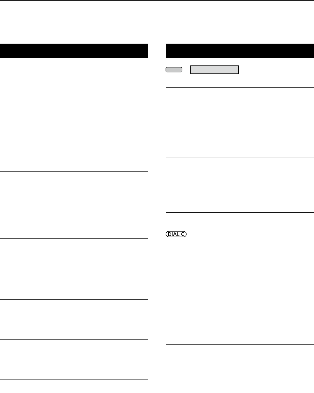
11 SET MODE
11-7
Connectors (Continued)
CI-V > CI-V USB (Rear) Port
(Default: Unlink from [REMOTE])
Selects the internal connection type between the [USB]
port on the rear panel and the [REMOTE] CI-V port.
• Link to [REMOTE]:
The [USB] port on the rear panel and the
[REMOTE] CI-V port are internally connected.
• Unlink from [REMOTE]:
The [USB] port on the rear panel and [REMOTE]
CI-V port are not internally connected.
Each port functions independently.
(duplex communication can be made.)
CI-V > CI-V USB (Rear) Baud Rate (Default: Auto)
Selects the CI-V data transfer rate (bps) for [USB] on
the rear panel.
• Options:
4800, 9600, 19200, 38400, 57600, 115200 or Auto
L When “Auto” is selected, the baud rate is automatically set
according to the data rate of the connected controller.
L This setting is valid only when the “CI-V USB Port” item is
set to “Unlink from [REMOTE].”
CI-V > CI-V USB (Rear) Echo Back (Default: OFF)
Turns the Data Echo Back function ON or OFF, when
remotely controlling through the [USB] CI-V port.
• OFF: Turns OFF the function.
• ON: Turns ON the function.
L This setting is .valid only when the “CI-V USB Port” item is
set to “Unlink from [REMOTE].”
External Meter Output (Default: Signal)
Selects the signal output from [METER].
• Signal: Signal strength.
• Signal+SQL: Signal strength and squelch level.
External Meter Level (Default: 50%)
Sets the voltage level output from [METER].
• Range: 0 ~ 100%
L 8 V DC is output at full scale (50%). (into a 10 kΩ load)
REF IN/OUT (Default: OFF)
Selects the receiver’s reference frequency signal source.
• IN: Uses an external reference signal.
NOTE: SELECT “OFF” or “OUT” if you are
not use a reliable external signal source.
When the input signal source level is too low,
or the frequency precision is not high, the fre-
quency readout blinks and the receiver does
not function correctly.
• OFF: Does not input/output the reference signal.
• OUT: Outputs the internal reference signal.
Network
DHCP (Valid after Restart) (Default: ON)
Turns the DHCP function ON or OFF.
• OFF: Uses the static IP address.
• ON: Uses the DHCP function.
If a DHCP server is in your network environ-
ment, the IP address is automatically obtained.
LThis setting takes effect after restart.
IP Address (Valid after Restart)
(Default: 192.168. 0. 10)
Sets the static IP address.
L This setting is valid when “OFF” is selected the [DHCP
(Valid after Restart)] item.
LThis setting takes effect after restart.
Subnet Mask (Valid after Restart)
(Default: 255.255.255.0 (24bit))
Sets the subnet mask to connect to your PC or LAN
(Local Area Network), through the Ethernet. Rotate
to set.
• Range: 128.0.0.0 (1 bit) ~ 255.255.255.252 (30 bit)
LThis setting takes effect after restart.
Default Gateway (Valid after Restart)
(Default: . . . )
When you remotely control the IC-R8600 using the
optional RS-R8600 (future product), a default gateway
setting is required.
L This setting is valid when “OFF” is selected the [DHCP
(Valid after Restart)] item.
LThis setting takes effect after restart.
Primary DNS Server (Valid after Restart)
(Default: . . . )
If there are two DNS server addresses, enter the pri-
mary DNS server address.
LThis setting takes effect after restart.
2nd DNS Server (Valid after Restart)
(Default: . . . )
If there are two DNS server addresses, enter the sec-
ondary DNS server address.
LThis setting takes effect after restart.
MENU
» SET > Network
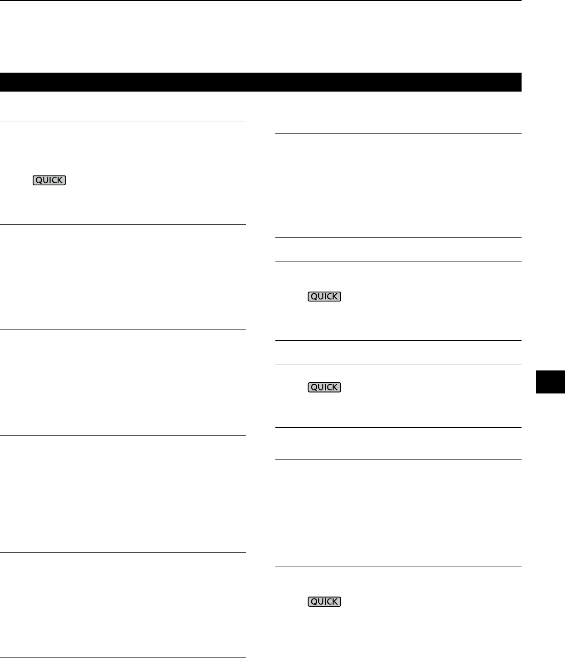
11-8
Network Name
When you remotely control the IC-R8600 using the
optional RS-R8600 (future product), enter a network
name.
L“.” (period) cannot be used for the rst character.
LPush to change the keyboard type.
LRefer to page 1-7 for the character entering.
Network Control (Valid after Restart) (Default: OFF)
When you remotely control the IC-R8600 using the op-
tional RS-R8600 (future product), select “ON.”
• OFF: Turn OFF the function.
• ON: Turn ON the function.
LThis setting takes effect after restart.
Power OFF Setting (for Remote Control)
(Default: Shutdown only)
When you remotely control the IC-R8600 using the op-
tional RS-R8600 (future product), select “ON.”
• Shutdown only: Shuts down immediately.
• Standby/Shutdown: Displays the SHUTDOWN dia-
log before shutting down.
Control Port (UDP) (Valid after Restart)
(Default: 50001)
When you remotely control the IC-R8600 using the op-
tional RS-R8600 (future product), set a port number for
the control signal transfers between the IC-R8600 and
the remote station.
• Set the same port number to the PC.
LThis setting takes effect after restart.
Serial Port (UDP) (Valid after Restart)
(Default: 50002)
When you remotely control the IC-R8600 using the op-
tional RS-R8600 (future product), set a port number for
the serial data transfers between the IC-R8600 and the
remote station.
LThis setting takes effect after restart.
Audio Port (UDP) (Valid after Restart)
(Default: 50003)
When you remotely control the IC-R8600 using the op-
tional RS-R8600 (future product), set a port number for
the audio signal transfers between the IC-R8600 and
the remote station.
LThis setting takes effect after restart.
Network (Continued)
Internet Access Line (Valid after
Restart
)
(Default: FTTH)
When you remotely control the IC-R8600 using the op-
tional RS-R8600 (future product), set the port number
for the audio signal transfers between the IC-R8600
and the remote station.
• Set the same port number to the remote station.
LThis setting takes effect after restart.
Network user1 > Network User1 ID
Network user2 > Network User2 ID
When you remotely control the IC-R8600 using the op-
tional RS-R8600 (future product), enter a user name.
LPush to change the keyboard type.
LRefer to page 1-7 for the character entering.
Network user1 > Network User1 Password
Network user2 > Network User2 Password
Enter a password for each user.
LPush to change the keyboard type.
LRefer to page 1-7 for the character entering.
Network user1 > Network User1 Administrator
Network user2 > Network User2 Administrator
(Default: NO)
Sets the user as the administrator.
Only authorized users can disconnect the communi-
cation between the remote IC-R8600 and the optional
RS-R8600 (future product).
• NO: Not authorized.
• YES: Authorized.
Network Radio Name (Default: IC-R8600)
When you remotely control the IC-R8600 using the op-
tional RS-R8600 (future product), enter a nickname.
LPush to change the keyboard type.
LRefer to page 1-7 for the character entering.
11
SET MODE
1
2
3
4
5
6
7
8
9
10
11
12
13
14
15
16
17
18
19
20
21
11 SET MODE
11-9
Display
LCD Backlight (Default: 50%)
Sets the LCD backlight brightness.
• Range: 0 (dark) ~ 100% (bright)
LED Bright (Default: 80%)
Sets the LED brightness.
• Range: 0 (dark) ~ 100% (bright)
Display Type (Default: A)
Sets the display background type to A or B.
• A: Display background color is black.
• B: Display background color is blue.
Meter Peak Hold (Default: ON)
Turns the Meter Peak Hold function ON or OFF.
• OFF: Does not hold the peak level.
• ON: Holds the peak level on the signal meter
display for 0.5 seconds.
Memory Name (Default: ON)
Turns the Memory name display in the Memory mode
ON or OFF.
• OFF: Memory name is not displayed, even if entered.
• ON: The entered Memory name is displayed
above the frequency display.
Group Name Popup (Default: ON)
Select whether or not to display the group name when
you change the memory channel group.
• OFF: The group name is not displayed.
• ON: The group name is displayed.
MN-Q Popup (MN OFF→ON) (Default: ON)
Selects whether or not to display the Manual Notch
lter width when you select the Manual Notch.
• OFF: The Manual Notch lter width is not displayed.
• ON: The Manual Notch lter width is displayed.
BW Popup (PBT) (Default: ON)
Selects whether or not to display the digital TWIN PBT
shift value while rotating
TWIN PBT
CLR
.
• OFF: The the PBT and center shift value are not
displayed.
• ON:
The the PBT and center shift value are displayed.
BW Popup (FIL) (Default: ON)
Selects whether or not to display the digital IF lter
width and shift value when you change the IF lter.
• OFF:
The IF lter width and shift value are not displayed.
• ON:
The IF lter width and shift value are displayed.
MENU
» SET > Display RX Popup (Default: Normal)
Selects whether or not to display the information included
in the received digital signal such as call sign, caller’s ID,
code and so on, when you receive a digital signal.
• OFF: The information is not displayed.
• Normal: The information is displayed for
approximately 3 seconds.
• RX Hold: The information is displayed until an
operation is performed.
• Hold:
The information is displayed and remains,
even an operation is performed.
P25 RX ID Display (Default: Dec)
Selects the P25 Talk-group ID display type.
• Dec: In Decimal.
• Hex:
In Hexadecimal.
Screen Saver (Default: 60min)
Sets the Screen Saver function.
This function activates and automatically turns OFF
the screen* when no operation is performed for the
preset period of time.
• OFF: Turns OFF the function.
• 15min: Activates after 15 minutes with no operation.
• 30min: Activates after 30 minutes with no operation.
• 60min: Activates after 60 minutes with no operation.
* indicator blinks.
Opening Message (Default: ON)
Selects whether or not to display the opening message
(including the opening comment) at power ON.
• OFF: Opening message is not displayed.
• ON: Opening message is displayed.
Opening Comment
Enter the opening comment displayed with the
opening message at power ON.
LPush to change the keyboard type.
LRefer to page 1-7 for the character entering.
Display Language (Default: English)
Sets the display language.
• English: Displays in English.
• Japanese: Displays in Japanese.
L This item is not displayed when “English” is selected in
the “System Language” item.
System Language (Default: English)
Sets the system language.
• English: Displays in English.
• Japanese: Displays in Japanese.
L
If you set the language to English, all Japanese characters
(such as memory name) you entered are garbled. But the
display returns to normal when you change to Japanese again.
11-10
Time Set
Date/Time > Date (Default: 2000/01/01)
Sets the date* (Year/Month/Day).
• Settable range: 2000/01/01 ~ 2099/12/31
LThe day of the week is automatically set.
L If the NTP Function is ON and receiver is connected to
Internet, these items are automatically set.
Date/Time > Time (Default: 0:00)
Sets the current time.
• Settable range: 0:00 ~ 23:59
LThe time is displayed in the 24 hour format.
L If the NTP Function is ON and receiver is connected to
Internet, these items are automatically set.
Date/Time > <<NTP TIME SYNC>>
Touch to synchronize the internal clock to the NTP server.
• Automatically obtains the current time from the NTP server.
Date/Time > NTP Function (Default: ON)
Automatically obtains the current time from the NTP server.
• OFF: Turn OFF the function.
• ON: Use the function. (An internet access is necessary.)
Date/Time
> NTP Server Address
(Default: time.nist.gov)
Sets the NTP server address.
LDo not change this setting, unless it is necessary.
LRefer to page 1-7 for the character entering.
UTC Offset (Default: + 0:00)
Sets the UTC offset time.
• Range: –14:00 to +14:00 (in 5 minute steps)
SD Card
Load Setting
Selects the saved data le to load.
L See “Using An SD Card” in Section 7 for data load details.
Save Setting
Saves the setting data onto an SD card.
L See “Using An SD Card” in Section 7 for data write details.
SD Card Info
Displays the SD card capacity and the time remaining
for recording.
Screen Capture View
Displays the selected screen capture.
L See “Screen Capture function” (p. 5-11) for details.
Firmware Update
Enters the Firmware Update mode.
L See “Updating the rmware” (p. 13-1) for details.
Format
Formats the SD card.
L See “Formatting an SD card” (p. 7-2) for details.
Unmount
Unmounts the SD card.
SD Card (Continued)
Others
Information > Version
Displays the rmware version.
Clone > Clone Mode
Touch to enter the cloning mode.
L The cloning mode is cancelled on restart.
Touch Screen Calibration
Touch to adjust the touch screen.
L
Touch the white dots that sequentially appears on the screen.
<<BER Measurement Start/Stop>>
Touch to enter or quit the BER Measurement mode.
• “BER” is displayed while in the measurement mode.
•
Push to select the testing signal type (Clock/Data or
UART) and measurement mode (General or P25 specic).
Reset > Partial Reset
Touch to return all the settings to their factory defaults
except the memory channels.
L See “Resetting” (p. 12-2) for details.
Reset > All Reset
Touch to return all the settings to their factory defaults,
and clears all the memory channels.
L See “Resetting” (p. 12-2) for details.
MENU
» SET > Time Set
MENU
» SET > Time Set
NOTE:
Before you remove a card when the receiver is ON,
be sure to electrically unmount it (p. 7-1). Otherwise
the data may be corrupted or deleted.
MENU
» SET > Other
11
SET MODE
1
2
3
4
5
6
7
8
9
10
11
12
13
14
15
16
17
18
19
20
21
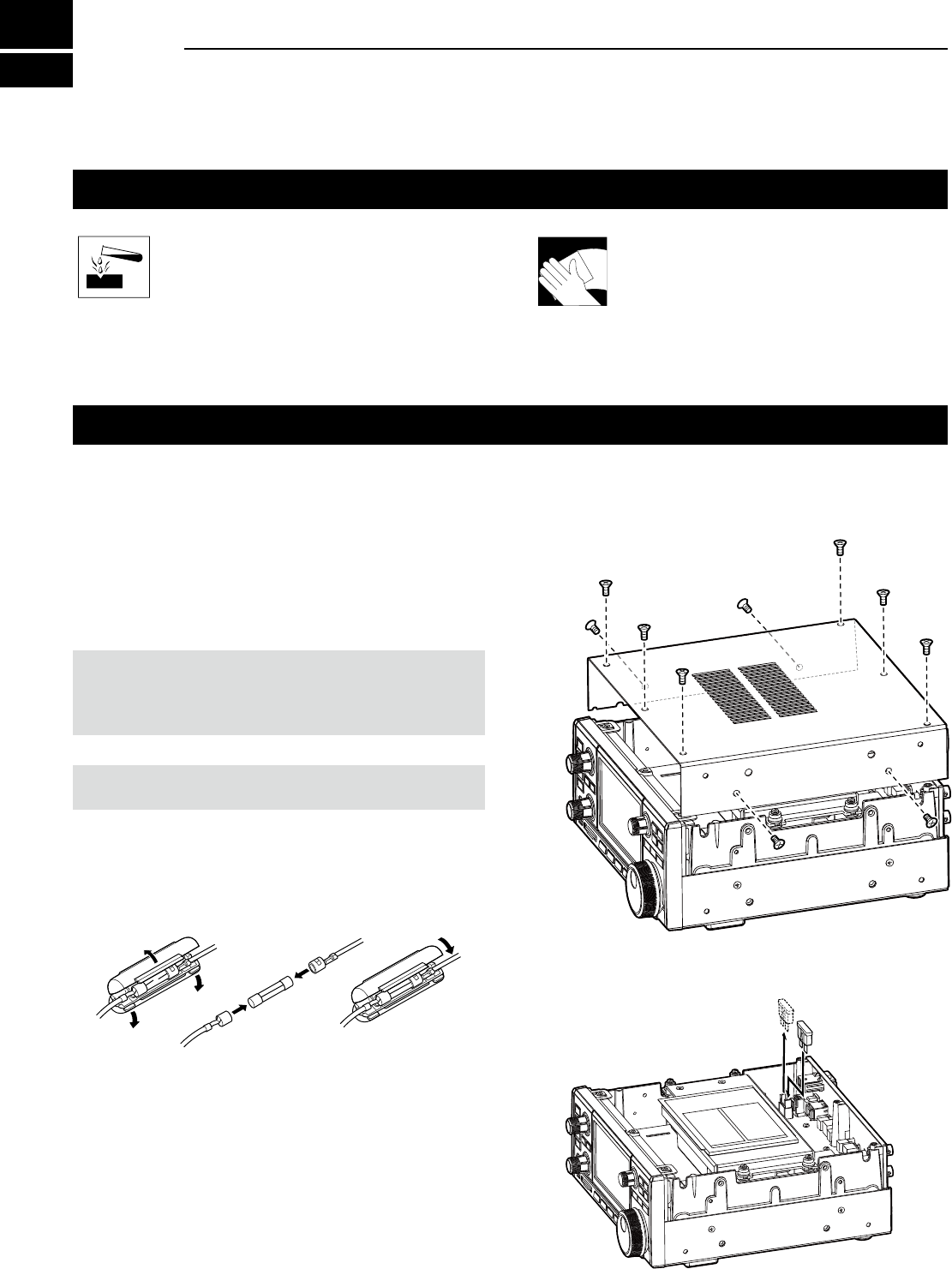
12-1
Cleaning
DO NOT use harsh solvents such as
benzine or alcohol when cleaning,
because they will damage the receiver
surfaces.
If the receiver becomes dusty or dirty,
wipe it clean with a dry, soft cloth.
Replacing fuse
If a fuse blows, or the receiver stops functioning, nd
and repair the cause of the problem. Then replace the
damaged fuse with a new, adequately rated fuse.
The fuses are installed in the DC power cable and the
circuitry in the body, to protect the receiver.
• DC power cable fuses .................................3 A/125 V
• Circuitry fuse .........................................ATC 3 A/32 V
RWARNING!
• Disconnect the DC power cable from the receiver before
replacing the fuse.
• NEVER use fuses that are not specied.
CAUTION: When you remove a fuse, use longnose pliers
to protect your ngers and the fuse holders.
DDC power cable fuses
See the following illustration to replace the blown DC
power cable fuse.
DCircuitry fuse
1. Remove the 10 screws, then remove the cover.
2. Replace the circuitry fuse as shown below.
3. Replace the cover and the screws.
ATC 3 A fuse
3 A fuses
12 MAINTENANCE
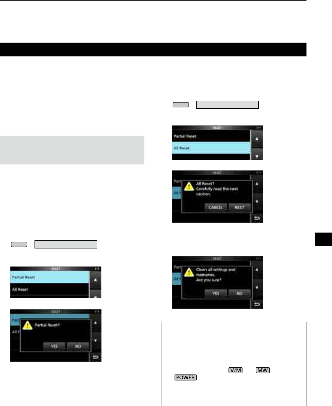
12-2
Resetting
Occasionally, erroneous information may be
displayed. This may be caused by static electricity or
by other factors.
If this problem occurs, turn OFF the receiver. After
waiting a few seconds, turn ON the receiver.
If the problem still exists, perform a Partial reset as
described below.
If the problem still exists after a Partial reset, perform
an All reset as described to the right.
NOTE: An All reset clears all data and returns all settings
to their factory defaults. Save memory channel content,
setting status, and so on, onto an SD card before doing an
All reset. (p. 7-2)
DPartial reset
A Partial reset resets operating settings to their default
values (Timer setting, NTP Server Address, Lower and
upper edge of the spectrum scope, Set mode items).
L Network settings, Reference frequency, Memory channels
and Opening comments are not returned to their default
value.
1. Open the RESET screen.
MENU
» SET > Others > Reset
2. Touch “Partial reset.”
• The conrmation screen is displayed.
3. Touch [Yes].
L After resetting, the IC-R8600 will automatically
restart.
DAll reset
All reset clears all data and returns all settings to their
factory defaults.
1. Open the RESET screen.
MENU
» SET > Others > Reset
2. Touch “All reset.”
• The conrmation screen is displayed.
3. Touch [NEXT].
4. After carefully reading the displayed message,
touch [YES] to perform the All reset.
L After resetting, the IC-R8600 will automatically
restart.
TIP: When you cannot operate the screen
If a touch screen operation error or an unexpected
operation occurs, you cannot enter the Set mode. In
that case, perform the All reset as described below:
1. Turn OFF the receiver power.
2. While holding down and , push
.
• "ALL RESET" is displayed on the opening screen.
L If "ALL RESET" is not displayed, repeat the above
procedure again.
12
MAINTENANCE
1
2
3
4
5
6
7
8
9
10
11
12
13
14
15
16
17
18
19
20
21
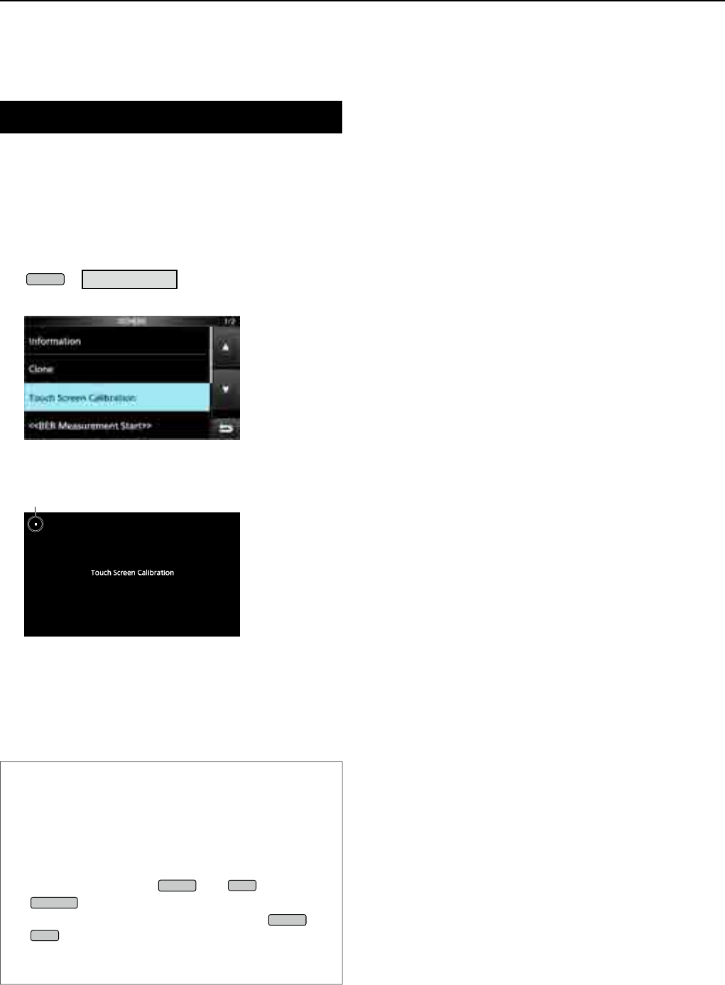
12-3
MAINTENANCE
12
Touch screen calibration
When no screen action occurs, or a different function
is activated after touching the screen, the touched
point and the detected point may be different.
In that case, the Touch screen calibration function
helps to correct the touch screen sensing accuracy.
1. Open the OTHERS screen.
MENU
» SET > Others
2. Touch “Touch Screen Calibration.”
• A dot appears on the screen.
3. Touch the dot that appears on the screen.
• A new dot appears in another position.
4. Repeat step 3.
L When the calibration is complete, the receiver returns
to the OTHERS screen.
5. Touch the frequency readout or key on the screen,
to check the sensing accuracy was corrected.
TIP: When the touch screen is not accurate, and
you cannot access the OTHERS screen.
Do the following steps to correct the touch screen
sensing accuracy.
1. Turn OFF the receiver power.
2. While holding down
MENU
and
EXIT
, push
POWER
to display the “Touch Window
Calibration” screen, and then release
MENU
and
EXIT
.
3. Repeat the above touch screen calibration
procedure.
dot
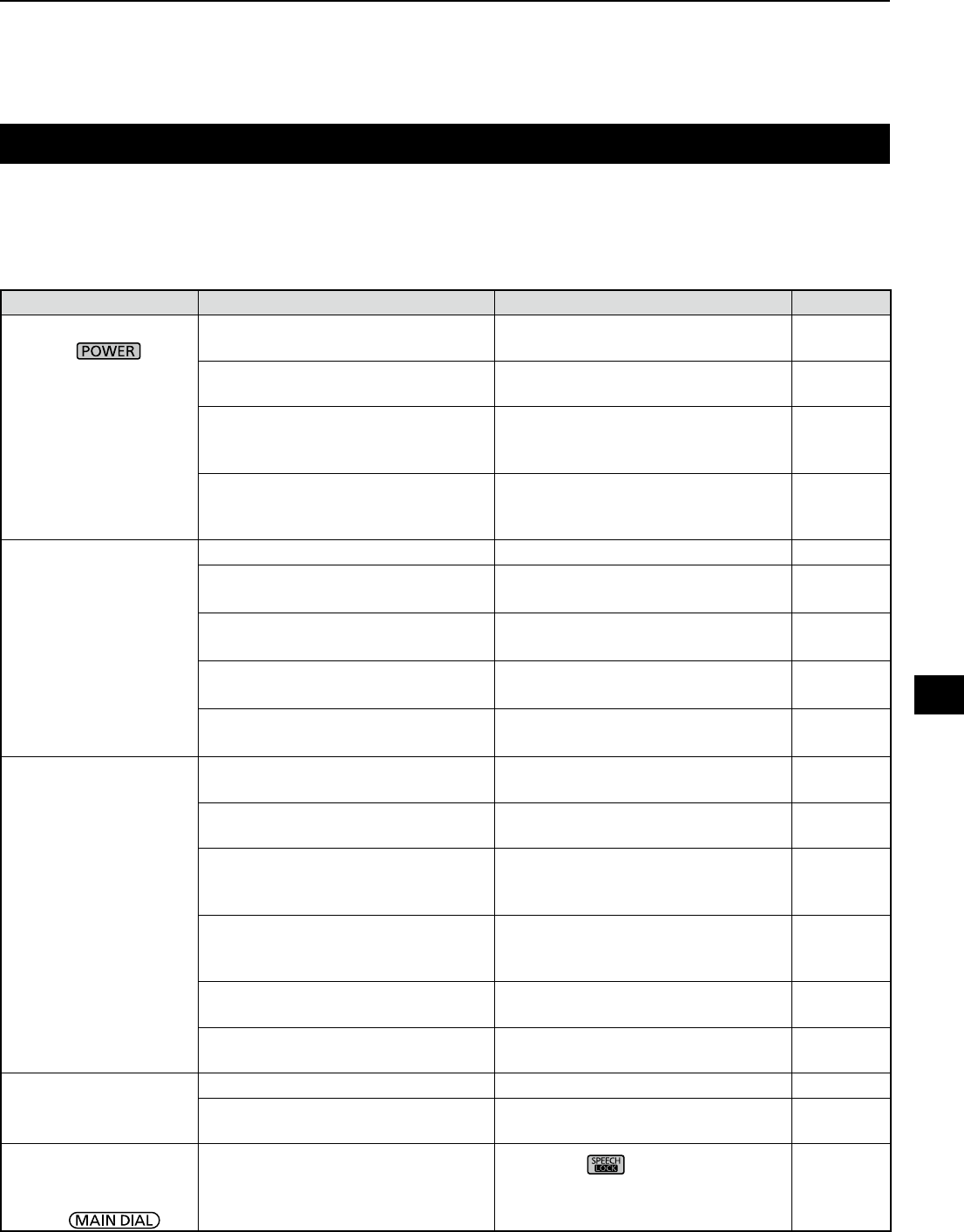
12-4
Troubleshooting
The following chart is designed to help you correct problems which are not equipment malfunctions.
If you are unable to locate the cause of a problem, or solve it through the use of this chart, contact your nearest
Icom Dealer or Service Center.
PROBLEM POSSIBLE CAUSE SOLUTION REF.
Power does not come
on when is
pushed.
Power cable is improperly
connected. Reconnect the power cable correctly. p. 2-1
The external power supply is turned
OFF. Turn ON the external power supply. p. 2-1
The DC power cable fuses or
circuitry fuse is blown. Find and repair the cause of the
problem and then replace the
damaged fuse with a new one.
p. 12-1
The optional AD-55NS or SP-39AD
is used but the supplied short
connector is not connected.
Connect the supplied DC power
short connector to [DC 13.8 V]. p. 2-1
No sound is heard from
the speaker. Audio level is too low or 0%. Set the audio level to a higher level. p. 3-1
The squelch is too tight. Set the squelch level to open the
squelch. p. 3-1
The Tone/Code squelch or Digital
squelch (D.SQL) is ON. Turn OFF the Tone or Digital
squelch. p. 5-9
A headphones is connected to [EX-
SP] or [PHONES]. Disconnect the headphones. p. 2-3
The external speaker cable is
disconnected. Check the external speaker cable
and repair it. p. 2-3
Sensitivity is too low,
and only strong signals
can be heard.
The attenuator is activated. Turn OFF the attenuator in the
FUNCTION screen. p. 5-1
The RF gain is reduced. ("RFG" is
displayed.) Set [RF GAIN] to 100%. ("RFG" is
disappeared.) p. 3-1
The antenna is defective or
the coaxial cable is shorted or
disconnected.
Repair the problem and then
reconnect to the antenna connector. p. 2-2
You are using an antenna not
suitable for the band you have
selected.
Connect an antenna suitable for the
operating frequency. p. 2-2
The selected antenna connector is
incorrect. Select the appropriate antenna
connector. pp. 2-2, 3-2
or 5-1
The squelch is too tight. Set the squelch level to open the
squelch. p. 3-1
Received audio in the
SSB mode is unclear or
distorted.
The incorrect sideband is selected. Toggle between USB and LSB. p. 3-1
The Digital TWIN PBT function is
activated. Touch [PBT1] or [PBT2] for 1 second
to clear the settings. p. 5-2
The displayed
frequency does not
properly change by
rotating .
The Dial Lock function is activated.
(The [LOCK] indicator lights.) Hold down for 1 second to turn
OFF the Lock function.
p. 3-3
12
MAINTENANCE
1
2
3
4
5
6
7
8
9
10
11
12
13
14
15
16
17
18
19
20
21
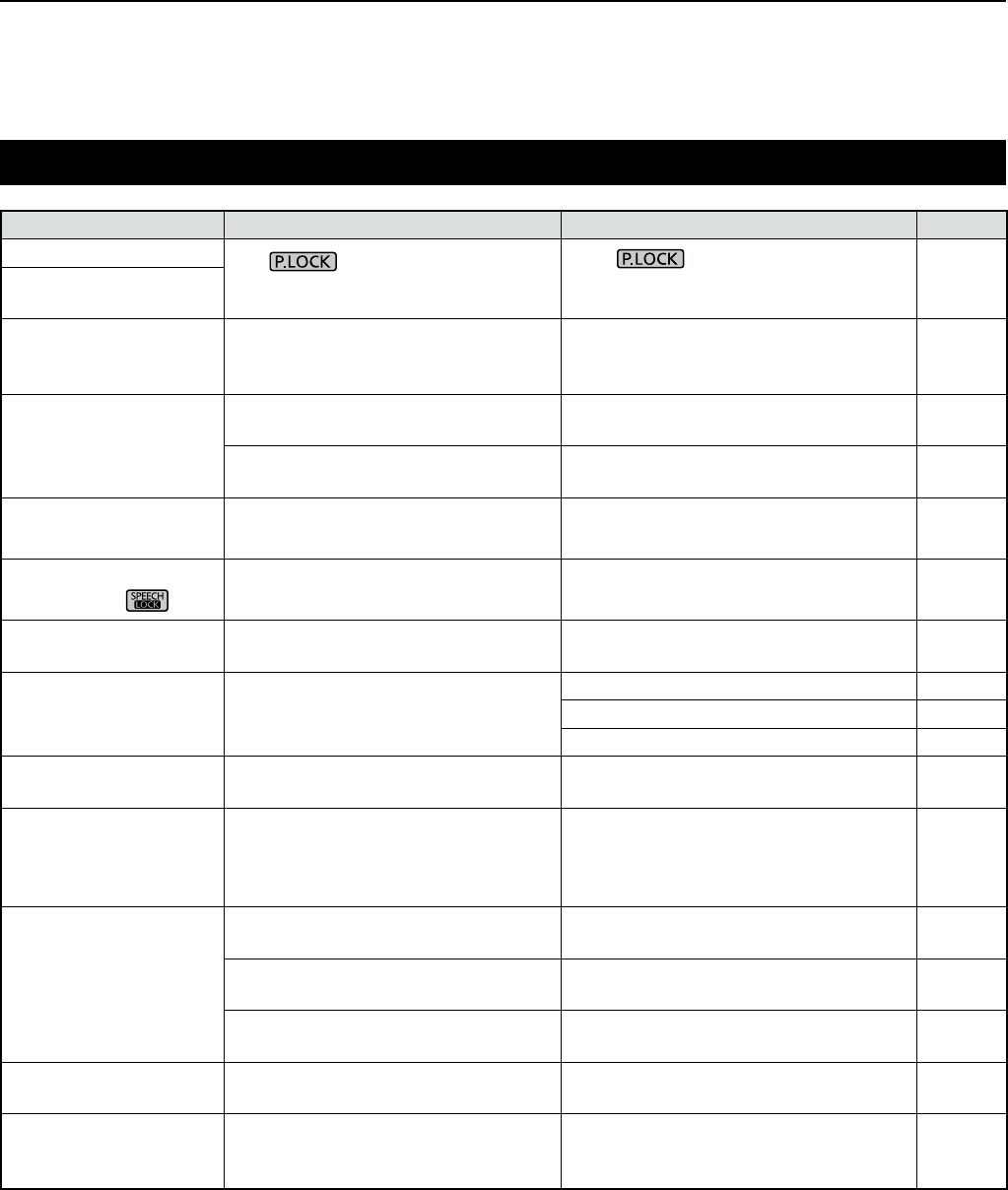
12-5
MAINTENANCE
12
Troubleshooting (Continued)
PROBLEM POSSIBLE CAUSE SOLUTION REF.
The backlight is OFF. The indicator lights. (The
Panel Lock function is activated.) Push to turn OFF the Panel
Lock function.
p. 3-3
The touch panel does
not work.
Programmed scan does
not start. The same frequencies have been set
in scan edge memory channels. Set different frequencies in scan edge
memory channels (P00A/P00B ~
P49A/P49B).
p. 8-2
Memory scan does not
start. There is no entered memory
channel. Enter at least 2 memory channels. p. 8-2
In the Memory mode, "BLANK" is
displayed instead of frequency. Write a frequency to the blank channel. p. 8-2
Select memory scan
does not start. 0 or only 1 memory channel is
assigned as a Select channel. Assign at least 2 memory channels as
Select channels. p. 9-8
Cannot hear the speech
after pushing .The speech level is too low. Adjust the speech level in the Set
mode. p. 11-3
The frequency readout
is blinking. No external reference signal is input. Check the [REF I/O 10MHz] connector
setting or external signal source. p. 11-7
“OVF” is displayed. An excessively strong signal is
received. Set [RF GAIN] to a lower level. p. 3-1
Turn OFF the Preamp. p. 5-1
Turn ON the attenuator. p. 5-1
The touch screen is not
correctly working. The touched point and the detected
point may be different. Calibrate the touch screen. p. 12-3
Spectrum scope's
sensitivity is too low,
and only strong signals
are displayed.
The reference level is too low. Set the reference level to a higher
level. p. 4-4
When selecting a
rmware le, "- No File
-" is displayed.
No rmware le is not found on the
SD card.
Copy the rmware le to the SD card. p. 13-2
The inserted SD card is not
formatted. Format the SD card with the built-in
format function. p. 7-2
The rmware le name has been
changed.
Download the rmware again. p. 13-1
FSK (RTTY) signal is
not demodulated. The Mark or Space frequency is
incorrect. Set the appropriate Mark and Space
frequencies. p. 5-7
FSK (RTTY) signal
is received but not
decoded.
The shift setting is reversed. Select the FSK-R (Reverse) mode. p. 3-1
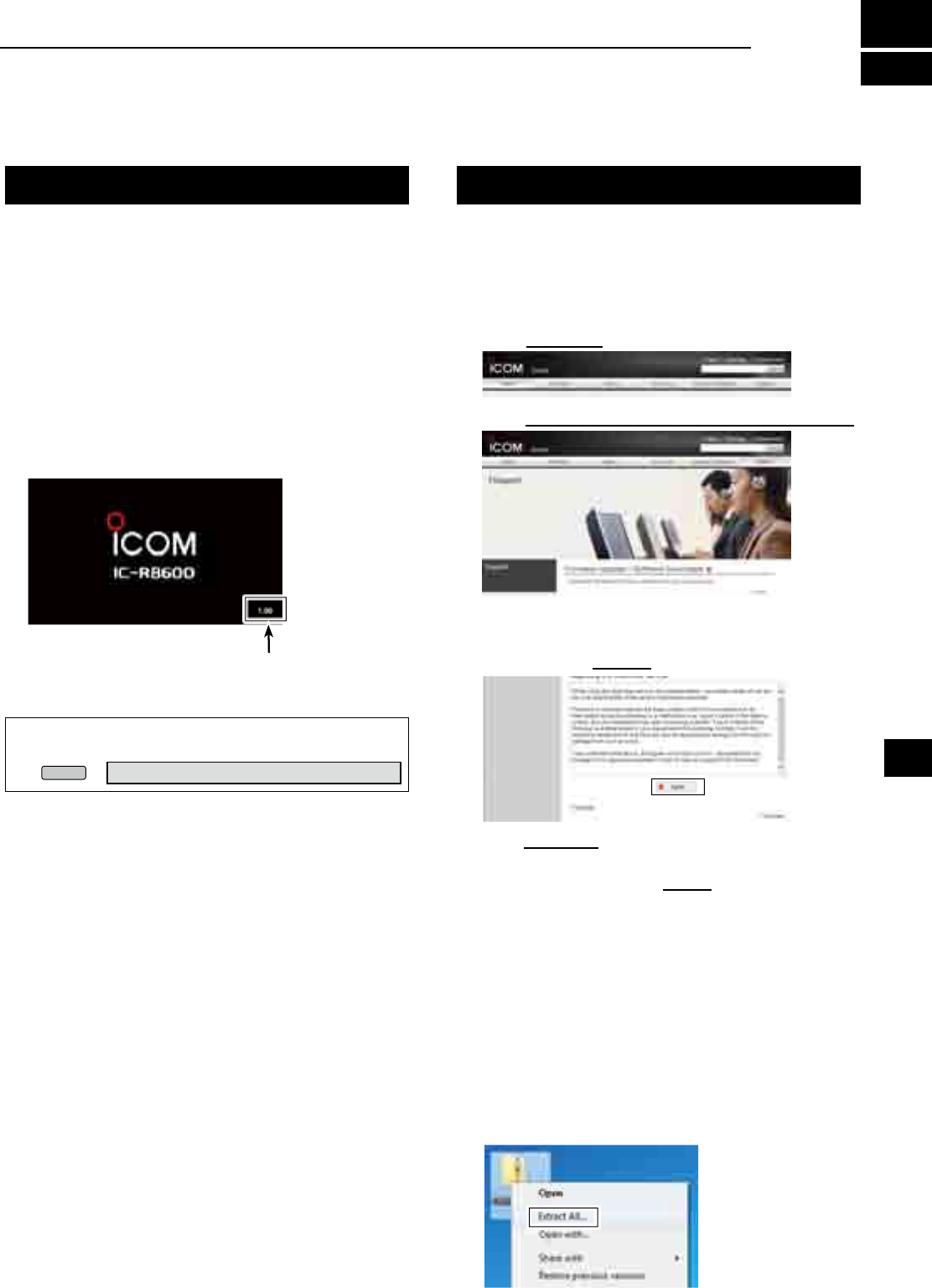
13-1
General Preparation
D About updating the fi rmware
You can update the IC-R8600’s fi rmware using an SD
card. Updating the fi rmware may add new functions
and improves performance parameters.
You can download the latest fi rmware from the Icom
website.
http://www.icom.co.jp/world/index.html
D Checking the fi rmware version
You can check the fi rmware version on the Opening
screen when you turn ON the receiver.
TIP: You can also check the fi rmware version on the
INFORMATION screen.
MENU
» SET > Others > Information > Version
The Main CPU's fi rmware version is displayed.
D Downloading the fi rmware fi le
Access the following URL and download the firmware file.
http://www.icom.co.jp/world/index.html
These instructions are based on Microsoft® Windows® 7.
1. Click [Support].
2. C l i c k “Firmware Updates/Software Downloads”.
3. Click the desired firmware file link.
4. Read “Regarding this Download Service” carefully,
and then click [Agree].
5.
Click “Save as” in the displayed File Download dialog.
6. Select the location where you want to save the
firmware, and then click [Save] in the displayed File
Download dialog.
• The fi le starts downloading.
•
The fi rmware and the fi rm utility are compressed in a “zip”
format folder. Unzip it before use.
D Unzipping the fi rmware folder
1. Right-click the downloaded firmware folder
(zip format).
• Right-click menu is displayed.
2. Click “Extract All...”
• After unzipping, a folder is created in the same location
as the downloaded folder.
In the “R8600_X*” folder, “8600XXXX.dat*” is created.
* X represents the release number.
13
UPDATING THE FIRMWARE
1
2
3
4
5
6
7
8
9
10
11
12
13
14
15
16
17
18
19
20
21
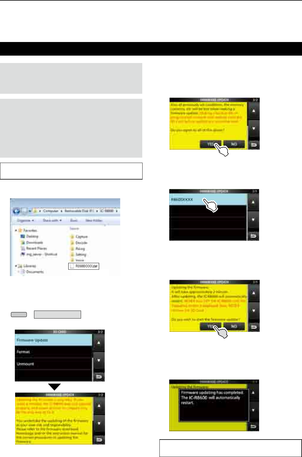
13-2
UPDATING THE FIRMWARE
13
Updating the fi rmware
IMPORTANT:
To update the fi rmware, fi rst format your
SD card using the IC-R8600. (p. 7-2) Then copy the
downloaded fi rmware data from your PC into the IC-
R8600 folder that was created on the SD card.
CAUTION:
NEVER turn OFF the receiver while
updating the fi rmware.
If you turn OFF the receiver, or if a power failure
occurs while updating, the fi rmware will be damaged
and you will have to send the receiver back to the
nearest Icom distributor for repair. This type of repair
is out of warranty, even if the receiver warranty period
is still valid.
TIP: BE SURE to unzip the downloaded fi le. See
“Unzipping the fi rmware fi le (p. 13-1)” for details.
1.
Copy the downloaded firmware data into the
IC-R8600 folder on the SD card.
2. Insert the SD card into the receiver's
[SD CARD] slot.
3. On the Set mode menu screen, display the
SD CARD screen.
MENU
» SET > SD card
4. Select “Firmware Update.”
The Firmware Update Agreement screen
Copy
TIP:
To check the fi rmware version after the updating,
see “Checking the fi rmware version (p. 13-1)” for details.
5. Touch [Ù] or [Ú] to scroll the screen.
Carefully read all the displayed precautions.
6. After you read and agree with all the precautions,
touch [YES].
• The fi le select screen is displayed.
If you want to cancel the updating, touch [NO].
7. Touch the Firmware (Example: 8600XXXX.dat*).
• The fi nal confi rmation screen is displayed.
Carefully read all the displayed precautions.
* X represents the release number.
8. After you read and agree with all the precautions,
touch [YES] for 1 second.
• The updating starts.
If you want to cancel the updating, touch [NO].
9. “Firmware updating has completed.” is displayed
in the dialog.
• The IC-R8600 will automatically restart.
After the updating fi nishes, the operating screen is
displayed.
14-1
DGeneral
• Frequency coverage:
USA
0.010000 ~ 821.999999 MHz*
851.000000 ~ 866.999999 MHz
896.000000 ~ 3000.000000 MHz
France
0.135700 ~ 0.137800 MHz
1.810000 ~ 1.850000 MHz
3.500000 ~ 3.800000 MHz
7.000000 ~ 7.200000 MHz
10.100000 ~ 10.150000 MHz
14.000000 ~ 14.350000 MHz
18.068000 ~ 18.168000 MHz
21.000000 ~ 21.450000 MHz
24.890000 ~ 24.990000 MHz
28.000000 ~ 29.700000 MHz
50.000000 ~ 52.000000 MHz
144.000000 ~ 146.000000 MHz
430.000000 ~ 440.000000 MHz
1240.000000 ~ 1300.000000 MHz
2300.000000 ~ 2450.000000 MHz
Other than above
0.010000 ~ 3000.000000 MHz*
*Some frequency ranges are not guaranteed.
• Receiving modes: SSB, CW, FSK, AM, FM, WFM and DIGITAL ( D-STAR, P25, NXDN,
dPMR and DCR)
• Number of memory channels: 2000 (in 100 groups)
+ 400 (Scan edges: 100 (50 pairs), Auto Memory Write: 200 and Scan Skip: 100)
• Power supply requirement: 13.8 V DC (±15%)
• Grounding system: Negative
• Operating temperature range: –10°C to +60°C, +14°F to +140°F
• Frequency stability: Less than ±0.5 ppm
• Antenna connectors:
• Frequency resolution: 1 Hz (minimum)
• Power consumption: Standby 1.8 A
Maximum audio 2.0 A
• Dimensions (projections not included): 220 (W)×90 (H)×230 (D) mm, 8.7 (W)×3.5 (H)×9.1 (D) in
• Weight (approximately): 4.3 kg, 9.5 Ib
DReceiver
• Receive system: 0.010000 ~ 29.999999 MHz Direct sampling
30.000000 ~ 1099.999999 MHz Double superheterodyne
1100.000000 ~ 3000.000000 MHz Triple superheterodyne
• Sampling frequency: 122.88 MHz
• Intermediate frequencies:
[ANT1] [ANT2] [ANT3]
Frequency range 10 kHz ~ 3000 MHz 10 kHz ~ 30 MHz 10 kHz ~ 30 MHz
Impedance 50 Ω Unbalanced 50 Ω Unbalanced 500 Ω Unbalanced
Connector N type SO-239 RCA
Receive frequency (MHz) 1st IF (MHz) 2nd IF (MHz) 3rd IF (MHz)
0.010000 ~ 29.999999 – – –
30.000000 ~ 499.999999 778.7 46.35 –
500.000000 ~ 1099.999999 278.7 46.35 –
1100.000000 ~ 1499.999999
900 ~ 500.00001
278.7 46.35
1500.000000 ~ 3000.000000 1000 ~ 500 278.7 46.35
14
SPECIFICATIONS
1
2
3
4
5
6
7
8
9
10
11
12
13
14
15
16
17
18
19
20
21

14-2
• Sensitivity:
SSB/CW/FSK (BW: SSB/FSK=2.4 kHz, CW=500 Hz)
0.100000 ~ 1.799999 MHz 10 dB S/N –6 dBμ (P.AMP ON)
1.800000 ~ 29.999999 MHz 10 dB S/N –14 dBμ (P.AMP ON)
30.000000 ~ 1099.999999 MHz 10 dB S/N –10 dBμ (P.AMP ON)
1100.000000 ~ 1999.999999 MHz 10 dB S/N –10 dBμ (P.AMP ON)
2000.000000 ~ 3000.000000 MHz 10 dB S/N –8 dBμ (P.AMP ON)
AM (BW=6 kHz)
0.100000 ~ 1.799999 MHz 10 dB S/N 16 dBμ (P.AMP ON)
1.800000 ~ 29.999999 MHz 10 dB S/N 8 dBμ (P.AMP ON)
30.000000 ~ 1099.999999 MHz 10 dB S/N 15 dBμ (P.AMP ON)
1100.000000 ~ 1999.999999 MHz 10 dB S/N 15 dBμ (P.AMP ON)
2000.000000 ~ 3000.000000 MHz 10 dB S/N 15 dBμ (P.AMP ON)
FM (BW=15 kHz)
28.000000 ~ 29.999999 MHz 12 dB SINAD –6 dBμ (P.AMP ON)
30.000000 ~ 1099.999999 MHz 12 dB SINAD –6 dBμ (P.AMP ON)
1100.000000 ~ 1999.999999 MHz 12 dB SINAD –6 dBμ (P.AMP ON)
2000.000000 ~ 3000.000000 MHz 12 dB SINAD –4 dBμ (P.AMP ON)
WFM (BW=180 kHz)
30.000000 ~ 1099.999999 MHz 12 dB SINAD 3 dBμ (P.AMP ON)
1100.000000 ~ 1999.999999 MHz 12 dB SINAD 3 dBμ (P.AMP ON)
2000.000000 ~ 3000.000000 MHz 12 dB SINAD 5 dBμ (P.AMP ON)
DIGITAL (D-STAR, NXDN, dPMR and DCR)
28.000000 ~ 1099.999999 MHz 1% BER –2 dBμ (P.AMP ON)
1100.000000 ~ 1999.999999 MHz 1% BER –2 dBμ (P.AMP ON)
2000.000000 ~ 3000.000000 MHz 1% BER 0 dBμ (P.AMP ON)
DIGITAL (P25)
28.000000 ~ 1099.999999 MHz 5% BER –5 dBμ (P.AMP ON)
1100.000000 ~ 1999.999999 MHz 5% BER –5 dBμ (P.AMP ON)
2000.000000 ~ 3000.000000 MHz 5% BER –3 dBμ (P.AMP ON)
• Selectivity:
SSB/FSK (BW=2.4 kHz) More than 2.4 kHz/–3 dB
Less than 3.6 kHz/–60 dB
CW (BW=500 Hz) More than 500 Hz/–3 dB
Less than 700 Hz/–60 dB
AM (BW=6 kHz) More than 6.0 kHz/–3 dB
Less than 15.0 kHz/–60 dB
FM (BW=15 kHz) More than 12.0 kHz/–6 dB
Less than 25.0 kHz/–60 dB
WFM More than 180 kHz/–6 dB
• Spurious and image rejection:
0.100000 ~ 29.999999 MHz More than 70 dB
30.000000 ~ 1099.999999 MHz More than 50 dB
1100.000000 ~ 2499.999999 MHz More than 40 dB*
2500.000000 ~ 3000.000000 MHz More than 40 dB*
*In the 1100 MHz and above frequencies, the 1st IF through is more than 35 dB.
*In the 2000 MHz and above frequencies, the 1st IF image rejection is more than 30 dB.
• Audio output power: More than 2 W (8 Ω load, 10% distortion)
• AF output impedance: 8 Ω
LAll stated specications are typical and subject to change without notice or obligation.
DReceiver (continued)
14 SPECIFICATIONS
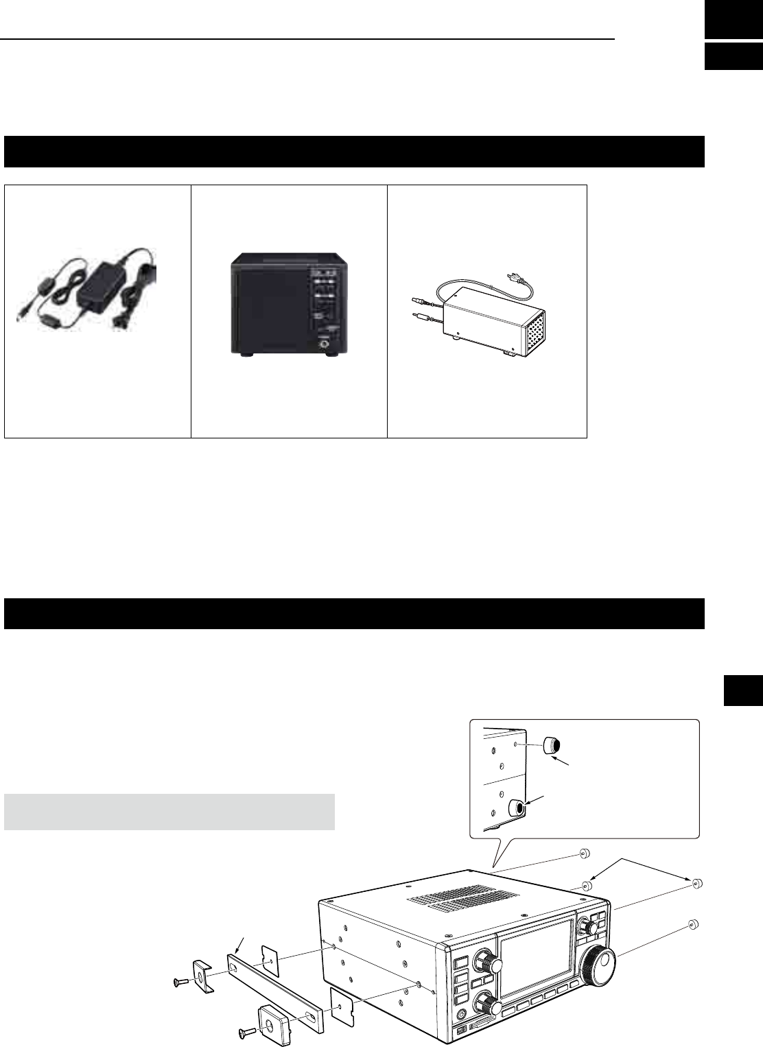
15-1
Options
Approved Icom optional equipment is designed for optimal performance when used with an Icom receiver. Icom
is not responsible for the destruction or damage to an Icom receiver in the event the Icom receiver is used with
equipment that is not manufactured or approved by Icom.
• 15 V/2 A
• 15 V/2 A
• 4 W/8 Ω
• Same height as the IC-R8600.
(Has a desktop stand.)
external speaker
with built-in power supply
• 4 W/8 Ω
L145.0(W)×111.0(H)×282.5(D) mm
5.7(W)×4.4(H)×11.1(D) mm
(Projections not included)
zCAB-1258 DC power cable ( approximately 3 m,
9.8 ft: repair parts)
zMB-123 Carrying handle
zRS-R8600 Remote control software
(Future product)
zCS-R8600 Programming Software
Attaching the MB-123
R WARNING! NEVER use other than the screws
supplied with the MB-123.
Rubber feet
(Supplied with MB-123)
Push-in the center part
Rubber feet
Carrying handle
The optional MB-123 carrying handle with the rubber
feet is convenient for carrying the receiver.
1. Attach the rubber feet supplied with the MB-123 to
the receiver.
2. Attach the carrying handle using the supplied
screws as shown to the right.
AD-55NS
AC adaptor
L The shape may differ,
depending on the version.
SP-23
external speaker
SP-39AD
15
OPTIONS
L To rmly attach, push-in the center part of the rubber feet.
1
2
3
4
5
6
7
8
9
10
11
12
13
14
15
16
17
18
19
20
21
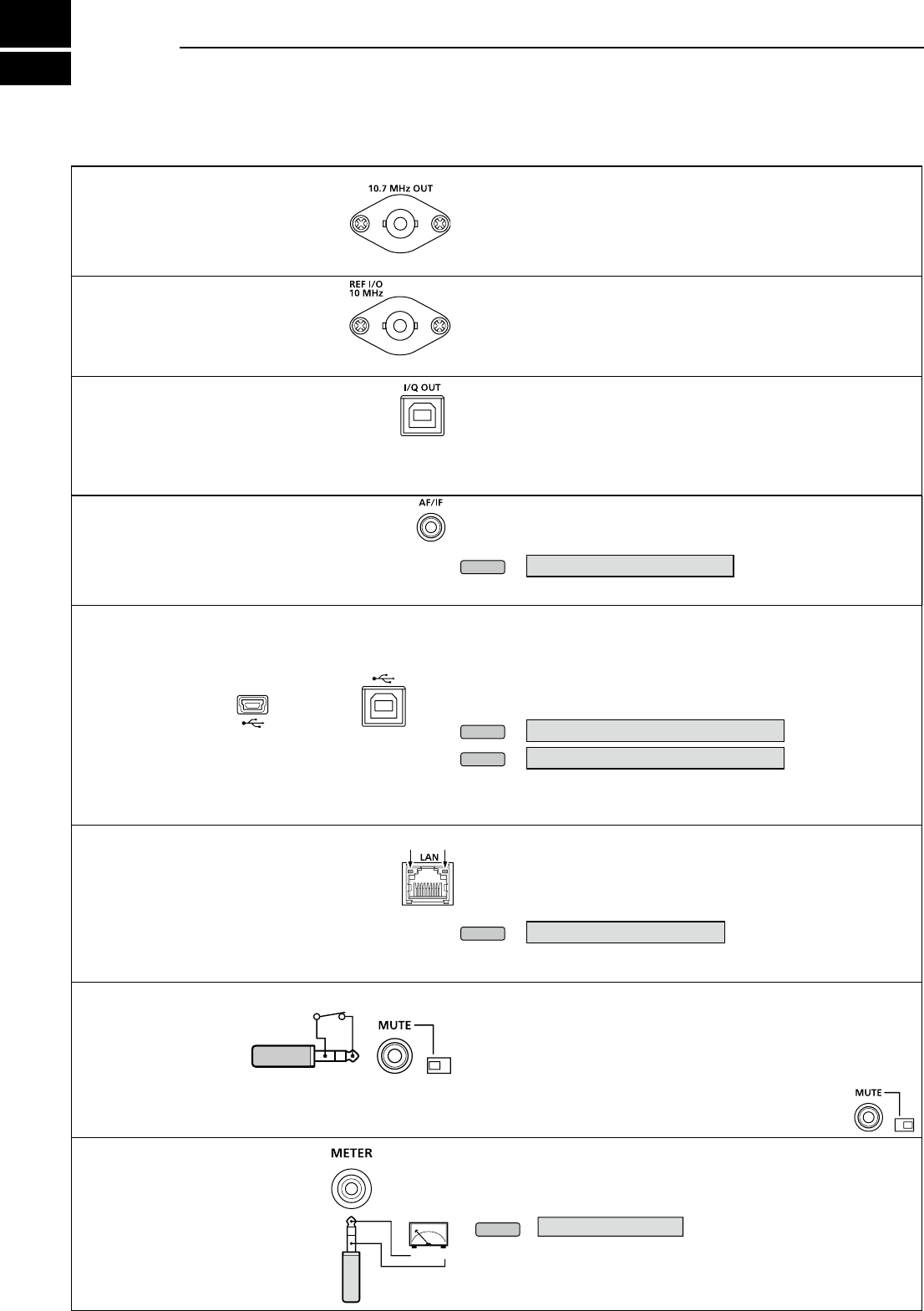
16-1
[10.7 MHz OUT]
Outputs the 10.7 MHz IF signal for
an external detector/demodulator circuit.
• Center frequency: 10.7 MHz
• Band width*: 10 MHz
• Impedance:50 Ω (unbalanced)
• Maximum output level:-10dBm (approximately)
*The band width is xed regardless of the digital PBT lter setting.
[REF I/O 10 MHz]
Outputs or inputs a 10 MHz
reference frequency signal.
You can change the signal direction
in the Set mode.
• Center frequency:10 MHz
• Impedance: 50 Ω (unbalanced)
• Input/Output level: –10 dBm (approximately)
• Frequency stability:
±0.5 ppm
(–10°C ~ +60°C, +14°F ~ +140 °F)
[I/Q OUT]
Outputs the Phase/Quadrature data which is
processed by the FPGA.
Connect a PC's USB port, to demodulate the DRM
broadcast or Software Dened Radio SDR.
• Interface: USB (1.1/2.0), type B
L
Icom does not provide any support regarding SDR technology and
related software, except the inspection for the normality of output signal.
L The IQ driver and instruction guide will be released on the Icom
website near future.
http://www.icom.co.jp/world/index.html
[AF/IF]
Outputs the demodulate audio signal or 12 kHz IF
signal (unltered). The output level is xed, regardless
of the volume control position. (3.5 mm, 1/8 in (d))
• Impedance: 4.7 kΩ
• Output level: 100 ~ 300 mV (RMS)
LYou can select the output signal from AF or IF signals.
MENU
» SET > Connectors > AF/IF
LThe signal is also output from [USB] (front or rear) or [LAN].
[USB]
2 USB ports: Type B mini and Type B.
L You can download the USB driver and installation
guide from the Icom website.
http://www.icom.co.jp/world/support/download/rm
• Outputs the decoded FSK (RTTY) signal, or D-STAR data.
• Outputs the demodulated signal or 12 kHz IF signal.
• Remote control interface for optional RS-R8600 (feature product).
• Programming interface for the optional CS-R8600.
L You can change the port settings (FSK decode data/D-STAR data,
AF/IF), baud rate and output level)
MENU
» SET > Connectors > USB (Front)
MENU
» SET > Connectors > USB (Rear)
[LAN]
LED indication:
q
LINK/ACT Lights: Cable connected.
Doesn't light: Cable not connected.
Blinks: While the line is communicating.
w
Speed Lights: Communicating in 100BASE-TX
Doesn't lights: Communicating.
in10BASE-T, or not connected.
• Time synchronization by an NTP server.
• Outputs the demodulated signal or 12 kHz IF signal.
• Remote control interface for the optional RS-R8600 (future
product).
LYou can select the output signal from AF and IF signals.
MENU
» SET > Connectors > LAN
[MUTE] JACK / [MUTE] SWITCH
Used to mute the receiver
output.
(3.5 mm, 1/8 in (d))
When the Mute Switch is slid to right, the receiver
enters to the Bit Error Rate (BER) Measurement mode
for the maintenance purpose.
When the [MUTE] is slid to left:
When this terminal is grounded, the receive circuit is turned OFF.
L Use this function when you use the IC-R8600 with a transceiver.
LThe sink current is approximately 1 mA at 8 V input.
When the [MUTE] is slid to right:
Connect a BER counter. In the BER Measurement mode,
the PN9 bit stream is output from this terminal.
[METER]
Connects to an external meter.
Outputs the received signal
strength or squelch level.
(3.5 mm, 1/8 in (d))
• Output voltage: 8 V (maximum)
• Output impedance: 10 kΩ
L You can select the output signal from received signal strength
and squelch levels.
MENU
» SET > Connectors
q w
+_
16 CONNECTOR INFORMATION
BNC type
BNC type
On the front panel
miniB type B type
On the rear panel
Meter output
Mute
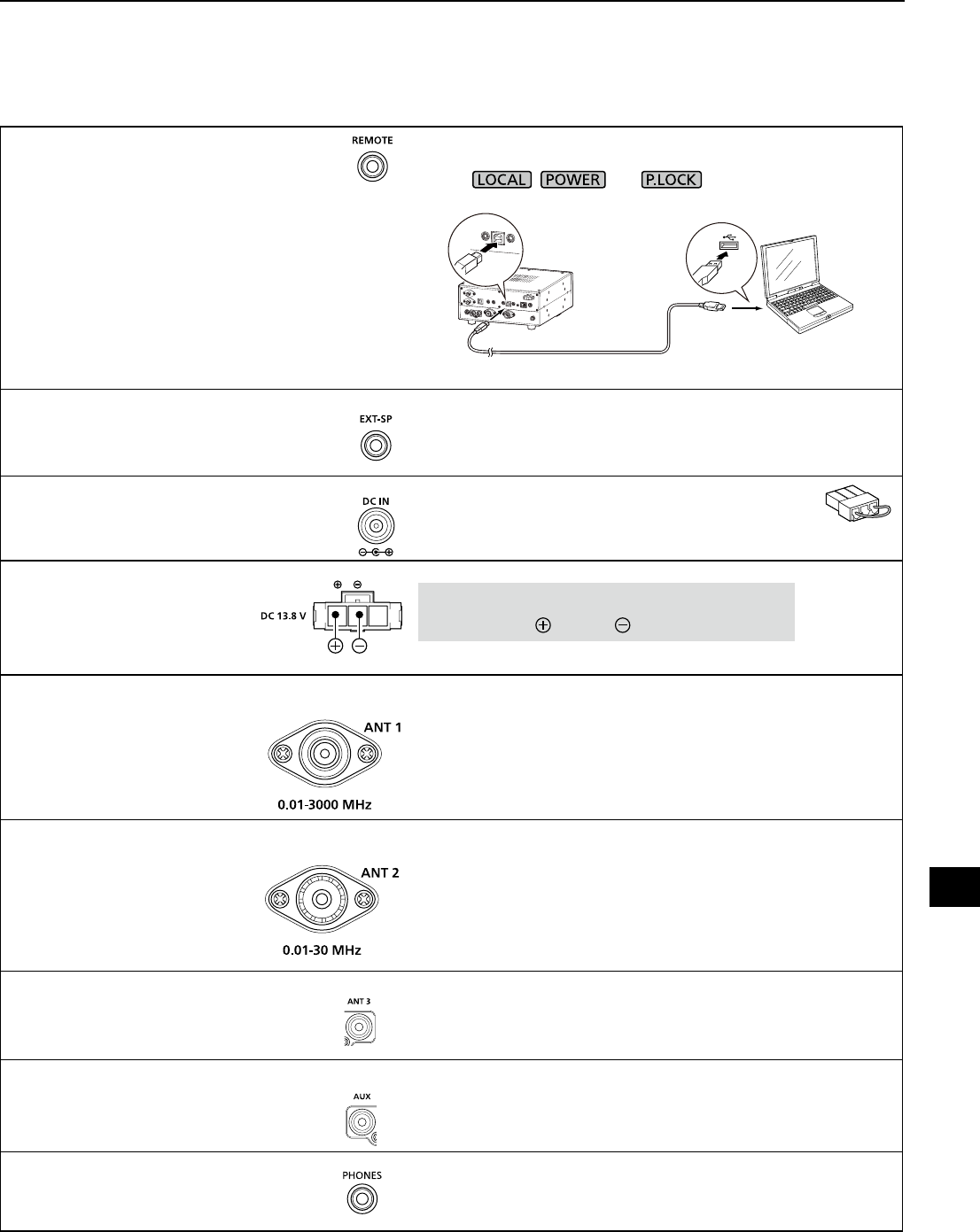
16-2
[REMOTE]
Used to remotely controls the receiver with
the CI-V format data.
(3.5 mm, 1/8 in (d))
L You can download the USB driver and installation
guide from the Icom website.
http://www.icom.co.jp/world/support/download/rm
In the remote control mode, push [LOCAL] to return to the normal
(Local) mode (LOCAL LED turns OFF).
*Except , and .
Remote connection example with a PC
[EXT-SP]
Connects to an external speaker such as
the optional SP-39AD.
(3.5 mm, 1/8 in (d))
• Output impedance: 4 ~ 8 Ω
• Output level: More than 2 W at 10% distortion into an 8
Ω load.
[DC IN]
Connects to the optional
SP-39AD.
When SP-39AD or AD-55NS is connected,
connect the supplied DC short connector to [DC13.8V].
[DC13.8V]
Accepts the regulated DC power for
13.8 V DC (±15%), through the
supplied DC power cable.
WARNING! NEVER reverse the DC power cable
polarity (Red= , Black= ).
[ANT 1] • Frequency range: 10 kHz ~ 3000 MHz
• Input impedance: 50 Ω (unbalanced)
L When the receive frequency is set to between 10 kHz and
29.999999 MHz, you can select the antenna on [ANT 1] ~ [ANT
3]. (p. 3-3)
[ANT 2] • Frequency range: 10 kHz ~ 30 MHz
• Input impedance: 50 Ω (unbalanced)
[ANT 3]
LFor a long wire antenna.
• Frequency range: 10 kHz ~ 30 MHz
• Input impedance: 400 ~ 500 Ω (unbalanced)
[AUX]
A reserved terminal. No internal connection.
[PHONES]
Connects to standard stereo headphones.
(3.5 mm, 1/8 in (d))
• Output impedance: 8 ~ 16 Ω
• Output level: More than 50 mW (into an 8 Ω load)
SO-239
IC-R8600
USB cable (A-B type)
PC
16
CONNECTOR INFORMATION
1
2
3
4
5
6
7
8
9
10
11
12
13
14
15
16
17
18
19
20
21
View from the rear
N type
RCA type
RCA type

I
ABOUT THE LICENSES
Information on the open source software
being used by this product.
COPYRIGHT NOTICE, DISCLAIMER, and
LICENSE:
If you modify libpng you may insert
additional notices immediately following this
sentence.
This code is released under the libpng
license.
libpng versions 1.2.6, August 15, 2004,
through 1.6.12, June 12, 2014, are
Copyright (c) 2004, 2006-2014 Glenn
Randers-Pehrson, and are distributed
according to the same disclaimer and
license as libpng-1.2.5 with the following
individual added to the list of Contributing
Authors:
Cosmin Truta
libpng versions 1.0.7, July 1, 2000, through
1.2.5, October 3, 2002, are Copyright (c)
2000-2002 Glenn Randers-Pehrson, and
are distributed according to the same
disclaimer and license as libpng-1.0.6 with
the following individuals added to the list of
Contributing Authors:
Simon-Pierre Cadieux
Eric S. Raymond
Gilles Vollant
and with the following additions to the
disclaimer:
There is no warranty against interference
with your enjoyment of the library or
against infringement. There is no warranty
that our efforts or the library will fulll any
of your particular purposes or needs.
This library is provided with all faults,
and the entire risk of satisfactory quality,
performance, accuracy, and effort is with
the user.
libpng versions 0.97, January 1998, through
1.0.6, March 20, 2000, are Copyright (c)
1998, 1999, 2000 Glenn Randers-Pehrson,
and are distributed according to the same
disclaimer and license as libpng-0.96, with
the following individuals added to the list of
Contributing Authors:
Tom Lane
Glenn Randers-Pehrson
Willem van Schaik
libpng versions 0.89, June 1996, through
0.96, May 1997, are Copyright (c) 1996,
1997 Andreas Dilger Distributed according
to the same disclaimer and license as
libpng-0.88, with the following individuals
added to the list of Contributing Authors:
John Bowler
Kevin Bracey
Sam Bushell
Magnus Holmgren
Greg Roelofs
Tom Tanner
libpng versions 0.5, May 1995, through 0.88,
January 1996, are Copyright (c) 1995, 1996
Guy Eric Schalnat, Group 42, Inc.
For the purposes of this copyright and
license, "Contributing Authors" is dened as
the following set of individuals:
Andreas Dilger
Dave Martindale
Guy Eric Schalnat
Paul Schmidt
Tim Wegner
The PNG Reference Library is supplied "AS
IS". The Contributing Authors and Group
42, Inc. disclaim all warranties, expressed
or implied, including, without limitation, the
warranties of merchantability and of tness
for any purpose. The Contributing Authors
and Group 42, Inc. assume no liability
for direct, indirect, incidental, special,
exemplary, or consequential damages,
which may result from the use of the PNG
Reference Library, even if advised of the
possibility of such damage.
Permission is hereby granted to use, copy,
modify, and distribute this source code, or
portions hereof, for any purpose, without
fee, subject to the following restrictions:
1. The origin of this source code must not
be misrepresented.
2. Altered versions must be plainly marked
as such and must not be misrepresented
as being the original source.
3. This Copyright notice may not be
removed or altered from any source or
altered source distribution.
The Contributing Authors and Group 42,
Inc. specically permit, without fee, and
encourage the use of this source code
as a component to supporting the PNG
le format in commercial products. If
you use this source code in a product,
acknowledgment is not required but would
be appreciated.
A "png_get_copyright" function is available,
for convenient use in "about" boxes and the
like:
printf("%s", png_get_copyright(NULL));
Also, the PNG logo (in PNG format, of
course) is supplied in the les "pngbar.png"
and "pngbar.jpg (88x31) and "pngnow.png"
(98x31).
Libpng is OSI Certied Open Source
Software. OSI Certied is a certication
mark of the Open Source Initiative.
The contributing authors would like to thank
all those who helped with testing, bug xes,
and patience. This wouldn't have been
possible without all of you.
Thanks to Frank J. T. Wojcik for helping with
the documentation.
License for CMSIS-RTOS RTX
Implementation
Copyright (c) 1999-2009 KEIL, 2009-2013
ARM Germany GmbH All rights reserved.
Redistribution and use in source and
binary forms, with or without modication,
are permitted provided that the following
conditions are met:
- Redistributions of source code must
retain the above copyright notice, this list
of conditions and the following disclaimer.
- Redistributions in binary form must
reproduce the above copyright
notice, this list of conditions and the
following disclaimer in the documentation
and/or other materials provided with the
distribution.
- Neither the name of ARM nor the names
of its contributors may be used
to endorse or promote products derived
from this software without specic prior
written permission.
THIS SOFTWARE IS PROVIDED BY
THE COPYRIGHT HOLDERS AND
CONTRIBUTORS "AS IS" AND ANY
EXPRESS OR IMPLIED WARRANTIES,
INCLUDING, BUT NOT LIMITED TO,
THE IMPLIED WARRANTIES OF
MERCHANTABILITY AND FITNESS
FOR A PARTICULAR PURPOSE
ARE DISCLAIMED. IN NO EVENT
SHALL COPYRIGHT HOLDERS
AND CONTRIBUTORS BE LIABLE
FOR ANY DIRECT, INDIRECT,
INCIDENTAL, SPECIAL, EXEMPLARY,
OR CONSEQUENTIAL DAMAGES
(INCLUDING, BUT NOT LIMITED TO,
PROCUREMENT OF SUBSTITUTE
GOODS OR SERVICES; LOSS OF USE,
DATA, OR PROFITS; OR BUSINESS
INTERRUPTION) HOWEVER CAUSED
AND ON ANY THEORY OF LIABILITY,
WHETHER IN CONTRACT, STRICT
LIABILITY, OR TORT (INCLUDING
NEGLIGENCE OR OTHERWISE) ARISING
IN ANY WAY OUT OF THE USE OF THIS
SOFTWARE, EVEN IF ADVISED OF THE
POSSIBILITY OF SUCH DAMAGE.
ZLIB DATA COMPRESSION LIBRARY
zlib 1.2.8 is a general purpose data
compression library. All the code is thread
safe. The data format used by the zlib
library is described by RFCs (Request for
Comments) 1950 to 1952 in the les http://
tools.ietf.org/html/rfc1950 (zlib format),
rfc1951 (deate format) and rfc1952 (gzip
format).
All functions of the compression library are
documented in the le zlib.h (volunteer to
write man pages welcome, contact zlib@
gzip.org). A usage example of the library is
given in the le test/example.c which also
tests that the library is working correctly.
Another example is given in the le test/
minigzip.c. The compression library itself
is composed of all source les in the root
directory.
To compile all les and run the test program,
follow the instructions given at the top of
Makele.in. In short "./congure; make test",
and if that goes well, "make install" should
work for most avors of Unix. For Windows,
use one of the special makeles in win32/
or contrib/vstudio/ . For VMS, use make_
vms.com.
Questions about zlib should be sent to
<zlib@gzip.org>, or to Gilles Vollant <info@
winimage.com> for the Windows DLL
version. The zlib home page is http://zlib.
net/ . Before reporting a problem, please
check this site to verify that you have the
latest version of zlib; otherwise get the latest
version and check whether the problem still
exists or not.
PLEASE read the zlib FAQ http://zlib.net/
zlib_faq.html before asking for help.
Mark Nelson <markn@ieee.org> wrote
an article about zlib for the Jan. 1997
issue of Dr. Dobb's Journal; a copy of the
article is available at http://marknelson.
us/1997/01/01/zlib-engine/ .
The changes made in version 1.2.8 are
documented in the le ChangeLog.
Unsupported third party contributions are
provided in directory contrib/ .
zlib is available in Java using the java.
util.zip package, documented at http://
java.sun.com/developer/technicalArticles/
Programming/compression/ .
A Perl interface to zlib written by Paul
Marquess <pmqs@cpan.org> is available
at CPAN (Comprehensive Perl Archive
Network) sites, including http://search.cpan.
org/~pmqs/IO-Compress-Zlib/ .
A Python interface to zlib written by A.M.
Kuchling <amk@amk.ca> is available in
Python 1.5 and later versions, see http://
docs.python.org/library/zlib.html .
zlib is built into tcl: http://wiki.tcl.tk/4610 .
An experimental package to read and write
les in .zip format, written on top of zlib by
Gilles Vollant <info@winimage.com>, is
available in the contrib/minizip directory of
zlib.
Notes for some targets:
- For Windows DLL versions, please see
win32/DLL_FAQ.txt
- For 64-bit Irix, deate.c must be compiled
without any optimization. With
- O, one libpng test fails. The test works in
32 bit mode (with the -n32 compiler ag).
The compiler bug has been reported to
SGI.
- zlib doesn't work with gcc 2.6.3 on a DEC
3000/300LX under OSF/1 2.1 it works
when compiled with cc.
- On Digital Unix 4.0D (formely OSF/1)
on AlphaServer, the cc option -std1 is
necessary to get gzprintf working correctly.
This is done by congure.
- zlib doesn't work on HP-UX 9.05 with
some versions of /bin/cc. It works with
other compilers. Use "make test" to check
your compiler.
- gzdopen is not supported on RISCOS or
BEOS.
- For PalmOs, see http://palmzlib.
sourceforge.net/
Acknowledgments:
The deate format used by zlib was
dened by Phil Katz. The deate and
zlib specications were written by L.
Peter Deutsch. Thanks to all the people
who reported problems and suggested
various improvements in zlib; they are too
numerous to cite here.
Copyright notice:
(C) 1995-2013 Jean-loup Gailly and Mark
Adler
This software is provided 'as-is', without any
express or implied warranty. In no event will
the authors be held liable for any damages
arising from the use of this software.
Permission is granted to anyone to use
this software for any purpose, including
commercial applications, and to alter it and
redistribute it freely, subject to the following
restrictions:
1. The origin of this software must not be
misrepresented; you must not claim
that you wrote the original software.
If you use this software in a product,
an acknowledgment in the product
documentation would be appreciated but
is not required.
2. Altered source versions must be plainly
marked as such, and must not be
misrepresented as being the original
software.
3. This notice may not be removed or
altered from any source distribution.
Jean-loup Gailly Mark Adler
jloup@gzip.org madler@alumni.caltech.edu
If you use the zlib library in a product, we
would appreciate *not* receiving lengthy
legal documents to sign. The sources are
provided for free but without warranty of any
kind. The library has been entirely written
by Jean-loup Gailly and Mark Adler; it does
not include third-party code.
If you redistribute modied sources, we
would appreciate that you include in the le
ChangeLog history information documenting
your changes. Please read the FAQ for
more information on the distribution of
modied source versions.

INDEX
1
2
3
4
5
6
7
8
9
10
11
12
13
14
15
16
17
18
19
20
21
II
II
Symbols
∂F scan ..................................................................9-5
∂F scan operation ..................................................9-5
[NOTCH] Switch ...................................................11-3
[P.LOCK] Switch ...................................................11-3
[SPEECH/LOCK] Switch ......................................11-3
Number
2nd DNS Server (Valid after Restart) ...................11-7
A
Auto Tuning Step function ......................................3-3
ABOUT THE INSTRUCTIONS ................................. iv
About the VFO and Memory modes .......................3-1
AF Beep/Speech... Output...........................11-5, 11-6
AFC function ...........................................................5-5
AFC Limit ..............................................................11-3
AF Output Level....................................................11-5
AF Speech Output ................................................11-6
AF SQL ........................................................11-5, 11-6
AGC function ..........................................................5-1
AGC Time constant ................................................5-1
Antenna
About antenna ............................................ 2-2, 3-3
Connecting an antenna ......................................2-2
Antenna connectors ............................... 14-1, 16-2
Selecting the antenna ................................ 3-3, 5-1
Attenuator ...............................................................5-1
Audio
Audio tone ..........................................................3-1
Bass .................................................................11-2
De-Emphasis ....................................................11-2
HPF/LPF ..........................................................11-2
Tone Control .....................................................11-2
Treble ...............................................................11-2
Volume level .......................................................3-1
Audio Port (UDP) ..................................................11-8
Auto Memory Write scan ........................................9-6
B
Backlight dimmer ....................................................3-4
Beep (Conrmation) .............................................11-2
Beep Level .......................................................11-2
Beep Level Limit ...............................................11-2
BER Measurement .............................................11-10
BW Popup (FILTER) .............................................11-9
BW Popup (PBT) ..................................................11-9
C
CC ........................................................................5-10
CI-V
Address ............................................................11-6
Baud Rate ........................................................11-6
Baud Rate (Front USB port) ............................11-6
Baud Rate (Rear USB port) ............................11-7
Echo Back (Front USB port) ............................11-6
Echo Back (Rear USB port) ............................11-7
Port (Rear USB port) .......................................11-7
Transceive ........................................................11-6
Cleaning ...............................................................12-1
Clock
NTP Function .................................................11-10
NTP Server address .......................................11-10
NTP Server address setting .............................10-1
NTP TIME .......................................................11-10
NTP Time Server ..............................................10-1
Setting date and time .......................................10-1
Time Set .........................................................11-10
Time synchronization .......................................10-1
UTC Offset .....................................................11-10
Clone Mode ........................................................11-10
COM ID (Common ID) ..........................................5-10
CONNECTOR INFORMATION ............................16-1
Connectors ...........................................................11-5
Control Port (UDP) (Valid after Restart) ...............11-8
Copying the Memory contents ................................8-3
CW
CW .....................................................................5-5
Normal Side .....................................................11-3
Reversing the carrier point .................................5-5
D
Daily timer .............................................................10-2
Date ...........................................................11-4, 11-10
DC power supply ....................................................2-1
Decoding FSK signal ..............................................5-5
Decryption function ...............................................5-10
De-Emphasis ........................................................11-2
Default Gateway (Valid after Restart) ...................11-7
Descrambler function............................................5-10
DHCP (Valid after Restart) ...................................11-7
DIAL A .....................................................................1-2
DIAL B ....................................................................1-1
DIAL C ....................................................................1-2
Dial Lock function ...................................................3-3
Dial/Panel Lock function .........................................3-3
Digital Code Squelch ..............................................5-9
Digital IF lter..........................................................5-3
Digital Mode Select...............................................11-4
Digital Monitor.......................................................11-4
Digital Set .............................................................11-4
Digital Squelch........................................................5-9
Digital Twin PBT .....................................................5-2
Directly entering a frequency ..................................3-2
Display Type .........................................................11-9

INDEX
III
III
DISPOSAL ................................................................ iii
Downloading the rmware le ..............................13-1
dPMR....................................................................5-10
D.SQL (Digital Squelch) function ............................5-9
D-STAR Auto Detect .............................................11-4
D-STAR Data Baud Rate .............................11-5, 11-6
D-STAR EMR AF Level ........................................11-4
D-STAR Standby Beep ......................................... 11-4
DTCS codes ...........................................................5-9
Duplex operation ....................................................5-4
E
Entering a frequency ..............................................3-2
Entering a group/memory name .............................8-4
Entering a group name ...........................................8-4
Entering a memory name .......................................8-4
Entering and editing characters ..............................1-7
Entering the Set mode ..........................................11-1
Entry example (Group and memory name) ............1-8
External device connection.....................................2-3
External Meter Level.............................................11-7
External Meter Output ..........................................11-7
F
FCC INFORMATION ................................................ iii
FEATURES ................................................................ ii
FFT scope zone ......................................................4-3
Fine ∂F scan operation ..........................................9-5
Fine Programmed scan ..........................................9-4
Fine Programmed scan operation ..........................9-4
Fine tuning ..............................................................3-4
Firmware
Download URL .................................................13-1
Updating ...........................................................13-2
Version ...........................................................11-10
Version checking ..............................................13-1
Unzipping the rmware folder ..........................13-1
Fixed mode screen .................................................4-1
Formatting an SD card ...........................................7-2
Frequency coverage .............................................14-1
Front panel .............................................................1-1
FSK (RTTY)
Decode ...............................................................5-5
Decoder ..............................................................2-2
Decode Baud Rate ..................................11-5, 11-6
DECODE SET screen ........................................5-8
Decode setting ...................................................5-8
Logging ..............................................................5-6
Log view .............................................................5-7
Receiving FSK (RTTY) signal ............................5-5
Shift setting ........................................................5-7
Tone and shift setting .........................................5-7
FUNCTION KEY .....................................................1-1
FUNCTION screen .................................. 1-7, 5-1, 5-6
Function menu keys ...............................................4-1
Fuse
Circuitry fuse ....................................................12-1
DC power cable fuses ......................................12-1
Replacement ....................................................12-1
G
Grounding ...............................................................2-1
Group Code (COM ID) and CC ............................5-10
Group Name Popup..............................................11-9
H
Headphones ...........................................................2-3
Heat dissipation ......................................................2-1
History log.............................................................5-11
HPF/LPF ...............................................................11-2
I
IF
IF lter ................................................................5-3
IF lter passband widths ....................................5-3
IF lter shape .....................................................5-3
IF Output Level ........................................11-5, 11-6
Digital IF lter .....................................................5-3
Twin Peak Filter .................................................. 5-7
Using the Digital Twin PBT .................................5-2
IMPORTANT ...............................................................i
Inserting a blank channel........................................8-3
Inserting or removing the SD card ..........................7-1
Interfere prevention ................................................2-1
Internet Access Line .............................................11-8
IP Address (Valid after Restart) ............................11-7
IP Plus function .......................................................5-2
K
Keyboard
Entering and editing ...........................................1-7
Full Keyboard .....................................................1-8
Keyboard Type .................................................11-4
Tenkey ................................................................1-8
L
Language
Display Language ............................................11-9
System Language ............................................11-9
LAN port .................................................................2-3
LCD Backlight .......................................................11-9
LED Bright ............................................................11-9
Loading the setting data .........................................7-3
Load setting ........................................................ 11-10

INDEX
1
2
3
4
5
6
7
8
9
10
11
12
13
14
15
16
17
18
19
20
21
IVIV
M
MAIN DIAL ..............................................................1-1
MAIN DIAL Auto TS ..............................................11-3
MB-123 (Optional) attachment .............................15-1
Memory channel
Entry example (Group and memory name) ........1-8
Inserting a blank channel ...................................8-3
Memory channels ...............................................8-1
Memory channel clearing ...................................8-3
Memory channel group name ............................8-4
Memory channel group select screen ................8-1
Memory channel group selecting .......................8-1
Memory channel name .......................................8-4
Memory channel tree view .................................8-1
Memory contents copying ..................................8-3
Memory Name ..................................................11-9
MEMORY screen ...............................................8-5
Selecting a memory channel ..............................8-2
Selecting channel group .....................................8-1
Writing a memory channel .................................8-2
MENU KEY .............................................................1-1
MENU screen .........................................................1-6
Meter
Meter display types ............................................3-4
Meter Peak Hold ..............................................11-9
Mini scope screen...................................................4-3
MN-Q Popup.........................................................11-9
Mode select memory scan......................................9-9
MODE SPEECH ...................................................11-2
Monitor function ......................................................3-1
Monitoring the Priority channel ...............................9-2
MULTI DIAL MENU .................................................1-6
N
NAC ........................................................................5-9
Network
2nd DNS Server ...............................................11-7
Audio Port (UDP) .............................................11-8
Control Port (UDP) ...........................................11-8
Default Gateway ...............................................11-7
Internet Access Line .........................................11-8
IP Address ........................................................11-7
LAN port .............................................................2-3
Network Access Code (NAC) .............................5-9
Network Control ...............................................11-8
Network Name .................................................11-8
Network Radio Name .......................................11-8
Network User Administrator .............................11-8
Network User ID ...............................................11-8
Network User Password ...................................11-8
Primary DNS Server .........................................11-7
Serial Port (UDP) .............................................11-8
Subnet Mask ....................................................11-7
Transceive Address ..........................................11-6
Noise Blanker (NB) .................................................5-4
Noise reduction.......................................................5-4
Normal recording ....................................................6-1
Notch Filter .............................................................5-2
Notching width and frequency ................................5-2
NTP Function ......................................................11-10
NTP Server Address ...........................................11-10
NTP TIME ...........................................................11-10
NTP Time Server ..................................................10-1
O
Opening Comment ...............................................11-9
Opening Message ................................................11-9
Options .................................................................15-1
Output Select ...............................................11-5, 11-6
P
P25 .........................................................................5-9
P25 RX ID Display ................................................11-9
Panel Lock function ................................................3-3
Partial reset ...............................................11-10, 12-2
Peak signal .............................................................4-3
Phones Level Ratio ..............................................11-5
Playback screen .....................................................6-2
PLAYER SET screen ..............................................6-4
Playing back ...........................................................6-1
Power consumption ..............................................14-1
Power OFF Setting (for Remote Control) .............11-8
Power supply ..........................................................2-1
Power supply requirement ....................................14-1
Preamplier ............................................................5-1
PRECAUTIONS .......................................................viii
Primary DNS Server (Valid after Restart) .............11-7
Priority scan
About the Priority scan .......................................9-1
Monitoring the Priority channel ...........................9-2
Priority interval ...................................................9-2
Priority scan operation .......................................9-2
Programmable Tuning Step function ..................3-3
Programmed scan ..................................................9-4
Q
QUICK MENU .........................................................1-6
Quick recording ......................................................6-1
R
Radio Access Number (RAN) ...............................5-10
Rear panel ..............................................................1-3
Receive frequency ..................................................3-2
Receive history log ...............................................5-11
Receiving mode ......................................................3-1
Receiving modes ..................................................14-1
Recording
Normal recording ................................................6-1
Operation while playing back .............................6-2
Playback screen .................................................6-2
PLAYER SET screen ..........................................6-4

INDEX
VV
Playing back .......................................................6-1
Playing back on a PC .........................................6-2
Quick recording ..................................................6-1
Recording setting ...............................................6-1
RECORDER SET screen ...................................6-4
REF (reference frequency) adjust ........................11-4
Reference level.......................................................4-4
REF IN/OUT .........................................................11-7
Reset
All reset .................................................11-10, 12-2
Partial reset ...........................................11-10, 12-2
Reversing the carrier point .....................................5-5
RF gain ...................................................................3-1
RX history items ...................................................5-11
RX History Log .....................................................11-4
RX Marker ..............................................................4-1
RX Popup .............................................................11-9
RX Record (D-STAR RPT) ...................................11-4
S
Save Setting .......................................................11-10
Saving data onto the SD card.................................7-1
Saving in the old format ..........................................7-2
Saving the setting data ...........................................7-2
Scan delay timer .....................................................9-2
Scan
∂F scan ..............................................................9-5
Basic scanning ...................................................9-1
Fine ∂F scan operation ......................................9-5
Fine Programmed scan ......................................9-4
Fine Programmed scan operation ......................9-4
Memory scan and Select Memory scan .............9-7
Memory scan operation ......................................9-7
Mode select memory scan .................................9-9
Scan Resume function .......................................9-2
Scan delay timer ................................................9-2
Scan Setting screen ...........................................9-3
SCAN SPEECH (at Receive Pause) ................ 11-2
Scan speed ........................................................9-1
Scan types .........................................................9-1
Select Memory channel ......................................9-7
Select Memory channel settings ........................9-8
Select Memory channel clearing ........................9-8
Select Memory channel setting ..........................9-8
Skip frequency ...................................................9-9
Temporary Skip ................................................9-10
Tone scan operation .........................................9-11
Programmed scan ..............................................9-4
VFO scan and Memory scan ..............................9-1
Spectrum scope
Center mode screen ...........................................4-1
Reference level ..................................................4-4
Scope screen .....................................................4-1
Scope screen parameters ..................................4-5
Scope set screen ...............................................4-5
Waterfall zone ....................................................4-3
Screen
Screen Capture File Type ................................11-4
Screen Capture function ..................................5-11
Screen Capture [POWER] Switch .................... 11-3
Screen Capture View .....................................11-10
Screen Saver ...................................................11-9
Touch screen calibration ..................................12-3
SD card...............................................................11-10
Audio le delete ..................................................6-3
Audio le folder delete ........................................6-4
Audio le information ..........................................6-3
Checking SD card information ...........................7-3
Checking the le information ..............................6-3
Formatting an SD card .......................................7-2
Inserting or removing .........................................7-1
Loading the data les .........................................7-3
SD card compatibility .........................................7-1
SD card data ......................................................7-1
SD card deleting a data le ................................7-3
SD card deleting a folder ....................................6-4
SD Card Info ..................................................11-10
SD card information ...........................................7-3
SD card loading data les ..................................7-3
SD card removal ................................................7-1
SD card saving setting data ...............................7-2
SD card’s folder contents ...................................7-1
Saving data onto the SD card ............................7-1
Saving in the old format .....................................7-2
Saving the setting data .......................................7-2
Searching for the peak signal .................................4-3
Search menu keys ..................................................4-3
Select Memory channel ..........................................9-7
Select Memory channel clearing ............................9-8
Select Memory channel setting ..............................9-8
Select Memory scan operation ...............................9-7
Sensitivity .............................................................14-1
Separator/Decimal ................................................11-4
Serial Function.............................................11-5, 11-6
Serial Port (UDP) (Valid after Restart) ..................11-8
Set mode description ............................................11-1
Setting time...........................................................10-1
Skip channel for memory scan .............................9-10
Skip frequency ........................................................9-9
Sleep timer ...........................................................10-2
S-Level SPEECH..................................................11-2
Specication .........................................................14-1
Spectrum Scope
Fixed mode screen .............................................4-1
Mini scope screen ..............................................4-3
Peak signal .........................................................4-3
Range .................................................................4-2
Span ...................................................................4-2
Spectrum scope screen .....................................4-1
Sweep speed .....................................................4-4

INDEX
VIVI
Speech function
Language .........................................................11-2
Level .................................................................11-3
SPEECH Output for Ext connectors .................11-3
SPEECH Output for Recording ........................11-3
SPEECH Speed ...............................................11-2
SQL level ................................................................3-1
SSB/CW Synchronous Tuning..............................11-3
S (Synchronous)-AM mode ....................................3-2
Stand ......................................................................2-1
Subnet Mask.........................................................11-7
Supplied accessories................................................. ii
Sweep speed ..........................................................4-4
System Language.................................................11-9
T
TABLE OF CONTENTS .............................................v
Temporary Skip.....................................................9-10
Time ....................................................................11-10
Time and Date ......................................................10-1
Timer ....................................................................10-2
Daily timer ........................................................10-2
Sleep timer .......................................................10-2
Timer accuracy .................................................10-2
Timer recording ................................................10-3
Timer setting items ...........................................10-3
Time Set .............................................................11-10
Tone Control .........................................................11-2
Tone frequencies ....................................................5-9
Tone scan operation .............................................9-11
Tone squelch function ............................................. 5-9
Touch panel display ................................................1-4
Touch screen calibration ............................ 11-10, 12-3
Touch screen operation ..........................................4-3
TRADEMARKS ...........................................................i
Treble ...................................................................11-2
Troubleshooting ....................................................12-4
Tuning indicator ......................................................3-4
Tuning Step ............................................................3-2
Changing the Tuning Step ..................................3-2
Tuning Step (TS) function ..................................3-2
Twin Peak Filter ......................................................5-7
U
Unmount ............................................................. 11-10
Unzipping the rmware folder ...............................13-1
USB/LAN→REMOTE Transceive Address ...........11-6
Using the Digital Twin PBT .....................................5-2
Using the Spectrum Scope .....................................4-1
UTC Offset ..........................................................11-10
V
Version................................................................11-10
VFO and Memory modes .......................................3-1
VFO scan and Memory scan ..................................9-1
Viewing the captured screen ................................5-11
Voice Squelch Control function.............................9-11
Volume level ...........................................................3-1
W
Waterfall zone ......................................................... 4-3
Writing a memory channel ......................................8-2
1-1-32 Kamiminami, Hirano-ku, Osaka 547-0003, Japan
A-7375D-1EX-0a
Printed in Japan
© 2017 Icom Inc.
< Intended Country of Use >
AT
FI
IT
PL
GB
RO
BE
FR
LV
PT
IS
TR
CY
DE
LT
SK
LI
HR
CZ
GR
LU
SI
NO
DK
HU
MT
ES
CH
EE
IE
NL
SE
BG
< Intended Country of Use >
AT
FI
IT
PL
GB
RO
BE
FR
LV
PT
IS
TR
CY
DE
LT
SK
LI
HR
CZ
GR
LU
SI
NO
DK
HU
MT
ES
CH
EE
IE
NL
SE
BG
IC-R8600 #03
(Europe)
IC-R8600 #06
(France)