ICOM orporated 382200 VHF Marine Transceiver User Manual IC M93D M93D EURO 0
ICOM Incorporated VHF Marine Transceiver IC M93D M93D EURO 0
User Manual
INSTRUCTION MANUAL
This device complies with Part 15 of the FCC Rules. Operation is
subject to the condition that this device does not cause harmful
interference.
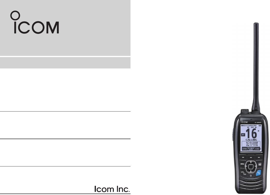
VHF MARINE TRANSCEIVER
iM93D EURO
iM93D

i
Thank you for choosing this Icom product.
This product is designed and built with Icom’ s state of the art
technology and craftsmanship. With proper care, this product
should provide you with years of trouble-free operation.
IMPORTANT
READ ALL INSTRUCTIONS carefully and completely
before using the transceiver.
SAVE THIS INSTRUCTION MANUAL—This instruction
manual contains important operating instructions for the
IC-M93D and IC-M93D EURO.
This instruction manual includes some functions which are
usable only when they are preset by your dealer.
Ask your dealer for details.
EXPLICIT DEFINITIONS
WORD DEFINITION
RDANGER! Personal death, serious injury or an explosion
may occur.
RWARNING! Personal injury, re hazard or electric shock
may occur.
CAUTION Equipment damage may occur.
NOTE
If disregarded, inconvenience only. No risk of
personal injury, re or electric shock.
FEATURES
zFloats on water
The transceiver oats in fresh or salt water even when the
supplied accessories are attached.
• It may sink when a third-party accessory is attached.
zFloats and ashes
When the transceiver detects that it has come in contact with
water, the backlight starts to blink, making it easy to nd the
transceiver even at night or in a dark environment.
zWide screen and easy user interface
The transceiver is equipped with a wide screen for easy
readability and easy-to-use user interface.
zDualwatch and Tri-watch functions
Convenient functions that enable you to monitor the Distress
channel (Ch 16) while receiving on another channel of your
choice (Dualwatch), or while receiving on another channel of
your choice, and the Call channel (Tri-watch).
* May not be usable depending on the transceiver version.
Icom is not responsible for the destruction, damage to, or
performance of any Icom or non-Icom equipment, if the
malfunction is because of:
• Force majeure, including, but not limited to, res,
earthquakes, storms, oods, lightning, other natural
disasters, disturbances, riots, war, or radioactive
contamination.
• The use of Icom transceivers with any equipment that is
not manufactured or approved by Icom.
ii
IN CASE OF EMERGENCY
If your vessel requires assistance, contact other vessels and
the Coast Guard by sending a distress call on Channel 16.
USING CHANNEL 16
DISTRESS CALL PROCEDURE
1. “MAYDAY MAYDAY MAYDAY.”
2. “THIS IS ...............” (name of vessel).
3. Say your call sign or other indication of the vessel
(AND your 9 digit DSC ID, if you have one).
4. “LOCATED AT ...............” (your position).
5. State the nature of the distress and assistance
required.
6. Give any other information which might facilitate
the rescue.
USING DIGITAL SELECTIVE CALLING (Ch 70)
DISTRESS CALL PROCEDURE
1. While lifting up the key cover, hold down
[DISTRESS] for 3 seconds until you hear 3 short
beeps and then one long beep.
2. Wait for an acknowledgment on Channel 70 from
a coast station.
• After the acknowledgement is received, Channel 16
is automatically selected.
3. Hold down [PTT], then transmit the appropriate
information as listed to the left.
Or, transmit your Distress call using Digital Selective Calling
(DSC) on Channel 70.
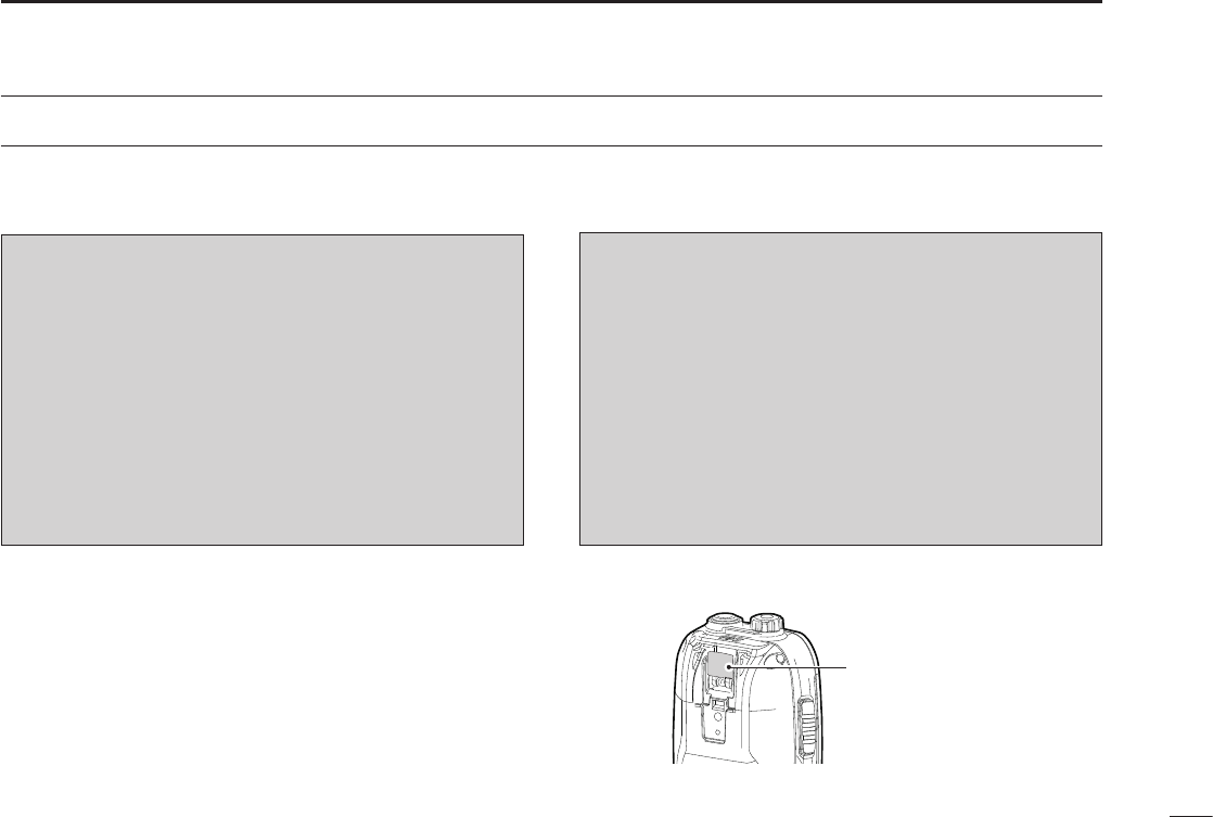
Key cover

iii
RDANGER! NEVER short the terminals of the battery
pack. Shorting may occur if the terminals touch metal
objects such as a key, so be careful when placing the
battery packs (or the transceiver) in bags, and so on. Carry
them so that shorting cannot occur with metal objects.
Shorting may damage not only the battery pack, but also the
transceiver.
RDANGER! NEVER operate the transceiver near
unshielded electrical blasting caps or in an explosive
atmosphere.
RDANGER! NEVER use and charge Icom battery packs
with non-Icom transceivers or non-Icom chargers. Only Icom
battery packs are tested and approved for use with Icom
transceivers or charged with Icom chargers. Using third-party
or counterfeit battery packs or chargers may cause smoke,
re, or cause the battery to burst.
RWARNING! NEVER operate the transceiver with a
headset or other audio accessories at high volume levels.
The continuous high volume operation may cause a ringing
in your ears. If you experience the ringing, reduce the
volume level or discontinue use.
CAUTION: DO NOT use harsh solvents such as Benzine
or alcohol when cleaning, because they will damage the
transceiver surfaces.
PRECAUTIONS
CAUTION: DO NOT attach the battery unless the exible
antenna, battery pack and jack cover are securely attached
to the transceiver. Conrm that the antenna and battery
pack are dry before attaching. Exposing the inside of the
transceiver to dust or water can cause serious damage to
the transceiver.
CAUTION: DO NOT place or leave the transceiver in direct
sunlight or in places with temperatures below –20°C (–4°F)
or above +60°C (+140°F) for IC-M93D, and below –15°C
(–10°C for the Australian version) or above +55°C for the
IC-M93D EURO. The basic operations of the transceiver
are guaranteed within the specied operating temperature
range. However, the Liquid Crystal Display may not operate
correctly, or show an indication in the case of long hours of
operation, or after being placed in extremely cold areas.
CAUTION: DO NOT modify the transceiver. The
specications may change and then the transceiver may not
comply with the requirements of required regulations. The
transceiver warranty does not cover any problems caused by
unauthorized modication.
CAUTION: DO NOT operate the transceiver if it becomes
hot after operating it continuously for long periods of time.
This may damage the transceiver.
KEEP the transceiver and microphone at least 0.9 m (3 feet)
away from the vessel’s magnetic navigation compass.

iv
PRECAUTIONS
DO NOT
push [PTT] unless you actually intend to transmit.
BE CAREFUL! The IC-M93D and IC-M93D EURO meet
IPX7* requirements for waterproof protection. However,
once the transceiver has been dropped, waterproof
protection cannot be guaranteed because of possible
damage to the transceiver’s case or the waterproof seal.
* Only when the speaker microphone jack cover, the
optional HM-165, or HM-228 is attached.
Even when the transceiver power is OFF, a slight current
still ows in the circuits. Remove the battery pack from the
trans ceiver when not using it for a long time. Otherwise, the
installed battery pack or batteries will become exhausted,
and will need to be recharged or replaced.
BE CAREFUL! Even if the volume level is set low, the
beeps of the Float ’n Flash, DSC alarm and AquaQuake
functions are very loud.
BE SURE the transceiver power is OFF before connect ing
the supplied or optional equipment.
Icom, Icom Inc. and the Icom logo are registered trademarks of Icom
Incorporated (Japan) in Japan, the United States, the United Kingdom, Germany,
France, Spain, Russia, Australia, New Zealand, and/or other countries.
RECOMMENDATION
CLEAN THE TRANSCEIVER THOROUGHLY WITH
FRESH WATER after exposure to saltwater, and dry
it before operating. Otherwise, the transceiver's keys,
switches and controllers may become unusable, due to salt
crystallization, and/or the charging terminals of the battery
pack may rust.
NOTE: DO NOT wash the transceiver in water if there
is any reason to suspect the waterproong may not be
effective. For example, in cases where the [SP MIC] jack
cover is damaged, the transceiver/battery pack is cracked
or broken, or has been dropped, or when the battery pack
is detached from the transceiver.

v
INFORMATION
FOR CLASS A UNINTENTIONAL RADIATORS
This equipment has been tested and found to comply with
the limits for a Class A digital device, pursuant to part 15
of the FCC Rules. These limits are designed to provide
reasonable protection against harmful interference when the
equipment is operated in a commercial environment. This
equipment generates, uses, and can radiate radio frequency
energy and, if not installed and used in accordance with the
instruction manual, may cause harmful interference to radio
communications. Operation of this equipment in a residential
area is likely to cause harmful interference in which case the
user will be required to correct the interference at his own
expense.
DISPOSAL
The crossed-out wheeled-bin symbol on your
product, literature, or packaging reminds you
that in the European Union, all electrical and
electronic products, batteries, and
accumulators (rechargeable batteries) must be
taken to designated collection locations at the
end of their working life. Do not dispose of
these products as unsorted municipal waste. Dispose of
them according to the laws in your area.
•List of Country codes (ISO 3166-1)
Country Codes Country Codes
1 Austria AT 18 Liechtenstein LI
2 Belgium BE 19 Lithuania LT
3 Bulgaria BG 20 Luxembourg LU
4 Croatia HR 21 Malta MT
5Czech Republic CZ 22 Netherlands NL
6 Cyprus CY 23 Norway NO
7 Denmark DK 24 Poland PL
8 Estonia EE 25 Portugal PT
9 Finland FI 26 Romania RO
10 France FR 27 Slovakia SK
11 Germany DE 28 Slovenia SI
12 Greece GR 29 Spain ES
13 Hungary HU 30 Sweden SE
14 Iceland IS 31 Switzerland CH
15 Ireland IE 32 Turkey TR
16 Italy IT 33 United Kingdom GB
17 Latvia LV
COUNTRY CODE LIST
CAUTION:
Changes or modications to this transceiver, not expressly
approved by Icom Inc., could void your authority to operate
this transceiver under FCC regulations.

vi
TABLE OF CONTENTS
IMPORTANT ............................................................................................... i
FEATURES .................................................................................................i
EXPLICIT DEFINITIONS ............................................................................ i
IN CASE OF EMERGENCY ...................................................................... ii
PRECAUTIONS ........................................................................................ iii
RECOMMENDATION ............................................................................... iv
INFORMATION ..........................................................................................v
DISPOSAL .................................................................................................v
COUNTRY CODE LIST ............................................................................. v
1. OPERATING RULES ........................................................................... 1
2. SUPPLIED ACCESSORIES AND ATTACHMENTS ........................2–3
■Supplied accessories ......................................................................2
■Attachments ....................................................................................2
3. PANEL DESCRIPTION .................................................................... 4–8
■Panel description ............................................................................. 4
■Display description ..........................................................................5
■Using the software keys ..................................................................7
■Software keys .................................................................................. 7
4. PREPARATIONS ...........................................................................9–10
■Entering the MMSI code .................................................................. 9
■Entering the ATIS ID (For Dutch and German versions) ...............10
5. PANEL DESCRIPTION ................................................................11–15
■Selecting a channel .......................................................................11
■Adjusting the volume level ............................................................13
■Adjusting the squelch level ............................................................ 13
■Setting the Call channel ................................................................13
■Receiving and transmitting ............................................................ 14
■Lock function .................................................................................14
■Monitor function ............................................................................. 15
■ AquaQuake Water Draining function .............................................15
■Editing a channel name ................................................................. 15
6. SCAN (Except for the Dutch version) ..........................................16–17
■Scan types ...................................................................................16
■Setting Favorite channels .............................................................. 17
■Starting a scan ..............................................................................17
7. DUALWATCH/TRI-WATCH (Except for the Dutch version) ............... 18
■Description ....................................................................................18
■Operation ......................................................................................18
8. DSC OPERATION .......................................................................19–44
■DSC address ID ............................................................................19
■Entering the position and time .......................................................21
■Sending DSC calls (Distress) ........................................................ 22
■Sending DSC calls (other) ............................................................. 25
■Receiving DSC calls (Distress) .....................................................34
■Receiving DSC calls (other) ..........................................................35
■DSC Log ........................................................................................ 40
■DSC Settings ................................................................................. 42
9. OTHER FUNCTIONS ..................................................................45–52
■MOB (Man OverBoard) .................................................................45
■Waypoint .......................................................................................46
■Navigation .....................................................................................48
■Compass .......................................................................................50
■GPS/GNSS ...................................................................................50
■Information screen ........................................................................52
10. MENU SCREEN ..........................................................................53–58
■Using the Menu screen .................................................................53
■Menu screen items ........................................................................ 54
■Radio Settings items .....................................................................55
■Conguration items .......................................................................57
11. BATTERY CHARGING ................................................................59–62
■Regular battery charger ................................................................61
■ Optional battery charger ................................................................62
12. OPTIONAL SPEAKER MICROPHONE ............................................63
■About the HM-165 .........................................................................63
■Attaching the HM-165 ...................................................................63
13. TROUBLESHOOTING ......................................................................64
14. SPECIFICATIONS AND OPTIONS .............................................65–67
■Specications ................................................................................65
■Options .......................................................................................... 67
15. CHANNEL LIST ...........................................................................68–70
16. SAFETY TRAINING INFORMATION ................................................71
INDEX ......................................................................................................72

1
1OPERATING RULES
DPriorities
• Read all rules and regulations pertaining to priorities and
keep an up-to-date copy handy. Safety and distress calls
take priority over all others.
• You must monitor Channel 16 when you are not operating
on another channel.
• False or fraudulent distress calls are prohibited under law.
DPrivacy
• Information overheard but not intended for you cannot
lawfully be used in any way.
• Indecent or profane language is prohibited.
DRadio licenses
(1) SHIP STATION LICENSE
You must have a current radio station license before using
the transceiver. It is unlawful to operate a ship station which
is not licensed.
Inquire through your dealer or the appropriate government
agency for a Ship-Radiotelephone license application. This
government-issued license states the call sign which is your
craft’s identication for radio purposes.
(2) OPERATOR’S LICENSE
A Restricted Radiotelephone Operator Permit is the license
most often held by small vessel radio operators when a
radio is not required for safety purposes.
The Restricted Radiotelephone Operator Permit must be
posted or kept with the operator. Only a licensed radio
operator may operate a transceiver.
However, non-licensed individuals may talk over a
transceiver if a licensed operator starts, supervises, ends
the call and makes the necessary log entries.
A current copy of the applicable government rules and
regulations is only required to be on hand for vessels in
which a radio telephone is compulsory. However, even
if you are not required to have these on hand it is your
responsibility to be thoroughly acquainted with all pertinent
rules and regulations.
NOTE: Even though the transceiver is capable of
operation on VHF marine channels 3, 21, 23, 61, 64,
81, 82 and 83, according to FCC regulations these
simplex channels cannot be lawfully used by the general
population in USA waters.
2
2
SUPPLIED ACCESSORIES AND ATTACHMENTS
1
2
3
4
5
6
7
8
9
10
11
12
13
14
15
16
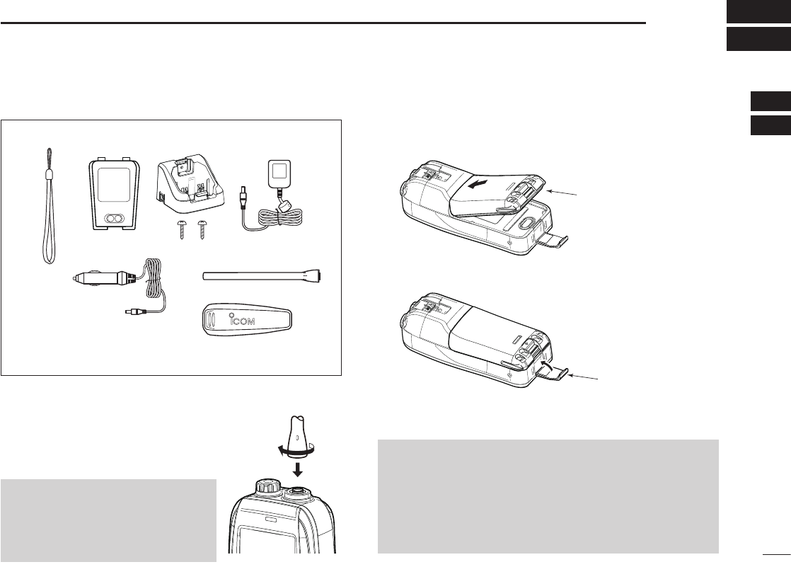
■Supplied accessories
■Attachments
DFlexible antenna
Connect the supplied antenna to the antenna
connector.
CAUTION:
• NEVER carry the transceiver by
holding the antenna.
• Transmitting without an antenna
may damage the transceiver.
Handstrap Battery pack Battery charger
(with 2 screws)
Power adapter*
Cigarette lighter cable*
Antenna
Belt clip
* May not be supplied, or different type may be supplied,
depending on the transceiver version.
DBattery pack
1. Attach the battery pack to the transceiver.
2. Lock the battery pack with the latch.
CAUTION: NEVER remove or attach the battery pack
when the transceiver is wet or soiled. This may result in
water or dust getting into the transceiver and battery pack,
and may result in them being damaged.
BE CAREFUL! The latch is tightly locked, so use caution
when releasing it. DO NOT use your ngernail. Use the
edge of a coin or screwdriver tip to carefully release it.
Battery pack
Latch
3
2SUPPLIED ACCESSORIES AND ATTACHMENTS
■Attachments (Continued)
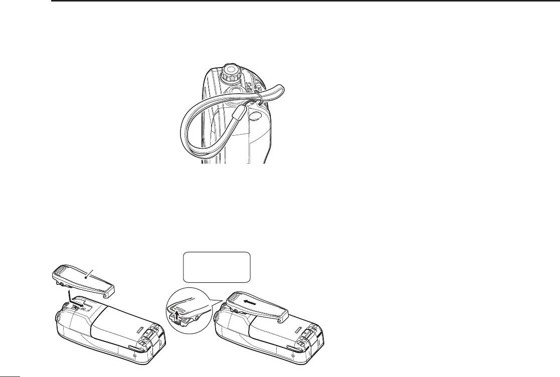
DHandstrap
Pass the handstrap through
the loop on the back side of
the transceiver to make it
easy to carry.
DBelt clip
Attach or detach the belt clip to/from the transceiver as
shown below.
w
q
Belt clip
To attach the belt clip To detach the belt clip
BE CAREFUL!
Do not break
your ngernail.
Lift the tab up q and slide the belt clip
in the direction of the arrow w.
4
3
PANEL DESCRIPTION
1
2
3
4
5
6
7
8
9
10
11
12
13
14
15
16
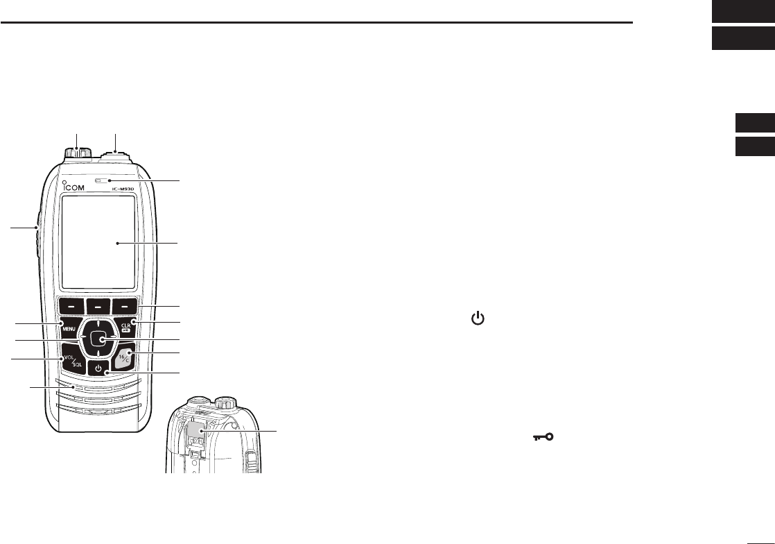
■Panel description
q
w
e
r
t
y
u
i
o
!0!1
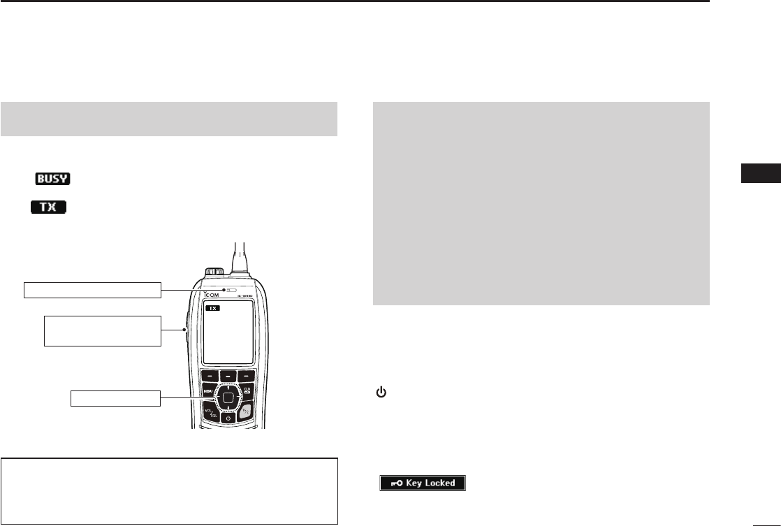
Microphone
q PTT SWITCH [PTT]
Hold down to transmit, release to receive.
w MENU KEY
Push to display or close the Menu screen.
Display
Distress
key (p. 25)
Speaker
e UP/DOWN/LEFT/RIGHT KEYS [▲]/[▼]/[◄]/[►]
z Push [▲] or [▼] to select the operating channel, Menu
items, Menu settings, and so on.
z Push [◄] or [►] to slide through the key functions that
are assigned to the software keys. (p. 7)
z Push to select the desired character or number in the
entry mode. (p. 9, 10, 15, 19, 21)
r VOLUME/SQUELCH KEY [VOL/SQL]
(p. 13)
z Push once to display the volume level setting screen.
z Push twice to display the squelch level setting screen.
z Hold down for 1 second to turn ON the Monitor
function. (p. 15)
t POWER KEY [ ]
Hold down for 1 second to turn the transceiver ON or OFF.
y CHANNEL 16 KEY [16/C]
zPush to select Channel 16. (p. 11)
z Hold down for 1 second to select the Call channel. (p. 11)
u ENTER KEY
Push to set the entered data, selected item, and so on.
i CLEAR/LOCK KEY [CLR/ ]
z Push to cancel the entered data, or to return to the
previous screen.
z Hold down for 1 second to turn the Key Lock function
ON or OFF. (p. 14)
5
3PANEL DESCRIPTION
■Panel description (Continued)
!0 ANTENNA CONNECTOR (p. 2)
Connects the supplied antenna.
!1
SPEAKER MICROPHONE JACK
(p. 63)
Connects the optional external speaker microphone.
NOTE: Attach the jack cover when the optional speaker
microphone is not used. Otherwise, water will get into
the transceiver.
o
!0!1
o SOFTWARE KEYS
Slide through the key
functions by pushing [◄]
or [►], and then push
either of the 3 software
keys to select the function
displayed at the bottom of
the display.
See “Software keys” on
page 7 for details.
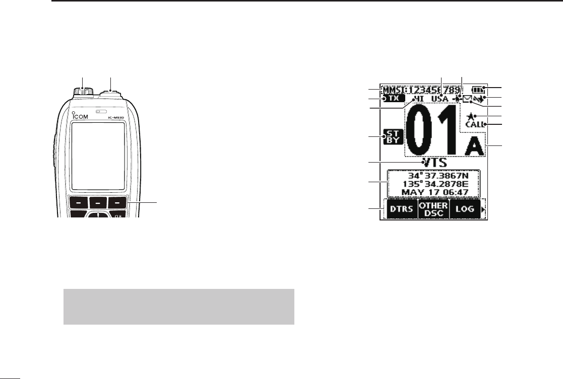
■Display description
r
t
y
!5
q
u
!0
!1
!4
w
e
!2
!3
i
o
q MMSI CODE DISPLAY (p. 9)
Displays the entered MMSI code.
w STATUS ICON (p. 14)
• “TX” is displayed while transmitting.
• “MONI”
is displayed
while the Monitor function is
activated.
• “BUSY” is displayed while receiving, or when the
squelch is open.
e POWER INDICATOR (p. 8)
• “HI” is displayed when high power is selected.
• “LOW” is displayed when low power is selected.
6
3
PANEL DESCRIPTION
1
2
3
4
5
6
7
8
9
10
11
12
13
14
15
16
r STATUS ICON
• “STBY” is displayed while not receiving nor transmitting.
• “RT” (Radio Telephone mode) is displayed while
receiving or transmitting a signal or when the squelch
opens. (p. 13, 56)
• “DSC” is displayed while in the DSC mode.
t CHANNEL NAME
• The channel name is displayed, if entered. (p. 15)
• “SCAN” or “SCAN 16” is displayed while scanning. (p. 16)
• “DUAL 16” or “TRI 16”
is displayed
while using the
Dualwatch or Tri-watch function. (p. 18)
y POSITION/TIME INDICATOR
Displays the current position and time when valid GPS
data is received, or when manually entered.
Received GPS data:
• “??” blinks if no GPS data is received for 30 seconds after
receiving valid GPS data, and then “??” and a warning message
are displayed alternately after 10 minutes.
• A warning message is displayed if no GPS data is received for 4
hours after receiving valid GPS data.
• “No Position No Time” is displayed if no GPS data is received
for 2 minutes after turning ON the transceiver, and then a
warning message is displayed.
L “Local” is displayed when the UTC Offset time is set. (p. 21)
Manually entered GPS data:
• A manually entered GPS data is valid for 4 hours, and then a
warning message is displayed after 4 hours.
L
“Manual” is displayed.
u SOFTWARE KEY FUNCTION DISPLAY (p. 7, p. 14)
• The software key functions are displayed.
• “Key Locked” is displayed while the Lock function is ON.
i CHANNEL NUMBER READOUT
Displays the selected operating channel number.
L“A” is displayed when a simplex channel is selected.
o CALL CHANNEL ICON (p. 11)
Displayed when a Call channel is selected.
!0 FAVORITE CHANNEL ICON (p. 17)
Displayed when a Favorite channel is selected.
!1 MAIL ICON (p. 40)
• Displayed when there is an unread message.
• Blinks until one of the call messages is read.
!2 DSC SWITCH ICON (p. 42)
• Displayed when the “CH Auto Switch” is set to “Ignore”
or “Manual”
• Blinks when the “DSC Switch” is OFF.
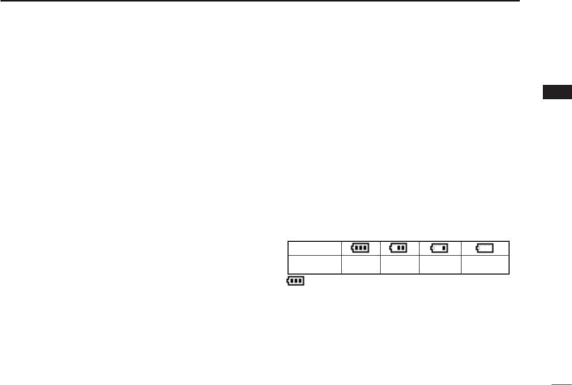
!3 BATTERY INDICATOR
Displays the battery’s remaining power.
!4 GPS ICON
• Stays ON while valid GPS position data is received.
• Blinks while no position data is received.
!5
CHANNEL GROUP ICON
• The selected Channel Group’s icon is displayed.
• “WX”
is displayed
for the Weather channel in the USA,
Australian, and Export versions.
(p. 12)
blinks when the battery is overcharged (or over voltage)
Indication
Battery level Full Mid Charging
required
Battery
exhausted
7
3PANEL DESCRIPTION
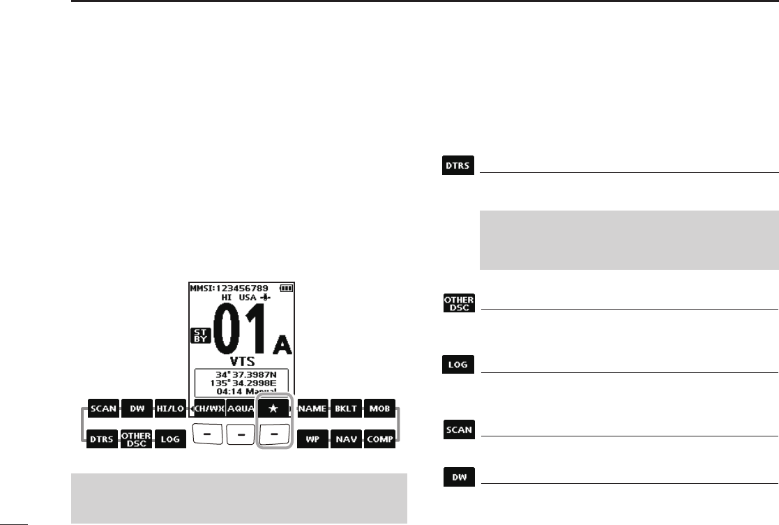
■Software keys
You can assign the following functions to the software keys
on the Menu screen.
■Using the software keys
Various often-used functions are assigned to the software
keys for easy access. The functions’ icons are displayed
above the software keys, as shown below.
DSelecting a software key function
1. Push[◄]or[►]toslidethroughtheselectable
functions that are assigned to the software keys.
2. Push the software key under the function’s icon to
select the function.
(Example: Selecting a Favorite channel)
NOTE: The displayed icons, or their order, may differ,
depending on the transceiver version or the presetting. Ask
your dealer for presetting details.
Distress Call (p. 22)
Push to display the “Distress Call” screen to select
the nature of the call, and then to make a call.
Push[◄] Push[►]
Other DSC (p. 25)
Push to compose an Individual Call, Group Call, All
Ships Call, or a Test Call.
LOG (p. 40)
Push to display the received call log or distress
message log.
Scan (p. 16)
Push to start or stop a Normal or Priority scan.
Dualwatch/Tri-watch (p. 18)
Push to start or stop Dualwatch or Tri-watch.
NEVER MAKE A DISTRESS CALL IF YOUR SHIP OR
A PERSON IS NOT IN AN EMERGENCY. A DISTRESS
CALL SHOULD BE MADE ONLY WHEN IMMEDIATE
HELP IS NEEDED.

8
3
PANEL DESCRIPTION
1
2
3
4
5
6
7
8
9
10
11
12
13
14
15
16
High/Low (p. 5)
Push to set the power to high or low.
LSome channels are set to only low power.
Channel/Weather channel (p. 11~12)
Push to select regular channels or Weather* channels.
L is displayed except for the USA, Australian, and
Export versions.
L While the Call channel or Channel 16 is displayed, push
this key to return to the regular channel mode.
* The Weather channels are for only the USA, Australian,
and Export versions.
AquaQuake (p. 15)
Hold down to turn ON the AquaQuake function to
clear water from the speaker grill.
Favorite channel (p. 17)
z Push to select a Favorite channel.
z Hold down for 1 second to set the displayed
channel as a Favorite channel.
z While a Favorite channel is displayed, hold down
for 1 second to clear the Favorite channel setting.
Channel Name (p. 15)
Push to edit the name of the displayed channel.
Backlight (p. 57)
Push to display the backlight brightness adjustment
screen.
LWhileintheadjustmentmode,push[▲]/[▼][◄]/[►]to
adjust the brightness to between 1 and 7, or OFF.
MOB (p. 45)
zPush to display the “MOB” screen.
z Hold down for 1 second to memorize the current
position as the Man OverBoard (MOB) waypoint.
Waypoint (p. 46)
zPush to display the “Waypoint” screen.
z
Hold down for 1 second to memorize the current
position as a Waypoint.
Navigation (p. 48)
While displaying the “MOB” or “Waypoint” screen,
push this key to start navigating to the selected
position.
Compass (p. 50)
Push to display the “Compass” screen to check the
vessel’s course heading, Speed Over Ground (SOG)
and Course Over Ground (COG).
9
4PREPARATIONS
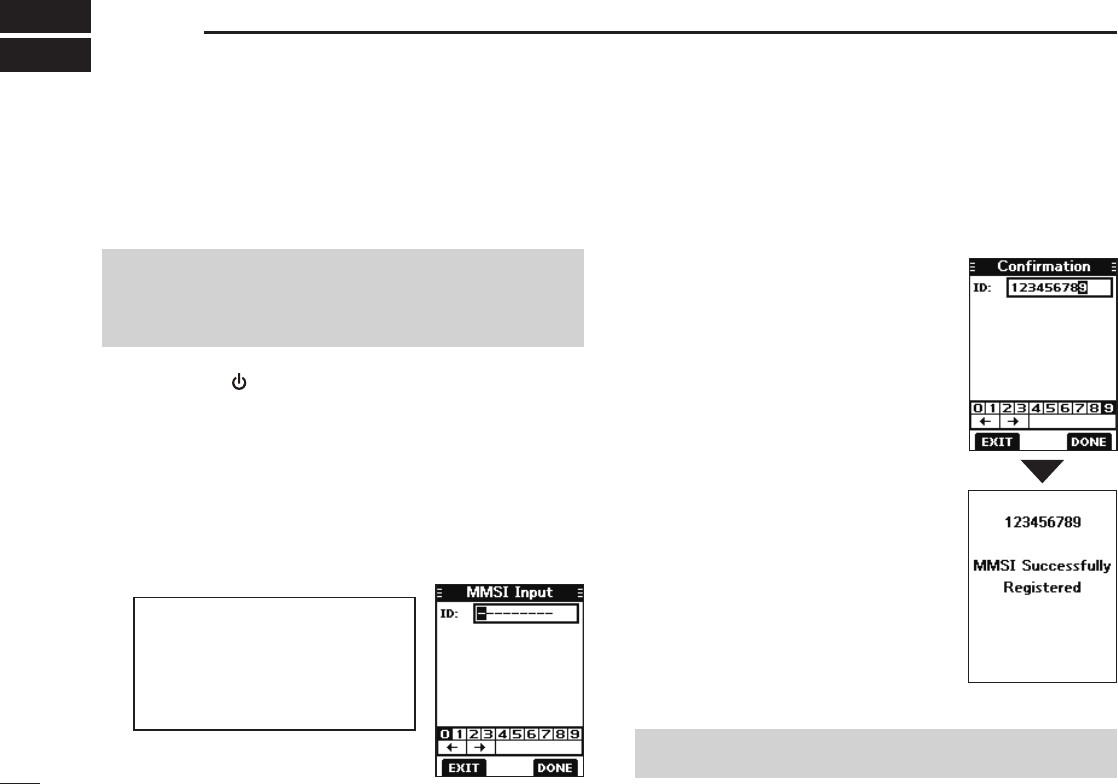
■Entering the MMSI code
The Maritime Mobile Service Identity (MMSI: DSC self ID)
code consists of 9 digits. You can only enter the code when
turning ON the transceiver for the rst time.
4. Repeat step 3 to enter all 9 digits.
5. Push the software key below [DONE] to set the entered
code.
• The “Conrmation” screen is displayed.
This initial code entry can be done only once.
After entering, it can be changed only by your dealer
or distributor. If your MMSI code has already been
entered, this entry is not necessary.
1. Hold down [ ] to turn ON the transceiver.
• Three short beeps sound, and “Push [ENT] to Register your
MMSI” is displayed.
2. Push [ENT] to start entering the MMSI code.
• The “MMSI Input” screen is displayed.
L Push [CLR] twice to skip the entry.
If you skip the entry, you cannot make a DSC call. To enter
the code after skipping, turn OFF the power, and then turn it
ON again.
3. Enter the MMSI code.
TIP:
• Select a number using [◄] and [►].
• Push [ENT] to enter the selected
number.
• Select “←” or “→,” to move the
cursor.
NOTE: For the Dutch and German versions, entering the
ATIS ID is also required. See the next page for details.
6. Enter your MMSI code again to
confirm.
7. Push the software key below
[DONE] to set the entered code.
L When your MMSI code is successfully
entered, “MMSI Successfully
Registered” is briey displayed, and
then the operating screen opens.
L Your MMSI code is also displayed on
the operating screen.
10
4
PREPARATIONS
1
2
3
4
5
6
7
8
9
10
11
12
13
14
15
16
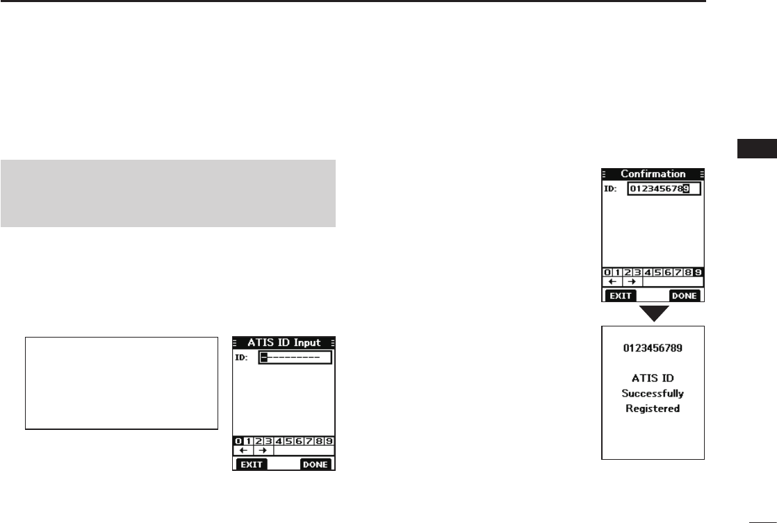
The Automatic Transmitter Identification System (ATIS) ID
consists of 10 digits. You can enter the ID in the “ATIS ID
Input” item on the Menu screen.
■Entering the ATIS ID (For Dutch and German versions)
This ID entering can be done only once. After entering,
it can be changed only by your dealer or distributor.
If your ATIS ID has already been entered, this entry is
not necessary.
1. Push [MENU].
• The Menu screen is displayed.
2. Push [▲] or [▼] to select “ATIS ID Input,” and then push
[ENT] to start entering.
• The “ATIS ID Input” screen is displayed.
3. Enter your ATIS ID.
TIP:
• Select a number using [◄] and [►].
• Push [ENT] to enter the selected
number.
• Select “←” or “→,” to move the
cursor.
4. Repeat step 3 to enter all 10 digits.
5. Push the software key below [DONE] to set the entered
ID.
• The “Conrmation” screen is displayed.
6. Enter your ATIS ID again to
confirm.
7. Push the software key below
[DONE] to set the entered ID.
L When your ATIS ID is successfully
entered, the screen displays “ATIS
ID Successfully Registered,” and
then the operating screen opens.
L You can check the ATIS ID in
“Information” on the Menu screen.
11
5BASIC OPERATIONS
■Selecting a channel
NOTE: Before using the transceiver for the first time, the
battery pack must be fully charged for optimum life and
operation. To avoid damage to the transceiver, turn OFF
the transceiver before charging.
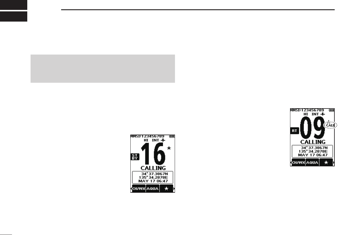
DChannel 16
Channel 16 is the distress and safety channel. It is used to
establish the initial contact with a station and for emergency
communications. Channel 16 is monitored during both
Dualwatch and Tri-watch. While in the standby mode, you
must monitor Channel 16.
Push [16/C] to select Channel 16.
L To return to the previously selected
channel, push the software key below
[CHAN] or [CH/WX].
DCall channel
Each Channel Group has separate leisure-use Call
channels. The Call channel is monitored during Tri-watch.
The Call channels can be selected and used to store your
most often used channel in each Channel Group, for quick
recall.
LSee page 13 for details on setting the Call channel.
Hold down [16/C] for 1 second to
select the Call channel.
• The Call channel number and “CALL” are
displayed.
L To return to the previously selected
channel, push the software key below
[CHAN] or [CH/WX].
12
5
BASIC OPERATIONS
1
2
3
4
5
6
7
8
9
10
11
12
13
14
15
16
DSelecting a Channel Group
Channel Groups are preset into your transceiver. You can select
the Channel Group between USA, International, Canadian,
DSC, and ATIS depending on the transceiver version.
Version Preset Channel Group
USA INT CAN DSC ATIS
USA
UK
European
Dutch
German
Australian
Export (Other)
1. Push [MENU].
• The Menu screen is displayed.
2. Push [▲] or [▼] to select “Radio
Settings,” and then push [ENT].
• The “Radio Settings” screen is
displayed.
3. Push [▲] or [▼] to select “CHAN
Group,” and then push [ENT].
• The “CHAN Group” screen is
displayed.
4.
Push [▲] or [▼] to select the
Channel Group, and then push
[ENT].
L Select [EXIT] to exit the Menu
screen.
L The selected Channel Group’s icon
is displayed on the operating screen.
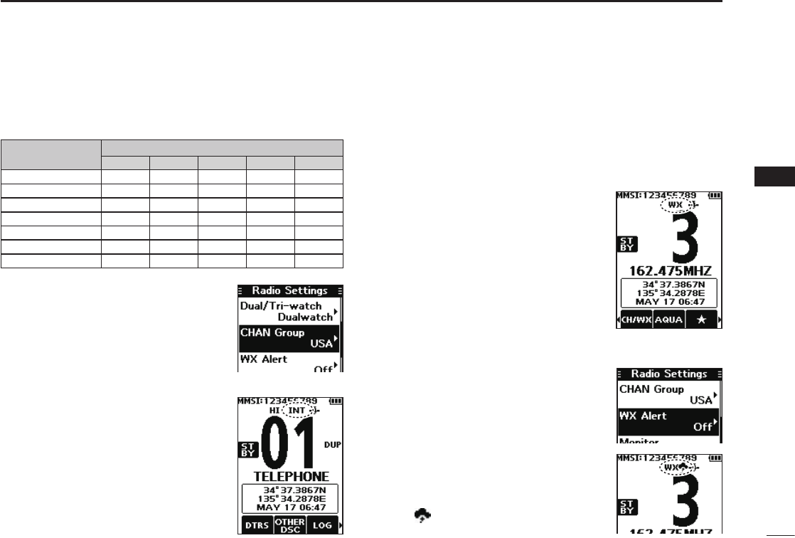
DWeather channels and Weather Alert
For the USA, Australian, and Export versions, the
transceiver has 10 preset Weather channels. You can use
these channels to monitor broadcasts from the National
Oceanographic and Atmospheric Administration (NOAA).
The transceiver automatically detects a Weather alert tone
on the selected weather channel, or while scanning.
Selecting a Weather channel
1. Push the software key below
[CH/WX] on the software key.
• “WX” is displayed on the operating
screen instead of the Channel Group
icon.
2. Push [▲] or [▼] to select a
Weather channel.
Setting the Weather Alert
LSee page 55 for details on the Weather Alert function.
1. Push [MENU].
2. Push [▲] or [▼] to select “Radio
Settings,” and then push [ENT].
• The “Radio Settings” screen is
displayed.
3. Select “WX Alert,” and then push
[ENT].
• The “WX Alert” screen is displayed.
4. Select “On with Scan” or “On.”
• “ ” is displayed next to the weather
channel icon.
13
5BASIC OPERATION
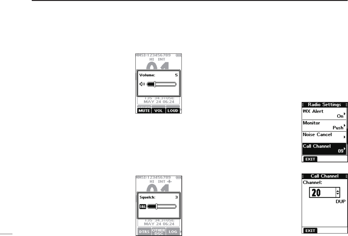
■Setting the Call channel
By default, a Call channel is set in each Channel Group.
You can set your most often-used channel as your Call
channel in each Channel Group for a quick recall.
1. Push [MENU].
• The Menu screen is displayed.
2. Push [▲] or [▼] to select “Radio Settings,” and then
push [ENT].
• The “Radio Settings” screen is
displayed.
4. Push [▲] or [▼] to select the
channel.
5. Push [ENT] to set the selected
channel as the Call channel.
L Push the software key below
[EXIT] to return to the operating
screen.
■Adjusting the volume level
1. Push [VOL/SQL].
• The volume level adjustment screen is
displayed.
2. Push [◄] or [►] to adjust the volume
level between 1 and 20, or OFF.
L You can also push the software key
below [MUTE] to select OFF, or below
[LOUD] to set the maximum volume
level.
L If no key is pushed for 5 seconds, the
screen automatically closes.
3. Push [ENT] to set.
■Adjusting the squelch level
Squelch enables the audio to be heard only while receiving a
signal that is stronger than the set level. A higher level blocks
weak signals, which enables you to receive only stronger
signals. A lower level enables you to hear weak signals.
1. Push [VOL/SQL] twice.
• The squelch level adjustment screen is
displayed.
2. Push [◄] or [►] to adjust the
volume level between 1 and 10, or
Open.
L If no key is pushed for 5 seconds, the
adjustment screen automatically closes.
3. Push [ENT] to set.
3. Push [▲] or [▼] to select “Call
Channel,” and then push [ENT].
• The “Call Channel” screen and the
default Call channel is displayed.
14
5
BASIC OPERATION
1
2
3
4
5
6
7
8
9
10
11
12
13
14
15
16
■Receiving and transmitting
CAUTION: Transmitting without an antenna may damage
the transceiver.
1. Push [▲] or [▼] to select the channel to call.
L You cannot transmit on Channel 70.
L is displayed while receiving a signal.
2. Hold down [PTT] and speak into the microphone.
• is displayed while transmitting.
3. Release [PTT] to receive.
Hold down to transmit.
Release to receive.
Select a channel.
Speak into the microphone
TIP: To maximize the readability of your transmitted signal,
pause for a second after pushing [PTT] and hold the
microphone 5 to 10 cm (2 to 4 inches) from your mouth,
and then speak at your normal voice level.
NOTE:
• To conserve battery power, the Power Save function
automatically turns ON when no signal is received for 5
seconds.
• When the temperature is extremely high, the battery
protection function automatically sets transceiver power
to Low, and disables High power selection.
• Except for the Export version, the Time-out Timer function
cuts OFF transmission after 5 minutes of continuously
transmitting, to prevent prolonged transmission.
• The Noise Cancel function reduces random noise
components in the transmit and/or received signal.
See page 56 for details.
■Lock function
The Lock function electronically locks all keys except for
[], [PTT], and [DISTRESS]. This function enables you to
prevent accidentally changing the channel, or accessing the
functions.
Hold down [CLR é] for 1 second to turn the Lock function
ON or OFF.
• is displayed on the bottom of the display while
the Lock function is ON.
15
5BASIC OPERATION
■Monitor function
The Monitor function temporarily cancels the Squelch
function to check for weak signals.
1. Hold down [VOL/SQL] to turn ON the Monitor function.
L
The Monitor function is ON while [VOL/SQL] is held down.
• is displayed.
• If there is a weak signal, you can hear the signal and noise.
2. Release to turn OFF.
TIP: You can change the Monitor function settings. See
page 55 for details.
■ AquaQuake Water Draining
function
Water in the speaker grill may mufe the sound coming
from the speaker. The AquaQuake Water Draining function
removes water from the speaker grill by vibrating the speaker.
1. Push [◄] or [►] to select .
2. Hold down the software key below to turn ON the
function.
• A low frequency vibration beep sounds to drain the water,
regardless of the volume level setting.
L This function is activated for a maximum of 10 seconds,
even if you continue to hold down the software key.
3. Release the key to turn OFF the function.
NOTE: You cannot use this function when an external speaker
microphone is connected.
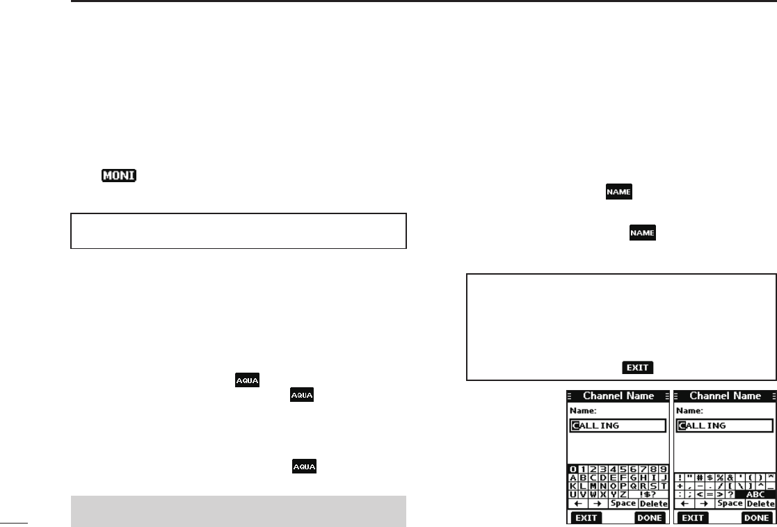
■Editing a channel name
You can edit the name of each operating channel and weather
channel, using numbers, uppercase letters, symbols, and
a space. This enables easy recognition of the channels or
stations. All VHF marine channels are set with default names.
1. Push [▲] or [▼] to select the channel to edit.
2. Push [◄] or [►] to select .
L You cannot edit a channel name during Dualwatch, Tri-watch,
or a Scan.
3. Push the software key below .
• The “Channel Name” screen is displayed.
4. Edit the channel name.
TIP:
• Select [! $ ?] to enter characters, and select [ABC] to enter
numbers and letters.
• Select characters or space using [▲]/[▼]/[◄]/[►].
• Push [ENT] to enter the selected character.
• Select “←” or “→,” to move the cursor.
• Push the software key below to cancel editing.
5. Push the
software key
below [DONE]
to set the edited
name.
16
6
SCAN (Exept for the Dutch version)
1
2
3
4
5
6
7
8
9
10
11
12
13
14
15
16
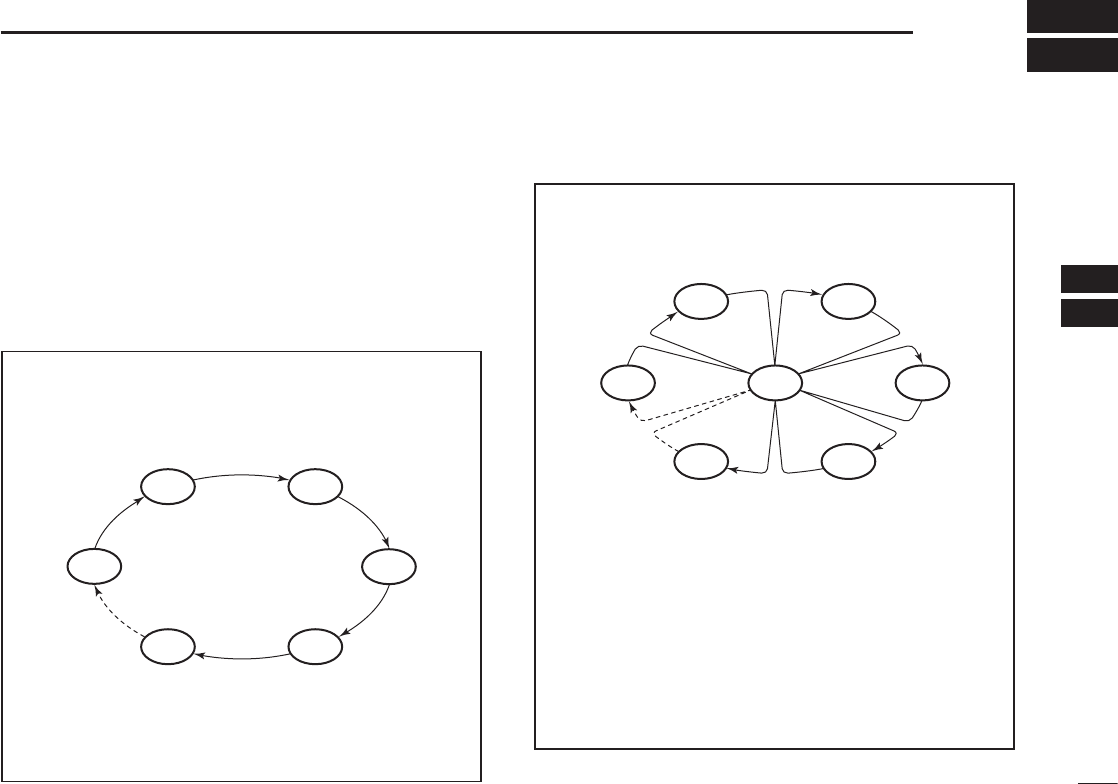
■Scan types
You can nd ongoing calls by scanning the Favorite channels.
Before starting a scan, you need to:
• Set the channels that you want to scan as Favorite
channels. (p. 17)
LOnly the Favorite channels are scanned.
• Set the scan type to “Priority Scan” or “Normal Scan” on
the “Radio Settings” screen. (p. 55)
WX*
CH 01
CH 16
CH 02
CH 05 CH 04
CH 03
Priority Scan
The Priority Scan sequentially searches through all
Favorite channels, while also monitoring Channel 16.
When a signal is received:
On Channel 16
The scan pauses until the signal disappears.
On a channel other than Channel 16
The scan becomes Dualwatch until the signal
disappears.
*For USA, Australian, and Export versions.
When the Weather Alert function is ON, the
previously selected Weather channel is also
scanned.
CH 01 CH 02
WX*
CH 05 CH 04
CH 03
Normal Scan
The Normal Scan sequentially searches through
all Favorite channels. However, Channel 16 is not
checked unless it is set as a Favorite channel.
*For USA, Australian, and Export versions.
When the Weather Alert function is ON, the
previously selected Weather channel is also
scanned.
17
6SCAN (Except for the Dutch version)
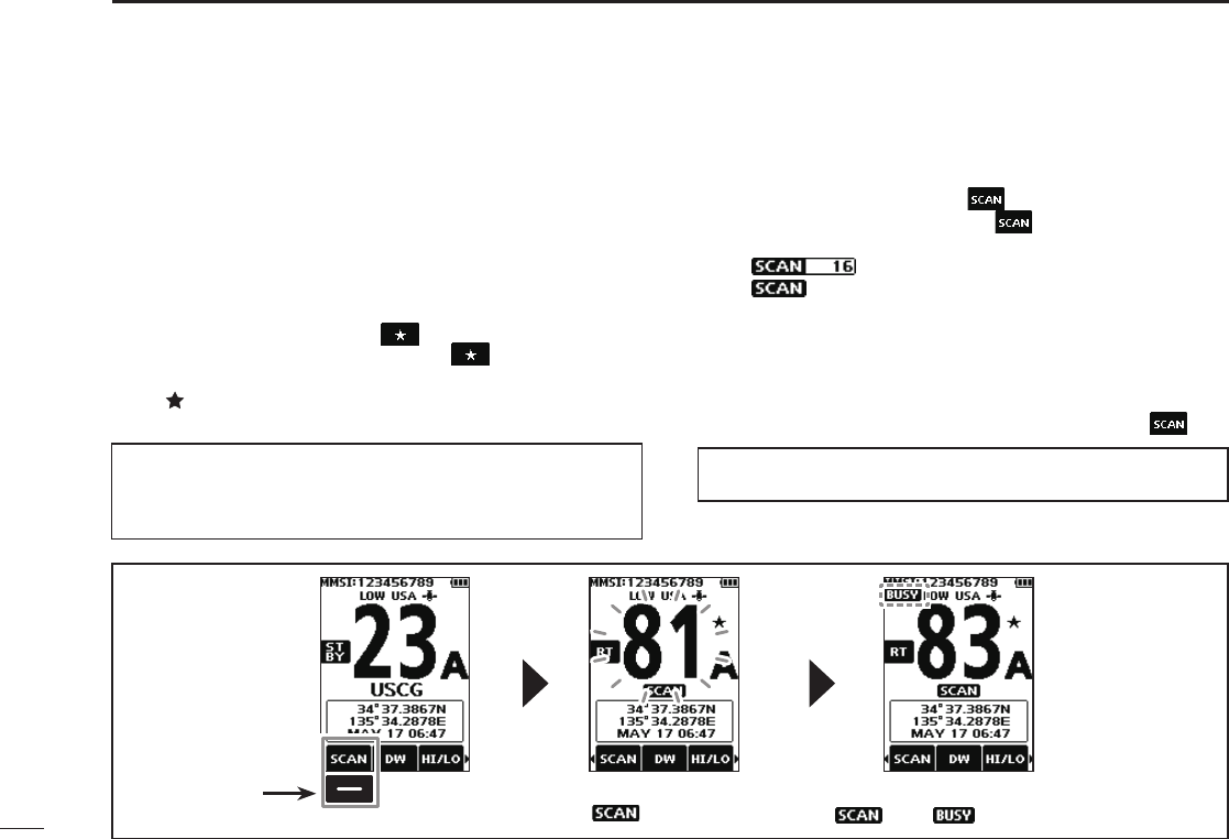
■Starting a scan
1. Select a Channel Group. (p. 12)
2. Push [◄] or [►] to display .
3. Push the software key below .
• The scan starts.
• “ ” is displayed during a Priority Scan, and
“ ” is displayed during a Normal Scan.
L When a signal is received, the scan pauses until the signal
disappears, or resumes after 5 seconds, depending on the
Scan Timer setting in “Radio Settings.”
L A beep sounds and “16” blinks when a signal is received on
Channel 16 during a Priority scan.
4. To stop the scan, push the software key below .
■Setting Favorite channels
You can quickly recall often-used channels by setting them
as Favorite channels. You can set Favorite channels in each
Channel Group.
1. Select a Channel Group. (p. 12)
2. Push [▲] or [▼] to select the channel you want to set as
a Favorite channel.
3. Push [◄] or [►] to display .
4. Hold down the software key below for 1 second.
• The selected channel is set as a Favorite channel, and
“ ” is displayed.
LTo cancel the setting, hold down the key again for 1 second.
TIP: You can set all channels as Favorite channels, clear all
settings, or reset to the default. By default, some channels
are preset as Favorite channels. The preset channels differ,
depending on the transceiver version.
TIP: In order to properly receive signals, be sure to adjust the
squelch to a suitable level.
Example: Starting a
Normal Scan
Push to start When a signal is received
“ ” and “ ” are displayed.
While scanning
“” is displayed.
18
7
DUALWATCH/TRI-WATCH (Except for the Dutch version)
1
2
3
4
5
6
7
8
9
10
11
12
13
14
15
16
■Description
Dualwatch and Tri-watch are convenient to monitor Channel
16 while you are operating on another channel.
When a signal is received:
On Channel 16
Dualwatch/Tri-watch pauses on Channel 16 until the
signal disappears.
On the Call channel
Tri-watch switches to Dualwatch until the signal on the
Call channel disappears.
Ch 88
Ch 16
Ch 88
Ch 16
Ch 9
Normal channel
Call
channel
Normal
channel
Monitors Channel 16
while receiving on another
channel.
Monitors Channel 16 and the
Call channel while receiving
on another channel.
Dualwatch Tri-watch
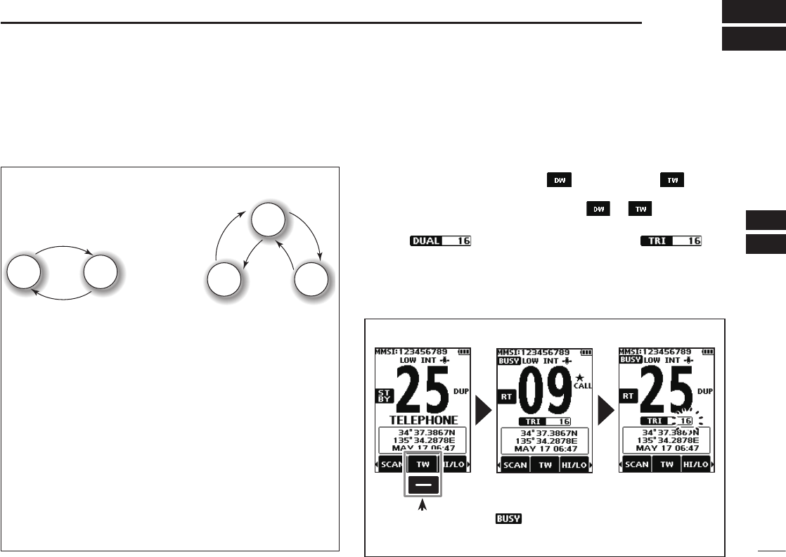
■Operation
1. Select Dualwatch or Tri-watch in “Radio Settings.”
(p. 55)
2. Push [▲] or [▼] to select a channel.
3. Push [◄] or [►] to display (Dualwatch) or
(Tri-watch).
4. Push the software key below the or .
• Dualwatch or Tri-watch starts.
• “ ” is displayed for Dualwatch, and “ ”
is displayed for Tri-watch.
LBeeps sound when a signal is received on Channel 16.
5. To cancel Dualwatch or Tri-watch, push the software
key again.
Example: Operating Tri-watch on INT Channel 25.
Push to start
Signal is received on
the Call channel.
“ ” is displayed.
Signal received on
Channel 16 takes
priority. “16” blinks.
LTri-watch resumes after the signal disappears.
19
New2001
DSC OPERATION
8
■DSC address ID
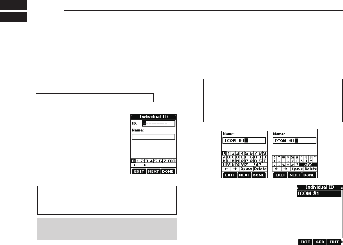
DEntering an Individual ID
You can enter a total of 75 Individual IDs, and assign names
of up to 10 characters.
1. Display the “Individual ID” screen.
[MENU] ► “DSC Settings” ► “Individual ID”
• “No ID” is displayed if no ID is entered.
TIP:
• Select a number using [◄] and [►].
• Push [ENT] to enter the selected number.
• Select “←” or “→,” to move the cursor.
TIP:
• Select [! $ ?] to use characters, and select [ABC] to use
numbers and letters.
• Select characters or space using [▲]/[▼]/[◄]/[►].
• Push [ENT] to enter the selected character.
• Select “←” or “→,” to move the cursor.
2. Push the software key below
[ADD].
• The Individual ID’s entry screen is
displayed.
3. Enter the Individual ID.
4. Push the software key below [NEXT] to start entering
the name.
NOTE: the rst digit is xed as “0” for a Group ID.
The rst two digits are xed as “0” for any Coast
station ID.
5. After entering, push the software
key below [DONE] to save, and
return to the previous screen.
• The entered name is displayed.
20
8
DSC OPERATION
New2001
1
2
3
4
5
6
7
8
9
10
11
12
13
14
15
16
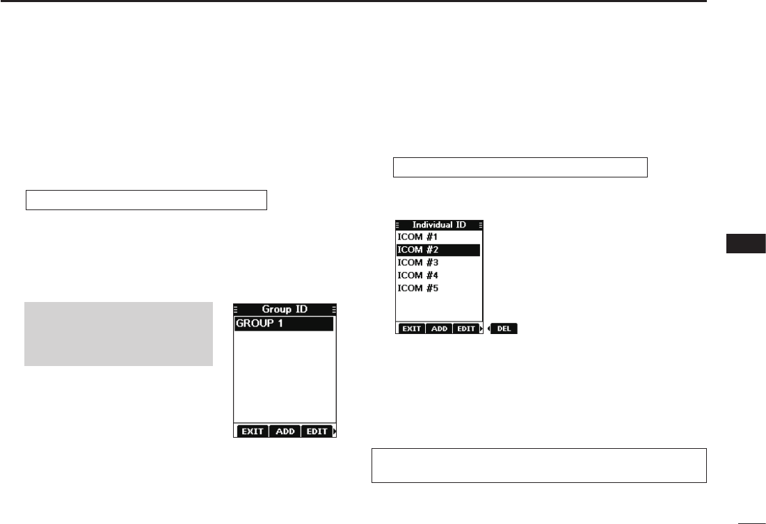
DEntering a Group ID
You can enter a total of 25 Group IDs, and assign names of
up to 10 characters.
1. Display the “Group ID” screen.
[MENU] ► “DSC Settings” ► “Group ID”
• “No ID” is displayed if no ID is entered.
2. Push the software key below [ADD].
• The Group ID’s entry screen is displayed.
3. Enter the Group ID and its name in the same way as
described on the previous page.
4. After entering, push the software
key below [DONE] to save, and
return to the previous screen.
• The entered name is displayed.
NOTE: The rst digit is xed as
“0” for a Group ID.
The rst two digits are xed as
“0” for any Coast station ID.
DDeleting an Individual ID or Group ID
[Example: Deleting an Individual ID: ICOM #2]
1. Display the “Individual ID” screen.
[MENU] ► “DSC Settings” ► “Individual ID”
2. Push [▲] or [▼] to select “ICOM #2.”
3. Push [►] to display [DEL].
4. Push the software key below [DEL].
• “Are you sure?” is displayed.
5. Push the software key below [OK] to delete.
L Push the software key below [CANCEL] to cancel the
deletion.
• The selected ID is deleted, and then returns to the previous
screen.
TIP: You can edit an ID and its name by pushing the
software key below [EDIT] in step 3.
21
8DSC OPERATION
New2001
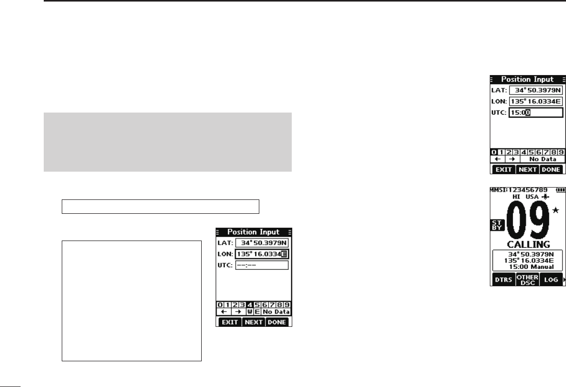
■Entering the position and time
A Distress call should include the vessel’s position and time.
If no GPS data is received, manually enter the position and
Universal Time Coordinated (UTC) time.
[MENU] ► “DSC Settings” ► “Position Input”
NOTE:
• The manual entry is disabled while the GPS data is
received.
• The manually entered position and time is valid only for 4
hours, or until turning OFF the transceiver.
1. Display the “Position Input” screen.
2. Enter the latitude and longitude.
TIP:
• Select a number or a compass
direction using [▲]/[▼]/[◄]/[►].
• Push [ENT] to enter the selected
number.
• Select “←” or “→,” to move the
cursor.
• Push the software key below
[NEXT] to change the entry
between latitude, longitude, and
UTC.
3. Push the software key below
[NEXT] to start entering the UTC
time.
L Use the TIP in step 2 to enter.
4. Push the software key below
[DONE] to set the entered
position and time.
• Returns to the previous screen.
L The entered position and time are
displayed on the operating screen.
L “Manual” is displayed next to the
time display.
22
8
DSC OPERATION
New2001
1
2
3
4
5
6
7
8
9
10
11
12
13
14
15
16
■Sending DSC calls (Distress)
A Distress call should be sent if, in the opinion of the Master,
the ship or a person is in distress and requires immediate
assistance.
NEVER MAKE A DISTRESS CALL IF YOUR SHIP OR A PERSON
IS NOT IN AN EMERGENCY. A DISTRESS CALL SHOULD BE
MADE ONLY WHEN IMMEDIATE HELP IS NEEDED.
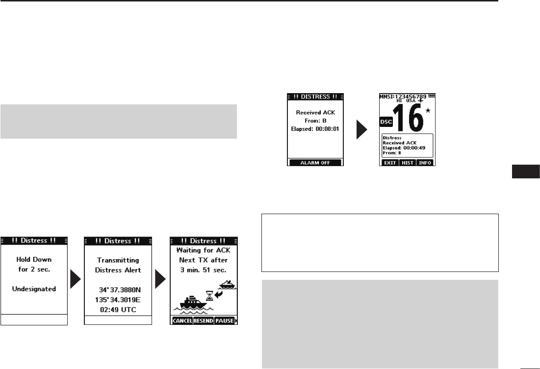
DSimple call
1. Confirm that no Distress call is being received.
2. While lifting up the key cover, hold down [DISTRESS]
for 3 seconds until you hear 3 short countdown beeps
and a long beep sound.
• The backlight blinks.
3. After sending, wait for an Acknowledgement call.
• “Waiting for ACK” is displayed.
4. Push any software key to turn OFF the alarm.
• Channel 16 is automatically selected.
5. Hold down [PTT] to explain your situation.
6. Push the software key below [EXIT] to return to the
operating screen.
TIP: A default Distress alert contains:
• Nature of distress: Undesignated distress
• Position information: The latest GPS, or manually input
position, which is held for 4 hours or until turning OFF the
transceiver.
NOTE on Distress calls (Simple calls and Regular calls):
If no valid position data is received when sending a
Distress call, the transceiver waits for 15 seconds until
position data is received, and then the Distress call is
sent. If no position is received during this 15 seconds, the
position data in the transceiver memory is automatically
sent. However, if there is no position data in the memory,
the Distress call is sent without position data.
L The Distress call is automatically sent every 3.5 to 4.5
minutes, until an Acknowledgement is received, or a Distress
Cancel call is sent. (p. 24)
L When you receive an Acknowledgement, alarm sounds.
23
8DSC OPERATION
New2001
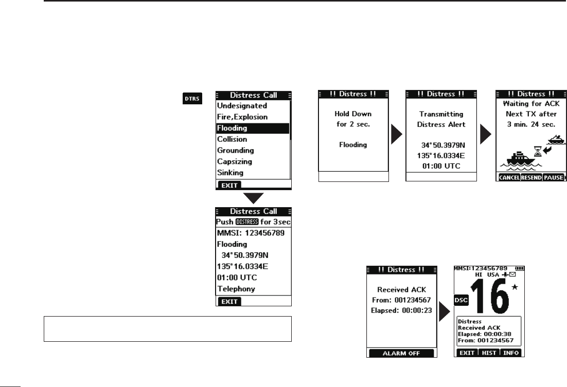
DRegular call
Select the nature of the Distress call to include in the
Regular Distress call.
1. Push the software key below .
• The “Distress Call” screen is displayed.
2. Push [▲] or [▼] to select the nature
of the call, and then push [ENT].
(Example: Flooding)
• The conrmation screen is displayed.
L If no valid GPS data is being
received, the latitude, longitude, and
UTC entry mode is displayed.
L See “Entering the position and time”
on page 22 for details.”
3. While lifting up the key cover, hold
down [DISTRESS] for 3 seconds
until you hear 3 short countdown
beeps and a long beep sound.
• The backlight blinks.
4. After sending, wait for an Acknowledgement call.
• “Waiting for ACK” is displayed.
L The Distress call is automatically sent every 3.5 to 4.5
minutes, until an Acknowledgement is received, or a Distress
Cancel call is sent. (p. 24)
L When an Acknowledgement is received, an alarm sounds.
5. Push any software key to turn OFF the alarm.
• Channel 16 is automatically selected.
6. Hold down [PTT] to communicate.
TIP: You can also send a Regular call by selecting the
“Compose Distress” item on the Menu screen.
24
8
DSC OPERATION
New2001
1
2
3
4
5
6
7
8
9
10
11
12
13
14
15
16
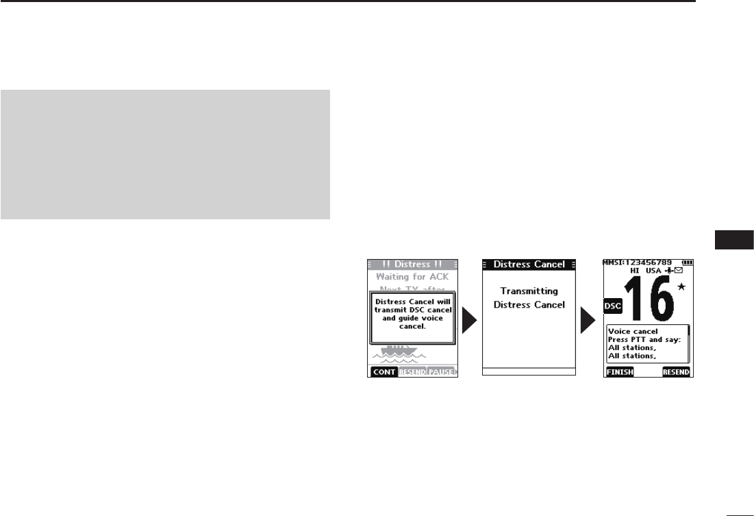
DDistress Cancel call
If you have accidently made a Distress call, or made an
incorrect Distress call, send a Distress Cancel call to
cancel the call as soon as possible while waiting for an
Acknowledgement call, and report the purpose of the
cancellation.
1. While waiting for an Acknowledgement call, push the
software key below [CANCEL].
• The screen below is displayed.
2. Push the software key below [CONT].
• The Distress Cancel call is sent.
• Channel 16 is automatically selected.
3. Hold down [PTT] to report the purpose of the
cancellation.
LYou can display the wording of the cancellation by pushing [▼].
4. After communicating, push the software key below
[FINISH].
• The screen to the right is displayed.
5. Push the software key below [OK] to finish the Distress
Cancel call.
• Returns to the operating screen.
DDistress call software key description
While waiting for an Acknowledgement:
[CANCEL]: Cancels the Distress call and enables you to
send a Cancel call. (See the right column)
[RESEND]: Enables you to resend the Distress call by
holding down [DISTRESS] again.
[PAUSE]: Pauses the countdown to resend the next
Distress call.
[INFO]: Displays the information of the Distress call
that you have sent.
After receiving an Acknowledgement:
[EXIT]: Closes the Distress operation, and returns to
the operating screen.
[HIST]: Displays the “Distress History.”
[INFO]: Displays the information of the received
Distress Acknowledgement.
NOTE (For USA and Export versions):
After sending a Distress call without position data
• While waiting for an Acknowledgement, if valid position data is
received, the transceiver will automatically send a Distress call
again.
• Even after exiting the DSC mode, if valid position data
is received within 20 minutes after receiving a Distress
Acknowledgement, the transceiver will automatically send a
Distress call again.
25
8DSC OPERATION
New2001
■Sending DSC calls (other)
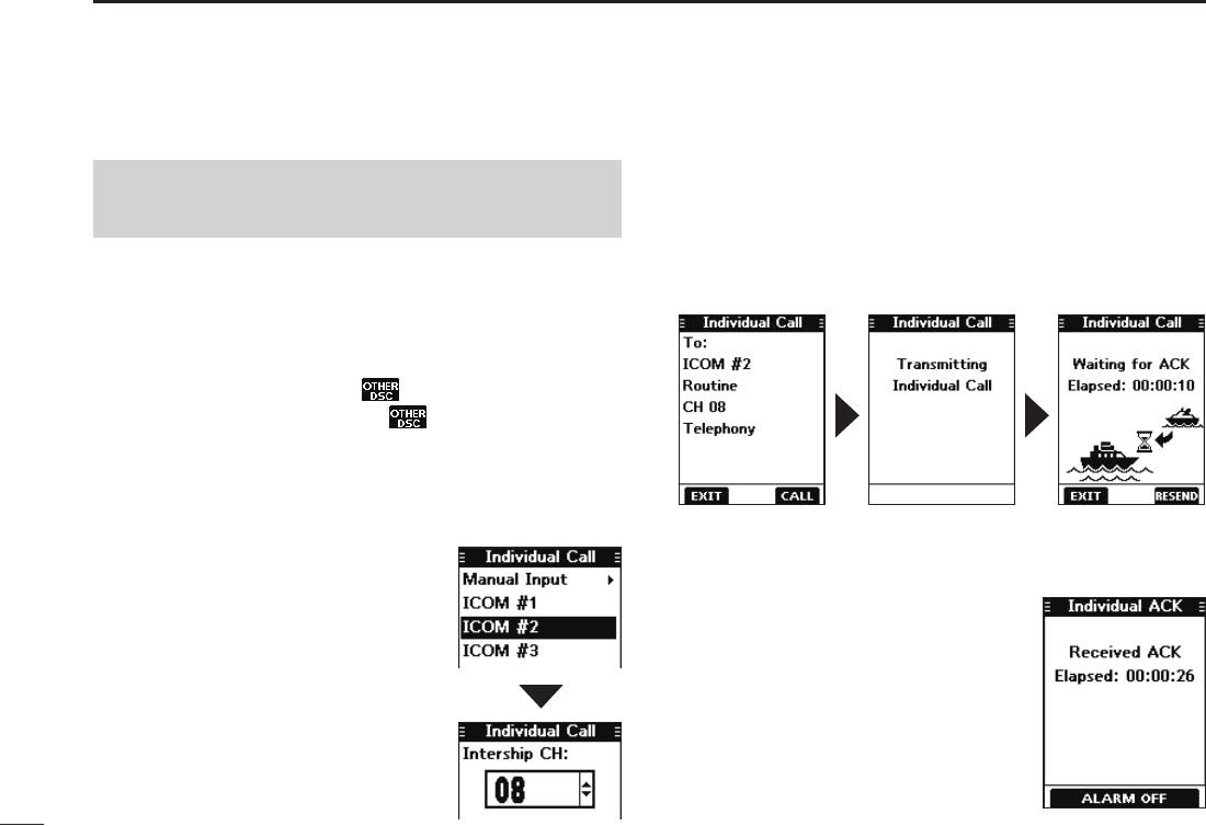
DSending an Individual call
An Individual call enables you to send a DSC signal to only
a specic station. You can communicate after receiving the
Acknowledgement “Able to comply.”
1. Push [◄] or [►] to display .
2. Push the software key below .
• The “Compose Other” screen is displayed.
L You can also display the “Compose Other” screen by
selecting the “Compose Other” item on the Menu screen.
3. Push [▲] or [▼] to select “Individual Call,” and then
push [ENT].
• The “Individual Call” screen is
displayed.
4. Select the station to send an
Individual call to, and the push
[ENT].
L You can also select “Manual Input”
to manually enter the calling station.
5. Select a channel to assign, and
then push [ENT].
L The assigned channels are preset
by default.
6. Push the software key below [CALL] to send the
Individual call.
• “Transmitting Individual Call” is displayed, and then “Waiting
for ACK” is displayed.
L If Channel 70 is busy, the transceiver stands by until the
channel becomes clear.
7. When you receive an Acknowledgement “Able to
comply”:
• An alarm sounds.
• The screen to the right is displayed.
8. Push any software key to turn
OFF the alarm.
• The channel assigned in step 5 is
automatically selected.
L If the called station cannot use
the channel that you assigned, a
different channel is selected by the
station.
9. Hold down [PTT] to communicate.
NOTE: To ensure proper DSC operation, be sure to
correctly adjust the “CH 70 SQL Level” item on the Menu
screen. (p. 44)
26
8
DSC OPERATION
New2001
1
2
3
4
5
6
7
8
9
10
11
12
13
14
15
16
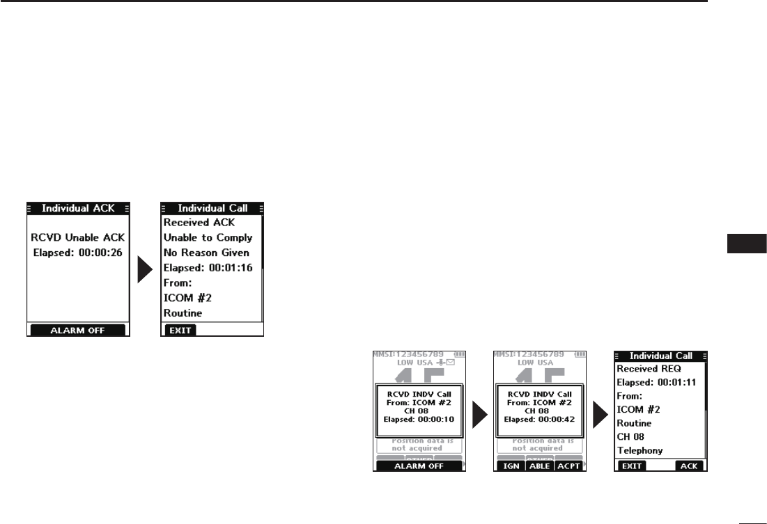
Acknowledgement “Unable to comply”
Push any software key to turn OFF the alarm.
• The Acknowledge information is displayed.
L Push the software key below [EXIT] to return to the operating
screen.
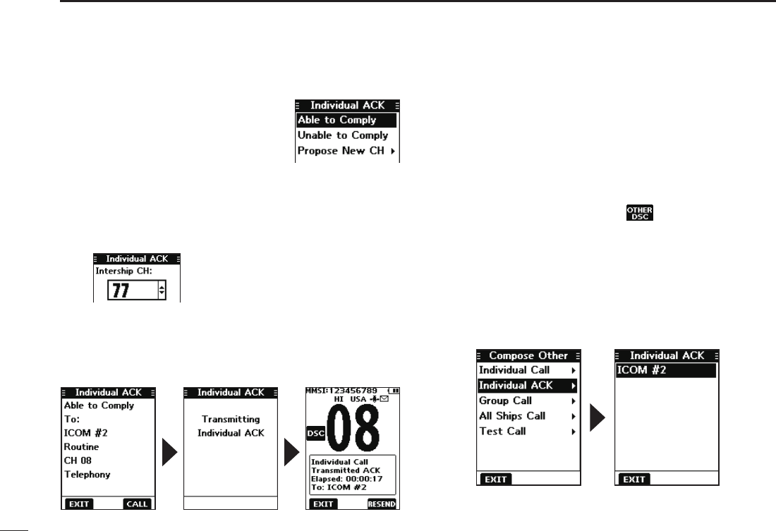
DSending an Individual Acknowledgement
When you have received an Individual call (p. 35), send an
Acknowledgement to the calling station. When you send an
Acknowledgement, select “Able to Comply,” “Propose New
CH,” or “Unable to Comply.”
1. While an Individual call is being received, push any
software key to turn OFF the alarm.
2. Push the software key below [ACPT].
• The received call’s information is displayed.
L If you want to send an Acknowledgement “Able to comply
right away, push the software key below [ABLE].
L If you cannot communicate, and want to return to the
operating screen, push the software key below [IGN].
3. Push the software key below [ACK].
• The Acknowledgement category screen is displayed.
Continued on the next page.
27
8DSC OPERATION
New2001
D Sending an Individual Acknowledgement (Continued)
4. Select “Able to Comply,” “Unable
to Comply,” or “Propose New CH.”
• Able to Comply: Sends an Acknowledgement call
without any changes.
• Unable to Comply: Sends an Acknowledgement call
but cannot communicate.
• Propose New CH: Able to communicate but proposes
another channel.
Specify the channel by pushing [▲]
or [▼]. (Example: Channel 77)
5. Push the software key below [CALL] to send the
Acknowledgement call.
• “Transmitting Individual ACK” is displayed, and then the
assigned channel is automatically selected.
6. Push [PTT] to communicate.
Sending on the “Compose Other” screen
You can also send an Individual Acknowledgement by
selecting “Individual ACK” on the “Compose Other” screen.
This enables you to resend an Acknowledgement,
or send even after sending an “Unable to Comply”
Acknowledgement.
1. Push the software key below .
• The ”Compose Other” screen is displayed.
2. Push [▲] or [▼] to select “Individual ACK,” and then
push [ENT].
• The Individual caller’s station or MMSI is displayed.
L “Individual ACK” is not displayed if no Individual call has
been received.
3. Select the station to send an Acknowledgement call to,
and the push [ENT].
4. Repeat steps 3 to 5 described on the left column.
28
8
DSC OPERATION
New2001
1
2
3
4
5
6
7
8
9
10
11
12
13
14
15
16
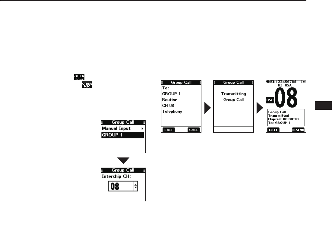
DSending a Group call
A Group call enables you to send a DSC signal to only a
specic group.
L You can send a Group call to a pre-entered group address, or
manually enter the address before sending. (p. 20)
1. Push [◄] or [►] to display .
2. Push the software key below .
• The “Compose Other” screen is displayed.
L You can also display the “Compose Other” screen by
selecting the “Compose Other” item on the Menu screen.
3. Push [▲] or [▼] to select “Group Call,” and then push
[ENT].
• The “Group Call” screen is
displayed.
4. Select the group to send a Group
call to, and the push [ENT].
L You can also select “Manual Input”
to manually enter the target group.
5. Select the channel to assign, and
then push [ENT].
L The assigned channels are preset
by default.
6. Push the software key below [CALL] to send the Group
call.
• “Transmitting Group Call” is displayed, and then the assigned
channel is automatically selected.
L If Channel 70 is busy, the transceiver stands by until the
channel becomes clear.
7.
Hold down [PTT] to communicate.
29
8DSC OPERATION
New2001
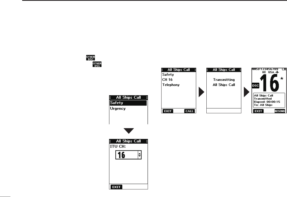
DSending an All Ships call
Except for the USA and Export versions, you can send a call
to all ships that carry DSC transceivers and to those that
use Channel 70 as their listening channel in the range.
1. Push [◄] or [►] to display .
2. Push the software key below .
• The “Compose Other” screen is displayed.
L You can also display the “Compose Other” screen by
selecting the “Compose Other” item on the Menu screen.
3. Push [▲] or [▼] to select “All Ships Call,” and then push
[ENT].
• The “All Ships Call” screen is
displayed.
4. Select the category “Safety” or
“Urgency.”
5. Select the traffic channel to
assign, and then push [ENT].
L The assigned channels are preset
by default.
6. Push the software key below [CALL] to send the All
Ships call.
• “Transmitting All Ships Call” is displayed, and then the
assigned channel is automatically selected.
L If Channel 70 is busy, the transceiver stands by until the
channel becomes clear.
7.
Hold down [PTT] to communicate.
30
8
DSC OPERATION
New2001
1
2
3
4
5
6
7
8
9
10
11
12
13
14
15
16
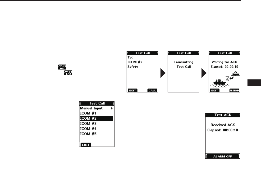
DSending a Test call
You should avoid testing calls on the exclusive DSC distress
channels and safety calling channels. When you cannot
avoid testing on a distress or safety channel, you should
indicate that these are test calls.
Normally the test call would require no further
communications between the two stations involved.
1. Push [◄] or [►] to display .
2. Push the software key below .
• The “Compose Other” screen is displayed.
L You can also display the “Compose Other” screen by
selecting the “Compose Other” item on the Menu screen.
3. Push [▲] or [▼] to select “Test Call,” and then push
[ENT].
• The “Test Call” screen is displayed.
4. Select the station to send the
Test call to.
L You can also select “Manual Input”
to manually enter the calling station.
5. Push the software key below [CALL] to send the Test call.
• “Transmitting Test Call” is displayed.
L If Channel 70 is busy, the transceiver stands by until the
channel becomes clear.
6.
When you receive an Acknowledgement:
• Alarm sounds.
• The screen to the right is displayed.
7. Push any software key to turn
OFF the alarm.
• The Acknowledgement
information is displayed.
8. Push the software key below
[EXIT].
• “Terminate the Procedure Are
you sure?” is displayed.
9. Push the software key below
[OK] to return to the operating
screen.
31
8DSC OPERATION
New2001
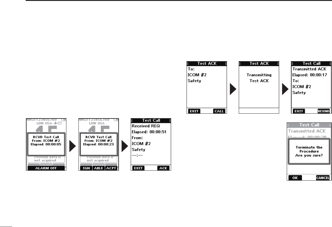
DSending a Test Acknowledgement
By default, when you receive a Test call, the Auto ACK
function automatically sends an Acknowledgement to the
calling station (p. 42). If the function is set to “Manual,” do
the following steps to send an Acknowledgement.
1. After a Test call is being received, push any software
key to turn OFF the alarm.
2. Push the software key below [ACPT].
• The received call’s information is displayed.
L If you want to send an “Able to comply” Acknowledgement
right away, push the software key below [ABLE].
3. Push the software key below [ACK].
• The “Test ACK” conrmation screen is displayed.
4. Push the software key below [CALL] to send the
Acknowledgement.
• “Transmitting Test ACK” is displayed.
5. Push the software key below
[EXIT].
• A confirmation screen is displayed.
6. Push the software key below [OK]
to return to the operating screen.
32
8
DSC OPERATION
New2001
1
2
3
4
5
6
7
8
9
10
11
12
13
14
15
16
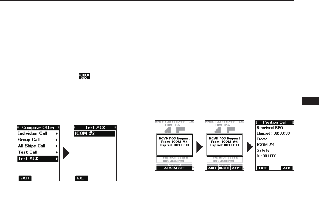
Sending on the “Compose Other” screen
You can also send a Test Acknowledgement by selecting
“Test ACK” on the “Compose Other” screen.
This enables you to resend an Acknowledgement, or send
even after ignoring the call when you rst received it.
1. Push the software key below .
• The ”Compose Other” screen is displayed.
2. Push [▲] or [▼] to select “Test ACK,” and then push
[ENT].
• The Test caller’s station or MMSI is displayed.
L “Test ACK” is not displayed if no Test call has been received.
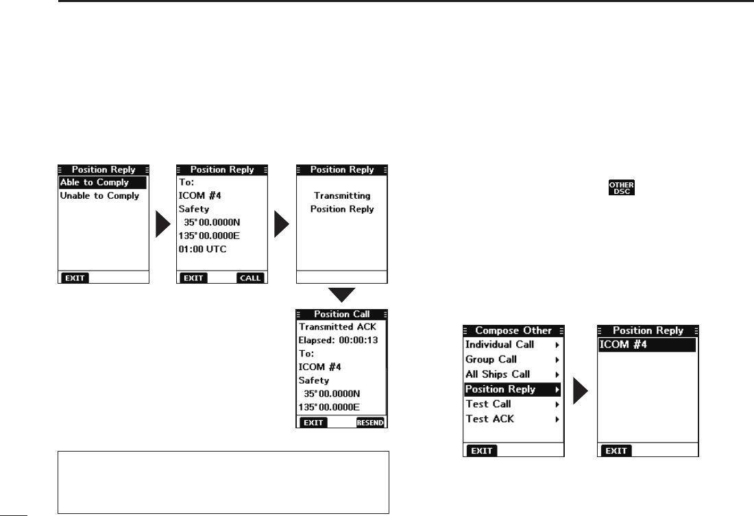
DSending a Position Reply call
Send a Position Reply call when a Position Request call
is received. If the Auto ACK function is set to “Auto,” the
Acknowledgement is automatically sent to the calling
station. (p. 42)
1. While a Position Request call is being received, push
any software key to turn OFF the alarm.
2. Push the software key below [ACPT].
• The received call’s information is displayed.
L If you want to send an “Able to Comply” Acknowledgement
right away, push the software key below [ABLE].
L If you cannot send a reply call, push the software key below
[UNABL].
3. Push the software key below [ACK].
Continued on the next page.
33
8DSC OPERATION
New2001
4. Select the reply “Able to Comply.”
LSelect “Unable to Comply” if you cannot send a reply call.
5. Push the software key below [CALL] to send the reply.
• “Transmitting Position Reply” is displayed.
• After sending, the replied information is displayed.
6. Push the software key below [EXIT]
to return to the operating screen, or
below [RESEND] to resend.
• A confirmation screen is displayed.
7. Push the software key below [OK]
to return to the operating screen.
D Sending a Position Reply call (Continued)
Sending on the “Compose Other” screen
You can also send a Position Reply call by selecting
“Position Reply” on the “Compose Other” screen.
This enables you to reply even after ignoring the call when
you rst received it.
1. Push the software key below .
• The ”Compose Other” screen is displayed.
2. Push [▲] or [▼] to select “Position Reply,” and then
push [ENT].
• The caller’s station or MMSI is displayed.
L “Position Reply” is not displayed if no Position Request call
has been received.
3. Select the station to send a Position Reply call to, and
the push [ENT].
4. Repeat steps 4 to 7 described in the left column.
TIP: If no valid position is received while selecting [ACPT]
in step 2, and selecting “Able to Comply,” the position and
time entry screen is displayed.
LSee “Entering the position and time” on page 22 for details.
34
8
DSC OPERATION
New2001
1
2
3
4
5
6
7
8
9
10
11
12
13
14
15
16
■
Receiving DSC calls (Distress)
The transceiver receives Distress calls, Distress
Acknowledgement calls, and Distress Cancel calls.
L When you receive a call, an emergency alarm sounds.
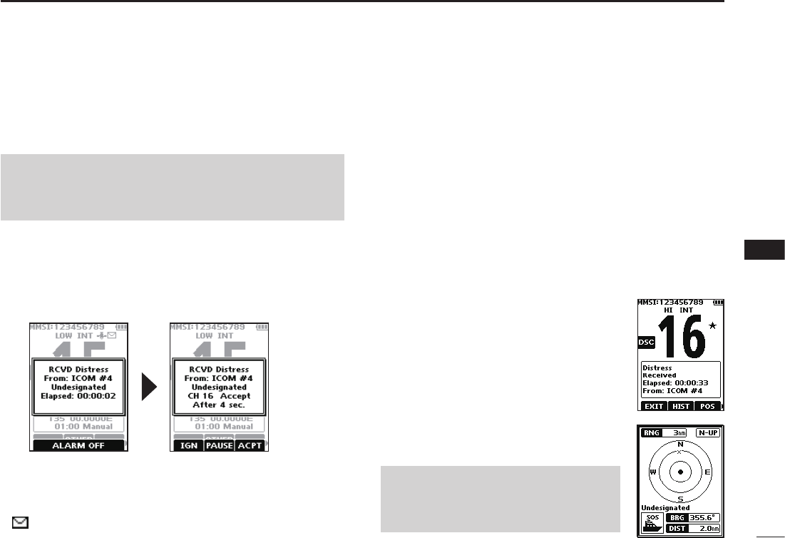
When a Distress call is received:
• The emergency alarm sounds until you turn it OFF.
• “RCVD Distress” is displayed.
1. Push any software key to turn OFF the alarm.
2. Push the software key below the intended operation.
[IGN]
• Returns to the operating screen.
• The call is saved in the DSC Log.
• “ ” blinks continuously until you display the call message.
[PAUSE]
L [PAUSE] is not displayed if the “CH Auto Switch” item is set to
“Manual.” (p. 42)
• Pauses the countdown until the assigned channel is
automatically selected.
• Select [RESUME] to resume the countdown.
• The call is saved in the DSC Log.
NOTE: The screens that are displayed when a Distress
call or an Acknowledgement call is received slightly differ
from one another. The following steps are described using
an example of receiving a Distress call. [ACPT]
• Accepts the call.
• Channel 16 is automatically selected.
• Monitor Channel 16 as a coast station may require
assistance.
• After Channel 16 is selected, you can
select your next operation by pushing the
software key below the following options.
[EXIT]: Returns to the operating screen.
[HIST]:
Displays the “Distress History” screen.
[POS]:
Displays the position of the calling
station on a map*.
L
The map is not updated,even as your
vessel moves.
[INFO]: Displays the information of the
received Distress call.
*Note on the map:
See “Navigation screen description” on
page 49 for details on “RNG,” “N-UP,”
“BRG,” and “DIST.ˮ
35
8DSC OPERATION
New2001
■Receiving DSC calls (other)
The transceiver receives the following types of DSC calls.
•Individual call (p. 35)
•Individual Acknowledgement call (p. 25)
•Group call (p. 36)
•All Ships call (p. 37)
•Position Request call (p. 38)
•Test call (p. 39)
•Test Acknowledgement call (p. 40)
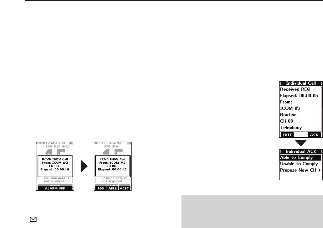
DReceiving an Individual call
When an Individual call is received:
• The alarm sounds.
• “RCVD INDV Call” is displayed.
1. Push any software key to turn OFF the alarm.
2. Push the software key below the next operation.
[IGN]
• Ignores the call and returns to the operating screen.
• The call is saved in the DSC Log.
• “ ” blinks continuously until you display the call message.
[ACPT]
• Accepts the call.
• The assigned channel is automatically
selected.
• The call is saved in the DSC Log.
• The received call’s information is
displayed.
• Push the software key below [ACK] to
select the Acknowledgement option.
Able to Comply:
Sends an Acknowledgement call without
any changes.
Unable to Comply:
Sends an Acknowledgement but you
cannot communicate.
Propose New CH:
Sends an Acknowledgement call but on
another channel. Assign the channel by
pushing [▲] or [▼].
[ABLE]
• Sends an Individual Acknowledgement call right away.
• The assigned channel is automatically selected.
• After sending, [RESEND] to resend.
• The call is saved in the DSC Log.
NOTE: If the Auto ACK function is set to “Auto (Unable)”
the Acknowledgement “Unable to Comply” is automatically
sent to the calling station when the call is received. (p. 42)
L For the USA and Export versions, this function is set to
“Auto (Unable)” by default.
36
8
DSC OPERATION
New2001
1
2
3
4
5
6
7
8
9
10
11
12
13
14
15
16
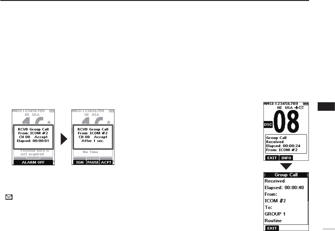
DReceiving a Group call
When a Group call is received:
• The alarm sounds for 2 minutes.
• “RCVD Group Call” is displayed.
1. Push any software key to turn OFF the alarm.
L The channel that is assigned by the caller is automatically
selected after 10 seconds by default.
2. Push the software key below your next operation.
[IGN]
• Ignores the call and returns to the operating screen.
• The call is saved in the DSC Log.
• “ ” blinks continuously until you display the call message.
[ACPT]
• Accepts the call.
• The assigned channel is selected.
• The call is saved in the DSC Log.
[EXIT]
Closes the Group call, and then
returns to the operating screen.
[INFO]
The received call’s information is
displayed.
[PAUSE]
L [PAUSE] is not displayed if the “CH Auto Switch” item is set to
“Manual.” (p. 42)
• Pauses the countdown until the assigned channel is
automatically selected.
• Select [RESUME] to resume the countdown.
• The call is saved in the DSC Log.
37
8DSC OPERATION
New2001
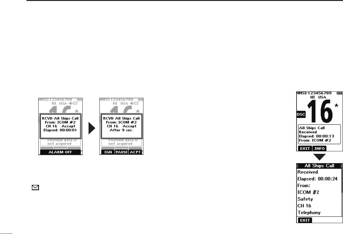
DReceiving an All Ships call
When an All Ships call is received:
• The alarm sounds.
• “RCVD All Ships Call” is displayed.
1. Push any software key to turn OFF the alarm.
L The trafc channel that is assigned by the caller is
automatically selected after 10 seconds by default.
2. Push the software key below your next operation.
[IGN]
• Ignores the call and returns to the operating screen.
• The call is saved in the DSC Log.
• “ ” blinks continuously until you display the call message.
[ACPT]
• Accepts the call.
• The assigned channel is selected.
• The call is saved in the DSC Log.
[EXIT]
Closes the All Ships call, and then
returns to the operating screen.
[INFO]
The received call’s information is
displayed.
[PAUSE]
L [PAUSE] is not displayed if the “CH Auto Switch” item is set to
“Manual.” (p. 42)
• Pauses the countdown until the assigned channel is
automatically selected.
• Select [RESUME] to resume the countdown.
• The call is saved in the DSC Log.
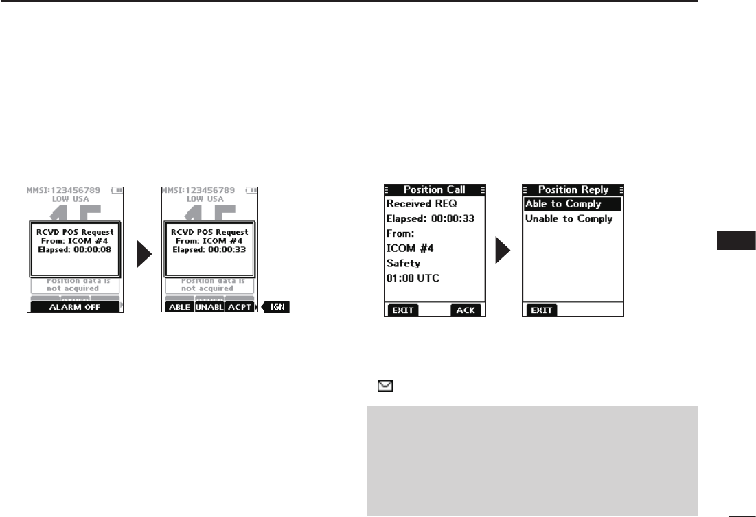
38
8
DSC OPERATION
New2001
1
2
3
4
5
6
7
8
9
10
11
12
13
14
15
16
DReceiving a Position Request call
When a Position Request call is received:
• The alarm sounds for 2 minutes.
• “RCVD POS Request” is displayed.
1. Push any software key to turn OFF the alarm.
2. Push the software key below the intended operation.
[ABLE]
• Sends the Acknowledgement “Able to Comply.”
• The call is saved in the DSC Log.
[UNABL]
• Sends the Acknowledgement “Unable to Comply.”
• Displays the Acknowledgement information, and then
returns to the operating screen by pushing the software
key below [EXIT].
• The call is saved in the DSC Log.
[ACPT]
• Accepts the call.
• Displays the received call’s information.
• The call is saved in the DSC Log.
• Push the software key below [ACK] to send the Position
Reply call. (p. 33)
[IGN]
• Ignores the call and returns to the operating screen.
• The call is saved in the DSC Log.
• “ ” blinks continuously until you display the call message.
NOTE:
• If the Auto ACK function is set to “Auto,” the Position
Reply is automatically sent to the calling station. (p. 42)
• However, even if the Auto ACK function is set to
“Manual,” after receiving a Distress Acknowledgement, or
while in the Distress Cancel call procedure, the Position
Reply is automatically sent to the calling station.
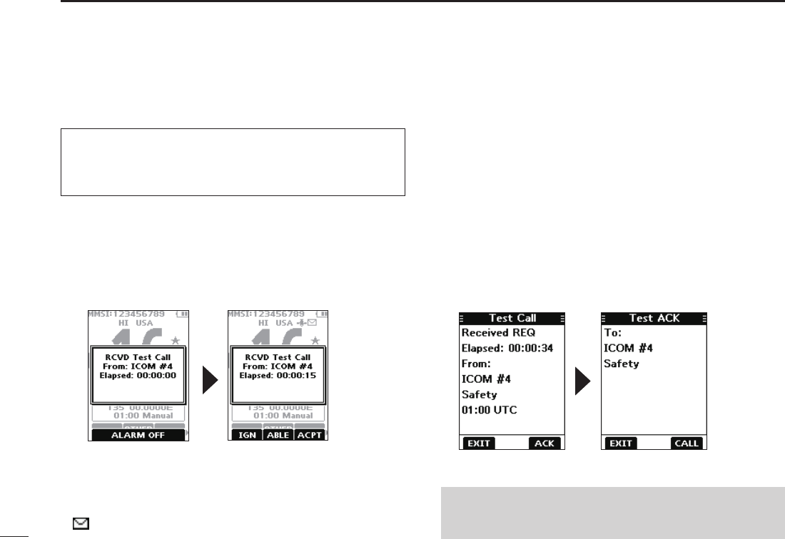
39
8DSC OPERATION
New2001
DReceiving a Test call
1. Push any software key to turn OFF the alarm.
2. Push the software key below your next operation.
[IGN]
• Ignores the call and returns to the operating screen.
• The call is saved in the DSC Log.
• “ ” blinks continuously until you display the call message.
[ABLE]
• Sends the Acknowledgement “Able to Comply.”
• The call is saved in the DSC Log.
[ACPT]
• Accepts the call.
• Displays the received call’s information.
• The call is saved in the DSC Log.
• Push the software key below [ACK] to send a Test
Acknowledgement call. (p. 32)
• Push the software key below [RESEND] to resend.
NOTE: If the Auto ACK function is set to “Auto,” the Test
Acknowledgement call is automatically sent to the calling
station when the call is received. (p. 42)
When a Test call is received:
• The alarm sounds for 2 minutes.
• “RCVD Test Call” is displayed.
TIP: By default, the Auto ACK function automatically
sends an Acknowledgement to the calling station (p. 42).
If the function is set to “Manual,” the following screens are
displayed.
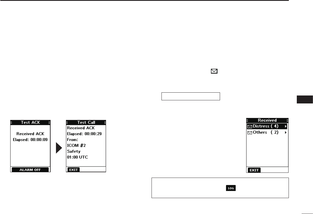
40
8
DSC OPERATION
New2001
1
2
3
4
5
6
7
8
9
10
11
12
13
14
15
16
DReceiving a Test Acknowledgement call
After sending a Test call, the called station will send you a
Test Acknowledgement call.
Push any software key to turn OFF the alarm.
• The received call’s information is displayed.
• The call is saved in the DSC Log.
L Push the software key below [EXIT] to return to the operating
screen.
When a Test Acknowledgement call is received:
• The alarm sounds for 2 minutes.
• “Received ACK” is displayed.
■DSC Log
DReceived DSC Log
The transceiver saves up to 50 received Distress call
messages and 50 received “Others” call messages in your
DSC Log.
On the operating screen, “ ” is displayed when there is an
unread call message.
[MENU] ► “DSC Log”
1. Display the “DSC Log” screen.
2. Push [▲] or [▼] to select “Received,” and then push
[ENT].
• The “Received” screen is displayed.
3. Push [▲] or [▼] to select
“Distress” or “Others,” and then
push [ENT].
L “Distress” displays the received
Distress call log, and “Others”
displays the received DSC call log.
TIP: You can also display the “Received” screen by
pushing the software key below on the operating
screen.
Continued on the next page.
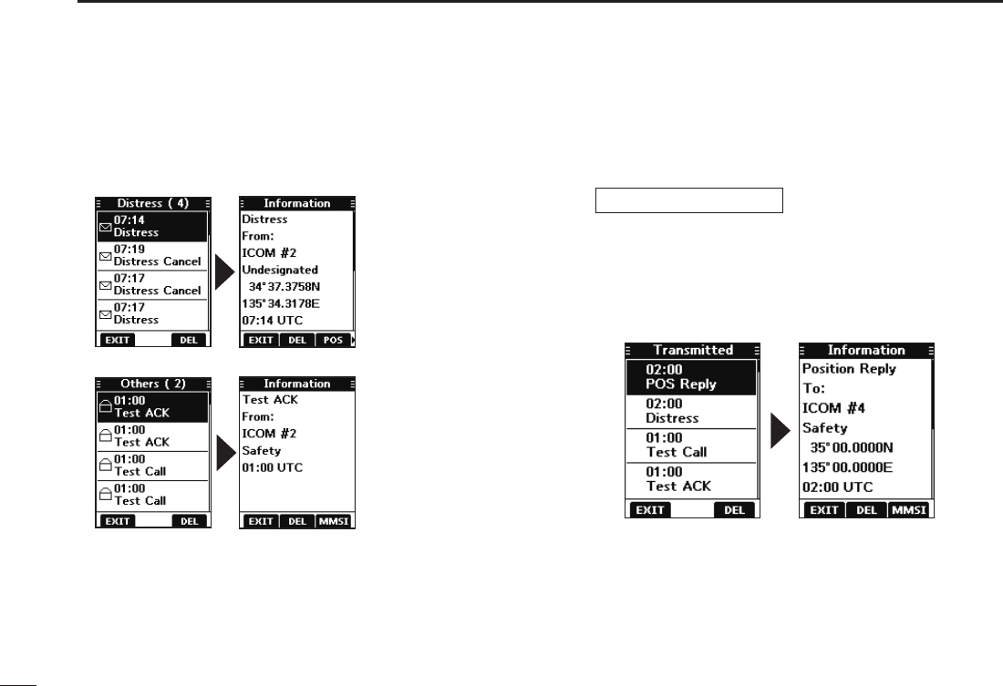
41
8DSC OPERATION
New2001
DReceived DSC log (Conitnued)
4. Push [▲] or [▼] to scroll through the log.
5. Push [ENT] to display the received call’s information.
Received Distress log
Received DSC log
DSent DSC Log
The transceiver saves up to 50 DSC sent calls in your DSC
Log.
[MENU] ► “DSC Log”
1. Display the “DSC Log” screen.
2. Push [▲] or [▼] to select “Transmitted,” and then push
[ENT].
• The “Transmitted” screen is displayed.
3. Push [▲] or [▼] to scroll through the log.
4. Push [ENT] to display the sent call’s information.
[EXIT]: Returns to the operating screen.
[DEL]: Deletes the selected call log.
LConrmation screen is displayed before deleting.
[POS]: Displays the position of the called station.
LThis option is not displayed if no position data is received.
[MMSI]: Saves the MMSI as an Individual ID.
[WP]: Enters the received position as a Waypoint. (p. 47)

42
8
DSC OPERATION
New2001
1
2
3
4
5
6
7
8
9
10
11
12
13
14
15
16
■DSC Settings
On the “DSC Settings” screen, you can make settings on
the DSC call related items.
Position Input
See “Entering the position and time” on page 21 for details.
Individual ID
See “Entering an Individual ID” on page 19 for details.
Group ID
See “Entering a Group ID” on page 20 for details.
Auto ACK
The Auto ACK function automatically sends an
Acknowledgement call when the following calls are received.
• Individual call (Default: Differs depending on the version)
• Position Request call (Default: Manual)
• Test call (Default: Auto)
Manual: Manually send an Acknowledgement call.
Auto: Automatically send an Acknowledgement call.
CH Auto Switch (Default: Accept)
Select whether or not to automatically switch to channel
16 or the specied channel, or select whether to switch or
ignore the call.
Accept: After receiving a DSC call, the transceiver remains
on the operating channel for 10 seconds. After
that, the transceiver automatically switches to the
channel that is specied on the DSC call.
Ignore: After receiving a DSC call, if you do not push the
software key below [ACPT] in 10 seconds, the
transceiver ignores the call, and then remains on
the current operating channel.
Manual: After receiving a DSC call, you can select whether
or not to accept the received DSC call.
DSC Switch (Default: On)
Select whether or not to receive and send DSC calls.
L You can send Distress calls despite of this setting.
On: Receives and sends DSC calls.
Off (TEMP): Does not receive or send DSC calls until you
turn OFF the transceiver.
Off: Does not receive or send DSC calls.
TIP: When “Auto” is set to the Individual call, the
Acknowledgement “Unable to Comply” is automatically sent when
the call is received.

43
8DSC OPERATION
New2001
Unread Return (Default: On)
This function puts the received DSC call on hold while
receiving another call.
On: While receiving another call, the received DSC call is
put on hold until the currently receiving call is hung up.
Off: While receiving another call, the received DSC call is
saved in the DSC Log.
MOB Auto Set
• MOB Key (Default: On (30 sec))
For 30 seconds after entering the MOB waypoint, this function
automatically sets the Nature of Distress as “Man Overboard.”
On (30 sec): The Nature of Distress is automatically set
to “Man Overboard” for 30 seconds after
entering the MOB waypoint.
Off: The function is OFF.
•Water Detection (Default: On (30 sec))
For 30 seconds after the transceiver has detected water,
this function automatically sets the Nature of Distress as
“Man Overboard.”
On (30 sec): The Nature of Distress is automatically set
to “Man Overboard” for 30 seconds after the
transceiver has detected water.
Off: The function is OFF.
■DSC Settings (Continued)
Alarm Status
Set the alarm ON or OFF for each DSC related item.
•Safety (Default: On)
An alarm sounds when a Safety DSC call is received.
• Routine (Default: On)
An alarm sounds when a Routine DSC call is received.
• Warning (Default: On)
An alarm sounds when:
- no MMSI code is entered.
- the position data has not been received for 2 minutes
after turning ON the transceiver.
- the received position data has not been updated for 10
minutes.
- the received position data or manually entered position
data has not been updated for 4 hours.
• Self-Terminate (Default: On)
An alarm sounds when duplicate Distress calls are
received.
• Discrete (Default: On)
An alarm sounds when a lower priority call is received
while receiving a high priority call.
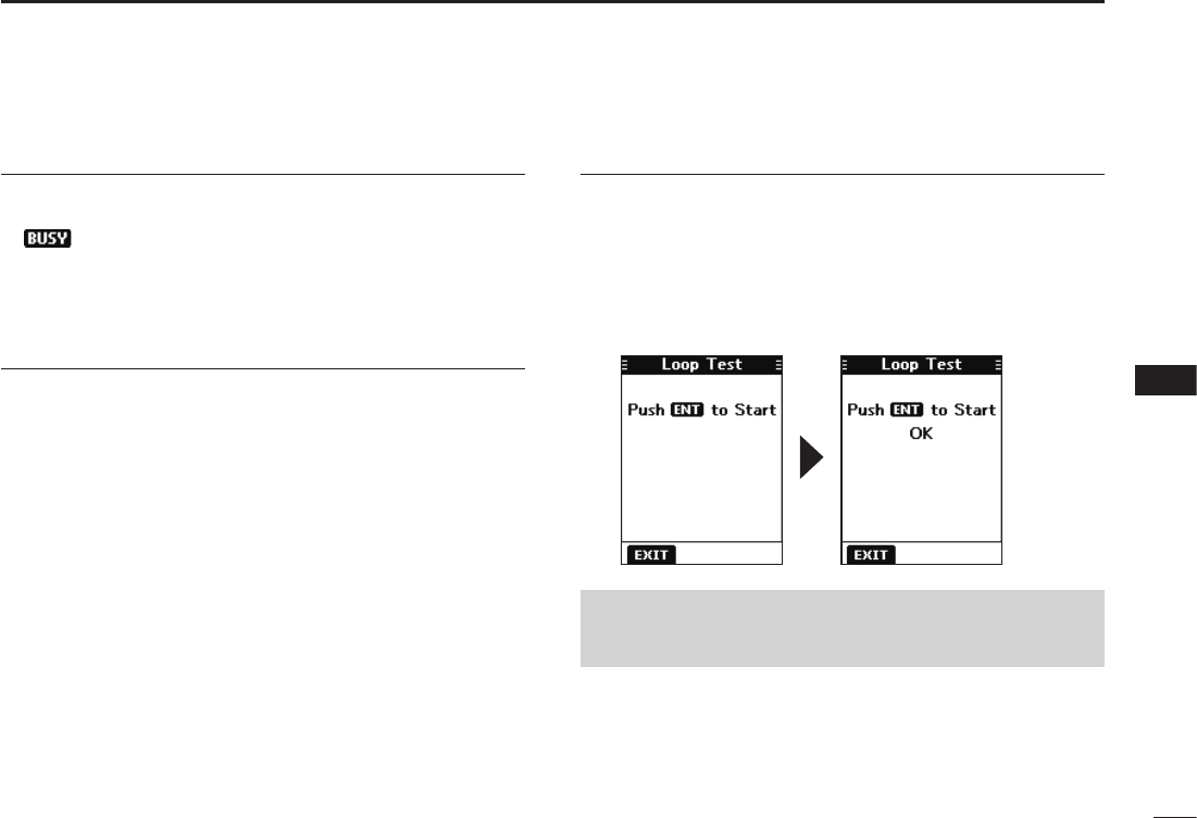
44
8
DSC OPERATION
New2001
1
2
3
4
5
6
7
8
9
10
11
12
13
14
15
16
CH 70 SQL Level (Default: 5)
Adjust the Squelch level for Channel 70 to between 1 and
10, or Open.
L“” is displayed when adjusted to Open.
A higher level blocks weak signals, which enables you to
send a DSC call.
DST at PW Off (Default: Valid)
This function enables you to send Distress calls even while
the transceiver is OFF.
Valid: You can send Distress calls by holding down
[DISTRESS], even while the transceiver is OFF.
Invalid: You cannot send Distress calls while the
transceiver is OFF.
Loop Test
This function sends DSC signals to the receiving AF circuit
to compare the sending and receiving signals at the AF
level.
Push [ENT] to start the Loop Test.
L When the sending and receiving DSC signals match, “OK” is
displayed.
NOTE: If “NG” is displayed, either or both the sending and
receiving DSC circuits have a problem. In that case, you
will have to send the transceiver to your dealer for repair.
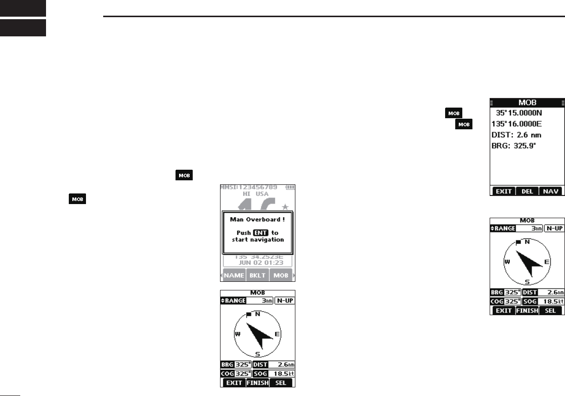
45
9OTHER FUNCTIONS
■MOB (Man OverBoard)
You can enter a Man OverBoard (MOB) waypoint into the
transceiver with its GPS position data, as soon as a person
has fallen into the water and needs to be rescued. This
enables you to reach the MOB position even in the dark, or
when you have lost visual contact.
DEntering an MOB waypoint
1. Push[◄]or[►]todisplay .
DMOB screen
1. Push[◄]or[►]todisplay .
2. Push the software key below .
• The “MOB” screen is displayed.
L You can also display the “MOB”
screen by selecting the “MOB” item
on the Menu screen.
L “No Entry” is displayed if no MOB
waypoint is entered.
3. Push the software key below
[NAV]tostartthenavigation,
[DEL]todeletetheentry,and
[EXIT]toclosethe“MOB”screen.
Navigating to the MOB waypoint:
The transceiver can navigate you to
the MOB waypoint.
Pushthesoftwarekeybelow[NAV].
L See page 48 for navigation details.
2. Hold down the software key below
for 1 second to enter the
MOB waypoint.
• After entering, “Man Overboard!” is
displayed.
L You cannot enter the MOB waypoint
if no GPS data is received.
L You can only enter 1 MOB waypoint,
and the previously entered point is
overwritten when a new waypoint is
entered.
3. Push[ENT]tostartthenavigating
to the entered point.
L See page 48 for navigation details.
LPushthesoftwarekeybelow[EXIT]
to stop the navigation and return to
the operating screen.
Deleting the MOB waypoint:
1. Pushthesoftwarekeybelow[DEL]todeletetheMOB
waypoint.
• “Are you sure?” is displayed.
2. Pushthesoftwarekeybelow[OK]todelete.
L You can cancel the deletion by pushing the software key
below[CANCEL].
• “No Entry” is displayed.
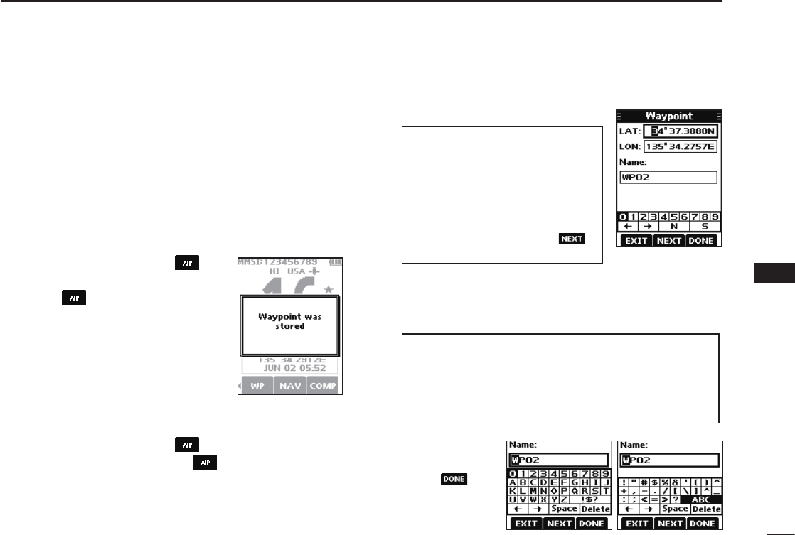
46
9
OTHER FUNCTIONS
1
2
3
4
5
6
7
8
9
10
11
12
13
14
15
16
■Waypoint
Waypoints are GPS position data points of places you want
to go to, the position of your own vessel, or of a vessel you
received a DSC call from. You can enter up to 50 Waypoints
with names of up to 10 characters. You can enter your
current position information, or add one as a destination or
landmarks you often go to, as information for easy access.
DEntering a Waypoint
Entering your current position as a Waypoint:
1. Push[◄]or[►]todisplay .
2. Hold down the software key
below for 1 second.
• “Waypoint was stored” is displayed.
• The current position is entered as a
Waypoint.
L You cannot register a Waypoint if
no GPS data is received.
3. Push [CLRé]toreturntothe
operating screen.
Manually entering a Waypoint:
1. Push[◄]or[►]todisplay .
2. Push the software key below .
• The “Waypoint” screen is displayed.
3. Push[◄]or[►]todisplay[ADD].
4. Pushthesoftwarekeybelow[ADD].
• Enters the Waypoint entry mode.
• The current position is displayed in the entry boxes.
Waypoint entry mode
TIP:
• Select a number or the compass
directionusing[▲]/[▼]/[◄]/[►].
• Push[ENT]toentertheselected
number.
• Select“←”or“→,”tomovethe
cursor.
• Push the software key below to
select latitude, longitude, and name.
TIP:
• Select[!$?]tousecharacters,andselect[ABC]touse
numbers and letters.
• Selectcharactersorspaceusing[▲]/[▼]/[◄]/[►].
• Push[ENT]toentertheselectedcharacter.
• Select“←”or“→,”tomovethecursor.
5. Edit the latitude and longitude.
Entering a Waypoint name:
1. After editing the latitude and longitude, push the
softwarekeybelow[NEXT]toselect“Name.”
2. Push the
software key
below to
save the edited
name.
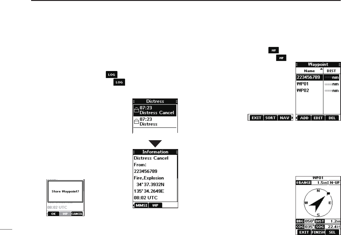
47
9OTHER FUNCTIONS
■Waypoint (Continued)
DEntering a received position
After receiving a Distress call that includes position data,
you can enter the position as a Waypoint. This enables you
to reach the caller’s position.
1. Push[◄]or[►]todisplay .
2. Push the software key below .
• The “Received” screen is displayed.
3. Push[▲]or[▼]toselect“Distress.”
4. Select the received call and then
push[ENT].
• The received DSC call’s GPS
position data is displayed on the
“Information” screen.
5. Push[◄]or[►]todisplay[WP].
• “Store Waypoint?” is displayed.
6. Push the software key below
[OK]toenter.
DWaypoint screen
1. Push[◄]or[►]todisplay .
2. Push the software key below .
• The “Waypoint” screen is displayed.
L You can also display the “Waypoint”
screen by selecting the “Waypoint”
item on the Menu screen.
3. Push[◄]or[►]toscrollthrough
[EXIT],[SORT],[NAV],[ADD],
[EDIT],and[DEL].
Push[◄]or[►].
Sorting the Waypoint list:
You can sort the Waypoint list by the Waypoint or MMSI
name, or by the distance from your vessel.
Pushthesoftwarekeybelow[SORT]tosortthelist.
• “▲”or“▼”isdisplayednextto“Name”or“DIST.”
LEach push changes the sorting order.
Navigating to a Waypoint:
The transceiver can navigate you to
an entered Waypoint.
Pushthesoftwarekeybelow[NAV].
L See page 48 for navigation details.
• The position is entered on the “Waypoint” screen.
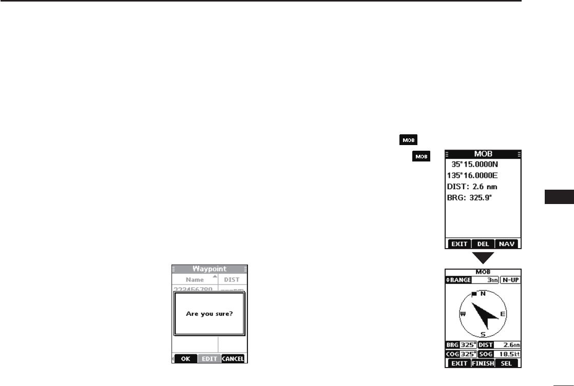
48
9
OTHER FUNCTIONS
1
2
3
4
5
6
7
8
9
10
11
12
13
14
15
16
Adding a Waypoint:
Pushthesoftwarekeybelow[ADD]toaddaWaypoint.
L Add the Waypoint in the same manner that is described in
“Manually entering a Waypoint” on page 46.
Editing a Waypoint:
While selecting the Waypoint that you want to edit, push the
softwarekeybelow[EDIT]toedittheWaypoint.
L Edit the Waypoint in the same manner “Manually entering a
Waypoint” on page 46 for editing a Waypoint.
Deleting a Waypoint:
1. Select the Waypoint that you want to delete, and then
pushthesoftwarekeybelow[DEL]todeleteit.
• “Are you sure?” is displayed.
2. Push the software key below
[OK]todelete.
LSelect[CANCEL]tocancelthe
deletion.
■Navigation
The Navigation function navigates from your current position
to an entered regular Waypoint or MOB waypoint.
Start navigating to the MOB waypoint:
L The MOB waypoint must be entered before navigating.
1. Push[◄]or[►]todisplay .
2. Push the software key below .
• The “MOB” screen is displayed.
3. Push the software key below
[NAV]tostartnavigatingtothe
MOB waypoint.
• The navigation starts.
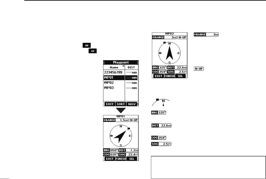
49
9OTHER FUNCTIONS
■Navigation (Continued)
Start navigating to a Waypoint:
L A Waypoint must be entered before navigating.
1. Push[◄]or[►]todisplay .
2. Push the software key below .
• The “Waypoint” screen is displayed.
3. Push[▲]or[▼]toselecta
Waypoint.
4. After selecting, push the
softwarekeybelow[NAV]tostart
navigating to the Waypoint.
DNavigation screen description
Range displays the radius of a
compass circle.
Push[▲]or[▼]tochangetherange
between 0.125, 0.25, 0.5, 0.75, 1.5,
3, 6, and 12 nm.
Displays the display’s direction type.
Pushthesoftwarekeybelow[SEL]to
select “N-UP,” “AC-UP,” or “WP-UP.”
LSee page 57 for details.
Thisagiconindicatesthedirectiontoreachthe
target Waypoint or MOB waypoint.
Displays the bearing of the target Waypoint or
MOB waypoint from your vessel.
Displays the Course Over Ground.
Displays the distance to the Waypoint or MOB
waypoint.
Displays the Speed Over Ground.
TIP: Once the navigation starts, it continues even if you
close the Navigation screen by pushing the software key
below[EXIT].Toproperlynishthenavigation,pushthe
softwarekeybelow[FINISH].
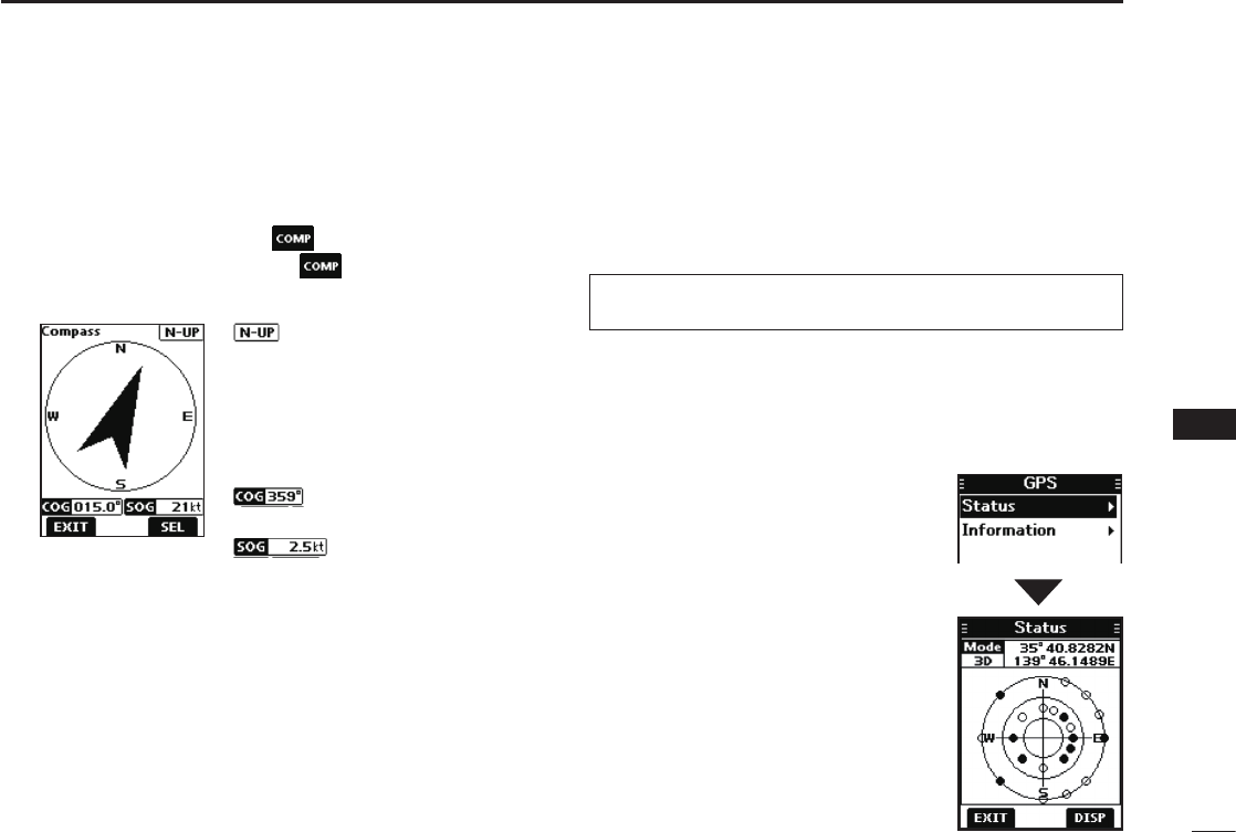
50
9
OTHER FUNCTIONS
1
2
3
4
5
6
7
8
9
10
11
12
13
14
15
16
■Compass
The Compass shows your vessel’s Course Over Ground
(COG) and Speed Over Ground (SOG).
1. Push[◄]or[►]todisplay .
2. Push the software key below .
• The “Compass” screen is displayed.
Displays the display’s direction
type.
Push the software key below
[SEL]toselect“N-UP”or“AC-UP.”
LSee page 57 for details.
Displays the Course Over Ground.
Displays the Speed Over Ground.
3. Pushthesoftwarekeybelow[EXIT]toclosethe
“Compass” screen, and return to the operating screen.
■GPS/GNSS
The GPS or GNSS “Status” screen displays the quantity,
signal power, and position of the GPS satellites in the sky
view. The screen also displays the direction, elevation angle,
satellite numbers, and their received signal strength.
2. Push[▲]or[▼]toselect“GPS,”
andthenpush[ENT].
• The “GPS” screen is displayed.
L “GNSS” may be displayed, instead
of “GPS,” depending on the
transceiver version.
3. Push[▲]or[▼]toselect“Status”
andthenpush[ENT].
• The “Status” screen is displayed.
DGPS/GNSS Status screen
Displaying the Status screen:
1. Push[MENU].
• The Menu screen is displayed.
TIP: Use the transceiver outdoors so the receiver has a
clear view to receive GPS signals from the satellites.
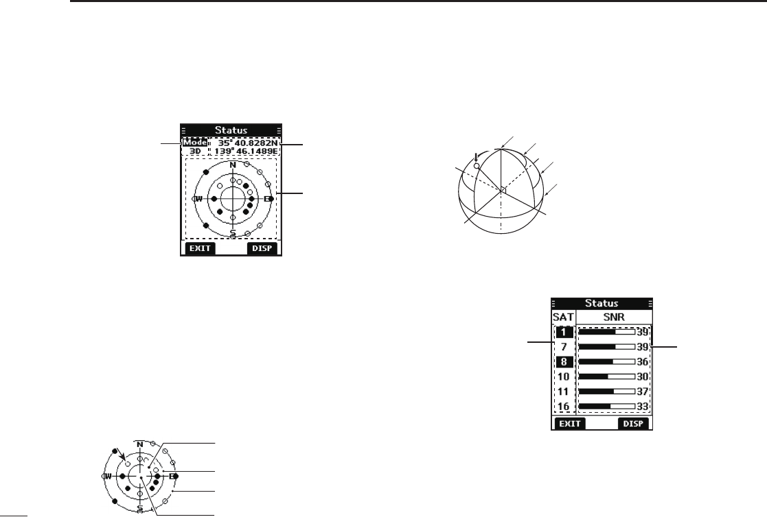
51
9OTHER FUNCTIONS
N
W
E
S
Satellite A
Elevation angle 90 degree line (Zenith)
Elevation angle 60 degree line
Elevation angle 30 degree line
Elevation angle 0 degree line
Your position
Sky view
GPS mode*
* “2D” is displayed while tracking 3 or less satellites. “3D” is
displayed while tracking more than 4 or more satellites.
DGPS/GNSSStatusscreen(Continued)
Sky view description:
zPushthesoftwarekeybelow[DISP]todisplaytheGPS/
GNSS status in the sky view or on the satellite signal
strength status screen.
zPushthesoftwarekeybelow[EXIT]toreturntothe
operating screen.
Satellite signal strength status description:
Satellite signal
strength level
Satellite number
LThe untracking satellite numbers blink.
LPush[▲]or[▼]toscrollthroughallthesatellitenumbers.
•Image of the satellite
Satellite A
Elevation angle 0 degree line
Elevation angle 60 degree line
Elevation angle 30 degree line
Elevation angle 90 degree line (Zenith)
●: Tracking satellite
○: Untracking satellite
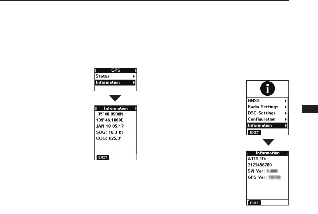
52
9
OTHER FUNCTIONS
1
2
3
4
5
6
7
8
9
10
11
12
13
14
15
16
DGPS/GNSS Information screen
Information screen description:
1. Push[MENU].
• The Menu screen is displayed.
2. Push[▲]or[▼]toselect“GPS,”
andthenpush[ENT].
• The “GPS” screen is displayed.
L “GNSS” may be displayed, instead
of “GPS,” depending on the
transceiver version.
3. Push[▲]or[▼]toselect
“Information” and then push
[ENT].
• The “Information” screen is displayed.
L The “Information” screen displays
your position, date, time, Speed
Over Ground (SOG), and Course
Over Ground (COG).
■Information screen
You can check your transceiver’s software version, GPS
module version, and ATIS ID* on the “Information” screen.
* Only for the Dutch and German versions.
1. Push[MENU].
• The Menu screen is displayed.
2. Push[▲]or[▼]toselect
“Information,” and then push
[ENT].
• The “Information” screen is
displayed.
3. Push the software key below
[EXIT]toreturntotheoperating
screen.
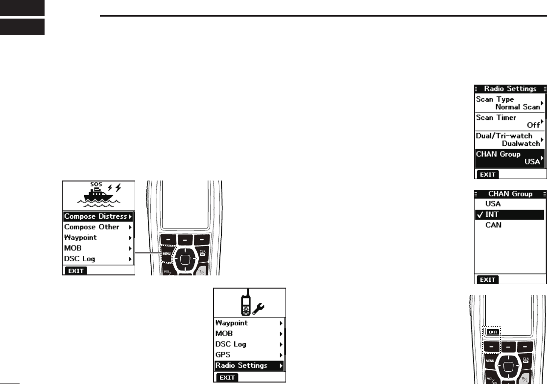
53
10 MENU SCREEN
■Using the Menu screen
The Menu screen is used to set items, select options, and
so on for the transceiver’s functions.
DUsing the Menu screen
Example: Setting the channel group to “INT.”
1. Push [MENU].
• The Menu screen is displayed.
3. Push[▲]or[▼]toselect“CHAN
Group,” and then push [ENT].
• The“CHANGroup”screenis
displayed.
2. Push[▲]or[▼]toselect“Radio
Settings,” and then push [ENT].
• The“RadioSettings”screenis
displayed.
LHoldingdown[▲]or[▼]sequentially
scrollsupordownthroughtheMenu
screen.
4. Push[▲]or[▼]toselect“INT,”
and then push [ENT].
• “INT” is set and the transceiver
returns to the previous screen.
L To exit the Menu screen, push the
softwarekeybelow[EXIT].
L To return to the previous screen,
push[CLR é].
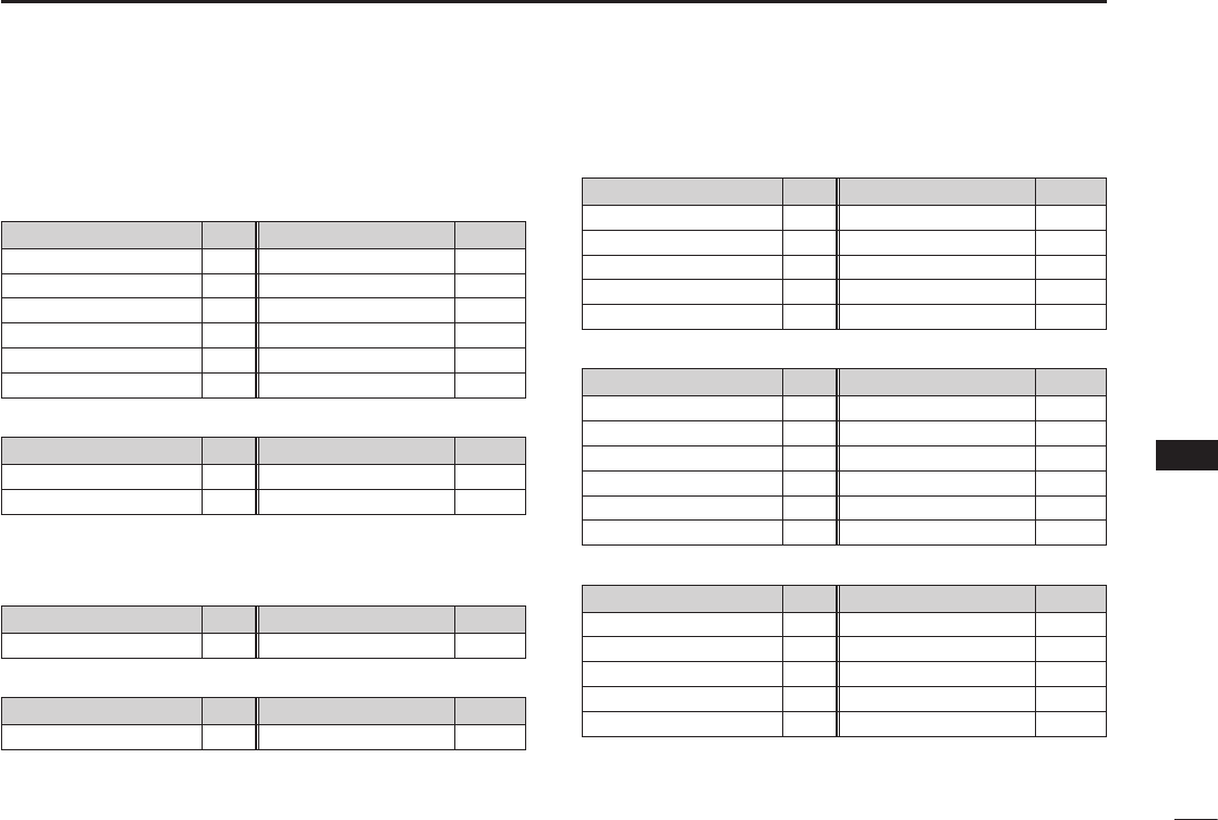
54
10
MENUSCREEN
1
2
3
4
5
6
7
8
9
10
11
12
13
14
15
16
■Menu screen items
TheMenuscreencontainsthefollowingitems.
Compose Distress
Item Ref. Item Ref.
Undesignated p. 23
Sinking
p. 23
Fire,Explosion p. 23
Adrift
p. 23
Flooding p. 23 AbandoningShip p. 23
Collision p. 23 Piracy p. 23
Grounding p. 23 ManOverboard p. 23
Capsizing p. 23 — —
Compose Other
Item Ref. Item Ref.
IndividualCall p. 25 AllShipsCall p. 29
GroupCall p. 28 TestCall p. 30
Waypoint (See pages 46 ~ 48 for details)
MOB (See pages 45 for details)
DSC Log
Item Ref. Item Ref.
Received p. 40 Transmitted p. 41
GPS/GNSS
Item Ref. Item Ref.
Status p. 50 Information p. 52
Radio Settings
Item Ref. Item Ref.
Scan Type* p. 55 Monitor p. 55
Scan Timer* p. 55 NoiseCancel p. 56
Dual/Tri-watch* p. 55 CallChannel p. 56
CHANGroup p. 55 FAVSettings p. 56
WXAlert* p. 55 RTIndicator p. 56
DSC Settings
Item Ref. Item Ref.
Position Input p. 42 UnreadReturn p. 43
Individual ID p. 42 MOBAutoSet p. 43
Group ID p. 42 AlarmStatus p. 43
AutoACK p. 42 CH70SQLLevel p. 44
CHAutoSwitch p. 42 DST at PW Off p. 44
DSCSwitch p. 42 LoopTest p. 44
Conguration
Item Ref. Item Ref.
Backlight p.57 UTCOffset p.57
DisplayContrast p.57 Inactivity Timer p.57
KeyBeep p.57 Float’n Flash p.57
KeyAssignment p.57 PowerSave p.57
Direction p.57 — —
Information (See pages 52 for details)
*Maynotbedisplayed,dependingonthetransceiverversion.

55
10 MENU SCREEN
■Radio Settings items
Scan Type (Default: —)
The transceiver has 2 scan types. Select Normal Scan and
Priority Scan.
• Normal Scan: Scans all Favorite channels in the selected
channel group.
• Priority Scan:SequentiallyscansallFavoritechannels,
whilemonitoringChannel16.
L The default setting differs, depending on the transceiver version.
Scan Timer (Default: Off)
You can use the Scan Timer to pause, or to resume after 5
seconds,whenasignalisdetected.
• On: When a signal is detected on a channel, the scan
pauses for 5 seconds, and then resumes. If the
signal disappears in less than 5 seconds, the scan
immediately resumes.
• Off: When a signal is detected on a channel, the scan
pauses until the signal disappears, and then resumes.
Dual/Tri-watch (Default:Dualwatch)
SelectDualwatchorTri-watch.
• Daulwatch: MonitorsChannel16whilereceivingon
another channel.
• Tri-watch: MonitorsChannel16andtheCallchannel
whilereceivingonanotherchannel.
LSee page 18 for details.
CHAN Group (Default: —)
Selectthesuitablechannelgroupforyouroperatingarea.
SelectINT,USA,CAN,DSC,orATISdependingonthe
transceiver version.
LSee page 12 for details.
WX Alert (Default: Off)
FortheUSA,Australian,andExportversions,anNOAA
broadcaststationtransmitsaWeatherAlerttonebeforeany
importantweatherinformation.
L“WX ”isdisplayedinsteadof“WX.”
L“WX ”blinksuntilyoupushakeyafterdetectinganalert.
• On with Scan: The preset Weather channels are
sequentiallycheckedwhilescanning.
• On:
The previously selected (last used) Weather
channelischeckedwhilescanning.
• Off: TheWeatherAlerttoneisnotdetected.
Monitor (Default: Push)
Holddown[VOL/SQL]for1secondtoturnONtheMonitor
function.Thesquelchopens.
Youcanselectwhetherthesquelchcloseswhenyourelease
[VOL/SQL],orwhenyoupushanykey.
• Push: Thesquelchstaysopenwhileholdingdown
[VOL/SQL].
• Hold: Thesquelchstaysopenuntilyoupushanykey.

56
10
MENUSCREEN
1
2
3
4
5
6
7
8
9
10
11
12
13
14
15
16
Noise Cancel (Default: Off)
TheNoiseCancelfunctionreducesrandomnoise
components in the received or transmitted signal. Set the
functionforbothreceivingandtransmitting.
RX
• Off: TheNoiseCancelfunctionisOFF.
• 1: Reducesrandomnoisecomponentsinthereceived
signal to approximately one half.
• 2: Reducesrandomnoisecomponentsinthereceived
signal to approximately one third.
• 3: Reducesrandomnoisecomponentsinthereceived
signal to approximately one tenth.
TX
• On: Reducesrandomnoisecomponentsinthetransmitted
signal to approximately one third.
• Off: TheNoiseCancelfunctionisOFF.
Call Chancel (Default: —)
YoucanchangeyourCallchannel.Thedefaultsetting
differs, depending on the transceiver version.
LSee page 13 for details.
FAV Settings
You can set all channels as Favorite channels, clear all
settings, or reset to default. By default, some channels
are preset. The Favorite channels differ, depending on the
transceiver version.
• Set All Channels:
Sets all channels as Favorite channels.
• Clear All Channels:ClearsallFavoritechannels.
• Set default: ResetsFavoritechannelstothe
default.
LSeepage17fordetails.
RT Indicator (Default: On)
SelectwhetherornottodisplaytheRadioTelephone
indicator(RT)whileintheRTmode.Thisindicatesthatwhile
RTisdisplayed,youcanmakeavoicecommunication,
exceptforaDSCcall.
• On: TheRTindicatorisdisplayed.
• Off: TheRTindicatorisnotdisplayed.
LWhen“On”isselected,“STBY”isdisplayedwhileinthestandby
mode,and“DSC”isdisplayedwhileintheDSCmode.

57
10 MENU SCREEN
■Conguration items
Backlight
Level (Default: 4)
Youcanadjustthebacklightbrightnessbetween1and7,or
OFF.ThebacklightautomaticallyturnsOFFafternokeyis
pushed for 5 seconds.
Continue Type (Default: Off)
Youcansetthebacklightondim,evenifthebacklightis
automaticallyturnedOFF.Thisfunctionenablesyoutosee
thedisplayinthedark,evenwhenthebacklightisOFF.
• Off: The function is turned OFF.
• Dim: Thescreenstaysdimlylit,evenifthebacklightis
turnedOFFafternokeyispushedfor5seconds.
LIfyouwanttoreducethebatteryconsumption,turnthisfunction
OFF.
Display Contrast (Default: 4)
Youcanadjustthedisplaycontrastlevelbetween1and8.
Oneisthelowestcontrastlevel,andeightisthehighest
contrast level.
Key Beep (Default: On)
Youcanselectwhetherornottosoundabeepwhenakey
is pushed.
• On: Soundsabeepwhenakeyispushed.
• Off: Nobeepsounds,forsilentoperation.
Key Assignment
Softkey 1~21
Youcanchangewhichsoftwarekeyfunctionstodisplay,and
theirorder.Youcanassignupto21softwarekeysatatime.
LTheusablesoftwarekeyfunctionsandtheirordermaydiffer,
depending on the transceiver version.
Set default
Selectthisitemtosetthesoftwarekeyfunctionorderas
default.
L The default setting may differ, depending on the transceiver
version.
Direction
Youcansetthedisplaytypeforthe“Compass,”“Navigation,”
and“PositionCheck”screen.
Compass (Default: N-UP)
• N-UP: The top of the compass represents North.
• AC-UP: The compass represents the direction of your
course heading.
Navigation (Default: N-UP)
• N-UP: The top of the “Navigation” screen represents North.
• AC-UP: The top of the “Navigation” screen represents the
direction of your course heading.
• WP-UP: The top of the “Navigation” screen represents the
destinationwaypoint.

58
10
MENUSCREEN
1
2
3
4
5
6
7
8
9
10
11
12
13
14
15
16
Position Check (Default: N-UP)
• N-UP: Thetopofthe“PositionCheck”screenrepresents
North.
• AC-UP: Thetopofthe“PositionCheck”screenrepresents
the direction of your course heading.
UTC Offset (Default: 00:00)
SettheoffsettimebetweenUniversalTimeCoordinated
(UTC)andyourlocaltimetobetween–14:00and+14:00(in
1 minute steps).
Inactivity Timer
The transceiver automatically returns to the operation screen
ifyoupushnokeyforthesetperiodoftimeforeachmode.
Not DSC Related (Default: 10 min)
Thissettingisforwhenthetransceiverdisplaysascreen
thatisnotrelatedtoDSC.
DSC Related (Default: 15 min)
Thissettingisforwhenthetransceiverdisplaysascreen
thatisrelatedtoDSC.
Distress Related (Default: Off)
Thissettingisforwhenthetransceiverdisplaysascreen
that is related to a Distress call.
RT Related (Default: 30 sec)
ThissettingisforwhenthetransceiverisintheRadio
Telephone mode.
Float’n Flash
The Float’n Flash function detects that the transceiver
has come in contact with water. When the function turns
ON, the backlight starts to blink to make it easy to find the
transceiver, even in the dark.
Function (Default: On)
• On: The Float’n Flash function is ON.
• Off: The Float’n Flash function is OFF.
Auto Off (Default: 20 sec)
Aftertakingthetransceiveroutofthewater,thebacklight
keepsblinkingforthissetperiodoftime.Setthetimeto
between0and30seconds(in10secondsteps).
Cycle (Default: 0.5 sec)
ThebacklightrepeatedlyturnsONorOFFinthesettime
cycle. Set the cycle to 0.5, 1, 2 or 4 seconds.
Alarm (Default: Off)
Selectwhetherornottosoundanalarmwhilethebacklight
blinkswhentheFloat’nFlashfunctionisturnedON.
• On: Analarmsoundswhilethebacklightblinks.
• Off: Noalarmsounds,evenwhentheFloat’nFlash
function is set to ON.
Power Save (Default: On)
Thisfunctionconservesbatterypower.Thepowersave
functionisautomaticallyturnedONwhennosignalisreceived
for 5 seconds.
TurnthePowerSavefunctionONorOFF.

59
11 BATTERY CHARGING
R DANGER! NEVER solder the battery terminals, or NEVER
modify the battery pack. This may cause heat generation, and the
battery may burst, emit smoke or catch re.
R DANGER! NEVER leave battery pack in places with
temperatures above +60˚C (+140˚F). High temperature buildup in
the battery, such as could occur near res or stoves, inside a
sun-heated vehicle, or in direct sunlight for long periods of time may
cause the battery to rupture or catch re. Excessive temperatures
may also degrade battery’s performance or shorten battery life.
R DANGER! NEVER strike or otherwise impact the battery. Do not
use the battery if it has been severely impacted or dropped, or if the
battery has been subjected to heavy pressure. Battery damage may
not be visible on the outside of the case. Even if the surface of the
battery does not show cracks or any other damage, the cells inside
the battery may rupture or catch re.
R DANGER! NEVER expose the battery to rain, snow, seawater, or
any other liquids. Do not charge or use a wet battery. If the battery
gets wet, be sure to wipe it dry before using.
R DANGER! NEVER place or leave battery packs near re. Fire or
heat may cause them to rupture or explode. Dispose of used battery
packs in accordance with local regulations.
R DANGER! NEVER use the battery with a transceiver for which
it is not specied. Never use a battery with any other equipment, or
for any purpose that is not specied in this instruction manual.
R DANGER! NEVER
let uid from inside the battery get in your
eyes. If it does, blindness can result. Rinse your eyes with clean
water, without rubbing them, and immediately go to a doctor.
R WARNING!
NEVER put the battery in a microwave oven,
high-pressure container, or in an induction heating cooker. This could
cause a re, overheating, or cause the battery to rupture.
R
WARNING! NEVER use the battery if it emits an abnormal odor,
heats up, or is discolored or deformed. If any of these conditions
occur, contact your Icom dealer or distributor.
R WARNING! NEVER let uid from inside the battery come in
contact with your body. It it does, immediately wash with clean water.
CAUTION: DO NOT use the battery pack out of the specied
temperature range.
• IC-M93D: –20°C ~ +60°C (–4°F ~ +140°F)
• IC-M93D EURO: –15˚C ~ +55˚C
(–10˚C ~ +55˚C for the Australian version)
• BP-285: –20°C ~ +60°C (–4°F ~ +140°F)
Using the battery out of its specied temperature range will reduce the
battery’s performance and battery life. Please note that the specied
temperature range of the battery may exceed that of the transceiver. In
such cases, the transceiver may not work properly because it is out of
its operating temperature range.
DBattery caution
Misuse of Li-ion batteries may result in the following hazards:
smoke, re, or the battery may rupture. Misuse can also cause
damage to the battery or degradation of battery’s performance.
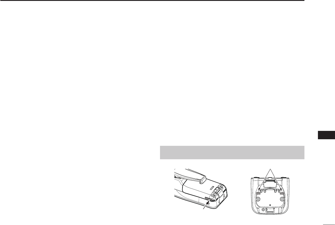
60
11
BATTERY CHARGING
1
2
3
4
5
6
7
8
9
10
11
12
13
14
15
16
CAUTION: Shorter battery life could occur if the battery is left fully
charged, completely discharged, or in an excessive temperature
environment (above +50°C (+122°F)) for an extended period of
time. If the battery pack must be left unused for a long time, it must
be detached from the transceiver after discharging. You may use
the battery pack until the remaining capacity is about half, then keep
it safely in a cool and dry place at the following temperature range:
–20˚C ~ +50˚C (–4˚F ~ +122˚F) (within a month)
–20˚C ~ +40˚C (–4˚F ~ +104˚F) (within three months)
–20˚C ~ +20˚C (–4˚F ~ +68˚F) (within a year)
BE SURE to replace the battery pack with a new one approximately
ve years after manufacturing, even if it still holds a charge. The inside
battery material will become weak after a period of time, even with
little use. The estimated number of times you can charge the battery
is between 300 and 500. Even when the battery appears to be fully
charged, the operating time of the transceiver may become short when:
• Approximately ve years have passed since the battery was
manufactured.
• The battery has been repeatedly charged.
DCharging caution
R DANGER! NEVER charge the battery pack in areas with
extremely high temperatures, such as near res or stoves, inside
a sun-heated vehicle, or in direct sunlight. In such environments,
the safety/protection circuit in the battery will activate, causing the
battery to stop charging.
R DANGER! NEVER charge the transceiver during a lightning
storm. It may result in an electric shock, cause a re or damage the
transceiver. Always disconnect the power adapter before a storm.
R WARNING! NEVER charge or leave the battery in the battery
charger beyond the specied time for charging. If the battery is
not completely charged by the specied time, stop charging and
remove the battery from the battery charger. Continuing to charge
the battery beyond the specied time limit may cause a re,
overheating, or the battery may rupture.
R WARNING! NEVER insert the transceiver (battery attached to
the transceiver) into the charger if it is wet or soiled. This could
corrode the battery charger terminals or damage the charger. The
charger is not waterproof.
NOTE: Charge the battery pack within the specied temperature
range: +10˚C ~ +45˚C (+50˚F ~ +113˚F). Otherwise, the charging
time will be longer, but the battery will not reach a full charge. While
charging, at a point after the temperature goes out of the specied
range, the charging will automatically stop.
NOTE: Be sure the slots on the battery pack are correctly aligned
with the guide tabs inside the battery charger.
Guide tabs
Slot
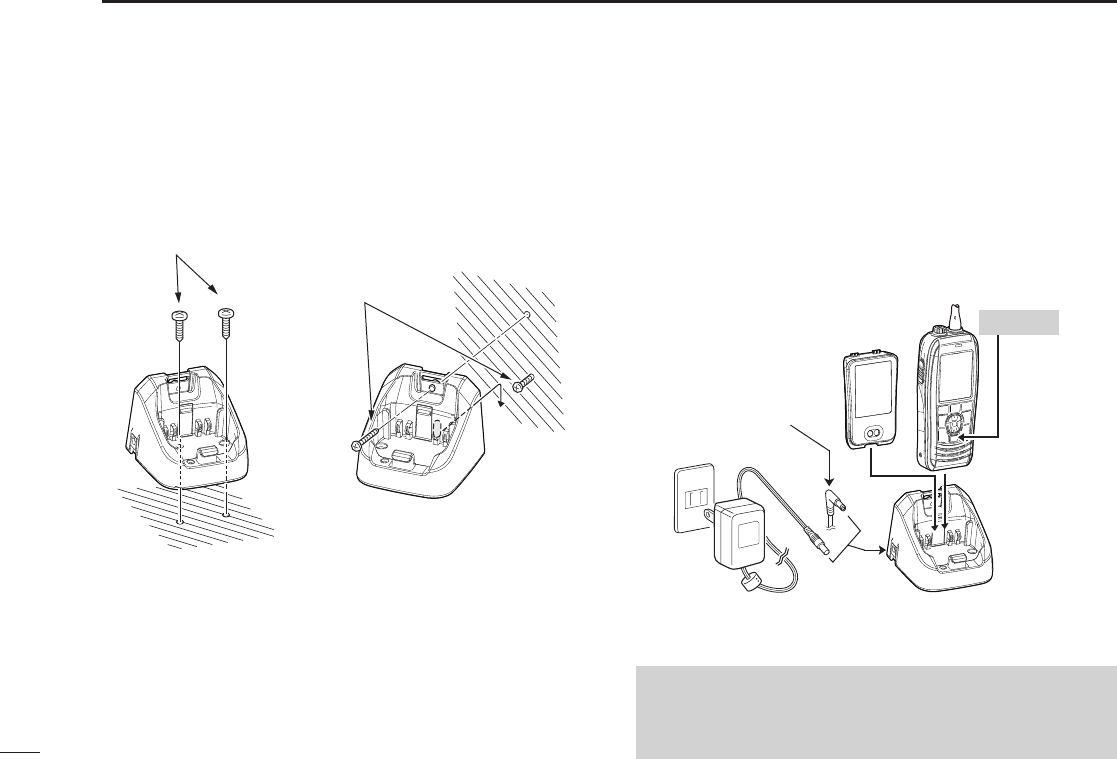
61
11 BATTERY CHARGING
DCharging with the BC-220 and BC-123S
You can charge Li-ion battery pack using the BC-220 and
BC-123S.
• Charging time: approximately 3 hours.
L You can also use the CP-25H cigarette lighter cable, or
OPC-515L dc power cable instead of the BC-123S.
■Regular battery charger
DInstalling the BC-220
On a desktop
q
w
e
Supplied screws
Supplied screws
On a wall
BC-123S*
power adapter
* A different type may be supplied, or
may not be supplied, depending on the
transceiver version.
CP-25H* (for a
12 V cigarette
lighter sockect) or
OPC-515L (for
a 12 V power
source) can be
used instead of
the BC-123S.
Battery
pack
Turn OFF
CAUTION: NEVER connect the OPC-515L to a power
source using reverse polarity. This will damage the battery
charger.
White line: + / Black line: _
BC-220
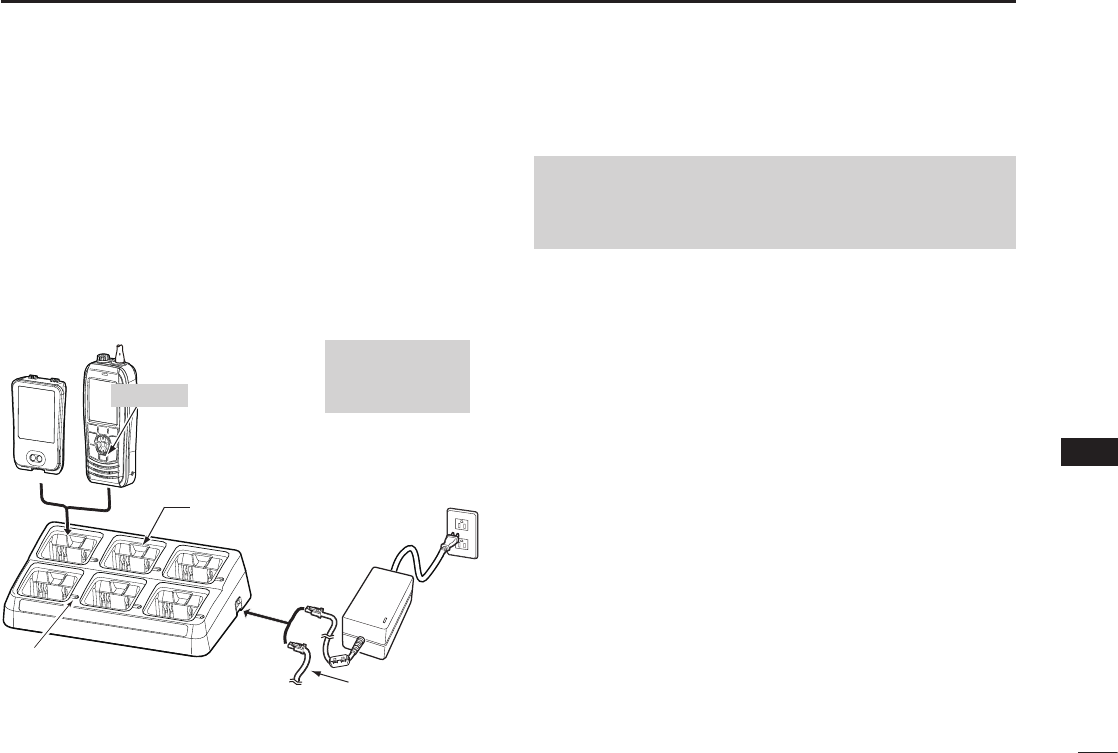
62
11
BATTERY CHARGING
1
2
3
4
5
6
7
8
9
10
11
12
13
14
15
16
■ Optional battery charger
D Rapid charging with the BC-214, BC-157S
and AD-133
The optional BC-214 with the BC-157S and AD-133
simultaneously charges up to 6 Li-ion battery packs.
• Charging time: approximately 3 hours.
L You can also use the OPC-656* dc power cable instead of the
BC-157S and AD-133.
CAUTION: NEVER reverse the polarity when connecting
the power cable to a power source. This will damage the
battery charger.
Red line: + / Black line: _
Battery
pack
Turn OFF
The charger
adapters
(AD-133) are
installed in each
slot. The type
of the charger
adapter differs,
depending on
the version of
the BC-214.
NEVER transmit
near the BC-214 or
the power adapter
while charging.
BC-157S ac adapter
may not be supplied,
depending on
the version.
Status indicator
(Individual indicators) OPC-656*
*OPC-656 dc power cable
Connect to a DC power source (12 ~ 16 V/at least 7 A)
BC-157S
BC-214
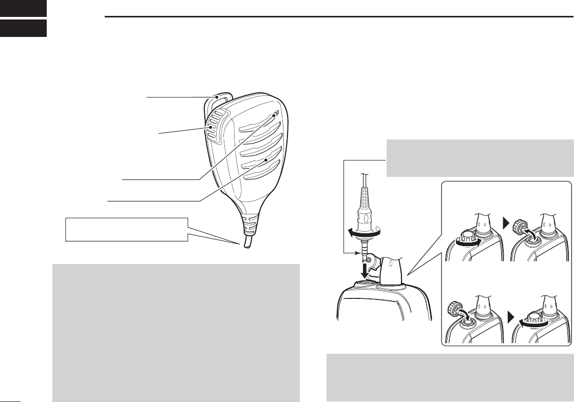
63
12 OPTIONAL SPEAKER MICROPHONE
■About the HM-165
NOTE:
• NEVER immerse the connector in water. If the connector
becomes wet, be sure to dry it BEFORE connecting it to
the transceiver.
• If the audio sound becomes mufed, remove any water that
may be inside the speaker grill and/or microphone hole.
• The microphone is near the top of the speaker microphone.
To maximize the readability of your transmitted signal,
hold the microphone 5 to 10 cm (2 to 4 inches) from your
mouth, and then speak at your normal voice level.
• The DSC alarms sound from the transceiver, even while
the speaker microphone is attached.
■Attaching the HM-165
1. Turn OFF the transceiver.
2. Insert the speaker microphone into the connector, and
then screw it tight, as shown below.
LBe careful not to cross-thread the connection.
Alligator type clip
Attaches to your shirt,
collar, pocket, and so on.
PTT switch
Push to transmit.
Release to receive.
Microphone
Speaker
Turn OFF the transceiver, when
connecting the HM-165.
NOTE: KEEP the jack cover attached when the speaker-
microphone is not connected. Otherwise, water will get into
the transceiver, and the terminals will become rusty, or if the
connector gets wet, the transceiver may not work properly.
CAUTION: Firmly attach the speaker
microphone jack to prevent loss, or water
immersion into the connector.
Detaching:
Rotate the jack cover, and then
detach.
Attaching:
Attach the jack cover, and then
rmly rotate it.

64
13
TROUBLESHOOTING
1
2
3
4
5
6
7
8
9
10
11
12
13
14
15
16
PROBLEM POSSIBLE CAUSE SOLUTION REF.
You cannot turn ON the
transceiver.
• The Battery is exhausted or over
discharged.
• The Battery pack is not correctly attached.
• Recharge the battery pack.
• Correctly attach the battery pack.
p. 61
p. 2
Little or no sound
comes from the
speaker.
• The squelch level is set too high.
• The volume level is set too low.
• The speaker has been exposed to water.
• Water has entered to the speaker
microphone connector.
• Set the squelch to the threshold point.
• Set the volume to a suitable level.
• Remove the water using the AquaQuake
function.
• Dry the speaker microphone connector.
p. 13
p. 15
–
You cannot transmit
• Some channels are preset for low power
or receive only by regulations.
• The battery is exhausted.
• The battery is overcharged.
• The output power is set to low.
• Change channels.
• Recharge the battery pack.
• Conrm that the battery voltage is correct.
• Push the software key below to select
high power.
p. 14
p. 61
p. 5
Scan does not start • Favorite channels are not set. • Set the Favorite channels. p. 17
No beeps sound • Key Beep is set to OFF. • Turn ON the Key Beep on the
“Conguration” screen.
p. 57
You cannot send DSC
calls
• MMSI (DSC self ID) code is not entered.
• DSC Switch is set to OFF.
• Enter the MMSI (DSC self ID) code.
• Turn ON the DSC Switch in the Menu.
p. 9
p. 42
You cannot receive
GPS position data
• The built-in GPS antenna is obstructed,
which interrupts the GPS signals from the
satellites.
• Use the transceiver in a place where
nothing interrupts the satellite signal.
–

65
14 SPECIFICATIONS AND OPTIONS
■Specications
IC-M93D
DGeneral
• Frequency coverage: TX 156.025 ~ 157.425 MHz
RX 156.050 ~ 163.275 MHz
• Mode: FM (16K0G3E), DSC (16K0G2B)
• Operating temperature range: –20°C ~ +60°C (–4°F ~ +140°F)
• Current drain (approximately): Tx (5 W) 1.5 A
Tx (1 W) 0.7 A
RX maximum audio
0.25 A (External)
0.45 A (Internal)
• Power supply requirement:
7.2 V DC nominal (negative ground)
• Frequency stability: ±10 ppm
• Antenna impedance: 50 ˘ nominal
• Dimensions (approximately): 57 (W) × 144.6 (H) × 38.5 (D) mm
(Projections not included) 2.2 (W) × 5.7 (H) × 1.5 (D) inches
• Weight (approximately): 265 g/9.3 oz with BP-285
DTransmitter
• Output power: 5 W/1 W
• Modulation system: Variable reactance frequency
modulation
• Maximum frequency deviation: ±5.0 kHz
• Adjacent channel power: 70 dB
• Spurious emissions (typical): –68 dBc
DReceiver
• Sensitivity (typical): 0.25 µV (12 dB SINAD)
• Squelch sensitivity (threshold, typical):
0.25 µV
• Intermodulation rejection ratio: 70 dB (typical)
•
Spurious response rejection ratio:
70 dB (typical)
• Adjacent channel selectivity: 70 dB (typical)
• Audio output power (at 10% distortion):
0.35 W typical (External)
with an 8 ˘ load
0.9 W typical (Internal) with a
12 ˘ load at 1 kHz
IC-M93D EURO
DGeneral
• Frequency coverage: TX 156.000 ~ 161.450 MHz
(156.000 ~ 161.600 MHz for Dutch version)
Rx 156.000 ~ 163.425 MHz
• Mode: FM (16K0G3E), DSC (16K0G2B)
• Operating temperature range: –15°C ~ +55°C
• Current drain (approximately): TX (5 W) 1.5 A
TX (1 W) 0.7 A
RX maximum audio
0.25 A (External)
0.45 A (Internal)
• Power supply requirement:
7.2 V DC nominal (negative ground)
• Frequency stability: ±1.5 kHz
• Antenna impedance: 50 ˘ nominal
• Dimensions (approximately): 57 (W) × 144.6 (H) × 38.5 (D) mm
(Projections not included)
• Weight (approximately): 265 g with BP-285

66
14
SPECIFICATIONS AND OPTIONS
1
2
3
4
5
6
7
8
9
10
11
12
13
14
15
16
DTransmitter
• Output power: 5 W/1 W
• Modulation system: Variable reactance frequency
modulation
• Maximum frequency deviation: ±5 kHz
• Adjacent channel power: 70 dB
• Spurious emissions: 0.25 µW
DReceiver
• Sensitivity (typical): –6 dBµ emf at 20 dB SINAD
• Squelch sensitivity (threshold, typical):
–6 dBµ emf
• Intermodulation rejection ratio: 68 dB
•
Spurious response rejection ratio:
70 dB
• Adjacent channel selectivity: 70 dB
• Audio output power (at 10% distortion
):
0.2 W (External) with an
8 ˘ load
0.9 W typical (Internal) with a
12 ˘ load
at 1 kHz
IC-M93D EURO (Australian version)
DGeneral
• Frequency coverage: TX 156.025 ~ 157.425 MHz
RX 156.300 ~ 162.025 MHz
• Mode: FM (16K0G3E), DSC (16K0G2B)
• Operating temperature range: –10°C ~ +55°C
• Current drain (approximately): TX (5 W) 1.5 A
TX (1 W) 0.7 A
RX maximum audio
0.25 A (External)
0.45 A (Internal)
• Power supply requirement:
7.2 V DC nominal (negative ground)
• Frequency stability: ±10 ppm (–10°C ~ +55°C)
• Antenna impedance: 50 ˘ nominal
• Dimensions (approximately): 57 (W) × 144.6 (H) × 38.5 (D) mm
(Projections not included)
• Weight (approximately): 265 g/9.3 oz with BP-285
DTransmitter
• Output power: 5 W/1 W
• Modulation system: Variable reactance frequency
modulation
• Maximum frequency deviation: ±5.0 kHz
• Adjacent channel power: 70 dB
• Spurious emissions (typical): 0.25 µW
DReceiver
• Sensitivity (typical): –6 dBµ emf (20 dB SINAD)
• Squelch sensitivity (threshold, typical):
–6 dBµ emf
• Intermodulation rejection ratio: 65 dB
•
Spurious response rejection ratio:
65 dB
• Adjacent channel selectivity: 65 dB
• Audio output power (at 10% distortion):
0.2 W (External) with an 8 ˘ load
0.9 W typical (Internal) with a
12 ˘ load at 1 kHz
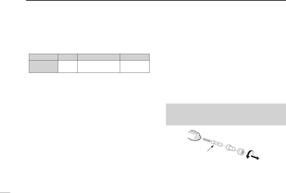
67
14 SPECIFICATIONS AND OPTIONS
■Options
DBattery pack
• BP-285 Li-ion battery pack
Battery pack Voltage Capacity Battery life*
BP-285 7.2 V 1485 mAh (minimum)
1570 mAh (typical) 9 hours
* The operating periods are calculated under the following
conditions; TX : RX : Standby = 5 : 5 : 90
(Power save : ON/ while valid GPS position data is received)
DChargers
• BC-220 rapid charger + BC-123S ac adapter
For rapid charging of battery pack.
(Charging time: approximately 3 hours)
• BC-214 rapid charger + AD-133 charger adapter (6 pcs.)
+ BC-157S ac adapter
For rapid charging of 6 battery packs.
(Charging time: approximately 3 hours)
DDC cables
• opc-515l/opc-656 dc power cable
For charging of the battery packs using a 12 V DC power source
instead of the AC adapter.
(OPC-515L for BC-220 : OPC-656 for BC-214)
DOther
• HM-165/HM-228 speaker microphone
Full sized waterproof speaker microphone including alligator type
clip to attach to your shirt or collar.
• FA-SC59V flexible antenna
• MB-133 belt clip
• MB-96F/MB-96FL leather belt hanger
• CP-25H cigarette lighter cable
For charging with the BC-220 charger through a 12 V cigarette
lighter socket.
NOTE: The CP-25H is equipped with a 1 A fuse. If the fuse
blows, repair the problem, then replace it with a new rated
fuse. DO NOT use fuses with amp ratings other than the ratings
written below.
CP-25H: (1 A /250 V)
Fuse
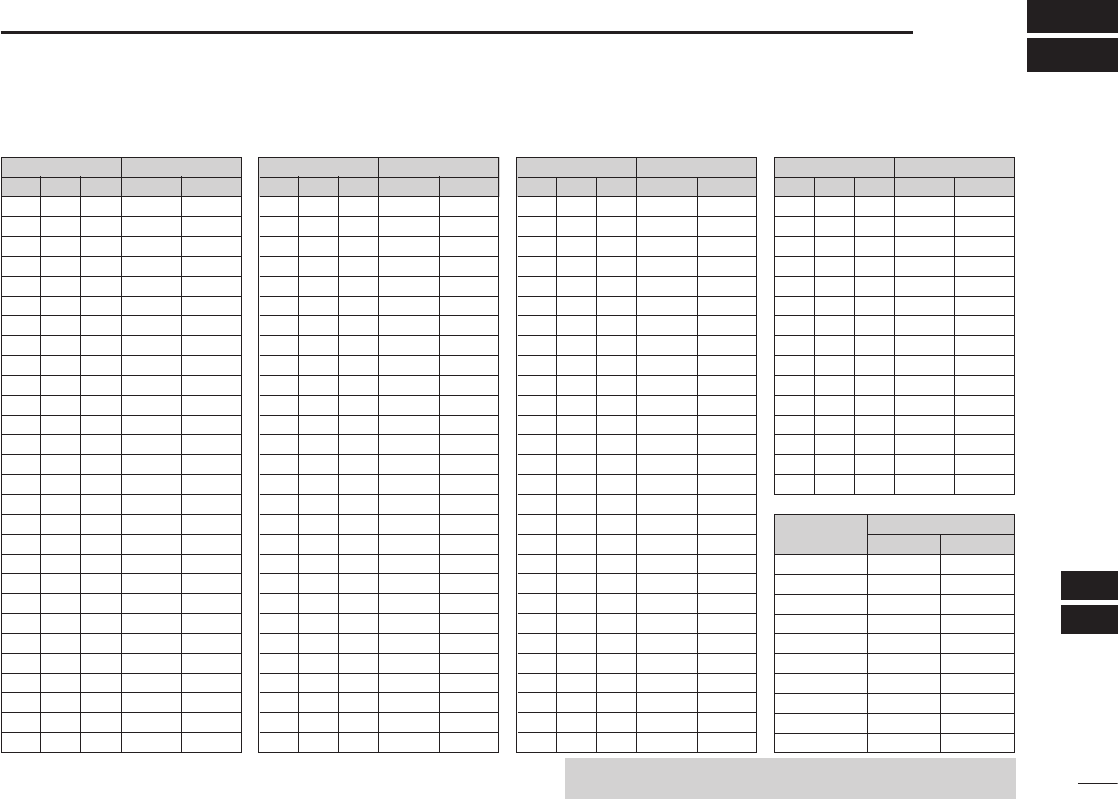
68
15
CHANNEL LIST
1
2
3
4
5
6
7
8
9
10
11
12
13
14
15
16
NOTE: Simplex channels, 3, 21, 23, 61, 64, 81, 82, and 83 CANNOT
be lawfully used by the general public in USA waters.
DFor IC-M93D and IC-M93D EURO (Australia)
Channel number Frequency (MHz)
03 156.150 160.75003
03A 156.150 156.150
156.200 160.80004
02 156.100 160.70002
04A 156.200 156.200
156.250 160.85005
05A 05A 156.250 156.250
06 06 156.300 156.30006
156.350 160.95007
07A 07A 156.350 156.350
08 08 156.400 156.40008
09 09 156.450 156.45009
10 10 156.500 156.50010
11 11 156.550 156.55011
12 12 156.600 156.60012
13*113*1
156.650 156.650
13
14 14
156.700 156.700
14
15*115*1
156.750 156.750
15*1
16 16
156.800 156.800
16
17*117*1
156.850 156.850
17
156.900 161.500
18
18A 18A
156.900 156.900
156.950 161.550
19
19A 19A 156.950 156.950
20 20*1157.000 161.60020
20A 157.000 157.000
01A 156.050 156.050
USA
01
156.050 160.65001
CAN
Transmit Receive
INT
Channel number Frequency (MHz)
157.100 161.70022
22A 22A 157.100 157.100
23 157.150 161.75023
21b Rx only 161.650
23A 157.150 157.150
24 24 157.200 161.80024
25 25 157.250 161.85025
25b Rx only 161.850
26 26 157.300 161.90026
27 27 157.350 161.95027
28 28 157.400 162.00028
28b Rx only 162.000
60 156.025 160.62560
156.075 160.67561
61A 61A 156.075 156.075
156.125 160.72562
62A 156.125 156.125
156.175 160.77563
63A 156.175 156.175
64 156.225 160.82564
64A 64A 156.225 156.225
156.275 160.87565
65A 65A 156.275 156.27565A
156.325 160.92566
66A 66A*1156.325 156.32566A
67*167 156.375 156.37567
21A 21A 157.050 157.050
USA
21 157.050 161.65021
CAN
Transmit Receive
INT
Channel number Frequency (MHz)
71 71 156.575 156.57571
72 72 156.625 156.62572
73 73 156.675 156.67573
70*470*4156.525 156.52570*4
74 74 156.725 156.72574
75*175*1156.775 156.77575*1
76*176*1156.825 156.82576*1
77*177*1156.875 156.87577
156.925 161.52578
78A 78A 156.925 156.925
156.975 161.57579
79A 79A 156.975 156.975
157.025 161.62580
80A 80A 157.025 157.025
157.075 161.67581
81A 81A 157.075 157.075
157.125 161.72582
82A 82A 157.125 157.125
83 157.175 161.77583
83A 83A 157.175 157.175
83b Rx only 161.775
84 84 157.225 161.82584
84A 157.225 157.225
85 85 157.275 161.87585
85A 157.275 157.275
86 86 157.325 161.92586
69 69 156.475 156.47569
68
USA
68 156.425 156.42568
CAN
Transmit Receive
INT
Channel number Frequency (MHz)
88 88 157.425 162.02588
88A 157.425 157.425
161.975 161.975A1*2
87A 157.375 157.375
162.025 162.025A2*2
87 87 157.375 161.97587
86A
USA
157.325 157.325
CAN
Transmit Receive
INT
Frequency (MHz)
RX only 162.425
RX only 162.450
RX only 162.500
RX only 162.475
RX only 162.525
RX only 161.650
RX only 161.775
RX only 163.275
RX only 162.400
RX only 162.550
Transmit Receive
WX channel
4
5
6
3
7
8
9
10
2
1
156.950
1019*3
157.000
1020*3
156.925
1078*3
156.975
156.950
157.000
156.925
156.975
1079*3
*1 Low power only *2 For only the Australian version
*3 For only the USA version *4 DSC operation only

69
15 CHANNEL LIST
DFor IC-M93D EURO
CH Frequency (MHz) CH
Transmit
Receive
Frequency (MHz)
Transmit
Receive
CH Frequency (MHz)
Transmit
Receive
CH Frequency (MHz)
Transmit
Receive
CH Frequency (MHz)
Transmit
Receive
CH Frequency (MHz)
Transmit
Receive
CH Frequency (MHz)
Transmit
Receive
01 156.050 160.650 11 156.550 156.550 21 157.050 161.650 61 156.075 160.675 71 156.575 156.575 81 157.075 161.675 1019
*4
1020
*4
1078
*4
1079
*4
2020
*4
2078
*4
2079
*4
2019
*4
156.950
157.000
156.925
156.975
161.550
161.600
161.525
161.575 161.575
161.525
161.600
161.550
156.975
156.925
157.000
156.950
02 156.100 160.700 12 156.600 156.600 22 157.100 161.700 62 156.125 160.725 72 156.625 156.625 82 157.125 161.725
03 156.150 160.750 13 156.650 156.650 23 157.150 161.750 63 156.175 160.775 73 156.675 156.675 83 157.175 161.775
04 156.200 160.800 14 156.700 156.700 24 157.200 161.800 64 156.225 160.825 74 156.725 156.725 84 157.225 161.825
05 156.250 160.850 15*1156.750 156.750 25 157.250 161.850 65 156.275 160.875
75*
3
156.775 156.775 85 157.275 161.875
06 156.300 156.300 16 156.800 156.800 26 157.300 161.900 66 156.325 160.925
76*
3
156.825 156.825 86 157.325 161.925
07 156.350 160.950 17*1156.850 156.850 27 157.350 161.950 67 156.375 156.375 77 156.875 156.875 87 157.375 157.375
P4*2
161.425 161.425
88 157.425 157.425
08 156.400 156.400 18 156.900 161.500 28 157.400 162.000 68
69
156.425 156.425 78 156.925 161.525
09 156.450 156.450 19 156.950 161.550
37A*
2
157.850 157.850 156.475 156.475 79 156.975 161.575
10 156.500 156.500 20 157.000 161.600 60 156.025 160.625
70
*
5
156.525 156.525 80 157.025 161.625
● International channels
*1 Channels 15 and 17 may also be used for on-board communications
provided the effective radiated power does not exceed 1 W, and subject
to the national regulations of the administration concerned when these
channels are used in its territorial waters.
*2 UK Marina Channels: M1=37A (157.850 MHz), M2=P4 (161.425 MHz) for
UK version only.
*3
The output power of channels 75 and 76 are limited to low power (1 W)
only. The use of these channels should be restricted to navigation-related
communications only and all precautions should be taken to avoid harmful
interference to channel 16, for example by means geographical separation.
*4
For only the Dutch version
*5
DSC operation only

70
15
CHANNEL LIST
1
2
3
4
5
6
7
8
9
10
11
12
13
14
15
16
DFor IC-M93D EURO
NOTE: Simplex channels, 3, 21, 23, 61, 64, 81, 82, and 83 CANNOT be lawfully used by the general public in USA waters.
Frequency (MHz)
Transmit Receive
156.050 156.050 156.600 156.600 157.100 157.100 156.225 156.225 156.775 156.775
156.825 156.825
156.875 156.875 157.325 161.925
- - -- - - 156.650 156.650 157.150 157.150 156.275 156.275
156.925 156.925 157.325 157.325
156.150 156.150 156.700 156.700 157.200 161.800 156.325 156.325
156.975 156.975 157.375 161.975
- - -- - - 156.750 156.750 157.250 161.850 156.375 156.375
157.025 157.025 157.375 157.375
156.250 156.250 156.800 156.800 157.300 161.900 156.425 156.425
157.075 157.075 157.425 162.025
156.300 156.300 156.850 156.850 157.350 161.950 156.475 156.475
157.125 157.125 157.425 157.425
161.425 161.425
156.350 156.350 156.900 156.900 157.400 162.000 156.525 156.525
157.175 157.175
156.400 156.400 156.950 156.950 157.850 157.850 156.575 156.575
157.225 161.825
156.450 156.450 157.000 161.600 156.075 156.075 156.625 156.625
157.225 157.225
156.500 156.500 157.000 157.000 - - -- - - 156.675 156.675
156.550 156.550 157.050 157.050 156.175 156.175 156.725 156.725
157.275 161.875
157.275 157.275
12
13*1
20A
21A
20
19A
18A
17*1
16
15*1
14
22A
23A
- -
63A
61A
37A*2
28
27
26
25
24
64A
65A
73
74
72
71
70*3
69
68
67*1
66A
75*1
76*1
84
84A
83A
82A
81A
80A
79A
78A
77*1
85
85A
P4*2
88A
88
87A
87
86A
86
01A
- -
10
11
09
08
07A
06
05A
- -
03A
CH Frequency (MHz)
Transmit Receive
CH Frequency (MHz)
Transmit Receive
CH Frequency (MHz)
Transmit Receive
CH Frequency (MHz)
Transmit Receive
CH Frequency (MHz)
Transmit Receive
CH
● USA channels (for UK version only)
*1 Low power only
*2 UK Marina Channels: M1=37A (157.850 MHz), M2=P4 (161.425 MHz) for UK version only.
*3
DSC operation only
71
16 SAFETY TRAINING INFORMATION
Your Icom radio generates RF electromagnetic energy while
transmitting. This radio is designed for and classied as for
“Occupational Use Only.” This means it must be used only
during the course of employment by individuals aware of
the hazards, and the ways to minimize such hazards. This
radio is NOT intended for use by the “General Population”
in an uncontrolled environment. This radio has been tested
and complies with the FCC and IC RF exposure limits for “Occupational Use
Only”. In addition, your Icom radio complies with the following Standards and
Guidelines with regard to RF energy and electromagnetic energy levels and
evaluation of such levels for exposure to humans:
• FCC KDB Publication 447498 D03, Evaluating Compliance with FCC
Guidelines for Human Exposure to Radio Frequency Electromagnetic
Fields.
• American National Standards Institute (C95.1-1992), IEEE Standard
for Safety Levels with Respect to Human Exposure to Radio Frequency
Electromagnetic Fields, 3 kHz to 300 GHz.
• American National Standards Institute (C95.3-1992), IEEE Recommended
Practice for the Measurement of Potentially Hazardous Electromagnetic
Fields– RF and Microwave.
• The antennas, batteries, belt clips, speaker microphone, and other
accessories that are listed in “OPTIONS” are authorized for use with this
product. Use of accessories other than those specied may result in RF
exposure levels exceeding the FCC and IC requirements for wireless RF
exposure.; Belt Clip (MB-133), Rechargeable Li-ion Battery Pack (BP-285).
• Health Canada Safety Code 6 - Limits of Human Exposure to
Electromagnetic Energy in the Frequency Range from 3 kHz to 300 GHz.
To ensure that your expose to RF electromagnetic
energy is within the FCC and IC allowable limits for
occupational use, always adhere to the following
guidelines:
• DO NOT operate the radio without a proper antenna attached, as this
may damage the radio and may also cause you to exceed FCC and IC RF
exposure limits. A proper antenna is the antenna supplied with this radio by
the manufacturer or an antenna specically authorized by the manufacturer
for use with this radio.
• DO NOT transmit for more than 50% of the total radio use time (“50%
duty cycle”). Transmitting more than 50% of the time can cause FCC and
IC RF exposure compliance requirements to be exceeded. The radio is
transmitting when the TX icon is displayed. You can cause the radio to
transmit by pushing the “PTT” switch.
• ALWAYS keep the antenna at least 2.5 cm (1 inch) away from the body
when transmitting, and only use the Icom belt-clips listed in “OPTIONS”
when attaching the radio to your belt, or other place, to ensure FCC and IC
RF exposure compliance requirements are not exceeded.
The information listed above provides the user with the information needed
to make him or her aware of RF exposure, and what to do to assure that this
radio operates within the FCC and IC RF exposure limits of this radio.
Electromagnetic Interference/Compatibility
During transmissions, your Icom radio generates RF energy that can possibly
cause interference with other devices or systems. To avoid such interference,
turn off the radio in areas where signs are posted to do so. DO NOT operate
the transmitter in areas that are sensitive to electromagnetic radiation such as
hospitals, aircraft, and blasting sites.
WARNING
CAUTION

72
INDEX
1
2
3
4
5
6
7
8
9
10
11
12
13
14
15
16
Accessories .............................. 2
Alarm Status (DSC Settings) ....43
All Ships call
Receiving ...........................37
Sending ..............................29
AquaQuake function ................15
ATIS ID ....................................10
Auto ACK (DSC Settings) ........42
Backlight (Conguration) ........ 57
Battery
Charger, optional ................62
Charger, regular .................61
Indicator ...............................6
Installing/charging ..............61
Call Chancel
Radio Settings .................... 56
Selecting ............................11
Setting ................................13
CH 70 SQL Level
(DSC Settings) ....................44
CHAN Group (Radio Settings)
...55
Channel
Favorite ..............................17
Group .................................12
List .....................................68
Name, editing ..................... 15
Selecting ............................11
Channel 16 ..............................11
CH Auto Switch (DSC Settings)
...42
Compass .................................50
Conguration items..................57
Direction (Conguration) .......... 57
Display
Contrast (Conguration) ......57
Description ...........................5
Distress call
Sending ..............................22
Receiving ...........................34
Cancel call .........................24
Regular call ........................23
Simple call .......................... 22
DSC
Address ID .........................19
Receiving ...........................35
Sending ..............................25
Log, received .....................40
Log, sent ............................41
Settings ..............................42
Switch (DSC Settings) ......... 42
DST at PW Off (DSC Settings)
...44
Dual/Tri-watch (Radio Settings)
.. 55
Dualwatch ................................18
Favorite channels, setting ......17
FAV Settings (Radio Settings) ... 56
Float’n Flash (Conguration) ....58
GPS/GNSS ............................50
Information screen .............52
Status screen .....................50
Group call
Receiving ...........................36
Sending ..............................28
Group ID
Deleting/Entering ...............20
(DSC Settings) ...................42
HM-165, about/attaching ........ 63
Inactivity Timer (Conguration)
.. 58
Individual
Acknowledgement ..............26
Call, receiving ....................35
Call, sending ......................25
ID, deleting ......................... 20
ID (DSC Settings) ..............42
ID, entering ........................19
Information screen ...................52
Key Assignment
(Conguration).....................57
Key Beep (Conguration) .........57
Lock function ..........................14
Loop Test (DSC Settings) .........44
Menu
Items ..................................54
Using .................................. 53
MMSI code, entering .................9
MOB (Man OverBoard)............45
Auto Set .............................43
Deleting ..............................45
Entering .............................. 45
Navigating ..........................45
Monitor
Function .............................15
(Radio Settings) .................55
Navigation ..............................48
Noise Cancel (Radio Settings) .. 56
Options ...................................67
Panel description ...................... 4
Position
Check (Conguration) ............
58
Entering .............................. 21
Input (DSC Settings) ..........42
Reply call, sending ............. 32
Request call, receiving ....... 38
Power Save (Conguration) ....58
Radio Settings .........................55
Receiving (basic) .....................14
RT Indicator (Radio Settings) .... 56
Scan
Normal/Priority ...................16
Starting ...............................17
Timer (Radio Settings) ......... 55
Type (Radio Settings) ..........55
Types .................................16
Software keys ............................7
Specications ..........................65
Squelch level ...........................13
Test Acknowledgement
Receiving ...........................40
Sending ..............................31
Test call
Receiving ...........................39
Sending ..............................30
Time, entering .......................... 21
Transmitting (basic) .................14
Tri-watch ..................................18
Troubleshooting .......................64
Unread Return (DSC Settings)
... 43
UTC Offset (Conguration) .......58
Volume level............................13
Waypoint .................................46
Adding/Deleting/Editing ......48
Entering .............................. 46
Entering, received position
... 47
Name, entering ..................46
Navigating ..........................47
Screen ................................47
Weather
Alert/channels ....................12
Alert (Radio Settings) ......... 55
1-1-32 Kamiminami, Hirano-ku, Osaka 547-0003, Japan
< Intended Country of Use >
AT
FI
IT
PL
GB
RO
BE
FR
LV
PT
IS
TR
CY
DE
LT
SK
LI
HR
CZ
GR
LU
SI
NO
DK
HU
MT
ES
CH
EE
IE
NL
SE
BG
A-7316H-1EX
Printed in Japan
© 2016 Icom Inc.
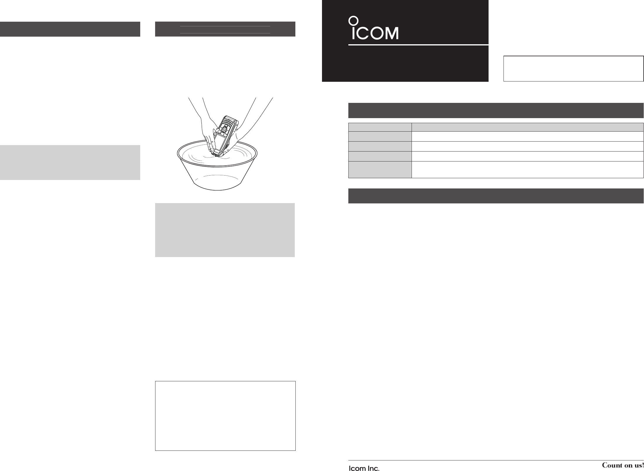
R DANGER! NE JAMAIS connecter les bornes du pack
batterie en court-circuit.
R DANGER! NE JAMAIS utiliser la radio près d'amorces
électriques non blindées ni dans une atmosphère explosive.
R DANGER! Utiliser et charger exclusivement les packs
batteries Icom spéci és avec les portatifs Icom ou un
chargeurs Icom. Seuls les packs batterie Icom sont testés
et homologués pour une utilisation avec les radios Icom ou
être chargés avec les chargeurs Icom. L'utilisation de packs
batterie ou de chargeurs tiers ou de contrefaçon peut être à
l'origine de fumées, d'incendie ou faire éclater la batterie.
R AVERTISSEMENT! NE JAMAIS utiliser l’appareil avec
un casque ou d’autres accessoires audio réglés sur un
niveau sonore élevé. Les spécialistes de l'audition mettent
en garde contre toute utilisation prolongée à niveau sonore
élevé. Si vous entendez une sonnerie baissez le niveau
sonore ou interrompez l'utilisation.
MISE EN GARDE: NE JAMAIS de nettoyer l’appareil
avec des produits chimiques telsque l’essence ou l’alcool
susceptibles d’endommager la surface de la radio.
MISE EN GARDE: NE JAMAIS tenir l’émetteur-récepteur
par l’antenne pour le transport.
MISE EN GARDE: véri er que l'antenne exible, batterie
et cache de la prise sont solidement xés à la radio, et que
l'antenne et la batterie sont secs avant de xation. Si vous
exposez à l'intérieur de la radio à la poussière ou à l'eau, la
radio sera remarquablement endommagé.
ÉVITER
d’utiliser ou de laisser la radio en plein soleil ou a une
température ambiante inférieure a –20°C (–4°F) ou supérieure a
+60°C (+140°F). Les opérations de base de la radio sont garantis
dans la plage de température de fonctionnement spéci ée.
Cependant, l'écran LCD peut ne pas fonctionner correctement
après avoir été placés dans des zones extrêmement froides, ou
une icône apparaît lors du fonctionnement de la radio pendant
une longue période de temps.
NE PAS modi er la radio. Les spéci cations peuvent
changer et puis ne pas se conformer aux exigences d'un
règlement correspondu. La garantie du radio ne couvre pas
les problèmes résultant d'une modi cation non autorisée.
ATTENTION! La radio chauffe en cas d’utilisation continue
sur une longue durée.
ATTENTION! La radio répond IPX7* exigences de
protection étanche à l'eau. Mais lorsque la radio est tombé
vers le bas, étanche à la protection imperméable à l'eau ne
peuvent pas être garantis, parce que le cas de la radio ou le
joint d'étanchéité peuvent être endommagés.
* Seulement lorsque le chapeau de la prise haut-parleur/
microphone, l'option HM-165 ou HM-228 est xé.
Même lorsque l’émetteur-récepteur est mis hors tension,
un courant de très faible intensité circule dans ses circuits.
Retirez la batterie de la radio quand ne pas l'utiliser pendant
une longue période. Sinon, la batterie sera déchargée, et
devra être rechargée ou remplacée.
Assurez-vous de couper l'alimentation de la radio avant de
brancher l'équipement fourni ou en option.
ATTENTION! Même si le niveau de volume est bas , les
bips du Float 'n Flash, DSC alarme et fonctions AquaQuake
sont très bruyants.
VEILLEZ l'émetteur-récepteur est hors tension avant de
connecter l'équipement fourni ou en option.
PRÉCAUTIONS
A-7316H-2US Printed in Japan
© 2016 Icom Inc.
1-1-32 Kamiminami, Hirano-ku, Osaka 547-0003, Japan
- 4 -
Merci d’avoir choisi un produit Icom.
LIRE TOUTES LES PRÉCAUTIONS soigneuse-
ment et intégralement avant d’utiliser la radio.
- 1 -
TERME DÉFINITION
R DANGER! Risque d'accident mortel, de blessures corporelles graves ou d'explosion.
R AVERTISSEMENT! Risque de blessures corporelles, d'incendie ou de choc électrique.
MISE EN GARDE Risque de dégât matériel.
REMARQUE La non prise en compte peut entraîner des désagréments. Absence de risque de blessures corpo-
relles, d'incendie ou de choc électrique.
DÉFINITIONS EXPLICITES
PRÉCAUTIONS
• POUR LES RAYONNEMENTS NON INTENTIONNELS
DE CLASSE A:
Cet équipement a été testé et reconnu conforme aux
limites xées pour un appareil numérique de classe A,
conformément au point 15 de la réglementation FCC.
Ces limites assurent une protection raisonnable contre
les interférences nuisibles lorsque l'équipement est utilisé
dans un environnement commercial. Cet équipement
génère une énergie de radio fréquence, utilise et rayonner
et s'il n'est pas installé et utilisé conformément au manuel
d'instruction, peut causer des interférences nuisibles
aux communications radio. Le fonctionnement de cet
équipement dans une zone résidentielle est susceptible de
causer des interférences nuisibles lorsque l'utilisateur doit
corriger les interférences à ses propres frais.
MISE EN GARDE:
Tout changement ou modifi cation, non expressément
approuvé par Icom Inc., peut annuler l'autorisation de
l'utilisateur à utiliser cet appareil conformément à la
réglementation FCC.
Cet appareil respecte les conditions établies au paragraphe
15 des règles de la FCC. Son utilisation est assujettie à la
condition de ne pas provoquer des interférences nuisibles.
INFORMATION FCC
NETTOYEZ ENTIÈREMENT L'ÉMETTEUR-RÉCEPTEUR
AVEC DE L'EAU DOUCE en cas d'exposition à l'eau de
mer, et le sécher avant de l'utiliser. Autrement, les touches
de l'émetteur-récepteur, les commutateurs et les contrôleurs
risquent de devenir inutilisables,à cause de la cristallisation
du sel, et/ou les bornes de recharge du bloc batterie
risquent de rouiller.
RECOMMENDATION
Icom n'est pas responsable de la destruction ou
des dommages sur l'émetteur-récepteur Icom, si le
dysfonctionnement est causé par:
• Force majeure, sans toutefois s'y limiter, les incendies,
tremblements de terre, tempêtes, inondations,
la foudre, ou autres catastrophes naturelles,
perturbations, émeutes, guerre, ou contamination
radioactive.
• L'utilisation de l'émetteur-récepteur Icom avec tout
équipement non fabriqué ou approuvé par Icom.
Icom, Icom Inc. et le logo Icom sont des marques déposées de
Icom Incorporated (Japon) au Japon, aux États-Unis, au Royaume-
Uni, en Allemagne, en France, en Espagne, en Russie, en
Australie, en Nouvelle-Zélande, et/ou dans d'autres pays.
Tous les autres produits et toutes les autres marques sont des
marques déposées ou non appartenant à leur titulaire respectif.
ÉMETTEUR-RÉCEPTEUR VHF MARINE
iM93D
REMARQUE: Si la protection étanche de
l'émetteurrécepteur semble défectueuse, la nettoyer
soigneusement avec un tissu mou et humide (d'eau
douce), puis la sécher avant de l'utiliser. L'émetteur-
récepteur risque de perdre sa protection étanche si
le boitier, le capuchon du jack, ou le couvercle du
connecteur est fêlé ou cassé, ou en cas de chute de
l'émetteur-récepteur.

- 2 - - 3 -
DMise en garde concernant la batterie
Un mauvais usage des batteries au Lithium ion peut avoir les
conséquences suivantes: fumée, incendie ou explosion de
la batterie. Il peut également causer des dommages a une
autre batterie ou dégrader les performances de la batterie.
R DANGER! NE JAMAIS souder les contacts de la
batterie NI modier sa composition. Ceci peut provoquer
une surchauffe de la batterie, qui risque alors d'éclater, de
fumer ou de prendre feu.
R DANGER! NE JAMAIS utiliser ni laisser le pack batterie
à un emplacement où la température est supérieure à
+60°C (+140°F). La montée en température de la batterie,
comme cela peut survenir à proximité de ammes ou de
poêles, à l'intérieur d'un véhicule exposé au soleil, ou en
plein soleil peut détruire ou enammer la batterie. Les
températures excessives peuvent également dégrader les
performances de la batterie ou réduire leur longévité.
R DANGER! NE PAS marteler ni cogner la batterie d’une
quelconque façon. N'utilisez pas la batterie si elle a reçu
des impacts ou a été jetée ou si elle a subi une forte
pression. Les dommages subis par une batterie peuvent ne
pas être visibles de l'extérieur du boîtier. Même si la surface
de la batterie ne semble pas ssurée ou endommagée, les
cellules à l'intérieur de la batterie peuvent se rompre ou
prendre feu.
R DANGER! NE PAS exposer la batterie à la pluie, la
neige, l’eau de mer ou tout autre liquide. Ne pas charger
ou utiliser une batterie humide. Si une batterie est humide,
veillez à l'essuyer complètement avant de l'utiliser.
R DANGER! Tenir à l'écart batteries au feu. Feu ou la
chaleur peut provoquer une rupture ou d'exploser. Disposer
de batteries utilisées conformément à la réglementation
locale.
R DANGER! Utiliser la batterie uniquement avec la radio
pour lequel elle est spéciée. Ne jamais utiliser une batterie
avec tout autre équipement ou pour une autre destination
que celle spéciée dans le présent manuel d'utilisation.
R DANGER! Dans le cas où du liquide provenant de
l'intérieur de la batterie entre dans vos yeux, vous risquez
la cécité. Rincez abondamment les yeux à l'eau courante,
sans les frotter et consultez immédiatement un médecin.
R AVERTISSEMENT! NE JAMAIS mettre la batterie dans
un four à micro-ondes, un récipient haute-pression ou dans
un four à induction. Ceci peut provoquer un incendie, une
surchauffe ou détériorer la batterie.
R AVERTISSEMENT! Cessez immédiatement d'utiliser
la batterie si elle dégage une odeur anormale, si elle
surchauffe, est décolorée ou déformée. Si l'une de ces
situations se produit, contactez votre revendeur ou
distributeur Icom.
R AVERTISSEMENT! Lavez immédiatement à l'eau
courante toute partie du corps qui est entrée en contact
avec le liquide provenant de l'intérieur de la batterie.
MISE EN GARDE: Toujours utiliser la batterie dans la plage
de température spéciée, comprise entre –20°C et +60°C
(–4°F à +140°F), et de la batterie elle-même de –20°C à
+60°C (–4°F à +140°F). L’utilisation de la batterie hors de la
plage de tem pérature indiquée, a pour effet d’en altérer les
performances et d’en réduire la durée de vie.
MISE EN GARDE: La longévité de la batterie peut être
écourtée si elle est laissée de manière prolongée à pleine
charge, entièrement déchargée, ou dans un environnement
à température excessive (supérieure à +50°C (+122°F)).
Si la batterie ne doit pas être utilisée pendant une assez
longue période, elle doit être enlevée de la VHF une fois
déchargée. Vous pouvez utiliser la batterie jusqu'à ce que
le témoin de la batterie indique qu'elle est à la moitié de sa
capacité. Placez-la ensuite dans un endroit frais et sec dans
la plage de température ci-après :
–20°C ~ +50°C (–4°F ~ +122°F) (période inférieure à un mois)
–20°C ~ +40°C (–4°F ~ +104°F) (période inférieure à trois mois)
–20°C ~ +20°C (–4°F ~ +68°F) (période inférieure à une année)
VEILLEZ à remplacer la batterie par une nouvelle après
cinq ans, même si elle maintient la charge. Les matériaux
présents à l'intérieur de la batterie se détériorent après
un certain temps, même en cas d'utilisation réduite. Le
nombre de fois où il est possible de charger la batterie est
estimé entre 300 et 500 fois en fonction de l'utilisation.
Même lorsque la batterie indique qu'elle est complètement
chargée, le temps d'utilisation du poste peut être réduit
dans les cas suivants:
• Sono passati approssimativamente cinque anni dalla data di
fabbrica della batteria.
• La batteria è stata ripetutamente caricata.
DMise en garde concernant la recharge
R DANGER! NE JAMAIS charger le pack batterie à des
endroits exposés à des températures extrêmement élevées,
comme à proximité de ammes ou de poêles, à l'intérieur
d'un véhicule exposé au soleil, ou en plein soleil. Dans ces
environnements, le circuit de sécurité/protection à l'intérieur
de la batterie peut s'activer et interrompre la recharge de la
batterie.
R AVERTISSEMENT! NE JAMAIS charger l'émetteur-
récepteur durant un orage. Cela risquerait de provoquer un
choc électrique, un incendie ou d'endommager l'émetteur-
récepteur. Toujours débrancher l'adaptateur de courant
avant une tempête.
R AVERTISSEMENT! NE JAMAIS charger ou laisser la
batterie dans le chargeur de batterie au-delà de la durée
de charge indiquée. Si la batterie n'est pas complètement
chargée pendant le temps spécié, interrompez la recharge
et retirez la batterie du chargeur de batterie. La poursuite
de la charge au-delà de durée indiquée peut provoquer un
incendie, une surchauffe ou l’éclatement de la batterie.
R AVERTISSEMENT! NE JAMAIS insérer un émetteur-
récepteur humide ou poussiéreux (avec sa batterie) dans le
chargeur. Ceci peut corroder les bornes du chargeur de la
batterie ou endommager le chargeur. Le chargeur n'est pas
étanche.
REMARQUE: Charger la batterie à l'intérieur de la plage de
températures spéciée de +10˚C à +45˚C (+50˚F à +113˚F).
Sinon, le temps de charge sera plus long, mais la batterie
ne sera pas atteindre une charge complète. La charge
s'arrête automatiquement lorsque la température est hors
de la plage spéciée.
REMARQUE: Veillez que les fentes de la batterie sont
correctement alignées avec les pattes de guidage à l'intérieur
du chargeur de batterie.
PRÉCAUTIONS (suite) INFORMATION SUR LA FORMATION À LA SÉCURITÉ
Votre radio Icom produit une énergie électromagnétique de radiofréquences (RF), en mode de
transmission. Cette radio est conçue pour un «usage professionnel seulement» et classée comme tel, ce
qui signifie qu’elle doit être utilisée uniquement dans le cadre d’un travail par des personnes conscientes
des dangers et des mesures visant à minimiser ces dangers. Elle N’EST PAS conçue pour une «utilisation
grand public», dans un environnement non contrôlé.
Cet appareil a été évalué et jugé conforme, aux limites d’exposition aux RF de la FCC et d’IC, pour une
«utilisation grand public». En outre, votre radio Icom satisfait les normes et directives qui suivent en ma-
tière de niveaux d’énergie et d’énergie électromagnétique de RF et d’évaluation de tels niveaux en ce qui
concerne l’exposition humaine:
• Publication 447498 D03 de la FCC KDB, «Evaluating Compliance with FCC Guidelines for Human Exposure to Radio Fre-
quency Electromagnetic Fields».
• Norme de l’American National Standards Institute (ANSI): IEEE C95.1-1992 sur les niveaux de sécurité compatibles avec
l’exposition humaine aux champs électromagnétiques de radiofréquences (3 kHz à 300 GHz).
• Norme de l’ANSI: IEEE C95.3-1992 sur la méthode d’évaluation recommandée du champ magnétique potentiellement dange-
reux des radiofréquences et des micro-ondes.
• Les accessoires illustrés dans “OPTIONS” de la feuille d'instructions sont approuvés pour une utilisation avec ce produit. L’utili-
sation d’accessoires autres que ceux précisés peut entraîner des niveaux d’exposition aux RF supérieures aux limites établies
par la FCC et d’IC en matière d’exposition aux RF sans l.
• Le Code de sécurité 6 de Santé Canada - Les limites d’exposition humaine à l’énergie électromagnétique dans la gamme de
fréquences de 3 kHz à 300 GHz.
An de vous assurer que votre exposition à une énergie électromagnétique de RF se situe dans les
limites permises par la FCC et d’IC pour une utilisation grand public, veuillez en tout temps respecter les
directives suivantes:
NE PAS faire fonctionner la radio sans qu’une antenne appropriée y soit xée, car ceci risque d’endom-
mager la radio et causer une exposition supérieure aux limites établies par la FCC et d’IC. L’antenne ap-
propriée est celle qui est fournie avec cette radio par le fabricant ou une antenne spécialement autorisée
par le fabricant pour être utilisée avec cette radio.
NE PAS émettre pendant plus de 50 % du temps total d’utilisation de l’appareil («50 % du facteur d’utilisation»). La notion «50%
du facteur d’utilisation» s’applique également au mode VOX/PTT. Émettre pendant plus de 50 % du temps total d’utilisation peut
causer une exposition aux RF supérieure aux limites établies par la FCC et d’IC. Lorsque l'icône TX est afché, cette radio est
en train d’émettre. La radio émettra si vous appuyez sur le bouton PTT.
TOUJOURS tenir l’antenne éloignée d’au moins 2,5 cm de votre corps au moment d’émettre et utiliser uniquement l’attache
pour ceinture Icom illustrée dans “Options” de la feuille d'instructions, lorsque vous attachez la radio à votre ceinture, ou à autre
chose, de façon à vous assurer de ne pas provoquer une exposition aux RF supérieure aux limites xées par la FCC et d’IC.
Pour offrir à vos interlocuteurs la meilleure qualité de transmission possible, tenez l’antenne à au moins 5 cm de votre bouche
et légèrement de côté.
Les renseignements ci-dessus fournissent à l’utilisateur toute l’information nécessaire sur l’exposition aux RF et sur ce qu’il faut
faire pour assurer que cette radio fonctionne en respectant les limites d’exposition aux RF établies par la FCC et d’IC.
Interférence électromagnétique et compatibilité
En mode de transmission, votre radio Icom produit de l’énergie de RF qui peut provoquer des interférences avec d’autres appa-
reils ou systèmes. Pour éviter de telles interférences, mettez la radio hors tension dans les secteurs où une signalisation l’exige.
NE PAS faire fonctionner l’émetteur dans des secteurs sensibles au rayonnement électromagnétique tels que les hôpitaux, les
aéronefs et les sites de dynamitage.