ICOM orporated 384700 VHF Digital Transceiver User Manual
ICOM Incorporated VHF Digital Transceiver
UserManual.wiki
>
ICOM orporated
>
384700 User Manual
User Manual
Navigation menu
Upload a User Manual
Namespaces
Wiki Guide
HTML
PDF
Info
Views
User Manual
Discussion / Help
Navigation
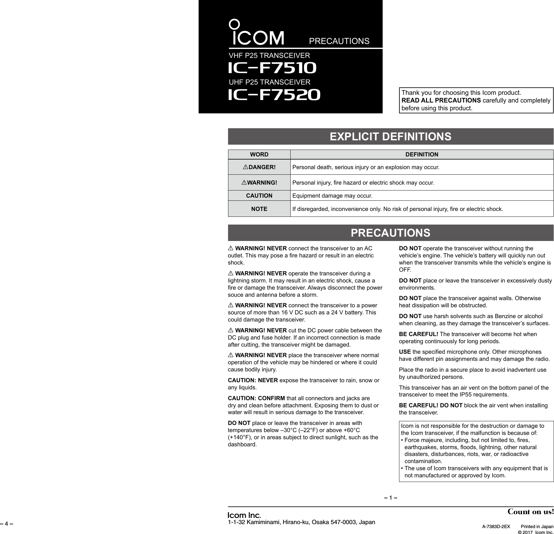
![– 4 –1-1-32 Kamiminami, Hirano-ku, Osaka 547-0003, JapanThank you for choosing this Icom product. READ ALL INSTRUCTIONS carefully and completely before using this product.INSTRUCTIONSVHF P25 TRANSCEIVERIç-F7520UHF P25 TRANSCEIVER Iç-F7510SUPPLIED ACCESSORIESThis instruction sheet includes some functions that are usable only when they are preset by your dealer. The transceiver may have other functions and operations that are not described in this instruction sheet. Ask your dealer for preset function details.IMPORTANTNOTE: Some accessories may not be supplied, or the shape may be different, depending on the transceiver version.A key element in the performance of any communication systems is the antenna. Contact your dealer for information regarding antennas and how to install them.ANTENNAFuses are installed in the supplied DC power cable. If a fuse blows, track down the source of the problem, repair it, and then replace the damaged fuse with a new rated one. Fuse rating: 20A USE only 20 A fusesFUSE REPLACEMENTIf the transceiver becomes dusty or dirty, wipe it clean with a soft, dry cloth.DO NOT use harsh solvents such as Benzine or alcohol, as they may damage the transceiver's surfaces.CLEANINGDC power cableSponges*2Mounting bracketFlat washers Spring washersBracket bolts Mounting screws (M5×12)Self-tapping screws (M5×16)Nuts*2Used for labelling the pro-grammable function keys according to their assinged functions.Used for the optional unit installation.Ask your dealer for details.*1Function name stickers*1Microphone(Self-grounding type)Microphone hanger and screw setA-7383D-1EX Printed in Japan © 2017 Icom Inc.– 1 –Icom, Icom Inc. and the Icom logo are registered trademarks of Icom Incorporated (Japan) in Japan, the United States, the United Kingdom, Germany, France, Spain, Russia, Australia, New Zealand, and/or other countries.The Bluetooth word mark and logos are registered trademarks owned by Bluetooth SIG, Inc. and any use of such marks by Icom inc. is under license. All other products or brands are registered trademarks or trademarks of their respective holders.FUNCTION DISPLAYIcon AreaText AreaKey Display AreaqwNOTE: The screen capture is an example. The displayed position of each icon may differ, depending on the function being used. DIcon AreaIndicatorsq SIGNAL STRENGTH INDICATOR Displays the relative received signal strength.w CLOCK Displays the current time. “AM” or “PM” is displayed beside the time display when the 12 hour display format is selected. “--:--” is displayed instead of the current time when the internal clock is not set.IconsPOWER ICON • “L1” is displayed when the output power is set to low. • “L2” is displayed when the output power is set to mid. • “H” is displayed when the output power is set to high.AUDIBLE ICON Displayed when the channel is in the ‘audible’ (unmute) mode.MESSAGE ICON • Blinks after messages (Message or Status Message) have been received. • Stops blinking when the screen is changed, or any key is pushed, but is displayed if unread messages are still in the Message memory. • Disappears when all messages in the Message memory have been read.BELL ICON Displayed when a matching signal is received, depending on the presetting.SCAN ICON • Displayed when a scan is paused. • Blinks while a scanning.SCAN TARGET CHANNEL ICON • Displayed when the channel is selected as a scan target channel.SCRAMBLER ICON In the Analog mode: • Displayed when the Voice Scrambler function is ON.GPS ICON • Displayed when valid position data is received. • Blinks when searching for satellites or calculating position data.RECORD ICON • Displayed when the Record function is ON. • Blinks while recording audio. “R” is displayed when there is no microSD card free space and you cannot record audio.TALK AROUND ICON Displayed when the Talk Around function is ON.PHONE ICON • Displayed when the transceiver is connected to a telephone network on the selected channel. • Blinks while receiving a phone call.LONE WORKER ICON Displayed when the Lone Worker function is ON.NOISE CANCEL ICON Displayed when the Noise Cancel function is ON. SURVEILLANCE ICON Displayed when the Surveillance function is ON.VOX ICON Displayed when the VOX function is ON.Bluetooth® ICON • Displayed when Bluetooth® is activated. • Lights Blue when a Bluetooth® device is connected. • Does not light when no Bluetooth® device is connected. microSD ICON Displayed when a microSD card is inserted. “R” is displayed when the microSD card has not been formatted.USB ICON Displayed when a USB device is connected. DText AreaDisplays the selected Zone number, Channel number, and Channel name, if set. DKey Display AreaDisplays the assigned function of [P1] and [P2]. Ask your dealer about the assigned Software key function.](https://usermanual.wiki/ICOM-orporated/384700/User-Guide-3406882-Page-1.png)
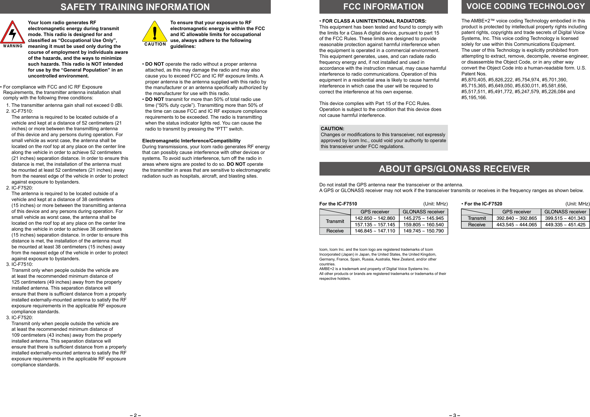
![– 2 – – 3 – DAbout the Status indicator • Lights red while transmitting. • Lights green while receiving a signal, or when the squelch is open.PANEL DESCRIPTION DAbout the Microphone connectorConnect the supplied or optional microphone.NEVER connect non-specifi ed microphones. The pin assignments may be different and may damage the transceiver.Speaker[VOL]Status indicatorMicrophone connectorFunction displaydisplay[OK] [Emer][Emer][Up]/[Down][Right]/[Left][Back][P1] [P2] Power keyREAR PANEL CONNECTIONNOTE: Different functions may have been assigned to the keys by your dealer, except for the Power key. DTurning power ONPush [ ] to turn ON the transceiver. DReceiving and TransmittingReceiving:1. Push [Up] or [Down] to select a channel.2. When receiving a call, rotate [VOL] to adjust the audio output level to a comfortable listening level.Transmitting:1. Wait until the channel is clear to avoid interference.2. While holding down [PTT], speak at your normal voice level. 3. Release [PTT] to receive.BASIC OPERATIONOPTIONS • SP-30, SP-35, SP-35L EXTERNAL SPEAKERS Input impedence: 4 Ω SP-30: Rated input= 20 W, Maximum input = 30 W SP-35/SP35L: Rated input= 5 W, Maximum input = 7 W • HM-220, HM-220T, HM-221, HM-221T HAND MICROPHONES HM-220: Self-grounding heavy duty microphone HM-220T: Self-grounding heavy duty DTMF microphone HM-221: Hand microphone HM-221T: DTMF microphone •SM-29 DESKTOP MICROPHONE •UX-241 GPS ANTENNA Enables you to use the GPS function. •VS-3 Bluetooth® HEADSET The Bluetooth® headset with a [PTT] switch. •About the third party Bluetooth® headsets: Icom has checked the PTT operation with some 3M Peltor headsets such as the WS Headset XP, WS ProTac XP and WS Alert XP. (Compatibility not guaranteed.)IMPORTANT:To maximize the readability of your signal:1. After pushing [PTT], pause briefl y before you start speaking.2. Hold the microphone 5 ~ 10 cm (2 ~ 4 inches) from your mouth, then speak at your normal voice level.Antenna12 VBatteryqerutSolderCrimpNOTE: Use the terminals as shownbelow for the cable connections.wBlackRedyANTENNA CONNECTORConnect to an antenna. Contact your dealer about antenna selection and placement.qwD-Sub 25-pinConnects to an external unit.tGPS ANTENNA CONNECTOR Connect the UX-241 GPS antenna. eIGNITION LEADConnects to an ignition line.Do not put pressure on this lead. Binding to the DC power cable is recommended.uMICROPHONE HANGERFor a self-grounding type:The microphone ON/OFF hook functions can be used without the vehicle’s ground.For a non-self-grounding type:Connect the microphone hanger to the vehicle’s ground for microphone ON/OFF hook functions.rConnects to a 12 V DC battery.Pay attention to polarities. NEVER connect to a 24 V battery. This will damage the transceiver.iiEXTERNAL SPEAKER JACKConnect a 4 ~ 8 Ω external speaker.RR WARNING! NEVER remove the fuse holders from the DC power cable.yUSB (Micro-B) CABLEConnects to a PC.Fuse holdersNon-self-grounding typeSelf-grounding typeUser supplied](https://usermanual.wiki/ICOM-orporated/384700/User-Guide-3406882-Page-2.png)