ICOM orporated 384700 VHF Digital Transceiver User Manual
ICOM Incorporated VHF Digital Transceiver
User Manual
– 4 –1-1-32 Kamiminami, Hirano-ku, Osaka 547-0003, Japan
Thank you for choosing this Icom product.
READ ALL INSTRUCTIONS carefully and completely
before using this product.
INSTRUCTIONS
VHF P25 TRANSCEIVER
Iç-F7520
UHF P25 TRANSCEIVER
Iç-F7510
SUPPLIED ACCESSORIES
This instruction sheet includes some functions that are
usable only when they are preset by your dealer. The
transceiver may have other functions and operations that
are not described in this instruction sheet. Ask your dealer
for preset function details.
IMPORTANT
NOTE: Some accessories may not be supplied, or the
shape may be different, depending on the transceiver
version.
A key element in the performance of any communication
systems is the antenna. Contact your dealer for information
regarding antennas and how to install them.
ANTENNA
Fuses are installed in the supplied DC power cable. If a fuse
blows, track down the source of the problem, repair it, and
then replace the damaged fuse with a new rated one.
Fuse rating: 20A
USE only 20 A fuses
FUSE REPLACEMENT
If the transceiver becomes dusty or dirty, wipe it clean with a
soft, dry cloth.
DO NOT use harsh solvents such as Benzine or
alcohol, as they may damage the transceiver's
surfaces.
CLEANING
DC power cable
Sponges*2
Mounting bracket
Flat washers Spring washers
Bracket bolts Mounting screws
(M5×12)
Self-tapping screws
(M5×16)
Nuts
*2
Used for labelling the pro-
grammable function keys
according to their assinged
functions.
Used for the optional unit
installation.
Ask your dealer for details.
*1
Function name
stickers*1
Microphone
(Self-grounding type)
Microphone hanger
and screw set
A-7383D-1EX Printed in Japan
© 2017 Icom Inc.
– 1 –
Icom, Icom Inc. and the Icom logo are registered trademarks of Icom
Incorporated (Japan) in Japan, the United States, the United Kingdom,
Germany, France, Spain, Russia, Australia, New Zealand, and/or other
countries.
The Bluetooth word mark and logos are registered trademarks owned by
Bluetooth SIG, Inc. and any use of such marks by Icom inc. is under license.
All other products or brands are registered trademarks or trademarks of their
respective holders.
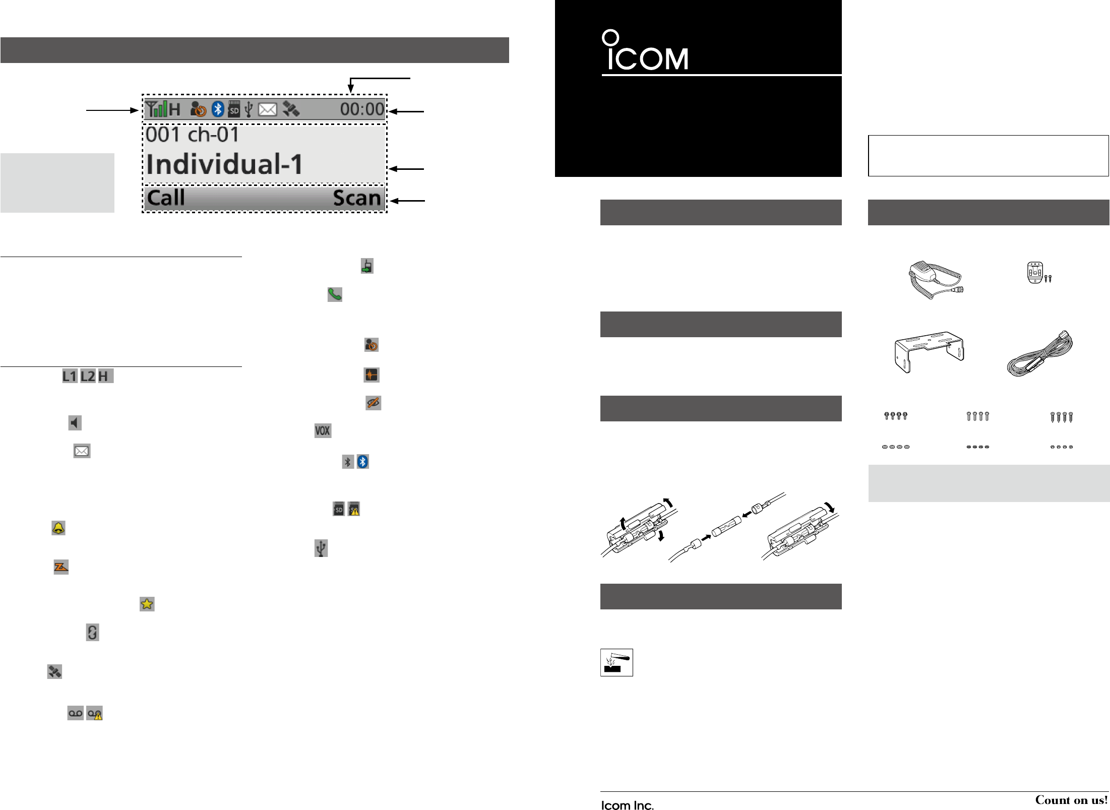
FUNCTION DISPLAY
Icon Area
Text Area
Key Display Area
q
w
NOTE: The screen capture
is an example. The
displayed position of each
icon may differ, depending
on the function being used.
DIcon Area
Indicators
q SIGNAL STRENGTH INDICATOR
Displays the relative received signal strength.
w CLOCK
Displays the current time.
“AM” or “PM” is displayed beside the time display when the 12
hour display format is selected.
“--:--” is displayed instead of the current time when the internal
clock is not set.
Icons
POWER ICON
• “L1” is displayed when the output power is set to low.
• “L2” is displayed when the output power is set to mid.
• “H” is displayed when the output power is set to high.
AUDIBLE ICON
Displayed when the channel is in the ‘audible’ (unmute) mode.
MESSAGE ICON
• Blinks after messages (Message or Status Message) have been
received.
• Stops blinking when the screen is changed, or any key is pushed,
but is displayed if unread messages are still in the Message memory.
• Disappears when all messages in the Message memory have
been read.
BELL ICON
Displayed when a matching signal is received, depending
on the presetting.
SCAN ICON
• Displayed when a scan is paused.
• Blinks while a scanning.
SCAN TARGET CHANNEL ICON
• Displayed when the channel is selected as a scan target channel.
SCRAMBLER ICON
In the Analog mode:
• Displayed when the Voice Scrambler function is ON.
GPS ICON
• Displayed when valid position data is received.
• Blinks when searching for satellites or calculating position data.
RECORD ICON
• Displayed when the Record function is ON.
• Blinks while recording audio.
“R” is displayed when there is no microSD card free space and
you cannot record audio.
TALK AROUND ICON
Displayed when the Talk Around function is ON.
PHONE ICON
• Displayed when the transceiver is connected to a telephone
network on the selected channel.
• Blinks while receiving a phone call.
LONE WORKER ICON
Displayed when the Lone Worker function is ON.
NOISE CANCEL ICON
Displayed when the Noise Cancel function is ON.
SURVEILLANCE ICON
Displayed when the Surveillance function is ON.
VOX ICON
Displayed when the VOX function is ON.
Bluetooth® ICON
• Displayed when Bluetooth® is activated.
• Lights Blue when a Bluetooth® device is connected.
• Does not light when no Bluetooth® device is connected.
microSD ICON
Displayed when a microSD card is inserted.
“R” is displayed when the microSD card has not been formatted.
USB ICON
Displayed when a USB device is connected.
DText Area
Displays the selected Zone number, Channel number, and
Channel name, if set.
DKey Display Area
Displays the assigned function of [P1] and [P2].
Ask your dealer about the assigned Software key function.
– 2 – – 3 –
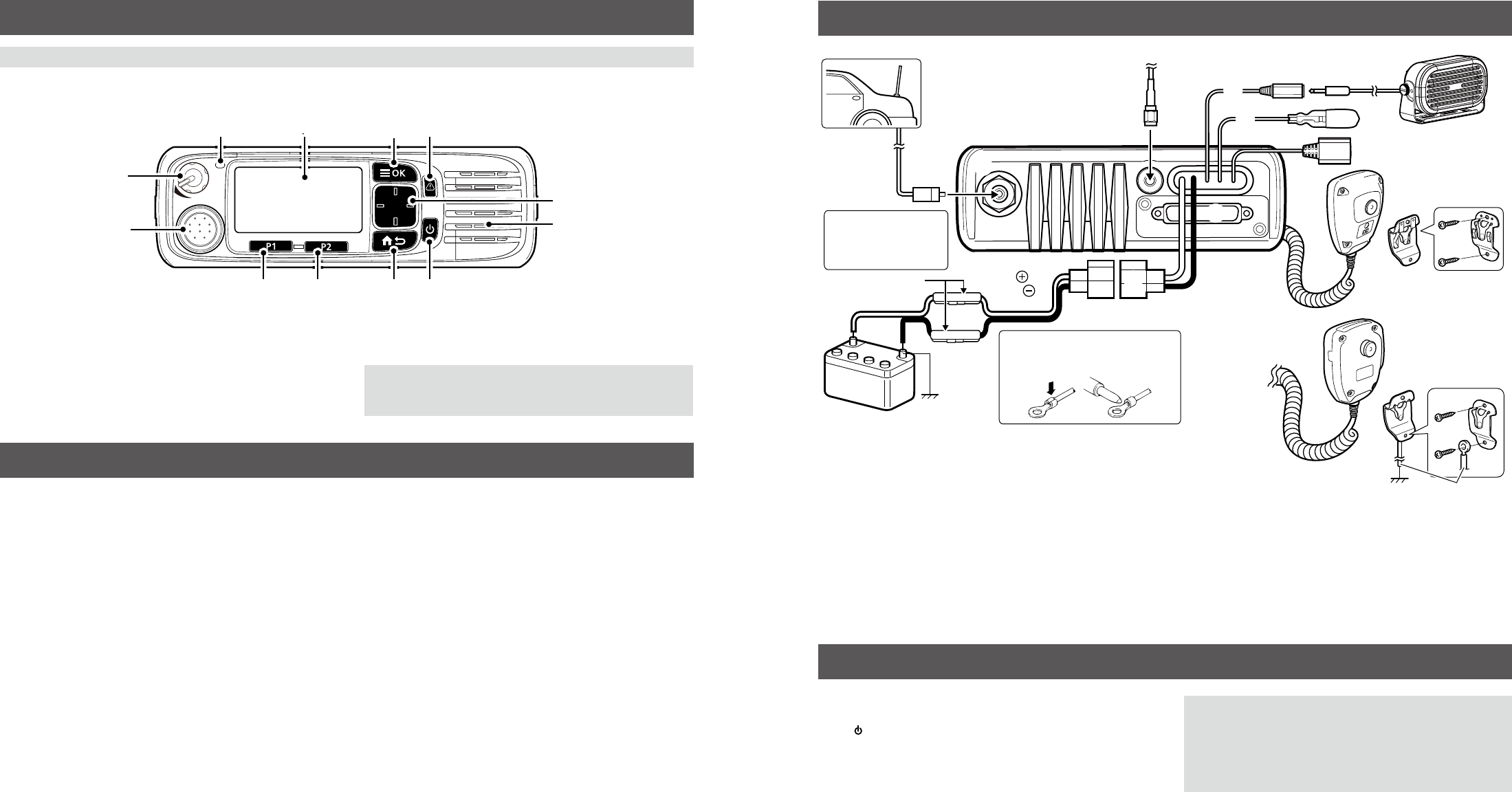
DAbout the Status indicator
• Lights red while transmitting.
• Lights green while receiving a signal, or when the squelch
is open.
PANEL DESCRIPTION
DAbout the Microphone connector
Connect the supplied or optional microphone.
NEVER
connect non-specifi ed microphones. The pin
assignments may be different and may damage the
transceiver.
Speaker
[VOL]
Status
indicator
Microphone
connector
Function
display
display
[OK] [Emer]
[Emer]
[Up]/[Down]
[Right]/[Left]
[Back]
[P1] [P2] Power key
REAR PANEL CONNECTION
NOTE: Different functions may have been assigned to the keys by your dealer, except for the Power key.
DTurning power ON
Push [ ] to turn ON the transceiver.
DReceiving and Transmitting
Receiving:
1. Push [Up] or [Down] to select a channel.
2. When receiving a call, rotate [VOL] to adjust the audio
output level to a comfortable listening level.
Transmitting:
1. Wait until the channel is clear to avoid interference.
2. While holding down [PTT], speak at your normal voice
level.
3. Release [PTT] to receive.
BASIC OPERATION
OPTIONS
• SP-30, SP-35, SP-35L EXTERNAL SPEAKERS
Input impedence: 4 Ω
SP-30: Rated input= 20 W, Maximum input = 30 W
SP-35/SP35L: Rated input= 5 W, Maximum input = 7 W
• HM-220, HM-220T, HM-221, HM-221T HAND MICROPHONES
HM-220: Self-grounding heavy duty microphone
HM-220T: Self-grounding heavy duty DTMF microphone
HM-221: Hand microphone
HM-221T: DTMF microphone
•SM-29 DESKTOP MICROPHONE
•UX-241 GPS ANTENNA
Enables you to use the GPS function.
•VS-3 Bluetooth® HEADSET
The Bluetooth® headset with a [PTT] switch.
•About the third party Bluetooth® headsets:
Icom has checked the PTT operation with some 3M Peltor
headsets such as the WS Headset XP, WS ProTac XP and
WS Alert XP. (Compatibility not guaranteed.)
IMPORTANT:
To maximize the readability of your signal:
1. After pushing [PTT], pause briefl y before you start
speaking.
2. Hold the microphone 5 ~ 10 cm (2 ~ 4 inches) from your
mouth, then speak at your normal voice level.
Antenna
12 V
Battery
q
e
r
u
t
Solder
Crimp
NOTE: Use the terminals as shown
below for the cable connections.
w
Black
Red
y
ANTENNA CONNECTOR
Connect to an antenna. Contact
your dealer about antenna selection
and placement.
q
w
D-Sub 25-pin
Connects to an external unit.
t
GPS ANTENNA CONNECTOR
Connect the UX-241 GPS antenna.
e
IGNITION LEAD
Connects to an ignition line.
Do not put pressure on this
lead. Binding to the DC power
cable is recommended.
uMICROPHONE HANGER
For a self-grounding type:
The microphone ON/OFF hook functions
can be used without the vehicle’s ground.
For a non-self-grounding type:
Connect the microphone hanger to the
vehicle’s ground for microphone ON/OFF
hook functions.
r
Connects to a 12 V DC battery.
Pay attention to polarities. NEVER connect
to a 24 V battery.
This will damage the transceiver.
i
i
EXTERNAL SPEAKER JACK
Connect a 4 ~ 8 Ω external speaker.
R
R WARNING! NEVER
remove the fuse
holders from the DC
power cable.
yUSB (Micro-B) CABLE
Connects to a PC.
Fuse holders
Non-self-grounding type
Self-grounding type
User supplied
– 4 –
– 1 –
Thank you for choosing this Icom product.
READ ALL PRECAUTIONS carefully and completely
before using this product.
1-1-32 Kamiminami, Hirano-ku, Osaka 547-0003, Japan A-7383D-2EX Printed in Japan
© 2017 Icom Inc.
PRECAUTIONS
VHF P25 TRANSCEIVER
Iç-F7520
UHF P25 TRANSCEIVER
Iç-F7510
WORD DEFINITION
RDANGER! Personal death, serious injury or an explosion may occur.
RWARNING! Personal injury, re hazard or electric shock may occur.
CAUTION Equipment damage may occur.
NOTE If disregarded, inconvenience only. No risk of personal injury, re or electric shock.
RWARNING! NEVER connect the transceiver to an AC
outlet. This may pose a re hazard or result in an electric
shock.
RWARNING! NEVER operate the transceiver during a
lightning storm. It may result in an electric shock, cause a
re or damage the transceiver. Always disconnect the power
souce and antenna before a storm.
RWARNING! NEVER connect the transceiver to a power
source of more than 16 V DC such as a 24 V battery. This
could damage the transceiver.
RWARNING! NEVER cut the DC power cable between the
DC plug and fuse holder. If an incorrect connection is made
after cutting, the transceiver might be damaged.
RWARNING! NEVER place the transceiver where normal
operation of the vehicle may be hindered or where it could
cause bodily injury.
CAUTION: NEVER expose the transceiver to rain, snow or
any liquids.
CAUTION: CONFIRM that all connectors and jacks are
dry and clean before attachment. Exposing them to dust or
water will result in serious damage to the transceiver.
DO NOT place or leave the transceiver in areas with
temperatures below –30°C (–22°F) or above +60°C
(+140°F), or in areas subject to direct sunlight, such as the
dashboard.
DO NOT operate the transceiver without running the
vehicle’s engine. The vehicle’s battery will quickly run out
when the transceiver transmits while the vehicle’s engine is
OFF.
DO NOT place or leave the transceiver in excessively dusty
environments.
DO NOT place the transceiver against walls. Otherwise
heat dissipation will be obstructed.
DO NOT use harsh solvents such as Benzine or alcohol
when cleaning, as they damage the transceiver’s surfaces.
BE CAREFUL! The transceiver will become hot when
operating continuously for long periods.
USE the specied microphone only. Other microphones
have different pin assignments and may damage the radio.
Place the radio in a secure place to avoid inadvertent use
by unauthorized persons.
This transceiver has an air vent on the bottom panel of the
transceiver to meet the IP55 requirements.
BE CAREFUL! DO NOT block the air vent when installing
the transceiver.
EXPLICIT DEFINITIONS
Icom is not responsible for the destruction or damage to
the Icom transceiver, if the malfunction is because of:
• Force majeure, including, but not limited to, res,
earthquakes, storms, oods, lightning, other natural
disasters, disturbances, riots, war, or radioactive
contamination.
• The use of Icom transceivers with any equipment that is
not manufactured or approved by Icom.
PRECAUTIONS
– 2 – – 3 –
WARNING
Your Icom radio generates RF
electromagnetic energy during transmit
mode. This radio is designed for and
classied as “Occupational Use Only”,
meaning it must be used only during the
course of employment by individuals aware
of the hazards, and the ways to minimize
such hazards. This radio is NOT intended
for use by the “General Population” in an
uncontrolled environment.
• For compliance with FCC and IC RF Exposure
Requirements, the transmitter antenna installation shall
comply with the following three conditions:
1. The transmitter antenna gain shall not exceed 0 dBi.
2. IC-F7510:
The antenna is required to be located outside of a
vehicle and kept at a distance of 52 centimeters (21
inches) or more between the transmitting antenna
of this device and any persons during operation. For
small vehicle as worst case, the antenna shall be
located on the roof top at any place on the center line
along the vehicle in order to achieve 52 centimeters
(21 inches) separation distance. In order to ensure this
distance is met, the installation of the antenna must
be mounted at least 52 centimeters (21 inches) away
from the nearest edge of the vehicle in order to protect
against exposure to bystanders.
2. IC-F7520:
The antenna is required to be located outside of a
vehicle and kept at a distance of 38 centimeters
(15 inches) or more between the transmitting antenna
of this device and any persons during operation. For
small vehicle as worst case, the antenna shall be
located on the roof top at any place on the center line
along the vehicle in order to achieve 38 centimeters
(15 inches) separation distance. In order to ensure this
distance is met, the installation of the antenna must
be mounted at least 38 centimeters (15 inches) away
from the nearest edge of the vehicle in order to protect
against exposure to bystanders.
3. IC-F7510:
Transmit only when people outside the vehicle are
at least the recommended minimum distance of
125 centimeters (49 inches) away from the properly
installed antenna. This separation distance will
ensure that there is sufcient distance from a properly
installed externally-mounted antenna to satisfy the RF
exposure requirements in the applicable RF exposure
compliance standards.
3. IC-F7520:
Transmit only when people outside the vehicle are
at least the recommended minimum distance of
109 centimeters (43 inches) away from the properly
installed antenna. This separation distance will
ensure that there is sufcient distance from a properly
installed externally-mounted antenna to satisfy the RF
exposure requirements in the applicable RF exposure
compliance standards.
CAUTION
To ensure that your exposure to RF
electromagnetic energy is within the FCC
and IC allowable limits for occupational
use, always adhere to the following
guidelines:
• DO NOT operate the radio without a proper antenna
attached, as this may damage the radio and may also
cause you to exceed FCC and IC RF exposure limits. A
proper antenna is the antenna supplied with this radio by
the manufacturer or an antenna specically authorized by
the manufacturer for use with this radio.
• DO NOT transmit for more than 50% of total radio use
time (“50% duty cycle”). Transmitting more than 50% of
the time can cause FCC and IC RF exposure compliance
requirements to be exceeded. The radio is transmitting
when the status indicator lights red. You can cause the
radio to transmit by pressing the “PTT” switch.
Electromagnetic Interference/Compatibility
During transmissions, your Icom radio generates RF energy
that can possibly cause interference with other devices or
systems. To avoid such interference, turn off the radio in
areas where signs are posted to do so. DO NOT operate
the transmitter in areas that are sensitive to electromagnetic
radiation such as hospitals, aircraft, and blasting sites.
SAFETY TRAINING INFORMATION
•FOR CLASS A UNINTENTIONAL RADIATORS:
This equipment has been tested and found to comply with
the limits for a Class A digital device, pursuant to part 15
of the FCC Rules. These limits are designed to provide
reasonable protection against harmful interference when
the equipment is operated in a commercial environment.
This equipment generates, uses, and can radiate radio
frequency energy and, if not installed and used in
accordance with the instruction manual, may cause harmful
interference to radio communications. Operation of this
equipment in a residential area is likely to cause harmful
interference in which case the user will be required to
correct the interference at his own expense.
This device complies with Part 15 of the FCC Rules.
Operation is subject to the condition that this device does
not cause harmful interference.
CAUTION:
Changes or modications to this transceiver, not expressly
approved by Icom Inc., could void your authority to operate
this transceiver under FCC regulations.
FCC INFORMATION
The AMBE+2™ voice coding Technology embodied in this
product is protected by intellectual property rights including
patent rights, copyrights and trade secrets of Digital Voice
Systems, Inc. This voice coding Technology is licensed
solely for use within this Communications Equipment.
The user of this Technology is explicitly prohibited from
attempting to extract, remove, decompile, reverse engineer,
or disassemble the Object Code, or in any other way
convert the Object Code into a human-readable form. U.S.
Patent Nos.
#5,870,405, #5,826,222, #5,754,974, #5,701,390,
#5,715,365, #5,649,050, #5,630,011, #5,581,656,
#5,517,511, #5,491,772, #5,247,579, #5,226,084 and
#5,195,166.
VOICE CODING TECHNOLOGY
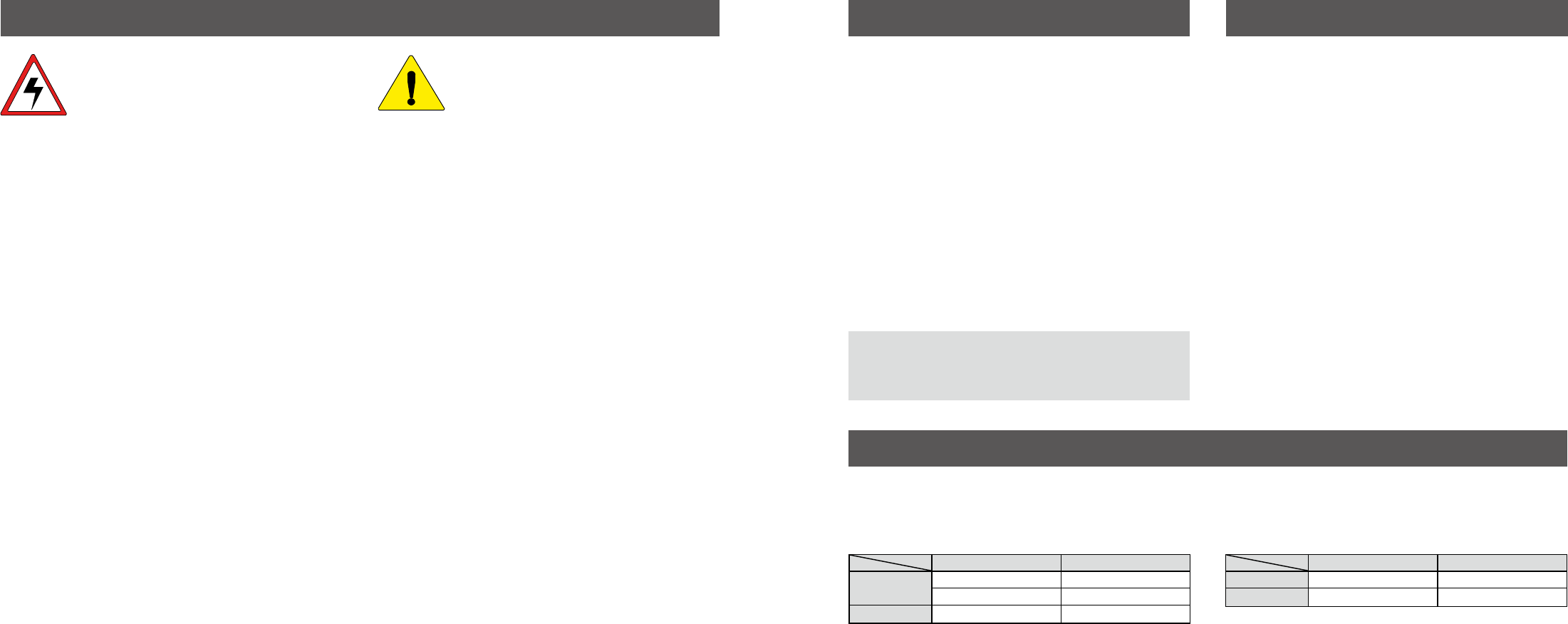
ABOUT GPS/GLONASS RECEIVER
Do not install the GPS antenna near the transceiver or the antenna.
A GPS or GLONASS receiver may not work if the transceiver transmits or receives in the frequency ranges as shown below.
For the IC-F7510 (Unit: MHz)
GPS receiver GLONASS receiver
Transmit 142.850 ~ 142.860 145.275 ~ 145.945
157.135 ~ 157.145 159.805 ~ 160.540
Receive 146.845 ~ 147.110 149.745 ~ 150.790
•For the IC-F7520 (Unit: MHz)
GPS receiver GLONASS receiver
Transmit 392.840 ~ 392.865 399.515 ~ 401.343
Receive 443.545 ~ 444.065 449.335 ~ 451.425
Icom, Icom Inc. and the Icom logo are registered trademarks of Icom
Incorporated (Japan) in Japan, the United States, the United Kingdom,
Germany, France, Spain, Russia, Australia, New Zealand, and/or other
countries.
AMBE+2 is a trademark and property of Digital Voice Systems Inc.
All other products or brands are registered trademarks or trademarks of their
respective holders.