ICOM orporated 386400 IC-7610 User Manual IC 7610 ENG Basic 0 Book indb
ICOM Incorporated IC-7610 IC 7610 ENG Basic 0 Book indb
UserManual.wiki
>
ICOM orporated
>
386400 User Manual
User Manual
Navigation menu
Upload a User Manual
Namespaces
Wiki Guide
HTML
PDF
Info
Views
User Manual
Discussion / Help
Navigation
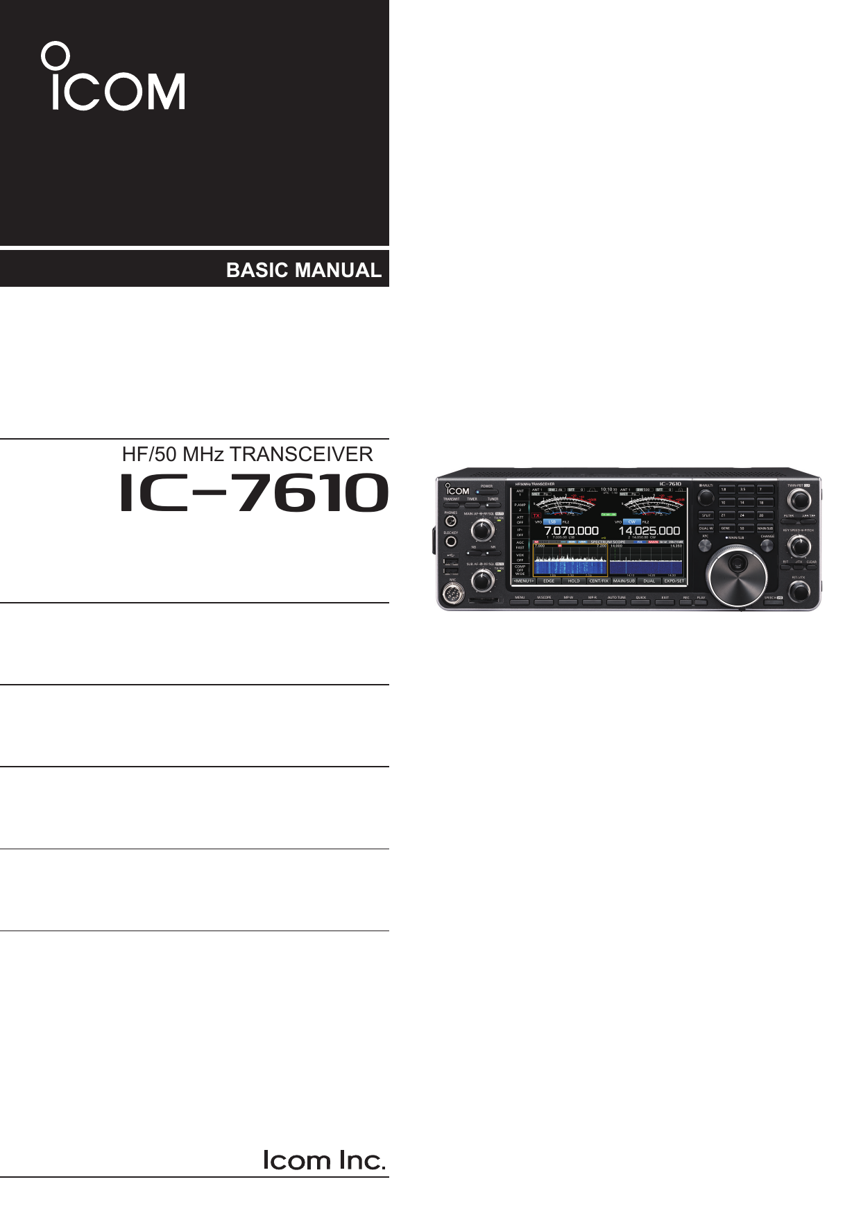
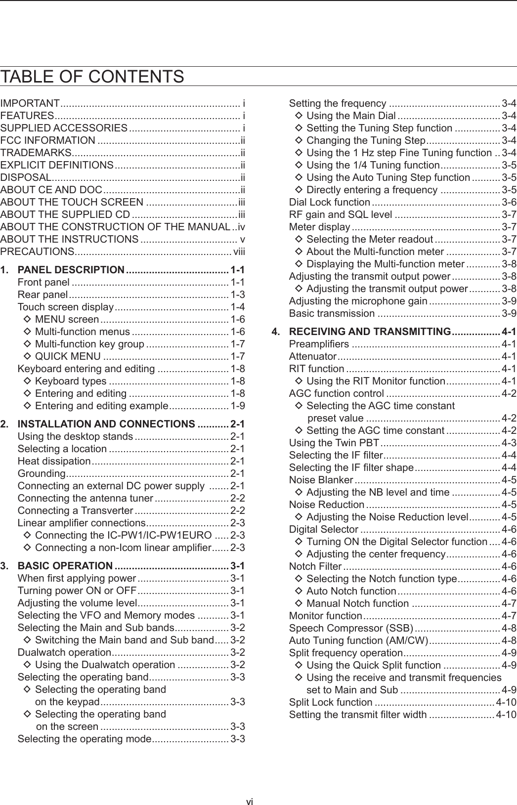
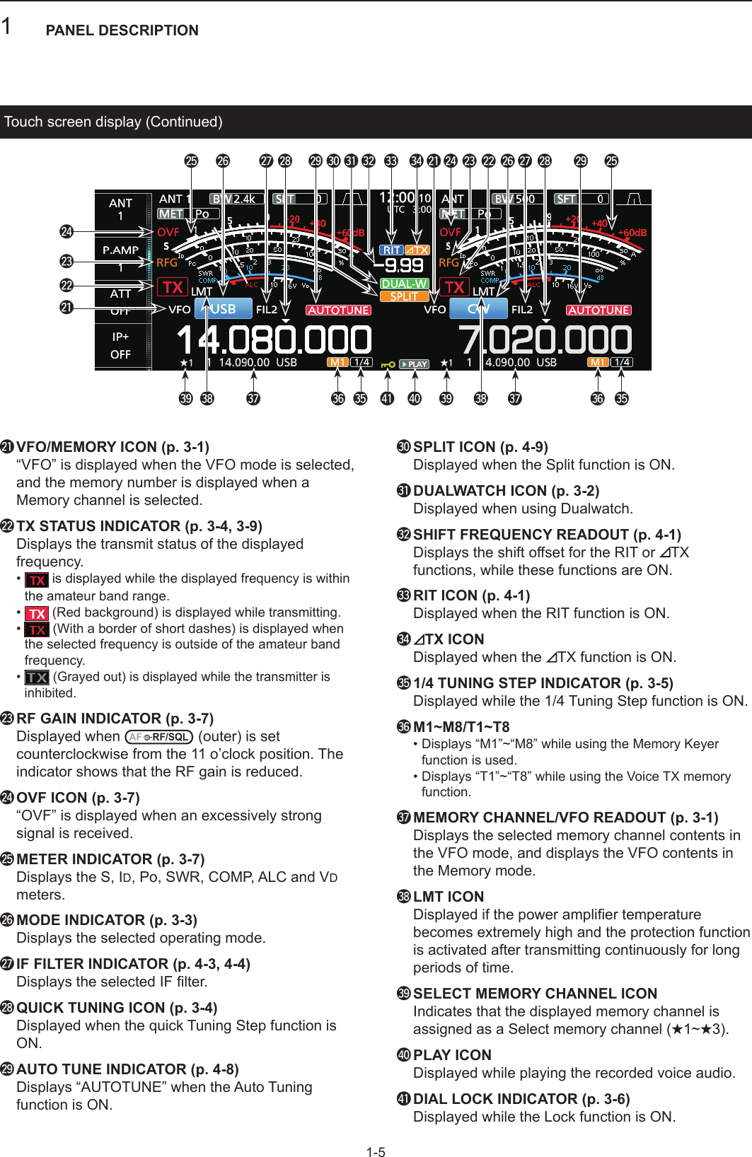
![iii DTouch operationIn the Full manual or Basic manual, the touch operation is described as shown below.TouchIf the display is touched briey, one short beep sounds.Touch for 1 secondIf the display is touched for 1 second, one short and one long beep sound. DTouch screen precautions • The touch screen may not properly work when the LCD protection lm or sheet is attached. • Touching the screen with your nger nails, sharp topped object and so on, or touching the screen hard may damage it. • Tablet PC’s operations such as ick, pinch in and pinch out cannot be performed on this touch screen. DTouch screen maintenance • If the touch screen becomes dusty or dirty, wipe it clean with a soft, dry cloth. • When you wipe the touch screen, be careful not to push it too hard or scratch it with your nger nails. Otherwise you may damage the screen.The following items are included on the CD. •Basic manual (English) Instructions for basic operations, the same as this manual. •Advanced manual (English) Instructions for advanced operations in English. • Basic manual (Multi-language) Instructions for basic operations in multiple languages. •Schematic diagram Includes the schematic and block diagrams. •HAM radio Terms (English) A glossary of HAM radio terms in English. •Adobe® Reader® Installer Installer for Adobe® Reader®.A PC with the following Operating System is required. • Microsoft® Windows® 10 • Microsoft® Windows® 8.1 • Microsoft® Windows® 7To read the manuals or Schematic diagram, Adobe® Acrobat® Reader® is required. If you have not installed it, please install the Adobe Acrobat Reader on the CD or download it from Adobe Systems Incorporated’s website.Starting the CD1. Insert the CD into the CD drive.2. Double click “Menu.exe” on the CD. • Depending on the PC setting, the menu screen shown below is automatically displayed.3. Click the desired button to open the file.L To close the Menu screen, click [Quit].ABOUT THE TOUCH SCREENABOUT THE SUPPLIED CDL Different types of menu screen may be displayed, depending on the transceiver version.Closes the Menu screenInstalls Adobe® Acrobat® Reader®Opens the multi-language Basic manual Opens the Schematic diagram Opens the GlossaryOpens the English Basic manual (this manual)Opens the English Advanced manual](https://usermanual.wiki/ICOM-orporated/386400/User-Guide-3628432-Page-4.png)
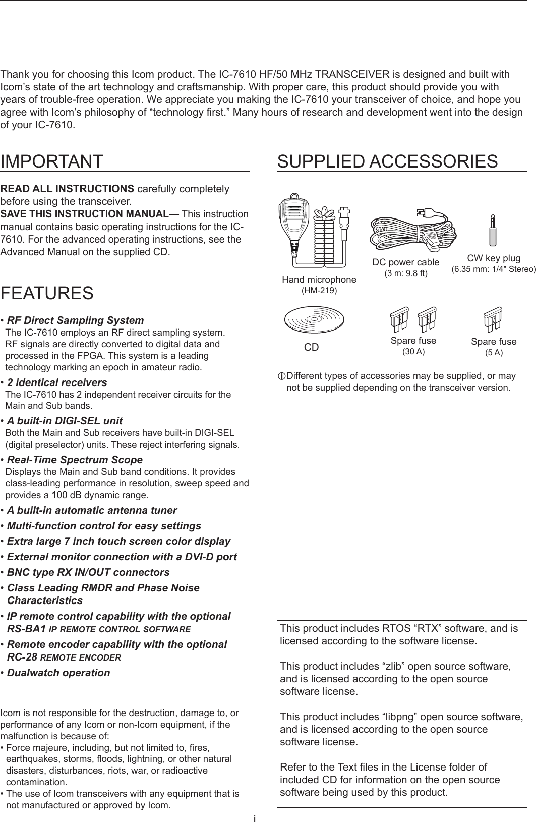
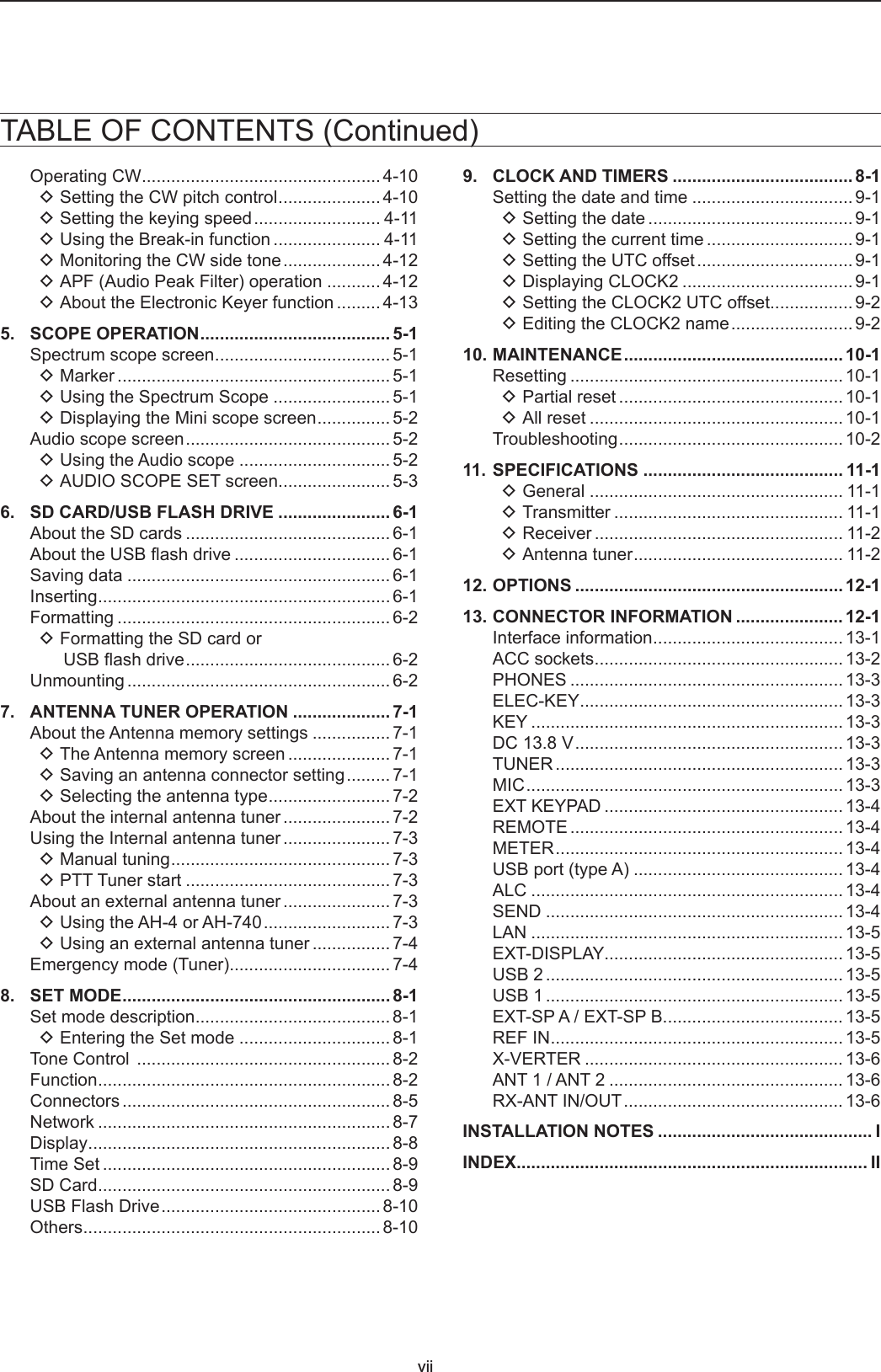
![vABOUT THE INSTRUCTIONSInstruction exampleMENU » SET > Time Set > Date/TimeDetailed instruction1. Push MENU. • Opens the MENU screen.2. Touch [SET]. • Opens the SET screen.3. Touch “Time Set.” • Opens the TIME SET screen.4. Touch “Date/Time.” • Opens the DATE/TIME screen.5. Touch “Date.” • Opens the date editing screen.6. Touch [+] and [-] to set the date.The Basic and Advanced manuals are described in the following manner.“ ” (Quotation marks):Used to indicate icons, setting items, and screen titles displayed on the screen. The screen titles are also indicated in uppercase letters. (Example: FUNCTION screen)[ ] (brackets): Used to indicate keys.Routes in the set modes and setting screensRoutes in the set mode, setting screen and the setting items are described in the following manner.7. Touch [SET] to set the date.LTouch to cancel. • Returns to the previous screen. DSetting the current date1. Open the DATE/TIME screen.MENU » SET > Time Set > Date/Time2. Touch “Date/Time.”3. Touch “Date.” • Opens the date editing screen.MENU](https://usermanual.wiki/ICOM-orporated/386400/User-Guide-3628432-Page-6.png)
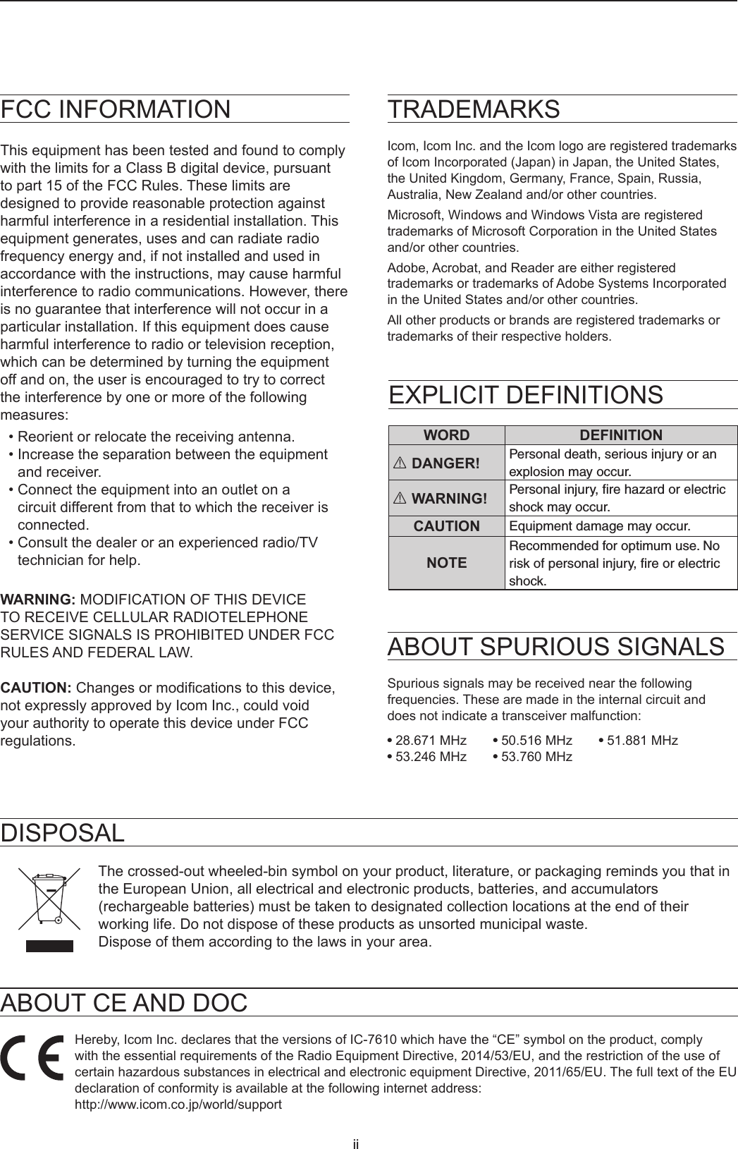
![viiiPRECAUTIONSR DANGER HIGH RF VOLTAGE! NEVER touch an antenna or antenna connector while transmitting. This could cause an electrical shock or burn.R DANGER! NEVER operate the transceiver near unshielded electrical blasting caps or in an explosive atmosphere. This could cause an explosion and death.R WARNING RF EXPOSURE! This device emits Radio Frequency (RF) energy. Extreme caution should be observed when operating this device. If you have any questions regarding RF exposure and safety standards please refer to the Federal Communications Commission Ofce of Engineering and Technology’s report on Evaluating Compliance with FCC Guidelines for Human Radio Frequency Electromagnetic Fields (OET Bulletin 65).R WARNING! NEVER operate the transceiver with a headset or other audio accessories at high volume levels. If you experience a ringing in your ears, reduce the volume or discontinue use.R WARNING! NEVER apply AC power to the [DC13.8V] socket on the transceiver rear panel. This could cause a re or damage the transceiver.R WARNING! NEVER apply more than 16 V DC to the [DC13.8V] socket on the transceiver rear panel. This could cause a re or damage the transceiver.R WARNING! NEVER reverse the DC power cable polarity. This could cause a re or damage the transceiver.R WARNING! NEVER remove the fuse holder on the DC power cable. Excessive current caused by a short could cause a re or damage the transceiver.R WARNING! NEVER let metal, wire or other objects contact the inside of the transceiver, or make incorrect contact with connectors on the rear panel. This could cause an electric shock or damage the transceiver.R WARNING! NEVER operate or touch the transceiver with wet hands. This could cause an electric shock or damage to the transceiver.R WARNING! NEVER operate the equipment if you notice an abnormal odor, sound or smoke. Immediately turn OFF the power and/or remove the DC power cable. Contact your Icom dealer or distributor for advice.R WARNING! NEVER put the transceiver on an unstable place where the transceiver may suddenly move or fall. This could cause an injury or damage the transceiver.R WARNING! NEVER operate the transceiver during a lightning storm. It may result in an electric shock, cause a re or damage the transceiver. Always disconnect the power source and antenna before a storm.CAUTION: DO NOT expose the transceiver to rain, snow or any liquids. They could damage the transceiver.CAUTION: DO NOT change the internal settings of the transceiver. This may reduce transceiver performance and/or damage the transceiver. The transceiver warranty does not cover any problems caused by unauthorized internal adjustments.CAUTION: DO NOT install the equipment in a place without adequate ventilation, or block any cooling vents on the top, rear, sides or bottom of the transceiver or the cooling fan. Heat dissipation may be reduced and damage the transceiver.CAUTION: DO NOT use harsh solvents such as benzine or alcohol when cleaning. This could damage the equipment surfaces. If the surface becomes dusty or dirty, wipe it clean with a soft, dry cloth.CAUTION: DO NOT place or leave the transceiver in areas with temperatures below 0°C (32°F) or above 50°C (122°F).CAUTION: DO NOT place the transceiver in excessively dusty environments, or in direct sunlight. This could damage the transceiver.CAUTION: DO NOT set the transceiver’s RF output power to more than a connected linear amplier’s maximum input level. Otherwise, the linear amplier will be damaged.CAUTION: DO NOT use non-Icom microphones. Other microphones have different pin assignments and may damage the transceiver.BE CAREFUL! The transceiver will become hot when operating the transceiver continuously for long periods of time.NEVER leave the transceiver in an insecure place to avoid use by unauthorized persons.Turn OFF the transceiver’s power and disconnect the DC power cable when you will not use the transceiver for long period of time.The LCD display may have cosmetic imperfections that appear as small dark or light spots. This is not a malfunction or defect, but a normal characteristic of LCD displays.](https://usermanual.wiki/ICOM-orporated/386400/User-Guide-3628432-Page-9.png)
![1PANEL DESCRIPTION1-1Front panelq POWER KEY POWER (p. 3-1) Turns the transceiver ON or OFF.w TRANSMIT KEY TRANSMIT (p. 3-9) Toggles between transmit and receive.e TIMER KEY TIMER Turns the Sleep Timer or Daily Timer function ON or OFF.!3 !4 !5 !6 !7 !8 !9 @0 @1rtyu!2o!0wqe!1oir HEADPHONE JACK [PHONES] (p. 13-3) Connects to standard stereo headphones.t ELECTRONIC KEYER JACK [ELEC-KEY] (p. 13-3) Connects to a paddle to use the internal electronic keyer for the CW operations.y USB PORT [USB A] (p. 13-4) InsertaUSBashdrive,USBAtypekeyboard,RC-28 remote encoder,mouseorhub.u MICROPHONE CONNECTOR [MIC] (p. 13-3) Connects to the supplied or an optional microphone.i SD CARD SLOT [SD CARD] (p. 6-1) AcceptsanSDcard.Theindicatornexttotheslotlights blue when inserted.o VOLUME CONTROL AF RF/SQL (p. 3-1)LTheuppercontrolisfortheMainband,andthelower control is for the Sub band. • Push to turn the Mute function ON or OFF. -TheTX/RXindicatorlightsorangewhenturnedON. •Adjuststheaudiooutputlevel. RF GAIN/SQUELCH CONTROL AF RF/SQL (p. 3-7) AdjuststheRFgainandsquelchthresholdlevels.!0 NOISE REDUCTION KEY NR (p. 6-5) TurnstheNoiseReductionfunctionONorOFF.!1 NOISE BLANKER KEY NB (p. 6-5) Turns the Noise Blanker ON or OFF.!2 ANTENNA TUNER KEY TUNER (p. 7-3) TurnstheantennatunerONorOFF,oractivatesthe tuner.The TX/RX indicator • Lights green while receiving. • Lights red while transmitting.!3 MENU KEY MENU (p. 8-1) Displays the MENU screen.!4 MINI SCOPE KEY M.SCOPE (p. 5-2) Displays the Mini Scope or Spectrum Scope.!5 MEMO PAD WRITE KEY MP-W Saves the displayed contents into the Memo Pad.!6 MEMO PAD READ KEY MP-R SequentiallycallsupthecontentsintheMemoPad.!7 AUTO TUNE KEY AUTO TUNE (p. 4-8) Automaticallytunestheoperatingfrequencytoareceived CW signal.!8 QUICK KEY QUICK (p. 1-7) Displays the QUICK MENU.](https://usermanual.wiki/ICOM-orporated/386400/User-Guide-3628432-Page-10.png)
![1PANEL DESCRIPTION1-3q DC POWER SOCKET [DC 13.8 V] Connects to 13.8 V DC through the DC power cable.w TUNER CONTROL SOCKET [TUNER] Acceptsthecontrolcablefromanoptional AH-4 orAH-740automatic antenna tuner.e COOLING FAN CoolsthePAunitwhennecessary.r GROUND TERMINAL [GND] Connectstogroundtopreventelectricalshocks,TVI,BCIandotherproblems.t ANTENNA CONNECTOR [ANT1]/[ANT2] Connectstoa50Ωantenna.IfyouusetheAH-4orAH-740,youmustconnecttheantennato[ANT1].y ALC INPUT JACK [ALC] ConnectstotheALCoutputjackofanon-Icomlinearamplier.u SEND CONTROL JACK [SEND] Connectstocontroltransmitwithnon-Icomexternalunits.i EXTERNAL SPEAKER JACK A/B [EXT-SP] Acceptsa4~8Ωexternalspeaker.o USB PORT [USB 1] (Type B) Connects to a PC for remote control operations.!0 USB PORT [USB 2] (Type B) For digital data input or output.!1 EXTERNAL DISPLAY CONNECTOR [EXT-DISPLAY] Connectstoanexternaldisplaymonitor.!2 ETHERNET CONNECTOR [LAN] ConnectstoaPCnetworkthroughaLAN.!3 TRANSVERTER CONNECTOR [X-VERTER] Connectstoanexternaltransverterforinput/output.!4 REFERENCE SIGNAL INPUT [REF IN] Inputfora10MHzreferencesignalthroughtheBNC connector.!5 RECEIVE ANTENA [RX ANT–IN]/[RX ANT–OUT] Connectstoanexternalunit,suchaspreamplierorRFlter,usingBNCconnectors. • This is located between the transmit/receive switching circuitandreceiver’sRFstage.!6 CI-V REMOTE CONTROL JACK [REMOTE] Connects to a PC or other transceiver for remote control.!7 METER JACK [METER] Outputsreceivedsignalstrength,transmitoutputpower,VSWR,ALC,speechcompression,Vd or Id levelsforanexternalmeter.!8 EXTERNAL KEYPAD JACK [EXT KEYPAD] (p. 13- 4) Connectstoanexternalkeypadfordirectvoicememory,memorykeyer,RTTYmemoryorPSKmemory transmission.!9 STRAIGHT KEY JACK [KEY] Connectstoastraightkey,paddle,oranexternalelectronic keyer with 6.35 mm (¼ in) stereo plug.@0 ACC SOCKET [ACC1]/[ACC2] Connectstodevicestocontrolanexternalunitortocontrol the transceiver.Rear panelq ew r!5!4 !3 !2 !1 o iy!6 !7 !8!5 !9tu!0](https://usermanual.wiki/ICOM-orporated/386400/User-Guide-3628432-Page-12.png)
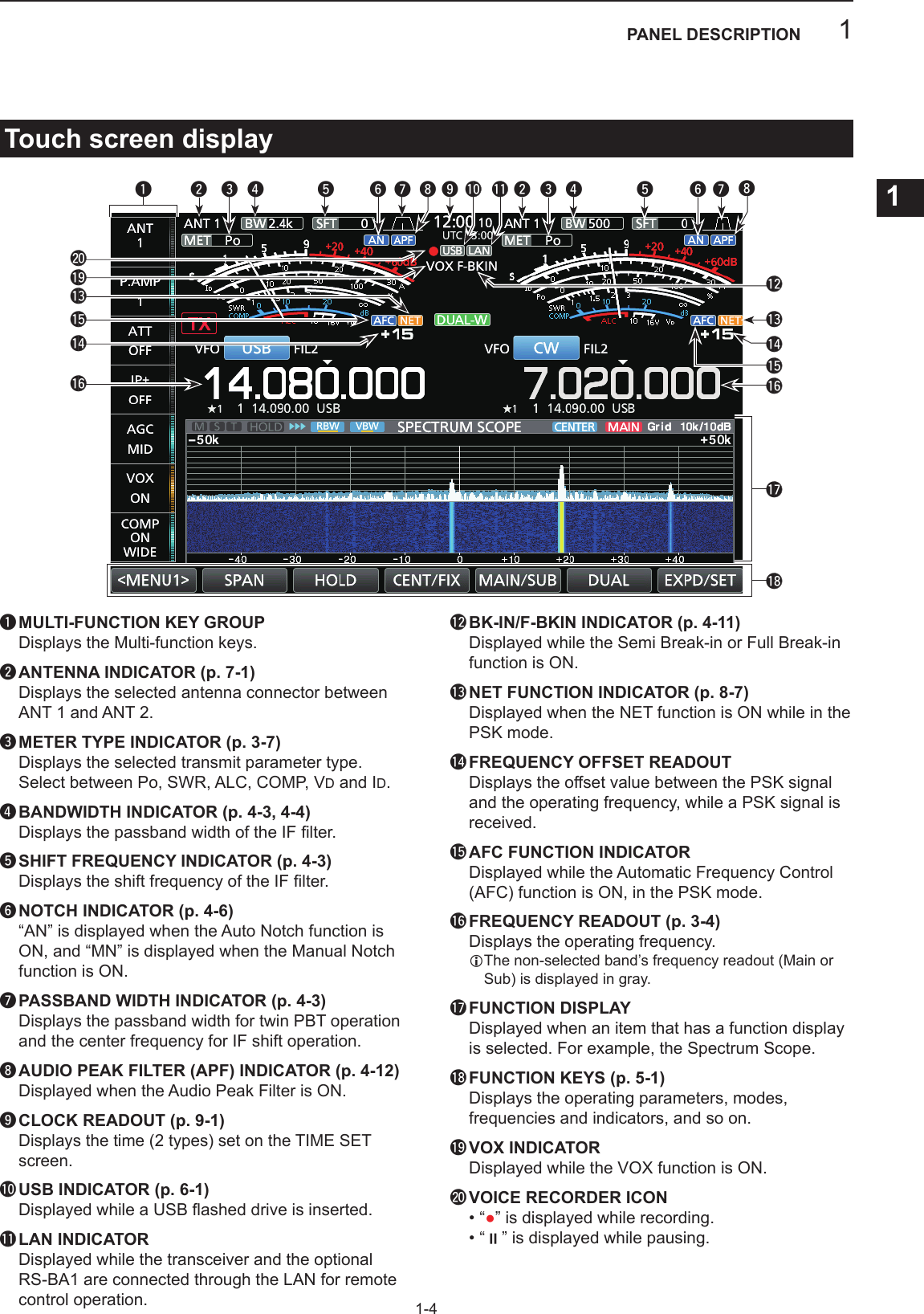
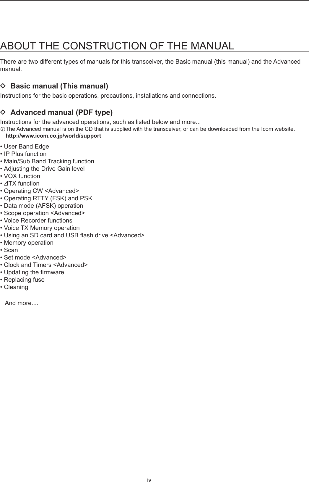
![1PANEL DESCRIPTION1-9Keypad entering and editing (Continued) DEntering and editing exampleEntering“DXspot1”intheMemorychannel21. DisplaytheMEMORYscreen.MENU » MEMORY2. Touch the memory channel 2 for 1 second. • TheMEMORYMENUscreenisdisplayed.3. Touch“EditName.” • TheMEMORYNAMEscreenisdisplayed.4. Touch[],andthentouch[D].LTouching[]changesbetweenuppercaseandlowercase letter.5. Touch[]again,andthentouch[X].6. Touch[SPACE]toenteraspace.7. Touch[s],[p],[o],andthen[t].8. Touch[SPACE]toenteraspace.9. Touch[ab]. • TheCHARACTERTYPEscreenisdisplayed.10. Touch[12].11. Touch[1].12. Touch[ENT]tosavetheentry. • Returnstothepreviousscreen.YoucanalsodisplaytheMEMORYMENU screen by touching this key.](https://usermanual.wiki/ICOM-orporated/386400/User-Guide-3628432-Page-18.png)