ICOM orporated 386400 IC-7610 User Manual IC 7610 ENG Basic 0 Book indb
ICOM Incorporated IC-7610 IC 7610 ENG Basic 0 Book indb
User Manual
BASIC MANUAL
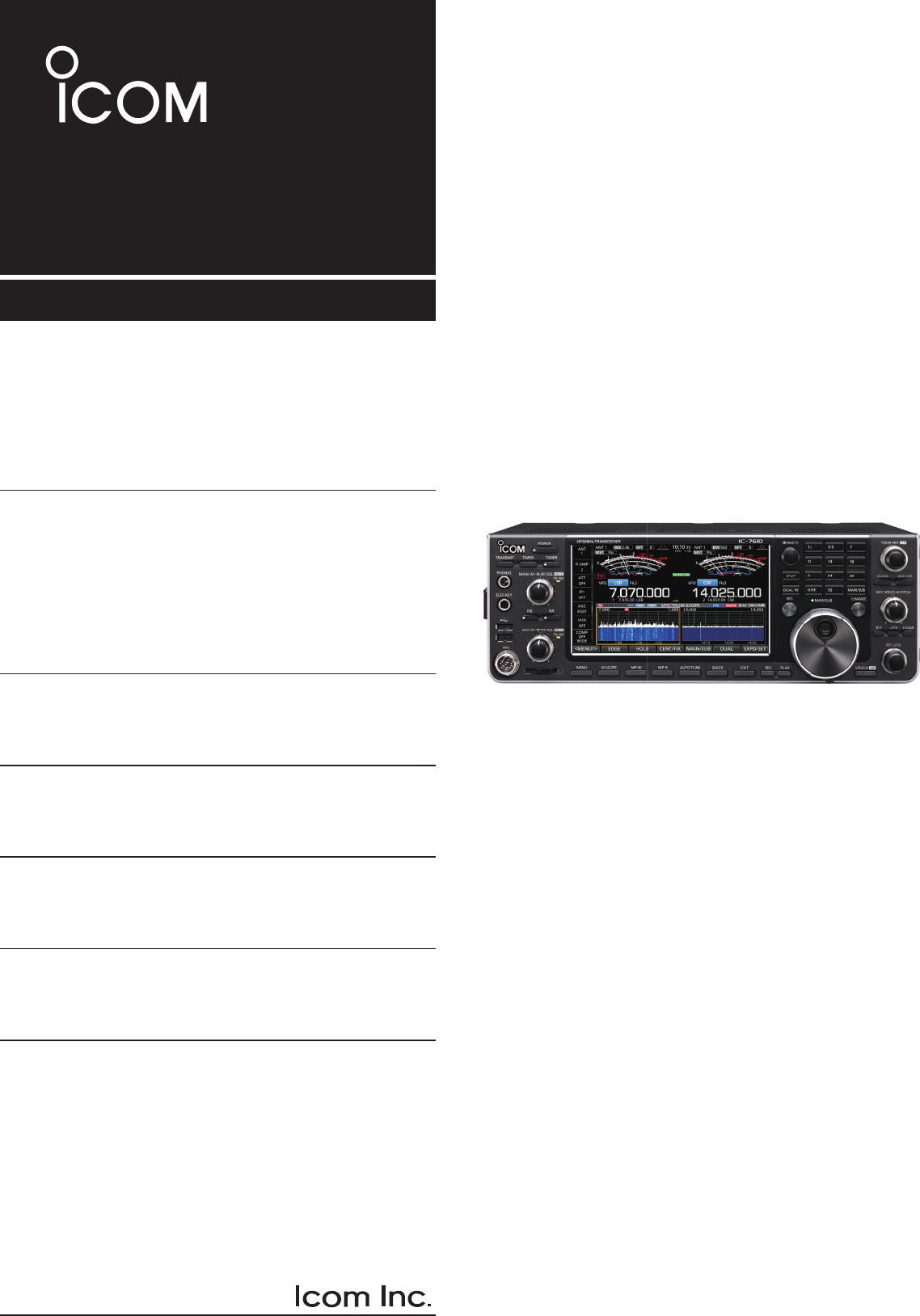
i7610
HF/50 MHz TRANSCEIVER
i
Thank you for choosing this Icom product. The IC-7610 HF/50 MHz TRANSCEIVER is designed and built with
Icom’s state of the art technology and craftsmanship. With proper care, this product should provide you with
years of trouble-free operation. We appreciate you making the IC-7610 your transceiver of choice, and hope you
agree with Icom’s philosophy of “technology rst.” Many hours of research and development went into the design
of your IC-7610.
FEATURES
•RF Direct Sampling System
The IC-7610 employs an RF direct sampling system.
RF signals are directly converted to digital data and
processed in the FPGA. This system is a leading
technology marking an epoch in amateur radio.
•2 identical receivers
The IC-7610 has 2 independent receiver circuits for the
Main and Sub bands.
•A built-in DIGI-SEL unit
Both the Main and Sub receivers have built-in DIGI-SEL
(digital preselector) units. These reject interfering signals.
•Real-Time Spectrum Scope
Displays the Main and Sub band conditions. It provides
class-leading performance in resolution, sweep speed and
provides a 100 dB dynamic range.
•A built-in automatic antenna tuner
•Multi-function control for easy settings
•Extra large 7 inch touch screen color display
•External monitor connection with a DVI-D port
•BNC type RX IN/OUT connectors
• Class Leading RMDR and Phase Noise
Characteristics
• IP remote control capability with the optional
RS-BA1 ip remote control software
• Remote encoder capability with the optional
RC-28 remote encoder
•Dualwatch operation
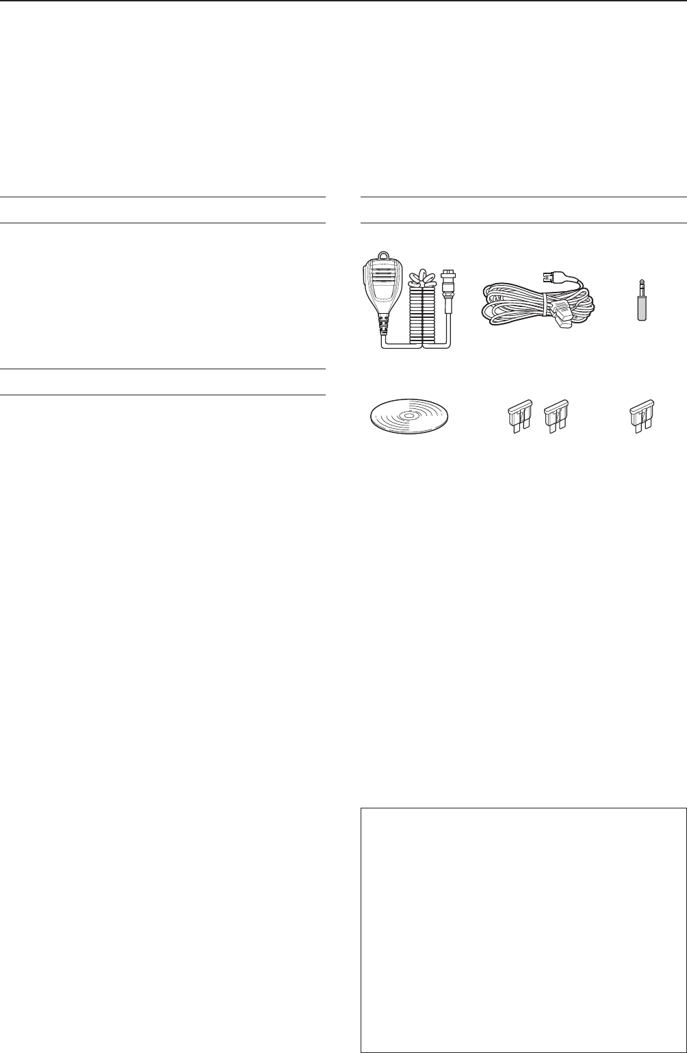
SUPPLIED ACCESSORIES
L Different types of accessories may be supplied, or may
not be supplied depending on the transceiver version.
IMPORTANT
READ ALL INSTRUCTIONS carefully completely
before using the transceiver.
SAVE THIS INSTRUCTION MANUAL— This instruction
manual contains basic operating instructions for the IC-
7610. For the advanced operating instructions, see the
Advanced Manual on the supplied CD.
This product includes RTOS “RTX” software, and is
licensed according to the software license.
This product includes “zlib” open source software,
and is licensed according to the open source
software license.
This product includes “libpng” open source software,
and is licensed according to the open source
software license.
Refer to the Text les in the License folder of
included CD for information on the open source
software being used by this product.
Icom is not responsible for the destruction, damage to, or
performance of any Icom or non-Icom equipment, if the
malfunction is because of:
• Force majeure, including, but not limited to, res,
earthquakes, storms, oods, lightning, or other natural
disasters, disturbances, riots, war, or radioactive
contamination.
• The use of Icom transceivers with any equipment that is
not manufactured or approved by Icom.
Hand microphone
(HM-219)
DC power cable
(3 m: 9.8 ft)
Spare fuse
(30 A)
Spare fuse
(5 A)
CW key plug
(6.35 mm: 1/4" Stereo)
CD
ii
This equipment has been tested and found to comply
with the limits for a Class B digital device, pursuant
to part 15 of the FCC Rules. These limits are
designed to provide reasonable protection against
harmful interference in a residential installation. This
equipment generates, uses and can radiate radio
frequency energy and, if not installed and used in
accordance with the instructions, may cause harmful
interference to radio communications. However, there
is no guarantee that interference will not occur in a
particular installation. If this equipment does cause
harmful interference to radio or television reception,
which can be determined by turning the equipment
off and on, the user is encouraged to try to correct
the interference by one or more of the following
measures:
• Reorient or relocate the receiving antenna.
• Increase the separation between the equipment
and receiver.
• Connect the equipment into an outlet on a
circuit different from that to which the receiver is
connected.
• Consult the dealer or an experienced radio/TV
technician for help.
WARNING: MODIFICATION OF THIS DEVICE
TO RECEIVE CELLULAR RADIOTELEPHONE
SERVICE SIGNALS IS PROHIBITED UNDER FCC
RULES AND FEDERAL LAW.
CAUTION: Changes or modications to this device,
not expressly approved by Icom Inc., could void
your authority to operate this device under FCC
regulations.
FCC INFORMATION TRADEMARKS
Icom, Icom Inc. and the Icom logo are registered trademarks
of Icom Incorporated (Japan) in Japan, the United States,
the United Kingdom, Germany, France, Spain, Russia,
Australia, New Zealand and/or other countries.
Microsoft, Windows and Windows Vista are registered
trademarks of Microsoft Corporation in the United States
and/or other countries.
Adobe, Acrobat, and Reader are either registered
trademarks or trademarks of Adobe Systems Incorporated
in the United States and/or other countries.
All other products or brands are registered trademarks or
trademarks of their respective holders.
WORD DEFINITION
R DANGER! Personal death, serious injury or an
explosion may occur.
R WARNING! Personal injury, fire hazard or electric
shock may occur.
CAUTION Equipment damage may occur.
NOTE
Recommended for optimum use. No
risk of personal injury, fire or electric
shock.
EXPLICIT DEFINITIONS
ABOUT CE AND DOC
Hereby, Icom Inc. declares that the versions of IC-7610 which have the “CE” symbol on the product, comply
with the essential requirements of the Radio Equipment Directive, 2014/53/EU, and the restriction of the use of
certain hazardous substances in electrical and electronic equipment Directive, 2011/65/EU. The full text of the EU
declaration of conformity is available at the following internet address:
http://www.icom.co.jp/world/support
DISPOSAL
The crossed-out wheeled-bin symbol on your product, literature, or packaging reminds you that in
the European Union, all electrical and electronic products, batteries, and accumulators
(rechargeable batteries) must be taken to designated collection locations at the end of their
working life. Do not dispose of these products as unsorted municipal waste.
Dispose of them according to the laws in your area.
ABOUT SPURIOUS SIGNALS
Spurious signals may be received near the following
frequencies. These are made in the internal circuit and
does not indicate a transceiver malfunction:
• 28.671 MHz • 50.516 MHz • 51.881 MHz
• 53.246 MHz • 53.760 MHz
iii
DTouch operation
In the Full manual or Basic manual, the touch
operation is described as shown below.
Touch
If the display is touched briey, one short beep
sounds.
Touch for 1 second
If the display is touched for 1 second, one
short and one long beep sound.
DTouch screen precautions
• The touch screen may not properly work when the
LCD protection lm or sheet is attached.
• Touching the screen with your nger nails, sharp
topped object and so on, or touching the screen
hard may damage it.
• Tablet PC’s operations such as ick, pinch in and
pinch out cannot be performed on this touch screen.
DTouch screen maintenance
• If the touch screen becomes dusty or dirty, wipe it
clean with a soft, dry cloth.
• When you wipe the touch screen, be careful not to
push it too hard or scratch it with your nger nails.
Otherwise you may damage the screen.
The following items are included on the CD.
•Basic manual (English)
Instructions for basic operations, the same as this
manual.
•Advanced manual (English)
Instructions for advanced operations in English.
• Basic manual (Multi-language)
Instructions for basic operations in multiple
languages.
•Schematic diagram
Includes the schematic and block diagrams.
•HAM radio Terms (English)
A glossary of HAM radio terms in English.
•Adobe® Reader® Installer
Installer for Adobe® Reader®.
A PC with the following Operating System is required.
• Microsoft® Windows® 10
• Microsoft® Windows® 8.1
• Microsoft® Windows® 7
To read the manuals or Schematic diagram, Adobe®
Acrobat® Reader® is required. If you have not
installed it, please install the Adobe Acrobat Reader
on the CD or download it from Adobe Systems
Incorporated’s website.
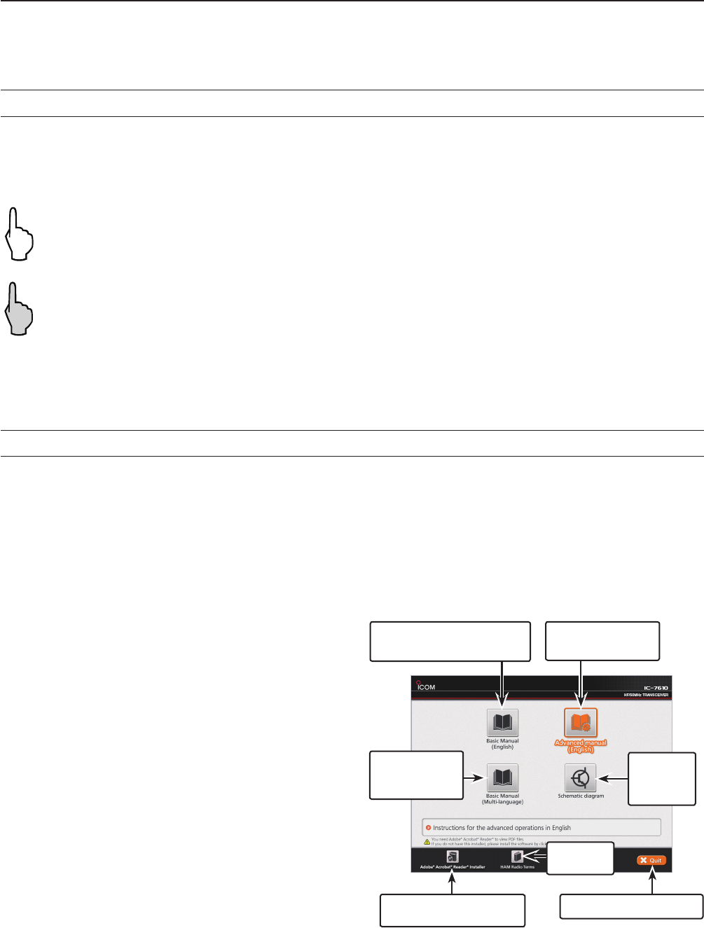
Starting the CD
1. Insert the CD into the CD drive.
2. Double click “Menu.exe” on the CD.
• Depending on the PC setting, the menu screen shown
below is automatically displayed.
3. Click the desired button to open the file.
L To close the Menu screen, click [Quit].
ABOUT THE TOUCH SCREEN
ABOUT THE SUPPLIED CD
L Different types of menu screen may be displayed,
depending on the transceiver version.
Closes the Menu screen
Installs Adobe® Acrobat®
Reader®
Opens the
multi-language
Basic manual
Opens the
Schematic
diagram
Opens the
Glossary
Opens the English
Basic manual (this manual)
Opens the English
Advanced manual

iv
ABOUT THE CONSTRUCTION OF THE MANUAL
There are two different types of manuals for this transceiver, the Basic manual (this manual) and the Advanced
manual.
DBasic manual (This manual)
Instructions for the basic operations, precautions, installations and connections.
DAdvanced manual (PDF type)
Instructions for the advanced operations, such as listed below and more...
L The Advanced manual is on the CD that is supplied with the transceiver, or can be downloaded from the Icom website.
http://www.icom.co.jp/world/support
• User Band Edge
• IP Plus function
• Main/Sub Band Tracking function
• Adjusting the Drive Gain level
• VOX function
•∂TX function
• Operating CW <Advanced>
• Operating RTTY (FSK) and PSK
• Data mode (AFSK) operation
• Scope operation <Advanced>
• Voice Recorder functions
• Voice TX Memory operation
• Using an SD card and USB ash drive <Advanced>
• Memory operation
• Scan
• Set mode <Advanced>
• Clock and Timers <Advanced>
• Updating the rmware
• Replacing fuse
• Cleaning
And more....
v
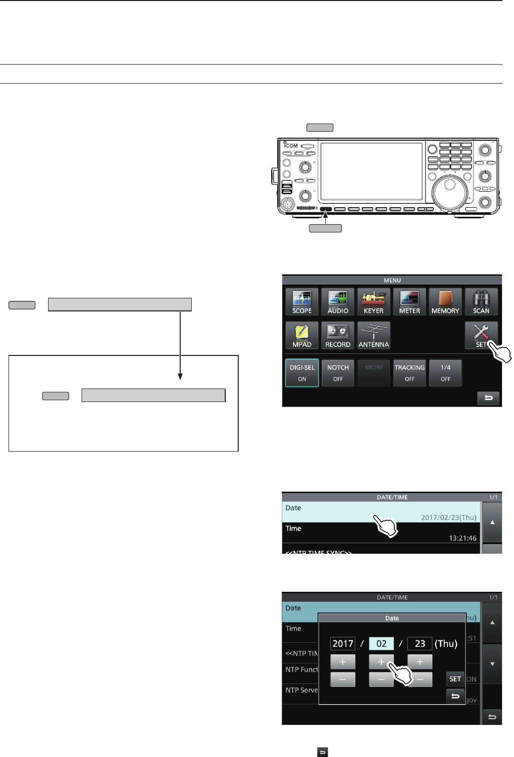
ABOUT THE INSTRUCTIONS
Instruction example
MENU
» SET > Time Set > Date/Time
Detailed instruction
1. Push
MENU
.
• Opens the MENU screen.
2. Touch [SET].
• Opens the SET screen.
3. Touch “Time Set.”
• Opens the TIME SET screen.
4. Touch “Date/Time.”
• Opens the DATE/TIME screen.
5. Touch “Date.”
• Opens the date editing screen.
6. Touch [+] and [-] to set the date.
The Basic and Advanced manuals are described in
the following manner.
“ ” (Quotation marks):
Used to indicate icons, setting items, and screen titles
displayed on the screen.
The screen titles are also indicated in uppercase
letters. (Example: FUNCTION screen)
[ ] (brackets):
Used to indicate keys.
Routes in the set modes and setting screens
Routes in the set mode, setting screen and the setting
items are described in the following manner.
7. Touch [SET] to set the date.
LTouch to cancel.
• Returns to the previous screen.
DSetting the current date
1. Open the DATE/TIME screen.
MENU
» SET > Time Set > Date/Time
2. Touch “Date/Time.”
3. Touch “Date.”
• Opens the date editing screen.
MENU

vi
TABLE OF CONTENTS
IMPORTANT ............................................................... i
FEATURES ................................................................. i
SUPPLIED ACCESSORIES ....................................... i
FCC INFORMATION ..................................................ii
TRADEMARKS ...........................................................ii
EXPLICIT DEFINITIONS ............................................ii
DISPOSAL ..................................................................ii
ABOUT CE AND DOC ................................................ii
ABOUT THE TOUCH SCREEN ................................iii
ABOUT THE SUPPLIED CD .....................................iii
ABOUT THE CONSTRUCTION OF THE MANUAL ..iv
ABOUT THE INSTRUCTIONS .................................. v
PRECAUTIONS ....................................................... viii
1. PANEL DESCRIPTION .................................... 1-1
Front panel ....................................................... 1-1
Rear panel ........................................................ 1-3
Touch screen display ........................................ 1-4
DMENU screen ............................................. 1-6
DMulti-function menus .................................. 1-6
DMulti-function key group ............................. 1-7
DQUICK MENU ............................................ 1-7
Keyboard entering and editing ......................... 1-8
DKeyboard types .......................................... 1-8
DEntering and editing ................................... 1-8
DEntering and editing example ..................... 1-9
2. INSTALLATION AND CONNECTIONS ........... 2-1
Using the desktop stands ................................. 2-1
Selecting a location .......................................... 2-1
Heat dissipation ................................................ 2-1
Grounding ......................................................... 2-1
Connecting an external DC power supply ....... 2-1
Connecting the antenna tuner .......................... 2-2
Connecting a Transverter ................................. 2-2
Linear amplier connections ............................. 2-3
DConnecting the IC-PW1/IC-PW1EURO ..... 2-3
DConnecting a non-Icom linear amplier ...... 2-3
3. BASIC OPERATION ........................................ 3-1
When rst applying power ................................ 3-1
Turning power ON or OFF ................................ 3-1
Adjusting the volume level ................................ 3-1
Selecting the VFO and Memory modes ........... 3-1
Selecting the Main and Sub bands ................... 3-2
DSwitching the Main band and Sub band ..... 3-2
Dualwatch operation ......................................... 3-2
DUsing the Dualwatch operation .................. 3-2
Selecting the operating band ............................ 3-3
D
Selecting the operating band
on the keypad ............................................. 3-3
D Selecting the operating band
on the screen ............................................. 3-3
Selecting the operating mode ........................... 3-3
Setting the frequency ....................................... 3-4
DUsing the Main Dial .................................... 3-4
DSetting the Tuning Step function ................ 3-4
DChanging the Tuning Step .......................... 3-4
D Using the 1 Hz step Fine Tuning function .. 3-4
DUsing the 1/4 Tuning function ..................... 3-5
DUsing the Auto Tuning Step function .......... 3-5
DDirectly entering a frequency ..................... 3-5
Dial Lock function ............................................. 3-6
RF gain and SQL level ..................................... 3-7
Meter display .................................................... 3-7
DSelecting the Meter readout ....................... 3-7
DAbout the Multi-function meter ................... 3-7
DDisplaying the Multi-function meter ............ 3-8
Adjusting the transmit output power ................. 3-8
DAdjusting the transmit output power ........... 3-8
Adjusting the microphone gain ......................... 3-9
Basic transmission ........................................... 3-9
4. RECEIVING AND TRANSMITTING ................. 4-1
Preampliers .................................................... 4-1
Attenuator ......................................................... 4-1
RIT function ......................................................4-1
DUsing the RIT Monitor function ................... 4-1
AGC function control ........................................ 4-2
D Selecting the AGC time constant
preset value ............................................... 4-2
DSetting the AGC time constant ................... 4-2
Using the Twin PBT .......................................... 4-3
Selecting the IF lter ......................................... 4-4
Selecting the IF lter shape .............................. 4-4
Noise Blanker ................................................... 4-5
DAdjusting the NB level and time ................. 4-5
Noise Reduction ............................................... 4-5
DAdjusting the Noise Reduction level ........... 4-5
Digital Selector ................................................. 4-6
DTurning ON the Digital Selector function .... 4-6
DAdjusting the center frequency ................... 4-6
Notch Filter ....................................................... 4-6
DSelecting the Notch function type ............... 4-6
DAuto Notch function .................................... 4-6
DManual Notch function ............................... 4-7
Monitor function ................................................ 4-7
Speech Compressor (SSB) .............................. 4-8
Auto Tuning function (AM/CW) ......................... 4-8
Split frequency operation .................................. 4-9
DUsing the Quick Split function .................... 4-9
D Using the receive and transmit frequencies
set to Main and Sub ................................... 4-9
Split Lock function .......................................... 4-10
Setting the transmit lter width ....................... 4-10

vii
TABLE OF CONTENTS (Continued)
Operating CW ................................................. 4-10
DSetting the CW pitch control ..................... 4-10
DSetting the keying speed .......................... 4-11
DUsing the Break-in function ...................... 4-11
DMonitoring the CW side tone .................... 4-12
DAPF (Audio Peak Filter) operation ........... 4-12
DAbout the Electronic Keyer function ......... 4-13
5. SCOPE OPERATION ....................................... 5-1
Spectrum scope screen .................................... 5-1
DMarker ........................................................ 5-1
DUsing the Spectrum Scope ........................ 5-1
DDisplaying the Mini scope screen ............... 5-2
Audio scope screen .......................................... 5-2
DUsing the Audio scope ............................... 5-2
DAUDIO SCOPE SET screen .......................5-3
6. SD CARD/USB FLASH DRIVE ....................... 6-1
About the SD cards .......................................... 6-1
About the USB ash drive ................................ 6-1
Saving data ...................................................... 6-1
Inserting ............................................................ 6-1
Formatting ........................................................ 6-2
D Formatting the SD card or
USB ash drive .......................................... 6-2
Unmounting ...................................................... 6-2
7. ANTENNA TUNER OPERATION .................... 7-1
About the Antenna memory settings ................ 7-1
DThe Antenna memory screen ..................... 7-1
DSaving an antenna connector setting ......... 7-1
DSelecting the antenna type ......................... 7-2
About the internal antenna tuner ...................... 7-2
Using the Internal antenna tuner ...................... 7-3
DManual tuning ............................................. 7-3
DPTT Tuner start .......................................... 7-3
About an external antenna tuner ...................... 7-3
DUsing the AH-4 or AH-740 .......................... 7-3
DUsing an external antenna tuner ................ 7-4
Emergency mode (Tuner) ................................. 7-4
8. SET MODE ....................................................... 8-1
Set mode description ........................................ 8-1
DEntering the Set mode ............................... 8-1
Tone Control .................................................... 8-2
Function ............................................................ 8-2
Connectors ....................................................... 8-5
Network ............................................................ 8-7
Display .............................................................. 8-8
Time Set ........................................................... 8-9
SD Card ............................................................ 8-9
USB Flash Drive ............................................. 8-10
Others ............................................................. 8-10
9. CLOCK AND TIMERS ..................................... 8-1
Setting the date and time ................................. 9-1
DSetting the date .......................................... 9-1
DSetting the current time .............................. 9-1
DSetting the UTC offset ................................ 9-1
DDisplaying CLOCK2 ................................... 9-1
DSetting the CLOCK2 UTC offset ................. 9-2
DEditing the CLOCK2 name ......................... 9-2
10. MAINTENANCE ............................................. 10-1
Resetting ........................................................ 10-1
DPartial reset .............................................. 10-1
DAll reset .................................................... 10-1
Troubleshooting .............................................. 10-2
11. SPECIFICATIONS ......................................... 11-1
DGeneral .................................................... 11-1
DTransmitter ............................................... 11-1
DReceiver ................................................... 11-2
DAntenna tuner ........................................... 11-2
12. OPTIONS ....................................................... 12-1
13. CONNECTOR INFORMATION ...................... 12-1
Interface information ....................................... 13-1
ACC sockets ................................................... 13-2
PHONES ........................................................ 13-3
ELEC-KEY ......................................................13-3
KEY ................................................................13-3
DC 13.8 V ....................................................... 13-3
TUNER ........................................................... 13-3
MIC ................................................................. 13-3
EXT KEYPAD ................................................. 13-4
REMOTE ........................................................ 13-4
METER ........................................................... 13-4
USB port (type A) ........................................... 13-4
ALC ................................................................ 13-4
SEND ............................................................. 13-4
LAN ................................................................ 13-5
EXT-DISPLAY ................................................. 13-5
USB 2 ............................................................. 13-5
USB 1 ............................................................. 13-5
EXT-SP A / EXT-SP B ..................................... 13-5
REF IN ............................................................ 13-5
X-VERTER .....................................................13-6
ANT 1 / ANT 2 ................................................13-6
RX-ANT IN/OUT ............................................. 13-6
INSTALLATION NOTES ............................................ I
INDEX........................................................................ II

viii
PRECAUTIONS
R DANGER HIGH RF VOLTAGE! NEVER touch an
antenna or antenna connector while transmitting. This could
cause an electrical shock or burn.
R DANGER! NEVER operate the transceiver near
unshielded electrical blasting caps or in an explosive
atmosphere. This could cause an explosion and death.
R WARNING RF EXPOSURE! This device emits Radio
Frequency (RF) energy. Extreme caution should be
observed when operating this device. If you have any
questions regarding RF exposure and safety standards
please refer to the Federal Communications Commission
Ofce of Engineering and Technology’s report on
Evaluating Compliance with FCC Guidelines for Human
Radio Frequency Electromagnetic Fields (OET Bulletin 65).
R WARNING! NEVER operate the transceiver with a
headset or other audio accessories at high volume levels. If
you experience a ringing in your ears, reduce the volume or
discontinue use.
R WARNING! NEVER apply AC power to the [DC13.8V]
socket on the transceiver rear panel. This could cause a re
or damage the transceiver.
R WARNING! NEVER apply more than 16 V DC to the
[DC13.8V] socket on the transceiver rear panel. This could
cause a re or damage the transceiver.
R WARNING! NEVER reverse the DC power cable
polarity. This could cause a re or damage the transceiver.
R WARNING! NEVER remove the fuse holder on the DC
power cable. Excessive current caused by a short could
cause a re or damage the transceiver.
R WARNING! NEVER let metal, wire or other objects
contact the inside of the transceiver, or make incorrect
contact with connectors on the rear panel. This could cause
an electric shock or damage the transceiver.
R WARNING! NEVER operate or touch the transceiver
with wet hands. This could cause an electric shock or
damage to the transceiver.
R WARNING! NEVER operate the equipment if you notice
an abnormal odor, sound or smoke. Immediately turn OFF
the power and/or remove the DC power cable. Contact your
Icom dealer or distributor for advice.
R WARNING! NEVER put the transceiver on an unstable
place where the transceiver may suddenly move or fall.
This could cause an injury or damage the transceiver.
R WARNING! NEVER operate the transceiver during a
lightning storm. It may result in an electric shock, cause
a re or damage the transceiver. Always disconnect the
power source and antenna before a storm.
CAUTION: DO NOT expose the transceiver to rain, snow
or any liquids. They could damage the transceiver.
CAUTION: DO NOT change the internal settings of the
transceiver. This may reduce transceiver performance and/
or damage the transceiver. The transceiver warranty does
not cover any problems caused by unauthorized internal
adjustments.
CAUTION: DO NOT install the equipment in a place
without adequate ventilation, or block any cooling vents
on the top, rear, sides or bottom of the transceiver or the
cooling fan. Heat dissipation may be reduced and damage
the transceiver.
CAUTION: DO NOT use harsh solvents such as benzine or
alcohol when cleaning. This could damage the equipment
surfaces. If the surface becomes dusty or dirty, wipe it clean
with a soft, dry cloth.
CAUTION: DO NOT place or leave the transceiver in
areas with temperatures below 0°C (32°F) or above 50°C
(122°F).
CAUTION: DO NOT place the transceiver in excessively
dusty environments, or in direct sunlight. This could
damage the transceiver.
CAUTION: DO NOT set the transceiver’s RF output power
to more than a connected linear amplier’s maximum input
level. Otherwise, the linear amplier will be damaged.
CAUTION: DO NOT use non-Icom microphones. Other
microphones have different pin assignments and may
damage the transceiver.
BE CAREFUL! The transceiver will become hot when
operating the transceiver continuously for long periods of
time.
NEVER leave the transceiver in an insecure place to avoid
use by unauthorized persons.
Turn OFF the transceiver’s power and disconnect the DC
power cable when you will not use the transceiver for long
period of time.
The LCD display may have cosmetic imperfections
that appear as small dark or light spots. This is not a
malfunction or defect, but a normal characteristic of LCD
displays.
1PANEL DESCRIPTION
1-1
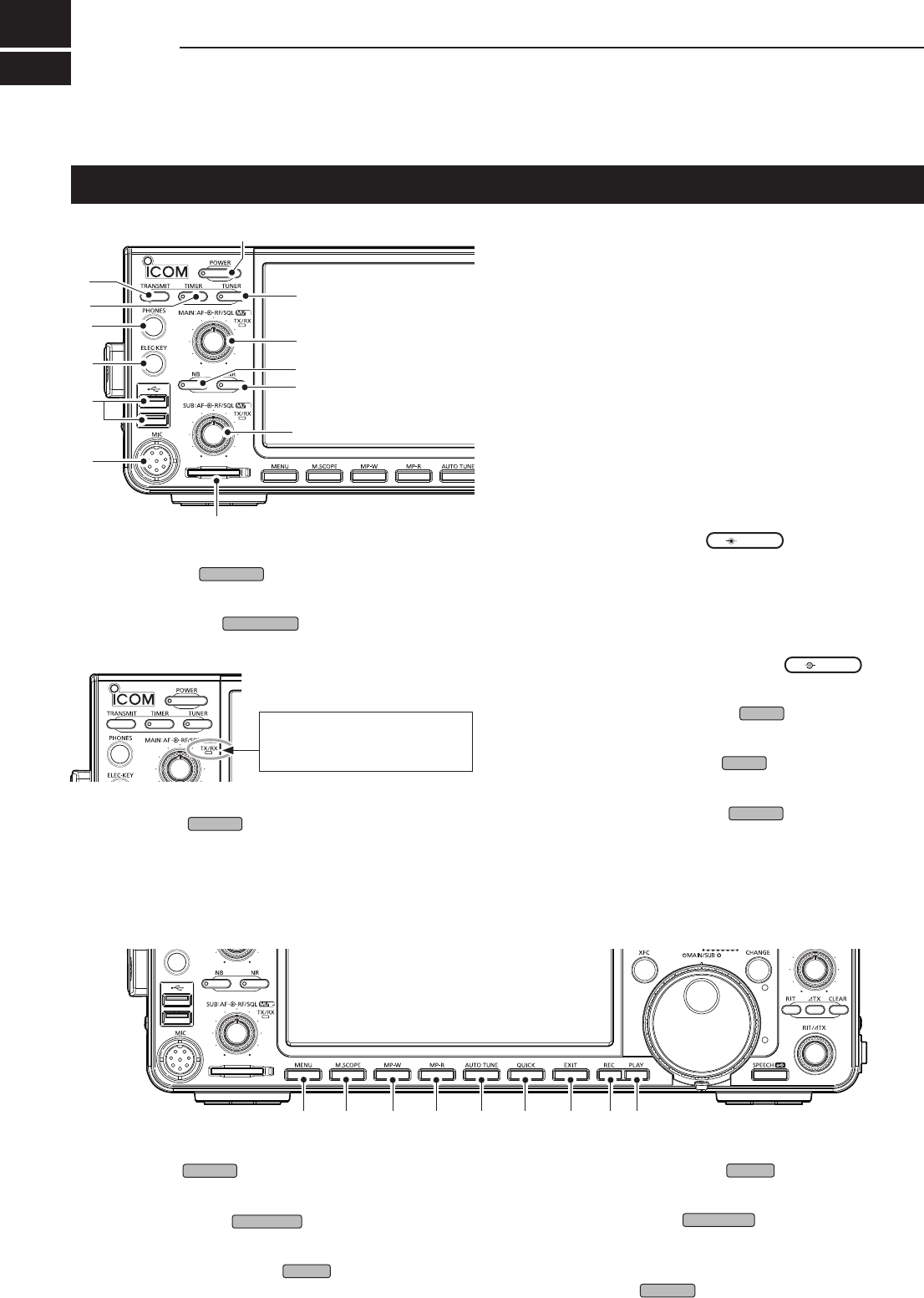
Front panel
q POWER KEY
POWER
(p. 3-1)
Turns the transceiver ON or OFF.
w TRANSMIT KEY
TRANSMIT
(p. 3-9)
Toggles between transmit and receive.
e TIMER KEY
TIMER
Turns the Sleep Timer or Daily Timer function ON or
OFF.
!3 !4 !5 !6 !7 !8 !9 @0 @1
r
t
y
u
!2
o
!0
w
q
e
!1
o
i
r HEADPHONE JACK [PHONES] (p. 13-3)
Connects to standard stereo headphones.
t ELECTRONIC KEYER JACK [ELEC-KEY] (p. 13-3)
Connects to a paddle to use the internal electronic
keyer for the CW operations.
y USB PORT [USB A] (p. 13-4)
InsertaUSBashdrive,USBAtypekeyboard,RC-
28 remote encoder,mouseorhub.
u MICROPHONE CONNECTOR [MIC] (p. 13-3)
Connects to the supplied or an optional microphone.
i SD CARD SLOT [SD CARD] (p. 6-1)
AcceptsanSDcard.Theindicatornexttotheslot
lights blue when inserted.
o VOLUME CONTROL
AF RF/SQL
(p. 3-1)
LTheuppercontrolisfortheMainband,andthe
lower control is for the Sub band.
• Push to turn the Mute function ON or OFF.
-TheTX/RXindicatorlightsorangewhenturnedON.
•Adjuststheaudiooutputlevel.
RF GAIN/SQUELCH CONTROL
AF RF/SQL
(p. 3-7)
AdjuststheRFgainandsquelchthresholdlevels.
!0 NOISE REDUCTION KEY
NR
(p. 6-5)
TurnstheNoiseReductionfunctionONorOFF.
!1 NOISE BLANKER KEY
NB
(p. 6-5)
Turns the Noise Blanker ON or OFF.
!2 ANTENNA TUNER KEY
TUNER
(p. 7-3)
TurnstheantennatunerONorOFF,oractivates
the tuner.
The TX/RX indicator
• Lights green while receiving.
• Lights red while transmitting.
!3 MENU KEY
MENU
(p. 8-1)
Displays the MENU screen.
!4 MINI SCOPE KEY
M.SCOPE
(p. 5-2)
Displays the Mini Scope or Spectrum Scope.
!5 MEMO PAD WRITE KEY
MP-W
Saves the displayed contents into the Memo Pad.
!6 MEMO PAD READ KEY
MP-R
SequentiallycallsupthecontentsintheMemoPad.
!7 AUTO TUNE KEY
AUTO
TUNE
(p. 4-8)
Automaticallytunestheoperatingfrequencytoa
received CW signal.
!8 QUICK KEY
QUICK
(p. 1-7)
Displays the QUICK MENU.
1
PANEL DESCRIPTION
1
2
3
4
5
6
7
8
9
10
11
12
13
14
15
16
17
18
19
20
21
1-2
@7 @8 @9
@2
@3
@4
#1
#3
#4
#2
#5
#7
#8
#0
#6
#9
@6
@5
$0
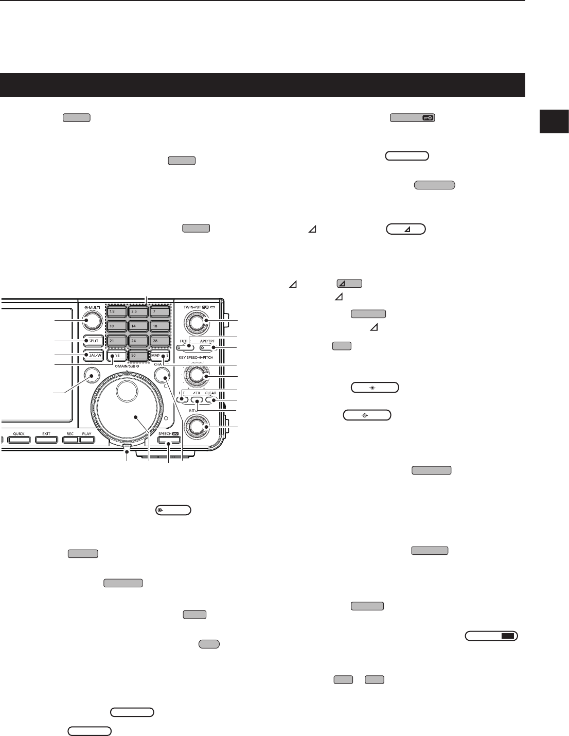
@2 MULTI-FUNCTION CONTROL
MULTI
(p. 1-6)
Displays the Multi-function menu for various
adjustments,orselectsanitem.
@3 SPLIT KEY
SPLIT
(p. 4-9)
Turns the Split function ON or OFF.
@4 DUALWATCH KEY
DUAL-W
(p. 3-2)
Turns the Dualwatch function ON or OFF.
@5 GENERAL COVERAGE BAND KEY
GENE
Selects the general coverage band.
@6 TRANSMIT FREQUENCY CHECK KEY
XFC
(p. 4-1, 4-9, 4-10)
Enablesyoutomonitorthetransmitfrequencywhile
holding it down in the Split mode.
@7 TENSION ADJUSTER
Adjuststhefrictionof
MAIN
DIAL
.
@8 MAIN DIAL
MAIN
DIAL
(p. 3-4)
Changestheoperatingfrequency.
Front panel (Continued)
@9 SPEECH/LOCK KEY
SPEECH
• Announcestheoperatingfrequencyandmodeby
pushing this key.
• Electronically locks
MAIN
DIAL
by holding down
this key for 1 second.
#0 MAIN/SUB CHANGE KEY
CHANGE
(p. 3-2)
Togglesthefrequency,modeandselectedmemory
channel between the Main and Sub band.
#1 RIT/ TX CONTROL
RIT/ TX
(p. 4-1)
Shiftsthereceiveortransmitfrequencyupto
±9.99 kHz without changing the transmit or receive
frequency.
#2 TX KEY
TX
Turns the TX function ON or OFF.
#3 CLEAR KEY
CLEAR
ClearstheRITor TXshiftfrequency.
#4 RIT KEY
RIT
(p. 4-1)
TurnstheReceiverIncrementalTuning(RIT)
function ON or OFF.
#5 KEY SPEED
KEY
SPEED
PITCH
CONTROL (p. 4-11)
AdjuststheinternalelectronicCWkeyerspeed.
CW PITCH
KEY
SPEED
PITCH
CONTROL (p. 4-10)
Shifts the received CW audio pitch and the CW
side tone pitch without changing the operating
frequency.
#6 MAIN/SUB ACCESS KEY
MAIN/SUB
(p. 3-2)
SelectstheMainorSubbandfrequencyreadout.
• Theselectedband’sfrequencyisdisplayedclearly
whereasthenon-selectedband’sfrequencyis
displayed in gray.
#7 AUDIO PEAK FILTER/
TWIN PEAK FILTER KEY
APF/TPF
(p. 4-12)
IntheCWmode,turnstheAudioPeakFilterONor
OFF,andintheRTTYmode,turnstheTwinPeak
Filter ON or OFF.
#8 FILTER KEY
FILTER
(p. 4-4)
SelectsoneofthreeIFlters.
#9
TWIN PASSBAND TUNING CONTROL
TWIN PBT
CLR
(p. 4-3)
AdjuststheIFlter’spassbandwidth.
$0 KEYPAD
1.8
~
50
Selectstheoperatingbandbypushingonce,orcall
upotherstackedfrequenciesbypushingthesame
key several times.
!9 EXIT KEY
EXIT
Exitsasettingscreenorreturnstotheprevious
screen.
@0 VOICE MEMORY RECORD KEY
REC
Saves the previously received signal for the preset
timeperiodsetinRECTime,usingtheInstant
Replayfunction,orstartsrecordingaQSOaudio
onto an SD card.
@1 VOICE MEMORY PLAY BACK KEY
PLAY
Playsbackthelast5secondsoftheInstantReplay
memory,oralloftheInstantReplaymemory.
1PANEL DESCRIPTION
1-3
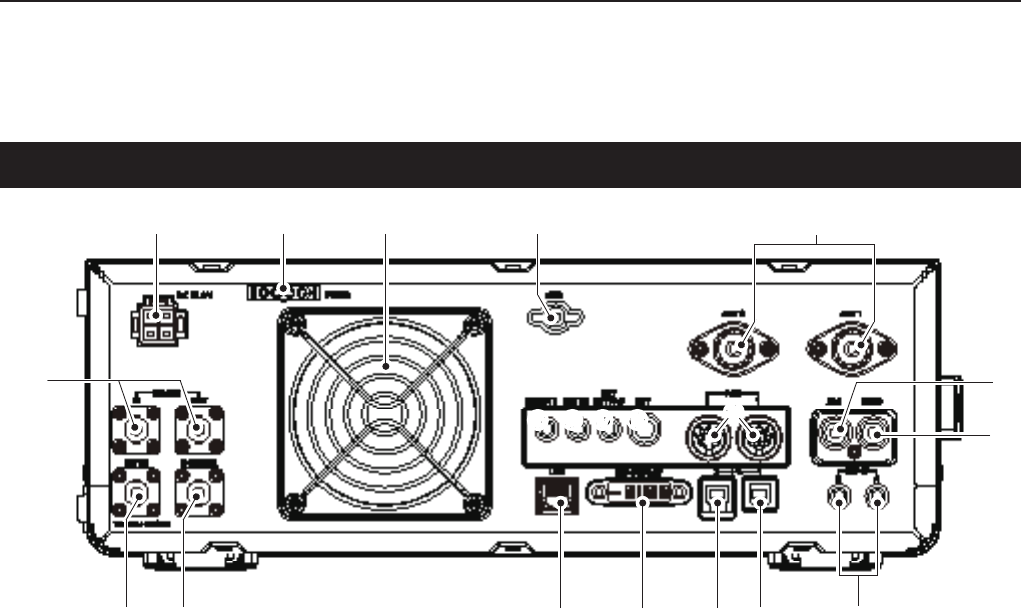
q DC POWER SOCKET [DC 13.8 V]
Connects to 13.8 V DC through the DC power
cable.
w TUNER CONTROL SOCKET [TUNER]
Acceptsthecontrolcablefromanoptional
AH-4 orAH-740automatic antenna tuner.
e COOLING FAN
CoolsthePAunitwhennecessary.
r GROUND TERMINAL [GND]
Connectstogroundtopreventelectricalshocks,
TVI,BCIandotherproblems.
t ANTENNA CONNECTOR [ANT1]/[ANT2]
Connectstoa50Ωantenna.IfyouusetheAH-4or
AH-740,youmustconnecttheantennato[ANT1].
y ALC INPUT JACK [ALC]
ConnectstotheALCoutputjackofanon-Icom
linearamplier.
u SEND CONTROL JACK [SEND]
Connectstocontroltransmitwithnon-Icomexternal
units.
i EXTERNAL SPEAKER JACK A/B [EXT-SP]
Acceptsa4~8Ωexternalspeaker.
o USB PORT [USB 1] (Type B)
Connects to a PC for remote control operations.
!0 USB PORT [USB 2] (Type B)
For digital data input or output.
!1 EXTERNAL DISPLAY CONNECTOR
[EXT-DISPLAY]
Connectstoanexternaldisplaymonitor.
!2 ETHERNET CONNECTOR [LAN]
ConnectstoaPCnetworkthroughaLAN.
!3 TRANSVERTER CONNECTOR [X-VERTER]
Connectstoanexternaltransverterforinput/output.
!4 REFERENCE SIGNAL INPUT [REF IN]
Inputfora10MHzreferencesignalthroughthe
BNC connector.
!5 RECEIVE ANTENA [RX ANT–IN]/[RX ANT–OUT]
Connectstoanexternalunit,suchaspreamplier
orRFlter,usingBNCconnectors.
• This is located between the transmit/receive switching
circuitandreceiver’sRFstage.
!6 CI-V REMOTE CONTROL JACK [REMOTE]
Connects to a PC or other transceiver for remote
control.
!7 METER JACK [METER]
Outputsreceivedsignalstrength,transmitoutput
power,VSWR,ALC,speechcompression,Vd or Id
levelsforanexternalmeter.
!8 EXTERNAL KEYPAD JACK [EXT KEYPAD]
(p. 13- 4)
Connectstoanexternalkeypadfordirectvoice
memory,memorykeyer,RTTYmemoryorPSK
memory transmission.
!9 STRAIGHT KEY JACK [KEY]
Connectstoastraightkey,paddle,oranexternal
electronic keyer with 6.35 mm (¼ in) stereo plug.
@0 ACC SOCKET [ACC1]/[ACC2]
Connectstodevicestocontrolanexternalunitorto
control the transceiver.
Rear panel
q ew r
!5
!4 !3 !2 !1 o i
y
!6 !7 !8!5 !9
t
u
!0
1
PANEL DESCRIPTION
1
2
3
4
5
6
7
8
9
10
11
12
13
14
15
16
17
18
19
20
21
1-4
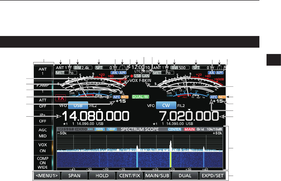
Touch screen display
q MULTI-FUNCTION KEY GROUP
Displays the Multi-function keys.
w ANTENNA INDICATOR (p. 7-1)
Displays the selected antenna connector between
ANT1andANT2.
e METER TYPE INDICATOR (p. 3-7)
Displays the selected transmit parameter type.
SelectbetweenPo,SWR,ALC,COMP,Vd and Id.
r BANDWIDTH INDICATOR (p. 4-3, 4-4)
DisplaysthepassbandwidthoftheIFlter.
t SHIFT FREQUENCY INDICATOR (p. 4-3)
DisplaystheshiftfrequencyoftheIFlter.
y NOTCH INDICATOR (p. 4-6)
“AN”isdisplayedwhentheAutoNotchfunctionis
ON,and“MN”isdisplayedwhentheManualNotch
function is ON.
u PASSBAND WIDTH INDICATOR (p. 4-3)
Displays the passband width for twin PBT operation
andthecenterfrequencyforIFshiftoperation.
i AUDIO PEAK FILTER (APF) INDICATOR (p. 4-12)
DisplayedwhentheAudioPeakFilterisON.
o CLOCK READOUT (p. 9-1)
Displays the time (2 types) set on the TIME SET
screen.
!0 USB INDICATOR (p. 6-1)
DisplayedwhileaUSBasheddriveisinserted.
!1 LAN INDICATOR
Displayed while the transceiver and the optional
RS-BA1areconnectedthroughtheLANforremote
control operation.
!2 BK-IN/F-BKIN INDICATOR (p. 4-11)
Displayed while the Semi Break-in or Full Break-in
function is ON.
!3 NET FUNCTION INDICATOR (p. 8-7)
Displayed when the NET function is ON while in the
PSK mode.
!4 FREQUENCY OFFSET READOUT
Displays the offset value between the PSK signal
andtheoperatingfrequency,whileaPSKsignalis
received.
!5 AFC FUNCTION INDICATOR
DisplayedwhiletheAutomaticFrequencyControl
(AFC)functionisON,inthePSKmode.
!6 FREQUENCY READOUT (p. 3-4)
Displaystheoperatingfrequency.
LThenon-selectedband’sfrequencyreadout(Mainor
Sub) is displayed in gray.
!7 FUNCTION DISPLAY
Displayed when an item that has a function display
isselected.Forexample,theSpectrumScope.
!8 FUNCTION KEYS (p. 5-1)
Displaystheoperatingparameters,modes,
frequenciesandindicators,andsoon.
!9 VOX INDICATOR
Displayed while the VOX function is ON.
@0 VOICE RECORDER ICON
• “●”isdisplayedwhilerecording.
• “”isdisplayedwhilepausing.
w r t oyeq i w r t uye i
!2
!3
!4
!5
!7
!8
!3
!5
!6
!4
!6
@0
!9
!1!0u
1PANEL DESCRIPTION
1-5
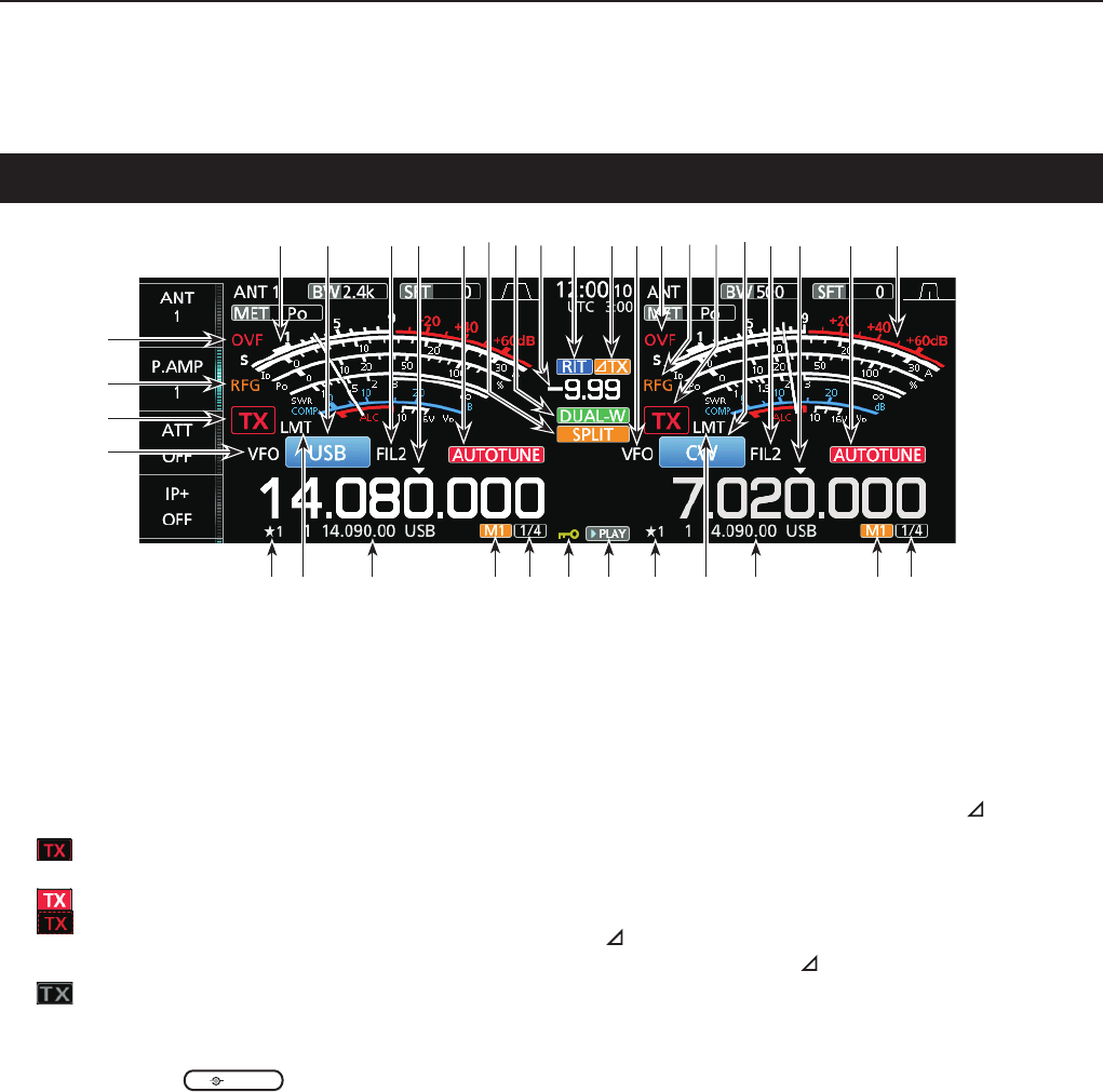
@1 VFO/MEMORY ICON (p. 3-1)
“VFO”isdisplayedwhentheVFOmodeisselected,
and the memory number is displayed when a
Memory channel is selected.
@2 TX STATUS INDICATOR (p. 3-4, 3-9)
Displays the transmit status of the displayed
frequency.
• isdisplayedwhilethedisplayedfrequencyiswithin
the amateur band range.
• (Redbackground)isdisplayedwhiletransmitting.
• (With a border of short dashes) is displayed when
theselectedfrequencyisoutsideoftheamateurband
frequency.
• (Grayed out) is displayed while the transmitter is
inhibited.
@3 RF GAIN INDICATOR (p. 3-7)
Displayed when
AF RF/SQL
(outer) is set
counterclockwise from the 11 o’clock position. The
indicatorshowsthattheRFgainisreduced.
@4 OVF ICON (p. 3-7)
“OVF”isdisplayedwhenanexcessivelystrong
signal is received.
@5 METER INDICATOR (p. 3-7)
DisplaystheS,Id,Po,SWR,COMP,ALCandVd
meters.
@6 MODE INDICATOR (p. 3-3)
Displays the selected operating mode.
@7 IF FILTER INDICATOR (p. 4-3, 4-4)
DisplaystheselectedIFlter.
@8 QUICK TUNING ICON (p. 3-4)
DisplayedwhenthequickTuningStepfunctionis
ON.
@9 AUTO TUNE INDICATOR (p. 4-8)
Displays“AUTOTUNE”whentheAutoTuning
function is ON.
Touch screen display (Continued)
#0 SPLIT ICON (p. 4-9)
Displayed when the Split function is ON.
#1 DUALWATCH ICON (p. 3-2)
Displayed when using Dualwatch.
#2 SHIFT FREQUENCY READOUT (p. 4-1)
DisplaystheshiftoffsetfortheRITor TX
functions,whilethesefunctionsareON.
#3 RIT ICON (p. 4-1)
DisplayedwhentheRITfunctionisON.
#4 TX ICON
Displayed when the TX function is ON.
#5 1/4 TUNING STEP INDICATOR (p. 3-5)
Displayedwhilethe1/4TuningStepfunctionisON.
#6 M1~M8/T1~T8
• Displays“M1”~“M8”whileusingtheMemoryKeyer
function is used.
• Displays“T1”~“T8”whileusingtheVoiceTXmemory
function.
#7 MEMORY CHANNEL/VFO READOUT (p. 3-1)
Displays the selected memory channel contents in
theVFOmode,anddisplaystheVFOcontentsin
the Memory mode.
#8 LMT ICON
Displayedifthepowerampliertemperature
becomesextremelyhighandtheprotectionfunction
is activated after transmitting continuously for long
periods of time.
#9 SELECT MEMORY CHANNEL ICON
Indicates that the displayed memory channel is
assigned as a Select memory channel (★1~★3).
$0 PLAY ICON
Displayed while playing the recorded voice audio.
$1 DIAL LOCK INDICATOR (p. 3-6)
Displayed while the Lock function is ON.
@6 @7 @7@9 @9@8 @8
#5#5 #6#7$0$1#7 #9 #8#8#9 #6
#3 #4 @1@5 @4 @5
@2
@1
@3
@4
#0 #1 @2@3#2 @6
1
PANEL DESCRIPTION
1
2
3
4
5
6
7
8
9
10
11
12
13
14
15
16
17
18
19
20
21
1-6
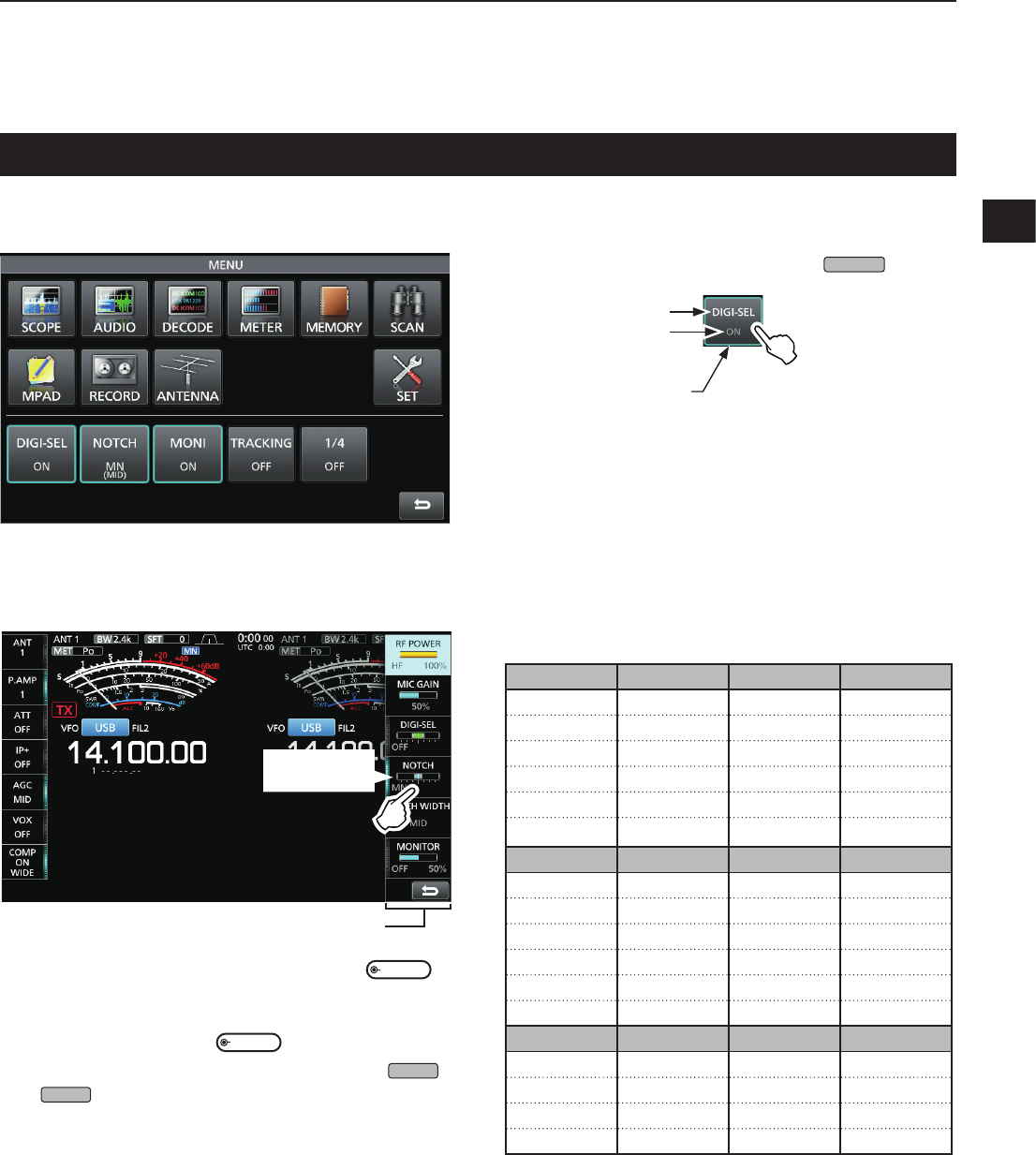
Touch screen display (Continued)
DMENU screen
zOpen the MENU screen by pushing
MENU
.
Function name
Status
Lights blue or orange
when in use
LTheitemsdisplayedonthemenudiffer,depending
on the selected operating mode.
DMulti-function menus
z Open the Multi-function menu by pushing
MULTI
(Multi-function control).
zWhiletheMulti-functionmenuisopen,touchthe
desired item and rotate
MULTI
toadjustthevalue.
LYoucanopenothermenusbyholdingdown
NB
or
NR
for1second,ortouching“ATT,”“VOX,”
“BK-IN”or“COMP”intheMulti-functionkeygroup
for 1 second.
Multi-function menu
Touch to turn
ON or OFF
SSB CW RTTY PSK
RFPOWER RFPOWER RFPOWER RFPOWER
MICGAIN
DIGI-SEL DIGI-SEL DIGI-SEL DIGI-SEL
NOTCH NOTCH NOTCH NOTCH
NOTCH WIDTH NOTCH WIDTH NOTCH WIDTH NOTCH WIDTH
MONITOR MONITOR MONITOR
AM FM NB NR
RFPOWER RFPOWER LEVEL LEVEL
MICGAIN MICGAIN DEPTH
DIGI-SEL DIGI-SEL WIDTH
NOTCH NOTCH
NOTCH WIDTH
MONITOR MONITOR
ATT VOX BK-IN COMP
LEVEL GAIN DELAY LEVEL
ANTIVOX TBW
DELAY
VOICEDELAY
Multi-function menu items
1PANEL DESCRIPTION
1-7
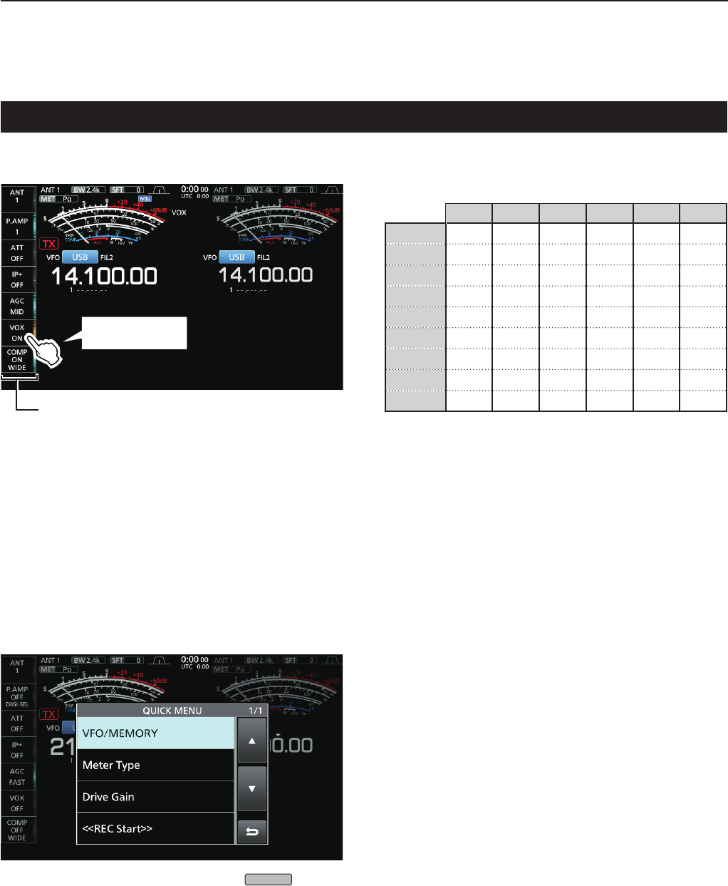
Touch screen display (Continued)
DQUICK MENU
z Open the QUICK MENU by pushing
QUICK
.
DMulti-function key group
Multi-function key group
Touch to turn ON
orOFF,ortoset
z Touch a key to turn the function ON or OFF.
zTouching“ATT,”“VOX,”“BK-IN”or“COMP”for1
secondopenstheATTmenu,VOXmenu,BK-IN
menu or COMP menu.
LSee“Multi-functionmenus”onthepreviouspagefor
details.
SSB CW RTTY PSK AM FM
ANT ✓✓✓✓✓✓
P.AMP ✓✓✓✓✓✓
ATT ✓✓✓✓✓✓
IP+ ✓✓✓✓✓✓
AGC ✓✓✓✓✓✓
VOX ✓ ✓ ✓
BK-IN ✓
COMP ✓
TONE ✓
Multi-function key group items
1
PANEL DESCRIPTION
1
2
3
4
5
6
7
8
9
10
11
12
13
14
15
16
17
18
19
20
21
1-8
Keyboard entering and editing
Youcanenterandedittheitemsonthefollowingscreens.
LUsablecharacters,symbols,andtheamountofcharactersthatcanbeentereddiffers,dependingontheeditingitem.
• MYCALL
• FILENAME
• NETWORKNAME
• NETWORKRADIONAME
• NETWORKUSER1ID
• NETWORKUSER2ID
• NETWORKUSER1PASSWORD
• NETWORKUSER2PASSWORD
• NTPSERVERADDRESS
• CLOCK2NAME
• KEYERMEMORY
• PSKMEMORY
• RTTYMEMORY
• VOICETXRECORD(T1)~(T8)
• MEMORYNAME
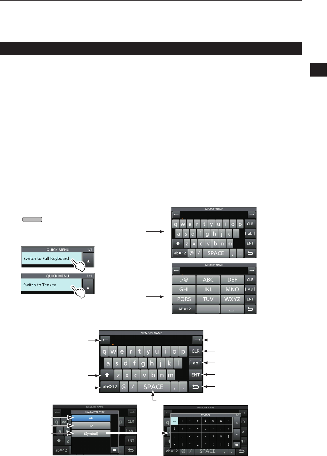
DKeyboard types
YoucanselecttheFullKeyboardorTenkeyby
pushing
QUICK
while displaying an entry mode
screen.
DEntering and editing
Clears the entered character
Selects alphabet mode
or number mode
Enters a space
Selects the character type
Saves the entry
Cancels entry and returns to the
previous screen
Enters an uppercase letter
Moves the cursor forward
Moves the cursor backward
Alphabetmode
Number mode
Symbol mode
1PANEL DESCRIPTION
1-9
Keypad entering and editing (Continued)
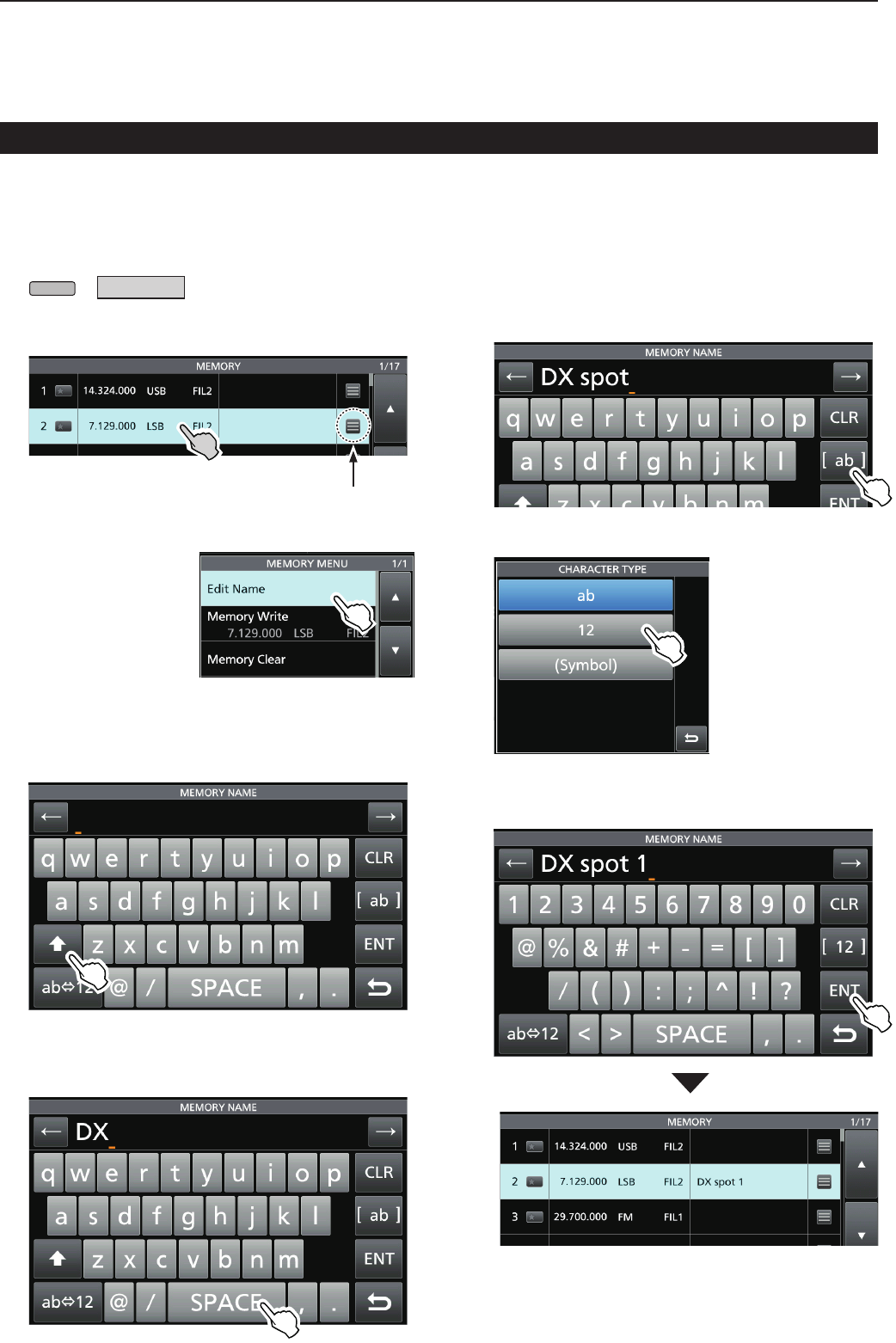
DEntering and editing example
Entering“DXspot1”intheMemorychannel2
1. DisplaytheMEMORYscreen.
MENU
» MEMORY
2. Touch the memory channel 2 for 1 second.
• TheMEMORYMENUscreenisdisplayed.
3. Touch“EditName.”
• TheMEMORY
NAMEscreenis
displayed.
4. Touch[],andthentouch[D].
LTouching[]changesbetweenuppercaseand
lowercase letter.
5. Touch[]again,andthentouch[X].
6. Touch[SPACE]toenteraspace.
7. Touch[s],[p],[o],andthen[t].
8. Touch[SPACE]toenteraspace.
9. Touch[ab].
• TheCHARACTERTYPEscreenisdisplayed.
10. Touch[12].
11. Touch[1].
12. Touch[ENT]tosavetheentry.
• Returnstothepreviousscreen.
YoucanalsodisplaytheMEMORY
MENU screen by touching this key.