ICOM orporated 386600 VHF/UHF DUAL BAND Transceiver User Manual
ICOM Incorporated VHF/UHF DUAL BAND Transceiver
UserManual.wiki
>
ICOM orporated
>
386600 User Manual
User manual
Navigation menu
Upload a User Manual
Namespaces
Wiki Guide
HTML
PDF
Info
Views
User Manual
Discussion / Help
Navigation
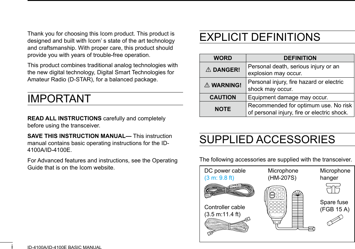

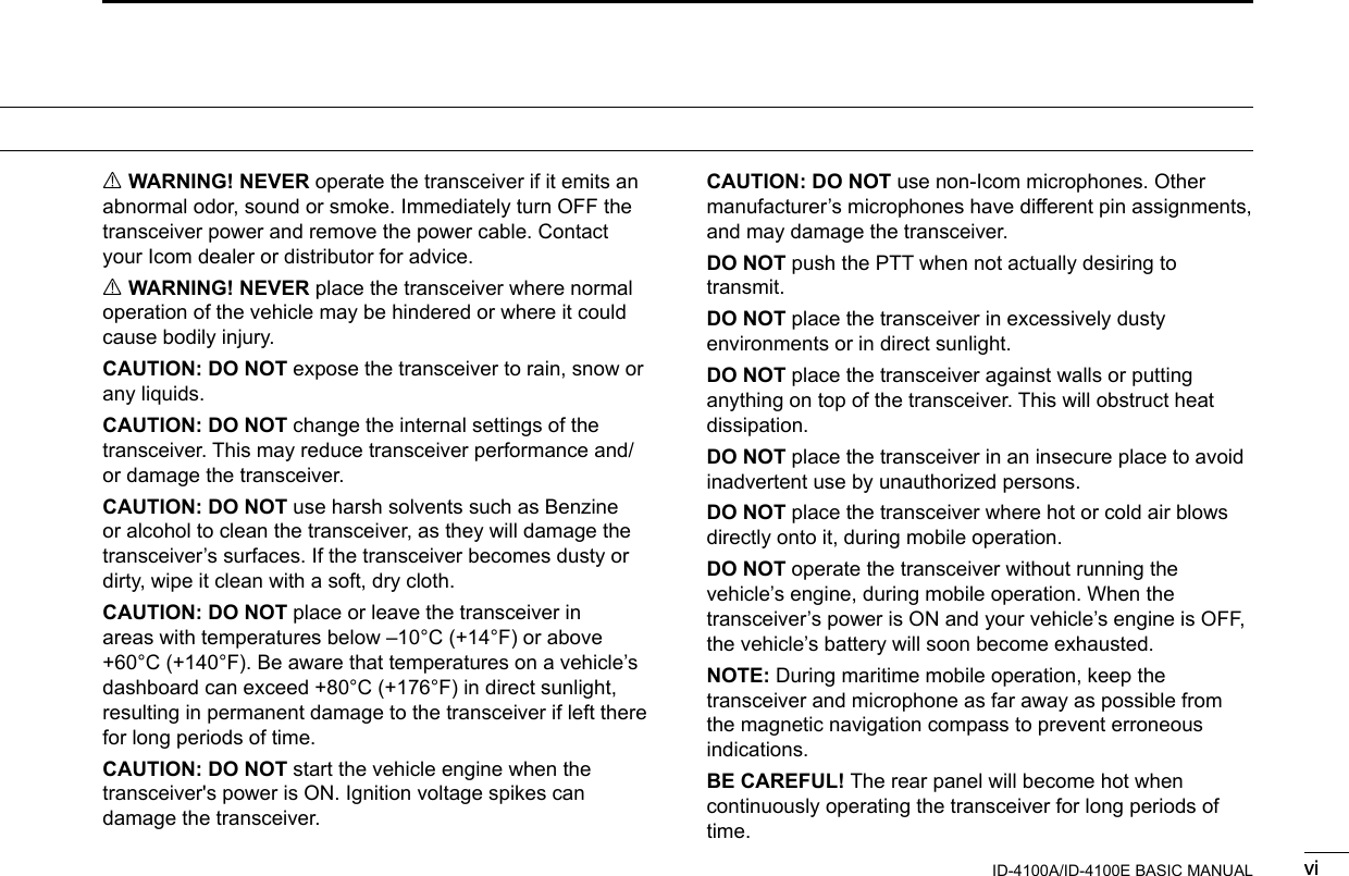
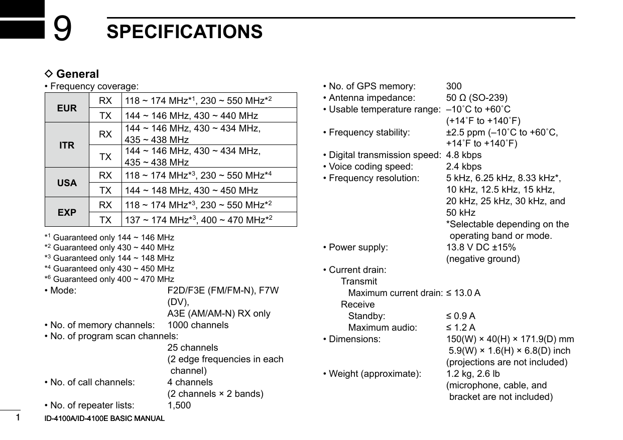
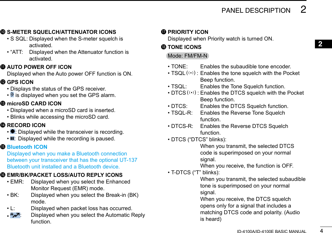
 • Push to display the MENU screen. • Hold down for 1 second to turn the Lock function ON or OFF.2CLEAR • DR KEY [](DR) • Push to toggle between “TO” and “FROM” on the DR screen. • Push to go back a tree level of the MENU screen. • Hold down for 1 second to display the DR screen.3TUNING DIAL [DIAL] • Selects an operating frequency. • Selects an option of “TO” or “FROM” on the DR screen. • Selects a Menu or Quick Menu item. • Selects an option of the Menu or Quick Menu item. • Selects a character in the Character Entry mode.4BAND/BANK • ENTER • SCAN KEY [BAND/BANK] [ï](SCAN) • In the VFO mode, push to enter the Band Select mode. • In the Memory mode, push to open the Bank Select window. • Push to set a Menu or Quick Menu item option. • Hold down for 1 second to open the Scan Type Select window. • Hold down for 3 seconds to start the last selected scan.5VFO/MEMORY • CALL KEY [V/M](CALL) • Push to toggle between the VFO and Memory modes. • In the Call channel mode, push to cancel the mode. • Hold down for 1 second to enter the Call channel mode.6MODE KEY [MODE] Push to select an operating mode.qwer t y u i o !0 !1 !2!3Display (p. ??)](https://usermanual.wiki/ICOM-orporated/386600/User-Guide-3347457-Page-22.png)
![22PANEL DESCRIPTIONNew20012ID-4100A/ID-4100E BASIC MANUALNew20017MEMORY WRITE KEY [MW] • Push to open the Memory Write window. • Hold down for 1 second to save the operating data into a blank channel. • While the scan is paused, hold down for 1 second to set the frequency as a skip channel.8RX CALL SIGN CAPTURE KEY [RX→CS] • Push to display the RX>CS screen. • Hold down for 1 second to set the received station call sign as the destination (UR) call sign.9MONITOR KEY [MONI] Push to turn the Monitor function ON or OFF.QUICK MENU • MUTE KEY [QUICK] (MUTE) • Push to open the Quick Menu window. • Hold down for 1 second to turn the Mute function ON or OFF.SQUELCH CONTROL [SQL] Adjusts the squelch level. L Normally, set the squelch level to where noise and the “BUSY” icon just disappear. (closed) L The RF attenuator activates and increases the attenuation when rotated clockwise at beyond the center position.POWER • SPEECH KEY [ ](SPCH) • Push to audibly announce the displayed frequency, operating mode or call sign. • Hold down for 1 second to turn the transceiver ON or OFF.MICROPHONE CONNECTOR (p. ??) Connects the supplied or an optional microphone.VOLUME CONTROL [VOL] Adjusts the audio volume level.](https://usermanual.wiki/ICOM-orporated/386600/User-Guide-3347457-Page-23.png)
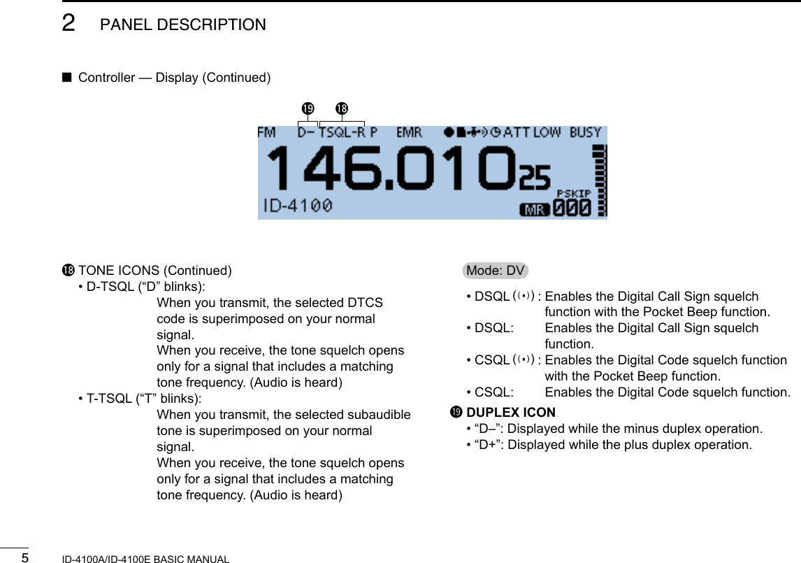
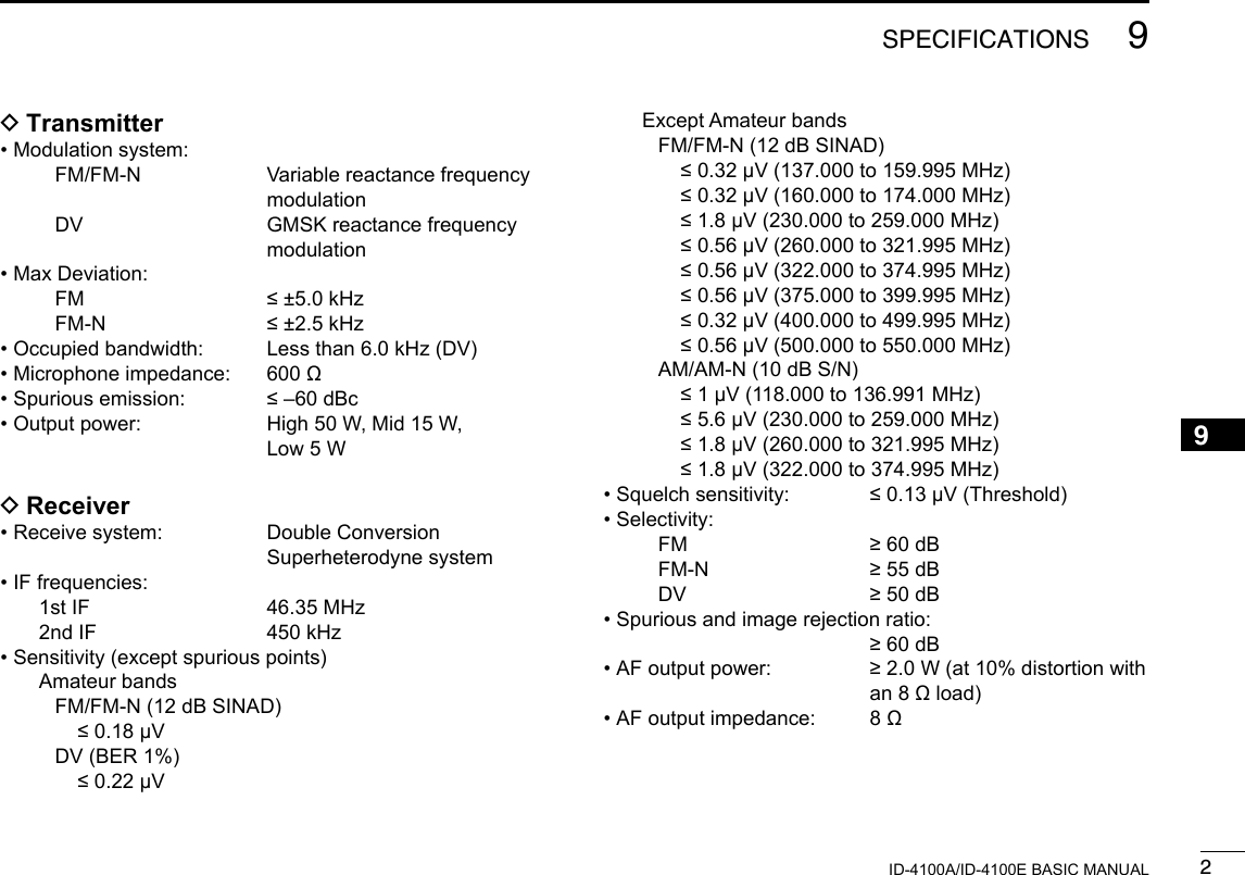
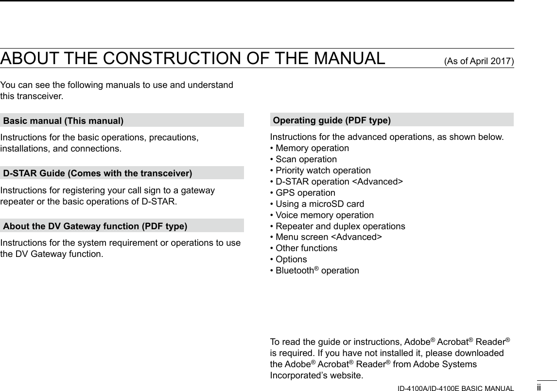
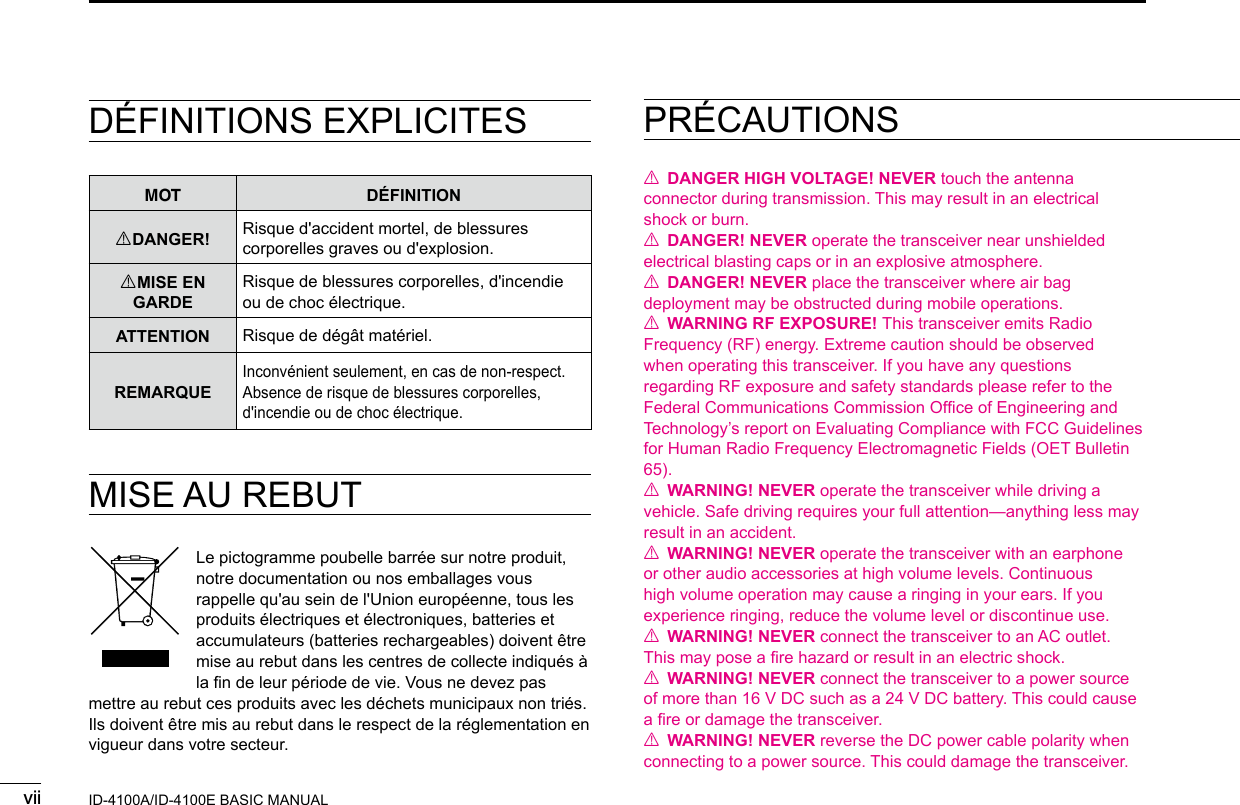
![62PANEL DESCRIPTIONNew20012ID-4100A/ID-4100E BASIC MANUAL ■Main unit — Front panel1microSD CARD SLOT [micro SD] Insert a microSD card (user supplied).2CONTROLLER CONNECTOR Connect to the controller using the supplied control cable.3MICROPHONE CONNECTOR Plug in the supplied or optional microphone. DMicrophone connector information12345678Front panel viewPINNo.NAME DESCRIPTION SPECIFICATIONS1 8 V +8 V DC output Maximum 10 mA2MIC U/D Frequency Up/DownUP: GroundDN: Ground through 470 ˘3M8V SW Grounds when the HM-207 is connected —4 PTT PTT input Ground for transmission5MIC E Microphone ground —6 MIC Microphone input —7GND PTT ground —8DATA INWhen the HM-207 is connected, inputs HM-207 data—q w e](https://usermanual.wiki/ICOM-orporated/386600/User-Guide-3347457-Page-27.png)
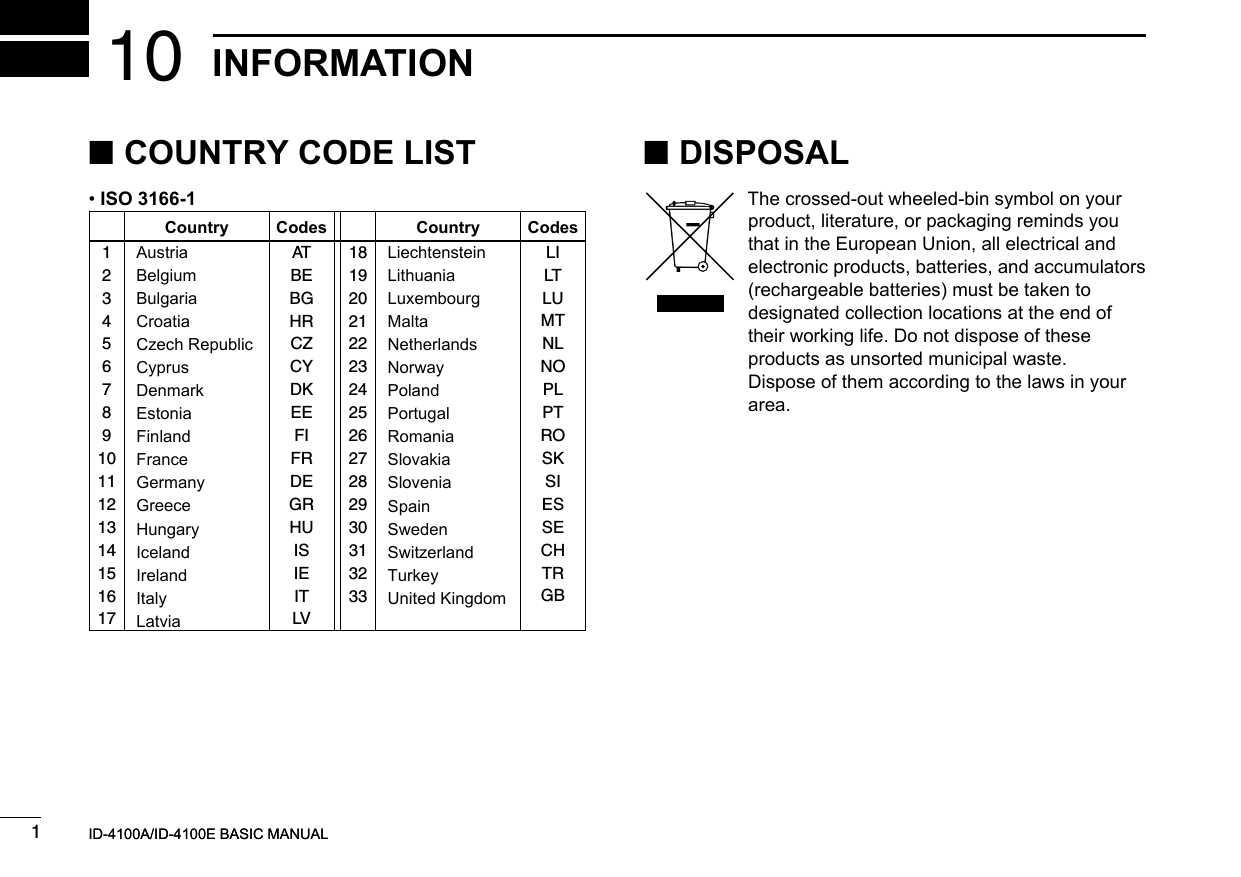
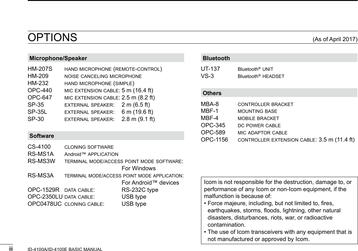
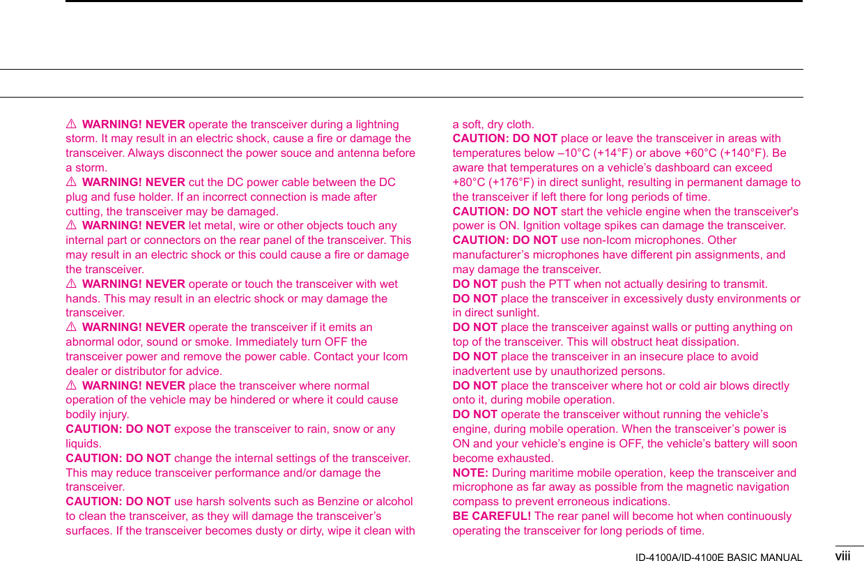
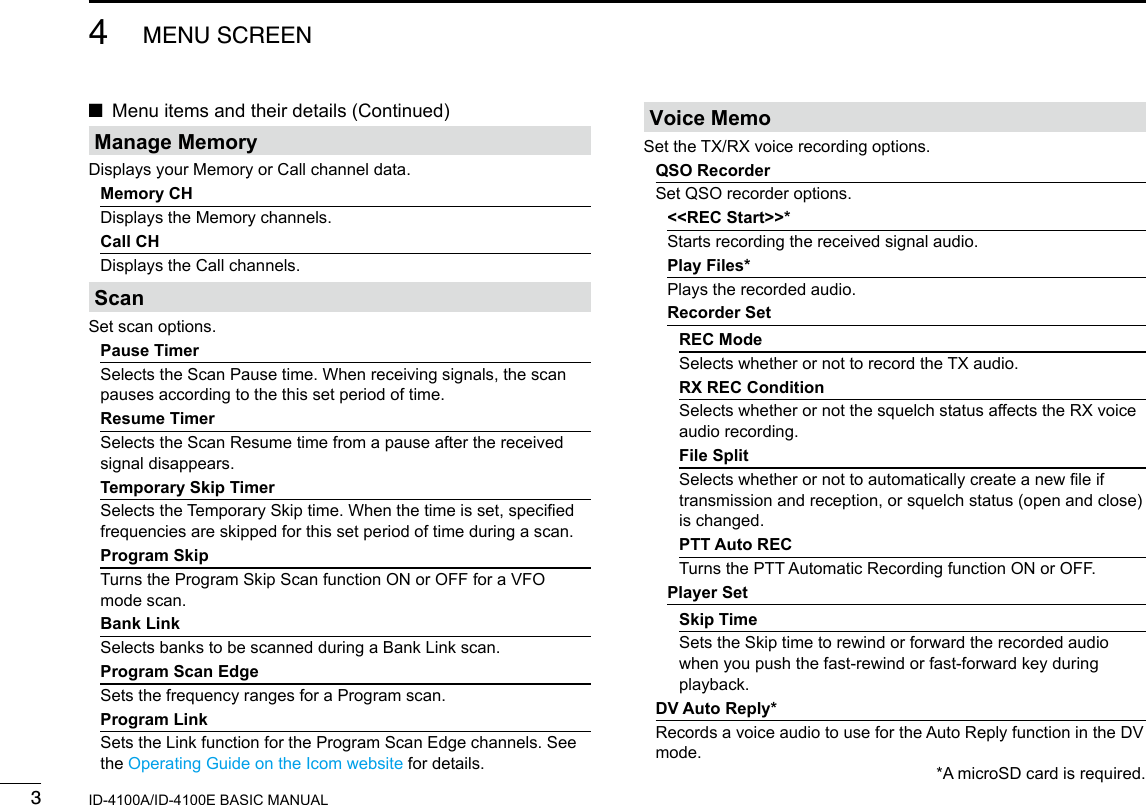
![72PANEL DESCRIPTIONNew2001 New2001ID-4100A/ID-4100E BASIC MANUAL ■Main unit — Rear panel1ANTENNA CONNECTOR Connect a 50 Ω impedance antenna with a PL-259 connector. L The transceiver has a built-in duplexer, so you can use a 144 and 430 MHz dual-band antenna without needing an external duplexer.2COOLING FAN The cooling fan for heat dissipation. L You can select the Fan control option in the MENU screen, and automatically start to rotate when you begin transmitting, or continuously rotate from power ON.3DATA JACK [DATA] Connect a PC through the optional data communication cable, for cloning or data communication in the DV mode.4EXTERNAL SPEAKER JACK Connect to an 8 Ω external speaker.5DC POWER SOCKET [DC 13.8V] Connect a 13.8 V DC power source through the supplied DC power cable.q w e rt](https://usermanual.wiki/ICOM-orporated/386600/User-Guide-3347457-Page-28.png)
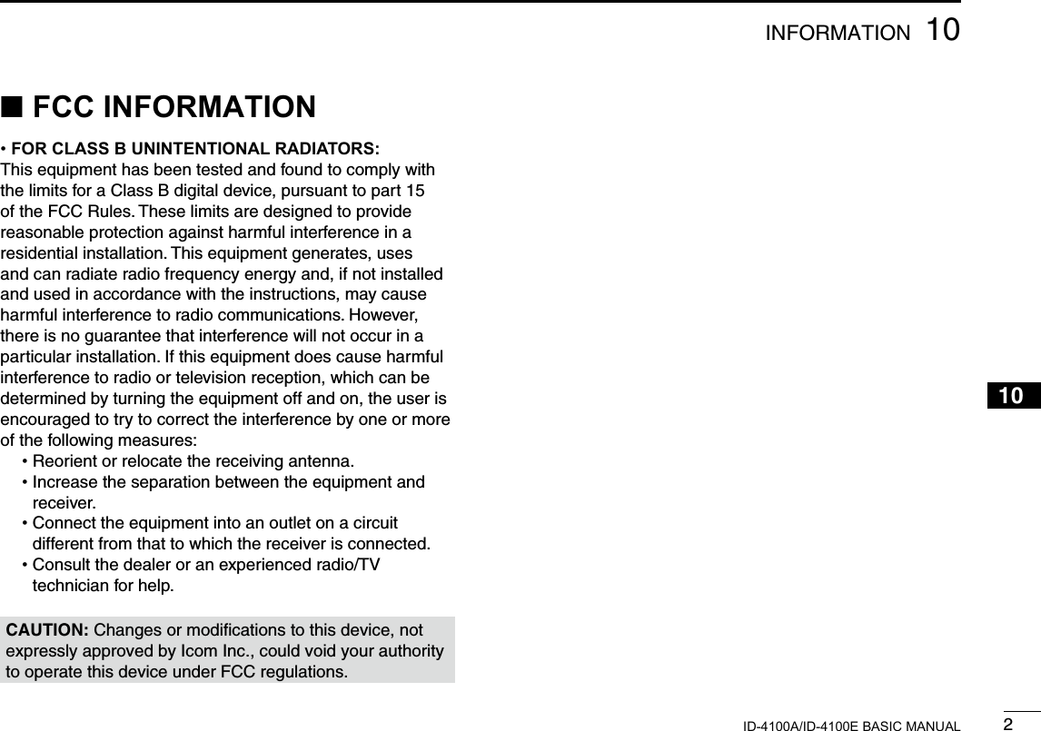
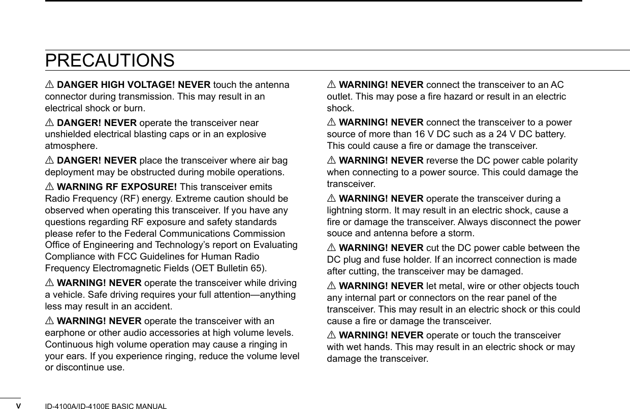
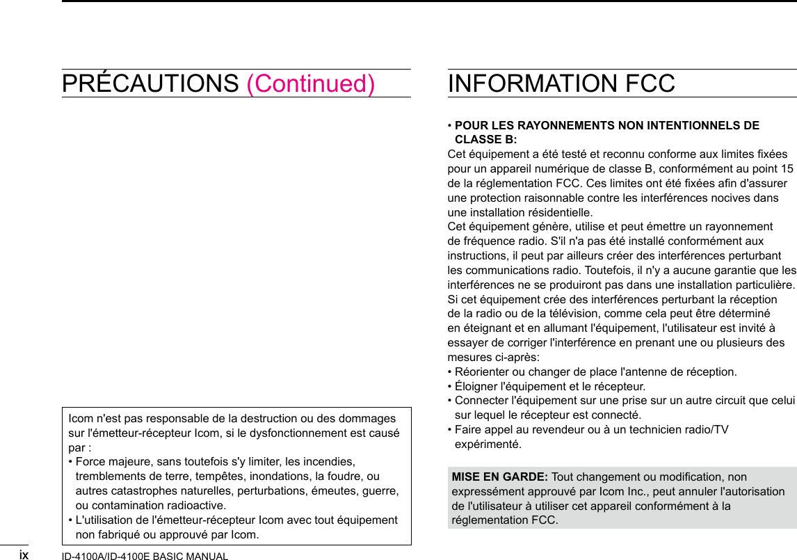
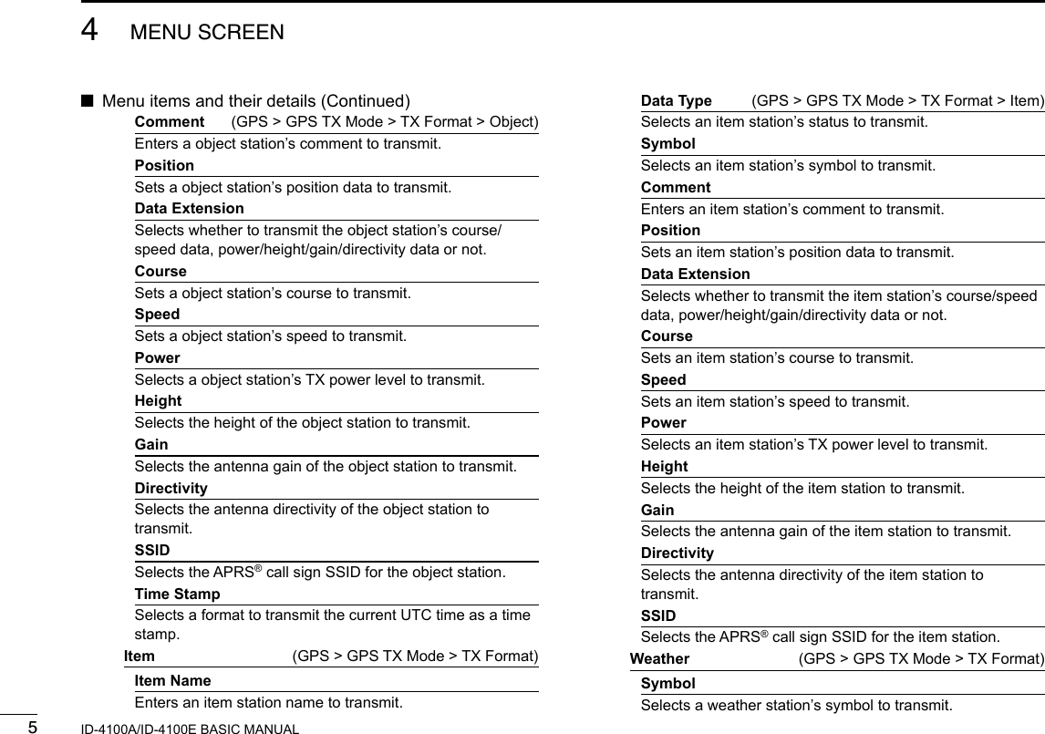
![82PANEL DESCRIPTIONNew20012ID-4100A/ID-4100E BASIC MANUAL ■Microphone (HM-207S)With the HM-207S, you can input numbers for frequency or Memory channel setting, and easily adjust the audio volume or squelch level.qwe!0tyiuor!7Mic element!6!1!2!3!4!51LED 1 Lights red while holding down [PTT].2[∫]/[√] (UP/DOWN) KEYS • Push to change the operating frequency or Memory channel. • Hold down to continuously change the frequency or Memory channel.3[PTT] SWITCH Hold down to transmit, release to receive.4[VFO/MR• ] KEY • Push to toggle between the VFO and Memory modes. • Hold down for 1 second to turn the Lock function ON or OFF.5[HOME/CALL] KEY • Push to select the Home channel. • Hold down for 1 second to enter or cancel the Call channel mode.6[BAND] KEY Push to select the operating bands.7[F-1] KEY Push to activate the preset function of the [F-1] key. (Default: During RX/Standby: [MODE] During TX: [T-CALL]) [F-2] KEY Push to activate the preset function of the [F-2] key. (Default: During RX/Standby: [Monitor] During TX: [---])TIP: You can assign a desired function in the MENU screen.](https://usermanual.wiki/ICOM-orporated/386600/User-Guide-3347457-Page-29.png)
![92PANEL DESCRIPTIONNew2001 New2001ID-4100A/ID-4100E BASIC MANUAL[VOL√/B] KEY • Push to decrease the audio output level. • In the DTMF Code Entry mode, push to input ‘B.’[SQL∫/C] KEY • Push to increase the squelch level. • In the DTMF Code Entry mode, push to input ‘C.’[SQL√/D] KEY • Push to decrease the squelch level. • In the DTMF Code Entry mode, push to input ‘D.’[#/CE] KEY • In the Frequency Entry mode, push to delete a number. • In the DTMF Code Entry mode, push to input ‘#.’[M/.] KEY • In the Frequency Entry mode, push to input a ‘.’ (decimal point). • In the DTMF Code Entry mode, push to input ‘M.’[0] to [9] KEYS In the Frequency or DTMF Code Entry mode, push to input ‘0’ through ‘9.’qwe!0tyiuor!7Mic element!6!1!2!3!4!5 ■Microphone (HM-207) (Continued)8[CLR] KEY Push to cancel the MENU screen or Quick Menu window, then return to the standby screen.9[ENT] KEY • In the VFO mode, push to enter the Frequency Entry mode. • In the Memory mode, push to enter the Memory Channel Number Entry mode. • After entering the number, push to set.LED 2 Lights green when transceiver’s power is ON.[VOL∫/A] KEY • Push to increase the audio output level. • In the DTMF Code Entry mode, push to input ‘A.’](https://usermanual.wiki/ICOM-orporated/386600/User-Guide-3347457-Page-30.png)
![102PANEL DESCRIPTIONNew20012ID-4100A/ID-4100E BASIC MANUAL DSetting frequency and Memory channelExample of frequency setting: zFirst, push [VFO/MR] to select the VFO mode.To enter the frequency 435.680 MHz: zPush [4], [3], [5], [6], [8], [0], then [ENT].To change 435.680 MHz to 435.540 MHz: zPush [•], [5], [4], [0], then [ENT].To enter the 433.000 MHz frequency: zPush [4], [3], [3], then [ENT].Example of Memory channel setting: zFirst, push [VFO/MR] to select the Memory mode.To select the Memory channel ‘5’: zPush [5] then [ENT].](https://usermanual.wiki/ICOM-orporated/386600/User-Guide-3347457-Page-31.png)
![New20011New2001New2001BASIC OPERATION3ID-4100A/ID-4100E BASIC MANUALID-4100A/ID-4100E BASIC MANUAL ■Turning ON the powerHold down [ ] for 1 second to turn ON the power. • A beep sounds. • After the opening message and power source voltage are displayed, the operating frequency or repeater name is displayed. LHold down [ ] for 1 second again to turn OFF the power. ■ Setting audio volume and squelch level1. Rotate [VOL] to adjust the audio level.2. Rotate [SQL] until the noise and “BUSY” just disappear. ■Monitor functionThe Monitor function is used to listen to weak signals without disturbing the squelch setting.Push [MONI] to open or close the squelch. • “BUSY” blinks and audio is heard when the squelch is open. • Rotating [SQL] clockwise makes the squelch tight. Tight squelch is for strong signals. • When rotating [SQL] clockwise beyond the center position, [SQL] can be used as ‘S-meter Squelch’ or ‘Attenuator.’ Select the [SQL] option in the MENU screen. (p. ??) (MENU > Function > Squelch/ATT Select)[VOL][SQL][ ][MONI]](https://usermanual.wiki/ICOM-orporated/386600/User-Guide-3347457-Page-32.png)
![23BASIC OPERATIONNew20013ID-4100A/ID-4100E BASIC MANUALNew2001 ■Quick Menu windowIn the Quick Menu window, the selectable items differ, depending on the operating mode or function. The items listed below are examples. DQuick Menu window operation[DIAL]Selects an item or option.[QUICK]Toggles between Quick Menu window and the standby screen.[ï] • Sets an option. • Goes to a next tree level.Simplied description—‘Select’ operationIn this manual, user‘s ‘Select’ operation is simplied.Simplied description:1. Push [QUICK].2. Select “TX Power,” then push [ï].Operation:1. Push [QUICK] to open the Quick Menu window.2. Rotate [DIAL] to select “TX Power,” then push [ï].VFO mode Memory mode Call CH mode DR functionBand Select Bank Select TX Power Group SelectTX Power TX Power DUP Repeater DetailDUP DUP TONE TX PowerTONE TONE TS DTMF TXMHz TS DTMF TX Voice TXTS SKIP Voice TX RX HistoryDTMF TX DTMF TXGPS Information GPS InformationVoice TX Voice TX GPS Position GPS PositionGPS Information GPS InformationWeather Information*1Weather Information*1GPS Position GPS PositionTemporary Skip*2Temporary Skip*2Weather Information*1Weather Information*1PRIO Watch PRIO WatchTemporary Skip*2Temporary Skip*2Weather CH*3Weather CH*3PRIO Watch PRIO Watch Weather Alert*3Weather Alert*3Weather CH*3Weather CH*3Display Type Home CH SetWeather Alert*3Weather Alert*3Clock DSQLHome CH Set Home CH Set Voltage SKIPClock Display Type Band Scope ClockVoltage Clock <<REC Start>> VoltageBand Scope Voltage <<REC Start>><<REC Start>> Band Scope<<REC Start>>*1 Displayed when the D-PRS TX format is set to “Weather.”*2 Displayed while scanning.*3 Displayed in only the USA version transceivers](https://usermanual.wiki/ICOM-orporated/386600/User-Guide-3347457-Page-33.png)
![33BASIC OPERATIONNew2001 New2001ID-4100A/ID-4100E BASIC MANUAL ■Selecting the Mode DVFO modeYou use the VFO mode to set the operating frequency. DMemory modeYou use the Memory mode to operate on Memory channels. DCall channel modeYou use the Call channel mode to operate on the Call channels.1. Push [V/M] several times until you enter the VFO or Memory mode. • In the Memory mode, and the selected Memory channel number are displayed. InformationL • Pushing [V/M] toggles between the VFO and Memory modes. • To enter the Call channel mode, hold down [V/M](CALL) for 1 second. • In the Call channel mode, “144 C0,” “144 C1,” “430 C0,” or “433 C1” is displayed. • In the Call channel mode, push [V/M](CALL) to cancel the mode.2. Rotate [DIAL] to select an operating frequency or a channel. D Weather channel mode (Selectable in only the USA version transceivers)You can use the Weather channel mode to hear weather broadcasts from the NOAA (National Oceanographic and Atmospheric Administration) broadcasts.1. Push [QUICK].2. Rotate [DIAL] to select “WX CH,” then push [ï]. • The selected weather channel number (“WX-01” to “WX-10”) is displayed. L To cancel the mode, select “WX CH OFF” in the Quick Menu window.[QUICK][V/M](CALL)[DIAL][ï]](https://usermanual.wiki/ICOM-orporated/386600/User-Guide-3347457-Page-34.png)
![43BASIC OPERATIONNew20013ID-4100A/ID-4100E BASIC MANUAL ■Selecting the operating bandThe transceiver can receive on the AIR, 144 MHz, 230 MHz, 300 MHz, and 430 MHz bands.You can transmit on only the amateur band frequencies.1. Push [V/M] several times until you enter the VFO mode.2. Push [BAND]. • Enters the Band Select mode. 3. Rotate [DIAL] to select an operating band.4. Push [ï]. • Sets the band, then returns to the standby screen. ■Selecting the operating modeThe transceiver has a total of 5 operating modes, AM, AM-N, FM, FM-N, and DV. (Default: FM)By pushing [MODE], you can select an operating mode. InformationL • You can select the AM mode for only the AIR, 230 MHz, and 300 MHz bands. • You can select the AM-N mode for only the AIR band. • You can select the FM, FM-N, or DV modes for only the 144 MHz, 230 MHz, 300 MHz, and 430 MHz bands. • While in the FM-N mode, the TX modulation is automatically set to narrow (approximately ±2.5 kHz) • When you set the “GPS TX Mode” item to “D-PRS” or “NMEA,” is displayed besides the mode icon. (See the Operating Guide on the Icom website for details.)TIP: You can select the operating band in the Quick Menu window.1. Push [QUICK].2. Rotate [DIAL] to select “Band Select,” then push [ï].3. Select an operating band, then push [ï].[MODE][V/M][DIAL][BAND]/[ï]](https://usermanual.wiki/ICOM-orporated/386600/User-Guide-3347457-Page-35.png)
![53BASIC OPERATIONNew2001 New2001ID-4100A/ID-4100E BASIC MANUAL ■Setting a frequency DSelecting a tuning stepIf you select the operating frequency by rotating [DIAL] in the VFO mode, the frequency changes in the selected tuning step. L The VFO mode scan and the Band Scope function also use this step to search for a signal.1. Push [QUICK].2. Rotate [DIAL] to select “TS,” then push [ï].3. Select a tuning step, then push [ï]. Options (kHz):5.0 6.25 8.33* 10.0 12.5 1520 25 30 50 Auto* *Selectable only in the AIR band mode. • Sets the tuning step, then returns to the standby screen. L You can set the tuning step for both the VFO and Memory mode. LYou can set the tuning step for each band. DSelecting the 1 MHz tuningYou can change the operating frequency in ‘MHz’ steps for quick tuning.1. Push [QUICK].2. Rotate [DIAL] to select “MHz,” then push [ï]. • Enters the 1 MHz Tuning Select mode. 3. Rotate [DIAL]. • The frequency changes in 1 MHz steps.4. Push [ï]. • Sets the frequency, then returns to the standby screen.[QUICK][DIAL][ï]](https://usermanual.wiki/ICOM-orporated/386600/User-Guide-3347457-Page-36.png)
![63BASIC OPERATIONNew20013ID-4100A/ID-4100E BASIC MANUAL ■Lock functionYou can use the Lock function to prevent accidental frequency changes and unnecessary function access.Hold down [ ] for 1 second to turn the Lock function ON or OFF. • “LOCk ON” or “LOCk OFF” is briey displayed when the Lock function is turned ON or OFF. L When the Lock function is ON and you operate the transceiver, “LOCK” is displayed. L You can still use [ ], [PTT], [SQL], [VOL] and [MONI], even if the Lock function is ON. ■ DR functionThe DR (D-STAR Repeater) function is for D-STAR repeater operation. This function enables you to easily select the preset repeaters and UR call signs by rotating [DIAL].See the D-STAR guide comes with transceiver for details.1. Hold down [DR] for 1 second. • Displays the DR screen.2. Push [DR] several times until you select “FROM.” 3. Rotate [DIAL] to select an access repeater.4. Push [DR]. • Cancels the DR screen.[DR][ ][DIAL]](https://usermanual.wiki/ICOM-orporated/386600/User-Guide-3347457-Page-37.png)
![73BASIC OPERATIONNew2001 New2001ID-4100A/ID-4100E BASIC MANUAL ■Home Channel functionYou can set the often-used frequency, Memory channel, or repeater as the Home channel in each mode (VFO/Memory/DR). The Home channels are selectable by pushing [HOME] on the microphone in each mode. L To select the Home channel by pushing [HOME], the Home CH key function must be assigned into an [F-1] or [F-2] key. See the Operating Guide on the Icom website for details. DSetting a Home channel1. Select the VFO or Memory mode, or the DR screen to set a Home channel. (pp. ??, ??)2. Select a frequency, Memory channel, or an access repeater to be set as a Home channel. (pp. ??, ??)3. Push [QUICK].4. Rotate [DIAL] to select “Home CH Set,” then push [ï].5. Select “Set Frequency” (VFO mode), “Set Channel” (Memory mode), or “Set Repeater” (DR screen), then push [ï]. • Sets a Home channel, then returns to the standby screen. ■Speech functionThe Speech function audibly announces information after pushing [SPCH]. Also, you can set various Speech functions, such as the DIAL Speech function or Mode Speech function on the MENU screen. (p. ??) InformationL • In the VFO, Memory, or Call channel mode, the Speech function announces the displayed frequency and operating mode. • On the DR screen, the Speech function announces the displayed call sign. • When you push [SPCH] while recording the received audio in the DV mode, the received audio will be muted, and no audio is recorded onto the SD card. In modes other than the DV mode, the received audio will be recorded.One, four, six, point,zero, one, megahertz, FM.[SPCH]](https://usermanual.wiki/ICOM-orporated/386600/User-Guide-3347457-Page-38.png)
![83BASIC OPERATIONNew20013ID-4100A/ID-4100E BASIC MANUAL ■Transmitting DTransmitting on an Amateur bandBefore transmitting, monitor the operating frequency to make sure transmitting won’t cause interference to other stations on the same frequency.CAUTION: DO NOT transmit without an antenna. This may damage the transceiver.NOTE: You can transmit on only the amateur band frequencies.1. Set the operating frequency. (p. ??)2. Push [QUICK].3. Rotate [DIAL] to select “TX Power,” then push [ï]. • Opens the TX Power Select window.4. Select the transmit output power level, then push [ï]. LSelect a level to suit your operating requirements. LWhen you select high power, the power icon disappears.5. Hold down [PTT] to transmit, and speak at your normal voice level. • is displayed while transmitting. • The S/RF meter displays the output power level. 6. Release [PTT] to receive. [QUICK][DIAL][ï]](https://usermanual.wiki/ICOM-orporated/386600/User-Guide-3347457-Page-39.png)
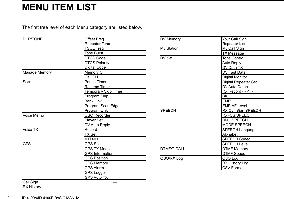
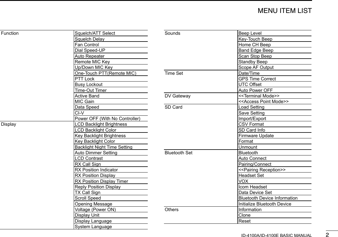
![New20011New2001New2001MENU SCREEN4ID-4100A/ID-4100E BASIC MANUALID-4100A/ID-4100E BASIC MANUAL ■MENU screen descriptionThe MENU screen is displayed after pushing [MENU].You can use the MENU screen to set infrequently changed values or function settings.See the following pages for details of each set screen.TIP: The MENU screen is constructed in a tree structure. You may go to the next tree level, or go back a level, depending on the selected item.DUP/TONE... p. ??Manage Memory p. ??Scan p. ??Voice Memo p. ??Voice TX p. ??GPS p. ??Call Sign p. ??RX History p. ??DV Memory p. ??My Station p. ??DV Set p. ??SPEECH p. ??DTMF/T-CALL p. ??QSO/RX Log p. ??Function p. ??Display p. ??Sounds p. ??Time Set p. ??DV Gateway p. ??SD Card p. ??Bluetooth Set p. ??Others p. ?? ■Selecting a MENU item DMENU screen operation[MENU]Switches between the MENU screen and the standby screen.[DIAL]Selects an item or option.[QUICK]Returns to the default setting.[]Goes back the tree level.[ï] • Sets an option. • Goes to the next tree level.Simplied description—‘Select’ operationIn this manual, user‘s ‘Select’ operation is simplied as shown below.Simplied description:Select “30min.”Operation:Rotate [DIAL] to select “30min.”](https://usermanual.wiki/ICOM-orporated/386600/User-Guide-3347457-Page-40.png)
![24MENU SCREENNew20014ID-4100A/ID-4100E BASIC MANUALNew2001TIP: To return to the default setting:1. Push [QUICK] in step 4. 2. Select “Default,” then push [ï]. DSelecting a Menu itemExample: Set the “Auto Power OFF” item to “30 min.”Time Set > Auto Power OFF1. Push [MENU].2. Rotate [DIAL] to select “Time Set,” then push [ï].3. Select “Auto Power OFF,” then push [ï].4. Select “30min,” then push [ï]. • Sets the option, then goes back a tree level. (TIME SET screen is displayed.)5. Push [MENU]. • Returns to the standby screen. ■Menu items and their detailsThis topic describes the Menu items and their details. DUP/TONE...Settings to access repeaters.Offset FreqSets the frequency offset for duplex (repeater) operation.Repeater ToneSelects a tone frequency used to access the repeaters.TSQL FreqSelects a tone frequency for the Tone Squelch or the Pocket Beep function.Tone BurstTurns the Tone Burst function ON or OFF. This function is used to suppress the squelch tail noise of FM mode on the RX side, if you transmit a signal which superimposes the CTCSS tone or subaudible tone.DTCS CodeSelects a DTCS (both encoder/decoder) code for DTCS Squelch or the Pocket Beep function.DTCS PolaritySelects the DTCS polarity for the DTCS Squelch or the Pocket Beep function.Digital CodeSelects a digital code for the Digital Code Squelch function.](https://usermanual.wiki/ICOM-orporated/386600/User-Guide-3347457-Page-41.png)
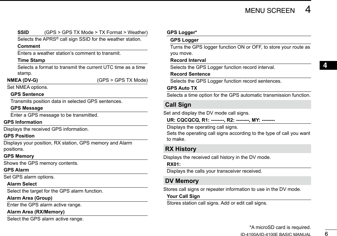
![44MENU SCREENNew20014ID-4100A/ID-4100E BASIC MANUALVoice TXSet microphone voice recording options.Record*Starts recording the microphone audio.TX SetRepeat TimeSets the repeat interval. The transceiver repeatedly transmits the recorded voice audio at this interval.TX MonitorThe TX Monitor function outputs the TX voice audio from the speaker during voice transmission.<<TX>>*The transceiver transmits the recorded voice audio.GPSSet GPS options.GPS SetGPS SelectSelects either the internal or an external GPS receiver that the transceiver receives its position data from.Manual PositionManually enter your current position.GPS Out (To DATA jack)Turns the output of GPS information from the internal GPS receiver to the [DATA] jack ON or OFF.GPS TX ModeSet the GPS TX mode.OFFTurns OFF the GPS TX function.D-PRS (DV-A) (GPS > GPS TX Mode)Set D-PRS options.Unproto AddressEnters an unproto address, or keeps the default.TX FormatPositionSymbolSelects a desired D-PRS Symbol to transmit.SSIDSelects the APRS® call sign SSID.CommentEnters a comment to transmit.Time StampSelects the format to transmit the current UTC time as a time stamp.AltitudeTurns the altitude transmit option ON or OFF.Data ExtensionSelects whether or not to transmit the course/speed, power/height/gain/directivity data.Object (GPS > GPS TX Mode > TX Format)Object NameEnters a object station name to transmit.Data TypeSelects a object station’s status to transmit.SymbolSelects a object station’s symbol to transmit.*A microSD card is required.](https://usermanual.wiki/ICOM-orporated/386600/User-Guide-3347457-Page-43.png)
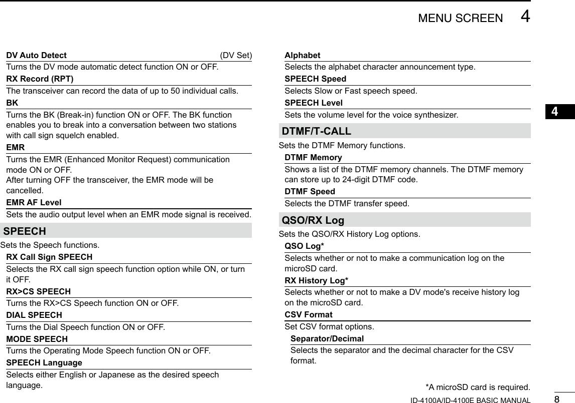
![74MENU SCREENNew2001 New2001ID-4100A/ID-4100E BASIC MANUALRepeater ListStores repeater information. Add or edit repeater information.( See the Operating Guide on the Icom website for details of the preloaded data.) NOTE: The repeater list described in this manual may differ from your preloaded list.My StationSets and stores MY call sign to use in the DV mode.My Call SignStores MY call signs. Select or edit a MY call sign to use in the DV mode.TX MessageStores TX Messages.Select or edit TX Message to use in the DV mode.DV SetSets values for the DV mode operations.Tone ControlSet the received audio tones.RX BassSets the DV mode received audio bass lter level to Cut, Normal or Boost.RX TrebleSets the DV mode received audio treble lter level to Cut, Normal or Boost.RX Bass BoostTurns the DV mode received audio Bass Boost function ON or OFFTX Bass (DV Set > Tone Control)Sets the DV mode transmit audio bass lter level to Cut, Normal or Boost.TX TrebleSets the DV mode transmit audio treble lter level to Cut, Normal or Boost.Auto ReplySelects the Automatic Reply function.DV Data TXSelects manually or automatically to transmit data.DV Fast DataThe DV Fast data mode sends data through both the audio and data frames in the DV mode. The data speed of the DV Fast data mode (approximately 3480 bps) is 3.5 times faster than the low-speed data communication mode (approximately 950 bps). In the DV Fast data mode, no audio can be sent.Fast DataSelects whether or not to use DV Fast data mode for data communication in the DV mode.GPS Data SpeedSet the GPS data transmission speed in the DV Fast data mode. TX Delay (PTT)Set the TX delay time after releasing [PTT] when the “DV Data TX” is set to “PTT” and data is sent in the DV Fast data mode. Digital MonitorSelects the DV mode RX monitoring when [SQL] is held down.Digital Repeater SetTurns the digital repeater setting function ON or OFF. This function is usable in any DV mode except when using the DR function. ■Menu items and their details (Continued)](https://usermanual.wiki/ICOM-orporated/386600/User-Guide-3347457-Page-46.png)
![94MENU SCREENNew2001 New2001ID-4100A/ID-4100E BASIC MANUALDate (QSO/RX Log > CSV Format)Selects the date format.FunctionSets various function’s options.Squelch/ATT SelectSelects to use the S-Meter Squelch or the Attenuator function for the [SQL] control.Squelch DelaySelects to shorten or lengthen the time until the squelch opens.Fan ControlSelects the cooling fan control condition.Dial Speed-UPTurns the dial speed acceleration ON or OFF.Auto Repeater*Turns the Auto Repeater function ON or OFF.Remote MIC KeySelects the key function for [F-1] or [F-2] on the supplied remote-control microphone.During RX/StandbySelects the key function to be used while receiving or in the standby mode.During TXSelects the key function to be used while transmitting.Up/Down MIC KeySelects the key function for [UP] or [DN] on the optional hand microphone.During RX/Standby (Function > Up/Down MIC Key)Selects the key function to be used while receiving or in the standby mode.During TXSelects the key function to be used while transmitting.One-Touch PTT(Remote MIC)Turns the One-Touch PTT function ON or OFF.PTT LockTurns the PTT Lock function ON or OFF.Busy LockoutTurns the Busy Lockout function ON or OFF.Time-Out TimerSelects the Time-Out Timer time options. Active BandEnables continuous frequency selection across all bands by rotating [DIAL].MIC GainSets the microphone sensitivity to suit your preference.Data SpeedSelects the data transmission speed for low-speed communication, or between the [DATA] jack and external modules like a GPS receiver, and so on.CI-VSet CI-V options.CI-V AddressSets the transceiver’s unique CI-V hexadecimal address code.CI-V Baud RateSets the CI-V code transfer speed. ■Menu items and their details (Continued)*Does not appear, depending on the transceiver version.](https://usermanual.wiki/ICOM-orporated/386600/User-Guide-3347457-Page-48.png)
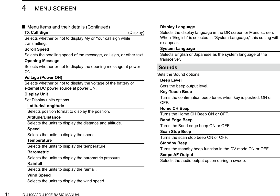
![104MENU SCREENNew20014ID-4100A/ID-4100E BASIC MANUALCI-V Transceive (Function > CI-V)Turns the CI-V Transceive function ON or OFF.CI-V Bluetooth→REMOTE Transceive AddressSets the address to inhibit the external control with CI-V for the transceiver through the [SP2] (REMOTE) jack.Power OFF (With No Controller)Selects whether or not to automatically turn OFF the transceiver when the controller is disconnected from the transceiver.DisplaySets the Display options.LCD Backlight BrightnessSelects the LCD backlight brightness level.LCD Backlight ColorSelects the LCD backlight color.Key Backlight BrightnessSelects the key backlight brightness level.Key Backlight ColorSelects the key backlight color.Backlight Night Time SettingNight Time SettingSelects whether or not to turn down the backlight brightness for nighttime operation.BrightnessSelects the backlight brightness level for nighttime operation.Night Time StartSets the start time for nighttime operation.Night Time EndSets the end time for nighttime operation.Auto Dimmer SettingAuto DimmerSets the Auto Dimmer function for nighttime operation.Auto Dimmer TimerSets the time period until the backlight turns OFF when the “Auto Dimmer” item is set to “Auto-OFF” or “Auto-1” to “Auto-3.”Auto Dimmer Cancel (PTT)Selects the transceiver operation when [PTT] is pushed while the Auto Dimmer is activated.Auto Dimmer Cancel (DV RX)Selects the transceiver operation when receiving a DV signal while the Auto Dimmer is activated.LCD ContrastSets the contrast level of the LCD.RX Call SignSelects the call sign and message display option when receiving a call.RX Position IndicatorSelects whether or not to display the indicator when the position data is included in the signal received in the DV mode.RX Position DisplaySelects whether or not to display the caller’s position data in a dialog when the data is included in the signal received in the DV mode.RX Position Display TimerSets the RX position data display time period.Reply Position DisplaySelects whether or not to display the caller’s position data in a dialog when the data is included in the Auto Reply signal.](https://usermanual.wiki/ICOM-orporated/386600/User-Guide-3347457-Page-49.png)
![134MENU SCREENNew2001 New2001ID-4100A/ID-4100E BASIC MANUALBluetooth Set*Sets the Bluetooth® options.BluetoothTurns the Bluetooth function ON or OFF.Auto ConnectSelects whether or not to automatically connect to a paired Bluetooth device when the device is turned ON.Pairing/ConnectSelects to pair or connect to a Bluetooth device.Device SearchSearch HeadsetSearches for a Bluetooth headset.Search Data DeviceSearches for a Bluetooth data device.RS-MS1ISearches for an iOS device.Pairing listDisplays the paired device.<<Pairing Reception>>Accepts the connection request from a Bluetooth device.Headset SetAF OutputSelects the AF output option for when you use a Bluetooth headset.Headset Function SelectSelects the desired PTT and microphone combination when either a Bluetooth headset or the radio microphone are used.VOX (Bluetooth Set > Headset Set)VOXTurns the VOX function ON or OFF when you use a Bluetooth headset.VOX LevelSets the MIC Gain level.When the microphone input level is higher than this set value, the transceiver starts to transmit, and the input level is lower than this set value, it returns to receive.VOX DelaySets the VOX Delay time for the transmitter stays ON after you stop speaking before the VOX switches to receive.VOX Time-Out TimerSets the VOX Time-Out Timer to prevent an accidental prolonged transmission.Icom HeadsetSets to use the optional Icom Bluetooth headset (VS-3).Power SaveSets the Power save function to prolong the headset battery.One-Touch PTTSets the One-Touch PTT function to toggle between transmission and reception by pushing [PTT].PTT BeepSets to sound a beep when you push [PTT].Custom Key BeepSets to sound a beep when you push the custom key ([PLAY]/[FWD]/[RWD]).*The optional UT-137 is required. ■Menu items and their details (Continued)](https://usermanual.wiki/ICOM-orporated/386600/User-Guide-3347457-Page-52.png)
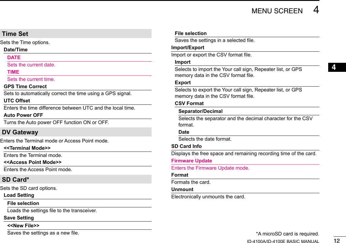
![144MENU SCREENNew20014ID-4100A/ID-4100E BASIC MANUALCustom Key (Bluetooth Set > Headset Set > Icom Headset)Selects the key function of the custom key ([PLAY]/[FWD]/[RWD]).Data Device SetSets the data device options.Serialport FunctionSelects to transmit or receive the CI-V command or the DV data.Bluetooth Device InformationShows the optional UT-137 Bluetooth unit information.Initialize Bluetooth DeviceSelects to reset the optional UT-137 Bluetooth unit.OthersSets other options.InformationVoltageShows the voltage of the external DC power source.VersionShows the transceiver’s rmware version number.CloneClone ModeReads or writes the CS-4100 data from or to the PC.ResetPartial ResetReturns all settings to their defaults, without clearing the memory contents, call sign memories or repeater lists.All ResetClears all programming and memories, and return all settings to their defaults.](https://usermanual.wiki/ICOM-orporated/386600/User-Guide-3347457-Page-53.png)
![New20011New2001New2001MEMORY OPERATION5ID-4100A/ID-4100E BASIC MANUALID-4100A/ID-4100E BASIC MANUAL ■Entering Memory channelsThe Memory mode is useful to quickly select often-used repeaters.This section describes the basic channel content entry.See the Operating Guide on the Icom website for details.Example: Entering 146.030 MHz/FM mode into a blank channel.Hold down [MW] for 1 second. • The memory contents are briey displayed, then the operating data is saved into a blank channel. ■Checking the Memory contentsYou can check the Memory contents on the MEMORY LIST screen.Example: Checking the contents of Memory channel 5.Manage Memory > Memory CH1. Push [MENU].2. Select “Manage Memory,” then push [ï].3. Select “Memory CH,” then push [ï]. • Displays the MEMORY CH screen.4. Select “ALL,” then push [ï]. • Displays the ALL screen.5. Select “005,” then push [ï]. • Displays the data in Channel 5 on the MEMORY CH (005CH) screen. LYou can select a page by rotating [DIAL].6. Push [MENU]. • Returns to the standby screen.](https://usermanual.wiki/ICOM-orporated/386600/User-Guide-3347457-Page-54.png)
![25MEMORY OPERATIONNew20015ID-4100A/ID-4100E BASIC MANUALNew2001 ■Selecting a Memory channelIn the Memory mode, you can select the Memory channels by rotating [DIAL].1. Push [V/M] several times until you enter the Memory mode. Displayed L Pushing [V/M] toggles between the VFO and Memory modes.2. Rotate [DIAL]. • Selects a Memory channel.](https://usermanual.wiki/ICOM-orporated/386600/User-Guide-3347457-Page-55.png)
![New20011New2001New2001SCAN OPERATION6ID-4100A/ID-4100E BASIC MANUALID-4100A/ID-4100E BASIC MANUAL ■VFO mode scan1. Push [V/M] several times until you enter the VFO mode.2. Hold down [BAND] for 1 second. • Opens the Scan Type Select window. L If you hold down [BAND] for 3 seconds, the last selected scan starts.3. Rotate [DIAL] to select a scan type, then push [ï]. • The scan starts. LThe decimal point and the selected scan type icon blink. L When receiving a signal, the S-meter displays the received signal strength.4. Push [BAND]. • Cancels the scan. DScan typeThe VFO mode scan has 6 scan types. • ALL: Full scan • BAND: Band scan • P-LINK0 ~ 9: Program link scan • P00 ~ 24: Program scan • DUP: Duplex scan (Displayed only when duplex is set.) • TONE: Tone scan (For the Tone Squelch scanning) L The frequencies that are set as a Skip channel (PSKIP) are skipped during a scan. (p. ??) L When the “Program Skip” item is set to “OFF,” the Skip channel frequencies are not skipped. (p. ??) (Scan > Program Skip)Scanning is a versatile function that can automatically search for signals. A scan makes it easier to locate stations to contact or listen to, or to skip unwanted channels or frequencies.This section describes the basic scan operation.See the Operating Guide on the Icom website for details.TIP: • During a scan, rotating [DIAL] switches the scanning direction. • During a scan, you can change the operating band, tuning step, and so on, on the Quick Menu window. • The scan continuously runs, even if you push [MENU] or [QUICK] during a scan.](https://usermanual.wiki/ICOM-orporated/386600/User-Guide-3347457-Page-56.png)
![26SCAN OPERATIONNew20016ID-4100A/ID-4100E BASIC MANUALNew2001 DSetting the skip frequenciesYou can set unnecessary frequencies as a Skip channel (PSKIP) to be skipped during a scan. The Skip function speeds up a scan.1. Start the VFO scan. • When a signal is received, the scan pauses.2. Hold down [MW] for 1 second. • Sets the frequency as a Skip channel into empty Memory channel 999. • The entered Memory channel number blinks. L If channel 999 already has content, the transceiver automatically searches for another blank channel to use. If there is no blank channel, a beep sounds, and the frequency is not set as a Skip channel.3. After setting, the scan resumes.TIP: Once frequencies are set as a Skip channel, these frequencies are skipped until clearing the skip setting. To clear the skip setting, see page ?? for details. L The skip setting is also cleared when the Memory channel set as a Skip channel is deleted. See the Operating Guide on the Icom website for details.](https://usermanual.wiki/ICOM-orporated/386600/User-Guide-3347457-Page-57.png)
![36SCAN OPERATIONNew2001 New2001ID-4100A/ID-4100E BASIC MANUAL ■Memory scanNOTE: Two or more memory channels, which are not set as Skip channels, must be entered to start a Memory scan.1. Push [V/M] several times until you enter the Memory mode.2. Hold down [BAND] for 1 second. • Opens the Scan Type Select window. L If you hold down [BAND] for 3 seconds, the last selected scan starts.3. Rotate [DIAL] to select a scan type, then push [ï]. • The scan starts. LThe decimal point and blink. L When receiving a signal, the S-meter displays the received signal strength.4. Push [BAND]. • Cancels the scan DScan typeThe Memory mode scan has 6 scan types. • ALL: Full scan • BAND: Band Memory scan • MODE: Mode Memory scan • DUP: Duplex scan (Displayed only when duplex is set.) • TONE: Tone scan (For the Tone squelch scanning) L The channels that are set as a Skip channel (PSKIP or SKIP) are skipped during a scan. (p. ??) L When two or more Memory channels, which are not set as Skip channels, are entered in a bank, the Memory bank scan is usable. See the Operating Guide on the Icom website for details.TIP: • During a scan, rotating [DIAL] switches the scanning direction. • The scan continuously runs, even if you push [MENU] or [QUICK] during a scan.](https://usermanual.wiki/ICOM-orporated/386600/User-Guide-3347457-Page-58.png)
![46SCAN OPERATIONNew20016ID-4100A/ID-4100E BASIC MANUALYou can set or clear a Skip channel setting. The channels that are set as a Skip channel are skipped during a scan. (p. ??)1. Push [V/M] several times until you enter the Memory mode.2. Rotate [DIAL] to select the Memory channel.3. Push [QUICK].4. Rotate [DIAL] to select “SKIP,” then push [ï].5. Select the option, then push [ï]. • OFF: Cancel the skip setting. • SKIP: Skipped during a memory scan. • PSKIP: Skipped during both VFO and memory scans. • When a Skip channel is set, “SKIP” or “PSKIP” is displayed. ■Setting and clearing a Skip channel](https://usermanual.wiki/ICOM-orporated/386600/User-Guide-3347457-Page-59.png)
![26RECORDING A QSO ONTO A microSD CARDNew200112345678910111213141516171819ID-4100A/ID-4100E BASIC MANUALNew2001 ■Inserting the microSD cardNOTE: Before inserting, be sure to check the card direction. If the card is forcibly or inversely inserted, it will damage the card and/or the slot.1. Turn OFF the transceiver.2. Insert the card into the slot until it locks in place, and makes a ‘click’ sound.3. Turn ON the transceiver. • “ ” is displayed when the microSD card is inserted. L While accessing the microSD card, “ ” and “ ” alternately blink.Terminalsfacing down DFormatting the microSD cardWhen you use a brand new microSD card, format it by doing the following steps. L Formatting a card erases all its data. Before formatting any used card, back up its data onto your PC.SD Card > Format1. Turn OFF the transceiver, then insert the card into the slot.2. Turn ON the transceiver. • “ ” is displayed.3. Push [MENU].4. Rotate [DIAL] to select “SD Card,” then push [ï]. • SD CARD screen is displayed.5. Select “Format,” then push [ï]. • The conrmation dialog “Format OK?” is displayed.6. Select “YES,” then push [ï]. • The formatting starts and the display shows the formatting progress. L After formatting ends, the display automatically returns to the screen displayed before the “Format OK?” window.Front panel(Main unit)microSD cardCut corner side](https://usermanual.wiki/ICOM-orporated/386600/User-Guide-3347457-Page-61.png)
![36RECORDING A QSO ONTO A microSD CARDNew2001 New2001ID-4100A/ID-4100E BASIC MANUAL ■Recording a QSO audioNOTE: Once the voice recording starts, it will continue until you stop recording, even if you turn OFF the transceiver.1. Push [QUICK].2. Rotate [DIAL] to select “<<REC Start>>,” then push [ï]. • “Recording started” is briey displayed, and voice recording starts. InformationL • “ ” is displayed while the transceiver is recording. • “ ” is displayed while the recording is paused. • Recording is continuous until you manually stop recording, or the card becomes full. • If the recording le’s content reaches 2GB, the transceiver automatically creates a new le, and continues recording.3. Push [QUICK].4. Select “<<REC Stop>>,” then push [ï]. • “Recording stopped” is briey displayed, and voice recording stops.TIP: When the PTT Automatic Recording function is ON, the recording automatically starts when [PTT] is pushed.( MENU > Voice Memo > QSO Recorder > Recorder Set > PTT Auto REC) ■Playing recorded audioVoice Memo > QSO Recorder > Play Files1. Push [MENU].2. Rotate [DIAL] to select “Voice Memo,” then push [ï]. • VOICE MEMO screen is displayed.3. Select “QSO Recorder,” then push [ï]. • QSO RECORDER screen is displayed.4. Select “Play Files,” then push [ï]. • PLAY FILES screen is displayed.5. Select the folder that contains the file you want to play. • The le list is displayed. L The folder is named yyyymmdd (y: year, m: month, d: day.)6. Select the file that you want to play. • VOICE PLAYER screen is displayed, and the le starts to play. 7. Push []. • Stops the playing, then the VOICE PLAYER screen closes.](https://usermanual.wiki/ICOM-orporated/386600/User-Guide-3347457-Page-62.png)
![46RECORDING A QSO ONTO A microSD CARDNew200112345678910111213141516171819ID-4100A/ID-4100E BASIC MANUAL ■Removing the microSD cardq Pushw Pull out D Removing the microSD card while the transceiver’s power is ONSD Card > Unmount1. Push [MENU].2. Rotate [DIAL] to select “SD Card,” then push [ï]. • SD CARD screen is displayed.3. Select “Unmount,” then push [ï]. • The conrmation dialog “Unmount OK?” is displayed.4. Select “YES,” then push [ï]. • When the unmounting is completed, “Unmount is completed.” is briey displayed, then the display automatically returns to the screen displayed before the “Unmount OK?” window.5. Push in the microSD card until a click sounds, and then carefully pull it out. DRemoving the microSD card1. Turn OFF the power.2. Push in the microSD card until a click sounds, and then carefully pull it out.Front panel(Main unit)NOTE: DO NOT remove the card from the transceiver while the card is being accessed. Otherwise, the card data may be corrupted or deleted.](https://usermanual.wiki/ICOM-orporated/386600/User-Guide-3347457-Page-63.png)
![New20011New2001New2001GPS OPERATION7ID-4100A/ID-4100E BASIC MANUALID-4100A/ID-4100E BASIC MANUAL ■GPS operationThe transceiver has a built-in GPS receiver. You can check your current position, and transmit GPS data in the DV mode.See the Operating Guide on the Icom website for details. DGPS receive settingConrm the GPS receiver is receiving your position. The GPS icon blinks when searching for satellites. ➪ ➪ ➪ The GPS icon stops blinking when the minimum needed number of satellites is found. L It may take only a few seconds to receive, or it may take a few minutes, depending on your operating environment. If you have difculties receiving, we recommend that you try a different location. L When the “GPS Select” item is set to “Manual,” the icon does not appear. (MENU > GPS > GPS Set > GPS Select)NOTE: The built-in GPS receiver cannot calculate its position if it cannot receive signals from the GPS satellites. Refer to page ?? for details. ■Checking your GPS positionYou can check your current position.If you transmit while displaying the GPS position screen, the screen closes.But you can check your current position, RX position, and so on by touching the GPS icon while transmitting. DDisplaying Position Data1. Push [QUICK].2. Select “GPS Position,” then push [ï]. • Displays the GPS POSITION screen.](https://usermanual.wiki/ICOM-orporated/386600/User-Guide-3347457-Page-64.png)
![27GPS OPERATIONNew20017ID-4100A/ID-4100E BASIC MANUALNew2001About the GPS POSITION screenGPS memory position screenReceived position screen 1My position screenGPS alarm position screen3. Rotate [DIAL]. • Selects the page.4. Push []. • Returns to the standby screen.Received position screen 2GPS POSITION screen (MY)LatitudeTimeCompass direction top is North.Your course heading is East.Your course direction is 275° degrees.Shows My positionAltitudeGrid locatorSpeedLongitude(Example)](https://usermanual.wiki/ICOM-orporated/386600/User-Guide-3347457-Page-65.png)
![New20011New2001New2001MAINTENANCE8ID-4100A/ID-4100E BASIC MANUALID-4100A/ID-4100E BASIC MANUAL ■ResettingOccasionally, erroneous information will be displayed when, for example, rst applying power. This may be caused externally by static electricity or by other factors. If this problem occurs, turn OFF the transceiver. After waiting a few seconds, turn ON the transceiver again. If the problem is still there, perform a Partial reset or an All reset.A Partial reset resets the operating settings to their default values (VFO frequency, VFO settings, menu contents) without clearing data as listed below:Memory channel contents Scan Edge contentsCall channel contents Call sign memoriesMessage data DTMF memory contentsGPS Memory contents Repeater listBE CAREFUL! An All reset clears all programming and returns all settings to their factory defaults. See the Operating Guide on the Icom web site for details. DPartial ResetOthers > Reset > Partial Reset1. Push [MENU].2. Rotate [DIAL] to select “Others,” then push [ï]. • OTHERS screen is displayed.3. Select “Reset,” then push [ï]. • RESET screen is displayed.4. Select “Partial Reset,” then push [ï]. • The conrmation dialog “Partial Reset?” is displayed.5. Select “YES,” then push [ï]. • When the partial reset is completed, “PARTIAL RESET” is displayed, then the display automatically returns to the default screen.](https://usermanual.wiki/ICOM-orporated/386600/User-Guide-3347457-Page-66.png)
![38MAINTENANCENew2001 New2001ID-4100A/ID-4100E BASIC MANUAL ■TroubleshootingTo communicate through the repeater, your signal must access to the repeater. When your signal accesses your local repeater, but it is not sent to the destination repeater, the repeater replies with an status message.PROBLEM POSSIBLE CAUSE SOLUTION REF.Transceiver does not turn ON. • The power cable is improperly connected. • A fuse is blown. • Power source voltage is not correct. • Reconnect the DC power cable correctly. • Correct the cause, then replace the fuse with an equivalent fuse. (Fuses are installed in the DC power cable and in the internal PA unit.) • Apply the correct 13.8 V DC.p. ??p. ??p. ??No sound comes from the speaker. • The audio volume level is too low. • The squelch is closed. • The tone squelch is ON in the FM mode. • The external speaker is not connected. • The audio is muted. • Rotate [VOL] clockwise to obtain a suitable listening level. • Rotate [SQL] to 12 o’clock position to open the squelch. • Turn OFF the Tone squelch. • Correct the cause, then reconnect. • Hold down [MUTE] to release mute.p. ??Sensitivity is too low, and only strong signals are audible. • The antenna is defective or the coaxial cable connector is shorted or cut. • The Attenuator function is turned ON. • The squelch is set too tight. • Reconnect to the antenna connector. • Turn OFF the attenuator. • Rotate [SQL] to adjust the squelch level.p. ??](https://usermanual.wiki/ICOM-orporated/386600/User-Guide-3347457-Page-68.png)
![48MAINTENANCENew20018ID-4100A/ID-4100E BASIC MANUALPROBLEM POSSIBLE CAUSE SOLUTION REF.Transmitting is impossible. • Duplex function are ON, and the transmit and receive frequencies are different. • The transmit power level is set to LOW or MID. • The PTT Lock function is activated. • The Busy Lockout function is activated. • Turn OFF the Duplex function. • Set the transmit power level to HIGH. • Turn OFF the PTT Lock function. • Turn OFF the Busy Lockout function.p. ??The displayed frequency is erroneous. • The CPU has malfunctioned. • External factors have caused the fault. • Reset the transceiver. • Disconnect and connect to the DC power supply.p. ??p. ??Frequency cannot be set. • The Lock function is activated. • The VFO mode is not selected. • Hold down [LOCK] for 1 second to turn OFF the Lock function. • Push [V/M] to select the VFO mode.p. ??A Program Scan does not start. • The VFO mode is not selected. • The same frequencies are entered into the scan edges. • Push [V/M] to select the VFO mode. • Enter different frequencies into the scan edges.p. ??A Memory Scan does not start. • The Memory mode is not selected. • Only one or no memory channel has been programmed. • Push [V/M] to select the Memory mode. • Program two or more memory channels.p. ??During tone squelch operation, the received audio breaks off at the other station. • Transmitter’s microphone gain is too high. • Set the microphone sensitivity to low. • Turn ON the ALC function.p. ??Transmission is automatically cut off. • The Time-out timer function is activated. • Turn OFF the Time-out timer function.p. ??](https://usermanual.wiki/ICOM-orporated/386600/User-Guide-3347457-Page-69.png)