ICOM orporated 386600 VHF/UHF DUAL BAND Transceiver User Manual
ICOM Incorporated VHF/UHF DUAL BAND Transceiver
User manual

VHF/UHF DUAL BAND TRANSCEIVER
ID-4100A
ID-4100E
This device complies with Part 15 of the FCC rules. Operation is
subject to the following two conditions: (1) This device may not cause
harmful interference, and (2) this device must accept any interference
received, including interference that may cause undesired operation.
BASIC MANUAL
WARNING: MODIFICATION OF THIS DEVICE TO RECEIVE CEL-
LULAR RADIOTELEPHONE SERVICE SIGNALS IS PROHIBITED
UNDER FCC RULES AND FEDERAL LAW.
ID-4100A/ID-4100E BASIC MANUAL
i
New2001New2001
Thank you for choosing this Icom product. This product is
designed and built with Icom’ s state of the art technology
and craftsmanship. With proper care, this product should
provide you with years of trouble-free operation.
This product combines traditional analog technologies with
the new digital technology, Digital Smart Technologies for
Amateur Radio (D-STAR), for a balanced package.
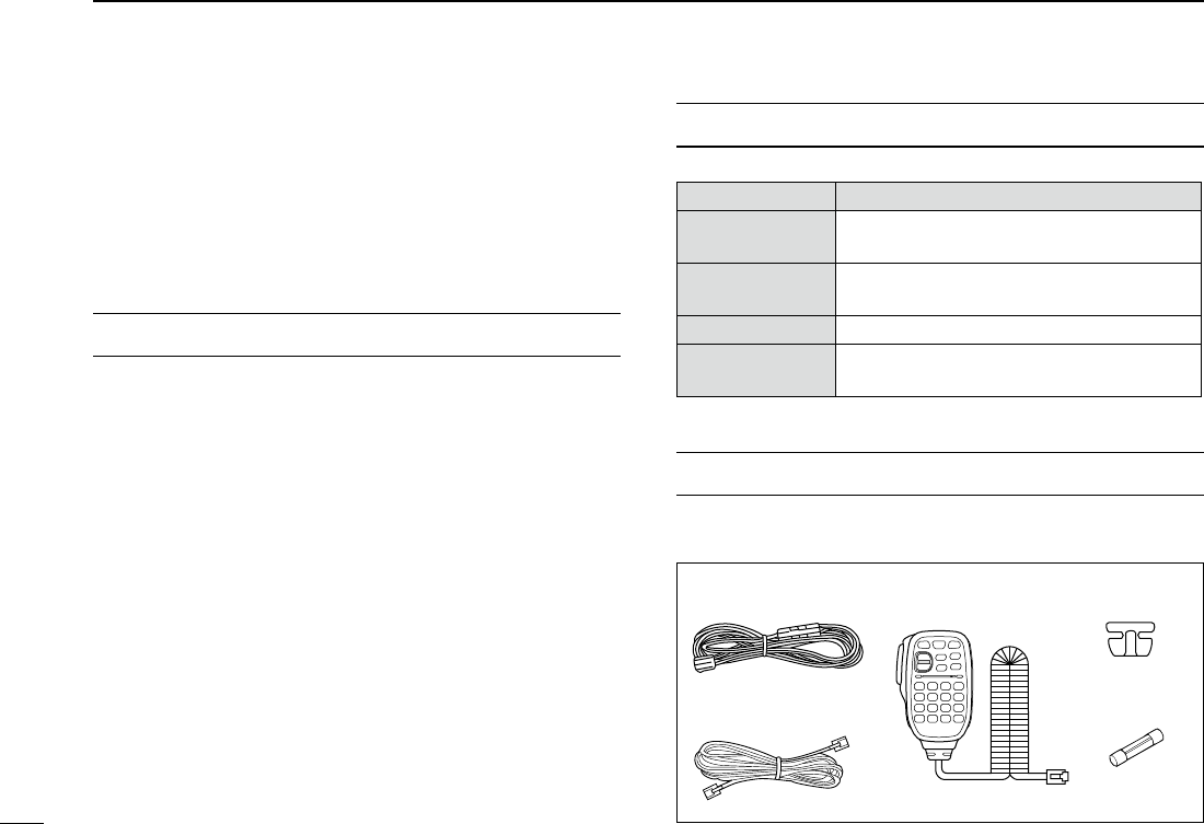
SUPPLIED ACCESSORIES
The following accessories are supplied with the transceiver.
DC power cable
(3 m: 9.8 ft)
Controller cable
(3.5 m:11.4 ft)
Microphone
(HM-207S)
Spare fuse
(FGB 15 A)
Microphone
hanger
EXPLICIT DEFINITIONS
WORD DEFINITION
RDANGER! Personal death, serious injury or an
explosion may occur.
RWARNING! Personal injury, re hazard or electric
shock may occur.
CAUTION Equipment damage may occur.
NOTE Recommended for optimum use. No risk
of personal injury, re or electric shock.
IMPORTANT
READ ALL INSTRUCTIONS carefully and completely
before using the transceiver.
SAVE THIS INSTRUCTION MANUAL— This instruction
manual contains basic operating instructions for the ID-
4100A/ID-4100E.
For Advanced features and instructions, see the Operating
Guide that is on the Icom website.

ID-4100A/ID-4100E BASIC MANUAL
New2001New2001
ii
ABOUT THE CONSTRUCTION OF THE MANUAL (As of April 2017)
You can see the following manuals to use and understand
this transceiver.
Basic manual (This manual)
Instructions for the basic operations, precautions,
installations, and connections.
D-STAR Guide (Comes with the transceiver)
Instructions for registering your call sign to a gateway
repeater or the basic operations of D-STAR.
About the DV Gateway function (PDF type)
Instructions for the system requirement or operations to use
the DV Gateway function.
Operating guide (PDF type)
Instructions for the advanced operations, as shown below.
• Memory operation
• Scan operation
• Priority watch operation
• D-STAR operation <Advanced>
• GPS operation
• Using a microSD card
• Voice memory operation
• Repeater and duplex operations
• Menu screen <Advanced>
• Other functions
• Options
• Bluetooth® operation
To read the guide or instructions, Adobe® Acrobat® Reader®
is required. If you have not installed it, please downloaded
the Adobe® Acrobat® Reader® from Adobe Systems
Incorporated’s website.

iii
New2001 New2001
ID-4100A/ID-4100E BASIC MANUAL
OPTIONS (As of April 2017)
Microphone/Speaker
HM-207S hand microphone (remote-control)
HM-209 noise canceling microphone
HM-232 hand microphone (simple)
OPC-440 mic extension cable: 5 m (16.4 ft)
OPC-647 mic extension cable: 2.5 m (8.2 ft)
SP-35 external speaker: 2 m (6.5 ft)
SP-35L external speaker: 6 m (19.6 ft)
SP-30 external speaker: 2.8 m (9.1 ft)
Software
CS-4100 cloning software
RS-MS1A Android™ application
RS-MS3W
terminal mode/access point mode software:
For Windows
RS-MS3A
terminal mode/access point mode application:
For Android™ devices
OPC-1529R data cable: RS-232C type
OPC-2350LU data cable: USB type
OPC0478UC cloning cable: USB type
Bluetooth
UT-137 Bluetooth® unit
VS-3 Bluetooth® headset
Others
MBA-8 controller bracket
MBF-1 mounting base
MBF-4 mobile bracket
OPC-345 dc power cable
OPC-589 mic adaptor cable
OPC-1156 controller extension cable: 3.5 m (11.4 ft)
Icom is not responsible for the destruction, damage to, or
performance of any Icom or non-Icom equipment, if the
malfunction is because of:
• Force majeure, including, but not limited to, res,
earthquakes, storms, oods, lightning, other natural
disasters, disturbances, riots, war, or radioactive
contamination.
• The use of Icom transceivers with any equipment that is
not manufactured or approved by Icom.

iv
New2001
ID-4100A/ID-4100E BASIC MANUAL
TABLE OF CONTENTS FOR YOUR PURPOSE

v
New2001 New2001
ID-4100A/ID-4100E BASIC MANUAL
RDANGER HIGH VOLTAGE! NEVER touch the antenna
connector during transmission. This may result in an
electrical shock or burn.
RDANGER! NEVER operate the transceiver near
unshielded electrical blasting caps or in an explosive
atmosphere.
RDANGER! NEVER place the transceiver where air bag
deployment may be obstructed during mobile operations.
RWARNING RF EXPOSURE! This transceiver emits
Radio Frequency (RF) energy. Extreme caution should be
observed when operating this transceiver. If you have any
questions regarding RF exposure and safety standards
please refer to the Federal Communications Commission
Ofce of Engineering and Technology’s report on Evaluating
Compliance with FCC Guidelines for Human Radio
Frequency Electromagnetic Fields (OET Bulletin 65).
RWARNING! NEVER operate the transceiver while driving
a vehicle. Safe driving requires your full attention—anything
less may result in an accident.
RWARNING! NEVER operate the transceiver with an
earphone or other audio accessories at high volume levels.
Continuous high volume operation may cause a ringing in
your ears. If you experience ringing, reduce the volume level
or discontinue use.
RWARNING! NEVER connect the transceiver to an AC
outlet. This may pose a re hazard or result in an electric
shock.
RWARNING! NEVER connect the transceiver to a power
source of more than 16 V DC such as a 24 V DC battery.
This could cause a re or damage the transceiver.
RWARNING! NEVER reverse the DC power cable polarity
when connecting to a power source. This could damage the
transceiver.
RWARNING! NEVER operate the transceiver during a
lightning storm. It may result in an electric shock, cause a
re or damage the transceiver. Always disconnect the power
souce and antenna before a storm.
RWARNING! NEVER cut the DC power cable between the
DC plug and fuse holder. If an incorrect connection is made
after cutting, the transceiver may be damaged.
RWARNING! NEVER let metal, wire or other objects touch
any internal part or connectors on the rear panel of the
transceiver. This may result in an electric shock or this could
cause a re or damage the transceiver.
RWARNING! NEVER operate or touch the transceiver
with wet hands. This may result in an electric shock or may
damage the transceiver.
PRECAUTIONS

vi
New2001
ID-4100A/ID-4100E BASIC MANUAL
PRECAUTIONS
RWARNING! NEVER operate the transceiver if it emits an
abnormal odor, sound or smoke. Immediately turn OFF the
transceiver power and remove the power cable. Contact
your Icom dealer or distributor for advice.
RWARNING! NEVER place the transceiver where normal
operation of the vehicle may be hindered or where it could
cause bodily injury.
CAUTION: DO NOT expose the transceiver to rain, snow or
any liquids.
CAUTION: DO NOT change the internal settings of the
transceiver. This may reduce transceiver performance and/
or damage the transceiver.
CAUTION: DO NOT use harsh solvents such as Benzine
or alcohol to clean the transceiver, as they will damage the
transceiver’s surfaces. If the transceiver becomes dusty or
dirty, wipe it clean with a soft, dry cloth.
CAUTION: DO NOT place or leave the transceiver in
areas with temperatures below –10°C (+14°F) or above
+60°C (+140°F). Be aware that temperatures on a vehicle’s
dashboard can exceed +80°C (+176°F) in direct sunlight,
resulting in permanent damage to the transceiver if left there
for long periods of time.
CAUTION: DO NOT start the vehicle engine when the
transceiver's power is ON. Ignition voltage spikes can
damage the transceiver.
CAUTION: DO NOT use non-Icom microphones. Other
manufacturer’s microphones have different pin assignments,
and may damage the transceiver.
DO NOT push the PTT when not actually desiring to
transmit.
DO NOT place the transceiver in excessively dusty
environments or in direct sunlight.
DO NOT place the transceiver against walls or putting
anything on top of the transceiver. This will obstruct heat
dissipation.
DO NOT place the transceiver in an insecure place to avoid
inadvertent use by unauthorized persons.
DO NOT place the transceiver where hot or cold air blows
directly onto it, during mobile operation.
DO NOT operate the transceiver without running the
vehicle’s engine, during mobile operation. When the
transceiver’s power is ON and your vehicle’s engine is OFF,
the vehicle’s battery will soon become exhausted.
NOTE: During maritime mobile operation, keep the
transceiver and microphone as far away as possible from
the magnetic navigation compass to prevent erroneous
indications.
BE CAREFUL! The rear panel will become hot when
continuously operating the transceiver for long periods of
time.

ID-4100A/ID-4100E BASIC MANUAL
vii
New2001 New2001
DÉFINITIONS EXPLICITES
MOT DÉFINITION
RDANGER! Risque d'accident mortel, de blessures
corporelles graves ou d'explosion.
RMISE EN
GARDE
Risque de blessures corporelles, d'incendie
ou de choc électrique.
ATTENTION Risque de dégât matériel.
REMARQUE
Inconvénient seulement, en cas de non-respect.
Absence de risque de blessures corporelles,
d'incendie ou de choc électrique.
MISE AU REBUT
Le pictogramme poubelle barrée sur notre produit,
notre documentation ou nos emballages vous
rappelle qu'au sein de l'Union européenne, tous les
produits électriques et électroniques, batteries et
accumulateurs (batteries rechargeables) doivent être
mise au rebut dans les centres de collecte indiqués à
la n de leur période de vie. Vous ne devez pas
mettre au rebut ces produits avec les déchets municipaux non triés.
Ils doivent être mis au rebut dans le respect de la réglementation en
vigueur dans votre secteur.
PRÉCAUTIONS
RDANGER HIGH VOLTAGE! NEVER touch the antenna
connector during transmission. This may result in an electrical
shock or burn.
RDANGER! NEVER operate the transceiver near unshielded
electrical blasting caps or in an explosive atmosphere.
RDANGER! NEVER place the transceiver where air bag
deployment may be obstructed during mobile operations.
RWARNING RF EXPOSURE! This transceiver emits Radio
Frequency (RF) energy. Extreme caution should be observed
when operating this transceiver. If you have any questions
regarding RF exposure and safety standards please refer to the
Federal Communications Commission Ofce of Engineering and
Technology’s report on Evaluating Compliance with FCC Guidelines
for Human Radio Frequency Electromagnetic Fields (OET Bulletin
65).
RWARNING! NEVER operate the transceiver while driving a
vehicle. Safe driving requires your full attention—anything less may
result in an accident.
RWARNING! NEVER operate the transceiver with an earphone
or other audio accessories at high volume levels. Continuous
high volume operation may cause a ringing in your ears. If you
experience ringing, reduce the volume level or discontinue use.
RWARNING! NEVER connect the transceiver to an AC outlet.
This may pose a re hazard or result in an electric shock.
RWARNING! NEVER connect the transceiver to a power source
of more than 16 V DC such as a 24 V DC battery. This could cause
a re or damage the transceiver.
RWARNING! NEVER reverse the DC power cable polarity when
connecting to a power source. This could damage the transceiver.

ID-4100A/ID-4100E BASIC MANUAL
New2001
viii
1
2
3
4
5
6
7
8
9
10
11
12
13
14
15
16
17
18
19
PRÉCAUTIONS
RWARNING! NEVER operate the transceiver during a lightning
storm. It may result in an electric shock, cause a re or damage the
transceiver. Always disconnect the power souce and antenna before
a storm.
RWARNING! NEVER cut the DC power cable between the DC
plug and fuse holder. If an incorrect connection is made after
cutting, the transceiver may be damaged.
RWARNING! NEVER let metal, wire or other objects touch any
internal part or connectors on the rear panel of the transceiver. This
may result in an electric shock or this could cause a re or damage
the transceiver.
RWARNING! NEVER operate or touch the transceiver with wet
hands. This may result in an electric shock or may damage the
transceiver.
RWARNING! NEVER operate the transceiver if it emits an
abnormal odor, sound or smoke. Immediately turn OFF the
transceiver power and remove the power cable. Contact your Icom
dealer or distributor for advice.
RWARNING! NEVER place the transceiver where normal
operation of the vehicle may be hindered or where it could cause
bodily injury.
CAUTION: DO NOT expose the transceiver to rain, snow or any
liquids.
CAUTION: DO NOT change the internal settings of the transceiver.
This may reduce transceiver performance and/or damage the
transceiver.
CAUTION: DO NOT use harsh solvents such as Benzine or alcohol
to clean the transceiver, as they will damage the transceiver’s
surfaces. If the transceiver becomes dusty or dirty, wipe it clean with
a soft, dry cloth.
CAUTION: DO NOT place or leave the transceiver in areas with
temperatures below –10°C (+14°F) or above +60°C (+140°F). Be
aware that temperatures on a vehicle’s dashboard can exceed
+80°C (+176°F) in direct sunlight, resulting in permanent damage to
the transceiver if left there for long periods of time.
CAUTION: DO NOT start the vehicle engine when the transceiver's
power is ON. Ignition voltage spikes can damage the transceiver.
CAUTION: DO NOT use non-Icom microphones. Other
manufacturer’s microphones have different pin assignments, and
may damage the transceiver.
DO NOT push the PTT when not actually desiring to transmit.
DO NOT place the transceiver in excessively dusty environments or
in direct sunlight.
DO NOT place the transceiver against walls or putting anything on
top of the transceiver. This will obstruct heat dissipation.
DO NOT place the transceiver in an insecure place to avoid
inadvertent use by unauthorized persons.
DO NOT place the transceiver where hot or cold air blows directly
onto it, during mobile operation.
DO NOT operate the transceiver without running the vehicle’s
engine, during mobile operation. When the transceiver’s power is
ON and your vehicle’s engine is OFF, the vehicle’s battery will soon
become exhausted.
NOTE: During maritime mobile operation, keep the transceiver and
microphone as far away as possible from the magnetic navigation
compass to prevent erroneous indications.
BE CAREFUL! The rear panel will become hot when continuously
operating the transceiver for long periods of time.

ix
New2001 New2001
ID-4100A/ID-4100E BASIC MANUAL
Icom n'est pas responsable de la destruction ou des dommages
sur l'émetteur-récepteur Icom, si le dysfonctionnement est causé
par :
• Force majeure, sans toutefois s'y limiter, les incendies,
tremblements de terre, tempêtes, inondations, la foudre, ou
autres catastrophes naturelles, perturbations, émeutes, guerre,
ou contamination radioactive.
• L'utilisation de l'émetteur-récepteur Icom avec tout équipement
non fabriqué ou approuvé par Icom.
PRÉCAUTIONS (Continued) INFORMATION FCC
• POUR LES RAYONNEMENTS NON INTENTIONNELS DE
CLASSE B:
Cet équipement a été testé et reconnu conforme aux limites xées
pour un appareil numérique de classe B, conformément au point 15
de la réglementation FCC. Ces limites ont été xées an d'assurer
une protection raisonnable contre les interférences nocives dans
une installation résidentielle.
Cet équipement génère, utilise et peut émettre un rayonnement
de fréquence radio. S'il n'a pas été installé conformément aux
instructions, il peut par ailleurs créer des interférences perturbant
les communications radio. Toutefois, il n'y a aucune garantie que les
interférences ne se produiront pas dans une installation particulière.
Si cet équipement crée des interférences perturbant la réception
de la radio ou de la télévision, comme cela peut être déterminé
en éteignant et en allumant l'équipement, l'utilisateur est invité à
essayer de corriger l'interférence en prenant une ou plusieurs des
mesures ci-après:
• Réorienter ou changer de place l'antenne de réception.
• Éloigner l'équipement et le récepteur.
• Connecter l'équipement sur une prise sur un autre circuit que celui
sur lequel le récepteur est connecté.
• Faire appel au revendeur ou à un technicien radio/TV
expérimenté.
MISE EN GARDE: Tout changement ou modication, non
expressément approuvé par Icom Inc., peut annuler l'autorisation
de l'utilisateur à utiliser cet appareil conformément à la
réglementation FCC.
x
New2001
ID-4100A/ID-4100E BASIC MANUAL
DWhen using the GPS receiver
• GPS signals cannot pass through metal objects. When
using the transceiver inside a vehicle, you may not receive
GPS signals. We recommend you use it near a window.
Please avoid the areas where:
1. The driver’s view will be blocked.
2. The air bags could deploy.
3. The unit becomes a driving obstacle.
• The Global Positioning System (GPS) is built and operated
by the U.S. Department of Defense. The Department is
responsible for accuracy and maintenance of the system.
Any changes by the Department may affect the accuracy
and function of the GPS system.
• When the GPS receiver is activated, please do not cover
the remote controller with anything that will block the
satellite signals.
• The GPS receiver may not work if used in the following
locations:
1. Tunnels or high-rise buildings
2. Underground parking lots
3. Under a bridge or viaduct
4. In remote forested areas
5. Under bad weather conditions (rainy or cloudy day)
IMPORTANT NOTES
DSpurious signals
Spurious signals may occur at some frequencies. These are
created in the internal circuit and does not indicate a transceiver
malfunction. You may avoid the spurious signals with the
Heterodyne function. (p. ??)
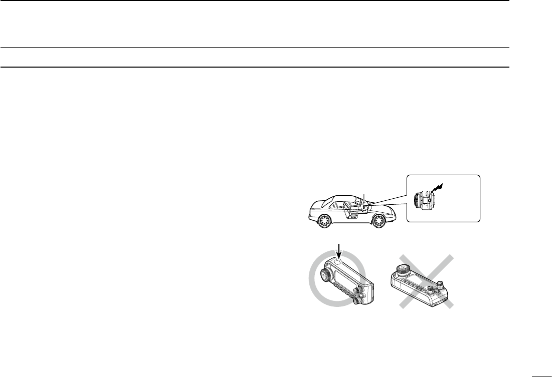
DAbout GPS antenna
This transceiver’s GPS antenna is located at the top back
of the controller. If the controller’s rear panel is covered with
any object that interrupts the GPS signals from the satellites,
the GPS receiver will not calculate its position. Therefore,
when you are using the GPS feature, be sure the controller
is positioned so the antenna has a clear view to receive
signals from the satellites.
GPS
antenna
Controller
GPS antenna

ID-4100A/ID-4100E BASIC MANUAL
xi
New2001 New2001
TABLE OF CONTENTS

ID-4100A/ID-4100E BASIC MANUAL
New2001
xii
TABLE OF CONTENTS (Continued)
Icom, Icom Inc. and Icom logo are registered trademarks of Icom Incorporated
(Japan) in Japan, the United States, the United Kingdom, Germany, France,
Spain, Russia, Australia, New Zealand, and/or other countries.
Adobe and Adobe Reader are either registered trademarks or trademarks of
Adobe Systems Incorporated, in the United States and/or other countries.
The Bluetooth word mark and logos are registered trademarks owned by the
Bluetooth SIG, Inc. and any use of such marks by Icom Inc. is under license.
Other trademarks and trade names are those of their respective owners.
Android and the Android logo are trademarks of Google, Inc.
IOS is a trademark or registered trademark of Cisco in the U.S. and other
countries and is used under license.
All other products or brands are registered trademarks or trademarks of their
respective holders.
New2001
1
New2001New2001
INSTALLATION AND CONNECTIONS
1
ID-4100A/ID-4100E BASIC MANUAL
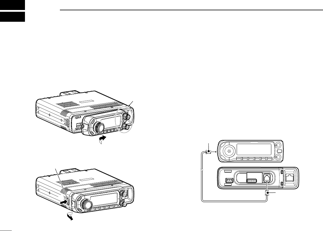
■Installing the controller
D When attaching to the main unit
Attaching:
Slide the controller in the direction of the arrow until the
controller is locked and makes a ‘click’ sound.
Detaching:
1. Push the release button on the main unit. (q)
2. Slide the controller to the left (w), then pull it out. (e)
D When connecting to the main unit
Connect the controller to the main unit with the supplied
control cable.
L The following longer cables are usable, depending on the
installation location.
• OPC-440 mic extension cable: 5 m (16.4 ft)
• OPC-647 mic extension cable: 2.5 m (8.2 ft)
• OPC-1156 controller extension cable: 3.5 m (11.4 ft)
• SP-35 external speaker: 2 m (6.5 ft)
• SP-35L external speaker: 6 m (19.6 ft)
• SP-30 external speaker: 2.8 m (9.1 ft)
Main unit
Controller
Place the unit’s
tabs into the
controller’s slots.
w
q
e
Release button
Main unit
Controller
Main unit
6-pin connector
6-pin connector
2
1
INSTALLATION AND CONNECTIONS
New2001
1
ID-4100A/ID-4100E BASIC MANUAL
New2001
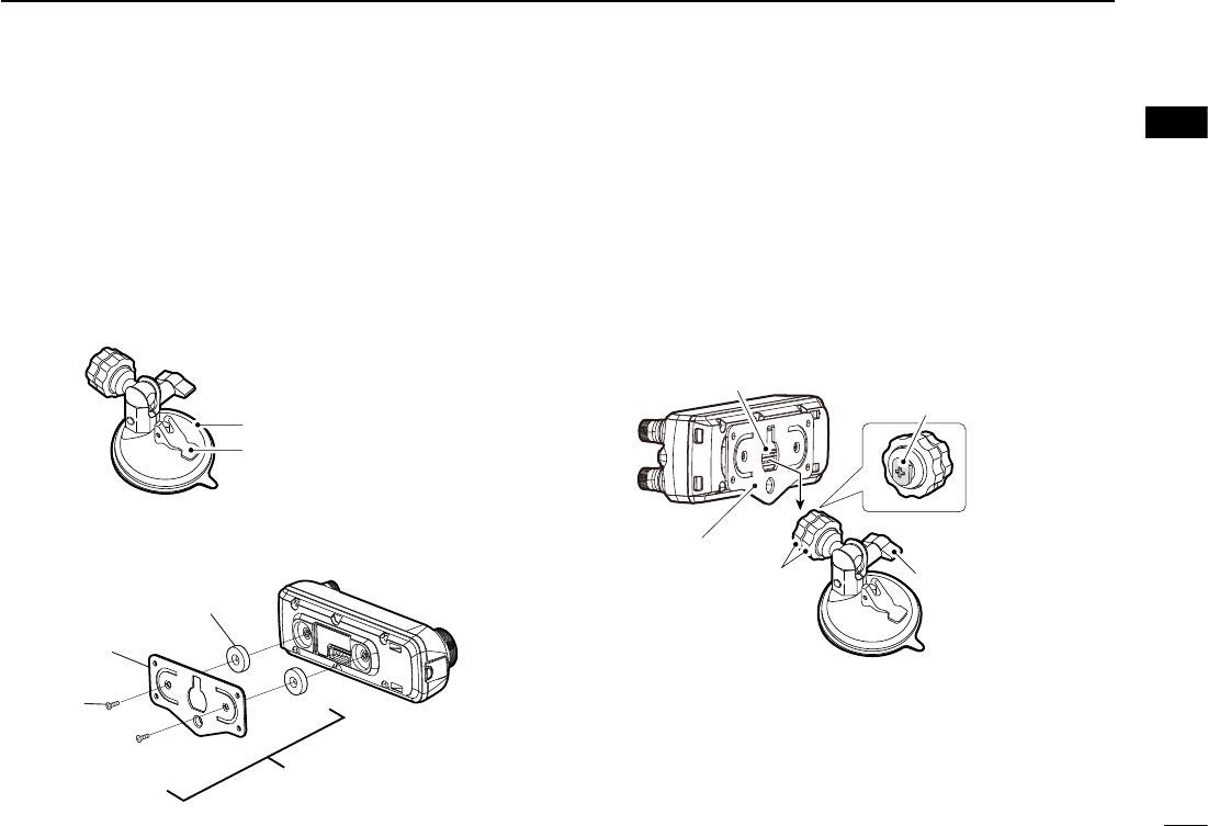
3. Slide the MBA-8’s guide down over the MBF-1’s locking
head, as shown below.
L Be sure the locking head ts into the slot at the top of the
guide.
4. Tighten the lock knob to securely attach the controller.
5. Adjust the viewing angle of the controller, then tighten
the adjustment knob.
Guide
MBA-8
Lock knob
Locking head
(MBF-1)
Adjustment knob
■Installing the controller
DWhen installing into your vehicle
You can install the controller on the dashboard or the
console of your vehicle with the optional MBA-8 controller
bracket and the MBF-1 mounting base. (p. ??)
1. Attach the MBF-1 to the dashboard or the console.
LSee the MBF-1 instruction manual for details.
Magnet
Controller
bracket
Screw
(M2.6×8)
MBA-8
Suction pad
Base lever
MBF-1
2. Attach the MBA-8 to the controller’s rear panel with the
two supplied screws, as shown below.
Controller
Controller
3
1INSTALLATION AND CONNECTIONS
New2001 New2001
ID-4100A/ID-4100E BASIC MANUAL
■Installing the controller (Continued)
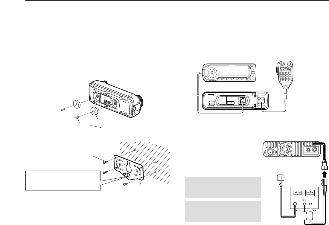
DAttaching to a at surface
You can install the controller on a at surface with the
optional MBA-8 controller bracket.
When attaching the MBA-8 to a wall, use self-tapping
screws* (3 mm, 0.12 in (d)).
Magnet
Screw Supplied with the MBA-8
1. Attach the magnets to the controller.
MBA-8
Self-tapping screw*
(3 mm, 0.12 in (d))
■ Connecting a microphone
Plug in the microphone into the microphone jack on the
main unit.
Controller
Main unit
Microphone
⊕
−
■ Connecting to a DC power
supply
Conrm that the transceiver is
OFF, then connect to a 13.8 V
DC power source with at least
15 A capacity.
RWARNING! NEVER
remove the fuse holders from
the DC power cable.
When you attach a screw to this
hole, use a self-tapping screw*
(4 mm, 0.2 in (d)).
Controller
2. Attach the MBA-8 to a wall.
DC power
supply 13.8 V
Red line: +
Black line: _
To an
AC
outlet
Fuses 15 A
CAUTION: DO NOT reverse
the polarity when connecting
the DC power cable.
* User supplied
3. Attach the controller to the MBA-8 that is attached to a
wall.
4
1
INSTALLATION AND CONNECTIONS
New2001
1
ID-4100A/ID-4100E BASIC MANUAL
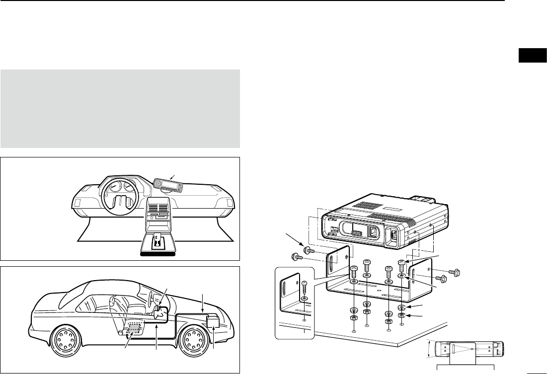
■Installing in a vehicle
CAUTION: DO NOT place the main unit or remote
controller where normal operation of the vehicle may be
hindered or where it could cause bodily injury.
CAUTION: DO NOT place the main unit or remote
controller where air bag deployment may be obstructed.
CAUTION: DO NOT place the transceiver or remote
controller where hot or cold air blows directly onto it.
Controller
Remote controller
installation
Controller DC power
cable
Battery
(12 V)
Controller
cable
Main unit
Main unit
installation
DUsing the mounting bracket
You can install the main unit on the dashboard or the
console of your vehicle with the optional MBF-4 mobile
bracket.
1. Drill 4 holes where the mounting bracket is to be
installed.
L Approximately 5.5 ~ 5.6 mm (0.21 ~ 0.22 inch)(d) when
using nuts, approximately 2 ~ 3 mm (0.08 ~ 0.12 inch)(d)
when using self-tapping screws.
2. Insert the supplied screws, nuts and washers through
the mounting bracket and tighten.
3. Adjust the angle to suit your needs.
Mounting
nut
Nut
Spring washer
When using self-
tapping screws
Flat washer
Screw
25º
5
1INSTALLATION AND CONNECTIONS
New2001 New2001
ID-4100A/ID-4100E BASIC MANUAL
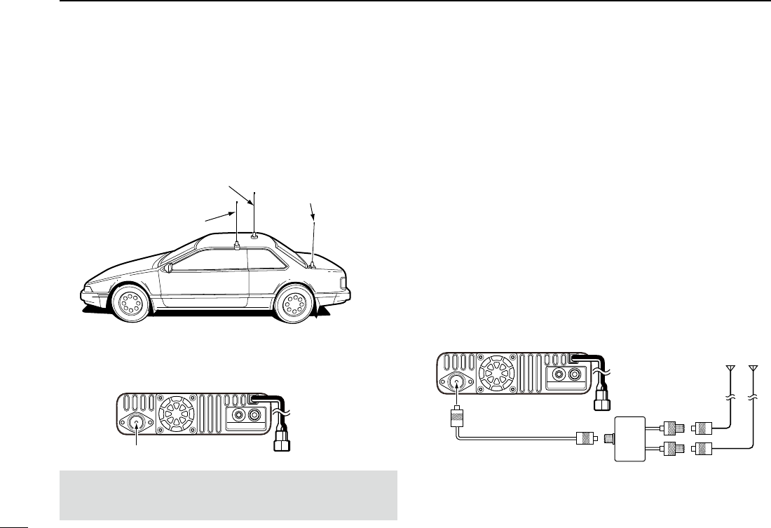
■Installing an antenna
To obtain maximum performance from the transceiver, select
a high-quality antenna and mount it in a good location.
Antenna location
NOTE:
• Make the coaxial cable as short as possible.
• Be sure to seal the antenna connection.
DAbout the antenna
For radio communications, the antenna is of critically
importance, along with output power and receiver sensitivity.
Select a well-matched 50 Ω antenna and coaxial cable
feedline. We recommend 1.5:1 or better Voltage Standing
Wave Ratio (VSWR) on your operating bands.
DAbout the internal duplexer
The transceiver has an internal duplexer, and you can easily
connect a dual band antenna.
If you connect separate the VHF and UHF antennas, use an
external duplexer.
When you connect VHF and UHF antennas separately:
Gutter-mount antenna
Roof-mount antenna
(Drill a hole or use a magnetic mount.)
Trunk-mount antenna
Connect the antenna to the antenna connector on the rear
panel of the main unit.
Antenna connector
To the
Antenna connector
Main unit
Main unit
6
1
INSTALLATION AND CONNECTIONS
New2001
1
ID-4100A/ID-4100E BASIC MANUAL
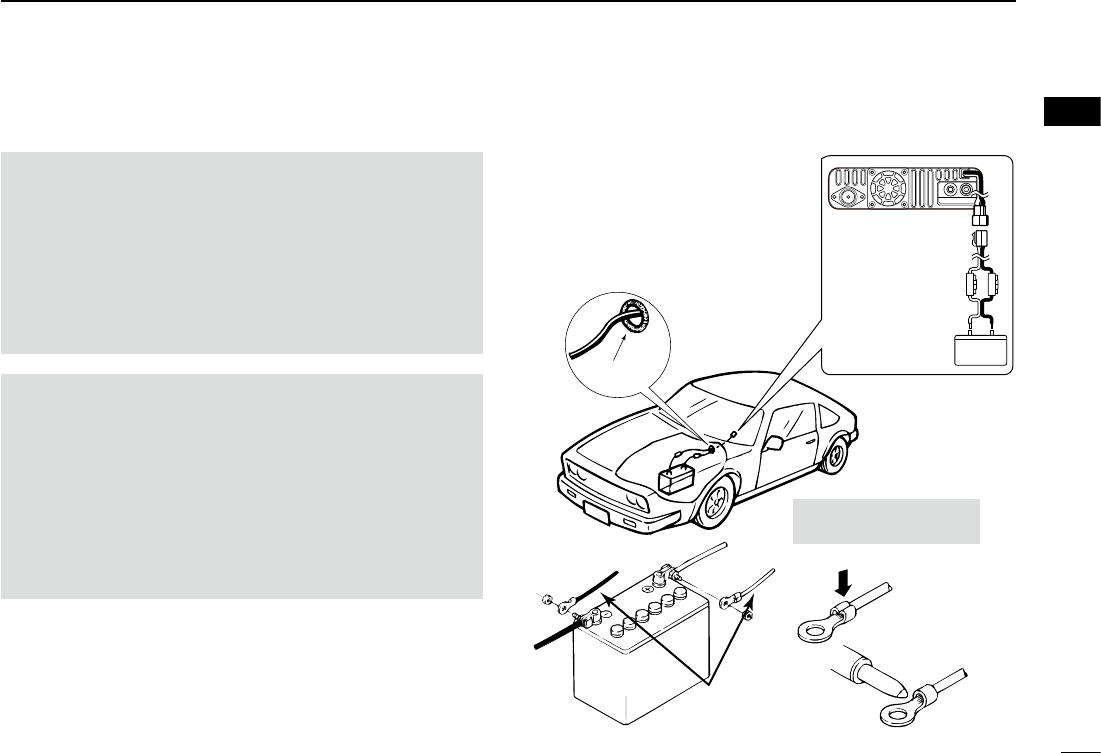
■Connecting to a battery
RWARNING!
• NEVER remove the fuses from the cable connecting the
transceiver to a power source, especially a car battery.
• NEVER connect the transceiver directly to a 24 V
battery. The transceiver may not receive well on some
frequencies when installed in a hybrid vehicle, or any
type of electric vehicle (fuel cell vehicle). This is because
vehicle’s electric components, such as the inverter
system, generate a lot of electrical noise.
CAUTION:
• DO NOT use a cigarette lighter socket as a power source
when operating in a vehicle. The plug may cause voltage
drops and ignition noise may be superimposed onto
transmit or receive audio.
• DO NOT pull or bend the DC power cable.
• DO NOT reverse the polarity when connecting the DC
power cable.
• Use a rubber grommet when passing the DC power cable
through a metal plate to prevent a short circuit.
Black Red
Crimp
Solder
Supplied
DC power cable
12 V
battery
NOTE: Use terminals for
the cable connections.
Grommet
CONNECTING TO A
VEHICLE BATTERY
_ Black + Red
Fuse holders
Battery
Red line: +
Black line: _
12 V
7
1INSTALLATION AND CONNECTIONS
New2001 New2001
ID-4100A/ID-4100E BASIC MANUAL
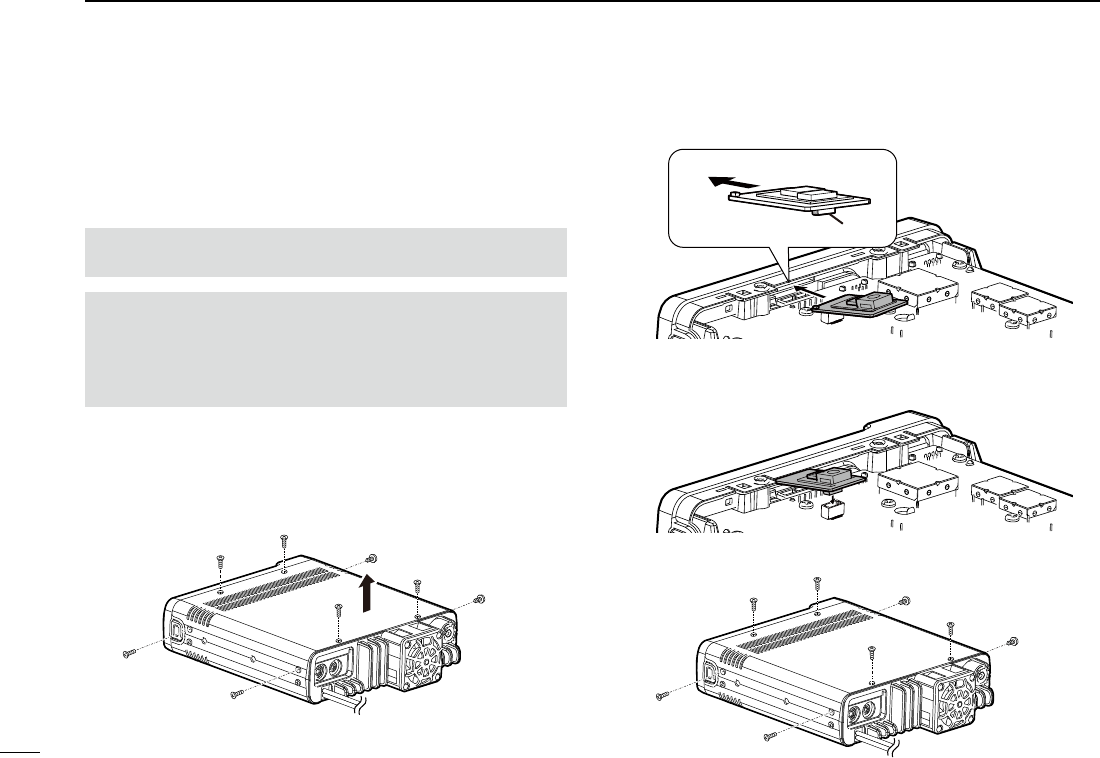
■Installing the UT-137
When you install the optional UT-137 Bluetooth® unit in
the transceiver, you can communicate with other Bluetooth
device.
1. Turn the transceiver upside-down.
2. Remove the three screws from the bottom of the
transceiver and the four screws from the sides, then lift
off the bottom cover.
WARNING! BE SURE TO disconnect the DC power cable
before starting the following procedures.
NOTE: Before touching the transceiver or UT-137, remove
static electricity from your body by touching a grounded
object such as a grounded piece of equipment. The static
electricity from your body may damage the transceiver or
the UT-137, or cause data lost.
3. Place one end the UT-137 under the edge of the front
panel, with the connector facing down.
4. Carefully, push the connector into the socket.
LEnsure the UT-137 is installed correctly.
5. Reattach the bottom cover and screws.
Bottom
cover
Front panel UT-137
Connector

8
1
INSTALLATION AND CONNECTIONS
New2001
1
ID-4100A/ID-4100E BASIC MANUAL
■Electromagnetic Interference
When you use a Bluetooth device, pay attention to the
following:
Bluetooth devices operate on the 2.4 GHz band.
The 2.4 GHz band is also used by other devices, such as
Wireless LAN products, microwave ovens, RFID systems,
amateur radio stations, and so on.
When using the Bluetooth device near such devices,
interference may occur, causing a decrease in
communication speed, and an unstable connection. In such
cases, use this device away from the other devices, or stop
using those devices.
New2001
1
New2001New2001
PANEL DESCRIPTION
2
ID-4100A/ID-4100E BASIC MANUALID-4100A/ID-4100E BASIC MANUAL
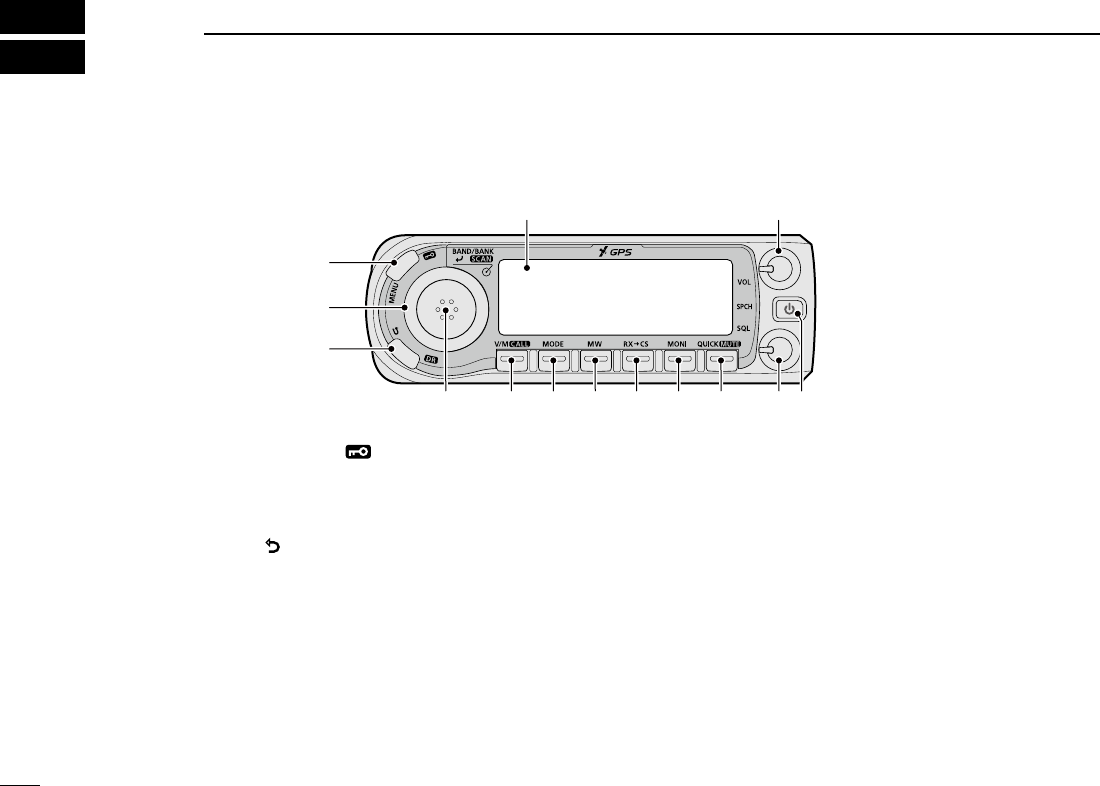
■Controller — Front panel
1MENU • LOCK KEY [MENU]( )
• Push to display the MENU screen.
• Hold down for 1 second to turn the Lock function ON or
OFF.
2CLEAR • DR KEY [](DR)
• Push to toggle between “TO” and “FROM” on the DR
screen.
• Push to go back a tree level of the MENU screen.
• Hold down for 1 second to display the DR screen.
3TUNING DIAL [DIAL]
• Selects an operating frequency.
• Selects an option of “TO” or “FROM” on the DR screen.
• Selects a Menu or Quick Menu item.
• Selects an option of the Menu or Quick Menu item.
• Selects a character in the Character Entry mode.
4BAND/BANK • ENTER • SCAN KEY
[BAND/BANK] [ï](SCAN)
• In the VFO mode, push to enter the Band Select mode.
• In the Memory mode, push to open the Bank Select
window.
• Push to set a Menu or Quick Menu item option.
• Hold down for 1 second to open the Scan Type Select
window.
• Hold down for 3 seconds to start the last selected scan.
5VFO/MEMORY • CALL KEY [V/M](CALL)
• Push to toggle between the VFO and Memory modes.
• In the Call channel mode, push to cancel the mode.
• Hold down for 1 second to enter the Call channel mode.
6MODE KEY [MODE]
Push to select an operating mode.
q
w
e
r t y u i o !0 !1 !2
!3
Display (p. ??)

2
2
PANEL DESCRIPTION
New2001
2
ID-4100A/ID-4100E BASIC MANUAL
New2001
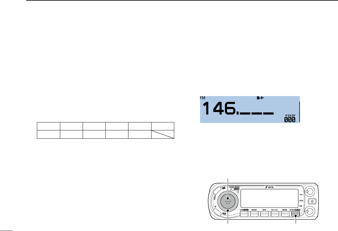
7MEMORY WRITE KEY [MW]
• Push to open the Memory Write window.
• Hold down for 1 second to save the operating data into
a blank channel.
• While the scan is paused, hold down for 1 second to set
the frequency as a skip channel.
8RX CALL SIGN CAPTURE KEY [RX→CS]
• Push to display the RX>CS screen.
• Hold down for 1 second to set the received station call
sign as the destination (UR) call sign.
9MONITOR KEY [MONI]
Push to turn the Monitor function ON or OFF.
QUICK MENU • MUTE KEY [QUICK] (MUTE)
• Push to open the Quick Menu window.
• Hold down for 1 second to turn the Mute function ON or
OFF.
SQUELCH CONTROL [SQL]
Adjusts the squelch level.
L Normally, set the squelch level to where noise and the
“BUSY” icon just disappear. (closed)
L The RF attenuator activates and increases the attenuation
when rotated clockwise at beyond the center position.
POWER • SPEECH KEY [ ](SPCH)
• Push to audibly announce the displayed frequency,
operating mode or call sign.
• Hold down for 1 second to turn the transceiver ON or
OFF.
MICROPHONE CONNECTOR (p. ??)
Connects the supplied or an optional microphone.
VOLUME CONTROL [VOL]
Adjusts the audio volume level.
3
2PANEL DESCRIPTION
New2001 New2001
ID-4100A/ID-4100E BASIC MANUAL
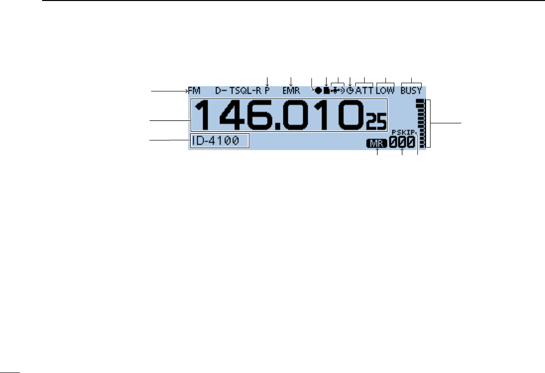
■Controller — Display
1MODE ICONS
Displays the selected operating mode.
2FREQUENCY READOUT
Displays the operating frequency.
3MEMORY NAME DISPLAY
4MEMORY MODE ICON
5MEMORY CHANNEL NUMBER
• Displays the selected Memory channel number, Memory
Bank, and so on.
• “WX” is displayed when the Weather channel mode is
ON. (Only the USA version transceiver)
6SKIP ICON
• SKIP: Displayed when Memory Skip is selected.
• PSKIP: Displayed when Program Skip is selected.
7S/RF METER
• Displays the relative signal strength of the receive
signal.
• Displays the output power level of the transmit signal.
8BUSY/MUTE ICONS
• BUSY: Displayed while a signal is being received or the
squelch is open.
Blinks while the monitor function is activated.
• MUTE: Displayed while the mute is activated.
• TX: Displayed while transmitting.
9POWER ICONS
Displays the output power level of the transmit signal in
three levels.
LWhen you select high power, the power icon disappears.
q
w
e
r t y
u
io!0!1!3!6!7 !2
!4

4
2
PANEL DESCRIPTION
New2001
2
ID-4100A/ID-4100E BASIC MANUAL
S-METER SQUELCH/ATTENUATOR ICONS
• S SQL: Displayed when the S-meter squelch is
activated.
• “ATT: Displayed when the Attenuator function is
activated.
AUTO POWER OFF ICON
Displayed when the Auto power OFF function is ON.
GPS ICON
• Displays the status of the GPS receiver.
• is displayed when you set the GPS alarm.
microSD CARD ICON
• Displayed when a microSD card is inserted.
• Blinks while accessing the microSD card.
RECORD ICON
• : Displayed while the transceiver is recording.
• : Displayed while the recording is paused.
Bluetooth ICON
Displayed when you make a Bluetooth connection
between your transceiver that has the optional UT-137
Bluetooth unit installed and a Bluetooth device.
EMR/BK/PACKET LOSS/AUTO REPLY ICONS
• EMR: Displayed when you select the Enhanced
Monitor Request (EMR) mode.
• BK: Displayed when you select the Break-in (BK)
mode.
• L: Displayed when packet loss has occurred.
• : Displayed when you select the Automatic Reply
function.
PRIORITY ICON
Displayed when Priority watch is turned ON.
TONE ICONS
Mode: FM/FM-N
• TONE: Enables the subaudible tone encoder.
• TSQLS: Enables the tone squelch with the Pocket
Beep function.
• TSQL: Enables the Tone Squelch function.
• DTCSS: Enables the DTCS squelch with the Pocket
Beep function.
• DTCS: Enables the DTCS Squelch function.
• TSQL-R: Enables the Reverse Tone Squelch
function.
• DTCS-R: Enables the Reverse DTCS Squelch
function.
• DTCS (“DTCS” blinks):
When you transmit, the selected DTCS
code is superimposed on your normal
signal.
When you receive, the function is OFF.
• T-DTCS (“T” blinks):
When you transmit, the selected subaudible
tone is superimposed on your normal
signal.
When you receive, the DTCS squelch
opens only for a signal that includes a
matching DTCS code and polarity. (Audio
is heard)
5
2PANEL DESCRIPTION
New2001 New2001
ID-4100A/ID-4100E BASIC MANUAL
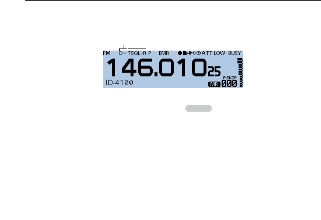
■Controller — Display (Continued)
!8 TONE ICONS (Continued)
• D-TSQL (“D” blinks):
When you transmit, the selected DTCS
code is superimposed on your normal
signal.
When you receive, the tone squelch opens
only for a signal that includes a matching
tone frequency. (Audio is heard)
• T-TSQL (“T” blinks):
When you transmit, the selected subaudible
tone is superimposed on your normal
signal.
When you receive, the tone squelch opens
only for a signal that includes a matching
tone frequency. (Audio is heard)
Mode: DV
• DSQLS: Enables the Digital Call Sign squelch
function with the Pocket Beep function.
• DSQL: Enables the Digital Call Sign squelch
function.
• CSQLS: Enables the Digital Code squelch function
with the Pocket Beep function.
• CSQL: Enables the Digital Code squelch function.
DUPLEX ICON
• “D–”: Displayed while the minus duplex operation.
• “D+”: Displayed while the plus duplex operation.
!8!9
6
2
PANEL DESCRIPTION
New2001
2
ID-4100A/ID-4100E BASIC MANUAL
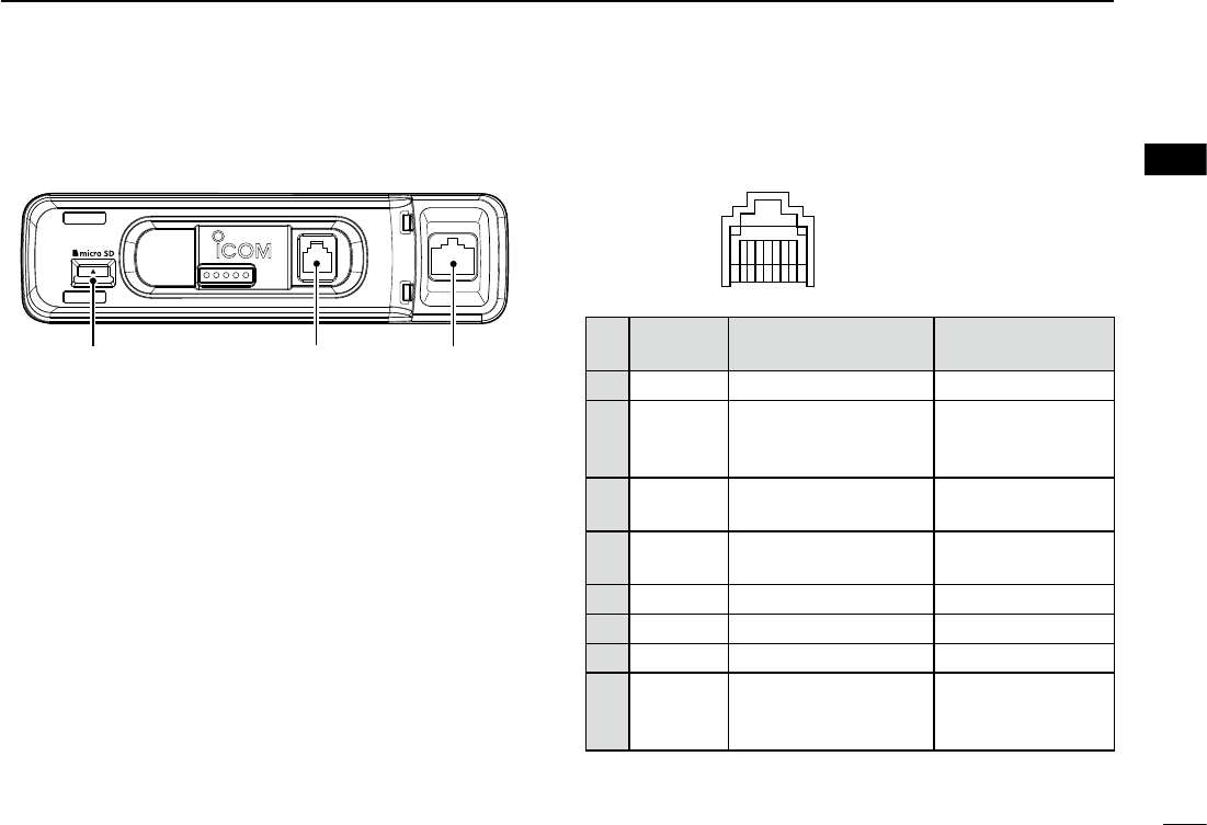
■Main unit — Front panel
1microSD CARD SLOT [micro SD]
Insert a microSD card (user supplied).
2CONTROLLER CONNECTOR
Connect to the controller using the supplied control cable.
3MICROPHONE CONNECTOR
Plug in the supplied or optional microphone.
DMicrophone connector information
12345678
Front panel view
PIN
No.
NAME DESCRIPTION SPECIFICATIONS
1 8 V +8 V DC output Maximum 10 mA
2MIC U/D Frequency Up/Down
UP: Ground
DN: Ground
through 470 ˘
3M8V SW Grounds when the
HM-207 is connected —
4 PTT PTT input Ground for
transmission
5MIC E Microphone ground —
6 MIC Microphone input —
7GND PTT ground —
8DATA IN
When the HM-207
is connected, inputs
HM-207 data
—
q w e
7
2PANEL DESCRIPTION
New2001 New2001
ID-4100A/ID-4100E BASIC MANUAL
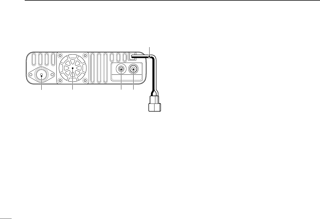
■Main unit — Rear panel
1ANTENNA CONNECTOR
Connect a 50 Ω impedance antenna with a PL-259
connector.
L The transceiver has a built-in duplexer, so you can use a 144
and 430 MHz dual-band antenna without needing an external
duplexer.
2COOLING FAN
The cooling fan for heat dissipation.
L You can select the Fan control option in the MENU screen,
and automatically start to rotate when you begin transmitting,
or continuously rotate from power ON.
3DATA JACK [DATA]
Connect a PC through the optional data communication
cable, for cloning or data communication in the DV mode.
4EXTERNAL SPEAKER JACK
Connect to an 8 Ω external speaker.
5DC POWER SOCKET [DC 13.8V]
Connect a 13.8 V DC power source through the supplied
DC power cable.
q w e r
t
8
2
PANEL DESCRIPTION
New2001
2
ID-4100A/ID-4100E BASIC MANUAL
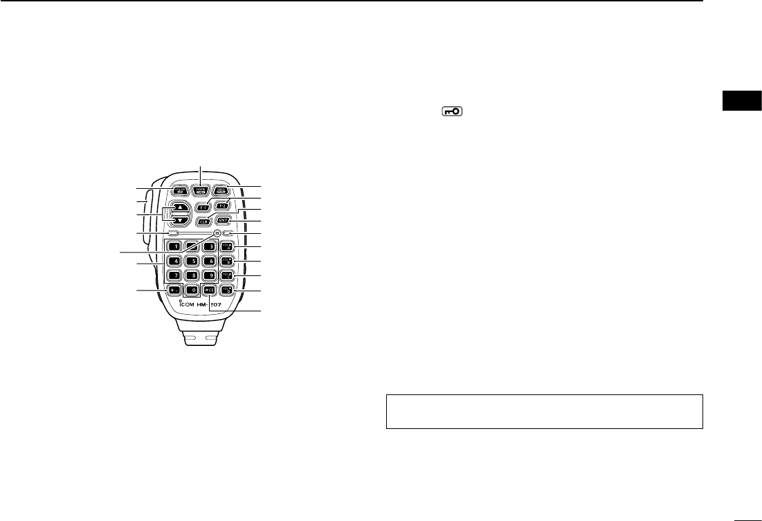
■Microphone (HM-207S)
With the HM-207S, you can input numbers for frequency or
Memory channel setting, and easily adjust the audio volume
or squelch level.
q
w
e
!0
t
y
i
u
o
r
!7
Mic element
!6
!1
!2
!3
!4
!5
1LED 1
Lights red while holding down [PTT].
2[∫]/[√] (UP/DOWN) KEYS
• Push to change the operating frequency or Memory
channel.
• Hold down to continuously change the frequency or
Memory channel.
3[PTT] SWITCH
Hold down to transmit, release to receive.
4[VFO/MR• ] KEY
• Push to toggle between the VFO and Memory modes.
• Hold down for 1 second to turn the Lock function ON or
OFF.
5[HOME/CALL] KEY
• Push to select the Home channel.
• Hold down for 1 second to enter or cancel the Call
channel mode.
6[BAND] KEY
Push to select the operating bands.
7[F-1] KEY
Push to activate the preset function of the [F-1] key.
(Default: During RX/Standby: [MODE]
During TX: [T-CALL])
[F-2] KEY
Push to activate the preset function of the [F-2] key.
(Default: During RX/Standby: [Monitor]
During TX: [---])
TIP: You can assign a desired function in the MENU
screen.
9
2PANEL DESCRIPTION
New2001 New2001
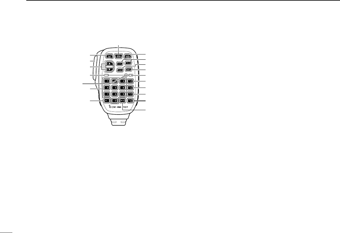
ID-4100A/ID-4100E BASIC MANUAL
[VOL√/B] KEY
• Push to decrease the audio output level.
• In the DTMF Code Entry mode, push to input ‘B.’
[SQL∫/C] KEY
• Push to increase the squelch level.
• In the DTMF Code Entry mode, push to input ‘C.’
[SQL√/D] KEY
• Push to decrease the squelch level.
• In the DTMF Code Entry mode, push to input ‘D.’
[#/CE] KEY
• In the Frequency Entry mode, push to delete a number.
• In the DTMF Code Entry mode, push to input ‘#.’
[M/.] KEY
• In the Frequency Entry mode, push to input a ‘.’
(decimal point).
• In the DTMF Code Entry mode, push to input ‘M.’
[0] to [9] KEYS
In the Frequency or DTMF Code Entry mode, push to
input ‘0’ through ‘9.’
q
w
e
!0
t
y
i
u
o
r
!7
Mic element
!6
!1
!2
!3
!4
!5
■Microphone (HM-207) (Continued)
8[CLR] KEY
Push to cancel the MENU screen or Quick Menu window,
then return to the standby screen.
9[ENT] KEY
• In the VFO mode, push to enter the Frequency Entry
mode.
• In the Memory mode, push to enter the Memory
Channel Number Entry mode.
• After entering the number, push to set.
LED 2
Lights green when transceiver’s power is ON.
[VOL∫/A] KEY
• Push to increase the audio output level.
• In the DTMF Code Entry mode, push to input ‘A.’

10
2
PANEL DESCRIPTION
New2001
2
ID-4100A/ID-4100E BASIC MANUAL
DSetting frequency and Memory channel
Example of frequency setting:
zFirst, push [VFO/MR] to select the VFO mode.
To enter the frequency 435.680 MHz:
zPush [4], [3], [5], [6], [8], [0], then [ENT].
To change 435.680 MHz to 435.540 MHz:
zPush [•], [5], [4], [0], then [ENT].
To enter the 433.000 MHz frequency:
zPush [4], [3], [3], then [ENT].
Example of Memory channel setting:
zFirst, push [VFO/MR] to select the Memory mode.
To select the Memory channel ‘5’:
zPush [5] then [ENT].
New2001
1
New2001New2001
BASIC OPERATION
3
ID-4100A/ID-4100E BASIC MANUALID-4100A/ID-4100E BASIC MANUAL
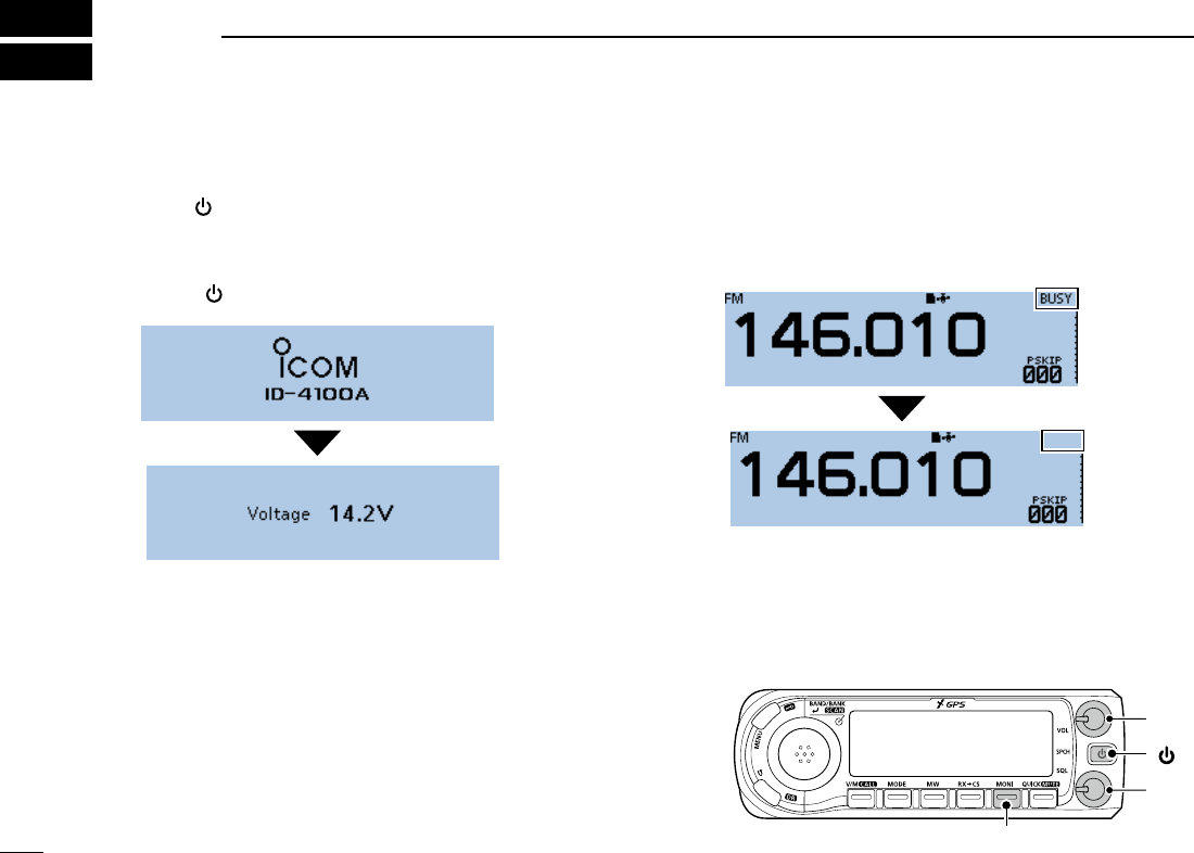
■Turning ON the power
Hold down [ ] for 1 second to turn ON the power.
• A beep sounds.
• After the opening message and power source voltage are
displayed, the operating frequency or repeater name is displayed.
LHold down [ ] for 1 second again to turn OFF the power.
■ Setting audio volume and
squelch level
1. Rotate [VOL] to adjust the audio level.
2. Rotate [SQL] until the noise and “BUSY” just disappear.
■Monitor function
The Monitor function is used to listen to weak signals
without disturbing the squelch setting.
Push [MONI] to open or close the squelch.
• “BUSY” blinks and audio is heard when the squelch is open.
• Rotating [SQL] clockwise makes the squelch tight. Tight
squelch is for strong signals.
• When rotating [SQL] clockwise beyond the center position,
[SQL] can be used as ‘S-meter Squelch’ or ‘Attenuator.’
Select the [SQL] option in the MENU screen. (p. ??)
(MENU > Function > Squelch/ATT Select)
[VOL]
[SQL]
[ ]
[MONI]
2
3
BASIC OPERATION
New2001
3
ID-4100A/ID-4100E BASIC MANUAL
New2001
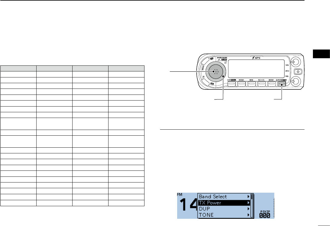
■Quick Menu window
In the Quick Menu window, the selectable items differ,
depending on the operating mode or function. The items
listed below are examples.
DQuick Menu window operation
[DIAL]
Selects an item
or option.
[QUICK]
Toggles between Quick
Menu window and the
standby screen.
[ï]
• Sets an option.
• Goes to a next
tree level.
Simplied description—‘Select’ operation
In this manual, user‘s ‘Select’ operation is simplied.
Simplied description:
1. Push [QUICK].
2. Select “TX Power,” then push [ï].
Operation:
1. Push [QUICK] to open the Quick Menu window.
2. Rotate [DIAL] to select “TX Power,” then push [ï].
VFO mode Memory mode Call CH mode DR function
Band Select Bank Select TX Power Group Select
TX Power TX Power DUP Repeater Detail
DUP DUP TONE TX Power
TONE TONE TS DTMF TX
MHz TS DTMF TX Voice TX
TS SKIP Voice TX RX History
DTMF TX DTMF TX
GPS Information GPS Information
Voice TX Voice TX GPS Position GPS Position
GPS Information GPS Information
Weather
Information*1
Weather
Information*1
GPS Position GPS Position
Temporary Skip*2Temporary Skip*2
Weather
Information*1
Weather
Information*1PRIO Watch PRIO Watch
Temporary Skip*2Temporary Skip*2
Weather CH
*3
Weather CH
*3
PRIO Watch PRIO Watch Weather Alert
*3
Weather Alert
*3
Weather CH
*3
Weather CH
*3
Display Type Home CH Set
Weather Alert
*3
Weather Alert
*3
Clock DSQL
Home CH Set Home CH Set Voltage SKIP
Clock Display Type Band Scope Clock
Voltage Clock <<REC Start>> Voltage
Band Scope Voltage <<REC Start>>
<<REC Start>> Band Scope
<<REC Start>>
*1 Displayed when the D-PRS TX format is set to “Weather.”
*2 Displayed while scanning.
*3 Displayed in only the USA version transceivers
3
3BASIC OPERATION
New2001 New2001
ID-4100A/ID-4100E BASIC MANUAL
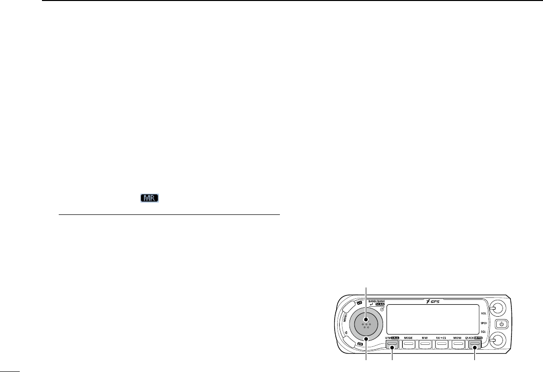
■Selecting the Mode
DVFO mode
You use the VFO mode to set the operating frequency.
DMemory mode
You use the Memory mode to operate on Memory channels.
DCall channel mode
You use the Call channel mode to operate on the Call
channels.
1. Push [V/M] several times until you enter the VFO or
Memory mode.
• In the Memory mode, and the selected Memory channel
number are displayed.
InformationL
• Pushing [V/M] toggles between the VFO and Memory modes.
• To enter the Call channel mode, hold down [V/M](CALL) for 1
second.
• In the Call channel mode, “144 C0,” “144 C1,” “430 C0,” or
“433 C1” is displayed.
• In the Call channel mode, push [V/M](CALL) to cancel the
mode.
2. Rotate [DIAL] to select an operating frequency or a
channel.
D Weather channel mode
(Selectable in only the USA version transceivers)
You can use the Weather channel mode to hear weather
broadcasts from the NOAA (National Oceanographic and
Atmospheric Administration) broadcasts.
1. Push [QUICK].
2. Rotate [DIAL] to select “WX CH,” then push [ï].
• The selected weather channel number (“WX-01” to “WX-10”)
is displayed.
L To cancel the mode, select “WX CH OFF” in the Quick Menu
window.
[QUICK][V/M](CALL)[DIAL]
[ï]
4
3
BASIC OPERATION
New2001
3
ID-4100A/ID-4100E BASIC MANUAL
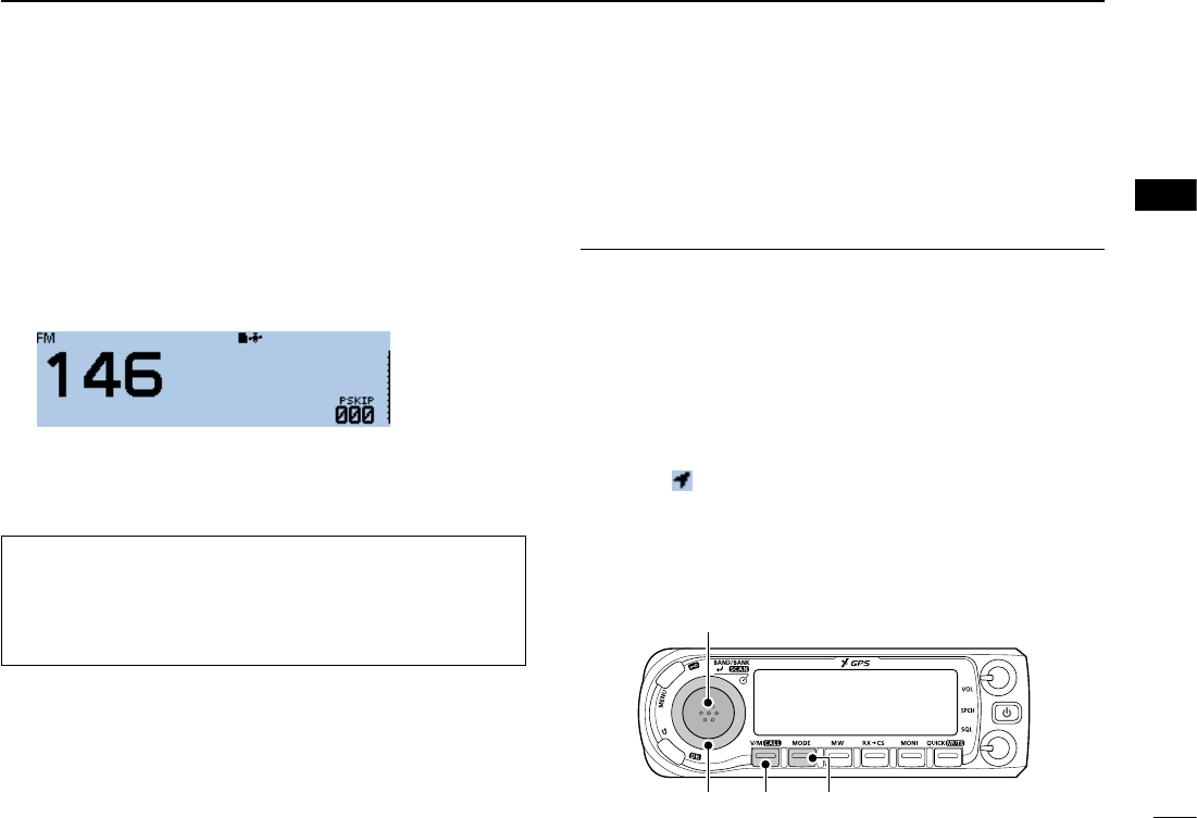
■Selecting the operating band
The transceiver can receive on the AIR, 144 MHz, 230 MHz,
300 MHz, and 430 MHz bands.
You can transmit on only the amateur band frequencies.
1. Push [V/M] several times until you enter the VFO mode.
2. Push [BAND].
• Enters the Band Select mode.
3. Rotate [DIAL] to select an operating band.
4. Push [ï].
• Sets the band, then returns to the standby screen.
■Selecting the operating mode
The transceiver has a total of 5 operating modes, AM, AM-N,
FM, FM-N, and DV. (Default: FM)
By pushing [MODE], you can select an operating mode.
InformationL
• You can select the AM mode for only the AIR, 230 MHz,
and 300 MHz bands.
• You can select the AM-N mode for only the AIR band.
• You can select the FM, FM-N, or DV modes for only the
144 MHz, 230 MHz, 300 MHz, and 430 MHz bands.
• While in the FM-N mode, the TX modulation is
automatically set to narrow (approximately ±2.5 kHz)
• When you set the “GPS TX Mode” item to “D-PRS” or
“NMEA,” is displayed besides the mode icon. (See the
Operating Guide on the Icom website for details.)
TIP: You can select the operating band in the Quick Menu
window.
1. Push [QUICK].
2. Rotate [DIAL] to select “Band Select,” then push [ï].
3. Select an operating band, then push [ï].
[MODE][V/M][DIAL]
[BAND]/[ï]
5
3BASIC OPERATION
New2001 New2001
ID-4100A/ID-4100E BASIC MANUAL
■Setting a frequency
DSelecting a tuning step
If you select the operating frequency by rotating [DIAL]
in the VFO mode, the frequency changes in the selected
tuning step.
L The VFO mode scan and the Band Scope function also
use this step to search for a signal.
1. Push [QUICK].
2. Rotate [DIAL] to select “TS,” then push [ï].
3. Select a tuning step, then push [ï].
Options (kHz):
5.0 6.25 8.33* 10.0 12.5 15
20 25 30 50 Auto*
*Selectable only in the AIR band mode.
• Sets the tuning step, then returns to the standby screen.
L You can set the tuning step for both the VFO and Memory
mode.
LYou can set the tuning step for each band.
DSelecting the 1 MHz tuning
You can change the operating frequency in ‘MHz’ steps for
quick tuning.
1. Push [QUICK].
2. Rotate [DIAL] to select “MHz,” then push [ï].
• Enters the 1 MHz Tuning Select mode.
3. Rotate [DIAL].
• The frequency changes in 1 MHz steps.
4. Push [ï].
• Sets the frequency, then returns to the standby screen.
[QUICK][DIAL]
[ï]
6
3
BASIC OPERATION
New2001
3
ID-4100A/ID-4100E BASIC MANUAL
■Lock function
You can use the Lock function to prevent accidental
frequency changes and unnecessary function access.
Hold down [ ] for 1 second to turn the Lock function ON or
OFF.
• “LOCk ON” or “LOCk OFF” is briey displayed when the Lock
function is turned ON or OFF.
L When the Lock function is ON and you operate the transceiver,
“LOCK” is displayed.
L You can still use [ ], [PTT], [SQL], [VOL] and [MONI], even if the
Lock function is ON.
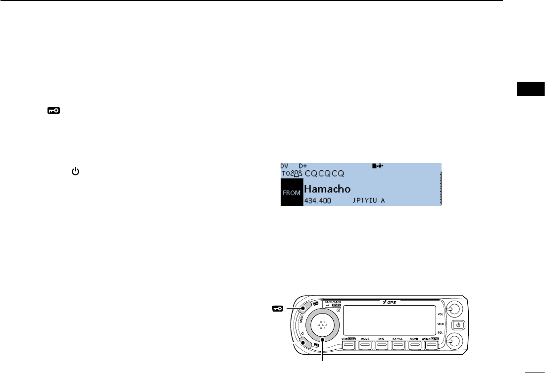
■ DR function
The DR (D-STAR Repeater) function is for D-STAR repeater
operation. This function enables you to easily select the
preset repeaters and UR call signs by rotating [DIAL].
See the D-STAR guide comes with transceiver for details.
1. Hold down [DR] for 1 second.
• Displays the DR screen.
2. Push [DR] several times until you select “FROM.”
3. Rotate [DIAL] to select an access repeater.
4. Push [DR].
• Cancels the DR screen.
[DR]
[ ]
[DIAL]
7
3BASIC OPERATION
New2001 New2001
ID-4100A/ID-4100E BASIC MANUAL
■Home Channel function
You can set the often-used frequency, Memory channel, or
repeater as the Home channel in each mode (VFO/Memory/
DR). The Home channels are selectable by pushing [HOME]
on the microphone in each mode.
L To select the Home channel by pushing [HOME], the
Home CH key function must be assigned into an [F-1] or
[F-2] key. See the Operating Guide on the Icom website
for details.
DSetting a Home channel
1. Select the VFO or Memory mode, or the DR screen to
set a Home channel. (pp. ??, ??)
2. Select a frequency, Memory channel, or an access
repeater to be set as a Home channel. (pp. ??, ??)
3. Push [QUICK].
4. Rotate [DIAL] to select “Home CH Set,” then push [ï].
5. Select “Set Frequency” (VFO mode), “Set Channel”
(Memory mode), or “Set Repeater” (DR screen), then
push [ï].
• Sets a Home channel, then returns to the standby screen.
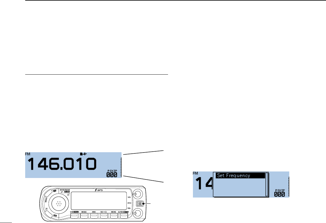
■Speech function
The Speech function audibly announces information
after pushing [SPCH]. Also, you can set various Speech
functions, such as the DIAL Speech function or Mode
Speech function on the MENU screen. (p. ??)
InformationL
• In the VFO, Memory, or Call channel mode, the Speech
function announces the displayed frequency and operating
mode.
• On the DR screen, the Speech function announces the
displayed call sign.
• When you push [SPCH] while recording the received audio
in the DV mode, the received audio will be muted, and no
audio is recorded onto the SD card. In modes other than
the DV mode, the received audio will be recorded.
One, four, six, point,
zero, one,
megahertz, FM.
[SPCH]
8
3
BASIC OPERATION
New2001
3
ID-4100A/ID-4100E BASIC MANUAL
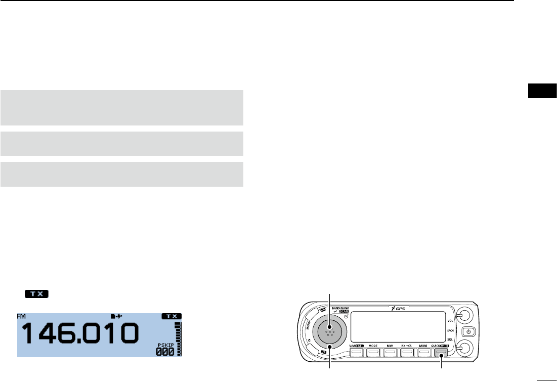
■Transmitting
DTransmitting on an Amateur band
Before transmitting, monitor the operating frequency
to make sure transmitting won’t cause interference to
other stations on the same frequency.
CAUTION: DO NOT transmit without an antenna. This
may damage the transceiver.
NOTE: You can transmit on only the amateur band
frequencies.
1. Set the operating frequency. (p. ??)
2. Push [QUICK].
3. Rotate [DIAL] to select “TX Power,” then push [ï].
• Opens the TX Power Select window.
4. Select the transmit output power level, then push [ï].
LSelect a level to suit your operating requirements.
LWhen you select high power, the power icon disappears.
5. Hold down [PTT] to transmit, and speak at your normal
voice level.
• is displayed while transmitting.
• The S/RF meter displays the output power level.
6. Release [PTT] to receive. [QUICK][DIAL]
[ï]

New2001
1
New2001New2001
MENU SCREEN
4
ID-4100A/ID-4100E BASIC MANUALID-4100A/ID-4100E BASIC MANUAL
■MENU screen description
The MENU screen is displayed after pushing [MENU].
You can use the MENU screen to set infrequently changed
values or function settings.
See the following pages for details of each set screen.
TIP: The MENU screen is constructed in a tree structure.
You may go to the next tree level, or go back a level,
depending on the selected item.
DUP/TONE... p. ??
Manage Memory p. ??
Scan p. ??
Voice Memo p. ??
Voice TX p. ??
GPS p. ??
Call Sign p. ??
RX History p. ??
DV Memory p. ??
My Station p. ??
DV Set p. ??
SPEECH p. ??
DTMF/T-CALL p. ??
QSO/RX Log p. ??
Function p. ??
Display p. ??
Sounds p. ??
Time Set p. ??
DV Gateway p. ??
SD Card p. ??
Bluetooth Set p. ??
Others p. ??
■Selecting a MENU item
DMENU screen operation
[MENU]
Switches between the MENU
screen and the standby screen.
[DIAL]
Selects an
item or option.
[QUICK]
Returns to the
default setting.
[]
Goes back the
tree level.
[ï]
• Sets an option.
• Goes to the
next tree level.
Simplied description—‘Select’ operation
In this manual, user‘s ‘Select’ operation is simplied as
shown below.
Simplied description:
Select “30min.”
Operation:
Rotate [DIAL] to select “30min.”

2
4
MENU SCREEN
New2001
4
ID-4100A/ID-4100E BASIC MANUAL
New2001
TIP: To return to the default setting:
1. Push [QUICK] in step 4.
2. Select “Default,” then push [ï].
DSelecting a Menu item
Example: Set the “Auto Power OFF” item to “30 min.”
Time Set > Auto Power OFF
1. Push [MENU].
2. Rotate [DIAL] to select “Time Set,” then push [ï].
3. Select “Auto Power OFF,” then push [ï].
4. Select “30min,” then push [ï].
• Sets the option, then goes back a tree level.
(TIME SET screen is displayed.)
5. Push [MENU].
• Returns to the standby screen.
■Menu items and their details
This topic describes the Menu items and their details.
DUP/TONE...
Settings to access repeaters.
Offset Freq
Sets the frequency offset for duplex (repeater) operation.
Repeater Tone
Selects a tone frequency used to access the repeaters.
TSQL Freq
Selects a tone frequency for the Tone Squelch or the Pocket Beep
function.
Tone Burst
Turns the Tone Burst function ON or OFF.
This function is used to suppress the squelch tail noise of FM
mode on the RX side, if you transmit a signal which superimposes
the CTCSS tone or subaudible tone.
DTCS Code
Selects a DTCS (both encoder/decoder) code for DTCS Squelch
or the Pocket Beep function.
DTCS Polarity
Selects the DTCS polarity for the DTCS Squelch or the Pocket
Beep function.
Digital Code
Selects a digital code for the Digital Code Squelch function.

3
4MENU SCREEN
New2001 New2001
ID-4100A/ID-4100E BASIC MANUAL
■Menu items and their details (Continued)
Manage Memory
Displays your Memory or Call channel data.
Memory CH
Displays the Memory channels.
Call CH
Displays the Call channels.
Scan
Set scan options.
Pause Timer
Selects the Scan Pause time. When receiving signals, the scan
pauses according to the this set period of time.
Resume Timer
Selects the Scan Resume time from a pause after the received
signal disappears.
Temporary Skip Timer
Selects the Temporary Skip time. When the time is set, specied
frequencies are skipped for this set period of time during a scan.
Program Skip
Turns the Program Skip Scan function ON or OFF for a VFO
mode scan.
Bank Link
Selects banks to be scanned during a Bank Link scan.
Program Scan Edge
Sets the frequency ranges for a Program scan.
Program Link
Sets the Link function for the Program Scan Edge channels. See
the Operating Guide on the Icom website for details.
Voice Memo
Set the TX/RX voice recording options.
QSO Recorder
Set QSO recorder options.
<<REC Start>>*
Starts recording the received signal audio.
Play Files*
Plays the recorded audio.
Recorder Set
REC Mode
Selects whether or not to record the TX audio.
RX REC Condition
Selects whether or not the squelch status affects the RX voice
audio recording.
File Split
Selects whether or not to automatically create a new le if
transmission and reception, or squelch status (open and close)
is changed.
PTT Auto REC
Turns the PTT Automatic Recording function ON or OFF.
Player Set
Skip Time
Sets the Skip time to rewind or forward the recorded audio
when you push the fast-rewind or fast-forward key during
playback.
DV Auto Reply*
Records a voice audio to use for the Auto Reply function in the DV
mode.
*A microSD card is required.

4
4
MENU SCREEN
New2001
4
ID-4100A/ID-4100E BASIC MANUAL
Voice TX
Set microphone voice recording options.
Record*
Starts recording the microphone audio.
TX Set
Repeat Time
Sets the repeat interval. The transceiver repeatedly transmits the
recorded voice audio at this interval.
TX Monitor
The TX Monitor function outputs the TX voice audio from the
speaker during voice transmission.
<<TX>>*
The transceiver transmits the recorded voice audio.
GPS
Set GPS options.
GPS Set
GPS Select
Selects either the internal or an external GPS receiver that the
transceiver receives its position data from.
Manual Position
Manually enter your current position.
GPS Out (To DATA jack)
Turns the output of GPS information from the internal GPS
receiver to the [DATA] jack ON or OFF.
GPS TX Mode
Set the GPS TX mode.
OFF
Turns OFF the GPS TX function.
D-PRS (DV-A) (GPS > GPS TX Mode)
Set D-PRS options.
Unproto Address
Enters an unproto address, or keeps the default.
TX Format
Position
Symbol
Selects a desired D-PRS Symbol to transmit.
SSID
Selects the APRS® call sign SSID.
Comment
Enters a comment to transmit.
Time Stamp
Selects the format to transmit the current UTC time as a
time stamp.
Altitude
Turns the altitude transmit option ON or OFF.
Data Extension
Selects whether or not to transmit the course/speed,
power/height/gain/directivity data.
Object (GPS > GPS TX Mode > TX Format)
Object Name
Enters a object station name to transmit.
Data Type
Selects a object station’s status to transmit.
Symbol
Selects a object station’s symbol to transmit.
*A microSD card is required.

5
4MENU SCREEN
New2001 New2001
ID-4100A/ID-4100E BASIC MANUAL
Comment (GPS > GPS TX Mode > TX Format > Object)
Enters a object station’s comment to transmit.
Position
Sets a object station’s position data to transmit.
Data Extension
Selects whether to transmit the object station’s course/
speed data, power/height/gain/directivity data or not.
Course
Sets a object station’s course to transmit.
Speed
Sets a object station’s speed to transmit.
Power
Selects a object station’s TX power level to transmit.
Height
Selects the height of the object station to transmit.
Gain
Selects the antenna gain of the object station to transmit.
Directivity
Selects the antenna directivity of the object station to
transmit.
SSID
Selects the APRS® call sign SSID for the object station.
Time Stamp
Selects a format to transmit the current UTC time as a time
stamp.
Item (GPS > GPS TX Mode > TX Format)
Item Name
Enters an item station name to transmit.
Data Type (GPS > GPS TX Mode > TX Format > Item)
Selects an item station’s status to transmit.
Symbol
Selects an item station’s symbol to transmit.
Comment
Enters an item station’s comment to transmit.
Position
Sets an item station’s position data to transmit.
Data Extension
Selects whether to transmit the item station’s course/speed
data, power/height/gain/directivity data or not.
Course
Sets an item station’s course to transmit.
Speed
Sets an item station’s speed to transmit.
Power
Selects an item station’s TX power level to transmit.
Height
Selects the height of the item station to transmit.
Gain
Selects the antenna gain of the item station to transmit.
Directivity
Selects the antenna directivity of the item station to
transmit.
SSID
Selects the APRS® call sign SSID for the item station.
Weather (GPS > GPS TX Mode > TX Format)
Symbol
Selects a weather station’s symbol to transmit.
■Menu items and their details (Continued)

6
4
MENU SCREEN
New2001
4
ID-4100A/ID-4100E BASIC MANUAL
SSID (GPS > GPS TX Mode > TX Format > Weather)
Selects the APRS® call sign SSID for the weather station.
Comment
Enters a weather station’s comment to transmit.
Time Stamp
Selects a format to transmit the current UTC time as a time
stamp.
NMEA (DV-G) (GPS > GPS TX Mode)
Set NMEA options.
GPS Sentence
Transmits position data in selected GPS sentences.
GPS Message
Enter a GPS message to be transmitted.
GPS Information
Displays the received GPS information.
GPS Position
Displays your position, RX station, GPS memory and Alarm
positions.
GPS Memory
Shows the GPS memory contents.
GPS Alarm
Set GPS alarm options.
Alarm Select
Select the target for the GPS alarm function.
Alarm Area (Group)
Enter the GPS alarm active range.
Alarm Area (RX/Memory)
Select the GPS alarm active range.
GPS Logger*
GPS Logger
Turns the GPS logger function ON or OFF, to store your route as
you move.
Record Interval
Selects the GPS Logger function record interval.
Record Sentence
Selects the GPS Logger function record sentences.
GPS Auto TX
Selects a time option for the GPS automatic transmission function.
Call Sign
Set and display the DV mode call signs.
UR: CQCQCQ, R1: --------, R2: --------, MY: --------
Displays the operating call signs.
Sets the operating call signs according to the type of call you want
to make.
RX History
Displays the received call history in the DV mode.
RX01:
Displays the calls your transceiver received.
DV Memory
Stores call signs or repeater information to use in the DV mode.
Your Call Sign
Stores station call signs. Add or edit call signs.
*A microSD card is required.

7
4MENU SCREEN
New2001 New2001
ID-4100A/ID-4100E BASIC MANUAL
Repeater List
Stores repeater information. Add or edit repeater information.
( See the Operating Guide on the Icom website for details of the
preloaded data.)
NOTE: The repeater list described in this manual may differ from
your preloaded list.
My Station
Sets and stores MY call sign to use in the DV mode.
My Call Sign
Stores MY call signs.
Select or edit a MY call sign to use in the DV mode.
TX Message
Stores TX Messages.
Select or edit TX Message to use in the DV mode.
DV Set
Sets values for the DV mode operations.
Tone Control
Set the received audio tones.
RX Bass
Sets the DV mode received audio bass lter level to Cut, Normal
or Boost.
RX Treble
Sets the DV mode received audio treble lter level to Cut,
Normal or Boost.
RX Bass Boost
Turns the DV mode received audio Bass Boost function ON or
OFF
TX Bass (DV Set > Tone Control)
Sets the DV mode transmit audio bass lter level to Cut, Normal
or Boost.
TX Treble
Sets the DV mode transmit audio treble lter level to Cut, Normal
or Boost.
Auto Reply
Selects the Automatic Reply function.
DV Data TX
Selects manually or automatically to transmit data.
DV Fast Data
The DV Fast data mode sends data through both the audio and
data frames in the DV mode. The data speed of the DV Fast data
mode (approximately 3480 bps) is 3.5 times faster than the low-
speed data communication mode (approximately 950 bps).
In the DV Fast data mode, no audio can be sent.
Fast Data
Selects whether or not to use DV Fast data mode for data
communication in the DV mode.
GPS Data Speed
Set the GPS data transmission speed in the DV Fast data mode.
TX Delay (PTT)
Set the TX delay time after releasing [PTT] when the “DV Data
TX” is set to “PTT” and data is sent in the DV Fast data mode.
Digital Monitor
Selects the DV mode RX monitoring when [SQL] is held down.
Digital Repeater Set
Turns the digital repeater setting function ON or OFF. This function
is usable in any DV mode except when using the DR function.
■Menu items and their details (Continued)

8
4
MENU SCREEN
New2001
4
ID-4100A/ID-4100E BASIC MANUAL
DV Auto Detect (DV Set)
Turns the DV mode automatic detect function ON or OFF.
RX Record (RPT)
The transceiver can record the data of up to 50 individual calls.
BK
Turns the BK (Break-in) function ON or OFF. The BK function
enables you to break into a conversation between two stations
with call sign squelch enabled.
EMR
Turns the EMR (Enhanced Monitor Request) communication
mode ON or OFF.
After turning OFF the transceiver, the EMR mode will be
cancelled.
EMR AF Level
Sets the audio output level when an EMR mode signal is received.
SPEECH
Sets the Speech functions.
RX Call Sign SPEECH
Selects the RX call sign speech function option while ON, or turn
it OFF.
RX>CS SPEECH
Turns the RX>CS Speech function ON or OFF.
DIAL SPEECH
Turns the Dial Speech function ON or OFF.
MODE SPEECH
Turns the Operating Mode Speech function ON or OFF.
SPEECH Language
Selects either English or Japanese as the desired speech
language.
Alphabet
Selects the alphabet character announcement type.
SPEECH Speed
Selects Slow or Fast speech speed.
SPEECH Level
Sets the volume level for the voice synthesizer.
DTMF/T-CALL
Sets the DTMF Memory functions.
DTMF Memory
Shows a list of the DTMF memory channels. The DTMF memory
can store up to 24-digit DTMF code.
DTMF Speed
Selects the DTMF transfer speed.
QSO/RX Log
Sets the QSO/RX History Log options.
QSO Log*
Selects whether or not to make a communication log on the
microSD card.
RX History Log*
Selects whether or not to make a DV mode's receive history log
on the microSD card.
CSV Format
Set CSV format options.
Separator/Decimal
Selects the separator and the decimal character for the CSV
format.
*A microSD card is required.

9
4MENU SCREEN
New2001 New2001
ID-4100A/ID-4100E BASIC MANUAL
Date (QSO/RX Log > CSV Format)
Selects the date format.
Function
Sets various function’s options.
Squelch/ATT Select
Selects to use the S-Meter Squelch or the Attenuator function for
the [SQL] control.
Squelch Delay
Selects to shorten or lengthen the time until the squelch opens.
Fan Control
Selects the cooling fan control condition.
Dial Speed-UP
Turns the dial speed acceleration ON or OFF.
Auto Repeater*
Turns the Auto Repeater function ON or OFF.
Remote MIC Key
Selects the key function for [F-1] or [F-2] on the supplied remote-
control microphone.
During RX/Standby
Selects the key function to be used while receiving or in the
standby mode.
During TX
Selects the key function to be used while transmitting.
Up/Down MIC Key
Selects the key function for [UP] or [DN] on the optional hand
microphone.
During RX/Standby (Function > Up/Down MIC Key)
Selects the key function to be used while receiving or in the
standby mode.
During TX
Selects the key function to be used while transmitting.
One-Touch PTT(Remote MIC)
Turns the One-Touch PTT function ON or OFF.
PTT Lock
Turns the PTT Lock function ON or OFF.
Busy Lockout
Turns the Busy Lockout function ON or OFF.
Time-Out Timer
Selects the Time-Out Timer time options.
Active Band
Enables continuous frequency selection across all bands by
rotating [DIAL].
MIC Gain
Sets the microphone sensitivity to suit your preference.
Data Speed
Selects the data transmission speed for low-speed
communication, or between the [DATA] jack and external modules
like a GPS receiver, and so on.
CI-V
Set CI-V options.
CI-V Address
Sets the transceiver’s unique CI-V hexadecimal address code.
CI-V Baud Rate
Sets the CI-V code transfer speed.
■Menu items and their details (Continued)
*Does not appear, depending on the transceiver version.

10
4
MENU SCREEN
New2001
4
ID-4100A/ID-4100E BASIC MANUAL
CI-V Transceive (Function > CI-V)
Turns the CI-V Transceive function ON or OFF.
CI-V Bluetooth→REMOTE Transceive Address
Sets the address to inhibit the external control with CI-V for the
transceiver through the [SP2] (REMOTE) jack.
Power OFF (With No Controller)
Selects whether or not to automatically turn OFF the transceiver
when the controller is disconnected from the transceiver.
Display
Sets the Display options.
LCD Backlight Brightness
Selects the LCD backlight brightness level.
LCD Backlight Color
Selects the LCD backlight color.
Key Backlight Brightness
Selects the key backlight brightness level.
Key Backlight Color
Selects the key backlight color.
Backlight Night Time Setting
Night Time Setting
Selects whether or not to turn down the backlight brightness for
nighttime operation.
Brightness
Selects the backlight brightness level for nighttime operation.
Night Time Start
Sets the start time for nighttime operation.
Night Time End
Sets the end time for nighttime operation.
Auto Dimmer Setting
Auto Dimmer
Sets the Auto Dimmer function for nighttime operation.
Auto Dimmer Timer
Sets the time period until the backlight turns OFF when the “Auto
Dimmer” item is set to “Auto-OFF” or “Auto-1” to “Auto-3.”
Auto Dimmer Cancel (PTT)
Selects the transceiver operation when [PTT] is pushed while
the Auto Dimmer is activated.
Auto Dimmer Cancel (DV RX)
Selects the transceiver operation when receiving a DV signal
while the Auto Dimmer is activated.
LCD Contrast
Sets the contrast level of the LCD.
RX Call Sign
Selects the call sign and message display option when receiving
a call.
RX Position Indicator
Selects whether or not to display the indicator when the position
data is included in the signal received in the DV mode.
RX Position Display
Selects whether or not to display the caller’s position data in a
dialog when the data is included in the signal received in the DV
mode.
RX Position Display Timer
Sets the RX position data display time period.
Reply Position Display
Selects whether or not to display the caller’s position data in a
dialog when the data is included in the Auto Reply signal.

11
4MENU SCREEN
New2001 New2001
ID-4100A/ID-4100E BASIC MANUAL
TX Call Sign (Display)
Selects whether or not to display My or Your call sign while
transmitting.
Scroll Speed
Selects the scrolling speed of the message, call sign, or other text.
Opening Message
Selects whether or not to display the opening message at power
ON.
Voltage (Power ON)
Selects whether or not to display the voltage of the battery or
external DC power source at power ON.
Display Unit
Set Display units options.
Latitude/Longitude
Selects position format to display the position.
Altitude/Distance
Selects the units to display the distance and altitude.
Speed
Selects the units to display the speed.
Temperature
Selects the units to display the temperature.
Barometric
Selects the units to display the barometric pressure.
Rainfall
Selects the units to display the rainfall.
Wind Speed
Selects the units to display the wind speed.
Display Language
Selects the display language in the DR screen or Menu screen.
When “English” is selected in “System Language,” this setting will
disappear.
System Language
Selects English or Japanese as the system language of the
transceiver.
Sounds
Sets the Sound options.
Beep Level
Sets the beep output level.
Key-Touch Beep
Turns the conrmation beep tones when key is pushed, ON or
OFF.
Home CH Beep
Turns the Home CH Beep ON or OFF.
Band Edge Beep
Turns the Band edge beep ON or OFF.
Scan Stop Beep
Turns the scan stop beep ON or OFF.
Standby Beep
Turns the standby beep function in the DV mode ON or OFF.
Scope AF Output
Selects the audio output option during a sweep.
■Menu items and their details (Continued)

12
4
MENU SCREEN
New2001
4
ID-4100A/ID-4100E BASIC MANUAL
Time Set
Sets the Time options.
Date/Time
DATE
Sets the current date.
TIME
Sets the current time.
GPS Time Correct
Sets to automatically correct the time using a GPS signal.
UTC Offset
Enters the time difference between UTC and the local time.
Auto Power OFF
Turns the Auto power OFF function ON or OFF.
DV Gateway
Enters the Terminal mode or Access Point mode.
<<Terminal Mode>>
Enters the Terminal mode.
<<Access Point Mode>>
Enters the Access Point mode.
SD Card*
Sets the SD card options.
Load Setting
File selection
Loads the settings le to the transceiver.
Save Setting
<<New File>>
Saves the settings as a new le.
File selection
Saves the settings in a selected le.
Import/Export
Import or export the CSV format le.
Import
Selects to import the Your call sign, Repeater list, or GPS
memory data in the CSV format le.
Export
Selects to export the Your call sign, Repeater list, or GPS
memory data in the CSV format le.
CSV Format
Separator/Decimal
Selects the separator and the decimal character for the CSV
format.
Date
Selects the date format.
SD Card Info
Displays the free space and remaining recording time of the card.
Firmware Update
Enters the Firmware Update mode.
Format
Formats the card.
Unmount
Electronically unmounts the card.
*A microSD card is required.

13
4MENU SCREEN
New2001 New2001
ID-4100A/ID-4100E BASIC MANUAL
Bluetooth Set*
Sets the Bluetooth® options.
Bluetooth
Turns the Bluetooth function ON or OFF.
Auto Connect
Selects whether or not to automatically connect to a paired
Bluetooth device when the device is turned ON.
Pairing/Connect
Selects to pair or connect to a Bluetooth device.
Device Search
Search Headset
Searches for a Bluetooth headset.
Search Data Device
Searches for a Bluetooth data device.
RS-MS1I
Searches for an iOS device.
Pairing list
Displays the paired device.
<<Pairing Reception>>
Accepts the connection request from a Bluetooth device.
Headset Set
AF Output
Selects the AF output option for when you use a Bluetooth
headset.
Headset Function Select
Selects the desired PTT and microphone combination when
either a Bluetooth headset or the radio microphone are used.
VOX (Bluetooth Set > Headset Set)
VOX
Turns the VOX function ON or OFF when you use a Bluetooth
headset.
VOX Level
Sets the MIC Gain level.
When the microphone input level is higher than this set value,
the transceiver starts to transmit, and the input level is lower
than this set value, it returns to receive.
VOX Delay
Sets the VOX Delay time for the transmitter stays ON after you
stop speaking before the VOX switches to receive.
VOX Time-Out Timer
Sets the VOX Time-Out Timer to prevent an accidental
prolonged transmission.
Icom Headset
Sets to use the optional Icom Bluetooth headset (VS-3).
Power Save
Sets the Power save function to prolong the headset battery.
One-Touch PTT
Sets the One-Touch PTT function to toggle between
transmission and reception by pushing [PTT].
PTT Beep
Sets to sound a beep when you push [PTT].
Custom Key Beep
Sets to sound a beep when you push the custom key ([PLAY]/
[FWD]/[RWD]).
*The optional UT-137 is required.
■Menu items and their details (Continued)

14
4
MENU SCREEN
New2001
4
ID-4100A/ID-4100E BASIC MANUAL
Custom Key (Bluetooth Set > Headset Set > Icom Headset)
Selects the key function of the custom key ([PLAY]/[FWD]/
[RWD]).
Data Device Set
Sets the data device options.
Serialport Function
Selects to transmit or receive the CI-V command or the DV data.
Bluetooth Device Information
Shows the optional UT-137 Bluetooth unit information.
Initialize Bluetooth Device
Selects to reset the optional UT-137 Bluetooth unit.
Others
Sets other options.
Information
Voltage
Shows the voltage of the external DC power source.
Version
Shows the transceiver’s rmware version number.
Clone
Clone Mode
Reads or writes the CS-4100 data from or to the PC.
Reset
Partial Reset
Returns all settings to their defaults, without clearing the memory
contents, call sign memories or repeater lists.
All Reset
Clears all programming and memories, and return all settings to
their defaults.
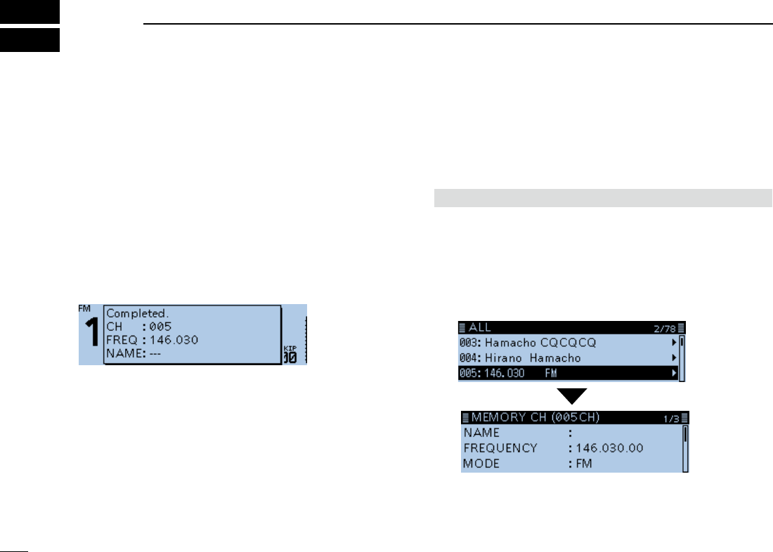
New2001
1
New2001New2001
MEMORY OPERATION
5
ID-4100A/ID-4100E BASIC MANUALID-4100A/ID-4100E BASIC MANUAL
■Entering Memory channels
The Memory mode is useful to quickly select often-used
repeaters.
This section describes the basic channel content entry.
See the Operating Guide on the Icom website for details.
Example: Entering 146.030 MHz/FM mode into a blank
channel.
Hold down [MW] for 1 second.
• The memory contents are briey displayed, then the operating
data is saved into a blank channel.
■Checking the Memory contents
You can check the Memory contents on the MEMORY LIST
screen.
Example: Checking the contents of Memory channel 5.
Manage Memory > Memory CH
1. Push [MENU].
2. Select “Manage Memory,” then push [ï].
3. Select “Memory CH,” then push [ï].
• Displays the MEMORY CH screen.
4. Select “ALL,” then push [ï].
• Displays the ALL screen.
5. Select “005,” then push [ï].
• Displays the data in Channel 5 on the MEMORY CH (005CH)
screen.
LYou can select a page by rotating [DIAL].
6. Push [MENU].
• Returns to the standby screen.

2
5
MEMORY OPERATION
New2001
5
ID-4100A/ID-4100E BASIC MANUAL
New2001
■Selecting a Memory channel
In the Memory mode, you can select the Memory channels
by rotating [DIAL].
1. Push [V/M] several times until you enter the Memory
mode.
Displayed
L Pushing [V/M] toggles between the VFO and Memory
modes.
2. Rotate [DIAL].
• Selects a Memory channel.

New2001
1
New2001New2001
SCAN OPERATION
6
ID-4100A/ID-4100E BASIC MANUALID-4100A/ID-4100E BASIC MANUAL
■VFO mode scan
1. Push [V/M] several times until you enter the VFO mode.
2. Hold down [BAND] for 1 second.
• Opens the Scan Type Select window.
L If you hold down [BAND] for 3 seconds, the last selected
scan starts.
3. Rotate [DIAL] to select a scan type, then push [ï].
• The scan starts.
LThe decimal point and the selected scan type icon blink.
L When receiving a signal, the S-meter displays the received
signal strength.
4. Push [BAND].
• Cancels the scan.
DScan type
The VFO mode scan has 6 scan types.
• ALL: Full scan
• BAND: Band scan
• P-LINK0 ~ 9: Program link scan
• P00 ~ 24: Program scan
• DUP: Duplex scan
(Displayed only when duplex is set.)
• TONE: Tone scan
(For the Tone Squelch scanning)
L The frequencies that are set as a Skip channel (PSKIP)
are skipped during a scan. (p. ??)
L When the “Program Skip” item is set to “OFF,” the Skip
channel frequencies are not skipped. (p. ??)
(Scan > Program Skip)
Scanning is a versatile function that can automatically
search for signals. A scan makes it easier to locate stations
to contact or listen to, or to skip unwanted channels or
frequencies.
This section describes the basic scan operation.
See the Operating Guide on the Icom website for details.
TIP:
• During a scan, rotating [DIAL] switches the scanning
direction.
• During a scan, you can change the operating band,
tuning step, and so on, on the Quick Menu window.
• The scan continuously runs, even if you push [MENU] or
[QUICK] during a scan.

2
6
SCAN OPERATION
New2001
6
ID-4100A/ID-4100E BASIC MANUAL
New2001
DSetting the skip frequencies
You can set unnecessary frequencies as a Skip channel
(PSKIP) to be skipped during a scan. The Skip function
speeds up a scan.
1. Start the VFO scan.
• When a signal is received, the scan pauses.
2. Hold down [MW] for 1 second.
• Sets the frequency as a Skip channel into empty Memory
channel 999.
• The entered Memory channel number blinks.
L If channel 999 already has content, the transceiver
automatically searches for another blank channel to use.
If there is no blank channel, a beep sounds, and the
frequency is not set as a Skip channel.
3. After setting, the scan resumes.
TIP: Once frequencies are set as a Skip channel, these
frequencies are skipped until clearing the skip setting. To
clear the skip setting, see page ?? for details.
L The skip setting is also cleared when the Memory
channel set as a Skip channel is deleted. See the
Operating Guide on the Icom website for details.
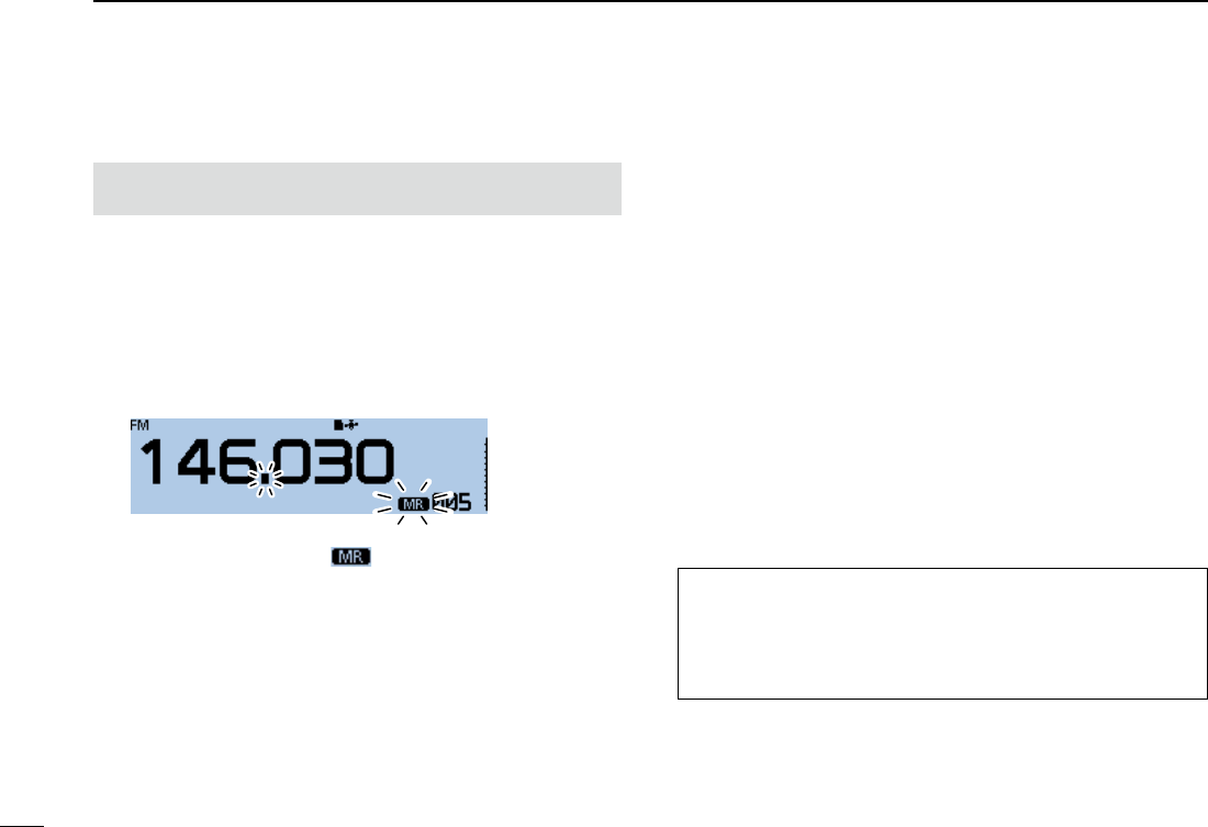
3
6SCAN OPERATION
New2001 New2001
ID-4100A/ID-4100E BASIC MANUAL
■Memory scan
NOTE: Two or more memory channels, which are not set
as Skip channels, must be entered to start a Memory scan.
1. Push [V/M] several times until you enter the Memory
mode.
2. Hold down [BAND] for 1 second.
• Opens the Scan Type Select window.
L If you hold down [BAND] for 3 seconds, the last selected
scan starts.
3. Rotate [DIAL] to select a scan type, then push [ï].
• The scan starts.
LThe decimal point and blink.
L When receiving a signal, the S-meter displays the received
signal strength.
4. Push [BAND].
• Cancels the scan
DScan type
The Memory mode scan has 6 scan types.
• ALL: Full scan
• BAND: Band Memory scan
• MODE: Mode Memory scan
• DUP: Duplex scan
(Displayed only when duplex is set.)
• TONE: Tone scan
(For the Tone squelch scanning)
L The channels that are set as a Skip channel (PSKIP or
SKIP) are skipped during a scan. (p. ??)
L When two or more Memory channels, which are not set
as Skip channels, are entered in a bank, the Memory
bank scan is usable. See the Operating Guide on the
Icom website for details.
TIP:
• During a scan, rotating [DIAL] switches the scanning
direction.
• The scan continuously runs, even if you push [MENU] or
[QUICK] during a scan.

4
6
SCAN OPERATION
New2001
6
ID-4100A/ID-4100E BASIC MANUAL
You can set or clear a Skip channel setting.
The channels that are set as a Skip channel are skipped
during a scan. (p. ??)
1. Push [V/M] several times until you enter the Memory
mode.
2. Rotate [DIAL] to select the Memory channel.
3. Push [QUICK].
4. Rotate [DIAL] to select “SKIP,” then push [ï].
5. Select the option, then push [ï].
• OFF: Cancel the skip setting.
• SKIP: Skipped during a memory scan.
• PSKIP: Skipped during both VFO and memory scans.
• When a Skip channel is set, “SKIP” or “PSKIP” is displayed.
■Setting and clearing a Skip channel

New2001
1
New2001New2001
RECORDING A QSO ONTO A microSD CARD
6
ID-4100A/ID-4100E BASIC MANUAL
■About the microSD card
NOTE: The microSD and microSDHC cards are not
supplied. (user supplied)
A microSD card of up to 2 GB, or an microSDHC of up to 32
GB, can be used with the ID-4100A/E.
Icom has checked the compatibility with the following
microSD and microSDHC cards.
(As of April 2017)
Brand Type Memory size
SanDisk®microSD 2 GB
microSDHC 4/8/16/32 GB
InformationL
• The performance of the cards listed above is not
guaranteed.
• Throughout the rest of this document, the microSD card
and an microSDHC card are simply called microSD cards.
• Icom recommends that you format all microSD cards to
be used with the transceiver, even preformatted microSD
cards for PCs or other uses. (p. ??)
NOTE:
• Before using the microSD card, read the instructions of
the microSD card thoroughly.
• If you do any of the following, the microSD card data may
be corrupted or deleted.
- You remove the microSD card from the transceiver
while accessing the microSD card.
- You change the external power supply’s voltage while
accessing the microSD card.
- You start the vehicle engine while accessing the
microSD card.
• Do not touch the contacts of the microSD card.
• The transceiver takes a longer time to recognize a high
capacity microSD card.
• The microSD card will get warm if used continuously for a
long period of time.
• The microSD card has a certain lifetime, so data reading
or writing may not be possible after using it for a long
time period.
• When reading or writing data is impossible, the microSD
card’s lifetime has ended. In this case, purchase a new
one. We recommend you make a backup le of the
important data onto your PC.
• Icom will not be responsible for any damage caused by
data corruption of an microSD card.
TIP: Saving the factory default data is recommended. To
save data, insert the card into the transceiver’s slot, then
select the “SD Card” item on the MENU screen.
(MENU > SD Card > Save Setting)
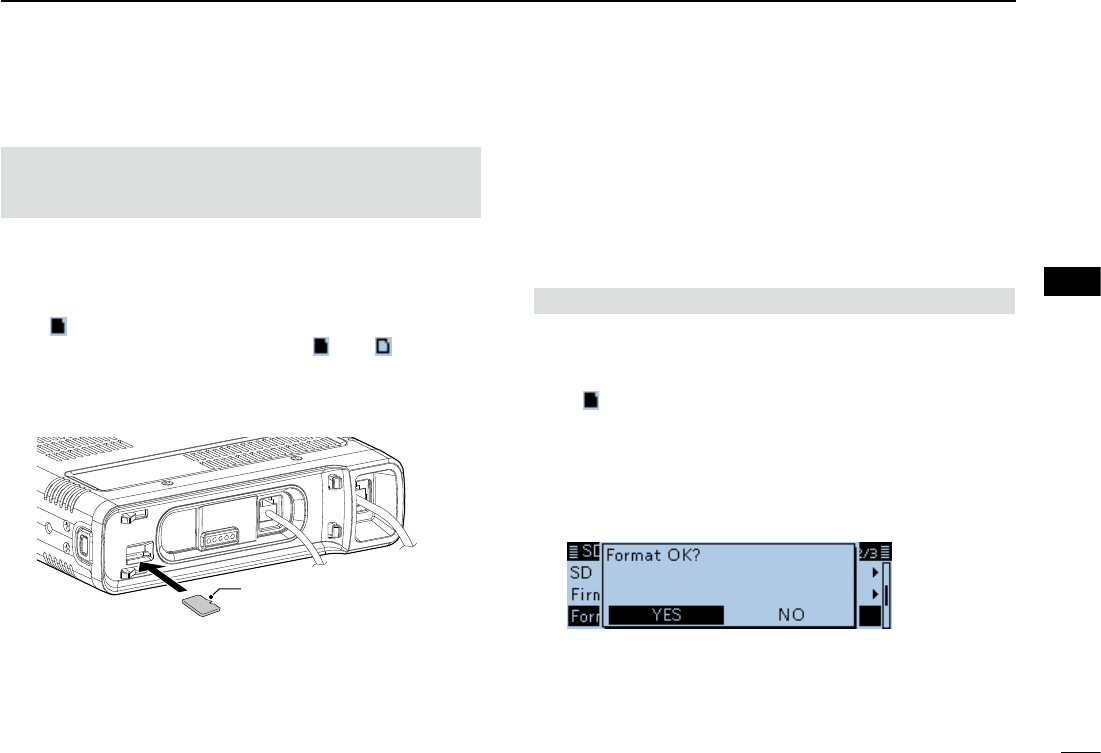
2
6
RECORDING A QSO ONTO A microSD CARD
New2001
1
2
3
4
5
6
7
8
9
10
11
12
13
14
15
16
17
18
19
ID-4100A/ID-4100E BASIC MANUAL
New2001
■Inserting the microSD card
NOTE: Before inserting, be sure to check the card
direction. If the card is forcibly or inversely inserted, it will
damage the card and/or the slot.
1. Turn OFF the transceiver.
2. Insert the card into the slot until it locks in place, and
makes a ‘click’ sound.
3. Turn ON the transceiver.
• “ ” is displayed when the microSD card is inserted.
L While accessing the microSD card, “ ” and “ ” alternately
blink.
Terminals
facing down
DFormatting the microSD card
When you use a brand new microSD card, format it by doing
the following steps.
L Formatting a card erases all its data. Before formatting
any used card, back up its data onto your PC.
SD Card > Format
1. Turn OFF the transceiver, then insert the card into the
slot.
2. Turn ON the transceiver.
• “ ” is displayed.
3. Push [MENU].
4. Rotate [DIAL] to select “SD Card,” then push [ï].
• SD CARD screen is displayed.
5. Select “Format,” then push [ï].
• The conrmation dialog “Format OK?” is displayed.
6. Select “YES,” then push [ï].
• The formatting starts and the display shows the formatting
progress.
L After formatting ends, the display automatically returns to
the screen displayed before the “Format OK?” window.
Front panel
(Main unit)
microSD card
Cut corner side
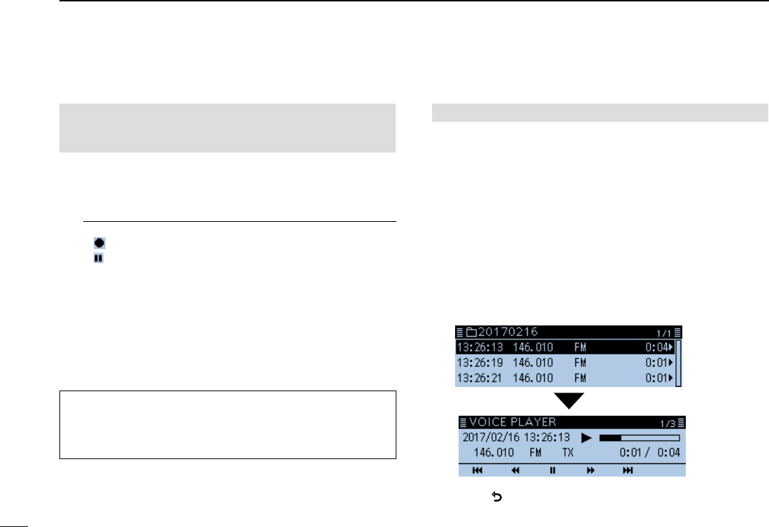
3
6RECORDING A QSO ONTO A microSD CARD
New2001 New2001
ID-4100A/ID-4100E BASIC MANUAL
■Recording a QSO audio
NOTE: Once the voice recording starts, it will continue
until you stop recording, even if you turn OFF the
transceiver.
1. Push [QUICK].
2. Rotate [DIAL] to select “<<REC Start>>,” then push [ï].
• “Recording started” is briey displayed, and voice recording
starts.
InformationL
• “ ” is displayed while the transceiver is recording.
• “ ” is displayed while the recording is paused.
• Recording is continuous until you manually stop recording, or
the card becomes full.
• If the recording le’s content reaches 2GB, the transceiver
automatically creates a new le, and continues recording.
3. Push [QUICK].
4. Select “<<REC Stop>>,” then push [ï].
• “Recording stopped” is briey displayed, and voice recording
stops.
TIP: When the PTT Automatic Recording function is ON,
the recording automatically starts when [PTT] is pushed.
( MENU > Voice Memo > QSO Recorder > Recorder Set >
PTT Auto REC)
■Playing recorded audio
Voice Memo > QSO Recorder > Play Files
1. Push [MENU].
2. Rotate [DIAL] to select “Voice Memo,” then push [ï].
• VOICE MEMO screen is displayed.
3. Select “QSO Recorder,” then push [ï].
• QSO RECORDER screen is displayed.
4. Select “Play Files,” then push [ï].
• PLAY FILES screen is displayed.
5. Select the folder that contains the file you want to play.
• The le list is displayed.
L The folder is named yyyymmdd (y: year, m: month, d: day.)
6. Select the file that you want to play.
• VOICE PLAYER screen is displayed, and the le starts to
play.
7. Push [].
• Stops the playing, then the VOICE PLAYER screen closes.
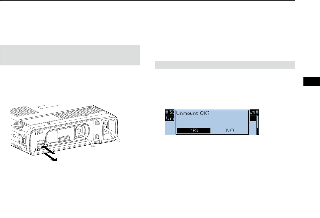
4
6
RECORDING A QSO ONTO A microSD CARD
New2001
1
2
3
4
5
6
7
8
9
10
11
12
13
14
15
16
17
18
19
ID-4100A/ID-4100E BASIC MANUAL
■Removing the microSD card
q Push
w Pull out
D Removing the microSD card while the
transceiver’s power is ON
SD Card > Unmount
1. Push [MENU].
2. Rotate [DIAL] to select “SD Card,” then push [ï].
• SD CARD screen is displayed.
3. Select “Unmount,” then push [ï].
• The conrmation dialog “Unmount OK?” is displayed.
4. Select “YES,” then push [ï].
• When the unmounting is completed, “Unmount is completed.”
is briey displayed, then the display automatically returns to
the screen displayed before the “Unmount OK?” window.
5. Push in the microSD card until a click sounds, and then
carefully pull it out.
DRemoving the microSD card
1. Turn OFF the power.
2. Push in the microSD card until a click sounds, and then
carefully pull it out.
Front panel
(Main unit)
NOTE: DO NOT remove the card from the transceiver
while the card is being accessed. Otherwise, the card data
may be corrupted or deleted.
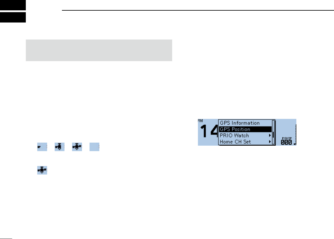
New2001
1
New2001New2001
GPS OPERATION
7
ID-4100A/ID-4100E BASIC MANUALID-4100A/ID-4100E BASIC MANUAL
■GPS operation
The transceiver has a built-in GPS receiver. You can check
your current position, and transmit GPS data in the DV
mode.
See the Operating Guide on the Icom website for details.
DGPS receive setting
Conrm the GPS receiver is receiving your position.
The GPS icon blinks when searching for satellites.
➪ ➪ ➪
The GPS icon stops blinking when the minimum needed
number of satellites is found.
L It may take only a few seconds to receive, or it may take a few
minutes, depending on your operating environment. If you have
difculties receiving, we recommend that you try a different
location.
L When the “GPS Select” item is set to “Manual,” the icon does not
appear.
(MENU > GPS > GPS Set > GPS Select)
NOTE: The built-in GPS receiver cannot calculate its
position if it cannot receive signals from the GPS satellites.
Refer to page ?? for details.
■Checking your GPS position
You can check your current position.
If you transmit while displaying the GPS position screen, the
screen closes.
But you can check your current position, RX position, and so
on by touching the GPS icon while transmitting.
DDisplaying Position Data
1. Push [QUICK].
2. Select “GPS Position,” then push [ï].
• Displays the GPS POSITION screen.
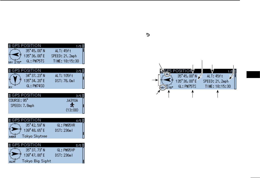
2
7
GPS OPERATION
New2001
7
ID-4100A/ID-4100E BASIC MANUAL
New2001
About the GPS POSITION screen
GPS memory
position
screen
Received
position
screen 1
My position
screen
GPS alarm
position
screen
3. Rotate [DIAL].
• Selects the page.
4. Push [].
• Returns to the standby screen.
Received
position
screen 2
GPS POSITION screen (MY)
Latitude
Time
Compass direction
top is North.
Your course
heading is
East.
Your course
direction is
275° degrees.
Shows My
position
Altitude
Grid locator
Speed
Longitude
(Example)
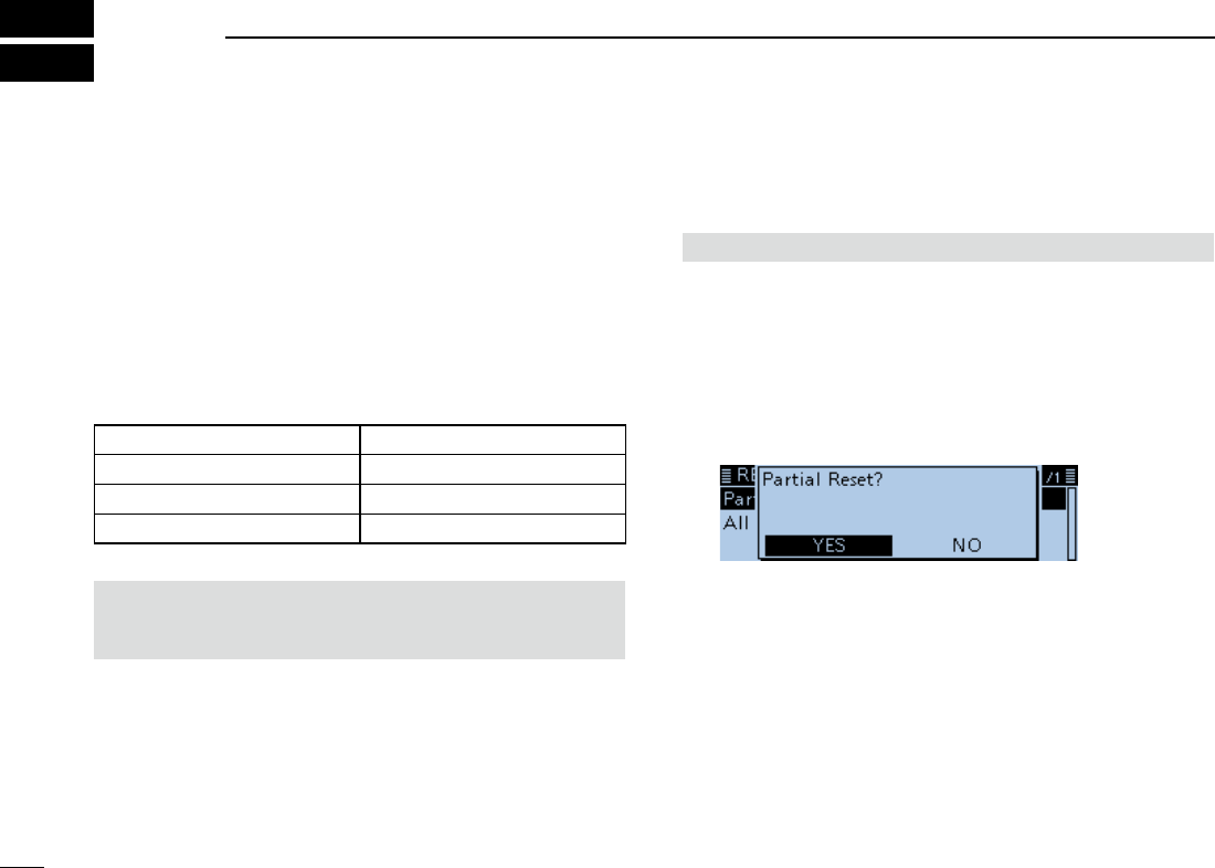
New2001
1
New2001New2001
MAINTENANCE
8
ID-4100A/ID-4100E BASIC MANUALID-4100A/ID-4100E BASIC MANUAL
■Resetting
Occasionally, erroneous information will be displayed when,
for example, rst applying power. This may be caused
externally by static electricity or by other factors. If this
problem occurs, turn OFF the transceiver. After waiting a
few seconds, turn ON the transceiver again. If the problem
is still there, perform a Partial reset or an All reset.
A Partial reset resets the operating settings to their default
values (VFO frequency, VFO settings, menu contents)
without clearing data as listed below:
Memory channel contents Scan Edge contents
Call channel contents Call sign memories
Message data DTMF memory contents
GPS Memory contents Repeater list
BE CAREFUL! An All reset clears all programming and
returns all settings to their factory defaults. See the
Operating Guide on the Icom web site for details.
DPartial Reset
Others > Reset > Partial Reset
1. Push [MENU].
2. Rotate [DIAL] to select “Others,” then push [ï].
• OTHERS screen is displayed.
3. Select “Reset,” then push [ï].
• RESET screen is displayed.
4. Select “Partial Reset,” then push [ï].
• The conrmation dialog “Partial Reset?” is displayed.
5. Select “YES,” then push [ï].
• When the partial reset is completed, “PARTIAL RESET” is
displayed, then the display automatically returns to the default
screen.
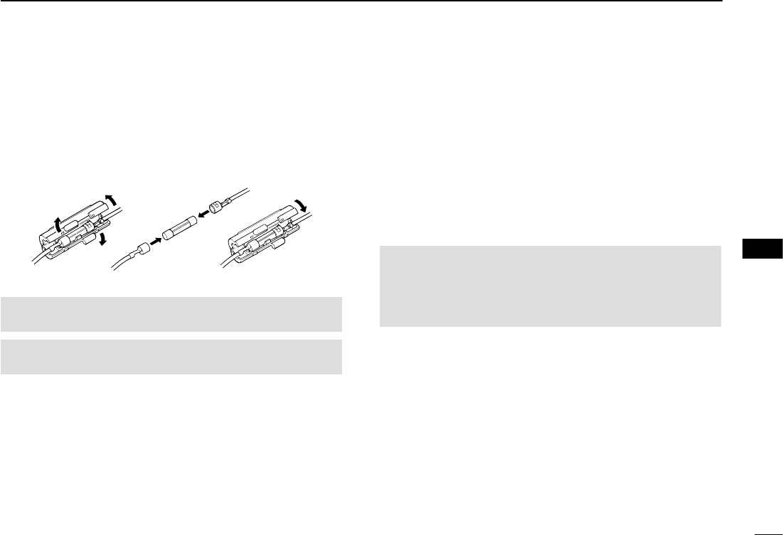
2
8
MAINTENANCE
New2001
8
ID-4100A/ID-4100E BASIC MANUAL
New2001
■Fuse replacement
A fuse is installed in each fuse holder of the supplied DC
power cable. If a fuse blows, or the transceiver stops
functioning, track down the source of the problem if
possible, repair it and then replace the damaged fuse with a
new rated one (FGB 15 A).
R WARNING! NEVER remove the fuse holders from the
DC power cable. USE only the applicable fuses.
NOTE: Before replacing the fuse, be sure to disconnect
the DC cable from the power supply.
■Power protect function
The transceiver is equipped with a protection circuit for the
power amplifier. The circuit activates when the transceiver
continuously transmit at high power, and then temperature
becomes extremely high.
In this case, the transceiver automatically reduces transmit
output power to low (approximately 5 W).
When the Power Protect function activates, wait until the
transceiver’s temperature returns to normal.
NOTE: When the power supply voltage is over 17.0 V, the
transceiver automatically displays “Over Voltage,” and then
sounds a warning beep. In this case, the transceiver may
be damaged, and contact your nearest Icom Dealer or
Service Center.

3
8MAINTENANCE
New2001 New2001
ID-4100A/ID-4100E BASIC MANUAL
■Troubleshooting
To communicate through the repeater, your signal must access to the repeater. When your signal accesses your local repeater,
but it is not sent to the destination repeater, the repeater replies with an status message.
PROBLEM POSSIBLE CAUSE SOLUTION REF.
Transceiver does not
turn ON.
• The power cable is improperly connected.
• A fuse is blown.
• Power source voltage is not correct.
• Reconnect the DC power cable correctly.
• Correct the cause, then replace the fuse
with an equivalent fuse. (Fuses are installed
in the DC power cable and in the internal
PA unit.)
• Apply the correct 13.8 V DC.
p. ??
p. ??
p. ??
No sound comes from
the speaker.
• The audio volume level is too low.
• The squelch is closed.
• The tone squelch is ON in the FM mode.
• The external speaker is not connected.
• The audio is muted.
• Rotate [VOL] clockwise to obtain a suitable
listening level.
• Rotate [SQL] to 12 o’clock position to open
the squelch.
• Turn OFF the Tone squelch.
• Correct the cause, then reconnect.
• Hold down [MUTE] to release mute.
p. ??
Sensitivity is too low,
and only strong signals
are audible.
• The antenna is defective or the coaxial
cable connector is shorted or cut.
• The Attenuator function is turned ON.
• The squelch is set too tight.
• Reconnect to the antenna connector.
• Turn OFF the attenuator.
• Rotate [SQL] to adjust the squelch level.
p. ??

4
8
MAINTENANCE
New2001
8
ID-4100A/ID-4100E BASIC MANUAL
PROBLEM POSSIBLE CAUSE SOLUTION REF.
Transmitting is
impossible.
• Duplex function are ON, and the transmit
and receive frequencies are different.
• The transmit power level is set to LOW or
MID.
• The PTT Lock function is activated.
• The Busy Lockout function is activated.
• Turn OFF the Duplex function.
• Set the transmit power level to HIGH.
• Turn OFF the PTT Lock function.
• Turn OFF the Busy Lockout function.
p. ??
The displayed
frequency is
erroneous.
• The CPU has malfunctioned.
• External factors have caused the fault.
• Reset the transceiver.
• Disconnect and connect to the DC power
supply.
p. ??
p. ??
Frequency cannot be
set.
• The Lock function is activated.
• The VFO mode is not selected.
• Hold down [LOCK] for 1 second to turn OFF
the Lock function.
• Push [V/M] to select the VFO mode.
p. ??
A Program Scan does
not start.
• The VFO mode is not selected.
• The same frequencies are entered into the
scan edges.
• Push [V/M] to select the VFO mode.
• Enter different frequencies into the scan
edges.
p. ??
A Memory Scan does
not start.
• The Memory mode is not selected.
• Only one or no memory channel has been
programmed.
• Push [V/M] to select the Memory mode.
• Program two or more memory channels.
p. ??
During tone squelch
operation, the received
audio breaks off at the
other station.
• Transmitter’s microphone gain is too high. • Set the microphone sensitivity to low.
• Turn ON the ALC function.
p. ??
Transmission is
automatically cut off.
• The Time-out timer function is activated. • Turn OFF the Time-out timer function.
p. ??

New2001
1
New2001New2001
SPECIFICATIONS
9
ID-4100A/ID-4100E BASIC MANUALID-4100A/ID-4100E BASIC MANUALID-4100A/ID-4100E BASIC MANUAL
DGeneral
• Frequency coverage:
EUR RX 118 ~ 174 MHz*1, 230 ~ 550 MHz*2
TX 144 ~ 146 MHz, 430 ~ 440 MHz
ITR
RX 144 ~ 146 MHz, 430 ~ 434 MHz,
435 ~ 438 MHz
TX 144 ~ 146 MHz, 430 ~ 434 MHz,
435 ~ 438 MHz
USA RX 118 ~ 174 MHz*3, 230 ~ 550 MHz*4
TX 144 ~ 148 MHz, 430 ~ 450 MHz
EXP RX 118 ~ 174 MHz*3, 230 ~ 550 MHz*2
TX 137 ~ 174 MHz*3, 400 ~ 470 MHz*2
*1 Guaranteed only 144 ~ 146 MHz
*2 Guaranteed only 430 ~ 440 MHz
*3 Guaranteed only 144 ~ 148 MHz
*4 Guaranteed only 430 ~ 450 MHz
*6 Guaranteed only 400 ~ 470 MHz
• Mode: F2D/F3E (FM/FM-N), F7W
(DV),
A3E (AM/AM-N) RX only
• No. of memory channels: 1000 channels
• No. of program scan channels:
25 channels
( 2 edge frequencies in each
channel)
• No. of call channels: 4 channels
(2 channels × 2 bands)
• No. of repeater lists: 1,500
• No. of GPS memory: 300
• Antenna impedance: 50 Ω (SO-239)
• Usable temperature range: –10˚C to +60˚C
(+14˚F to +140˚F)
• Frequency stability: ±2.5 ppm (–10˚C to +60˚C,
+14˚F to +140˚F)
• Digital transmission speed: 4.8 kbps
• Voice coding speed: 2.4 kbps
• Frequency resolution: 5 kHz, 6.25 kHz, 8.33 kHz*,
10 kHz, 12.5 kHz, 15 kHz,
20 kHz, 25 kHz, 30 kHz, and
50 kHz
* Selectable depending on the
operating band or mode.
• Power supply: 13.8 V DC ±15%
(negative ground)
• Current drain:
Transmit
Maximum current drain:
≤ 13.0 A
Receive
Standby: ≤ 0.9 A
Maximum audio: ≤ 1.2 A
• Dimensions:
150(W) × 40(H) × 171.9(D) mm
5.9(W) × 1.6(H) × 6.8(D) inch
(projections are not included)
• Weight (approximate): 1.2 kg, 2.6 lb
( microphone, cable, and
bracket are not included)

2
9
SPECIFICATIONS
New2001
9
New2001
ID-4100A/ID-4100E BASIC MANUAL
DTransmitter
• Modulation system:
FM/FM-N Variable reactance frequency
modulation
DV GMSK reactance frequency
modulation
• Max Deviation:
FM ≤ ±5.0 kHz
FM-N ≤ ±2.5 kHz
• Occupied bandwidth: Less than 6.0 kHz (DV)
• Microphone impedance: 600 Ω
• Spurious emission: ≤ –60 dBc
• Output power: High 50 W, Mid 15 W,
Low 5 W
DReceiver
• Receive system: Double Conversion
Superheterodyne system
• IF frequencies:
1st IF 46.35 MHz
2nd IF 450 kHz
• Sensitivity (except spurious points)
Amateur bands
FM/FM-N (12 dB SINAD)
≤ 0.18 μV
DV (BER 1%)
≤ 0.22 μV
Except Amateur bands
FM/FM-N (12 dB SINAD)
≤ 0.32 μV (137.000 to 159.995 MHz)
≤ 0.32 μV (160.000 to 174.000 MHz)
≤ 1.8 μV (230.000 to 259.000 MHz)
≤ 0.56 μV (260.000 to 321.995 MHz)
≤ 0.56 μV (322.000 to 374.995 MHz)
≤ 0.56 μV (375.000 to 399.995 MHz)
≤ 0.32 μV (400.000 to 499.995 MHz)
≤ 0.56 μV (500.000 to 550.000 MHz)
AM/AM-N (10 dB S/N)
≤ 1 μV (118.000 to 136.991 MHz)
≤ 5.6 μV (230.000 to 259.000 MHz)
≤ 1.8 μV (260.000 to 321.995 MHz)
≤ 1.8 μV (322.000 to 374.995 MHz)
• Squelch sensitivity: ≤ 0.13 μV (Threshold)
• Selectivity:
FM ≥ 60 dB
FM-N ≥ 55 dB
DV ≥ 50 dB
• Spurious and image rejection ratio:
≥ 60 dB
• AF output power: ≥ 2.0 W (at 10% distortion with
an 8 Ω load)
• AF output impedance: 8 Ω
New2001
1
New2001New2001
INFORMATION
10
ID-4100A/ID-4100E BASIC MANUALID-4100A/ID-4100E BASIC MANUAL
■COUNTRY CODE LIST
• ISO 3166-1
Country Codes Country Codes
1
2
3
4
5
6
7
8
9
10
11
12
13
14
15
16
17
Austria
Belgium
Bulgaria
Croatia
Czech Republic
Cyprus
Denmark
Estonia
Finland
France
Germany
Greece
Hungary
Iceland
Ireland
Italy
Latvia
AT
BE
BG
HR
CZ
CY
DK
EE
FI
FR
DE
GR
HU
IS
IE
IT
LV
18
19
20
21
22
23
24
25
26
27
28
29
30
31
32
33
Liechtenstein
Lithuania
Luxembourg
Malta
Netherlands
Norway
Poland
Portugal
Romania
Slovakia
Slovenia
Spain
Sweden
Switzerland
Turkey
United Kingdom
LI
LT
LU
MT
NL
NO
PL
PT
RO
SK
SI
ES
SE
CH
TR
GB
■DISPOSAL
The crossed-out wheeled-bin symbol on your
product, literature, or packaging reminds you
that in the European Union, all electrical and
electronic products, batteries, and accumulators
(rechargeable batteries) must be taken to
designated collection locations at the end of
their working life. Do not dispose of these
products as unsorted municipal waste.
Dispose of them according to the laws in your
area.

2
10
INFORMATION
New2001
10
ID-4100A/ID-4100E BASIC MANUAL
New2001
■FCC INFORMATION
• FOR CLASS B UNINTENTIONAL RADIATORS:
This equipment has been tested and found to comply with
the limits for a Class B digital device, pursuant to part 15
of the FCC Rules. These limits are designed to provide
reasonable protection against harmful interference in a
residential installation. This equipment generates, uses
and can radiate radio frequency energy and, if not installed
and used in accordance with the instructions, may cause
harmful interference to radio communications. However,
there is no guarantee that interference will not occur in a
particular installation. If this equipment does cause harmful
interference to radio or television reception, which can be
determined by turning the equipment off and on, the user is
encouraged to try to correct the interference by one or more
of the following measures:
• Reorient or relocate the receiving antenna.
• Increase the separation between the equipment and
receiver.
• Connect the equipment into an outlet on a circuit
different from that to which the receiver is connected.
• Consult the dealer or an experienced radio/TV
technician for help.
CAUTION: Changes or modifications to this device, not
expressly approved by Icom Inc., could void your authority
to operate this device under FCC regulations.

New2001
1
New2001New2001
Chapter
11
ID-4100A/ID-4100E BASIC MANUALID-4100A/ID-4100E BASIC MANUAL

2
11
CHAPTER CONTINUED
New2001
1
2
3
4
5
6
7
8
9
10
11
12
13
14
15
16
17
18
19
ID-4100A/ID-4100E BASIC MANUAL
New2001

New2001
1
New2001New2001
MENU ITEM LIST
ID-4100A/ID-4100E BASIC MANUALID-4100A/ID-4100E BASIC MANUAL
DUP/TONE... Offset Freq
Repeater Tone
TSQL Freq
Tone Burst
DTCS Code
DTCS Polarity
Digital Code
Manage Memory Memory CH
Call CH
Scan Pause Timer
Resume Timer
Temporary Skip Timer
Program Skip
Bank Link
Program Scan Edge
Program Link
Voice Memo QSO Recorder
Player Set
DV Auto Reply
Voice TX Record
TX Set
<<TX>>
GPS GPS Set
GPS TX Mode
GPS Information
GPS Position
GPS Memory
GPS Alarm
GPS Logger
GPS Auto TX
Call Sign —
RX History —
DV Memory Your Call Sign
Repeater List
My Station My Call Sign
TX Message
DV Set Tone Control
Auto Reply
DV Data TX
DV Fast Data
Digital Monitor
Digital Repeater Set
DV Auto Detect
RX Record (RPT)
BK
EMR
EMR AF Level
SPEECH RX Call Sign SPEECH
RX>CS SPEECH
DIAL SPEECH
MODE SPEECH
SPEECH Language
Alphabet
SPEECH Speed
SPEECH Level
DTMF/T-CALL DTMF Memory
DTMF Speed
QSO/RX Log QSO Log
RX History Log
CSV Format
The rst tree level of each Menu category are listed below.

2
MENU ITEM LIST
New2001
ID-4100A/ID-4100E BASIC MANUAL
New2001
Function Squelch/ATT Select
Squelch Delay
Fan Control
Dial Speed-UP
Auto Repeater
Remote MIC Key
Up/Down MIC Key
One-Touch PTT(Remote MIC)
PTT Lock
Busy Lockout
Time-Out Timer
Active Band
MIC Gain
Data Speed
CI-V
Power OFF (With No Controller)
Display LCD Backlight Brightness
LCD Backlight Color
Key Backlight Brightness
Key Backlight Color
Backlight Night Time Setting
Auto Dimmer Setting
LCD Contrast
RX Call Sign
RX Position Indicator
RX Position Display
RX Position Display Timer
Reply Position Display
TX Call Sign
Scroll Speed
Opening Message
Voltage (Power ON)
Display Unit
Display Language
System Language
Sounds Beep Level
Key-Touch Beep
Home CH Beep
Band Edge Beep
Scan Stop Beep
Standby Beep
Scope AF Output
Time Set Date/Time
GPS Time Correct
UTC Offset
Auto Power OFF
DV Gateway <<Terminal Mode>>
<<Access Point Mode>>
SD Card Load Setting
Save Setting
Import/Export
CSV Format
SD Card Info
Firmware Update
Format
Unmount
Bluetooth Set Bluetooth
Auto Connect
Pairing/Connect
<<Pairing Reception>>
Headset Set
VOX
Icom Headset
Data Device Set
Bluetooth Device Information
Initialize Bluetooth Device
Others Information
Clone
Reset
1-1-32 Kamiminami, Hirano-ku, Osaka 547-0003, Japan
New2001
A-7367D-1EX
Printed in Japan
© 2017 Icom Inc.
<Intended Country of Use>
■ AT ■ BE ■ CY ■ CZ ■ DK ■ EE
■ FI ■ FR ■ DE ■ GR ■ HU ■ IE
■ IT ■ LV ■ LT ■ LU ■ MT ■ NL
■ PL ■ PT ■ SK ■ SI ■ ES ■ SE
■ GB ■ IS ■ LI ■ NO ■ CH ■ BG
■ RO ■ TR ■ HR
#12 EUR-01
<Intended Country of Use>
■ AT ■ BE ■ CY ■ CZ ■ DK ■ EE
■ FI ■ FR ■ DE ■ GR ■ HU ■ IE
■ IT ■ LV ■ LT ■ LU ■ MT ■ NL
■ PL ■ PT ■ SK ■ SI ■ ES ■ SE
■ GB ■ IS ■ LI ■ NO ■ CH ■ BG
■
RO
■
TR
■
HR
#13 ITR-01