ICOM orporated 388600 VHF Marine Transceiver User Manual
ICOM Incorporated VHF Marine Transceiver
UserManual.wiki
>
ICOM orporated
>
388600 User Manual
User Manual
Navigation menu
Upload a User Manual
Namespaces
Wiki Guide
HTML
PDF
Info
Views
User Manual
Discussion / Help
Navigation
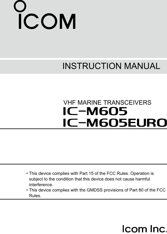
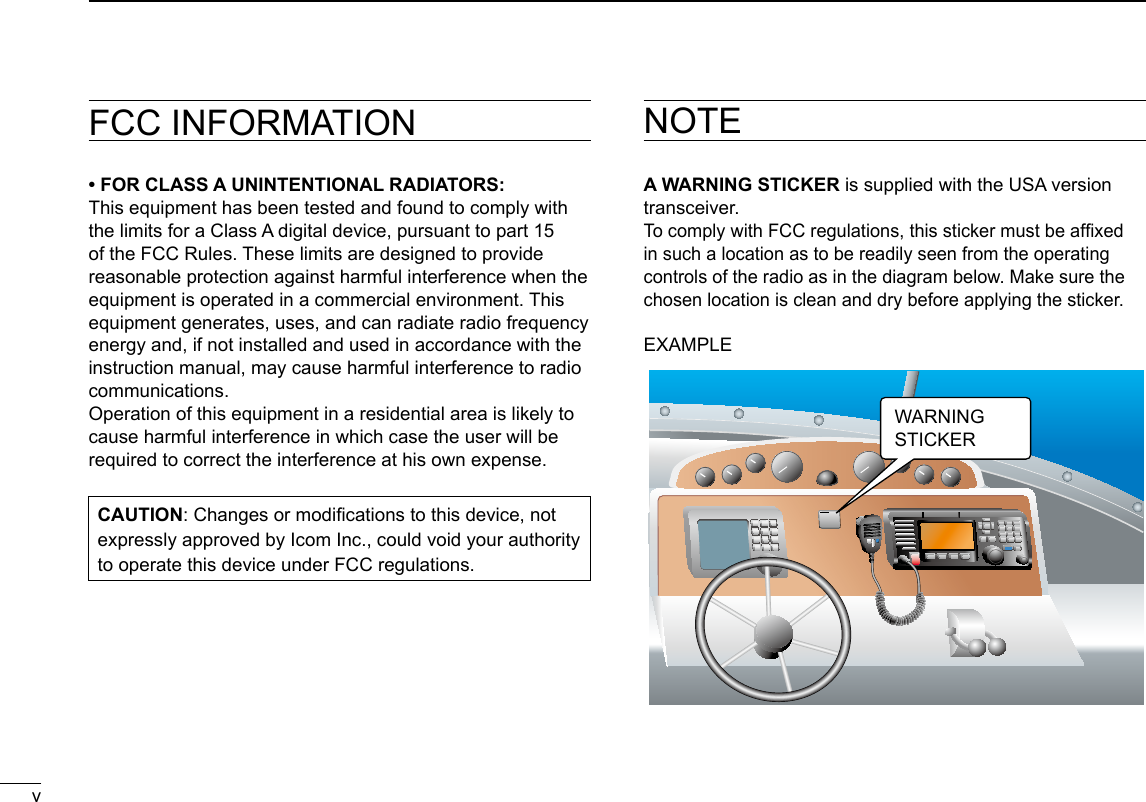
![IN CASE OF EMERGENCYIf your vessel requires assistance, contact other vessels and the Coast Guard by sending a Distress call on Channel 16.USING CHANNEL 16DISTRESS CALL PROCEDURE1. “MAYDAY MAYDAY MAYDAY.”2. “THIS IS ...............” (name of vessel).3. Say your call sign or other description of the vessel (AND 9 digit DSC ID if you have one).4. “LOCATED AT ...............” (your position).5. State the nature of the distress and assistance required.6. Give any other information which might facilitate the rescue.Or, transmit your Distress call using Digital Selective Calling on Channel 70.USING DIGITAL SELECTIVE CALLING (Ch 70)DISTRESS CALL PROCEDURE1. While lifting up the key cover, hold down [DISTRESS] for 3 seconds until you hear 3 short beeps and then one long beep.2. Wait for an acknowledgment on Channel 70 from a coast station. • After the acknowledgement is received, Channel 16 is automatically selected.3. Hold down [PTT], then transmit the appropriate information as listed above. iiINSTALLATION NOTEInstallation:The installation of this equipment should be made in such a manner as to respect the EC recommended electromagnetic eld exposure limits. (1999/519/EC)The maximum RF power available from this device is 25 watts. The antenna should be installed as high as possible for maximum efciency and the installation height should be at least 1.76 meters above any accessible position. In the case where an antenna cannot be installed at a reasonable height, then the transmitter should neither be continuously operated for long periods if any person is within a distance of 1.76 meters of the antenna, nor operated at all if any person is touching the antenna.It is recommended that antenna of a maximum gain of 3 dB is used. If higher gain antenna are required then please contact your Icom distributor for revised installation recommendations.Operation:The exposure to RF electromagnetic eld is only applicable when this device is transmitting. This exposure is naturally reduced due to the nature of alternating periods of receiving and transmitting. Keep your transmissions to the minimum necessary.](https://usermanual.wiki/ICOM-orporated/388600/User-Guide-3263423-Page-3.png)
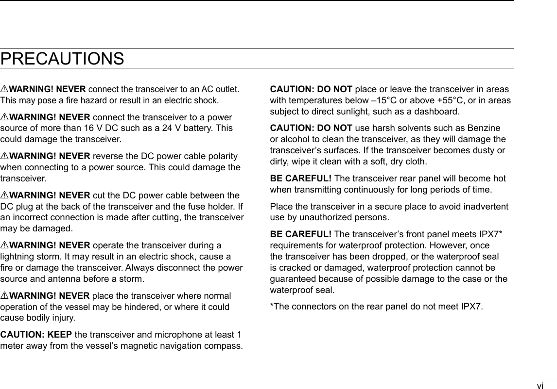
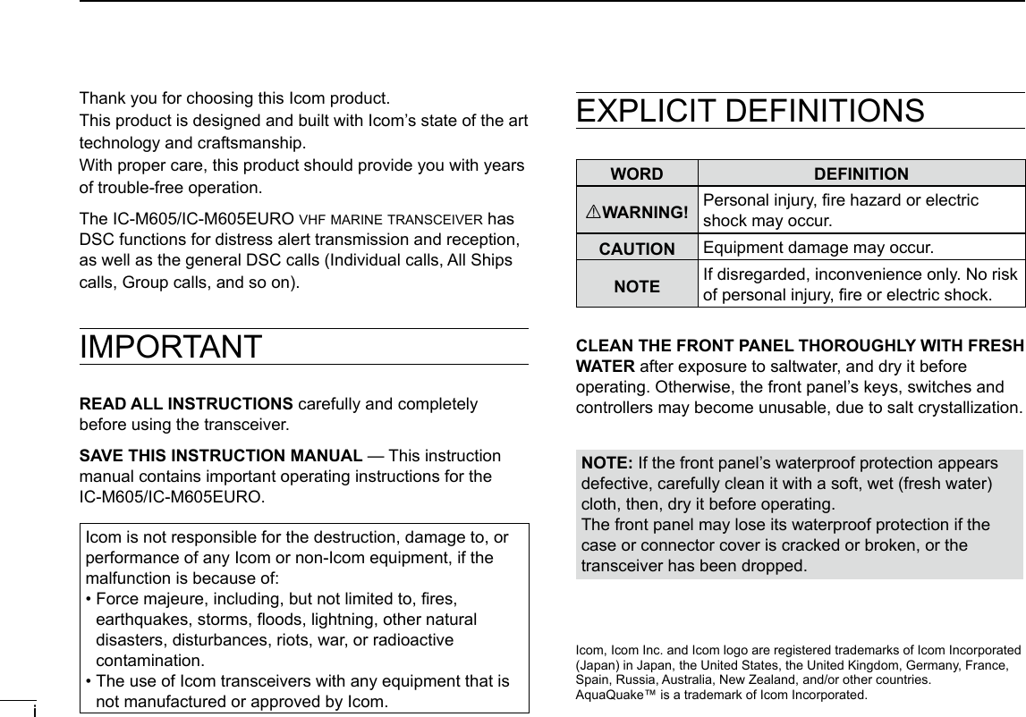
![viiiNew2001ACTION ICON DESCRIPTIONThe following describes the [CH/ENT], [ENT] and the keypad operations in this instruction manual. : Push [ENT] to enter or set.Push: Push the keypad to enter a digit or text.PushRotate: Rotate [CH/ENT] to select.Also, you can use the following key functions in the Menu screen.FUNCTION ACTIONSelect Rotate [CH/ENT].Push [∫] or [√].Enter Push [ENT], [CH/ENT], or [Enter] .Go to the next tree levelPush [ENT] or [≈].Go back to the previous tree levelPush [CLR], [Ω], or [Back] .Cancel Push [CLR].Exit Push [MENU] or [Exit] .](https://usermanual.wiki/ICOM-orporated/388600/User-Guide-3263423-Page-9.png)
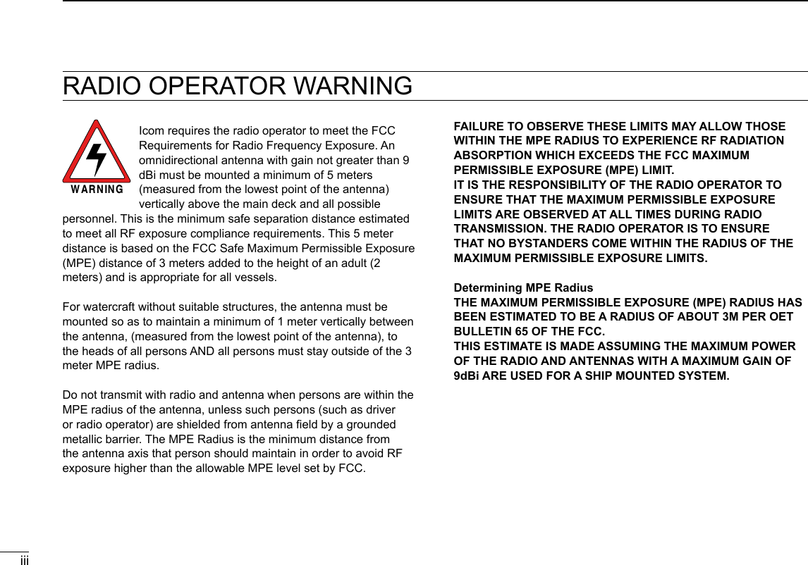
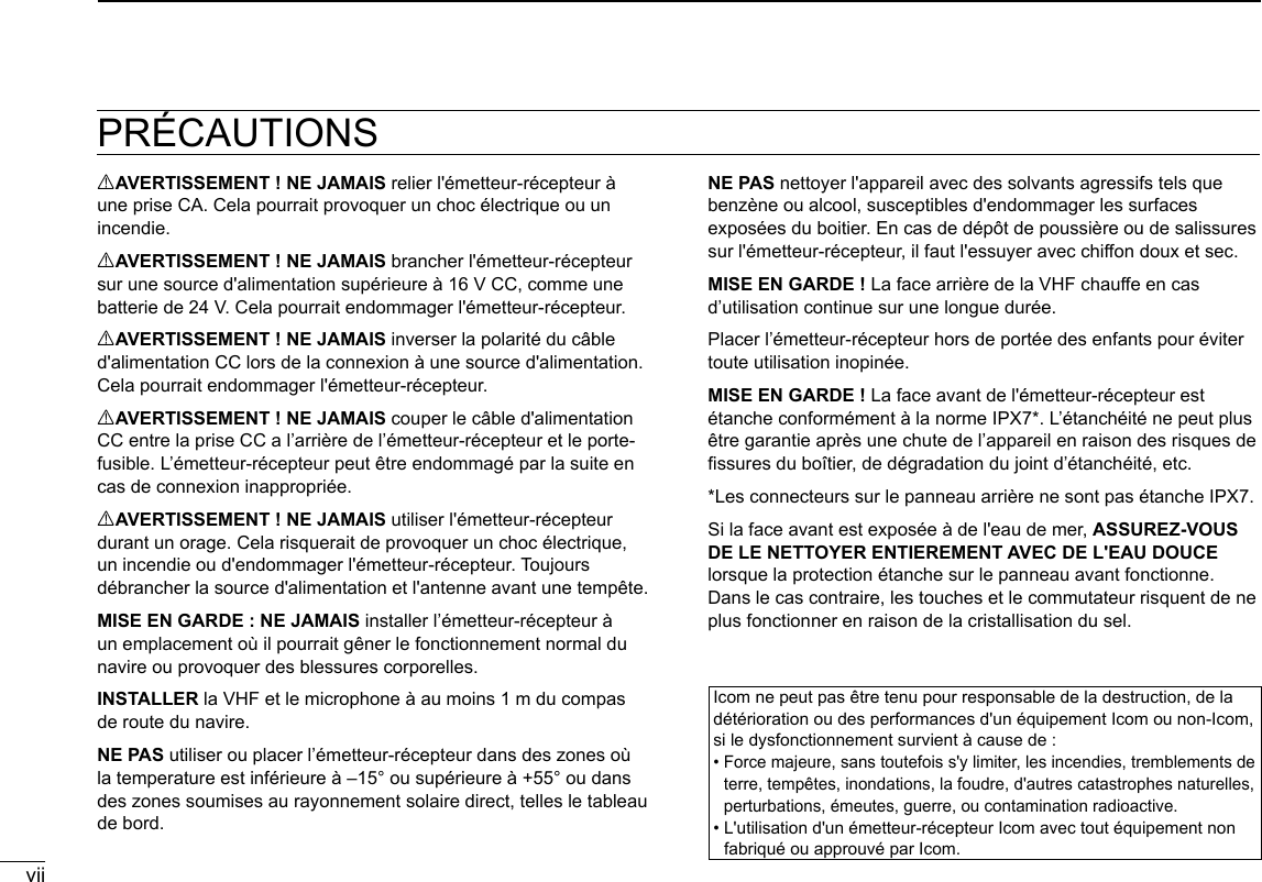
![New20012New2001PANEL DESCRIPTION2 ■Front panelq DISTRESS KEY [DISTRESS]!1 MENU KEY [MENU]Speaker Function display (p. ?)w ENTER KEY [ENT]e LEFT AND RIGHT KEYS [Ω]/[≈]r UP AND DOWN KEYS [∫]/[√]t KEYPADy POWER KEY [ ]u CHANNEL 16/ CALL CHANNEL KEY [16/C]i VOLUME/SQUELCH DIAL [VOL/SQL]o CLEAR KEY [CLR]!0 CHANNEL SELECTOR/ENTER SWITCH [CH/ENT]!2 SOFTWARE KEYSMIC CONNECTOR](https://usermanual.wiki/ICOM-orporated/388600/User-Guide-3263423-Page-12.png)
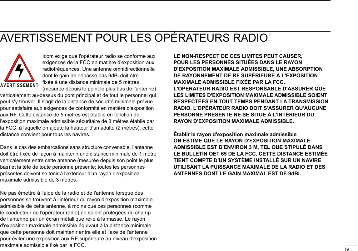
![New200132PANEL DESCRIPTIONNew200112345678910111213141516q DISTRESS KEY [DISTRESS] (p. ?) Hold down for 3 seconds to transmit a Distress call.w ENTER KEY [ENT] Push to set the entered data, selected item, and so on.e LEFT AND RIGHT KEYS [◄]/[►] z Push to scroll the Software Key functions. (p. ?) z In the character or number entry mode, push to select a character or number in the keypad. (p. ?)r UP AND DOWN/CHANNEL SELECT KEYS [▲]/[▼] z Push to select an operating channel (p. ?), Menu items (p. ?), Menu settings (p. ?), and so on. z While scanning, push to check the Favorite channels, change the scanning direction or manually resume a scan. (p. ?)t KEYPAD Push to enter numbers, letters or symbols. For channel number entry, see page ?. For channel name entry, see page ?.y POWER KEY [ ] Hold down for 1 second to turn the transceiver ON or OFF.u CHANNEL 16/CALL CHANNEL KEY [16/C] z Push to select Channel 16. (p. ?) z Hold down for 1 second to select the Call channel.(p. ?) • “CALL” is displayed when the Call channel is selected.i VOLUME/SQUELCH DIAL [VOL/SQL] (p. ?) z Rotate to adjust the volume level. z Push once or twice to display the Volume or Squelch Setting screen, and then rotate to adjust the volume or squelch level.o CLEAR KEY [CLR] Push to cancel the entered data, or to return to the previous screen.!0 CHANNEL SELECTOR/ENTER SWITCH [CH/ENT] z Rotate to select an operating channel (p. ?), Menu items (p. ?), or Menu settings (p. ?). z Push to set the entered data, or selected item. (p. ?)!1 MENU KEY [MENU] Push to enter or exit the Menu screen. (p. ?)](https://usermanual.wiki/ICOM-orporated/388600/User-Guide-3263423-Page-13.png)
![42PANEL DESCRIPTIONNew2001 New2001 ■Front panel (Continued)!2 SOFTWARE KEYS (p. ?) You can use various key functions that are assigned to the Software Keys, as described below. Compose Distress* (p. ?) Push to display the COMPOSE DISTRESS screen. Compose Others* (p. ?) Push to display the COMPOSE NON-DISTRESS screen. Task List (p. ?) When the transceiver has any task, push to enter the Task mode. Scan (p. ?) Push to start or stop a Normal or Priority scan. Dualwatch/Tri-watch [DW/TW] (p. ?) Push to start or stop the Dualwatch or Tri-watch. AIS (p. ?) Push to display the AIS plotter on the left side of the display. L An AIS receiver may not be installed, depending on the transceiver version. Channel/ Wheather [CH/WX] (p. ?) (For only the USA and AUS versions.) Push to select either the regular channels or the Weather channels. Channel [CHAN] (p. ?) (For only the versions except the USA and AUS versions. ) Push to enter the regular channel selection mode. High/Low [HI/LO] (p. ?) Push to set the output power level to high or low. LSome channels are set to only low power. Voice Scrambler (p. ?) Push to set the Voice Scrambler function. L This functions is displayed only when the voice scrambler unit is installed. RX Play (p. ?) Push to play recorded audio.* These key functions are not displayed in the Radio Telephone (RT) mode. (p. ?)](https://usermanual.wiki/ICOM-orporated/388600/User-Guide-3263423-Page-14.png)
![RX Hailer (p. ?) Push to turn the RX Hailer mode ON or OFF. LO/DX (p. ?) Push to turn the Attenuator function ON or OFF. LThe “LOC” icon appears when the Attenuator function is ON. Favorite channel [Favorite] (p. ?) z Push to set or clear the displayed channel as a Favorite channel. z Hold down for 3 seconds to clear or set all Favorite channels in the selected channel group. Channel Name (p. ?) Push to display the CHANNEL NAME screen. DSC Log (p. ?) Push to display the Received Call Log (RCVD CALL LOG) screen. Backlight (p. ?) Push to open the Backlight Settings window.New200152PANEL SCRIPTION12345678910111213141516 ■Software Key functionThe transceiver has Software Keys for various functions.The key function is displayed above the Software Key. DSelecting the Software Key function When “Ω” or “≈” is displayed beside the key icon, pushing [Ω] or [≈] scrolls the Software Key functions.When you push [Ω] or [≈] once, 4 functions scroll together.Push this key to display the COMPOSE DISTRESS screen.PushPushPush* The key functions may differ, depending on the transceiver version.](https://usermanual.wiki/ICOM-orporated/388600/User-Guide-3263423-Page-15.png)
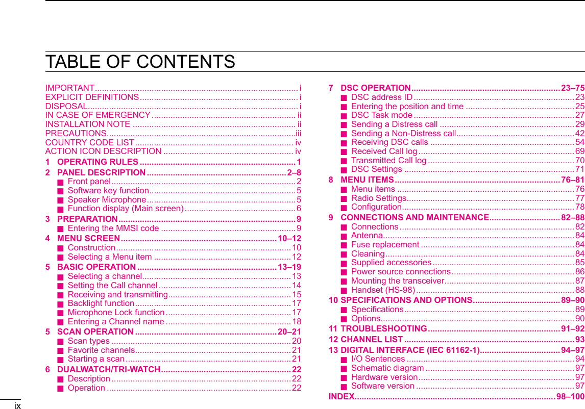
![62PANEL DESCRIPTIONNew2001 ■Speaker Microphoneq PTT SWITCH [PTT] (pp. ?, ?) Hold down to transmit, release to receive.w UP/DOWN KEYS [▲]/[▼] (p. ?) Push to select the Favorite channels, change scanning direction or manually resume a scan. L When the “FAV on MIC” item is set to “OFF,” you can select all channels. (p. ?)e TRANSMIT POWER KEY [H/L] zPush to set the power level to high or low. (p. ?) LSome channels are set to only low power. z While holding down this key, turn ON the transceiver to turn the Microphone Lock function ON or OFF. (p. ?)r CHANNEL 16/CALL CHANNEL KEY [16/C] (p. ?) zPush to select Channel 16. zHold down for 1 second to select the Call channel. • The “CALL” icon is displayed.q PTT SWITCH [PTT]w UP/DOWN KEYS [Y]/[Z]e TRANSMIT POWER KEY [H/L]Microphoner CHANNEL 16/ CALL CHANNEL KEY [16/C]Information areaSoftware Key area (p. ?)Channel areaMode/Task areaPosition andTime area ■Function display (Main screen)Status area DMode/Task areaThe current mode is displayed in the Mode and Task area.Indicator DescriptionDisplayed in the Standby mode.Displayed while in the Radio Telephone (RT) mode. (p. ?) L “ ” is displayed when the RT mode task is activated. L Returns to the Standby mode if no operation occurs during the preset period of time. (p. ?)Displayed after making or receiving a DSC call. (p. ?) L If the transceiver is in the Multi Task mode, the number of DSC tasks is displayed by the indicator.](https://usermanual.wiki/ICOM-orporated/388600/User-Guide-3263423-Page-16.png)
![9New200123PREPARATION 3145678910111213141516 ■Entering the MMSI codeFirst, you must enter the 9 digit MMSI (Maritime Mobile Service Identity: DSC self ID) code at power ON.NOTE: You can enter this initial code ONLY ONCE. After entry, only your dealer or distributor can change it. If you have already entered your MMSI code, these procedures are not necessary.1. Hold down [ ] for 1 second to turn ON the transceiver. • Three short beeps sound. • “Push [ENT] to Register Your MMSI” is displayed.2. Push [ENT] to enter the MMSI code entry mode.Push • Push [CLR] to cancel the entry. In that case, the transceiver displays “Push [ENT] to Register Your MMSI” again.3. Enter your 9 digit MMSI code.4. After entering the 9th digit, push [Finish] to set the ID.5. Reenter your MMSI code to confirm.6. After entering the 9th digit, push [Finish] to register the ID. • When you successfully enter your MMSI code, the following screen is displayed. • After that, the Main screen is displayed. The registered MMSI code is displayed at the top of the screen.+RotatePush+RotatePushPushPush](https://usermanual.wiki/ICOM-orporated/388600/User-Guide-3263423-Page-19.png)
![10New2001New2001MENU SCREEN4You can use the Menu screen to set infrequently changed values or function settings. ■ConstructionThe Menu screen is constructed in a tree structure.You can go to the next tree level with [ENT], or go back a level with [CLR]. LSee page iv for details.To select an item, rotate [CH/ENT].Rotate •Compose Distress (p. ??)Nature of Distress Select a Nature of Distress option.Position • Latitude Displays latitude data. • Longitude Displays longitude data. • UTC Displays UTC offset data. •Compose Non-Distress (p. ??)Message Type Select a Message Type option.AddressEnter a destination address.Position*1Enter your position. • Latitude*1Displays latitude data. • Longitude*1Displays longitude data. • UTC*1Displays UTC offset data.Category Select a Category option.Mode*1Select a Mode option.Channel*1Select an Intership channel. •AIS (p. ??)Displays the AIS plotter. •Hailer (p. ??)Displays the Hailer function screen. •Horn (p. ??)Manual Horn Hold down [Horn] to sound a horn.Auto Foghorn Select the automatic foghorn pattern.Frequency Select the foghorn’s audio frequency. •Intercom*2 (p. ??)RADIO Displays the transceiver’s name.SUB UNIT 1, 2, 3 Displays name of the unit that are connected for the Intercom function. •GPS/GNSS Information (p. ??)Displays the GPS or GNSS information. •AquaQuake (p. ??)Displays the AquaQuake function screen. •Conguration (p. ??)Key Beep Turn the Key Beep function ON or OFF.Key Assignment Select the items to the assignable keys.UTC Offset Set the UTC Offset.Inactivity Timer • Not DSC RelatedSet the inactivity timer for not DSC related calls. • DSC Related Set the inactivity timer for DSC related calls. • Distress Related Set the inactivity timer for Distress related calls. • RT Related Set the inactivity timer for the Radio Telephone mode.Speaker • Internal The internal speaker is ON and the external speaker is OFF. • External The internal speaker is OFF and the external speaker is ON.](https://usermanual.wiki/ICOM-orporated/388600/User-Guide-3263423-Page-20.png)
![124MENU SCREENNew2001 ■Selecting a Menu itemFollow the procedures described below to select a Menu item.Example: Set the Tri-watch function.1. Push [MENU] to display the MENU screen.2. Rotate [CH/ENT] to select “Radio Settings,” then push [ENT].+PushRotate3. Rotate [CH/ENT] to select “Dual/Tri-Watch,” then push [ENT].+PushRotate4. Rotate [CH/ENT] to select “Tri-Watch,” and then push [ENT].+PushRotate • Sets the Tri-watch function, and then goes back to the RADIO SETTINGS screen, after pushing [ENT].5. Push [MENU] to return to the Main screen.](https://usermanual.wiki/ICOM-orporated/388600/User-Guide-3263423-Page-22.png)
![135BASIC OPERATIONNew200112345678910111213141516New2001 DSelecting a regular channel zRotate [CH/ENT]. zPush [∫] or [√]. z Push the keypad to directly enter the desired channel number. (Example: Selecting Channel 22) Push [2 abc] → [2 abc]. ■Selecting a channel DSelecting Call channelYou have a leisure use Call channel for quick recall.To set your most used channel, see page ??.The default Call channel differs, depending on the transceiver version. z Hold down [16/C] for 1 second.Displayed DSelecting Channel 16Channel 16 is the distress and safety channel. It is used for establishing initial contact with a station, and for emergency communications. While standing by, you must monitor Channel 16. zPush [16/C].twicePush](https://usermanual.wiki/ICOM-orporated/388600/User-Guide-3263423-Page-23.png)
![145BASIC OPERATIONNew2001 ■Selecting a channel (Continued) DSelecting a channel groupChannel Groups are preset into your transceiver. You can select the Channel Group between USA, International, Canadian, DSC, and ATIS, depending on the transceiver version.Version Preset Channel GroupUSA INT CAN DSC ATISUSA UK European Dutch German Australian Chinese 1. Push [MENU]. • The “MENU” screen is displayed.2. Rotate [CH/ENT] to select “Radio Settings,” then push [ENT]. +PushRotate3. Rotate [CH/ENT] to select “Channel Group,” then push [ENT]. +PushRotate4. Rotate [CH/ENT] to select the Channel Group, then push [ENT]. +PushRotate5. Push [MENU] to return to the Main screen. • The selected Channel Group’s icon is displayed on the Main screen.](https://usermanual.wiki/ICOM-orporated/388600/User-Guide-3263423-Page-24.png)
![155BASIC OPERATIONNew200112345678910111213141516 DWeather channels and Weather Alert functionFor the USA and Australian versions, the transceiver has 10 preset Weather channels. You can use these channels to monitor broadcasts from the National Oceanographic and Atmospheric Administration (NOAA). The transceiver automatically detects a Weather alert tone on the selected weather channel, or while scanning.Selecting a Weather channel1. Push [Ω] or [≈] until “CH/WX” is displayed in the Software Key area.2. Push [CH/WX] . Push • “WX” is displayed instead of the Channel Group icon.3. Rotate [CH/ENT] to select a Weather channel. RotateSetting the Weather Alert function L See page ?? for details on the Weather Alert function.1. Push [MENU]. • The “MENU” screen is displayed.2. Rotate [CH/ENT] to select “Radio Settings,” then push [ENT].3. Rotate [CH/ENT] to select “WX Alert,” then push [ENT]. +PushRotate • The “WX ALERT” screen is displayed.4. Rotate [CH/ENT] to select “On with Scan” or “On,” then push [ENT].5. Push [MENU] to return to the Main screen. • “ ” is displayed next to “WX” on the Main screen.](https://usermanual.wiki/ICOM-orporated/388600/User-Guide-3263423-Page-25.png)
![165BASIC OPERATIONNew2001By default, a Call channel is set in each Channel Group.You can set the Call channel with your most often-used channel for quick recall.1. Push [MENU]. • The “MENU” screen is displayed.2. Rotate [CH/ENT] to select “Radio Settings,” then push [ENT].3. Rotate [CH/ENT] to select “Call Channel,” then push [ENT]. +PushRotate • The “CALL CHANNEL” screen is displayed.4. Rotate [CH/ENT] to select a channel to be set as the Call channel, then push [ENT].5. Push [MENU] to return to the Main screen. ■Setting the Call channelTIP: To conrm that your setting is correctly set, hold down [16/C] for 1 second. (p. ??) ■ Microphone Lock functionThe Microphone Lock function electrically locks [∫], [√], [16/C] and [H/L] on the supplied microphone. This prevents accidental channel changes or function access. While holding down [H/L] on the microphone, hold down [ ] for 1 second to turn ON the transceiver. • The Microphone Lock function is turned ON or OFF.[∫], [√][16/C][H/L]](https://usermanual.wiki/ICOM-orporated/388600/User-Guide-3263423-Page-26.png)
![175BASIC OPERATIONNew200112345678910111213141516 ■Receiving and transmitting1. Hold down [ ] for 1 second to turn ON the transceiver. L If no MMSI code is entered, “Push [ENT] to Register Your MMSI” is displayed. (p. ??)2. Rotate [VOL/SQL] to adjust the audio level.3. Push [VOL/SQL] once or twice to open the “SQL Setting” window, then rotate [VOL/SQL] to adjust the squelch level until the noise just disappears.4. Select a channel. (p. ??) InformationL • When receiving a signal, “ ” is displayed. • You can use Channel 70 only for Digital Selective Calling (DSC) transmissions. • When the “FAV on MIC” item is set to “OFF,” you can select all channels using the [∫] or [√] keys on the microphone. (p. ??)5. Push [Ω] or [≈] until “HI/LO” is displayed in the Software Key area.6. Push [HI/LO] to select an output power high or low. InformationL • “25W” is displayed when high power is selected. Choose high power for longer distance communications. • “1W” is displayed when low power is selected. Choose low power for short range communications. • Some channels are restricted to low power.7. Hold down [PTT], and speak at your normal voice level. • “ ” is displayed.8. Release [PTT] to return to receive.Microphone47, 8612, 36IMPORTANT: To maximize the readability of your transmitted signal at a receiver station, pause a second after pushing [PTT], and then hold the microphone 5 to 10 cm from your mouth and speak at your normal voice level.NOTE for the Time-out Timer (TOT) function:The TOT function inhibits continuous transmission beyond a preset time period after the transmission starts.10 seconds before transmission is cut off, a beep sounds to indicate the transmission will be cut off, and “TOT” is displayed in the channel name eld. You cannot transmit again for 10 seconds after it is cut off.CAUTION: DO NOT transmit without an antenna. It will damage the transceiver.45](https://usermanual.wiki/ICOM-orporated/388600/User-Guide-3263423-Page-27.png)
![185BASIC OPERATIONNew2001 ■Backlight functionThe function display and keys can be backlit for better visibility under low light conditions. And, you can set the Backlight mode to Day mode or Night mode.The Day mode is for the daytime operation, and the screen items are in color.The Night mode is for the nighttime operation, and the screen items are in black and red.1. Push [Ω] or [≈] until “Backlight” is displayed in the Software Key area.2. Push [Backlight] to open the “Backlight Settings” window. Push3. Push [∫] or [√] to select “Day Mode” or “Night Mode.” Push4. Rotate [CH/ENT] to adjust the backlight level, then push [ENT]. +PushRotate L The backlight level is adjustable in 7 levels and “OFF.”* * “OFF” is selectable only for the Day mode.TIP: In the “Backlight Setting” window, if you push no key for about 5 seconds, the transceiver automatically returns to the Normal operation mode.](https://usermanual.wiki/ICOM-orporated/388600/User-Guide-3263423-Page-28.png)
![195BASIC OPERATIONNew200112345678910111213141516You can rename each channel with a unique alphanumeric ID of up to 10 characters. This may be helpful to indicate the frequency's use.1. Cancel the Dualwatch, Tri-watch or Scan function, if activated.2. Select a channel. (p. ??)3. Push [Ω] or [≈] until “Channel Name” is displayed in the Software Key area.4. Push [Channel Name] . Push5. Enter a channel name. Push+Rotate ■Entering a Channel name InformationL • You can enter the following characters by pushing the keypad one or more times.KEY ENTRY KEY ENTRY[1] 1[6] 6 M N O[2] 2 A B C [7] 7 P Q R S[3] 3 D E F [8] 8 T U V[4] 4 G H I [9] 9 W X Y Z[5] 5 J K L [0] 0 . (period) • To move the cursor, rotate [CH/ENT]. • To enter a symbol, push [“!$?”] . And then push [Y], [Z], [Ω], or [≈] to select the desired character, then push [ENT]. • To correct an entry, move the cursor to the character, and then enter the correct character.6. After entering, push [Finish] to return to the Main screen.](https://usermanual.wiki/ICOM-orporated/388600/User-Guide-3263423-Page-29.png)
![205BASIC OPERATIONNew2001 ■Using the AquaQuake water draining functionWater in the speaker grill may mufe the sound coming from the speaker. The AquaQuake Water Draining function removes water from the speaker grill by vibrating the speaker.1. Push [MENU]. • The “MENU” screen is displayed.2. Rotate [CH/ENT] to select “AquaQuake,” then push [ENT].3. Hold down [Aqua Quake] until all water is removed from the speaker grill. Hold down • A low frequency vibration beep sounds to drain the water, regardless of the volume level setting. L This function is activated for a maximum of 10 seconds, even if you continue to hold down the Software Key.4. Push [MENU] to return to the Main screen.](https://usermanual.wiki/ICOM-orporated/388600/User-Guide-3263423-Page-30.png)
![206SCAN OPERATION (Except for the Dutch version)New200112345678910111213141516 ■Scan typesExcept for the Dutch version, you can nd ongoing calls by scanning the Favorite channels without rotating [CH/ENT].The IC-M605 and IC-M605 EURO have two scan types. • Priority scan • Normal scanBefore you start a scan: • Set the desired channels you want to scan as Favorite channels. (Scans only Favorite channels.) (p. 21) • Set the desired scan type to “Normal" or “Priority.” (p. 77)NORMAL SCANA Normal scan sequentially scans all Favorite channels. However, the scan does not check Channel 16 unless it is set as a Favorite channel.CH 01 CH 02CH 03CH 04CH 05CH 06PRIORITY SCANA Priority scan sequentially scans all Favorite channels while monitoring Channel 16.CH 16CH 01 CH 02CH 03CH 04CH 05CH 06When a signal is received:• On Channel 16The scan pauses until the signal on Channel 16 disappears.• On a channel other than Channel 16:The scan switches to Dualwatch, until the signal disappears.](https://usermanual.wiki/ICOM-orporated/388600/User-Guide-3263423-Page-31.png)
![216SCAN OPERATION (Except for the Dutch version)New2001New2001 ■Favorite channelsYou can quickly recall often-used channels by setting them as Favorite channels.All channels are set as Favorite channels by default. DSetting1. Rotate [CH/ENT] to select a channel.2. Push [Favorite] to set the channel as a Favorite channel. • “ ” is displayed. ■Starting a scan1. Push [Scan] to start a scan. • During a Priority scan, “SCAN 16” is displayed. • During a Normal scan, “SCAN” is displayed.2. Push [Scan] again to cancel the scan. • “SCAN 16” or “SCAN” disappears. DSelecting zPush [∫] or [√] on the microphone. • Non-Favorite channels are skipped and not displayed. • When the “FAV on MIC” item is set to “OFF,” you can select all channels. (p. 78) DClearing1. Select a Favorite channel to clear.2. Push [Favorite] to clear the channel as the Favorite channel. • “ ” disappears.Example: Starting a priority scan.Scanning startsWhen a signal is receivedNOTE: • When a signal is received, the scan pauses until the signal disappears, or resumes after pausing for 5 seconds, depending on the “Scan Timer” setting. (p. 77) • You can check the scanning channel, change the scan direction, or manually resume the scan by pushing [∫] or [√] on either the transceiver or the microphone. • A beep tone sounds and “16” blinks when a signal is received on Channel 16 during a Priority scan. • In order to properly receive signals, you must adjust the squelch to the proper level. (p. 15)PushTIP: You can clear all Favorite channels in the Menu screen. (p. 78)TIP: You can select all channels by rotating [CH/ENT] or pushing [∫] or [√] on the transceiver. (p. 13)](https://usermanual.wiki/ICOM-orporated/388600/User-Guide-3263423-Page-32.png)
![227DUALWATCH/TRI-WATCH (Except for the Dutch version)12345678910111213141516New2001 ■DescriptionDualwatch and Tri-watch are convenient for monitoring Channel 16 while you are listening on another channel.When a signal is received on the Channel 16.Dualwatch resumes after the signal disappears. When a signal is received:• On Channel 16Dualwatch or Tri-watch pauses on Channel 16 until the signal disappears.• On the Call channelTri-watch switches to Dualwatch until the signal on the Call channel disappears. ■Operation1. Select Dualwatch or Tri-watch in the Menu screen. (p. 77)2. Select a channel. (p. 13)3. Push [DW] to start Dualwatch or Tri-watch. • During Dualwatch, “DUAL 16” is displayed. • During Tri-watch, “TRI 16” is displayed. • A beep tone sounds and “16” starts to blink when a signal is received on Channel 16.4. Push [DW] again to cancel Dualwatch or Tri-watch.Example: Operating Dualwatch on Channel 07.PushDualwatch starts.Dualwatch Tri-watchCH 88CH 16Monitors Channel 16 while listening on another channel (example: CH 88).Monitors Channel 16 and the Call channel while listening on another channel (example: CH 88).CallchannelCH 88CH 16CH 9](https://usermanual.wiki/ICOM-orporated/388600/User-Guide-3263423-Page-33.png)
![New200123New2001DSC OPERATION8New2001 ■DSC address ID DEntering Individual ID1. Push [MENU].2. Select “Individual ID,” then push [ENT]. ( DSC Settings > Individual ID)3. Push [Add] . Push4. Enter a 9 digit Individual ID.TIP: You must set the rst digit for the Individual ID to between ʻ1ʼ and ʻ9.ʼ • The rst digit must be set to ‘0’ for a Group ID. • The rst two digits must be set to ‘0’ for any Coast station ID.5. After entering all 9 digits, push [Finish] .6. Enter the ID name. LSee page XX for text entry details.You can enter a total of 100 DSC address IDs (Individual ID: 75, Group ID: 25), and assign a name of up to 10 characters.7. After entering, push [ENT]. • The entered Individual ID and name are added to the ID list.8. Push [MENU] to return to the Main screen.+RotatePush+RotatePush](https://usermanual.wiki/ICOM-orporated/388600/User-Guide-3263423-Page-34.png)
![New2001248DSC OPERATIONNew200112345678910111213141516New2001New2001 DEntering Group ID1. Push [MENU].2. Select “Group ID,” then push [ENT]. (DSC Settings > Group ID)3. Push [Add] . Push4. Enter a 9 digit Group ID. 5. After entering all 9 digits, push [Finish] .6. Enter the ID name. LSee page 18 for text entry details.7. After entering, push [Finish] . • The entered Group ID and name are added to the ID list.8. Push [MENU] to return to the Main screen. DDeleting an entered ID1. Push [MENU].2. Select “Individual ID” or “Group ID,” then push [ENT]. ( DSC Settings > Individual ID) (DSC Settings > Group ID)3. Rotate [CH/ENT] to select the ID to delete.4. Push [Delete] . Push • The exit conrmation dialog is displayed.5. Push [OK] . • After deleting, returns to the ID list screen.6. Push [MENU] to return to the Main screen.TIP: You must set the rst digit for a Group ID to ‘0.’• The rst digit must be set to between ‘1’ and ‘9’ for an Individual ID.• The rst two digits must be set to ‘0’ for any Coast station ID.+RotatePush+RotatePush](https://usermanual.wiki/ICOM-orporated/388600/User-Guide-3263423-Page-35.png)
![258DSC OPERATIONNew2001 ■Entering the position and timeA Distress call should include the ship’s position and time. When a GPS receiver compatible with the NMEA 0183 format is connected, position and UTC time are automatically included.If no GPS data is received, you should manually enter your position (latitude and longitude) and Universal Time Coordinated (UTC) time.• Manual entry is disabled when a valid GPS data is received.• Manually entered position and time are valid for only 23.5 hours.1. Push [MENU].2. Select “Position Input,” then push [ENT]. (DSC Settings > Position Input)3. Enter your latitude position. To select ʻNʼ (North latitude) or ʻSʼ (South latitude), push any keypad key when the cursor is on the ‘N’ or ‘S’ position.4. After entering, push [Finish] .5. Enter your longitude position. L To select W (West longitude) or E (East longitude), push any keypad key when the cursor is on the ‘W’ or ‘E’ position.6. After entering, push [Finish] .PushEnterCursor movesSet ‘W’ (West) or ‘E’ (East)RotatePush(any key)PushEnterCursor movesSet ‘N’ (North) or ‘S’ (South)RotatePush(any key)](https://usermanual.wiki/ICOM-orporated/388600/User-Guide-3263423-Page-36.png)
![268DSC OPERATIONNew200112345678910111213141516NOTE:While entering:• To move the cursor: Rotate [CH/ENT].• To correct the entry: Move the cursor to the character, then enter the correct character.• To clear the entry: Push [Y], [Z], [Ω], or [≈] to select “No Data,” then push [ENT]. When the following screen is displayed, push [ENT].• To return to the Main screen: Push [Exit] .• To go back to the previous screen: Push [Back] .When position and time data are set, Latitude, Longitude and UTC time are displayed.• Latitude: 25°32.1234N• Longitude: 135°23.4321E• UTC time: 12:00When no position and time data are set, “No Position” and “No Time” are displayed.7. Enter your UTC time.8. After entering, push [Finish] . • The DSC SETTINGS screen is displayed.9. Push [MENU] to return to the Main screen.PushEnterCursor movesRotatePush(any key)](https://usermanual.wiki/ICOM-orporated/388600/User-Guide-3263423-Page-37.png)
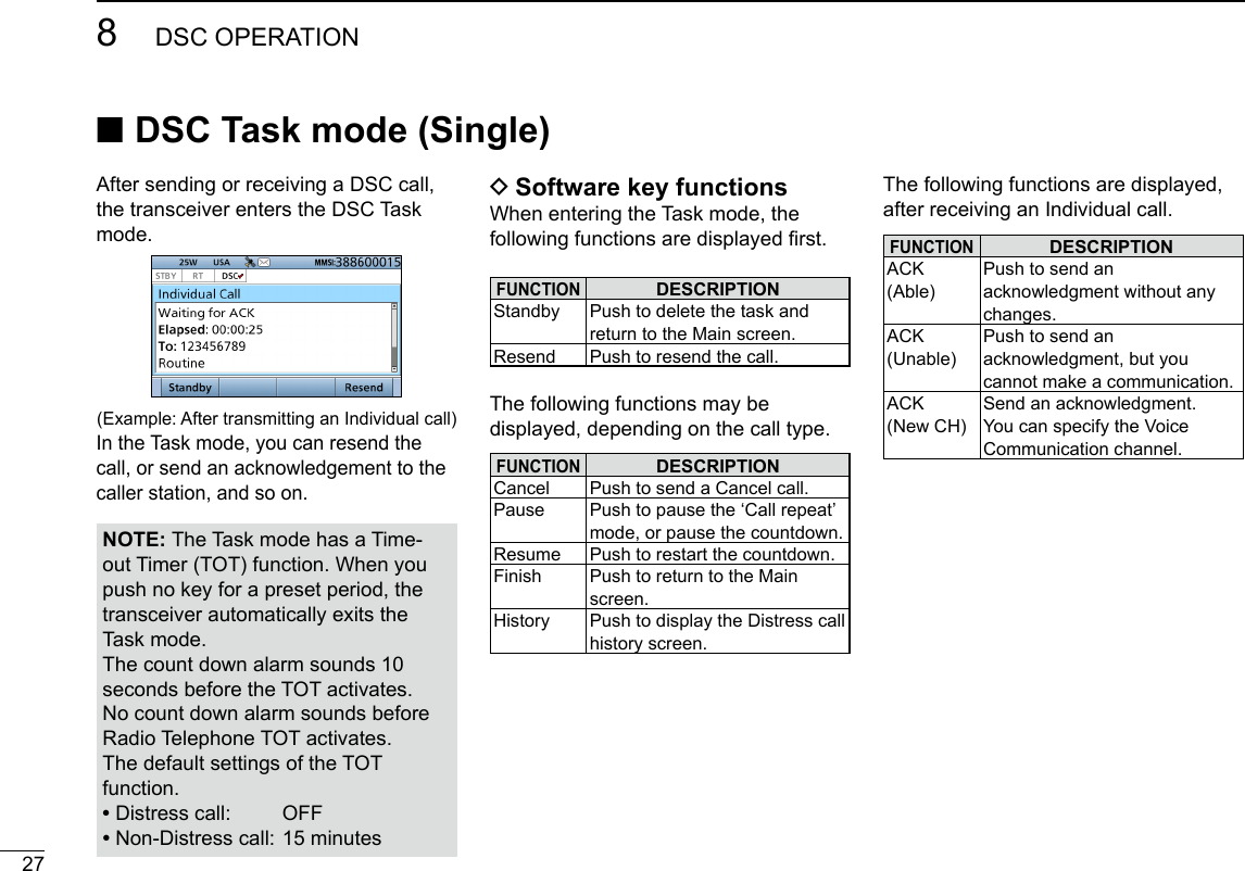
![288DSC OPERATIONNew200112345678910111213141516 ■DSC Task mode (Multiple)If the multiple task is enabled, the transceiver can hold up to 7 task in the Standby mode. The number of task is displayed in the Task area.(Example: After receiving a Group call)To use the Multiple task mode, select “Multiple” in the PROCEDURE menu (p. XX).NOTE: The Task mode has a Time-out Timer (TOT) function. When you push no key for a preset period, the transceiver automatically exits the Task mode.The count down alarm sounds 10 seconds before the TOT activates.No count down alarm sounds before Radio Telephone TOT activates.The default settings of the TOT function. • Distress call: OFF • Non-Distress call: 15 minutes DSoftware key functionsWhen entering the Task mode, the following functions are displayed rst.FUNCTIONDESCRIPTIONStandby Push to delete the task and return to the Main screen.Delete Push to delete the task and display the Task list.Hold Push to hold the task and display the Task list.Task List Push to hold the task and display the Task list.Resend Push to resend the call.The following functions may be displayed, depending on the call type.FUNCTIONDESCRIPTIONCancel Push to send a Cancel call.Pause Push to pause the ‘Call repeat’ mode, or pause the countdown.Resume Push to restart the countdown.Finish Push to return to the Main screen.History Push to display the Distress call history screen.The following functions are displayed, after receiving an Individual call.FUNCTIONDESCRIPTIONACK (Able)Push to send an acknowledgment without any changes.ACK (Unable)Push to send an acknowledgment, but you cannot make a communication.ACK (New CH)Send an acknowledgment. You can specify the Voice Communication channel. DTask ListWhen the number of task is displayed in the standby mode, you can enter the task mode by pushing [Task List] . L Push [Info] to display the detail of selected task.(For only USA version transceiver, depending on the presetting.)](https://usermanual.wiki/ICOM-orporated/388600/User-Guide-3263423-Page-39.png)
![298DSC OPERATIONNew2001 ■Sending a Distress callYou should send a Distress call if, in the opinion of the Master, the ship or a person is in distress and requires immediate assistance. L Emergency channel (Channel 70) is automatically selected to send a Distress call. DSimple call1. Confirm no Distress call is being received.2. Lift up the key cover, then hold down [DISTRESS] until “Transmitting” is displayed to send the Distress call. • While holding down [DISTRESS], count down beeps sound and both the key and display backlighting blink. •••3. After sending, the following screen is displayed. • Channel 16 is automatically selected.4. When receiving the acknowledgement: • Alarm sounds. • The following screen is displayed. 5. Push any [Alarm Off] .6. Push any [Close Call RCVD Window] .7. Hold down [PTT] to announce your situation.8. Push [Standby] to return to the Main screen.About 20 to 30 miles(Sea area A1)Distress AlertTransmissionShip in DistressOther shipCoastStationSee NOTE on page 31 for a Distress call.NEVER MAKE A DISTRESS CALL IF YOUR SHIP OR A PERSON IS NOT IN AN EMERGENCY.A DISTRESS CALL SHOULD BE MADE ONLY WHEN IMMEDIATE HELP IS NEEDED.TIP: If you want to compose a Distress call, see ʻRegular call.ʼ (p. 30)](https://usermanual.wiki/ICOM-orporated/388600/User-Guide-3263423-Page-40.png)
![308DSC OPERATIONNew200112345678910111213141516 DRegular callYou can compose the Distress call.Step 1. Display the COMPOSE DISTRESS screen1. Push [Compose Distress] . Push L To display the screen from the Menu screen: ([MENU] > Compose Distress)Step 2. Setting “Nature of Distress”1. Push [ENT].2. Select the option, then push [ENT]. (Example: Fire,Explosion) Options: Undesignated, Fire,Explosion, Flooding, Collision, Grounding, Capsizing, Sinking, Adrift, Abandoning Ship, Piracy, and Man Overboard. L The transceiver stores this setting for 30 seconds.You can skip Step 3 below if your position and time data are valid.In that case, go to Step 4.Step 3. Entering “Position”1. Select “Position,” then push [ENT]. • The position entry screen is displayed.2. Enter your position and time data. LSee page 25 for entering details.3. After entering, push [ENT].Step 4. Sending1. Lift up the key cover, then hold down [DISTRESS] until “Transmitting” is displayed to send the Distress call. • While holding down [DISTRESS], count down beeps sound and both the key and display backlighting blink. •••Push+PushRotate](https://usermanual.wiki/ICOM-orporated/388600/User-Guide-3263423-Page-41.png)
![318DSC OPERATIONNew20012. After sending, the following screen is displayed. • Channel 16 is automatically selected. L See page 28 for details of the Task mode’s software key functions.NOTE:Transmitting:• A distress alert default contains: - Nature of distress: Undesignated distress (Simple call) Selected in Step 2 (Regular call) - Position information: The latest GPS or manual input position is held for 23.5 hours, or until the power is turned OFF.Waiting for an acknowledgement:• The transceiver automatically sends a Distress call every 3.5 to 4.5 minutes, until receiving an acknowledgement (‘Call repeat’ mode), or sending a DSC Cancel call. (p. 33)• To manually send a Distress Repeat call: Push [Resend] .• To view the call contents: Rotate [CH/ENT].• To pause the ‘Call repeat’ mode: Push [Pause] . To resume it: Push [Resume Countdown] .Step 5. Replying1. When the acknowledgement is received: • Alarm sounds. • The following screen is displayed.2. Push any [Alarm Off] .3. Push any [Close Call RCVD Window] .4. Hold down [PTT] to announce your situation.5. Push [Standby] to return to the Main screen. DRegular call (Continued) ■Sending a Distress call](https://usermanual.wiki/ICOM-orporated/388600/User-Guide-3263423-Page-42.png)
![328DSC OPERATIONNew200112345678910111213141516 DResending a Distress callWhile waiting for an acknowledgement, you can resend the call. (Repeat call)1. When “Waiting for ACK” is displayed, push [Resend] .Push L See page 28 for details of the Task mode’s software key functions.3. When the acknowledgement is received: • Alarm sounds. • The following screen is displayed.4. Push any [Alarm Off] .5. Push any [Close Call RCVD Window] .6. Hold down [PTT] to announce your situation.7. Push [Standby] to return to the Main screen.2. Lift up the key cover, then hold down [DISTRESS] until “Retransmitting” is displayed to resend the call. • While holding down [DISTRESS], count down beeps sound and both the key and display backlighting blink.•••](https://usermanual.wiki/ICOM-orporated/388600/User-Guide-3263423-Page-43.png)
![338DSC OPERATIONNew2001 ■Sending a Distress call (Continued)While waiting for an acknowledgement, you can send a Distress Cancel call.1. When “Waiting for ACK” is displayed, push [Cancel] .Push L See page 28 for details of the Task mode’s Software key functions.2. Push [Continue] to send a Distress Cancel call.Push3. After sending, the following screen is displayed.4. Hold down [PTT] to announce your cancel statement. L Rotate [CH/ENT] to view the cancel statement of the Distress Cancel call.5. Select the action. [Finish]: Finishes the Distress Cancel procedures. [Resend]: Sends a Distress Cancel call again.6. Push [Standby] to return to the Main screen. Push DSending a Distress Cancel call](https://usermanual.wiki/ICOM-orporated/388600/User-Guide-3263423-Page-44.png)
![348DSC OPERATIONNew20011234567891011121314151634You can send the Distress Relay acknowledgment only when the Distress Relay call is received.1. When a Distress Relay call is received: • Alarm sounds. • The following screen is displayed.2. Push any [Alarm Off] .3. Push [Accept] . • Enters the DSC Task mode.4. Push [≈] to scroll the software key functions.5. Push [ACK] .Push • The call contents screen is displayed. L Rotate [CH/ENT] to view the call contents.6. Push [Call] to send the Distress Relay acknowledgement.Push7. Hold down [PTT] to communicate.8. Push [Standby] to return to the Main screen. D Sending a Distress Relay acknowledgementTIP: When you push [Pause] in step 3, the countdown will be paused. Push [Resume] to restart the countdown.](https://usermanual.wiki/ICOM-orporated/388600/User-Guide-3263423-Page-45.png)
![358DSC OPERATIONNew2001 ■Sending a Non-Distress callTo ensure correct operation of the DSC function, conrm you correctly set the Channel 70 squelch level. (p. XX)NOTE:• Emergency channel (Channel 70) is automatically selected for calling.• If Channel 70 is busy, the transceiver stands by until the channel becomes clear. D Sending an Individual callThe Individual call function enables you to transmit a DSC signal to only a specic coast station or ship. After transmission, wait for an acknowledgement from the receiving station.You can communicate by voice after receiving the acknowledgement ‘ACK (Able).’1. Push [Compose Other] to display the COMPOSE NON-DISTRESS screen.Push L To display the screen from the Menu screen: ([MENU] > Compose Non-Distress)2. Push [ENT].3. Select the individual address, or “Manual Input,” then push [ENT]. (Example: STATION1)When you select “Manual Input” in step 3, push the keypad to manually enter the Individual ID. (p. XX)Push+PushRotate](https://usermanual.wiki/ICOM-orporated/388600/User-Guide-3263423-Page-46.png)
![368DSC OPERATIONNew2001123456789101112131415164. Select “Category,” then push [ENT].5. Select the option, then push [ENT]. (Example: Routine)When you select a coast station in step 3, the voice channel is automatically specied by the coast station. Therefore, skip steps 6 and 7, and go to step 8.6. Select “Channel,” then push [ENT].7. Select the voice channel, then push [ENT].NOTE: After receiving the acknowledgement:• The voice channel specied in step 7 is selected.• A different voice channel is selected if the station you called cannot use the channel.8. Push [Call] to send the Individual call.Push9. After sending, the following screen is displayed. L See page 28 for details of the Task mode’s Software key functions.10. When the acknowledgement is received: • Alarm sounds. • The following screen is displayed. (Example: ACK (Able))11. Push any [Alarm Off] .12. Push any [Close Call RCVD Window] .When you receive “ACK (Unable)” in step 10, skip step 13, and go to step 14.13. Hold down [PTT] to communicate.14. Push [Standby] to return to the Main screen.+PushRotate+PushRotate](https://usermanual.wiki/ICOM-orporated/388600/User-Guide-3263423-Page-47.png)
![378DSC OPERATIONNew2001 ■Sending a Non-Distress call (Continued)When receiving an Individual call, you can send an acknowledgement (‘Able,’ ‘Unable,’ or ‘New CH’) by using the on-screen prompts.1. When an Individual call is received: • Alarm sounds. • The following screen is displayed.2. Push any [Alarm Off] .3. Push [Accept] .Push • Enters the DSC Task mode.4. Push [≈] to scroll the software key functions.5. Select your action. [ACK (Able)]: Sends an acknowledgment without any changes. [ACK (Unable)]: Sends an acknowledgment, but you cannot make a communication. [ACK (New CH)]: Sends an acknowledgment. You can specify the Voice Communication channel.6. Push [Call] to send the Individual acknowledgement.When you push [ACK (Unable)] in step 5, skip step 7, and go to step 8.7. Hold down [PTT] to communicate.8. Push [Standby] to return to the Main screen. D Sending an Individual acknowledgement](https://usermanual.wiki/ICOM-orporated/388600/User-Guide-3263423-Page-48.png)
![388DSC OPERATIONNew200112345678910111213141516 DSending an All Ships callAll ships, that have DSC transceiver, use Channel 70 as their ‘listening channel.’ When you want to announce a message to these ships within range, use the ‘All Ships Call’ function.1. Push [Compose Other] to display the COMPOSE NON-DISTRESS screen. L To display the screen from the Menu screen: ([MENU] > Compose Non-Distress)2. Select “Message Type,” then push [ENT].3. Select “All Ships,” then push [ENT].4. Select “Category,” then push [ENT].5. Select the option, then push [ENT]. (Example: Safety)6. Select “Channel,” then push [ENT].7. Select the voice channel, then push [ENT].8. Push [Call] to send the All ships call.Push9. After sending, the following screen is displayed. L See page 28 for details of the Task mode's software key functions.10. Hold down [PTT] to announce the message.11. Push [Standby] to return to the Main screen.+PushRotate+PushRotate+PushRotate](https://usermanual.wiki/ICOM-orporated/388600/User-Guide-3263423-Page-49.png)
![398DSC OPERATIONNew2001 ■Sending a Non-Distress call (Continued) D Sending a Group callThe Group call function allows you to transmit a DSC signal to only a specic group.1. Push [Compose Other] to display the COMPOSE NON-DISTRESS screen. L To display the screen from the Menu screen: ([MENU] > Compose Non-Distress)2. Select “Message Type,” then push [ENT].3. Select “Group,” then push [ENT].4. Select “Address,” then push [ENT].5. Select the Group address or “Manual Input,” then push [ENT]. (Example: GROUP1)When you select “Manual Input” in step 5, push the keypad to manually enter the Group ID. (p. 24)6. Select “Channel,” then push [ENT].7. Select the voice channel, then push [ENT].8. Push [Call] to send the Group call.Push9. After sending, the following screen is displayed. L See page 28 for details of the Task mode’s software key functions.10. Hold down [PTT] to announce the message.11. Push [Standby] to return to the Main screen.+PushRotate+PushRotate+PushRotate](https://usermanual.wiki/ICOM-orporated/388600/User-Guide-3263423-Page-50.png)
![408DSC OPERATIONNew2001123456789101112131415161. When a Position Request call is received: • Alarm sounds. • The following screen is displayed.2. Push any [Alarm Off] .3. Push [Accept] . • Enters the DSC Task mode.4. Push [≈] to scroll the software key functions. D Sending a Position Request acknowledgement5. Select your action. [ACK (Able)]: Sends an acknowledgment with position and time data. [ACK (Unable)]: Sends an acknowledgment with no position and time data. L The call contents screen is displayed. L Rotate [CH/ENT] to view the call contents. • Change your position data, if the displayed data is invalid. (p. 25)6. Push [Call] to send the acknowledgement. • When [ACK (Able)] is selected in step 5, your position and time data are transmitted.7. Push [Standby] to return to the Main screen.TIP: When “Position ACK” is set to Auto, the transceiver automatically sends the acknowledgement. (p. 71)When a Position Request call is received, you can send an acknowledgement.](https://usermanual.wiki/ICOM-orporated/388600/User-Guide-3263423-Page-51.png)
![418DSC OPERATIONNew2001 ■Sending a Non-Distress call (Continued) D Sending a Test callTesting on the exclusive DSC distress and safety calling channels should be avoided as much as possible by using other methods.Normally the Test call would require no further communications between the two stations involved.1. Push [Compose Other] to display the COMPOSE NON-DISTRESS screen. L To display the screen from the Menu screen: ([MENU] > Compose Non-Distress)2. Select “Message Type,” then push [ENT].3. Select “Test.”4. Select “Address,” then push [ENT].5. Select the Individual address, or “Manual Input.” (Example: STATION1)When you select “Manual Input” in step 5, push the keypad to manually enter the Individual ID. (p. 23)6. Push [Call] to send the Test call.Push7. After sending, the following screen is displayed. L See page 28 for details of the Task mode’s Software key functions.+PushRotate+PushRotate](https://usermanual.wiki/ICOM-orporated/388600/User-Guide-3263423-Page-52.png)
![428DSC OPERATIONNew2001123456789101112131415168. When the acknowledgement is received: • Alarm sounds. • The following screen is displayed. 9. Push any [Alarm Off] .10. Push [Accept] . • Enters the DSC Task mode.11. Rotate [CH/ENT] to view the received message log.12. Push [Standby] to return to the Main screen.1. When a Test call is received: • Alarm sounds.2. Push any [Alarm Off] .3. Push [Accept] . • Enters the DSC Task mode.4. Push [≈] to scroll the Software key functions. D Sending a Test call acknowledgementTIP: When “Test ACK” is set to “Auto,” the transceiver automatically sends the acknowledgement. (p. 71)When a Test call is received, you can send an acknowledgement.5. Push [ACK] . Push • The call contents screen is displayed. L Rotate [CH/ENT] to view the call contents.6. Push [Call] to send the acknowledgement.7. Push [Standby] to return to the Main screen.](https://usermanual.wiki/ICOM-orporated/388600/User-Guide-3263423-Page-53.png)
![548DSC OPERATIONNew20011. When a Distress call is received: • Alarm sounds. • The following screen is displayed and the backlight blinks. • “ ” blinks. 2. Push any [Alarm Off] .3. Select your action. [Ignore]: Ignores the Call and return to the Main screen. [Hold]*: Holds the RX call task, and return to the previous screen.* Displayed only when “Multiple” is selected in the PROCEDURE menu (p. XX). ■Receiving DSC callsIMPORTANT!Distress call reception should stop after one sequence because the coast station should send back an ‘acknowledgement’ to the ship.If the distress call continues, even after the coast station sends back an ‘acknowledgement,’ the ship in distress may not receive the acknowledgement. In such cases, you should send back an ‘acknowledgement’ instead of the coast station and contact the coast station. (p. 34) [Pause]: Pauses the countdown. • To restart the countdown, push [Resume] . [Accept]: Enters the DSC Task mode. To send the acknowledgement, push [Accept] .DSC Task mode • Automatically selects Channel 16, and then you should monitor it, because a coast station may require assistance. • Rotate [CH/ENT] to view the call contents. • See page 28 for details of the Task mode’s Software key functions.NOTE: After receiving a DSC call “ ” continuously blinks when the transceiver has DSC call. or an unread DSC message in the Received Call Log. (p. 65) D Receiving a Distress Call](https://usermanual.wiki/ICOM-orporated/388600/User-Guide-3263423-Page-54.png)
![558DSC OPERATIONNew200112345678910111213141516 D Receiving a Distress acknowledgement1. When a Distress acknowledgement sent to another ship is received: • Alarm sounds. • The following screen is displayed and the backlight blinks. • “ ” blinks. 2. Push any [Alarm Off] .3. Push any [Close Call RCVD Window] . • Enters the DSC Task mode.DSC Task mode • Automatically selects Channel 16, and then monitor it, because a coast station may require assistance. • Rotate [CH/ENT] to view the call contents. • See page 28 for details of the Task mode’s Software key functions.4. Push [Standby] to return to the Main screen.](https://usermanual.wiki/ICOM-orporated/388600/User-Guide-3263423-Page-55.png)
![568DSC OPERATIONNew2001 ■Receiving DSC calls (Continued)1. When a Distress Cancel call is received: • Alarm sounds. • The following screen is displayed and the backlight blinks. • “ ” blinks. 2. Push any [Alarm Off] .3. Select your desired action. [Hold]: Holds the RX call task, and return to the previous screen. [Pause]: Pauses the countdown. • To restart the countdown, push [Resume] . [Accept]: Enters the DSC Task mode.DSC Task mode • Automatically selects Channel 16, and then you should monitor it, because a coast station may require assistance. • Rotate [CH/ENT] to view the call contents. • See page 28 for details of the Task mode’s Software key functions.4. Push [Standby] to return to the Main screen. D Receiving a Distress Relay call1. When a Distress Relay call is received: • Alarm sounds. • The following screen is displayed and the backlight blinks. • “ ” blinks. 2. Push any [Alarm Off] .3. Select the action. [Hold]: Holds the RX call task, and return to the previous screen. [Pause]: Pauses the countdown. • To restart the countdown, push [Resume] . D Receiving a Distress Cancel call](https://usermanual.wiki/ICOM-orporated/388600/User-Guide-3263423-Page-56.png)
![578DSC OPERATIONNew200112345678910111213141516 [Accept]: Enters the DSC Task mode. To send the acknowledgement, push [Accept] .DSC Task mode • Automatically selects Channel 16, and then monitor it, because a coast station may require assistance. • Rotate [CH/ENT] to view the call contents. • See page 28 for details of the Task mode’s Software key functions.4. Push [Standby] to return to the Main screen.1. When a Distress Relay acknowledgement is received: • Alarm sounds. • “ ” blinks. • The following screen is displayed and the backlight blinks. 2. Push any [Alarm Off] .3. Push any [Close Call RCVD Window] . • Enters the DSC Task mode. D Receiving a Distress Relay acknowledgementDSC Task mode • Automatically selects Channel 16, and then you should monitor it, because a coast station may require assistance. • [PTT] is activated for voice communication via Channel 16. • Rotate [CH/ENT] to view the call contents. • See page 28 for details of the Task mode’s Software key functions.4. Push [Standby] to return to the Main screen.TIP: See page 41 for details of sending acknowledgement.](https://usermanual.wiki/ICOM-orporated/388600/User-Guide-3263423-Page-57.png)
![588DSC OPERATIONNew2001 ■Receiving DSC calls (Continued)1. When an Individual call is received: • Alarm sounds. • The following screen is displayed and the backlight blinks. • “ ” blinks. 2. Push any [Alarm Off] .3. Select your desired action. [Ignore]: Ignores the Call and return to the Main screen. [Hold]: Holds the RX call task, and return to the previous screen. [Able]: Sends an acknowledgment without any changes. [Accept]: Enters the DSC Task mode. To send the acknowledgement, push [Accept] .DSC Task mode • Rotate [CH/ENT] to view the call contents. • See page 28 for details of the Task mode’s Software key functions.NOTE: When the “Individual ACK” item is set to “Auto,” the transceiver automatically sends an acknowledgement. Both the TX and RX calls are stored in the Transmitted and Received Call Logs. (pp. 69, 70)When you select [Accept] in step 3, you can send an acknowledgement in the DSC Task mode. To send the acknowledgement, go to step 4.If you return to the Main screen without sending the acknowledgement, go to step 7.4. Push the desired key to select an acknowledgement option.5. Push [Call] to send the Individual acknowledgement.6. Depending on the option selected in step 5, hold down [PTT] to communicate.7. Push [Standby] to return to the Main screen. D Receiving an Individual callTIP: When you send the acknowledgement, select one of three options, depending on your situation. See page 44 for details of the Individual acknowledgement procedures.](https://usermanual.wiki/ICOM-orporated/388600/User-Guide-3263423-Page-58.png)
![598DSC OPERATIONNew200112345678910111213141516When receiving “ACK (Able)”:You can make voice communication on the channel that you specied when you sent the call.1. When an Individual acknowledgement “ACK (Able)” is received: • Alarm sounds. • The following screen is displayed and the backlight blinks. • “ ” blinks. 2. Push any [Alarm Off] . D Receiving an Individual acknowledgement3. Push any [Close Call RCVD Window] . • Enters the DSC Task mode.DSC Task mode • Automatically selects the channel that you specied when you sent the call for voice communication. • Rotate [CH/ENT] to view the call contents. • See page 28 for details of the Task mode’s Software key functions.4. Hold down [PTT] to communicate.5. Push [Standby] to return to the Main screen.](https://usermanual.wiki/ICOM-orporated/388600/User-Guide-3263423-Page-59.png)
![608DSC OPERATIONNew2001 ■Receiving DSC calls D Receiving an Individual acknowledgement (Continued)3. Push any [Close Call RCVD Window] . • Enters the DSC Task mode.DSC Task mode • Rotate [CH/ENT] to view the call contents. • See page 28 for details of the Task mode’s Software key functions.4. Push [Standby] to return to the Main screen.When receiving “ACK (New CH)”:You can make voice communication on the channel that is proposed by the called station.1. When an Individual acknowledgement “ACK (New CH)” is received: • Alarm sounds. • The following screen is displayed and the backlight blinks. • “ ” blinks. 2. Push any [Alarm Off] .When receiving “ACK (Unable)”:You cannot make the voice communication.1. When an Individual acknowledgement “ACK (Unable)” is received: • Alarm sounds. • The following screen is displayed and the backlight blinks. • “ ” blinks. 2. Push any [Alarm Off] .](https://usermanual.wiki/ICOM-orporated/388600/User-Guide-3263423-Page-60.png)
![618DSC OPERATIONNew2001123456789101112131415163. Push any [Close Call RCVD Window] . • Enter the DSC Task modeDSC Task mode • Automatically selects the channel that is proposed by the called station for voice communication. • Rotate [CH/ENT] to view the call contents. • See page 28 for details of the Task mode’s Software key functions.4. Hold down [PTT] to communicate.5. Push [Standby] to return to the Main screen. D Receiving an All Ships call1. When an All Ships call is received: • Alarm sounds. • The following screen is displayed and the backlight blinks. • “ ” blinks. 2. Push any [Alarm Off] .3. Select your desired action. [Ignore]: Ignores the Call and return to the Main screen. [Hold]: Push [Hold] to return to the Main screen. [Pause]: Push [Pause] to pause the countdown. • To restart the countdown, push [Resume] . [Accept]: Push [Accept] to enter the DSC Task mode.DSC Task mode • Monitor the channel specied by the calling station for an announcement from the calling station. (Example: Channel 16) • Rotate [CH/ENT] to view the call contents. • See page 28 for details of the Task mode’s Software key functions.4. Push [Standby] to return to the Main screen.](https://usermanual.wiki/ICOM-orporated/388600/User-Guide-3263423-Page-61.png)
![628DSC OPERATIONNew2001 D Receiving a Group call1. When a Group call is received: • Alarm sounds. • The following screen is displayed and the backlight blinks. • “ ” blinks. 2. Push any [Alarm Off] .3. Select your desired action. [Ignore]: Ignores the Call and return to the Main screen. [Hold]: Holds the RX call task, and return to the previous screen.1. When a Position Request call is received: • Alarm sounds. • The following screen is displayed and the backlight blinks. 2. Push any [Alarm Off] .3. Select your desired action. ■Receiving DSC calls (Continued) [Pause]: Pauses the countdown. • To restart the countdown, push [Resume] . [Accept]: Enters the DSC Task mode.DSC Task mode • Monitor the channel specied by the calling station for an announcement from the calling station. (Example: Channel 08) • Rotate [CH/ENT] to view the call contents. • See page 28 for details of the Task mode’s Software key functions.4. Push [Standby] to return to the Main screen. D Receiving a Position Request CallNOTE: When “Position ACK” is set to “Auto,” the transceiver automatically replies to the call. Both the TX and RX calls are stored in the Transmitted and Received Call Logs. (Default: Manual)](https://usermanual.wiki/ICOM-orporated/388600/User-Guide-3263423-Page-62.png)
![638DSC OPERATIONNew200112345678910111213141516 [Ignore]: Ignores the Call and return to the Main screen. [Hold]: Holds the RX call task, and return to the previous screen. [ACK (Unable)]: Sends an acknowledgment with no position and time data. [ACK (Able)]: Sends an acknowledgment with position and time data. [Accept]: Enters the DSC Task mode.DSC Task mode • Rotate [CH/ENT] to view the call contents. • See page 28 for details of the Task mode’s Software key functions.4. Push [Standby] to return to the Main screen.TIP: See page 48 for details of sending an acknowledgement.1. When a Test call is received: • Alarm sounds. • The following screen is displayed and the backlight blinks. • “ ” blinks. 2. Push any [Alarm Off] .3. Select your desired action. [Ignore]: Ignores the Call and return to the Main screen. [Hold]: Holds the RX call task, and return to the previous screen. [ACK ]: Sends an acknowledgment. [Accept]: Enters the DSC Task mode.DSC Task mode • Rotate [CH/ENT] to view the call contents. • See page 28 for details of the Task mode’s Software key functions.4. Push [Standby] to return to the Main screen.NOTE: When “Test ACK” is set to “Auto,” the transceiver automatically replies to the call. Both the TX and RX calls are stored in the Transmitted and Received Call Logs. (Default: Auto) D Receiving a Test callTIP: See page 51 for details of sending an acknowledgement.](https://usermanual.wiki/ICOM-orporated/388600/User-Guide-3263423-Page-63.png)
![648DSC OPERATIONNew2001 ■Receiving DSC calls (Continued) D Receiving a Test acknowledgement1. When a Test acknowledgement is received: • Alarm sounds. • The following screen is displayed and the backlight blinks. • “ ” blinks. 2. Push any [Alarm Off] .3. Push any [Close Call RCVD Window] . • Enters the DSC Task mode.DSC Task mode • Rotate [CH/ENT] to view the call contents. • See page 28 for details of the Task mode’s Software key functions.4. Push [Standby] to return to the Main screen.](https://usermanual.wiki/ICOM-orporated/388600/User-Guide-3263423-Page-64.png)
![658DSC OPERATIONNew200112345678910111213141516 DDistress message1. Push [DSC Log] to display the RECEIVED CALL LOG screen. • To display the screen from the Menu screen: ( [MENU] > DSC Log > Received Call Log)2. Select “Distress,” then push [ENT].3. Select the message, then push [ENT]. +PushRotate4. Rotate [CH/ENT] to view the contents. • To view another message, push [CLR] to return to the previous screen. And then, select the message.5. Push [Exit] to return to the Main screen. ■Received Call log DOther messages1. Push [DSC Log] to display the RCVD CALL LOG screen. • To display the screen from the Menu screen: ( [MENU] > DSC Log > Received Call Log)2. Select “Others,” then push [ENT].3. Select the message, then push [ENT]. +PushRotate4. Rotate [CH/ENT] to view the contents. • To view another message, push [CLR] to return to the previous screen. And then, select the desired message.5. Push [Exit] to return to the Main screen.The transceiver automatically stores up to 50 distress messages and 50 other messages, and they can be used as a supplement to your logbook.• When there is an unread DSC message, “ ” blinks on the information area of the LCD.• “ ” is displayed when there are unread DSC messages.• “ ” is displayed when there are no unread DSC messages.• No icon is displayed when there are no DSC messages.• Distress messages are stored in “Distress.”Software key functions in the RECEIVED CALL LOG screen:[Exit]: Push to return to the Main screen.[Back]: Push to return to the previous screen.[Delete]: Push to delete the selected message.[Enter]: Push to go to the next screen.](https://usermanual.wiki/ICOM-orporated/388600/User-Guide-3263423-Page-65.png)
![668DSC OPERATIONNew2001 ■Transmitted Call logThe transceiver automatically stores up to 50 transmitted calls, and the logs can be used as a supplement to your logbook.1. Push [MENU].2. Select “Transmitted Call Log.” ( DSC Log > Transmitted Call Log) +PushRotate3. Select the desired message, then push [ENT]. +PushRotate4. Rotate [CH/ENT] to view the contents. • To view another message, push [CLR] to return to the previous screen. And then, select the desired message.5. Push [Exit] to return to the Main screen.Software key functions in the TRANSMITTED CALL LOG screen:[Exit]: Push to return to the Main screen.[Back]: Push to return to the previous screen.[Delete]: Push to delete the selected message.[Enter]: Push to go to the next screen.](https://usermanual.wiki/ICOM-orporated/388600/User-Guide-3263423-Page-66.png)
![678DSC OPERATIONNew200112345678910111213141516 D Automatic AcknowledgementYou can set the Automatic Acknowledgment function to acknowledge DSC calls.When you receive an Individual call, Position Request call, Polling Request call or Test call, the transceiver automatically sends each acknowledgement, if “Auto” is set. ■DSC Settings DPosition Input (See page XX) DIndividual ID (See page XX) DGroup ID (See page XX)When you set the “Individual ACK” item to “Auto (Unable),” and receive the Individual call, the transceiver automatically sends the acknowledgment, including “ACK (Unable)” (No Reason Given).1. Push [MENU].2. Select “Auto ACK.” ( DSC Settings > Auto ACK)3. Select the item. ( DSC Settings > Auto ACK > Individual ACK) ( DSC Settings > Auto ACK > Position ACK) ( DSC Settings > Auto ACK > Polling ACK) ( DSC Settings > Auto ACK > Test ACK)4. Select the option, then push [ENT]. Individual ACK +PushRotate (Default: Auto (Able)) Position ACK +PushRotate (Default: Manual) Polling ACK +PushRotate (Default: Manual) Test ACK +PushRotate (Default: Auto)5. Push [MENU] to return to the Main screen.](https://usermanual.wiki/ICOM-orporated/388600/User-Guide-3263423-Page-67.png)
![688DSC OPERATIONNew2001 DChannel Auto SwitchBy regulation, after receiving a DSC call, the transceiver changes the operating channel to the channel assigned by the received DSC call. However, when this setting is set to “OFF,” the function enables the transceiver to remain on the operating channel, even after receiving a Distress call.1. Push [MENU].2. Select “CH Auto Switch:,” then push [ENT]. ( DSC Settings > CH Auto Switch:)+PushRotate3. Select the option, then push [ENT]. ■DSC Settings (Continued)Accept after 10 sec.After receiving a DSC call, the transceiver remains on the current operating channel for 10 seconds. After that, the transceiver automatically switches to the channel that assigned by the received DSC call.Ignore after 10 sec.*1After receiving a DSC call, the transceiver remains on the current operating channel for 10 seconds. After that, the transceiver automatically switches to the channel that assigned by the received DSC call.Hold after 10 sec.*2After receiving a DSC call, the transceiver remains on the current operating channel for 10 seconds. After that, the transceiver automatically holds the received DSC call.ManualThe user need to select whether or not to accept the received DSC call.*1 Displayed only when DSC procedure is set to “Sigle” in the Procedure menu (p. XX)*2 Displayed only when DSC procedure is set to “Multiple” in the Procedure menu (p. XX)4. Push [Exit] to return to the Main screen. DDSC data outputWhen receiving a DSC call, this function makes the transceiver send the DSC data from its NMEA Output port to an external device.All Stations: Outputs the call from any vessel from the NMEA Output port.Station List: Outputs the call from any vessels listed on the Individual ID screen.OFF: Does not output any call to an external device (Default).](https://usermanual.wiki/ICOM-orporated/388600/User-Guide-3263423-Page-68.png)
![698DSC OPERATIONNew200112345678910111213141516 D Setting the Alarm Status• Safety• RoutineSelect whether or not to sound an alarm when receiving the Safety or Routine DSC call.1. Push [MENU].2. Select the item, then push [ENT]. ( DSC Settings > Alarm Status > Safety) ( DSC Settings > Alarm Status > Routine) (Example: Safety)+PushRotate3. Select the option, then push [ENT]. • On: Alarm sounds. (Default) • Off: Alarm does not sound.4. Push [MENU] to return to the Main screen.• WarningSelect whether or not to sound an alarm:• When no MMSI code is entered.• When the position data has not been updated for 10 minutes.• When the position data has not been manually updated for 4 hours.• After the invalid GPS position data or manually entered position data has not been updated for 23.5 hours.1. Push [MENU].2. Select “Warning,” then push [ENT]. ( DSC Settings > Alarm Status > Warning)+PushRotate3. Select the desired option, then push [ENT]. • On: Alarm sounds. (Default) • Off: Alarm does not sound.4. Push [MENU] to return to the Main screen.• Self-TerminateSelect whether or not to sound an alarm when receiving the same Distress call.1. Push [MENU].2. Select “Self-Terminate,” then push [ENT]. ( DSC Settings > Alarm Status > Self-Terminate)+PushRotate3. Select the desired option, then push [ENT]. • On: Alarm sounds. (Default) • Off: Alarm does not sound.4. Push [MENU] to return to the Main screen.](https://usermanual.wiki/ICOM-orporated/388600/User-Guide-3263423-Page-69.png)
![708DSC OPERATIONNew2001 ■DSC Settings (Continued)• DiscreteSelect whether or not to sound an alarm when receiving a lower priority DSC call while receiving a higher priority call.1. Push [MENU].2. Select “Discrete,” then push [ENT]. ( DSC Settings > Alarm Status > Discrete)+PushRotate3. Select the desired option, then push [ENT]. • On: Alarm sounds. (Default) • Off: Alarm does not sound.4. Push [MENU] to return to the Main screen. D Setting the Channel 70 Squelch levelSet the squelch level on Channel 70.The transceiver has 11 squelch levels between 1 (loose squelch), 10 (tight squelch) and ʻOpenʼ (squelch is completely open).1. Push [MENU].2. Select “CH 70 SQL Level,” then push [ENT].3. ( DSC Settings > CH 70 SQL Level:)+PushRotate4. Adjust the squelch level until the noise just disappears.+PushRotate5. Push [MENU] to return to the Main screen. DSelf Check TestThe Self Check test function sends transmit DSC signals to the receive AF circuit to compare and check the TX and RX signals at the AF level.1. Push [MENU].2. Select “Self Check test,” then push [ENT]. ( DSC Settings > Self Check Test)+PushRotate3. Push [ENT] to start the DSC loop test.Push • When the transmit DSC and receive DSC signals are matched, “OK” is displayed.4. Push [MENU] to return to the Main screen.](https://usermanual.wiki/ICOM-orporated/388600/User-Guide-3263423-Page-70.png)
![718DSC OPERATIONNew200112345678910111213141516 D Selecting the DSC procedure (For only the USA version transceivers)Select weather or not to enable the transceiver handling more than 2 tasks at same time.See page XX and page XX for the single task and multi task details.1. Push [MENU].2. Select “Self Check test,” then push [ENT]. ( DSC Settings > Procedure:) 3. Select the option, then push [ENT]. • Single: The transceiver handle the single task. • Multiple: The transceiver can handle up to 7 tasks at same time (Default).4. Push [MENU] to return to the Main screen.](https://usermanual.wiki/ICOM-orporated/388600/User-Guide-3263423-Page-71.png)
![728DSC OPERATIONNew2001When the optional MA-500TR class b ais transponder is connected to your transceiver, you can transmit an Individual DSC call to a selected AIS target, without entering the target’s MMSI code. In this case, the call type is automatically set to Routine.See page XX for connecting instructions.NOTE: To ensure correct operation of the DSC function, make sure you correctly set the CH70 SQL Level. (p. XX)Step 1: Operating the Transponder1. Select an AIS target on the plotter, target list or danger list display. • You can also go to the next step whenever the detail screen of the AIS target is displayed. • Conrm the transceiver is in the normal operating mode. Otherwise, you cannot make an Individual DSC call using the transponder.2. Push [DSC] to display the Voice channel selection screen, and then push [Y]/[Z] to select a desired Voice channel.* • Voice channels are already preset into the transponder in recommended order. * When a coast station is selected in step 1, a Voice channel will be specied by the coast station, therefore you cannot change the channel. The transponder will display “Voice Channel is specied by the Base station,” in this case.3. Push [DSC] to transmit an Individual DSC call to the AIS target. • If Channel 70 is busy, the transceiver stands by until the channel becomes clear. • If the transceiver cannot make the call, the transponder will display “DSC Transmission FAILED.” ■Making an Individual call using an AIS transponder](https://usermanual.wiki/ICOM-orporated/388600/User-Guide-3263423-Page-72.png)
![738DSC OPERATIONNew2001123456789101112131415164. After making the Individual DSC call, the transponder will display “DSC Transmission COMPLETED.” • Push [CLEAR] to return to the screen displayed before you entered the Voice channel selection screen in step 2. • The transceiver stands by on Channel 70 until an acknowledgement is received.Step 1: Operating the Transceiver5. When the acknowledgement is received, alarm sounds. z If the acknowledgement ‘Able to comply’ is received, push [ALARM OFF] to stop the alarm, and then select the Intership channel specied in step 2. • A different Intership channel will be selected if the station you called cannot use the channel. • To reply, push [PTT] and speak at a normal voice level. • You can check the MMSI code or the name, if entered, of the AIS target on the display. z If the acknowledgement ‘Unable to comply’ is received, push [ALARM OFF] to stop the alarm, then “INDIVIDUAL CALL FAILED” is displayed.6. After the communication is finished, push [Standby] to return to the normal operating mode.[Y][Z][CLEAR][DSC]TRANSPONDER](https://usermanual.wiki/ICOM-orporated/388600/User-Guide-3263423-Page-73.png)
![New200174New2001OTHER FUNCTIONS9 ■Using IntercomThe optional Intercom function enables you to talk between the deck and the cabin. The optional HM-229 commandmicV™ is required for Intercom operation.Connect the HM-229 as described on page 107. • Transmitting is disabled while using the intercom. • The received signal is muted while using the intercom.1. Push [MENU].2. Select “Intercom,” then push [ENT].3. Select the unit, then push [ENT]. • Enters the Intercom mode.4. Hold down [Call] to sound the intercom beeps. • The transceiver and the command microphone sound beeps while holding down [Call]. • “Call” is displayed.5. After releasing [Call], hold down [PTT] and speak into the microphone at a normal voice level. • “ Talk” is displayed. L To adjust the transceiver’s intercom volume level, rotate [VOL/SQL]. L To adjust the HM-229’s intercom volume level, rotate [VOL/SQL] (Dial) on the HM-229.6. After releasing [PTT], you can hear the response through the speaker.7. Push [EXIT] to return to the Main screen.NOTE: While in the Intercom mode, the transmit and receive functions are disabled. When the transceiver is transmitting, the Intercom function is disabled.+PushRotate](https://usermanual.wiki/ICOM-orporated/388600/User-Guide-3263423-Page-74.png)
![New2001759OTHER FUNCTIONSNew200112345678910111213141516 ■Using the RX HailerThe RX Hailer function enables you to hear the received audio on the deck or bridge through a Hailer speaker.Connect an external hailer speaker as described on page XX.1. Push [Ω] or [≈] until [RX Hailer] is displayed in the Software Key area.2. Push [RX Hailer] to enter the RX Hailer mode. • The “ ”icon is displayed. L Push [VOL/SQL] to open the volume adjustment screen. 3. To exit the RX hailer mode, push [RX Hailer] . • The “ ”icon disappears. ■Using the HailerYou can talk without leaving the bridge by using the 2 way hailer function.Connect an external hailer speaker as described on page XX.• You cannot transmit while using the hailer.1. Push [MENU].2. Select “Hailer,” then push [ENT]. • Hailer screen is displayed.3. Hold down [PTT] and speak at your normal voice level.4. While holding down [PTT], the screen shown to the right is displayed. L Push [VOL/SQL] to open the volume adjustment screen.NOTE: While in the hailer mode, the transmit and receive functions are disabled. When the transceiver is transmitting, the hailer function is disabled.](https://usermanual.wiki/ICOM-orporated/388600/User-Guide-3263423-Page-75.png)
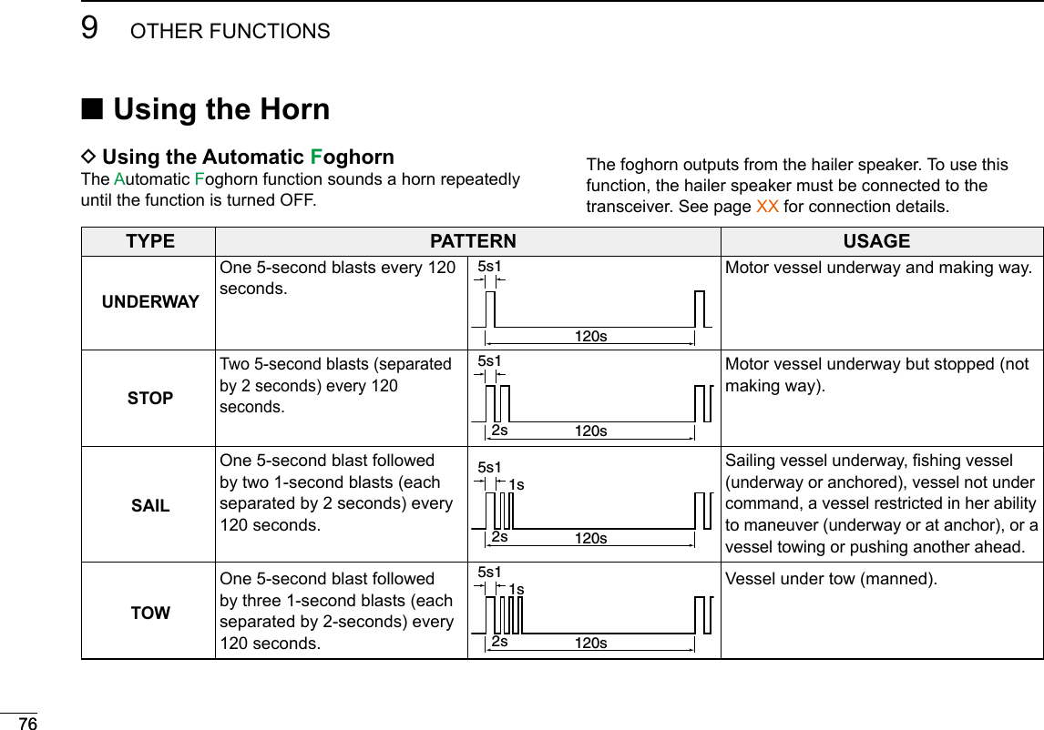
![779OTHER FUNCTIONSNew2001123456789101112131415161. Push [MENU].2. Select “Auto Foghorn:,” and then push [ENT]. (Horn > Auto Foghorn:)3. Select the foghorn pattern, then push [ENT].4. Rotate [CH/ENT] to adjust the foghorn level. 5. Push [Exit] to return to the Main screen. • The “ ”icon is displayed. L To turn OFF the Auto Foghorn, select “Off” in the “Auto Foghorn:” menu. DManual Horn function1. Push [MENU].2. Select “Manual Horn” then push [ENT]. (Horn > Manual Horn:)3. Hold down [Horn] to sound a horn. • While holding down [Horn], the horn sounds, and the screen shown to the right is displayed. • To adjust the horn volume level, rotate dial.4. Push [EXIT] to return to the Main screen.NOTE: While in the Horn mode, the transmit and receive functions are disabled. When the transceiver is transmitting, the Horn function is disabled.](https://usermanual.wiki/ICOM-orporated/388600/User-Guide-3263423-Page-77.png)
![■Using the voice recorderThe transceiver has an automatic recording function that can record the last 120 seconds of the receiving audio. You can playback the audio that you could not hear clearly. z Starts recording automatically when the signal is received.• The “ ” icon is displayed while recording.• Stops recording 3 seconds after the signal disappears.• Stops recording when the channel is changed.• The recorded voice data is erased when the transceiver is turned OFF. DPlayback the recorded voice z Push [RX Play] to playback the recorded voice. • The “ ” icon is displayed while playing. z Push [Stop] to stop playing back the recorded voice.78New2001789OTHER FUNCTIONS ■ Using the Voice Scrambler The Voice Scrambler provides private communications. In order to receive or send scrambled transmissions, you must activate the scrambler function. You also need to set the scrambler code in the Menu screen. (p. 102)The scrambler function automatically turns OFF when Channel 16 or 70 is selected.1. Select an operating channel except Channel 16, 70 or weather channels.2. Push [Ω] or [≈] until [SCBL] is displayed in the Software Key area.3. Push [SCBL] to turn the Voice Scrambler ON or OFF. • The “SBL” icon is displayed when the voice scrambler is ON. DSetting scrambler codesSet the code between 1 and 32 in the Menu screen. In order to understand each other, all transceivers in your group must have the same scramble code. See page XX for scrambler code setting details.](https://usermanual.wiki/ICOM-orporated/388600/User-Guide-3263423-Page-78.png)
![818110AIS RECEIVER ■Function displayThere are 3 types of function display; plotter, target list and danger list. Select the display type using the [Display] key. zPush [AIS] to display the Plotter screen. DPlotter screenIf the GPS is connected and it receives signals from a satellite, the plotter screen shows the display range and the icons of the AIS targets.qtre wq INFORMATION Display the selected target’s information. w TARGET BOX Shows the selected AIS target. L When a target box is displayed, push [ENT] to display the detail screen of the selected AIS target.e YOUR VESSEL ICON Displayed in the center of the screen. L When “N-UP” is displayed, the vessel icon automatically points in the direction you are heading, in 45 degrees steps. L When “COG-UP” is displayed, the vessel icon constantly points to the top of the plotter screen. L When your vessel moves less than 2 knots, the “ ” icon is displayed.r DISPLAY RANGE Shows the selected display range. Push [Range] to select display range. L 0.125, 0.25, 0.5, 0.75, 1.5, 3, 6, 12, 24 nm (nautical miles) are selectable.t DISPLAY TYPE Shows the selected display type. You can select the display type from “AIS SET” in the menu screen (p. 88) L When “N-UP” is displayed, the top of the plotter screen represents North. L When “COG-UP” is displayed, the top of the plotter screen represents the direction your course is heading.12346781011121314151649](https://usermanual.wiki/ICOM-orporated/388600/User-Guide-3263423-Page-81.png)
![8210 AIS RECEIVERNew2001Function display (Continued)• Description of the iconsIcon DescriptionAIS target: VesselThe tip of the target triangle automatically points in the direction it’s heading.The icon blinks when the AIS target is closer than your CPA and TCPA settings. (Dangerous target)AIS target: Lost target*The target triangle is marked with a diagonal line.AIS target: Base StationAIS target: Search and Rescue (SAR)AIS target: Aids to Navigation (AtoN)AIS target: AIS-SART, MOB and EPIRB-AIS* A vessel is regarded as a “Lost target” after a specied period of time has passed since the vessel last transmitted data. The “Lost target” icon disappears from the plotter screen 6 minutes and 40 seconds after the vessel was regarded as a “Lost target.” Ask your dealer for details. DTarget list screenIn the plotter screen, push [DISP] to switch to the target list screen, which shows all AIS targets being detected by the transponder.The AIS target data is sorted by the distance from your vessel, and the closest target is located on the top of the list.• Rotate [CH/ENT] to select an AIS target.• Push [INFO] to display the detail screen of the selected AIS target. (p. XX)• Push [DSC] to transmit DSC call to selected AIS target. qwq THE NUMBER OF TARGETS Shows the number of AIS targets which are being detected by the transceiver.w TARGET INFORMATION Shows the following AIS target information:• MMSI code or name.• Range (RNG) from your vessel to the target (unit: nautical mile).• Bearing (BRG) from your vessel to the target (unit: degree).](https://usermanual.wiki/ICOM-orporated/388600/User-Guide-3263423-Page-82.png)
![8310AIS RECEIVERNew200112345678910111213141516 DDanger list screenIn the target list display, push [DISP] to switch to the danger list screen, which helps you to nd any dangerous target whose CPA is within 6 nm (nautical miles) and TCPA is within 60 minutes of your vessel.• Rotate [CH/ENT] to select an AIS target.• Push [INFO] to display the detail screen of the selected AIS target. (p. XX)• Push [DSC] to transmit DSC call to selected AIS target. qwq THE NUMBER OF DANGEROUS TARGETS Shows the number of AIS targets which are being detected by the transceiver.w DANGER TARGET INFORMATION Shows the following dangerous target information: • MMSI code or name. • CPA: Closest Point of Approach (unit: nautical mile). • TCPA: Time to CPA (unit: minute).](https://usermanual.wiki/ICOM-orporated/388600/User-Guide-3263423-Page-83.png)
![8410 AIS RECEIVERNew2001 ■About the detail screenThe detail screen displays the information about the selected AIS target. The contents differ, depending on the AIS class.1. Select an AIS target in the target list screen, danger list screen, or plotter screen then push [INFO] or [ENT]. • The detail screen is displayed. • Rotate [CH/ENT] to scroll the page. D Content lists of Class A vessels’ DETAIL screens• AIS Class• MMSI Code• Ship Name• Country Name• Call Sign• IMO Number• CPA (Closest Point of Approach)• TCPA (Time to CPA)• Position(Latitude,Longitude)• Speed Over Ground• Course Over Ground• Heading• Position Accuracy(H: High, L: Low)• Range• Bearing• Rate Of Turn• Bow to Antenna length• Stern to Antenna length• Port side to Antenna length• Starboard side to Antenna length• Length• Beam• Draught• Type of Ship• Navigation Status• Destination• Date• Time](https://usermanual.wiki/ICOM-orporated/388600/User-Guide-3263423-Page-84.png)
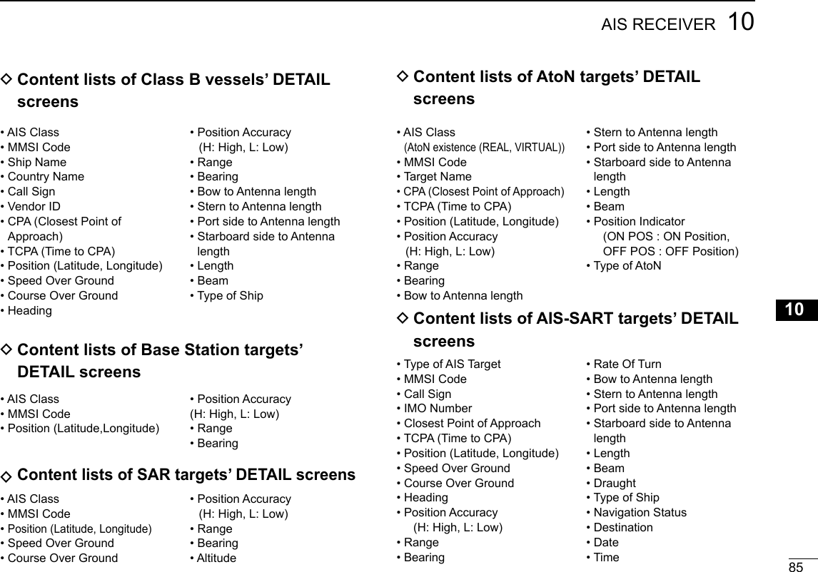
![New20018610 AIS RECEIVERNew2001 DAIS combo screenYou can display the AIS plotter during basic operation. (p XX) • Push [AIS] to display the AIS plotter on the left side of the screen. • Rotate [CH/ENT] to select an operating channel. • Push [Ω]/[≈] to select a vessel. • Push [Range] to select display range • Push [CLR] to exit the AIS combo screen. D Content lists of MOB targets’ DETAIL screens• Type of AIS Target• MMSI Code• Call Sign• IMO Number• Closest Point of Approach• TCPA (Time to CPA)• Position (Latitude, Longitude)• Speed Over Ground• Course Over Ground• Heading• Position Accuracy (H: High, L: Low)• Range • Bearing• Rate Of Turn• Bow to Antenna length• Stern to Antenna length• Port side to Antenna length• Starboard side to Antenna length• Length • Beam • Draught• Type of Ship• Navigation Status• Destination• Date• Time D Content lists of EPIRB-AIS targets’ DETAIL screens• Type of AIS Target• MMSI Code• Call Sign• IMO Number• Closest Point of Approach• TCPA (Time to CPA)• Position (Latitude, Longitude)• Speed Over Ground• Course Over Ground• Heading• Position Accuracy (H: High, L: Low)• Range • Bearing• Rate Of Turn• Bow to Antenna length• Stern to Antenna length• Port side to Antenna length• Starboard side to Antenna length• Length • Beam • Draught• Type of Ship• Navigation Status• Destination• Date• Time](https://usermanual.wiki/ICOM-orporated/388600/User-Guide-3263423-Page-86.png)
![8710AIS RECEIVERNew200112345678910111213141516 ■AIS SettingsAIS settings can be customized from “AIS Settings” on the menu screen.1. Push [MENU].2. Select“AIS SET,” then push [ENT]. DNorth up/COG UP:Select the display type for the AIS plotter. L When “N-UP” is displayed, the top of the plotter display represents North. L When “COG-UP” is displayed, the top of the plotter display represents the direction your course is heading. • Push [EXIT] to return to the Main screen. • Push [BACK] to return to the previous screen. DCPA/TCPAIn this menu, you can edit alarm settings for AIS receiver.• AlarmYou can turn the collision alarm function ON or OFF.](https://usermanual.wiki/ICOM-orporated/388600/User-Guide-3263423-Page-87.png)
![8810 AIS RECEIVERNew2001• CPA, TCPAEnter CPA (Closest Point of Approach) and TCPA (Time to CPA) values.These settings help you nd a dangerous target to avoid a collision. The icon blinks on the plotter display and/or the alarm buzzer sounds, when the AIS target is closer than your CPA and TCPA settings. z Rotate [CH/ENT] or push [Y]/[Z] to set the value. • CPA: Set between 0.1 and 6.0 nm (in 0.1 nm steps) (default: 1.5 nm) • TCPA: Set between 1 and 60 minutes (in 1 minute steps) (default: 20 min)• Slow WarnThe GPS receiver calculated COG data of a vessel that is atanchor or drifting is unreliable, and therefore the CPA and TCPA data may not be calculated correctly. If a vessel is anchored in your alarm zone, the unreliable data can cause the collision alarm to sound many times, even if there is no real danger. To prevent this, when the anchored vessel’s SOG is less than this set value, the Slow Warn function assumes that vessel’s COG is xed towards your vessel and an alarm will sound. z Rotate [CH/ENT] or push [Y]/[Z] to set the value between 0.1 and 4.9 kt (in 0.1 kt steps), or select OFF. (default: 1.0 kt)NOTE: If other vessels at anchor or drifting come into your alarm zone, the Slow Warn alarm will sound again. Only if the previous vessel disappears from the Danger List (p. 84), and then re-enters the list, can a new Slow Warn or regular alarm sound, depending on the vessels SOG, or CPA and TCPA. The Slow Warn function operates in the same way if your vessel is at anchor and other vessels enter your alarm zone area. DCPA/TCPA (Continued)](https://usermanual.wiki/ICOM-orporated/388600/User-Guide-3263423-Page-88.png)
![8910AIS RECEIVERNew200112345678910111213141516 DID BLOCKINGThe transceiver blocks AIS transponders that are entered into the ID blocking list. Enter your vessel’s transponder ID or other vessel’s transponder IDs if necessary to prevent the transceiver from detecting them as dangerous targets.You can enter maximum of 10 transponder IDs.• Entering an ID1. Push [MENU].2. Select “ID Blocking,” then push [ENT]. (AIS Settings > ID Blocking) • The blocked AIS transponder’s ID is displayed. • “No ID” is displayed if there are no blocked AIS transponders3. Push [Add] to start the ID entry +PushRotate4. Push [Finish] to enter the ID.• Editing an ID1. Push [MENU].2. Select “ID Blocking,” then push [ENT]. (AIS Settings > ID Blocking)3. Select the ID to edit, then push [EDIT].4. After editing, push [Finish] to set it.• Deleting an ID1. Push [MENU].2. Select “ID Blocking,” then push [ENT]. (AIS Settings > ID Blocking)3. Select th ID to delete, then push [Delete].](https://usermanual.wiki/ICOM-orporated/388600/User-Guide-3263423-Page-89.png)
![90New2001NMEA 2000 CONNECTION113. The transceiver starts searching the devices connected to NMEA 2000 network.4. The list of connected device is displayed.5. Select the device to send the data to transceiver and push [ENT]. • Push [INFO] to display the detail of device. • If the transceiver is connected to both NMEA 0183 and NMEA 2000 devices, the NMEA 2000 device has priority. Select “Not Used” if you want to use NMEA 0183 devices.6. Push [EXIT] to return to the Main screen.New2001 ■DescriptionNMEA 2000 is a communication standard used to connect various marine devices and display units in the vessel. The IC-M506 can easily connect to a NMEA 2000 network with its plug-and-play functionality, and display the information provided from the devices on the network. DNMEA 2000 settingsSelect the sensors in NMEA 2000 network which sends data to the transceiver. 1. P u s h [ M E N U ] .2. Select “NMEA 2000,” then push [ENT]. (NMEA Settings > NMEA 2000) Select the type of data from the menu screen and push [ENT].](https://usermanual.wiki/ICOM-orporated/388600/User-Guide-3263423-Page-90.png)
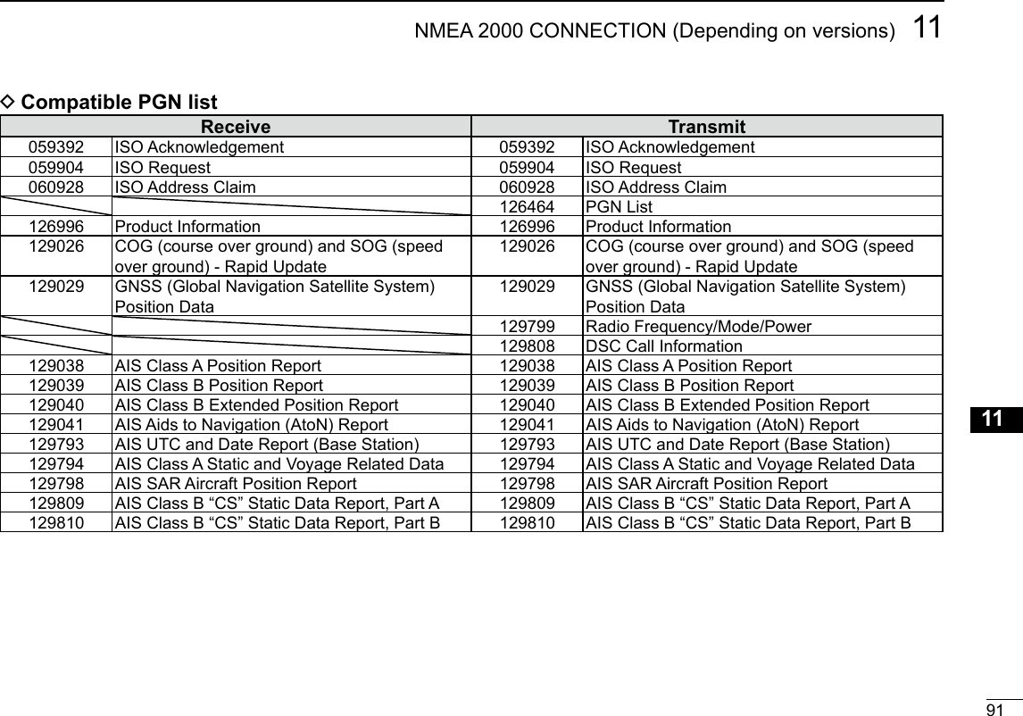
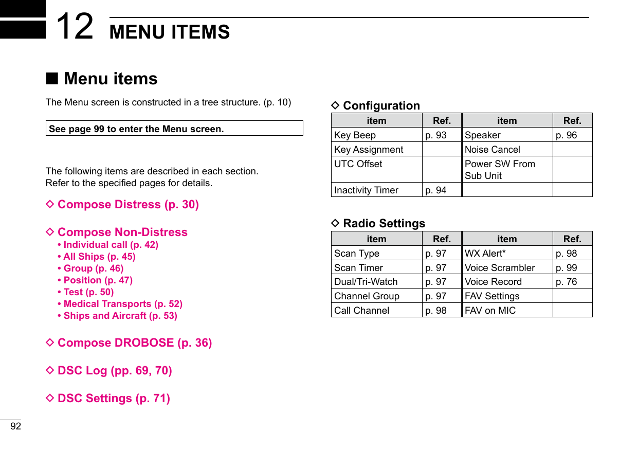
![9312MENU ITEMSNew200112345678910111213141516New2001 ■Conguration DKey Beep (Conguration > Key Beep:)Turn the Key Beep function ON or OFF.• On: Sounds a beep when pushing a key. (Default)• Off: Does not sound a beep when pushing a key for silent operation. DKey Assignment (Conguration > Key Assignment:)Assign functions to Software keys. The assigned function can be used when its key icon is displayed.See page XX for details of the assignable key functions.1. Select the Software key, then push [ENT].2. Select the function to assign, then push [ENT].](https://usermanual.wiki/ICOM-orporated/388600/User-Guide-3263423-Page-93.png)
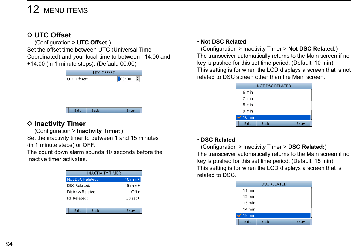
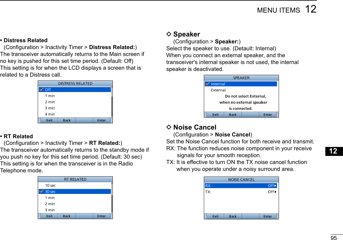
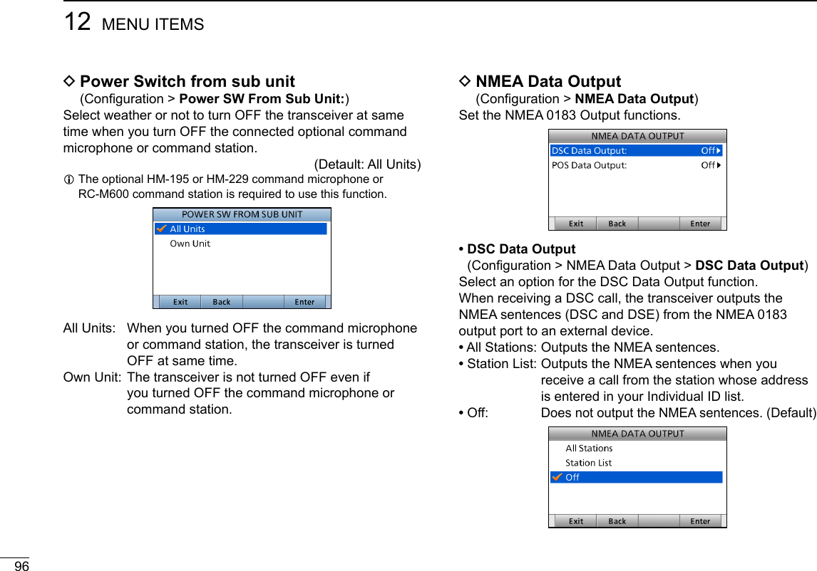
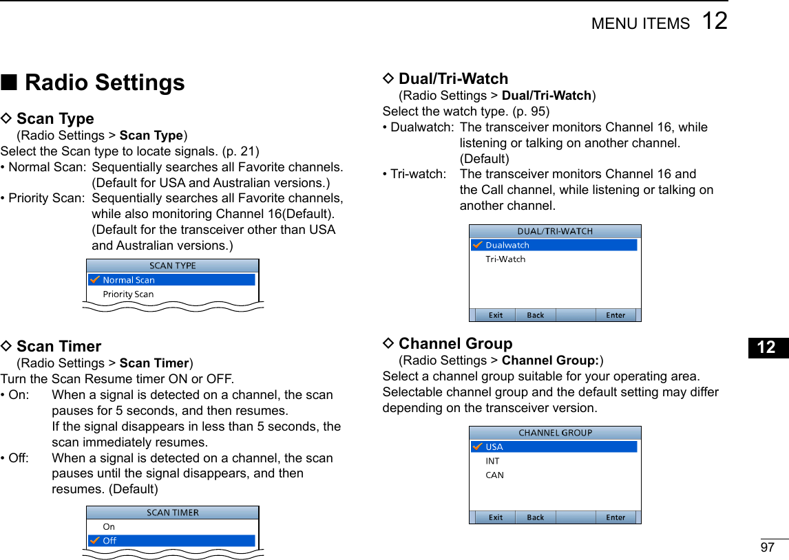
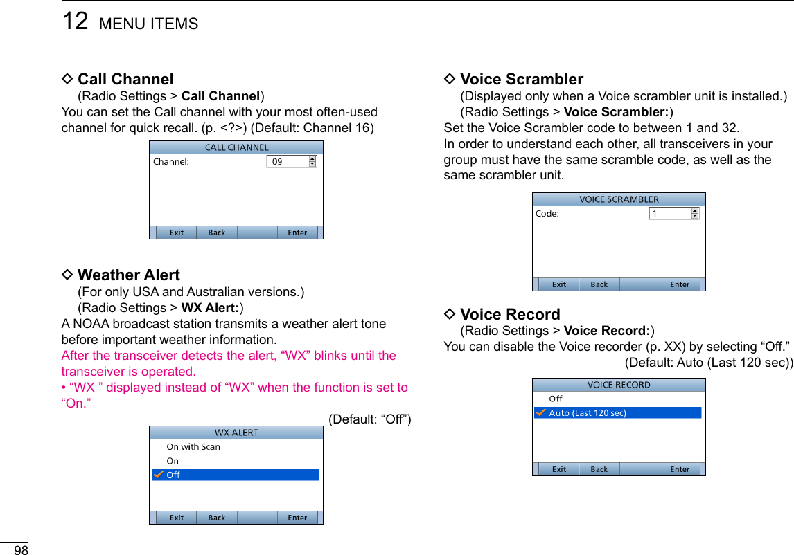
![9912MENU ITEMSNew200112345678910111213141516 DFAV Settings (Radio Settings > FAV Settings)Set the Favorite channel settings.• Set All Channels: Sets all channels as Favorite channels.• Clear All Channels: Clears all Favorite channels.• Set Default: Returns to the default setting. DFAV on MIC (Radio Settings > FAV on MIC)Turn the FAV on MIC function ON or OFF.• On: Pushing [∫] or [√] on the supplied microphone scrolls up and down through only the Favorite channels. (Default)• Off: Pushing [∫] or [√] on the supplied microphone scrolls up and down through all channels.](https://usermanual.wiki/ICOM-orporated/388600/User-Guide-3263423-Page-99.png)
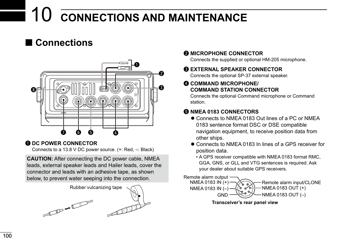
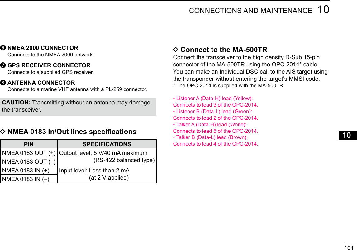
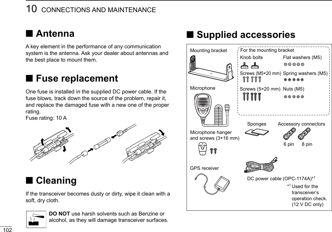
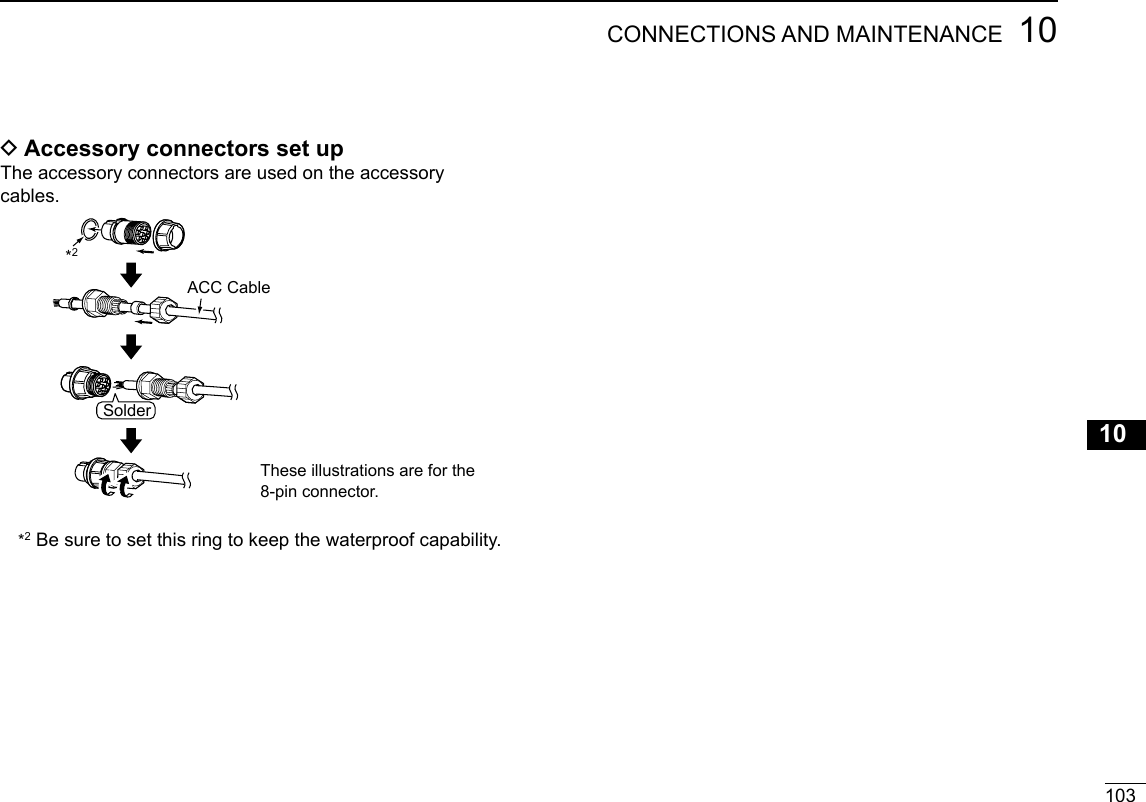
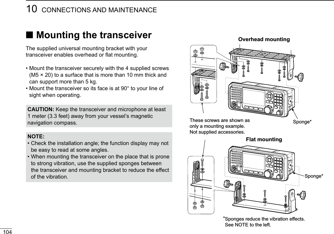
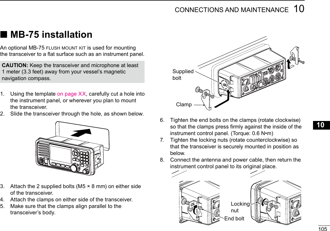
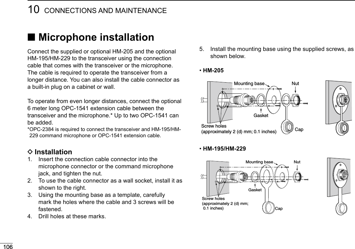
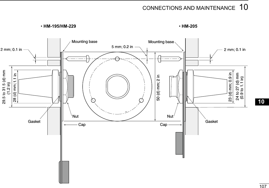
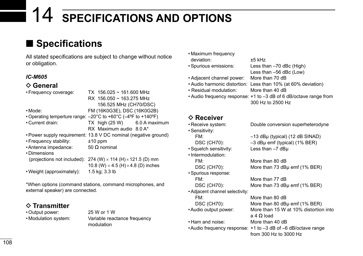
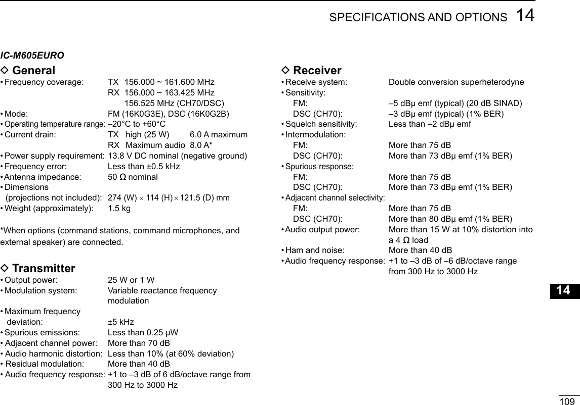
![New200111014 SPECIFICATIONS AND OPTIONSNew2001 ■Options DCommand stations and cables •RC-M600 command stationThe command station with the same front panel as the transceiver. Mounting bracket , microphone, and 10 meter (32.8 feet) connection cable included. •OPC-2383 xxxxxxxx10 meter (32.8 feet) cable to connect the transceiver and RC-M600 command station. •OPC-2377 xxxxxxxx10 meter (32.8 feet) extension cable. DMicrophone and cables •HM-195B/HM-195SW commandmicIV™External microphone-type controller. Provides optional intercom operation. 6 meters (20 feet) microphone cable and mounting base included.HM-195B: BlackHM-195SW: Super White •HM-229B/HM-229W commandmicV™External microphone-type controller without [DISTRESS] key.HM-229B: BlackHM-229W: White DDimensions Unit: mm (inch)274 (10.8)114 (4.5) 121.5 (4.8)250 (9.8)148.25 (5.8)28 (1.1) 93.5 (3.7)93.75 (3.7)](https://usermanual.wiki/ICOM-orporated/388600/User-Guide-3263423-Page-110.png)
![11114SPECIFICATIONS AND OPTIONSNew200112345678910111213141516New2001 •OPC-2384 xxxxxxxxxxxxxThe cable to connect the transceiver and HM-195 or HM-229. •OPC-1541 microphone extension cable6 meters (20 feet) microphone extension cable for optional HM-195 commandmicIV™. Up to two OPC-1541 can be connected. Usable length is 18 meters (60 feet) maximum. •HM-205B/HM-205RB speaker microphoneEquipped with [Y]/[Z] (channel up/down), [H/L], [16/C], and [PTT] keys, a speaker and microphone. DOthers •SP-37 horn speakerThe external horn speaker. Connect using the supplied 6 pin accessory connector that supplied with the transceiver. •MA-500TR class b ais transponderTo transmit individual DSC calls to a selected AIS targets. •MB-75 flush mount kitTo mount the transceiver to a panel. •UX-241 gnss antennaTo receive the GPS signal. •UT-112 voice scrambler unitEnsures private communications. 32 codes are available.Not available in some countries.Ask your service center or technical dealer for installation details. •UT-251 ais receiver unitThe optional AIS unit for the version without AIS function.Ask your service center or technical dealer for installation details.](https://usermanual.wiki/ICOM-orporated/388600/User-Guide-3263423-Page-111.png)
![New2001112New2001TROUBLESHOOTING15New2001PROBLEM POSSIBLE CAUSE SOLUTION REF.The transceiver does not turn ON.• Bad connection to the power supply.• Fuse blows.• Check the connection to the transceiver and power supply.• Repair the problem, and then replace the fuse.p. 86p. 84Little or no sound comes from the speaker.• Squelch level is set too high.• Volume level is set too low.• The internal speaker is OFF.• Set the squelch to the threshold point.• Set the volume to a suitable level.• Turn ON the internal speaker.p. 15p. 15p. 81You cannot transmit, or cannot select high power.• Some channels are set for low power or receive only by regulations.• The output power is set to low.• Change channels.• Push [HI/LO] to select high power.pp. 13 93p. 15Scan does not start. • More than 2 favorite channels are not set. • Set the desired channels as Favorite channels.pp. 21, 78No beep sounds. • The Key Beep function is OFF.• Turn ON the Key Beep function.p. 78The Main screen is not displayed at power ON.• MMSI (DSC self ID) code is not set. • Set the MMSI (DSC self ID) code. p. 9Individual or Group ID cannot be set.• The entered ID code is incorrect. First digit must be set to between ʻ1ʼ and ʻ9ʼ for the Individual ID. First digit must be set to ʻ0ʼ for the Group ID.• Enter a correct ID code. pp. 23, 24“??” blinks instead of the position and time.• 4 hours have passed after you manually entered the position.• The GPS position is invalid.• Enter the position. p. 25](https://usermanual.wiki/ICOM-orporated/388600/User-Guide-3263423-Page-112.png)