ICOM orporated 388600 VHF Marine Transceiver User Manual
ICOM Incorporated VHF Marine Transceiver
User Manual

INSTRUCTION MANUAL
VHF MARINE TRANSCEIVERS
iM605EURO
iM605
• This device complies with Part 15 of the FCC Rules. Operation is
subject to the condition that this device does not cause harmful
interference.
• This device complies with the GMDSS provisions of Part 80 of the FCC
Rules.

ii
Thank you for choosing this Icom product.
This product is designed and built with Icom’s state of the art
technology and craftsmanship.
With proper care, this product should provide you with years
of trouble-free operation.
The IC-M605/IC-M605EURO vhf marine transceiver has
DSC functions for distress alert transmission and reception,
as well as the general DSC calls (Individual calls, All Ships
calls, Group calls, and so on).
IMPORTANT
READ ALL INSTRUCTIONS carefully and completely
before using the transceiver.
SAVE THIS INSTRUCTION MANUAL — This instruction
manual contains important operating instructions for the
IC-M605/IC-M605EURO.
Icom, Icom Inc. and Icom logo are registered trademarks of Icom Incorporated
(Japan) in Japan, the United States, the United Kingdom, Germany, France,
Spain, Russia, Australia, New Zealand, and/or other countries.
AquaQuake™ is a trademark of Icom Incorporated.
EXPLICIT DEFINITIONS
WORD DEFINITION
RWARNING! Personal injury, re hazard or electric
shock may occur.
CAUTION Equipment damage may occur.
NOTE If disregarded, inconvenience only. No risk
of personal injury, re or electric shock.
CLEAN THE FRONT PANEL THOROUGHLY WITH FRESH
WATER after exposure to saltwater, and dry it before
operating. Otherwise, the front panel’s keys, switches and
controllers may become unusable, due to salt crystallization.
NOTE: If the front panel’s waterproof protection appears
defective, carefully clean it with a soft, wet (fresh water)
cloth, then, dry it before operating.
The front panel may lose its waterproof protection if the
case or connector cover is cracked or broken, or the
transceiver has been dropped.
Icom is not responsible for the destruction, damage to, or
performance of any Icom or non-Icom equipment, if the
malfunction is because of:
• Force majeure, including, but not limited to, res,
earthquakes, storms, oods, lightning, other natural
disasters, disturbances, riots, war, or radioactive
contamination.
• The use of Icom transceivers with any equipment that is
not manufactured or approved by Icom.

IN CASE OF EMERGENCY
If your vessel requires assistance, contact other vessels and
the Coast Guard by sending a Distress call on Channel 16.
USING CHANNEL 16
DISTRESS CALL PROCEDURE
1. “MAYDAY MAYDAY MAYDAY.”
2. “THIS IS ...............” (name of vessel).
3. Say your call sign or other description of the vessel
(AND 9 digit DSC ID if you have one).
4. “LOCATED AT ...............” (your position).
5. State the nature of the distress and assistance required.
6. Give any other information which might facilitate the
rescue.
Or, transmit your Distress call using Digital Selective Calling
on Channel 70.
USING DIGITAL SELECTIVE CALLING (Ch 70)
DISTRESS CALL PROCEDURE
1. While lifting up the key cover, hold down [DISTRESS]
for 3 seconds until you hear 3 short beeps and then
one long beep.
2. Wait for an acknowledgment on Channel 70 from a
coast station.
• After the acknowledgement is received, Channel 16 is
automatically selected.
3. Hold down [PTT], then transmit the appropriate
information as listed above. ii
INSTALLATION NOTE
Installation:
The installation of this equipment should be made in such a
manner as to respect the EC recommended electromagnetic
eld exposure limits. (1999/519/EC)
The maximum RF power available from this device is 25
watts. The antenna should be installed as high as possible
for maximum efciency and the installation height should be
at least 1.76 meters above any accessible position. In the
case where an antenna cannot be installed at a reasonable
height, then the transmitter should neither be continuously
operated for long periods if any person is within a distance
of 1.76 meters of the antenna, nor operated at all if any
person is touching the antenna.
It is recommended that antenna of a maximum gain of
3 dB is used. If higher gain antenna are required then
please contact your Icom distributor for revised installation
recommendations.
Operation:
The exposure to RF electromagnetic eld is only applicable
when this device is transmitting. This exposure is naturally
reduced due to the nature of alternating periods of receiving
and transmitting. Keep your transmissions to the minimum
necessary.

iii
New2001
WARNING
Icom requires the radio operator to meet the FCC
Requirements for Radio Frequency Exposure. An
omnidirectional antenna with gain not greater than 9
dBi must be mounted a minimum of 5 meters
(measured from the lowest point of the antenna)
vertically above the main deck and all possible
personnel. This is the minimum safe separation distance estimated
to meet all RF exposure compliance requirements. This 5 meter
distance is based on the FCC Safe Maximum Permissible Exposure
(MPE) distance of 3 meters added to the height of an adult (2
meters) and is appropriate for all vessels.
For watercraft without suitable structures, the antenna must be
mounted so as to maintain a minimum of 1 meter vertically between
the antenna, (measured from the lowest point of the antenna), to
the heads of all persons AND all persons must stay outside of the 3
meter MPE radius.
Do not transmit with radio and antenna when persons are within the
MPE radius of the antenna, unless such persons (such as driver
or radio operator) are shielded from antenna eld by a grounded
metallic barrier. The MPE Radius is the minimum distance from
the antenna axis that person should maintain in order to avoid RF
exposure higher than the allowable MPE level set by FCC.
FAILURE TO OBSERVE THESE LIMITS MAY ALLOW THOSE
WITHIN THE MPE RADIUS TO EXPERIENCE RF RADIATION
ABSORPTION WHICH EXCEEDS THE FCC MAXIMUM
PERMISSIBLE EXPOSURE (MPE) LIMIT.
IT IS THE RESPONSIBILITY OF THE RADIO OPERATOR TO
ENSURE THAT THE MAXIMUM PERMISSIBLE EXPOSURE
LIMITS ARE OBSERVED AT ALL TIMES DURING RADIO
TRANSMISSION. THE RADIO OPERATOR IS TO ENSURE
THAT NO BYSTANDERS COME WITHIN THE RADIUS OF THE
MAXIMUM PERMISSIBLE EXPOSURE LIMITS.
Determining MPE Radius
THE MAXIMUM PERMISSIBLE EXPOSURE (MPE) RADIUS HAS
BEEN ESTIMATED TO BE A RADIUS OF ABOUT 3M PER OET
BULLETIN 65 OF THE FCC.
THIS ESTIMATE IS MADE ASSUMING THE MAXIMUM POWER
OF THE RADIO AND ANTENNAS WITH A MAXIMUM GAIN OF
9dBi ARE USED FOR A SHIP MOUNTED SYSTEM.
RADIO OPERATOR WARNING

iv
New2001
Icom exige que l'opérateur radio se conforme aux
exigences de la FCC en matière d'exposition aux
radiofréquences. Une antenne omnidirectionnelle
dont le gain ne dépasse pas 9dBi doit être
xée à une distance minimale de 5 mètres
(mesurée depuis le point le plus bas de l'antenne)
verticalement au-dessus du pont principal et de tout le personnel qui
peut s'y trouver. Il s'agit de la distance de sécurité minimale prévue
pour satisfaire aux exigences de conformité en matière d'exposition
aux RF. Cette distance de 5 mètres est établie en fonction de
l'exposition maximale admissible sécuritaire de 3 mètres établie par
la FCC, à laquelle on ajoute la hauteur d'un adulte (2 mètres); cette
distance convient pour tous les navires.
Dans le cas des embarcations sans structure convenable, l'antenne
doit être xée de façon à maintenir une distance minimale de 1 mètre
verticalement entre cette antenne (mesurée depuis son point le plus
bas) et la tête de toute personne présente; toutes les personnes
présentes doivent se tenir à l'extérieur d'un rayon d'exposition
maximale admissible de 3 mètres.
Ne pas émettre à l'aide de la radio et de l'antenne lorsque des
personnes se trouvent à l'intérieur du rayon d'exposition maximale
admissible de cette antenne, à moins que ces personnes (comme
le conducteur ou l'opérateur radio) ne soient protégées du champ
de l'antenne par un écran métallique relié à la masse. Le rayon
d'exposition maximale admissible équivaut à la distance minimale
que cette personne doit maintenir entre elle et l'axe de l'antenne
pour éviter une exposition aux RF supérieure au niveau d'exposition
maximale admissible xé par la FCC.
LE NON-RESPECT DE CES LIMITES PEUT CAUSER,
POUR LES PERSONNES SITUÉES DANS LE RAYON
D'EXPOSITION MAXIMALE ADMISSIBLE, UNE ABSORPTION
DE RAYONNEMENT DE RF SUPÉRIEURE À L'EXPOSITION
MAXIMALE ADMISSIBLE FIXÉE PAR LA FCC.
L'OPÉRATEUR RADIO EST RESPONSABLE D'ASSURER QUE
LES LIMITES D'EXPOSITION MAXIMALE ADMISSIBLE SOIENT
RESPECTÉES EN TOUT TEMPS PENDANT LA TRANSMISSION
RADIO. L'OPÉRATEUR RADIO DOIT S'ASSURER QU'AUCUNE
PERSONNE PRÉSENTE NE SE SITUE À L'INTÉRIEUR DU
RAYON D'EXPOSITION MAXIMALE ADMISSIBLE.
Établir le rayon d'exposition maximale admissible
ON ESTIME QUE LE RAYON D'EXPOSITION MAXIMALE
ADMISSIBLE EST D'ENVIRON 3 M, TEL QUE STIPULÉ DANS
LE BULLETIN OET 65 DE LA FCC. CETTE DISTANCE ESTIMÉE
TIENT COMPTE D'UN SYSTÈME INSTALLÉ SUR UN NAVIRE
UTILISANT LA PUISSANCE MAXIMALE DE LA RADIO ET DES
ANTENNES DONT LE GAIN MAXIMAL EST DE 9dBi.
AVERTISSEMENT POUR LES OPÉRATEURS RADIO
AVERTISSEMENT
v
FCC INFORMATION
• FOR CLASS A UNINTENTIONAL RADIATORS:
This equipment has been tested and found to comply with
the limits for a Class A digital device, pursuant to part 15
of the FCC Rules. These limits are designed to provide
reasonable protection against harmful interference when the
equipment is operated in a commercial environment. This
equipment generates, uses, and can radiate radio frequency
energy and, if not installed and used in accordance with the
instruction manual, may cause harmful interference to radio
communications.
Operation of this equipment in a residential area is likely to
cause harmful interference in which case the user will be
required to correct the interference at his own expense.
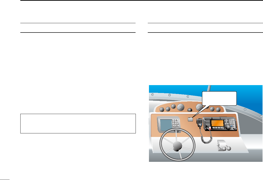
NOTE
A WARNING STICKER is supplied with the USA version
transceiver.
To comply with FCC regulations, this sticker must be afxed
in such a location as to be readily seen from the operating
controls of the radio as in the diagram below. Make sure the
chosen location is clean and dry before applying the sticker.
EXAMPLE
CAUTION: Changes or modications to this device, not
expressly approved by Icom Inc., could void your authority
to operate this device under FCC regulations.
WARNING
STICKER

vi
New2001
PRECAUTIONS
RWARNING! NEVER
connect the transceiver to an AC outlet.
This may pose a re hazard or result in an electric shock.
RWARNING! NEVER connect the transceiver to a power
source of more than 16 V DC such as a 24 V battery. This
could damage the transceiver.
RWARNING! NEVER reverse the DC power cable polarity
when connecting to a power source. This could damage the
transceiver.
RWARNING! NEVER cut the DC power cable between the
DC plug at the back of the transceiver and the fuse holder. If
an incorrect connection is made after cutting, the transceiver
may be damaged.
RWARNING! NEVER operate the transceiver during a
lightning storm. It may result in an electric shock, cause a
re or damage the transceiver. Always disconnect the power
source and antenna before a storm.
RWARNING!
NEVER
place the transceiver where normal
operation of the vessel may be hindered, or where it could
cause bodily injury.
CAUTION: KEEP the transceiver and microphone at least 1
meter away from the vessel’s magnetic navigation compass.
CAUTION: DO NOT place or leave the transceiver in areas
with temperatures below –15°C or above +55°C, or in areas
subject to direct sunlight, such as a dashboard.
CAUTION: DO NOT use harsh solvents such as Benzine
or alcohol to clean the transceiver, as they will damage the
transceiver’s surfaces. If the transceiver becomes dusty or
dirty, wipe it clean with a soft, dry cloth.
BE CAREFUL! The transceiver rear panel will become hot
when transmitting continuously for long periods of time.
Place the transceiver in a secure place to avoid inadvertent
use by unauthorized persons.
BE CAREFUL! The transceiver’s front panel meets IPX7*
requirements for waterproof protection. However, once
the transceiver has been dropped, or the waterproof seal
is cracked or damaged, waterproof protection cannot be
guaranteed because of possible damage to the case or the
waterproof seal.
*The connectors on the rear panel do not meet IPX7.

vii
New2001
PRÉCAUTIONS
RAVERTISSEMENT ! NE JAMAIS relier l'émetteur-récepteur à
une prise CA. Cela pourrait provoquer un choc électrique ou un
incendie.
RAVERTISSEMENT ! NE JAMAIS brancher l'émetteur-récepteur
sur une source d'alimentation supérieure à 16 V CC, comme une
batterie de 24 V. Cela pourrait endommager l'émetteur-récepteur.
RAVERTISSEMENT ! NE JAMAIS inverser la polarité du câble
d'alimentation CC lors de la connexion à une source d'alimentation.
Cela pourrait endommager l'émetteur-récepteur.
RAVERTISSEMENT ! NE JAMAIS couper le câble d'alimentation
CC entre la prise CC a l’arrière de l’émetteur-récepteur et le porte-
fusible. L’émetteur-récepteur peut être endommagé par la suite en
cas de connexion inappropriée.
RAVERTISSEMENT ! NE JAMAIS utiliser l'émetteur-récepteur
durant un orage. Cela risquerait de provoquer un choc électrique,
un incendie ou d'endommager l'émetteur-récepteur. Toujours
débrancher la source d'alimentation et l'antenne avant une tempête.
MISE EN GARDE : NE JAMAIS installer l’émetteur-récepteur à
un emplacement où il pourrait gêner le fonctionnement normal du
navire ou provoquer des blessures corporelles.
INSTALLER la VHF et le microphone à au moins 1 m du compas
de route du navire.
NE PAS utiliser ou placer l’émetteur-récepteur dans des zones où
la temperature est inférieure à –15° ou supérieure à +55° ou dans
des zones soumises au rayonnement solaire direct, telles le tableau
de bord.
NE PAS nettoyer l'appareil avec des solvants agressifs tels que
benzène ou alcool, susceptibles d'endommager les surfaces
exposées du boitier. En cas de dépôt de poussière ou de salissures
sur l'émetteur-récepteur, il faut l'essuyer avec chiffon doux et sec.
MISE EN GARDE ! La face arrière de la VHF chauffe en cas
d’utilisation continue sur une longue durée.
Placer l’émetteur-récepteur hors de portée des enfants pour éviter
toute utilisation inopinée.
MISE EN GARDE ! La face avant de l'émetteur-récepteur est
étanche conformément à la norme IPX7*. L’étanchéité ne peut plus
être garantie après une chute de l’appareil en raison des risques de
ssures du boîtier, de dégradation du joint d’étanchéité, etc.
*Les connecteurs sur le panneau arrière ne sont pas étanche IPX7.
Si la face avant est exposée à de l'eau de mer, ASSUREZ-VOUS
DE LE NETTOYER ENTIEREMENT AVEC DE L'EAU DOUCE
lorsque la protection étanche sur le panneau avant fonctionne.
Dans le cas contraire, les touches et le commutateur risquent de ne
plus fonctionner en raison de la cristallisation du sel.
Icom ne peut pas être tenu pour responsable de la destruction, de la
détérioration ou des performances d'un équipement Icom ou non-Icom,
si le dysfonctionnement survient à cause de :
• Force majeure, sans toutefois s'y limiter, les incendies, tremblements de
terre, tempêtes, inondations, la foudre, d'autres catastrophes naturelles,
perturbations, émeutes, guerre, ou contamination radioactive.
• L'utilisation d'un émetteur-récepteur Icom avec tout équipement non
fabriqué ou approuvé par Icom.
viii
New2001
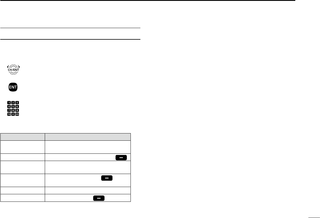
ACTION ICON DESCRIPTION
The following describes the [CH/ENT], [ENT] and the
keypad operations in this instruction manual.
: Push [ENT] to enter or set.
Push
: Push the keypad to enter
a digit or text.
Push
Rotate
: Rotate [CH/ENT] to select.
Also, you can use the following key functions in the Menu
screen.
FUNCTION ACTION
Select Rotate [CH/ENT].
Push [∫] or [√].
Enter Push [ENT], [CH/ENT], or [Enter] .
Go to the next tree
level
Push [ENT] or [≈].
Go back to the
previous tree level
Push [CLR], [Ω], or [Back] .
Cancel Push [CLR].
Exit Push [MENU] or [Exit] .

ix
New2001
TABLE OF CONTENTS
IMPORTANT ......................................................................................i
EXPLICIT DEFINITIONS ...................................................................i
DISPOSAL ......................................................................................... i
IN CASE OF EMERGENCY ............................................................. ii
INSTALLATION NOTE ..................................................................... ii
PRECAUTIONS ................................................................................iii
COUNTRY CODE LIST ................................................................... iv
ACTION ICON DESCRIPTION ....................................................... iv
1 OPERATING RULES ..................................................................1
2 PANEL DESCRIPTION ........................................................... 2–8
■Front panel ..............................................................................2
■Software key function ..............................................................5
■Speaker Microphone ...............................................................5
■Function display (Main screen) ............................................... 6
3 PREPARATION ...........................................................................9
■Entering the MMSI code .........................................................9
4 MENU SCREEN .................................................................. 10–12
■Construction ..........................................................................10
■Selecting a Menu item ..........................................................12
5 BASIC OPERATION ...........................................................13–19
■Selecting a channel ...............................................................13
■ Setting the Call channel ........................................................ 14
■Receiving and transmitting ....................................................15
■Backlight function ..................................................................17
■ Microphone Lock function ..................................................... 17
■Entering a Channel name .....................................................18
5 SCAN OPERATION ............................................................20–21
■Scan types ............................................................................20
■Favorite channels ..................................................................21
■Starting a scan ...................................................................... 21
6 DUALWATCH/TRI-WATCH ....................................................... 22
■Description ............................................................................ 22
■Operation ..............................................................................22
7 DSC OPERATION ...............................................................23–75
■DSC address ID .................................................................... 23
■Entering the position and time ..............................................25
■DSC Task mode .................................................................... 27
■Sending a Distress call .........................................................29
■Sending a Non-Distress call ..................................................42
■Receiving DSC calls .............................................................54
■Received Call log .................................................................. 69
■Transmitted Call log ..............................................................70
■DSC Settings ........................................................................71
8 MENU ITEMS ...................................................................... 76–81
■Menu items ...........................................................................76
■Radio Settings .......................................................................77
■Conguration .........................................................................78
9 CONNECTIONS AND MAINTENANCE ..............................82–88
■Connections .......................................................................... 82
■Antenna .................................................................................84
■Fuse replacement .................................................................84
■Cleaning ................................................................................84
■Supplied accessories ............................................................ 85
■Power source connections ....................................................86
■Mounting the transceiver .......................................................87
■Handset (HS-98) ................................................................... 88
10 SPECIFICATIONS AND OPTIONS .....................................89–90
■Specications ........................................................................89
■Options ..................................................................................90
11 TROUBLESHOOTING ........................................................ 91–92
12 CHANNEL LIST ........................................................................93
13 DIGITAL INTERFACE (IEC 61162-1) ..................................94–97
■I/O Sentences .......................................................................94
■Schematic diagram ...............................................................97
■Hardware version ..................................................................97
■Software version ...................................................................97
INDEX.....................................................................................98–100

1
1
OPERATING RULES
New2001
1
2
3
4
5
6
7
8
9
10
11
12
13
14
15
16
DPriorities
• Read all rules and regulations pertaining to call priorities,
and keep an up-to-date copy handy. Safety and distress
calls take priority over all others.
• You must monitor Channel 16 when you are not operating
on another channel.
• False or fraudulent distress calls are prohibited under law.
DPrivacy
• Information overheard, but not intended for you, cannot
lawfully be used in any way.
• Indecent or profane language is prohibited.
DRadio licenses
(1) SHIP STATION LICENSE
You may require a current radio station license before using
the transceiver. It is unlawful to operate a ship station which
is not licensed, but required to be.
If required, contact your dealer or the appropriate
government agency for a Ship-Radiotelephone license
application. This government-issued license states the call
sign which is your craft’s identication for radio purposes.
(2) OPERATOR’S LICENSE
A Restricted Radiotelephone Operator Permit is the license
most often held by small vessel radio operators when a
radio is not required for safety purposes.
If required, the Restricted Radiotelephone Operator Permit
must be posted or kept with the operator. If required, only a
licensed radio operator may operate a transceiver.
However, non-licensed individuals may talk over a
transceiver if a licensed operator starts, supervises, ends
the call and makes the necessary log entries.
A current copy of the applicable government rules and
regulations is only required to be on hand for vessels in
which a radio telephone is compulsory. However, even
if you are not required to have these on hand it is your
responsibility to be thoroughly acquainted with all pertinent
rules and regulations.
NOTE: Even though the transceiver is capable of operation
on VHF marine channels 3, 21, 23, 61, 64, 81, 82 and
83, according to FCC regulations these simplex channels
cannot be lawfully used by the general population in USA
waters.
New2001
2
New2001
PANEL DESCRIPTION
2
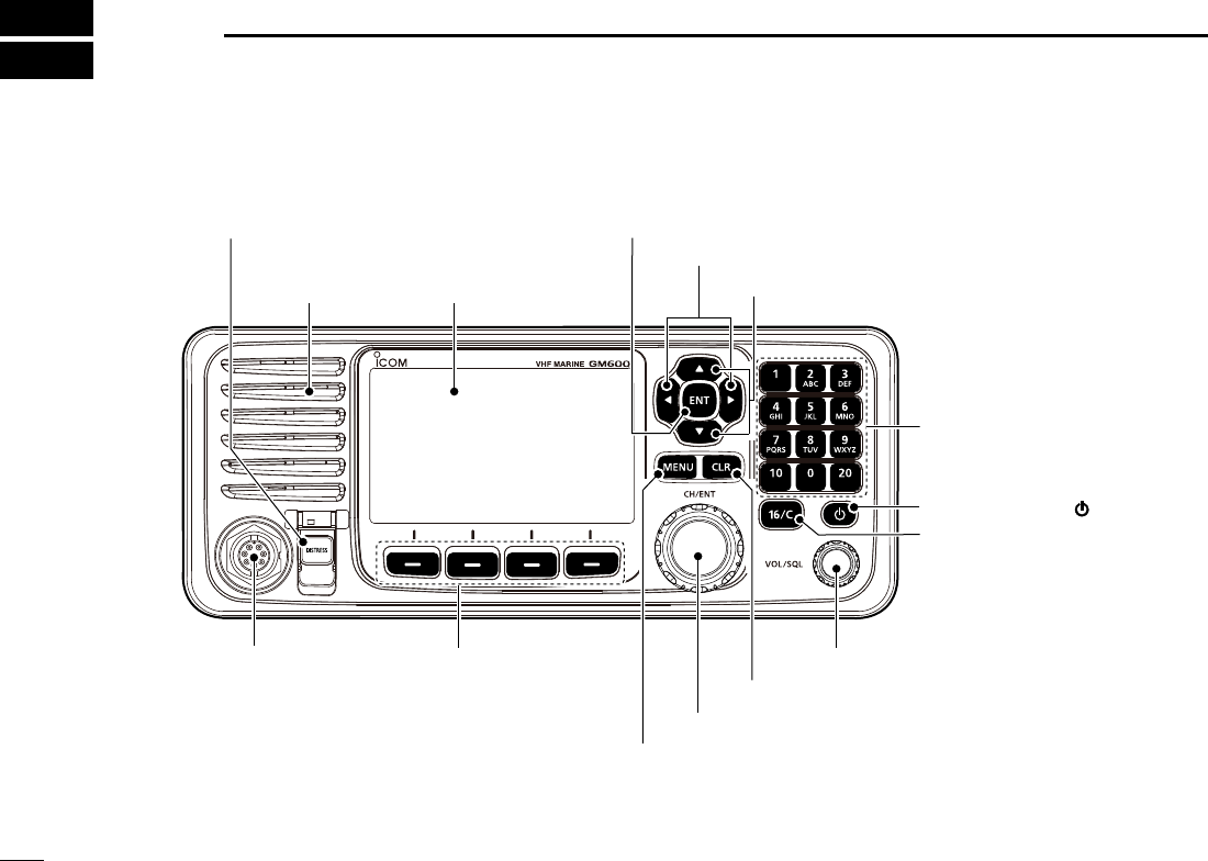
■Front panel
q DISTRESS KEY [DISTRESS]
!1 MENU KEY [MENU]
Speaker Function display (p. ?)
w ENTER KEY [ENT]
e LEFT AND RIGHT KEYS [Ω]/[≈]
r
UP AND DOWN KEYS [∫]/[√]
t KEYPAD
y POWER KEY [ ]
u CHANNEL 16/
CALL CHANNEL KEY [16/C]
i VOLUME/SQUELCH DIAL [VOL/SQL]
o CLEAR KEY [CLR]
!0 CHANNEL SELECTOR/ENTER SWITCH [CH/ENT]
!2
SOFTWARE KEYS
MIC CONNECTOR

New2001
3
2
PANEL DESCRIPTION
New2001
1
2
3
4
5
6
7
8
9
10
11
12
13
14
15
16
q DISTRESS KEY [DISTRESS] (p. ?)
Hold down for 3 seconds to transmit a Distress call.
w ENTER KEY [ENT]
Push to set the entered data, selected item, and so on.
e LEFT AND RIGHT KEYS [◄]/[►]
z Push to scroll the Software Key functions. (p. ?)
z In the character or number entry mode, push to select
a character or number in the keypad.
(p. ?)
r
UP AND DOWN/CHANNEL SELECT KEYS [
▲
]/[
▼
]
z Push to select an operating channel (p. ?), Menu items
(p. ?), Menu settings (p. ?), and so on.
z While scanning, push to check the Favorite channels,
change the scanning direction or manually resume a
scan. (p. ?)
t KEYPAD
Push to enter numbers, letters or symbols.
For channel number entry, see page ?.
For channel name entry, see page ?.
y POWER KEY [ ]
Hold down for 1 second to turn the transceiver ON or
OFF.
u CHANNEL 16/CALL CHANNEL KEY [16/C]
z Push to select Channel 16. (p. ?)
z
Hold down for 1 second to select the Call channel.(p. ?)
• “CALL” is displayed when the Call channel is selected.
i VOLUME/SQUELCH DIAL [VOL/SQL] (p. ?)
z Rotate to adjust the volume level.
z Push once or twice to display the Volume or Squelch
Setting screen, and then rotate to adjust the volume or
squelch level.
o CLEAR KEY [CLR]
Push to cancel the entered data, or to return to the
previous screen.
!0 CHANNEL SELECTOR/ENTER SWITCH [CH/ENT]
z Rotate to select an operating channel (p. ?), Menu
items (p. ?), or Menu settings (p. ?).
z Push to set the entered data, or selected item. (p. ?)
!1 MENU KEY [MENU]
Push to enter or exit the Menu screen.
(p. ?)

4
2PANEL DESCRIPTION
New2001 New2001
■Front panel (Continued)
!2 SOFTWARE KEYS (p. ?)
You can use various key functions that are assigned to
the Software Keys, as described below.
Compose Distress* (p. ?)
Push to display the COMPOSE DISTRESS screen.
Compose Others* (p. ?)
Push to display the COMPOSE NON-DISTRESS screen.
Task List (p. ?)
When the transceiver has any task, push to enter the
Task mode.
Scan (p. ?)
Push to start or stop a Normal or Priority scan.
Dualwatch/Tri-watch [DW/TW] (p. ?)
Push to start or stop the Dualwatch or Tri-watch.
AIS (p. ?)
Push to display the AIS plotter on the left side of the
display.
L An AIS receiver may not be installed, depending on the
transceiver version.
Channel/ Wheather [CH/WX] (p. ?)
(For only the USA and AUS versions.)
Push to select either the regular channels or the Weather
channels.
Channel [CHAN] (p. ?)
(For only the versions except the USA and AUS versions. )
Push to enter the regular channel selection mode.
High/Low [HI/LO] (p. ?)
Push to set the output power level to high or low.
LSome channels are set to only low power.
Voice Scrambler (p. ?)
Push to set the Voice Scrambler function.
L This functions is displayed only when the voice scrambler unit
is installed.
RX Play (p. ?)
Push to play recorded audio.
* These key functions are not displayed in the Radio Telephone (RT) mode. (p. ?)
RX Hailer (p. ?)
Push to turn the RX Hailer mode ON or OFF.
LO/DX (p. ?)
Push to turn the Attenuator function ON or OFF.
LThe “LOC” icon appears when the Attenuator function is ON.
Favorite channel [Favorite] (p. ?)
z Push to set or clear the displayed channel as a
Favorite channel.
z Hold down for 3 seconds to clear or set all Favorite
channels in the selected channel group.
Channel Name (p. ?)
Push to display the CHANNEL NAME screen.
DSC Log (p. ?)
Push to display the Received Call Log (RCVD CALL
LOG) screen.
Backlight (p. ?)
Push to open the Backlight Settings window.
New2001
5
2
PANEL SCRIPTION
1
2
3
4
5
6
7
8
9
10
11
12
13
14
15
16
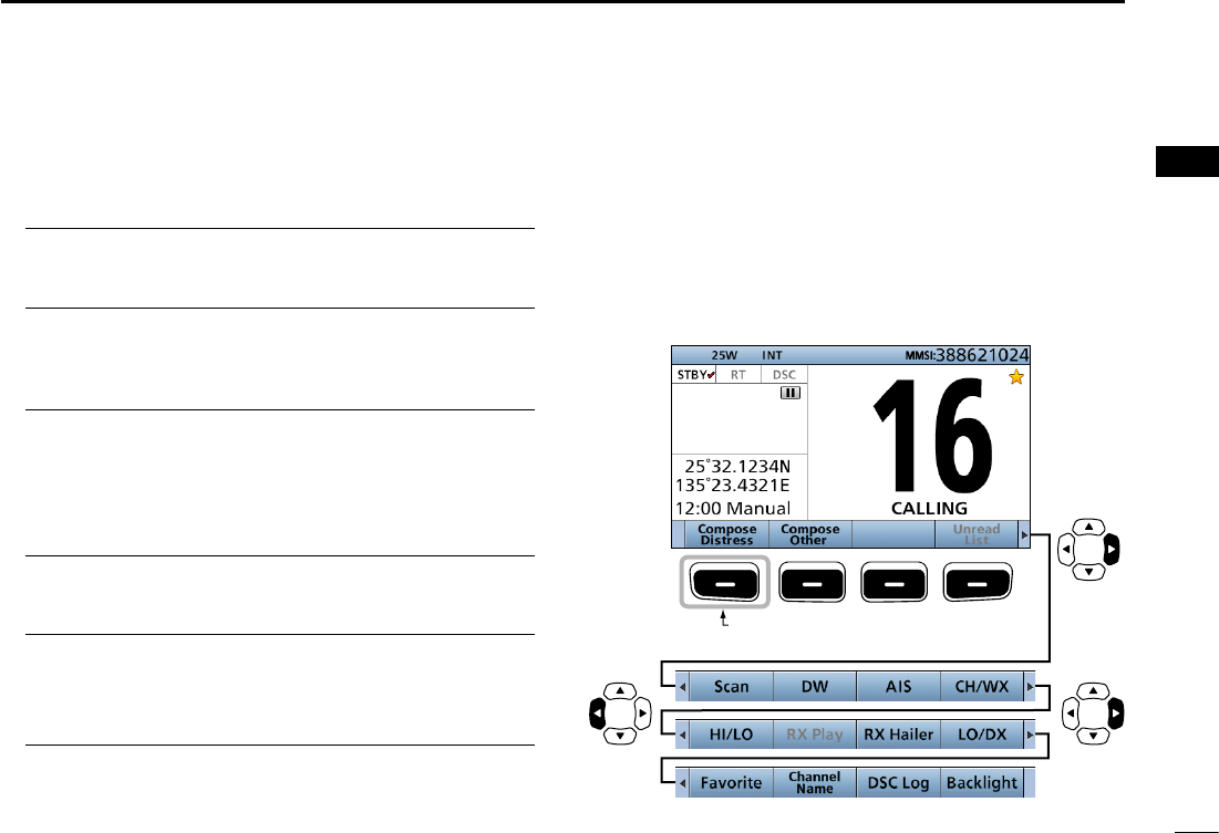
■Software Key function
The transceiver has Software Keys for various functions.
The key function is displayed above the Software Key.
DSelecting the Software Key function
When “Ω” or “≈” is displayed beside the key icon, pushing
[Ω] or [≈] scrolls the Software Key functions.
When you push [Ω] or [≈] once, 4 functions scroll together.
Push this key to display the
COMPOSE DISTRESS screen.
Push
PushPush
* The key functions may differ, depending on the transceiver version.
6
2PANEL DESCRIPTION
New2001
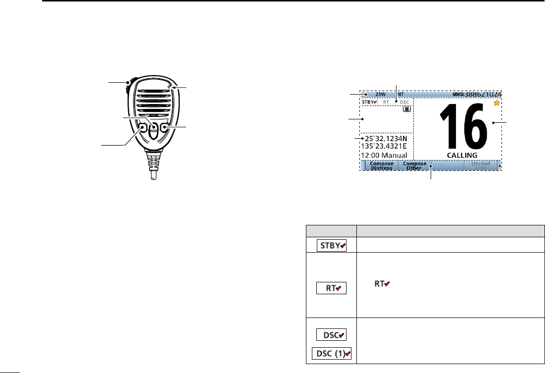
■Speaker Microphone
q PTT SWITCH [PTT] (pp. ?, ?)
Hold down to transmit, release to receive.
w UP/DOWN KEYS [▲]/[▼] (p. ?)
Push to select the Favorite channels, change scanning
direction or manually resume a scan.
L When the “FAV on MIC” item is set to “OFF,” you can select
all channels. (p. ?)
e TRANSMIT POWER KEY [H/L]
zPush to set the power level to high or low. (p. ?)
LSome channels are set to only low power.
z While holding down this key, turn ON the transceiver to
turn the Microphone Lock function ON or OFF.
(p. ?)
r CHANNEL 16/CALL CHANNEL KEY [16/C] (p. ?)
zPush to select Channel 16.
zHold down for 1 second to select the Call channel.
• The “CALL” icon is displayed.
q PTT SWITCH
[PTT]
w UP/DOWN KEYS
[Y]/[Z]
e TRANSMIT
POWER KEY
[H/L]
Microphone
r CHANNEL 16/
CALL CHANNEL KEY
[16/C]
Information
area
Software Key area (p. ?)
Channel
area
Mode/Task area
Position and
Time area
■Function display (Main screen)
Status area
DMode/Task area
The current mode is displayed in the Mode and Task area.
Indicator Description
Displayed in the Standby mode.
Displayed while in the Radio Telephone (RT)
mode. (p. ?)
L “ ” is displayed when the RT mode task is
activated.
L Returns to the Standby mode if no operation
occurs during the preset period of time. (p. ?)
Displayed after making or receiving a DSC
call.
(p. ?)
L If the transceiver is in the Multi Task mode, the
number of DSC tasks is displayed by the indicator.
7
2
PANEL DESCRIPTION
New2001
1
2
3
4
5
6
7
8
9
10
11
12
13
14
15
16
DPosition and Time area
POSITION AREA
The current position is displayed when valid GPS data is
received, or you manually enter your position.
Indicator Description
NO
POSITION
Displayed when a GPS receiver is not
connected and your position has not been
manually entered.
??
Blinks every 2 seconds instead of your
position when the GPS position is invalid.
L The last position is held for only 23.5 hours. After
that, “NO POSITION” will be displayed.
Blinks every 2 seconds instead of the position
after 4 hours have passed since you manually
entered your position.
L The manually entered position is held for only
23.5 hours. After that, “NO POSITION” will be
displayed.
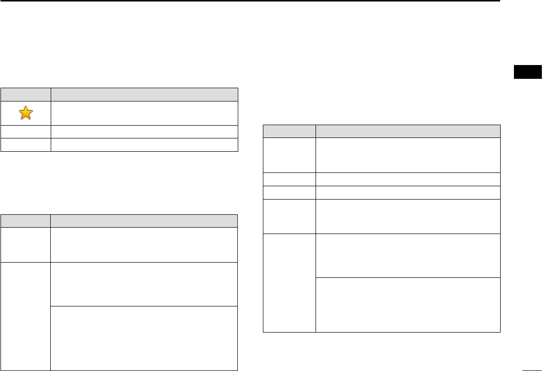
DChannel area
The selected operating channel number, channel name, and
the following indicators are displayed in the Channel area.
Indicator Description
Displayed when a Favorite channel is
selected.
CALL Displayed when the Call channel is selected.
DUP Displayed when a Duplex channel is selected.
DPosition and Time area (continued)
TIME AREA
The current time is displayed when valid GPS data is
received, or manually enter the time.
The date information is displayed when the RMC GPS
sentence formats are included in the GPS signal.
Indicator Description
NO TIME
Displayed when a GPS receiver is not
connected and the time has not been
manually entered.
Local Displayed when the offset time is set.
Manual
Displayed when the time was manually entered.
UTC
Displayed when the GGA, GLL or GNS GPS
sentence formats are included in the GPS
signal.
??
Blinks every 2 seconds instead of the time
when the GPS current time is invalid.
L After 23.5 hours has passed, “NO TIME” will be
displayed.
Blinks every 2 seconds instead of the
time after 4 hours have passed since you
manually entered the time.
L The manually entered time is held for only 23.5
hours. After that, “NO TIME” will be displayed.
New2001
8
2PANEL DESCRIPTION
New2001
New2001
■Function display (Main screen) (Continued)
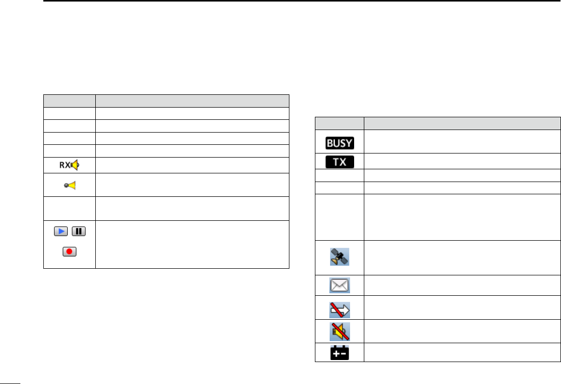
DInformation area
The 9 digit Maritime Mobile Service Identity (MMSI: DSC
self ID) code and the following indicators are displayed in
the Information area.
Indicator Description
Displayed when receiving a signal or when the
squelch is open.
Displayed while transmitting.
25W Displayed when high power is selected.
1W Displayed when low power is selected.
USA, INT,
CAN, WX
• Displayed when the USA, International, or
Canada channel group is selected.
• “WX” is displayed when the weather channel
is selected.
Displayed when the transceiver receives valid
GPS data from the GPS receiver.
Blinks when invalid GPS data is being received.
Blinks when there are unread DSC messages.
Displayed when the “CH Auto Switch” in DSC
Settings is set to an option except “Manual.”
Displayed when the “Internal Speaker” item is
OFF. (p. ?)
Displayed when the battery voltage is low.
DStatus area
The current status is displayed in the Status area.
Indicator Description
SCAN 16 Displayed during a Priority scan. (p. ?)
SCAN Displayed during a Normal scan. (p. ?)
DUAL 16 Displayed during Dualwatch. (p. ?)
TRI 16 Displayed during Tri-watch. (p. ?)
Displayed when in the RX Hailer mode. (p. ?)
Displayed when the Auto Foghorn function is
activated. (p. ?)
Displayed when the Automatic Foghorn
function is activated,
• Displayed when recorded audio is played or
stopped.
• Displayed when received audio is recorded.
9
New2001
2
3
PREPARATION 3
1
4
5
6
7
8
9
10
11
12
13
14
15
16
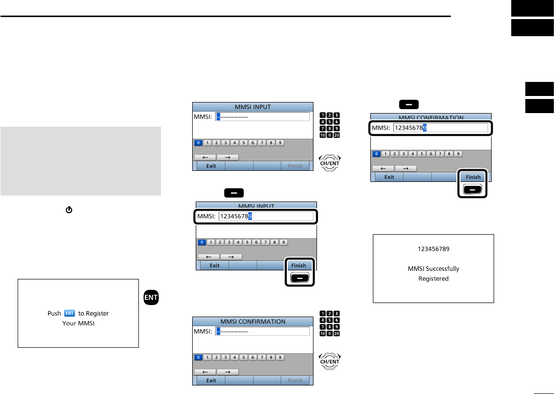
■Entering the MMSI code
First, you must enter the 9 digit MMSI
(Maritime Mobile Service Identity: DSC
self ID) code at power ON.
NOTE: You can enter this initial code
ONLY ONCE. After entry, only your
dealer or distributor can change it.
If you have already entered your
MMSI code, these procedures are not
necessary.
1. Hold down [ ] for 1 second to turn
ON the transceiver.
• Three short beeps sound.
• “Push [ENT] to Register Your MMSI” is
displayed.
2. Push [ENT] to enter the MMSI
code entry mode.
Push
• Push [CLR] to cancel the entry. In that
case, the transceiver displays “Push
[ENT] to Register Your MMSI” again.
3. Enter your 9 digit MMSI code.
4. After entering the 9th digit, push
[Finish] to set the ID.
5. Reenter your MMSI code to
confirm.
6. After entering the 9th digit, push
[Finish] to register the ID.
• When you successfully enter your
MMSI code, the following screen is
displayed.
• After that, the Main screen is
displayed. The registered MMSI code
is displayed at the top of the screen.
+
Rotate
Push
+
Rotate
Push
Push
Push
10
New2001New2001
MENU SCREEN
4
You can use the Menu screen to
set infrequently changed values or
function settings.
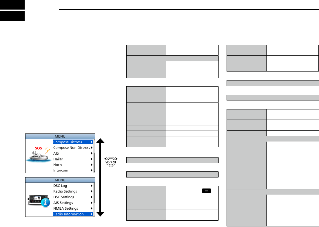
■Construction
The Menu screen is constructed in a
tree structure.
You can go to the next tree level with
[ENT], or go back a level with [CLR].
LSee page iv for details.
To select an item, rotate [CH/ENT].
Rotate
•Compose Distress (p. ??)
Nature of Distress Select a Nature of
Distress option.
Position
• Latitude Displays latitude data.
• Longitude Displays longitude data.
• UTC Displays UTC offset data.
•Compose Non-Distress (p. ??)
Message Type Select a Message Type
option.
Address
Enter a destination address.
Position*1Enter your position.
• Latitude*1Displays latitude data.
• Longitude*1Displays longitude data.
• UTC*1Displays UTC offset data.
Category Select a Category option.
Mode*1Select a Mode option.
Channel*1
Select an Intership
channel.
•AIS (p. ??)
Displays the AIS plotter.
•Hailer (p. ??)
Displays the Hailer function screen.
•Horn (p. ??)
Manual Horn Hold down [Horn] to
sound a horn.
Auto Foghorn Select the automatic
foghorn pattern.
Frequency Select the foghorn’s audio
frequency.
•Intercom*2 (p. ??)
RADIO Displays the transceiver’s
name.
SUB UNIT 1, 2, 3 Displays name of the unit
that are connected for the
Intercom function.
•GPS/GNSS Information (p. ??)
Displays the GPS or GNSS information.
•AquaQuake (p. ??)
Displays the AquaQuake function screen.
•Conguration (p. ??)
Key Beep Turn the Key Beep
function ON or OFF.
Key Assignment Select the items to the
assignable keys.
UTC Offset Set the UTC Offset.
Inactivity Timer
• Not DSC Related
Set the inactivity timer for
not DSC related calls.
• DSC Related Set the inactivity timer for
DSC related calls.
• Distress Related Set the inactivity timer for
Distress related calls.
• RT Related Set the inactivity timer
for the Radio Telephone
mode.
Speaker
• Internal The internal speaker
is ON and the external
speaker is OFF.
• External The internal speaker is
OFF and the external
speaker is ON.

11
4
MENU SCREEN
New2001
1
2
3
4
5
6
7
8
9
10
11
12
13
14
15
16
New2001
*1 These items may not be displayed, depending on the transceiver version.
*2 This item is displayed when the optional command microphone or command station is connected
to the transceiver.
*3 This item is not displayed, when valid GPS data is received.
Noise Cancel
• RX Set the reduction level of
the Noise Cancel function.
• TX Turn the Noise Cancel
function for the transmit
signal ON or OFF.
Power SW From Sub Unit
• All Units When you turn OFF the
command microphone,
the transceiver is turned
OFF at the same time.
• Own Unit The transceiver is not
turned OFF even if you
turned OFF the command
microphone.
•DSC Log (p. ??)
Received Call Log Displays the received call
log of Distress calls, and
calls other than Distress
calls.
Transmitted Call
Log
Displays the transmitted
call log.
•Radio Settings (p. ??)
Scan Type Select a Scan Type from
Normal Scan or Priority
Scan.
Scan Timer Turn the Scan Timer
function ON or OFF.
Dual/Tri-Watch Select the Dualwatch or
Tri-watch function.
Channel Group Select a channel group.
Call Channel Set the Call channel.
WX Alert*1Turn the Weather Alert
function ON or OFF.
Voice Record Select whether or not to
automatically record the
voice audio.
FAV Settings Set the Favorite channel
settings.
FAV on MIC Turn the FAV on MIC
function ON or OFF.
•DSC Settings (p. ??)
Position Input*3
Enter your position.
Individual ID Enter an Individual ID.
Group ID Enter a Group ID.
Auto ACK
Select whether or not to
automatically transmit an
Acknowledgement after
receiving each type of call.
Channel Auto
Switch
Select whether or to
automatically select the
channel that the DSC
call is received on, when
received.
DSC Data Output Select a DSC Data Output
option.
Alarm Status
• Safety Turn the Alarm Status for
Safety ON or OFF.
• Routine Turn the Alarm Status for
Routine ON or OFF.
• Warning Turn the Alarm Status for
Warning ON or OFF.
• Self-Terminate
Turn the Alarm Status for
Self-Terminate ON or OFF.
• Discrete Turn the Alarm Status for
Discrete ON or OFF.
CH 70 SQL Level Select the Channel 70
squelch level.
Self Check Test Starts the self check Test.
Procedure*1Select the Single task
mode or Multiple task
mode.
•AIS Settings (p. ??)
North Up/COG Up Select the display type
for AIS plotter.
CPA/TCPA Edit the alarm settings for
AIS receiver.
ID Blocking Enter the vessel’s or your
transponder ID to block.
•NMEA Settings (p. ??)
NMEA0183
• Port 1, Port 2 Select the data transfer
speed to receive data
from external devices.
NMEA2000*1
• GPS, AIS Select the sensors in
NMEA 2000 network
which sends GPS or AIS
data to the transceiver.
•Radio Information (p. ??)
Displays information on your transceiver.
L Serial number, software version, GPS
module version, and so on.
12
4MENU SCREEN
New2001
■Selecting a Menu item
Follow the procedures described below
to select a Menu item.
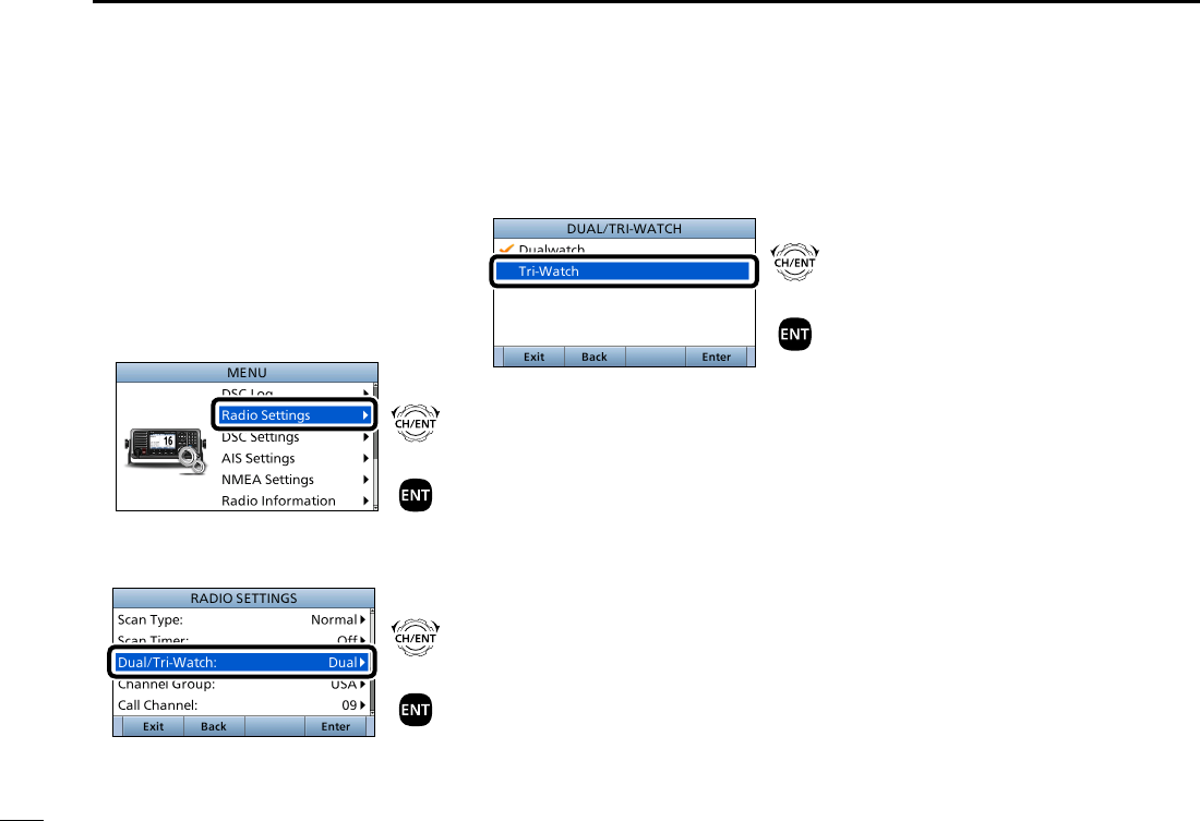
Example: Set the Tri-watch function.
1. Push [MENU] to display the MENU
screen.
2. Rotate [CH/ENT] to select
“Radio Settings,” then push [ENT].
+
Push
Rotate
3. Rotate [CH/ENT] to select
“Dual/Tri-Watch,” then push [ENT].
+
Push
Rotate
4. Rotate [CH/ENT] to select
“Tri-Watch,” and then push [ENT].
+
Push
Rotate
• Sets the Tri-watch function, and then
goes back to the RADIO SETTINGS
screen, after pushing [ENT].
5. Push [MENU] to return to the Main
screen.
13
5
BASIC OPERATION
New2001
1
2
3
4
5
6
7
8
9
10
11
12
13
14
15
16
New2001
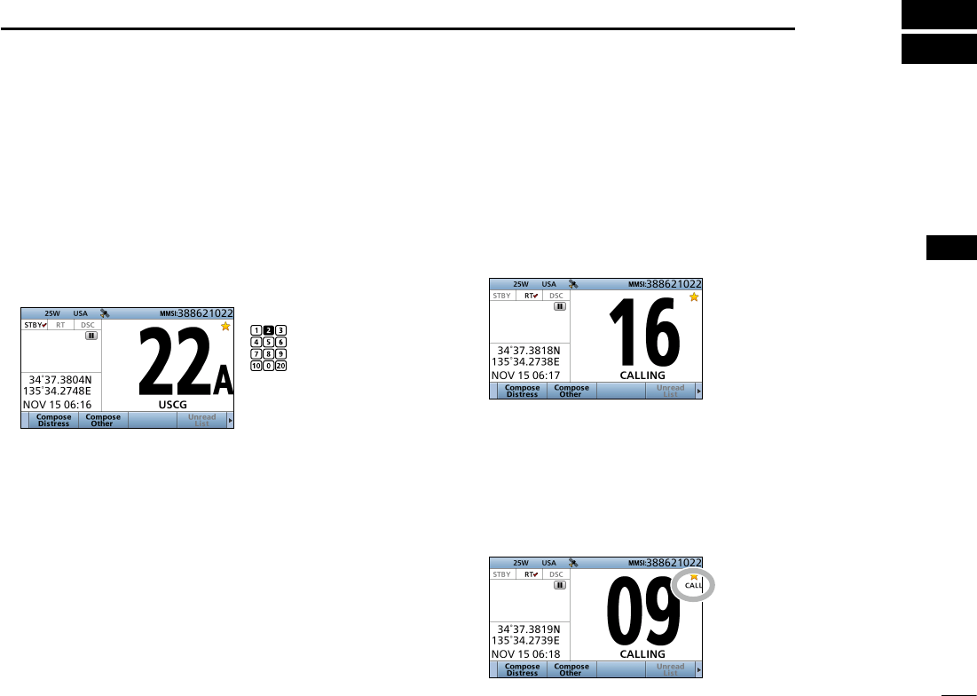
DSelecting a regular channel
zRotate [CH/ENT].
zPush [∫] or [√].
z Push the keypad to directly enter the desired channel
number.
(Example: Selecting Channel 22)
Push [2 abc] → [2 abc].
■Selecting a channel
DSelecting Call channel
You have a leisure use Call channel for quick recall.
To set your most used channel, see page ??.
The default Call channel differs, depending on the
transceiver version.
z Hold down [16/C] for 1 second.
Displayed
DSelecting Channel 16
Channel 16 is the distress and safety channel. It is used for
establishing initial contact with a station, and for emergency
communications.
While standing by, you must monitor Channel 16.
zPush [16/C].
twice
Push
14
5BASIC OPERATION
New2001
■Selecting a channel (Continued)
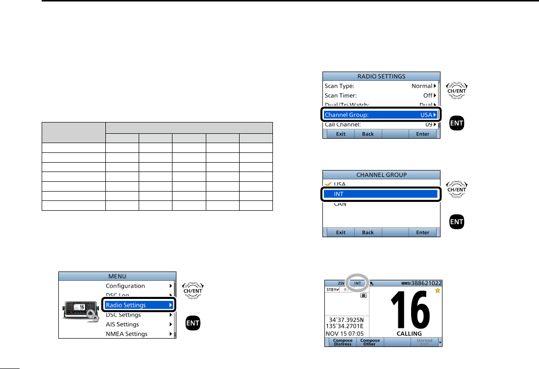
DSelecting a channel group
Channel Groups are preset into your transceiver. You can
select the Channel Group between USA, International,
Canadian, DSC, and ATIS, depending on the transceiver
version.
Version Preset Channel Group
USA INT CAN DSC ATIS
USA
UK
European
Dutch
German
Australian
Chinese
1. Push [MENU].
• The “MENU” screen is displayed.
2. Rotate [CH/ENT] to select “Radio Settings,” then push
[ENT].
+
Push
Rotate
3. Rotate [CH/ENT] to select “Channel Group,” then push
[ENT].
+
Push
Rotate
4. Rotate [CH/ENT] to select the Channel Group, then
push [ENT].
+
Push
Rotate
5. Push [MENU] to return to the Main screen.
• The selected Channel Group’s icon is displayed on the Main
screen.
15
5
BASIC OPERATION
New2001
1
2
3
4
5
6
7
8
9
10
11
12
13
14
15
16
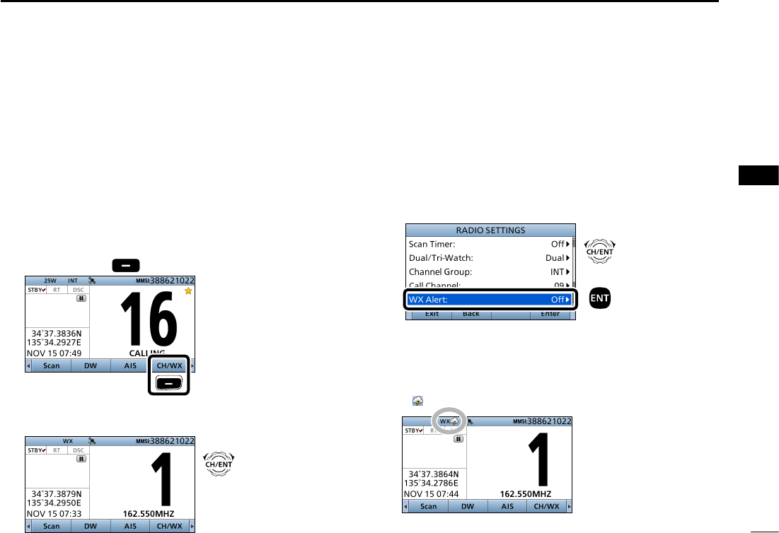
DWeather channels and Weather Alert function
For the USA and Australian versions, the transceiver has
10 preset Weather channels. You can use these channels
to monitor broadcasts from the National Oceanographic
and Atmospheric Administration (NOAA). The transceiver
automatically detects a Weather alert tone on the selected
weather channel, or while scanning.
Selecting a Weather channel
1. Push [Ω] or [≈] until “CH/WX” is displayed in the
Software Key area.
2. Push [CH/WX] .
Push
• “WX” is displayed instead of the Channel Group icon.
3. Rotate [CH/ENT] to select a Weather channel.
Rotate
Setting the Weather Alert function
L See page ?? for details on the Weather Alert function.
1. Push [MENU].
• The “MENU” screen is displayed.
2. Rotate [CH/ENT] to select “Radio Settings,” then push
[ENT].
3. Rotate [CH/ENT] to select “WX Alert,” then push [ENT].
+
Push
Rotate
• The “WX ALERT” screen is displayed.
4. Rotate [CH/ENT] to select “On with Scan” or “On,” then
push [ENT].
5. Push [MENU] to return to the Main screen.
• “ ” is displayed next to “WX” on the Main screen.
16
5BASIC OPERATION
New2001
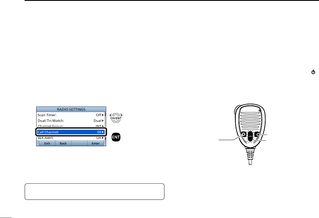
By default, a Call channel is set in each Channel Group.
You can set the Call channel with your most often-used
channel for quick recall.
1. Push [MENU].
• The “MENU” screen is displayed.
2. Rotate [CH/ENT] to select “Radio Settings,” then push
[ENT].
3. Rotate [CH/ENT] to select “Call Channel,” then push
[ENT].
+
Push
Rotate
• The “CALL CHANNEL” screen is displayed.
4. Rotate [CH/ENT] to
s
elect a channel to be set as the
Call channel, then push [ENT].
5. Push [MENU] to return to the Main screen.
■Setting the Call channel
TIP:
To conrm that your setting is correctly set, hold
down [16/C] for 1 second. (p. ??)
■ Microphone Lock function
The Microphone Lock function electrically locks [∫], [√],
[16/C] and [H/L] on the supplied microphone.
This prevents accidental channel changes or function access.
While holding down [H/L] on the microphone, hold down [ ]
for 1 second to turn ON the transceiver.
• The Microphone Lock function is turned ON or OFF.
[∫], [√]
[16/C]
[H/L]
17
5
BASIC OPERATION
New2001
1
2
3
4
5
6
7
8
9
10
11
12
13
14
15
16
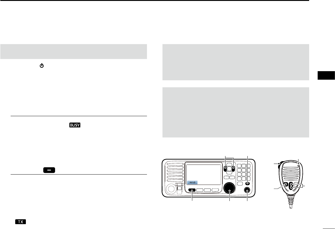
■Receiving and transmitting
1. Hold down [ ] for 1 second to turn ON the transceiver.
L If no MMSI code is entered, “Push [ENT] to Register Your
MMSI” is displayed. (p. ??)
2. Rotate [VOL/SQL] to adjust the audio level.
3. Push [VOL/SQL] once or twice to open the “SQL
Setting” window, then rotate [VOL/SQL] to adjust the
squelch level until the noise just disappears.
4. Select a channel. (p. ??)
InformationL
• When receiving a signal, “ ” is displayed.
• You can use Channel 70 only for Digital Selective Calling
(DSC) transmissions.
• When the “FAV on MIC” item is set to “OFF,” you can select all
channels using the [∫] or [√] keys on the microphone. (p. ??)
5. Push [Ω] or [≈] until “HI/LO” is displayed in the
Software Key area.
6. Push [HI/LO] to select an output power high or low.
InformationL
• “25W” is displayed when high power is selected. Choose high
power for longer distance communications.
• “1W” is displayed when low power is selected. Choose low
power for short range communications.
• Some channels are restricted to low power.
7. Hold down [PTT], and speak at your normal voice level.
• “ ” is displayed.
8. Release [PTT] to return to receive.
Microphone
4
7, 8
6
1
2, 3
6
IMPORTANT: To maximize the readability of your
transmitted signal at a receiver station, pause a second
after pushing [PTT], and then hold the microphone 5 to
10 cm from your mouth and speak at your normal voice
level.
NOTE for the Time-out Timer (TOT) function:
The TOT function inhibits continuous transmission beyond
a preset time period after the transmission starts.
10 seconds before transmission is cut off, a beep sounds
to indicate the transmission will be cut off, and “TOT” is
displayed in the channel name eld. You cannot transmit
again for 10 seconds after it is cut off.
CAUTION: DO NOT transmit without an antenna. It will
damage the transceiver.
4
5
18
5BASIC OPERATION
New2001
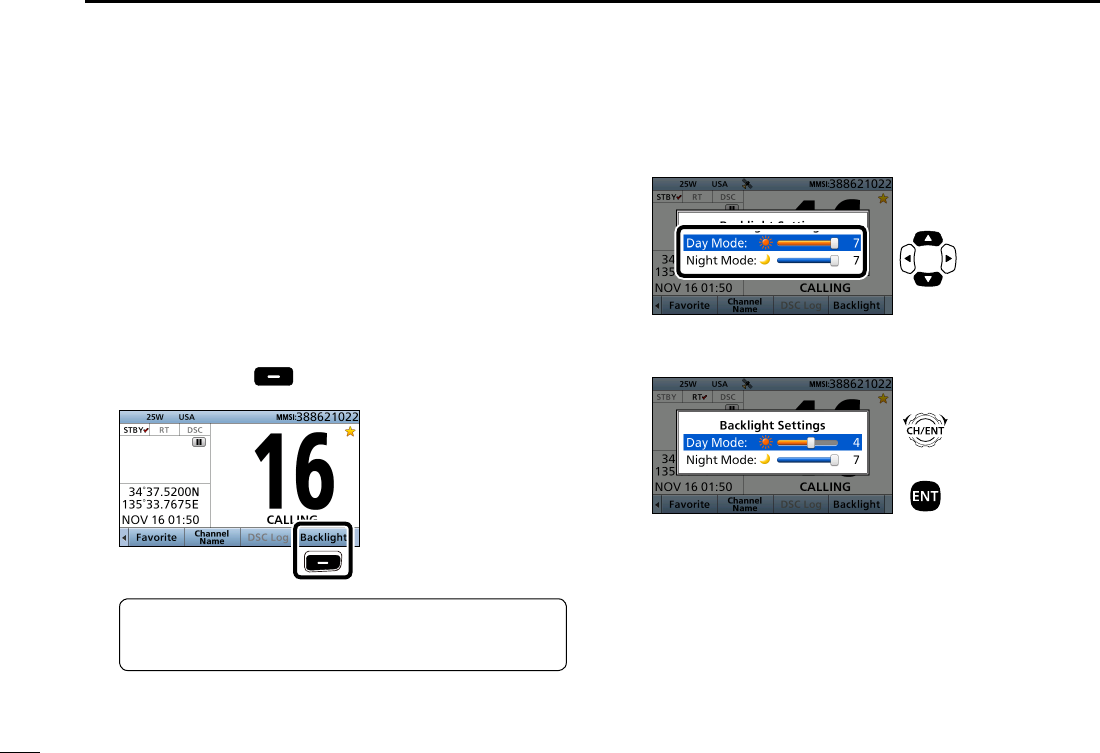
■Backlight function
The function display and keys can be backlit for better
visibility under low light conditions. And, you can set the
Backlight mode to Day mode or Night mode.
The Day mode is for the daytime operation, and the screen items
are in color.
The Night mode is for the nighttime operation, and the
screen items are in black and red.
1. Push [Ω] or [≈] until “Backlight” is displayed in the
Software Key area.
2. Push [Backlight] to open the “Backlight Settings”
window.
Push
3. Push [∫] or [√] to select “Day Mode” or “Night Mode.”
Push
4. Rotate [CH/ENT] to adjust the backlight level, then
push [ENT].
+
Push
Rotate
L The backlight level is adjustable in 7 levels and “OFF.”*
* “OFF” is selectable only for the Day mode.
TIP: In the “Backlight Setting” window, if you push no
key for about 5 seconds, the transceiver automatically
returns to the Normal operation mode.
19
5
BASIC OPERATION
New2001
1
2
3
4
5
6
7
8
9
10
11
12
13
14
15
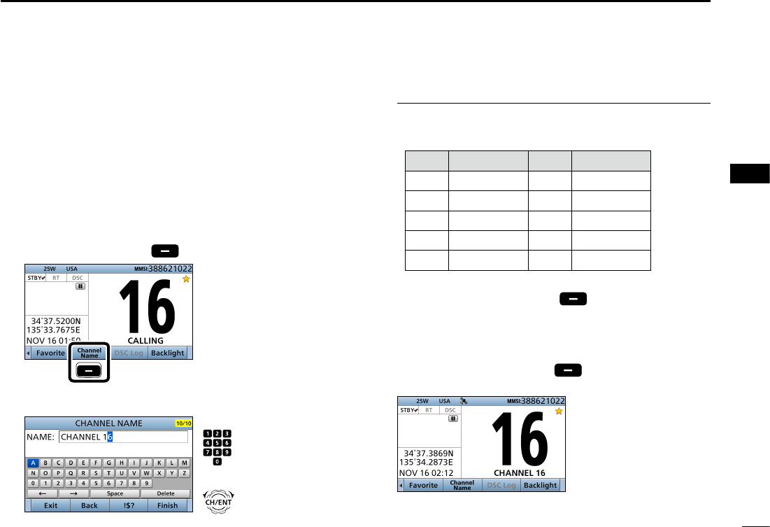
16
You can rename each channel with a unique alphanumeric
ID of up to 10 characters. This may be helpful to indicate the
frequency's use.
1.
Cancel the Dualwatch, Tri-watch or Scan function, if
activated.
2. Select a channel. (p. ??)
3. Push [Ω] or [≈] until “Channel Name” is displayed in the
Software Key area.
4. Push [Channel Name] .
Push
5. Enter a channel name.
Push
+
Rotate
■Entering a Channel name
InformationL
• You can enter the following characters by pushing the keypad
one or more times.
KEY ENTRY KEY ENTRY
[1] 1[6] 6 M N O
[2] 2 A B C [7] 7 P Q R S
[3] 3 D E F [8] 8 T U V
[4] 4 G H I [9] 9 W X Y Z
[5] 5 J K L [0] 0 . (period)
• To move the cursor, rotate [CH/ENT].
• To enter a symbol, push [“
!$?
”] . And then push [Y],
[Z], [Ω], or [≈] to select the desired character, then push
[ENT].
• To correct an entry, move the cursor to the character, and
then enter the correct character.
6. After entering, push [Finish] to return to the Main
screen.
20
5BASIC OPERATION
New2001
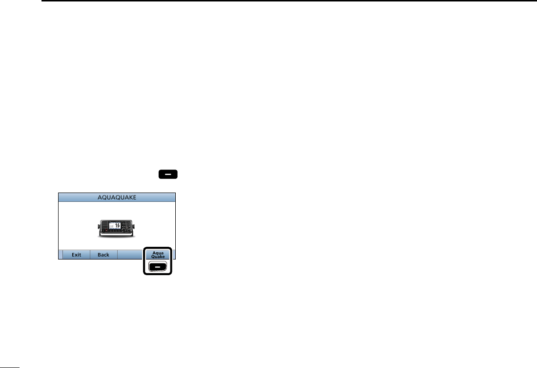
■Using the AquaQuake water draining function
Water in the speaker grill may mufe the sound coming
from the speaker. The AquaQuake Water Draining function
removes water from the speaker grill by vibrating the
speaker.
1. Push [MENU].
• The “MENU” screen is displayed.
2. Rotate [CH/ENT] to select “AquaQuake,” then push
[ENT].
3. Hold down [Aqua Quake] until all water is removed
from the speaker grill.
Hold down
• A low frequency vibration beep sounds to drain the water,
regardless of the volume level setting.
L This function is activated for a maximum of 10 seconds,
even if you continue to hold down the Software Key.
4. Push [MENU] to return to the Main screen.
20
6
SCAN OPERATION (Except for the Dutch version)
New2001
1
2
3
4
5
6
7
8
9
10
11
12
13
14
15
16
■Scan types
Except for the Dutch version, you can nd ongoing calls by
scanning the Favorite channels without rotating [CH/ENT].
The IC-M605 and IC-M605 EURO have two scan types.
• Priority scan
• Normal scan
Before you start a scan:
• Set the desired channels you want to scan as Favorite
channels. (Scans only Favorite channels.) (p. 21)
• Set the desired scan type to “Normal" or “Priority.” (p. 77)
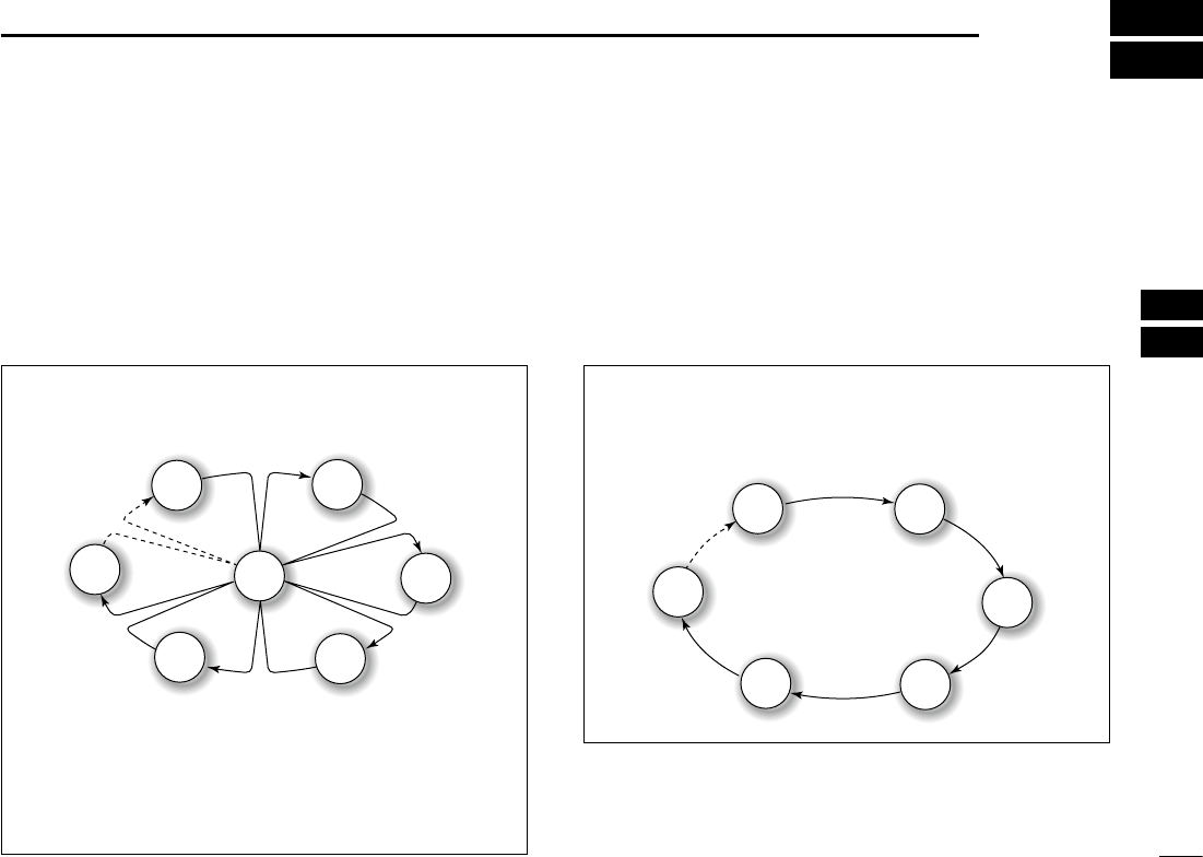
NORMAL SCAN
A Normal scan sequentially scans all Favorite channels.
However, the scan does not check Channel 16 unless it is
set as a Favorite channel.
CH 01 CH 02
CH 03
CH 04
CH 05
CH 06
PRIORITY SCAN
A Priority scan sequentially scans all Favorite channels
while monitoring Channel 16.
CH 16
CH 01 CH 02
CH 03
CH 04
CH 05
CH 06
When a signal is received:
• On Channel 16
The scan pauses until the signal on Channel 16 disappears.
• On a channel other than Channel 16:
The scan switches to Dualwatch, until the signal disappears.
21
6SCAN OPERATION (Except for the Dutch version)
New2001New2001
■Favorite channels
You can quickly recall often-used channels by setting them
as Favorite channels.
All channels are set as Favorite channels by default.
DSetting
1. Rotate [CH/ENT] to select a channel.
2. Push [Favorite] to set the channel as a Favorite
channel.
• “ ” is displayed.
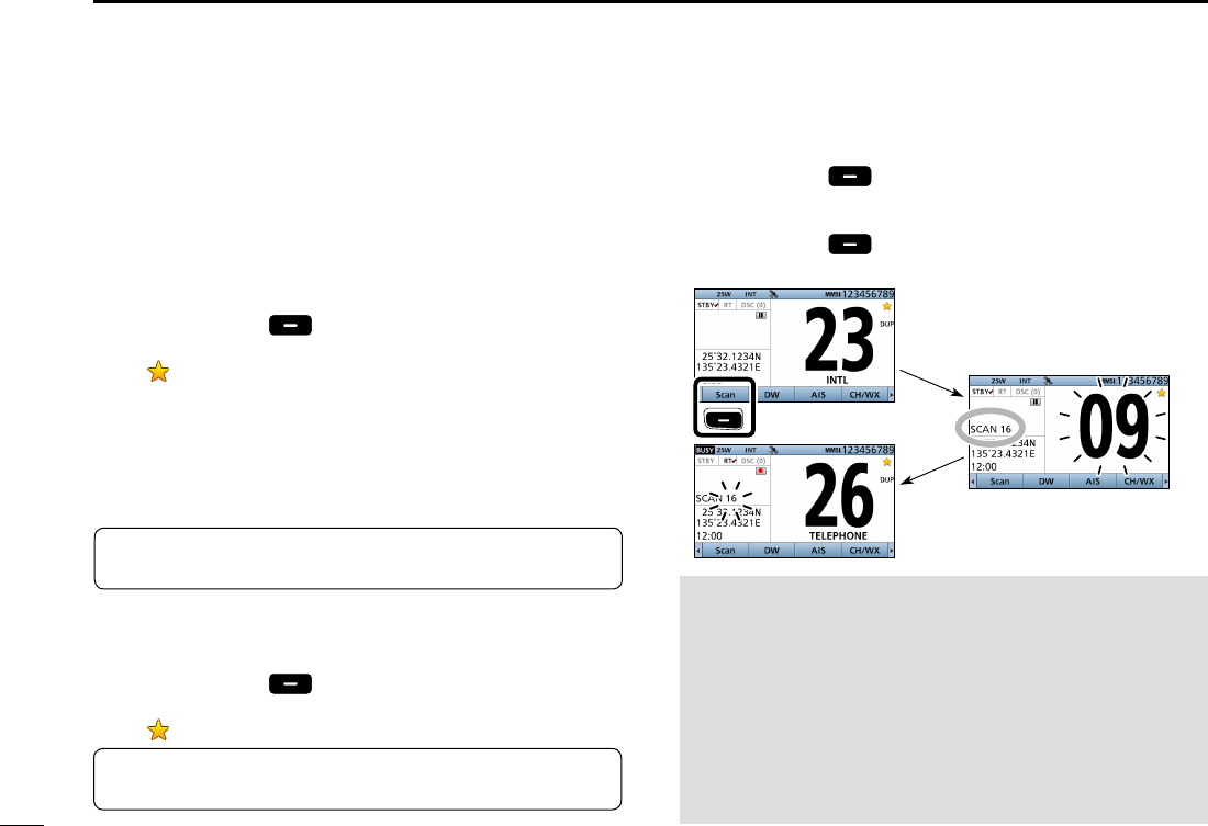
■Starting a scan
1. Push [Scan] to start a scan.
• During a Priority scan, “SCAN 16” is displayed.
• During a Normal scan, “SCAN” is displayed.
2. Push [Scan] again to cancel the scan.
• “SCAN 16” or “SCAN” disappears.
DSelecting
zPush [∫] or [√] on the microphone.
• Non-Favorite channels are skipped and not displayed.
• When the “FAV on MIC” item is set to “OFF,” you can select all
channels. (p. 78)
DClearing
1. Select a Favorite channel to clear.
2. Push [Favorite] to clear the channel as the
Favorite channel.
• “ ” disappears.
Example:
Starting a priority scan.
Scanning starts
When a signal
is received
NOTE:
• When a signal is received, the scan pauses until the signal
disappears, or resumes after pausing for 5 seconds, depending
on the “Scan Timer” setting. (p. 77)
• You can check the scanning channel, change the scan direction,
or manually resume the scan by pushing [∫] or [√] on either the
transceiver or the microphone.
• A beep tone sounds and “16” blinks when a signal is received on
Channel 16 during a Priority scan.
• In order to properly receive signals, you must adjust the squelch
to the proper level. (p. 15)
Push
TIP: You can clear all Favorite channels in the Menu screen.
(p. 78)
TIP: You can select all channels by rotating [CH/ENT] or
pushing
[∫] or [√] on the transceiver
. (p. 13)
22
7
DUALWATCH/TRI-WATCH (Except for the Dutch version)
1
2
3
4
5
6
7
8
9
10
11
12
13
14
15
16
New2001
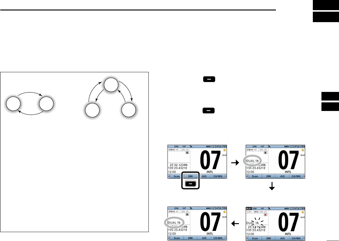
■Description
Dualwatch and Tri-watch are convenient for monitoring
Channel 16 while you are listening on another channel.
When a signal is received on
the Channel 16.
Dualwatch resumes after
the signal disappears.
When a signal is received:
• On Channel 16
Dualwatch or Tri-watch pauses on Channel 16 until the
signal disappears.
• On the Call channel
Tri-watch switches to Dualwatch until the signal on the
Call channel disappears.
■Operation
1. Select Dualwatch or Tri-watch in the Menu screen.
(p. 77)
2. Select a channel. (p. 13)
3. Push [DW] to start Dualwatch or Tri-watch.
• During Dualwatch, “DUAL 16” is displayed.
• During Tri-watch, “TRI 16” is displayed.
• A beep tone sounds and
“16” starts to blink
when a signal is
received on Channel 16.
4. Push [DW] again to cancel Dualwatch or Tri-watch.
Example: Operating Dualwatch on Channel 07.
Push
Dualwatch starts.
Dualwatch Tri-watch
CH 88
CH 16
Monitors Channel 16
while listening on
another channel
(example: CH 88).
Monitors Channel 16 and
the Call channel while
listening on another
channel (example: CH 88).
Call
channel
CH 88
CH 16
CH 9
New2001
23
New2001
DSC OPERATION
8
New2001
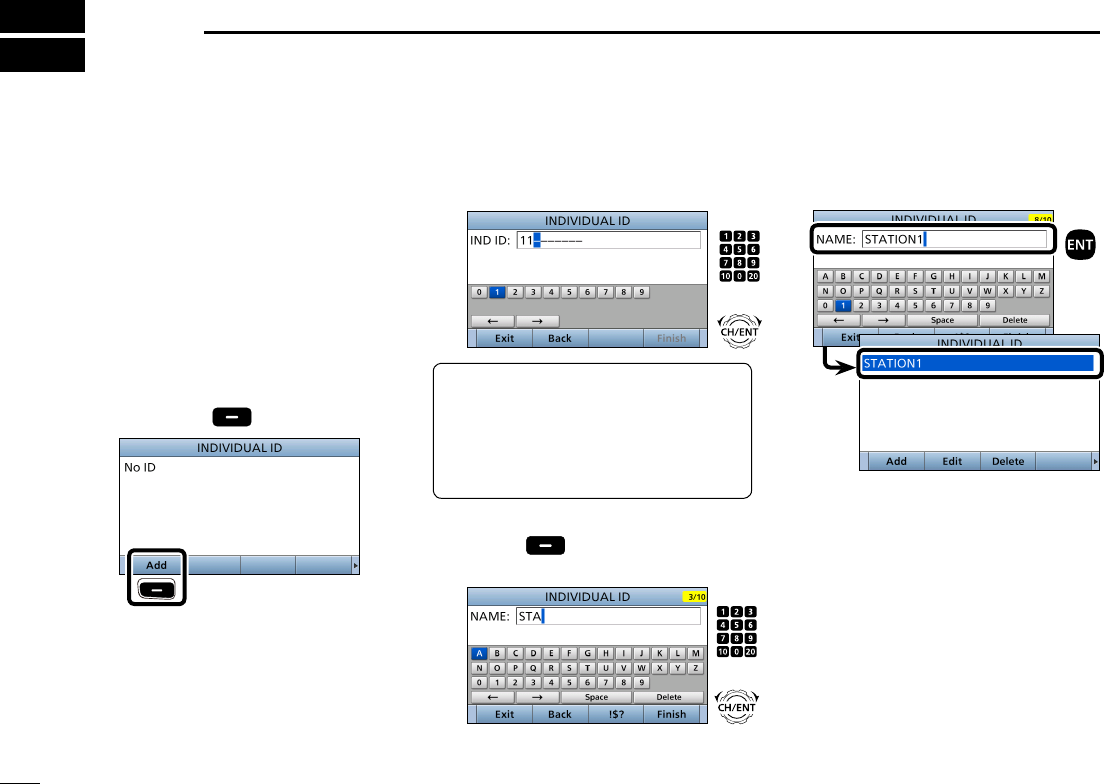
■DSC address ID
DEntering Individual ID
1. Push [MENU].
2. Select “Individual ID,” then push
[ENT].
( DSC Settings > Individual ID)
3. Push [Add] .
Push
4. Enter a 9 digit Individual ID.
TIP: You must set the rst digit for the
Individual ID to between ʻ1ʼ and ʻ9.ʼ
• The rst digit must be set to ‘0’ for a
Group ID.
• The rst two digits must be set to ‘0’ for
any Coast station ID.
5. After entering all 9 digits, push
[Finish] .
6. Enter the ID name.
LSee page XX for text entry details.
You can enter a total of 100 DSC
address IDs (Individual ID: 75, Group
ID: 25), and assign a name of up to 10
characters.
7. After entering, push [ENT].
• The entered Individual ID and name
are added to the ID list.
8. Push [MENU] to return to the Main
screen.
+
Rotate
Push
+
Rotate
Push
New2001
24
8
DSC OPERATION
New2001
1
2
3
4
5
6
7
8
9
10
11
12
13
14
15
16
New2001New2001
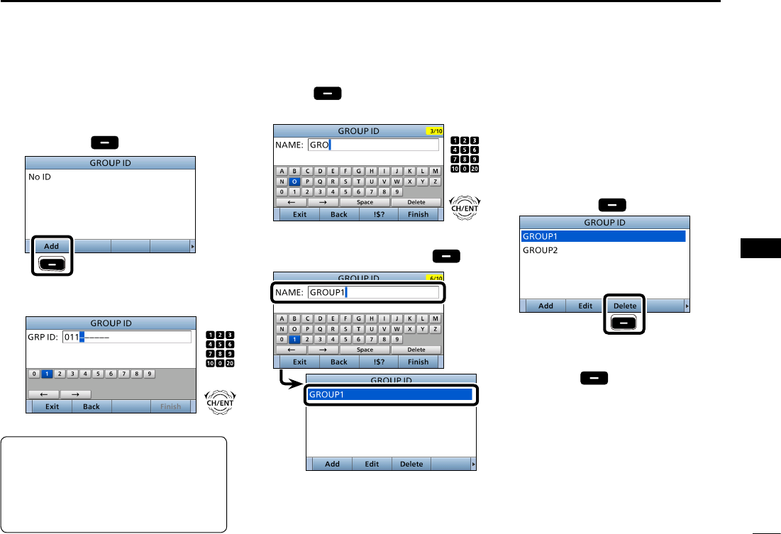
DEntering Group ID
1. Push [MENU].
2. Select “Group ID,” then push [ENT].
(DSC Settings > Group ID)
3. Push [Add] .
Push
4. Enter a 9 digit Group ID.
5. After entering all 9 digits, push
[Finish] .
6. Enter the ID name.
LSee page 18 for text entry details.
7. After entering, push [Finish] .
• The entered Group ID and name
are added to the ID list.
8. Push [MENU] to return to the Main
screen.
DDeleting an entered ID
1. Push [MENU].
2. Select “Individual ID” or “Group ID,”
then push [ENT].
( DSC Settings > Individual ID)
(DSC Settings > Group ID)
3. Rotate [CH/ENT] to select the ID
to delete.
4. Push [Delete] .
Push
• The exit conrmation dialog is
displayed.
5. Push [OK] .
• After deleting, returns to the ID list
screen.
6. Push [MENU] to return to the Main
screen.
TIP: You must set the rst digit for a
Group ID to ‘0.’
• The rst digit must be set to between ‘1’
and ‘9’ for an Individual ID.
• The rst two digits must be set to ‘0’ for
any Coast station ID.
+
Rotate
Push
+
Rotate
Push
25
8DSC OPERATION
New2001
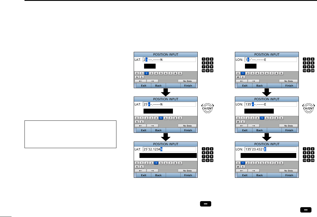
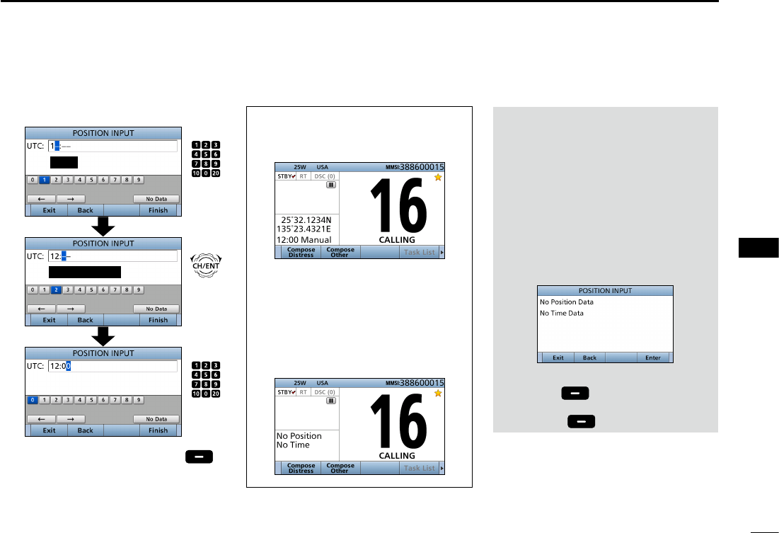
■Entering the position and time
A Distress call should include the ship’s
position and time.
When a GPS receiver compatible with
the NMEA 0183 format is connected,
position and UTC time are automatically
included.
If no GPS data is received, you should
manually enter your position (latitude
and longitude) and Universal Time
Coordinated (UTC) time.
• Manual entry is disabled when a valid
GPS data is received.
• Manually entered position and time
are valid for only 23.5 hours.
1. Push [MENU].
2. Select “Position Input,” then push
[ENT].
(DSC Settings > Position Input)
3. Enter your latitude position.
To select ʻNʼ (North latitude) or ʻSʼ (South
latitude), push any keypad key when the
cursor is on the ‘N’ or ‘S’ position.
4. After entering, push [Finish] .
5. Enter your longitude position.
L
To select W (West longitude) or E (East
longitude), push any keypad key when
the cursor is on the ‘W’ or ‘E’ position.
6. After entering, push [Finish] .
Push
Enter
Cursor moves
Set ‘W’ (West) or ‘E’ (East)
Rotate
Push
(any key)
Push
Enter
Cursor moves
Set ‘N’ (North) or ‘S’ (South)
Rotate
Push
(any key)
26
8
DSC OPERATION
New2001
1
2
3
4
5
6
7
8
9
10
11
12
13
14
15
16
NOTE:
While entering:
• To move the cursor:
Rotate [CH/ENT].
• To correct the entry:
Move the cursor to the character, then
enter the correct character.
• To clear the entry:
Push [Y], [Z], [Ω], or [≈] to select “No
Data,” then push [ENT].
When the following screen is displayed,
push [ENT].
• To return to the Main
screen
:
Push [Exit] .
• To go back to the previous screen:
Push [Back] .
When position and time data are set,
Latitude, Longitude and UTC time are
displayed.
• Latitude: 25°32.1234N
• Longitude: 135°23.4321E
• UTC time: 12:00
When no position and time data are
set,
“No Position” and “No Time” are
displayed.
7. Enter your UTC time.
8. After entering, push [Finish] .
• The DSC SETTINGS screen is displayed.
9. Push [MENU] to return to the Main
screen.
Push
Enter
Cursor moves
Rotate
Push
(any key)
27
8DSC OPERATION
New2001
■DSC Task mode (Single)
After sending or receiving a DSC call,
the transceiver enters the DSC Task
mode.
(Example: After transmitting an Individual call)
In the Task mode, you can resend the
call, or send an acknowledgement to the
caller station, and so on.
NOTE: The Task mode has a Time-
out Timer (TOT) function. When you
push no key for a preset period, the
transceiver automatically exits the
Task mode.
The count down alarm sounds 10
seconds before the TOT activates.
No count down alarm sounds before
Radio Telephone TOT activates.
The default settings of the TOT
function.
• Distress call: OFF
• Non-Distress call: 15 minutes
DSoftware key functions
When entering the Task mode, the
following functions are displayed rst.
FUNCTION
DESCRIPTION
Standby Push to delete the task and
return to the Main screen.
Resend Push to resend the call.
The following functions may be
displayed, depending on the call type.
FUNCTION
DESCRIPTION
Cancel Push to send a Cancel call.
Pause Push to pause the ‘Call repeat’
mode, or pause the countdown.
Resume Push to restart the countdown.
Finish Push to return to the Main
screen.
History Push to display the Distress call
history screen.
The following functions are displayed,
after receiving an Individual call.
FUNCTION
DESCRIPTION
ACK
(Able)
Push to send an
acknowledgment without any
changes.
ACK
(Unable)
Push to send an
acknowledgment, but you
cannot make a communication.
ACK
(New CH)
Send an acknowledgment.
You can specify the Voice
Communication channel.
28
8
DSC OPERATION
New2001
1
2
3
4
5
6
7
8
9
10
11
12
13
14
15
16
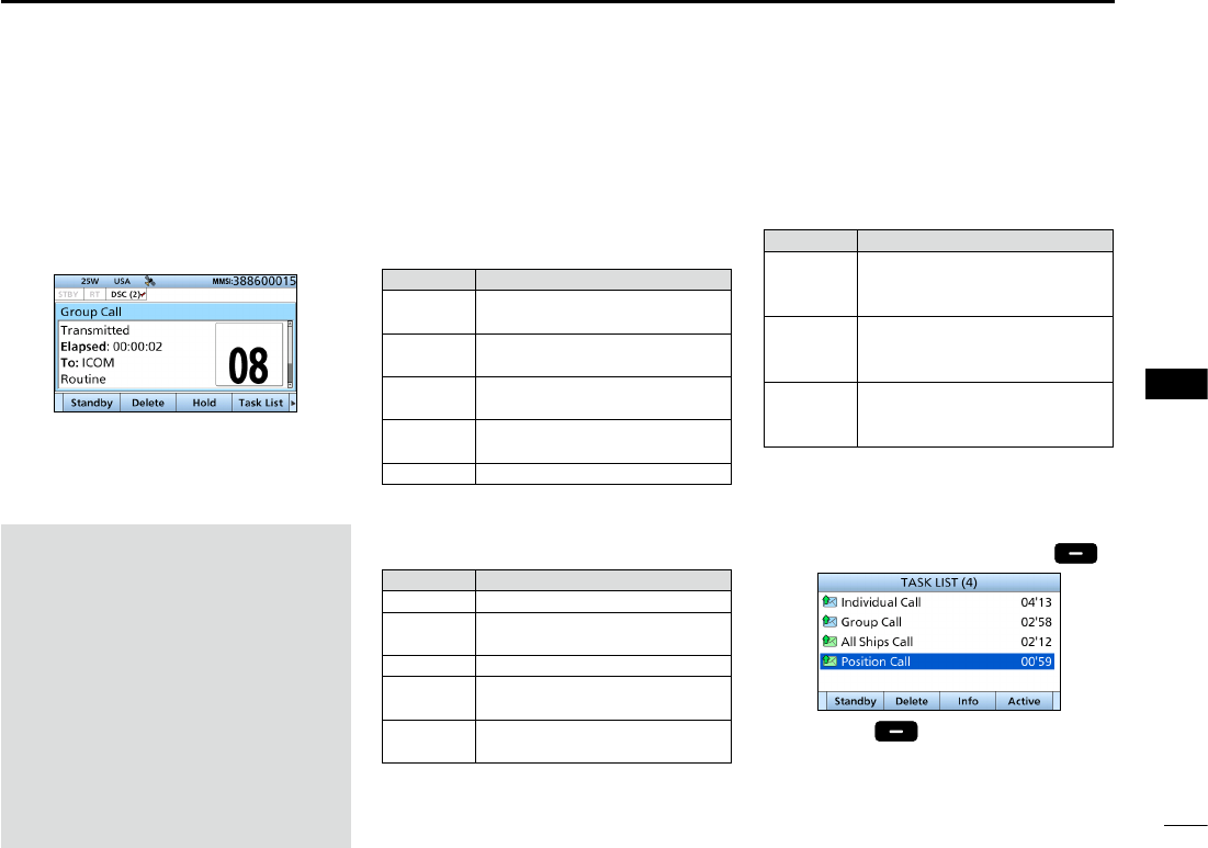
■DSC Task mode (Multiple)
If the multiple task is enabled, the
transceiver can hold up to 7 task in the
Standby mode. The number of task is
displayed in the Task area.
(Example: After receiving a Group call)
To use the Multiple task mode, select
“Multiple” in the PROCEDURE menu
(p. XX).
NOTE: The Task mode has a Time-
out Timer (TOT) function. When you
push no key for a preset period, the
transceiver automatically exits the
Task mode.
The count down alarm sounds 10
seconds before the TOT activates.
No count down alarm sounds before
Radio Telephone TOT activates.
The default settings of the TOT
function.
• Distress call: OFF
• Non-Distress call: 15 minutes
DSoftware key functions
When entering the Task mode, the
following functions are displayed rst.
FUNCTION
DESCRIPTION
Standby Push to delete the task and
return to the Main screen.
Delete Push to delete the task and
display the Task list.
Hold Push to hold the task and
display the Task list.
Task List Push to hold the task and
display the Task list.
Resend Push to resend the call.
The following functions may be
displayed, depending on the call type.
FUNCTION
DESCRIPTION
Cancel Push to send a Cancel call.
Pause Push to pause the ‘Call repeat’
mode, or pause the countdown.
Resume Push to restart the countdown.
Finish Push to return to the Main
screen.
History Push to display the Distress call
history screen.
The following functions are displayed,
after receiving an Individual call.
FUNCTION
DESCRIPTION
ACK
(Able)
Push to send an
acknowledgment without any
changes.
ACK
(Unable)
Push to send an
acknowledgment, but you
cannot make a communication.
ACK
(New CH)
Send an acknowledgment.
You can specify the Voice
Communication channel.
DTask List
When the number of task is displayed
in the standby mode, you can enter the
task mode by pushing [Task List] .
L Push [Info] to display the detail of
selected task.
(For only USA version transceiver, depending on the presetting.)
29
8DSC OPERATION
New2001
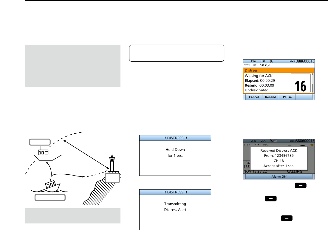
■Sending a Distress call
You should send a Distress call if, in
the opinion of the Master, the ship or
a person is in distress and requires
immediate assistance.
L Emergency channel (Channel 70) is
automatically selected to send a Distress call.
D
Simple call
1. Confirm no Distress call is being
received.
2. Lift up the key cover, then
hold down [DISTRESS] until
“Transmitting” is displayed to send
the Distress call.
• While holding down [DISTRESS],
count down beeps sound and both
the key and display backlighting blink.
•
•
•
3. After sending, the following screen
is displayed.
• Channel 16 is automatically selected.
4. When receiving the
acknowledgement:
• Alarm sounds.
• The following screen is displayed.
5. Push any [Alarm Off] .
6. Push any [Close Call RCVD
Window] .
7. Hold down [PTT] to announce your
situation.
8. Push [Standby] to return to
the Main screen.
About 20 to 30 miles
(Sea area A1)
Distress Alert
Transmission
Ship in Distress
Other ship
Coast
Station
See NOTE on page 31 for a
Distress call.
NEVER MAKE A DISTRESS CALL IF
YOUR SHIP OR A PERSON IS NOT
IN AN EMERGENCY.
A DISTRESS CALL SHOULD BE
MADE ONLY WHEN IMMEDIATE
HELP IS NEEDED.
TIP: If you want to compose a Distress
call, see ʻRegular call.ʼ (p. 30)
30
8
DSC OPERATION
New2001
1
2
3
4
5
6
7
8
9
10
11
12
13
14
15
16
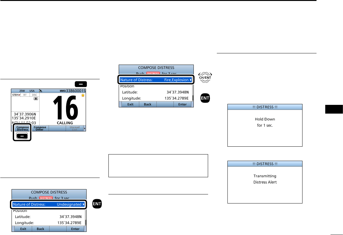
DRegular call
You can compose the Distress call.
Step 1. Display the COMPOSE DISTRESS
screen
1. Push [
Compose Distress]
.
Push
L To display the screen from the Menu
screen:
([MENU] > Compose Distress)
Step 2. Setting “Nature of Distress”
1. Push [ENT].
2. Select the option, then push [ENT].
(Example: Fire,Explosion)
Options:
Undesignated, Fire,Explosion, Flooding,
Collision, Grounding, Capsizing, Sinking,
Adrift, Abandoning Ship, Piracy, and
Man Overboard.
L The transceiver stores this setting for
30 seconds.
You can skip Step 3 below if your
position and time data are valid.
In that case, go to Step 4.
Step 3. Entering “Position”
1. Select “Position,” then push [ENT].
• The position entry screen is displayed.
2. Enter your position and time data.
LSee page 25 for entering details.
3. After entering, push [ENT].
Step 4. Sending
1. Lift up the key cover, then
hold down [DISTRESS] until
“Transmitting” is displayed to send
the Distress call.
• While holding down [DISTRESS],
count down beeps sound and both the
key and display backlighting blink.
•
•
•
Push
+
Push
Rotate
31
8DSC OPERATION
New2001
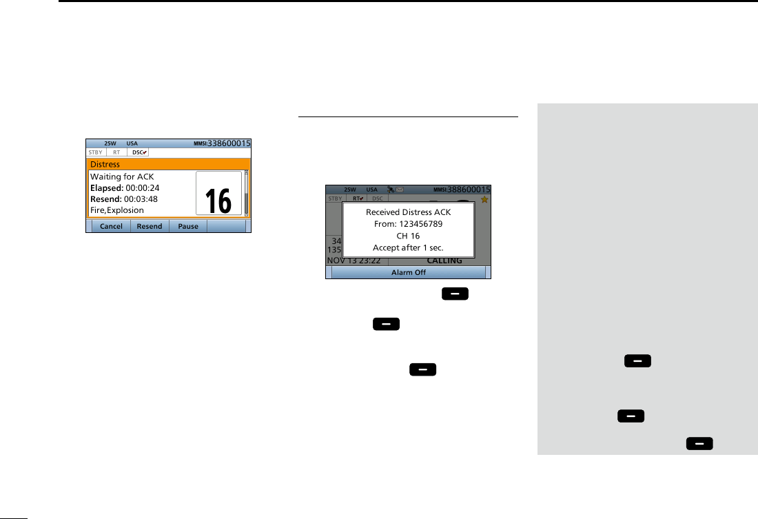
2. After sending, the following screen
is displayed.
• Channel 16 is automatically selected.
L See page 28 for details of the Task
mode’s software key functions.
NOTE:
Transmitting:
• A distress alert default contains:
- Nature of distress:
Undesignated distress (Simple call)
Selected in Step 2 (Regular call)
- Position information:
The latest GPS or manual input
position is held for 23.5 hours, or until
the power is turned OFF.
Waiting for an acknowledgement:
• The transceiver automatically sends a
Distress call every 3.5 to 4.5 minutes,
until receiving an acknowledgement (‘Call
repeat’ mode), or sending a DSC Cancel
call. (p. 33)
•
To manually send a Distress Repeat call:
Push [Resend] .
• To view the call contents:
Rotate [CH/ENT].
• To pause the ‘Call repeat’ mode:
Push [Pause] .
To resume it:
Push [Resume Countdown] .
Step 5. Replying
1. When the acknowledgement is
received:
• Alarm sounds.
• The following screen is displayed.
2. Push any [Alarm Off] .
3. Push any [Close Call RCVD
Window] .
4. Hold down [PTT] to announce your
situation.
5. Push [Standby] to return to
the Main screen.
DRegular call (Continued)
■Sending a Distress call
32
8
DSC OPERATION
New2001
1
2
3
4
5
6
7
8
9
10
11
12
13
14
15
16
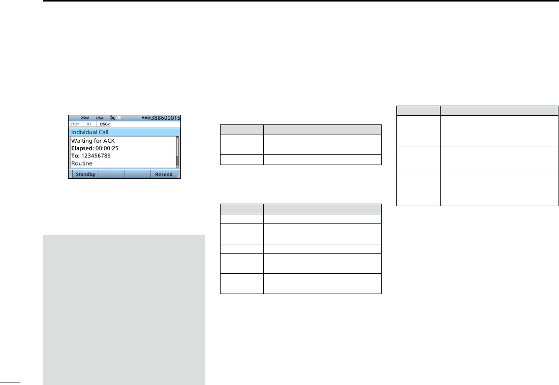
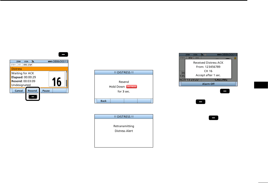
DResending a Distress call
While waiting for an acknowledgement,
you can resend the call. (Repeat call)
1. When “Waiting for ACK” is
displayed
, push [Resend]
.
Push
L See page 28 for details of the Task
mode’s software key functions.
3. When the acknowledgement is
received:
• Alarm sounds.
• The following screen is displayed.
4. Push any [Alarm Off] .
5. Push any [Close Call RCVD
Window] .
6. Hold down [PTT] to announce your
situation.
7. Push [Standby] to return to
the Main screen.
2. Lift up the key cover, then
hold down [DISTRESS] until
“Retransmitting” is displayed to
resend the call.
• While holding down [DISTRESS],
count down beeps sound and both the
key and display backlighting blink.
•
•
•
33
8DSC OPERATION
New2001
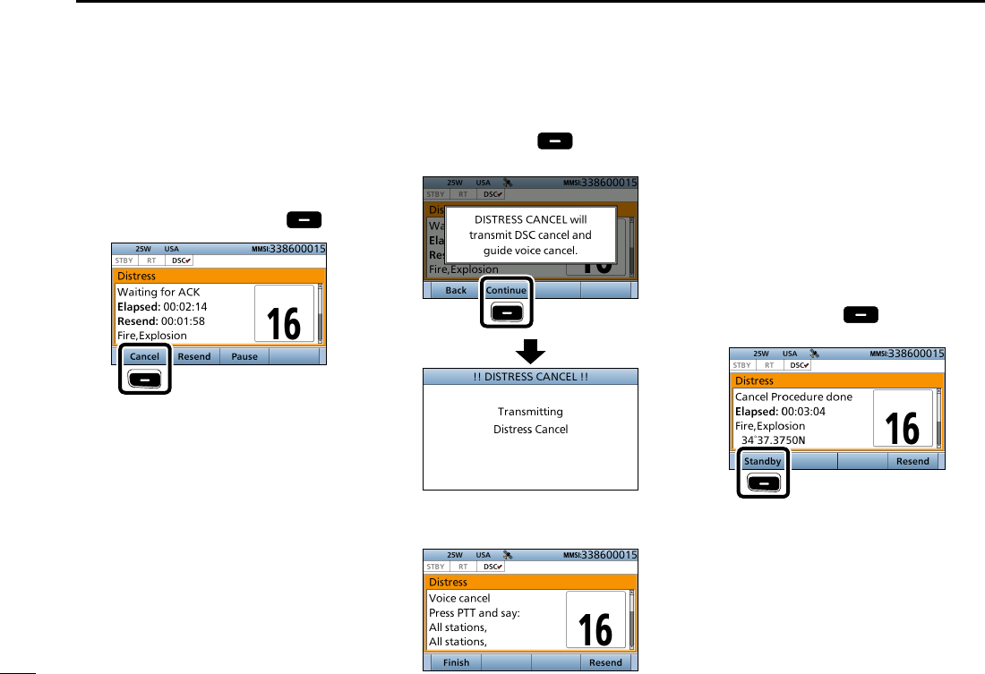
■Sending a Distress call (Continued)
While waiting for an acknowledgement,
you can send a Distress Cancel call.
1. When “Waiting for ACK” is
displayed
, push [
Cancel
]
.
Push
L See page 28 for details of the Task
mode’s Software key functions.
2. Push [Continue] to send a
Distress Cancel call.
Push
3. After sending, the following screen
is displayed.
4. Hold down [PTT] to announce your
cancel statement.
L Rotate [CH/ENT] to view the cancel
statement of the Distress Cancel call.
5. Select the action.
[Finish]: Finishes the Distress
Cancel procedures.
[Resend]: Sends a Distress Cancel
call again.
6. Push [Standby] to return to
the Main screen.
Push
DSending a Distress Cancel call
34
8
DSC OPERATION
New2001
1
2
3
4
5
6
7
8
9
10
11
12
13
14
15
16
34
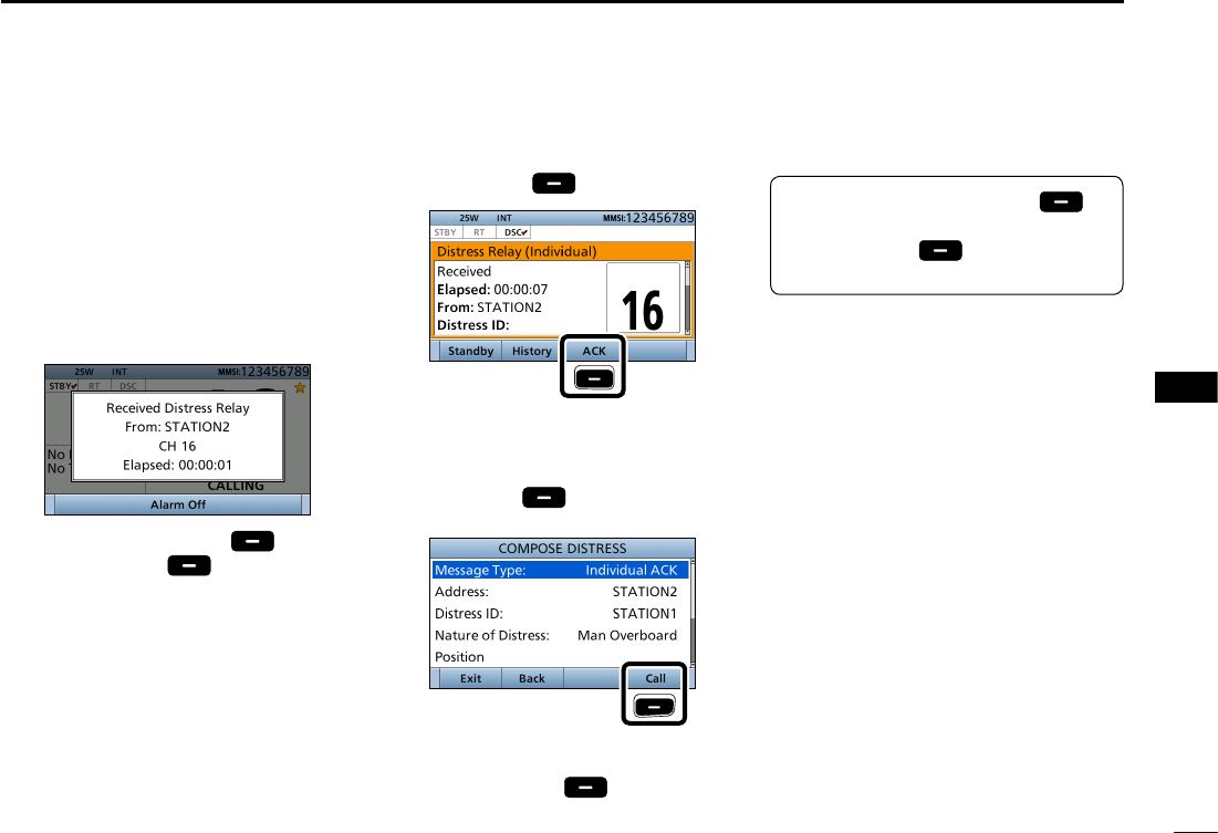
You can send the Distress Relay
acknowledgment only when the
Distress Relay call is received.
1. When a Distress Relay call is
received:
• Alarm sounds.
• The following screen is displayed.
2. Push any [Alarm Off] .
3. Push [Accept] .
• Enters the DSC Task mode.
4. Push [≈] to scroll the software key
functions.
5. Push [ACK] .
Push
• The call contents screen is displayed.
L Rotate [CH/ENT] to view the call
contents.
6. Push [Call]
to s
end the
Distress Relay acknowledgement.
Push
7. Hold down [PTT] to communicate.
8. Push [Standby] to return to
the Main screen.
D Sending a Distress Relay acknowledgement
TIP: When you push [Pause] in
step 3, the countdown will be paused.
Push [Resume] to restart the
countdown.
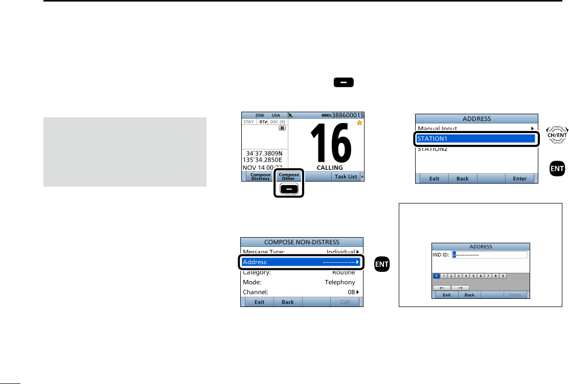
35
8DSC OPERATION
New2001
■Sending a Non-Distress call
To ensure correct operation of the DSC
function, conrm you correctly set the
Channel 70 squelch level. (p. XX)
NOTE:
• Emergency channel (Channel 70) is
automatically selected for calling.
• If Channel 70 is busy, the transceiver
stands by until the channel becomes
clear.
D Sending an Individual call
The Individual call function enables
you to transmit a DSC signal to
only a specic coast station or
ship. After transmission, wait for an
acknowledgement from the receiving
station.
You can communicate by voice after
receiving the acknowledgement ‘ACK
(Able).’
1. Push [
Compose Other]
to
display the COMPOSE NON-
DISTRESS screen.
Push
L To display the screen from the Menu
screen:
([MENU] >
Compose Non-Distress
)
2. Push [ENT].
3. Select the individual address, or
“Manual Input,” then push [ENT].
(Example: STATION1)
When you select “Manual Input” in step
3, push the keypad to manually enter
the Individual ID. (p. XX)
Push
+
Push
Rotate
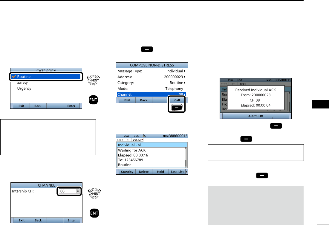
36
8
DSC OPERATION
New2001
1
2
3
4
5
6
7
8
9
10
11
12
13
14
15
16
4. Select “Category,” then push [ENT].
5. Select the option, then push [ENT].
(Example: Routine)
When you select a coast station
in step 3, the voice channel is
automatically specied by the coast
station. Therefore, skip steps 6 and 7,
and go to step 8.
6. Select “Channel,” then push [ENT].
7. Select the voice channel,
then push [ENT].
NOTE:
After receiving the acknowledgement:
• The voice channel specied in step 7 is
selected.
• A different voice channel is selected if the
station you called cannot use the channel.
8.
Push [Call]
to s
end the
Individual call.
Push
9. After sending, the following screen
is displayed.
L See page 28 for details of the Task
mode’s Software key functions.
10. When the acknowledgement is
received:
• Alarm sounds.
• The following screen is displayed.
(Example: ACK (Able))
11. Push any [Alarm Off] .
12. Push any [Close Call RCVD
Window] .
When you receive “ACK (Unable)” in
step 10, skip step 13, and go to step 14.
13. Hold down [PTT] to communicate.
14. Push [Standby] to return to
the Main screen.
+
Push
Rotate
+
Push
Rotate
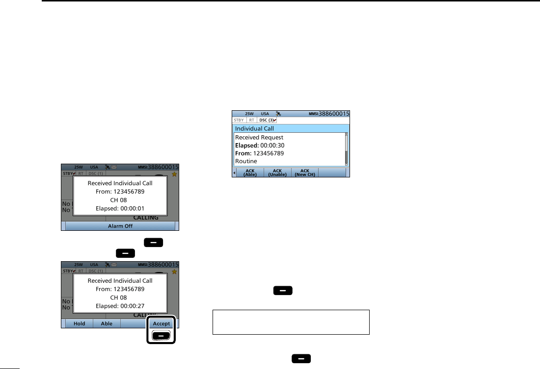
37
8DSC OPERATION
New2001
■Sending a Non-Distress call (Continued)
When receiving an Individual call, you
can send an acknowledgement (‘Able,’
‘Unable,’ or ‘New CH’) by using the on-
screen prompts.
1. When an Individual call is received:
• Alarm sounds.
• The following screen is displayed.
2. Push any [Alarm Off] .
3. Push [Accept] .
Push
• Enters the DSC Task mode.
4. Push [≈] to scroll the software key
functions.
5. Select your action.
[ACK (Able)]:
Sends an acknowledgment without any
changes.
[ACK (Unable)]:
Sends an acknowledgment, but you
cannot make a communication.
[ACK (New CH)]:
Sends an acknowledgment. You can
specify the Voice Communication
channel.
6.
Push [Call]
to s
end the
Individual acknowledgement.
When you push [ACK (Unable)] in step
5, skip step 7, and go to step 8.
7. Hold down [PTT] to communicate.
8. Push [Standby] to return to
the Main screen.
D Sending an Individual acknowledgement
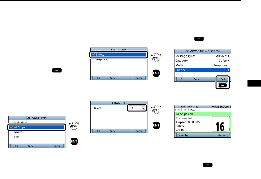
38
8
DSC OPERATION
New2001
1
2
3
4
5
6
7
8
9
10
11
12
13
14
15
16
DSending an All Ships call
All ships, that have DSC transceiver,
use Channel 70 as their ‘listening
channel.’ When you want to announce
a message to these ships within range,
use the ‘All Ships Call’ function.
1. Push [
Compose Other]
to
display the COMPOSE NON-
DISTRESS screen.
L To display the screen from the Menu
screen:
([MENU] >
Compose Non-Distress
)
2. Select “Message Type,” then push
[ENT].
3. Select “All Ships,” then push [ENT].
4. Select “Category,” then push
[ENT].
5. Select the option, then push [ENT].
(Example: Safety)
6. Select “Channel,” then push [ENT].
7. Select the voice channel,
then push [ENT].
8. Push [Call]
to s
end the All
ships call.
Push
9. After sending, the following screen
is displayed.
L See page 28 for details of the Task
mode's software key functions.
10. Hold down [PTT] to announce the
message.
11. Push [Standby] to return to
the Main screen.
+
Push
Rotate
+
Push
Rotate
+
Push
Rotate
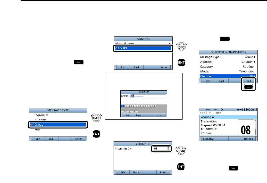
39
8DSC OPERATION
New2001
■Sending a Non-Distress call (Continued)
D Sending a Group call
The Group call function allows you to
transmit a DSC signal to only a specic
group.
1. Push [
Compose Other]
to
display the COMPOSE NON-
DISTRESS screen.
L To display the screen from the Menu
screen:
([MENU] >
Compose Non-Distress
)
2. Select “Message Type,” then push
[ENT].
3. Select “Group,” then push [ENT].
4. Select “Address,” then push [ENT].
5. Select the Group address
or “Manual Input,” then push [ENT].
(Example: GROUP1)
When you select “Manual Input” in
step 5, push the keypad to manually
enter the Group ID. (p. 24)
6. Select “Channel,” then push [ENT].
7. Select the voice channel,
then push [ENT].
8. Push [Call] to send the Group
call.
Push
9. After sending, the following screen
is displayed.
L See page 28 for details of the Task
mode’s software key functions.
10. Hold down [PTT] to announce the
message.
11. Push [Standby] to return to
the Main screen.
+
Push
Rotate
+
Push
Rotate
+
Push
Rotate
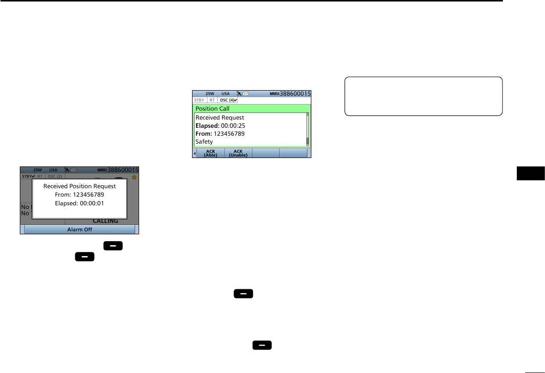
40
8
DSC OPERATION
New2001
1
2
3
4
5
6
7
8
9
10
11
12
13
14
15
16
1. When a Position Request call is
received:
• Alarm sounds.
• The following screen is displayed.
2. Push any [Alarm Off] .
3. Push [Accept] .
• Enters the DSC Task mode.
4. Push [≈] to scroll the software key
functions.
D Sending a Position Request acknowledgement
5. Select your action.
[ACK (Able)]:
Sends an acknowledgment with
position and time data.
[ACK (Unable)]:
Sends an acknowledgment with no
position and time data.
L The call contents screen is
displayed.
L
Rotate [CH/ENT] to view the call
contents.
• Change your position data, if the
displayed data is invalid. (p. 25)
6.
Push [Call]
to s
end the
acknowledgement
.
• When [ACK (Able)] is selected in step
5, your position and time data are
transmitted.
7. Push [Standby]
to r
eturn to
the Main screen.
TIP: When “Position ACK” is set to
Auto, the transceiver automatically
sends the acknowledgement. (p. 71)
When a Position Request call
is received, you can send an
acknowledgement.
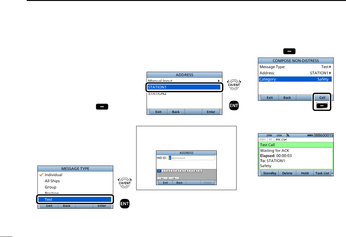
41
8DSC OPERATION
New2001
■Sending a Non-Distress call (Continued)
D Sending a Test call
Testing on the exclusive DSC distress
and safety calling channels should be
avoided as much as possible by using
other methods.
Normally the Test call would require no
further communications between the
two stations involved.
1. Push [
Compose Other]
to
display the COMPOSE NON-
DISTRESS screen.
L To display the screen from the Menu
screen:
([MENU] >
Compose Non-Distress
)
2. Select “Message Type,” then
push [ENT].
3. Select “Test.”
4. Select “Address,” then push [ENT].
5. Select the Individual address, or
“Manual Input.”
(Example: STATION1)
When you select “Manual Input” in step
5, push the keypad to manually enter
the Individual ID. (p. 23)
6. Push [Call] to send the Test call.
Push
7. After sending, the following screen
is displayed.
L See page 28 for details of the Task
mode’s Software key functions.
+
Push
Rotate
+
Push
Rotate
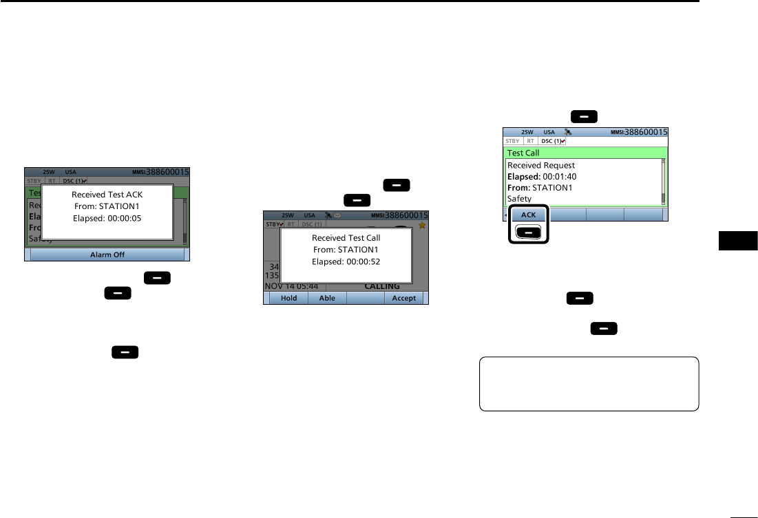
42
8
DSC OPERATION
New2001
1
2
3
4
5
6
7
8
9
10
11
12
13
14
15
16
8. When the acknowledgement is
received:
• Alarm sounds.
• The following screen is displayed.
9. Push any [Alarm Off] .
10. Push [Accept] .
• Enters the DSC Task mode.
11. Rotate [CH/ENT] to view the
received message log.
12. Push [Standby] to return to
the Main screen.
1. When a Test call is received:
• Alarm sounds.
2. Push any [Alarm Off] .
3. Push [Accept] .
• Enters the DSC Task mode.
4. Push [≈] to scroll the Software key
functions.
D Sending a Test call acknowledgement
TIP: When “Test ACK” is set to “Auto,”
the transceiver automatically sends
the acknowledgement. (p. 71)
When a Test call is received, you can
send an acknowledgement.
5. Push [ACK] .
Push
• The call contents screen is displayed.
L Rotate [CH/ENT] to view the call
contents.
6. Push [Call] to send the
acknowledgement.
7. Push [Standby] to return to
the Main screen.
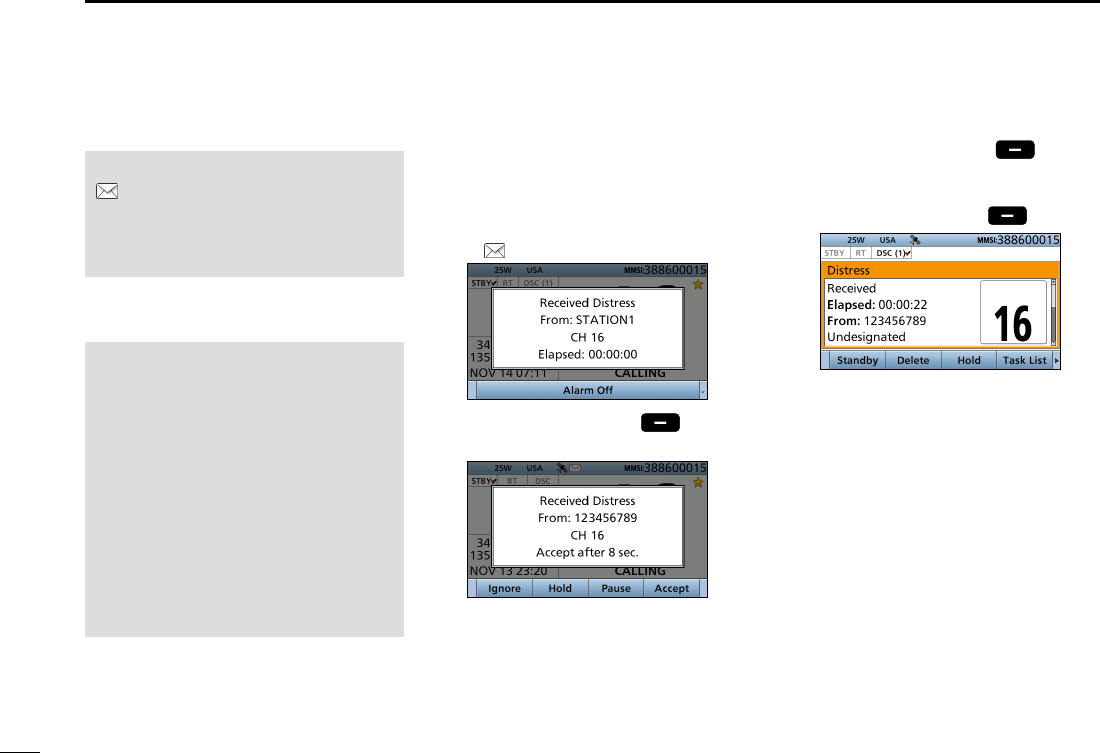
54
8DSC OPERATION
New2001
1. When a Distress call is received:
• Alarm sounds.
• The following screen is displayed
and the backlight blinks.
• “ ” blinks.
2. Push any [Alarm Off] .
3. Select your action.
[Ignore]: Ignores the Call and return
to the Main screen.
[Hold]*: Holds the RX call task,
and return to the previous
screen.
* Displayed only when “Multiple” is selected
in the PROCEDURE menu (p. XX).
■Receiving DSC calls
IMPORTANT!
Distress call reception should stop
after one sequence because the
coast station should send back an
‘acknowledgement’ to the ship.
If the distress call continues, even
after the coast station sends back an
‘acknowledgement,’ the ship in distress
may not receive the acknowledgement.
In such cases, you should send back
an ‘acknowledgement’ instead of the
coast station and contact the coast
station. (p. 34)
[Pause]: Pauses the countdown.
• To restart the countdown,
push [Resume] .
[Accept]: Enters the DSC Task mode.
To send the acknowledgement,
push [Accept] .
DSC Task mode
• Automatically selects Channel 16, and
then you should monitor it, because a
coast station may require assistance.
•
Rotate [CH/ENT] to view the call
contents.
• See page 28 for details of the Task
mode’s Software key functions.
NOTE: After receiving a DSC call
“ ” continuously blinks when the
transceiver has DSC call. or an
unread DSC message in the Received
Call Log. (p. 65)
D Receiving a Distress Call
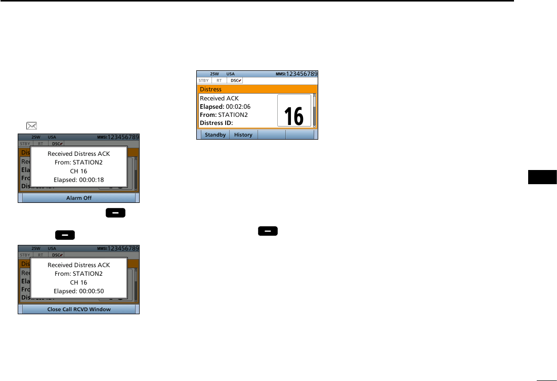
55
8
DSC OPERATION
New2001
1
2
3
4
5
6
7
8
9
10
11
12
13
14
15
16
D Receiving a Distress acknowledgement
1. When a Distress acknowledgement
sent to another ship is received:
• Alarm sounds.
• The following screen is displayed
and the backlight blinks.
• “ ” blinks.
2. Push any [Alarm Off] .
3. Push any [Close Call RCVD
Window] .
• Enters the DSC Task mode.
DSC Task mode
• Automatically selects Channel 16, and
then monitor it, because a coast station
may require assistance.
•
Rotate [CH/ENT] to view the call
contents.
• See page 28 for details of the Task
mode’s Software key functions.
4. Push [Standby] to return to
the Main screen.
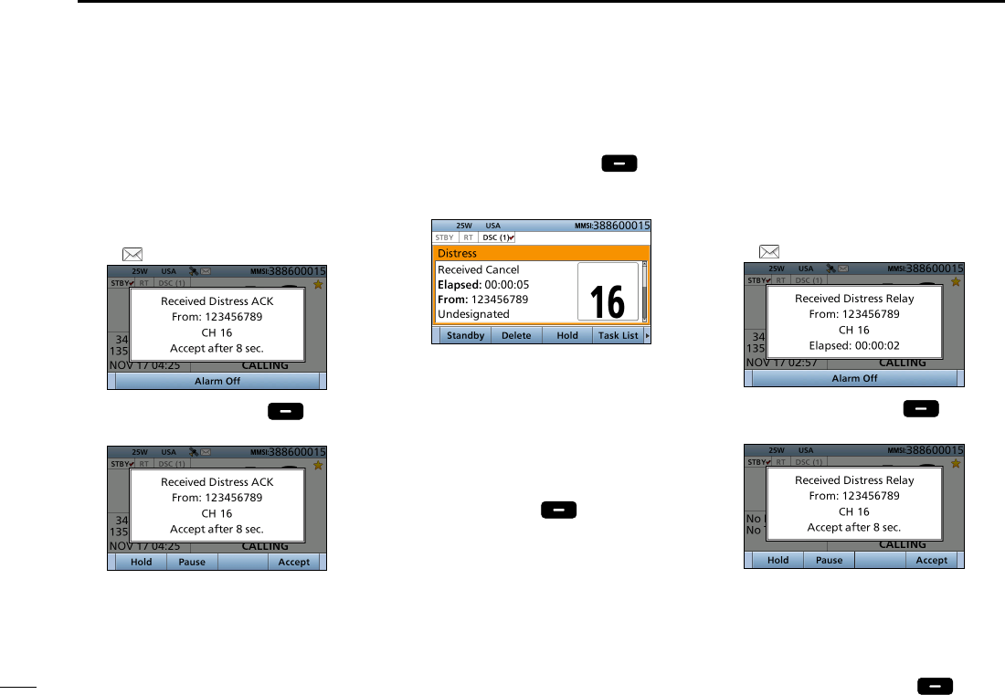
56
8DSC OPERATION
New2001
■Receiving DSC calls (Continued)
1. When a Distress Cancel call is
received:
• Alarm sounds.
• The following screen is displayed
and the backlight blinks.
• “ ” blinks.
2. Push any [Alarm Off] .
3. Select your desired action.
[Hold]: Holds the RX call task,
and return to the previous
screen.
[Pause]:
Pauses the countdown.
• To restart the countdown,
push [Resume] .
[Accept]: Enters the DSC Task
mode.
DSC Task mode
• Automatically selects Channel 16, and
then you should monitor it, because a
coast station may require assistance.
•
Rotate [CH/ENT] to view the call
contents.
• See page 28 for details of the Task
mode’s Software key functions.
4. Push [Standby] to return to
the Main screen.
D Receiving a Distress Relay call
1. When a Distress Relay call is
received:
• Alarm sounds.
• The following screen is displayed
and the backlight blinks.
• “ ” blinks.
2. Push any [Alarm Off] .
3. Select the action.
[Hold]: Holds the RX call task,
and return to the previous
screen.
[Pause]: Pauses the countdown.
• To restart the countdown,
push [Resume] .
D Receiving a Distress Cancel call
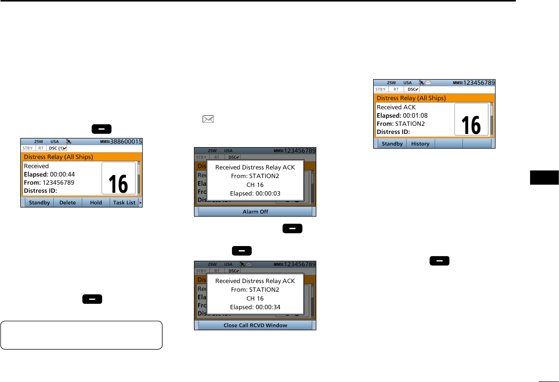
57
8
DSC OPERATION
New2001
1
2
3
4
5
6
7
8
9
10
11
12
13
14
15
16
[Accept]: Enters the DSC Task
mode.
To send the
acknowledgement,
push
[Accept] .
DSC Task mode
• Automatically selects Channel 16,
and then monitor it, because a coast
station may require assistance.
•
Rotate [CH/ENT] to view the call
contents.
• See page 28 for details of the Task
mode’s Software key functions.
4. Push [Standby] to return to
the Main screen.
1. When a Distress Relay
acknowledgement is received:
• Alarm sounds.
• “ ” blinks.
• The following screen is displayed
and the backlight blinks.
2. Push any [Alarm Off] .
3. Push any [Close Call RCVD
Window] .
• Enters the DSC Task mode.
D Receiving a Distress Relay acknowledgement
DSC Task mode
• Automatically selects Channel 16, and
then you should monitor it, because a
coast station may require assistance.
• [PTT] is activated for voice
communication via Channel 16.
• Rotate [CH/ENT] to view the call
contents.
• See page 28 for details of the Task
mode’s Software key functions.
4. Push [Standby] to return to the
Main screen.
TIP: See page 41 for details of
sending acknowledgement.
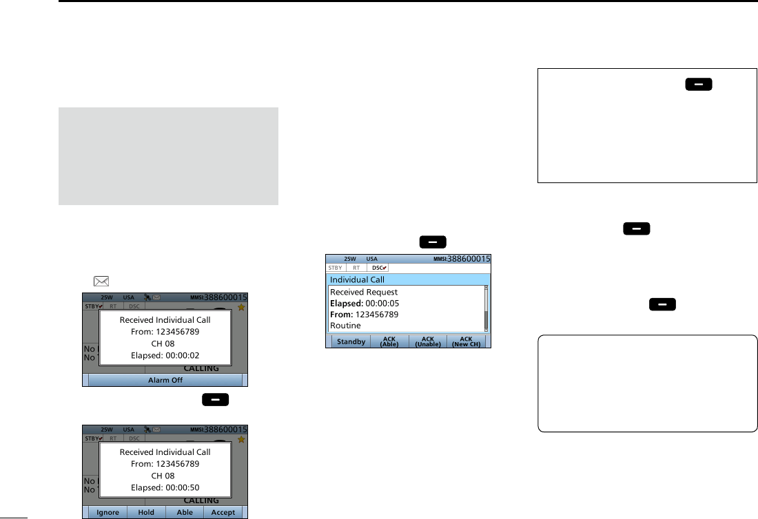
58
8DSC OPERATION
New2001
■Receiving DSC calls (Continued)
1. When an Individual call is received:
• Alarm sounds.
• The following screen is displayed
and the backlight blinks.
• “ ” blinks.
2. Push any [Alarm Off] .
3. Select your desired action.
[Ignore]: Ignores the Call and return
to the Main screen.
[Hold]: Holds the RX call task,
and return to the previous
screen.
[Able]:
Sends an acknowledgment
without any changes.
[Accept]: Enters the DSC Task
mode.
To send the
acknowledgement,
push
[Accept] .
DSC Task mode
•
Rotate [CH/ENT] to view the call
contents.
• See page 28 for details of the Task
mode’s Software key functions.
NOTE: When the “Individual
ACK” item is set to “Auto,” the
transceiver automatically sends an
acknowledgement. Both the TX and
RX calls are stored in the Transmitted
and Received Call Logs. (pp. 69, 70)
When you select [Accept] in step
3, you can send an acknowledgement
in the DSC Task mode. To send the
acknowledgement, go to step 4.
If you return to the Main screen
without sending the acknowledgement,
go to step 7.
4. Push the desired key to select an
acknowledgement option.
5.
Push [Call]
to s
end the
Individual acknowledgement.
6. Depending on the option selected
in step 5, hold down [PTT] to
communicate.
7. Push [Standby] to return to
the Main screen.
D Receiving an Individual call
TIP: When you send the
acknowledgement, select one of three
options, depending on your situation.
See page 44 for details of the
Individual acknowledgement
procedures.
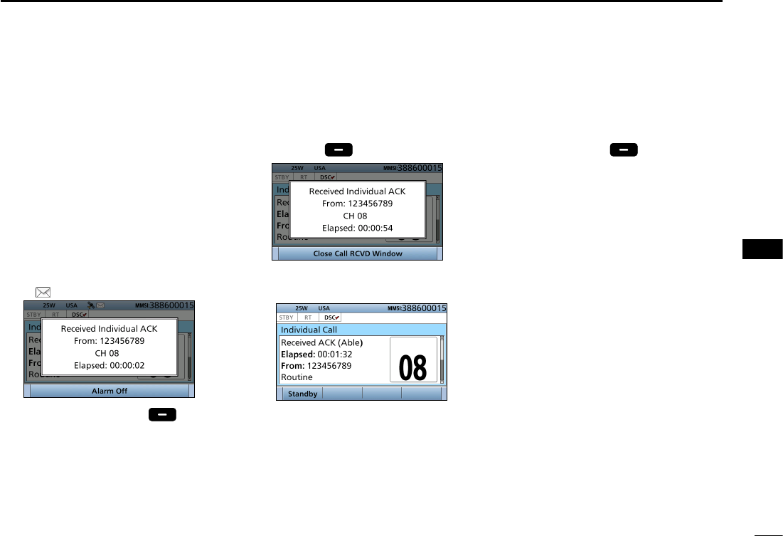
59
8
DSC OPERATION
New2001
1
2
3
4
5
6
7
8
9
10
11
12
13
14
15
16
When receiving “ACK (Able)”:
You can make voice communication
on the channel that you specied when
you sent the call.
1. When an Individual
acknowledgement “ACK (Able)” is
received:
• Alarm sounds.
• The following screen is displayed
and the backlight blinks.
• “ ” blinks.
2. Push any [Alarm Off] .
D Receiving an Individual acknowledgement
3. Push any [Close Call RCVD
Window] .
• Enters the DSC Task mode.
DSC Task mode
• Automatically selects the channel that
you specied when you sent the call
for voice communication.
•
Rotate [CH/ENT] to view the call
contents.
• See page 28 for details of the Task
mode’s Software key functions.
4. Hold down [PTT] to communicate.
5. Push [Standby] to return to
the Main screen.
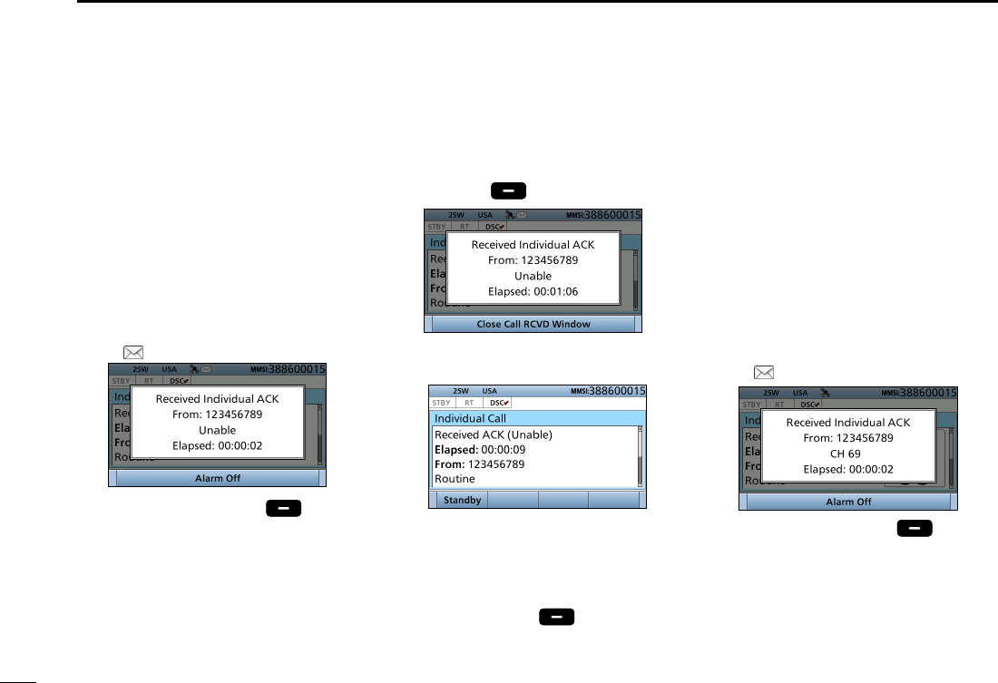
60
8DSC OPERATION
New2001
■Receiving DSC calls
D Receiving an Individual acknowledgement (Continued)
3. Push any [Close Call RCVD
Window] .
• Enters the DSC Task mode.
DSC Task mode
•
Rotate [CH/ENT] to view the call
contents.
• See page 28 for details of the Task
mode’s Software key functions.
4. Push [Standby] to return to
the Main screen.
When receiving “ACK (New CH)”:
You can make voice communication
on the channel that is proposed by the
called station.
1. When an Individual
acknowledgement “ACK (New CH)”
is received:
• Alarm sounds.
• The following screen is displayed
and the backlight blinks.
• “ ” blinks.
2. Push any [Alarm Off] .
When receiving “ACK (Unable)”:
You cannot make the voice
communication.
1. When an Individual
acknowledgement “ACK (Unable)”
is received:
• Alarm sounds.
• The following screen is displayed
and the backlight blinks.
• “ ” blinks.
2. Push any [Alarm Off] .
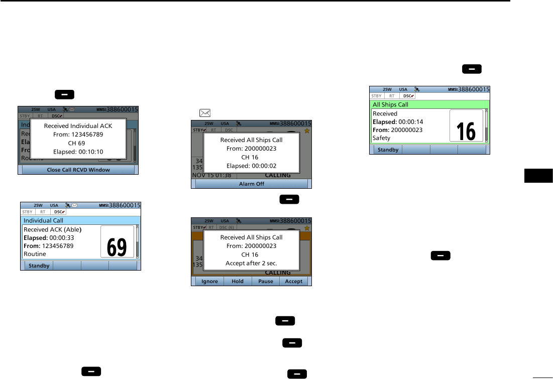
61
8
DSC OPERATION
New2001
1
2
3
4
5
6
7
8
9
10
11
12
13
14
15
16
3. Push any [Close Call RCVD
Window] .
• Enter the DSC Task mode
DSC Task mode
• Automatically selects the channel that
is proposed by the called station for
voice communication.
•
Rotate [CH/ENT] to view the call
contents.
• See page 28 for details of the Task
mode’s Software key functions.
4. Hold down [PTT] to communicate.
5. Push [Standby] to return to
the Main screen.
D Receiving an All Ships call
1. When an All Ships call is received:
• Alarm sounds.
• The following screen is displayed
and the backlight blinks.
• “ ” blinks.
2. Push any [Alarm Off] .
3. Select your desired action.
[Ignore]: Ignores the Call and return
to the Main screen.
[Hold]: Push [Hold] to return
to the Main screen.
[Pause]: Push [Pause] to
pause the countdown.
• To restart the countdown,
push [Resume] .
[Accept]: Push [Accept] to
enter the DSC Task mode.
DSC Task mode
• Monitor the channel specied by the
calling station for an announcement
from the calling station.
(Example: Channel 16)
•
Rotate [CH/ENT] to view the call
contents.
• See page 28 for details of the Task
mode’s Software key functions.
4. Push [Standby] to return to
the Main screen.
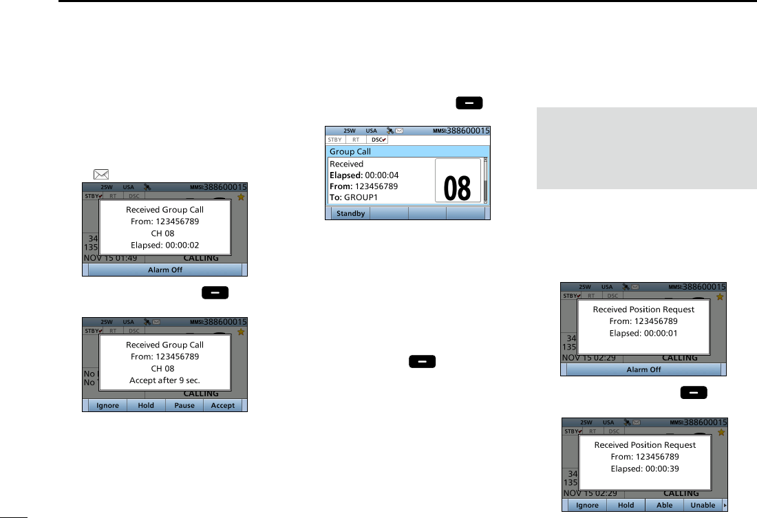
62
8DSC OPERATION
New2001
D Receiving a Group call
1. When a Group call is received:
• Alarm sounds.
• The following screen is displayed
and the backlight blinks.
• “ ” blinks.
2. Push any [Alarm Off] .
3. Select your desired action.
[Ignore]: Ignores the Call and return
to the Main screen.
[Hold]: Holds the RX call task,
and return to the previous
screen.
1. When a Position Request call is
received:
• Alarm sounds.
• The following screen is displayed
and the backlight blinks.
2. Push any [Alarm Off] .
3. Select your desired action.
■Receiving DSC calls (Continued) [Pause]: Pauses the countdown.
• To restart the countdown,
push [Resume] .
[Accept]:
Enters the DSC Task mode.
DSC Task mode
• Monitor the channel specied by the
calling station for an announcement
from the calling station.
(Example: Channel 08)
•
Rotate [CH/ENT] to view the call
contents.
• See page 28 for details of the Task
mode’s Software key functions.
4. Push [Standby] to return to
the Main screen.
D Receiving a Position
Request Call
NOTE: When “Position ACK” is set to
“Auto,” the transceiver automatically
replies to the call. Both the TX and RX
calls are stored in the Transmitted and
Received Call Logs. (Default: Manual)
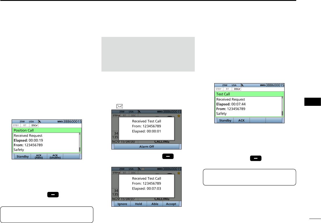
63
8
DSC OPERATION
New2001
1
2
3
4
5
6
7
8
9
10
11
12
13
14
15
16
[Ignore]:
Ignores the Call and return to the
Main screen.
[Hold]:
Holds the RX call task, and return
to the previous screen.
[ACK (Unable)]:
Sends an acknowledgment with no
position and time data.
[ACK (Able)]:
Sends an acknowledgment with
position and time data.
[Accept]:
Enters the DSC Task mode.
DSC Task mode
• Rotate [CH/ENT] to view the call
contents.
• See page 28 for details of the Task
mode’s Software key functions.
4. Push [Standby] to return to
the Main screen.
TIP: See page 48 for details of
sending an acknowledgement.
1. When a Test call is received:
• Alarm sounds.
• The following screen is displayed
and the backlight blinks.
• “ ” blinks.
2. Push any [Alarm Off] .
3. Select your desired action.
[Ignore]: Ignores the Call and return
to the Main screen.
[Hold]: Holds the RX call task,
and return to the previous
screen.
[ACK ]:
Sends an acknowledgment.
[Accept]:
Enters the DSC Task mode.
DSC Task mode
•
Rotate [CH/ENT] to view the call
contents.
• See page 28 for details of the Task
mode’s Software key functions.
4. Push [Standby] to return to
the Main screen.
NOTE: When “Test ACK” is set to
“Auto,” the transceiver automatically
replies to the call. Both the TX and RX
calls are stored in the Transmitted and
Received Call Logs. (Default: Auto)
D Receiving a Test call
TIP: See page 51 for details of
sending an acknowledgement.
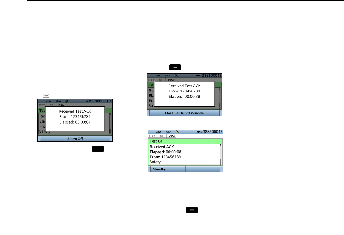
64
8DSC OPERATION
New2001
■Receiving DSC calls (Continued)
D Receiving a Test
acknowledgement
1. When a Test acknowledgement is
received:
• Alarm sounds.
• The following screen is displayed
and the backlight blinks.
• “ ” blinks.
2. Push any [Alarm Off] .
3. Push any [Close Call RCVD
Window] .
• Enters the DSC Task mode.
DSC Task mode
•
Rotate [CH/ENT] to view the call
contents.
• See page 28 for details of the Task
mode’s Software key functions.
4. Push [Standby] to return to
the Main screen.
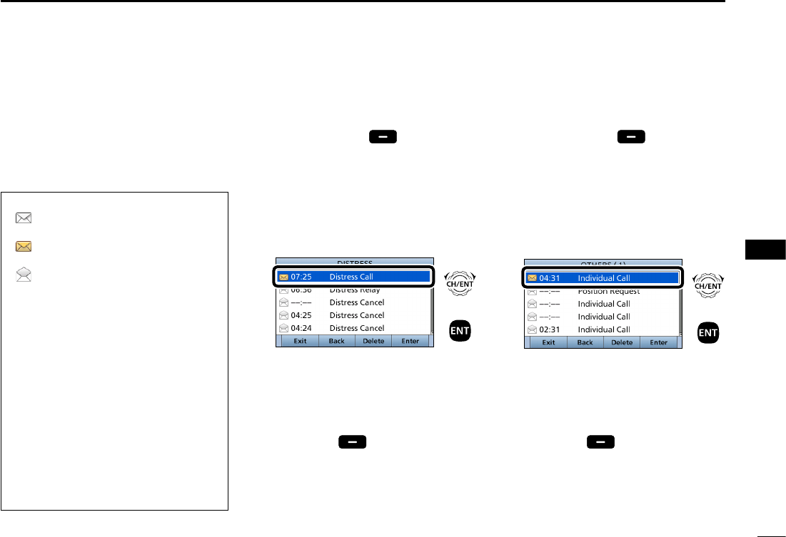
65
8
DSC OPERATION
New2001
1
2
3
4
5
6
7
8
9
10
11
12
13
14
15
16
DDistress message
1. Push [DSC Log
]
to display the
RECEIVED CALL LOG screen.
• To display the screen from the Menu
screen:
( [MENU] > DSC Log > Received Call Log)
2. Select “Distress,” then push [ENT].
3.
Select the message,
then push
[ENT].
+
Push
Rotate
4. Rotate [CH/ENT] to view the
contents.
• To view another message, push [CLR]
to return to the previous screen. And
then, select the message.
5. Push [Exit] to return to the
Main screen.
■Received Call log
DOther messages
1. Push [DSC Log
]
to display the
RCVD CALL LOG screen.
• To display the screen from the Menu
screen:
( [MENU] > DSC Log > Received Call Log)
2. Select “Others,” then push [ENT].
3.
Select the message,
then push
[ENT].
+
Push
Rotate
4. Rotate [CH/ENT] to view the
contents.
• To view another message, push [CLR]
to return to the previous screen. And
then, select the desired message.
5. Push [Exit] to return to the
Main screen.
The transceiver automatically stores up
to 50 distress messages and 50 other
messages, and they can be used as a
supplement to your logbook.
• When there is an unread DSC message,
“ ” blinks on the information area of the
LCD.
• “ ” is displayed when there are unread
DSC messages.
• “ ” is displayed when there are no
unread DSC messages.
• No icon is displayed when there are no
DSC messages.
•
Distress messages are stored in “Distress.”
Software key functions in the
RECEIVED CALL LOG screen:
[Exit]: Push to return to the Main screen.
[Back]: Push to return to the previous
screen.
[Delete]: Push to delete the selected
message.
[Enter]: Push to go to the next screen.
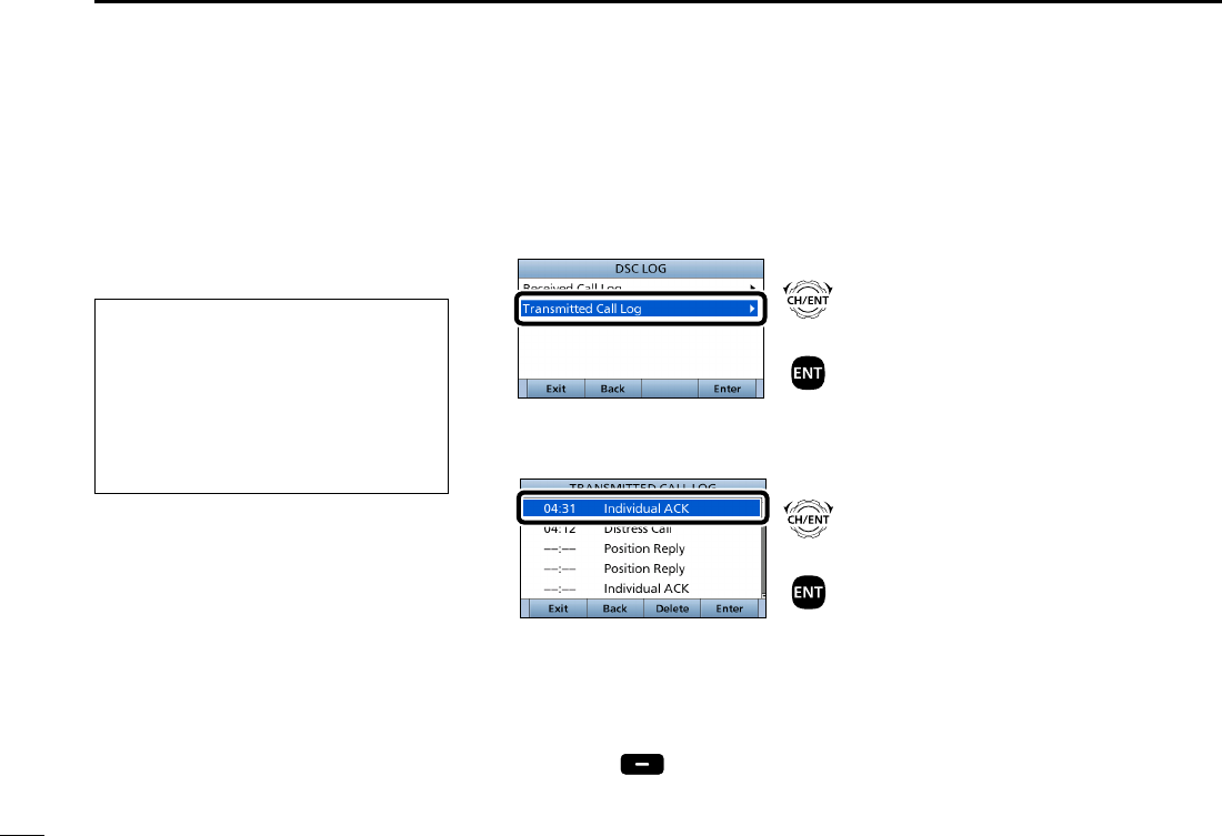
66
8DSC OPERATION
New2001
■Transmitted Call log
The transceiver automatically stores
up to 50 transmitted calls, and the logs
can be used as a supplement to your
logbook.
1. Push [MENU].
2. Select “Transmitted Call Log.”
( DSC Log > Transmitted Call Log)
+
Push
Rotate
3.
Select the desired message,
then
push [ENT].
+
Push
Rotate
4. Rotate [CH/ENT] to view the
contents.
• To view another message, push [CLR]
to return to the previous screen. And
then, select the desired message.
5. Push [Exit] to return to the
Main screen.
Software key functions in the
TRANSMITTED CALL LOG screen:
[Exit]: Push to return to the Main screen.
[Back]: Push to return to the previous
screen.
[Delete]: Push to delete the selected
message.
[Enter]: Push to go to the next screen.
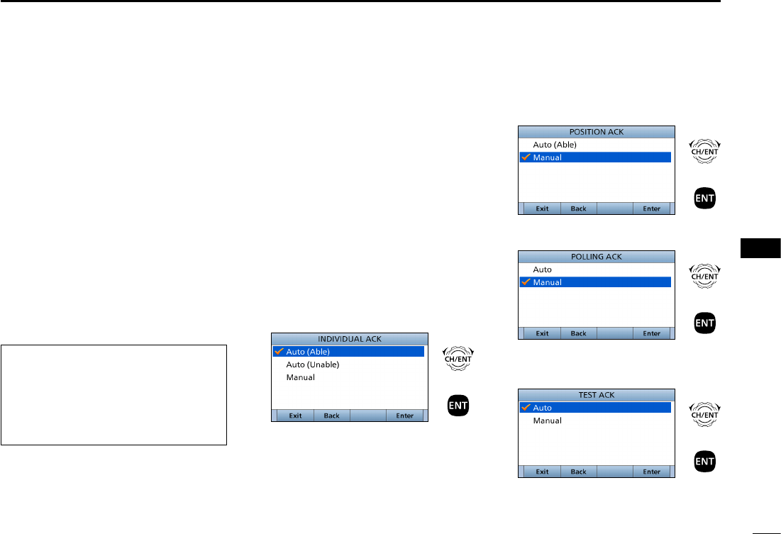
67
8
DSC OPERATION
New2001
1
2
3
4
5
6
7
8
9
10
11
12
13
14
15
16
D Automatic
Acknowledgement
You can set the Automatic
Acknowledgment function to
acknowledge DSC calls.
When you receive an Individual
call, Position Request call, Polling
Request call or Test call, the
transceiver automatically sends each
acknowledgement, if “Auto” is set.
■DSC Settings
DPosition Input (See page XX)
DIndividual ID (See page XX)
DGroup ID (See page XX)
When you set the “Individual
ACK” item to “Auto (Unable),” and
receive the Individual call, the
transceiver automatically sends the
acknowledgment, including “ACK
(Unable)” (No Reason Given).
1. Push [MENU].
2. Select “Auto ACK.”
( DSC Settings > Auto ACK)
3. Select the item.
( DSC Settings > Auto ACK >
Individual ACK)
( DSC Settings > Auto ACK >
Position ACK)
( DSC Settings > Auto ACK >
Polling ACK)
( DSC Settings > Auto ACK >
Test ACK)
4.
Select the option
, then push [ENT].
Individual ACK
+
Push
Rotate
(Default: Auto (Able))
Position ACK
+
Push
Rotate
(Default: Manual)
Polling ACK
+
Push
Rotate
(Default: Manual)
Test ACK
+
Push
Rotate
(Default: Auto)
5. Push [MENU] to return to the Main
screen.
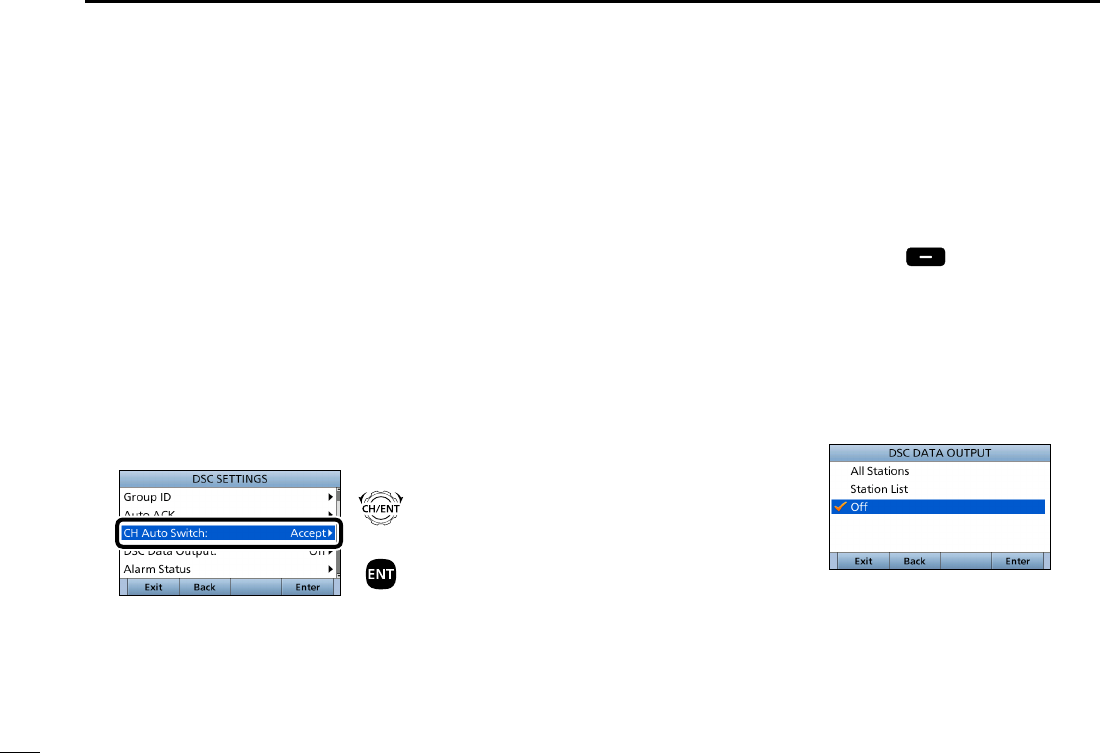
68
8DSC OPERATION
New2001
DChannel Auto Switch
By regulation, after receiving a DSC
call, the transceiver changes the
operating channel to the channel
assigned by the received DSC call.
However, when this setting is set
to “OFF,” the function enables the
transceiver to remain on the operating
channel, even after receiving a Distress
call.
1. Push [MENU].
2. Select “CH Auto Switch:,”
then
push [ENT].
( DSC Settings > CH Auto Switch:)
+
Push
Rotate
3.
Select the option
, then push [ENT].
■DSC Settings (Continued)
Accept after 10 sec.
After receiving a DSC call, the
transceiver remains on the current
operating channel for 10 seconds.
After that, the transceiver automatically
switches to the channel that assigned
by the received DSC call.
Ignore after 10 sec.*1
After receiving a DSC call, the
transceiver remains on the current
operating channel for 10 seconds.
After that, the transceiver automatically
switches to the channel that assigned
by the received DSC call.
Hold after 10 sec.*2
After receiving a DSC call, the
transceiver remains on the current
operating channel for 10 seconds.
After that, the transceiver automatically
holds the received DSC call.
Manual
The user need to select whether or not
to accept the received DSC call.
*1
Displayed only when DSC procedure
is set to “Sigle” in the Procedure menu
(p. XX)
*2
Displayed only when DSC procedure
is set to “Multiple” in the Procedure
menu (p. XX)
4. Push [Exit] to return to the
Main screen.
DDSC data output
When receiving a DSC call, this
function makes the transceiver send the
DSC data from its NMEA Output port to
an external device.
All Stations: Outputs the call from any
vessel from the NMEA
Output port.
Station List: Outputs the call from
any vessels listed on the
Individual ID screen.
OFF: Does not output any call
to an external device
(Default).
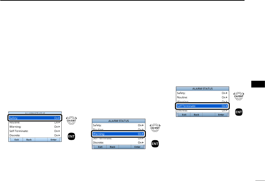
69
8
DSC OPERATION
New2001
1
2
3
4
5
6
7
8
9
10
11
12
13
14
15
16
D Setting the Alarm Status
• Safety
• Routine
Select whether or not to sound an alarm
when receiving the Safety or Routine
DSC call.
1. Push [MENU].
2. Select the item, then push [ENT].
( DSC Settings > Alarm Status >
Safety)
( DSC Settings > Alarm Status >
Routine)
(Example: Safety)
+
Push
Rotate
3.
Select the option
, then push [ENT].
• On: Alarm sounds. (Default)
• Off: Alarm does not sound.
4. Push [MENU] to return to the Main
screen.
• Warning
Select whether or not to sound an alarm:
• When no MMSI code is entered.
• When the position data has not been
updated for 10 minutes.
• When the position data has not been
manually updated for 4 hours.
• After the invalid GPS position data or
manually entered position data has not
been updated for 23.5 hours.
1. Push [MENU].
2. Select “Warning,”
then push [ENT].
( DSC Settings > Alarm Status >
Warning)
+
Push
Rotate
3.
Select the desired option,
then push
[ENT].
• On: Alarm sounds. (Default)
• Off: Alarm does not sound.
4. Push [MENU] to return to the Main
screen.
• Self-Terminate
Select whether or not to sound an alarm
when receiving the same Distress call.
1. Push [MENU].
2. Select “Self-Terminate,”
then push
[ENT].
( DSC Settings > Alarm Status >
Self-Terminate)
+
Push
Rotate
3.
Select the desired option
, then push
[ENT].
• On: Alarm sounds. (Default)
• Off: Alarm does not sound.
4. Push [MENU] to return to the Main
screen.
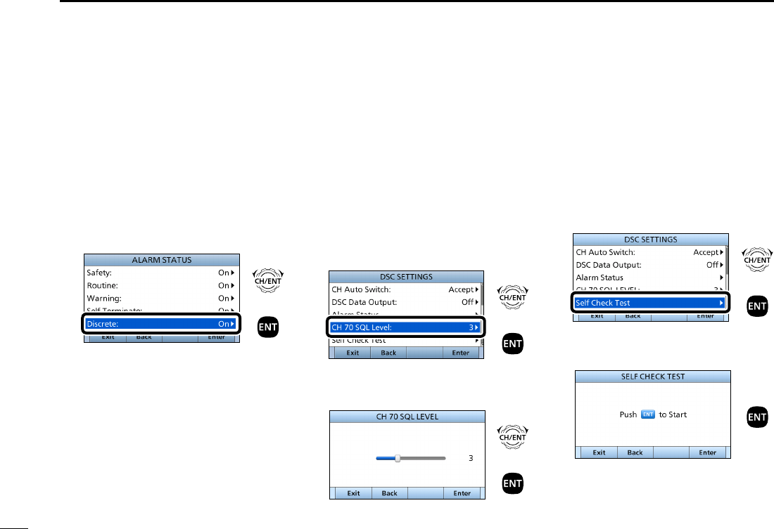
70
8DSC OPERATION
New2001
■DSC Settings (Continued)
• Discrete
Select whether or not to sound an alarm
when receiving a lower priority DSC call
while receiving a higher priority call.
1. Push [MENU].
2. Select “Discrete,”
then push [ENT].
( DSC Settings > Alarm Status >
Discrete)
+
Push
Rotate
3.
Select the desired option
, then push
[ENT].
• On: Alarm sounds. (Default)
• Off: Alarm does not sound.
4. Push [MENU] to return to the Main
screen.
D Setting the Channel 70
Squelch level
Set the squelch level on Channel 70.
The transceiver has 11 squelch levels
between 1 (loose squelch), 10 (tight
squelch) and ʻOpenʼ (squelch is
completely open).
1. Push [MENU].
2. Select “CH 70 SQL Level,”
then
push [ENT].
3. ( DSC Settings > CH 70 SQL Level:)
+
Push
Rotate
4. Adjust the squelch level until the
noise just disappears.
+
Push
Rotate
5. Push [MENU] to return to the Main
screen.
DSelf Check Test
The Self Check test function sends
transmit DSC signals to the receive AF
circuit to compare and check the TX
and RX signals at the AF level.
1. Push [MENU].
2. Select “Self Check test,”
then push
[ENT].
( DSC Settings > Self Check Test)
+
Push
Rotate
3. Push [ENT] to start the DSC loop
test.
Push
• When the transmit DSC and receive
DSC signals are matched, “OK” is
displayed.
4. Push [MENU] to return to the Main
screen.

71
8
DSC OPERATION
New2001
1
2
3
4
5
6
7
8
9
10
11
12
13
14
15
16
D Selecting the DSC procedure
(For only the USA version transceivers)
Select weather or not to enable the
transceiver handling more than 2 tasks
at same time.
See page XX and page XX for the
single task and multi task details.
1. Push [MENU].
2. Select “Self Check test,”
then push
[ENT].
( DSC Settings > Procedure:)
3.
Select the option
, then push [ENT].
• Single: The transceiver handle the
single task.
• Multiple: The transceiver can handle
up to 7 tasks at same time
(Default).
4. Push [MENU] to return to the Main
screen.
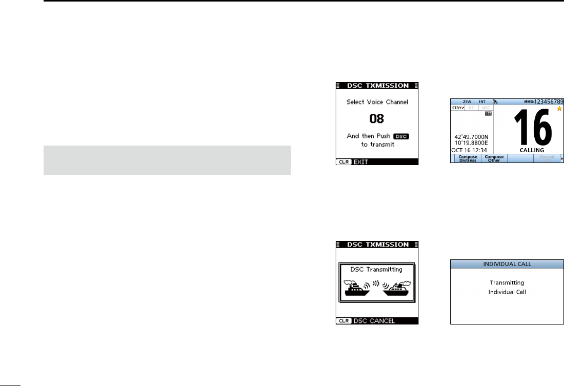
72
8DSC OPERATION
New2001
When the optional MA-500TR class b ais transponder
is connected to your transceiver, you can transmit an
Individual DSC call to a selected AIS target, without entering
the target’s MMSI code. In this case, the call type is
automatically set to Routine.
See page XX for connecting instructions.
NOTE: To ensure correct operation of the DSC function,
make sure you correctly set the CH70 SQL Level. (p. XX)
Step 1: Operating the Transponder
1. Select an AIS target on the plotter, target list or danger
list display.
• You can also go to the next step whenever the detail screen
of the AIS target is displayed.
• Conrm the transceiver is in the normal operating mode.
Otherwise, you cannot make an Individual DSC call using the
transponder.
2. Push [DSC] to display the Voice channel selection
screen, and then push [Y]/[Z] to select a desired Voice
channel.*
• Voice channels are already preset into the transponder in
recommended order.
* When a coast station is selected in step 1, a Voice channel
will be specied by the coast station, therefore you cannot
change the channel. The transponder will display “Voice
Channel is specied by the Base station,” in this case.
3. Push [DSC] to transmit an Individual DSC call to the
AIS target.
• If Channel 70 is busy, the transceiver stands by until the
channel becomes clear.
• If the transceiver cannot make the call, the transponder will
display “DSC Transmission FAILED.”
■Making an Individual call using an AIS transponder
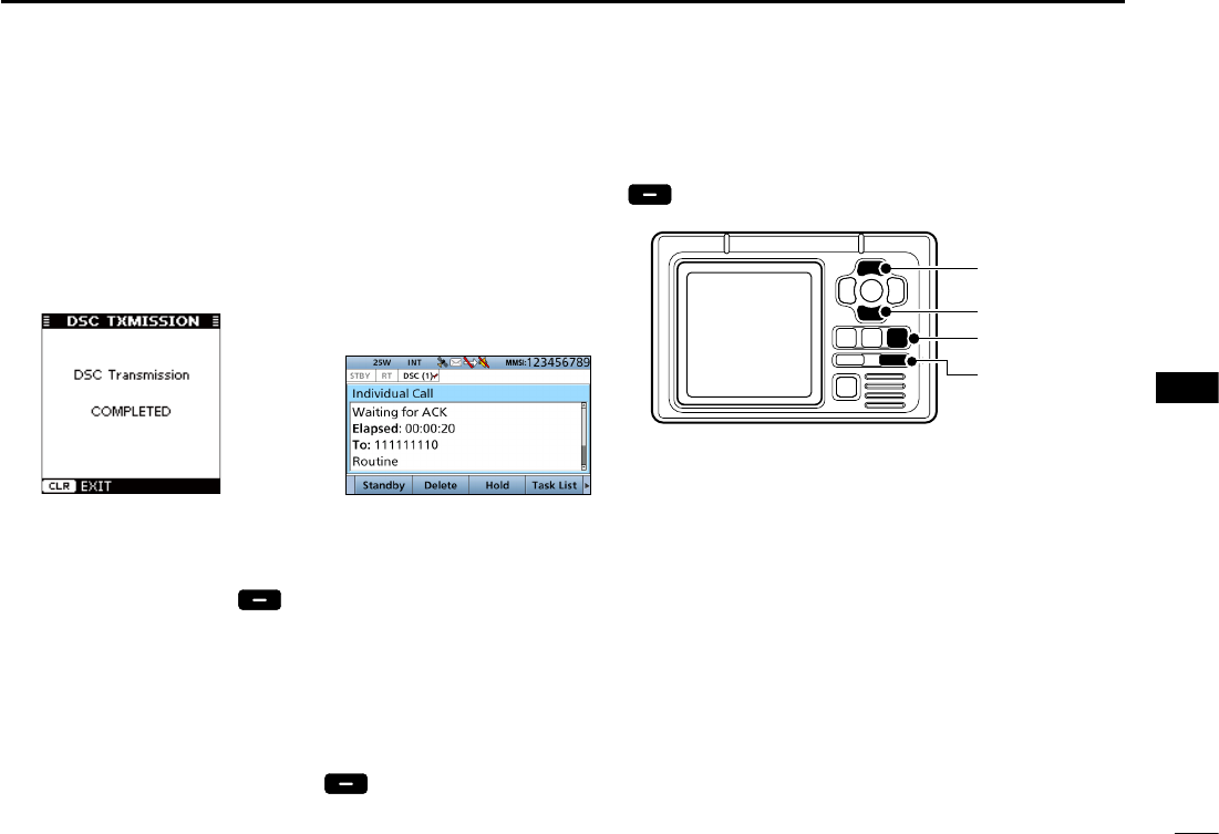
73
8
DSC OPERATION
New2001
1
2
3
4
5
6
7
8
9
10
11
12
13
14
15
16
4. After making the Individual DSC call, the transponder
will display “DSC Transmission COMPLETED.”
• Push [CLEAR] to return to the screen displayed before you
entered the Voice channel selection screen in step 2.
• The transceiver stands by on Channel 70 until an
acknowledgement is received.
Step 1: Operating the Transceiver
5. When the acknowledgement is received, alarm sounds.
z If the acknowledgement ‘Able to comply’ is received,
push [ALARM OFF] to stop the alarm, and then
select the Intership channel specied in step 2.
• A different Intership channel will be selected if the station
you called cannot use the channel.
• To reply, push [PTT] and speak at a normal voice level.
• You can check the MMSI code or the name, if entered, of
the AIS target on the display.
z If the acknowledgement ‘Unable to comply’ is
received, push [ALARM OFF] to stop the alarm,
then “INDIVIDUAL CALL FAILED” is displayed.
6. After the communication is finished, push [Standby]
to return to the normal operating mode.
[Y]
[Z]
[CLEAR]
[DSC]
TRANSPONDER
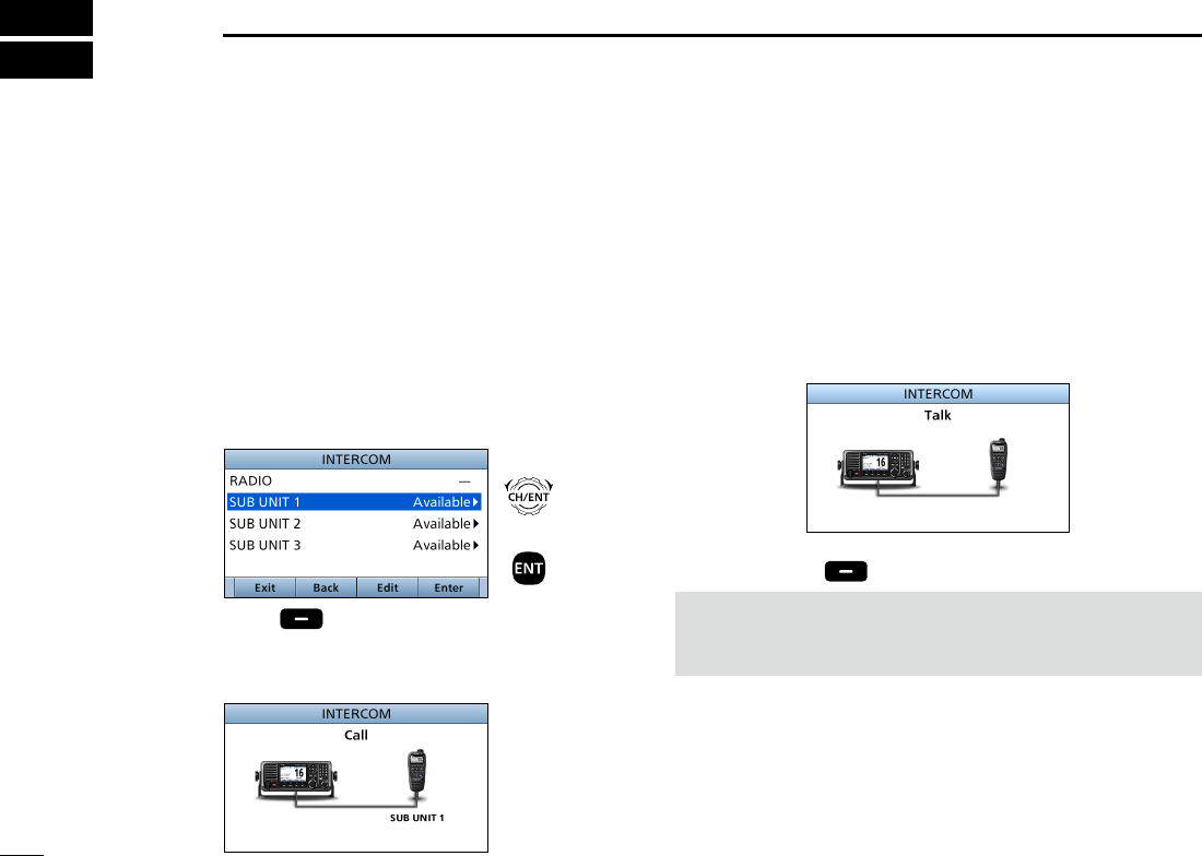
New2001
74
New2001
OTHER FUNCTIONS
9
■Using Intercom
The optional Intercom function enables you to talk
between the deck and the cabin. The optional HM-229
commandmicV™ is required for Intercom operation.
Connect the HM-229 as described on page 107.
• Transmitting is disabled while using the intercom.
• The received signal is muted while using the intercom.
1. Push [MENU].
2. Select “Intercom,” then push [ENT].
3. Select the unit, then push [ENT].
• Enters the Intercom mode.
4. Hold down [Call] to sound the intercom beeps.
• The transceiver and the command microphone sound beeps
while holding down [Call].
• “Call” is displayed.
5. After releasing [Call], hold down [PTT] and speak into
the microphone at a normal voice level.
• “ Talk” is displayed.
L
To adjust the transceiver’s intercom volume level, rotate
[VOL/SQL].
L To adjust the HM-229’s intercom volume level, rotate [VOL/
SQL] (Dial) on the HM-229.
6. After releasing [PTT], you can hear the response
through the speaker.
7. Push [EXIT] to return to the Main screen.
NOTE: While in the Intercom mode, the transmit and
receive functions are disabled. When the transceiver is
transmitting, the Intercom function is disabled.
+
Push
Rotate
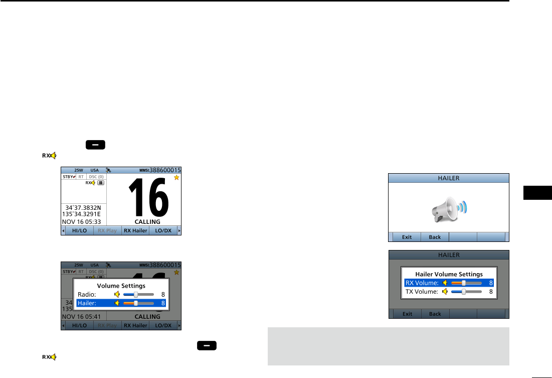
New2001
75
9
OTHER FUNCTIONS
New2001
1
2
3
4
5
6
7
8
9
10
11
12
13
14
15
16
■Using the RX Hailer
The RX Hailer function enables you to hear the received
audio on the deck or bridge through a Hailer speaker.
Connect an external hailer speaker as described on page XX.
1. Push [Ω] or [≈] until [
RX Hailer
] is displayed in the
Software Key area.
2. Push
[RX Hailer]
to enter the RX Hailer mode.
• The “ ”icon is displayed.
L Push [VOL/SQL] to open the volume adjustment screen.
3. To exit the RX hailer mode, push
[RX Hailer] .
• The “ ”icon disappears.
■Using the Hailer
You can talk without leaving the bridge by using the 2 way
hailer function.
Connect an external hailer speaker as described on page XX.
• You cannot transmit while using the hailer.
1. Push [MENU].
2. Select “Hailer,” then push [ENT].
• Hailer screen is displayed.
3. Hold down [PTT] and speak at your normal voice level.
4. While holding down
[PTT], the screen shown
to the right is displayed.
L Push [VOL/SQL] to open
the volume adjustment
screen.
NOTE: While in the hailer mode, the transmit and
receive functions are disabled. When the transceiver is
transmitting, the hailer function is disabled.
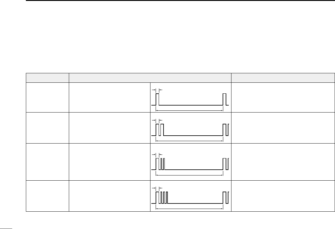
7676
9OTHER FUNCTIONS
■Using the Horn
DUsing the Automatic Foghorn
The Automatic Foghorn function sounds a horn repeatedly
until the function is turned OFF.
TYPE PATTERN USAGE
UNDERWAY
STOP
SAIL
TOW
One 5-second blasts every 120
seconds.
Two 5-second blasts (separated
by 2 seconds) every 120
seconds.
One 5-second blast followed
by two 1-second blasts (each
separated by 2 seconds) every
120 seconds.
One 5-second blast followed
by three 1-second blasts (each
separated by 2-seconds) every
120 seconds.
Motor vessel underway and making way.
Motor vessel underway but stopped (not
making way).
Sailing vessel underway, shing vessel
(underway or anchored), vessel not under
command, a vessel restricted in her ability
to maneuver (underway or at anchor), or a
vessel towing or pushing another ahead.
Vessel under tow (manned).
5s1
120s
5s1
2s
1s
120s
5s1
2s
1s
120s
5s1
2s 120s
The foghorn outputs from the hailer speaker. To use this
function, the hailer speaker must be connected to the
transceiver. See page XX for connection details.
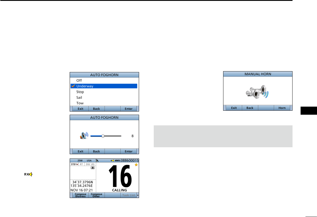
77
9
OTHER FUNCTIONS
New2001
1
2
3
4
5
6
7
8
9
10
11
12
13
14
15
16
1. Push [MENU].
2. Select “Auto Foghorn:,” and then push [ENT].
(Horn > Auto Foghorn:)
3. Select the foghorn
pattern, then push
[ENT].
4. Rotate [CH/ENT] to
adjust the foghorn level.
5. Push [Exit] to return to
the Main screen.
• The “ ”icon is
displayed.
L To turn OFF the Auto Foghorn, select “Off” in the “Auto
Foghorn:” menu.
DManual Horn function
1. Push [MENU].
2. Select “Manual Horn” then push [ENT].
(Horn > Manual Horn:)
3. Hold down [Horn] to
sound a horn.
• While holding down [Horn],
the horn sounds, and the
screen shown to the right
is displayed.
• To adjust the horn volume
level, rotate dial.
4. Push [EXIT] to return to the Main screen.
NOTE: While in the Horn mode, the transmit and
receive functions are disabled. When the transceiver is
transmitting, the Horn function is disabled.
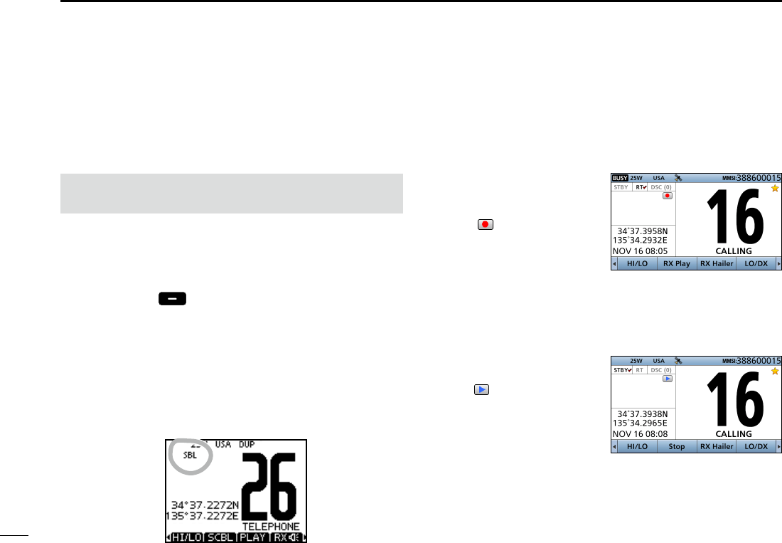
■Using the voice recorder
The transceiver has an automatic recording function that
can record the last 120 seconds of the receiving audio. You
can playback the audio that you could not hear clearly.
z Starts recording
automatically when the
signal is received.
• The “ ” icon is displayed
while recording.
• Stops recording 3 seconds
after the signal disappears.
• Stops recording when the channel is changed.
• The recorded voice data is erased when the transceiver is
turned OFF.
DPlayback the recorded voice
z Push [RX Play] to playback
the recorded voice.
• The “ ” icon is displayed while
playing.
z Push [Stop] to stop playing
back the recorded voice.
78
New2001
78
9OTHER FUNCTIONS
■ Using the Voice Scrambler
The Voice Scrambler provides private communications. In
order to receive or send scrambled transmissions, you must
activate the scrambler function. You also need to set the
scrambler code in the Menu screen. (p. 102)
The scrambler function automatically turns OFF when
Channel 16 or 70 is selected.
1. Select an operating channel except Channel 16, 70 or
weather channels.
2. Push [Ω] or [≈] until [
SCBL
] is displayed in the Software
Key area.
3.
Push [SCBL]
to turn the Voice Scrambler ON or
OFF.
• The “SBL” icon is displayed when the voice scrambler is ON.
DSetting scrambler codes
Set the code between 1 and 32 in the Menu screen. In order
to understand each other, all transceivers in your group must
have the same scramble code. See page XX for scrambler
code setting details.

79
9
OTHER FUNCTIONS
New2001
1
2
3
4
5
6
7
8
9
10
11
12
13
14
15
16
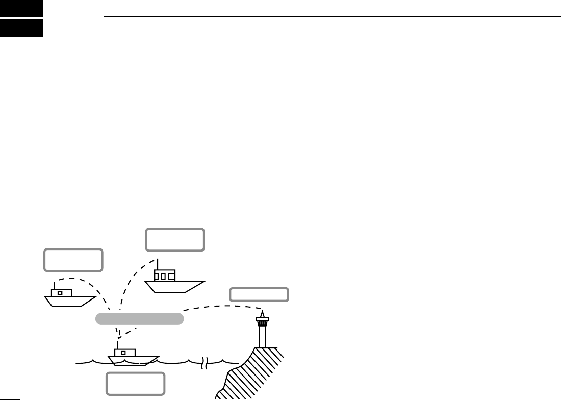
8080
AIS RECEIVER
10
■About AIS
AIS (The automatic identication system) is primarily used
for collision-risk management and navigation safety. It
automatically transmits and receives vessel information,
such as the vessel name, MMSI code, vessel type, position
data, speed, course, destination and more. Information is
exchanged among the vessels and/or base stations on the
VHF maritime mobile band. The information helps to identify
other nearby vessels or stations by displaying the received
data on a plotter or a radar screen.
■AIS Classes
There are 7 types of AIS stations; vessels, base stations,
Search and Rescue (SAR), Aids to Navigation (AtoN),
Search and Rescue Transmitter (AIS-SART), MOB (Man
OverBoard) and EPIRB (Emergency Position Indicating
Radio Beacon)- AIS.
There are two classes of AIS units, which are installed on
vessels; Class A and Class B.
Under the Safety Of Life At Sea (SOLAS) convention, all
SOLAS vessels, as described below, are required to install a
Class A AIS transponder:
• Upwards of 300 gross tonnage engaged on international
voyages.
• Passenger vessels, irrespective of size, engaged on
international voyages.
• Upwards of 500 gross tonnage not engaged on
international voyages.
A Class B AIS transponder is designed to be interoperability
with Class A units, but not to impact the Class A network.
Many commercial vessels, and some leisure craft, not
classied as requiring a Class A unit, choose to install a
Class B unit to avoid accidents at sea.
Other vessel
(Class A AIS)
Other vessel
(Class B AIS)
Vessel Information
Your vessel
(Class B AIS)
Base Station
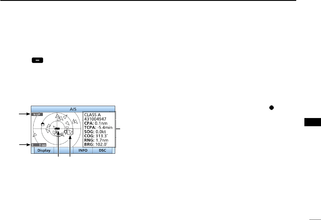
8181
10
AIS RECEIVER
■Function display
There are 3 types of function display; plotter, target list and
danger list. Select the display type using the [Display] key.
zPush [AIS] to display the Plotter screen.
DPlotter screen
If the GPS is connected and it receives signals from a satellite,
the plotter screen shows the display range and the icons of the
AIS targets.
q
t
r
e w
q INFORMATION
Display the selected target’s information.
w TARGET BOX
Shows the selected AIS target.
L When a target box is displayed, push [ENT] to display the
detail screen of the selected AIS target.
e YOUR VESSEL ICON
Displayed
in the center of the screen.
L When “N-UP” is displayed, the vessel icon automatically
points in the direction you are heading, in 45 degrees steps.
L When “COG-UP” is displayed, the vessel icon constantly
points to the top of the plotter screen.
L When your vessel moves less than 2 knots, the “ ” icon is
displayed.
r DISPLAY RANGE
Shows the selected display range.
Push [Range] to select display range.
L 0.125, 0.25, 0.5, 0.75, 1.5, 3, 6, 12, 24 nm (nautical miles) are
selectable.
t DISPLAY TYPE
Shows the selected display type. You can select the
display type from “AIS SET” in the menu screen (p. 88)
L When “N-UP” is displayed, the top of the plotter screen
represents North.
L When “COG-UP” is displayed, the top of the plotter screen
represents the direction your course is heading.
1
2
3
4
6
7
8
10
11
12
13
14
15
16
4
9
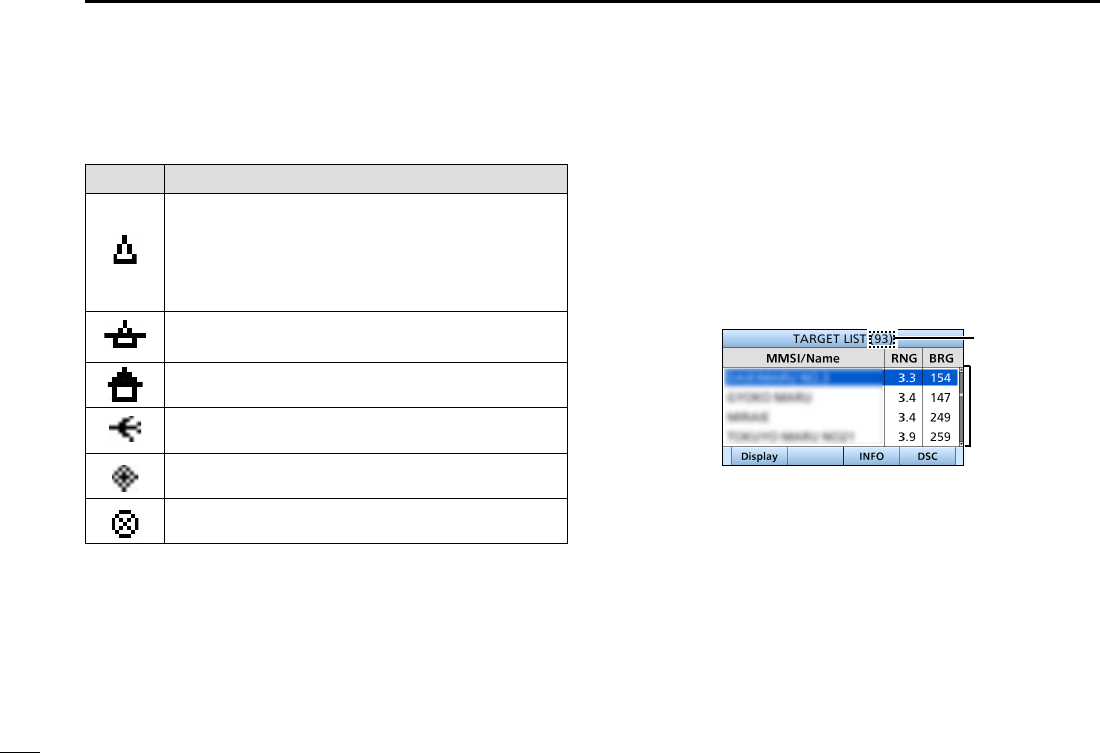
82
10 AIS RECEIVER
New2001
Function display (Continued)
• Description of the icons
Icon Description
AIS target: Vessel
The tip of the target triangle automatically points
in the direction it’s heading.
The icon blinks when the AIS target is closer than
your CPA and TCPA settings. (Dangerous target)
AIS target: Lost target*
The target triangle is marked with a diagonal line.
AIS target: Base Station
AIS target: Search and Rescue (SAR)
AIS target: Aids to Navigation (AtoN)
AIS target: AIS-SART, MOB and EPIRB-AIS
* A vessel is regarded as a “Lost target” after a specied period of
time has passed since the vessel last transmitted data.
The “Lost target” icon disappears from the plotter screen 6 minutes
and 40 seconds after the vessel was regarded as a “Lost target.”
Ask your dealer for details.
DTarget list screen
In the plotter screen, push [DISP] to switch to the target list
screen, which shows all AIS targets being detected by the
transponder.
The AIS target data is sorted by the distance from your
vessel, and the closest target is located on the top of the list.
• Rotate [CH/ENT] to select an AIS target.
• Push [INFO] to display the detail screen of the selected AIS target.
(p. XX)
• Push [DSC] to transmit DSC call to selected AIS target.
q
w
q THE NUMBER OF TARGETS
Shows the number of AIS targets which are being
detected by the transceiver.
w TARGET INFORMATION
Shows the following AIS target information:
• MMSI code or name.
• Range (RNG) from your vessel to the target
(unit: nautical mile).
• Bearing (BRG) from your vessel to the target (unit:
degree).
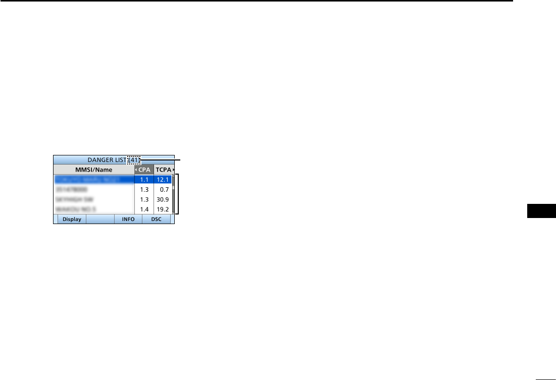
83
10
AIS RECEIVER
New2001
1
2
3
4
5
6
7
8
9
10
11
12
13
14
15
16
DDanger list screen
In the target list display, push [DISP] to switch to the danger
list screen, which helps you to nd any dangerous target
whose CPA is within 6 nm (nautical miles) and TCPA is
within 60 minutes of your vessel.
• Rotate [CH/ENT] to select an AIS target.
• Push [INFO] to display the detail screen of the selected AIS target.
(p. XX)
• Push [DSC] to transmit DSC call to selected AIS target.
q
w
q THE NUMBER OF DANGEROUS TARGETS
Shows the number of AIS targets which are being
detected by the transceiver.
w DANGER TARGET INFORMATION
Shows the following dangerous target information:
• MMSI code or name.
• CPA: Closest Point of Approach (unit: nautical mile).
• TCPA: Time to CPA (unit: minute).
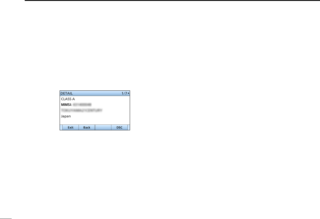
84
10 AIS RECEIVER
New2001
■About the detail screen
The detail screen displays the information about the selected
AIS target. The contents differ, depending on the AIS class.
1. Select an AIS target in the target list screen, danger list
screen, or plotter screen then push [INFO] or [ENT].
• The detail screen is displayed.
• Rotate [CH/ENT] to scroll the page.
D Content lists of Class A vessels’ DETAIL
screens
• AIS Class
• MMSI Code
• Ship Name
• Country Name
• Call Sign
• IMO Number
• CPA (Closest Point of
Approach)
• TCPA (Time to CPA)
• Position
(Latitude,Longitude)
• Speed Over Ground
• Course Over Ground
• Heading
• Position Accuracy
(H: High, L: Low)
• Range
• Bearing
• Rate Of Turn
• Bow to Antenna length
• Stern to Antenna length
• Port side to Antenna length
• Starboard side to Antenna
length
• Length
• Beam
• Draught
• Type of Ship
• Navigation Status
• Destination
• Date
• Time

85
10
AIS RECEIVER
New2001
1
2
3
4
5
6
7
8
9
10
11
12
13
14
15
16
D Content lists of Class B vessels’ DETAIL
screens
• AIS Class
• MMSI Code
• Ship Name
• Country Name
• Call Sign
• Vendor ID
• CPA (Closest Point of
Approach)
• TCPA (Time to CPA)
• Position (Latitude, Longitude)
• Speed Over Ground
• Course Over Ground
• Heading
• Position Accuracy
(H: High, L: Low)
• Range
• Bearing
• Bow to Antenna length
• Stern to Antenna length
• Port side to Antenna length
• Starboard side to Antenna
length
• Length
• Beam
• Type of Ship
D Content lists of Base Station targets’
DETAIL screens
• AIS Class
• MMSI Code
• Position (Latitude,Longitude)
• Position Accuracy
(H: High, L: Low)
• Range
• Bearing
D
Content lists of SAR targets’ DETAIL screens
• AIS Class
• MMSI Code
•
Position (Latitude, Longitude)
• Speed Over Ground
• Course Over Ground
• Position Accuracy
(H: High, L: Low)
• Range
• Bearing
• Altitude
D Content lists of AtoN targets’ DETAIL
screens
• AIS Class
(AtoN existence (REAL, VIRTUAL))
• MMSI Code
• Target Name
• CPA (Closest Point of Approach)
• TCPA (Time to CPA)
• Position (Latitude, Longitude)
• Position Accuracy
(H: High, L: Low)
• Range
• Bearing
• Bow to Antenna length
• Stern to Antenna length
• Port side to Antenna length
• Starboard side to Antenna
length
• Length
• Beam
• Position Indicator
(ON POS : ON Position,
OFF POS : OFF Position)
• Type of AtoN
D Content lists of AIS-SART targets’ DETAIL
screens
• Type of AIS Target
• MMSI Code
• Call Sign
• IMO Number
• Closest Point of Approach
• TCPA (Time to CPA)
• Position (Latitude, Longitude)
• Speed Over Ground
• Course Over Ground
• Heading
• Position Accuracy
(H: High, L: Low)
• Range
• Bearing
• Rate Of Turn
• Bow to Antenna length
• Stern to Antenna length
• Port side to Antenna length
• Starboard side to Antenna
length
• Length
• Beam
• Draught
• Type of Ship
• Navigation Status
• Destination
• Date
• Time
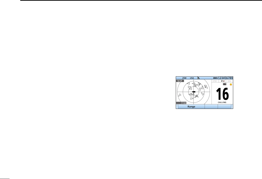
New2001
86
10 AIS RECEIVER
New2001
DAIS combo screen
You can display the AIS plotter during basic operation.
(p XX)
•
Push [AIS] to display the
AIS plotter on the left side of the
screen
.
• Rotate [CH/ENT] to select an operating channel.
• Push [Ω]/[≈] to select a vessel.
• Push [Range] to select display range
• Push [CLR] to exit the AIS combo screen.
D Content lists of MOB targets’ DETAIL screens
• Type of AIS Target
• MMSI Code
• Call Sign
• IMO Number
• Closest Point of Approach
• TCPA (Time to CPA)
•
Position (Latitude, Longitude)
• Speed Over Ground
• Course Over Ground
• Heading
• Position Accuracy
(H: High, L: Low)
• Range
• Bearing
• Rate Of Turn
• Bow to Antenna length
• Stern to Antenna length
• Port side to Antenna length
• Starboard side to Antenna
length
• Length
• Beam
• Draught
• Type of Ship
• Navigation Status
• Destination
• Date
• Time
D Content lists of EPIRB-AIS targets’ DETAIL
screens
• Type of AIS Target
• MMSI Code
• Call Sign
• IMO Number
• Closest Point of Approach
• TCPA (Time to CPA)
•
Position (Latitude, Longitude)
• Speed Over Ground
• Course Over Ground
• Heading
• Position Accuracy
(H: High, L: Low)
• Range
• Bearing
• Rate Of Turn
• Bow to Antenna length
• Stern to Antenna length
• Port side to Antenna length
• Starboard side to Antenna
length
• Length
• Beam
• Draught
• Type of Ship
• Navigation Status
• Destination
• Date
• Time
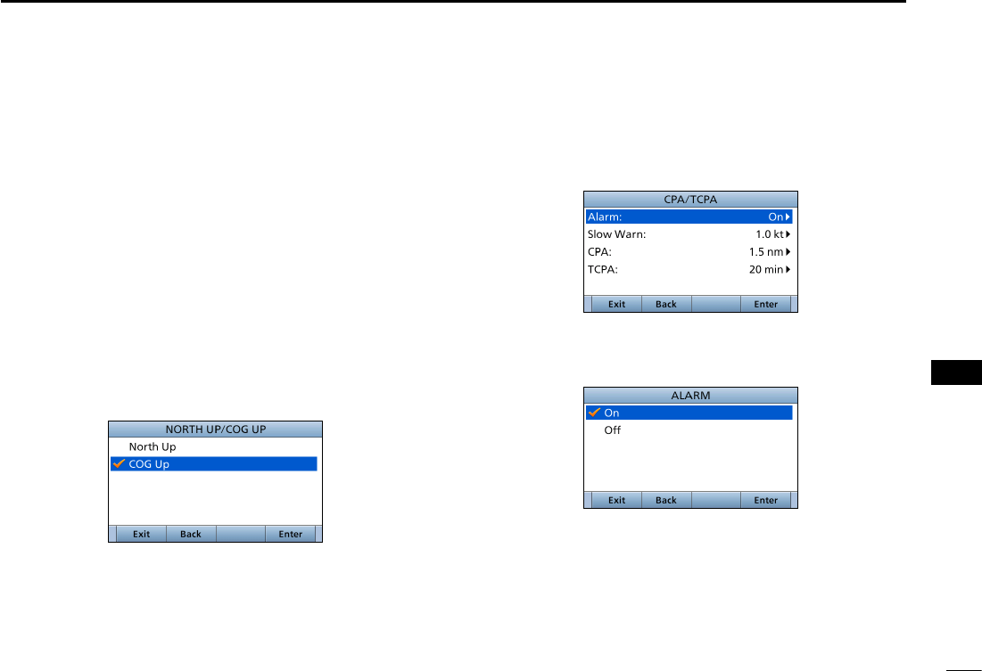
87
10
AIS RECEIVER
New2001
1
2
3
4
5
6
7
8
9
10
11
12
13
14
15
16
■AIS Settings
AIS settings can be customized from “AIS Settings” on the
menu screen.
1. Push [MENU].
2.
Select“AIS SET,” then push [ENT].
DNorth up/COG UP:
Select the display type for the AIS plotter.
L When “N-UP” is displayed, the top of the plotter display
represents North.
L When “COG-UP” is displayed, the top of the plotter display
represents the direction your course is heading.
• Push [EXIT] to return to the Main screen.
• Push [BACK] to return to the previous screen.
DCPA/TCPA
In this menu, you can edit alarm settings for AIS receiver.
• Alarm
You can turn the collision alarm function ON or OFF.
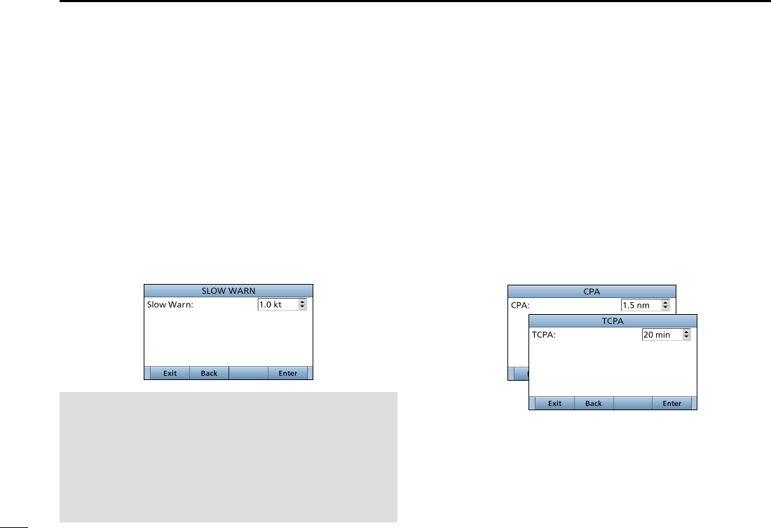
88
10 AIS RECEIVER
New2001
• CPA, TCPA
Enter CPA (Closest Point of Approach) and TCPA (Time to
CPA) values.
These settings help you nd a dangerous target to avoid a
collision. The icon blinks on the plotter display and/or the
alarm buzzer sounds, when the AIS target is closer than
your CPA and TCPA settings.
z
Rotate [CH/ENT] or push [Y]/[Z] to set the value.
• CPA: Set between 0.1 and 6.0 nm (in 0.1 nm steps)
(default: 1.5 nm)
• TCPA: Set between 1 and 60 minutes (in 1 minute steps)
(default: 20 min)
• Slow Warn
The GPS receiver calculated COG data of a vessel that is at
anchor or drifting is unreliable, and therefore the CPA and
TCPA data may not be calculated correctly. If a vessel is
anchored in your alarm zone, the unreliable data can cause
the collision alarm to sound many times, even if there is no
real danger. To prevent this, when the anchored vessel’s
SOG is less than this set value, the Slow Warn function
assumes that vessel’s COG is xed towards your vessel and
an alarm will sound.
z Rotate [CH/ENT] or push [Y]/[Z] to set the value between
0.1 and 4.9 kt (in 0.1 kt steps), or select OFF. (default: 1.0 kt)
NOTE: If other vessels at anchor or drifting come into your
alarm zone, the Slow Warn alarm will sound again. Only if
the previous vessel disappears from the Danger List
(p. 84), and then re-enters the list, can a new Slow Warn
or regular alarm sound, depending on the vessels SOG,
or CPA and TCPA. The Slow Warn function operates in
the same way if your vessel is at anchor and other vessels
enter your alarm zone area.
DCPA/TCPA (Continued)
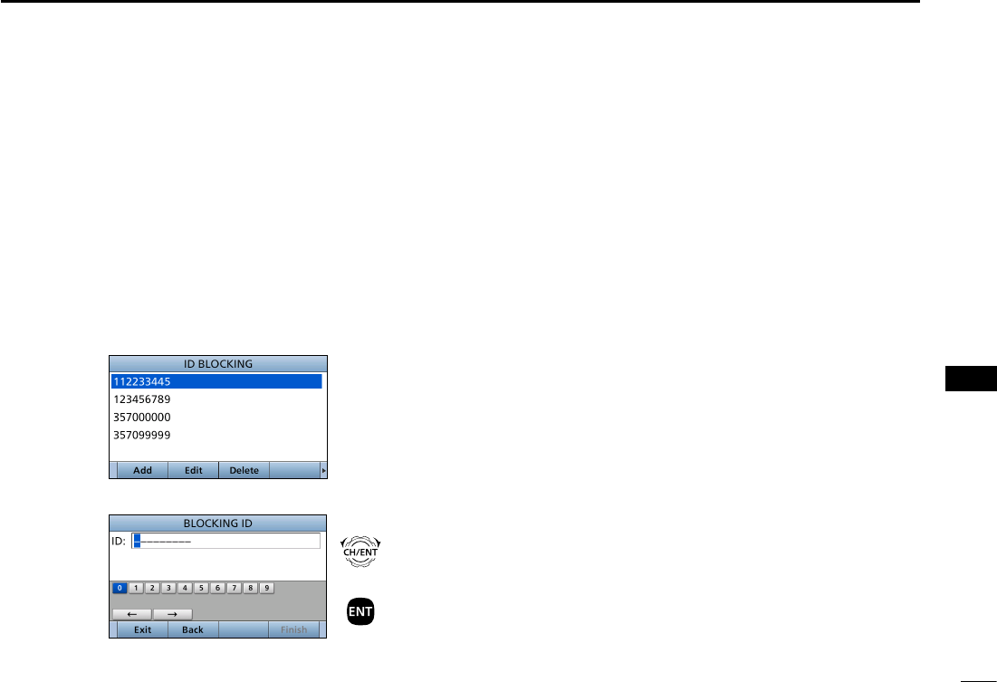
89
10
AIS RECEIVER
New2001
1
2
3
4
5
6
7
8
9
10
11
12
13
14
15
16
DID BLOCKING
The transceiver blocks AIS transponders that are entered
into the ID blocking list. Enter your vessel’s transponder ID
or other vessel’s transponder IDs if necessary to prevent the
transceiver from detecting them as dangerous targets.
You can enter maximum of 10 transponder IDs.
• Entering an ID
1. Push [MENU].
2. Select “ID Blocking,” then push [ENT].
(AIS Settings > ID Blocking)
• The blocked AIS transponder’s ID is displayed.
• “No ID” is displayed if there are no blocked AIS transponders
3. Push [Add] to start the ID entry
+
Push
Rotate
4. Push [Finish] to enter the ID.
• Editing an ID
1. Push [MENU].
2. Select “ID Blocking,” then push [ENT].
(AIS Settings > ID Blocking)
3. Select the ID to edit, then push [EDIT].
4. After editing, push [Finish] to set it.
• Deleting an ID
1. Push [MENU].
2. Select “ID Blocking,” then push [ENT].
(AIS Settings > ID Blocking)
3. Select th ID to delete, then push [Delete].
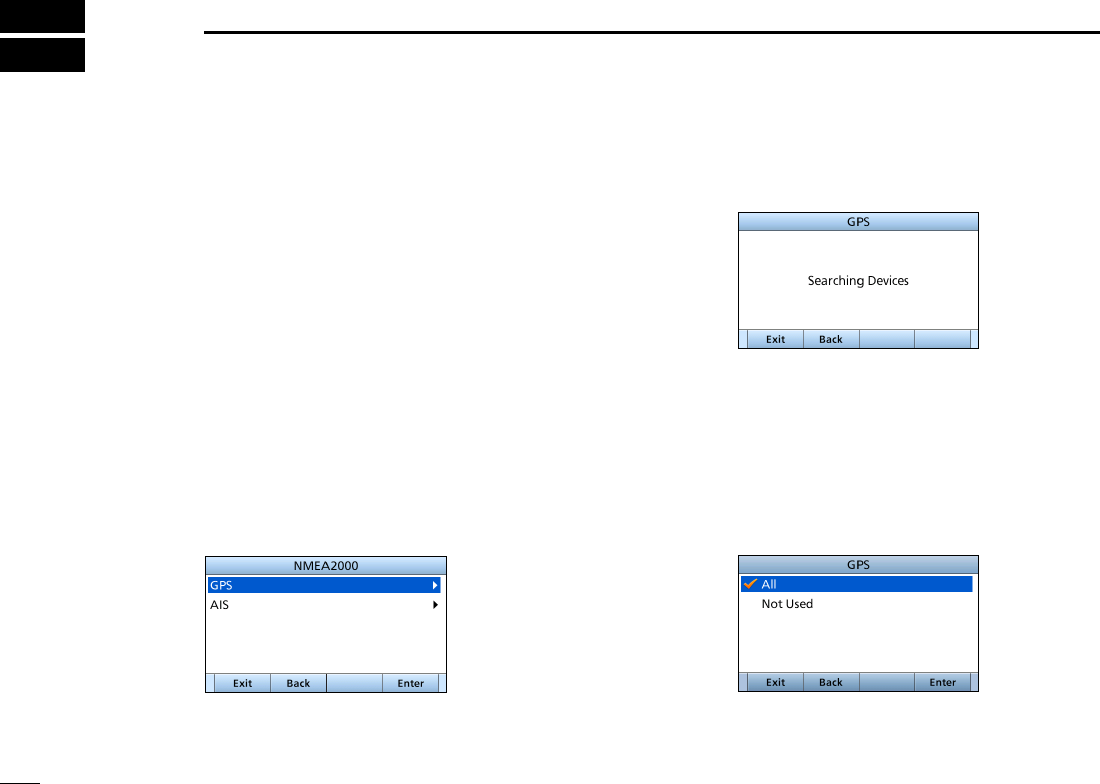
90
New2001
NMEA 2000 CONNECTION
11
3. The transceiver starts searching the devices connected
to NMEA 2000 network.
4. The list of connected device is displayed.
5. Select the device to send the data to transceiver and
push [ENT].
• Push [INFO] to display the detail of device.
• If the transceiver is connected to both NMEA 0183 and NMEA
2000 devices, the NMEA 2000 device has priority. Select “Not
Used” if you want to use NMEA 0183 devices.
6. Push [EXIT] to return to the Main screen.
New2001
■Description
NMEA 2000 is a communication standard used to connect
various marine devices and display units in the vessel.
The IC-M506 can easily connect to a NMEA 2000 network
with its plug-and-play functionality, and display the
information provided from the devices on the network.
DNMEA 2000 settings
Select the sensors in NMEA 2000 network which sends data
to the transceiver.
1. P u s h [ M E N U ] .
2. Select “NMEA 2000,” then push [ENT].
(NMEA Settings > NMEA 2000)
Select the type of data from the menu screen and push
[ENT].
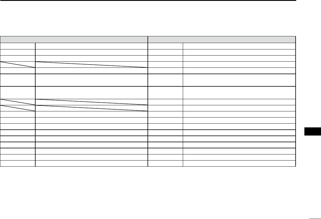
New2001
91
11
NMEA 2000 CONNECTION (Depending on versions)
New2001
1
2
3
4
5
6
7
8
9
10
11
12
13
14
15
16
DCompatible PGN list
Receive Transmit
059392 ISO Acknowledgement 059392 ISO Acknowledgement
059904 ISO Request 059904 ISO Request
060928 ISO Address Claim 060928 ISO Address Claim
126464 PGN List
126996 Product Information 126996 Product Information
129026 COG (course over ground) and SOG (speed
over ground) - Rapid Update
129026 COG (course over ground) and SOG (speed
over ground) - Rapid Update
129029 GNSS (Global Navigation Satellite System)
Position Data
129029 GNSS (Global Navigation Satellite System)
Position Data
129799 Radio Frequency/Mode/Power
129808 DSC Call Information
129038 AIS Class A Position Report 129038 AIS Class A Position Report
129039 AIS Class B Position Report 129039 AIS Class B Position Report
129040 AIS Class B Extended Position Report 129040 AIS Class B Extended Position Report
129041 AIS Aids to Navigation (AtoN) Report 129041 AIS Aids to Navigation (AtoN) Report
129793 AIS UTC and Date Report (Base Station) 129793 AIS UTC and Date Report (Base Station)
129794 AIS Class A Static and Voyage Related Data 129794 AIS Class A Static and Voyage Related Data
129798 AIS SAR Aircraft Position Report 129798 AIS SAR Aircraft Position Report
129809 AIS Class B “CS” Static Data Report, Part A 129809 AIS Class B “CS” Static Data Report, Part A
129810 AIS Class B “CS” Static Data Report, Part B 129810 AIS Class B “CS” Static Data Report, Part B
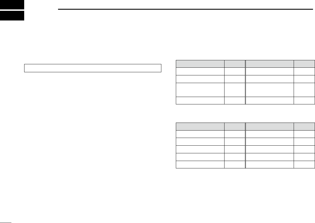
92
New2001New2001
MENU ITEMS
12
■Menu items
The Menu screen is constructed in a tree structure. (p. 10)
See page 99 to enter the Menu screen.
The following items are described in each section.
Refer to the specied pages for details.
DCompose Distress (p. 30)
DCompose Non-Distress
• Individual call (p. 42)
• All Ships (p. 45)
• Group (p. 46)
• Position (p. 47)
• Test (p. 50)
• Medical Transports (p. 52)
• Ships and Aircraft (p. 53)
DCompose DROBOSE (p. 36)
DDSC Log (pp. 69, 70)
DDSC Settings (p. 71)
DConguration
item Ref. item Ref.
Key Beep p. 93 Speaker p. 96
Key Assignment
Noise Cancel
UTC Offset Power SW From
Sub Unit
Inactivity Timer p. 94
DRadio Settings
item Ref. item Ref.
Scan Type p. 97 WX Alert* p. 98
Scan Timer p. 97 Voice Scrambler p. 99
Dual/Tri-Watch p. 97 Voice Record p. 76
Channel Group p. 97 FAV Settings
Call Channel p. 98 FAV on MIC
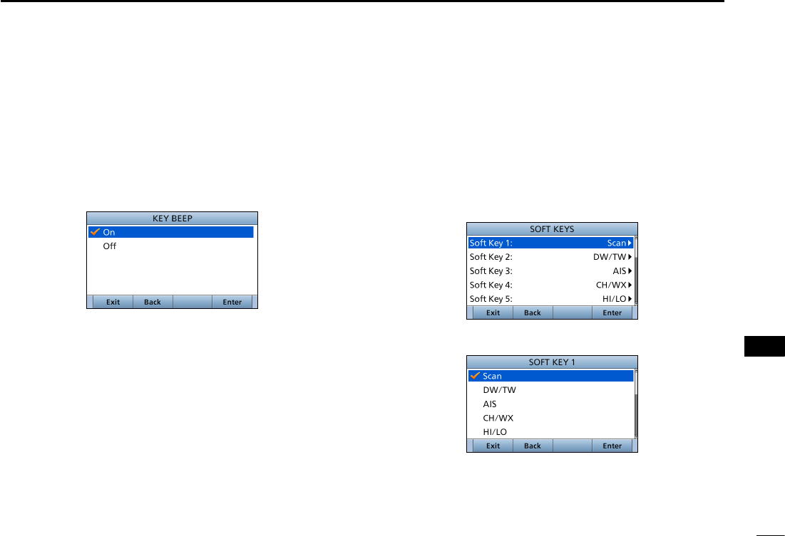
93
12
MENU ITEMS
New2001
1
2
3
4
5
6
7
8
9
10
11
12
13
14
15
16
New2001
■Conguration
DKey Beep
(Conguration > Key Beep:)
Turn the Key Beep function ON or OFF.
• On: Sounds a beep when pushing a key. (Default)
• Off: Does not sound a beep when pushing a key for
silent operation.
DKey Assignment
(Conguration > Key Assignment:)
Assign functions to Software keys. The assigned function
can be used when its key icon is displayed.
See page XX for details of the assignable key functions.
1. Select the Software key, then push [ENT].
2. Select the function to assign, then push [ENT].
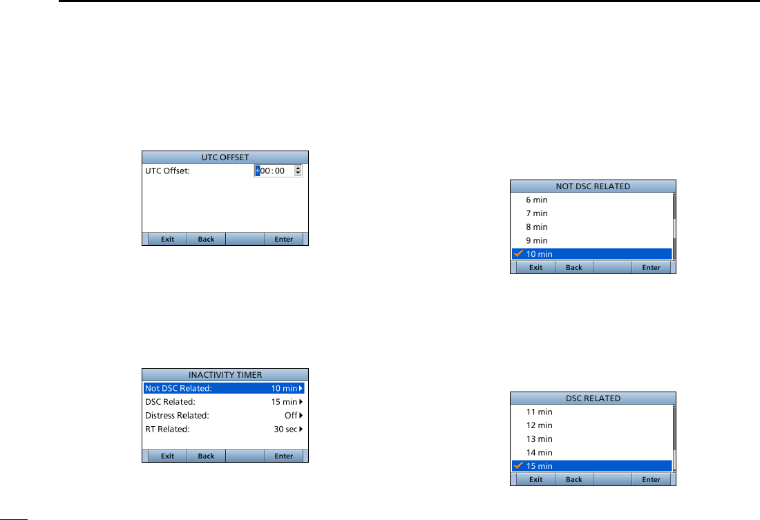
94
12 MENU ITEMS
New2001
• Not DSC Related
(Conguration > Inactivity Timer > Not DSC Related:)
The transceiver automatically returns to the Main screen if no
key is pushed for this set time period. (Default: 10 min)
This setting is for when the LCD displays a screen that is not
related to DSC screen other than the Main screen.
• DSC Related
(Conguration > Inactivity Timer > DSC Related:)
The transceiver automatically returns to the Main screen if no
key is pushed for this set time period. (Default: 15 min)
This setting is for when the LCD displays a screen that is
related to DSC.
DUTC Offset
(Conguration > UTC Offset:)
Set the offset time between UTC (Universal Time
Coordinated) and your local time to between –14:00 and
+14:00 (in 1 minute steps). (Default: 00:00)
DInactivity Timer
(Conguration > Inactivity Timer:)
Set the inactivity timer to between 1 and 15 minutes
(in 1 minute steps) or OFF.
The count down alarm sounds 10 seconds before the
Inactive timer activates.
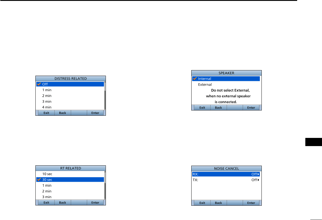
95
12
MENU ITEMS
New2001
1
2
3
4
5
6
7
8
9
10
11
12
13
14
15
16
D Speaker
(Conguration > Speaker:)
Select the speaker to use. (Detault: Internal)
When you connect an external speaker, and the
transceiver's internal speaker is not used, the internal
speaker is deactivated.
D Noise Cancel
(Conguration > Noise Cancel)
Set the Noise Cancel function for both receive and transmit.
RX: The function reduces noise component in your receive
signals for your smooth reception.
TX: It is effective to turn ON the TX noise cancel function
when you operate under a noisy surround area.
• Distress Related
(Conguration > Inactivity Timer > Distress Related:)
The transceiver automatically returns to the Main screen if
no key is pushed
for this set time period. (Default: Off)
This setting is for when the LCD displays a screen that is
related to a Distress call.
• RT Related
(Conguration > Inactivity Timer > RT Related:)
The transceiver automatically returns to the standby mode if
you push no key for this set time period. (Default: 30 sec)
This setting is for when the transceiver is in the Radio
Telephone mode.
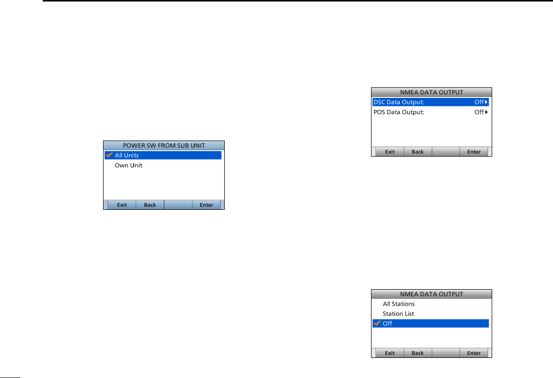
96
12 MENU ITEMS
New2001
D Power Switch from sub unit
(Conguration > Power SW From Sub Unit:)
Select weather or not to turn OFF the transceiver at same
time when you turn OFF the connected optional command
microphone or command station.
(Detault: All Units)
L The optional HM-195 or HM-229 command microphone or
RC-M600 command station is required to use this function.
All Units: When you turned OFF the command microphone
or command station, the transceiver is turned
OFF at same time.
Own Unit: The transceiver is not turned OFF even if
you turned OFF the command microphone or
command station.
DNMEA Data Output
(Conguration > NMEA Data Output)
Set the NMEA 0183 Output functions.
• DSC Data Output
(Conguration > NMEA Data Output > DSC Data Output)
Select an option for the DSC Data Output function.
When receiving a DSC call, the transceiver outputs the
NMEA sentences (DSC and DSE) from the NMEA 0183
output port to an external device.
• All Stations: Outputs the NMEA sentences.
• Station List: Outputs the NMEA sentences when you
receive a call from the station whose address
is entered in your Individual ID list.
• Off:
Does not output the NMEA sentences. (Default)
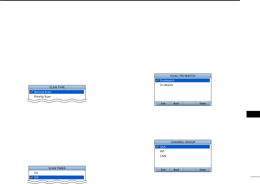
97
12
MENU ITEMS
New2001
1
2
3
4
5
6
7
8
9
10
11
12
13
14
15
16
■Radio Settings
DScan Type
(Radio Settings > Scan Type)
Select the Scan type to locate signals. (p. 21)
• Normal Scan: Sequentially searches all Favorite channels.
(Default for USA and Australian versions.)
• Priority Scan: Sequentially searches all Favorite channels,
while also monitoring Channel 16(Default).
(Default for the transceiver other than USA
and Australian versions.)
DScan Timer
(Radio Settings > Scan Timer)
Turn the Scan Resume timer ON or OFF.
• On: When a signal is detected on a channel, the scan
pauses for 5 seconds, and then resumes.
If the signal disappears in less than 5 seconds, the
scan immediately resumes.
• Off: When a signal is detected on a channel, the scan
pauses until the signal disappears, and then
resumes. (Default)
DDual/Tri-Watch
(Radio Settings > Dual/Tri-Watch)
Select the watch type. (p. 95)
• Dualwatch: The transceiver monitors Channel 16, while
listening or talking on another channel.
(Default)
• Tri-watch: The transceiver monitors Channel 16 and
the Call channel, while listening or talking on
another channel.
DChannel Group
(Radio Settings > Channel Group:)
Select a channel group suitable for your operating area.
Selectable channel group and the default setting may differ
depending on the transceiver version.
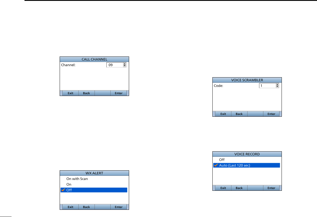
98
12 MENU ITEMS
New2001
DCall Channel
(Radio Settings > Call Channel)
You can set the Call channel with your most often-used
channel for quick recall. (p. <?>) (Default: Channel 16)
DWeather Alert
(For only USA and Australian versions.)
(Radio Settings > WX Alert:)
A NOAA broadcast station transmits a weather alert tone
before important weather information.
After the transceiver detects the alert, “WX” blinks until the
transceiver is operated.
• “WX ” displayed instead of “WX” when the function is set to
“On.”
(Default: “Off”)
DVoice Scrambler
(Displayed only when a Voice scrambler unit is installed.)
(Radio Settings > Voice Scrambler:)
Set the Voice Scrambler code to between 1 and 32.
In order to understand each other, all transceivers in your
group must have the same scramble code, as well as the
same scrambler unit.
DVoice Record
(Radio Settings > Voice Record:)
You can disable the Voice recorder (p. XX) by selecting “Off.”
(Default: Auto (Last 120 sec))
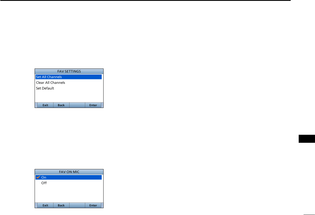
99
12
MENU ITEMS
New2001
1
2
3
4
5
6
7
8
9
10
11
12
13
14
15
16
DFAV Settings
(Radio Settings > FAV Settings)
Set the Favorite channel settings.
• Set All Channels: Sets all channels as Favorite channels.
• Clear All Channels: Clears all Favorite channels.
• Set Default: Returns to the default setting.
DFAV on MIC
(Radio Settings > FAV on MIC)
Turn the FAV on MIC function ON or OFF.
• On: Pushing [∫] or [√] on the supplied microphone scrolls
up and down through only the Favorite channels.
(Default)
• Off: Pushing [∫] or [√] on the supplied microphone scrolls
up and down through all channels.
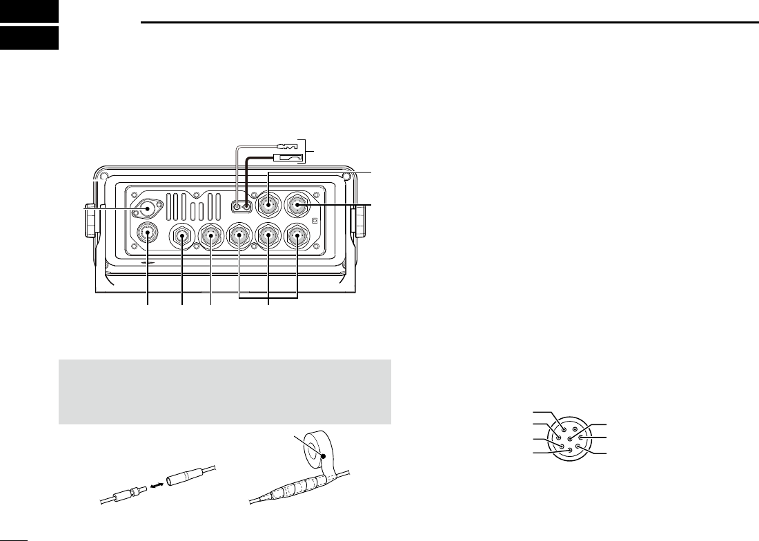
100100
CONNECTIONS AND MAINTENANCE
10
■Connections
q DC POWER CONNECTOR
Connects to a 13.8 V DC power source. (+: Red, –: Black)
CAUTION: After connecting the DC power cable, NMEA
leads, external speaker leads and Hailer leads, cover the
connector and leads with an adhesive tape, as shown
below, to prevent water seeping into the connection.
q
w
e
r
tyu
i
Rubber vulcanizing tape
w MICROPHONE CONNECTOR
Connects the supplied or optional HM-205 microphone.
e EXTERNAL SPEAKER CONNECTOR
Connects the optional SP-37 external speaker.
r COMMAND MICROPHONE/
COMMAND STATION CONNECTOR
Connects the optional Command microphone or Command
station.
t NMEA 0183 CONNECTORS
z Connects to NMEA 0183 Out lines of a PC or NMEA
0183 sentence format DSC or DSE compatible
navigation equipment, to receive position data from
other ships.
z Connects to NMEA 0183 In lines of a GPS receiver for
position data.
• A GPS receiver compatible with NMEA 0183 format RMC,
GGA, GNS, or GLL and VTG sentences is required. Ask
your dealer about suitable GPS receivers.
Transceiver’s rear panel view
Remote alarm output
NMEA 0183 IN (+)
NMEA 0183 IN (–)
GND
Remote alarm input/CLONE
NMEA 0183 OUT (+)
NMEA 0183 OUT (–)
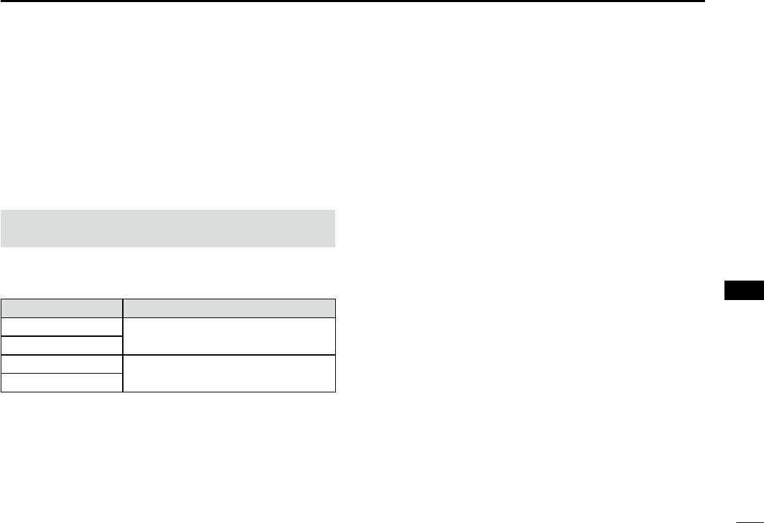
101101
10
CONNECTIONS AND MAINTENANCE
1
2
3
4
5
6
7
8
9
10
11
12
13
14
15
16
y NMEA 2000 CONNECTOR
Connects to the NMEA 2000 network.
u GPS RECEIVER CONNECTOR
Connects to a supplied GPS receiver.
i ANTENNA CONNECTOR
Connects to a marine VHF antenna with a PL-259 connector.
CAUTION: Transmitting without an antenna may damage
the transceiver.
DNMEA 0183 In/Out lines specications
PIN SPECIFICATIONS
NMEA 0183 OUT (+)
Output level: 5 V/40 mA maximum
(RS-422 balanced type)
NMEA 0183
OUT (–)
NMEA 0183
IN (+) Input level: Less than 2 mA
(at 2 V applied)
NMEA 0183
IN (–)
DConnect to the MA-500TR
Connect the transceiver to the high density D-Sub 15-pin
connector of the MA-500TR using the OPC-2014* cable.
You can make an Individual DSC call to the AIS target using
the transponder without entering the target’s MMSI code.
* The OPC-2014 is supplied with the MA-500TR
• Listener A (Data-H) lead (Yellow):
Connects to lead 3 of the OPC-2014.
• Listener B (Data-L) lead (Green):
Connects to lead 2 of the OPC-2014.
• Talker A (Data-H) lead (White):
Connects to lead 5 of the OPC-2014.
• Talker B (Data-L) lead (Brown):
Connects to lead 4 of the OPC-2014.
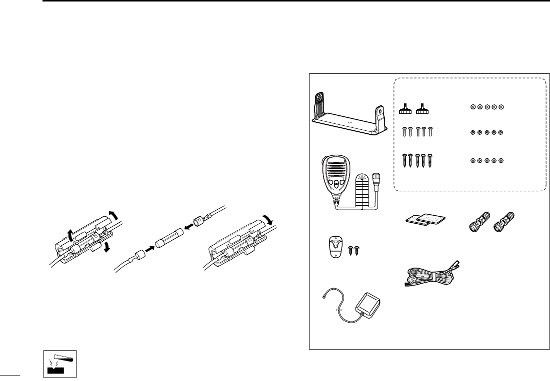
102
10 CONNECTIONS AND MAINTENANCE
New2001
■Antenna
A key element in the performance of any communication
system is the antenna. Ask your dealer about antennas and
the best place to mount them.
■Fuse replacement
One fuse is installed in the supplied DC power cable. If the
fuse blows, track down the source of the problem, repair it,
and replace the damaged fuse with a new one of the proper
rating.
Fuse rating: 10 A
■Cleaning
If the transceiver becomes dusty or dirty, wipe it clean with a
soft, dry cloth.
DO NOT use harsh solvents such as Benzine or
alcohol, as they will damage transceiver surfaces.
■Supplied accessories
Mounting bracket For the mounting bracket
Knob bolts Flat washers (M5)
Screws (M5×20 mm)
Spring washers (M5)
Microphone
Microphone hanger
and screws (3×16 mm)
Sponges Accessory connectors
6 pin 8 pin
DC power cable (OPC-1174A)*1
*1 Used for the
transceiverʼs
operation check.
(12 V DC only)
GPS receiver
Screws (5×20 mm) Nuts (M5)

103
10
CONNECTIONS AND MAINTENANCE
New2001
1
2
3
4
5
6
7
8
9
10
11
12
13
14
15
16
DAccessory connectors set up
The accessory connectors are used on the accessory
cables.
*2 Be sure to set this ring to keep the waterproof capability.
Solder
ACC Cable
These illustrations are for the
8-pin connector.
*2
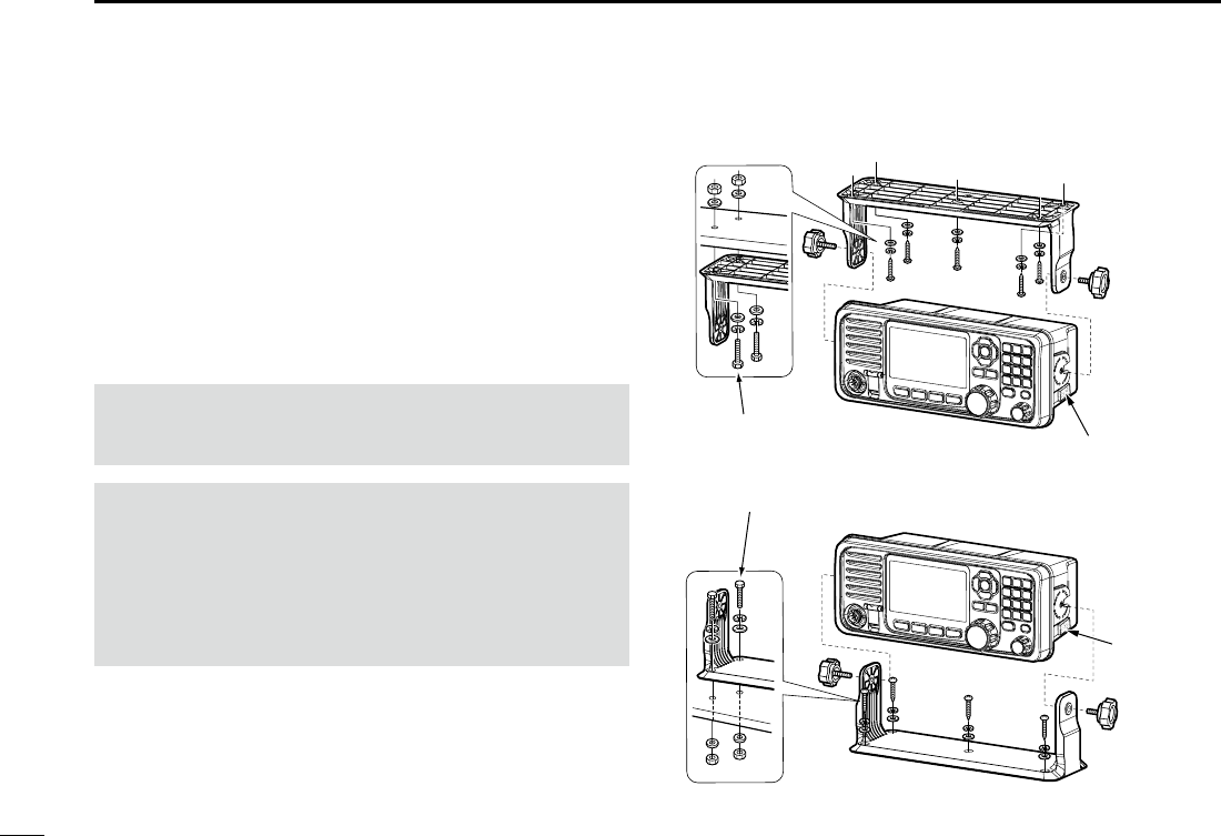
104
10 CONNECTIONS AND MAINTENANCE
New2001
■Mounting the transceiver
The supplied universal mounting bracket with your
transceiver enables overhead or at mounting.
• Mount the transceiver securely with the 4 supplied screws
(M5 × 20) to a surface that is more than 10 mm thick and
can support more than 5 kg.
• Mount the transceiver so its face is at 90° to your line of
sight when operating.
CAUTION: Keep the transceiver and microphone at least
1 meter (3.3 feet) away from your vessel’s magnetic
navigation compass.
NOTE:
• Check the installation angle; the function display may not
be easy to read at some angles.
• When mounting the transceiver on the place that is prone
to strong vibration, use the supplied sponges between
the transceiver and mounting bracket to reduce the effect
of the vibration.
Overhead mounting
Flat mounting
Sponges reduce the vibration effects.
See NOTE to the left.
*
Sponge*
These screws are shown as
only a mounting example.
Not supplied accessories.
Sponge*

105
10
CONNECTIONS AND MAINTENANCE
New2001
1
2
3
4
5
6
7
8
9
10
11
12
13
14
15
16
■MB-75 installation
An optional MB-75 flush mount kit is used for mounting
the transceiver to a at surface such as an instrument panel.
CAUTION: Keep the transceiver and microphone at least
1 meter (3.3 feet) away from your vessel’s magnetic
navigation compass.
1. Using the template on page XX, carefully cut a hole into
the instrument panel, or wherever you plan to mount
the transceiver.
2. Slide the transceiver through the hole, as shown below.
3. Attach the 2 supplied bolts (M5 × 8 mm) on either side
of the transceiver.
4. Attach the clamps on either side of the transceiver.
5. Make sure that the clamps align parallel to the
transceiver’s body.
6. Tighten the end bolts on the clamps (rotate clockwise)
so that the clamps press rmly against the inside of the
instrument control panel. (Torque: 0.6 N•m)
7. Tighten the locking nuts (rotate counterclockwise) so
that the transceiver is securely mounted in position as
below.
8. Connect the antenna and power cable, then return the
instrument control panel to its original place.
Supplied
bolt
Clamp
Locking
nut
End bolt
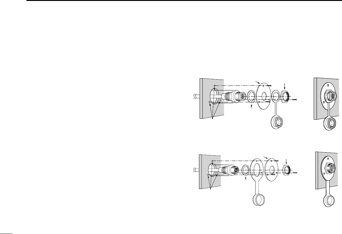
106106
10 CONNECTIONS AND MAINTENANCE
■Microphone installation
Connect the supplied or optional HM-205 and the optional
HM-195/HM-229 to the transceiver using the connection
cable that comes with the transceiver or the microphone.
The cable is required to operate the transceiver from a
longer distance. You can also install the cable connector as
a built-in plug on a cabinet or wall.
To operate from even longer distances, connect the optional
6 meter long OPC-1541 extension cable between the
transceiver and the microphone.* Up to two OPC-1541 can
be added.
* OPC-2384 is required to connect the transceiver and HM-195/HM-
229 command microphone or OPC-1541 extension cable.
DInstallation
1. Insert the connection cable connector into the
microphone connector or the command microphone
jack, and tighten the nut.
2. To use the cable connector as a wall socket, install it as
shown to the right.
3. Using the mounting base as a template, carefully
mark the holes where the cable and 3 screws will be
fastened.
4. Drill holes at these marks.
5. Install the mounting base using the supplied screws, as
shown below.
•HM-205
Gasket
Cap
Mounting base Nut
Screw holes
(approximately 2 (d) mm; 0.1 inches)
•HM-195/HM-229
Gasket
Cap
Mounting base Nut
Screw holes
(approximately 2 (d) mm;
0.1 inches)
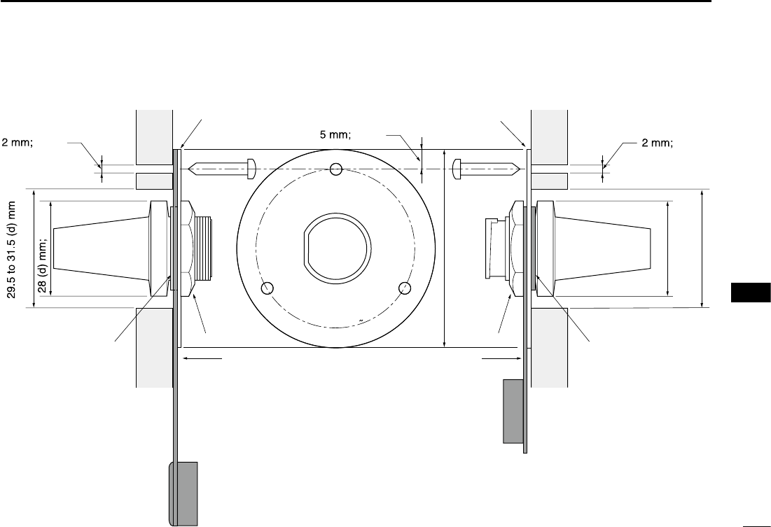
107
10
CONNECTIONS AND MAINTENANCE
New2001
1
2
3
4
5
6
7
8
9
10
11
12
13
14
15
16
Gasket
Mounting base
Cap
Nut
24 to 27 (d) mm
Gasket
Mounting base
Cap
Nut
(1.2 in)
1.1 in
0.1 in 0.2 in 0.1 in
50 (d) mm; 2 in
23 (d) mm; 0.9 in
(0.9 to 1.1 in)
•HM-195/HM-229 •HM-205

New2001
108
New2001New2001
SPECIFICATIONS AND OPTIONS
14
■Specications
All stated specications are subject to change without notice
or obligation.
IC-M605
DGeneral
• Frequency coverage: TX 156.025 ~ 161.600 MHz
RX 156.050 ~ 163.275 MHz
156.525 MHz (CH70/DSC)
• Mode:
FM (16K0G3E), DSC (16K0G2B)
•
Operating temperture range:
–20°C to +60°C (–4ºF to +140ºF)
• Current drain: TX high (25 W) 6.0 A maximum
RX Maximum audio 8.0 A*
• Power supply requirement: 13.8 V DC nominal (negative ground)
• Frequency stability: ±10 ppm
• Antenna impedance: 50 ˘ nominal
• Dimensions
(projections not included):
274 (W) × 114 (H) × 121.5 (D) mm
10.8 (W) × 4.5 (H) × 4.8 (D) inches
• Weight (approximately): 1.5 kg; 3.3 lb
*When options (command stations, command microphones, and
external speaker) are connected.
DTransmitter
• Output power: 25 W or 1 W
• Modulation system: Variable reactance frequency
modulation
• Maximum frequency
deviation: ±5 kHz
• Spurious emissions: Less than –70 dBc (High)
Less than –56 dBc (Low)
• Adjacent channel power: More than 70 dB
• Audio harmonic distortion: Less than 10% (at 60% deviation)
• Residual modulation: More than 40 dB
• Audio frequency response: +1 to –3 dB of 6 dB/octave range from
300 Hz to 2500 Hz
DReceiver
• Receive system: Double conversion superheterodyne
• Sensitivity:
FM: –13 dBµ (typical) (12 dB SINAD)
DSC (CH70): –3 dBµ emf (typical) (1% BER)
• Squelch sensitivity: Less than –7 dBµ
• Intermodulation:
FM: More than 80 dB
DSC (CH70): More than 73 dBµ emf (1% BER)
•
Spurious response
:
FM: More than 77 dB
DSC (CH70): More than 73 dBµ emf (1% BER)
•
Adjacent channel selectivity:
FM: More than 80 dB
DSC (CH70): More than 80 dBµ emf (1% BER)
• Audio output power: More than 15 W at 10% distortion into
a 4 ˘ load
• Ham and noise: More than 40 dB
• Audio frequency response: +1 to –3 dB of –6 dB/octave range
from 300 Hz to 3000 Hz

New2001
109
14
SPECIFICATIONS AND OPTIONS
New2001
1
2
3
4
5
6
7
8
9
10
11
12
13
14
15
16
New2001
IC-M605EURO
DGeneral
• Frequency coverage: TX 156.000 ~ 161.600 MHz
RX 156.000 ~ 163.425 MHz
156.525 MHz (CH70/DSC)
• Mode:
FM (16K0G3E), DSC (16K0G2B)
•
Operating temperature range:
–20°C to +60°C
• Current drain: TX high (25 W) 6.0 A maximum
RX Maximum audio 8.0 A*
• Power supply requirement: 13.8 V DC nominal (negative ground)
• Frequency error: Less than ±0.5 kHz
• Antenna impedance: 50 ˘ nominal
• Dimensions
(projections not included):
274 (W) × 114 (H) × 121.5 (D) mm
• Weight (approximately): 1.5 kg
*When options (command stations, command microphones, and
external speaker) are connected.
DTransmitter
• Output power: 25 W or 1 W
• Modulation system: Variable reactance frequency
modulation
• Maximum frequency
deviation: ±5 kHz
• Spurious emissions: Less than 0.25 μW
• Adjacent channel power: More than 70 dB
• Audio harmonic distortion: Less than 10% (at 60% deviation)
• Residual modulation: More than 40 dB
• Audio frequency response: +1 to –3 dB of 6 dB/octave range from
300 Hz to 3000 Hz
DReceiver
• Receive system: Double conversion superheterodyne
• Sensitivity:
FM: –5 dBµ emf (typical) (20 dB SINAD)
DSC (CH70): –3 dBµ emf (typical) (1% BER)
• Squelch sensitivity: Less than –2 dBµ emf
• Intermodulation:
FM: More than 75 dB
DSC (CH70): More than 73 dBµ emf (1% BER)
•
Spurious response
:
FM: More than 75 dB
DSC (CH70): More than 73 dBµ emf (1% BER)
•
Adjacent channel selectivity:
FM: More than 75 dB
DSC (CH70): More than 80 dBµ emf (1% BER)
• Audio output power: More than 15 W at 10% distortion into
a 4 ˘ load
• Ham and noise: More than 40 dB
• Audio frequency response: +1 to –3 dB of –6 dB/octave range
from 300 Hz to 3000 Hz
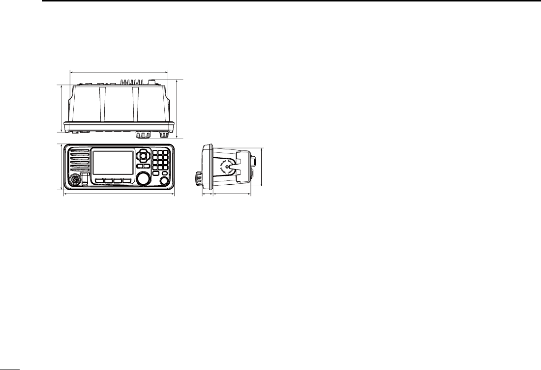
New2001
110
14 SPECIFICATIONS AND OPTIONS
New2001
■Options
DCommand stations and cables
•RC-M600 command station
The command station with the same front panel as the
transceiver. Mounting bracket , microphone, and 10 meter
(32.8 feet) connection cable included.
•OPC-2383 xxxxxxxx
10 meter (32.8 feet) cable to connect the transceiver and
RC-M600 command station.
•OPC-2377 xxxxxxxx
10 meter (32.8 feet) extension cable.
DMicrophone and cables
•HM-195B/HM-195SW commandmicIV™
External microphone-type controller. Provides optional
intercom operation. 6 meters (20 feet) microphone cable
and mounting base included.
HM-195B: Black
HM-195SW: Super White
•HM-229B/HM-229W commandmicV™
External microphone-type controller without [DISTRESS]
key.
HM-229B: Black
HM-229W: White
DDimensions Unit: mm (inch)
274 (10.8)
114 (4.5) 121.5 (4.8)
250 (9.8)
148.25 (5.8)
28 (1.1) 93.5 (3.7)
93.75 (3.7)

111
14
SPECIFICATIONS AND OPTIONS
New2001
1
2
3
4
5
6
7
8
9
10
11
12
13
14
15
16
New2001
•OPC-2384 xxxxxxxxxxxxx
The cable to connect the transceiver and HM-195 or
HM-229.
•OPC-1541 microphone extension cable
6 meters (20 feet) microphone extension cable for optional
HM-195 commandmicIV™. Up to two OPC-1541 can be
connected. Usable length is 18 meters (60 feet) maximum.
•HM-205B/HM-205RB speaker microphone
Equipped with [Y]/[Z] (channel up/down), [H/L], [16/C], and
[PTT] keys, a speaker and microphone.
DOthers
•SP-37 horn speaker
The external horn speaker. Connect using the supplied 6 pin
accessory connector that supplied with the transceiver.
•MA-500TR class b ais transponder
To transmit individual DSC calls to a selected AIS targets.
•MB-75 flush mount kit
To mount the transceiver to a panel.
•UX-241 gnss antenna
To receive the GPS signal.
•UT-112 voice scrambler unit
Ensures private communications. 32 codes are available.
Not available in some countries.
Ask your service center or technical dealer for installation
details.
•UT-251 ais receiver unit
The optional AIS unit for the version without AIS function.
Ask your service center or technical dealer for installation
details.

New2001
112
New2001
TROUBLESHOOTING
15
New2001
PROBLEM POSSIBLE CAUSE SOLUTION REF.
The transceiver does
not turn ON.
• Bad connection to the power supply.
• Fuse blows.
• Check the connection to the transceiver and
power supply.
• Repair the problem, and then replace the
fuse.
p. 86
p. 84
Little or no sound
comes from the
speaker.
• Squelch level is set too high.
• Volume level is set too low.
• The internal speaker is OFF.
• Set the squelch to the threshold point.
• Set the volume to a suitable level.
• Turn ON the internal speaker.
p. 15
p. 15
p. 81
You cannot transmit,
or cannot select high
power
.
• Some channels are set for low power or
receive only by regulations.
• The output power is set to low.
• Change channels.
• Push [HI/LO] to select high power.
pp. 13
93
p. 15
Scan does not start. • More than 2 favorite channels are not set. • Set the desired channels as Favorite
channels.
pp. 21,
78
No beep sounds. • The Key Beep function is OFF.
• Turn ON the Key Beep function.
p. 78
The Main screen is not
displayed at power ON.
• MMSI (DSC self ID) code is not set. • Set the MMSI (DSC self ID) code. p. 9
Individual or Group ID
cannot be set.
• The entered ID code is incorrect.
First digit must be set to between ʻ1ʼ and
ʻ9ʼ for the Individual ID.
First digit must be set to ʻ0ʼ for the Group
ID.
• Enter a correct ID code. pp. 23,
24
“??” blinks instead of
the position and time.
•
4 hours have passed after you manually
entered the position.
•
The GPS position is invalid.
• Enter the position. p. 25

New2001
113
15
TROUBLESHOOTING
New2001
1
2
3
4
5
6
7
8
9
10
11
12
13
14
15
16
New2001
PROBLEM POSSIBLE CAUSE SOLUTION REF.
“NO POSITION”
and “NO TIME” are
displayed instead of
the position and time.
• A GPS receiver is not
correctly
connected.
• The position and time have not been
manually entered.
• Check the GPS receiver connection.
• Enter the position and time.
p. 82
p. 25
Sensitivity is too low,
and only strong signals
can be heard.
•
The antenna is defective or the coaxial
cable connector is shorted or cut.
• Repair the problem and then reconnect to
the antenna connector.
pp. 82,
83
The communication
cannot be established.
•
The antenna is defective or the coaxial
cable connector is shorted or cut.
• Repair the problem and then reconnect to
the antenna connector.
pp. 82,
83
The transceiver is
locked up, and does
not respond.
• A software error has occured. • Turn OFF the DC power source, and then
turn it ON again.
p. 86
The transceiver does
not work.
• The transceiver's Phase Lock Loop is
unlocked.
• Contact your dealer.
—
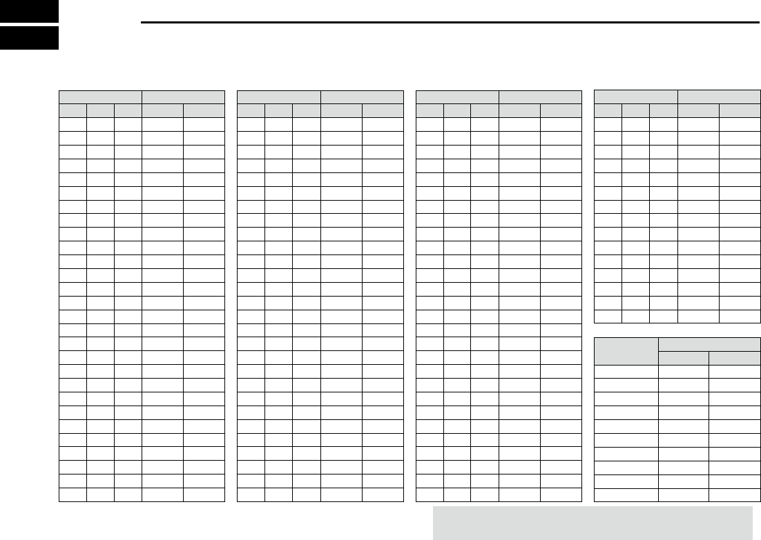
New2001New2001
CHANNEL LIST
16
Channel number Frequency (MHz)
03 156.150 160.75003
03A 156.150 156.150
156.200 160.80004
02 156.100 160.70002
04A 156.200 156.200
156.250 160.85005
05A 05A 156.250 156.250
06 06 156.300 156.30006
156.350 160.95007
07A 07A 156.350 156.350
08 08 156.400 156.40008
09 09 156.450 156.45009
10 10 156.500 156.50010
11 11 156.550 156.55011
12 12 156.600 156.60012
13*213*1
156.650 156.650
13
14 14
156.700 156.700
14
15*215*1
156.750 156.750
15*1
16 16
156.800 156.800
16
17*117*1
156.850 156.850
17
156.900 161.500
18
18A 18A
156.900 156.900
156.950 161.550
19
19A 19A 156.950 156.950
20 20*1157.000 161.60020
20A 157.000 157.000
01A 156.050 156.050
USA*5
01
156.050 160.65001
CAN
*4
Transmit Receive
INT
Channel number Frequency (MHz)
157.100 161.70022
22A 22A 157.100 157.100
23 157.150 161.75023
21b Rx only 161.650
23A 157.150 157.150
24 24 157.200 161.80024
25 25 157.250 161.85025
25b Rx only 161.850
26 26 157.300 161.90026
27 27 157.350 161.95027
28 28 157.400 162.00028
28b Rx only 162.000
60 156.025 160.62560
156.075 160.67561
61A 61A 156.075 156.075
156.125 160.72562
62A 156.125 156.125
156.175 160.77563
63A 156.175 156.175
64 156.225 160.82564
64A 64A 156.225 156.225
156.275 160.87565
65A 65A 156.275 156.27565A*4
156.325 160.92566
66A 66A*1156.325 156.32566A*4
67*267 156.375 156.37567
21A 21A 157.050 157.050
USA*5
21 157.050 161.65021
CAN
*4
TransmitReceive
INT
Channel number Frequency (MHz)
71 71 156.575 156.57571
72 72 156.625 156.62572
73 73 156.675 156.67573
70*370*3156.525 156.52570*3
74 74 156.725 156.72574
75*175*1156.775 156.77575*1
76*176*1156.825 156.82576*1
77*177*1156.875 156.87577
156.925 161.52578
78A 78A 156.925 156.925
156.975 161.57579
79A 79A 156.975 156.975
157.025 161.62580
80A 80A 157.025 157.025
157.075 161.67581
81A 81A 157.075 157.075
157.125 161.72582
82A 82A 157.125 157.125
83 157.175 161.77583
83A 83A 157.175 157.175
83b Rx only 161.775
84 84 157.225 161.82584
84A 157.225 157.225
85 85 157.275 161.87585
85A 157.275 157.275
86 86 157.325 161.92586
69 69 156.475 156.47569
68
USA*5
68 156.425 156.42568
CAN
*4
TransmitReceive
INT
Channel number Frequency (MHz)
88 88 157.425 162.02588
88A 157.425 157.425
87A 157.375 157.375
87 87 157.375 161.97587
86A
USA*5
157.325 157.325
CAN
*
4
TransmitReceive
INT
Frequency (MHz)
RX only 162.425
RX only 162.450
RX only 162.500
RX only 162.475
RX only 162.525
RX only 161.650
RX only 161.775
RX only 163.275
RX only 162.400
RX only 162.550
TransmitReceive
WX channel*7
4
5
6
3
7
8
9
10
2
1
37A*6157.850 157.85037A*6
P4*6161.425 161.425P4*6
*1 Low power only.*2 Momentary high power.
*3 DSC operation only.
*4 For only USA versions.*5 For only USA, UK, and Australian versions.
*6
UK Marina Channels: M1=37A (157.850 MHz), M2=P4 (161.425 MHz)
for only UK. versions. *7 For only USA and Australian versions.
NOTE: Simplex channels, 3, 21, 23, 61, 64, 81, 82, and 83
CANNOT be lawfully used by the general public in USA waters.
115
17
INFORMATION
New2001
1
2
3
4
5
6
7
8
9
10
11
12
13
14
15
16
17
■Country code list
• ISO 3166-1
Country Codes Country Codes
1Austria AT 18 Liechtenstein LI
2Belgium BE 19 Lithuania LT
3 Bulgaria BG 20 Luxembourg LU
4Croatia HR 21 Malta MT
5 Czech Republic CZ 22 Netherlands NL
6 Cyprus CY 23 Norway NO
7 Denmark DK 24 Poland PL
8Estonia EE 25 Portugal PT
9Finland FI 26 Romania RO
10 France FR 27 Slovakia SK
11 Germany DE 28 Slovenia SI
12 Greece GR 29 Spain ES
13 Hungary HU 30 Sweden SE
14 Iceland IS 31 Switzerland CH
15 Ireland IE 32 Turkey TR
16 Italy IT 33 United Kingdom GB
17 Latvia LV
■Disposal
The crossed-out wheeled-bin symbol on your
product, literature, or packaging reminds
you that in the European Union, all electrical
and electronic products, batteries, and
accumulators (rechargeable batteries) must be
taken to designated collection locations at the
end of their working life. Do not dispose of these products
as unsorted municipal waste. Dispose of them according to
the laws in your area.

New2001
116
New2001
INDEX
A
Accessory
Accessory connectors set up ......... 85
Supplied accessories ..................... 85
Handset (HS-98) ............................ 88
Speaker Microphone ........................ 5
Alarm Status ......................................73
Antenna ............................................. 84
B
Backlight function .............................. 17
Basic operation .................................. 13
C
Call log
Received Call log ........................... 69
Transmitted Call log ....................... 70
Channel
Call channel selecting .................... 13
Call channel setting ........................ 14
Channel 16 selecting...................... 13
Channel area.................................... 7
Channel list .................................... 93
Channel name entry ....................... 18
Cleaning ............................................ 84
Conguration ............................... 76, 78
Inactivity Timer ............................... 79
Internal Speaker ............................. 81
Key Beep........................................ 78
MIC Type ........................................ 81
NMEA Data Output......................... 80
Software Version ............................81
UTC Offset ..................................... 78
Connections....................................... 82
Power source connection ............... 86
Country code list ................................. iv
D
Dimensions (GM600/PS-310)............ 90
Discrete (Alarm Status) ..................... 74
Disposal ................................................ i
DSC Operation .................................. 23
Address ID ..................................... 23
Distress call
Call log ........................................ 69
Regular call ................................. 30
Relay call
With Distress Call Log ............. 39
With DROBOSE ...................... 36
Resending................................... 32
Sending....................................... 29
Simple call .................................. 29
DSC Settings.................................. 71
10 Second Delay ........................ 72
Alarm Status ............................... 73
Automatic Acknowledgement...... 71
Auto Print ....................................75
Channel 70 Squelch level ........... 74
DSC Loop Test ............................ 75
Medical Transports ..................... 72
Ships and Aircraft........................ 72
DSC Task mode ............................. 27
About “Active” and “Hold” ........... 27
Active window ............................. 27
Hold window ............................... 27
Software key functions................ 28
Group ID deleting ........................... 24
Group ID entering........................... 24
Individual acknowledgement
ACK (Able) .................................. 59
ACK (New CH) ............................ 60
ACK (Unable).............................. 60
Individual ID deleting ...................... 24
Individual ID entering ..................... 23
Position and time entry................... 25
Receiving ....................................... 54
All Ships call ............................... 61
Distress acknowledgement ......... 55
Distress Cancel call .................... 56
Distress Relay acknowledgement
. 57
Distress Relay call ...................... 56
Geographical Area call................ 62
Group call ................................... 62
Individual acknowledgement....... 59
Individual call .............................. 58
Medical Transports call ............... 67
Receiving and transmitting ......... 15
Polling Request call .................... 65
Position Report call ..................... 64

New2001
117
INDEX
New2001
1
2
3
4
5
6
7
8
9
10
11
12
13
14
15
16
DSC Operation (Continued)
Position Request
acknowledgement ....................... 64
Position Request Call ................. 63
Ships and Aircraft call ................. 68
Test acknowledgement ............... 66
Test call ....................................... 66
Sending
Distress call ................................ 30
Distress acknowledgement ..... 34
Distress Cancel call ................. 33
Distress Relay
acknowledgement ................... 41
Distress Relay call ................... 36
Non-Distress call......................... 42
Group call ................................ 46
Medical Transports call............ 52
All Ships call ............................ 45
Individual acknowledgement ... 44
Individual call ........................... 42
Polling Request
acknowledgement ................... 49
Position Request
acknowledgement ................... 48
Position Request call ............... 47
Ships and Aircraft call .............. 53
Test call ................................... 50
Test call acknowledgement ..... 51
Dualwatch/Tri-watch .......................... 22
Dualwatch ...................................... 22
Tri-watch ........................................ 22
E
Emergency .......................................... ii
Using channel 16 ............................. ii
Using digital selective calling (Ch 70)
. ii
Explicit denitions ................................. i
F
Favorite channels .............................. 21
Clearing .......................................... 21
Selecting ........................................ 21
Setting ............................................21
Front panel .......................................... 2
Function display (Main screen)............ 6
Channel area.................................... 7
Information area ............................... 7
Position and Time area .................... 8
Status area ....................................... 6
Software key area ............................ 6
Task area.......................................... 6
Fuse replacement .............................. 84
G
Group ID deleting .............................. 24
Group ID entering ..............................24
H
Handset (HS-98)................................ 88
Connection .....................................88
I
Icon description .................................. iv
In/Out linesʼ specications
(IEC61162-1) ..................................... 83
Inactivity Timer
Distress Related ............................. 79
DSC Related .................................. 79
Not DSC Related............................ 79
RT Related ..................................... 80
Individual call
Acknowledgement .......................... 59
Receiving ....................................... 58
Sending ..........................................42
Individual ID deleting ......................... 24
Individual ID entering ......................... 23
Information area .................................. 7
Installation
Installation note ................................ ii
Mounting the transceiver ................ 87
L
License (Operator)............................... 1
License (Ship station) .......................... 1

118
INDEX
New2001 New2001
M
Maintenance ......................................84
Antenna .......................................... 84
Cleaning .........................................84
Fuse replacement .......................... 84
Software maintenance ................... 84
Menu ............................................... 76
All Ships call ................................... 45
Compose Distress .......................... 30
Compose DROBOSE ..................... 36
Compose Non-Distress
Individual call .............................. 42
Group call ................................... 46
Position Request call .................. 47
Test call ....................................... 50
Medical Transports call ............... 52
Ships and Aircraft call ................. 53
Conguration ............................ 76, 78
Inactivity Timer ............................ 79
Internal Speaker ......................... 81
Key Beep .................................... 78
MIC Type .................................... 81
NMEA Data Output ..................... 80
Software Version......................... 81
UTC Offset .................................. 78
Construction ................................... 10
DSC Log......................................... 69
DSC Settings.................................. 71
Menu item selecting ....................... 12
Menu screen .................................. 10
Radio Settings ................................ 76
Call Channel ............................... 77
Dual/Tri-Watch ............................77
FAV on MIC ................................. 78
FAV Settings ............................... 78
Scan Timer.................................. 77
Scan Type ................................... 77
Microphone Lock function.................. 17
MMSI code entry ................................. 9
Mounting the transceiver ................... 87
N
NMEA Data Output
DSC Data Output ........................... 80
POS Data Output ........................... 81
Normal scan ...................................... 20
O
Operating rules .................................... 1
Options ..................................................
90
Other messages ................................ 69
P
Panel description .................................2
Position and Time area ........................ 8
Position area........................................ 8
Position and time entry ...................... 25
Power source connections ................ 86
Precautions..........................................iii
Preparation (MMSI code entry) ........... 9
Priority scan ....................................... 20
PS-310...................................................
86
Power source connection ............... 86
Dimensions .................................... 90
R
Radio Settings ................................... 77
Radio Telephone (RT) mode ............. 14
Received Call log............................... 69
Distress message........................... 69
Other messages ............................. 69
Receiving ........................................... 15
Routine (Alarm Status) ...................... 73

119
INDEX
New2001
1
2
3
4
5
6
7
8
9
10
11
12
13
14
15
16
New2001
S
Safety (Alarm Status) ........................ 73
Scan operation .................................. 20
Normal scan ................................... 20
Priority scan ................................... 20
Scan types ..................................... 20
Starting ........................................... 21
Self-Terminate (Alarm Status) ........... 74
Software key ........................................ 5
Software key function selecting........ 5
Software key functions in the RCVD
CALL LOG screen ..........................69
Software key functions in the TX
CALL LOG screen ..........................70
Software maintenance ....................... 84
Speaker Microphone ........................... 5
Specications .................................... 89
Status area .......................................... 6
T
Table of contents ................................. v
Task area ............................................. 6
Time area ............................................ 8
Time entry .......................................... 25
Time-out Timer (TOT) function .......... 16
Transmitted Call log ........................... 70
Transmitting .......................................15
Tri-watch ............................................22
Troubleshooting .................................91
W
Warning (Alarm Status) ..................... 73
1-1-32 Kamiminami, Hirano-ku, Osaka 547-0003, Japan
A-7343D-1EX
Printed in Japan
© 2017 Icom Inc.
< Intended Country of Use >
AT
FI
IT
PL
GB
RO
BE
FR
LV
PT
IS
TR
CY
DE
LT
SK
LI
HR
CZ
GR
LU
SI
NO
DK
HU
MT
ES
CH
EE
IE
NL
SE
BG