ICOM orporated 397400 VHF Marine Transceiver User Manual
ICOM Incorporated VHF Marine Transceiver
UserManual.wiki
>
ICOM orporated
>
397400 User Manual
User manual
Navigation menu
Upload a User Manual
Namespaces
Wiki Guide
HTML
PDF
Info
Views
User Manual
Discussion / Help
Navigation
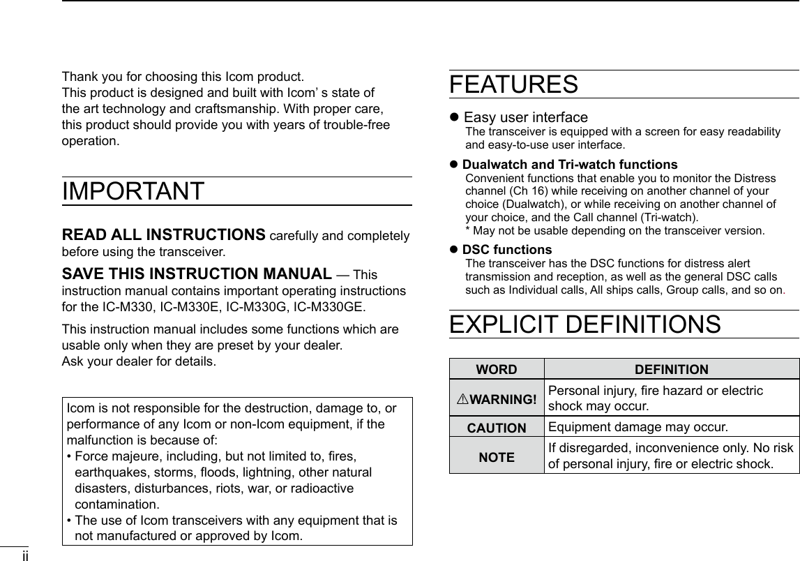
![New2001iiiIN CASE OF EMERGENCYIf your vessel requires assistance, contact other vessels and the Coast Guard by sending a distress call on Channel 16.USING CHANNEL 16DISTRESS CALL PROCEDURE1. “MAYDAY MAYDAY MAYDAY.”2. “THIS IS ...............” (name of vessel).3. Say your call sign or other indication of the vessel (AND your 9 digit DSC ID, if you have one).4. “LOCATED AT ...............” (your position).5. State the nature of the distress and assistance required.6. Give any other information which might facilitate the rescue.Or, transmit your Distress call using Digital Selective Calling (DSC) on Channel 70.USING DIGITAL SELECTIVE CALLING (Ch 70)DISTRESS CALL PROCEDURE1. While lifting up the key cover, hold down [DISTRESS] for 3 seconds until you hear 3 short beeps and then one long beep.2. Wait for an acknowledgment on Channel 70 from a coast station. • After the acknowledgement is received, Channel 16 is automatically selected.3. Hold down [PTT], then transmit the appropriate information as listed to the left.Key cover](https://usermanual.wiki/ICOM-orporated/397400/User-Guide-3625175-Page-3.png)
![New2001xiKEY ICON DESCRIPTIONThe keys are described in this manual as followings: zThe keys which have an icon on it are described with the characters “[ ]”. Example: [MENU], [CLR] zThe software keys are described with the icon such as ENT or DISTRESS. The function of the keys are shown at the bottom of the display. Push the key below the desired function. zyou can use the following keys in the Menu screen.FUNCTION ACTIONSelect Rotate [DIAL], or push [▼] or [▲].Enter Push [ENT], ENT, or [DIAL]Go to the next tree level Push [ENT], ENT, [DIAL], or [►].Go back to the previous tree level Push [CLR], BACK, or [◄].Cancel Push [CLR].Exit Push [MENU] or EXITTABLE OF CONTENTSIMPORTANT ......................................................................... iiFEATURES ........................................................................... iiEXPLICIT DEFINITIONS ...................................................... iiIN CASE OF EMERGENCY .................................................iiiRADIO OPERATION WARNING ......................................... ivAVERTISSEMENT POUR LES OPÉRATEURS RADIO ...... vFCC INFORMATION ........................................................... viNOTE ................................................................................... viPRECAUTIONS ...................................................................viiPRÉCAUTIONS ..................................................................viiiCOUNTRY CODE LIST ....................................................... ixDISPOSAL ........................................................................... ixABOUT CE AND DOC ......................................................... ixRECOMMENDATION ........................................................... xINSTALLATION NOTE .........................................................xKEY ICON DESCRIPTION .................................................. xi1. OPERATING RULES .......................................................12. PANEL DESCRIPTION .................................................... 2 ■Front Panel ..................................................................2 ■Function Display ..........................................................3 ■Software keys ..............................................................4 ■Microphone ..................................................................63. PREPARATIONS .............................................................7 ■Entering the MMSI code ..............................................7 ■Entering the ATIS ID (For Dutch and German versions) ....8](https://usermanual.wiki/ICOM-orporated/397400/User-Guide-3625175-Page-11.png)
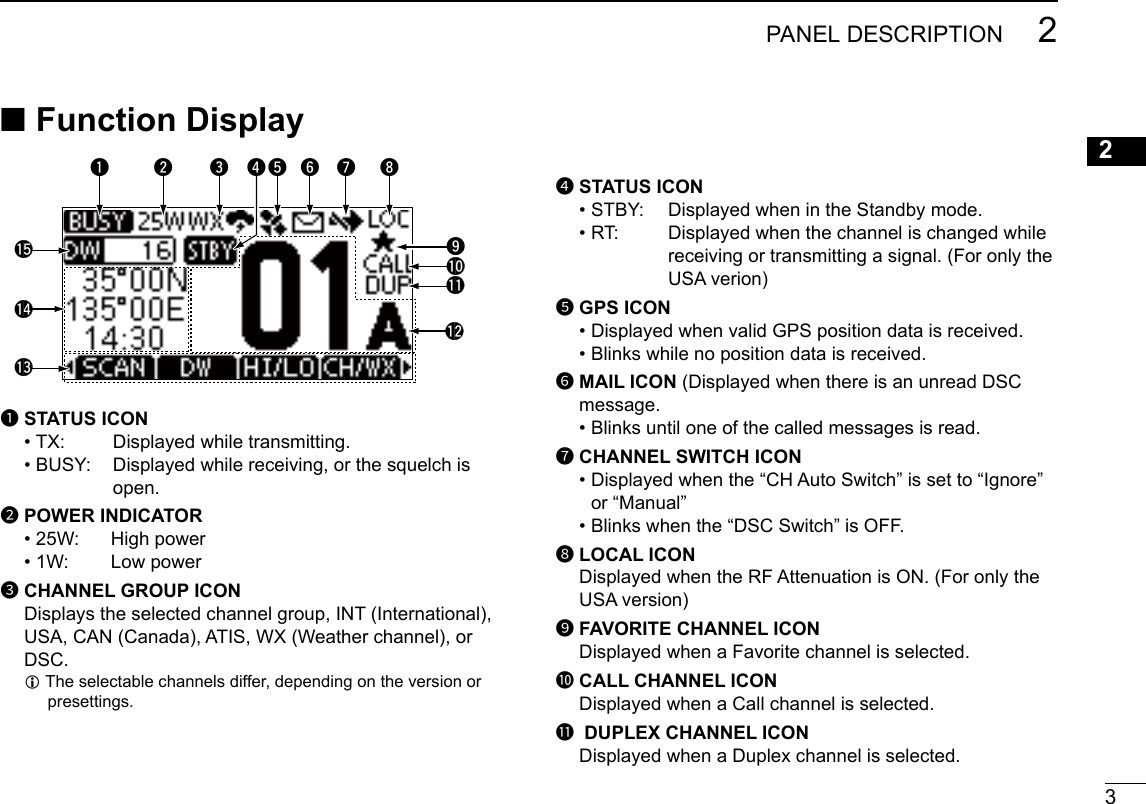
![2New20012PANEL DESCRIPTION ■Front PaneltuywioerqFunction display (p.4)Speaker1DISTRESS KEY [DISTRESS] Hold down for 3 seconds to transmit a Distress call.2ENTER KEY Push to set the entered data, selected item, and so on.3LEFT/RIGHT KEYS [◄]/[►] zPush to scroll the Software Key functions. zPush to select a character or number in the entry mode.4UP/DOWN KEYS [▲]/[▼] zPush to select an operating channel, Menu items, Menu settings, and so on. z Push to select a character or number in the entry mode.5CLEAR KEY [CLR] Push to cancel the entered data, or to return to the previous screen.6MENU KEY Push to display or close the Menu screen.7POWER/VOLUME/SQUELCH SWITCH [PWR/VOL/SQL/DIAL] zHold down for 1 second to turn the transceiver ON or OFF. zPush once to display the volume level setting screen, then rotate to adjust the volume level. zPush twice to display the squelch level setting screen, then rotate to adjust the squelch level. zRotate to select an item in the Menu screen. zPush to select a character or number, or rotate to move the cursor in the entry mode. 8CHANNEL 16/CALL CHANNEL KEY [16/C] zPush to select Channel 16. zHold down for 1 second to select the Call channel. 9SOFTWARE KEYS Scroll the key functions pushing [◄] or [►], then push either of the 4 software keys to select the function displayed at the bottom of the display. See “Software keys” on pages 4~5 for details.](https://usermanual.wiki/ICOM-orporated/397400/User-Guide-3625175-Page-14.png)
![42PANEL DESCRIPTIONNew2001 ■Software keysVarious often-used functions are assigned to the software keys for easy access. The functions’ icons are displayed above the software keys, as shown below. DUsing the software keysSelecting a software key functionPush[◄]or[►]toslidethroughtheselectablefunctionsthat are assigned to the software keys. Push the software key under the function’s icon to select the function. NOTE: The displayed icons or their order may differ, depending on the transceiver version or the presetting. Ask your dealer for details.CALL CHANNEL NUMBER Displays the selected operating channel number. LFor the USA and Canada Channels, “A” is displayed when a simplex channel is selected.SOFTWARE KEY FUNCTION DISPLAY The functions of each keys are displayed. See “Software keys” on the next page for details.POSITION/TIME REAOUTS Readouts the current position and time when valid GPS data is received, or when manually entered. • The letter after the time shows the source of the position data, I: internal, E: external, M: manual, L: local. Received GPS data: • “??” blinks if no GPS data is received for 30 seconds after receiving valid GPS data, and then “??” and a warning message are displayed alternately after 10 minutes. • A warning message is displayed if no GPS data is received for 4 hours after receiving valid GPS data. • “NO POS NO TIME” is displayed if no GPS data is received for 2 minutes after turning ON the transceiver, and then a warning message is displayed. Manually entered GPS data: • A manually entered GPS data is valid for 4 hours, and then a warning message is displayed after 4 hours.SCAN INDICATOR • “SCAN” or “SCAN 16” is displayed while scanning. • “DW” or “TW” and watched channel number is displayed while using the Dualwatch or Tri-watch function. Push [►]Push [◄]](https://usermanual.wiki/ICOM-orporated/397400/User-Guide-3625175-Page-16.png)
![5PANEL DESCRIPTION 2New200112345678910111213141516Channel/Weather channel CH/WX Push to select regular channels or Weather channels. L The Weather channel is for only the USA version. CHAN is displayed for other versions. L While the Call channel or Channel 16 is displayed, push this key to return to the regular channel mode.Low LO/DX (For only the USA version) Push to turn the Attenuator ON or OFF.AquaQuake AQUA Hold down to turn ON the AquaQuake function to clear water from the speaker grill.Favorite channel z Push to select a Favorite channel. z Hold down for 1 second to set/release the displayed channel as a Favorite channel.Channel Name NAME Push to edit the name of the displayed channel.Backlight BKLT Push to display the backlight brightness adjustment screen. LWhileintheadjustmentmode,push[▲]/[▼][◄]/[►]orrotate[DIAL] to adjust the brightness to between 1 and 7, or OFF.LOG LOG Push to display the received call log or distress message log. DSoftware keysDistress Call DISTRESS Push to display the “Distress” screen to select the nature of the call, then to make a call. LDTRS is displayed in the Multiple-task mode (for only the USA version).NEVER MAKE A DISTRESS CALL IF YOUR SHIP OR A PERSON IS NOT IN AN EMERGENCY. A DISTRESS CALL SHOULD BE MADE ONLY WHEN IMMEDIATE HELP IS NEEDED. Other DSC OTHER DSC Push to compose an Individual call, Group call, All Ships call or a Test call. LOTH is displayed in the Multiple-task mode (for only the USA version). Task TASK (For only the USA version) (p. ??)Displayed only in the Multiple-task mode. Push to display the task list. Scan SCAN Push to start or stop a Normal or Priority scan.Dualwatch/Tri-watch DW/TW Push to start or stop Dualwatch or Tri-watch.High/Low HI/LO Push to set the output power to high or low. LSome channels are set to only low power.](https://usermanual.wiki/ICOM-orporated/397400/User-Guide-3625175-Page-17.png)
![62PANEL DESCRIPTIONNew2001 ■Microphone1PTT SWITCH [PTT] Hold down to transmit, release to receive.w UP/DOWN KEYS [▲]/[▼] Push to change the channel. L When the “FAV on MIC” item is set to “ON,” you can select Favorite channels, change scanning direction or manually resume a scan.e TRANSMIT POWER KEY [HI/LO] zPush to set the power level to high or low. zSome channels are set to only low power. zWhile holding down this key, turn ON the transceiver to turn the Microphone Lock function ON or OFF. r CHANNEL 16/CALL CHANNEL KEY [16/C] zPush to select Channel 16. zHold down for 1 second to select the Call channel. • The “CALL” icon is displayed.q weMicrophoner](https://usermanual.wiki/ICOM-orporated/397400/User-Guide-3625175-Page-18.png)
![73PREPARATIONSNew200112345678910111213141516 ■Entering the MMSI codeThe Maritime Mobile Service Identity (MMSI: DSC self ID) code consists of 9 digits. You can only enter the code when turning ON the transceiver for the rst time.4. Repeat step 3 to enter all 9 digits.5. Push FIN to set the entered code. • The “Conrmation” screen is displayed.6. Enter your MMSI code again to confirm.7. Push FIN to set the entered code. • When your MMSI code is successfully entered, “MMSI Successfully Registered” is briey displayed, and then enters the operating screen. L Your MMSI code is also displayed on the operating screen.This initial code entry can be done only once.After entering, it can be changed only by your dealer or distributor. If your MMSI code has already been entered, this entry is not necessary.1. Hold down [DIAL] for 1 second to turn ON the transceiver. • Three short beeps sound, and “Push [ENT] to Register your MMSI” is displayed.2. Push [ENT] to start entering the MMSI code. • The “MMSI Input” screen is displayed. L Push [CLR] twice to skip the entry. If you skip the entry, you cannot make a DSC call. To enter the code after skipping, turn OFF the power, and then turn it ON again.3. Enter the MMSI code.NOTE: For Dutch and German versions, the ATIS ID is also required to be set. See the next page and set it.TIP: • Select a number using [◄] and [►]. • Push [ENT] to enter the selected number. • Select “←” or “→,” or rotate [DIAL] to move the cursor.](https://usermanual.wiki/ICOM-orporated/397400/User-Guide-3625175-Page-19.png)
![83PREPARATIONSNew2001The Automatic Transmitter Identication System (ATIS) ID consists of 10 digits. You can enter the ID in the “ATIS ID Input” item on the Menu screen. ■Entering the ATIS ID (For Dutch and German versions)This ID entering can be done only once. After entering, it can be changed only by your dealer or distributor. If your ATIS ID has already been entered, this entry is not necessary.1. Push [MENU]. • The Menu screen is displayed.2. Push [▲] or [▼], or rotate [DIAL] to select “ATIS ID Input,” then push [ENT] to start entering. • The “ATIS ID Input” screen is displayed.3. Enter your ATIS ID.4. Repeat step 3 to enter all 10 digits.5. Push FIN to set the entered ID. • The “Conrmation” screen is displayed.6. Enter your ATIS ID again to confirm.7. Push FIN to set the entered ID. • When your ATIS ID is successfully entered, the screen displays “ATIS ID Successfully Registered,” and then enters the operating screen. L You can check the ATIS ID in “Radio Info” on the Menu screen.TIP: • Select a number using [◄] and [►]. • Push [ENT] to enter the selected number. • Select “←” or “→,” or rotate [DIAL] to move the cursor.](https://usermanual.wiki/ICOM-orporated/397400/User-Guide-3625175-Page-20.png)
![9New2001123456789101112131415164BASIC OPERATION ■Selecting a channel DRegular ChannelYou can select a channel by pushing [▲] or [▼]. DChannel 16Channel 16 is the distress and safety channel. It is used to establish the initial contact with a station and for emergency communications. Channel 16 is monitored during both Dualwatch and Tri-watch. While in the standby mode, you must monitor Channel 16. zPush [16/C] to select Channel 16. L To return to the previously selected channel, push the software key below [CHAN] or [CH/WX]. DCall channelEach Channel Group has separate leisure-use Call channels. The Call channel is monitored during Tri-watch. The Call channels can be selected and used to store your most often used channel in each Channel Group, for quick recall. Hold down [16/C] for 1 second to select the Call channel. • The Call channel number and “CALL” are displayed. L To return to the previously selected channel, push CHAN or CH/WX.](https://usermanual.wiki/ICOM-orporated/397400/User-Guide-3625175-Page-21.png)
![104BASIC OPERATIONNew2001 DSelecting a Channel GroupChannel Groups are preset into your transceiver. You can select the Channel Group between USA, International, Canadian, DSC, and ATIS depending on the transceiver version.Version Preset Channel GroupUSA INT CAN DSC ATISUSA UK European Dutch German Chinese Australian 1. Push [MENU]. • The Menu screen is displayed.2. Push [▲], [▼] or rotate [DIAL] to select “Radio Settings,” then push [ENT]. • The “RADIO SETTINGS” screen is displayed.3. Push [▲], [▼] or rotate [DIAL] to select “Channel Group,” then push [ENT]. • The “CHANNEL GROUP” screen is displayed.4. Push [▲], [▼] or rotate [DIAL] to select a Channel Group, and then push [ENT]. Lpush EXIT to exit the Menu screen. L The selected Channel Group’s icon is displayed on the operating screen. DWeather channels and Weather AlertFor the USA an Australian versions, the transceiver has 10 preset Weather channels. You can use these channels to monitor broadcasts from the National Oceanographic and Atmospheric Administration (NOAA). The transceiver automatically detects a Weather alert tone on the selected weather channel, or while scanning.Selecting a Weather channel1. Push CH/WX. • “WX” is displayed on the operating screen instead of the Channel Group icon.2. Push [▲] or [▼] to select a Weather channel.](https://usermanual.wiki/ICOM-orporated/397400/User-Guide-3625175-Page-22.png)
![11BASIC OPERATION 4New200112345678910111213141516Setting the Weather Alert1. Push [MENU].2. Push [▲], [▼], or rotate [DIAL] to select “Radio Settings,” and then push [ENT]. • The “RADIO SETTINGS” screen is displayed.3. Select “WX Alert,” and then push [ENT]. • The “WX Alert” screen is displayed.4. Select “On W/Scan” (On with scan) or “On.” • “ ” is displayed next to the weather channel icon. ■ Adjusting the volume level zRotate [DIAL] to adjust the audio volume level. L If no key is pushed for 5 seconds, the screen automatically closes. ■ Adjusting the squelch levelSquelch enables the audio to be heard only while receiving a signal that is stronger than the set level. A higher level blocks weak signals, so that you can receive only stronger signals. A lower level enables you to hear weak signals.1. Push [VOL/SQL] twice. • The squelch level adjustment screen is displayed. 2. Rotate [DIAL] to adjust the volume level. L If no key is pushed for 5 seconds, the adjustment screen automatically closes.](https://usermanual.wiki/ICOM-orporated/397400/User-Guide-3625175-Page-23.png)
![124BASIC OPERATIONNew2001 ■Setting the Call channelBy default, a Call channel is set in each Channel Group.You can set your most often-used channel as your Call channel in each Channel Group for a quick recall. 1. Display the “CALL CHANNEL” screen. [MENU] > Radio Settings > Call Channel2. Push [▲], [▼], or rotate [DIAL] to select the channel.3. Push [ENT] to set the selected channel as the Call channel. L Push EXIT to return to the operating screen. ■ Adjusting the backlight or the display contrast1. Display the “BACKLIGHT” or “CONTRAST” screen. [MENU] > Conguration > Backlight [MENU] > Conguration > Display Contrast 2. Push [▲], [▼], or rotate [DIAL] to Adjust, then push [ENT] to set. Lpush EXIT to exit the Menu screen.](https://usermanual.wiki/ICOM-orporated/397400/User-Guide-3625175-Page-24.png)
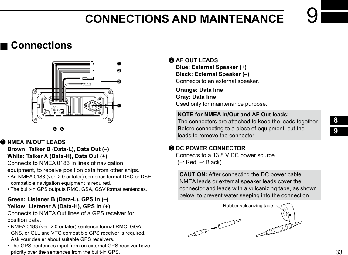
![13BASIC OPERATION 4New200112345678910111213141516 ■Receiving and transmittingCAUTION: Transmitting without an antenna may damage the transceiver.1. Push [▲] or [▼] to select the channel to call. L You cannot transmit on Channel 70. L is displayed while receiving a signal. LYou can also select the channel with [▲] or [▼] on the microphone. (only when the FAV on MIC is OFF (p. 53))2. Hold down [PTT] on the microphone and speak into the microphone. • is displayed while transmitting.3. Release [PTT] to receive.TIP: To maximize the readability of your transmitted signal, pause for a second after pushing [PTT] and hold the microphone 5 to 10 cm (2 to 4 inches) from your mouth, and then speak at your normal voice level.NOTE: • Except for the Export version, the Time-out Timer function cuts OFF transmission after 5 minutes of continuously transmitting, to prevent prolonged transmission. • The Noise Cancel function reduces random noise components in the transmit and/or received signal. ■Microphone Lock functionThe Lock function electronically locks all keys [▲], [▼], [16/C], and [H/L] on the microphone to prevent accidental channel changes or functions access.While holding down [HI/LO] on the microphone, hold down [PWR] (Dial) for 1 second to turn the Lock function ON or OFF.Hold down to transmit.Release to receive.Select a channel. Speak to the Microphone[16/C][▲]/[▼] [HI/LO]](https://usermanual.wiki/ICOM-orporated/397400/User-Guide-3625175-Page-25.png)
![144BASIC OPERATIONNew2001 ■Editing a channel nameYou can edit the name of each operating channel and weather channel, using numbers, uppercase letters, symbols, and a space. This enables easy recognition of the channels or stations. All VHF marine channels are set with default names.1. Push [▲] or [▼] to select the channel to edit.2. Push [◄] or [►] to select NAME. L You cannot edit a channel name during Dualwatch, Tri-watch, or a Scan.3. Push NAME. • The “Channel Name” screen is displayed.4. Edit the channel name. TIP: • Select !$? to enter characters, and select 123 to enter numbers and letters. • Select characters or space using [▲]/[▼]/[◄]/[►]. • Push [ENT] to enter the selected character. • Select “←” or “→,” or rotate [DIAL] to move the cursor. • Push EXIT to cancel editing.5. Push [FIN] to set the edited name. ■ AquaQuake Water Draining functionWater in the speaker grill may mufe the sound coming from the speaker. The AquaQuake Water Draining function removes water from the speaker grill by vibrating the speaker.1. Push [◄] or [►] to select AQUA.2. Hold down AQUA to turn ON the function. • A low frequency vibration beep sounds to drain the water, regardless of the volume level setting. L This function is activated for a maximum of 10 seconds, even if you continue to hold down AQUA.3. Release the key to turn OFF the function.](https://usermanual.wiki/ICOM-orporated/397400/User-Guide-3625175-Page-26.png)
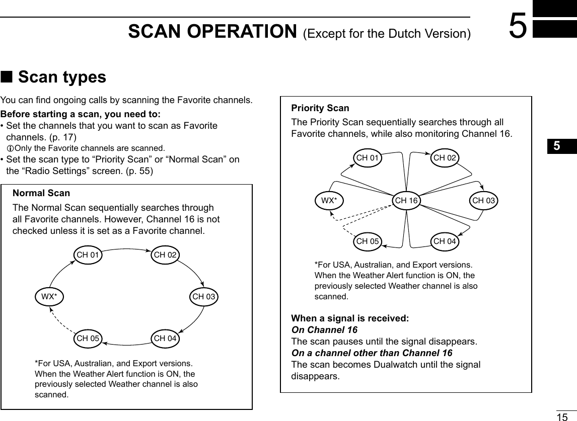
![New2001165SCAN OPERATION (Except for the Dutch Version)New2001 ■Starting a scan1. Select a Channel Group.2. Push [◄] or [►] to display SCAN.3. Push SCAN. • The scan starts. • “ ” is displayed during a Priority Scan, and “ ” is displayed during a Normal Scan. L When a signal is received, the scan pauses until the signal disappears, or resumes after 5 seconds, depending on the Scan Timer setting in “Radio Settings.” L A beep sounds and “16” blinks when a signal is received on Channel 16 during a Priority scan.4. To stop the scan, push SCAN. ■Setting Favorite channelsYou can quickly recall often-used channels by setting them as Favorite channels. You can set Favorite channels in each Channel Group.1. Select a Channel Group.2. Push [▲] or [▼] to select the channel you want to set as a Favorite channel.3. Push [◄] or [►] to display .4. Hold down for 1 second. • The selected channel is set as a Favorite channel, and “ ” is displayed. LTo cancel the setting, again for 1 second.TIP: You can set all channels as Favorite channels, clear all settings, or reset to the default. By default, some channels are preset as Favorite channels. The preset channels differ, depending on the transceiver version.TIP: In order to properly receive signals, be sure to adjust the squelch to a suitable level.Example: Starting a Normal ScanPush to startWhen a signal is received“ ” and “ ” are displayed. While scanning“” is displayed.](https://usermanual.wiki/ICOM-orporated/397400/User-Guide-3625175-Page-28.png)
![17New2001123456789101112131415166DUALWATCH/TRI-WATCH (Except for the Dutch Version) ■DescriptionDualwatch and Tri-watch are convenient to monitor Channel 16 while you are operating on another channel.When a signal is received:On Channel 16Dualwatch/Tri-watch pauses on Channel 16 until the signal disappears.On the Call channelTri-watch switches to Dualwatch until the signal on the Call channel disappears.Ch 88Ch 16Ch 88Ch 16Ch 9Normal channelCall channelNormal channelMonitors Channel 16 while receiving on another channel.Monitors Channel 16 and the Call channel while receiving on another channel.Dualwatch Tri-watch ■Operation1. Select Dualwatch or Tri-watch in “Radio Settings” in the Menu screen.2. Push [▲] or [▼] to select a channel.3. Push [◄] or [►] to display DW (Dualwatch) or TW (Tri-watch).4. Push DW or TW. • Dualwatch or Tri-watch starts. • “ ” is displayed for Dualwatch, and “ ” is displayed for Tri-watch. LBeeps sound when a signal is received on Channel 16.5. To cancel Dualwatch or Tri-watch, push DW or TW again.Example: Operating Tri-watch on INT Channel 25.Push to startSignal is received on the Call channel.“ ” is displayed.Signal received on Channel 16 takes priority. “16” blinks. LTri-watch resumes after the signal disappears.](https://usermanual.wiki/ICOM-orporated/397400/User-Guide-3625175-Page-29.png)
![18New20017DSC OPERATION ■DSC address ID DEntering an Individual IDYou can enter a total of 60 Individual IDs, and assign names of up to 10 characters.1. Display the “INDIVIDUAL ID” screen. [MENU] > DSC Settings > Individual ID • “No ID” is displayed if no ID is entered.2. Push ADD. • “The Individual ID” entry screen is displayed.3. Enter the Individual ID.TIP: • Selectanumberusing[◄]and[►]. • Push [ENT] to enter the selected number. • Select“←”or“→,”orrotate[DIAL]tomovethecursor.NOTE:therstdigitisxedas“0”foraGroupID.Thersttwodigitsarexedas“0”foranyCoaststation ID.4. Push FIN to start entering the name. TIP: • Push !$? to use characters, and select ABC to use numbers and letters. • Selectcharactersorspaceusing[▲]/[▼]/[◄]/[►]. • Select“◄”or“►”toscroll. • Push [ENT] to enter the selected character. • Select“←”or“→,”orrotate[DIAL]tomovethecursor.5. After entering, push FIN to save, and return to the previous screen. • The entered name is displayed.](https://usermanual.wiki/ICOM-orporated/397400/User-Guide-3625175-Page-30.png)
![19DSC OPERATION 7New200112345678910111213141516New2001 DEntering a Group IDYoucanenteratotalof30GroupIDs,andassignnamesofup to 10 characters.1. Displaythe“GROUPID”screen. [MENU] > DSC Settings > Group ID • “No ID” is displayed if no ID is entered.2. Push ADD. • TheGroupID’sentryscreenisdisplayed.3. EntertheGroupIDanditsnameinthesamewayasdescribed on the previous page.4. After entering, push FIN to save, and return to the previous screen. • The entered name is displayed.NOTE:Therstdigitisxedas“0”foraGroupID.Thersttwodigitsarexedas“0”foranyCoaststation ID. DDeleting an entered ID(Example:DeletinganIndividualID:ICOM2)1. Display the “INDIVIDUAL ID” screen. [MENU] > DSC Settings > Individual ID2. Push[▲]or[▼]toselect“ICOM2.”3. Push DEL. • “Are You Sure?” is displayed.4. Push OK to delete. L Push CANCEL to cancel the deletion. • The selected ID is deleted, and then returns to the previous screen.TIP:YoucaneditanIDanditsnamebypushingEDIT in step 3.](https://usermanual.wiki/ICOM-orporated/397400/User-Guide-3625175-Page-31.png)
![207DSC OPERATIONNew2001 ■Entering the position and timeADistresscallshouldincludethevessel’spositionandtime.IfnoGPSdataisreceived,manuallyenterthepositionandUniversalTimeCoordinated(UTC)time.NOTE: • ThemanualentryisdisabledwhiletheGPSdataisreceived. • The manually entered position and time is valid only for 4 hours, or until turning OFF the transceiver.1. Display the “POSITION INPUT” screen. [MENU] > DSC Settings > Position Input2. Enter the latitude.TIP: • Selectanumberoracompassdirectionusing[▲]/[▼]/[◄]/[►]. • Select“←”or“→,”orrotate[DIAL]tomovethecursor. • Push [ENT] or FIN to enter the selected number. 3. Enter the longitude and the UTC time. LSee the TIP in step 2 to enter. 4. Push FIN to set the entered position and time.5. Push EXIT to return to the standby screen. L The entered position and time are displayed on the operating screen. L“M”(manual)isdisplayednexttothetimedisplay.](https://usermanual.wiki/ICOM-orporated/397400/User-Guide-3625175-Page-32.png)
![21DSC OPERATION 7New200112345678910111213141516 ■Sending DSC calls (Distress)A Distress call should be sent if, in the opinion of the Master, the ship or a person is in distress and requires immediate assistance.NEVER MAKE A DISTRESS CALL IF YOUR SHIP OR A PERSON IS NOT IN AN EMERGENCY. A DISTRESS CALL SHOULD BE MADE ONLY WHEN IMMEDIATE HELP IS NEEDED. DSimple call1. Confirm that no Distress call is being received.2. Whileliftingupthekeycover,holddown[DISTRESS]for3secondsuntilyouhear3shortcountdownbeepsand a long beep sound. • The backlight blinks.3. Aftersending,waitforanAcknowledgementcall. • “Waiting for ACK” is displayed. L The Distress call is automatically sent every 3.5 to 4.5 minutes,untilanAcknowledgementisreceived,oraDistress Cancel call is sent. LWhenyoureceiveanAcknowledgement,alarmsounds.4. PushanysoftwarekeytoturnOFFthealarm. • Channel 16 is automatically selected.5. Holddown[PTT]toexplainyoursituation.6. Push CANCEL to return to the operating screen.TIP:AdefaultDistressalertcontains: • Natureofdistress:Undesignateddistress • Positioninformation:ThelatestGPS,ormanuallyinputposition,whichisheldfor23.5hoursoruntilturningOFFthe transceiver.NOTE on Distress calls (Simple calls and Regular calls): IfnovalidpositiondataisreceivedwhensendingaDistress call, thetransceiverwaitsfor15secondsuntilposition data is received, and then the Distress call is sent. If no position is received during this 15 seconds, the position data in the transceiver memory is automatically sent.However,ifthereisnopositiondatainthememory,theDistresscallissentwithoutpositiondata.Key cover](https://usermanual.wiki/ICOM-orporated/397400/User-Guide-3625175-Page-33.png)
![227DSC OPERATIONNew2001 DRegular callSelect the nature of the Distress call to include in the Regular Distress call.1. Push DISTRESS. • The Distress Call screen is displayed.2. Push [ENT] to enter the Nature selection mode.3. Push[▲],[▼],orrotate[DIAL]toselectthenatureofthecall,thenpush[ENT].(Example:Flooding) • Theconrmationscreenisdisplayed. LIfnovalidGPSdataisbeingreceived,push[▲],[▼],orrotate [DIAL] to select “Position,” then enter the latitude, longitude, and UTC. L See “Entering the position and time” for details.”4. Whileliftingupthekeycover,holddown[DISTRESS](theredbutton)for3secondsuntilyouhear3shortcountdownbeepsandalongbeepsound. • The backlight blinks.5. Aftersending,waitforanAcknowledgementcall. • “Waiting for ACK” is displayed. L The Distress call is automatically sent every 3.5 to 4.5 minutes,untilanAcknowledgementisreceived,oraDistress Cancel call is sent. LWhenanAcknowledgementisreceived,analarmsounds.6. PushanysoftwarekeytoturnOFFthealarm. • Channel 16 is automatically selected.7. Holddown[PTT]tocommunicate.TIP:YoucanalsosendaRegularcallbyselectingthe“Compose Distress” item on the Menu screen.](https://usermanual.wiki/ICOM-orporated/397400/User-Guide-3625175-Page-34.png)
![23DSC OPERATION 7New200112345678910111213141516 DDistress Cancel callIf you have accidently made a Distress call, or made an incorrect Distress call, send a Distress Cancel call to cancelthecallassoonaspossiblewhilewaitingforanAcknowledgementcall,andreportthepurposeofthecancellation.1. WhilewaitingforanAcknowledgementcall,pushCANCEL. • Thescreenbelowisdisplayed.2. Push CONTINUE. • The Distress Cancel call is sent. • Channel 16 is automatically selected.3. Holddown[PTT]toreportthepurposeofthecancellation. LYoucandisplaythewordingofthecancellationbypushing[▼].4. After communicating, push FINISH. • The screen to the right is displayed.5. Push OK to finish the Distress Cancel call. • Returns to the operating screen. DDistress call software key descriptionWhile waiting for an Acknowledgement:[CANCEL]: Cancels the Distress call and enables you to sendaCancelcall.(Seetherightcolumn)[RESEND]: Enables you to resend the Distress call by holdingdown[DISTRESS]again.[PAUSE]: PausesthecountdowntoresendthenextDistress call.[INFO]: Displays the information of the Distress call that you have sent.After receiving an Acknowledgement:[EXIT]: Closes the Distress operation, and returns to the operating screen.[HIST]: Displays the “Distress History.”[INFO]: Displays the information of the received DistressAcknowledgement.NOTE (For USA and Export versions):After sending a Distress call without position data • WhilewaitingforanAcknowledgement,ifvalidpositiondataisreceived,thetransceiverwillautomaticallysendaDistresscallagain. • EvenafterexitingtheDSCmode,ifvalidpositiondataisreceivedwithin20minutesafterreceivingaDistressAcknowledgement,thetransceiverwillautomaticallysendaDistress call again.](https://usermanual.wiki/ICOM-orporated/397400/User-Guide-3625175-Page-35.png)
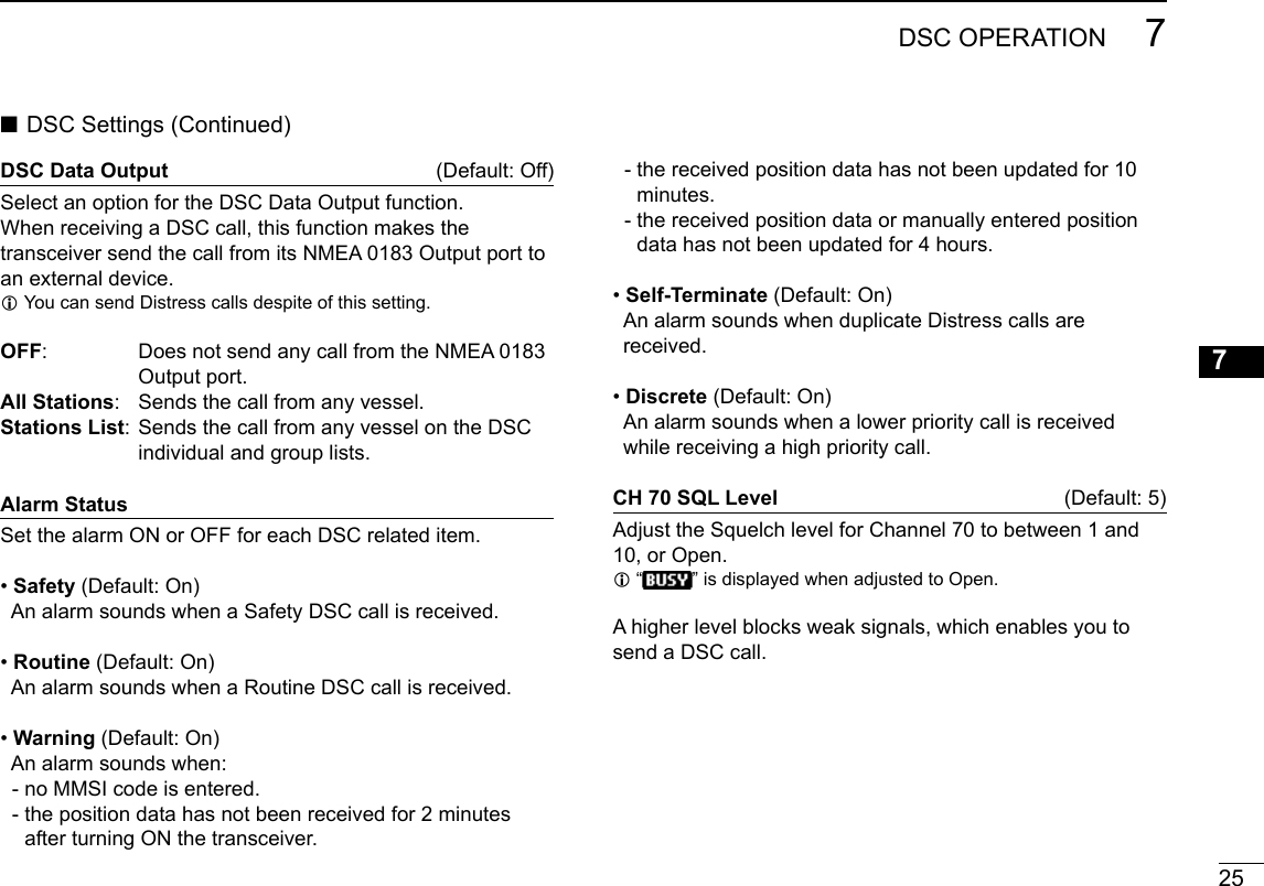
![247DSC OPERATIONNew2001 ■DSC SettingsOn the “DSC Settings” screen, you can make settings on the DSC call related items. Position InputSee “Entering the position and time” for details.Individual IDSee “Entering an Individual ID” for details.Group IDSee “Entering a Group ID” for details.Auto ACKThe Auto ACK function automatically sends an Acknowledgementcallwhenthefollowingcallsarereceived. • Individualcall(Default:Differsdependingontheversion) • PositionRequestcall(Default:Manual) • PollingRequestcall(Default:Auto) • Testcall(Default:Auto)Manual:ManuallysendanAcknowledgementcall.Auto: AutomaticallysendanAcknowledgementcall.CH Auto Switch (Default:Accept)Selectwhetherornottoautomaticallyswitchtochannel16orthespeciedchannel,orselectwhethertoswitchorignore the call.Accept:AfterreceivingaDSCcall,thetransceiverremainson the operating channel for 10 seconds. After that,thetransceiverautomaticallyswitchestothechannelthatisspeciedontheDSCcall.Ignore: AfterreceivingaDSCcall,ifyoudonotpushthesoftwarekeybelow[ACPT]in10seconds,thetransceiver ignores the call, and then remains on the current operating channel.Manual:AfterreceivingaDSCcall,youcanselectwhetheror not to accept the received DSC call.TIP: When “Auto” is set to the Individual call, the Acknowledgement“UnabletoComply”isautomaticallysentwhenthe call is received.](https://usermanual.wiki/ICOM-orporated/397400/User-Guide-3625175-Page-36.png)
![267DSC OPERATIONNew2001Self- TestThe Self-Test sends DSC signals to the receiving AF circuit to compare the sending and receiving signals at the AF level. zPush [ENT] to start the Self Test. L When the sending and receiving DSC signals match, “OK” is displayed.Procedure (Default:Single)(ForonlytheUSAversion,dependingonthepresetting.)You can select the type of task for the transceiver.Single: Handlesonly1taskatthesametime.Multiple: Handlesupto7tasksatthesametime.Youcanmake one or more than 2 DSC calls in parallel.](https://usermanual.wiki/ICOM-orporated/397400/User-Guide-3625175-Page-38.png)
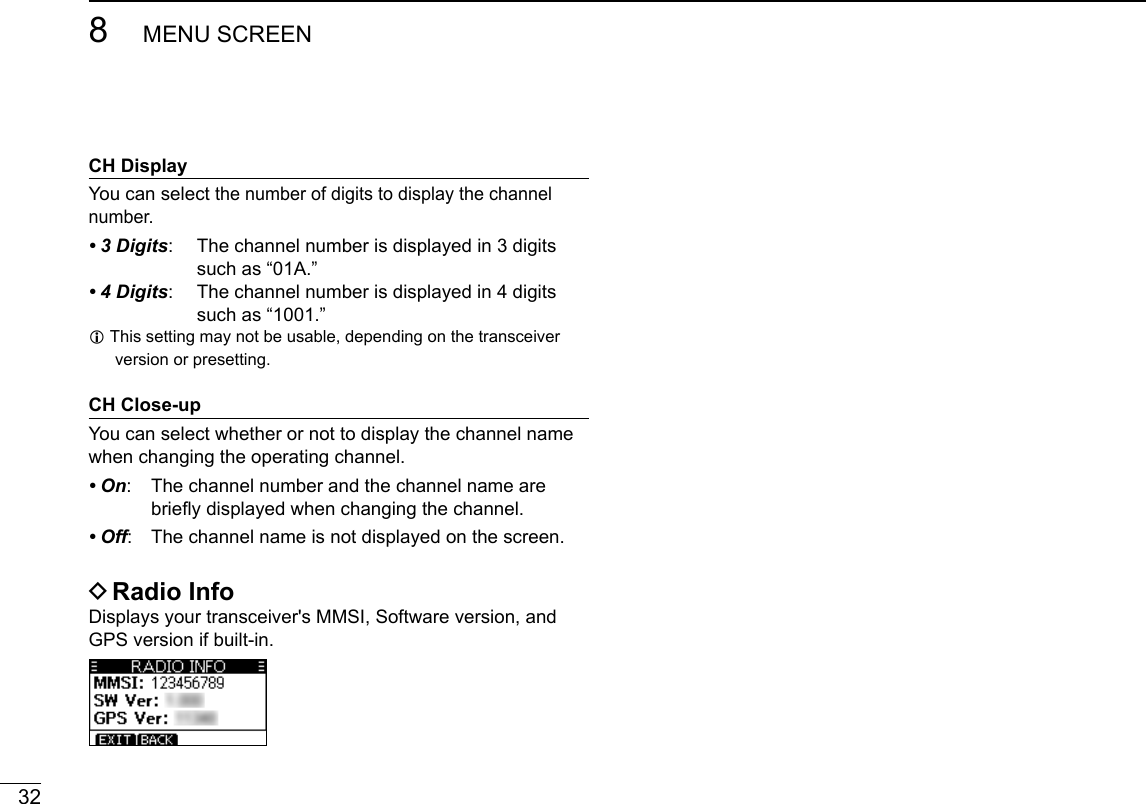
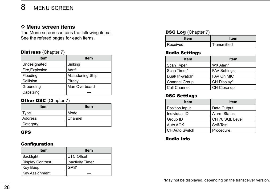
![27New2001123456789101112131415168MENU SCREEN ■Using the Menu screenThe Menu screen is used to set items, select options, and so on for the transceiver’s functions. DUsing the Menu screenExample: Setting the channel group to “INT.”1. Push [MENU]. • The Menu screen is displayed.2. Push[▲],[▼],orrotate[DIAL]toselect“RadioSettings,” and then push [ENT]. • The“RadioSettings”screenisdisplayed. LHoldingdown[▲]or[▼]sequentiallyscrollsupordownthroughthe Menu screen.3. Push[▲],[▼],orrotate[DIAL]toselect“ChannelGroup,” then push [ENT]. • The“CHANNELGROUP”screenisdisplayed.4. Push[▲],[▼],orrotate[DIAL]toselect“INT,”thenpush [ENT]. L “INT” is set and the transceiver returns to the previous screen.TIP: L To exit the Menu screen, push EXIT or [MENU]. L To return to the previous screen, push BACKor[CLR].](https://usermanual.wiki/ICOM-orporated/397400/User-Guide-3625175-Page-39.png)
![31MENUSCREEN 8New200112345678910111213141516ChannelGroupSelect the suitable channel group for your operating area. SelectINT,USA,CAN,DSC,orATISdependingonthetransceiver version.CallChancelYoucanchangeyourCallchannel.Thedefaultsettingdiffers, depending on the transceiver version.WXAlert (Default:Off)FortheUSAandAustralianversions,anNOAAbroadcaststationtransmitsaWeatherAlerttonebeforeanyimportantweather information. L“WX ” is displayed instead of “WX.” L “WX ” blinks until you push a key after detecting an alert.• On W/ SC: The preset Weather channels are sequentiallycheckedwhilescanning.• On: Thepreviouslyselected(lastused)Weatherchannel is checked while scanning.• Off: TheWeatherAlerttoneisnotdetected.FAVSettingsYou can set all channels as Favorite channels, clear all settings, or reset to default. By default, some channels are preset. The Favorite channels differ, depending on the transceiver version.• Set All Channels: Sets all channels as Favorite channels.• Clear All Channels:ClearsallFavoritechannels.• Set Default: ResetsFavoritechannelstothedefault.FAVonMIC (Default:Off)Youcanselectthechannelsetwhenyoupush[▲]or[▼]onthe supplied microphone.• On: Scrolls through only the Favorite channels.• Off: Scrolls through all the channels.](https://usermanual.wiki/ICOM-orporated/397400/User-Guide-3625175-Page-43.png)