ICOM orporated 397400 VHF Marine Transceiver User Manual
ICOM Incorporated VHF Marine Transceiver
User manual

VHF MARINE TRANSCEIVER
iM330
iM330E
iM330G
iM330GE
INSTRUCTION MANUAL
INSTRUCTION MANUAL
1-1-32 Kamiminami, Hirano-ku, Osaka 547-0003, Japan
This device complies with Part 15 of the FCC rules. Operation
is subject to the condition that this device does not cause
harmful interference.
Picture In Progress

New2001
ii
Thank you for choosing this Icom product.
This product is designed and built with Icom’ s state of
the art technology and craftsmanship. With proper care,
this product should provide you with years of trouble-free
operation.
IMPORTANT
READ ALL INSTRUCTIONS carefully and completely
before using the transceiver.
SAVE THIS INSTRUCTION MANUAL — This
instruction manual contains important operating instructions
for the IC-M330, IC-M330E, IC-M330G, IC-M330GE.
This instruction manual includes some functions which are
usable only when they are preset by your dealer.
Ask your dealer for details.
EXPLICIT DEFINITIONS
WORD DEFINITION
RWARNING! Personal injury, re hazard or electric
shock may occur.
CAUTION Equipment damage may occur.
NOTE If disregarded, inconvenience only. No risk
of personal injury, re or electric shock.
Icom is not responsible for the destruction, damage to, or
performance of any Icom or non-Icom equipment, if the
malfunction is because of:
• Force majeure, including, but not limited to, res,
earthquakes, storms, oods, lightning, other natural
disasters, disturbances, riots, war, or radioactive
contamination.
• The use of Icom transceivers with any equipment that is
not manufactured or approved by Icom.
FEATURES
zEasy user interface
The transceiver is equipped with a screen for easy readability
and easy-to-use user interface.
zDualwatch and Tri-watch functions
Convenient functions that enable you to monitor the Distress
channel (Ch 16) while receiving on another channel of your
choice (Dualwatch), or while receiving on another channel of
your choice, and the Call channel (Tri-watch).
* May not be usable depending on the transceiver version.
zDSC functions
The transceiver has the DSC functions for distress alert
transmission and reception, as well as the general DSC calls
such as Individual calls, All ships calls, Group calls, and so on.
New2001
iii
IN CASE OF EMERGENCY
If your vessel requires assistance, contact other vessels and
the Coast Guard by sending a distress call on Channel 16.
USING CHANNEL 16
DISTRESS CALL PROCEDURE
1. “MAYDAY MAYDAY MAYDAY.”
2. “THIS IS ...............” (name of vessel).
3. Say your call sign or other indication of the vessel
(AND your 9 digit DSC ID, if you have one).
4. “LOCATED AT ...............” (your position).
5. State the nature of the distress and assistance
required.
6. Give any other information which might facilitate
the rescue.
Or, transmit your Distress call using Digital Selective Calling
(DSC) on Channel 70.
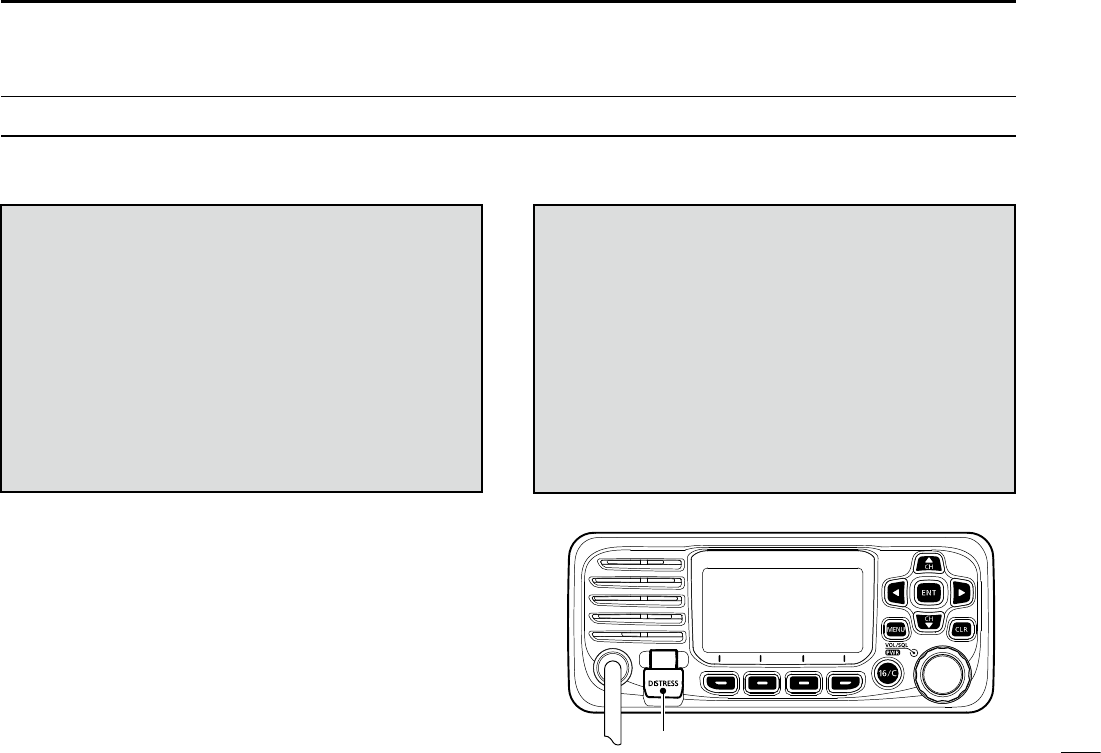
USING DIGITAL SELECTIVE CALLING (Ch 70)
DISTRESS CALL PROCEDURE
1. While lifting up the key cover, hold down
[DISTRESS] for 3 seconds until you hear 3 short
beeps and then one long beep.
2. Wait for an acknowledgment on Channel 70
from a coast station.
• After the acknowledgement is received, Channel 16
is automatically selected.
3. Hold down [PTT], then transmit the appropriate
information as listed to the left.
Key cover

New2001
iv
RADIO OPERATION WARNING
WARNING
Icom requires the radio operator to meet the
FCC Requirements for Radio Frequency
Exposure. An omnidirectional antenna with
gain not greater than 9 dBi must be mounted a
minimum of 5 meters (measured from the
lowest point of the antenna) vertically above
the main deck and all possible personnel. This is the
minimum safe separation distance estimated to meet all RF
exposure compliance requirements. This 5 meter distance is
based on the FCC Safe Maximum Permissible Exposure
(MPE) distance of 3 meters added to the height of an adult
(2 meters) and is appropriate for all vessels.
For watercraft without suitable structures, the antenna must be
mounted so as to maintain a minimum of 1 meter vertically between
the antenna, (measured from the lowest point of the antenna), to
the heads of all persons AND all persons must stay outside of the 3
meter MPE radius.
Do not transmit with radio and antenna when persons are within the
MPE radius of the antenna, unless such persons (such as driver
or radio operator) are shielded from antenna eld by a grounded
metallic barrier. The MPE Radius is the minimum distance from
the antenna axis that person should maintain in order to avoid RF
exposure higher than the allowable MPE level set by FCC.
FAILURE TO OBSERVE THESE LIMITS MAY ALLOW
THOSE WITHIN THE MPE RADIUS TO EXPERIENCE RF
RADIATION ABSORPTION WHICH EXCEEDS THE FCC
MAXIMUM PERMISSIBLE EXPOSURE (MPE) LIMIT.
IT IS THE RESPONSIBILITY OF THE RADIO OPERATOR
TO ENSURE THAT THE MAXIMUM PERMISSIBLE
EXPOSURE LIMITS ARE OBSERVED AT ALL TIMES
DURING RADIO TRANSMISSION. THE RADIO
OPERATOR IS TO ENSURE THAT NO BYSTANDERS
COME WITHIN THE RADIUS OF THE MAXIMUM
PERMISSIBLE EXPOSURE LIMITS.
Determining MPE Radius
THE MAXIMUM PERMISSIBLE EXPOSURE (MPE)
RADIUS HAS BEEN ESTIMATED TO BE A RADIUS OF
ABOUT 3M PER OET BULLETIN 65 OF THE FCC.
THIS ESTIMATE IS MADE ASSUMING THE MAXIMUM
POWER OF THE RADIO AND ANTENNAS WITH A
MAXIMUM GAIN OF 9dBi ARE USED FOR A SHIP
MOUNTED SYSTEM.

New2001
v
AVERTISSEMENT POUR LES OPÉRATEURS RADIO
Icom exige que l'opérateur radio se conforme aux
exigences de la FCC en matière d'exposition aux
radiofréquences. Une antenne omnidirectionnelle
dont le gain ne dépasse pas 9dBi doit être xée
à une distance minimale de 5 mètres (mesurée
depuis le point le plus bas de l'antenne)
verticalement au-dessus du pont principal et de tout le personnel
qui peut s'y trouver. Il s'agit de la distance de sécurité minimale
prévue pour satisfaire aux exigences de conformité en matière
d'exposition aux RF. Cette distance de 5 mètres est établie en
fonction de l'exposition maximale admissible sécuritaire de 3 mètres
établie par la FCC, à laquelle on ajoute la hauteur d'un adulte (2
mètres); cette distance convient pour tous les navires.
Dans le cas des embarcations sans structure convenable, l'antenne
doit être xée de façon à maintenir une distance minimale de 1
mètre verticalement entre cette antenne (mesurée depuis son
point le plus bas) et la tête de toute personne présente; toutes
les personnes présentes doivent se tenir à l'extérieur d'un rayon
d'exposition maximale admissible de 3 mètres.
Ne pas émettre à l'aide de la radio et de l'antenne lorsque des
personnes se trouvent à l'intérieur du rayon d'exposition maximale
admissible de cette antenne, à moins que ces personnes (comme
le conducteur ou l'opérateur radio) ne soient protégées du champ
de l'antenne par un écran métallique relié à la masse. Le rayon
d'exposition maximale admissible équivaut à la distance minimale
que cette personne doit maintenir entre elle et l'axe de l'antenne
pour éviter une exposition aux RF supérieure au niveau d'exposition
maximale admissible xé par la FCC.
LE NON-RESPECT DE CES LIMITES PEUT CAUSER,
POUR LES PERSONNES SITUÉES DANS LE RAYON
D'EXPOSITION MAXIMALE ADMISSIBLE, UNE ABSORPTION
DE RAYONNEMENT DE RF SUPÉRIEURE À L'EXPOSITION
MAXIMALE ADMISSIBLE FIXÉE PAR LA FCC.
L'OPÉRATEUR RADIO EST RESPONSABLE D'ASSURER QUE
LES LIMITES D'EXPOSITION MAXIMALE ADMISSIBLE SOIENT
RESPECTÉES EN TOUT TEMPS PENDANT LA TRANSMISSION
RADIO. L'OPÉRATEUR RADIO DOIT S'ASSURER QU'AUCUNE
PERSONNE PRÉSENTE NE SE SITUE À L'INTÉRIEUR DU
RAYON D'EXPOSITION MAXIMALE ADMISSIBLE.
Établir le rayon d'exposition maximale admissible
ON ESTIME QUE LE RAYON D'EXPOSITION MAXIMALE
ADMISSIBLE EST D'ENVIRON 3 M, TEL QUE STIPULÉ DANS
LE BULLETIN OET 65 DE LA FCC. CETTE DISTANCE ESTIMÉE
TIENT COMPTE D'UN SYSTÈME INSTALLÉ SUR UN NAVIRE
UTILISANT LA PUISSANCE MAXIMALE DE LA RADIO ET DES
ANTENNES DONT LE GAIN MAXIMAL EST DE 9dBi.
AVERTISSEMENT
New2001
vi
FCC INFORMATION
This equipment has been tested and found to comply with
the limits for a Class A digital device, pursuant to part 15
of the FCC Rules. These limits are designed to provide
reasonable protection against harmful interference when the
equipment is operated in a commercial environment. This
equipment generates, uses, and can radiate radio frequency
energy and, if not installed and used in accordance with the
instruction manual, may cause harmful interference to radio
communications.
Operation of this equipment in a residential area is likely to
cause harmful interference in which case the user will be
required to correct the interference at his own expense.
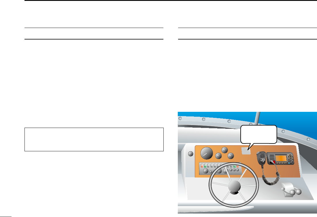
NOTE
A WARNING STICKER is supplied with the USA
version transceiver.
To comply with FCC regulations, this sticker must be
afxed in such a location as to be readily seen from the
operating controls of the radio as in the diagram below.
Make sure the chosen location is clean and dry before
applying the sticker.
EXAMPLE
WARNING.
WARNING
STICKER
CAUTION: Changes or modications to this device, not
expressly approved by Icom Inc., could void your authority
to operate this device under FCC regulations.

New2001
vii
PRECAUTIONS
RWARNING! NEVER
connect the transceiver directly to an AC
outlet. This may cause a re or an electric shock.
RWARNING! NEVER connect the transceiver to a power
source of more than 16 V DC such as a 24 V battery. This
connection could cause a re or damage the transceiver.
RWARNING! NEVER reverse the DC power cable polarity
when connecting to a power source. This could damage the
transceiver.
RWARNING! NEVER cut the DC power cable between the
DC plug at the back of the transceiver and the fuse holder. If
an incorrect connection is made after cutting, the transceiver
may be damaged.
RWARNING! NEVER operate the transceiver during a
lightning storm. It may result in an electric shock, cause a
re or damage the transceiver. Always disconnect the power
source and antenna before a storm.
RWARNING!
NEVER
place the transceiver where normal
operation of the vessel may be hindered, or where it could
cause bodily injury.
CAUTION: KEEP the transceiver and microphone at least 1
meter away from the vessel’s magnetic navigation compass.
CAUTION: DO NOT place or leave the transceiver in areas
with temperatures below –20°C ~ +60°C (–4ºF ~ +140ºF), or
in areas subject to direct sunlight, such as a dashboard.
CAUTION: DO NOT use harsh solvents such as Benzine
or alcohol to clean the transceiver, as they will damage the
transceiver’s surfaces. If the transceiver becomes dusty or
dirty, wipe it clean with a soft, dry cloth.
BE CAREFUL! The transceiver rear panel will become hot
when transmitting continuously for long periods of time.
Place the transceiver in a secure place to avoid inadvertent
use by unauthorized persons.
BE CAREFUL! The transceiver’s front panel meets IPX7
requirements for waterproof protection*. However, once
the transceiver or microphone has been dropped, or
the waterproof seal is cracked or damaged, waterproof
protection cannot be guaranteed because of possible
damage to the case or the waterproof seal.
* Except for the DC power connector, NMEA In/Out leads and AF
Out leads.

New2001
viii
PRÉCAUTIONS
RAVERTISSEMENT ! NE JAMAIS relier l'émetteur-récepteur à
une prise CA. Cela pourrait provoquer un choc électrique ou un
incendie.
RAVERTISSEMENT ! NE JAMAIS brancher l'émetteur-récepteur
sur une source d'alimentation supérieure à 16 V CC, comme une
batterie de 24 V. Cela pourrait endommager l'émetteur-récepteur.
RAVERTISSEMENT ! NE JAMAIS inverser la polarité du câble
d'alimentation CC lors de la connexion à une source d'alimentation.
Cela pourrait endommager l'émetteur-récepteur.
RAVERTISSEMENT ! NE JAMAIS couper le câble d'alimentation
CC entre la prise CC a l’arrière de l’émetteur-récepteur et le porte-
fusible. L’émetteur-récepteur peut être endommagé par la suite en
cas de connexion inappropriée.
RAVERTISSEMENT ! NE JAMAIS utiliser l'émetteur-récepteur
durant un orage. Cela risquerait de provoquer un choc électrique,
un incendie ou d'endommager l'émetteur-récepteur. Toujours
débrancher la source d'alimentation et l'antenne avant une tempête.
MISE EN GARDE : NE JAMAIS installer l’émetteur-récepteur à
un emplacement où il pourrait gêner le fonctionnement normal du
navire ou provoquer des blessures corporelles.
INSTALLER la VHF et le microphone à au moins 1 m du compas
de route du navire.
NE PAS utiliser ou placer l’émetteur-récepteur dans des zones où
la temperature est inférieure à –15° ou supérieure à +55° ou dans
des zones soumises au rayonnement solaire direct, telles le tableau
de bord.
NE PAS nettoyer l'appareil avec des solvants agressifs tels que
benzène ou alcool, susceptibles d'endommager les surfaces
exposées du boitier. En cas de dépôt de poussière ou de salissures
sur l'émetteur-récepteur, il faut l'essuyer avec chiffon doux et sec.
MISE EN GARDE ! La face arrière de la VHF chauffe en cas
d’utilisation continue sur une longue durée.
Placer l’émetteur-récepteur hors de portée des enfants pour éviter
toute utilisation inopinée.
MISE EN GARDE ! La face avant de l'émetteur-récepteur est
étanche conformément à la norme IPX7*. L’étanchéité ne peut plus
être garantie après une chute de l’appareil en raison des risques de
ssures du boîtier, de dégradation du joint d’étanchéité, etc.
*Les connecteurs sur le panneau arrière ne sont pas étanche IPX7.
Si la face avant est exposée à de l'eau de mer, ASSUREZ-VOUS
DE LE NETTOYER ENTIEREMENT AVEC DE L'EAU DOUCE
lorsque la protection étanche sur le panneau avant fonctionne.
Dans le cas contraire, les touches et le commutateur risquent de ne
plus fonctionner en raison de la cristallisation du sel.
New2001
ix
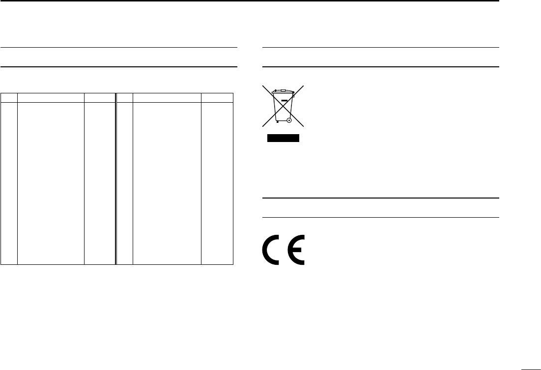
DISPOSAL
The crossed-out wheeled-bin symbol on your
product, literature, or packaging reminds you
that in the European Union, all electrical and
electronic products, batteries, and
accumulators (rechargeable batteries) must be
taken to designated collection locations at the
end of their working life. Do not dispose of
these products as unsorted municipal waste. Dispose of
them according to the laws in your area.
•List of Country codes (ISO 3166-1)
Country Codes Country Codes
1 Austria AT 18 Liechtenstein LI
2 Belgium BE 19 Lithuania LT
3 Bulgaria BG 20 Luxembourg LU
4 Croatia HR 21 Malta MT
5Czech Republic CZ 22 Netherlands NL
6 Cyprus CY 23 Norway NO
7 Denmark DK 24 Poland PL
8 Estonia EE 25 Portugal PT
9 Finland FI 26 Romania RO
10 France FR 27 Slovakia SK
11 Germany DE 28 Slovenia SI
12 Greece GR 29 Spain ES
13 Hungary HU 30 Sweden SE
14 Iceland IS 31 Switzerland CH
15 Ireland IE 32 Turkey TR
16 Italy IT 33 United Kingdom GB
17 Latvia LV
COUNTRY CODE LIST
ABOUT CE AND DOC
Hereby, Icom Inc. declares that the versions
of IC-M330E/IC-M330GE which have the
“CE” symbol on the product, comply with the
essential requirements of the Radio Equipment
Directive, 2014/53/EU, and the restriction of the use of
certain hazardous substances in electrical and electronic
equipment Directive, 2011/65/EU. The full text of the EU
declaration of conformity is available at the following internet
address:
http://www.icom.co.jp/world/support

New2001
x
RECOMMENDATION
CLEAN THE FRONT PANEL THOROUGHLY WITH FRESH
WATER after exposure to saltwater, and dry it before
operating. Otherwise, the front panel’s keys, switches and
controllers may become unusable, due to salt crystallization.
Icom, Icom Inc. and Icom logo are registered trademarks of Icom
Incorporated (Japan) in Japan, the United States, the United
Kingdom, Germany, France, Spain, Russia, Australia, New Zealand,
and/or other countries.
AquaQuakeTM is a trademark of Icom Incorporated.
NOTE: If the front panel’s waterproof protection appears
defective, carefully clean it with a soft, wet (fresh water)
cloth, then, dry it before operating.
The front panel may lose its waterproof protection if the
case or connector cover is cracked or broken, or the
transceiver has been dropped.
Contact your Icom distributor or your dealer for advice.
INSTALLATION NOTE
Installation:
The installation of this equipment should be made in such a
manner as to respect the EC recommended electromagnetic
eld exposure limits. (1999/519/EC)
The maximum RF power available from this device is 25
watts. The antenna should be installed as high as possible
for maximum efciency and the installation height should be
at least 1.76 meters above any accessible position. In the
case where an antenna cannot be installed at a reasonable
height, then the transmitter should neither be continuously
operated for long periods if any person is within a distance
of 1.76 meters of the antenna, nor operated at all if any
person is touching the antenna.
It is recommended that antenna of a maximum gain of
3 dB is used. If higher gain antenna are required then
please contact your Icom distributor for revised installation
recommendations.
Operation:
The exposure to RF electromagnetic eld is only applicable
when this device is transmitting. This exposure is naturally
reduced due to the nature of alternating periods of receiving
and transmitting. Keep your transmissions to the minimum
necessary.
New2001
xi
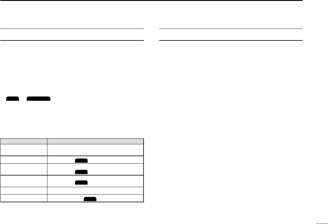
KEY ICON DESCRIPTION
The keys are described in this manual as followings:
zThe keys which have an icon on it are described with the
characters “[ ]”.
Example: [MENU], [CLR]
zThe software keys are described with the icon such as
ENT
or
DISTRESS
. The function of the keys are shown at
the bottom of the display. Push the key below the desired
function.
zyou can use the following keys in the Menu screen.
FUNCTION ACTION
Select Rotate [DIAL], or push [▼] or [▲].
Enter Push [ENT],
ENT
, or [DIAL]
Go to the next tree
level Push [ENT],
ENT
, [DIAL], or [►].
Go back to the
previous tree level Push [CLR],
BACK
, or [◄].
Cancel Push [CLR].
Exit Push [MENU] or
EXIT
TABLE OF CONTENTS
IMPORTANT ......................................................................... ii
FEATURES ........................................................................... ii
EXPLICIT DEFINITIONS ...................................................... ii
IN CASE OF EMERGENCY .................................................iii
RADIO OPERATION WARNING ......................................... iv
AVERTISSEMENT POUR LES OPÉRATEURS RADIO ...... v
FCC INFORMATION ........................................................... vi
NOTE ................................................................................... vi
PRECAUTIONS ...................................................................vii
PRÉCAUTIONS ..................................................................viii
COUNTRY CODE LIST ....................................................... ix
DISPOSAL ........................................................................... ix
ABOUT CE AND DOC ......................................................... ix
RECOMMENDATION ........................................................... x
INSTALLATION NOTE .........................................................x
KEY ICON DESCRIPTION .................................................. xi
1. OPERATING RULES .......................................................1
2. PANEL DESCRIPTION .................................................... 2
■Front Panel ..................................................................2
■Function Display ..........................................................3
■Software keys ..............................................................4
■Microphone ..................................................................6
3. PREPARATIONS .............................................................7
■Entering the MMSI code ..............................................7
■Entering the ATIS ID (For Dutch and German versions) ....8

New2001
xii
TABLE OF CONTENTS
4. BASIC OPERATION ........................................................9
■Selecting a channel ......................................................9
■ Adjusting the volume level ......................................... 11
■ Adjusting the squelch level ........................................ 11
■ Adjusting the backlight or the display contrast ........... 12
■Setting the Call channel .............................................12
■Receiving and transmitting ........................................13
■Microphone Lock function ..........................................13
■ AquaQuake Water Draining function ..........................14
■Editing a channel name .............................................14
5. SCAN OPERATION (Except for the Dutch Version)............15
■Scan types ................................................................15
■Setting Favorite channels ..........................................16
■Starting a scan ...........................................................16
6. DUALWATCH/TRI-WATCH (Except for the Dutch Version) 17
■Description .................................................................17
■Operation ...................................................................17
■DSC address ID .........................................................18
7. DSC OPERATION .........................................................18
■Entering the position and time ...................................20
■Sending DSC calls (Distress) .....................................21
■DSC Settings .............................................................24
8. MENU SCREEN ............................................................27
■Using the Menu screen ..............................................27
■Menu items description ..............................................29
9. CONNECTIONS AND MAINTENANCE ......................... 33
■Connections ...............................................................33
■Antenna ......................................................................35
■Fuse replacement ......................................................35
■Cleaning ..................................................................... 35
■Supplied accessories .................................................35
■Mounting the transceiver ............................................36
■MBF-5 installation ......................................................37
■Specications ............................................................. 38
10. SPECIFICATIONS ....................................................... 38
■Options .......................................................................39

1
New2001
1
2
3
4
5
6
7
8
9
10
11
12
13
14
15
16
1
OPERATING RULES
DPriorities
• Read all rules and regulations pertaining to priorities and
keep an up-to-date copy handy. Safety and distress calls
take priority over all others.
• You must monitor Channel 16 when you are not operating
on another channel.
• False or fraudulent distress calls are prohibited under law.
DPrivacy
• Information overheard but not intended for you cannot
lawfully be used in any way.
• Indecent or profane language is prohibited.
DRadio licenses
(1) SHIP STATION LICENSE
You must have a current radio station license before using
the transceiver. It is unlawful to operate a ship station which
is not licensed.
Inquire through your dealer or the appropriate government
agency for a Ship-Radiotelephone license application. This
government-issued license states the call sign which is your
craft’s identication for radio purposes.
(2) OPERATOR’S LICENSE
A Restricted Radiotelephone Operator Permit is the license
most often held by small vessel radio operators when a
radio is not required for safety purposes.
The Restricted Radiotelephone Operator Permit must be
posted or kept with the operator. Only a licensed radio
operator may operate a transceiver.
However, non-licensed individuals may talk over a
transceiver if a licensed operator starts, supervises, ends
the call and makes the necessary log entries.
A current copy of the applicable government rules and
regulations is only required to be on hand for vessels in
which a radio telephone is compulsory. However, even
if you are not required to have these on hand it is your
responsibility to be thoroughly acquainted with all pertinent
rules and regulations.
NOTE: Even though the transceiver is capable of
operation on VHF marine channels 3, 21, 23, 61, 64,
81, 82 and 83, according to FCC regulations these
simplex channels cannot be lawfully used by the general
population in USA waters.
2
New2001
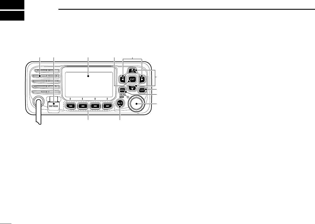
2PANEL DESCRIPTION
■Front Panel
t
u
y
w
io
e
r
qFunction display (p.4)Speaker
1DISTRESS KEY [DISTRESS]
Hold down for 3 seconds to transmit a Distress call.
2ENTER KEY
Push to set the entered data, selected item, and so on.
3LEFT/RIGHT KEYS [◄]/[►]
zPush to scroll the Software Key functions.
zPush to select a character or number in the entry
mode.
4UP/DOWN KEYS [▲]/[▼]
zPush to select an operating channel, Menu items,
Menu settings, and so on.
z Push to select a character or number in the entry
mode.
5CLEAR KEY [CLR]
Push to cancel the entered data, or to return to the
previous screen.
6MENU KEY
Push to display or close the Menu screen.
7POWER/VOLUME/SQUELCH SWITCH [PWR/VOL/
SQL/
DIAL]
zHold down for 1 second to turn the transceiver ON or
OFF.
zPush once to display the volume level setting screen,
then rotate to adjust the volume level.
zPush twice to display the squelch level setting screen,
then rotate to adjust the squelch level.
zRotate to select an item in the Menu screen.
zPush to select a character or number, or rotate to move
the cursor in the entry mode.
8CHANNEL 16/CALL CHANNEL KEY [16/C]
zPush to select Channel 16.
zHold down for 1 second to select the Call channel.
9SOFTWARE KEYS
Scroll the key functions pushing [◄] or [►], then push
either of the 4 software keys to select the function
displayed at the bottom of the display.
See “Software keys” on pages 4~5 for details.
3
PANEL DESCRIPTION 2
New2001
1
2
3
4
5
6
7
8
9
10
11
12
13
14
15
16
New2001
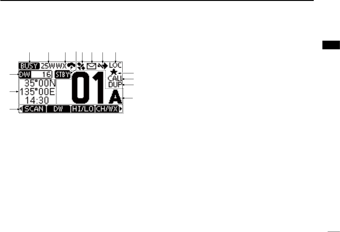
■Function Display
q w ie tr
!1
y u
!2
!3
!4
!0
o
!5
1STATUS ICON
• TX: Displayed while transmitting.
• BUSY: Displayed while receiving, or the squelch is
open.
2POWER INDICATOR
• 25W: High power
• 1W: Low power
3CHANNEL GROUP ICON
Displays the selected channel group, INT (International),
USA, CAN (Canada), ATIS, WX (Weather channel), or
DSC.
LThe selectable channels differ, depending on the version or
presettings.
4STATUS ICON
• STBY: Displayed when in the Standby mode.
• RT: Displayed when the channel is changed while
receiving or transmitting a signal. (For only the
USA verion)
5GPS ICON
• Displayed when valid GPS position data is received.
• Blinks while no position data is received.
6MAIL ICON (Displayed when there is an unread DSC
message.
• Blinks until one of the called messages is read.
7CHANNEL SWITCH ICON
• Displayed when the “CH Auto Switch” is set to “Ignore”
or “Manual”
• Blinks when the “DSC Switch” is OFF.
8LOCAL ICON
Displayed when the RF Attenuation is ON. (For only the
USA version)
9FAVORITE CHANNEL ICON
Displayed when a Favorite channel is selected.
CALL CHANNEL ICON
Displayed when a Call channel is selected.
DUPLEX CHANNEL ICON
Displayed when a Duplex channel is selected.
4
2PANEL DESCRIPTION
New2001
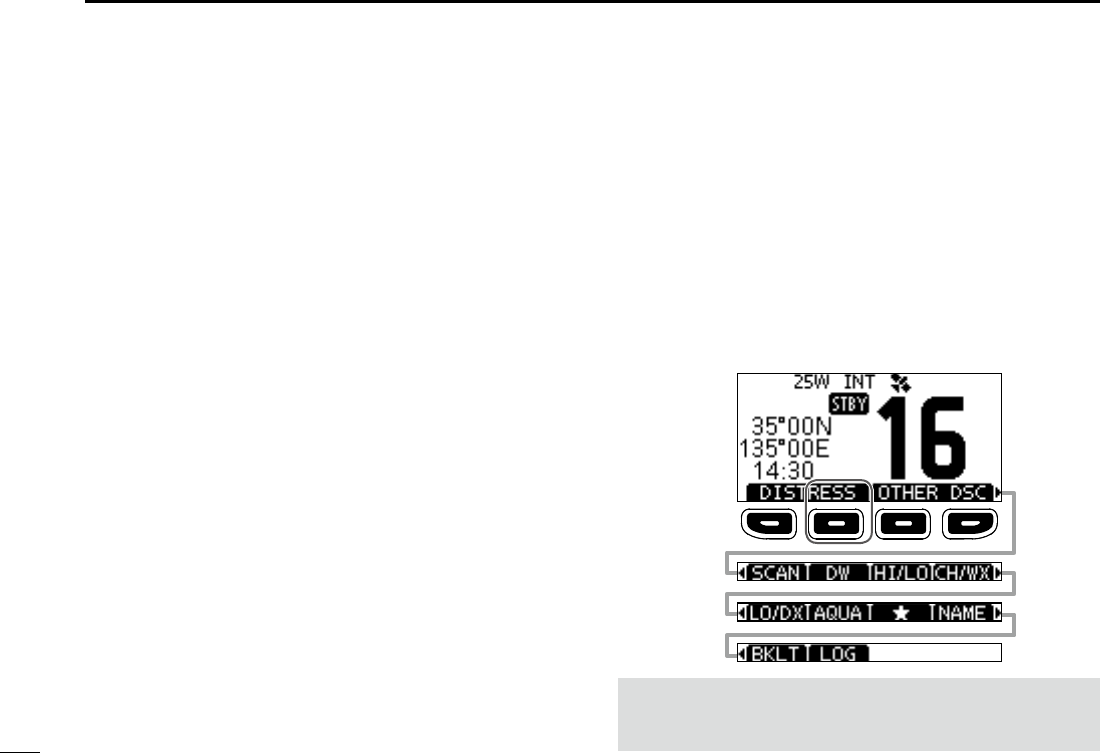
■Software keys
Various often-used functions are assigned to the software
keys for easy access. The functions’ icons are displayed
above the software keys, as shown below.
DUsing the software keys
Selecting a software key function
Push[◄]or[►]toslidethroughtheselectablefunctions
that are assigned to the software keys.
Push the software key under the function’s icon to select the
function.
NOTE: The displayed icons or their order may differ,
depending on the transceiver version or the presetting. Ask
your dealer for details.
CALL CHANNEL NUMBER
Displays the selected operating channel number.
LFor the USA and Canada Channels, “A” is displayed when a
simplex channel is selected.
SOFTWARE KEY FUNCTION DISPLAY
The functions of each keys are displayed.
See “Software keys” on the next page for details.
POSITION/TIME REAOUTS
Readouts the current position and time when valid GPS
data is received, or when manually entered.
• The letter after the time shows the source of the position
data, I: internal, E: external, M: manual, L: local.
Received GPS data:
• “??” blinks if no GPS data is received for 30 seconds after
receiving valid GPS data, and then “??” and a warning
message are displayed alternately after 10 minutes.
• A warning message is displayed if no GPS data is received for 4
hours after receiving valid GPS data.
• “NO POS NO TIME” is displayed if no GPS data is received for
2 minutes after turning ON the transceiver, and then a warning
message is displayed.
Manually entered GPS data:
• A manually entered GPS data is valid for 4 hours, and then a
warning message is displayed after 4 hours.
SCAN INDICATOR
• “SCAN” or “SCAN 16” is displayed while scanning.
• “DW” or “TW” and watched channel number
is displayed
while using the Dualwatch or Tri-watch function.
Push [►]
Push [◄]
5
PANEL DESCRIPTION 2
New2001
1
2
3
4
5
6
7
8
9
10
11
12
13
14
15
16
Channel/Weather channel
CH/WX
Push to select regular channels or Weather channels.
L The Weather channel is for only the USA version.
CHAN
is displayed for other versions.
L While the Call channel or Channel 16 is displayed, push this key
to return to the regular channel mode.
Low
LO/DX
(For only the USA version)
Push to turn the Attenuator ON or OFF.
AquaQuake
AQUA
Hold down to turn ON the AquaQuake function to clear
water from the speaker grill.
Favorite channel
z Push to select a Favorite channel.
z Hold down for 1 second to set/release the displayed
channel as a Favorite channel.
Channel Name
NAME
Push to edit the name of the displayed channel.
Backlight
BKLT
Push to display the backlight brightness adjustment screen.
LWhileintheadjustmentmode,push[▲]/[▼][◄]/[►]orrotate
[DIAL] to adjust the brightness to between 1 and 7, or OFF.
LOG
LOG
Push to display the received call log or distress message log.
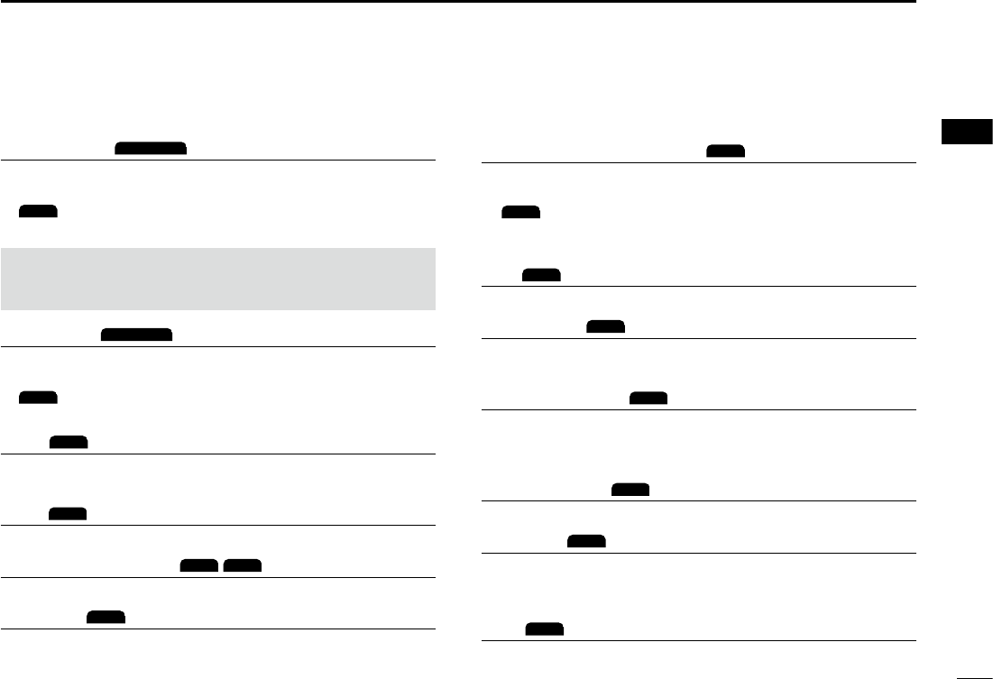
DSoftware keys
Distress Call
DISTRESS
Push to display the “Distress” screen to select the nature of
the call, then to make a call.
L
DTRS
is displayed in the Multiple-task mode (for only the USA
version).
NEVER MAKE A DISTRESS CALL IF YOUR SHIP OR A PERSON
IS NOT IN AN EMERGENCY. A DISTRESS CALL SHOULD BE
MADE ONLY WHEN IMMEDIATE HELP IS NEEDED.
Other DSC
OTHER DSC
Push to compose an Individual call, Group call, All Ships call
or a Test call.
L
OTH
is displayed in the Multiple-task mode (for only the USA
version).
Task
TASK
(For only the USA version) (p. ??)
Displayed only in the Multiple-task mode. Push to display
the task list.
Scan
SCAN
Push to start or stop a Normal or Priority scan.
Dualwatch/Tri-watch
DW
/
TW
Push to start or stop Dualwatch or Tri-watch.
High/Low
HI/LO
Push to set the output power to high or low.
LSome channels are set to only low power.

6
2PANEL DESCRIPTION
New2001
■Microphone
1PTT SWITCH [PTT]
Hold down to transmit, release to receive.
w UP/DOWN KEYS [▲]/[▼]
Push to change the channel.
L When the “FAV on MIC” item is set to “ON,” you can select
Favorite channels, change scanning direction or manually
resume a scan.
e TRANSMIT POWER KEY [HI/LO]
zPush to set the power level to high or low.
zSome channels are set to only low power.
zWhile holding down this key, turn ON the transceiver to
turn the Microphone Lock function ON or OFF.
r CHANNEL 16/CALL CHANNEL KEY [16/C]
zPush to select Channel 16.
zHold down for 1 second to select the Call channel.
• The “CALL” icon is displayed.
q
w
e
Microphone
r
7
3
PREPARATIONS
New2001
1
2
3
4
5
6
7
8
9
10
11
12
13
14
15
16
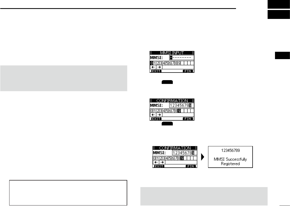
■Entering the MMSI code
The Maritime Mobile Service Identity (MMSI: DSC self ID)
code consists of 9 digits. You can only enter the code when
turning ON the transceiver for the rst time.
4. Repeat step 3 to enter all 9 digits.
5. Push
FIN
to set the entered code.
• The “Conrmation” screen is displayed.
6. Enter your MMSI code again to confirm.
7. Push
FIN
to set the entered code.
• When your MMSI code is successfully entered, “MMSI
Successfully Registered” is briey displayed, and then
enters the operating screen.
L Your MMSI code is also displayed on the operating screen.
This initial code entry can be done only once.
After entering, it can be changed only by your dealer
or distributor. If your MMSI code has already been
entered, this entry is not necessary.
1. Hold down [DIAL] for 1 second to turn ON the
transceiver.
• Three short beeps sound, and “Push [ENT] to Register your
MMSI” is displayed.
2. Push [ENT] to start entering the MMSI code.
• The “MMSI Input” screen is displayed.
L Push [CLR] twice to skip the entry.
If you skip the entry, you cannot make a DSC call. To enter
the code after skipping, turn OFF the power, and then turn
it ON again.
3. Enter the MMSI code.
NOTE: For Dutch and German versions, the ATIS ID is also
required to be set. See the next page and set it.
TIP:
• Select a number using [◄] and [►].
• Push [ENT] to enter the selected number.
• Select “←” or “→,” or rotate [DIAL] to move the cursor.
8
3PREPARATIONS
New2001
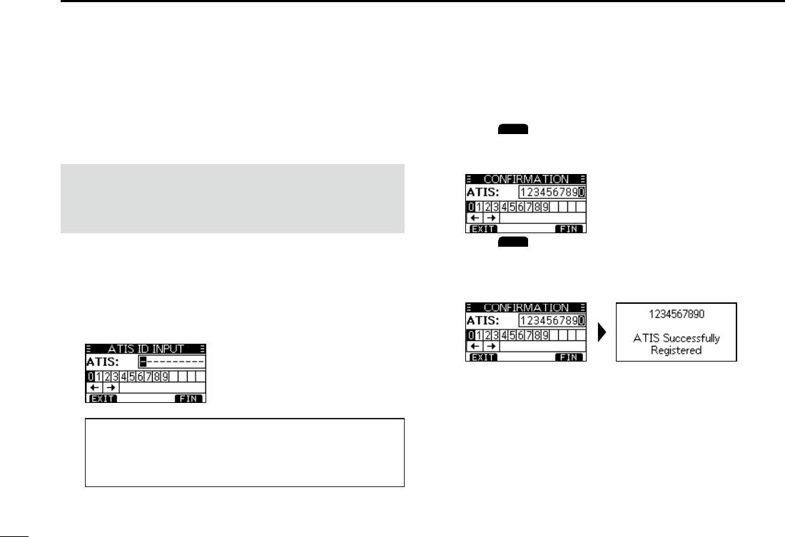
The Automatic Transmitter Identication System (ATIS) ID
consists of 10 digits. You can enter the ID in the “ATIS ID
Input” item on the Menu screen.
■Entering the ATIS ID (For Dutch and German versions)
This ID entering can be done only once. After entering,
it can be changed only by your dealer or distributor.
If your ATIS ID has already been entered, this entry is
not necessary.
1. Push [MENU].
• The Menu screen is displayed.
2. Push [▲] or [▼], or rotate [DIAL] to select “ATIS ID
Input,” then push [ENT] to start entering.
• The “ATIS ID Input” screen is displayed.
3. Enter your ATIS ID.
4. Repeat step 3 to enter all 10 digits.
5. Push
FIN
to set the entered ID.
• The “Conrmation” screen is displayed.
6. Enter your ATIS ID again to confirm.
7. Push
FIN
to set the entered ID.
• When your ATIS ID is successfully entered, the screen
displays “ATIS ID Successfully Registered,” and then enters
the operating screen.
L You can check the ATIS ID in “Radio Info” on the Menu screen.
TIP:
• Select a number using [◄] and [►].
• Push [ENT] to enter the selected number.
• Select “←” or “→,” or rotate [DIAL] to move the cursor.
9
New2001
1
2
3
4
5
6
7
8
9
10
11
12
13
14
15
16
4
BASIC OPERATION
■Selecting a channel
DRegular Channel
You can select a channel by pushing [▲] or [▼].
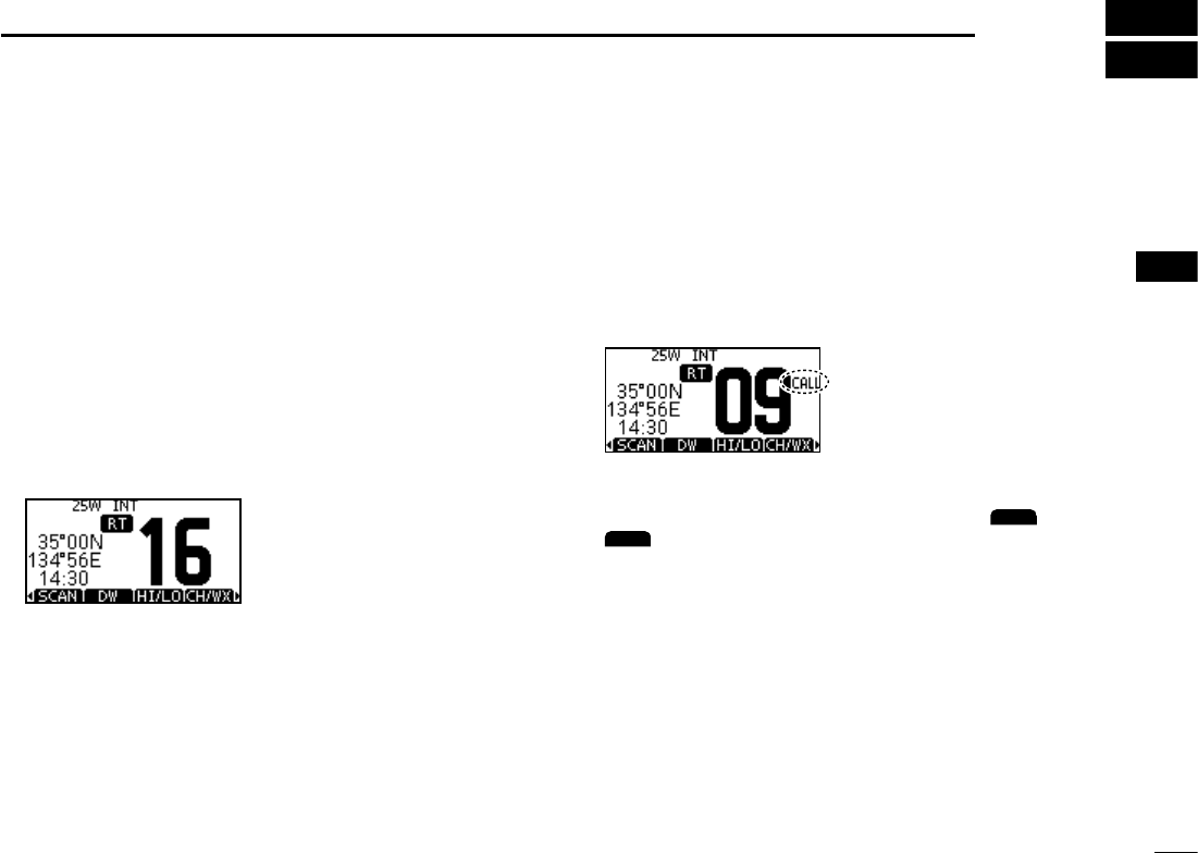
DChannel 16
Channel 16 is the distress and safety channel. It is used to
establish the initial contact with a station and for emergency
communications. Channel 16 is monitored during both
Dualwatch and Tri-watch. While in the standby mode, you
must monitor Channel 16.
zPush [16/C] to select Channel 16.
L To return to the previously selected channel, push the software
key below [CHAN] or [CH/WX].
DCall channel
Each Channel Group has separate leisure-use Call
channels. The Call channel is monitored during Tri-watch.
The Call channels can be selected and used to store your
most often used channel in each Channel Group, for quick
recall.
Hold down [16/C] for 1 second to select the Call channel.
• The Call channel number and “CALL” are displayed.
L To return to the previously selected channel, push
CHAN
or
CH/WX
.
10
4BASIC OPERATION
New2001
DSelecting a Channel Group
Channel Groups are preset into your transceiver. You can select
the Channel Group between USA, International, Canadian,
DSC, and ATIS depending on the transceiver version.
Version Preset Channel Group
USA INT CAN DSC ATIS
USA
UK
European
Dutch
German
Chinese
Australian
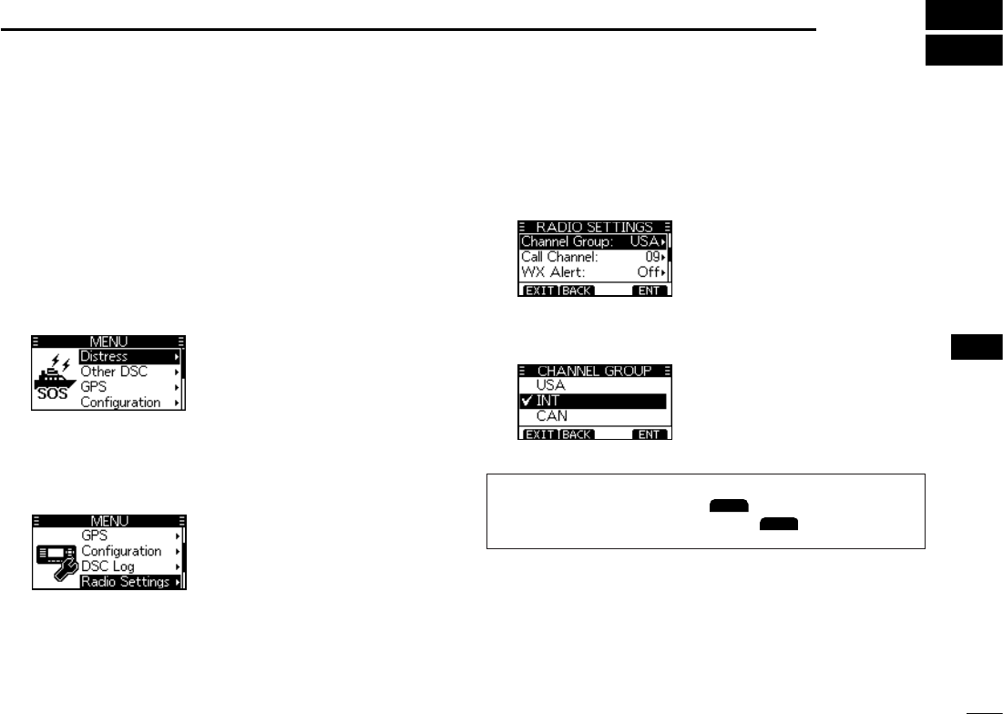
1. Push [MENU].
• The Menu screen is displayed.
2. Push [▲], [▼] or rotate [DIAL] to select “Radio
Settings,” then push [ENT].
• The “RADIO SETTINGS” screen is displayed.
3. Push [▲], [▼] or rotate [DIAL] to select “Channel
Group,” then push [ENT].
• The “CHANNEL GROUP” screen is displayed.
4.
Push [▲], [▼] or rotate [DIAL] to select a Channel
Group, and then push [ENT].
Lpush
EXIT
to exit the Menu screen.
L The selected Channel Group’s icon is displayed on the
operating screen.
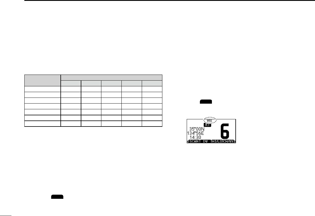
DWeather channels and Weather Alert
For the USA an Australian versions, the transceiver has
10 preset Weather channels. You can use these channels
to monitor broadcasts from the National Oceanographic
and Atmospheric Administration (NOAA). The transceiver
automatically detects a Weather alert tone on the selected
weather channel, or while scanning.
Selecting a Weather channel
1. Push
CH/WX
.
• “WX” is displayed on the operating screen instead of the
Channel Group icon.
2. Push [▲] or [▼] to select a Weather channel.
11
BASIC OPERATION 4
New2001
1
2
3
4
5
6
7
8
9
10
11
12
13
14
15
16
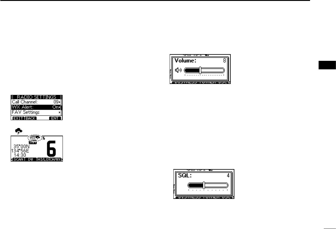
Setting the Weather Alert
1. Push [MENU].
2. Push [▲], [▼], or rotate [DIAL] to select “Radio
Settings,” and then push [ENT].
• The “RADIO SETTINGS” screen is displayed.
3. Select “WX Alert,” and then push [ENT].
• The “WX Alert” screen is displayed.
4. Select “On W/Scan” (On with scan) or “On.”
• “ ” is displayed next to the weather channel icon.
■ Adjusting the volume level
zRotate [DIAL] to adjust the audio volume level.
L If no key is pushed for 5 seconds, the screen
automatically closes.
■ Adjusting the squelch level
Squelch enables the audio to be heard only while receiving a
signal that is stronger than the set level. A higher level blocks
weak signals, so that you can receive only stronger signals.
A lower level enables you to hear weak signals.
1. Push [VOL/SQL] twice.
• The squelch level adjustment screen is displayed.
2. Rotate [DIAL] to adjust the volume level.
L If no key is pushed for 5 seconds, the adjustment screen
automatically closes.
12
4BASIC OPERATION
New2001
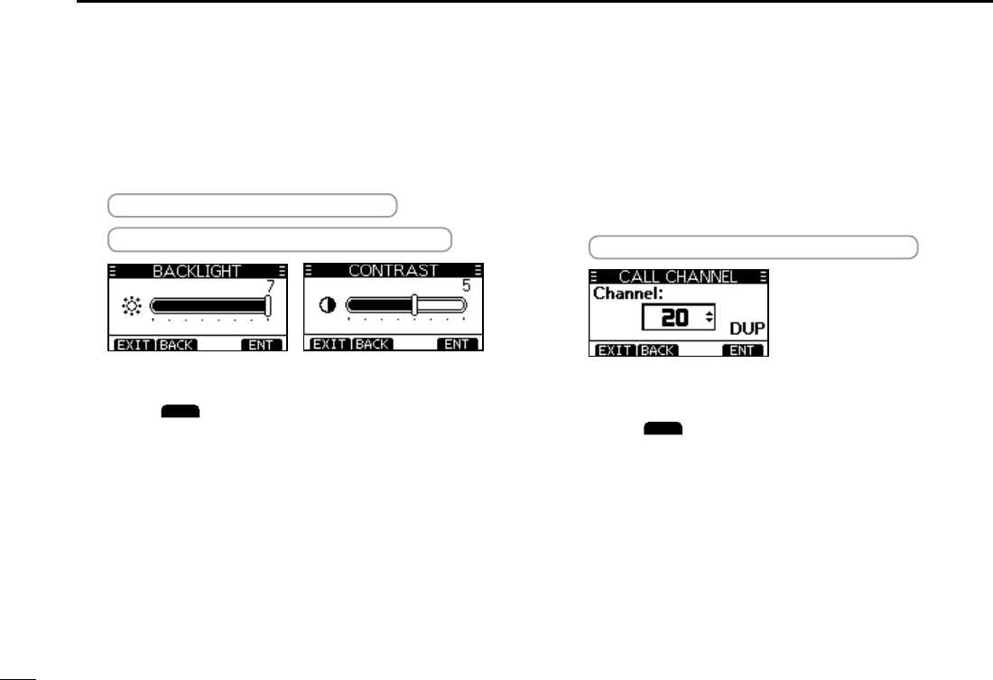
■Setting the Call channel
By default, a Call channel is set in each Channel Group.
You can set your most often-used channel as your Call
channel in each Channel Group for a quick recall.
1. Display the “CALL CHANNEL” screen.
[MENU] > Radio Settings > Call Channel
2. Push [▲], [▼], or rotate [DIAL] to select the channel.
3. Push [ENT] to set the selected channel as the Call
channel.
L Push
EXIT
to return to the operating screen.
■ Adjusting the backlight or
the display contrast
1. Display the “BACKLIGHT” or “CONTRAST” screen.
[MENU] > Conguration > Backlight
[MENU] > Conguration > Display Contrast
2. Push [▲], [▼], or rotate [DIAL] to Adjust, then push
[ENT] to set.
Lpush
EXIT
to exit the Menu screen.
13
BASIC OPERATION 4
New2001
1
2
3
4
5
6
7
8
9
10
11
12
13
14
15
16
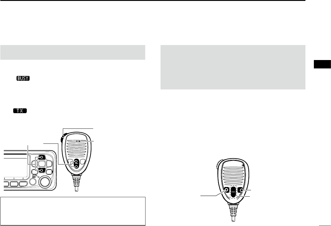
■Receiving and transmitting
CAUTION: Transmitting without an antenna may damage
the transceiver.
1. Push [▲] or [▼] to select the channel to call.
L You cannot transmit on Channel 70.
L is displayed while receiving a signal.
LYou can also select the channel with [▲] or [▼] on the
microphone. (only when the FAV on MIC is OFF (p. 53))
2. Hold down [PTT] on the microphone and speak into the
microphone.
• is displayed while transmitting.
3. Release [PTT] to receive.
TIP: To maximize the readability of your transmitted signal,
pause for a second after pushing [PTT] and hold the
microphone 5 to 10 cm (2 to 4 inches) from your mouth,
and then speak at your normal voice level.
NOTE:
• Except for the Export version, the Time-out Timer function
cuts OFF transmission after 5 minutes of continuously
transmitting, to prevent prolonged transmission.
• The Noise Cancel function reduces random noise
components in the transmit and/or received signal.
■Microphone Lock function
The Lock function electronically locks all keys [▲], [▼],
[16/C], and [H/L] on the microphone to prevent accidental
channel changes or functions access.
While holding down [HI/LO] on the microphone, hold down
[PWR] (Dial) for 1 second to turn the Lock function ON or
OFF.
Hold down to transmit.
Release to receive.
Select a channel. Speak to the
Microphone
[16/C]
[▲]/[▼]
[HI/LO]
14
4BASIC OPERATION
New2001
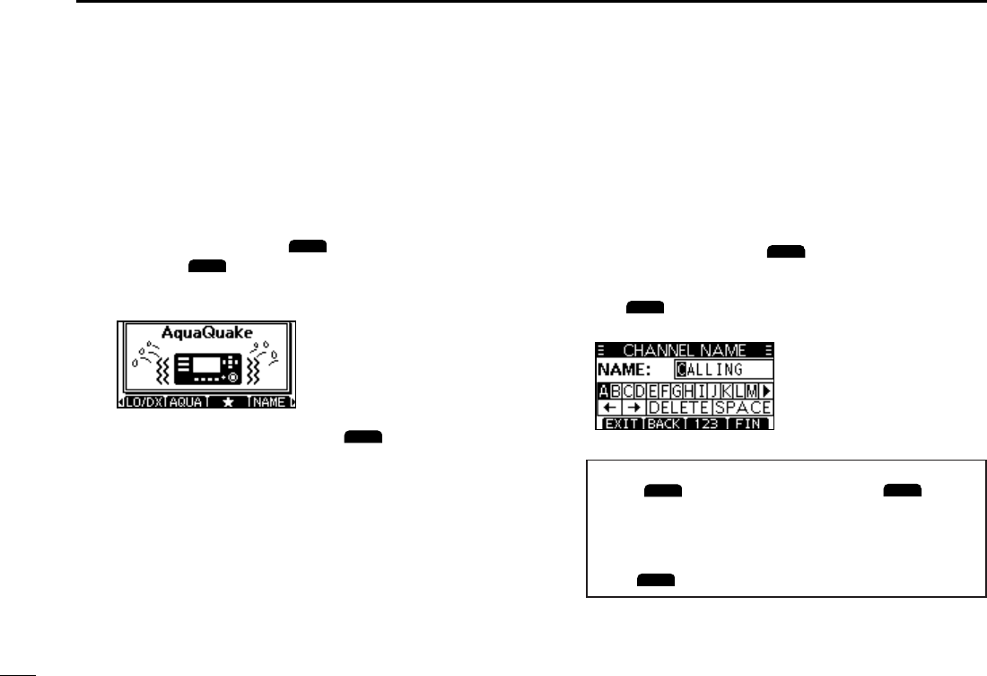
■Editing a channel name
You can edit the name of each operating channel and weather
channel, using numbers, uppercase letters, symbols, and
a space. This enables easy recognition of the channels or
stations. All VHF marine channels are set with default names.
1. Push [▲] or [▼] to select the channel to edit.
2. Push [◄] or [►] to select
NAME
.
L You cannot edit a channel name during Dualwatch, Tri-watch,
or a Scan.
3. Push
NAME
.
• The “Channel Name” screen is displayed.
4. Edit the channel name.
TIP:
• Select
!$?
to enter characters, and select
123
to enter
numbers and letters.
• Select characters or space using [▲]/[▼]/[◄]/[►].
• Push [ENT] to enter the selected character.
• Select “←” or “→,” or rotate [DIAL] to move the cursor.
• Push
EXIT
to cancel editing.
5. Push [FIN] to set the edited name.
■ AquaQuake Water Draining
function
Water in the speaker grill may mufe the sound coming
from the speaker. The AquaQuake Water Draining function
removes water from the speaker grill by vibrating the speaker.
1. Push [◄] or [►] to select
AQUA
.
2. Hold down
AQUA
to turn ON the function.
• A low frequency vibration beep sounds to drain the water,
regardless of the volume level setting.
L This function is activated for a maximum of 10 seconds,
even if you continue to hold down
AQUA
.
3. Release the key to turn OFF the function.
15
New2001
1
2
3
4
5
6
7
8
9
10
11
12
13
14
15
16
5
SCAN OPERATION (Except for the Dutch Version)
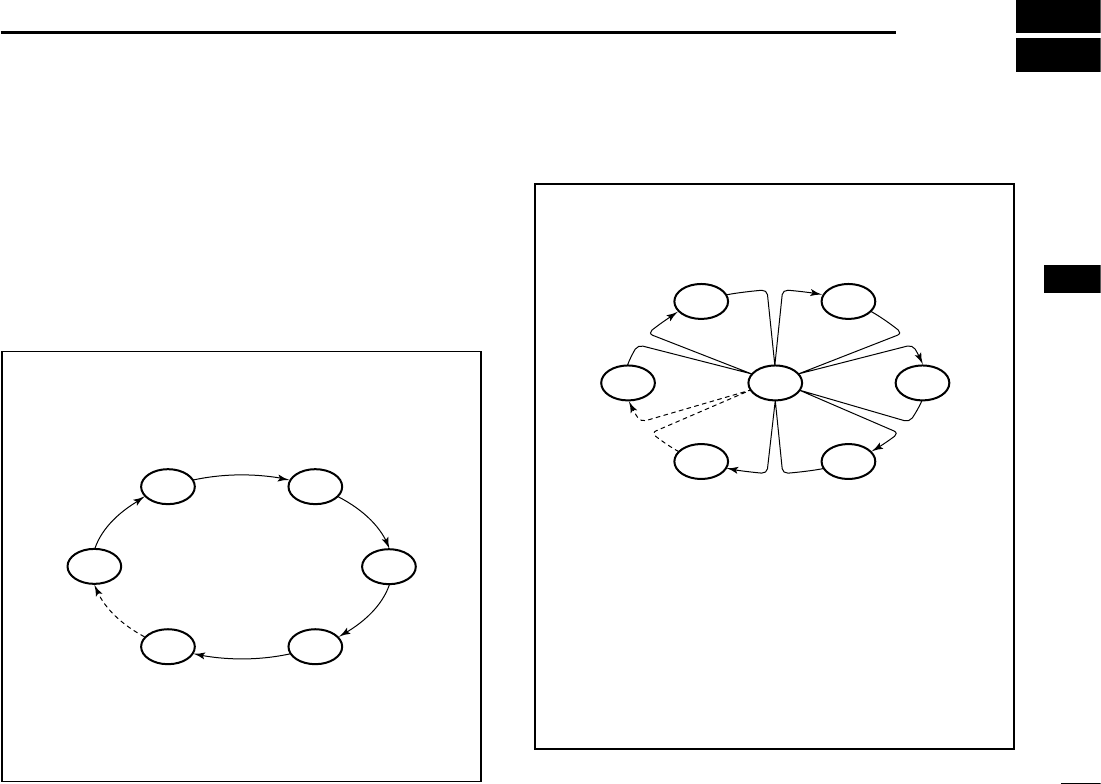
■Scan types
You can nd ongoing calls by scanning the Favorite channels.
Before starting a scan, you need to:
• Set the channels that you want to scan as Favorite
channels. (p. 17)
LOnly the Favorite channels are scanned.
• Set the scan type to “Priority Scan” or “Normal Scan” on
the “Radio Settings” screen. (p. 55)
WX*
CH 01
CH 16
CH 02
CH 05 CH 04
CH 03
Priority Scan
The Priority Scan sequentially searches through all
Favorite channels, while also monitoring Channel 16.
When a signal is received:
On Channel 16
The scan pauses until the signal disappears.
On a channel other than Channel 16
The scan becomes Dualwatch until the signal
disappears.
*For USA, Australian, and Export versions.
When the Weather Alert function is ON, the
previously selected Weather channel is also
scanned.
CH 01 CH 02
WX*
CH 05 CH 04
CH 03
Normal Scan
The Normal Scan sequentially searches through
all Favorite channels. However, Channel 16 is not
checked unless it is set as a Favorite channel.
*For USA, Australian, and Export versions.
When the Weather Alert function is ON, the
previously selected Weather channel is also
scanned.
New2001
16
5SCAN OPERATION (Except for the Dutch Version)
New2001
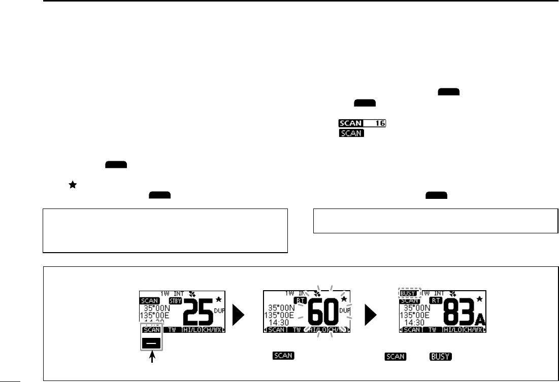
■Starting a scan
1. Select a Channel Group.
2. Push [◄] or [►] to display
SCAN
.
3. Push
SCAN
.
• The scan starts.
• “ ” is displayed during a Priority Scan, and
“ ” is displayed during a Normal Scan.
L When a signal is received, the scan pauses until the signal
disappears, or resumes after 5 seconds, depending on the
Scan Timer setting in “Radio Settings.”
L A beep sounds and “16” blinks when a signal is received on
Channel 16 during a Priority scan.
4. To stop the scan, push
SCAN
.
■Setting Favorite channels
You can quickly recall often-used channels by setting them
as Favorite channels. You can set Favorite channels in each
Channel Group.
1. Select a Channel Group.
2. Push [▲] or [▼] to select the channel you want to set as
a Favorite channel.
3. Push [◄] or [►] to display .
4. Hold down
for 1 second.
• The selected channel is set as a Favorite channel, and
“ ” is displayed.
LTo cancel the setting,
again for 1 second.
TIP: You can set all channels as Favorite channels, clear all
settings, or reset to the default. By default, some channels
are preset as Favorite channels. The preset channels differ,
depending on the transceiver version.
TIP: In order to properly receive signals, be sure to adjust the
squelch to a suitable level.
Example: Starting a Normal Scan
Push to start
When a signal is received
“ ” and “ ” are displayed.
While scanning
“” is displayed.
17
New2001
1
2
3
4
5
6
7
8
9
10
11
12
13
14
15
16
6
DUALWATCH/TRI-WATCH (Except for the Dutch Version)
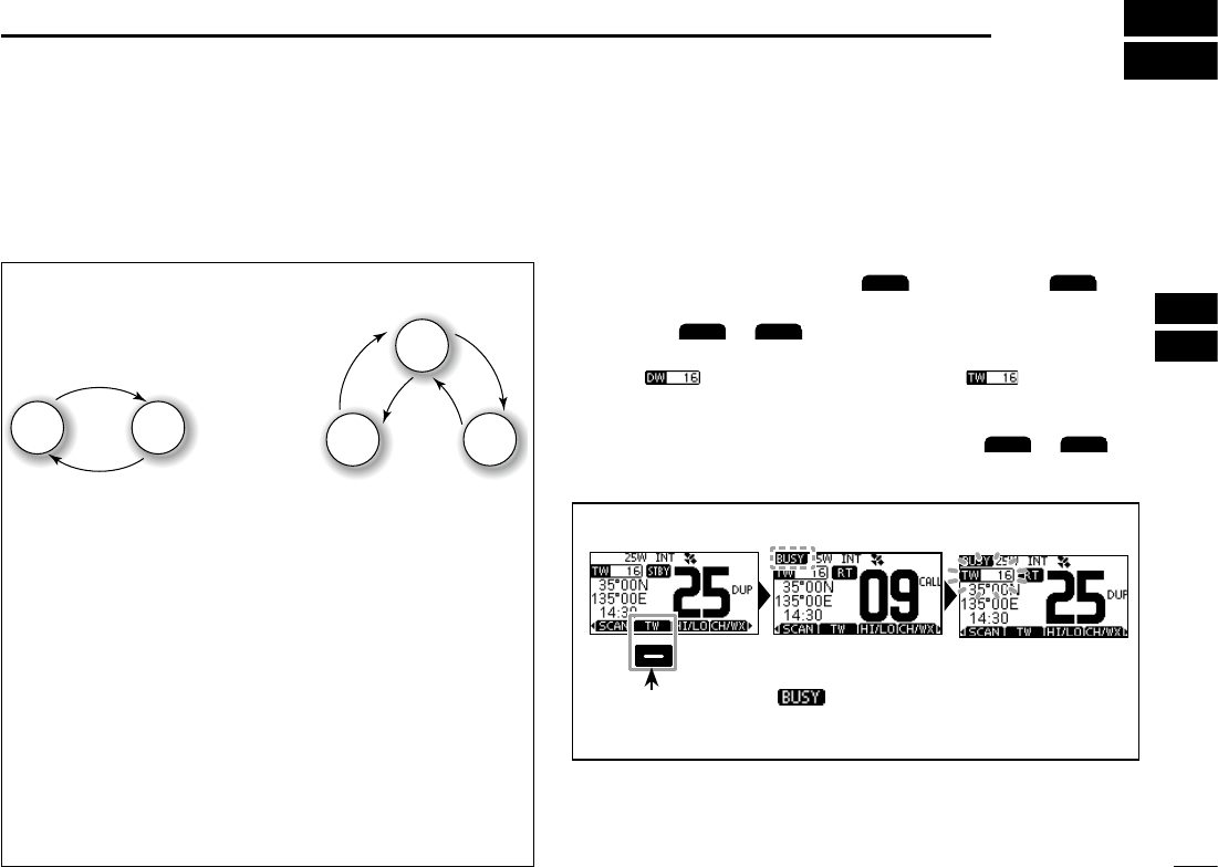
■Description
Dualwatch and Tri-watch are convenient to monitor Channel
16 while you are operating on another channel.
When a signal is received:
On Channel 16
Dualwatch/Tri-watch pauses on Channel 16 until the
signal disappears.
On the Call channel
Tri-watch switches to Dualwatch until the signal on the
Call channel disappears.
Ch 88
Ch 16
Ch 88
Ch 16
Ch 9
Normal channel
Call
channel
Normal
channel
Monitors Channel 16
while receiving on another
channel.
Monitors Channel 16 and the
Call channel while receiving
on another channel.
Dualwatch Tri-watch
■Operation
1. Select Dualwatch or Tri-watch in “Radio Settings” in the
Menu screen.
2. Push [▲] or [▼] to select a channel.
3. Push [◄] or [►] to display
DW
(Dualwatch) or
TW
(Tri-watch).
4. Push
DW
or
TW
.
• Dualwatch or Tri-watch starts.
• “ ” is displayed for Dualwatch, and “ ” is
displayed for Tri-watch.
LBeeps sound when a signal is received on Channel 16.
5. To cancel Dualwatch or Tri-watch, push
DW
or
TW
again.
Example: Operating Tri-watch on INT Channel 25.
Push to start
Signal is received on
the Call channel.
“ ” is displayed.
Signal received on
Channel 16 takes
priority. “16” blinks.
LTri-watch resumes after the signal disappears.
18
New2001
7DSC OPERATION
■DSC address ID
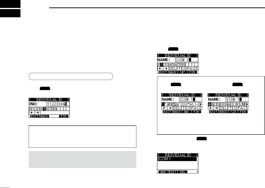
DEntering an Individual ID
You can enter a total of 60 Individual IDs, and assign names
of up to 10 characters.
1. Display the “INDIVIDUAL ID” screen.
[MENU] > DSC Settings > Individual ID
• “No ID” is displayed if no ID is entered.
2. Push
ADD
.
• “The Individual ID” entry screen is displayed.
3. Enter the Individual ID.
TIP:
• Selectanumberusing[◄]and[►].
• Push [ENT] to enter the selected number.
• Select“←”or“→,”orrotate[DIAL]tomovethecursor.
NOTE:therstdigitisxedas“0”foraGroupID.
Thersttwodigitsarexedas“0”foranyCoast
station ID.
4. Push
FIN
to start entering the name.
TIP:
• Push
!$?
to use characters, and select
ABC
to use
numbers and letters.
• Selectcharactersorspaceusing[▲]/[▼]/[◄]/[►].
• Select“◄”or“►”toscroll.
• Push [ENT] to enter the selected character.
• Select“←”or“→,”orrotate[DIAL]tomovethecursor.
5. After entering, push
FIN
to save, and return to the
previous screen.
• The entered name is displayed.
19
DSC OPERATION 7
New2001
1
2
3
4
5
6
7
8
9
10
11
12
13
14
15
16
New2001
DEntering a Group ID
Youcanenteratotalof30GroupIDs,andassignnamesof
up to 10 characters.
1. Displaythe“GROUPID”screen.
[MENU] > DSC Settings > Group ID
• “No ID” is displayed if no ID is entered.
2. Push
ADD
.
• TheGroupID’sentryscreenisdisplayed.
3. EntertheGroupIDanditsnameinthesamewayas
described on the previous page.
4. After entering, push
FIN
to save, and return to the
previous screen.
• The entered name is displayed.
NOTE:Therstdigitisxedas“0”foraGroupID.
Thersttwodigitsarexedas“0”foranyCoast
station ID.
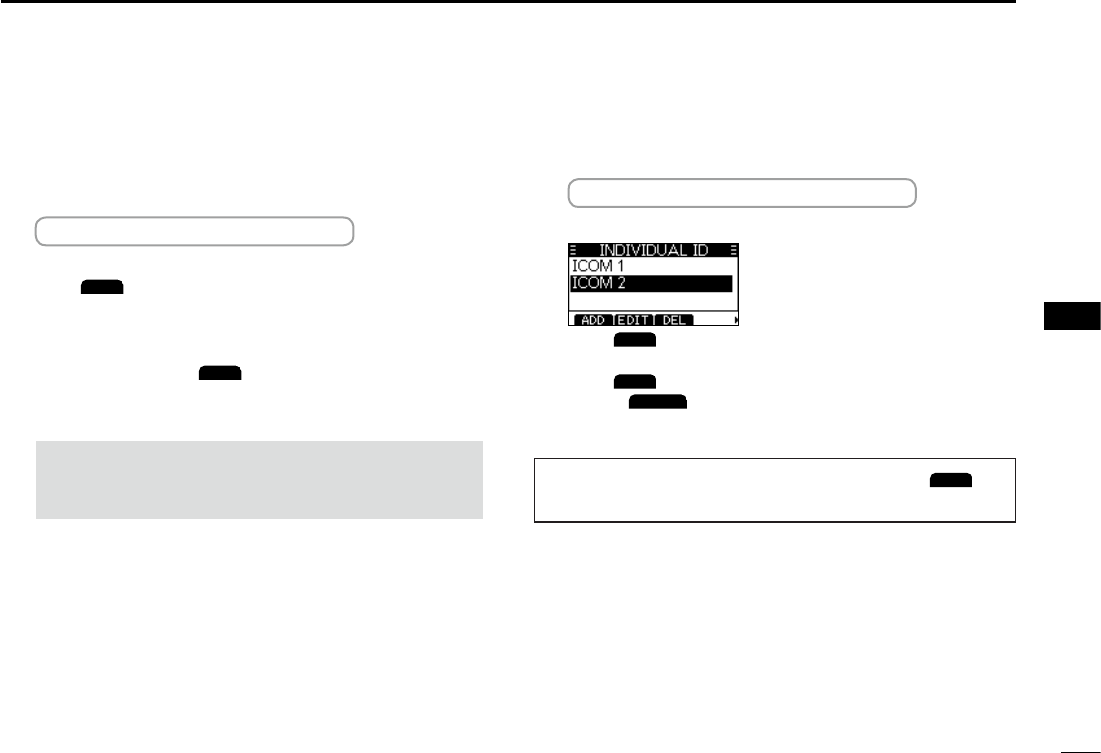
DDeleting an entered ID
(Example:DeletinganIndividualID:ICOM2)
1. Display the “INDIVIDUAL ID” screen.
[MENU] > DSC Settings > Individual ID
2. Push[▲]or[▼]toselect“ICOM2.”
3. Push
DEL
.
• “Are You Sure?” is displayed.
4. Push
OK
to delete.
L Push
CANCEL
to cancel the deletion.
• The selected ID is deleted, and then returns to the previous
screen.
TIP:YoucaneditanIDanditsnamebypushing
EDIT
in
step 3.
20
7DSC OPERATION
New2001
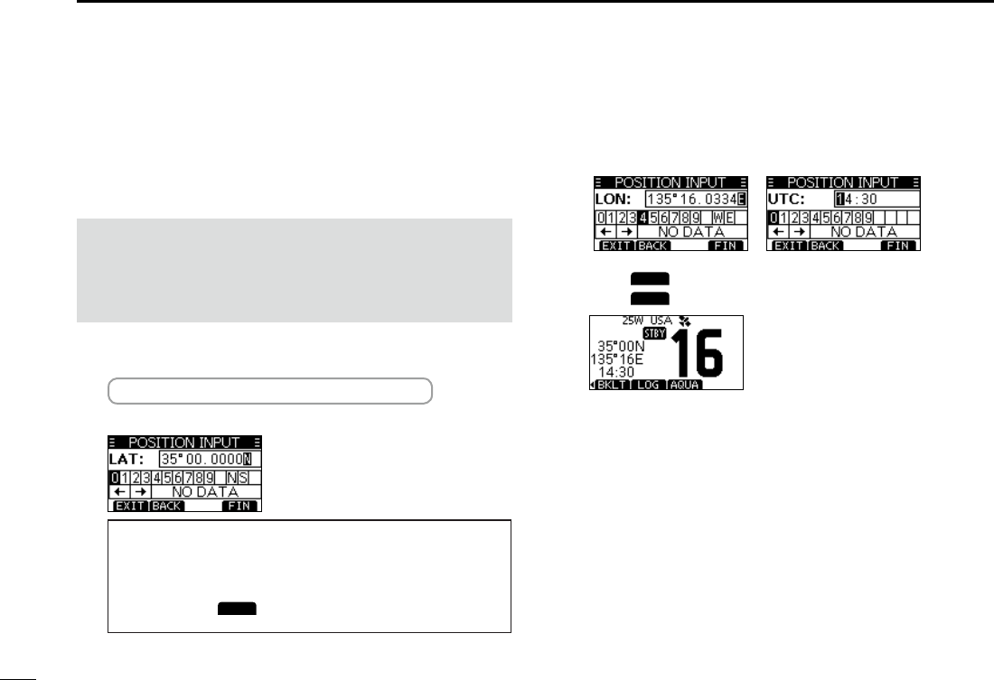
■
Entering the position and time
ADistresscallshouldincludethevessel’spositionandtime.
IfnoGPSdataisreceived,manuallyenterthepositionand
UniversalTimeCoordinated(UTC)time.
NOTE:
• ThemanualentryisdisabledwhiletheGPSdatais
received.
• The manually entered position and time is valid only for 4
hours, or until turning OFF the transceiver.
1. Display the “POSITION INPUT” screen.
[MENU] > DSC Settings > Position Input
2. Enter the latitude.
TIP:
• Selectanumberoracompassdirectionusing[▲]/[▼]/[◄]/
[►].
• Select“←”or“→,”orrotate[DIAL]tomovethecursor.
• Push [ENT] or
FIN
to enter the selected number.
3. Enter the longitude and the UTC time.
LSee the TIP in step 2 to enter.
4. Push
FIN
to set the entered position and time.
5. Push
EXIT
to return to the standby screen.
L The entered position and time are displayed on the
operating screen.
L“M”(manual)isdisplayednexttothetimedisplay.
21
DSC OPERATION 7
New2001
1
2
3
4
5
6
7
8
9
10
11
12
13
14
15
16
■Sending DSC calls (Distress)
A Distress call should be sent if, in the opinion of the Master,
the ship or a person is in distress and requires immediate
assistance.
NEVER MAKE A DISTRESS CALL IF YOUR SHIP OR A PERSON
IS NOT IN AN EMERGENCY. A DISTRESS CALL SHOULD BE
MADE ONLY WHEN IMMEDIATE HELP IS NEEDED.
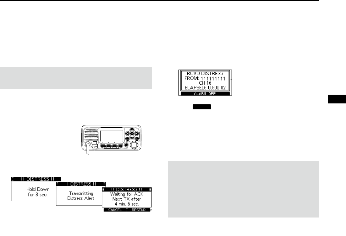
DSimple call
1. Confirm that no Distress call is being received.
2. Whileliftingupthekeycover,holddown[DISTRESS]
for3secondsuntilyouhear3shortcountdownbeeps
and a long beep sound.
• The backlight blinks.
3. Aftersending,waitforanAcknowledgementcall.
• “Waiting for ACK” is displayed.
L The Distress call is automatically sent every 3.5 to 4.5
minutes,untilanAcknowledgementisreceived,ora
Distress Cancel call is sent.
LWhenyoureceiveanAcknowledgement,alarmsounds.
4. PushanysoftwarekeytoturnOFFthealarm.
• Channel 16 is automatically selected.
5. Holddown[PTT]toexplainyoursituation.
6. Push
CANCEL
to return to the operating screen.
TIP:AdefaultDistressalertcontains:
• Natureofdistress:Undesignateddistress
• Positioninformation:ThelatestGPS,ormanuallyinput
position,whichisheldfor23.5hoursoruntilturningOFF
the transceiver.
NOTE on Distress calls (Simple calls and Regular calls):
Ifnovalidpositiondataisreceivedwhensendinga
Distress call, thetransceiverwaitsfor15secondsuntil
position data is received, and then the Distress call is
sent. If no position is received during this 15 seconds, the
position data in the transceiver memory is automatically
sent.However,ifthereisnopositiondatainthememory,
theDistresscallissentwithoutpositiondata.
Key cover
22
7DSC OPERATION
New2001
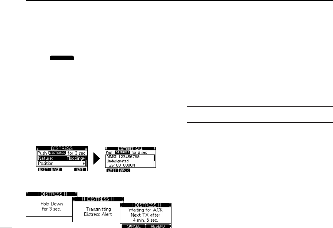
DRegular call
Select the nature of the Distress call to include in the
Regular Distress call.
1. Push
DISTRESS
.
• The Distress Call screen is displayed.
2. Push [ENT] to enter the Nature selection mode.
3. Push[▲],[▼],orrotate[DIAL]toselectthenatureof
thecall,thenpush[ENT].(Example:Flooding)
• Theconrmationscreenisdisplayed.
LIfnovalidGPSdataisbeingreceived,push[▲],[▼],or
rotate [DIAL] to select “Position,” then enter the latitude,
longitude, and UTC.
L See “Entering the position and time” for details.”
4. Whileliftingupthekeycover,holddown[DISTRESS]
(theredbutton)for3secondsuntilyouhear3short
countdownbeepsandalongbeepsound.
• The backlight blinks.
5. Aftersending,waitforanAcknowledgementcall.
• “Waiting for ACK” is displayed.
L The Distress call is automatically sent every 3.5 to 4.5
minutes,untilanAcknowledgementisreceived,ora
Distress Cancel call is sent.
LWhenanAcknowledgementisreceived,analarmsounds.
6. PushanysoftwarekeytoturnOFFthealarm.
• Channel 16 is automatically selected.
7. Holddown[PTT]tocommunicate.
TIP:YoucanalsosendaRegularcallbyselectingthe
“Compose Distress” item on the Menu screen.

23
DSC OPERATION 7
New2001
1
2
3
4
5
6
7
8
9
10
11
12
13
14
15
16
DDistress Cancel call
If you have accidently made a Distress call, or made an
incorrect Distress call, send a Distress Cancel call to
cancelthecallassoonaspossiblewhilewaitingforan
Acknowledgementcall,andreportthepurposeofthe
cancellation.
1. WhilewaitingforanAcknowledgementcall,push
CANCEL
.
• Thescreenbelowisdisplayed.
2. Push
CONTINUE
.
• The Distress Cancel call is sent.
• Channel 16 is automatically selected.
3. Holddown[PTT]toreportthepurposeofthe
cancellation.
LYoucandisplaythewordingofthecancellationbypushing
[▼].
4. After communicating, push
FINISH
.
• The screen to the right is displayed.
5. Push
OK
to finish the Distress Cancel call.
• Returns to the operating screen.
DDistress call software key description
While waiting for an Acknowledgement:
[CANCEL]: Cancels the Distress call and enables you to
sendaCancelcall.(Seetherightcolumn)
[RESEND]: Enables you to resend the Distress call by
holdingdown[DISTRESS]again.
[PAUSE]: Pausesthecountdowntoresendthenext
Distress call.
[INFO]: Displays the information of the Distress call
that you have sent.
After receiving an Acknowledgement:
[EXIT]: Closes the Distress operation, and returns to
the operating screen.
[HIST]: Displays the “Distress History.”
[INFO]: Displays the information of the received
DistressAcknowledgement.
NOTE (For USA and Export versions):
After sending a Distress call without position data
• WhilewaitingforanAcknowledgement,ifvalidpositiondatais
received,thetransceiverwillautomaticallysendaDistresscall
again.
• EvenafterexitingtheDSCmode,ifvalidpositiondata
isreceivedwithin20minutesafterreceivingaDistress
Acknowledgement,thetransceiverwillautomaticallysenda
Distress call again.

24
7DSC OPERATION
New2001
■DSC Settings
On the “DSC Settings” screen, you can make settings on
the DSC call related items.
Position Input
See “Entering the position and time” for details.
Individual ID
See “Entering an Individual ID” for details.
Group ID
See “Entering a Group ID” for details.
Auto ACK
The Auto ACK function automatically sends an
Acknowledgementcallwhenthefollowingcallsarereceived.
• Individualcall(Default:Differsdependingontheversion)
• PositionRequestcall(Default:Manual)
• PollingRequestcall(Default:Auto)
• Testcall(Default:Auto)
Manual:ManuallysendanAcknowledgementcall.
Auto: AutomaticallysendanAcknowledgementcall.
CH Auto Switch (Default:Accept)
Selectwhetherornottoautomaticallyswitchtochannel
16orthespeciedchannel,orselectwhethertoswitchor
ignore the call.
Accept:AfterreceivingaDSCcall,thetransceiverremains
on the operating channel for 10 seconds. After
that,thetransceiverautomaticallyswitchestothe
channelthatisspeciedontheDSCcall.
Ignore: AfterreceivingaDSCcall,ifyoudonotpushthe
softwarekeybelow[ACPT]in10seconds,the
transceiver ignores the call, and then remains on
the current operating channel.
Manual:AfterreceivingaDSCcall,youcanselectwhether
or not to accept the received DSC call.
TIP: When “Auto” is set to the Individual call, the
Acknowledgement“UnabletoComply”isautomaticallysentwhen
the call is received.

25
DSC OPERATION 7
New2001
1
2
3
4
5
6
7
8
9
10
11
12
13
14
15
16
DSC Data Output (Default:Off)
Select an option for the DSC Data Output function.
When receiving a DSC call, this function makes the
transceiver send the call from its NMEA 0183 Output port to
anexternaldevice.
L You can send Distress calls despite of this setting.
OFF: DoesnotsendanycallfromtheNMEA0183
Output port.
All Stations: Sendsthecallfromanyvessel.
Stations List:SendsthecallfromanyvesselontheDSC
individual and group lists.
Alarm Status
Set the alarm ON or OFF for each DSC related item.
•Safety(Default:On)
AnalarmsoundswhenaSafetyDSCcallisreceived.
• Routine(Default:On)
AnalarmsoundswhenaRoutineDSCcallisreceived.
• Warning(Default:On)
Analarmsoundswhen:
- no MMSI code is entered.
- the position data has not been received for 2 minutes
after turning ON the transceiver.
■DSCSettings(Continued)
- the received position data has not been updated for 10
minutes.
- the received position data or manually entered position
data has not been updated for 4 hours.
• Self-Terminate(Default:On)
AnalarmsoundswhenduplicateDistresscallsare
received.
• Discrete(Default:On)
Analarmsoundswhenalowerprioritycallisreceived
whilereceivingahighprioritycall.
CH 70 SQL Level (Default:5)
AdjusttheSquelchlevelforChannel70tobetween1and
10, or Open.
L“”isdisplayedwhenadjustedtoOpen.
Ahigherlevelblocksweaksignals,whichenablesyouto
send a DSC call.

26
7DSC OPERATION
New2001
Self- Test
The Self-Test sends DSC signals to the receiving AF circuit
to compare the sending and receiving signals at the AF
level.
zPush [ENT] to start the Self Test.
L When the sending and receiving DSC signals match, “OK” is
displayed.
Procedure (Default:Single)
(ForonlytheUSAversion,dependingonthepresetting.)
You can select the type of task for the transceiver.
Single: Handlesonly1taskatthesametime.
Multiple: Handlesupto7tasksatthesametime.Youcan
make one or more than 2 DSC calls in parallel.
27
New2001
1
2
3
4
5
6
7
8
9
10
11
12
13
14
15
16
8
MENU SCREEN
■Using the Menu screen
The Menu screen is used to set items, select options, and
so on for the transceiver’s functions.
DUsing the Menu screen
Example: Setting the channel group to “INT.”
1. Push [MENU].
• The Menu screen is displayed.
2. Push[▲],[▼],orrotate[DIAL]toselect“Radio
Settings,” and then push [ENT].
• The“RadioSettings”screenisdisplayed.
LHoldingdown[▲]or[▼]sequentiallyscrollsupordownthrough
the Menu screen.
3. Push[▲],[▼],orrotate[DIAL]toselect“Channel
Group,” then push [ENT].
• The“CHANNELGROUP”screenisdisplayed.
4. Push[▲],[▼],orrotate[DIAL]toselect“INT,”then
push [ENT].
L “INT” is set and the transceiver returns to the previous screen.
TIP:
L To exit the Menu screen, push
EXIT
or [MENU].
L To return to the previous screen, push
BACK
or[CLR].

28
8MENUSCREEN
New2001
*May not be displayed, depending on the transceiver version.
DMenu screen items
The Menu screen contains the following items.
See the refered pages for each items.
Distress (Chapter7)
Item Item
Undesignated
Sinking
Fire,Explosion
Adrift
Flooding AbandoningShip
Collision Piracy
Grounding ManOverboard
Capsizing —
Other DSC (Chapter7)
Item Item
Type Mode
Address Channel
Category
GPS
Conguration
Item Item
Backlight UTCOffset
DisplayContrast Inactivity Timer
Key Beep GPS*
KeyAssignment —
DSC Log (Chapter7)
Item Item
Received Transmitted
Radio Settings
Item Item
Scan Type* WXAlert*
Scan Timer* FAVSettings
Dual/Tri-watch* FAVOnMIC
ChannelGroup CHDisplay*
CallChannel CHClose-up
DSC Settings
Item Item
Position Input DataOutput
IndividualID AlarmStatus
GroupID CH70SQLLevel
AutoACK Self-Test
CHAutoSwitch Procedure
Radio Info

29
MENUSCREEN 8
New2001
1
2
3
4
5
6
7
8
9
10
11
12
13
14
15
16
■Menu items description
DConguration
Backlight (Default:7)
You can adjust the backlight brightness between 1 and 7, or
OFF.
DisplayContrast (Default:4)
Youcanadjustthedisplaycontrastlevelbetween1(lowest)
and7(highest).
KeyBeep (Default:On)
You can select whether or not to sound a beep when a key
is pushed.
• On: Sounds a beep when a key is pushed.
• Off: No beep sounds, for silent operation.
KeyAssignment
Softkey1~16
You can change which software key functions to display, and
their order. You can assign up to 16 software keys at a time.
L The usable software key functions and their order may differ,
depending on the transceiver version or presetting.
SetDefault
Sets the software key function order as default.
L The default setting may differ, depending on the transceiver
version or presetting.
UTC Offset (Default:00:00)
SettheoffsettimebetweenUniversalTimeCoordinated
(UTC)andyourlocaltimetobetween–14:00and+14:00(in
1minutesteps).
InactivityTimer
The transceiver automatically returns to the operation screen
if you push no key for the set period of time for each mode.
Not DSC (Default:10min)
SettingforwhenascreenthatisnotrelatedtoDSCis
displayed.
DSC (Default:15min)
SettingforwhenascreenthatisrelatedtoDSCis
displayed.
Distress (Default:Off)
SettingforwhenascreenthatisrelatedtoaDistresscallis
displayed.
RT (Default:30sec)
SettingforwhenthetransceiverisintheRadioTelephone
mode.

30
8MENUSCREEN
New2001
GPS
Selects a satellite to be used for GPS (Global Positioning
System)topinpointthegeographiclocationofyour
transceiver anywhere in the world.
L This setting may not be usable, depending on the transceiver
version or presetting.
GPS (Always:On)
TheGPS(GlobalPositioningSystem)ispermanentlysetto
ON.
GLONASS (Default:On)
TurnstheGLONASS(GLObal'nayaNAvigatsionnaya
SputnikovayaSistema)functionONorOFF.
SBAS (Default:Off)
TurnstheSBAS(SatelliteBasedAugmentationSystem)
functionONorOFF.
TheSBAStransmitssignalstocorrecterrors,andimproves
accuracy and reliability in data received from regular
GNSSsatellites.WhenthisfunctionisON,youcanusethe
corrected data.
DRadioSettings
ScanType (Default:—)
The transceiver has 2 scan types. Select Normal Scan and
Priority Scan.
• Normal Scan: Scans all Favorite channels in the selected
channel group.
• Priority Scan:SequentiallyscansallFavoritechannels,
whilemonitoringChannel16.
L The default setting differs, depending on the transceiver version.
ScanTimer (Default:Off)
YoucanusetheScanTimertopause,ortoresumeafter5
seconds, when a signal is detected.
• On: When a signal is detected on a channel, the scan
pausesfor5seconds,andthenresumes.Ifthe
signaldisappearsinlessthan5seconds,thescan
immediately resumes.
• Off: When a signal is detected on a channel, the scan
pauses until the signal disappears, and then resumes.
Dual/Tri-watch (Default:Dualwatch)
SelectDualwatchorTri-watch.
• Dualwatch: MonitorsChannel16whilereceivingon
another channel.
• Tri-watch: MonitorsChannel16andtheCallchannel
while receiving on another channel.

31
MENUSCREEN 8
New2001
1
2
3
4
5
6
7
8
9
10
11
12
13
14
15
16
ChannelGroup
Select the suitable channel group for your operating area.
SelectINT,USA,CAN,DSC,orATISdependingonthe
transceiver version.
CallChancel
YoucanchangeyourCallchannel.Thedefaultsetting
differs, depending on the transceiver version.
WXAlert (Default:Off)
FortheUSAandAustralianversions,anNOAAbroadcast
stationtransmitsaWeatherAlerttonebeforeanyimportant
weather information.
L“WX ” is displayed instead of “WX.”
L “WX ” blinks until you push a key after detecting an alert.
• On W/ SC: The preset Weather channels are
sequentiallycheckedwhilescanning.
• On:
Thepreviouslyselected(lastused)Weather
channel is checked while scanning.
• Off: TheWeatherAlerttoneisnotdetected.
FAVSettings
You can set all channels as Favorite channels, clear all
settings, or reset to default. By default, some channels
are preset. The Favorite channels differ, depending on the
transceiver version.
• Set All Channels:
Sets all channels as Favorite channels.
• Clear All Channels:ClearsallFavoritechannels.
• Set Default: ResetsFavoritechannelstothe
default.
FAVonMIC (Default:Off)
Youcanselectthechannelsetwhenyoupush[▲]or[▼]on
the supplied microphone.
• On: Scrolls through only the Favorite channels.
• Off: Scrolls through all the channels.

32
8MENUSCREEN
New2001
CHDisplay
You can select
the number of digits to display the channel
number.
• 3 Digits: The channel number is displayed in 3 digits
suchas“01A
.
”
• 4 Digits: The channel number is displayed in 4 digits
suchas“1001
.
”
L This setting may not be usable, depending on the transceiver
version or presetting.
CHClose-up
You can select whether or not to display the channel name
when changing the operating channel.
• On: The channel number and the channel name are
brieydisplayedwhenchangingthechannel.
• Off: The channel name is not displayed on the screen.
DRadioInfo
Displaysyourtransceiver'sMMSI,Softwareversion,and
GPSversionifbuilt-in.
33
New2001
1
2
3
4
5
6
7
8
9
10
11
12
13
14
15
16
9
CONNECTIONS AND MAINTENANCE
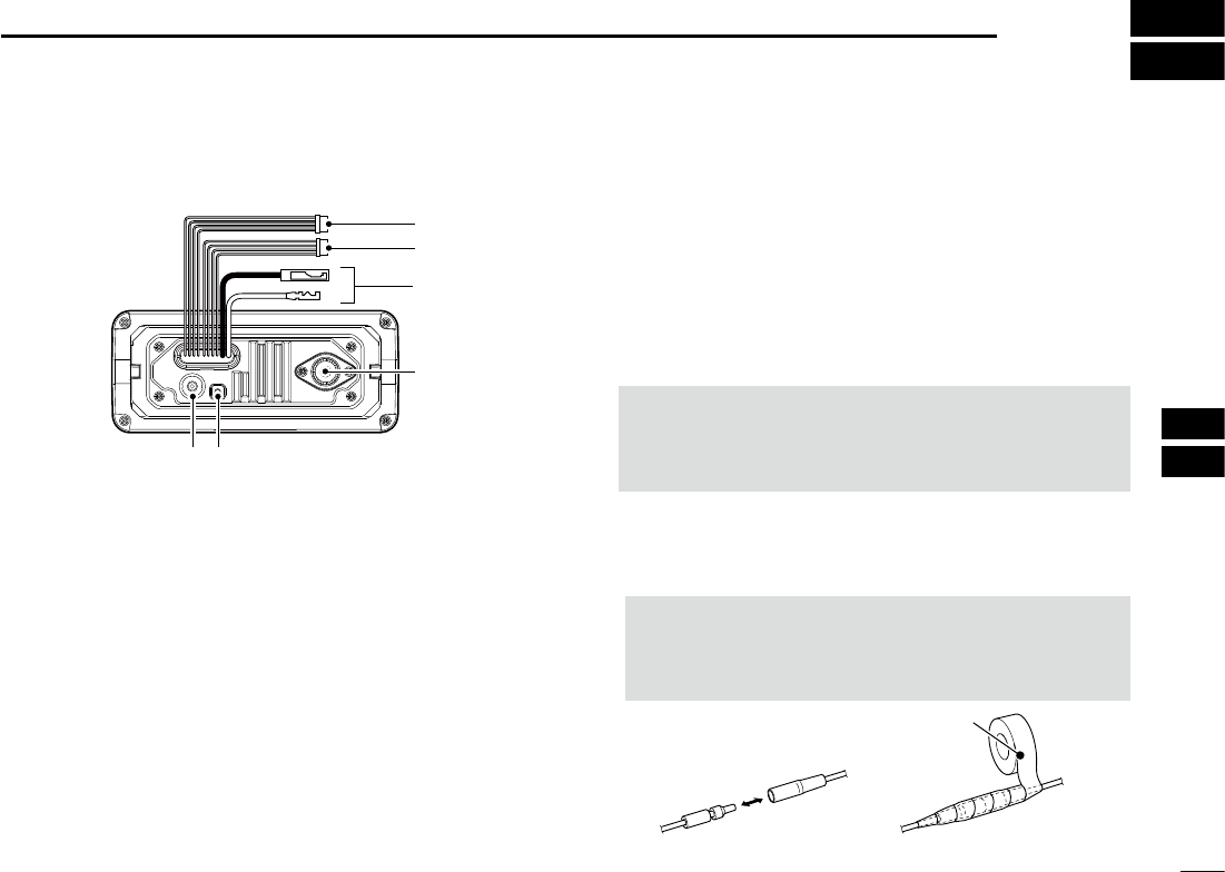
■Connections
w
q
r
ty
e
1NMEA IN/OUT LEADS
Brown: Talker B (Data-L), Data Out (–)
White: Talker A (Data-H), Data Out (+)
Connects to NMEA 0183 In lines of navigation
equipment, to receive position data from other ships.
• An NMEA 0183 (ver. 2.0 or later) sentence format DSC or DSE
compatible navigation equipment is required.
• The built-in GPS outputs RMC, GSA, GSV format sentences.
Green: Listener B (Data-L), GPS In (–)
Yellow: Listener A (Data-H), GPS In (+)
Connects to NMEA Out lines of a GPS receiver for
position data.
• NMEA 0183 (ver. 2.0 or later) sentence format RMC, GGA,
GNS, or GLL and VTG compatible GPS receiver is required.
Ask your dealer about suitable GPS receivers.
• The GPS sentences input from an external GPS receiver have
priority over the sentences from the built-in GPS.
2AF OUT LEADS
Blue: External Speaker (+)
Black: External Speaker (–)
Connects to an external speaker.
Orange: Data line
Gray: Data line
Used only for maintenance purpose.
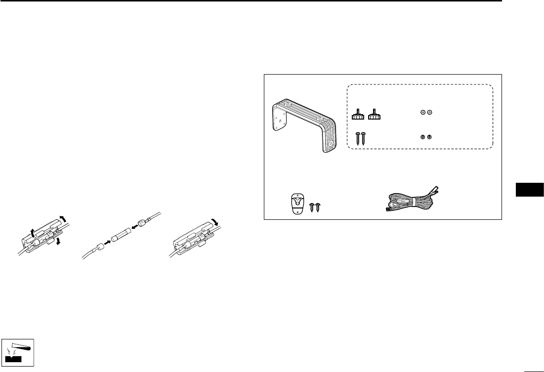
NOTE for NMEA In/Out and AF Out leads:
The connectors are attached to keep the leads together.
Before connecting to a piece of equipment, cut the
leads to remove the connector.
3DC POWER CONNECTOR
Connects to a 13.8 V DC power source.
(+: Red, –: Black)
CAUTION: After connecting the DC power cable,
NMEA leads or external speaker leads cover the
connector and leads with a vulcanizing tape, as shown
below, to prevent water seeping into the connection.
Rubber vulcanzing tape

34
9CONNECTIONS AND MAINTENANCE
New2001
CAUTION: Transmitting without an antenna may
damage the transceiver.
t GROUND TERMINAL
Connects to a vessel ground to prevent electrical shocks
and interference from other equipment occurring.
Use a PH M3 × 6 screw (user supplied).
4ANTENNA CONNECTOR
Connects to a marine VHF antenna with a PL-259
connector. DConnecting the MA-500TR
Connect the transceiver to the high-density D-Sub 15-pin
connector of the MA-500TR using the OPC-2014* cable.
After connecting, you can send an Individual DSC call to
an AIS target using the transponder without entering the
target’s MMSI code.
* The OPC-2014 is supplied with the MA-500TR
• Listener A (Data-H) lead (Yellow):
Connects to lead 3 of the OPC-2014.
• Listener B (Data-L) lead (Green):
Connects to lead 2 of the OPC-2014.
• Talker A (Data-H) lead (White):
Connects to lead 5 of the OPC-2014.
• Talker B (Data-L) lead (Brown):
Connects to lead 4 of the OPC-2014.
35
CONNECTIONS AND MAINTENANCE 9
New2001
1
2
3
4
5
6
7
8
9
10
11
12
13
14
15
16
■Antenna
A key element in the performance of any communication
system is the antenna. Ask your dealer about antennas and
the best place to mount them.
■Fuse replacement
One fuse is installed in the supplied DC power cable. If
the fuse blows or the transceiver stops functioning, track
down the source of the problem, repair it, and replace the
damaged fuse with a new one of the proper rating.
Fuse rating: 10 A
■Cleaning
If the transceiver becomes dusty or dirty, wipe it clean with a
soft, dry cloth.
DO NOT use harsh solvents such as Benzine or
alcohol, as they will damage the transceiver’s
surfaces.
■Supplied accessories
Mounting bracket For mounting bracket
DC power cable Microphone hanger
and screws (3×16 mm)
Knob bolts
Screws (5×20 mm)
Flat washers (M5)
Spring washers (M5)
36
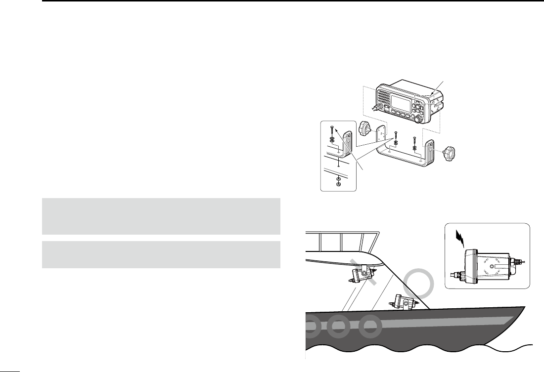
9CONNECTIONS AND MAINTENANCE
New2001
■Mounting the transceiver
DUsing the supplied mounting bracket
You can mount the transceiver on a dashboard using the
universal mounting bracket supplied with your transceiver.
1. Mount the bracket securely to a surface that is more
than 10 mm thick and can support more than 5 kg using
the 2 supplied screws (5 × 20 mm).
2. Attach the transceiver to the bracket so that the face
of the transceiver is at 90° to your line of sight when
operating it.
CAUTION: KEEP the transceiver and microphone at least
1 m (3.3 ft) away from the vessel’s magnetic navigation
compass.
NOTE: Check the installation angle. The function display
may not be easy to read at some angles.
NOTE for the IC-M330G and IC-M330GE:
Built-in GPS receiver is located at the right top of the front
panel.
If the transceiver is covered with any object that interrupts
the GPS signals from the satellites, the GPS receiver will
not calculate its position.
Therefore, when you use the built-in GPS receiver, be sure
the transceiver is positioned so the GPS receiver has a clear
view to receive signals from satellites.
Mounting Example
Built-in GPS receiver is
located here.
(For only the IC-M330G
and IC-M330GE)
User supplied bolts
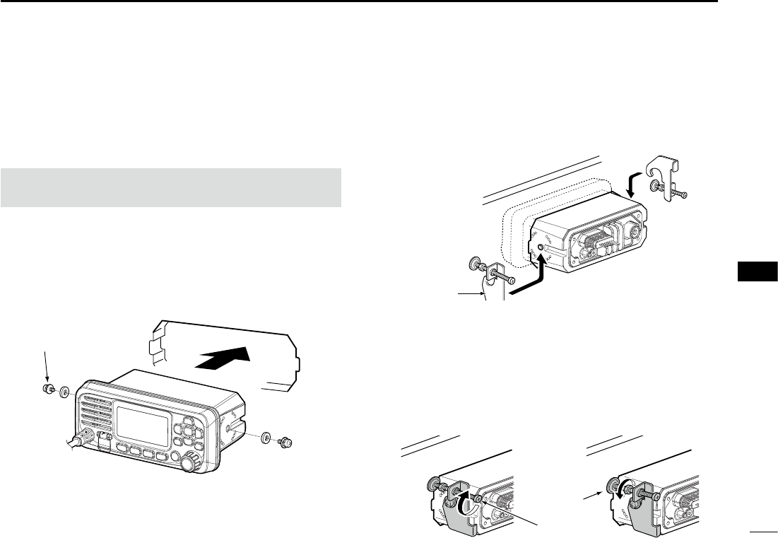
37
CONNECTIONS AND MAINTENANCE 9
New2001
1
2
3
4
5
6
7
8
9
10
11
12
13
14
15
16
■MBF-5 installation
An optional MBF-5 flush mount kit is available for
mounting the transceiver to a at surface (less than 20 mm
thick), such as an instrument panel.
1. Using the template on page ??, carefully cut a hole into
the instrument panel, or wherever you plan to mount
the transceiver.
2. Attach the 2 bolts supplied with the MBF-5 on both
sides of the transceiver.
3. Slide the transceiver through the hole, as shown below.
Supplied bolt
KEEP the transceiver and microphone at least 1 meter
away from your vessel’s magnetic navigation compass.
4. Attach the clamps on both sides of the transceiver.
LMake sure that the clamps align parallel to the
transceiver body.
5. Tighten the end bolts on the clamps (rotate clockwise)
so that the clamps press firmly against the inside of the
instrument control panel. (Torque: 0.6 N•m)
6. Tighten the locking nuts (rotate counterclockwise) so
that the transceiver is securely mounted in position, as
shown below.
7. Connect the antenna and power cable, then return the
instrument control panel to its original place.
End bolt
Locking
nut
Clamp

38
New2001
SPECIFICATIONS AND OPTIONS
10
• Spurious emissions:
IC-M330/IC-M330G Less than -70 dBc (High power)
Less than -56 dBc (Low power)
IC-M330E/IC-M330GE Less than 0.25 µW
DReceiver
• Receive system: Double conversion superheterodyne
• Sensitivity:
FM IC-M330/IC-M330G –120 dBm (typical) (12 dB SINAD)
IC-M330E/IC-M330GE
–118 dBm (typical)
(20 dB SINAD CCITT)
DSC (CH70)
IC-M330/IC-M330G –5 dBµ emf (typical) (1% BER)
IC-M330E/IC-M330GE
–4 dBµ emf (typical) (1% BER)
• Squelch sensitivity:
IC-M330/IC-M330G Less than –10 dBµ
IC-M330E/IC-M330GE Less than –2 dBµ emf
• Intermodulation rejection ratio:
FM IC-M330/IC-M330G More than 70 dB
IC-M330E/IC-M330GE
More than 68 dB
DSC (CH70) More than 73 dBµ emf (1% BER)
• Spurious response rejection ratio:
FM More than 70 dB
DSC (CH70) More than 73 dBµ emf (1% BER)
• Adjacent channel selectivity:
FM More than 70 dB
DSC (CH70) More than 73 dBµ emf (1% BER)
• Audio output power:
Internal 2 W
External 4.5Wat10%distortionintoa4Ωload
New2001
Allstatedspecicationsaresubjecttochangewithoutnoticeorobligation.
■Specications
DGeneral
• Frequency coverage:
TX IC-M330/IC-M330G 156.025 ~ 157.425 MHz
IC-M330E/IC-M330GE
156.025 ~ 161.425 MHz
(Depending on the verision)
RX IC-M330/IC-M330G 156.050 ~ 163.275 MHz
IC-M330E/IC-M330GE
156.050 ~ 161.600 MHz
(Depending on the verision)
CH70 156.525 MHz
• Mode: 16K0G3E (FM)
16K0G2B (DSC)
• Channel spacing: 25 kHz
• Operating temperature range
: –20°C to +60°C;
–4ºF to +140ºF
• Current drain (at 13.8 V):
TX high (25 W) 5 A maximum
Maximum audio 1 A maximum
• Power supply requirement: 13.8V DC (10.8 ~ 15.9V)
Frequency stability: ±5 ppm
• Antennaimpedance: 50Ωnominal
• Dimensions (approximately)
(projections not included): 156.5
(W) × 66.5 (H) × 110.1 (D) mm,
6.2 (W) × 2.6 (H) × 4.3 (D) in
• Weight (approximately): 730 g, 1.61 lb
DTransmitter
• Output power: 25 W or 1 W
• Modulation system: Variable reactance frequency
modulation
•
Maximum frequency deviation:
±5 kHz
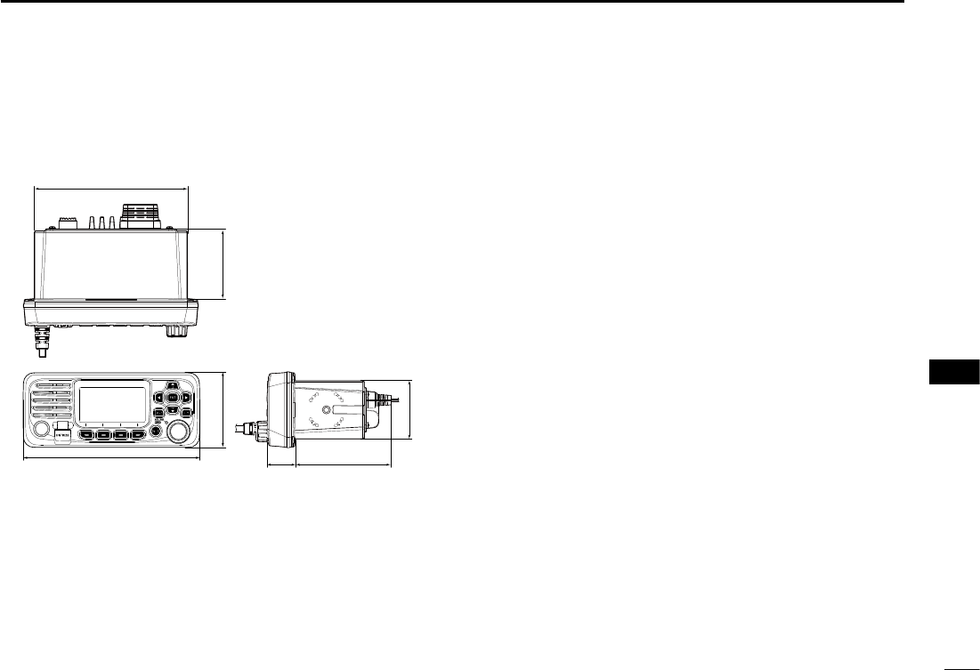
39
SPECIFICATIONS AND OPTIONS 10
New2001
1
2
3
4
5
6
7
8
9
10
11
12
13
14
15
16
New2001New2001New2001
■Options
• MBF-5 flush mount kit
To mount the transceiver to a panel.
•MA-500TR class b ais transponder
To transmit individual DSC calls to a selected AIS target.
DDimensions Unit: mm (inch)
66.5 (2.6)
25.8
(1)
84.3 (3.3)
62.4 (2.5)
137 (5.4)
51 (2)
156.5 (6.2)

1-1-32 Kamiminami, Hirano-ku, Osaka 547-0003, Japan
New2001
A7420-1EX
Printed in Japan
© 2017 Icom Inc.