ICOM orporated AP-12 Wireless Access Point User Manual CERTIFICATE OF COMPLIANCE
ICOM Incorporated Wireless Access Point CERTIFICATE OF COMPLIANCE
UserManual.wiki
>
ICOM orporated
>
AP 12 User Manual
Revised Manual
Navigation menu
Upload a User Manual
Namespaces
Wiki Guide
HTML
PDF
Info
Views
User Manual
Discussion / Help
Navigation

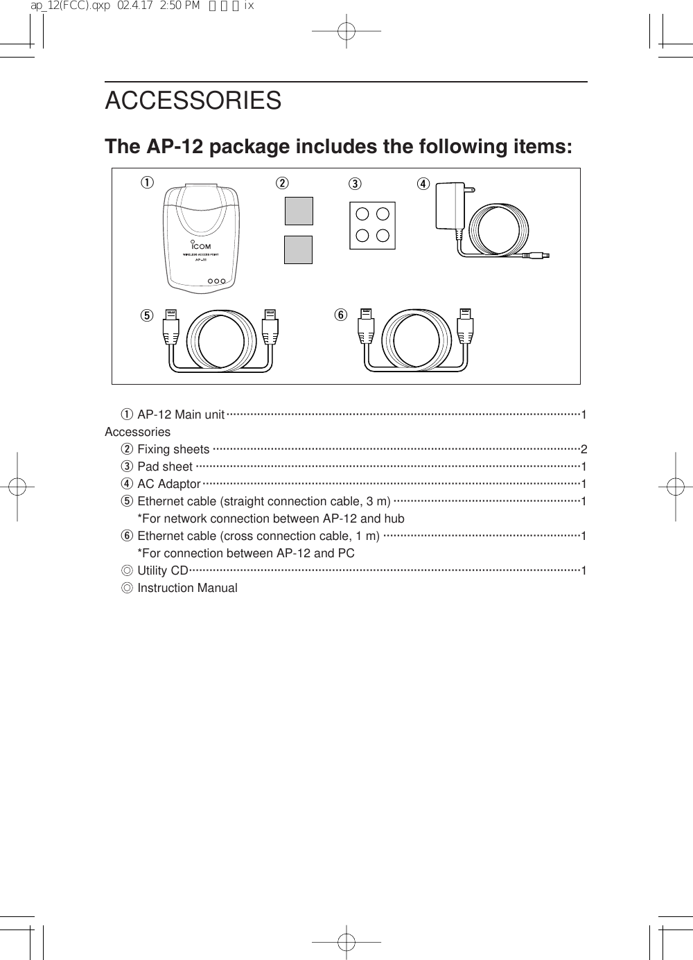
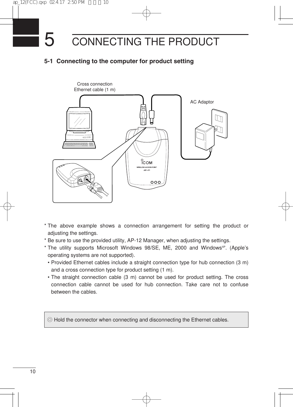
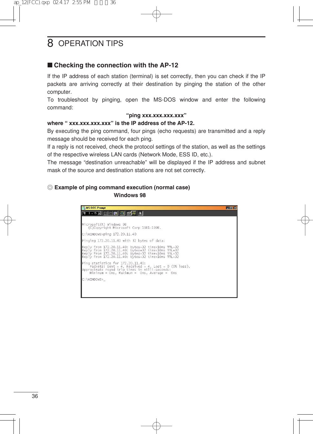
![CONTENTSWireless access point·····························································4Chapter 1 Safety Precautions (Be sure to read these precautions) ——1Chapter 2 General —————————————————————4Chapter 3 Nomenclature ——————————————————6Chapter 4 Installing the Product———————————————7Front and rear panels ·····························································6Installation method and location ·············································7[Installation precautions]·····························································8[Mounting to a shelf] ···································································9[Connection precautions]····························································9Chapter 5 Connecting the Product —————————————105-1 Connecting to the computer for product setting ················105-2 Connecting to a hub ··························································11Chapter 6 Computer Setup ————————————————126-1 Using the setup wizard······················································126-2 Installing the utility software ··············································18Chapter 7 AP-12 Manager —————————————————21Starting the AP-12 Manager ·················································21Connecting an access point··················································22Wireless setting ····································································24IP setting···············································································26Security·················································································27Station list ·············································································29Option ···················································································30About AP-12 Manager ··························································31Chapter 8 Operation Tips —————————————————32Connection to the AP-12 failed·············································32Checking the connection with the AP-12······························36Uninstalling the AP-12 Manager···········································37INTRODUCTIONCONTENTSACCESSORIESap_12(FCC).qxp 02.4.17 2:50 PM ページvii](https://usermanual.wiki/ICOM-orporated/AP-12/User-Guide-238601-Page-7.png)
![24Wireless access point[Infrastructure mode]There are two communication modes forwireless LAN: adhoc mode and infra-structure mode. The adhoc mode meansthat the network consists of wirelessLAN terminals only. This mode allowspear-to-pear communications amongcomputers that are equipped with ICOMwireless LAN card (See the figure shownto the right).The other mode, infrastructure mode,uses a repeater called the access pointsuch as AP-12.The infrastructure mode allows wireless LAN terminals to communicate with each othervia the access point, or with wired LAN terminals via access point at which Ethernetconnection is made. (See the figure shown below).In this mode, a router connected to the wired LAN permits wireless LAN terminals tohave access to the Internet.* Up to 256 wireless terminals can be connected through the AP-12.GENERALSL-1105SL-11 SL-11Wired LANAP-12Wireless Transmission AreaSL-11SL-11HUBEx.: Adhoc mode[Ex.: Infrastructure mode]ap_12(FCC).qxp 02.4.17 2:50 PM ページ4](https://usermanual.wiki/ICOM-orporated/AP-12/User-Guide-238601-Page-13.png)
![52[Multi-channel roaming function]Connecting two or more access points to a wired LAN allows the most suitable accesspoint to be automatically selected depending on the radio communication conditionswhen the wireless terminal is moving.This function will enable you to have access to the network while you are moving in awide area, for example, in a large factory or warehouse.As in the figure below, a standalone access point can also be used for infrastructuremode. This network arrangement, however, disables the multi-channel roaming functioneven if two or more access points are used.GENERALAccess point AWireless terminalHUBAccess point BWired LANHUB[Ex.: Multi-channel roaming]Access pointWireless terminal Wireless terminalWireless terminal[Ex.: Infrastructure mode]2ap_12(FCC).qxp 02.4.17 2:50 PM ページ5](https://usermanual.wiki/ICOM-orporated/AP-12/User-Guide-238601-Page-14.png)
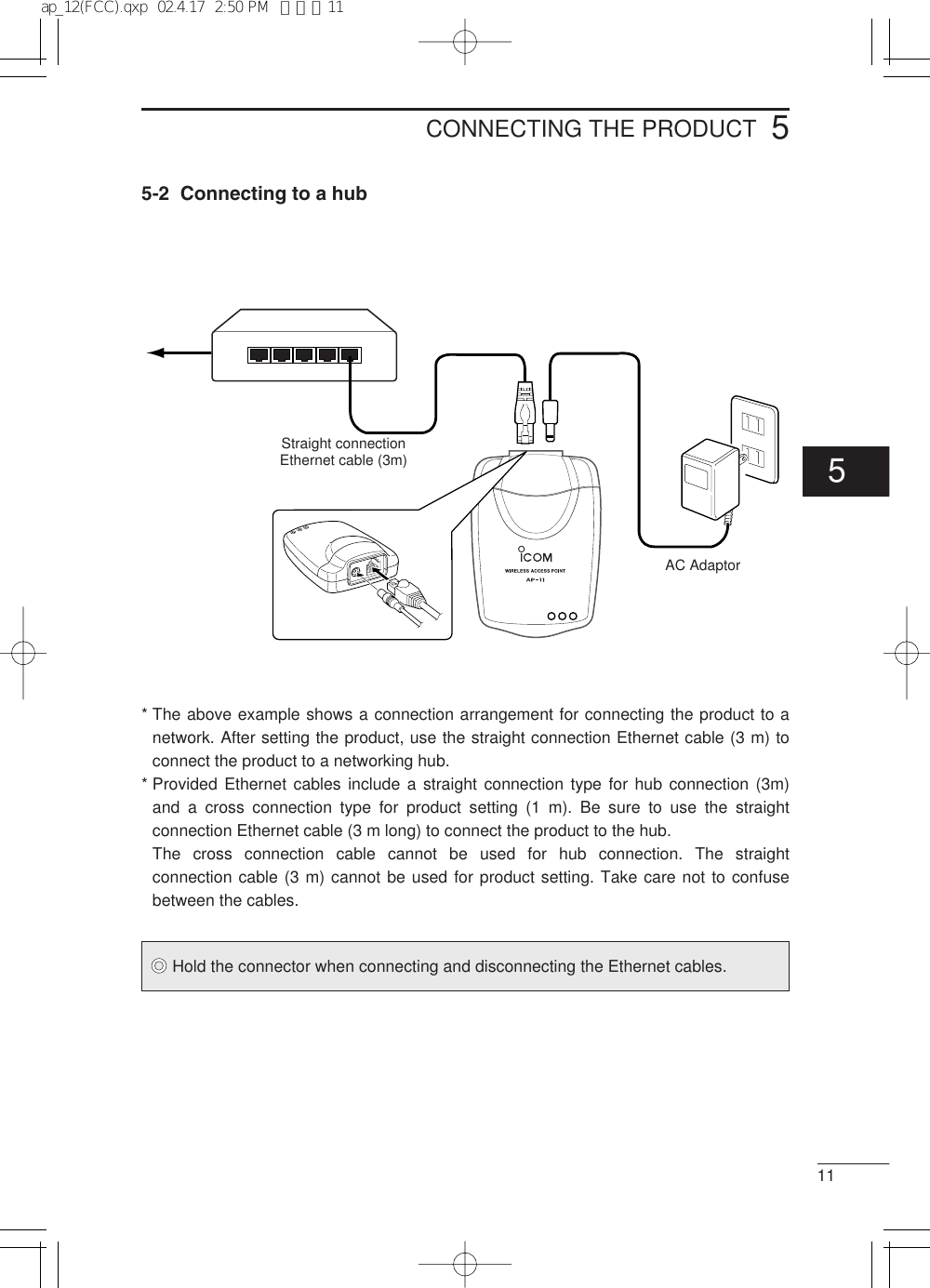
![4INSTALLING THE PRODUCT7Installation method and locationAttach the four rubber cushion pads to all the four corners on the bottom of theproduct to place the product on a flat, level surface, or use the fixing sheets tosecure the product to a wall or shelf. (See the figures below).[Bad installation] (a decrease in transmission speed and range may result)[Good installation]Peel off the protective paper before attaching thesheet.On a desktop PC On a shelfDo not install close to metal obstacles. Do not install in unstable positions.34ap_12(FCC).qxp 02.4.17 2:50 PM ページ7](https://usermanual.wiki/ICOM-orporated/AP-12/User-Guide-238601-Page-16.png)
![4INSTALLING THE PRODUCT8[Installation precautions]The installation site for the wireless access point must be selected carefully inorder to avoid signal interference and reductions in transmission speed andrange.* Select a location with as clear a line of sight as possible (i.e., as high as possible).* Locate the product near the center of the wireless terminal group as far as possible.* Select a stable, level surface that is free of vibrations and the danger of the unit falling.* Others:•Do not place objects on top of the product nor stack products on top of one another.•Do not install the product in a location exposed to intense radio waves (such as neara wireless station) or intense electromagnetic radiation (such as near a radio trans-mission tower).•Floors generally have steel girders and are installed with metal fire protectionmaterial. Consequently, communication between different floors is often not possible.•The transmission range is widest in an open space. However, the signal may bereflected from the large metal walls in such a location as a warehouse.•Radio signals will pass through walls and glass but not through metal. Concrete wallsmay be reinforced with steel or other metal material that will block the signal.•Use the straight connection Ethernet cable (3 m long) to connect the product to a hub.Note that the cross connection Ethernet cable (1 m long) cannot be used for theconnection to a hub.•If the provided straight connection cable is insufficient in length, use a straightconnection cable commercially available.[Transmission range]The transmission range varies somewhat depending on the installation location. Use theline-of-sight distances indicated below as guidelines when using our wireless LAN card(unit) SL-11.When transmission speed is 11 MbpsIndoors: approx. 30map_12(FCC).qxp 02.4.17 2:50 PM ページ8](https://usermanual.wiki/ICOM-orporated/AP-12/User-Guide-238601-Page-17.png)
![94[Mounting to a shelf]Even if the product is correctly secured with thefixing sheets, there is the possibility that theproduct will fall or the DC cord or Ethernetcable will disjoin from the product connectorsdue to the weight of the cables or because ofpeople coming into contact with the cables.When mounting the product high on a shelf,wall or the like, secure it with a commerciallyavailable fasteners or ties to prevent theproduct from falling.[Connection precautions]Before installing the product and setting up the computer, read the followinginstructions carefully to ensure proper installation and setup.* When setting the product, use a standalone computer or disconnect thecomputer from an existing network.* Do not connect the product to a working network without changing the originalfactory settings.Doing so may cause IP address conflicts or other networkproblems.* Make sure the computer used for setting the product is equipped with an Ethernet card(adapter). If not, install an Ethernet card (adapter) and its driver into the computeraccording to the card instruction manual and check that the card works properly beforeinstalling and setting the product.* The settings utility is stored in the provided CD-ROM. The computer must have beenequipped with or connected to a CD-ROM drive.* Install the driver for the wireless LAN card (unit) into the computer according thecard instruction manual and check that the card works properly before installingand setting the product.* Be sure to set the operation mode of all wireless terminals to “Infrastructure” beforeinstalling and setting the product.* Assign the same values for ESS ID and WEP key of the product as those of thewireless terminals that communicate with each other via the product. Failure todo so will does not permit the product to communicate with the wirelessterminals.INSTALLING THE PRODUCT4ap_12(FCC).qxp 02.4.17 2:50 PM ページ9](https://usermanual.wiki/ICOM-orporated/AP-12/User-Guide-238601-Page-18.png)
![612COMPUTER SETUP6-1 Using the setup wizardThe IP address (TCP/IP) must be changed to allow connection of the product to thecomputer before setting the product. The Quick Setup Wizard contained in the providedutility CD will make it easy to change the IP address.[Before starting the quick setup wizard]Connect the product to the computer using the cross connection Ethernet cable (1 m).Plug the AC adaptor cable in the DC jack of the product and connect the AC adaptor tothe wall outlet.• The POWER LED on the front panel of the product will illuminate.[Starting the quick setup wizard and setting the IP address]1. Close all applications that are running on the computer.2. Insert the utility CD into the CD-ROM drive.3. The Auto Run will be activated and the main menuwill appear on the screen.* If Auto Run is not activated, click <Start> and select“Run”. Enter “D:\AP-12\AutoRun.exe” in the commandline box (when the CD is in drive D) and click <OK>.4. Click “Quick Setup Wizard”.The message “Welcome to AP-12 setup wizard” willappear on the screen.5. Click <Next>.* Instead of clicking <Next>, you may press the N key while holding down the Alt key.121212121212ap_12(FCC).qxp 02.4.17 2:51 PM ページ12](https://usermanual.wiki/ICOM-orporated/AP-12/User-Guide-238601-Page-21.png)
![6COMPUTER SETUP13[Starting the quick setup wizard and setting the IP address] (continued)6. Click <Next> to search for the AP-12.7. Select the access point you want to set and then click <Next>.* If the current IP address of the computer does not permit connection to the product, thewindow shown in step 9 will appear on the screen. In this case, set the IP addressaccording to steps 9 and later.• If the current IP address permits connection to the product, the window shown in step14 will appear on the screen. In this case, skip steps 9 to 13 and proceed to step 14.* The IP address of the product is factory set to 192.168.0.1 and the subnet mask to255.255.255.0.Accordingly, if the IP address of the computer has been set to, e.g., 192.168.0.10 andthe subnet mask to 255.255.255.0, allowing connection to the product, the windowsshown in step 9 will not appear and the display will go to the window shown in step 14.Continue setting according to the instructions in the window displayed.12121212126ap_12(FCC).qxp 02.4.17 2:51 PM ページ13](https://usermanual.wiki/ICOM-orporated/AP-12/User-Guide-238601-Page-22.png)
![146COMPUTER SETUP[Starting the quick setup wizard and setting the IP address] (continued)8. If the computer cannot establish connection with the product, you will see the windowthat allows adjustment of the IP address. Set a unique IP address for the computerand click <Next>.* The IP address of the product is factory set to“192.168.0.1”. Enter a value otherthan ”1” in the address box.* The following description assumes that the IP address setting of the computer is“172.20.11.1” and the subnet mask setting is “255.255.0.0”.9. Select “Restart now” and click <Finish>.* The computer will restart.ap_12(FCC).qxp 02.4.17 2:51 PM ページ14](https://usermanual.wiki/ICOM-orporated/AP-12/User-Guide-238601-Page-23.png)
![156COMPUTER SETUP[Starting the quick setup wizard and setting the IP address] (continued)10. The setup wizard will restart automatically.* If the setup wizard does not restart automatically, start the wizard according to step 3.Click <Next>.11. Click <Next>.12. Select the access point you selected in step 8 and click <Next>.12121212121212126ap_12(FCC).qxp 02.4.17 2:52 PM ページ15](https://usermanual.wiki/ICOM-orporated/AP-12/User-Guide-238601-Page-24.png)
![166COMPUTER SETUP[Starting the quick setup wizard and setting the IP address] (continued)13. Set the IP address and subnet mask of the product to the same as those of thecomputer. Note that the IP address must be unique within the network.• In this example, the IP address is set to 172.20.11.4 and the subnet mask to255.255.0.0. Click <Next>.14. Enter an ESS ID. In this example, the default ID (LG) is used. Click <Next>.15. Select a communication channel. In this example, the default channel (11) is used.Click <Next>.121212ap_12(FCC).qxp 02.4.17 2:52 PM ページ16](https://usermanual.wiki/ICOM-orporated/AP-12/User-Guide-238601-Page-25.png)
![176COMPUTER SETUP[Starting the quick setup wizard and setting the IP address] (continued)16. Click <Next>.17. Click <Finish>.18. When the message “Restart computer now?” appears on the screen, click Yes.* If the computer can be connected to the product in step 8, this message will notappear on the screen. In this case, the computer does not need to be restarted.19. The computer will restart.• The setting of the IP address and subnet mask is now complete. You can use theAP-12 Manager to connect the computer to the product.• If you want to use advanced security functions or adjust the IP address and subnetmask of the product, use the utility software, AP-12 Manager. See chapter 7 fordetails.121212[Note]The setup wizard program is not loaded into the computer. When using thewizard, start it from the CD.The setup wizard and the AP-12 Manger (see chapter 7) cannot be run simul-taneously. When starting the setup wizard, be sure to quit the AP-12 Manager inadvance. (For details on how to quit the AP-12 Manager, see page 21).6ap_12(FCC).qxp 02.4.17 2:52 PM ページ17](https://usermanual.wiki/ICOM-orporated/AP-12/User-Guide-238601-Page-26.png)
![1866-2 Installing the utility softwareThis section describes how to install the settings utility, AP-12 Manager.[Before installing the utility]Connect the product to the computer using the cross connection Ethernet cable. Plug theAC adaptor cable in the DC jack of the product and connect the AC adaptor to the walloutlet.• The POWER LED on the front panel of the product will illuminate.[Installing the utility software]1. Close all applications that are running on the computer.2. Insert the utility CD into the CD-ROM drive.3. The Auto Run will be activated and the main menuwill appear on the screen.* If Auto Run is not activated, click <Start> and select“Run”. Enter “D:\AP-12\AutoRun.exe” in the commandline box (when the CD is in drive D) and click<OK>.4. Click “Utility Install”. Click <Next>.5. Click <Next>.1212COMPUTER SETUP121212ap_12(FCC).qxp 02.4.17 2:53 PM ページ18](https://usermanual.wiki/ICOM-orporated/AP-12/User-Guide-238601-Page-27.png)
![196COMPUTER SETUP6[Installing the utility software] (continued)6. Click <Next>.7. Specify the folder in which you want to install the utility and click <Next>.* If you want to change the default folder that will appear in the text box as shownbelow, click <Browse> and select the desired folder.8. When the message “Create New Folder” appears on the screen, click <OK>.1212Click <Browse>ap_12(FCC).qxp 02.4.17 2:53 PM ページ19](https://usermanual.wiki/ICOM-orporated/AP-12/User-Guide-238601-Page-28.png)
![206[Installing the utility software] (continued)9. Click <Install>.10. Click <Finish>. The installation is now complete.11. Click <Finish> to close the menu.COMPUTER SETUP121212121212[Note]To uninstall the AP-12 Manager, see chapter 8 Operation Tips.ap_12(FCC).qxp 02.4.17 2:53 PM ページ20](https://usermanual.wiki/ICOM-orporated/AP-12/User-Guide-238601-Page-29.png)
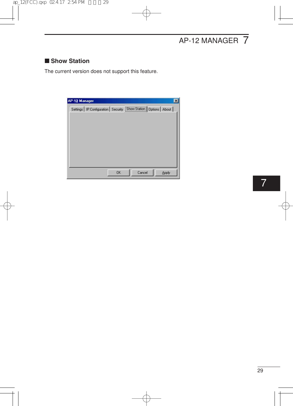
![721Starting the AP-12 ManagerThis section describes how to start and quit the AP-12 Manager installed in thecomputer.[How to start]1. Connect the Ethernet port of the product with the Ethernet adaptor (card) port of thecomputer using the cross connection Ethernet cable (1 m).* Be sure to use the provided cross connection Ethernet cable (1 m).2. Click <Start> and select “AP-12 Manager” from the Program menu. An iconindicating that the AP-12 Manager is running is displayed on the task bar. [How to quit]1. To quit the AP-12 Manager, right-click the AP-12 Manager icon on the task bar andthen select Exit from the pop-up menu that appears.AP-12 MANAGERAP-127ap_12(FCC).qxp 02.4.17 2:53 PM ページ21](https://usermanual.wiki/ICOM-orporated/AP-12/User-Guide-238601-Page-30.png)
![227Connecting an access pointUsing the AP-12 Manager allows you to perform setting required for using the productand advanced WEP-based security setting.[How to connect]Connect the Ethernet port of the product with the Ethernet adaptor (card) port of thecomputer using the cross connection Ethernet cable (1 m).* Product setting with the AP-12 Manager cannot be done unless the ports areconnected.* Do not use the straight connection Ethernet cable (3m) to connect the ports.1. Right-click the AP-12 Manger icon on the task bar. Select “Connect to Access Point”from the pop-up menu that appears.2. Click the “Connect to Access Point” tab.3. Click <Search> on the “Connect to Access Point” tab.AP-12 MANAGERAP-12ap_12(FCC).qxp 02.4.17 2:53 PM ページ22](https://usermanual.wiki/ICOM-orporated/AP-12/User-Guide-238601-Page-31.png)
![237[How to connect] (continued)4. All the available access points and their current addresses will be displayed in theSearch Results box,5. Select the access point you want to access and then click <Connect>.6. The AP-12 Manager setting menu for the selected access point will appear on thescreen.This menu includes the “Setting”, “IP Configuration”, “Security”, “Show Station”,“Option” and “About” tabs.[Error]If the error message “Connection to access point has failed” appear on the screen, theQuick Setup Wizard may have failed in setting the IP address or subnet mask. In such acase, consult chapter 8 Operation Tips to set the IP address and subnet mask of thecomputer manually.AP-12 MANAGER12(AP-12 Manager setting menu)7ap_12(FCC).qxp 02.4.17 2:53 PM ページ23](https://usermanual.wiki/ICOM-orporated/AP-12/User-Guide-238601-Page-32.png)
![257AP-12 MANAGER[Procedure] (continued)Domain nameThis field shows the domain name of the product. The domain name cannot be changed.ChannelThe wireless communication channel is specified in this field. (Default: 11)When multiple access points are used, refer to the following note to set the channels.Communication channelsIf two or mote access points are placed within the wireless transmission area, it isrecommended to set the communication channels of network groups at least fourchannels apart to avoid interference.Otherwise, interference may occur due to partial overlap in bandwidth as shownbelow. Channel settings of 1-6-11, for example, eliminates the possibility of inter-ference.2400 2410 2420 2430 2440 2450Frequency (MHz)2460 2470 24801 channel2 channel3 channel4 channel5 channel6 channel7 channel8 channel9 channel11 channel10 channel7ap_12(FCC).qxp 02.4.17 2:54 PM ページ25](https://usermanual.wiki/ICOM-orporated/AP-12/User-Guide-238601-Page-34.png)
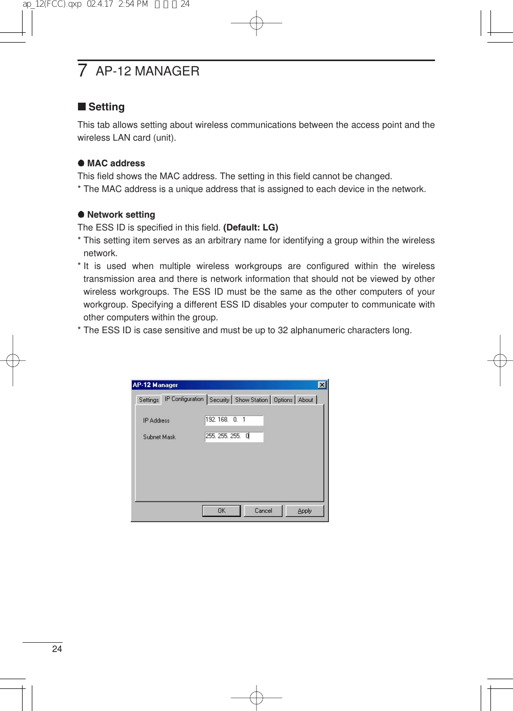
![267AP-12 MANAGERIP ConfigurationSetting the IP address and subnet maskThis tab is used to set the IP address and subnet mask so as to allow the productto be connected to a working network.IP address: Specify the IP address of the product in this field. (Default: 192.168.0.1)Subnet mask: Specify the subnet mask in this field. (Default: 255.255.255.0)[Note]* The AP-12 cannot be used as a DHCP server. This means the IP address and thesubnet mask of the product must be set manually. The IP address of terminals may beassigned automatically depending on the network environment. (See the settingexamples shown below).* The IP address for each computer within a network group must be unique.* The subnet masks of all the computers within a network group must be the same.(IP Address setting examples)The following shows addressing examples where the network comprises threecomputers.AP-12: 192.168.0.40*1(subnet mask: 255.255.255.0)Wireless terminal A: 192.168.0.41*2(subnet mask: 255.255.255.0)Wireless terminal B: 192.168.0.42*2(subnet mask: 255.255.255.0)Wireless terminal C: 192.168.0.43*2(subnet mask: 255.255.255.0)*1: In case a DHCP server automatically assigns IP addresses to other access points, itis recommended to specify the IP address of the product as large as practicable inorder to avoid address collision.*2: If the network contains a DHCP server (such as dialup router) that is capable ofautomatically assigning IP addresses, the server capability may be utilized to assignIP addresses to wireless terminals. In this case, “Obtain an IP address automatically”is selected during computer setup for networking.** For details on network settings, see the instruction manuals for the DHCP serverand wireless terminals.12ap_12(FCC).qxp 02.4.17 2:54 PM ページ26](https://usermanual.wiki/ICOM-orporated/AP-12/User-Guide-238601-Page-35.png)
![277AP-12 MANAGERSecurityThis tab is used to set the degree of WEP (Wired Equivalent Privacy) based encryptionused to protect the data transmitted over the network.Communications is not permitted unless this field setting is the same for all of thecomputers with which you wan to communicate.[Note]* WEP setting should be made for the AP-12 and then for each wireless terminal.WEP enableIf “WEP Enabled” is not selected, no WEP key is usedand therefore no data is encrypted during transmission.Key generatorEnter a character string for generating the key used forencryption and decryption. When a character sting isentered in this field, 4 keys are created automaticallyand displayed in the text boxes.* The same character sting entered in the KeyGenerator field will result in the same WEP keyscreated in the text bopxes.* Selecting a key number in the WEP Key area allows proper reception of encrypteddata.The key is case sensitive and must be up to 30 alphanumeric characters long. Enter thesame key for all of the computers with which you are communicating.* If different character strings are used, the encrypted data cannot be decrypted.* Instead of specifying a key for encryption/decryption, you may enter hexadecimalnumerals directly in the WEP key text boxes. (See “WEP key” on the next page).127ap_12(FCC).qxp 02.4.17 2:54 PM ページ27](https://usermanual.wiki/ICOM-orporated/AP-12/User-Guide-238601-Page-36.png)
![287AP-12 MANAGER[Security] (continued)WEP key• The [WEP key] text boxes contains lower 40 bits (10 hexadecimal numerals) generatedfrom the character string entered in the [Key Generator]box.• Select check box 1, 2, 3 or 4 that you want to use forencryption.• The hexadecimal alphanumerics in the selected text boxare used for encryption. The destination computer cannotdecrypt transmitted data unless it is using the samehexadecimal alphanumerics for decryption.[Customizing the WEP keys]• Instead of entering a key in the Key Generator box, you may enter up to hexadecimalalphanumerics directly in the WEP key text boxes.• When this is done, any character sting in the Key Generator box is ignored.• Enter the same alphanumerics in each text boxes as other terminals in the networkgroup. (See examples 1 and 2).• Otherwise, data communications will fail. (See example 3).• When the Mask option is selected, the contents in the WEP key text boxes aredisplayed as “***”.Bidirectionaltransmission enabledBidirectionaltransmission enabledTransmissiondisabledExample 1Example 3Example 2ap_12(FCC).qxp 02.4.17 2:54 PM ページ28](https://usermanual.wiki/ICOM-orporated/AP-12/User-Guide-238601-Page-37.png)
![307AP-12 MANAGER12Option[General]Display bannerThe banner of the AP-12 Manager can be OFF when theutility starts. (Default: ON)Icon animationThe animated icon on the task bar shows the operation status of the AP-12.This icon animation can be OFF. The icon itself remains on the task bar.(Default: ON)[Security]Set a passwordClicking this check box allows you to set a passwordrequired for starting the AP-12 Manager. Setting a pass-word will provides protection against theft or unauthorizedchanges of access point data or settings. Passwordsshould be changed periodically.• Passwords must be up to 32 characters long, and is case sensitive.• To change passwords, deselect the check box and the click <Apply>.Mask setting dataThe WEP key and key generator data can masked. Masked data is displayed as “***··”.These functions are activated by clicking <Apply>.12ap_12(FCC).qxp 02.4.17 2:54 PM ページ30](https://usermanual.wiki/ICOM-orporated/AP-12/User-Guide-238601-Page-39.png)

![832OPERATION TIPSConnection to the AP-12 failedIf connection to the desired access point failed even though the AP-12 Manager is used,the possible causes include the following:(1) The Ethernet adaptor does not work normally, or (2) The quick setup wizard has failed in setting the IP address.[Note]The following description assumes the 10BASE-T Ethernet card (adaptor) has beeninstalled in the computer. It the Ethernet card (adaptor) has not yet installed in thecomputer, install the card and its driver according to the instruction manual for the card.* The following procedure applies to a Windows 98 machine.Checking the Ethernet adaptorCheck if the Ethernet card (adaptor) in the computer works normally as follows:[Procedure]1. Click <Start> and select “Control Panel” from the “Settings” menu.2. Double-click the “System” icon on the “Control Pane” screen.3. Select the “Device Managers” tab and click “+” for the “Network Adapters” icon.4. Select the “Ethernet Adapter” tab and click <Properties>.If the driver has been installed properly, the window shown on the next page willappear on the screen.* The adaptor name indicated on the screen will vary depending on the adaptor used.ap_12(FCC).qxp 02.4.17 2:55 PM ページ32](https://usermanual.wiki/ICOM-orporated/AP-12/User-Guide-238601-Page-41.png)
![338OPERATION TIPS[Procedure] (continued)* If the “Ethernet adaptor” icon are marked with “!” or “×”, or “Ethernet adaptor” arelocated under “Other Devices”, the installation of the driver unit driver may havefailed.In such a case, uninstall the driver and then install again.5. Make sure “This device is working properly” appears in the “Device status” field onthe “General” tab of the Properties window.Click <OK>. The display will return to the window shown in Step 3.6. Click <OK> on the window shown in step 3.7. If the Ethernet card (adaptor) works normally, proceed to “Manual setting of IPaddress” on the next page.8ap_12(FCC).qxp 02.4.17 2:55 PM ページ33](https://usermanual.wiki/ICOM-orporated/AP-12/User-Guide-238601-Page-42.png)
![348OPERATION TIPSManual setting of the IP addressThis section describes how to set the IP address of the computer without using the setupwizard.[Note]Before setting or changing the IP address manually, note the present address value soas to restore the address to the original value when necessary.[Procedure]1. Click <Start> and select “Control Panel” from the “Settings” menu. Double-click the“Network” icon.2. Make sure “TCP/IP” and “Client for Microsoft Networks” are displayed on the“Network Configuration” tab. If these network components are not displayed on the “Network Configuration” tab,the installation of these components may have failed.* Make sure “Client for Microsoft Networks” is displayed in the “Primary NetworkLogon” field.* Make sure the “TCP/IP –> name of LAN card (adaptor) currently used” is displayedin the “The following network components are installed” field on the “NetworkConfiguration” tab.3. Select “TCP/IP” and click <Properties>.* If multiple network adaptors have been installed, select “TCP/IP –> name of LANcard (adaptor) currently used”. ap_12(FCC).qxp 02.4.17 2:55 PM ページ34](https://usermanual.wiki/ICOM-orporated/AP-12/User-Guide-238601-Page-43.png)
![358OPERATION TIPS[Procedure] (continued)4. Click the “IP Address” tab.5. Select “Specify an IP address” and enter “192.168.0.10” in the “IP Address” field and“255.255.255.0” in the “Subnet Mask” field. Then click <OK>. * The IP address of the product is factory set to 192.168.0.1.6. The display will return to the window shown in step 3. Click <OK>.7. When the message “Restart computer now?” is displayed, click <OK>.After the computer restarts, use the AP-12 Manager to set the product.8ap_12(FCC).qxp 02.4.17 2:55 PM ページ35](https://usermanual.wiki/ICOM-orporated/AP-12/User-Guide-238601-Page-44.png)
![378OPERATION TIPSUninstalling the AP-12 ManagerThis section describes how to uninstall the utility, AP-12 Manager, from a Windows 98machine.When your computer uses an operating system other than Windows 98, follow the on-screen messages or instructions to uninstall the utility.[Procedure]1. Click <Start> and select “Control Panel” from the “Settings” menu. Double-click“Add/Remove Programs”.2. Select “AP-12 Manager” and click <Add/Remove>.3. The AP-12 Manager Uninstall Wizard will start. Click <Uninstall>.121212128ap_12(FCC).qxp 02.4.17 2:55 PM ページ37](https://usermanual.wiki/ICOM-orporated/AP-12/User-Guide-238601-Page-46.png)
![938SETTING EXAMPLESNetwork arrangementThis chapter shows IP address setting examples for the following network arrangement.This network consists of the product (ICOM access point AP-12), wireless ISDN Router,wireless LAN card SL-11 and wired and wireless terminals (PCs).HUBAP-12Wireless Transmission AreaPC-2PC-3(SL-11) PC-1InternetRouter[Router settings]IP address: 192.168.0.1Subnet mask: 255.255.255.0DHCP server function: EnableInitial allocation IP address: 192.168.0.10Number of allocations: 30[PC1 (Desktop PC)]* An Ethernet card is required.The IP address of this terminal isassigned by the DHCP server function of the Router automatically. Select“TCP/IP”from the installed network com-ponents on the “Network Configuration”tab and click <Properties>; and thenselect “Obtain an IP address automati-cally”.* For setting items not shown here, seethe instruction manuals for respectivedevices.[AP-12 settings (manual)]Channel: 11IP address: 192.168.0.40Subnet mask: 255.255.255.0* The value subsequent to the last dotshould be set to “40” or more. Otherwise,the IP address may collide with an IPaddress that is automatically assigned bythe Router.[PC3 (SL-11)*1]IP address: 192.168.0.42*2Subnet mask: 255.255.255.0*2*1 Operation mode: Infrastructure*2 If the network contains a DHCP server,the “Obtain an IP address automatically”option can be selected.*ESS ID and WEP-related settings mustbe the same between the AP-12 andeach wireless terminal (PC2, PC3).ap_12(FCC).qxp 02.4.17 2:55 PM ページ38](https://usermanual.wiki/ICOM-orporated/AP-12/User-Guide-238601-Page-47.png)
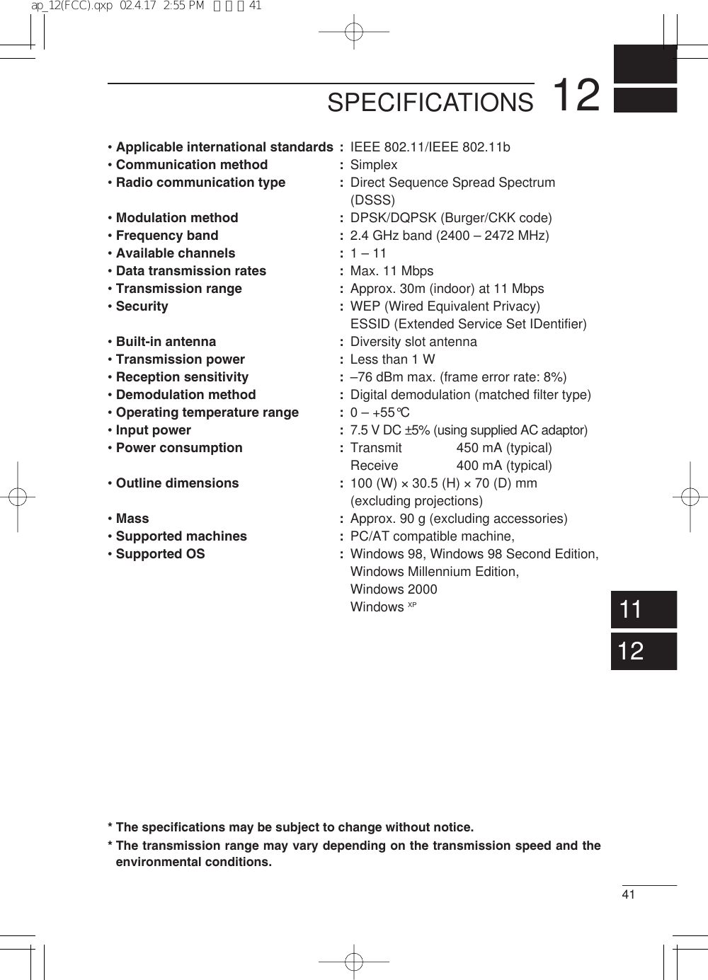
![10REFERENCE3910-1 Default Setting ValuesThe original factory setting values are listed below for each AP-12 setting window.[Wireless setting]• ESS ID: LG (alphanumeric characters, upper case)• Channel: 11[IP setting]• IP address: 192.168.0.1• Subnet mask: 255.255.255.0[Security]• WEP security: Disable• Key generator: Non[Option]• Display banner: ON• Icon animation: ON• Password protection: OFF• Setting data mask: OFF10-2 Function List• Wireless access point function• Wireless roaming function• Wireless security(ESS ID, WEP)10-3 Ethernet portType RJ-45 8-pin modular jack: 11. Send (+)2. Send (–)3. Receive (+)4. Not used5. Not used6. Receive (–)7. Not used8. Not used12345678910ap_12(FCC).qxp 02.4.17 2:55 PM ページ39](https://usermanual.wiki/ICOM-orporated/AP-12/User-Guide-238601-Page-48.png)