ICOM orporated AP-12 Wireless Access Point User Manual CERTIFICATE OF COMPLIANCE
ICOM Incorporated Wireless Access Point CERTIFICATE OF COMPLIANCE
Revised Manual

360 Herndon Parkway, Suite 1400 Work Order number 2001326
Herndon, VA 20170 FCC Part 15.247
http://www.rheintech.com Industry Canada RSS-210
FCC ID AFJAP-12
M/N AP-12
© Rhein Tech Laboratories, Inc. Page 49 of 63
APPENDIX J: MANUAL
Please see the following pages.
INSTRUCTION MANUAL
WIRELESS ACCESS POINT
AP-12
CONTENTS
1 SAFETY PRECAUTIONS
2 GENERAL
3 NOMENCLATURE
4 INSTALLING THE PRODUCT
5 CONNECTING THE PRODUCT
6 COMPUTER SETUP
7 AP-12 MANAGER
8 OPERATION TIPS
9 SETTING EXAMPLES
10 REFERENCE
11 AFTER SERVICE
12 SPECIFICATIONS
13 TERMINOLOGY
ap_12(FCC).qxp 02.4.17 2:50 PM ページi
ap_12(FCC).qxp 02.4.17 2:50 PM ページiii

INTRODUCTION
INTRODUCTION
CAUTION:
Changes or modifications not expressly approved by Icom Inc. could
void the user’s authority to operate this Access Point.
Class B digital device users;
This equipment has been tested and found to comply with the limits for a Class B
digital device, pursuant to Part 15 of the FCC Rules. These limits are designed to
provide reasonable protection against harmful interference in a residential
installation. This equipment generates, uses, and can radiate radio frequency
energy and, if not installed and used in accordance with the instruction manual,
may cause harmful interference to radio communications. However, there is no
guarantee that interference will not occur in a particular installation. If this
equipment does cause harmful interference to radio or television reception, which
can be determined by turning the equipment off and on, the user is encouraged to
try to correct the interference by one or more of the following measures:
• Reorient or relocate the receiving antenna.
• Increase the separation between the equipment and receiver.
• Connect the equipment into an outlet on a circuit different from that to which the receiver
is connected.
• Consult the dealer or an experienced radio/TV technician for help.
RF EXPOSURE SAFETY INFORMATION:
CAUTION: To comply with the FCC RF exposure requirements, this transmitter (built-
in antenna) must be installed with a separation distance of least 8 inches
(20cm) from all persons and must not be co-located or operating in conjuction with
any other antenna or transmitter.
For CANADA only
Operation is subject to the following two conditions: (1) this device may not cause
interference, and (2) this device must accept any interference, including interference
that may cause undesired operation of the device.
ABOUT WIRELESS COMMUNICATION CHANNELS
The wireless communication channel for the unit is referred to as “the DS Channel”
(see page 25).
AP-12
Tested to comply
with FCC standards
FOR HOME OR OFFICE USE
FCC INFORMATION
ap_12(FCC).qxp 02.4.17 2:50 PM ページiv

INTRODUCTION
Thank you for purchasing an ICOM wireless access point.
This wireless access point is provided with the functions necessary for
supporting a wireless LAN.
This manual is designed to help you use the product to its fullest
potential. Read this manual carefully before using the product.
FEATURES OF THE PRODUCT
""All settings can be adjusted using the provided utility program, AP-12 Manager.
""Up to 256 wireless terminals can be connected through the product.
""Windows 98/SE, ME, 2000 and WindowsXP are supported.
""Networks combining wireless LAN and wired LAN components can be constructed
with ease.
""The roaming function is provided in addition to the wireless access point function.
""11-Mbps wireless access point communications and 10BASE-T wired LAN communi-
cations are allowed.
""Applicable ICOM wireless LAN cards include the following: (As of March 2002)
SL-11
""Security in communications is ensured by ESS ID settings and WEP encryption.
TRADEMARK CREDITS
Icom, Icom Inc. and the logo are registered trademarks of Icom Incorporated
(Japan) in the United states, the United Kingdom, Germany, France, Spain, Russia
and/or other countries.Windows is a registered trademark of Microsoft Corporation in the
United States and/or other countries.
The screen shots that appear in this manual are used with permission of Microsoft
Corporation.
Other product and company names mentioned herein are trademarks or registered
trademarks of their respective owners.
ap_12(FCC).qxp 02.4.17 2:50 PM ページv

INTRODUCTION
INTRODUCTION
GENERAL PRECAUTIONS
™™Observe the instructions provided in the manuals included with the computer and
other peripheral devices.
™™This device may cause signal interference when used in a domestic setting.
When interference occurs, move this unit as far as possible away from the
affected device.
™™The LAN unit drivers and the settings utility supplied with this unit are dedicated
to the unit. Do not use them for other devices
™™Icom Inc. assumes no responsibility whatsoever for any damages or lost profits
resulting from opportunities for voice or signal communications being missed
because of the modifications, disassembly, failure, malfunctions, defects or data
loss of the LAN unit, or because of such external causes as power failure; nor will
Icom Inc. assume any responsibility for demands made by a third party.
™™All copyrights associated with this manual and all intellectual property rights
associated with the hardware and software of this product are held by Icom Inc.
™™Unauthorized reproduction or transmission of this manual, or any part hereof, is
prohibited.
™™The content of this manual, the hardware and software associated with this
product, and the appearance of this product are all subject to change without
notice.
ap_12(FCC).qxp 02.4.17 2:50 PM ページvi

CONTENTS
Wireless access point·····························································4
Chapter 1 Safety Precautions (Be sure to read these precautions) ——1
Chapter 2 General —————————————————————4
Chapter 3 Nomenclature ——————————————————6
Chapter 4 Installing the Product———————————————7
Front and rear panels ·····························································6
Installation method and location ·············································7
[Installation precautions]·····························································8
[Mounting to a shelf] ···································································9
[Connection precautions]····························································9
Chapter 5 Connecting the Product —————————————10
5-1 Connecting to the computer for product setting ················10
5-2 Connecting to a hub ··························································11
Chapter 6 Computer Setup ————————————————12
6-1 Using the setup wizard······················································12
6-2 Installing the utility software ··············································18
Chapter 7 AP-12 Manager —————————————————21
Starting the AP-12 Manager ·················································21
Connecting an access point··················································22
Wireless setting ····································································24
IP setting···············································································26
Security·················································································27
Station list ·············································································29
Option ···················································································30
About AP-12 Manager ··························································31
Chapter 8 Operation Tips —————————————————32
Connection to the AP-12 failed·············································32
Checking the connection with the AP-12······························36
Uninstalling the AP-12 Manager···········································37
INTRODUCTION
CONTENTS
ACCESSORIES
ap_12(FCC).qxp 02.4.17 2:50 PM ページvii

CONTENTS
CONTENTS
Chapter 10 Reference ———————————————————39
Chapter 11 After Service ——————————————————40
Chapter 12 Specifications —————————————————41
Chapter 13 Terminology ——————————————————42
Chapter 9 Setting Examples ————————————————38
When the product fails··························································40
10-1 Default Setting Values·····················································39
10-2 Function List····································································39
10-3 Ethernet port····································································39
General·················································································41
ap_12(FCC).qxp 02.4.17 2:50 PM ページviii
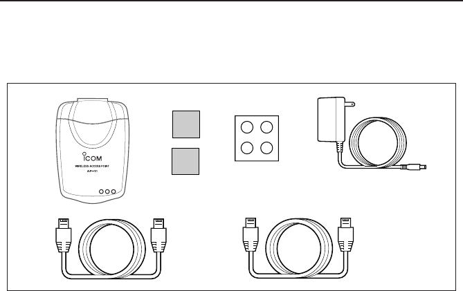
ACCESSORIES
The AP-12 package includes the following items:
qAP-12 Main unit········································································································1
Accessories
wFixing sheets ············································································································2
ePad sheet ·················································································································1
rAC Adaptor···············································································································1
tEthernet cable (straight connection cable, 3 m) ·······················································1
*For network connection between AP-12 and hub
yEthernet cable (cross connection cable, 1 m) ··························································1
*For connection between AP-12 and PC
""Utility CD···················································································································1
""Instruction Manual
qr
w
ty
e
ap_12(FCC).qxp 02.4.17 2:50 PM ページix
1
SAFETY PRECAUTIONS
1
1
Be sure to read these precautions in order to use the
wireless access point safely.
* These precautions are intended to ensure that the access point is operated
safely and correctly. Follow these instructions to avoid property damage and
prevent personal injury to yourself (user) or others in the vicinity.
* Before reading the rest of this manual, read and understand the precautions
listed under “RWarning” and “RCaution” below.
* After reading this manual, store it in a convenient place for future review.
Wireless Access Point
Do not use any AC adapter other than
the one provided with this product.
Otherwise fire, electric shock, or
equipment failure may result.
Use only the specified parts and
accessories.
Otherwise fire, electric shock, or
equipment failure may result.
Do not connect the power supply to
any terminal other than the DC jack.
Otherwise fire, electric shock, or
equipment failure may result.
Do not modify, excessively bend,
twist, pull, or heat the connecting
cables.
Otherwise the cables may be damaged
and cause a fire, electric shock, or
equipment failure.
Do not place heavy objects on top of
the connecting cables or allow the
cables to be pinched.
Otherwise the cables may be damaged
and cause a fire, electric shock, or
equipment failure.
Install and use in a location where
children cannot reach the power cord
and cables.
Pulled cables could result in electric
shock or personal injury.
This unit does not require adjustment.
Do not disassemble or modify the unit
or attempt to repair it yourself.
Otherwise fire, electric shock, or
equipment failure may result.
Do not install in a location where the
unit can easily become wet (such as
adjacent to a humidifier).
Otherwise fire, electric shock, or
equipment failure may result.
Do not handle the unit with wet hands.
Otherwise electric shock may result.
Discontinue use immediately and
unplug the power cable from the AC
receptacle if the unit emits smoke, an
abnormal odor, or an abnormal noise
or if water enters the unit.
Otherwise fire, electric shock, or
equipment failure may result.
Disconnect the plug of the AC adapter
and all other cables from the unit.
Confirm that the smoke, odor, or noise
stops and contact your dealer or the
service staff at one of our sales offices.
Failure to observe the precautions listed here could
result in serious or fatal injury to the user or those
near the user.
RRWARNING
ap_12(FCC).qxp 02.4.17 2:50 PM ページ1
1
2
SAFETY PRECAUTIONS
Do not install the unit outdoors.
Otherwise equipment failure may result.
Do not place on a slanted or unstable
surface.
Otherwise the unit may tilt over or fall,
resulting in personal injury or equipment
failure.
Avoid installing in humid, dusty, or
poorly ventilated locations.
Otherwise equipment failure may result.
Do not use in locations exposed to
direct sunlight, close to heating or
cooling ducts, or otherwise subject to
severe fluctuations in temperature.
Otherwise the unit may become
deformed or discolored. Also, fire or
equipment failure may result.
Be sure to connect the cables
correctly as explained in this manual.
Do not use any other connection
arrangement.
Otherwise equipment failure may result.
Avoid locations exposed to strong
magnetic fields or static electricity
and locations exposed to
temperatures or humidity levels that
exceed the specifications listed in the
manual.
Otherwise equipment failure may result.
Do not use close to radios or
televisions.
Otherwise signal interference may occur.
Do not drop or the unit or otherwise
subject it to strong physical shock.
Otherwise personal injury or equipment
failure may result.
Do not stand, sit, or place heavy
objects on the unit. Do not pinch the
unit.
Otherwise the unit may be damaged.
When thunder and/or lightning occur
nearby, disconnect the AC adapter
from the wall socket and do not use
the unit. Also, discontinue such work
as connecting cables, disconnecting
cables, installation, or maintenance.
Otherwise fire or electric shock may
result.
Do not use in locations where
condensation is likely to occur. Avoid
hastily moving the unit to a location
where the humidity level is very
different because condensation may
occur.
Otherwise the unit may become
deformed or discolored. Also, fire or
equipment failure may result.
If condensation occurs, dry the unit or
allow the unit to remain in the same
environment until it is completely dry
before using.
Disconnect the AC adapter from the
unit when the unit will not be used for
a long time.
Otherwise the unit may become hot and
fire or equipment failure may result.
Do not clean with paint thinner or
benzene.
Otherwise the case material may
degrade or the paint may peel. Clean
with a soft cloth. When particularly dirty,
dampen the cloth slightly with a neutral
cleaning agent that has been diluted with
water.
Failure to observe the precautions listed here could
result in personal injury or property damage.
RCAUTION
ap_12(FCC).qxp 02.4.17 2:50 PM ページ2
1
3
SAFETY PRECAUTIONS
1
General Precautions
The unit may malfunction if the connecting cables become disconnected or the connection
is unstable while the unit is in operation. Be sure all connectors are securely fastened and
do not touch them while the unit is in operation.
Observe the instructions provided in the manuals included with the computer and other
peripheral devices.
This device may cause signal interference when used in a domestic setting. When
interference occurs, move this unit as far as possible away from the affected device.
The disks entitled “Utility Software” (utility for updating the firmware) is specifically
intended for this unit. Do not use the disks with any other device.
ICOM Inc. assumes no responsibility whatsoever for any trouble resulting from using the
data files originally provided with this unit or the firmware update data files provided on
our web site in a device other than this unit, or modifying or disassembling this unit. Nor
does ICOM Inc. assume any responsibility whatsoever for any damages or lost profits
resulting from opportunities for voice or signal communications being lost because of the
failure, malfunction, poor condition, damage, or data loss of this unit or because of such
external causes as power failure. ICOM also dismisses all responsibility for demands
made by a third party.
All copyrights associated with this manual and all intellectual property rights associated
with the hardware and software of this product are held by ICOM Inc.
Unauthorized reproduction or transmission of this manual, or any part hereof, is
prohibited.
The content of this manual, the hardware and software associated with this product, and
the appearance of this product are all subject to change without notice.
Do not use with an AC supply voltage
other than 230V
Otherwise fire, electric shock, or
equipment failure may result.
Do not use with any device other than
the AP-12.
Otherwise fire, electric shock, or
equipment failure may result.
Do not modify, excessively bend,
twist, pull, or heat the AC power cord.
Otherwise the cord may be damaged
and cause a fire, electric shock, or
equipment failure.
Do not place heavy objects on top of
the DC output cord or allow the cord
to be pinched.
Otherwise the cord may be damaged
and cause a fire, electric shock, or
equipment failure.
Hold the adapter body when plugging
in and unplugging the AC adapter. Do
not yank the cord.
Otherwise fire, electric shock, or
equipment failure may result.
Do not handle the AC adapter plug or
other devices with wet hands.
Otherwise electric shock may result.
Do not use the AC adapter if the DC
output cord is damaged or the plug
does not fit securely into the
receptacle.
Otherwise fire, electric shock, equipment
failure, or data loss may result.
Consult with your dealer or the service
staff at one of our sales offices regarding
how to handle the problem or obtain a
new AC adapter.
Failure to observe the precautions listed here could
result in serious or fatal injury to the user or those
near the user.
RWARNING
AC adapter
ap_12(FCC).qxp 02.4.17 2:50 PM ページ3
2
4
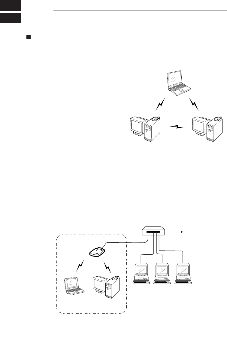
Wireless access point
[Infrastructure mode]
There are two communication modes for
wireless LAN: adhoc mode and infra-
structure mode. The adhoc mode means
that the network consists of wireless
LAN terminals only. This mode allows
pear-to-pear communications among
computers that are equipped with ICOM
wireless LAN card (See the figure shown
to the right).
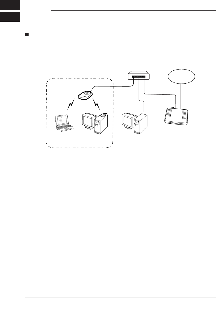
The other mode, infrastructure mode,
uses a repeater called the access point
such as AP-12.
The infrastructure mode allows wireless LAN terminals to communicate with each other
via the access point, or with wired LAN terminals via access point at which Ethernet
connection is made. (See the figure shown below).
In this mode, a router connected to the wired LAN permits wireless LAN terminals to
have access to the Internet.
* Up to 256 wireless terminals can be connected through the AP-12.
GENERAL
SL-1105
SL-11 SL-11
Wired LAN
AP-12
Wireless Transmission Area
SL-11
SL-11
HUB
Ex.: Adhoc mode
[Ex.: Infrastructure mode]
ap_12(FCC).qxp 02.4.17 2:50 PM ページ4
5
2
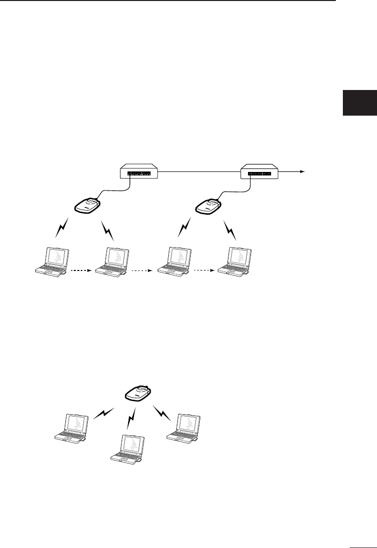
[Multi-channel roaming function]
Connecting two or more access points to a wired LAN allows the most suitable access
point to be automatically selected depending on the radio communication conditions
when the wireless terminal is moving.
This function will enable you to have access to the network while you are moving in a
wide area, for example, in a large factory or warehouse.
As in the figure below, a standalone access point can also be used for infrastructure
mode. This network arrangement, however, disables the multi-channel roaming function
even if two or more access points are used.
GENERAL
Access point A
Wireless terminal
HUB
Access point B
Wired LAN
HUB
[Ex.: Multi-channel roaming]
Access point
Wireless terminal Wireless terminal
Wireless terminal
[Ex.: Infrastructure mode]
2
ap_12(FCC).qxp 02.4.17 2:50 PM ページ5
3
6
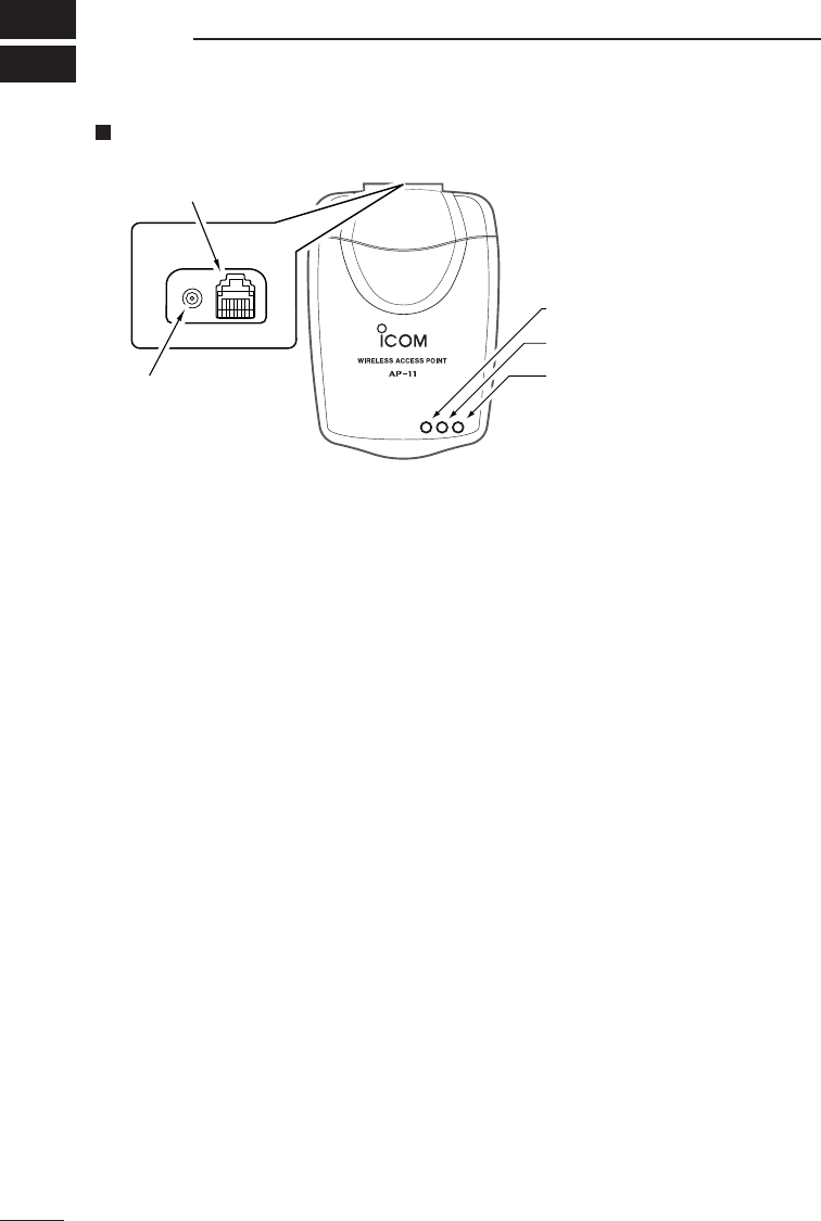
Front and rear panels
qPower LED
This lamp illuminates when the power to the AP-12 is on.
wLAN LED
This lamp illuminates when the wired LAN (Ethernet) connection is normal.
This lamp flashes when the AP-12 is communicating with a wired LAN.
It does not illuminate if the AP-12 does not recognize the Ethernet port connection.
Make sure the LAN cable is connected to the Ethernet port.
eWireless LAN transmission LED
This lamp flashed during data transmission.
rEthernet port
This is an RJ-45 type Ethernet port.
Connect a hub to the AP-12 using the provided Ethernet cable (straight connection
cable).
Connect a computer to the AP-12 unit using the provided Ethernet cable (cross
connection cable). Use the utilities “AP-12 Manager” and “Quick Setup Wizard” to set
up the computer.
* Avoid lower grade Ethernet cables. If a lower grade of cable is used, the grade of
the entire network will be pulled down to the same level.
tDC jack
Connect the provided AC adapter to the AP-12.
NOMENCLATURE
rEthernet port
qPower LED
wLAN LED
eWireless LAN transmission LED
tDC jack
ap_12(FCC).qxp 02.4.17 2:50 PM ページ6
4
INSTALLING THE PRODUCT
7
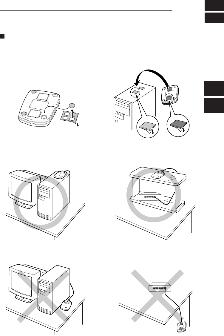
Installation method and location
Attach the four rubber cushion pads to all the four corners on the bottom of the
product to place the product on a flat, level surface, or use the fixing sheets to
secure the product to a wall or shelf. (See the figures below).
[Bad installation] (a decrease in transmission speed and range may result)
[Good installation]
Peel off the protective paper before attaching the
sheet.
On a desktop PC On a shelf
Do not install close to metal obstacles. Do not install in unstable positions.
3
4
ap_12(FCC).qxp 02.4.17 2:50 PM ページ7

4INSTALLING THE PRODUCT
8
[Installation precautions]
The installation site for the wireless access point must be selected carefully in
order to avoid signal interference and reductions in transmission speed and
range.
* Select a location with as clear a line of sight as possible (i.e., as high as possible).
* Locate the product near the center of the wireless terminal group as far as possible.
* Select a stable, level surface that is free of vibrations and the danger of the unit falling.
* Others:
•Do not place objects on top of the product nor stack products on top of one another.
•Do not install the product in a location exposed to intense radio waves (such as near
a wireless station) or intense electromagnetic radiation (such as near a radio trans-
mission tower).
•Floors generally have steel girders and are installed with metal fire protection
material. Consequently, communication between different floors is often not possible.
•The transmission range is widest in an open space. However, the signal may be
reflected from the large metal walls in such a location as a warehouse.
•Radio signals will pass through walls and glass but not through metal. Concrete walls
may be reinforced with steel or other metal material that will block the signal.
•Use the straight connection Ethernet cable (3 m long) to connect the product to a hub.
Note that the cross connection Ethernet cable (1 m long) cannot be used for the
connection to a hub.
•If the provided straight connection cable is insufficient in length, use a straight
connection cable commercially available.
[Transmission range]
The transmission range varies somewhat depending on the installation location. Use the
line-of-sight distances indicated below as guidelines when using our wireless LAN card
(unit) SL-11.
When transmission speed is 11 Mbps
Indoors: approx. 30m
ap_12(FCC).qxp 02.4.17 2:50 PM ページ8
9
4
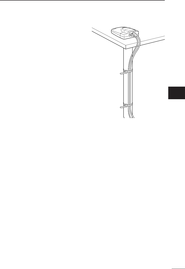
[Mounting to a shelf]
Even if the product is correctly secured with the
fixing sheets, there is the possibility that the
product will fall or the DC cord or Ethernet
cable will disjoin from the product connectors
due to the weight of the cables or because of
people coming into contact with the cables.
When mounting the product high on a shelf,
wall or the like, secure it with a commercially
available fasteners or ties to prevent the
product from falling.
[Connection precautions]
Before installing the product and setting up the computer, read the following
instructions carefully to ensure proper installation and setup.
* When setting the product, use a standalone computer or disconnect the
computer from an existing network.
* Do not connect the product to a working network without changing the original
factory settings.Doing so may cause IP address conflicts or other network
problems.
* Make sure the computer used for setting the product is equipped with an Ethernet card
(adapter). If not, install an Ethernet card (adapter) and its driver into the computer
according to the card instruction manual and check that the card works properly before
installing and setting the product.
* The settings utility is stored in the provided CD-ROM. The computer must have been
equipped with or connected to a CD-ROM drive.
* Install the driver for the wireless LAN card (unit) into the computer according the
card instruction manual and check that the card works properly before installing
and setting the product.
* Be sure to set the operation mode of all wireless terminals to “Infrastructure” before
installing and setting the product.
* Assign the same values for ESS ID and WEP key of the product as those of the
wireless terminals that communicate with each other via the product. Failure to
do so will does not permit the product to communicate with the wireless
terminals.
INSTALLING THE PRODUCT
4
ap_12(FCC).qxp 02.4.17 2:50 PM ページ9
5
10
CONNECTING THE PRODUCT
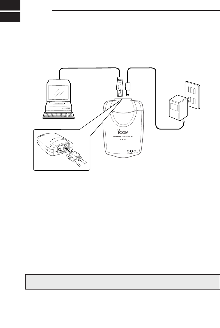
5-1 Connecting to the computer for product setting
* The above example shows a connection arrangement for setting the product or
adjusting the settings.
* Be sure to use the provided utility, AP-12 Manager, when adjusting the settings.
* The utility supports Microsoft Windows 98/SE, ME, 2000 and WindowsXP. (Apple’s
operating systems are not supported).
•Provided Ethernet cables include a straight connection type for hub connection (3 m)
and a cross connection type for product setting (1 m).
•The straight connection cable (3 m) cannot be used for product setting. The cross
connection cable cannot be used for hub connection. Take care not to confuse
between the cables.
""Hold the connector when connecting and disconnecting the Ethernet cables.
Cross connection
Ethernet cable (1 m)
AC Adaptor
ap_12(FCC).qxp 02.4.17 2:50 PM ページ10
11
5
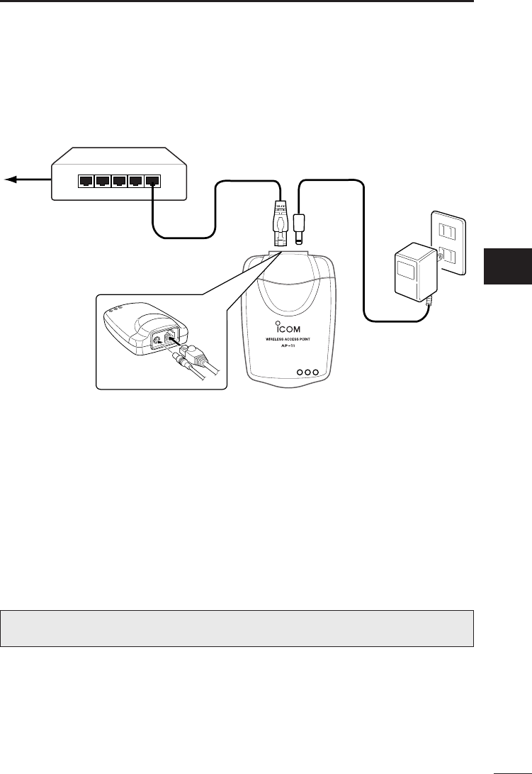
5-2 Connecting to a hub
* The above example shows a connection arrangement for connecting the product to a
network. After setting the product, use the straight connection Ethernet cable (3 m) to
connect the product to a networking hub.
* Provided Ethernet cables include a straight connection type for hub connection (3m)
and a cross connection type for product setting (1 m). Be sure to use the straight
connection Ethernet cable (3 m long) to connect the product to the hub.
The cross connection cable cannot be used for hub connection. The straight
connection cable (3 m) cannot be used for product setting. Take care not to confuse
between the cables.
CONNECTING THE PRODUCT
5
""Hold the connector when connecting and disconnecting the Ethernet cables.
Straight connection
Ethernet cable (3m)
AC Adaptor
ap_12(FCC).qxp 02.4.17 2:50 PM ページ11
6
12
COMPUTER SETUP
6-1 Using the setup wizard
The IP address (TCP/IP) must be changed to allow connection of the product to the
computer before setting the product. The Quick Setup Wizard contained in the provided
utility CD will make it easy to change the IP address.
[Before starting the quick setup wizard]
Connect the product to the computer using the cross connection Ethernet cable (1 m).
Plug the AC adaptor cable in the DC jack of the product and connect the AC adaptor to
the wall outlet.
• The POWER LED on the front panel of the product will illuminate.
[Starting the quick setup wizard and setting the IP address]
1. Close all applications that are running on the computer.
2. Insert the utility CD into the CD-ROM drive.
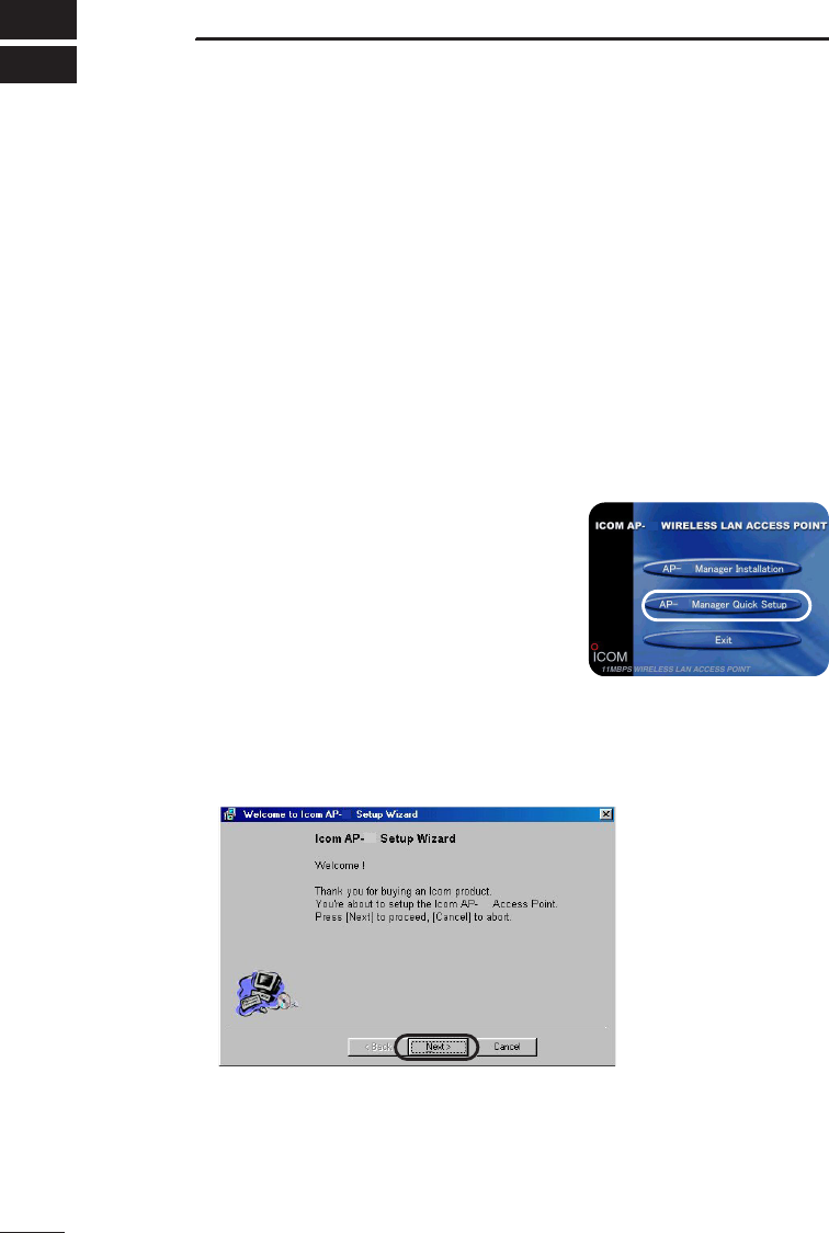
3. The Auto Run will be activated and the main menu
will appear on the screen.
* If Auto Run is not activated, click <Start> and select
“Run”. Enter “D:\AP-12\AutoRun.exe” in the command
line box (when the CD is in drive D) and click <OK>.
4. Click “Quick Setup Wizard”.
The message “Welcome to AP-12 setup wizard” will
appear on the screen.
5. Click <Next>.
* Instead of clicking <Next>, you may press the N key while holding down the Alt key.
12
12
12
12
12
12
ap_12(FCC).qxp 02.4.17 2:51 PM ページ12
6
COMPUTER SETUP
13
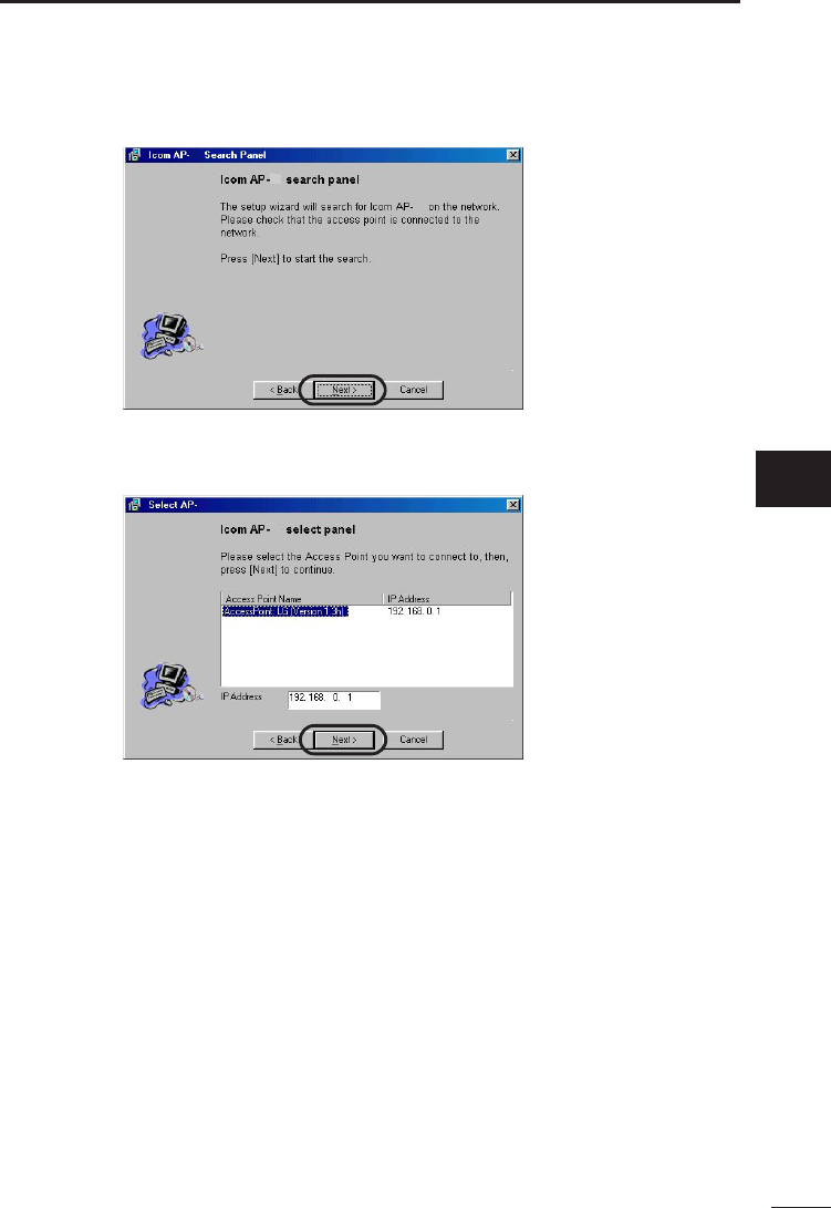
[Starting the quick setup wizard and setting the IP address] (continued)
6. Click <Next> to search for the AP-12.
7. Select the access point you want to set and then click <Next>.
* If the current IP address of the computer does not permit connection to the product, the
window shown in step 9 will appear on the screen. In this case, set the IP address
according to steps 9 and later.
• If the current IP address permits connection to the product, the window shown in step
14 will appear on the screen. In this case, skip steps 9 to 13 and proceed to step 14.
* The IP address of the product is factory set to 192.168.0.1 and the subnet mask to
255.255.255.0.
Accordingly, if the IP address of the computer has been set to, e.g., 192.168.0.10 and
the subnet mask to 255.255.255.0, allowing connection to the product, the windows
shown in step 9 will not appear and the display will go to the window shown in step 14.
Continue setting according to the instructions in the window displayed.
12
12
12
12
12
6
ap_12(FCC).qxp 02.4.17 2:51 PM ページ13
14
6COMPUTER SETUP
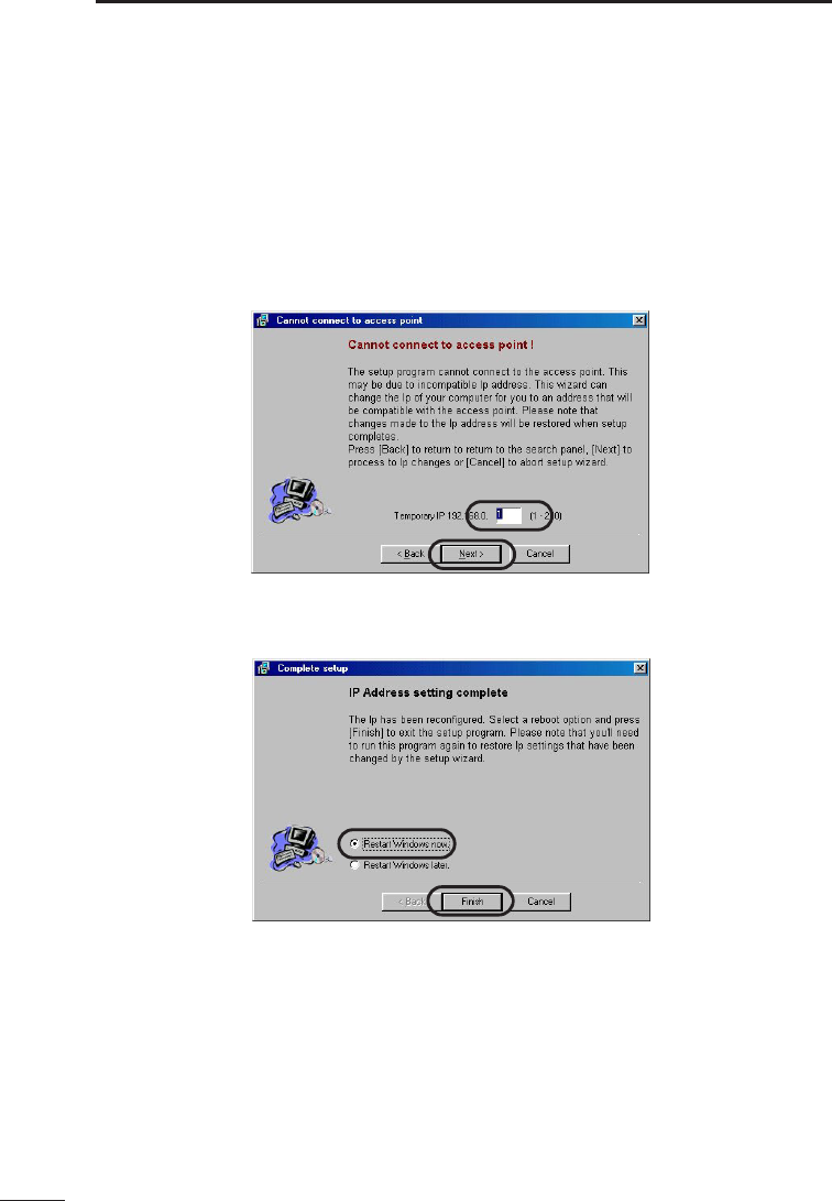
[Starting the quick setup wizard and setting the IP address] (continued)
8. If the computer cannot establish connection with the product, you will see the window
that allows adjustment of the IP address. Set a unique IP address for the computer
and click <Next>.
* The IP address of the product is factory set to“192.168.0.1”. Enter a value other
than ”1” in the address box.
* The following description assumes that the IP address setting of the computer is
“172.20.11.1” and the subnet mask setting is “255.255.0.0”.
9. Select “Restart now” and click <Finish>.
* The computer will restart.
ap_12(FCC).qxp 02.4.17 2:51 PM ページ14
15
6
COMPUTER SETUP
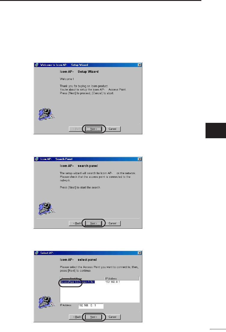
[Starting the quick setup wizard and setting the IP address] (continued)
10. The setup wizard will restart automatically.
* If the setup wizard does not restart automatically, start the wizard according to
step 3.
Click <Next>.
11. Click <Next>.
12. Select the access point you selected in step 8 and click <Next>.
12
12
12
12
12
12
12
12
6
ap_12(FCC).qxp 02.4.17 2:52 PM ページ15
16
6COMPUTER SETUP
[Starting the quick setup wizard and setting the IP address] (continued)
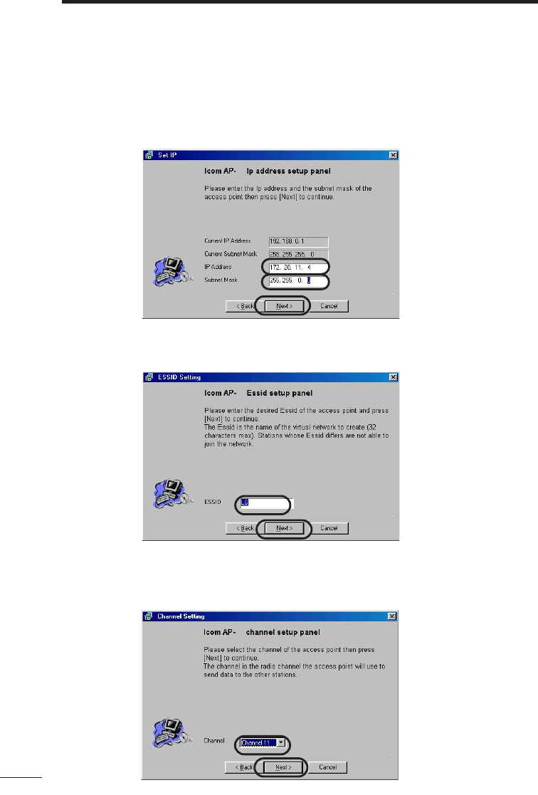
13. Set the IP address and subnet mask of the product to the same as those of the
computer. Note that the IP address must be unique within the network.
• In this example, the IP address is set to 172.20.11.4 and the subnet mask to
255.255.0.0. Click <Next>.
14. Enter an ESS ID. In this example, the default ID (LG) is used. Click <Next>.
15. Select a communication channel. In this example, the default channel (11) is used.
Click <Next>.
12
12
12
ap_12(FCC).qxp 02.4.17 2:52 PM ページ16
17
6
COMPUTER SETUP
[Starting the quick setup wizard and setting the IP address] (continued)
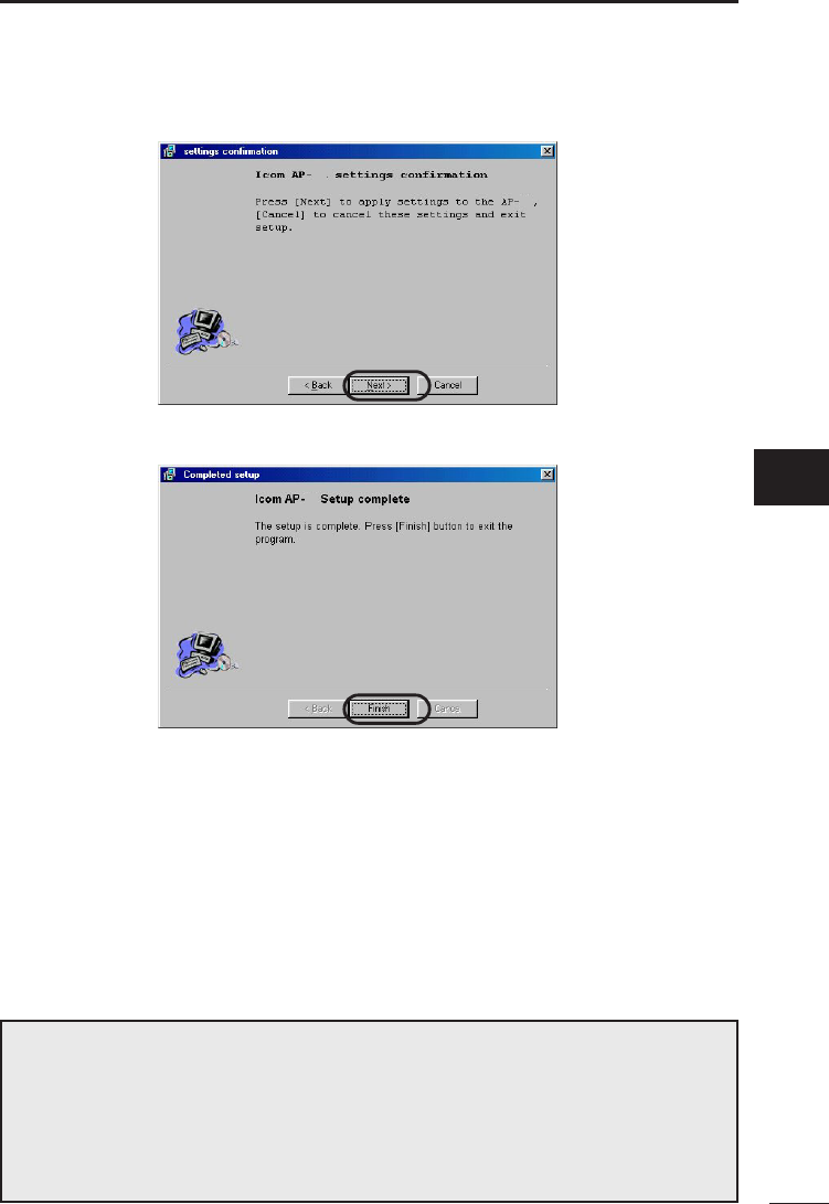
16. Click <Next>.
17. Click <Finish>.
18. When the message “Restart computer now?” appears on the screen, click Yes.
* If the computer can be connected to the product in step 8, this message will not
appear on the screen. In this case, the computer does not need to be restarted.
19. The computer will restart.
• The setting of the IP address and subnet mask is now complete. You can use the
AP-12 Manager to connect the computer to the product.
• If you want to use advanced security functions or adjust the IP address and subnet
mask of the product, use the utility software, AP-12 Manager. See chapter 7 for
details.
12
12
12
[Note]
The setup wizard program is not loaded into the computer. When using the
wizard, start it from the CD.
The setup wizard and the AP-12 Manger (see chapter 7) cannot be run simul-
taneously. When starting the setup wizard, be sure to quit the AP-12 Manager in
advance. (For details on how to quit the AP-12 Manager, see page 21).
6
ap_12(FCC).qxp 02.4.17 2:52 PM ページ17
18
6
6-2 Installing the utility software
This section describes how to install the settings utility, AP-12 Manager.
[Before installing the utility]
Connect the product to the computer using the cross connection Ethernet cable. Plug the
AC adaptor cable in the DC jack of the product and connect the AC adaptor to the wall
outlet.
• The POWER LED on the front panel of the product will illuminate.
[Installing the utility software]
1. Close all applications that are running on the computer.
2. Insert the utility CD into the CD-ROM drive.
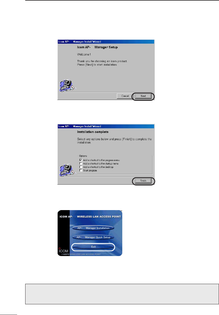
3. The Auto Run will be activated and the main menu
will appear on the screen.
* If Auto Run is not activated, click <Start> and select
“Run”. Enter “D:\AP-12\AutoRun.exe” in the command
line box (when the CD is in drive D) and click
<OK>.
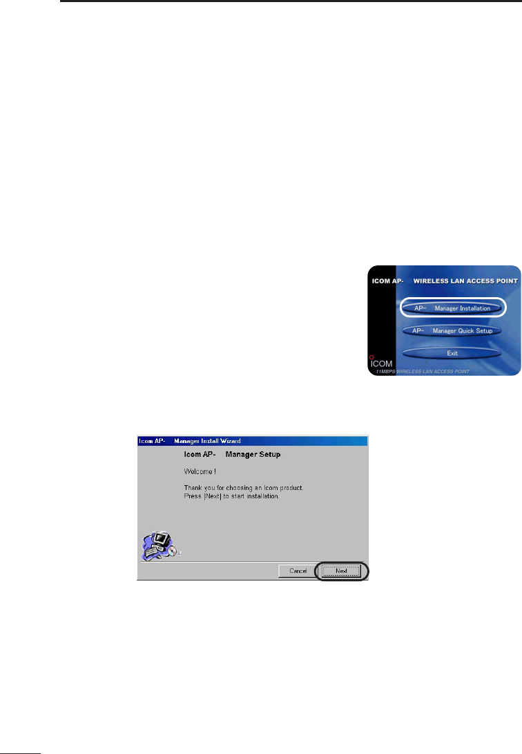
4. Click “Utility Install”.
Click <Next>.
5. Click <Next>.
12
12
COMPUTER SETUP
12
12
12
ap_12(FCC).qxp 02.4.17 2:53 PM ページ18
19
6
COMPUTER SETUP
6
[Installing the utility software] (continued)
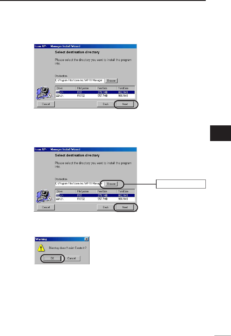
6. Click <Next>.
7. Specify the folder in which you want to install the utility and click <Next>.
* If you want to change the default folder that will appear in the text box as shown
below, click <Browse> and select the desired folder.
8. When the message “Create New Folder” appears on the screen, click <OK>.
12
12
Click <Browse>
ap_12(FCC).qxp 02.4.17 2:53 PM ページ19
20
6
[Installing the utility software] (continued)
9. Click <Install>.
10. Click <Finish>. The installation is now complete.
11. Click <Finish> to close the menu.
COMPUTER SETUP
12
12
12
12
12
12
[Note]
To uninstall the AP-12 Manager, see chapter 8 Operation Tips.
ap_12(FCC).qxp 02.4.17 2:53 PM ページ20
7
21
Starting the AP-12 Manager
This section describes how to start and quit the AP-12 Manager installed in the
computer.
[How to start]
1. Connect the Ethernet port of the product with the Ethernet adaptor (card) port of the
computer using the cross connection Ethernet cable (1 m).
* Be sure to use the provided cross connection Ethernet cable (1 m).
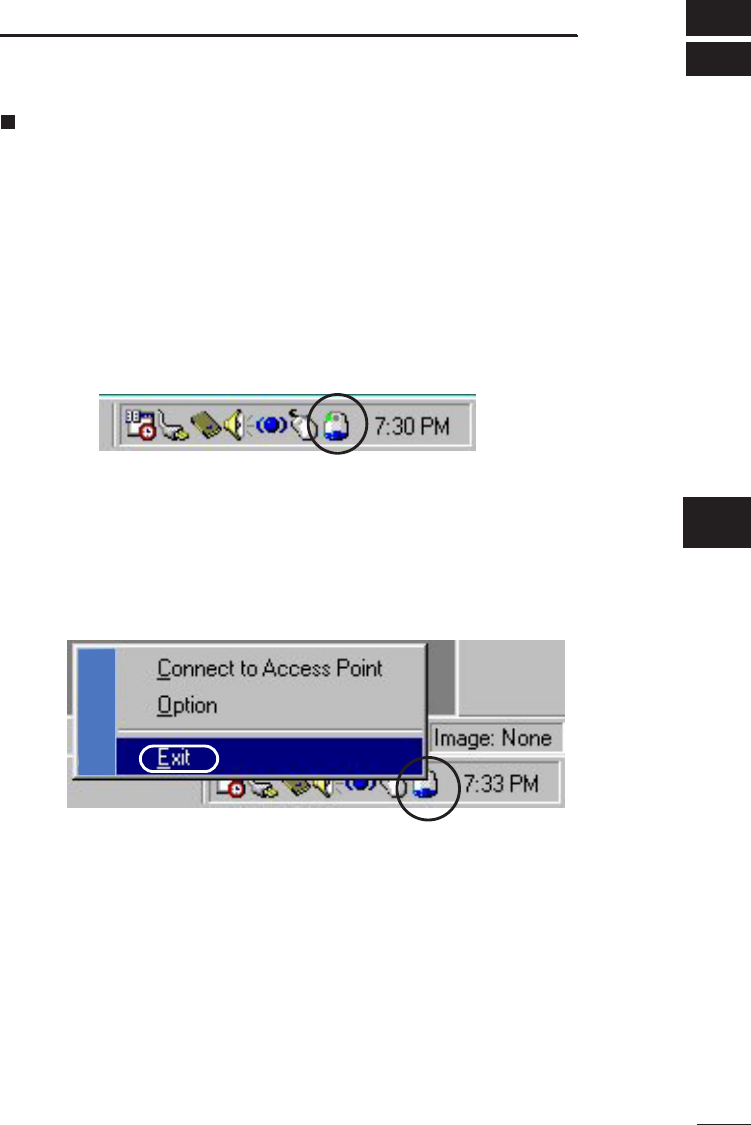
2. Click <Start> and select “AP-12 Manager” from the Program menu. An icon
indicating that the AP-12 Manager is running is displayed on the task bar.
[How to quit]
1. To quit the AP-12 Manager, right-click the AP-12 Manager icon on the task bar and
then select Exit from the pop-up menu that appears.
AP-12 MANAGER
AP-12
7
ap_12(FCC).qxp 02.4.17 2:53 PM ページ21
22
7
Connecting an access point
Using the AP-12 Manager allows you to perform setting required for using the product
and advanced WEP-based security setting.
[How to connect]
Connect the Ethernet port of the product with the Ethernet adaptor (card) port of the
computer using the cross connection Ethernet cable (1 m).
* Product setting with the AP-12 Manager cannot be done unless the ports are
connected.
* Do not use the straight connection Ethernet cable (3m) to connect the ports.
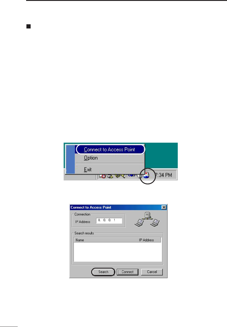
1. Right-click the AP-12 Manger icon on the task bar. Select “Connect to Access Point”
from the pop-up menu that appears.
2. Click the “Connect to Access Point” tab.
3. Click <Search> on the “Connect to Access Point” tab.
AP-12 MANAGER
AP-12
ap_12(FCC).qxp 02.4.17 2:53 PM ページ22
23
7
[How to connect] (continued)
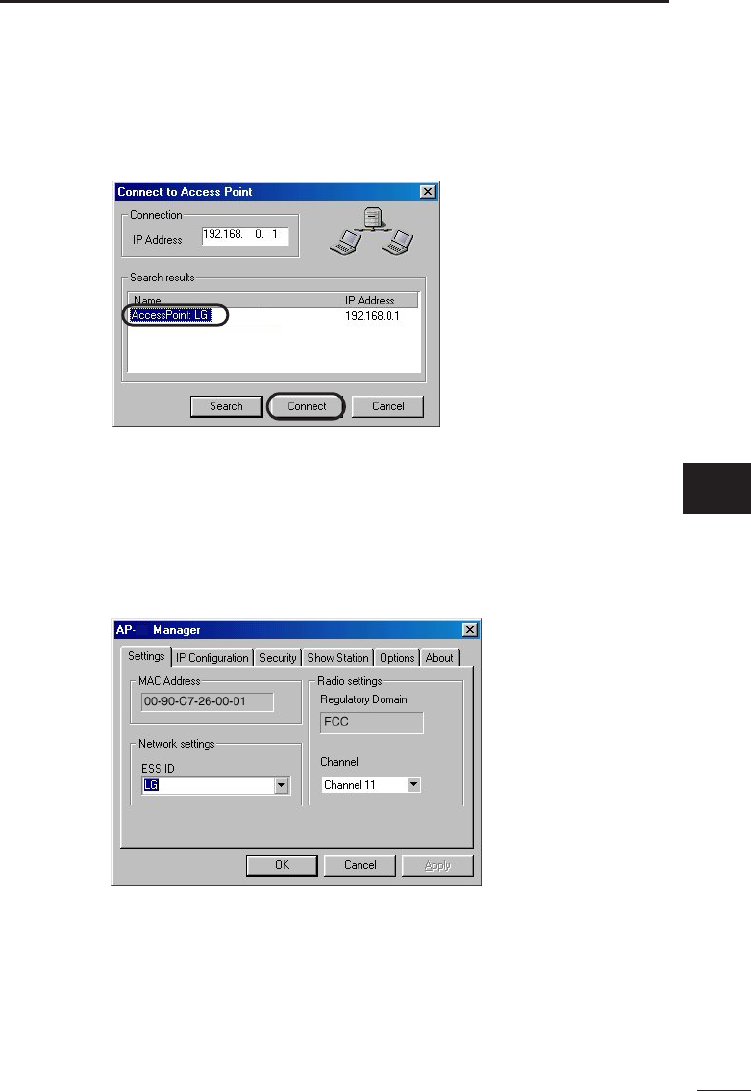
4. All the available access points and their current addresses will be displayed in the
Search Results box,
5. Select the access point you want to access and then click <Connect>.
6. The AP-12 Manager setting menu for the selected access point will appear on the
screen.
This menu includes the “Setting”, “IP Configuration”, “Security”, “Show Station”,
“Option” and “About” tabs.
[Error]
If the error message “Connection to access point has failed” appear on the screen, the
Quick Setup Wizard may have failed in setting the IP address or subnet mask. In such a
case, consult chapter 8 Operation Tips to set the IP address and subnet mask of the
computer manually.
AP-12 MANAGER
12
(AP-12 Manager setting menu)
7
ap_12(FCC).qxp 02.4.17 2:53 PM ページ23
24
7AP-12 MANAGER
Setting
This tab allows setting about wireless communications between the access point and the
wireless LAN card (unit).
MAC address
This field shows the MAC address. The setting in this field cannot be changed.
* The MAC address is a unique address that is assigned to each device in the network.
Network setting
The ESS ID is specified in this field. (Default: LG)
* This setting item serves as an arbitrary name for identifying a group within the wireless
network.
* It is used when multiple wireless workgroups are configured within the wireless
transmission area and there is network information that should not be viewed by other
wireless workgroups. The ESS ID must be the same as the other computers of your
workgroup. Specifying a different ESS ID disables your computer to communicate with
other computers within the group.
* The ESS ID is case sensitive and must be up to 32 alphanumeric characters long.
12
ap_12(FCC).qxp 02.4.17 2:54 PM ページ24
25
7
AP-12 MANAGER
[Procedure] (continued)
Domain name
This field shows the domain name of the product. The domain name cannot be changed.
Channel
The wireless communication channel is specified in this field. (Default: 11)
When multiple access points are used, refer to the following note to set the channels.
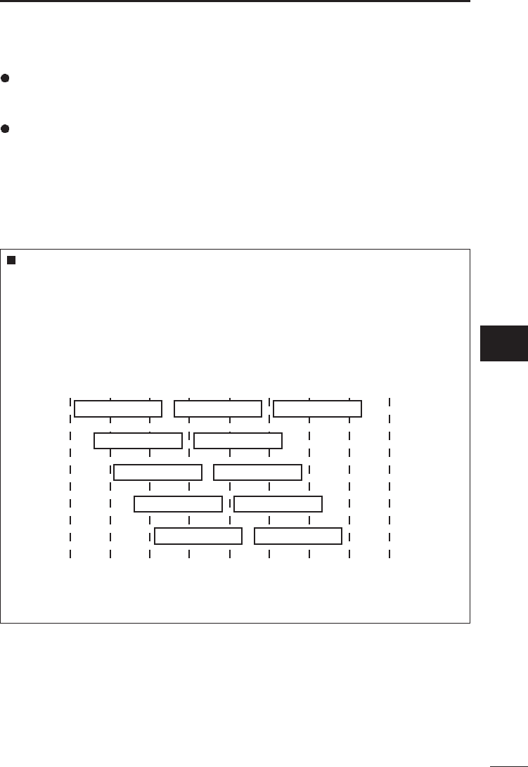
Communication channels
If two or mote access points are placed within the wireless transmission area, it is
recommended to set the communication channels of network groups at least four
channels apart to avoid interference.
Otherwise, interference may occur due to partial overlap in bandwidth as shown
below. Channel settings of 1-6-11, for example, eliminates the possibility of inter-
ference.
2400 2410 2420 2430 2440 2450
Frequency (MHz)
2460 2470 2480
1 channel
2 channel
3 channel
4 channel
5 channel
6 channel
7 channel
8 channel
9 channel
11 channel
10 channel
7
ap_12(FCC).qxp 02.4.17 2:54 PM ページ25

26
7AP-12 MANAGER
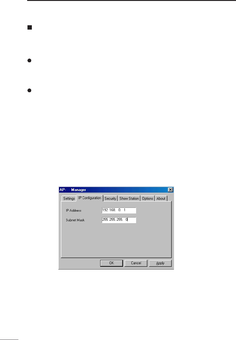
IP Configuration
Setting the IP address and subnet mask
This tab is used to set the IP address and subnet mask so as to allow the product
to be connected to a working network.
IP address: Specify the IP address of the product in this field. (Default: 192.168.0.1)
Subnet mask: Specify the subnet mask in this field. (Default: 255.255.255.0)
[Note]
* The AP-12 cannot be used as a DHCP server. This means the IP address and the
subnet mask of the product must be set manually. The IP address of terminals may be
assigned automatically depending on the network environment. (See the setting
examples shown below).
* The IP address for each computer within a network group must be unique.
* The subnet masks of all the computers within a network group must be the same.
(IP Address setting examples)
The following shows addressing examples where the network comprises three
computers.
AP-12: 192.168.0.40*1(subnet mask: 255.255.255.0)
Wireless terminal A: 192.168.0.41*2(subnet mask: 255.255.255.0)
Wireless terminal B: 192.168.0.42*2(subnet mask: 255.255.255.0)
Wireless terminal C: 192.168.0.43*2(subnet mask: 255.255.255.0)
*1: In case a DHCP server automatically assigns IP addresses to other access points, it
is recommended to specify the IP address of the product as large as practicable in
order to avoid address collision.
*2: If the network contains a DHCP server (such as dialup router) that is capable of
automatically assigning IP addresses, the server capability may be utilized to assign
IP addresses to wireless terminals. In this case, “Obtain an IP address automatically”
is selected during computer setup for networking.
** For details on network settings, see the instruction manuals for the DHCP server
and wireless terminals.
12
ap_12(FCC).qxp 02.4.17 2:54 PM ページ26
27
7
AP-12 MANAGER
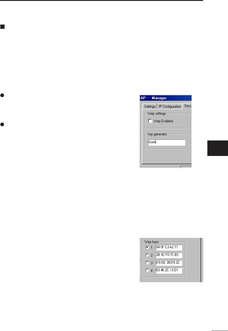
Security
This tab is used to set the degree of WEP (Wired Equivalent Privacy) based encryption
used to protect the data transmitted over the network.
Communications is not permitted unless this field setting is the same for all of the
computers with which you wan to communicate.
[Note]
* WEP setting should be made for the AP-12 and then for each wireless terminal.
WEP enable
If “WEP Enabled” is not selected, no WEP key is used
and therefore no data is encrypted during transmission.
Key generator
Enter a character string for generating the key used for
encryption and decryption. When a character sting is
entered in this field, 4 keys are created automatically
and displayed in the text boxes.
* The same character sting entered in the Key
Generator field will result in the same WEP keys
created in the text bopxes.
* Selecting a key number in the WEP Key area allows proper reception of encrypted
data.
The key is case sensitive and must be up to 30 alphanumeric characters long. Enter the
same key for all of the computers with which you are communicating.
* If different character strings are used, the encrypted data cannot be decrypted.
* Instead of specifying a key for encryption/decryption, you may enter hexadecimal
numerals directly in the WEP key text boxes. (See “WEP key” on the next page).
12
7
ap_12(FCC).qxp 02.4.17 2:54 PM ページ27
28
7AP-12 MANAGER
[Security] (continued)
WEP key
• The [WEP key] text boxes contains lower 40 bits (10 hexadecimal numerals) generated
from the character string entered in the [Key Generator]
box.
• Select check box 1, 2, 3 or 4 that you want to use for
encryption.
• The hexadecimal alphanumerics in the selected text box
are used for encryption. The destination computer cannot
decrypt transmitted data unless it is using the same
hexadecimal alphanumerics for decryption.
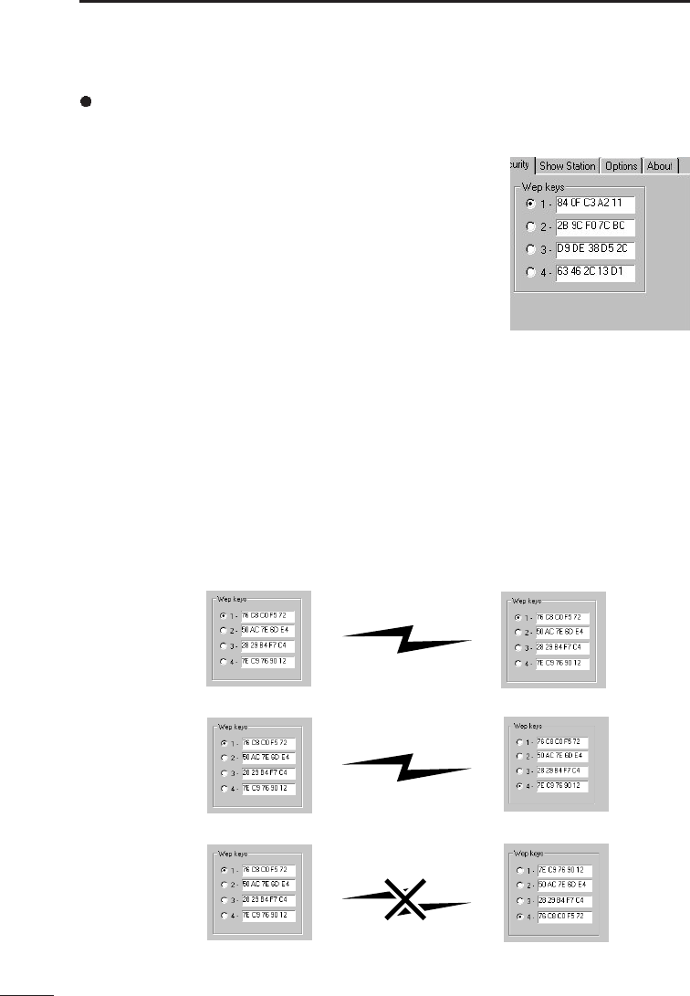
[Customizing the WEP keys]
• Instead of entering a key in the Key Generator box, you may enter up to hexadecimal
alphanumerics directly in the WEP key text boxes.
• When this is done, any character sting in the Key Generator box is ignored.
• Enter the same alphanumerics in each text boxes as other terminals in the network
group. (See examples 1 and 2).
• Otherwise, data communications will fail. (See example 3).
• When the Mask option is selected, the contents in the WEP key text boxes are
displayed as “***”.
Bidirectional
transmission enabled
Bidirectional
transmission enabled
Transmission
disabled
Example 1
Example 3
Example 2
ap_12(FCC).qxp 02.4.17 2:54 PM ページ28
29
7
AP-12 MANAGER
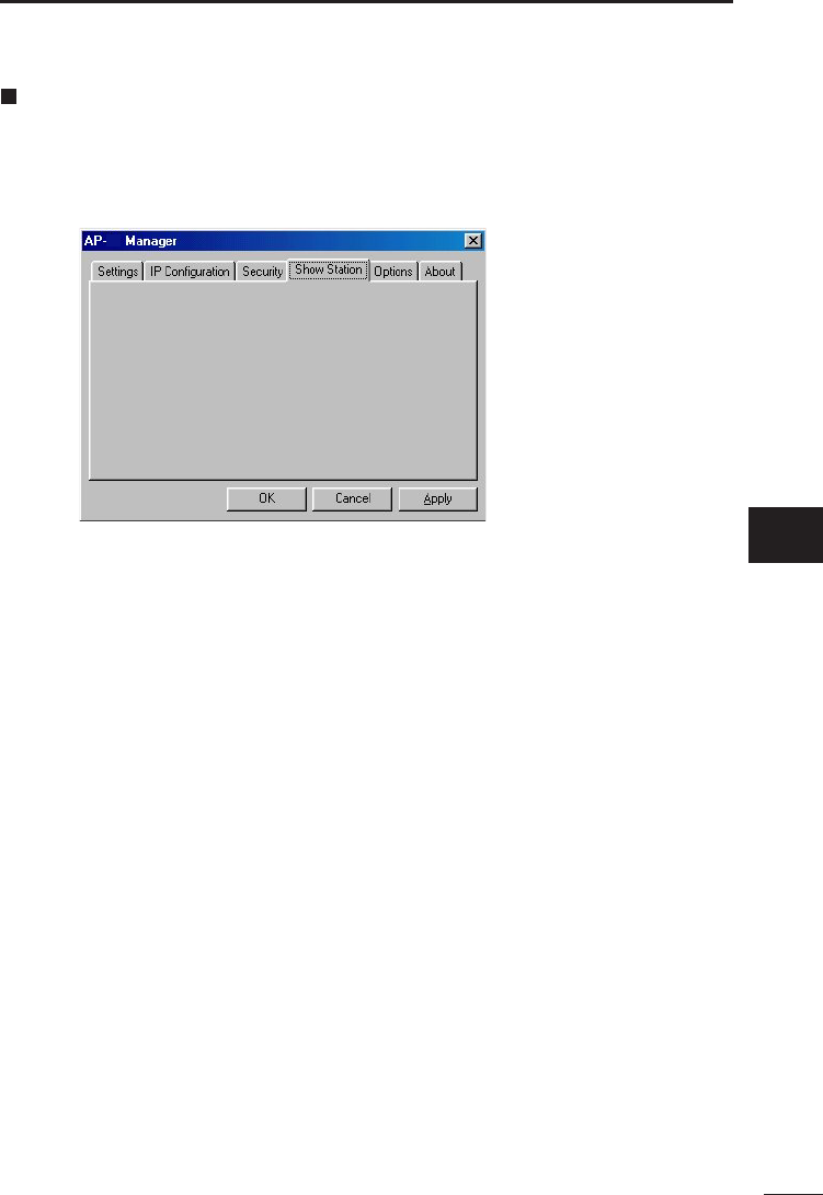
12
Show Station
The current version does not support this feature.
7
ap_12(FCC).qxp 02.4.17 2:54 PM ページ29

30
7AP-12 MANAGER
12
Option
[General]
Display banner
The banner of the AP-12 Manager can be OFF when the
utility starts. (Default: ON)
Icon animation
The animated icon on the task bar shows the operation status of the AP-12.
This icon animation can be OFF. The icon itself remains on the task bar.
(Default: ON)
[Security]
Set a password
Clicking this check box allows you to set a password
required for starting the AP-12 Manager. Setting a pass-
word will provides protection against theft or unauthorized
changes of access point data or settings. Passwords
should be changed periodically.
• Passwords must be up to 32 characters long, and is case sensitive.
• To change passwords, deselect the check box and the click <Apply>.
Mask setting data
The WEP key and key generator data can masked.
Masked data is displayed as “***··”.
These functions are activated by clicking <Apply>.
12
ap_12(FCC).qxp 02.4.17 2:54 PM ページ30
31
7
AP-12 MANAGER
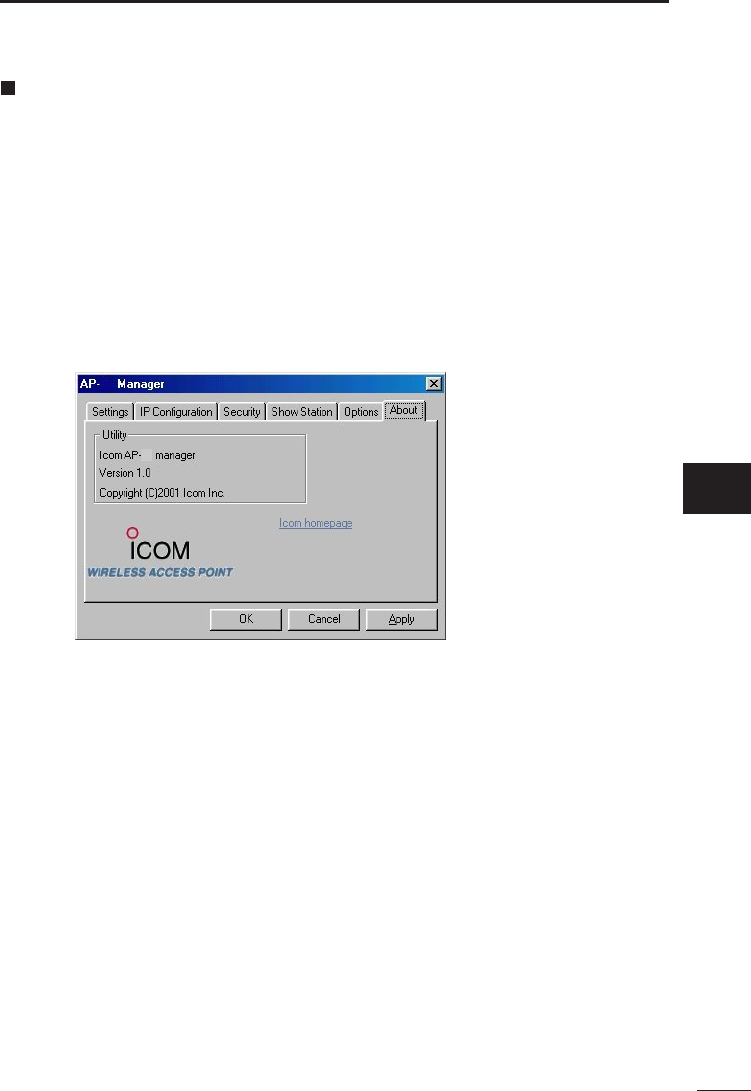
12
12
About AP-12 Manager
This tab shows the version information of the utility software, AP-12 Manager.
Go to Icom home page: If the network containing the AP-12 is connected to the
Internet, clicking here allows you to go to the ICOM home
page.
7
ap_12(FCC).qxp 02.4.17 2:54 PM ページ31
8
32
OPERATION TIPS
Connection to the AP-12 failed
If connection to the desired access point failed even though the AP-12 Manager is used,
the possible causes include the following:
(1) The Ethernet adaptor does not work normally, or
(2) The quick setup wizard has failed in setting the IP address.
[Note]
The following description assumes the 10BASE-T Ethernet card (adaptor) has been
installed in the computer. It the Ethernet card (adaptor) has not yet installed in the
computer, install the card and its driver according to the instruction manual for the card.
* The following procedure applies to a Windows 98 machine.
Checking the Ethernet adaptor
Check if the Ethernet card (adaptor) in the computer works normally as follows:
[Procedure]
1. Click <Start> and select “Control Panel” from the “Settings” menu.
2. Double-click the “System” icon on the “Control Pane” screen.
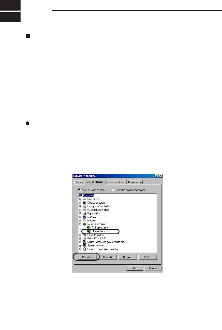
3. Select the “Device Managers” tab and click “+” for the “Network Adapters” icon.
4. Select the “Ethernet Adapter” tab and click <Properties>.
If the driver has been installed properly, the window shown on the next page will
appear on the screen.
* The adaptor name indicated on the screen will vary depending on the adaptor used.
ap_12(FCC).qxp 02.4.17 2:55 PM ページ32
33
8
OPERATION TIPS
[Procedure] (continued)
* If the “Ethernet adaptor” icon are marked with “!” or “×”, or “Ethernet adaptor” are
located under “Other Devices”, the installation of the driver unit driver may have
failed.In such a case, uninstall the driver and then install again.
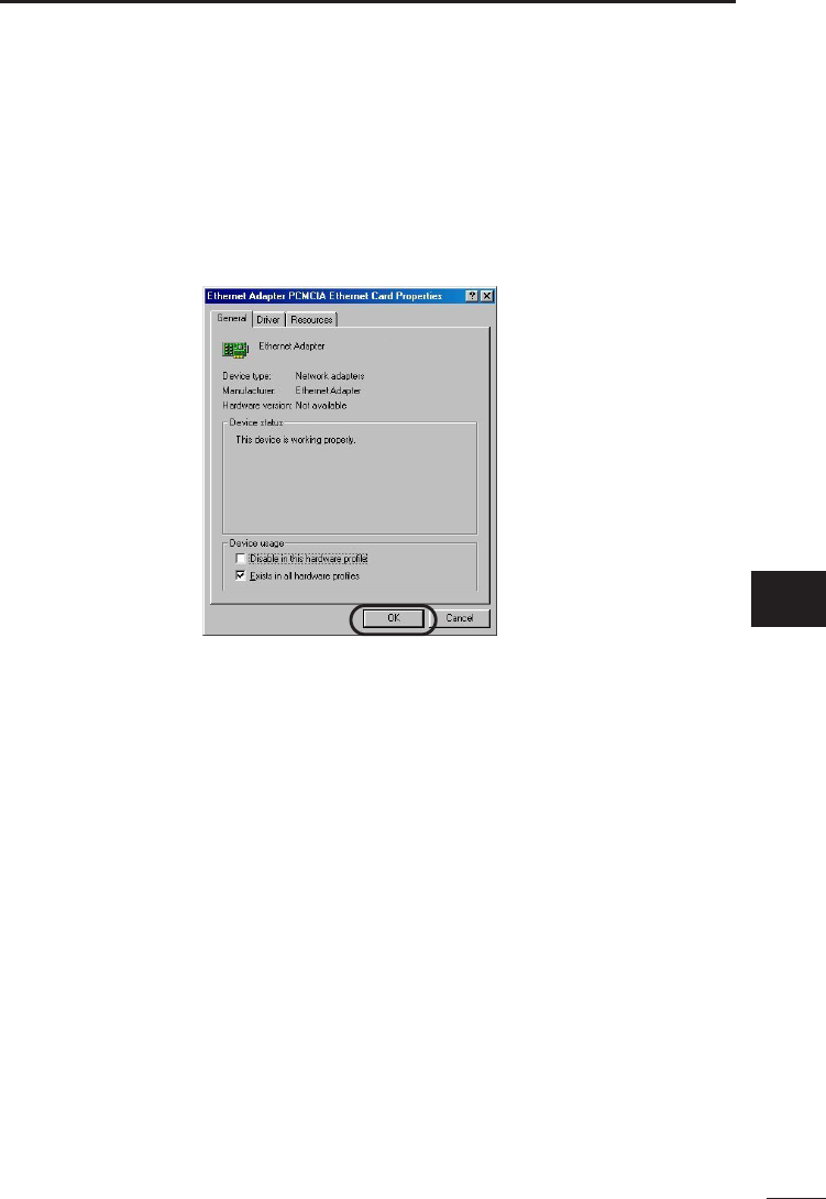
5. Make sure “This device is working properly” appears in the “Device status” field on
the “General” tab of the Properties window.
Click <OK>. The display will return to the window shown in Step 3.
6. Click <OK> on the window shown in step 3.
7. If the Ethernet card (adaptor) works normally, proceed to “Manual setting of IP
address” on the next page.
8
ap_12(FCC).qxp 02.4.17 2:55 PM ページ33
34
8OPERATION TIPS
Manual setting of the IP address
This section describes how to set the IP address of the computer without using the setup
wizard.
[Note]
Before setting or changing the IP address manually, note the present address value so
as to restore the address to the original value when necessary.
[Procedure]
1. Click <Start> and select “Control Panel” from the “Settings” menu. Double-click the
“Network” icon.
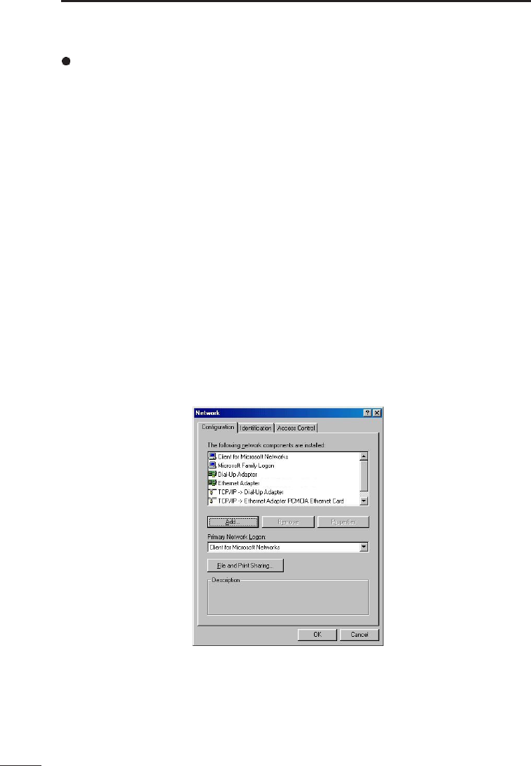
2. Make sure “TCP/IP” and “Client for Microsoft Networks” are displayed on the
“Network Configuration” tab.
If these network components are not displayed on the “Network Configuration” tab,
the installation of these components may have failed.
* Make sure “Client for Microsoft Networks” is displayed in the “Primary Network
Logon” field.
* Make sure the “TCP/IP –> name of LAN card (adaptor) currently used” is displayed
in the “The following network components are installed” field on the “Network
Configuration” tab.
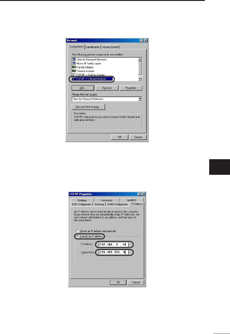
3. Select “TCP/IP” and click <Properties>.
* If multiple network adaptors have been installed, select “TCP/IP –> name of LAN
card (adaptor) currently used”.
ap_12(FCC).qxp 02.4.17 2:55 PM ページ34
35
8
OPERATION TIPS
[Procedure] (continued)
4. Click the “IP Address” tab.
5. Select “Specify an IP address” and enter “192.168.0.10” in the “IP Address” field and
“255.255.255.0” in the “Subnet Mask” field. Then click <OK>.
* The IP address of the product is factory set to 192.168.0.1.
6. The display will return to the window shown in step 3. Click <OK>.
7. When the message “Restart computer now?” is displayed, click <OK>.
After the computer restarts, use the AP-12 Manager to set the product.
8
ap_12(FCC).qxp 02.4.17 2:55 PM ページ35
36
8OPERATION TIPS
Checking the connection with the AP-12
If the IP address of each station (terminal) is set correctly, then you can check if the IP
packets are arriving correctly at their destination by pinging the station of the other
computer.
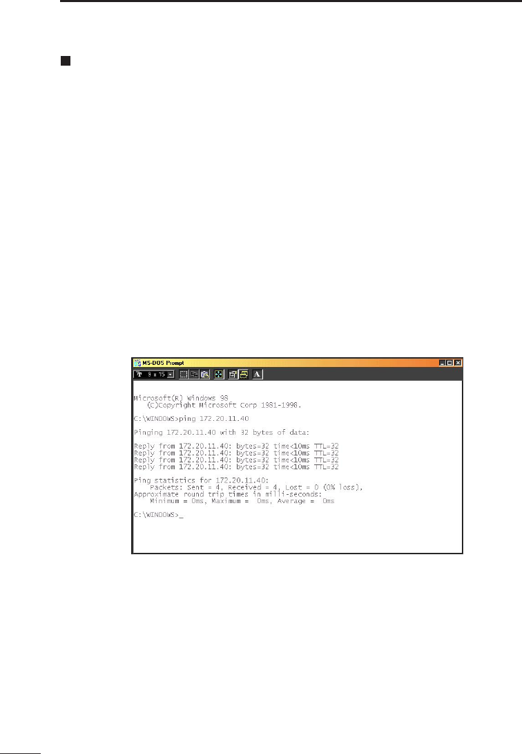
To troubleshoot by pinging, open the MS-DOS window and enter the following
command:
“ping xxx.xxx.xxx.xxx”
where “ xxx.xxx.xxx.xxx” is the IP address of the AP-12.
By executing the ping command, four pings (echo requests) are transmitted and a reply
message should be received for each ping.
If a reply is not received, check the protocol settings of the station, as well as the settings
of the respective wireless LAN cards (Network Mode, ESS ID, etc.).
The message “destination unreachable” will be displayed if the IP address and subnet
mask of the source and destination stations are not set correctly.
""Example of ping command execution (normal case)
Windows 98
ap_12(FCC).qxp 02.4.17 2:55 PM ページ36
37
8
OPERATION TIPS
Uninstalling the AP-12 Manager
This section describes how to uninstall the utility, AP-12 Manager, from a Windows 98
machine.
When your computer uses an operating system other than Windows 98, follow the on-
screen messages or instructions to uninstall the utility.
[Procedure]
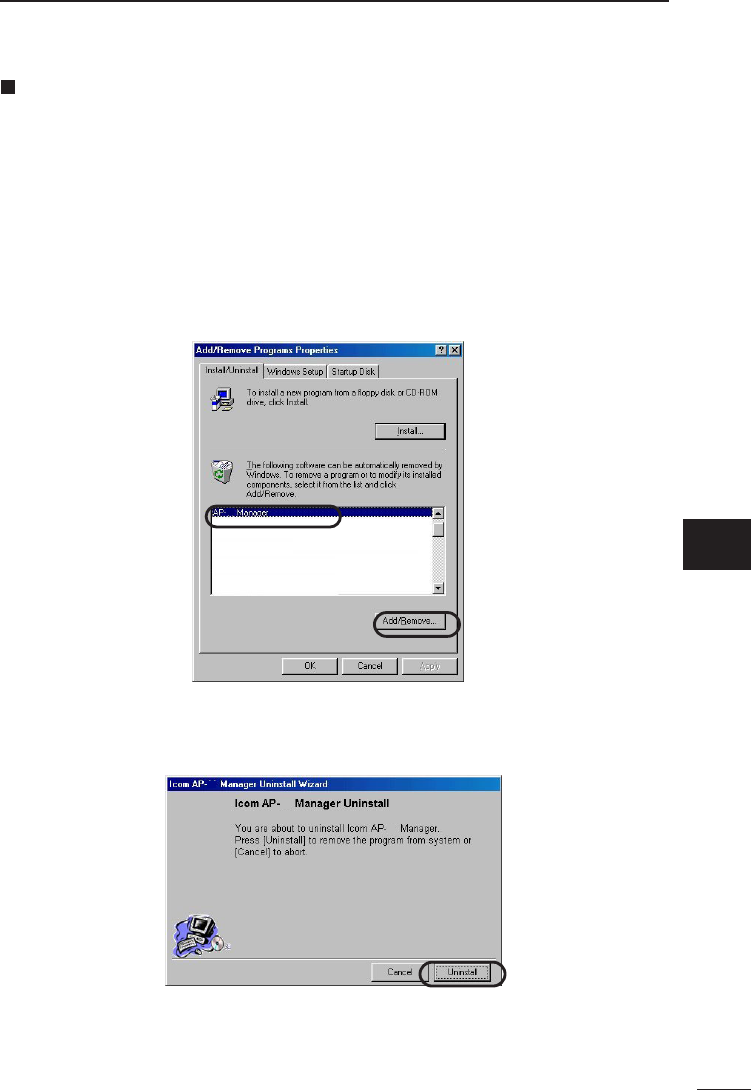
1. Click <Start> and select “Control Panel” from the “Settings” menu. Double-click
“Add/Remove Programs”.
2. Select “AP-12 Manager” and click <Add/Remove>.
3. The AP-12 Manager Uninstall Wizard will start. Click <Uninstall>.
12
12
12
12
8
ap_12(FCC).qxp 02.4.17 2:55 PM ページ37
9
38
SETTING EXAMPLES
Network arrangement
This chapter shows IP address setting examples for the following network arrangement.
This network consists of the product (ICOM access point AP-12), wireless ISDN Router,
wireless LAN card SL-11 and wired and wireless terminals (PCs).
HUB
AP-12
Wireless Transmission Area
PC-2
PC-3(SL-11) PC-1
Internet
Router
[Router settings]
IP address: 192.168.0.1
Subnet mask: 255.255.255.0
DHCP server function: Enable
Initial allocation IP address: 192.168.0.10
Number of allocations: 30
[PC1 (Desktop PC)]
* An Ethernet card is required.
The IP address of this terminal is
assigned by the DHCP server function
of the Router automatically. Select
“TCP/IP”from the installed network com-
ponents on the “Network Configuration”
tab and click <Properties>; and then
select “Obtain an IP address automati-
cally”.
* For setting items not shown here, see
the instruction manuals for respective
devices.
[AP-12 settings (manual)]
Channel: 11
IP address: 192.168.0.40
Subnet mask: 255.255.255.0
* The value subsequent to the last dot
should be set to “40” or more. Otherwise,
the IP address may collide with an IP
address that is automatically assigned by
the Router.
[PC3 (SL-11)*1]
IP address: 192.168.0.42*2
Subnet mask: 255.255.255.0*2
*1 Operation mode: Infrastructure
*2 If the network contains a DHCP server,
the “Obtain an IP address automatically”
option can be selected.
*ESS ID and WEP-related settings must
be the same between the AP-12 and
each wireless terminal (PC2, PC3).
ap_12(FCC).qxp 02.4.17 2:55 PM ページ38

10
REFERENCE
39
10-1 Default Setting Values
The original factory setting values are listed below for each AP-12 setting window.
[Wireless setting]
• ESS ID: LG (alphanumeric characters, upper case)
• Channel: 11
[IP setting]
• IP address: 192.168.0.1
• Subnet mask: 255.255.255.0
[Security]
• WEP security: Disable
• Key generator: Non
[Option]
• Display banner: ON
• Icon animation: ON
• Password protection: OFF
• Setting data mask: OFF
10-2 Function List
• Wireless access point function
• Wireless roaming function
• Wireless security
(ESS ID, WEP)
10-3 Ethernet port
Type RJ-45 8-pin modular jack: 1
1. Send (+)
2. Send (–)
3. Receive (+)
4. Not used
5. Not used
6. Receive (–)
7. Not used
8. Not used
12345678
9
10
ap_12(FCC).qxp 02.4.17 2:55 PM ページ39

11
40
AFTER SERVICE
When the product fails
Warranty
At the time of purchase, the retailer will provide a warranty sheet complete with the
details of the purchase (date of purchase, name of store). Make sure the information
is correct and keep the warranty in a safe place for future use.
Requesting servicing
Refer to the instruction manual and check the settings of both the computer and the
AP-12. If you cannot solve the problem, request servicing according to the following
terms:
Contact the store where you purchased the product.
The retailer will service the product in accordance with the warranty. Have your
warranty ready at the time of request.
Contact the store where you purchased the product.
If the product is serviceable, the retailer will repair the product for a fee.
Questions Regarding Service
If you have any questions regarding service, contact the local dealer where you
purchased the product or contact the service staff at one of our sales offices.
After the warranty period
During the warranty period
ap_12(FCC).qxp 02.4.17 2:55 PM ページ40

12
41
SPECIFICATIONS
11
12
• Applicable international standards :
• Communication method :
• Radio communication type :
• Modulation method :
• Frequency band :
• Available channels :
• Data transmission rates :
• Transmission range :
• Security :
• Built-in antenna :
• Transmission power :
• Reception sensitivity :
• Demodulation method :
• Operating temperature range :
• Input power :
• Power consumption :
• Outline dimensions :
• Mass :
• Supported machines :
• Supported OS :
IEEE 802.11/IEEE 802.11b
Simplex
Direct Sequence Spread Spectrum
(DSSS)
DPSK/DQPSK (Burger/CKK code)
2.4 GHz band (2400 – 2472 MHz)
1 – 11
Max. 11 Mbps
Approx. 30m (indoor) at 11 Mbps
WEP (Wired Equivalent Privacy)
ESSID (Extended Service Set IDentifier)
Diversity slot antenna
Less than 1 W
–76 dBm max. (frame error rate: 8%)
Digital demodulation (matched filter type)
0 – +55°C
7.5 V DC ±5% (using supplied AC adaptor)
Transmit 450 mA (typical)
Receive 400 mA (typical)
100 (W) ×30.5 (H) ×70 (D) mm
(excluding projections)
Approx. 90 g (excluding accessories)
PC/AT compatible machine,
Windows 98, Windows 98 Second Edition,
Windows Millennium Edition,
Windows 2000
Windows XP
* The specifications may be subject to change without notice.
* The transmission range may vary depending on the transmission speed and the
environmental conditions.
ap_12(FCC).qxp 02.4.17 2:55 PM ページ41

13
42
TERMINOLOGY
DHCP server
DHCP (Dynamic Host Configuration Protocol) is a
protocol that allows a client in a TCP/IP network
to automatically obtain required information from
a server.
The DHCP server manages such network
information as the IP Address, Default Gateway,
and Domain Name.
ICOM DR-1WL or other devices with DHCP
server capability allocate an IP address, default
gateway, DNS address, etc., to the DHCP clients
(computers) when the DHCP clients start up.
ESS ID (Extended Service Set-IDentifier)
An ESS ID is a name used for identification when
multiple network groups are formed within the
transmission area of a wireless network. The ESS
IDs of the wireless terminals in a wireless network
group communicating with the AP-12 are set to
the same value as the ESS ID of the AP-12.
Ethernet
Ethernet is a set of standards and protocols for
LAN communications developed by Xerox, Digital
Equipment Corporation, and Intel. Types of Ether-
net include 10BASE-T, 10BASE-5, and 10BASE-
2, each requiring a different cable specification.
IP (Internet Protocol) address
The IP address is a 32-bit address used to
distinguish the devices in a network constructed
using TCP/IP protocol. Each network device has
a unique IP address.
The IP address is usually expressed as a base-10
numeral string made up of four 8-bit sections.
(Example: 192.168.0.1)
A private IP address is an IP address set
independently by the network administrator.
It is not necessary to petition an address manage-
ment institution or a provider, but a private IP
address must be allocated according to the
following rule:
When connecting with an external network, the
private address must be converted into a global
IP address.
The following IP addresses can be used freely as
private IP addresses:
Class A:
10.0.0.0 to 10.255.255.255
Class B:
172.16.0.0 to 172.31.255.255
Class C:
192.168.0.0 to 192.168.255.255
LAN (Local Area Network)
A network that is relatively small in scale. A
typical LAN occupies a single office or a single
floor of a building.
MAC address (Media Access Control Address)
A MAC address is a physical address (number)
uniquely set into each wired or wireless LAN card.
LAN card manufacturers manage MAC addresses
so that no two LAN cards in the world have the
same MAC address.Ethernet uses the MAC
address to send and receive frames.
TCP/IP
TCP/IP is the basic protocol of the Internet and is
currently the most popular protocol in the world. It
is supported by Windows 95/98, Windows NT,
and the other major operating systems.
SMTP and FTP use this protocol.
A TCP/IP control panel is a standard item in
Macintosh computers provided with Open Trans-
port.
URL (Uniform Resource Locator)
URLs are used to access home pages and other
sites on the Internet.
Our URL is http://www.icom.co.jp.
Web browser
A web browser is a software application used for
searching web servers and viewing web pages.
Common applications include Internet Explorer
and Netscape Navigator.
10BASE-T
10BASE-T is a connection scheme for Ethernet
configurations using twisted pair cable.
The “10” in 10BASE-T represents an Ethernet
transmission speed of 10 Mbps and the “T”
represents twisted pair cable.
ap_12(FCC).qxp 02.4.17 2:55 PM ページ42

13
43
TERMINOLOGY
13
Access point
An access point is any device used to connect a
wired LAN to a wireless LAN.
Client
A client is any terminal or application in a network
that requests information or a service from a
server and receives the corresponding response.
Global IP address
A global address is a globally unique address that
held by only one device on the entire internet.
Subnet mask
A subnet mask is used to allow on IP address
represent both the network address and the host
address.
Assuming the IP address of a certain host is
192.168.0.1 and the subnet mask is 255.255.255.0,
if the IP address and subnet mask are multiplied
as binary numbers the network address will be
192.168.0.0 and the remaining 1 will be the host
address.
Traffic
Traffic refers to the flow of packets over a network
or the load (amount of data) born by the network
circuits.
When the traffic is high, data transfers may be
delayed and data may be lost.
Network
An arrangement wherein servers, work stations,
computers, and other devices are connected via
cable or a telephone circuit for the purpose of
exchanging data.
Packet
The unit by which data is sent and received in a
network.
A packet comprises a header portion containing
information required for sending and receiving
and a data portion containing the data being sent.
Password
A character string that a user must enter in order
to access a network. The password provides
network security because, once established, the
password must be entered correctly by the user
or access will be denied.
Hub
A hub is required when the AP-12 and other
devices are used construct a network. The hub is
connected to the AP-3 using 10BASE-T cable.
Flash memory
The flash memory is a memory device in the AP-
12 to which data can be written.
Information stored in the flash memory is not
erased when the power to the AP-12 is turned off.
Protocol
A protocol is a defined set of steps that is
followed when data is sent and received.
ap_12(FCC).qxp 02.4.17 2:55 PM ページ43

1-1-32, Kamiminami, hirano-ku, Osaka 547-0003, Japan
Count on us!
A-6166G-1EU ©2002 Icom Inc.
ap_12(FCC).qxp 02.4.17 2:50 PM ページii