ICOM orporated AP-3 Access Point User Manual ap 3e qxp
ICOM Incorporated Access Point ap 3e qxp
UserManual.wiki
>
ICOM orporated
>
AP 3 User Manual
Manual
Navigation menu
Upload a User Manual
Namespaces
Wiki Guide
HTML
PDF
Info
Views
User Manual
Discussion / Help
Navigation
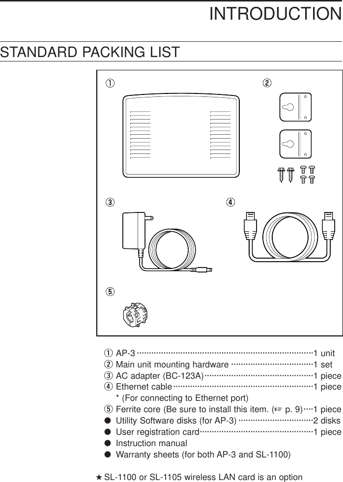
![CONTENTSı-2 ESS ID ·························································39ı-3 Checking the settings···································39ÇStarting the AP-3 and computer···························416-4 Accessing the Setting Screen···································426-5 Testing the Operation················································437. WIRELESS FUNCTIONS ——————————————457-1 Wireless Access Point Function ·······························457-2 Roaming Function·····················································468. SETTING SCREENS————————————————478-1 [Wireless LAN Settings] Screen ·······························47■Wireless LAN settings··········································47■SL-1100 or SL-1105 advanced settings···············47■MAC address security settings ····························508-2 [AP-3 Network Settings] Screen·······························51■Routing mode setting···········································51■AP-3 IP address settings ·····································51■DHCP server settings ··········································52■Static DHCP server settings ································548-3 [Routing Settings] Screen·········································55■RIP setting ···························································55■IP routing information···········································55■Static routing settings···········································578-4 [AP-3 Management Settings] Screen ·······················58■Manager ID settings·············································58■SYSLOG settings·················································599. SAVING AND UPLOADING SETTING DATA —————609-1 [Save Settings] Screen ·············································609-2 Saving Setting Data··················································619-3 Uploading Setting Data·············································62■Precautions regarding editing ······························6210. SETTING DATA INITIALIZATION ——————————63ÅUsing the <INIT> button·······································63ıUsing the setting screen ······································6511. UPDATING THE FIRMWARE ————————————6612. UTILITY SOFTWARE ———————————————6712-1 About the Utility·························································6712-2 Installing the Utility····················································6712-3 Using the Utility·························································68ÅStart up the AP-3 in [Utility Use Data Update Mode] ··························68························································Continued on following page](https://usermanual.wiki/ICOM-orporated/AP-3/User-Guide-130793-Page-7.png)
![ıConnect the setting terminal (computer)··············68ÇStart up the utility·················································68ÎOperate the utility·················································69Î-1 Initializing the setting data····························69Î- 2 Updating the firmware ································7013. SETTING SCREEN CONFIGURATION MAP —————7214. REFERENCE INFORMATION————————————7314-1 Default Setting Values ··············································7314-2 Function List ·····························································7314-3 [ETHERNET] Port·····················································7314-4 Basic Setting Example··············································7414-5 Practical Setting Example·········································7515. MAINTENANCE ——————————————————76■Checking the connection with the AP-3···············7616. AFTER SERVICE —————————————————77■When the unit fails ···············································7717. SPECIFICATION —————————————————7818. GLOSSARY ———————————————————78CONTENTS](https://usermanual.wiki/ICOM-orporated/AP-3/User-Guide-130793-Page-8.png)
![PANEL DESCRIPTION26■Front and rear panels■Front panel■Rear panelwireless LANLANLANPOWERDCWIRELESS LAN CARDETHERNETHUB PCRESETINITMODEThis lamp illuminates when the power to the AP-3 unit ison.This lamp flashes slowly when the unit is in [Initializemode] (☞p. 63) and rapidly when the unit is in [UpdateMode] (☞p.68). q[POWER] lamp·········This lamp illuminates when the wired LAN (Ethernet) con-nection is normal.This lamp flashes when the AP-3 unit is communicatingwith a wired LAN or wireless LAN.This lamp goes out if the [ETHERNET] port on the rearpanel can not recognize the LAN connection. In this case,check the connection of the Ethernet cable and the set-ting of the [HUB/PC] switch. (☞p. 8, 14, 15)w[LAN] lamp ···············This lamp illuminates when the wireless connection to theAP-3 unit is normal.This lamp goes out if a wireless communication abnor-mality occurs. The lamp will also go out if all wireless ter-minals are inactive for more than one or two minutes ormove out of the wireless communication area for morethan one or two minutes. If this lamp does not illuminate, check such items as theIP address of the wireless terminal, the [Network Mode]and [ESS ID] (☞p. 38) of the wireless LAN card installedin the wireless terminal, and the [MAC Address Security]settings (if used). * This lamp cannot be used to determine whether or notthe LAN card is installed into the PCMCIA slot. elamp····](https://usermanual.wiki/ICOM-orporated/AP-3/User-Guide-130793-Page-14.png)
![PANEL DESCRIPTION 27Connect the AC adapter (BC-123A) to this jack. Be surethe ferrite core (☞p. 9) is attached to the AC adaptercord.rDC jack ·····················Connect a grounding wire to this terminal.Use a commercially available grounding wire. tGround terminal ······This button is used to put the AP-3 unit into [Utility UseData Update Mode], which is the mode used for using theUtility to update the firmware or initialize the setting data. * See “12 Utility Software” (☞p. 67) for instructionsregarding how to operate the Utility. y[MODE] button·········This button is used to put the AP-3 unit into [SettingInitialization Mode], which is a mode used for initializingthe setting data to the original factory settings. * See “10 Setting Data Initialization” (☞p. 63) for instruc-tions regarding how to use [Setting Initialization Mode]mode.u[INIT] button·············This button is used to restart the AP-3 unit (i.e. initializeits hardware).* The result is the same as turning off the power and turn-ing it back on.i[RESET] button········This is an RJ-45 type Ethernet port.Connect a computer or a hub to the AP-3 unit using theprovided Ethernet cable (straight cable). * This port can also be used for 100BASE-TX (high-speed wired LAN) communications.* Use a Class 5 cable (such as the provided Ethernetcable) or higher level cable when conducting 100BASE-TX communications. Avoid lower grade cables.If a lower grade of cable is used, the grade of the entirenetwork will be pulled down to the same level.* If the [LAN] lamp does not illuminate when the power ison and the AP-3 unit is connected to the wired LAN,change the setting of the [HUB/PC] switch (☞p. 8).·············································Continued on following pageo[ETHERNET] port·····](https://usermanual.wiki/ICOM-orporated/AP-3/User-Guide-130793-Page-15.png)
![PANEL DESCRIPTION28■Front and rear panels (continued)This switch is used to switch the polarity of the [ETHER-NET] port.The switch has the following two positions based on dif-ferences in Ethernet cable type and the hub port beingused.[PC]: This position sets the [ETHERNET] port to cross-over mode (symbol: ✕). Use this setting when an Ethernet cable (straightcable) is used to connect the AP-3 unit to thestraight port (symbol: =) of a hub or the port (sym-bol: =) on the Ethernet card side of a computer.(☞ p. 14)[HUB]: This position sets the [ETHERNET] port tostraight mode (symbol: =). Use this setting when an Ethernet cable (straightconnection) is used to connect the AP-3 unit to thecross-over port (symbol: ✕) of a hub. (☞p. 15)!0 [HUB/PC] switch······This is a slot for inserting an ICOM wireless LAN card.(☞p. 10)* Turn of the power to the AP-3 unit before inserting orremoving the LAN card.* This slot is compatible with any ICOM wireless LANcard. (as of May 2000).* When the SL-1100 LAN card is used with the AP-3 unit,use the same model of LAN card with the client as well.!1 PCMCIA slot·············](https://usermanual.wiki/ICOM-orporated/AP-3/User-Guide-130793-Page-16.png)
![BEFORE CONNECTING CABLES 393-1 Attaching theFerrite CoreBefore using the AC adapter, attach the provided fer-rite core to the cord in the position shown below.Otherwise the AC adapter may cause signal interfer-ence.3-2 Selecting anInstallationSiteThe installation site for the wireless access pointmust be selected carefully in order to avoid signalinterference and reductions in transmission speedand range.Observe the following guidelines when selecting thelocation.●Select a location with as clear a line of sight as possi-ble (i.e., as high as possible). ●Select a stable, level surface that is free of vibrationsand the danger of the unit falling.●Also observe the following:• Do not place objects on top of the unit or stack unitson top of one another.• Radio signals will pass through walls and glass butnot through metal. Concrete walls may be reinforcedwith steel or other metal material that will block thesignal.• The transmission range is widest in an open space.However, the signal may be reflected from the largemetal walls in such a location as a warehouse. • Floors generally have steel girders and are installedwith metal fire protection material. Consequently,communication between different floors is often notpossible.• Do not install in a location exposed to intense radiowaves (such as near a wireless station) or intenseelectromagnetic radiation (such as near a radio trans-mission tower). Connect the ferrite core close to the DC plug. Wrap the cord once around the ferrite core and close the ferrite cord until it locks with a clicking sound. *Supplied AC adapter may differ depends on version.[NOTE]The transmission rangevaries somewhat dependingon the installation location.Use the line-of-sight dis-tances indicated below asguidelines when using anSL-1100 or SL-1105 wirelessLAN card. Indoors : approx. 50 mOutdoors : approx. 150 mWhen transmission speed is11 MbpsIndoors : approx. 30 mOutdoors : approx. 70 m](https://usermanual.wiki/ICOM-orporated/AP-3/User-Guide-130793-Page-17.png)
![BEFORE CONNECTING CABLES 3113-4 Mounting the AP-3 UnitTo mount the AP-3 unit to a wall or shelf, refer to thefigure below and use the provided metal fittings.2. Mount the AP-3 unit. [Mounting to a shelf]When there is the possibility that people will come intocontact with the cables and power cord, secure the AP-3with the mounting fittings as shown in the figure to pre-vent the unit from falling.1. Attach the mountingfittings to the unit.Special machine screws (4) (included)Mounting fittings (included)Wireless LAN cardAP-3 (bottom)Tapping screws (2) (included)Mounting fitting (included)Mounting fitting (included) ShelfAP-3 (top)](https://usermanual.wiki/ICOM-orporated/AP-3/User-Guide-130793-Page-19.png)
![BEFORE CONNECTING CABLES3123-4 Mounting the AP-3 Unit (continued)2. Mount the AP-3 unit. (continued)[Mounting horizontally to a wall][Mounting to vertically to a wall]WallMounting fittings (2) (included)Tapping screws (2) (included)Wireless LAN cardAP-3 (top)Tapping screws (2) (included)WallMounting fittings (2) (included)Wireless LAN cardAP-3 (top)](https://usermanual.wiki/ICOM-orporated/AP-3/User-Guide-130793-Page-20.png)
![BEFORE CONNECTING CABLES 3133-5 Connection Precautions●Use the [ETHERNET] port to connect the AP-3 unit tothe hub or computer.When connecting the [ETHERNET] port to a computerusing a straight Ethernet cable, set the [HUB/PC]switch to “PC.” (☞pp. 8 and 16)●Computers connected to the [ETHERNET] port or thehub will require an Ethernet card (board).●Be sure to turn the AP-3 power off before inserting orremoving the LAN card.●Do not connect the AP-3 to a working network using theoriginal factory settings.Also, turn off all computers except the one being usedto change the settings when adjusting the settingswhile the AP-3 is connected via a cable or wireless con-nection to computers in a network. Otherwise IP address conflicts or other network prob-lems may occur.●ICOM wireless LAN cards do not support Macintosh.●This unit cannot communicate with any wireless LANcard other than the specified ICOM wireless LAN card.●Hold the connector when connecting and disconnectingthe Ethernet cable.](https://usermanual.wiki/ICOM-orporated/AP-3/User-Guide-130793-Page-21.png)
![CABLE CONNECTIONS4144-1 Connecting to a Computer* The following models of ICOM wireless LAN card can be used: SL1100 or SL-1105. *1. The provided Ethernet cable is a straight-through cable.*2. Turn the power off before changing the position of the [HUB/PC] switch. Set the switch to “HUB” when using a cross-over cable to connect to theEthernet card of a computer. *3. ICOM wireless LAN cards do not support Macintosh.Wireless LAN card Wireless LAN cardDCWIRELESS LAN CARDETHERNETHUBPCRESETINITMODEHUB/PC ComputerSee “3-3 Inserting the Wireless LAN Card” (☞ p. 10) regarding how to insert the LAN card.Insert into the card slot.Ethernet cable (included)*2*3*1<Wireless LAN card settings>When connecting the AP-3 to the Ethernet card of a computer using the provided Ethernet cable (straight cable), set the [HUB/PC] switch to “PC” as shown below.• Set the ESS ID of the wireless LAN card inserted into the AP-3 to the same value as the ESS ID of the wireless LAN card inserted into the computer. (☞ p. 47)• Check the [Network Mode] setting of the card inserted into the computer. (☞ p. 38)Make sure the [ESS ID] setting is the same as that of the card inserted into the AP-3. (☞ p. 39)](https://usermanual.wiki/ICOM-orporated/AP-3/User-Guide-130793-Page-22.png)
![CABLE CONNECTIONS 4154-2 Connecting to a HUB*1. The provided Ethernet cable is a straight-through cable.*2. Turn the power off before changing the position of the [HUB/PC] switch. Set the switch to “PC” when using a cross-over cable to connect to the cross-over port of a hub. *3. Use straight Ethernet cable to connect computers to the cross-over port of thehub. DCWIRELESS LAN CARDETHERNETHUB PCRESETINITMODEHUB/PC ComputerComputerHUBEthernet cable (straight cable)*2*3Ethernet cables (included)*1Cross-over port of hubWhen connecting the AP-3 to the cross-over port of a hub using the provided Ethernet cable (straight cable), set the [HUB/PC] switch to “HUB” as shown below.](https://usermanual.wiki/ICOM-orporated/AP-3/User-Guide-130793-Page-23.png)
![COMPUTER SETTINGS 5175-1 Network SettingsWhen adjusting the settings of the AP-3 unit (☞p. 37),it is better to connect the computer to the AP-3 unitwith a cable. This chapter is written under theassumption of a cable connection between the com-puter and the AP-3 unit.Before connecting the computer to the AP-3 unit,adjust the protocol (TCP/IP) settings of the computer.• Proceed to Chapter 6 (☞p. 37) for instructions regard-ing how to connect a computer that is already beingused in the LAN and use it to adjust the settings of theAP-3. In such a case, delete all the currently allocatedIP addresses and the default gateway.• When using a computer that has never been used in aLAN environment, check the items listed below.ÅCheck Ethernet card Make sure the computer to be used is installed with anEthernet card (Ethernet board) and the provided AP-3 dri-ver is installed on the Ethernet card. See the instruction manual provided with the Ethernetcard regarding how to install the driver (if necessary).ıCheck protocol Make sure TCP/IP is installed in all of the computers. If installation is required, refer to the Help screen of theoperating system or the instruction manual provided withthe Ethernet card.ÇCheck TCP/IPsettingsWindows 95 and 98, Windows NT 4.0, Windows 2000,and Open Transport of the Mac OS all support DHCPclient. * If the computer does not support DHCP client, set thefollowing four items manually. • Local IP address • Subnet mask• Gateway address • DNS server address[About wireless LAN settings]See the instruction manual provided with the ICOM wireless LAN card for instructions regarding how to setthe protocol (TCP/IP) settings of the computer (Windows) into which the wireless LAN card will be insert-ed and used for the wireless connection with the AP-3.](https://usermanual.wiki/ICOM-orporated/AP-3/User-Guide-130793-Page-25.png)
![COMPUTER SETTINGS5185-1 Network Settings (continued)Ç-1 Windows 95 and 98When using Windows 95 or 98, adjust the TCP/IP set-tings according to the following procedure:1. Start up the computer.2. Click <Start> and select [Control Panel] from the[Settings] menu. Then click the [Network] icon. Thescreen shown below is displayed.• Follow the instructions (1 and 2) indicated on thescreen shot below.You will make the follow-ing settings during theprocedure to the right:• IP AddressSetting: “Obtain an IPaddress automatically”• WINS ConfigurationSetting: “Disable WINSResolution”• GatewaySetting: leave blank• DNS ConfigurationSetting: “Disable DNS”[NOTE]When the network settingsare changed, the previoussetting values will be erased. wClick <Properties>.qClick the TCP/IP icon for the Ethernet card (☞ *1)*1. If there are multiple TCP/IP icons q, select the onewith the corresponding adapter name.If only one adapter is installed, simply click “TCP/IP.”*2. If a TCP/IP icon is not included in the list of installedcomponents, refer to the Help screen of the operatingsystem or the instruction manual provided with theEthernet card for instructions regarding how to installthe TCP/IP protocol.](https://usermanual.wiki/ICOM-orporated/AP-3/User-Guide-130793-Page-26.png)
![COMPUTER SETTINGS 5193. Select “Obtain an IP address automatically.”Click4. Click the [WINS Configuration] tab and select “DisableWINS Resolution.”Click](https://usermanual.wiki/ICOM-orporated/AP-3/User-Guide-130793-Page-27.png)
![COMPUTER SETTINGS5205. Click the [Gateway] tab and make sure there are noinstalled gateways.Leave blank6. Click the [DNS Configuration] tab and select “DisableDNS.” Then click <OK>.Click to close TCP/IP properties screen.ClickÇ-1 Windows 95 and 98 (continued)[NOTE]When the IP address of theLAN computer was set man-ually (i.e., not using DHCP),enter the IP address of theAP-3 unit as the address ofthe DNS server.7. Click <OK> on the [Network] screen (☞Step 2, p. 18).8. A message offering to restart the computer is dis-played. Select <No> because you will shut down thecomputer instead.9. Click <Start> and select [Shut Down]. Then select“Shut down” and click <OK>.10. After the computer shuts down, proceed to Chapter 6(☞p. 37).](https://usermanual.wiki/ICOM-orporated/AP-3/User-Guide-130793-Page-28.png)
![COMPUTER SETTINGS 5215-1 Network Settings (continued)Ç-2 Windows NT 4.0(WorkStation)You will set the followingitems during the proce-dure to the right:• IP Address• DNS• WINS Address• Routing[NOTE]When the network settingsare changed, the previoussetting values will be erased. When using Windows NT 4.0, adjust the TCP/IP set-tings according to the following procedure:1. Start up the computer.• The Windows NT 4.0 [Log on] screen is displayed.2. Log on as an Administrator.3. Click <Start> and select [Control Panel] from the[Settings] menu. Then click the [Network] icon. Thescreen shown below is displayed.4. Follow the instructions (1 and 2) indicated on thescreen shot below.qClick the TCP/IP icon.wClick <Properties>.* If a TCP/IP icon is not included in the list of network pro-tocols, refer to the Help screen of the operating systemor the instruction manual provided with the Ethernetcard for instructions regarding how to install the TCP/IPprotocol.](https://usermanual.wiki/ICOM-orporated/AP-3/User-Guide-130793-Page-29.png)
![COMPUTER SETTINGS5225. Follow the instructions indicated on the screen shotbelow.Select the correct Ethernet card.Click6. Click the [DNS] tab and follow the instructions indicat-ed on the screen shot below.Select the correct Ethernet card.ClickÇ-2 Windows NT 4.0 (WorkStation) (continued)[NOTE]When the IP address of theLAN computer was set man-ually (i.e., not using DHCP),enter the IP address of theAP-3 unit as the address ofthe DNS server.](https://usermanual.wiki/ICOM-orporated/AP-3/User-Guide-130793-Page-30.png)
![COMPUTER SETTINGS 5237. Click the [WINS Address] tab and follow the instruc-tions indicated on the screen shot below.Do not enter anything.Do not enter anything.Select the correct Ethernet card.Remove check marks.8. Click the [Routing] tab and follow the instructions indi-cated on the screen shot below.Remove check mark.Click](https://usermanual.wiki/ICOM-orporated/AP-3/User-Guide-130793-Page-31.png)
![COMPUTER SETTINGS5249. Click <OK>.Click10. Click <No>.ClickÇ-2 Windows NT 4.0 (WorkStation) (continued)11. Click <Start> and select [Shut Down]. Then select“Shut down” and click <OK>.12. After the computer shuts down, proceed to Chapter 6(☞p. 37).](https://usermanual.wiki/ICOM-orporated/AP-3/User-Guide-130793-Page-32.png)
![COMPUTER SETTINGS 525Ç-3 Windows 2000 (Professional)When using Windows 2000, adjust the TCP/IP set-tings according to the following procedure:1. Start up the computer.• The Windows 2000[Log on] screen is displayed.2. Log on as an Administrator.3. Click <Start> and select [Dial-Up Networking] from the[Settings] menu. The screen shown below is displayed.qwClick the TCP/IP icon.Click <Properties>.5-1 Network Settings (continued)4. Right-click the [Local Area Connection] icon and select[Properties]. The screen shown below is displayed.• Follow the instructions indicated on the screen shotbelow.](https://usermanual.wiki/ICOM-orporated/AP-3/User-Guide-130793-Page-33.png)
![COMPUTER SETTINGS5265. Follow the instructions indicated on the screen shotbelow.qweClickClick Click6. Follow the instructions indicated on the screen shotbelow.Make sure “DHCP enabled” is displayed. Make sure "1" is displayed.Ç-3 Windows 2000 (Professional) (continued)[NOTE]When the IP address of theLAN computer was set man-ually (i.e., not using DHCP),enter the IP address of theAP-3 unit as the address ofthe DNS server.](https://usermanual.wiki/ICOM-orporated/AP-3/User-Guide-130793-Page-34.png)
![COMPUTER SETTINGS 5277. Click the [DNS] tab and follow the instructions indicat-ed on the screen shot below.Add check mark.Add check mark.Click8. Click the [WINS] tab and follow the instructions indicat-ed on the screen shot below.Add check mark.Click](https://usermanual.wiki/ICOM-orporated/AP-3/User-Guide-130793-Page-35.png)
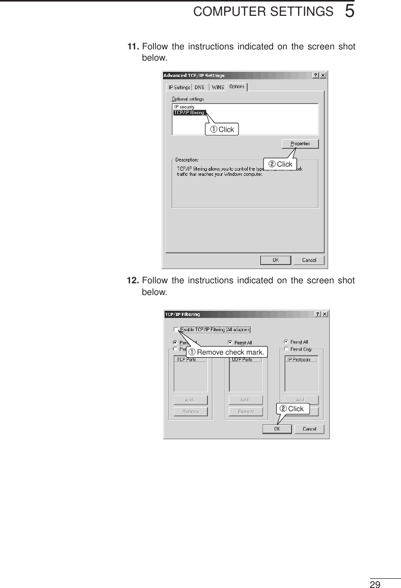
![COMPUTER SETTINGS5289. Click the [Options] tab and follow the instructions indi-cated on the screen shot below.qwClickClick10. Follow the instructions indicated on the screen shotbelow.qwClickClickÇ-3 Windows 2000 (Professional) (continued)](https://usermanual.wiki/ICOM-orporated/AP-3/User-Guide-130793-Page-36.png)
![COMPUTER SETTINGS53013. Click <OK> on the [Advanced TCP/IP Settings]screen (Step 11). The screen shown below is dis-played.• Follow the instructions indicated on the screen shotbelow.Click14. A message offering to restart the computer is dis-played. Click <No>.ClickÇ-3 Windows 2000 (Professional) (continued)* Select <No> because you will shut the computerdown instead.](https://usermanual.wiki/ICOM-orporated/AP-3/User-Guide-130793-Page-38.png)
![COMPUTER SETTINGS 53115. Click <Start> and select [Shut Down]. The followingscreen is displayed.• Follow the instructions indicated on the screen shotbelow.wqClickSelect “Shut down.”16. After shutting down the computer, proceed to Chapter6 (☞p. 37).](https://usermanual.wiki/ICOM-orporated/AP-3/User-Guide-130793-Page-39.png)
![COMPUTER SETTINGS532Ç-4 Macintosh OperatingSystemWhen using a Macintosh operating system, adjust theTCP/IP settings according to the procedure below.Since ICOM wireless LAN cards cannot be used withMacintosh computers, the settings explained hereare to prepare for a cable connection with the AP-3unit.1. Start up the computer.2. Open the [Apple Menu] and select [Control Panel].Then open the [TCP/IP] screen.• Follow the instructions indicated on the screen shotbelow.Select “Ethernet.”Select “Using DHCP server.”5-1 Network Settings (continued)[NOTE]* When the network settingsare changed, the previoussetting values will beerased. * This procedure is based onMac OS J1-8.6. The orderof the steps and thescreens themselves mayvary if a different version isused. Consult the Help filesof your Macintosh operat-ing system for assistance.* If a TCP/IP item is not included on the [ControlPanel], refer to the Help screen of the operating sys-tem or the instruction manual provided with theEthernet card for instructions regarding how to installthe TCP/IP protocol.3. Click the close-box button on the title bar.• The settings are saved and the [TCP/IP] screencloses.4. After the computer shuts down, proceed to Chapter 6(☞p. 37).](https://usermanual.wiki/ICOM-orporated/AP-3/User-Guide-130793-Page-40.png)
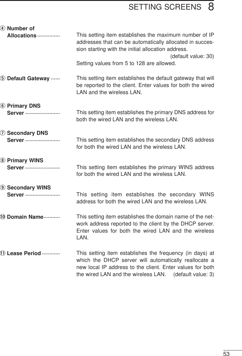
![COMPUTER SETTINGS 5335-2 Setting Tips ●Complete the settings described in this chapter andshut down the computer before proceeding to Chapter6 (☞p. 37).●Complete the settings described in Chapter 6 (☞p. 37)before connecting the AP-3 to a working LAN. ●When constructing a TCP/IP network, it is necessary toset the IP addresses of the computers that will be con-nected to the network. (☞p. 17).●A computer running Windows will acquire the local IPaddress from the AP-3 when Windows is started upand a computer using a Macintosh operating systemwill acquire the local IP address each time networkcommunications are begun (e.g., when the computeraccesses the internet or email). Make sure the AP-3 unit is turned on and “Use DHCPserver function” is set to “Yes” on the screen shown onpage 52. ●When the AP-3 unit attempts to allocate a local IPaddress to a computer and another computer (non-DHCP client for which local IP address was set manu-ally) is already using the same local IP address, theAP-3 unit will not detect the existence of the addressused by the other computer.●When [Routing Mode] (☞p. 51) is not used, the totalnumber of IP addresses that the AP-3 unit can allocateautomatically to both wireless and wired LAN comput-ers is a 5 to 128. When [Routing Mode] is used, the AP-3 unit can allocate 5 to 128 IP addresses to wirelessLAN computers and the same number to wired LANcomputers. The original factory setting for the numberof allocations is 30 for both wired and wireless LAN.(☞p. 53)Avoid overlapping between the IP addresses of clients(including clients having a wireless connection) con-nected to the same network and the range of IPaddresses that the AP-3 unit can automatically allocateto computers.](https://usermanual.wiki/ICOM-orporated/AP-3/User-Guide-130793-Page-41.png)
![COMPUTER SETTINGS5345-3 Checking the Network SettingsUse one of the following procedures (depending onthe operating system) to check, release, or reaac-quire IP address settings that were obtained auto-matically. ■Windows 95 and 98For Windows 95 and 98, use the winipcfg.exe file in theWindows folder.[Steps]1. Click <Start> and select [Run].2. Type “winipcfg” into the text box and press the [Enter]key. • The following screen will appear when the applicationstarts up:3. Click the ▼button on the right side of the text box andselect the name of the Ethernet card being used.Check or release the setting values, or reacquire thesettings. ●Adapter address : MAC address of Ethernet card](https://usermanual.wiki/ICOM-orporated/AP-3/User-Guide-130793-Page-42.png)
![COMPUTER SETTINGS 535■Windows NT 4.0 (Work Station) or Windows 2000 (Professional)Run [ipconfig] from the command prompt screen.[NOTE]For more information, run[ipconfig/?] and read the helpinformation displayed.Windows NT 4.0 or Windows 2000 will prepare an IP address anddisplay the [Command Prompt] screen when the IP address hascontinuously failed to be obtained from the DHCP server for a cer-tain amount of time. When this occurs, the computer does not havea proper connection with the AP-3. Check the connection with theAP-3 and the TCP/IP settings of the computer.](https://usermanual.wiki/ICOM-orporated/AP-3/User-Guide-130793-Page-43.png)
![COMPUTER SETTINGS536■Macintosh OperatingSystemThe network settings can be checked from the TCP/IPsettings screen (☞p. 32). The screen shown below is dis-played when the [Setting Method] is set to “Browse DHCPserver.”[NOTE]The computer will not obtainthe network setting valuesfrom the DHCP server untilnetwork communications(e.g., accessing the internetor email) have actually beenconducted. Conduct somesort of network communica-tions before checking thenetwork settings.[Checking the Mac address]1. Select [Control Panel] from the [Apple Menu]. Theopen [Apple Talk]. One of the following two screens isdisplayed.* To arrange for the screen on the right to be shown,select [User Modes] from the [Edit] menu (on themenu bar) and select the [Specify details] option.2. Select [Ethernet] for the [Passageway].3. Display the screen shown below by selecting [ShowInformation] from the [File] menu when working withthe left-hand screen shown above or by clicking the<Information> button when working with the right-handscreen shown above. MAC address](https://usermanual.wiki/ICOM-orporated/AP-3/User-Guide-130793-Page-44.png)
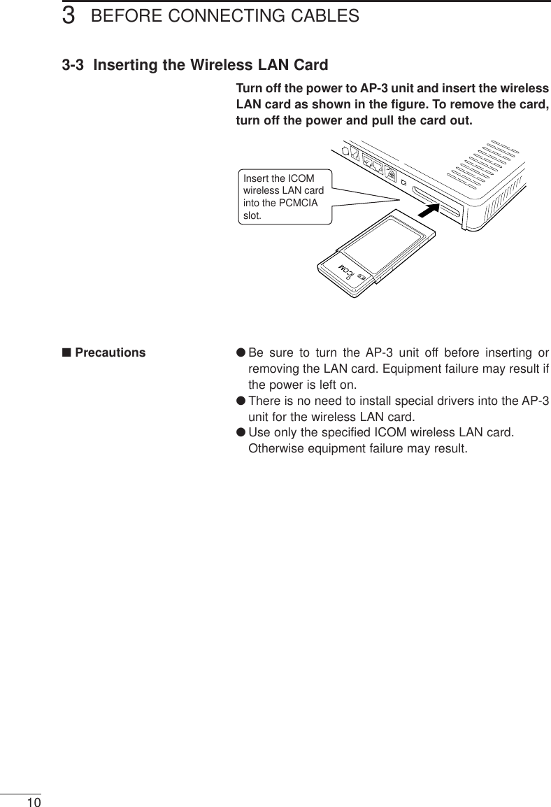
![AP-3 SETTINGS 6376-1 Before Getting StartedDisconnect the network computers from the AP-3 unitif you are starting up the AP-3 unit for the first timeafter purchasing it or after initializing all setting data.Connect only the computer than will be used for toadjust the settings. The connection can be wired orwireless.If the AP-3 unit is connected to a working network with-out changing the original factory settings, IP addressconflicts and other network problems may occur.6-2 Preparing to Adjust the Settings with a Cable ConnectionÅConnections See “4-1 Connecting to a Computer” (☞p. 14) regardinghow to connect the computer to the AP-3.Setting terminal AP-3Ethernet cableıStarting the AP-3and computer1. After connecting the cable, connect the provided ACadapter to the DC jack of the AP-3 and plug it into anoutlet. The AP-3 unit will power on. (☞section 4-3, p.16)• At first all lamps on the front panel will illuminate, thenonly the [POWER] lamp will remain on.2. Start up the computer.• If the connection is established normally, the [LAN]lamp (☞p. 6) on the front panel of the AP-3 will illu-minate.* If the [LAN] lamp does not illuminate set the[HUB/PC] switch to [PC]. (☞pp. 6 and 14)[IMPORTANT]When the computer is connected to the AP-3 through a hub, do notstart up any computer other than the computer being used to adjustthe settings (setting terminal) until the settings are completed.[NOTE]If possible, use a cable connection between the AP-3 and the com-puter used to adjust the settings.](https://usermanual.wiki/ICOM-orporated/AP-3/User-Guide-130793-Page-45.png)
![AP-3 SETTINGS6386-3 Preparing to Adjust the Settings with a Wireless Connection[NOTE]• If an ICOM SL-1100 wire-less LAN card is used withthe AP-3, the same modelof wireless LAN card (SL-1100) must be used withthe computer being used toadjust the settings.• A Macintosh computer can-not be used as a wirelessterminal.ÅConnections See “4-1 Connecting to a Computer” (☞p. 14) regardinghow to set up the wireless connection between the com-puter and the AP-3.Wireless LAN cardWireless LAN cardSetting terminal AP-3The items listed below need to be confirmed in orderto establish a wireless connection between the set-ting terminal and the AP-3 unit. See the instructionmanual provided with your ICOM wireless LAN cardfor details.●Make sure the driver for the ICOM wireless LAN card isinstalled.●Check the [ESS ID] and [Network Mode] of the wirelessLAN card.●Check the TCP/IP protocol settings.When the AP-3 will be connected to a working net-work, check the following items in addition to thoselisted above:●Check the Microsoft Network Sharing Service.●Check the identification information (work group).●Check the shared folders.ıSetting terminal settingsı-1 Network Mode The [Network Mode] of the AP-3 is factory set to sup-port the kind of wireless access point function (☞p.45) illustrated above. Make sure the wireless LANcard used with the setting computer is also set to thecorrect mode (e.g., “Infrastructure” if using an SL-1100 or SL-1105 LAN card) for connecting to anaccess point. (☞p. 39)[NOTE]If you are using Windows2000, “Microsoft NetworkSharing Service” will beexpressed as “MicrosoftNetwork File and PrinterSharing”[NOTE]If you are using an ICOM SL-1100 wireless LAN card,[Network Mode] will be called[Wireless station type].The computer will not be able to establish a wirelessconnection with the AP-3 unit if the wireless LAN cardused with the setting terminal is set to the mode forcommunication between wireless terminals (e.g.,“Adhoc” mode if using an SL-1100 or SL-1105 LANcard).](https://usermanual.wiki/ICOM-orporated/AP-3/User-Guide-130793-Page-46.png)
![AP-3 SETTINGS 639ı-2 ESS ID The [ESS ID] is used to prevent unauthorized accessto the wireless network group.The [ESS ID] of both AP-3 unit and the wireless LAN cardare factory set to “LG” (upper gas letters).The computers that will have a wireless connection withthe AP-3 and the other computers in the same networkgroup must have the same [ESS ID]. Otherwise thedevices will not be able to communicate.ı-3 Checking the settingsCheck the [Network Mode] and [ESS ID] settingsusing the setting screen.Be sure to restart the computer if you change any set-ting values. Otherwise the new settings will not be effec-tive and the computer will not be able to make the wire-less connection with the AP-3 unit.However, restarting is not necessary if the Utility provid-ed with the LAN card is used to change the settings.See the instruction manual provided with the wirelessLAN card for more information.[Windows 98]Click <Start> and select [Control Panel] from the[Settings] menu. Double click the [Network] icon. Thendouble click “Icom SL-1100 Wireless LAN Adapter (PCM-CIA 3V)” in the list of installed components.Select the [Advanced] tab on the adapter propertiesscreen. The screen will appear as shown below.[NOTE]• If the driver for the ICOMwireless LAN card has notbeen installed in the com-puter, “Icom SL-1100Wireless LAN Adapter(PCMCIA 3V)” will not beincluded in the list of net-work components and it willnot be possible to displaythe screen shown to theright (illustrating Windows98).See the instruction manualprovided with the wirelessLAN card for more informa-tion about the settingscreen and installing thedriver.• If you are using Windows95, the items displayedunder [Property] will be dif-ferent.[NOTE]If you are using an ICOM SL-100 wireless LAN card, [ESSID] will be called [Net key].](https://usermanual.wiki/ICOM-orporated/AP-3/User-Guide-130793-Page-47.png)
![AP-3 SETTINGS6406-3 Preparing to Adjust the Settings with a Wireless Connection (continued)ı-3 Checking the settings (continued)[Windows NT 4.0]Click <Start> and select [Control Panel] from the[Settings] menu. Then double click the [Network] icon andselect the [Adapters] tab. Finally, double click “Icom SL-1100 Wireless LAN Adapter (PCMCIA 3V)” in the listunder [Network adapters].The screen will appear as shown below.[Windows 2000]Click <Start> and select [Dial-Up Networking] from the[Settings] menu. Double click the appropriate [Local AreaConnection] icon on the [Dial-Up Networking] screen andthen click <Properties>. Click <Configuration> and selectthe [Advanced] tab. The screen will appear as shown below.[NOTE]If the driver for the ICOMwireless LAN card has notbeen installed in the comput-er, “Icom SL-1100 WirelessLAN Adapter (PCMCIA 3V)”will not be included in the listof network adapters and itwill not be possible to displaythe screen shown to theright.See the instruction manualprovided with the wirelessLAN card for more informa-tion regarding installing thedriver.](https://usermanual.wiki/ICOM-orporated/AP-3/User-Guide-130793-Page-48.png)
![AP-3 SETTINGS 641ÇStarting the AP-3and computer1. After completing the setting terminal settings (☞p. 38),insert the wireless LAN card into the PCMCIA slot ofthe AP-3 unit.2. Connect the provided AC adapter to the DC jack of theAP-3 and plug it into an AC outlet (☞section 4-3, p.16). The AP-3 will power on.• At first all lamps on the front panel will illuminate, thenonly the [POWER] lamp will remain on.3. Start up the computer (setting terminal). Do not startany other computers in the network.* If the connection is established normally, thelamp (☞p. 6) on the front panel of theAP-3 will illuminate.* The green lamp of the wireless LAN card insertedinto card slot of the computer (setting terminal) willflash continuously. The red lamp will flash when thecomputer accesses the AP-3 unit.* If the lamp on the front panel does notilluminate, check the [Network Mode] and [ESS ID]settings of the computer or restart computer. (☞pp.38, 39 and 40)* If the lamps of the wireless LAN card inserted into thecard slot of the computer do not illuminate or do notbehave as described above, check if the driver isinstalled properly.[IMPORTANT]When the computer is connected to the AP-3 through a hub, do notstart up any computer other than the computer (setting terminal)being used to adjust the settings until the settings are completed.](https://usermanual.wiki/ICOM-orporated/AP-3/User-Guide-130793-Page-49.png)
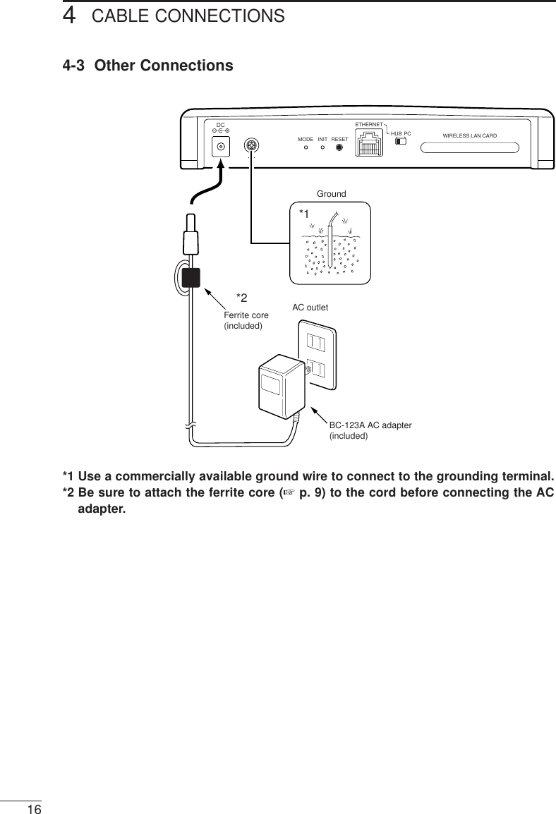
![AP-3 SETTINGS6426-4 Accessing the Setting ScreenAfter connecting the computer (setting terminal) tothe AP-3 unit according to the instructions in section6-2 or 6-3, make sure you can access the settingscreen of the AP-3 using the web browser of the com-puter.Install a web browser into the computer if it does notalready have one.1. Open the web browser of the setting terminal.2. Designate the IP address of the AP-3 unit as the URL.• http://192.168.0.1 (original factory setting)3. When the setting terminal gains access to the AP-3unit, the [Wireless LAN Setting] screen is displayed.* If the setting screen is not displayed, check the set-tings, connections, and IP address settings (☞p. 34)of the setting terminal. Restart the setting terminaland try to access the AP-3 again.[Wireless LAN Setting Screen] qSetting screen selection area ·········· This area displays the titles of all AP-3 setting screens.Click the title of the desired setting screen to open it.wSetting screen display area·············· This area displays the selected setting screen.e<Save> button·········· Click this button to save changes made to the data dis-played on the setting screen.](https://usermanual.wiki/ICOM-orporated/AP-3/User-Guide-130793-Page-50.png)
![AP-3 SETTINGS 643r<Cancel> button ······ Click this button to cancel any changes and return thesetting data to its original state (i.e., state before changeswere made). If the <Save> button has been pressed, thesettings will not return to their original state.t<Save and Restart>button ······················· Click this button to save the setting changes and restartthe AP-3 unit.* After the settings have been saved, a message sug-gesting restarting the unit will be displayed next to thisbutton if restarting is required. Be sure to click this but-ton when this occurs.yVersion information··············· This area shows the version of the firmware (☞p. 66).This manual assumes Version 1.0 is being used.6-5 Testing the OperationSet up the connection arrangement shown below andcheck if a wireless connection with the AP-3 can bemade.* The settings of the AP-3 unit are assumed to be originalfactory settings.PCEthernet cableWireless LAN cardWireless LAN cardWired terminalAP-31. Insert the wireless LAN card into the AP-3 unit. (☞p.10)2. Connect the provided AC adapter to the AP-3 unit.• At first all lamps on the front panel will illuminate, thenonly the [POWER] lamp will remain on.3. Start up the wired terminal (connected with an Ethernetcable).• The [LAN] lamp (☞p. 6) on the front panel of the AP-3 will illuminate.4. Make sure you can access the setting screen of theAP-3 from the wired terminal. (☞p. 42)5. Create a test folder and set the shared folder permis-sion so that the folder can be shared.·············································Continued on following page](https://usermanual.wiki/ICOM-orporated/AP-3/User-Guide-130793-Page-51.png)
![AP-3 SETTINGS6446-5 Testing the Operation (continued)6. Start up the wireless terminal (in which a wireless LANcard has been inserted). (☞6-3, p. 38).• If the connection is normal, the lamp(☞p. 6) on the front panel will illuminate.7. Make sure you can access the setting screen of theAP-3 from the wireless terminal (☞p. 42).8. Create a test folder and set the shared folder permis-sion so that the folder can be shared.9. Double click the [Network Computer] icon on both thewired terminal and the wireless terminal. The wirelessaccess point is functioning properly if both computersdisplay an icon for the other computer.* If using Windows 2000, [Network Computer] is called[My Network].10. From each computer (wired and wireless), doubleclick the icon for the other computer. The newly cre-ated test folder should appear.11. After completing these steps, refer to Chapter 8 andset up the AP-3 so it can be used in the working net-work. Then connect the AP-3 to the network.](https://usermanual.wiki/ICOM-orporated/AP-3/User-Guide-130793-Page-52.png)
![WIRELESS FUNCTIONS 745The AP-3 unit can function in the following two waysto construct a wireless network:• Wireless access point function (☞section 7-1 below)• Roaming function for roaming with a wireless terminal(☞section 7-2, p. 46)* When a wireless transmission speed of 11 Mbps isused, the transmission range is roughly 30 m indoorsand 70 m outdoors (line of sight). [NOTE]A Macintosh computer cannot be used as a wirelessterminal.7-1 Wireless Access Point FunctionThe wireless access point function refers to using theAP-3 unit to construct a local area network whereinwireless terminals can communicate with each otheras well as with wired terminals connected to the AP-3 via an Ethernet cable. ■Schematic illustrationAP-3Wired LANLANUp to 256 wireless terminals can be connected.Wireless transmission area Wireless transmission areaWireless LAN cardEthernet LANEthernet LAN](https://usermanual.wiki/ICOM-orporated/AP-3/User-Guide-130793-Page-53.png)
![WIRELESS FUNCTIONS7467-2 Roaming FunctionEthernet LANWireless transmission areaAP-3 AP-3 AP-3Moves MovesSwitches AP-3 unitsSwitches AP-3 unitsWireless LAN cardWireless LAN cardThe roaming function refers to installing multiple AP-3 units along an Ethernet LAN so that the wirelesstransmission areas overlap. This arrangement allowswireless terminal to maintain communications withthe Ethernet LAN while moving among the wirelesstransmission areas. In short, this function allows thewireless transmission area to be expanded.■Schematic illustration■Roaming functionprecautions●Overlapping of IP addresses can be avoided by settingup only one of the AP-3 units so that the DHCP serverfunction is enabled. ●Within the mobile wireless transmission area (roamingarea), all wireless terminals and AP-3 units for whichthe roaming function will be used must use the same[ESS ID] setting.Wireless terminals set to a different [ESS ID] will not beable to communicate with the AP-3 units.●The wireless LAN terminals, including those in theroaming area, will operate as part of the same networkgroup as wired LAN terminals. Therefore, routing mode(☞p. 51) cannot be used when the roaming function isused.●When SL-1100 or SL-1105 LAN cards are used androaming is conducted using the same channel for allLAN cards, the transmission speed may decline in theinterference areas where the signals from two wirelessaccess points (i.e., AP-3 units) can be received simul-taneously. To avoid interference completely, set thechannels of the AP-3 units at least four channels apart.●Connect the AP-3 units in a cascade arrangement byconnecting them through a hub using Ethernet cable.](https://usermanual.wiki/ICOM-orporated/AP-3/User-Guide-130793-Page-54.png)
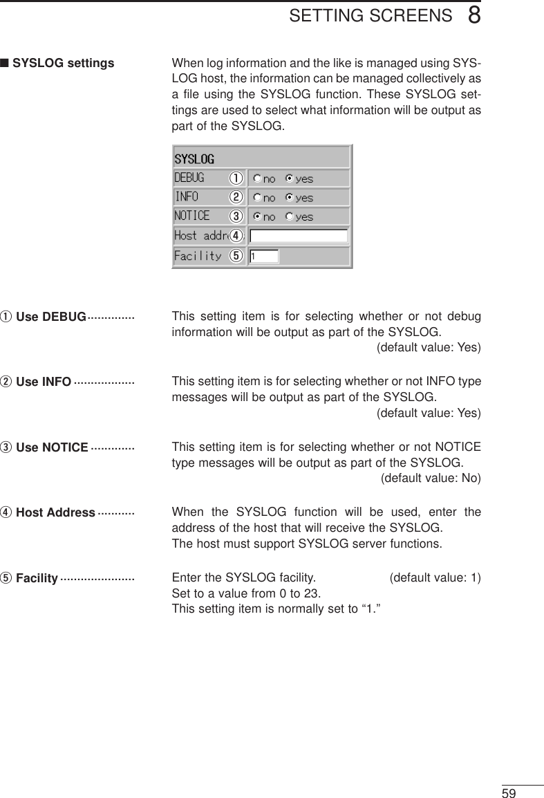
![SETTING SCREENS 8478-1 [Wireless LAN Settings] Screen■Wireless LAN settingswqeq<SL-1100 or SL-1105advanced settings>button ······················· Click this button to open an advanced LAN card settingscreen when an SL-1100 or SL-1105 wireless LAN card isused with the AP-3.wESS ID······················· This setting item is used to establish an ID to preventunauthorized access to the wireless LAN connected tothe AP-3 unit. A wireless connection can only be madebetween AP-3 units having the same ESS ID or betweenan AP-3 unit and a wireless terminal having the sameESS ID. Setting changes will not take effect until the AP-3 unit isrestarted.When entering the ESS ID, use up to 31 arbitraryalphanumeric characters. Upper and lower case are dis-tinguished. (Default setting: LG)Typed characters are displayed as asterisks (*).(Display example: **)eESS ID ConfirmationReentry ····················· This setting item is for reentering the ESS ID to makesure it is entered correctly with no typographical errors.Be careful to distinguish between upper and lower caseletters. (Display example: **)■SL-1100 or SL-1105advanced settingsqwertyui[NOTE]Only when the channel set-ting is changed does the AP-3 unit need to be restarted.qChannel ···················· This setting item is used to set the wireless transmissionchannel used for the wireless connection of the AP-3.(default value: 14)* Wireless terminals using an SL-1100 or SL-1105 wire-less LAN card will automatically detect the channel set-ting of the AP-3.·············································Continued on following pagee.g. SL-1100](https://usermanual.wiki/ICOM-orporated/AP-3/User-Guide-130793-Page-55.png)
![SETTING SCREENS8488-1 [Wireless LAN Settings] Screen (continued)■SL-1100 or SL-1105 advanced settings (continued)wSecurity Level·········· This setting item is used to set the degree of data encryp-tion used to protect the data transmitted over the wirelessnetwork. (default setting: None)The AP-3 uses WEP (wired equivalent privacy) encryp-tion.Except for [WEP Key], all setting items under [SecurityLevel Custom Settings] are set automatically according tothe security level (Low, Medium, or High) selected here.When this setting item is set to “Custom” the setting items(except WEP Key) under [Security Level CustomSettings] can be set arbitrarily.* We recommend using the same security level fordevices that will be communicating with each other.However, a wireless terminal with a security setting of“Medium” can communicate with another wireless orwired terminal through an AP-3 unit with a security set-ting of “Low.”eKey Generator·········· This setting item is used to enter a character string forgenerating the key used for encryption and decryption. Typed characters are displayed as asterisks (*).(Display example: **)The keys generated from the entered character string aredisplayed in the WEP Key text boxes under [SecurityLevel Custom Settings]. * Enter the same character string (arbitrary combinationof alphanumeric characters and symbols for whichupper and lower case letters are distinguished) as theother devices with which AP-3 will be communicating. Ifdifferent character strings are used, the encrypted datacannot be decrypted.rDecryption ofReceived Packets···· This setting item is related to the decryption of receivedpackets. Select from among “Yes”, “No” and “Yes (destroyunencrypted packets)” (default value: No)tEncryption of Trans-mitted Packets········· This setting item is related to the encryption of receivedpackets. Select “Yes” or “No.” (default value: No)·············································Continued on following page](https://usermanual.wiki/ICOM-orporated/AP-3/User-Guide-130793-Page-56.png)
![SETTING SCREENS 149yWEP Factor ·············· This setting item is used to establish the security level. “0”indicates the highest degree of security.(default value: 0)The encryption levels are as follows:“0”= updates internal encryption key for every packet“1”= updates internal encryption key every five packets“2”= updates internal encryption key every ten packets“3”= updates internal encryption key every fifty packetsuNumber ofEncryption Bits········ This setting item is used to select the number of encryp-tion bits. (default value: 64)When “64 bits” is selected, the last 40 bits of the keys areshown in the [WEP Key] text boxes. When “128 bits” is selected, the last 104 bits of the keysare shown in the [WEP Key] text boxes. ( The leading 24 bits are not displayed.iWEP Key··················· When 64-bit encryption is selected, the keys generatedfrom the character string entered into the [Key Generator]text box are displayed in text boxes 1, 2, 3, and 4 in 40-bit segments. When 128-bit encryption is selected, thekeys are displayed in 104-bit segments. Only the selected key (1, 2, 3, or 4) is used for encryption.Select a key by putting a check in the adjacent check box.The other device can only decrypt the signal from the AP-3 when it is encrypting with one of the four keys (1, 2, 3,or 4) shown here. * The keys can also be entered directly into the WEP keytext boxes (1, 2, 3, and 4). When this is done, a charac-ter string will not be displayed in the [Key Generator]text box.](https://usermanual.wiki/ICOM-orporated/AP-3/User-Guide-130793-Page-57.png)
![SETTING SCREENS8508-1 [Wireless LAN Settings] Screen■MAC address security settingsqwerqUse MAC AddressSecurity ····················This setting item is used to select whether or not to limitwireless connections with this AP-3 unit to those wirelessterminals having one of the MAC addresses registeredhere. (default value: No)Setting changes will not take effect until the AP-3 unit isrestarted.wMAC Address on theWireless LAN card···When the wireless LAN card inserted into the AP-3 isproperly recognized, the MAC address registered on thewireless LAN card is displayed here.eMAC Address··········· When the MAC Address Security function is used, the AP-3 unit can communicate with other ICOM network devicesfitted with a wireless LAN card whose MAC address set-ting matches one of the MAC addresses registered here.* A maximum of 256 different MAC addresses can be reg-istered.* Enter 12 alphanumeric characters for each address.* After entering the address, click <Add>. Them makesure the new address appears in the [Current Registry]. * Hyphens are not recognized as part of the address.Thus, the following two entries represent identicaladdress values:11-11-11-22-33-33 111111223333* See section 5-3 (☞p. 34) for instructions on how tocheck the MAC address of a wireless LAN card.r<Delete> button ······· This button is used to delete a previously registered MACaddress. When no MAC addresses are registered, thisbutton is not displayed.](https://usermanual.wiki/ICOM-orporated/AP-3/User-Guide-130793-Page-58.png)
![SETTING SCREENS 851■Routing mode setting8-2 [AP-3 Network Settings] ScreenUsing Routing Mode This setting item is used to set whether or not routing willbe used between the wired LAN and the wireless LAN.(default setting: No)It is necessary to restart the AP-3 unit to activate any set-ting changes. * When “No” is selected, the wired LAN and the wirelessLAN are handled as though they are in the same subnet(i.e., same network) and, therefore, the roaming func-tion (☞p. 46) can be used. In this case, the IP addressand subnet mask settings under [Wired LAN] on the[AP-3 Network Settings] screen are used for the wire-less LAN.When “Yes” is selected, the wired LAN and the wirelessLAN are handled as though they are in different subnets(i.e., separate networks). In this case, the IP addressand subnet mask settings under [Wireless LAN] on the[AP-3 Network Settings] screen are used for the wire-less LAN.■AP-3 IP address settingsqwqIP address •••••••••••• This setting item is used to set the wired LAN and wire-less LAN IP addresses.●Wired LAN default setting : 192.168.0.1●Wireless LAN default setting : 192.168.1.1Setting changes will not take effect until the AP-3 unit isrestarted.wSubnet mask•••••••••• This setting item is used to set the wired LAN and wire-less LAN subnet masks.●Wired LAN default setting : 255.255.255.0●Wireless LAN default setting : 255.255.255.0Setting changes will not take effect until the AP-3 unit isrestarted.When the [Routing Mode Setting] is set to “No” (default),the AP-3 unit will operate using the IP address and sub-net mask entered under [Wired LAN] for the wirelessLAN.](https://usermanual.wiki/ICOM-orporated/AP-3/User-Guide-130793-Page-59.png)
![SETTING SCREENS8528-2 [AP-3 Network Settings] Screen (continued)[NOTE]The AP-3 unit must berestarted before any of thesettings on this screen willtake effect.■DHCP server settingsqwertyuio!0!1qUse DHCP ServerFunction ··················· This setting item is used to set whether the AP-3 unit willbe used as a DHCP server or not. (default value: Yes)When the AP-3 is used as a DHCP server, the followinginformation regarding the DHCP server clients can be setautomatically:●IP address●Subnet mask●Default gateway●DNS server●WINS server●Domain namewInitial Allocation IPAddress ···················· This setting item is for setting the initial IP address thatwill be used when the AP-3 unit allocates IP addresses tocomputers connected with either a wired or a wirelessconnection.●Default value for wired LAN side :192.168.0.10●Default value for wireless LAN side :192.168.1.10eSubnet Mask ············ This setting item is the subnet mask corresponding to theallocation starting IP address. (default value: 255.255.255.0)·············································Continued on following page](https://usermanual.wiki/ICOM-orporated/AP-3/User-Guide-130793-Page-60.png)
![SETTING SCREENS8548-2 [AP-3 Network Settings] Screen (continued)■Static DHCP serversettingsThis section of the [AP-3 Network Settings] screen isused to specify the wired and wireless terminals to whichIP addresses will be automatically allocated using theDHCP server function. The computers are registeredaccording to MAC address and IP address. * Enter 12 alphanumeric characters for each MACaddress. * Hyphens are not recognized as part of the address.Thus, the following two entries represent identical MACaddresses:11-11-11-22-33-33 111111223333* Up to 16 wired and wireless terminals can be registered.The IP addresses registered here must be outside therange of IP addresses that can be allocated by theDHCP server function.* After typing the MAC address and IP address, click<Add> under “Wired” or “Wireless” and make sure thenew addresses have been registered under [CurrentRegistry].[NOTE]The AP-3 unit must berestarted before any of thesettings on this screen willtake effect.](https://usermanual.wiki/ICOM-orporated/AP-3/User-Guide-130793-Page-62.png)
![SETTING SCREENS 8558-3 [Routing Settings] Screen■RIP settingWhen RIP is used, the AP-3 exchanges routing informa-tion with nearby routers and access points to dynamical-ly create a communication path. RIP packets are broad-cast approximately every 30 seconds using the broadcastaddresses of those routers and access points.(default value: Yes)A setting change will not take effect until the AP-3 unit isrestarted.■IP routing informationThis table displays information regarding which terminal,access point, or router the packet should be distributed towhen the AP-3 transmits a packet. Paths added using the[Static Routing Settings] (☞p. 57) are also displayedhere.q w ertyqDestination··············· This column shows the destination IP address of thepacket being routed.wNet Mask··················· This column shows the net mask corresponding to thedestination IP address of the packet being routed.eGateway···················· This column shows the gateway corresponding to thedestination IP address of the packet being routed.·············································Continued on following page](https://usermanual.wiki/ICOM-orporated/AP-3/User-Guide-130793-Page-63.png)
![SETTING SCREENS8568-3 [Routing Settings] Screen (continued)■IP routing information (continued)rNet····························· This item displays added IP routing information in the[Network Interface List]. • InterfaceThis column shows the transfer destination interfacecorresponding to the destination IP address of the pack-et being routed.• IP AddressThis column shows the IP address of the transfer desti-nation. • Net MaskThis column shows the net mask of the transfer desti-nation.tCreation Type··········· This column shows how the routing information wasmade.• staticIndicates that the routing information was created usinga static (defined) route.• ripIndicates that the routing information was created usinga dynamic (automatically generated) route.• miscIndicates that the routing information is related to thebroadcast.yMetric························ This column displays the number of routers and accesspoints (or gateways) that the packet will pass throughbefore reaching its destination.](https://usermanual.wiki/ICOM-orporated/AP-3/User-Guide-130793-Page-64.png)
![SETTING SCREENS 8578-3 [Routing Settings] Screen (continued)■Static routing settingsThis table is used to specifically define the routing path ofa packet. Up to 20 paths can be registered.* After entering a path, click <Add> and make sure thepath is displayed in the [Current Registry]. The settingdata should also appear on the [IP Routing Information]screen.q w ertqPath··························· • localSelect “local” when the [Routing Mode] (☞p. 51) is notused. Indicates that the routing information to be regis-tered is for the LAN.• ethernetSelect “ethernet” when the [Routing Mode] is used.Indicates that the routing information to be registered isfor the wired LAN.• wirelessSelect “wireless” when the [Routing Mode] is used.Indicates that the routing information to be registered isfor the wireless LAN.wDestination ·············· Enter the IP address of the target destination in accor-dance with the selected path (ethernet, wireless, or local).eNet Mask··················· Enter the net mask corresponding to the IP address of thetarget destination in accordance with the selected path (ethernet, wireless, or local).rGateway···················· Enter the gateway for the transfer destination (router oraccess point) of the packet to be routed.tMetric Value·············· Enter the number of routers and access points (or gate-ways) that the packet will pass through before reachingits destination.Values from 0 to 16 may be entered.The AP-3 interprets a small number as indicating that thecircuit has a high transfer capacity.](https://usermanual.wiki/ICOM-orporated/AP-3/User-Guide-130793-Page-65.png)
![SETTING SCREENS8588-4 [AP-3 Management Settings] Screen■Manager ID settingsEnter an arbitrary name for the network manager usingup to 31 alphanumeric characters. Upper and lower caseletters are distinguished. (Example ID: AP-3)A user name will be requested the next time the AP-3 unitis accessed after completing this setting. Enter this man-ager ID.wManager Password·· Enter an arbitrary password using up to 31 alphanumericcharacters. Upper and lower case letters are distin-guished. (Display example: ****)Typed characters will appear as asterisks (*).A password will be requested the next time the AP-3 unitis accessed after completing this setting. Enter this man-ager password.ePassword Confirma-tion Reentry ············· This setting item is for reentering the manager passwordto make sure it is entered correctly with no typographicalerrors. (Display example: ****)qweqManager ID···············](https://usermanual.wiki/ICOM-orporated/AP-3/User-Guide-130793-Page-66.png)
![SAVING AND UPLOADING SETTING DATA9609-1 [Save Settings] ScreenThe [Save Settings] screen is used to copy settingdata from the AP-3 to a floppy disk or the hard disk ofa computer and to upload setting data from a com-puter to the AP-3.q w erq<Register to AP-3>button ······················· This button is used to copy the setting data shown on the[Save Settings] screen to the setting screen of the AP-3.w<Undo> button········· This button is used to undo any changes made to the set-ting data shown on the [Save Settings] screen and returnthe data to the state it was in when the file was firstopened.e<Return to Menu>button ······················· This button is used to return to the [Wireless LANSettings] screen.rDisplay area ············· When the [Save Settings] screen is opened from the AP-3 setting screen, the current setting data is displayed inthis area.When the [Save Settings] screen is opened from a datafile according to the procedure in “9-3 Uploading SettingData” (☞p. 62), the setting data stored in the data file isdisplayed.](https://usermanual.wiki/ICOM-orporated/AP-3/User-Guide-130793-Page-68.png)
![SAVING AND UPLOADING SETTING DATA 9619-2 Saving Setting DataFollow the procedure below to save the current set-ting data as an HTML file onto a floppy disk or thehard disk of the computer being used to access theAP-3. 1. Connect a setting terminal (wired or wireless) to theAP-3.2. Start up the web browser of the setting terminal.3. Access the setting screen of the AP-3.4. Click [Save Settings] in the setting screen selectionarea.• The [Save Settings] screen is displayed as shownbelow.5. Select [Save as] from the [File] menu of the web brows-er.6. Designate the directory in the [Save in] text box andenter a filename in the text box. 7. Select [HTML file] under [Save as type]. * Select JIS if your browser offers a selection of kanjicodes for the file. 8. Click the <Save> button. • The setting data is stored in the designated location.* The file extension will be htm or html.* The file will not have an extension if saved on aMacintosh.[Note]This explanation is based onInternet Explorer 5.0 forWindows.](https://usermanual.wiki/ICOM-orporated/AP-3/User-Guide-130793-Page-69.png)
![SAVING AND UPLOADING SETTING DATA9629-3 Uploading Setting DataFollow the procedure below to upload setting datafrom a computer to the AP-3.1. Connect a setting terminal (wired or wireless) to theAP-3.2. From the setting terminal, double click the icon of thestored data file.• The [Save Settings] screen is displayed as shownbelow.3. Click the <Register to AP-3> button.• The setting data is uploaded and the AP-3 restarts.4. Check that the correct setting data has been uploadedand close the setting screen.■Precautions regarding editingWhen editing the network IP address or other setting inthe display area, change the other related setting valuesat the same time. * Read “General Precautions” (☞p. 4) regarding editingthe setting data. Bear in mind that the results of any set-ting changes will be on your own responsibility.](https://usermanual.wiki/ICOM-orporated/AP-3/User-Guide-130793-Page-70.png)
![SETTING DATA INITIALIZATION 1063There may be times when you wish to readjust thesettings from the beginning or delete existing settingdata, such as when changing the network configura-tion. The setting data can be returned to the originalfactory settings using one of the three methods (Å,ı, or Ç) listed below. This chapter explains Åand ıonly.ÅUse the <INIT> button (☞p. 63)ıUse the setting screen (☞p. 65).ÇUse the Utility (☞p. 67).* To use the Utility, install it from the included UtilitySoftware disks. See “12 Utility Software” (☞p. 67) forinstructions regarding how to install the Utility.ÅUsing the <INIT> buttonUse the following procedure to initialize the settingdata in situations where you cannot access the AP-3setting screen, such as when the current IP addresssetting of the AP-3 is unknown. 1. Disconnect all network devices except the AP-3 unitand the setting terminal (wired or wireless) that will beused to conduct the initialization. 2. Hold down the <INIT> button. Then supply power tothe AP-3 unit or lightly press and release the <RESET>button. • The [LAN] lamp and the lamp will flashin unison.3. Release the <INIT> button when the <POWER> indi-cator lamp starts flashing.• The <POWER> lamp will continue to flash slowlywhile operating in [Setting Initialization Mode].4. Start up the setting terminal. 5. Open the web browser of the setting terminal and adesignate the original factory-set IP address (☞p. 42)of the AP-3 in the URL text box. • The [Initialize mode] screen is displayed.](https://usermanual.wiki/ICOM-orporated/AP-3/User-Guide-130793-Page-71.png)
![SETTING DATA INITIALIZATION1064ÅUsing the [INIT] button (continued)6. Click the <Initialize> button on the [Setting InitializationMode] screen.• The following screen is displayed:7. Click the <Restart> button. • While the AP-3 unit is restarting, the following mes-sage is displayed:8. The initialization is complete when the <POWER>lamp stops flashing and the [Wireless LAN Settings]screen is displayed.](https://usermanual.wiki/ICOM-orporated/AP-3/User-Guide-130793-Page-72.png)
![SETTING DATA INITIALIZATION 1065ıUsing the settingscreenUse the initialization procedure described belowwhen the current IP address is known and the AP-3setting screen can be accessed. This procedure isconducted from the [Initialize Settings] screen andallows the scope of the initialization to be selected.1. Disconnect all network devices except the AP-3 unitand the setting terminal (wired or wireless) that will beused to conduct the initialization. 2. Start up the setting terminal. 3. Open the web browser of the setting terminal. 4. Designate the original factory-set IP address (☞p. 42)in the URL text box and access the AP-3 settingscreen.5. Click [Initialize Settings] in the setting screen selectionarea (☞p. 42).• The [Initialize Settings] screen is displayed.6. Select the radio button next to the desired initializationoption (see below for details).7. Click the [Initialize] button.• While the AP-3 unit is restarting, the following mes-sage is displayed.8. The initialization is complete when AP-3 unit hasrestarted and the [Wireless LAN Settings] screen isdisplayed.■Regarding initializa-tion options• Initialize all settingsThis option initializes all setting data adjusted from thesetting screen.• Initialize wireless settingsThis option initializes all settings that can be adjustedfrom the [Wireless LAN Settings] screens (☞section 8-1, pp. 47 to 50). Access the [Wireless LAN Settings]screens by clicking [Wireless LAN Settings] in the set-ting screen selection area (☞p. 42).](https://usermanual.wiki/ICOM-orporated/AP-3/User-Guide-130793-Page-73.png)
![UTILITY SOFTWARE 1267This chapter explains how to use the Utility softwareprovided on the Utility Software disks, which areincluded in the AP-3 package.12-1 About the UtilityThe Utility is a software application used to initializethe setting data and update the firmware of the AP-3unit. Install the Utility software in a computer having one of thefollowing operating systems.●Windows 95, Windows 98●Windows NT 4.0, Windows 200012-2 Installing the Utility1. Start Windows.If Windows is already running, close all open applica-tions.2. Insert the floppy disk labeled “Utility Software (1/2)”into the floppy disk drive.3. Click <Start> and select [Run]. 4. Type the name of the floppy disk drive and the filenameSetup.exe. Then click <OK> or press the [Enter] key. • If the floppy disk drive is drive A, for example, type“A:\Setup.”5. Follow the instructions on the screen and inserted thefloppy disk labeled “Utility Software (2/2)” whenrequested to do so.6. Click <OK> and continue following the instructions onthe screen.7. After completing the installation, remove the floppydisk from the floppy disk drive.](https://usermanual.wiki/ICOM-orporated/AP-3/User-Guide-130793-Page-75.png)
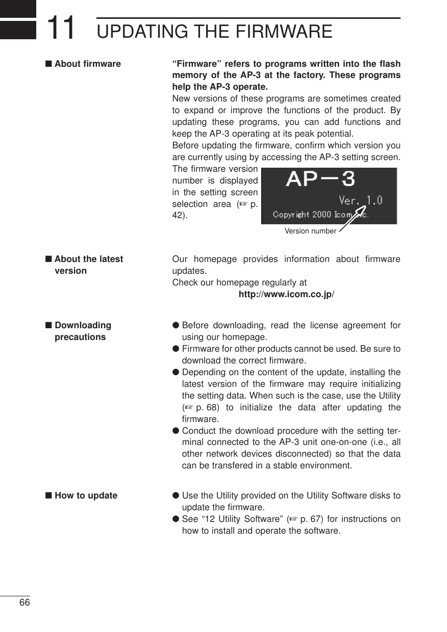
![UTILITY SOFTWARE126812-3 Using the UtilityIn order to communicate with the Utility, the AP-3must be started up in [Update Mode] according to thefollowing procedure:1. Hold down the <MODE> button. Then supply power tothe AP-3 unit or lightly press and release the <RESET>button. • The [LAN] lamp and the lamp will flashin unison.2. Release the <MODE> button when the <POWER>indicator lamp starts flashing.• The <POWER> lamp will continue to flash rapidlywhile operating in [Setting Initialization Mode].[NOTE]When the AP-3 is started upin [Update Mode], the WEPfunction (i.e., wireless LANsecurity level) will becomeineffective automatically. ıConnect the settingterminal (computer)After the AP-3 has been started up in [Update Mode],connect the setting terminal (wired or wireless) con-taining the Utility software to the AP-3 unit one-on-one (i.e., all other network devices disconnected). • The [LAN] lamp will illuminate if the setting terminal hasa wired connection with the AP-3.• The lamp will illuminate if the setting ter-minal has a wireless connection with the AP-3.* IP address conflicts and other network disruptions mayoccur if the setting data is initialized or the firmware isupdated from a terminal connected to an operating net-work.ÇStart up the utility From Windows, click <Start> and select this Utilityfrom the [Program] menu. The [AP-3 Utility] screen isdisplayed.[AP-3 Utility] screenqwertyuÅStart up the AP-3 in[Update Mode]](https://usermanual.wiki/ICOM-orporated/AP-3/User-Guide-130793-Page-76.png)
![UTILITY SOFTWARE 1269ÎOperate the utility The procedures for operating the [AP-3 Utility] screenare explained below. Encircled numbers refer to thereference numbers shown in the screen shot on page68. [EXTREMELY IMPORTANT]Never turn off the power to the AP-3 unit while it isrestarting after initializing the user data (settingdata) or updating the firmware (☞p. 70 and 71). If the power is turned off before the restart processis completed, the data in the AP-3 unit will be lostand the AP-3 will no longer function.After “Processing completed. Restarting system...” isdisplayed in area uof the [AP-3 Utility] screen, waituntil the lamps on the front panel return to the state theywere in before the restart process began. Î-1 Initializing the setting data[Scope of initialization]When the initialization is executed from the Utility, all set-ting data are initialized. [Procedure]1. Enter the IP address of the AP-3 unit in the [AP-3 IPAddress q] text box. (default value: 192.168.0.1)2. Click the radio button next to [Initialize User Data]under [Function w]. 3. Click the <Execute t> button.• The status of the initialization is indicated in the areauat the bottom of the screen. During restart, all frontpanel lamps will be illuminated. When restart is com-pleted, the lamps will return to their original state (i.e.,how they were before the initialization was executed).* The message “AP-3 not found” will be displayed ifcommunication between the setting terminal and theAP-3 unit fails. Check the following:• Is the AP-3 unit in [Update Mode] (☞p. 68)?• Did you enter the correct AP-3 IP address (☞p. 42)into the [AP-3 IP Address q] textbox?4. Close the Utility.](https://usermanual.wiki/ICOM-orporated/AP-3/User-Guide-130793-Page-77.png)
![UTILITY SOFTWARE127012-3 Using the Utility (continued)Î- 2 Updating thefirmware Be sure to read “General Precautions” (☞p. 4) regard-ing updating the firmware. Bear in mind that the resultsof updating the firmware will be on your own responsibil-ity.[Time requirements]The approximate times required for the setting terminal(wired or wireless) to transfer the firmware data file to theAP-3 and for the AP-3 to restart are as follows:• Transfer time= 10 seconds for a wired terminal, 30seconds for a wireless terminal• Restart time = 1 minute (wired or wireless)[Precautions](IMPORTANT)Conduct the firmware transfer using a wired or wirelessterminal (setting terminal) in which the Utility software hasbeen installed. Connect the setting terminal to the AP-3unit one on one (i.e., with all other network devices dis-connected) to prevent the occurrence of errors during thetransfer. Checking the following items regarding the work-ing environment before updating the firmware accordingto the procedure below:◆Regarding a wired setting terminal• Remove the wireless LAN card from the card slot ofthe AP-3 unit.• Connect only the wired setting terminal to the AP-3unit.◆Regarding a wireless setting terminal* If possible, it is recommended that a wired connectionbe used between the setting terminal and the AP-3unit when updating the firmware.• Disconnect the Ethernet cable from the AP-3 unit.• Connect only the wireless setting terminal to the AP-3 unit.• Position the wireless setting terminal within 1 m of theAP-3 unit.[Procedure]1. Enter the IP address of the AP-3 unit in the [AP-3 IPAddress q] text box. (default value: 192.168.0.1)2. Click the radio button next to [Update firmware] under[Function w]. 3. Type the name of the data file (extension: dat) in the[Firmware file name e] text box or click <Browse r>and select the data file from the directory where it wasdownloaded onto the hard disk.·············································Continued on following page](https://usermanual.wiki/ICOM-orporated/AP-3/User-Guide-130793-Page-78.png)
![UTILITY SOFTWARE 12714. Click the <Execute t> button.• The status of the data file transfer is indicated in thearea yu at the bottom of the screen. During restart, all lamps on the front panel will be illu-minated. When restart is completed, the lamps willreturn to their original state (i.e., how they werebefore the file transfer was executed).* The message “AP-3 not found” will be displayed ifcommunication between the setting terminal and theAP-3 unit fails. Check the following:• Is the AP-3 unit in [Update Mode] (☞ p. 68)?• Did you enter the correct AP-3 IP address (☞p. 42)into the [AP-3 IP Address q] textbox?5. Close the Utility.[Transfer failure]The data file transfer may have failed if the [AP-3Utility] screen and AP-3 unit lamps are found to be inany of the states described below.• The bar that indicates the transfer status in the sectionyat the bottom of the Utility screen (☞p. 68) either wasnot displayed at all or ceased to be displayed before thetransfer finished.• While the message “Transferring data...” was displayedat the very bottom of the Utility screen, the [LAN] lampof the AP-3 unit continued to flash without changing.• The message “Data transfer failed...Restart AP-3” wasdisplayed.The above situations indicate that a problemoccurred in the communication with the AP-3. Checkthe items listed below. Then restart the AP-3 andrepeat the transfer.* Regarding a wired setting terminal• Check the condition of the Ethernet cable connectedbetween the setting terminal and the AP-3.• Check if the [LAN] lamp is illuminated.* Regarding a wireless setting terminal• Check the transmission distance between the wirelessterminal and the AP-3 unit.• Check if the lamp is illuminated.](https://usermanual.wiki/ICOM-orporated/AP-3/User-Guide-130793-Page-79.png)
![SETTING SCREEN CONFIGURATION MAP1372The figure below illustrates the configuration of the setting screen.[Wireless LAN Settings] screenWireless LAN Settings MAC Address Security SettingsStatic Routing SettingsNetwork Interface ListRouting Mode SettingsDHCP Server SettingsManager ID Settings SYSLOG SettingsAP-3 IP Address SettingsSL-1100 or SL-1105 Advanced Settings[AP-3 Network Settings] screen[Routing Settings] screen[AP-3 Management Settings] screenRIP SettingsIP Routing Information[Save Settings] screen[Initialize Settings] screen [Setting Initialization Mode] screen(☞P47)(☞P51)(☞P55)(☞P58)(☞P60)(☞P65)(☞P47)(☞P47)(☞P51)(☞P55)(☞P55)(☞P58) (☞P59)(☞P57)(☞P55)(☞P51)(☞P52)(☞P50)Start up in [Setting Initialization Mode](☞P63)Static DHCP Server Settings(☞P54)](https://usermanual.wiki/ICOM-orporated/AP-3/User-Guide-130793-Page-80.png)
![REFERENCE INFORMATION 147314-1 Default Setting Values[Wireless LAN Settings] screenWireless LAN Settings• ESS ID: LG (alphanumeric characters, uppercase)SL-1100 Advanced SettingsSL-1100 Settings• Channel: 11• Security level: NoneMAC Address Security Setting• Use MAC Address Security: No[AP-3 Network Settings] screenRouting Mode Setting• Use Routing Mode: NoAP-3 IP Address SettingsWired LAN• IP Address: 192.168.0.1• Subnet Mask: 255.255.255.0Wireless LAN• IP Address: 192.168.1.1• Subnet Mask: 255.255.255.0DHCP Server Settings• Use DHCP Server Function: Yes• Lease Time: 3 daysWired LAN• Initial Allocation IP Address: 192.168.0.10• Subnet mask: 225.225.225.0• Number of Allocations : 30Wireless LAN• Initial Allocation IP Address: 192.168.1.10• Subnet mask: 225.225.225.0• Number of Allocations: 30[Routing Settings] screenRIP Setting• Use RIP: Yes[AP-3 Management Settings] screenSYSLOG Settings• Use DEBUG: Yes• Use INFO: Yes• Use NOTICE: No• Facility: 114-2 Function List• Wireless access point function• Wireless roaming function• Wireless security(ESS ID, MAC address, WEP)• Routing protocolTCP/IP (RIP static)• DHCP server function• DHCP static function• Supports SYSLOG • Remote setup (web browser)• Firmware Update14-3 [ETHERNET] Port12345678One RJ-45 modular jack (8-pin)1. Send (+)2. Send (–)3. Receive (+)4. Not used5. Not used6. Receive (–)7. Not used8. Not usedThe original factory setting values are listed below for each setting screen of theAP-3 unit.](https://usermanual.wiki/ICOM-orporated/AP-3/User-Guide-130793-Page-81.png)
![REFERENCE INFORMATION147414-4 Basic Setting ExampleThis section presents some of the setting valuesentered when the AP-3 unit is used in the networkconfiguration illustrated below.For setting items not shown here, enter values thatare appropriate for the particular network configura-tion.[DR-1 WL:Required Settings]• Use DHCP server function.• DR-1WL IP address:192.168.0.1InternetWireless terminalWired terminalSL-1100SL-1100AP-3DR-1WL■Using the same subnet for both the wired and wireless LAN[AP-3: Required Settings]• Use DHCP server function.• AP-3 IP address:192.168.0.2• Initial allocation IPaddress: 192.168.0.50• Do not use routingmode.[Setting Tips]Only change the values inthe "Wired LAN" column ofthe [DHCP Server Settings]screen.Set the initial allocation IPaddress so that the range ofIP addresses over which theAP-3 can allocate does notoverlap the range of IPaddresses over which theDR-1WL (router) can allo-cate.Set the [Default Gateway]and the [Primary DNSServer] to the same value asthe IP address of the DR-1WL.Although the [RIP Setting]does not have a direct influ-ence on the performance ofthe network, unnecessarytraffic can be avoided by notusing RIP.[AP-3 Network Settings] screen[Routing Setting] screen* The wired terminal will obtain an IP address from eitherthe DR-1WL or the AP-3.* The wireless terminal will obtain an IP address from theAP-3.](https://usermanual.wiki/ICOM-orporated/AP-3/User-Guide-130793-Page-82.png)
![REFERENCE INFORMATION 147514-5 Practical Setting ExampleThis section presents some of the setting valuesentered when the AP-3 unit is used in the networkconfiguration illustrated below.For setting items not shown here, enter values thatare appropriate for the particular network configura-tion.[DR-1 WL: Required Settings]• Use DHCP server func-tion.• DR-1WL IP address:192.168.0.1• Use RIP on the LANside.• Use substitute responsefunction of DNS server.InternetWireless terminalWired terminalSL-1100SL-1100AP-3DR-1WL■Using the different subnets for the wired LAN and the wireless LAN[AP-3: Required Settings]• Use DHCP server func-tion.• AP-3 IP address:192.168.0.2• Initial allocation IPaddress: 192.168.0.50• Use RIP.• Use routing mode.[Setting Tips]Change the values in boththe "Wired LAN" and"Wireless LAN" columns ofthe [DHCP Server Settings]screen.Set the initial allocation IPaddress so that the range ofIP addresses over which theAP-3 can allocate does notoverlap the range of IPaddresses over which theDR-1WL (router) can allo-cate.Set the [Default Gateway] tothe same value as the IPaddress of the AP-3 unit.Set the [Primary DNSServer] to the same value asthe IP address of the DR-1WL.[AP-3 Network Settings] screen[Routing Setting] screen* The wired terminal will obtain an IP address from eitherthe DR-1WL or the AP-3.* The wireless terminal will obtain an IP address from theAP-3.* The routing information created using RIP is displayedon the [IP Routing Information] screen.](https://usermanual.wiki/ICOM-orporated/AP-3/User-Guide-130793-Page-83.png)
![MAINTENANCE1576■Checking the connection with the AP-3If the IP address of each station (terminal group) isset correctly, you can easily test whether or not IPpackets are reaching their proper destination byusing the “ping” command. To conduct the test, open the MS-DOS window and enterthe following command:ping xxx.xxx.xxx.xxxwhere “xxx.xxx.xxx.xxx” is the IP address of the AP-3 unit. By executing the ping command, four pings (echorequests) are transmitted and a reply message should bereceived for each ping. If a reply is not received, checkthe protocol settings of the station and the AP-3 unit, aswell as the settings of the respective wireless LAN cards(Network Mode, ESS ID, etc.). The message “destination unreachable” will be displayedif the IP address and subnet mask of the station and AP-3 unit are not set correctly.●[Example of ping command execution] (normal case)Windows 98](https://usermanual.wiki/ICOM-orporated/AP-3/User-Guide-130793-Page-84.png)