ICOM orporated AP-3 Access Point User Manual ap 3e qxp
ICOM Incorporated Access Point ap 3e qxp
Manual
INSTRUCTION MANUAL
WIRELESS ACCESS POINT
AP-3
This device complies with Part 15 of the FCC Rules.
Operation is subject to the following two conditions: (1)
this device may not cause harmful interference and (2)
this device must accept any interference received, includ-
ing interference that my cause undesired operation.

Thank you for purchasing an ICOM WAVEMASTER wireless
access point.
This wireless access point is provided with the functions nec-
essary for supporting a wireless LAN.
This manual is designed to help you use your new wireless
access point to its fullest potential. Read this manual careful-
ly before using the wireless access point.
TRADEMARK CREDITS
WAVEMASTER is a registered trademark of ICOM Inc.
Windows is a registered trademark of Microsoft Corporation in the United
States and/or other countries.
The screen shots that appear within this text are used with permission of
Microsoft Corporation.
Macintosh and Mac-OS are registered trademarks of Apple Computer,
Inc., in the United States.
Netscape Navigator is a trademark of Netscape Communications
Corporation.
Other product and company names mentioned herein are the trademarks
or registered trademarks of their respective owners.
INTRODUCTION

SUMMARY OF FEATURES
●All settings can be adjusted using a web browser.
●Networks combining wireless LAN and wired LAN components can be
constructed with ease.
●Includes both wireless access point functions (including roaming) and
wireless bridge functions.
●Supports 11-Mbps wireless access point communications and
100BASE-TX wired LAN communications.
●Supports all ICOM wireless LAN cards (as of May 2000).
●Includes such advanced security functions as ESS ID settings, MAC
address registration, and WEP encryption.
USER REGISTRATION
Be sure to fill out the user registration card and return it to us.
You must return the card to be eligible for technical support and ser-
vice.
INTRODUCTION

INTRODUCTION
WIRELESS LAN CARD
This wireless access point is designed for use with an 11-Mbps wireless
LAN card. When setting the wireless access point to a channel (see p. 47)
other than channel 11, be sure to read “Precautions Regarding Radio
Interference.”
PRECAUTIONS REGARDING RADIO INTERFERENCE
The frequency band used by this wireless access point is also used by
microwave ovens and other industrial, scientific, and medical devices, as
well as the indoor wireless stations (requiring a license) used for identify-
ing the mobile devices utilized on factory production lines and designated
low-power wireless stations (not requiring a license).
1. Before using this access point, make sure no indoor wireless stations for
mobile device identification or designated low-power wireless stations
are being operated nearby.
2. If this access point interferes with the operation of an indoor wireless
stations for mobile device identification, change the operating frequen-
cy of the access point immediately or stop the signal transmission and
contact your dealer or our service department to discuss measures for
preventing signal interference (such as installing a partition).
3. If this access point interferes with the operation of a designated low-
power wireless station or causes any other problems, contact your deal-
er or our service department at the telephone number indicated below.
Service Department, ICOM AMERICA, INC.
INTRODUCTION
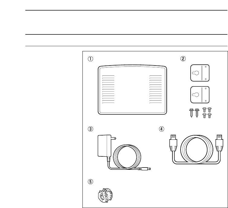
STANDARD PACKING LIST
qAP-3 ·········································································1 unit
wMain unit mounting hardware ··································1 set
eAC adapter (BC-123A)·············································1 piece
rEthernet cable··························································1 piece
* (For connecting to Ethernet port)
tFerrite core (Be sure to install this item. (☞p. 9)····1 piece
●Utility Software disks (for AP-3) ·······························2 disks
●User registration card···············································1 piece
●Instruction manual
●Warranty sheets (for both AP-3 and SL-1100)
★SL-1100 or SL-1105 wireless LAN card is an option

CONTENTS
1. SAFETY PRECAUTIONS —————————————1-5
■FCC precautions····················································5
2. PANEL DESCRIPTION ——————————————6-9
■Front and rear panels ············································6
3. BEFORE CONNECTING CABLES ——————————9
3-1 Attaching the Ferrite Core ··········································9
3-2 Selecting an Installation Site ······································9
3-3 Inserting the Wireless LAN Card ······························10
■Precautions ··························································10
3-4 Mounting the AP-3 Unit·············································11
1. Attach the mounting fittings to the unit·················11
2. Mount the AP-3 unit ·············································11
3-5 Connection Precautions············································13
4. CABLE CONNECTIONS ——————————————14
4-1 Connecting to a Computer········································14
4-2 Connecting to a HUB················································15
4-3 Other Connections····················································16
5. COMPUTER SETTINGS ——————————————17
5-1 Network Settings·······················································17
ÅCheck Ethernet card ············································17
ıCheck protoco······················································17
ÇCheck TCP/IP settings·········································17
Ç-1 Windows 95 and 98 ·····································18
Ç-2 Windows NT 4.0 (WorkStation)····················21
Ç-3 Windows 2000 (Professional) ······················25
Ç-4 MAC OS·······················································32
5-2 Setting Tips ·······························································33
5-3 Checking the Network Settings ································34
■Windows 95 and 98 ·············································34
■Windows NT 4.0 (Work Station) or
Windows 2000 (Professional) ······························35
■Macintosh Operating System·······························36
6. AP-3 SETTINGS —————————————————37
6-1 Before Getting Started··············································37
6-2 Preparing to Adjust the Settings
with a Cable Connection···········································37
ÅConnections ·························································37
ıStarting the AP-3 and computer···························37
6-3 Preparing to Adjust the Settings
with a Wireless Connection ······································38
ÅConnections ·························································38
ıSetting terminal settings·······································38
ı-1 Network Mode··············································38

CONTENTS
ı-2 ESS ID ·························································39
ı-3 Checking the settings···································39
ÇStarting the AP-3 and computer···························41
6-4 Accessing the Setting Screen···································42
6-5 Testing the Operation················································43
7. WIRELESS FUNCTIONS ——————————————45
7-1 Wireless Access Point Function ·······························45
7-2 Roaming Function·····················································46
8. SETTING SCREENS————————————————47
8-1 [Wireless LAN Settings] Screen ·······························47
■Wireless LAN settings··········································47
■SL-1100 or SL-1105 advanced settings···············47
■MAC address security settings ····························50
8-2 [AP-3 Network Settings] Screen·······························51
■Routing mode setting···········································51
■AP-3 IP address settings ·····································51
■DHCP server settings ··········································52
■Static DHCP server settings ································54
8-3 [Routing Settings] Screen·········································55
■RIP setting ···························································55
■IP routing information···········································55
■Static routing settings···········································57
8-4 [AP-3 Management Settings] Screen ·······················58
■Manager ID settings·············································58
■SYSLOG settings·················································59
9. SAVING AND UPLOADING SETTING DATA —————60
9-1 [Save Settings] Screen ·············································60
9-2 Saving Setting Data··················································61
9-3 Uploading Setting Data·············································62
■Precautions regarding editing ······························62
10. SETTING DATA INITIALIZATION ——————————63
ÅUsing the <INIT> button·······································63
ıUsing the setting screen ······································65
11. UPDATING THE FIRMWARE ————————————66
12. UTILITY SOFTWARE ———————————————67
12-1 About the Utility·························································67
12-2 Installing the Utility····················································67
12-3 Using the Utility·························································68
ÅStart up the AP-3 in
[Utility Use Data Update Mode] ··························68
························································Continued on following page

ıConnect the setting terminal (computer)··············68
ÇStart up the utility·················································68
ÎOperate the utility·················································69
Î-1 Initializing the setting data····························69
Î- 2 Updating the firmware ································70
13. SETTING SCREEN CONFIGURATION MAP —————72
14. REFERENCE INFORMATION————————————73
14-1 Default Setting Values ··············································73
14-2 Function List ·····························································73
14-3 [ETHERNET] Port·····················································73
14-4 Basic Setting Example··············································74
14-5 Practical Setting Example·········································75
15. MAINTENANCE ——————————————————76
■Checking the connection with the AP-3···············76
16. AFTER SERVICE —————————————————77
■When the unit fails ···············································77
17. SPECIFICATION —————————————————78
18. GLOSSARY ———————————————————78
CONTENTS

SAFETY PRECAUTIONS 1
1
Be sure to read these precautions in order to use the wire-
less access point safely.
* These precautions are intended to ensure that the access point is operated safe-
ly and correctly. Follow these instructions to avoid property damage and prevent
personal injury to yourself (user) or others in the vicinity.
* Before reading the rest of this manual, read and understand the precautions list-
ed under “RWarning” and “RCaution” below.
* After reading this manual, store it in a convenient place for future review.
■Wireless Access Point
●Do not use any AC adapter other than
the one provided with this product.
Otherwise fire, electric shock, or equip-
ment failure may result.
●Use only the specified parts and
accessories.
Otherwise fire, electric shock, or equip-
ment failure may result.
●Do not connect the power supply to
any terminal other than the DC jack.
Otherwise fire, electric shock, or equip-
ment failure may result.
●Do not modify, excessively bend,
twist, pull, or heat the connecting
cables.
Otherwise the cables may be damaged
and cause a fire, electric shock, or equip-
ment failure.
●Do not place heavy objects on top of
the connecting cables or allow the
cables to be pinched.
Otherwise the cables may be damaged
and cause a fire, electric shock, or equip-
ment failure.
●Install and use in a location where
children cannot reach the power cord
and cables.
Pulled cables could result in electric
shock or personal injury.
●This unit does not require adjustment.
Do not disassemble or modify the unit
or attempt to repair it yourself.
Otherwise fire, electric shock, or equip-
ment failure may result.
●Do not block the ventilation port.
Otherwise fire, electric shock, or equip-
ment failure may result.
●Do not install in a location where the
unit can easily become wet (such as
adjacent to a humidifier).
Otherwise fire, electric shock, or equip-
ment failure may result.
●Do not handle the unit with wet hands.
Otherwise electric shock may result.
●Be sure to ground the unit when
installing. Do not connect the ground-
ing wire to a gas or water line.
Otherwise fire or electric shock may
result.
●Discontinue use immediately and
unplug the power cable from the AC
receptacle if the unit emits smoke, an
abnormal odor, or an abnormal noise
or if water enters the unit.
Otherwise fire, electric shock, or equip-
ment failure may result.
Disconnect the plug of the AC adapter
and all other cables from the unit.
Confirm that the smoke, odor, or noise
stops and contact your dealer or the ser-
vice staff at one of our sales offices.
Failure to observe the precautions listed here could
result in serious or fatal injury to the user or those
near the user.
RRWARNING

SAFETY PRECAUTIONS
1
2
●Do not install the unit outdoors.
Otherwise equipment failure may result.
●Do not place on a slanted or unstable
surface.
Otherwise the unit may tilt over or fall,
resulting in personal injury or equipment
failure.
●Avoid installing in humid, dusty, or
poorly ventilated locations.
Otherwise equipment failure may result.
●Do not use in locations exposed to
direct sunlight, close to heating or
cooling ducts, or otherwise subject to
severe fluctuations in temperature.
Otherwise the unit may become
deformed or discolored. Also, fire or
equipment failure may result.
●Be sure to connect the cables correct-
ly as explained in this manual. Do not
use any other connection arrange-
ment.
Otherwise equipment failure may result.
●Avoid locations exposed to strong
magnetic fields or static electricity and
locations exposed to temperatures or
humidity levels that exceed the speci-
fications listed in the manual.
Otherwise equipment failure may result.
●Do not use close to radios or televi-
sions.
Otherwise signal interference may occur.
●Do not drop or the unit or otherwise
subject it to strong physical shock.
Otherwise personal injury or equipment
failure may result.
●Do not stand, sit, or place heavy
objects on the unit. Do not pinch the
unit.
Otherwise the unit may be damaged.
●When thunder and/or lightning occur
nearby, disconnect the AC adapter
from the wall socket and do not use
the unit. Also, discontinue such work
as connecting cables, disconnecting
cables, installation, or maintenance.
Otherwise fire or electric shock may
result.
●Do not use in locations where conden-
sation is likely to occur. Avoid hastily
moving the unit to a location where
the humidity level is very different
because condensation may occur.
Otherwise the unit may become
deformed or discolored. Also, fire or
equipment failure may result.
If condensation occurs, dry the unit or
allow the unit to remain in the same envi-
ronment until it is completely dry before
using.
●Disconnect the AC adapter from the
unit when the unit will not be used for
a long time.
Otherwise the unit may become hot and
fire or equipment failure may result.
●Do not clean with paint thinner or ben-
zene.
Otherwise the case material may
degrade or the paint may peel. Clean with
a soft cloth. When particularly dirty,
dampen the cloth slightly with a neutral
cleaning agent that has been diluted with
water.
Failure to observe the precautions listed here could
result in personal injury or property damage.
RCAUTION

●Do not touch the LAN card with wet
hands while it is in use.
Otherwise electric shock may result.
●Turn off the power to the wireless
access point before inserting or
removing the LAN card.
Otherwise fire, electric shock, or equip-
ment failure may result.
●Keep the LAN card out of the reach of
children when inserting, removing, or
storing the LAN card.
Otherwise personal injury or electric
shock may result.
●Do not disassemble or modify the LAN
card or attempt to repair it yourself.
Otherwise fire, electric shock, or equip-
ment failure may result.
●Do not allow the LAN card to become
wet.
Otherwise fire, electric shock, or equip-
ment failure may result.
●Do not insert wire or other metal parts
into the connector portion of the LAN
card.
Otherwise fire, electric shock, or equip-
ment failure may result.
Failure to observe the precautions listed here could
result in serious or fatal injury to the user or those
near the user.
RWARNING
●Be sure the correct side of the LAN
card is facing upward when inserting
the card into the PCMCIA slot.
Equipment failure may result if the card is
inserted incorrectly.
●Do not stand, sit, or place heavy
objects on the LAN card. Do not pinch
the LAN card.
Otherwise the LAN card may be dam-
aged.
●Do not drop, apply severe physical
shock to, or twist the LAN card.
Otherwise personal injury may result or
the LAN card may be damaged.
●Do not place the LAN card in humid,
dusty, or poorly ventilated locations.
Otherwise fire, electric shock, or equip-
ment failure may result.
●Do not use near televisions or radios.
The LAN card may disrupt the signal
reception of such devices and such
devices may disrupt the signal reception
of the LAN card.
●Do not remove the LAN card from the
card slot while the wireless access
point is running.
Otherwise equipment failure may result
and data may be lost or damaged.
●Avoid locations exposed to strong
magnetic fields or static electricity and
locations exposed to temperatures or
humidity levels that exceed the speci-
fications listed in the manual. Also, do
not use in locations where condensa-
tion is likely to occur.
Otherwise equipment failure may result.
●Do not use paint thinner or benzene to
clean the LAN card.
Otherwise the case material may
degrade and the paint may peel. Use a
soft cloth to clean the LAN card. If partic-
ularly dirty, dampen the cloth slightly with
a neutral cleaning agent that has been
diluted with water.
Failure to observe the precautions listed here could
result in personal injury or property damage.
RCAUTION
■Wireless LAN card
SAFETY PRECAUTIONS 1
3

General Precautions
●The unit may malfunction if the connecting cables become disconnected or the connection
is unstable while the unit is in operation. Be sure all connectors are securely fastened and
do not touch them while the unit is in operation.
●Observe the instructions provided in the manuals included with the computer and other
peripheral devices.
●This device may cause signal interference when used in a domestic setting. When inter-
ference occurs, move this unit as far as possible away from the affected device.
●The disks entitled “Utility Software” (utility for updating the firmware) is specifically intend-
ed for this unit. Do not use the disks with any other device.
●ICOM Inc. assumes no responsibility whatsoever for any trouble resulting from using the
data files originally provided with this unit or the firmware update data files provided on our
web site in a device other than this unit, or modifying or disassembling this unit. Nor does
ICOM Inc. assume any responsibility whatsoever for any damages or lost profits resulting
from opportunities for voice or signal communications being lost because of the failure,
malfunction, poor condition, damage, or data loss of this unit or because of such external
causes as power failure. ICOM also dismisses all responsibility for demands made by a
third party.
●All copyrights associated with this manual and all intellectual property rights associated
with the hardware and software of this product are held by ICOM Inc.
●Unauthorized reproduction or transmission of this manual, or any part hereof, is prohibited.
●The content of this manual, the hardware and software associated with this product, and
the appearance of this product are all subject to change without notice.
SAFETY PRECAUTIONS
1
4
●Do not use with an AC supply voltage
other than 120V
Otherwise fire, electric shock, or equip-
ment failure may result.
●Do not use with any device other than
the AP-3.
Otherwise fire, electric shock, or equip-
ment failure may result.
●Do not modify, excessively bend,
twist, pull, or heat the AC power cord.
Otherwise the cord may be damaged and
cause a fire, electric shock, or equipment
failure.
●Do not place heavy objects on top of
the AC power cord or allow the cord to
be pinched.
Otherwise the cord may be damaged and
cause a fire, electric shock, or equipment
failure.
●Hold the plug portion when plugging
in and unplugging the AC power cord.
Do not yank the cord.
Otherwise fire, electric shock, or equip-
ment failure may result.
●Do not handle the AC power plug or
other devices with wet hands.
Otherwise electric shock may result.
●Do not use the AC adapter if the AC
power cord is damaged or the plug
does not fit securely into the recepta-
cle.
Otherwise fire, electric shock, equipment
failure, or data loss may result.
Consult with your dealer or the service
staff at one of our sales offices regarding
how to handle the problem or obtain a
new AC adapter.
Failure to observe the precautions listed here could
result in serious or fatal injury to the user or those
near the user.
RWARNING
■AC adapter
1
5
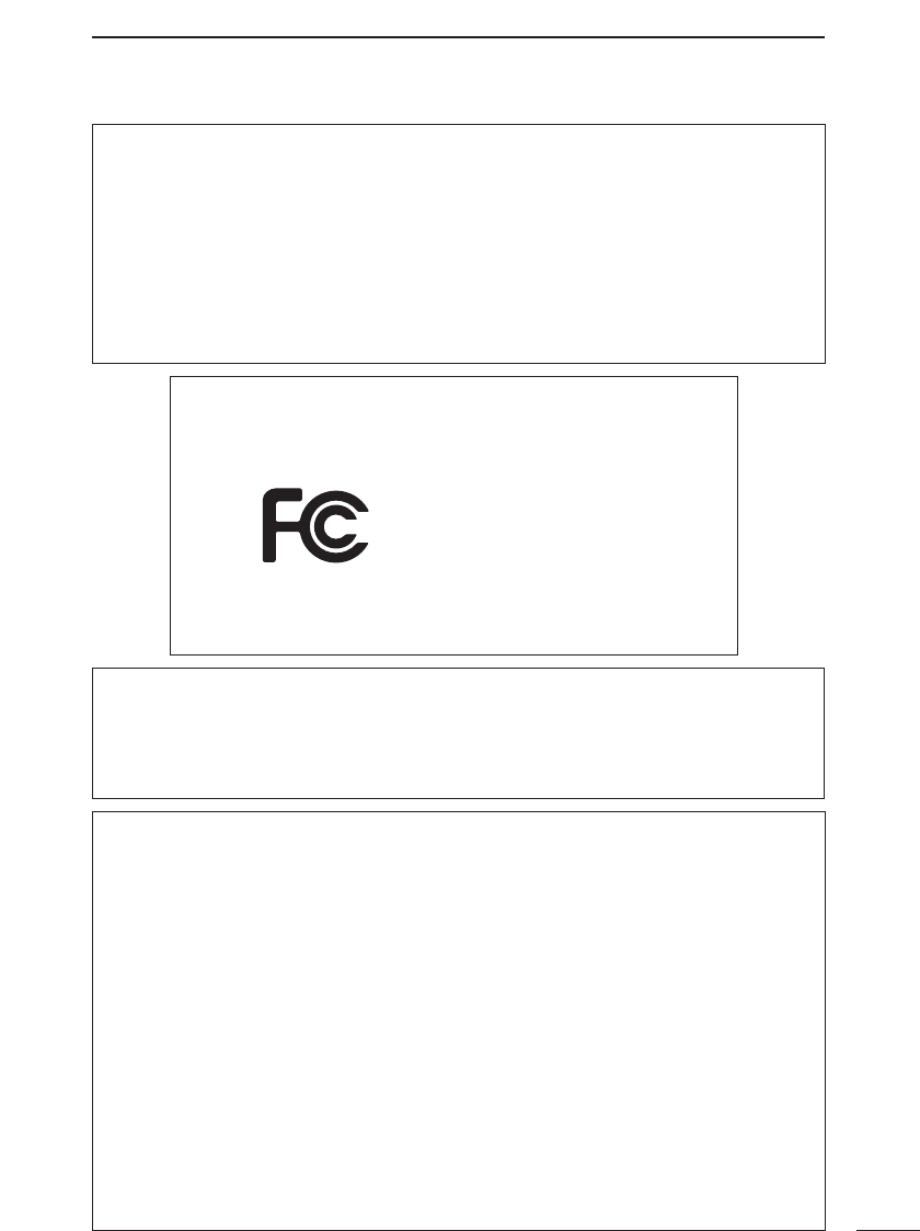
FCC PRECAUTIONS
AP-3
Tested to comply with
FCC standards
FOR HOME OR OFFICE USE
General Precautions
• Be sure to create a backup for the ACCESS POINT utilities disk and use this for normal
operation.
• Refer to the operating instructions accompanying the computer and other peripherals used
in conjunction with the AP-3 regarding the proper operation of those items.
• When installing software or otherwise making changes to the environment of your comput-
er, be sure to create a backup for all critical data stored in your computer. Doing so will hold
the resulting damage to a minimum if something goes wrong.
• Icom will not be held responsible for lost or damaged data under any circumstances.
Note: This equipment has been tested and found to comply with the limits for a Class B
digital device, pursuant to Part 15 of the FCC Rules. These limits are designed to provide
reasonable protection against harmful interference in a residential installation. This
equipment generates, uses, and can radiate radio frequency energy and, if not installed
and used in accordance with the instruction manual, may cause harmful interference to
radio communications. However, there is no guarantee that interference will not occur in
a particular installation. If this equipment does cause harmful interference to radio or tele-
vision reception, which can be determined by turning the equipment off and on, the user
is encouraged to try to correct the interference by one or more of the following measures:
• Reorient or relocate the receiving antenna.
• Increase the separation between the equipment and receiver.
• Connect the equipment into an outlet on a circuit different from that to which the
receiver is connected.
• Consult the dealer or an experienced radio/TV technician for help.
Warning: Changes or modifications not expressly approved by Icom could void the
user’s authority to operate the equipment.
The antenna(s) used for this transmitter must be installed to provide a separation dis-
tance of at least 20 cm from all persons and must not be co-located or operating in con-
junction with any other antenna or transmitter. End-users and installers must be provid-
ed with antenna installation instructions and transmitter operating conditions for satisfy-
ing RF exposure compliance.
PANEL DESCRIPTION
2
6
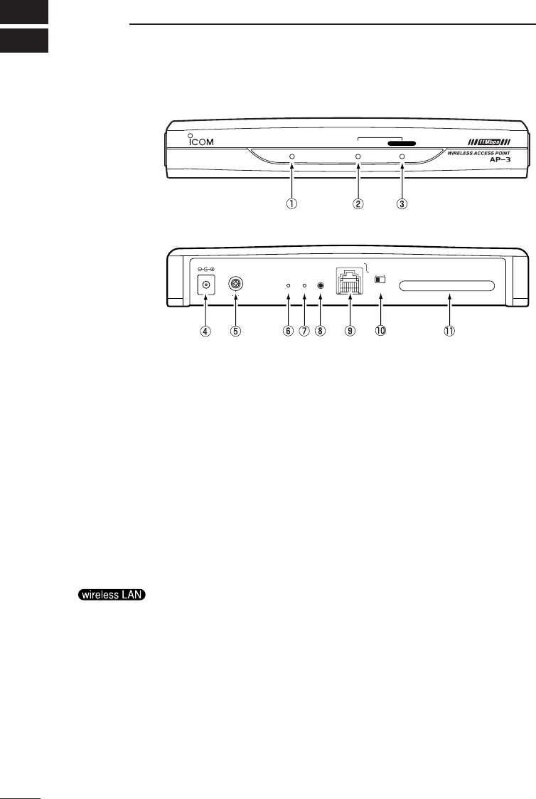
■Front and rear panels
■Front panel
■Rear panel
wireless LAN
LAN
LAN
POWER
DC
WIRELESS LAN CARD
ETHERNET
HUB PC
RESETINIT
MODE
This lamp illuminates when the power to the AP-3 unit is
on.
This lamp flashes slowly when the unit is in [Initialize
mode] (☞p. 63) and rapidly when the unit is in [Update
Mode] (☞p.68).
q[POWER] lamp·········
This lamp illuminates when the wired LAN (Ethernet) con-
nection is normal.
This lamp flashes when the AP-3 unit is communicating
with a wired LAN or wireless LAN.
This lamp goes out if the [ETHERNET] port on the rear
panel can not recognize the LAN connection. In this case,
check the connection of the Ethernet cable and the set-
ting of the [HUB/PC] switch. (☞p. 8, 14, 15)
w[LAN] lamp ···············
This lamp illuminates when the wireless connection to the
AP-3 unit is normal.
This lamp goes out if a wireless communication abnor-
mality occurs. The lamp will also go out if all wireless ter-
minals are inactive for more than one or two minutes or
move out of the wireless communication area for more
than one or two minutes.
If this lamp does not illuminate, check such items as the
IP address of the wireless terminal, the [Network Mode]
and [ESS ID] (☞p. 38) of the wireless LAN card installed
in the wireless terminal, and the [MAC Address Security]
settings (if used).
* This lamp cannot be used to determine whether or not
the LAN card is installed into the PCMCIA slot.
elamp····

PANEL DESCRIPTION 2
7
Connect the AC adapter (BC-123A) to this jack. Be sure
the ferrite core (☞p. 9) is attached to the AC adapter
cord.
rDC jack ·····················
Connect a grounding wire to this terminal.
Use a commercially available grounding wire.
tGround terminal ······
This button is used to put the AP-3 unit into [Utility Use
Data Update Mode], which is the mode used for using the
Utility to update the firmware or initialize the setting data.
* See “12 Utility Software” (☞p. 67) for instructions
regarding how to operate the Utility.
y[MODE] button·········
This button is used to put the AP-3 unit into [Setting
Initialization Mode], which is a mode used for initializing
the setting data to the original factory settings.
* See “10 Setting Data Initialization” (☞p. 63) for instruc-
tions regarding how to use [Setting Initialization Mode]
mode.
u[INIT] button·············
This button is used to restart the AP-3 unit (i.e. initialize
its hardware).
* The result is the same as turning off the power and turn-
ing it back on.
i[RESET] button········
This is an RJ-45 type Ethernet port.
Connect a computer or a hub to the AP-3 unit using the
provided Ethernet cable (straight cable).
* This port can also be used for 100BASE-TX (high-
speed wired LAN) communications.
* Use a Class 5 cable (such as the provided Ethernet
cable) or higher level cable when conducting 100BASE-
TX communications. Avoid lower grade cables.
If a lower grade of cable is used, the grade of the entire
network will be pulled down to the same level.
* If the [LAN] lamp does not illuminate when the power is
on and the AP-3 unit is connected to the wired LAN,
change the setting of the [HUB/PC] switch (☞p. 8).
·············································Continued on following page
o[ETHERNET] port·····

PANEL DESCRIPTION
2
8
■Front and rear panels (continued)
This switch is used to switch the polarity of the [ETHER-
NET] port.
The switch has the following two positions based on dif-
ferences in Ethernet cable type and the hub port being
used.
[PC]: This position sets the [ETHERNET] port to cross-
over mode (symbol: ✕).
Use this setting when an Ethernet cable (straight
cable) is used to connect the AP-3 unit to the
straight port (symbol: =) of a hub or the port (sym-
bol: =) on the Ethernet card side of a computer.
(☞ p. 14)
[HUB]: This position sets the [ETHERNET] port to
straight mode (symbol: =).
Use this setting when an Ethernet cable (straight
connection) is used to connect the AP-3 unit to the
cross-over port (symbol: ✕) of a hub. (☞p. 15)
!0 [HUB/PC] switch······
This is a slot for inserting an ICOM wireless LAN card.
(☞p. 10)
* Turn of the power to the AP-3 unit before inserting or
removing the LAN card.
* This slot is compatible with any ICOM wireless LAN
card. (as of May 2000).
* When the SL-1100 LAN card is used with the AP-3 unit,
use the same model of LAN card with the client as well.
!1 PCMCIA slot·············
BEFORE CONNECTING CABLES 3
9
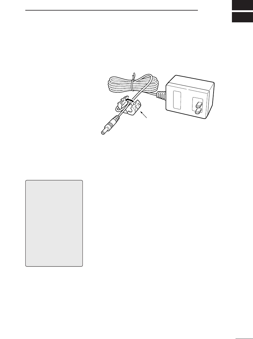
3-1 Attaching the
Ferrite Core
Before using the AC adapter, attach the provided fer-
rite core to the cord in the position shown below.
Otherwise the AC adapter may cause signal interfer-
ence.
3-2 Selecting an
Installation
Site
The installation site for the wireless access point
must be selected carefully in order to avoid signal
interference and reductions in transmission speed
and range.
Observe the following guidelines when selecting the
location.
●Select a location with as clear a line of sight as possi-
ble (i.e., as high as possible).
●Select a stable, level surface that is free of vibrations
and the danger of the unit falling.
●Also observe the following:
• Do not place objects on top of the unit or stack units
on top of one another.
• Radio signals will pass through walls and glass but
not through metal. Concrete walls may be reinforced
with steel or other metal material that will block the
signal.
• The transmission range is widest in an open space.
However, the signal may be reflected from the large
metal walls in such a location as a warehouse.
• Floors generally have steel girders and are installed
with metal fire protection material. Consequently,
communication between different floors is often not
possible.
• Do not install in a location exposed to intense radio
waves (such as near a wireless station) or intense
electromagnetic radiation (such as near a radio trans-
mission tower).
Connect the ferrite core close to
the DC plug. Wrap the cord once
around the ferrite core and close
the ferrite cord until it locks with a
clicking sound.
*Supplied AC adapter may
differ depends on version.
[NOTE]
The transmission range
varies somewhat depending
on the installation location.
Use the line-of-sight dis-
tances indicated below as
guidelines when using an
SL-1100 or SL-1105 wireless
LAN card.
Indoors : approx. 50 m
Outdoors : approx. 150 m
When transmission speed is
11 Mbps
Indoors : approx. 30 m
Outdoors : approx. 70 m
BEFORE CONNECTING CABLES
3
10
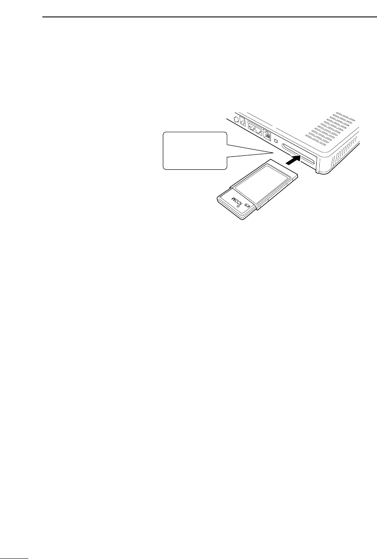
3-3 Inserting the Wireless LAN Card
Turn off the power to AP-3 unit and insert the wireless
LAN card as shown in the figure. To remove the card,
turn off the power and pull the card out.
■Precautions ●Be sure to turn the AP-3 unit off before inserting or
removing the LAN card. Equipment failure may result if
the power is left on.
●There is no need to install special drivers into the AP-3
unit for the wireless LAN card.
●Use only the specified ICOM wireless LAN card.
Otherwise equipment failure may result.
Insert the ICOM
wireless LAN card
into the PCMCIA
slot.
BEFORE CONNECTING CABLES 3
11
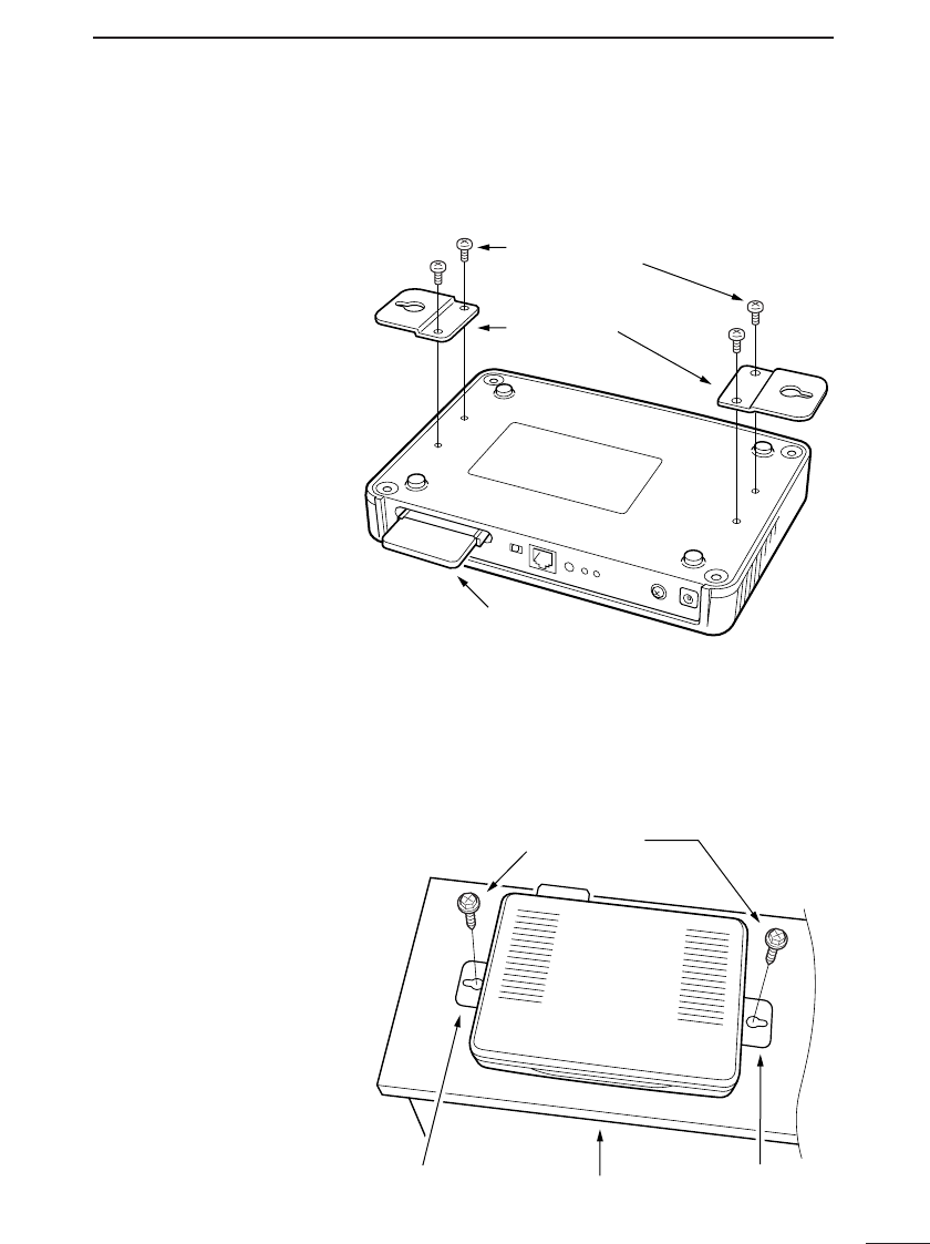
3-4 Mounting the AP-3 Unit
To mount the AP-3 unit to a wall or shelf, refer to the
figure below and use the provided metal fittings.
2. Mount the AP-3 unit. [Mounting to a shelf]
When there is the possibility that people will come into
contact with the cables and power cord, secure the AP-3
with the mounting fittings as shown in the figure to pre-
vent the unit from falling.
1. Attach the mounting
fittings to the unit.
Special machine
screws (4) (included)
Mounting fittings
(included)
Wireless LAN card
AP-3 (bottom)
Tapping screws (2)
(included)
Mounting fitting
(included)
Mounting fitting
(included) Shelf
AP-3 (top)
BEFORE CONNECTING CABLES
3
12
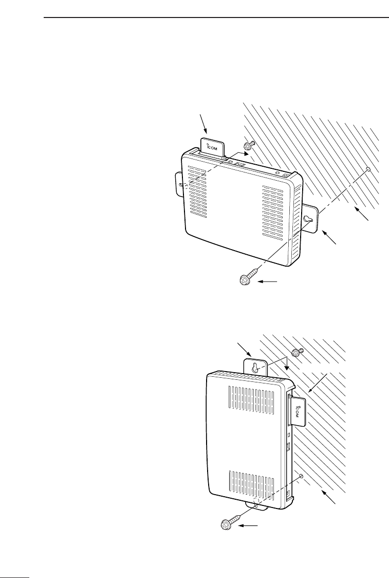
3-4 Mounting the AP-3 Unit (continued)
2. Mount the AP-3 unit. (continued)
[Mounting horizontally to a wall]
[Mounting to vertically to a wall]
Wall
Mounting fittings (2)
(included)
Tapping screws (2)
(included)
Wireless LAN card
AP-3 (top)
Tapping screws (2) (included)
Wall
Mounting fittings (2)
(included)
Wireless LAN card
AP-3 (top)

BEFORE CONNECTING CABLES 3
13
3-5 Connection Precautions
●Use the [ETHERNET] port to connect the AP-3 unit to
the hub or computer.
When connecting the [ETHERNET] port to a computer
using a straight Ethernet cable, set the [HUB/PC]
switch to “PC.” (☞pp. 8 and 16)
●Computers connected to the [ETHERNET] port or the
hub will require an Ethernet card (board).
●Be sure to turn the AP-3 power off before inserting or
removing the LAN card.
●Do not connect the AP-3 to a working network using the
original factory settings.
Also, turn off all computers except the one being used
to change the settings when adjusting the settings
while the AP-3 is connected via a cable or wireless con-
nection to computers in a network.
Otherwise IP address conflicts or other network prob-
lems may occur.
●ICOM wireless LAN cards do not support Macintosh.
●This unit cannot communicate with any wireless LAN
card other than the specified ICOM wireless LAN card.
●Hold the connector when connecting and disconnecting
the Ethernet cable.
CABLE CONNECTIONS
4
14
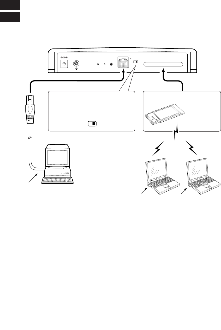
4-1 Connecting to a Computer
* The following models of ICOM wireless LAN card can be used: SL1100 or SL-1105.
*1. The provided Ethernet cable is a straight-through cable.
*2. Turn the power off before changing the position of the [HUB/PC] switch.
Set the switch to “HUB” when using a cross-over cable to connect to the
Ethernet card of a computer.
*3. ICOM wireless LAN cards do not support Macintosh.
Wireless LAN card Wireless LAN card
DC
WIRELESS LAN CARD
ETHERNET
HUBPC
RESETINIT
MODE
HUB/PC
Computer
See “3-3 Inserting
the Wireless LAN
Card” (☞ p. 10)
regarding how to
insert the LAN
card.
Insert into the card slot.
Ethernet cable
(included)
*2
*3
*1
<Wireless LAN card settings>
When connecting the AP-3 to the Ethernet
card of a computer using the provided
Ethernet cable (straight cable), set the
[HUB/PC] switch to “PC” as shown below.
• Set the ESS ID of the wireless
LAN card inserted into the AP-3
to the same value as the ESS ID
of the wireless LAN card inserted
into the computer. (☞ p. 47)
• Check the [Network Mode] setting
of the card inserted into the
computer. (☞ p. 38)
Make sure the [ESS ID] setting is
the same as that of the card
inserted into the AP-3. (☞ p. 39)
CABLE CONNECTIONS 4
15
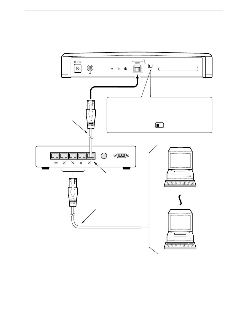
4-2 Connecting to a HUB
*1. The provided Ethernet cable is a straight-through cable.
*2. Turn the power off before changing the position of the [HUB/PC] switch.
Set the switch to “PC” when using a cross-over cable to connect to the cross-
over port of a hub.
*3. Use straight Ethernet cable to connect computers to the cross-over port of the
hub.
DC
WIRELESS LAN CARD
ETHERNET
HUB PC
RESETINIT
MODE
HUB/PC
Computer
Computer
HUB
Ethernet cable
(straight cable)
*2
*3
Ethernet cables
(included)
*1
Cross-over port of hub
When connecting the AP-3 to the cross-over port of a
hub using the provided Ethernet cable (straight cable),
set the [HUB/PC] switch to “HUB” as shown below.
CABLE CONNECTIONS
4
16
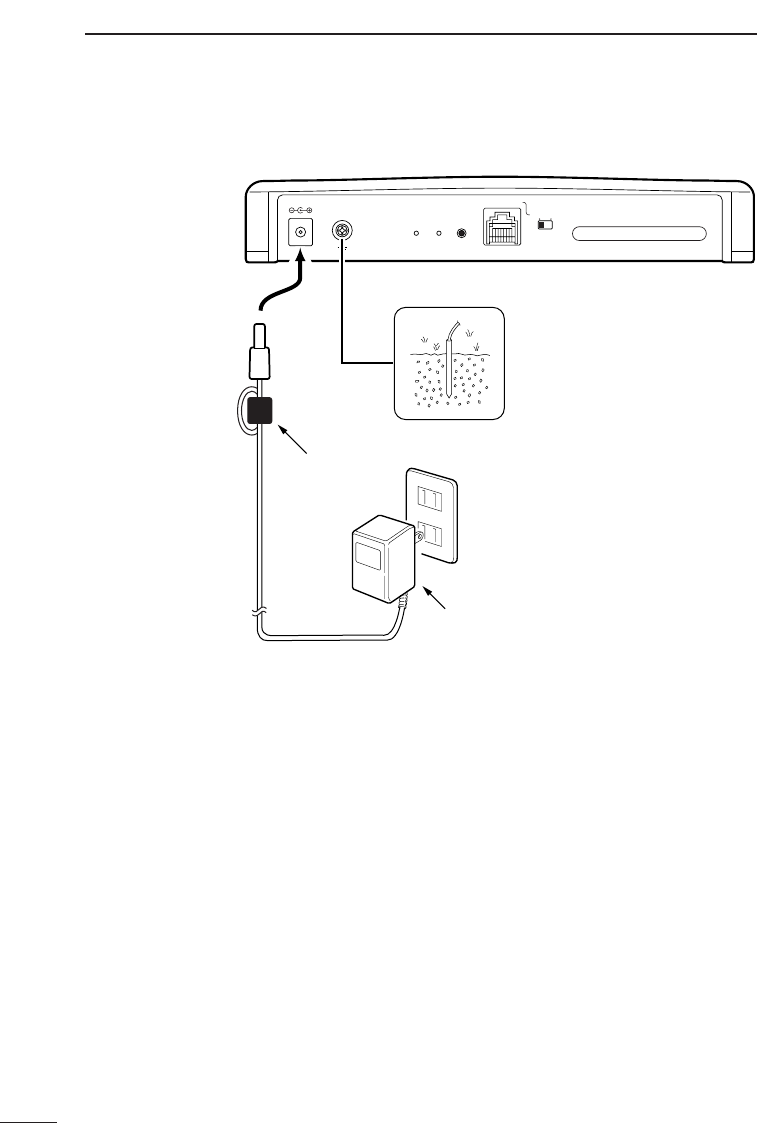
4-3 Other Connections
*1 Use a commercially available ground wire to connect to the grounding terminal.
*2 Be sure to attach the ferrite core (☞p. 9) to the cord before connecting the AC
adapter.
DC
WIRELESS LAN CARD
ETHERNET
HUB PC
RESETINIT
MODE
Ferrite core
(included)
Ground
BC-123A AC adapter
(included)
AC outlet
*1
*2

COMPUTER SETTINGS 5
17
5-1 Network Settings
When adjusting the settings of the AP-3 unit (☞p. 37),
it is better to connect the computer to the AP-3 unit
with a cable. This chapter is written under the
assumption of a cable connection between the com-
puter and the AP-3 unit.
Before connecting the computer to the AP-3 unit,
adjust the protocol (TCP/IP) settings of the computer.
• Proceed to Chapter 6 (☞p. 37) for instructions regard-
ing how to connect a computer that is already being
used in the LAN and use it to adjust the settings of the
AP-3. In such a case, delete all the currently allocated
IP addresses and the default gateway.
• When using a computer that has never been used in a
LAN environment, check the items listed below.
ÅCheck Ethernet card Make sure the computer to be used is installed with an
Ethernet card (Ethernet board) and the provided AP-3 dri-
ver is installed on the Ethernet card.
See the instruction manual provided with the Ethernet
card regarding how to install the driver (if necessary).
ıCheck protocol Make sure TCP/IP is installed in all of the computers.
If installation is required, refer to the Help screen of the
operating system or the instruction manual provided with
the Ethernet card.
ÇCheck TCP/IP
settings
Windows 95 and 98, Windows NT 4.0, Windows 2000,
and Open Transport of the Mac OS all support DHCP
client.
* If the computer does not support DHCP client, set the
following four items manually.
• Local IP address • Subnet mask
• Gateway address • DNS server address
[About wireless LAN settings]
See the instruction manual provided with the ICOM wireless LAN card for instructions regarding how to set
the protocol (TCP/IP) settings of the computer (Windows) into which the wireless LAN card will be insert-
ed and used for the wireless connection with the AP-3.
COMPUTER SETTINGS
5
18
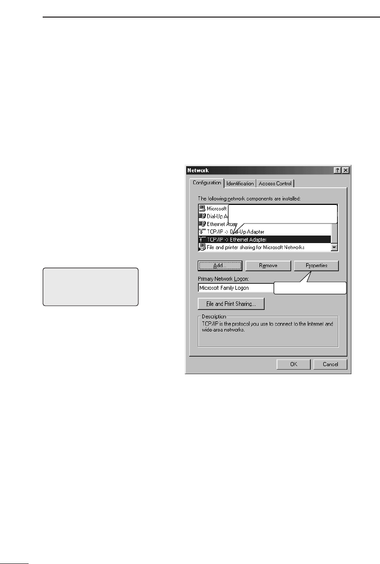
5-1 Network Settings (continued)
Ç-1 Windows 95
and 98
When using Windows 95 or 98, adjust the TCP/IP set-
tings according to the following procedure:
1. Start up the computer.
2. Click <Start> and select [Control Panel] from the
[Settings] menu. Then click the [Network] icon. The
screen shown below is displayed.
• Follow the instructions (1 and 2) indicated on the
screen shot below.
You will make the follow-
ing settings during the
procedure to the right:
• IP Address
Setting: “Obtain an IP
address automatically”
• WINS Configuration
Setting: “Disable WINS
Resolution”
• Gateway
Setting: leave blank
• DNS Configuration
Setting: “Disable DNS”
[NOTE]
When the network settings
are changed, the previous
setting values will be erased.
wClick <Properties>.
qClick the TCP/IP icon for the
Ethernet card (☞ *1)
*1. If there are multiple TCP/IP icons q, select the one
with the corresponding adapter name.
If only one adapter is installed, simply click “TCP/IP.”
*2. If a TCP/IP icon is not included in the list of installed
components, refer to the Help screen of the operating
system or the instruction manual provided with the
Ethernet card for instructions regarding how to install
the TCP/IP protocol.
COMPUTER SETTINGS 5
19
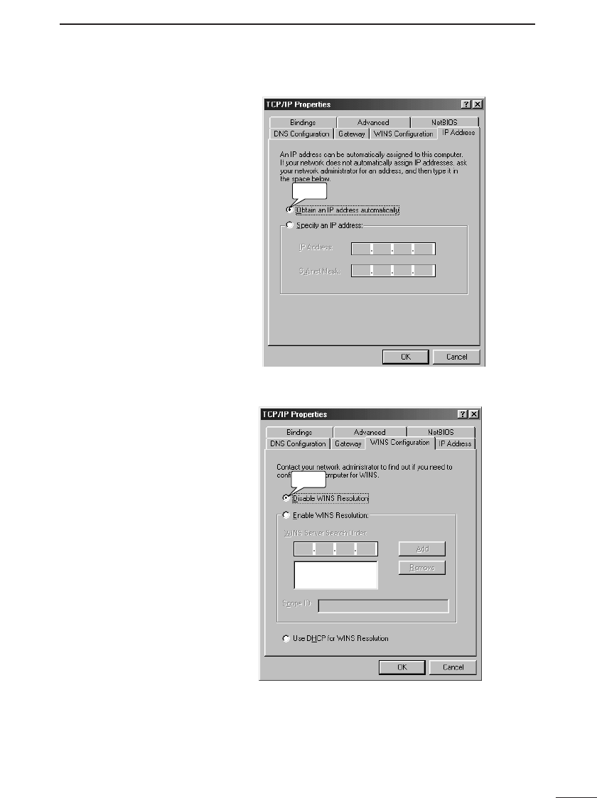
3. Select “Obtain an IP address automatically.”
Click
4. Click the [WINS Configuration] tab and select “Disable
WINS Resolution.”
Click
COMPUTER SETTINGS
5
20
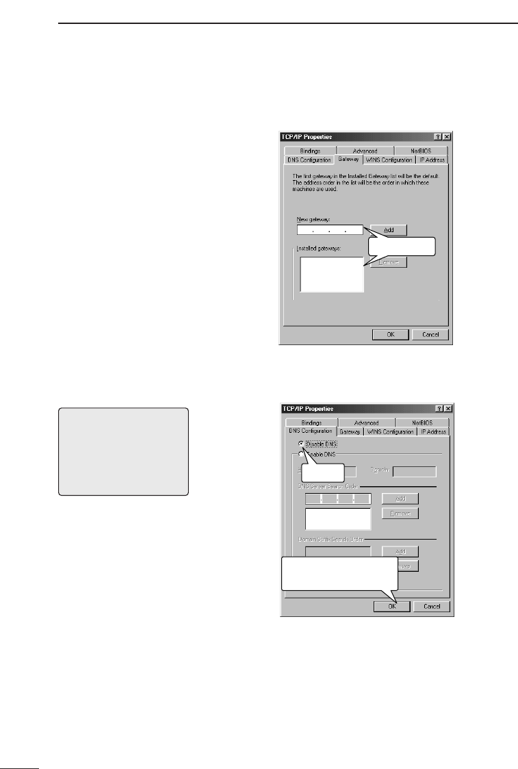
5. Click the [Gateway] tab and make sure there are no
installed gateways.
Leave blank
6. Click the [DNS Configuration] tab and select “Disable
DNS.” Then click <OK>.
Click to close TCP/IP
properties screen.
Click
Ç-1 Windows 95 and 98 (continued)
[NOTE]
When the IP address of the
LAN computer was set man-
ually (i.e., not using DHCP),
enter the IP address of the
AP-3 unit as the address of
the DNS server.
7. Click <OK> on the [Network] screen (☞Step 2, p. 18).
8. A message offering to restart the computer is dis-
played. Select <No> because you will shut down the
computer instead.
9. Click <Start> and select [Shut Down]. Then select
“Shut down” and click <OK>.
10. After the computer shuts down, proceed to Chapter 6
(☞p. 37).
COMPUTER SETTINGS 5
21
5-1 Network Settings (continued)
Ç-2 Windows NT 4.0
(WorkStation)
You will set the following
items during the proce-
dure to the right:
• IP Address
• DNS
• WINS Address
• Routing
[NOTE]
When the network settings
are changed, the previous
setting values will be erased.
When using Windows NT 4.0, adjust the TCP/IP set-
tings according to the following procedure:
1. Start up the computer.
• The Windows NT 4.0 [Log on] screen is displayed.
2. Log on as an Administrator.
3. Click <Start> and select [Control Panel] from the
[Settings] menu. Then click the [Network] icon. The
screen shown below is displayed.
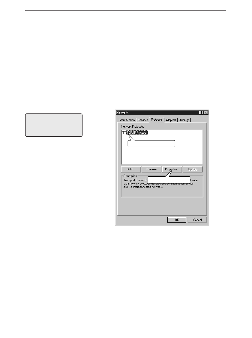
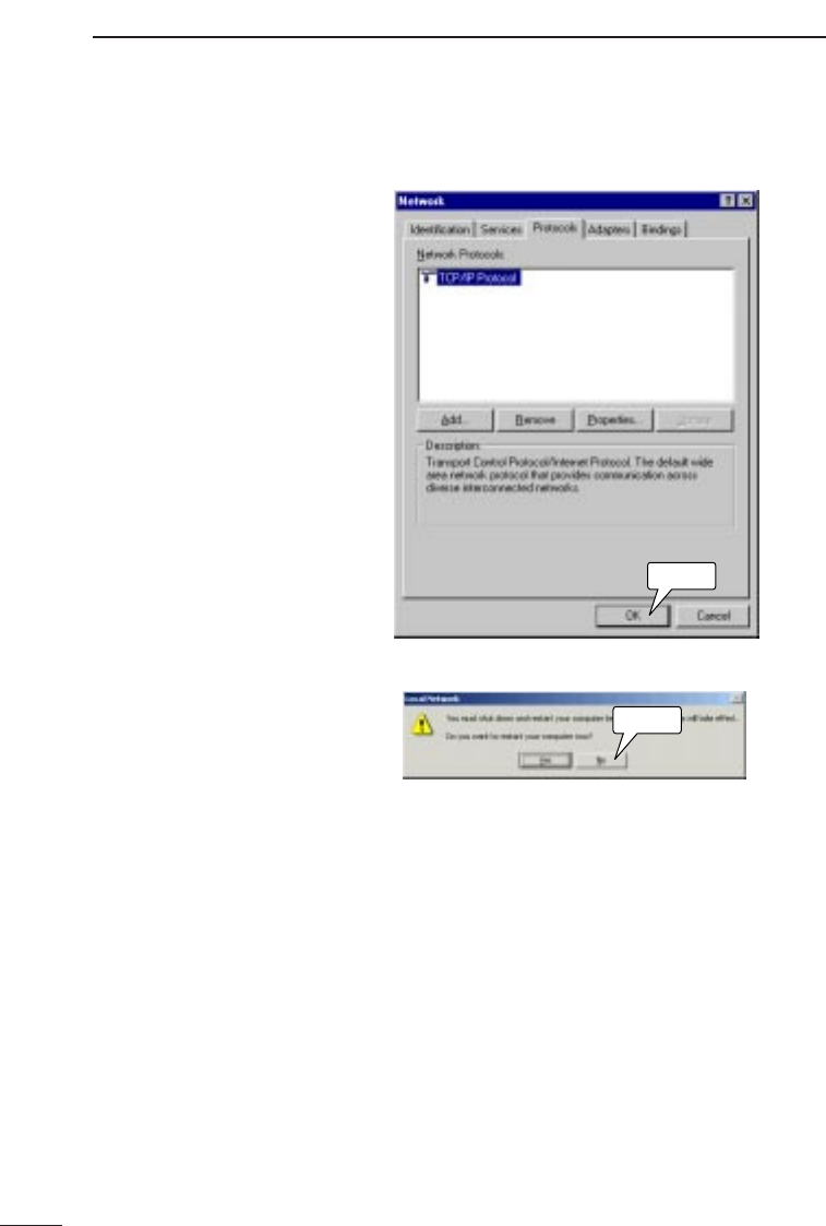
4. Follow the instructions (1 and 2) indicated on the
screen shot below.
qClick the TCP/IP icon.
wClick <Properties>.
* If a TCP/IP icon is not included in the list of network pro-
tocols, refer to the Help screen of the operating system
or the instruction manual provided with the Ethernet
card for instructions regarding how to install the TCP/IP
protocol.
COMPUTER SETTINGS
5
22
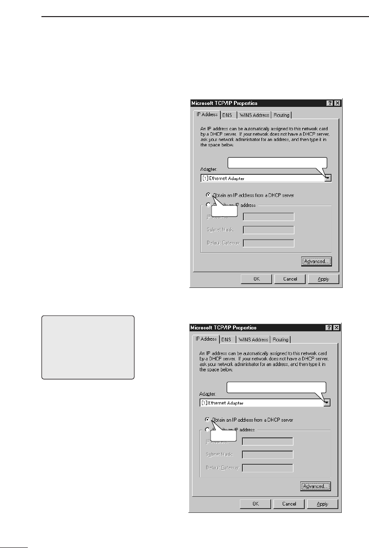
5. Follow the instructions indicated on the screen shot
below.
Select the correct Ethernet card.
Click
6. Click the [DNS] tab and follow the instructions indicat-
ed on the screen shot below.
Select the correct Ethernet card.
Click
Ç-2 Windows NT 4.0 (WorkStation) (continued)
[NOTE]
When the IP address of the
LAN computer was set man-
ually (i.e., not using DHCP),
enter the IP address of the
AP-3 unit as the address of
the DNS server.
COMPUTER SETTINGS 5
23
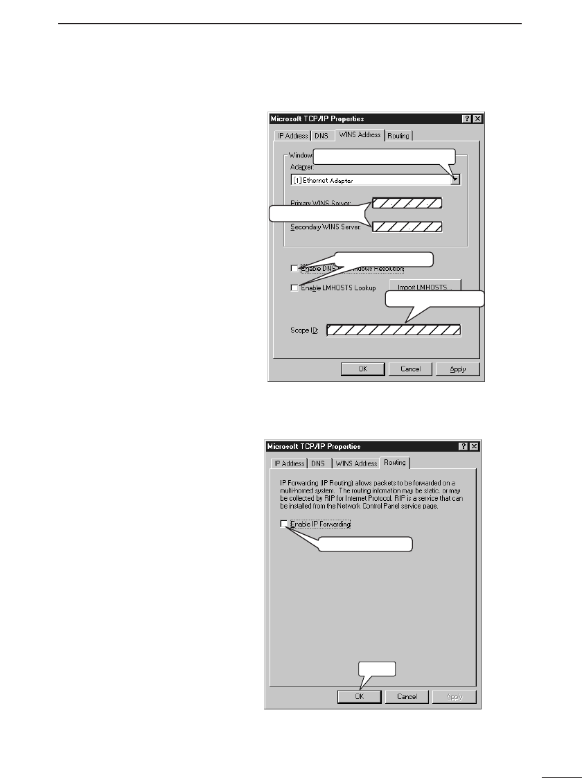
7. Click the [WINS Address] tab and follow the instruc-
tions indicated on the screen shot below.
Do not enter anything.
Do not enter anything.
Select the correct Ethernet card.
Remove check marks.
8. Click the [Routing] tab and follow the instructions indi-
cated on the screen shot below.
Remove check mark.
Click
COMPUTER SETTINGS
5
24
9. Click <OK>.
Click
10. Click <No>.
Click
Ç-2 Windows NT 4.0 (WorkStation) (continued)
11. Click <Start> and select [Shut Down]. Then select
“Shut down” and click <OK>.
12. After the computer shuts down, proceed to Chapter 6
(☞p. 37).
COMPUTER SETTINGS 5
25
Ç-3 Windows 2000
(Professional)
When using Windows 2000, adjust the TCP/IP set-
tings according to the following procedure:
1. Start up the computer.
• The Windows 2000[Log on] screen is displayed.
2. Log on as an Administrator.
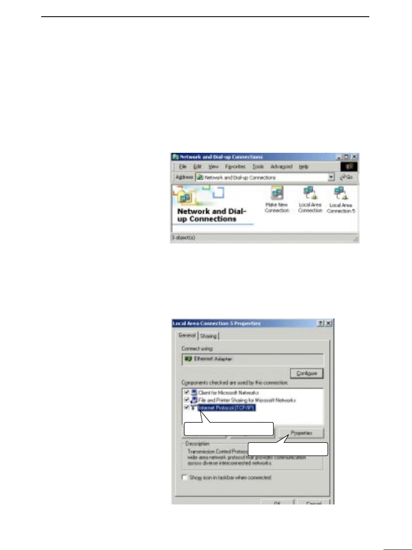
3. Click <Start> and select [Dial-Up Networking] from the
[Settings] menu. The screen shown below is displayed.
q
w
Click the TCP/IP icon.
Click <Properties>.
5-1 Network Settings (continued)
4. Right-click the [Local Area Connection] icon and select
[Properties]. The screen shown below is displayed.
• Follow the instructions indicated on the screen shot
below.
COMPUTER SETTINGS
5
26
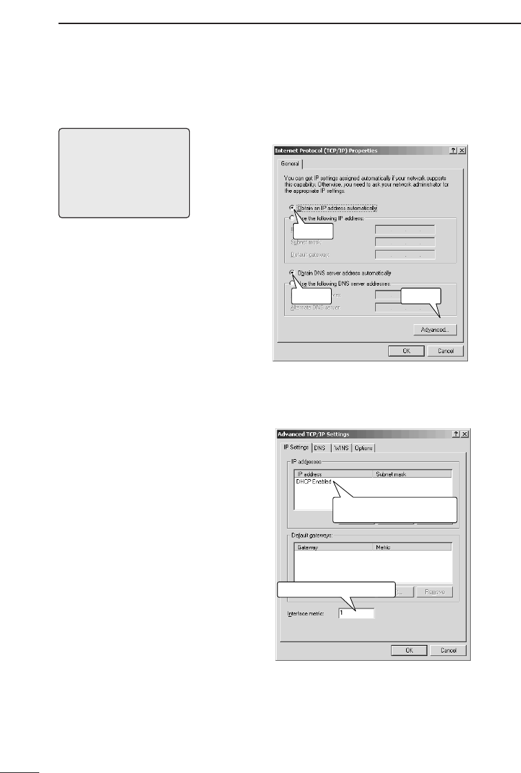
5. Follow the instructions indicated on the screen shot
below.
q
we
Click
Click Click
6. Follow the instructions indicated on the screen shot
below.
Make sure “DHCP enabled”
is displayed.
Make sure "1" is displayed.
Ç-3 Windows 2000 (Professional) (continued)
[NOTE]
When the IP address of the
LAN computer was set man-
ually (i.e., not using DHCP),
enter the IP address of the
AP-3 unit as the address of
the DNS server.
COMPUTER SETTINGS 5
27
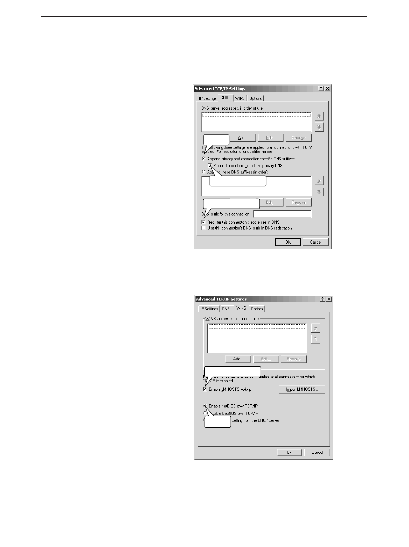
7. Click the [DNS] tab and follow the instructions indicat-
ed on the screen shot below.
Add check mark.
Add check mark.
Click
8. Click the [WINS] tab and follow the instructions indicat-
ed on the screen shot below.
Add check mark.
Click
COMPUTER SETTINGS
5
28
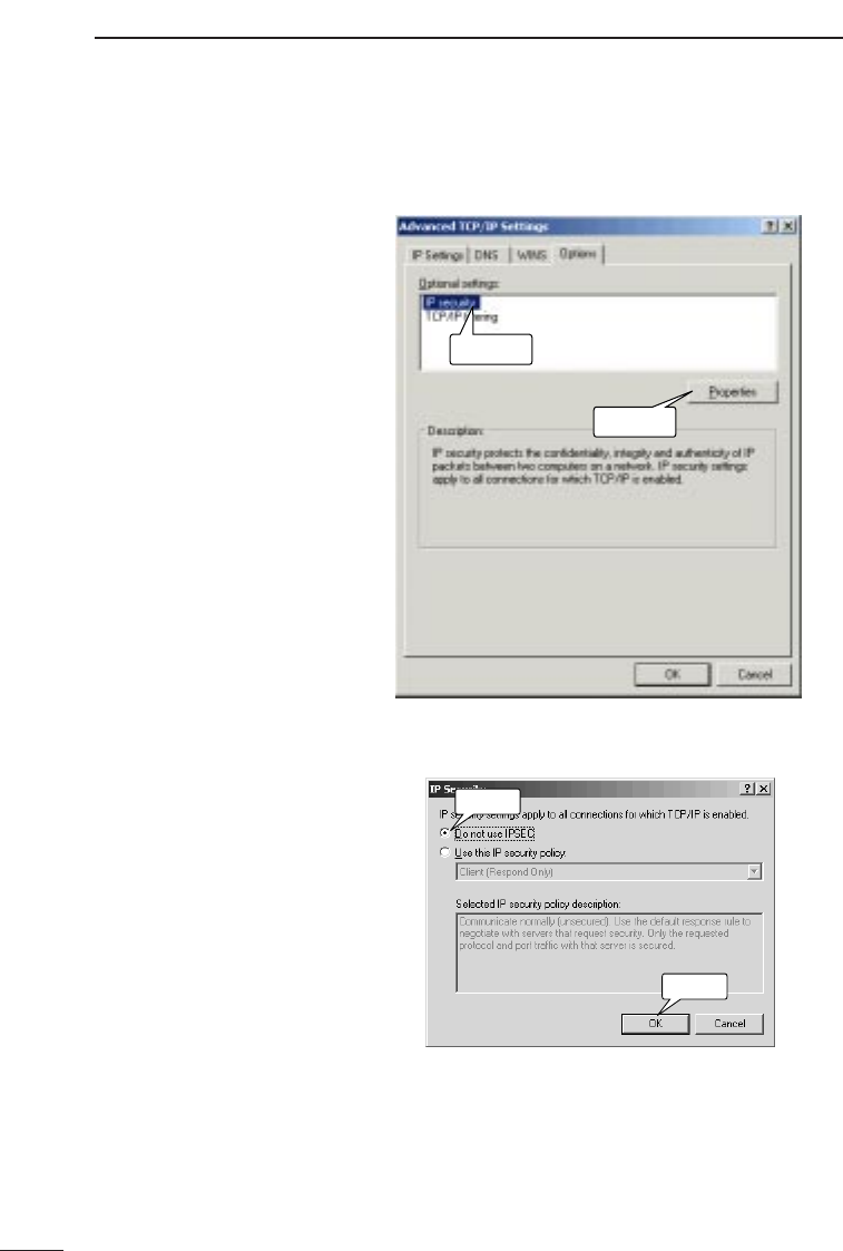
9. Click the [Options] tab and follow the instructions indi-
cated on the screen shot below.
q
w
Click
Click
10. Follow the instructions indicated on the screen shot
below.
q
w
Click
Click
Ç-3 Windows 2000 (Professional) (continued)
COMPUTER SETTINGS 5
29
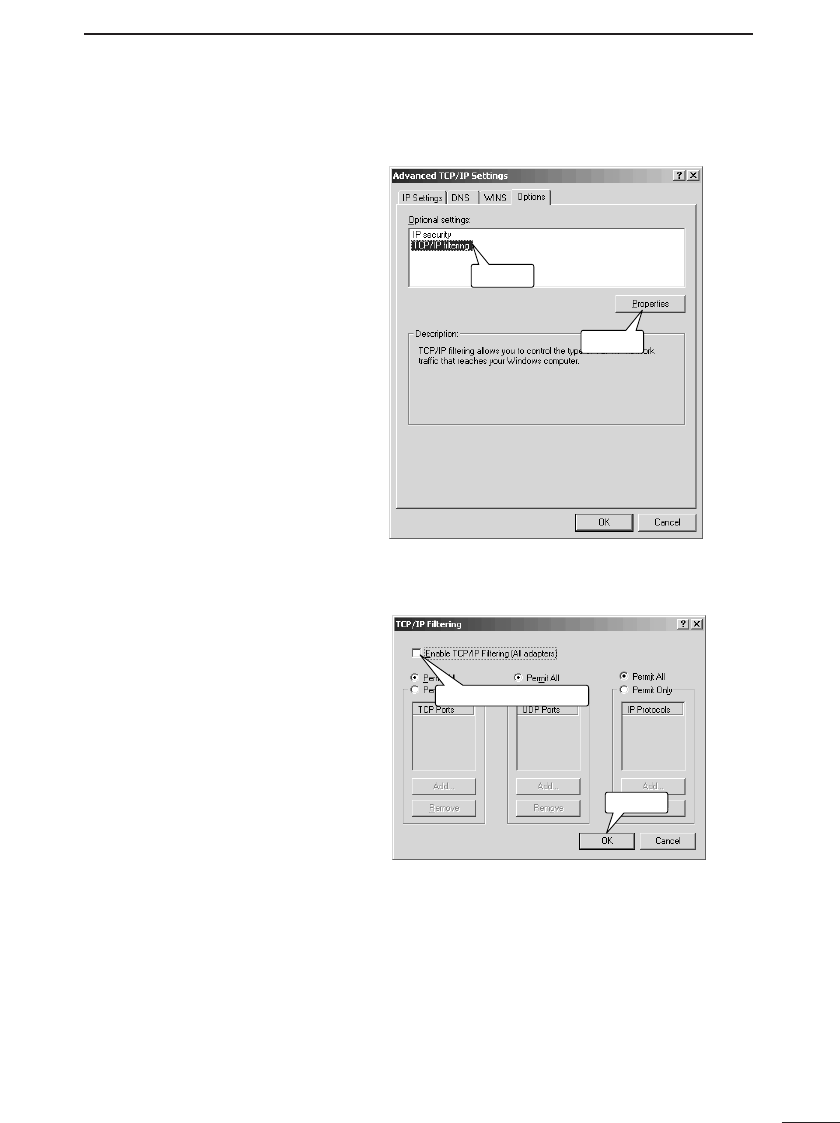
11. Follow the instructions indicated on the screen shot
below.
q
w
Click
Click
12. Follow the instructions indicated on the screen shot
below.
q
w
Remove check mark.
Click
COMPUTER SETTINGS
5
30
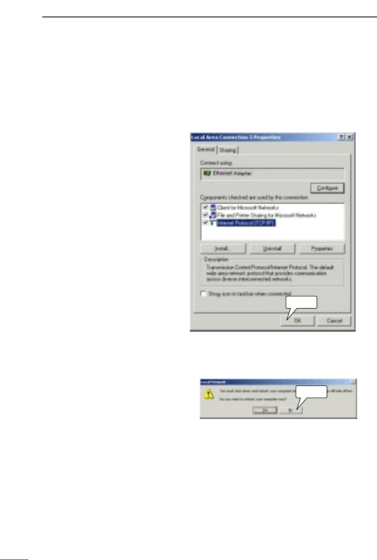
13. Click <OK> on the [Advanced TCP/IP Settings]
screen (Step 11). The screen shown below is dis-
played.
• Follow the instructions indicated on the screen shot
below.
Click
14. A message offering to restart the computer is dis-
played. Click <No>.
Click
Ç-3 Windows 2000 (Professional) (continued)
* Select <No> because you will shut the computer
down instead.
COMPUTER SETTINGS 5
31
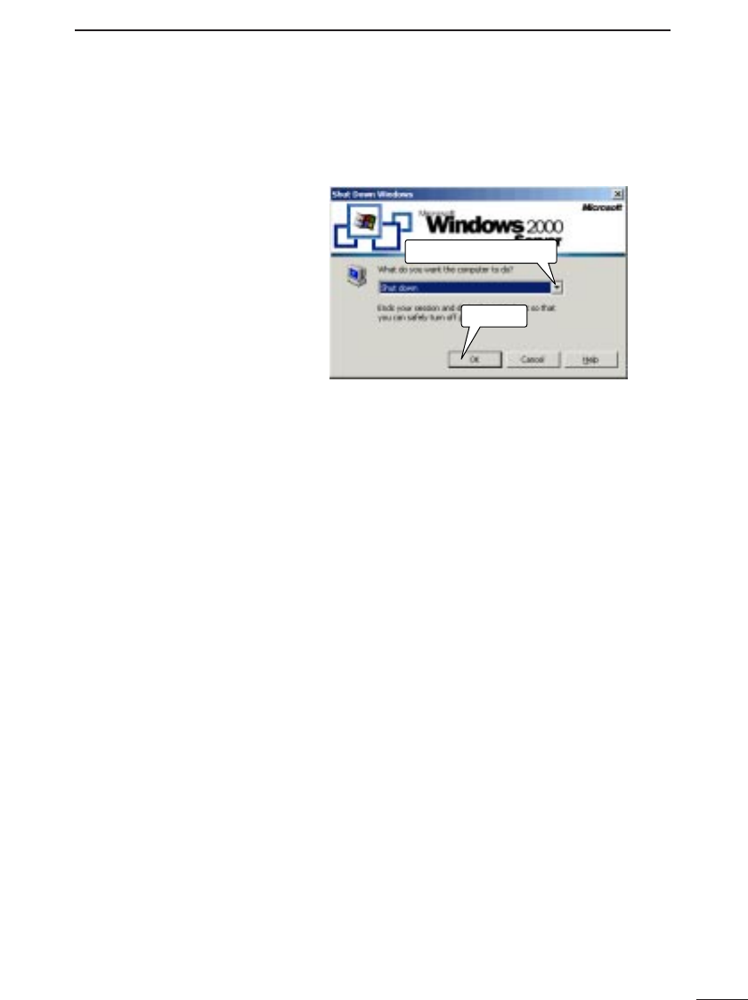
15. Click <Start> and select [Shut Down]. The following
screen is displayed.
• Follow the instructions indicated on the screen shot
below.
w
q
Click
Select “Shut down.”
16. After shutting down the computer, proceed to Chapter
6 (☞p. 37).
COMPUTER SETTINGS
5
32
Ç-4 Macintosh Operating
System
When using a Macintosh operating system, adjust the
TCP/IP settings according to the procedure below.
Since ICOM wireless LAN cards cannot be used with
Macintosh computers, the settings explained here
are to prepare for a cable connection with the AP-3
unit.
1. Start up the computer.
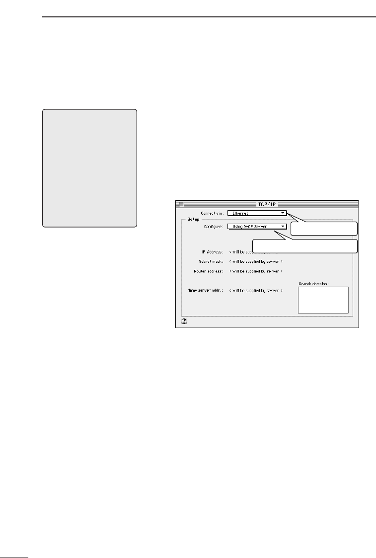
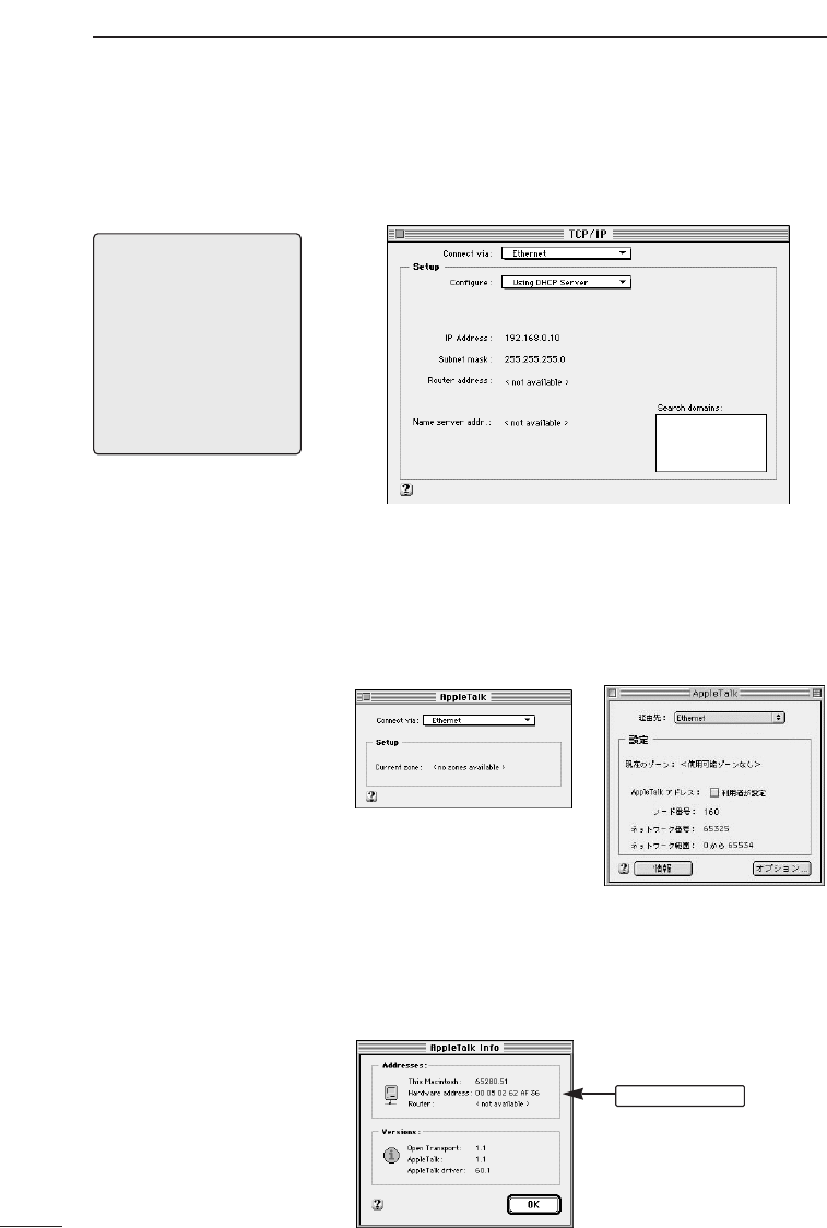
2. Open the [Apple Menu] and select [Control Panel].
Then open the [TCP/IP] screen.
• Follow the instructions indicated on the screen shot
below.
Select “Ethernet.”
Select “Using DHCP server.”
5-1 Network Settings (continued)
[NOTE]
* When the network settings
are changed, the previous
setting values will be
erased.
* This procedure is based on
Mac OS J1-8.6. The order
of the steps and the
screens themselves may
vary if a different version is
used. Consult the Help files
of your Macintosh operat-
ing system for assistance.
* If a TCP/IP item is not included on the [Control
Panel], refer to the Help screen of the operating sys-
tem or the instruction manual provided with the
Ethernet card for instructions regarding how to install
the TCP/IP protocol.
3. Click the close-box button on the title bar.
• The settings are saved and the [TCP/IP] screen
closes.
4. After the computer shuts down, proceed to Chapter 6
(☞p. 37).

COMPUTER SETTINGS 5
33
5-2 Setting Tips ●Complete the settings described in this chapter and
shut down the computer before proceeding to Chapter
6 (☞p. 37).
●Complete the settings described in Chapter 6 (☞p. 37)
before connecting the AP-3 to a working LAN.
●When constructing a TCP/IP network, it is necessary to
set the IP addresses of the computers that will be con-
nected to the network. (☞p. 17).
●A computer running Windows will acquire the local IP
address from the AP-3 when Windows is started up
and a computer using a Macintosh operating system
will acquire the local IP address each time network
communications are begun (e.g., when the computer
accesses the internet or email).
Make sure the AP-3 unit is turned on and “Use DHCP
server function” is set to “Yes” on the screen shown on
page 52.
●When the AP-3 unit attempts to allocate a local IP
address to a computer and another computer (non-
DHCP client for which local IP address was set manu-
ally) is already using the same local IP address, the
AP-3 unit will not detect the existence of the address
used by the other computer.
●When [Routing Mode] (☞p. 51) is not used, the total
number of IP addresses that the AP-3 unit can allocate
automatically to both wireless and wired LAN comput-
ers is a 5 to 128. When [Routing Mode] is used, the AP-
3 unit can allocate 5 to 128 IP addresses to wireless
LAN computers and the same number to wired LAN
computers. The original factory setting for the number
of allocations is 30 for both wired and wireless LAN.
(☞p. 53)
Avoid overlapping between the IP addresses of clients
(including clients having a wireless connection) con-
nected to the same network and the range of IP
addresses that the AP-3 unit can automatically allocate
to computers.
COMPUTER SETTINGS
5
34
5-3 Checking the Network Settings
Use one of the following procedures (depending on
the operating system) to check, release, or reaac-
quire IP address settings that were obtained auto-
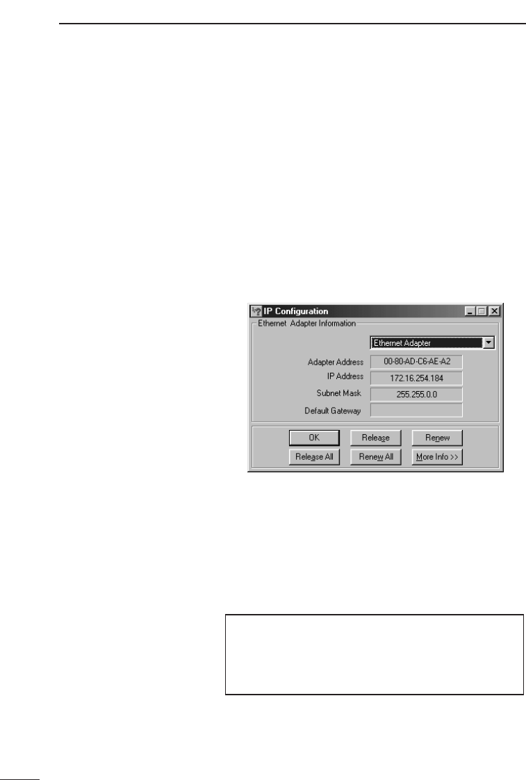
matically. ■Windows 95 and 98
For Windows 95 and 98, use the winipcfg.exe file in the
Windows folder.
[Steps]
1. Click <Start> and select [Run].
2. Type “winipcfg” into the text box and press the [Enter]
key.
• The following screen will appear when the application
starts up:
3. Click the ▼button on the right side of the text box and
select the name of the Ethernet card being used.
Check or release the setting values, or reacquire the
settings.
●Adapter address : MAC address of Ethernet card
COMPUTER SETTINGS 5
35
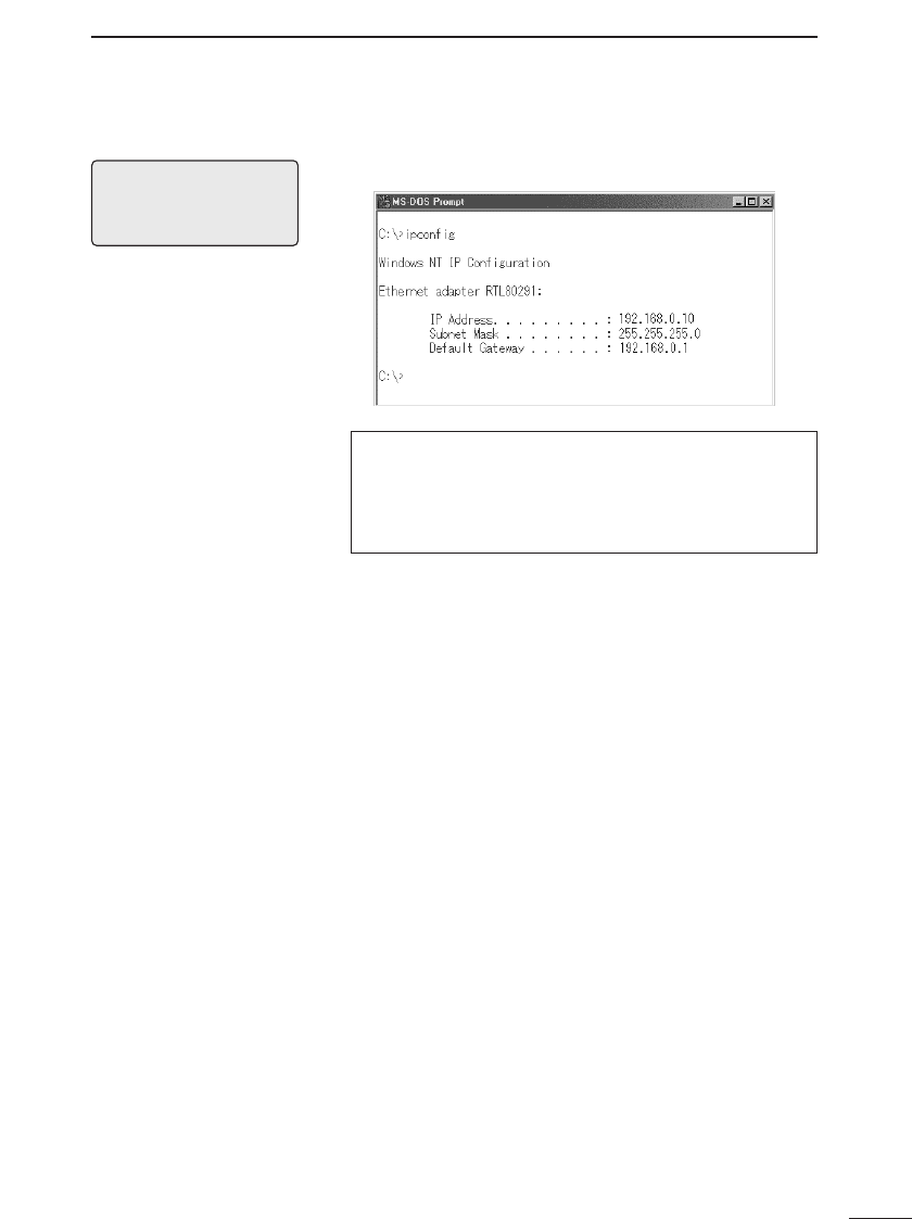
■Windows NT 4.0 (Work Station) or Windows 2000 (Professional)
Run [ipconfig] from the command prompt screen.
[NOTE]
For more information, run
[ipconfig/?] and read the help
information displayed.
Windows NT 4.0 or Windows 2000 will prepare an IP address and
display the [Command Prompt] screen when the IP address has
continuously failed to be obtained from the DHCP server for a cer-
tain amount of time. When this occurs, the computer does not have
a proper connection with the AP-3. Check the connection with the
AP-3 and the TCP/IP settings of the computer.
COMPUTER SETTINGS
5
36
■Macintosh Operating
System
The network settings can be checked from the TCP/IP
settings screen (☞p. 32). The screen shown below is dis-
played when the [Setting Method] is set to “Browse DHCP
server.”
[NOTE]
The computer will not obtain
the network setting values
from the DHCP server until
network communications
(e.g., accessing the internet
or email) have actually been
conducted. Conduct some
sort of network communica-
tions before checking the
network settings.
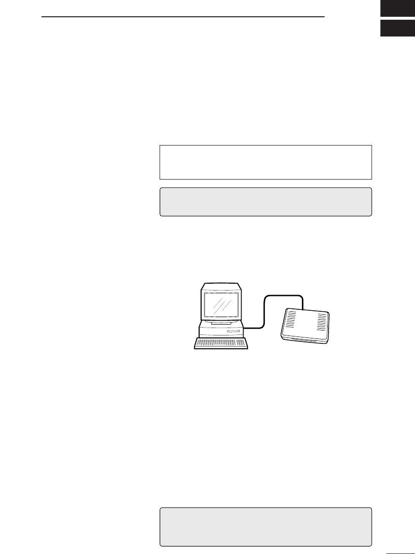
[Checking the Mac address]
1. Select [Control Panel] from the [Apple Menu]. The
open [Apple Talk]. One of the following two screens is
displayed.
* To arrange for the screen on the right to be shown,
select [User Modes] from the [Edit] menu (on the
menu bar) and select the [Specify details] option.
2. Select [Ethernet] for the [Passageway].
3. Display the screen shown below by selecting [Show
Information] from the [File] menu when working with
the left-hand screen shown above or by clicking the
<Information> button when working with the right-hand
screen shown above.
MAC address
AP-3 SETTINGS 6
37
6-1 Before Getting Started
Disconnect the network computers from the AP-3 unit
if you are starting up the AP-3 unit for the first time
after purchasing it or after initializing all setting data.
Connect only the computer than will be used for to
adjust the settings. The connection can be wired or
wireless.
If the AP-3 unit is connected to a working network with-
out changing the original factory settings, IP address
conflicts and other network problems may occur.
6-2 Preparing to Adjust the Settings with a Cable Connection
ÅConnections See “4-1 Connecting to a Computer” (☞p. 14) regarding
how to connect the computer to the AP-3.
Setting terminal AP-3
Ethernet cable
ıStarting the AP-3
and computer
1. After connecting the cable, connect the provided AC
adapter to the DC jack of the AP-3 and plug it into an
outlet. The AP-3 unit will power on. (☞section 4-3, p.
16)
• At first all lamps on the front panel will illuminate, then
only the [POWER] lamp will remain on.
2. Start up the computer.
• If the connection is established normally, the [LAN]
lamp (☞p. 6) on the front panel of the AP-3 will illu-
minate.
* If the [LAN] lamp does not illuminate set the
[HUB/PC] switch to [PC]. (☞pp. 6 and 14)
[IMPORTANT]
When the computer is connected to the AP-3 through a hub, do not
start up any computer other than the computer being used to adjust
the settings (setting terminal) until the settings are completed.
[NOTE]
If possible, use a cable connection between the AP-3 and the com-
puter used to adjust the settings.
AP-3 SETTINGS
6
38
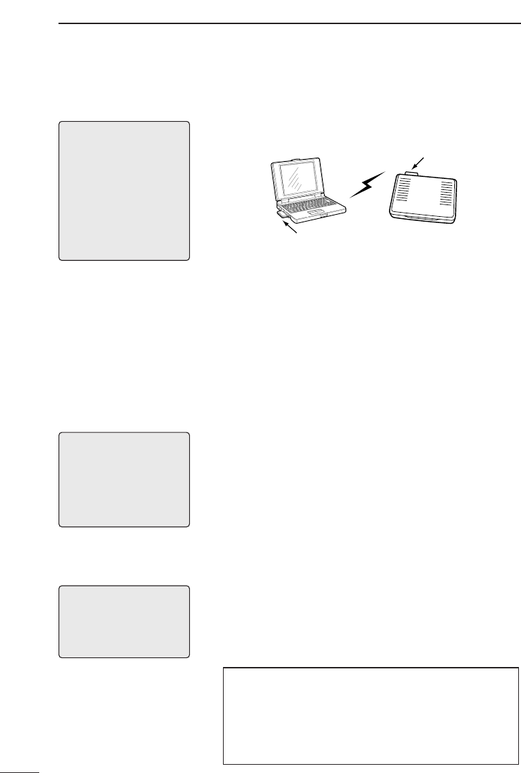
6-3 Preparing to Adjust the Settings with a Wireless Connection
[NOTE]
• If an ICOM SL-1100 wire-
less LAN card is used with
the AP-3, the same model
of wireless LAN card (SL-
1100) must be used with
the computer being used to
adjust the settings.
• A Macintosh computer can-
not be used as a wireless
terminal.
ÅConnections See “4-1 Connecting to a Computer” (☞p. 14) regarding
how to set up the wireless connection between the com-
puter and the AP-3.
Wireless LAN card
Wireless LAN card
Setting terminal AP-3
The items listed below need to be confirmed in order
to establish a wireless connection between the set-
ting terminal and the AP-3 unit. See the instruction
manual provided with your ICOM wireless LAN card
for details.
●Make sure the driver for the ICOM wireless LAN card is
installed.
●Check the [ESS ID] and [Network Mode] of the wireless
LAN card.
●Check the TCP/IP protocol settings.
When the AP-3 will be connected to a working net-
work, check the following items in addition to those
listed above:
●Check the Microsoft Network Sharing Service.
●Check the identification information (work group).
●Check the shared folders.
ıSetting terminal
settings
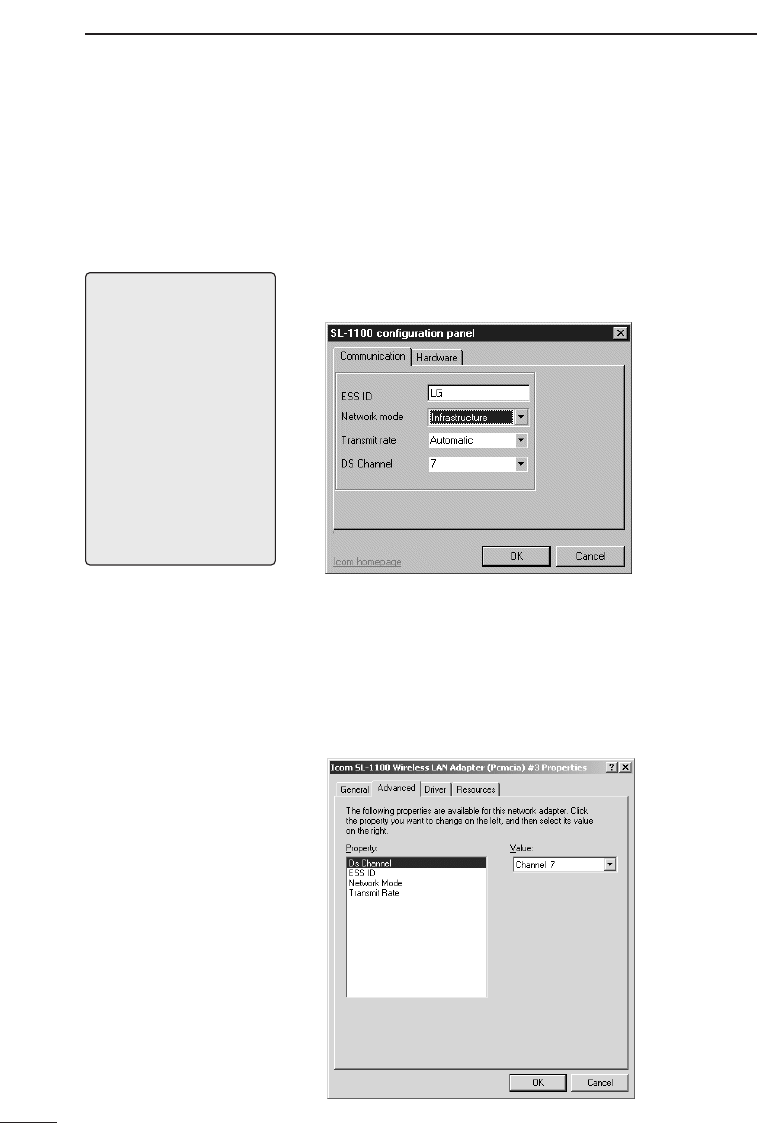
ı-1 Network Mode The [Network Mode] of the AP-3 is factory set to sup-
port the kind of wireless access point function (☞p.
45) illustrated above. Make sure the wireless LAN
card used with the setting computer is also set to the
correct mode (e.g., “Infrastructure” if using an SL-
1100 or SL-1105 LAN card) for connecting to an
access point. (☞p. 39)
[NOTE]
If you are using Windows
2000, “Microsoft Network
Sharing Service” will be
expressed as “Microsoft
Network File and Printer
Sharing”
[NOTE]
If you are using an ICOM SL-
1100 wireless LAN card,
[Network Mode] will be called
[Wireless station type].
The computer will not be able to establish a wireless
connection with the AP-3 unit if the wireless LAN card
used with the setting terminal is set to the mode for
communication between wireless terminals (e.g.,
“Adhoc” mode if using an SL-1100 or SL-1105 LAN
card).
AP-3 SETTINGS 6
39
ı-2 ESS ID The [ESS ID] is used to prevent unauthorized access
to the wireless network group.
The [ESS ID] of both AP-3 unit and the wireless LAN card
are factory set to “LG” (upper gas letters).
The computers that will have a wireless connection with
the AP-3 and the other computers in the same network
group must have the same [ESS ID]. Otherwise the
devices will not be able to communicate.
ı-3 Checking the
settings
Check the [Network Mode] and [ESS ID] settings
using the setting screen.
Be sure to restart the computer if you change any set-
ting values. Otherwise the new settings will not be effec-
tive and the computer will not be able to make the wire-
less connection with the AP-3 unit.
However, restarting is not necessary if the Utility provid-
ed with the LAN card is used to change the settings.
See the instruction manual provided with the wireless
LAN card for more information.
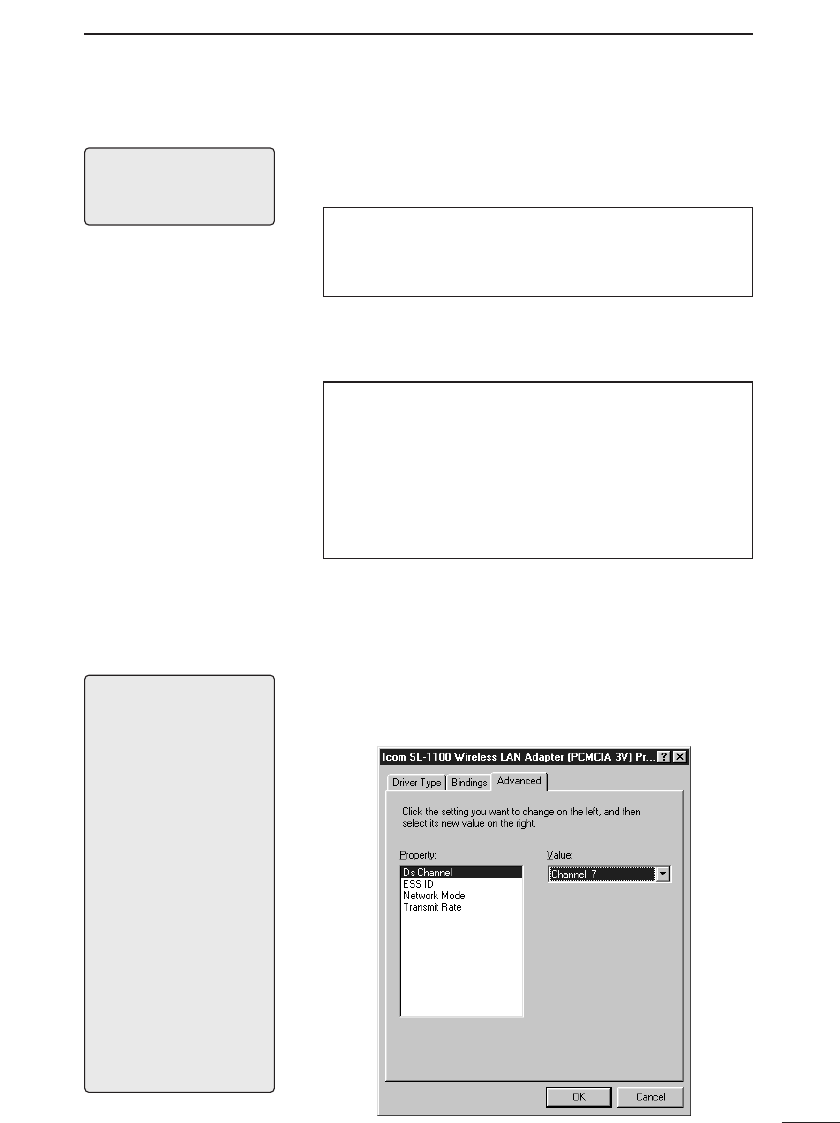
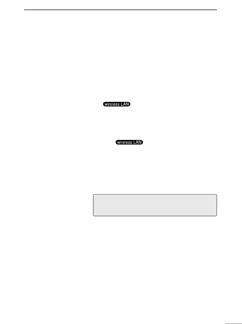
[Windows 98]
Click <Start> and select [Control Panel] from the
[Settings] menu. Double click the [Network] icon. Then
double click “Icom SL-1100 Wireless LAN Adapter (PCM-
CIA 3V)” in the list of installed components.
Select the [Advanced] tab on the adapter properties
screen. The screen will appear as shown below.
[NOTE]
• If the driver for the ICOM
wireless LAN card has not
been installed in the com-
puter, “Icom SL-1100
Wireless LAN Adapter
(PCMCIA 3V)” will not be
included in the list of net-
work components and it will
not be possible to display
the screen shown to the
right (illustrating Windows
98).
See the instruction manual
provided with the wireless
LAN card for more informa-
tion about the setting
screen and installing the
driver.
• If you are using Windows
95, the items displayed
under [Property] will be dif-
ferent.
[NOTE]
If you are using an ICOM SL-
100 wireless LAN card, [ESS
ID] will be called [Net key].
AP-3 SETTINGS
6
40
6-3 Preparing to Adjust the Settings with a Wireless Connection (continued)
ı-3 Checking the settings (continued)
[Windows NT 4.0]
Click <Start> and select [Control Panel] from the
[Settings] menu. Then double click the [Network] icon and
select the [Adapters] tab. Finally, double click “Icom SL-
1100 Wireless LAN Adapter (PCMCIA 3V)” in the list
under [Network adapters].
The screen will appear as shown below.
[Windows 2000]
Click <Start> and select [Dial-Up Networking] from the
[Settings] menu. Double click the appropriate [Local Area
Connection] icon on the [Dial-Up Networking] screen and
then click <Properties>. Click <Configuration> and select
the [Advanced] tab.
The screen will appear as shown below.
[NOTE]
If the driver for the ICOM
wireless LAN card has not
been installed in the comput-
er, “Icom SL-1100 Wireless
LAN Adapter (PCMCIA 3V)”
will not be included in the list
of network adapters and it
will not be possible to display
the screen shown to the
right.
See the instruction manual
provided with the wireless
LAN card for more informa-
tion regarding installing the
driver.
AP-3 SETTINGS 6
41
ÇStarting the AP-3
and computer
1. After completing the setting terminal settings (☞p. 38),
insert the wireless LAN card into the PCMCIA slot of
the AP-3 unit.
2. Connect the provided AC adapter to the DC jack of the
AP-3 and plug it into an AC outlet (☞section 4-3, p.
16). The AP-3 will power on.
• At first all lamps on the front panel will illuminate, then
only the [POWER] lamp will remain on.
3. Start up the computer (setting terminal). Do not start
any other computers in the network.
* If the connection is established normally, the
lamp (☞p. 6) on the front panel of the
AP-3 will illuminate.
* The green lamp of the wireless LAN card inserted
into card slot of the computer (setting terminal) will
flash continuously. The red lamp will flash when the
computer accesses the AP-3 unit.
* If the lamp on the front panel does not
illuminate, check the [Network Mode] and [ESS ID]
settings of the computer or restart computer. (☞pp.
38, 39 and 40)
* If the lamps of the wireless LAN card inserted into the
card slot of the computer do not illuminate or do not
behave as described above, check if the driver is
installed properly.
[IMPORTANT]
When the computer is connected to the AP-3 through a hub, do not
start up any computer other than the computer (setting terminal)
being used to adjust the settings until the settings are completed.
AP-3 SETTINGS
6
42
6-4 Accessing the Setting Screen
After connecting the computer (setting terminal) to
the AP-3 unit according to the instructions in section
6-2 or 6-3, make sure you can access the setting
screen of the AP-3 using the web browser of the com-
puter.
Install a web browser into the computer if it does not
already have one.
1. Open the web browser of the setting terminal.
2. Designate the IP address of the AP-3 unit as the URL.
• http://192.168.0.1 (original factory setting)
3. When the setting terminal gains access to the AP-3
unit, the [Wireless LAN Setting] screen is displayed.
* If the setting screen is not displayed, check the set-
tings, connections, and IP address settings (☞p. 34)
of the setting terminal. Restart the setting terminal
and try to access the AP-3 again.
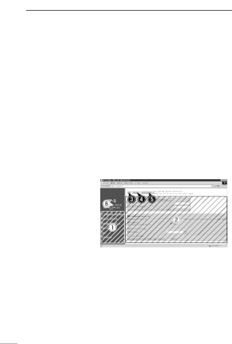
[Wireless LAN Setting Screen]
qSetting screen
selection area ·········· This area displays the titles of all AP-3 setting screens.
Click the title of the desired setting screen to open it.
wSetting screen
display area·············· This area displays the selected setting screen.
e<Save> button·········· Click this button to save changes made to the data dis-
played on the setting screen.
AP-3 SETTINGS 6
43
r<Cancel> button ······ Click this button to cancel any changes and return the
setting data to its original state (i.e., state before changes
were made). If the <Save> button has been pressed, the
settings will not return to their original state.
t<Save and Restart>
button ······················· Click this button to save the setting changes and restart
the AP-3 unit.
* After the settings have been saved, a message sug-
gesting restarting the unit will be displayed next to this
button if restarting is required. Be sure to click this but-
ton when this occurs.
yVersion
information··············· This area shows the version of the firmware (☞p. 66).
This manual assumes Version 1.0 is being used.
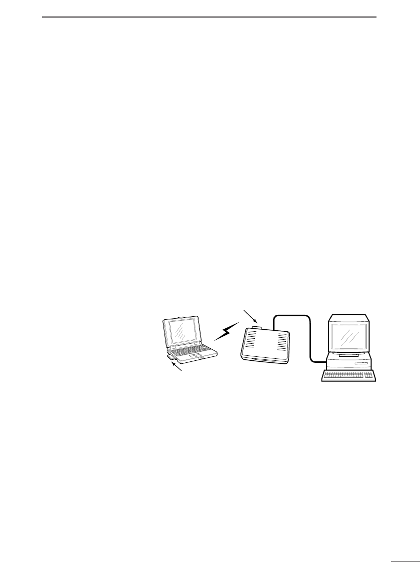
6-5 Testing the Operation
Set up the connection arrangement shown below and
check if a wireless connection with the AP-3 can be
made.
* The settings of the AP-3 unit are assumed to be original
factory settings.
PC
Ethernet cable
Wireless LAN card
Wireless LAN card
Wired terminal
AP-3
1. Insert the wireless LAN card into the AP-3 unit. (☞p.
10)
2. Connect the provided AC adapter to the AP-3 unit.
• At first all lamps on the front panel will illuminate, then
only the [POWER] lamp will remain on.
3. Start up the wired terminal (connected with an Ethernet
cable).
• The [LAN] lamp (☞p. 6) on the front panel of the AP-
3 will illuminate.
4. Make sure you can access the setting screen of the
AP-3 from the wired terminal. (☞p. 42)
5. Create a test folder and set the shared folder permis-
sion so that the folder can be shared.
·············································Continued on following page

AP-3 SETTINGS
6
44
6-5 Testing the Operation (continued)
6. Start up the wireless terminal (in which a wireless LAN
card has been inserted). (☞6-3, p. 38).
• If the connection is normal, the lamp
(☞p. 6) on the front panel will illuminate.
7. Make sure you can access the setting screen of the
AP-3 from the wireless terminal (☞p. 42).
8. Create a test folder and set the shared folder permis-
sion so that the folder can be shared.
9. Double click the [Network Computer] icon on both the
wired terminal and the wireless terminal. The wireless
access point is functioning properly if both computers
display an icon for the other computer.
* If using Windows 2000, [Network Computer] is called
[My Network].
10. From each computer (wired and wireless), double
click the icon for the other computer. The newly cre-
ated test folder should appear.
11. After completing these steps, refer to Chapter 8 and
set up the AP-3 so it can be used in the working net-
work. Then connect the AP-3 to the network.
WIRELESS FUNCTIONS 7
45
The AP-3 unit can function in the following two ways
to construct a wireless network:
• Wireless access point function (☞section 7-1 below)
• Roaming function for roaming with a wireless terminal
(☞section 7-2, p. 46)
* When a wireless transmission speed of 11 Mbps is
used, the transmission range is roughly 30 m indoors
and 70 m outdoors (line of sight).
[NOTE]
A Macintosh computer cannot be used as a wireless
terminal.
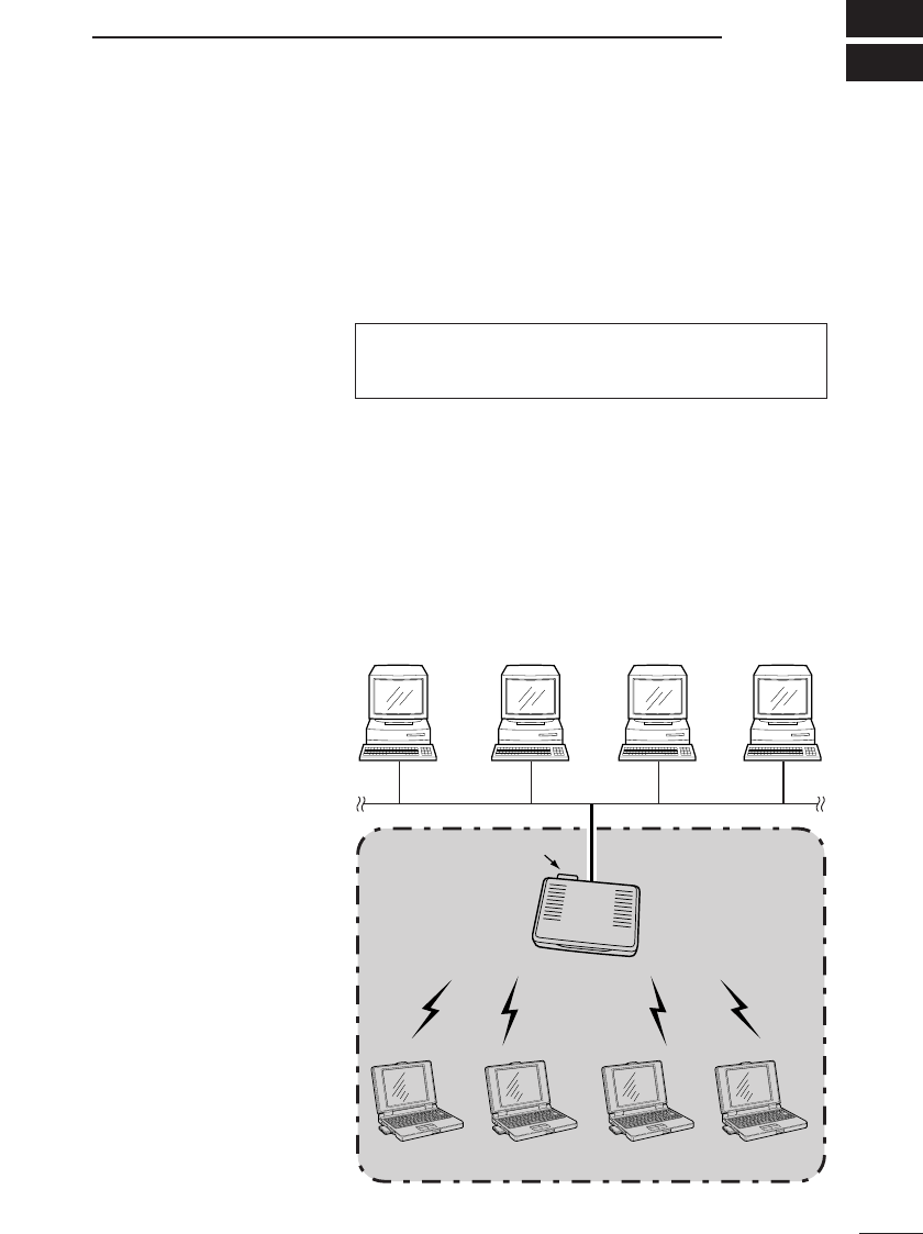
7-1 Wireless Access Point Function
The wireless access point function refers to using the
AP-3 unit to construct a local area network wherein
wireless terminals can communicate with each other
as well as with wired terminals connected to the AP-
3 via an Ethernet cable.
■Schematic
illustration
AP-3
Wired LAN
LAN
Up to 256 wireless terminals can be connected.
Wireless
transmission area Wireless
transmission area
Wireless LAN card
Ethernet LANEthernet LAN
WIRELESS FUNCTIONS
7
46
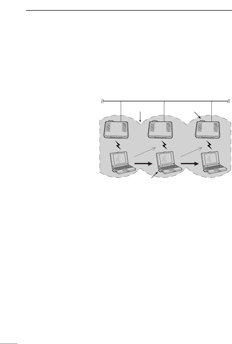
7-2 Roaming Function
Ethernet LAN
Wireless transmission
area
AP-3 AP-3 AP-3
Moves Moves
Switches AP-3 unitsSwitches AP-3 units
Wireless LAN card
Wireless LAN card
The roaming function refers to installing multiple AP-
3 units along an Ethernet LAN so that the wireless
transmission areas overlap. This arrangement allows
wireless terminal to maintain communications with
the Ethernet LAN while moving among the wireless
transmission areas. In short, this function allows the
wireless transmission area to be expanded.
■Schematic
illustration
■Roaming function
precautions
●Overlapping of IP addresses can be avoided by setting
up only one of the AP-3 units so that the DHCP server
function is enabled.
●Within the mobile wireless transmission area (roaming
area), all wireless terminals and AP-3 units for which
the roaming function will be used must use the same
[ESS ID] setting.
Wireless terminals set to a different [ESS ID] will not be
able to communicate with the AP-3 units.
●The wireless LAN terminals, including those in the
roaming area, will operate as part of the same network
group as wired LAN terminals. Therefore, routing mode
(☞p. 51) cannot be used when the roaming function is
used.
●When SL-1100 or SL-1105 LAN cards are used and
roaming is conducted using the same channel for all
LAN cards, the transmission speed may decline in the
interference areas where the signals from two wireless
access points (i.e., AP-3 units) can be received simul-
taneously. To avoid interference completely, set the
channels of the AP-3 units at least four channels apart.
●Connect the AP-3 units in a cascade arrangement by
connecting them through a hub using Ethernet cable.
SETTING SCREENS 8
47
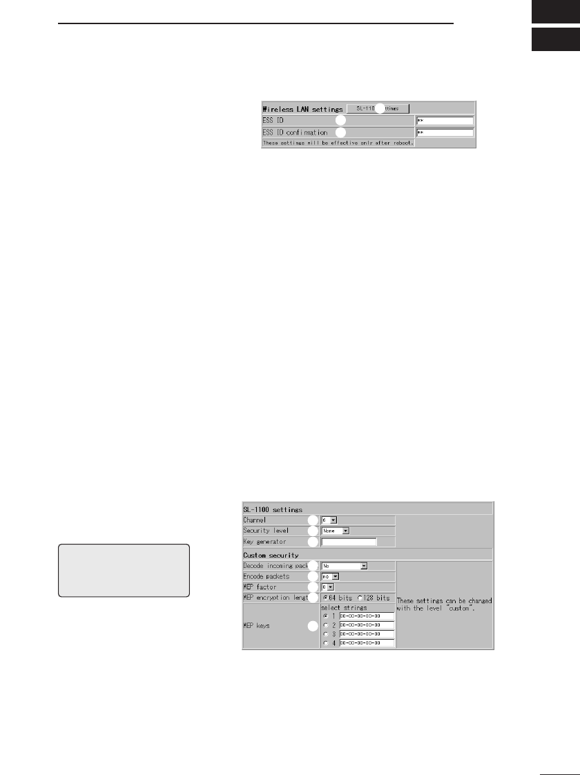
8-1 [Wireless LAN Settings] Screen
■Wireless LAN
settings
w
q
e
q<SL-1100 or SL-1105
advanced settings>
button ······················· Click this button to open an advanced LAN card setting
screen when an SL-1100 or SL-1105 wireless LAN card is
used with the AP-3.
wESS ID······················· This setting item is used to establish an ID to prevent
unauthorized access to the wireless LAN connected to
the AP-3 unit. A wireless connection can only be made
between AP-3 units having the same ESS ID or between
an AP-3 unit and a wireless terminal having the same
ESS ID.
Setting changes will not take effect until the AP-3 unit is
restarted.
When entering the ESS ID, use up to 31 arbitrary
alphanumeric characters. Upper and lower case are dis-
tinguished. (Default setting: LG)
Typed characters are displayed as asterisks (*).
(Display example: **)
eESS ID Confirmation
Reentry ····················· This setting item is for reentering the ESS ID to make
sure it is entered correctly with no typographical errors.
Be careful to distinguish between upper and lower case
letters. (Display example: **)
■SL-1100 or SL-1105
advanced settings
q
w
e
r
t
y
u
i
[NOTE]
Only when the channel set-
ting is changed does the AP-
3 unit need to be restarted.
qChannel ···················· This setting item is used to set the wireless transmission
channel used for the wireless connection of the AP-3.
(default value: 14)
* Wireless terminals using an SL-1100 or SL-1105 wire-
less LAN card will automatically detect the channel set-
ting of the AP-3.
·············································Continued on following page
e.g. SL-1100

SETTING SCREENS
8
48
8-1 [Wireless LAN Settings] Screen (continued)
■SL-1100 or SL-1105 advanced settings (continued)
wSecurity Level·········· This setting item is used to set the degree of data encryp-
tion used to protect the data transmitted over the wireless
network. (default setting: None)
The AP-3 uses WEP (wired equivalent privacy) encryp-
tion.
Except for [WEP Key], all setting items under [Security
Level Custom Settings] are set automatically according to
the security level (Low, Medium, or High) selected here.
When this setting item is set to “Custom” the setting items
(except WEP Key) under [Security Level Custom
Settings] can be set arbitrarily.
* We recommend using the same security level for
devices that will be communicating with each other.
However, a wireless terminal with a security setting of
“Medium” can communicate with another wireless or
wired terminal through an AP-3 unit with a security set-
ting of “Low.”
eKey Generator·········· This setting item is used to enter a character string for
generating the key used for encryption and decryption.
Typed characters are displayed as asterisks (*).
(Display example: **)
The keys generated from the entered character string are
displayed in the WEP Key text boxes under [Security
Level Custom Settings].
* Enter the same character string (arbitrary combination
of alphanumeric characters and symbols for which
upper and lower case letters are distinguished) as the
other devices with which AP-3 will be communicating. If
different character strings are used, the encrypted data
cannot be decrypted.
rDecryption of
Received Packets···· This setting item is related to the decryption of received
packets. Select from among “Yes”, “No” and “Yes (destroy
unencrypted packets)” (default value: No)
tEncryption of Trans-
mitted Packets········· This setting item is related to the encryption of received
packets. Select “Yes” or “No.” (default value: No)
·············································Continued on following page

SETTING SCREENS 1
49
yWEP Factor ·············· This setting item is used to establish the security level. “0”
indicates the highest degree of security.
(default value: 0)
The encryption levels are as follows:
“0”= updates internal encryption key for every packet
“1”= updates internal encryption key every five packets
“2”= updates internal encryption key every ten packets
“3”= updates internal encryption key every fifty packets
uNumber of
Encryption Bits········ This setting item is used to select the number of encryp-
tion bits. (default value: 64)
When “64 bits” is selected, the last 40 bits of the keys are
shown in the [WEP Key] text boxes.
When “128 bits” is selected, the last 104 bits of the keys
are shown in the [WEP Key] text boxes.
( The leading 24 bits are not displayed.
iWEP Key··················· When 64-bit encryption is selected, the keys generated
from the character string entered into the [Key Generator]
text box are displayed in text boxes 1, 2, 3, and 4 in 40-
bit segments. When 128-bit encryption is selected, the
keys are displayed in 104-bit segments.
Only the selected key (1, 2, 3, or 4) is used for encryption.
Select a key by putting a check in the adjacent check box.
The other device can only decrypt the signal from the AP-
3 when it is encrypting with one of the four keys (1, 2, 3,
or 4) shown here.
* The keys can also be entered directly into the WEP key
text boxes (1, 2, 3, and 4). When this is done, a charac-
ter string will not be displayed in the [Key Generator]
text box.

SETTING SCREENS
8
50
8-1 [Wireless LAN Settings] Screen
■MAC address
security settings
q
w
e
r
qUse MAC Address
Security ····················
This setting item is used to select whether or not to limit
wireless connections with this AP-3 unit to those wireless
terminals having one of the MAC addresses registered
here. (default value: No)
Setting changes will not take effect until the AP-3 unit is
restarted.
wMAC Address on the
Wireless LAN card···
When the wireless LAN card inserted into the AP-3 is
properly recognized, the MAC address registered on the
wireless LAN card is displayed here.
eMAC Address··········· When the MAC Address Security function is used, the AP-
3 unit can communicate with other ICOM network devices
fitted with a wireless LAN card whose MAC address set-
ting matches one of the MAC addresses registered here.
* A maximum of 256 different MAC addresses can be reg-
istered.
* Enter 12 alphanumeric characters for each address.
* After entering the address, click <Add>. Them make
sure the new address appears in the [Current Registry].
* Hyphens are not recognized as part of the address.
Thus, the following two entries represent identical
address values:
11-11-11-22-33-33 111111223333
* See section 5-3 (☞p. 34) for instructions on how to
check the MAC address of a wireless LAN card.
r<Delete> button ······· This button is used to delete a previously registered MAC
address. When no MAC addresses are registered, this
button is not displayed.
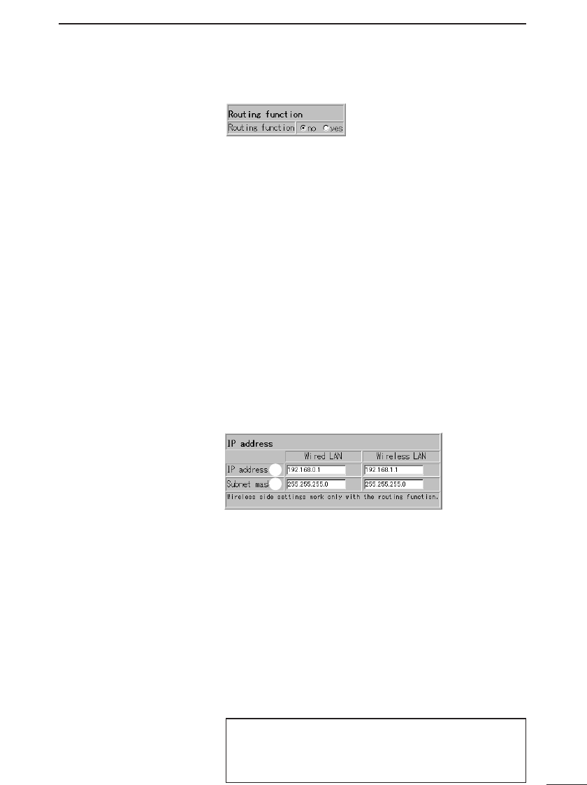
SETTING SCREENS 8
51
■Routing mode
setting
8-2 [AP-3 Network Settings] Screen
Using Routing Mode This setting item is used to set whether or not routing will
be used between the wired LAN and the wireless LAN.
(default setting: No)
It is necessary to restart the AP-3 unit to activate any set-
ting changes.
* When “No” is selected, the wired LAN and the wireless
LAN are handled as though they are in the same subnet
(i.e., same network) and, therefore, the roaming func-
tion (☞p. 46) can be used. In this case, the IP address
and subnet mask settings under [Wired LAN] on the
[AP-3 Network Settings] screen are used for the wire-
less LAN.
When “Yes” is selected, the wired LAN and the wireless
LAN are handled as though they are in different subnets
(i.e., separate networks). In this case, the IP address
and subnet mask settings under [Wireless LAN] on the
[AP-3 Network Settings] screen are used for the wire-
less LAN.
■AP-3 IP address
settings
q
w
qIP address •••••••••••• This setting item is used to set the wired LAN and wire-
less LAN IP addresses.
●Wired LAN default setting : 192.168.0.1
●Wireless LAN default setting : 192.168.1.1
Setting changes will not take effect until the AP-3 unit is
restarted.
wSubnet mask•••••••••• This setting item is used to set the wired LAN and wire-
less LAN subnet masks.
●Wired LAN default setting : 255.255.255.0
●Wireless LAN default setting : 255.255.255.0
Setting changes will not take effect until the AP-3 unit is
restarted.
When the [Routing Mode Setting] is set to “No” (default),
the AP-3 unit will operate using the IP address and sub-
net mask entered under [Wired LAN] for the wireless
LAN.
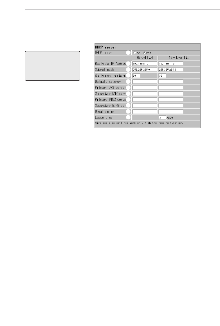
SETTING SCREENS
8
52
8-2 [AP-3 Network Settings] Screen (continued)
[NOTE]
The AP-3 unit must be
restarted before any of the
settings on this screen will
take effect.
■DHCP server settings
q
w
e
r
t
y
u
i
o
!0
!1
qUse DHCP Server
Function ··················· This setting item is used to set whether the AP-3 unit will
be used as a DHCP server or not. (default value: Yes)
When the AP-3 is used as a DHCP server, the following
information regarding the DHCP server clients can be set
automatically:
●IP address
●Subnet mask
●Default gateway
●DNS server
●WINS server
●Domain name
wInitial Allocation IP
Address ···················· This setting item is for setting the initial IP address that
will be used when the AP-3 unit allocates IP addresses to
computers connected with either a wired or a wireless
connection.
●Default value for wired LAN side :192.168.0.10
●Default value for wireless LAN side :192.168.1.10
eSubnet Mask ············ This setting item is the subnet mask corresponding to the
allocation starting IP address.
(default value: 255.255.255.0)
·············································Continued on following page

SETTING SCREENS 8
53
rNumber of
Allocations ··············· This setting item establishes the maximum number of IP
addresses that can be automatically allocated in succes-
sion starting with the initial allocation address.
(default value: 30)
Setting values from 5 to 128 are allowed.
tDefault Gateway ······ This setting item establishes the default gateway that will
be reported to the client. Enter values for both the wired
LAN and the wireless LAN.
yPrimary DNS
Server ······················· This setting item establishes the primary DNS address for
both the wired LAN and the wireless LAN.
uSecondary DNS
Server ······················· This setting item establishes the secondary DNS address
for both the wired LAN and the wireless LAN.
iPrimary WINS
Server ······················· This setting item establishes the primary WINS address
for both the wired LAN and the wireless LAN.
oSecondary WINS
Server ······················· This setting item establishes the secondary WINS
address for both the wired LAN and the wireless LAN.
!0 Domain Name··········· This setting item establishes the domain name of the net-
work address reported to the client by the DHCP server.
Enter values for both the wired LAN and the wireless
LAN.
!1 Lease Period ············ This setting item establishes the frequency (in days) at
which the DHCP server will automatically reallocate a
new local IP address to the client. Enter values for both
the wired LAN and the wireless LAN. (default value: 3)

SETTING SCREENS
8
54
8-2 [AP-3 Network Settings] Screen (continued)
■Static DHCP server
settings
This section of the [AP-3 Network Settings] screen is
used to specify the wired and wireless terminals to which
IP addresses will be automatically allocated using the
DHCP server function. The computers are registered
according to MAC address and IP address.
* Enter 12 alphanumeric characters for each MAC
address.
* Hyphens are not recognized as part of the address.
Thus, the following two entries represent identical MAC
addresses:
11-11-11-22-33-33 111111223333
* Up to 16 wired and wireless terminals can be registered.
The IP addresses registered here must be outside the
range of IP addresses that can be allocated by the
DHCP server function.
* After typing the MAC address and IP address, click
<Add> under “Wired” or “Wireless” and make sure the
new addresses have been registered under [Current
Registry].
[NOTE]
The AP-3 unit must be
restarted before any of the
settings on this screen will
take effect.
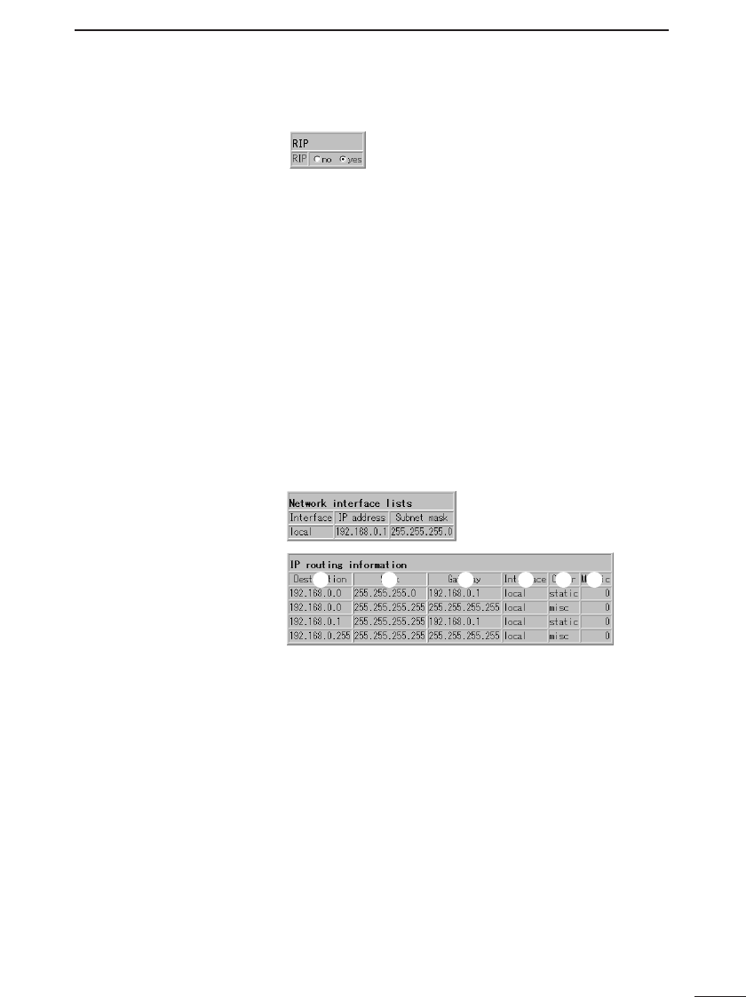
SETTING SCREENS 8
55
8-3 [Routing Settings] Screen
■RIP setting
When RIP is used, the AP-3 exchanges routing informa-
tion with nearby routers and access points to dynamical-
ly create a communication path. RIP packets are broad-
cast approximately every 30 seconds using the broadcast
addresses of those routers and access points.
(default value: Yes)
A setting change will not take effect until the AP-3 unit is
restarted.
■IP routing
information
This table displays information regarding which terminal,
access point, or router the packet should be distributed to
when the AP-3 transmits a packet. Paths added using the
[Static Routing Settings] (☞p. 57) are also displayed
here.
q w erty
qDestination··············· This column shows the destination IP address of the
packet being routed.
wNet Mask··················· This column shows the net mask corresponding to the
destination IP address of the packet being routed.
eGateway···················· This column shows the gateway corresponding to the
destination IP address of the packet being routed.
·············································Continued on following page

SETTING SCREENS
8
56
8-3 [Routing Settings] Screen (continued)
■IP routing information (continued)
rNet····························· This item displays added IP routing information in the
[Network Interface List].
• Interface
This column shows the transfer destination interface
corresponding to the destination IP address of the pack-
et being routed.
• IP Address
This column shows the IP address of the transfer desti-
nation.
• Net Mask
This column shows the net mask of the transfer desti-
nation.
tCreation Type··········· This column shows how the routing information was
made.
• static
Indicates that the routing information was created using
a static (defined) route.
• rip
Indicates that the routing information was created using
a dynamic (automatically generated) route.
• misc
Indicates that the routing information is related to the
broadcast.
yMetric························ This column displays the number of routers and access
points (or gateways) that the packet will pass through
before reaching its destination.
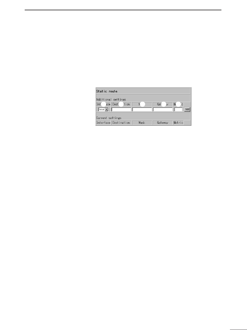
SETTING SCREENS 8
57
8-3 [Routing Settings] Screen (continued)
■Static routing
settings
This table is used to specifically define the routing path of
a packet. Up to 20 paths can be registered.
* After entering a path, click <Add> and make sure the
path is displayed in the [Current Registry]. The setting
data should also appear on the [IP Routing Information]
screen.
q w ert
qPath··························· • local
Select “local” when the [Routing Mode] (☞p. 51) is not
used. Indicates that the routing information to be regis-
tered is for the LAN.
• ethernet
Select “ethernet” when the [Routing Mode] is used.
Indicates that the routing information to be registered is
for the wired LAN.
• wireless
Select “wireless” when the [Routing Mode] is used.
Indicates that the routing information to be registered is
for the wireless LAN.
wDestination ·············· Enter the IP address of the target destination in accor-
dance with the selected path (ethernet, wireless, or local).
eNet Mask··················· Enter the net mask corresponding to the IP address of the
target destination in accordance with the selected path
(ethernet, wireless, or local).
rGateway···················· Enter the gateway for the transfer destination (router or
access point) of the packet to be routed.
tMetric Value·············· Enter the number of routers and access points (or gate-
ways) that the packet will pass through before reaching
its destination.
Values from 0 to 16 may be entered.
The AP-3 interprets a small number as indicating that the
circuit has a high transfer capacity.

SETTING SCREENS
8
58
8-4 [AP-3 Management Settings] Screen
■Manager ID settings
Enter an arbitrary name for the network manager using
up to 31 alphanumeric characters. Upper and lower case
letters are distinguished. (Example ID: AP-3)
A user name will be requested the next time the AP-3 unit
is accessed after completing this setting. Enter this man-
ager ID.
wManager Password·· Enter an arbitrary password using up to 31 alphanumeric
characters. Upper and lower case letters are distin-
guished. (Display example: ****)
Typed characters will appear as asterisks (*).
A password will be requested the next time the AP-3 unit
is accessed after completing this setting. Enter this man-
ager password.
ePassword Confirma-
tion Reentry ············· This setting item is for reentering the manager password
to make sure it is entered correctly with no typographical
errors. (Display example: ****)
q
w
e
qManager ID···············
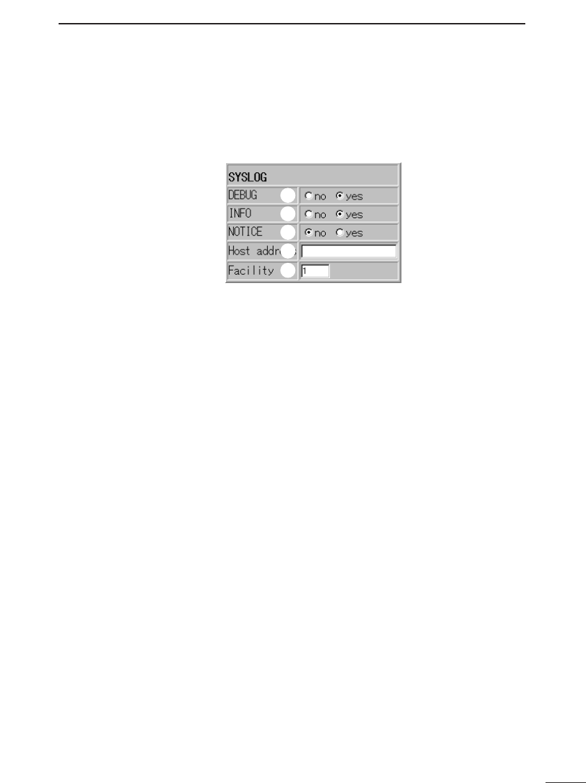
SETTING SCREENS 8
59
■SYSLOG settings When log information and the like is managed using SYS-
LOG host, the information can be managed collectively as
a file using the SYSLOG function. These SYSLOG set-
tings are used to select what information will be output as
part of the SYSLOG.
q
w
e
r
t
qUse DEBUG·············· This setting item is for selecting whether or not debug
information will be output as part of the SYSLOG.
(default value: Yes)
wUse INFO ·················· This setting item is for selecting whether or not INFO type
messages will be output as part of the SYSLOG.
(default value: Yes)
eUse NOTICE ············· This setting item is for selecting whether or not NOTICE
type messages will be output as part of the SYSLOG.
(default value: No)
rHost Address ··········· When the SYSLOG function will be used, enter the
address of the host that will receive the SYSLOG.
The host must support SYSLOG server functions.
tFacility ······················ Enter the SYSLOG facility. (default value: 1)
Set to a value from 0 to 23.
This setting item is normally set to “1.”

SAVING AND UPLOADING SETTING DATA
9
60
9-1 [Save Settings] Screen
The [Save Settings] screen is used to copy setting
data from the AP-3 to a floppy disk or the hard disk of
a computer and to upload setting data from a com-
puter to the AP-3.
q w e
r
q<Register to AP-3>
button ······················· This button is used to copy the setting data shown on the
[Save Settings] screen to the setting screen of the AP-3.
w<Undo> button········· This button is used to undo any changes made to the set-
ting data shown on the [Save Settings] screen and return
the data to the state it was in when the file was first
opened.
e<Return to Menu>
button ······················· This button is used to return to the [Wireless LAN
Settings] screen.
rDisplay area ············· When the [Save Settings] screen is opened from the AP-
3 setting screen, the current setting data is displayed in
this area.
When the [Save Settings] screen is opened from a data
file according to the procedure in “9-3 Uploading Setting
Data” (☞p. 62), the setting data stored in the data file is
displayed.
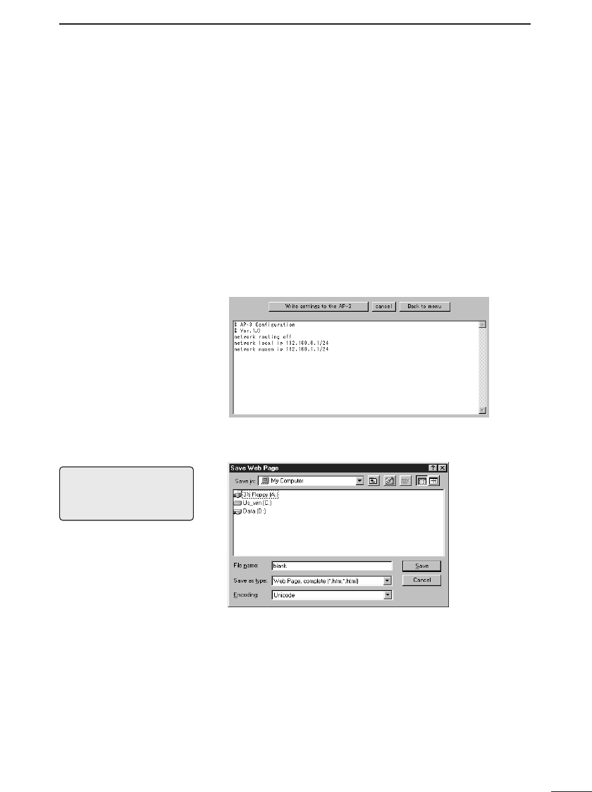
SAVING AND UPLOADING SETTING DATA 9
61
9-2 Saving Setting Data
Follow the procedure below to save the current set-
ting data as an HTML file onto a floppy disk or the
hard disk of the computer being used to access the
AP-3.
1. Connect a setting terminal (wired or wireless) to the
AP-3.
2. Start up the web browser of the setting terminal.
3. Access the setting screen of the AP-3.
4. Click [Save Settings] in the setting screen selection
area.
• The [Save Settings] screen is displayed as shown
below.
5. Select [Save as] from the [File] menu of the web brows-
er.
6. Designate the directory in the [Save in] text box and
enter a filename in the text box.
7. Select [HTML file] under [Save as type].
* Select JIS if your browser offers a selection of kanji
codes for the file.
8. Click the <Save> button.
• The setting data is stored in the designated location.
* The file extension will be htm or html.
* The file will not have an extension if saved on a
Macintosh.
[Note]
This explanation is based on
Internet Explorer 5.0 for
Windows.
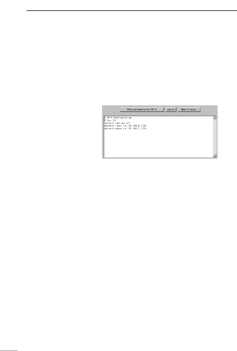
SAVING AND UPLOADING SETTING DATA
9
62
9-3 Uploading Setting Data
Follow the procedure below to upload setting data
from a computer to the AP-3.
1. Connect a setting terminal (wired or wireless) to the
AP-3.
2. From the setting terminal, double click the icon of the
stored data file.
• The [Save Settings] screen is displayed as shown
below.
3. Click the <Register to AP-3> button.
• The setting data is uploaded and the AP-3 restarts.
4. Check that the correct setting data has been uploaded
and close the setting screen.
■Precautions
regarding editing
When editing the network IP address or other setting in
the display area, change the other related setting values
at the same time.
* Read “General Precautions” (☞p. 4) regarding editing
the setting data. Bear in mind that the results of any set-
ting changes will be on your own responsibility.

SETTING DATA INITIALIZATION 10
63
There may be times when you wish to readjust the
settings from the beginning or delete existing setting
data, such as when changing the network configura-
tion. The setting data can be returned to the original
factory settings using one of the three methods (Å,
ı, or Ç) listed below.
This chapter explains Åand ıonly.
ÅUse the <INIT> button (☞p. 63)
ıUse the setting screen (☞p. 65).
ÇUse the Utility (☞p. 67).
* To use the Utility, install it from the included Utility
Software disks. See “12 Utility Software” (☞p. 67) for
instructions regarding how to install the Utility.
ÅUsing the <INIT>
button
Use the following procedure to initialize the setting
data in situations where you cannot access the AP-3
setting screen, such as when the current IP address
setting of the AP-3 is unknown.
1. Disconnect all network devices except the AP-3 unit
and the setting terminal (wired or wireless) that will be
used to conduct the initialization.
2. Hold down the <INIT> button. Then supply power to
the AP-3 unit or lightly press and release the <RESET>
button.
• The [LAN] lamp and the lamp will flash
in unison.
3. Release the <INIT> button when the <POWER> indi-
cator lamp starts flashing.
• The <POWER> lamp will continue to flash slowly
while operating in [Setting Initialization Mode].
4. Start up the setting terminal.
5. Open the web browser of the setting terminal and a
designate the original factory-set IP address (☞p. 42)
of the AP-3 in the URL text box.
• The [Initialize mode] screen is displayed.
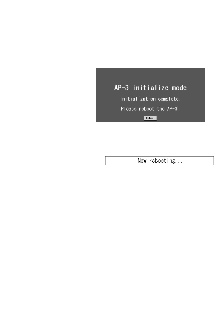
SETTING DATA INITIALIZATION
10
64
ÅUsing the [INIT] button (continued)
6. Click the <Initialize> button on the [Setting Initialization
Mode] screen.
• The following screen is displayed:
7. Click the <Restart> button.
• While the AP-3 unit is restarting, the following mes-
sage is displayed:
8. The initialization is complete when the <POWER>
lamp stops flashing and the [Wireless LAN Settings]
screen is displayed.
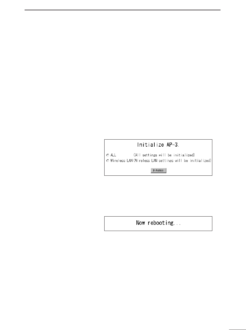
SETTING DATA INITIALIZATION 10
65
ıUsing the setting
screen
Use the initialization procedure described below
when the current IP address is known and the AP-3
setting screen can be accessed. This procedure is
conducted from the [Initialize Settings] screen and
allows the scope of the initialization to be selected.
1. Disconnect all network devices except the AP-3 unit
and the setting terminal (wired or wireless) that will be
used to conduct the initialization.
2. Start up the setting terminal.
3. Open the web browser of the setting terminal.
4. Designate the original factory-set IP address (☞p. 42)
in the URL text box and access the AP-3 setting
screen.
5. Click [Initialize Settings] in the setting screen selection
area (☞p. 42).
• The [Initialize Settings] screen is displayed.
6. Select the radio button next to the desired initialization
option (see below for details).
7. Click the [Initialize] button.
• While the AP-3 unit is restarting, the following mes-
sage is displayed.
8. The initialization is complete when AP-3 unit has
restarted and the [Wireless LAN Settings] screen is
displayed.
■Regarding initializa-
tion options
• Initialize all settings
This option initializes all setting data adjusted from the
setting screen.
• Initialize wireless settings
This option initializes all settings that can be adjusted
from the [Wireless LAN Settings] screens (☞section 8-
1, pp. 47 to 50). Access the [Wireless LAN Settings]
screens by clicking [Wireless LAN Settings] in the set-
ting screen selection area (☞p. 42).

UPDATING THE FIRMWARE
11
66
■About firmware “Firmware” refers to programs written into the flash
memory of the AP-3 at the factory. These programs
help the AP-3 operate.
New versions of these programs are sometimes created
to expand or improve the functions of the product. By
updating these programs, you can add functions and
keep the AP-3 operating at its peak potential.
Before updating the firmware, confirm which version you
are currently using by accessing the AP-3 setting screen.
The firmware version
number is displayed
in the setting screen
selection area (☞p.
42).
Version number
■About the latest
version
Our homepage provides information about firmware
updates.
Check our homepage regularly at
http://www.icom.co.jp/
■Downloading
precautions
●Before downloading, read the license agreement for
using our homepage.
●Firmware for other products cannot be used. Be sure to
download the correct firmware.
●Depending on the content of the update, installing the
latest version of the firmware may require initializing
the setting data. When such is the case, use the Utility
(☞p. 68) to initialize the data after updating the
firmware.
●Conduct the download procedure with the setting ter-
minal connected to the AP-3 unit one-on-one (i.e., all
other network devices disconnected) so that the data
can be transfered in a stable environment.
■How to update ●Use the Utility provided on the Utility Software disks to
update the firmware.
●See “12 Utility Software” (☞p. 67) for instructions on
how to install and operate the software.

UTILITY SOFTWARE 12
67
This chapter explains how to use the Utility software
provided on the Utility Software disks, which are
included in the AP-3 package.
12-1 About the Utility
The Utility is a software application used to initialize
the setting data and update the firmware of the AP-3
unit.
Install the Utility software in a computer having one of the
following operating systems.
●Windows 95, Windows 98
●Windows NT 4.0, Windows 2000
12-2 Installing the Utility
1. Start Windows.
If Windows is already running, close all open applica-
tions.
2. Insert the floppy disk labeled “Utility Software (1/2)”
into the floppy disk drive.
3. Click <Start> and select [Run].
4. Type the name of the floppy disk drive and the filename
Setup.exe. Then click <OK> or press the [Enter] key.
• If the floppy disk drive is drive A, for example, type
“A:\Setup.”
5. Follow the instructions on the screen and inserted the
floppy disk labeled “Utility Software (2/2)” when
requested to do so.
6. Click <OK> and continue following the instructions on
the screen.
7. After completing the installation, remove the floppy
disk from the floppy disk drive.
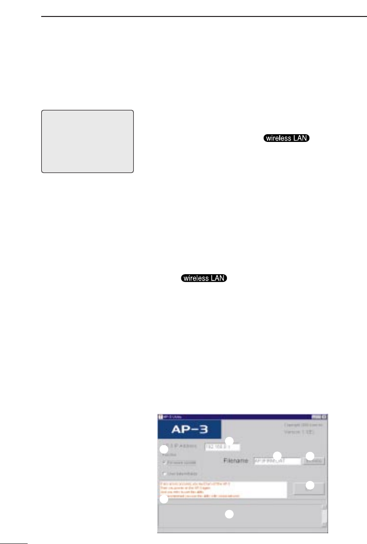
UTILITY SOFTWARE
12
68
12-3 Using the Utility
In order to communicate with the Utility, the AP-3
must be started up in [Update Mode] according to the
following procedure:
1. Hold down the <MODE> button. Then supply power to
the AP-3 unit or lightly press and release the <RESET>
button.
• The [LAN] lamp and the lamp will flash
in unison.
2. Release the <MODE> button when the <POWER>
indicator lamp starts flashing.
• The <POWER> lamp will continue to flash rapidly
while operating in [Setting Initialization Mode].
[NOTE]
When the AP-3 is started up
in [Update Mode], the WEP
function (i.e., wireless LAN
security level) will become
ineffective automatically.
ıConnect the setting
terminal (computer)
After the AP-3 has been started up in [Update Mode],
connect the setting terminal (wired or wireless) con-
taining the Utility software to the AP-3 unit one-on-
one (i.e., all other network devices disconnected).
• The [LAN] lamp will illuminate if the setting terminal has
a wired connection with the AP-3.
• The lamp will illuminate if the setting ter-
minal has a wireless connection with the AP-3.
* IP address conflicts and other network disruptions may
occur if the setting data is initialized or the firmware is
updated from a terminal connected to an operating net-
work.
ÇStart up the utility From Windows, click <Start> and select this Utility
from the [Program] menu. The [AP-3 Utility] screen is
displayed.
[AP-3 Utility] screen
q
wer
t
y
u
ÅStart up the AP-3 in
[Update Mode]

UTILITY SOFTWARE 12
69
ÎOperate the utility The procedures for operating the [AP-3 Utility] screen
are explained below. Encircled numbers refer to the
reference numbers shown in the screen shot on page
68.
[EXTREMELY IMPORTANT]
Never turn off the power to the AP-3 unit while it is
restarting after initializing the user data (setting
data) or updating the firmware (☞p. 70 and 71).
If the power is turned off before the restart process
is completed, the data in the AP-3 unit will be lost
and the AP-3 will no longer function.
After “Processing completed. Restarting system...” is
displayed in area uof the [AP-3 Utility] screen, wait
until the lamps on the front panel return to the state they
were in before the restart process began.
Î-1 Initializing the
setting data
[Scope of initialization]
When the initialization is executed from the Utility, all set-
ting data are initialized.
[Procedure]
1. Enter the IP address of the AP-3 unit in the [AP-3 IP
Address q] text box. (default value: 192.168.0.1)
2. Click the radio button next to [Initialize User Data]
under [Function w].
3. Click the <Execute t> button.
• The status of the initialization is indicated in the area
uat the bottom of the screen. During restart, all front
panel lamps will be illuminated. When restart is com-
pleted, the lamps will return to their original state (i.e.,
how they were before the initialization was executed).
* The message “AP-3 not found” will be displayed if
communication between the setting terminal and the
AP-3 unit fails. Check the following:
• Is the AP-3 unit in [Update Mode] (☞p. 68)?
• Did you enter the correct AP-3 IP address (☞p. 42)
into the [AP-3 IP Address q] textbox?
4. Close the Utility.

UTILITY SOFTWARE
12
70
12-3 Using the Utility (continued)
Î- 2 Updating the
firmware
Be sure to read “General Precautions” (☞p. 4) regard-
ing updating the firmware. Bear in mind that the results
of updating the firmware will be on your own responsibil-
ity.
[Time requirements]
The approximate times required for the setting terminal
(wired or wireless) to transfer the firmware data file to the
AP-3 and for the AP-3 to restart are as follows:
• Transfer time= 10 seconds for a wired terminal, 30
seconds for a wireless terminal
• Restart time = 1 minute (wired or wireless)
[Precautions]
(IMPORTANT)
Conduct the firmware transfer using a wired or wireless
terminal (setting terminal) in which the Utility software has
been installed. Connect the setting terminal to the AP-3
unit one on one (i.e., with all other network devices dis-
connected) to prevent the occurrence of errors during the
transfer. Checking the following items regarding the work-
ing environment before updating the firmware according
to the procedure below:
◆Regarding a wired setting terminal
• Remove the wireless LAN card from the card slot of
the AP-3 unit.
• Connect only the wired setting terminal to the AP-3
unit.
◆Regarding a wireless setting terminal
* If possible, it is recommended that a wired connection
be used between the setting terminal and the AP-3
unit when updating the firmware.
• Disconnect the Ethernet cable from the AP-3 unit.
• Connect only the wireless setting terminal to the AP-
3 unit.
• Position the wireless setting terminal within 1 m of the
AP-3 unit.
[Procedure]
1. Enter the IP address of the AP-3 unit in the [AP-3 IP
Address q] text box.
(default value: 192.168.0.1)
2. Click the radio button next to [Update firmware] under
[Function w].
3. Type the name of the data file (extension: dat) in the
[Firmware file name e] text box or click <Browse r>
and select the data file from the directory where it was
downloaded onto the hard disk.
·············································Continued on following page

UTILITY SOFTWARE 12
71
4. Click the <Execute t> button.
• The status of the data file transfer is indicated in the
area yu at the bottom of the screen.
During restart, all lamps on the front panel will be illu-
minated. When restart is completed, the lamps will
return to their original state (i.e., how they were
before the file transfer was executed).
* The message “AP-3 not found” will be displayed if
communication between the setting terminal and the
AP-3 unit fails. Check the following:
• Is the AP-3 unit in [Update Mode] (☞ p. 68)?
• Did you enter the correct AP-3 IP address (☞p. 42)
into the [AP-3 IP Address q] textbox?
5. Close the Utility.
[Transfer failure]
The data file transfer may have failed if the [AP-3
Utility] screen and AP-3 unit lamps are found to be in
any of the states described below.
• The bar that indicates the transfer status in the section
yat the bottom of the Utility screen (☞p. 68) either was
not displayed at all or ceased to be displayed before the
transfer finished.
• While the message “Transferring data...” was displayed
at the very bottom of the Utility screen, the [LAN] lamp
of the AP-3 unit continued to flash without changing.
• The message
“
Data transfer failed...Restart AP-3” was
displayed.
The above situations indicate that a problem
occurred in the communication with the AP-3. Check
the items listed below. Then restart the AP-3 and
repeat the transfer.
* Regarding a wired setting terminal
• Check the condition of the Ethernet cable connected
between the setting terminal and the AP-3.
• Check if the [LAN] lamp is illuminated.
* Regarding a wireless setting terminal
• Check the transmission distance between the wireless
terminal and the AP-3 unit.
• Check if the lamp is illuminated.
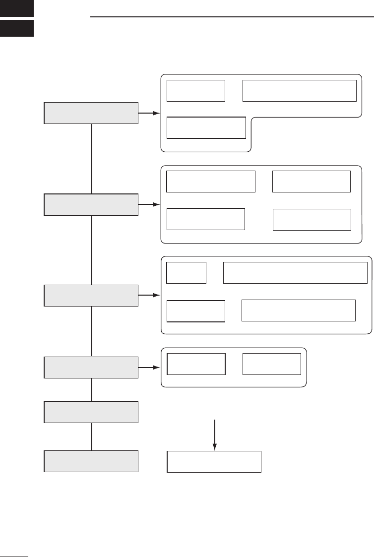
SETTING SCREEN CONFIGURATION MAP
13
72
The figure below illustrates the configuration of the setting screen.
[Wireless LAN Settings]
screen
Wireless LAN
Settings MAC Address Security Settings
Static Routing Settings
Network Interface List
Routing Mode Settings
DHCP Server Settings
Manager ID
Settings SYSLOG
Settings
AP-3 IP Address
Settings
SL-1100 or SL-1105
Advanced Settings
[AP-3 Network Settings]
screen
[Routing Settings] screen
[AP-3 Management
Settings] screen
RIP
Settings
IP Routing
Information
[Save Settings] screen
[Initialize Settings] screen [Setting Initialization Mode]
screen
(☞P47)
(☞P51)
(☞P55)
(☞P58)
(☞P60)
(☞P65)
(☞P47)
(☞P47)
(☞P51)
(☞P55)
(☞P55)
(☞P58) (☞P59)
(☞P57)
(☞P55)
(☞P51)
(☞P52)
(☞P50)
Start up in
[Setting Initialization Mode]
(☞P63)
Static DHCP
Server Settings
(☞P54)

REFERENCE INFORMATION 14
73
14-1 Default Setting Values
[Wireless LAN Settings] screen
Wireless LAN Settings
• ESS ID: LG (alphanumeric characters, upper
case)
SL-1100 Advanced Settings
SL-1100 Settings
• Channel: 11
• Security level: None
MAC Address Security Setting
• Use MAC Address Security: No
[AP-3 Network Settings] screen
Routing Mode Setting
• Use Routing Mode: No
AP-3 IP Address Settings
Wired LAN
• IP Address: 192.168.0.1
• Subnet Mask: 255.255.255.0
Wireless LAN
• IP Address: 192.168.1.1
• Subnet Mask: 255.255.255.0
DHCP Server Settings
• Use DHCP Server Function: Yes
• Lease Time: 3 days
Wired LAN
• Initial Allocation IP Address: 192.168.0.10
• Subnet mask: 225.225.225.0
• Number of Allocations : 30
Wireless LAN
• Initial Allocation IP Address: 192.168.1.10
• Subnet mask: 225.225.225.0
• Number of Allocations: 30
[Routing Settings] screen
RIP Setting
• Use RIP: Yes
[AP-3 Management Settings] screen
SYSLOG Settings
• Use DEBUG: Yes
• Use INFO: Yes
• Use NOTICE: No
• Facility: 1
14-2 Function List
• Wireless access point function
• Wireless roaming function
• Wireless security
(ESS ID, MAC address, WEP)
• Routing protocol
TCP/IP (RIP static)
• DHCP server function
• DHCP static function
• Supports SYSLOG
• Remote setup (web browser)
• Firmware Update
14-3 [ETHERNET] Port
12345678
One RJ-45 modular jack (8-pin)
1. Send (+)
2. Send (–)
3. Receive (+)
4. Not used
5. Not used
6. Receive (–)
7. Not used
8. Not used
The original factory setting values are listed below for each setting screen of the
AP-3 unit.
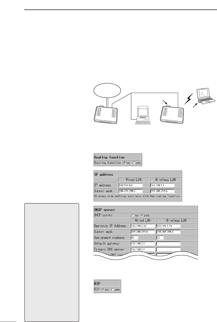
REFERENCE INFORMATION
14
74
14-4 Basic Setting Example
This section presents some of the setting values
entered when the AP-3 unit is used in the network
configuration illustrated below.
For setting items not shown here, enter values that
are appropriate for the particular network configura-
tion.
[DR-1 WL:
Required Settings]
• Use DHCP server
function.
• DR-1WL IP address:
192.168.0.1
Internet
Wireless terminal
Wired terminal
SL-1100
SL-1100
AP-3
DR-1WL
■Using the same subnet for both the wired and wireless LAN
[AP-3:
Required Settings]
• Use DHCP server
function.
• AP-3 IP address:
192.168.0.2
• Initial allocation IP
address: 192.168.0.50
• Do not use routing
mode.
[Setting Tips]
Only change the values in
the "Wired LAN" column of
the [DHCP Server Settings]
screen.
Set the initial allocation IP
address so that the range of
IP addresses over which the
AP-3 can allocate does not
overlap the range of IP
addresses over which the
DR-1WL (router) can allo-
cate.
Set the [Default Gateway]
and the [Primary DNS
Server] to the same value as
the IP address of the DR-
1WL.
Although the [RIP Setting]
does not have a direct influ-
ence on the performance of
the network, unnecessary
traffic can be avoided by not
using RIP.
[AP-3 Network Settings] screen
[Routing Setting] screen
* The wired terminal will obtain an IP address from either
the DR-1WL or the AP-3.
* The wireless terminal will obtain an IP address from the
AP-3.
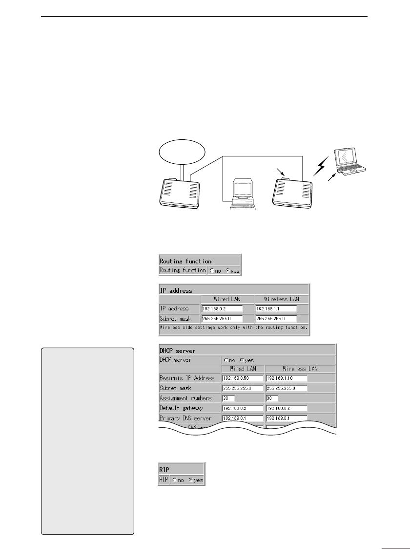
REFERENCE INFORMATION 14
75
14-5 Practical Setting Example
This section presents some of the setting values
entered when the AP-3 unit is used in the network
configuration illustrated below.
For setting items not shown here, enter values that
are appropriate for the particular network configura-
tion.
[DR-1 WL:
Required Settings]
• Use DHCP server func-
tion.
• DR-1WL IP address:
192.168.0.1
• Use RIP on the LAN
side.
• Use substitute response
function of DNS server.
Internet
Wireless terminal
Wired terminal
SL-1100
SL-1100
AP-3
DR-1WL
■Using the different subnets for the wired LAN and the wireless LAN
[AP-3:
Required Settings]
• Use DHCP server func-
tion.
• AP-3 IP address:
192.168.0.2
• Initial allocation IP
address: 192.168.0.50
• Use RIP.
• Use routing mode.
[Setting Tips]
Change the values in both
the "Wired LAN" and
"Wireless LAN" columns of
the [DHCP Server Settings]
screen.
Set the initial allocation IP
address so that the range of
IP addresses over which the
AP-3 can allocate does not
overlap the range of IP
addresses over which the
DR-1WL (router) can allo-
cate.
Set the [Default Gateway] to
the same value as the IP
address of the AP-3 unit.
Set the [Primary DNS
Server] to the same value as
the IP address of the DR-
1WL.
[AP-3 Network Settings] screen
[Routing Setting] screen
* The wired terminal will obtain an IP address from either
the DR-1WL or the AP-3.
* The wireless terminal will obtain an IP address from the
AP-3.
* The routing information created using RIP is displayed
on the [IP Routing Information] screen.
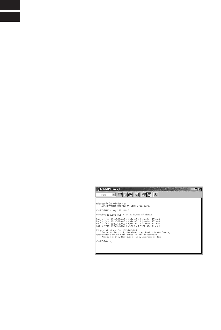
MAINTENANCE
15
76
■Checking the connection with the AP-3
If the IP address of each station (terminal group) is
set correctly, you can easily test whether or not IP
packets are reaching their proper destination by
using the “ping” command.
To conduct the test, open the MS-DOS window and enter
the following command:
ping xxx.xxx.xxx.xxx
where “xxx.xxx.xxx.xxx” is the IP address of the AP-
3 unit.
By executing the ping command, four pings (echo
requests) are transmitted and a reply message should be
received for each ping. If a reply is not received, check
the protocol settings of the station and the AP-3 unit, as
well as the settings of the respective wireless LAN cards
(Network Mode, ESS ID, etc.).
The message “destination unreachable” will be displayed
if the IP address and subnet mask of the station and AP-
3 unit are not set correctly.
●[Example of ping command execution] (normal case)
Windows 98

AFTER SERVICE 16
77
• Warranty
At the time of purchase, the retailer will provide a warranty sheet complete
with the details of the purchase (date of purchase, name of local dealer,
etc.). Make sure the information is correct and keep the warranty in a safe
place for future use.
• Requesting servicing
Refer to the instruction manual and check the settings of both the comput-
er and the AP-3 unit. If you cannot solve the problem, request servicing
according to the following terms:
Contact the local dealer where you purchased the product.
The retailer will service the product in accordance with the warranty. Have
your warranty ready at the time of request.
Contact the local dealer where you purchased the product.
If the product is serviceable, the retailer will repair the product for a fee.
• Questions Regarding Service
If you have any questions regarding service, contact the local dealer where
you purchased the product or contact the service staff at one of our sales
offices.
AAfftteerr tthhee wwaarrrraannttyy ppeerriioodd
DDuurriinngg tthhee wwaarrrraannttyy ppeerriioodd
■When the unit fails

SPECIFICATION
17
78
• LAN interface : Ethernet port–RJ-45 Type modular jack
*Polarity inversion switch is equipped.
IEEE802.3/10 BASE-T equivalent
IEEE802.3u/100 BASE-TX equivalent
: Insert ICOM LAN card to the PCMCIA slot
PCMCIS Type II equivalent (3.3 V acceptable)
• Transmission speed : Ethernet port–10/100 Mbps auto select
Wireless LAN–11 Mbps (Max.)*
*When SL-1100/1105 is connected.
• Rooting Type : Static/Dynamic(RIP)
• Interface : POWER, LAN and Wireless LAN LED
■Applicable LAN card
• SL-1100 and SL-1105
• Power supply requirement : 12 V DC (11 to 16 V DC • negative ground)
• Current drain : Max. 600 mA
• Dimensions (projections not : 230 (W) x 38 (H) x 167 (D) mm; 91/16 (W) x 11/2(H) x
included) 69/16 (D) in
• Weight : Approx. 650 g; 2215/16 oz
• Usable temperature range : 0°C to +40°C; +32°F to +104°F
■Wired

SPECIFICATION17
79
■LAN card (SL-1100 and SL-1105)
• Wireless Medium : Direct Sequence Spread Spectrum (DSSS)
• Network Standard : Based on IEEE 802.11b
• Frequency Band : 2400 – 2483.5 MHz
• Number of channels : 11
• Modulation : DBPSK at 1 Mbps
DQPSK at 2 Mbps
CCK at 5.5 and 11 Mbps
• Encryption : 64-bit or 128-bit WEP
• Output Power : ±20 mW
• Frequency Stability : 20 ppm (0°C to +50°C; +32°F to +122°F)
• Antenna : Dual pattern antenna with diversity support
• Sensitivity : More than –76 dBm (FER 8% at 1024 octets data)
• Power supply requirement : (SL-1100) 5 V DC ±5% (negative ground)
(SL-1105) 3 V DC ±5% (negative ground)
• Current drain : Transmit 290 mA
Receive 210 mA
• Usable temperature range : 0°C to +50°C; +32°F to +122°F
• Dimensions (projections not :
included)
• Weight : Approx. 40 g; 14 oz
• Approval standard : FCC Part 15, Sub Part B, Class B, Part 15.247
• Media Access Protocol : Carrier Sense Multiple Access with Collision
Avoidance (CSMA/CA)
• Host interface : PCMCIA Type II slot
• Network operating system : Microsoft® Windows® 2000/NT/98/95

GLOSSARY
18
80
DHCP server
DHCP (Dynamic Host Configuration Protocol) is a
protocol that allows a client in a TCP/IP network to
automatically obtain required information from a
server.
The DHCP server manages such network infor-
mation as the IP Address, Default Gateway, and
Domain Name.
The AP-3 is provided with a DHCP server that allo-
cates an IP address, default gateway, DNS
address, etc., to the DHCP clients (computers)
when the DHCP clients start up.
DNS (Domain Name System)
DNS is a name resolution service for TCP/IP net-
works.
The AP-3 provides a domain name service, in
accordance with DNS, that allows computer
names and domain names to be registered in a
domain name server.
By using the domain name service, the IP address
of the desired site can be designated not as num-
bers but as easy-to-understand domain names
and host names.
ESS ID
An ESS ID is a name used for identification when
multiple network groups are formed within the
transmission area of a wireless network. The ESS
IDs of the wireless terminals in a wireless network
group communicating with the AP-3 are set to the
same value as the ESS ID of the AP-3.
ETHERNET
Ethernet is a set of standards and protocols for
LAN communications developed by Xerox, Digital
Equipment Corporation, and Intel. Types of
Ethernet include 10BASE-T, 10BASE-5, and
10BASE-2, each requiring a different cable speci-
fication.
IP (Internet Protocol) address
The IP address is a 32-bit address used to distin-
guish the devices in a network constructed using
TCP/IP protocol. Each network device has a
unique IP address.
The IP address is usually expressed as a base-10
numeral string made up of four 8-bit sections
(Example: 192.168.0.1).
A private IP address is an IP address set indepen-
dently by the network manager. It is not necessary
to petition an address management institution or a
provider, but a private IP address must be allocat-
ed according to the following rule: When connect-
ing with an external network, the private address
must be converted into a global IP address.
The following IP addresses can be used freely as
private IP adresses:
Class A: 10.0.0.0 to 10.255.255.255
Class B: 172.16.0.0 to 172.31.255.255
Class C: 192.168.0.0 to 192.168.255.255
LAN (Local Area Network)
A network that is relatively small in scale. A typical
LAN occupies a single office or a single floor of a
building.
MAC address (Media Access Control Address)
A MAC address is a physical address (number)
uniquely set into each wired or wireless LAN card.
LAN card manufacturers manage MAC addresses
so that no two LAN cards in the world have the
same MAC address. Ethernet uses the MAC
address to send and receive frames.
RIP (Routing Information Protocol)
RIP is a protocol used in a TCP/IP network to
exchange routing information between routers.
Routers use RIP to send packets to the correct
destination.
SYSLOG
SYSLOG is a function for sending system mes-
sages to destinations within a network.
Log information can be managed using a UNIX or
other SYSLOG server if the network supports this
function.
TCP/IP
TCP/IP is the basic protocol of the internet and is
currently the most popular protocol in the world. It
is supported by Windows 95/98, Windows NT, and
the other major operating systems.
SMTP and FTP use this protocol.
A TCP/IP control panel is a standard item in
Macintosh computers provided with Open
Transport.
URL (Uniform Resource Locator)
URLs are used to access home pages and other
sites on the internet.
Our URL is http://www.icom.co.jp.
Web browser
A web browser is a software application used for
searching web servers and viewing web pages.
Common applications include Internet Explorer
and Netscape Navigator.

GLOSSARY 18
81
10BASE-T and 100BASE-TX
10BASE-T and 100BASE-TX are connection
specifications for Ethernet configurations using
twisted pair cable.
The "10" in 10BASE-T represents an Ethernet
transmission speed of 10 Mbps and the "T" repre-
sents twisted pair cable.
Category 5 twisted pair cable supports 100BASE-
TX as well as 10BASE-T.
Access point
An access point is any device used to connect a
wired LAN to a wireless LAN.
Client
A client is any terminal or application in a network
that requests information or a service from a serv-
er and receives the corresponding response.
Global IP address
A global address is a globally unique address that
held by only one device on the entire internet.
Subnet mask
A subnet mask is used to allow on IP address rep-
resent both the network address and the host
address.
Assuming the IP address of a certain host is
192.168.0.1 and the subnet mask is
255.255.255.0, if the IP address and subnet mask
are multiplied as binary numbers the network
address will be 192.168.0.0 and the remaining 1
will be the host address.
Traffic
Traffic refers to the flow of packets over a network
or the load (amount of data) born by the network
circuits. When the traffic is high, data transfers
may be delayed and data may be lost.
Network
An arrangement wherein servers, work stations,
computers, and other devices are connected via
cable or a telephone circuit for the purpose of
exchanging data.
Packet
The unit by which data is send and received in a
network. A packet comprises a header portion con-
taining information required for sending and
receiving and a data portion containing the data
being sent.
Password
A character string that a user must enter in order
to access a network. The password provides net-
work security because, once established, the
password must be entered correctly by the user or
access will be denied.
Hub
A hub is required when the AP-3 and other devices
are used construct a network.
The hub is connected to the AP-3 using 10BASE-
T or 100BASE-TX cable.
In order to achieve transmission speeds of 100
Mbps, Category 5 twisted pair cable must be used
and the hub must support 100BASE-TX.
Flash memory
The flash memory is a memory device in the AP-3
to which data can be written. Information stored in
the flash memory is not erased when the power to
the unit is turned off.
Protocol
A protocol is a defined set of steps that is followed
when data is sent and received.

A-5681H-1EX ©2000 Icom Inc.
Count on us!
1-1-32, Kamihigashi, hirano-ku, Osaka 547-0003, Japan