ICOM orporated IC-2800H Receiver Portion of Amateur Transceiver User Manual IC 2800 IM 1
ICOM Incorporated Receiver Portion of Amateur Transceiver IC 2800 IM 1
UserManual.wiki
>
ICOM orporated
>
IC 2800H User Manual
manual
Navigation menu
Upload a User Manual
Namespaces
Wiki Guide
HTML
PDF
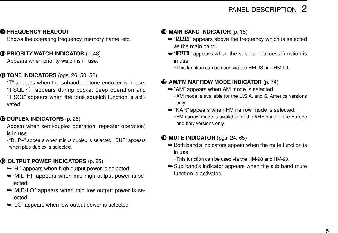
Info
Views
User Manual
Discussion / Help
Navigation
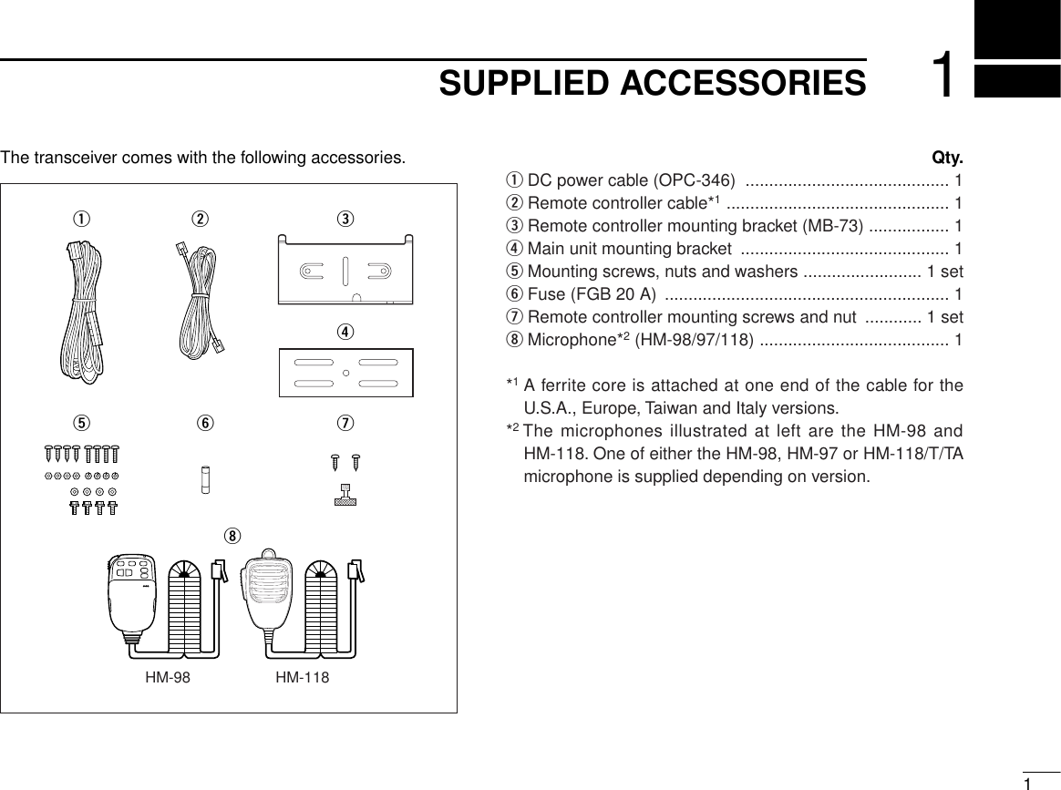
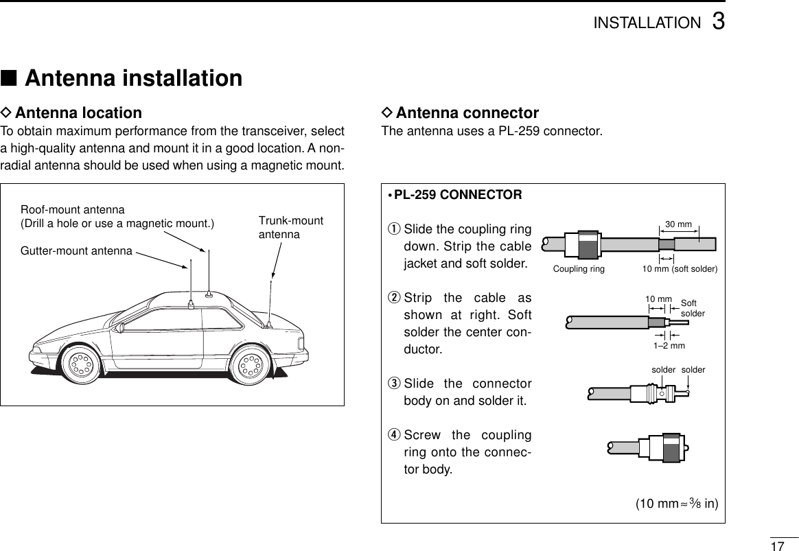
![1 SUPPLIED ACCESSORIES ......... 12 PANEL DESCRIPTION ......... 2–13■Controller unit ......................... 2■Function display ...................... 4■Basic function menu ............... 6■Main unit ................................. 8■HM-98 microphone ............... 10■HM-97/118 microphone ........ 133 INSTALLATION ................... 14–17■Location ................................ 14■Mounting with the mountingbracket .................................. 14■Mounting the remote controller ............................... 15■Battery connection ................ 15■DC power supply connection ............................ 16■Cable connection .................. 16■Antenna installation .............. 174 FREQUENCY SETTING ...... 18–22■Preparation ........................... 18■Lock functions ....................... 19■Using the tuning dial ............. 20■Using the [Y]/[Z] keys .......... 20■Setting a tuning step ............. 21■Using the keypad .................. 225 BASIC OPERATION ............ 23– 25■Receiving .............................. 23■Monitor function .................... 24■Audio mute function .............. 24■Transmitting .......................... 24■Selecting output power ......... 25■One-touch PTT function ....... 256 REPEATER OPERATION .... 26–31■Accessing a repeater ............ 26■1750 Hz tone ........................ 28■Subaudible tone .................... 29■Offset frequency ................... 30■Auto repeater function .......... 317 MEMORY/CALL CHANNELS ......................... 32–39■General ................................. 32■Programming during selection................................. 32■Programming after selection.. 33■Transferring memory contents to another memory ............... 33■Programming during selectionvia the microphone ............... 34■Programming after selection via the microphone ............... 34■Transferring memory contents to another memory via themicrophone ........................... 35■Memory clear ........................ 36■Alphanumeric display ............ 37■Call channel .......................... 388 SCRATCH PAD MEMORY ... 40–41■What is a scratch pad memory? ............................... 40■Calling up a scratch pad memory ................................. 40■Transferring scratch pad memory contents .................. 419 SCAN OPERATION ............. 42–46■Scan types ............................ 42■Full/programmed scan .......... 43■Selecting scan edges ........... 44■Memory scan ........................ 45■Skip channel setting ............. 46■Scan resume condition ......... 4610 BAND SCOPE ............................ 47■Operation .............................. 4711 PRIORITY WATCH .............. 48–49■Priority watch types .............. 48■Priority watch operation ........ 4812 SUBAUDIBLE TONE OPERATION ........................ 50–53■Tone squelch operation ......... 50■Pocket beep operation .......... 52■Tone scan ............................. 5313 DTMF MEMORY .................. 54–56■Programming a DTMF code .. 54■Transmitting a DTMF code..... 55■DTMF speed ......................... 5614 WIRELESS OPERATION .... 57–62■Connection ........................... 57■HM-90 wireless microphone .. 57■EX-1759 installation .............. 58■HM-90 switches .................... 59■Microphone address ............. 6215 OTHER FUNCTIONS .......... 63–75■Beep tones ........................... 63■Time-out timer ....................... 63■Auto power-off function ......... 64■Cooling fan ............................ 64■Squelch delay ....................... 65■Sub band mute ..................... 65■Sub band busy beep ............. 66■Automatic RF attenuator ....... 66■Memory name indication ...... 67■HM-98 [F-1]/[F-2] keys .......... 67■HM-97/118 [UP]/[DN] keys .... 68■Display contrast .................... 68■Display brightness ................ 69■Indication type ...................... 69■My call function ..................... 69■Packet operation ................... 70■Video monitor function .......... 73■Demonstration display .......... 74■AM/FM narrow mode ............ 74■Fuse replacement ................. 74■Partial reset .......................... 75■All reset ................................. 7516 CS-2800 CLONING SOFTWARE ......................... 76–7917 TROUBLESHOOTING ............... 8018 OPTIONS .................................... 8119 SPECIFICATIONS ............... 82–83iiiTABLE OF CONTENTS](https://usermanual.wiki/ICOM-orporated/IC-2800H/User-Guide-23181-Page-4.png)
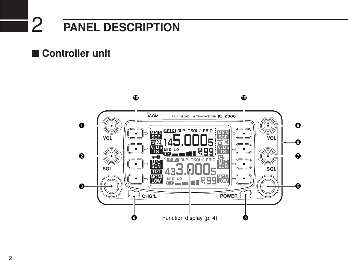
![32PANEL DESCRIPTIONqVHF VOLUME CONTROL [VOL]Adjusts the VHF audio level. (p. 23)wVHF SQUELCH CONTROL [SQL]➥Adjusts the VHF squelch level. (p. 23)➥Depending on the set mode setting, the RF attenuatoris automatically activated when [SQL] is rotated clock-wise past the 12 o’clock position. (pgs. 23, 66)eVHF TUNING DIAL [DIAL]Rotate [DIAL] to set operating frequencies, memory chan-nels, set mode contents, etc. (p. 20)rCHANGE/LOCK SWITCH [CHG/L]➥Toggles the multi-function switch menu. (p. 6)➥Push [CHG/L] for 2 sec. to toggle the lock function ONand OFF. (p. 19)tPOWER SWITCH [POWER]Push for 2 sec. to toggle the transceiver power ON andOFF. (p. 18)yUHF TUNING DIAL [DIAL]Rotate [DIAL] to set operating frequencies, memory chan-nels, set mode contents, etc. (p. 20)uUHF SQUELCH CONTROL [SQL]➥Adjusts the UHF squelch level. (p. 23)➥Depending on the set mode setting, the RF attenuatoris automatically activated when [SQL] is rotated clock-wise past the 12 o’clock position. (pgs. 23, 66)iVIDEO INPUT JACK [VIDEO IN]Inputs an NTSC or PAL video signal depending on version.(p. 73)oUHF VOLUME CONTROL [VOL]Adjusts the UHF audio level. (p. 23)!0 MULTI-FUNCTION SWITCHES (pgs. 6, 7)Push to select the function indicated in the right-hand orleft-hand LCD display of these switches.•Left-hand switches are used for VHF band and right-handswitches are used for UHF band.•Functions vary depending on the operating condition.](https://usermanual.wiki/ICOM-orporated/IC-2800H/User-Guide-23181-Page-7.png)
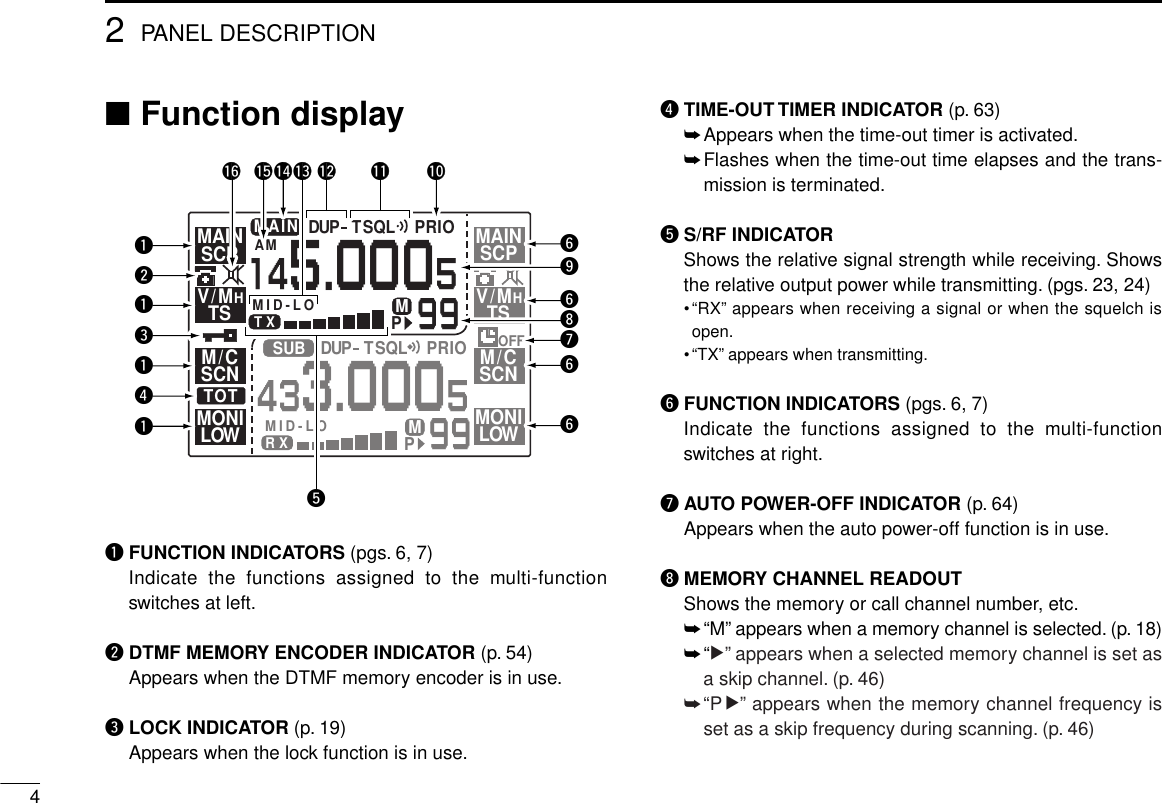
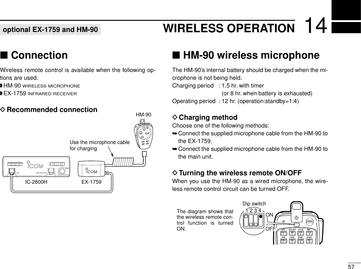
![62PANEL DESCRIPTION■Basic function menuThe multi-function switches have 2 main menus. Pushing[CHG/L] toggles between the 2 multi-function switch menus.Left-hand switches are used for VHF band and right-handswitches are used for UHF band except iand o.MAINSCPMAINSCPV/MHTSV/MHTSM/CSCNM/CSCNMONILOWMONILOWMID-LOMID-LOMAIN433.00012145.00012MID-LOMID-LOMAIN433.00012145.00012MAINEDIT EDITMAINS.MWMW S.MWMWDTMFTONDUP TONDUPDISPSETCHG/LqwerrewqtyuiouytqMAIN BAND/BAND SCOPE MENU [MAIN(SCP)]➥Push to select the main band. (p. 18)➥Push for 2 sec. to enter the band scope screen. (p. 47)wVFO/MHz/TUNING STEP MENU [V/MH(TS)]➥Push to select VFO mode or to select the MHz tuningstep while in VFO mode. (p. 20)➥Push for 2 sec. to enter tuning step screen. (p. 21)eMEMORY CHANNEL/CALL CHANNEL/SCAN MENU[M/C(SCN)]➥Push to select the memory mode or call channel. (pgs.18, 38)➥Push for 2 sec. to enter the scan screen. (p. 42)](https://usermanual.wiki/ICOM-orporated/IC-2800H/User-Guide-23181-Page-10.png)
![72PANEL DESCRIPTIONrMONITOR/LOW POWER MENU [MONI(LOW)]➥Push to toggle the monitor function ON and OFF. (p. 24)➥Push for 2 sec. to change the output power selection. (p.25)•Low (LO), mid-low (MID-LO), mid-high (MID-HI) and high (HI)powers are available.tMAIN BAND/MEMORY EDIT MENU [MAIN(EDIT)]➥Push to select the main band. (p. 18)➥Push for 2 sec. to enter the edit screen. (pgs. 29, 30, 37,46, 51)yTONE/DUPLEX MENU [TON(DUP)]➥Push to activate the following functions in order.•Subaudible tone encoder—“T” appears. (p. 26)•Pocket beep—“T SQLì” appears. (p. 52)•Tone squelch—“T SQL” appears. (p. 50)•No tone operation—no indicator appears.➥Push for 2 sec. to select semi-duplex or simplex opera-tion. (p. 26)•“DUP–” appears during minus duplex operation, “DUP” ap-pears during plus duplex operation and no indicator appearsduring simplex operation.uSELECT MEMORY WRITE/MEMORY WRITE MENU[S.MW(MW)]➥Push to select the desired memory channel number tobe programmed. (p. 32)➥Push for 2 sec. to program a memory channel or callchannel while in VFO mode. (p. 32)➥Push for 2 sec. to transfer a memory channel, call chan-nel or scratch pad memory contents into the VFO whennot in VFO mode. (p. 33)iDTMF MENU [DTMF]➥Push to toggle the DTMF memory ON and OFF. (p. 55)➥Push for 2 sec. to enter the DTMF memory screen. (p.54)oDISPLAY/SET MODE MENU [DISP(SET)]➥Push to enter the display set mode screen. (p. 68)➥Push for 2 sec. to enter the set mode screen.](https://usermanual.wiki/ICOM-orporated/IC-2800H/User-Guide-23181-Page-11.png)
![82PANEL DESCRIPTION■Main unitqMICROPHONE CONNECTOR [MIC]Connects the supplied microphone.wCONTROLLER CONNECTOR [CONTROLLER] (p. 16)Connects the controller unit with the supplied cable.eDATA CONNECTOR [DATA] (p. 70)Connects a TNC (Terminal Node Controller), etc. for datacommunications.•See the information at right for details.r144 MHz SPEAKER CONNECTOR [144 MHz SP]Connects an 8 Ωspeaker, if desired.t430(440) MHz SPEAKER CONNECTOR [430(440) MHz SP]Connects an 8 Ωspeaker, if desired.DATAMIC CONTROLLERqwetryuq+8 V DC output (Max. 10 mA)wFrequency up/downeHM-90/98 control inputrPTTtMicrophone groundyMicrophone inputuGroundiNo connection➀➇With no exter-nal speakers[144MHz SP]only[430(440) MHzSP] only2 externalspeakersVHF band audio UHF band audioConnectedspeakerInternal speaker (mixed audio)External speaker (mixed audio)Internal speakerExternal speaker via[144MHz SP]External speaker via[430(440) MHz SP]External speaker](https://usermanual.wiki/ICOM-orporated/IC-2800H/User-Guide-23181-Page-12.png)
![yPOWER RECEPTACLE [DC13.8V] (pgs. 15, 16)Accepts 13.8 V DC ±15% with the supplied DC powercable.•Current of 12 A or greater is required.DO NOT use a cigarette lighter socket as a powersource when operating in a vehicle.The plug may causevoltage drops and ignition noise may be superimposedonto transmit or receive audio.uANTENNA CONNECTOR [ANT]Connects a 50 Ωantenna with a PL-259 connector and a50 Ωcoaxial cable.DDATA JACK PIN ASSIGNMENTSqDATA INInput terminal for data transmit. See p. 70 for details onhow to toggle data speed between 1200 and 9600 bps.wGNDCommon ground for DATA IN, DATA OUT and AF OUT.ePTTPPTT terminal for packet operation only. Connect ground totransmit data.rDATA OUTData out terminal for 9600 bps operation only.tAF OUTData out terminal for 1200 bps operation only.yPSQL (squelch out)Becomes high (+5V) when the transceiver receives a sig-nal which opens the squelch.•To avoid unnecessary TNC transmission, connect squelch to theTNC to inhibit transmission when receiving signals.•Keep audio output at a normal level, otherwise a “PSQL” signalwill not be output.92PANEL DESCRIPTIONqDATA IN (1200 bps: AFSK9600 bps: G3RUH, GMSK)wGNDePTTPrDATA OUT (9600 bps)tAF OUT (1200 bps)yPSQLANTENNA INFORMATIONFor radio communications, the antenna is of critical impor-tance, along with output power and sensitivity. The trans-ceiver accepts a 50 Ωantenna and less than 1.5 : 1 ofVoltage Standing Wave Ratio (VSWR). High SWR valuesnot only may damage the transceiver but also lead to TVI orBCI problems.](https://usermanual.wiki/ICOM-orporated/IC-2800H/User-Guide-23181-Page-13.png)
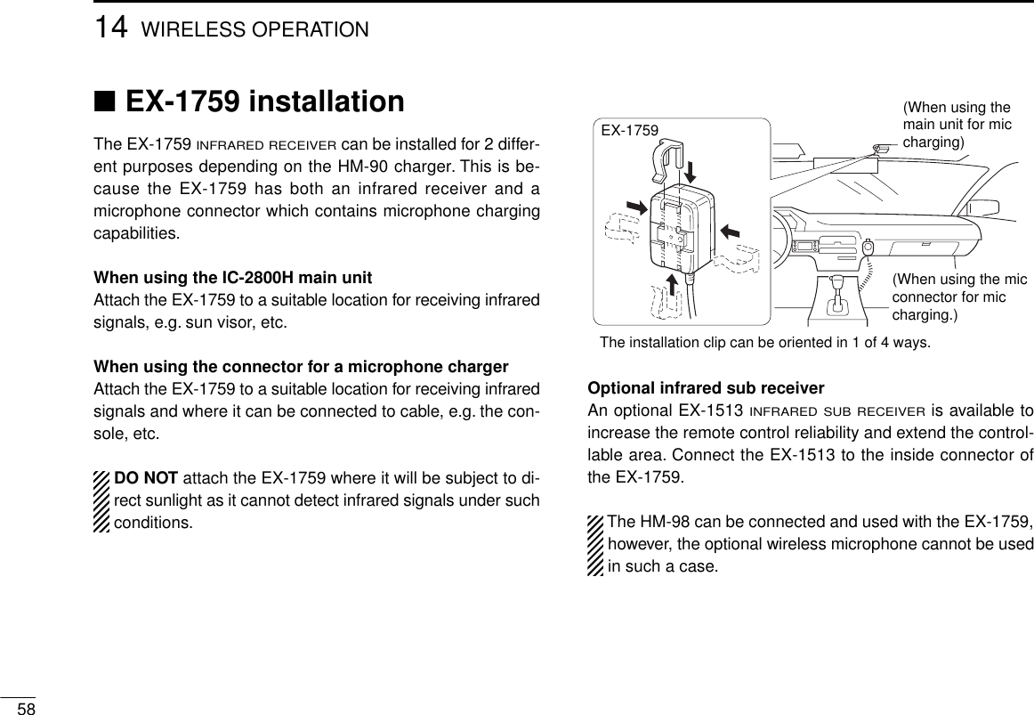
![■HM-98 microphone*qUP/DOWN SWITCHES [YY]/[ZZ]➥Push either switch to change the operating frequency,memory channel, set mode contents, etc. (p. 20)➥Push either switch for 2 sec. to start scanning. (p. 43)wPTT SWITCH➥Push and hold to transmit; release to receive. (p. 24)➥Toggles between transmitting and receiving while theone-touch PTT function is in use. (p. 25)eVFO SWITCH [VFO(LOCK)]➥Push to select VFO mode. (p. 18)➥Push for 2 sec. to toggle the lock function. (p. 19)rMEMORY SWITCH [MR(CALL)]➥Push to select memory mode.➥Push for 2 sec. to select the call channel. (p. 38)tACTIVITY INDICATORLights red while a key is pushed; lights green while theone-touch PTT function is in use.yBAND SWITCH [BAND(SUB)] (p.18)➥Push to toggle the operating band or set the sub bandas the main band.➥Push for 2 sec. to toggle the sub band access function.uFUNCTION SWITCHES [F-1]/[F-2] (p.67)Assign your desired key function from the front panelswitches.•Default settings are [VHF M/C] for [F-1] and [UHF M/C] for [F-2].iFUNCTION INDICATOR➥Lights orange while [FUNC] is activated—indicates thesecondary function of switches can be accessed.➥Lights green when [DTMF-S] is activated—DTMF sig-nals can be transmitted with the keypad. (p. 55)oKEYPADUsed for controlling the transceiver, transmitting DTMF sig-nals, etc. See the following 2 pages for details.102PANEL DESCRIPTIONLOCKVFOCALLMRSUBBANDMWFUNCACLRD-OFFBSETPTT-M3PRIODTMF6LOWAFC-OFF2SCANCSQL5MIDAFC1MONIPGR4HIGHT-OFFCENTTSQL9SIMP16KEY LOCK#TSQLS8DUP+TONE-20TONE7DUP–TONE-1F-2F-1DTMF-SMUTEDSQLSQLVOLVOLMic elementqwer tyuio*Some versions aresupplied with theHM-97/118 instead.](https://usermanual.wiki/ICOM-orporated/IC-2800H/User-Guide-23181-Page-14.png)
![112PANEL DESCRIPTIONKEY FUNCTION SECONDARY FUNCTION (after )FUNCOTHER FUNCTIONSAFC1MONIToggles between opening and closing theoperating band’s squelch. (p. 24) No secondary function.After :Transmit the appropriateDTMF code or push [0]to [9], [A] to [D] to trans-mit the DTMF memorycontents when theDTMF memory encoderis activated. (p. 54)DTMF-SAFC-OFF2SCANStarts and stops scanning. (p. 42) No secondary function.PTT-M3PRIO Starts and stops priority watch. (p. 48) Turns the one-touch PTT function ON andOFF. (p. 25)PGR4HIGH Selects high output power. (p. 25) No secondary function.CSQL5MID Selects mid-high output power. (p. 25) No secondary function.DTMF6LOW Selects low output power. (p. 25) Turns the DTMF memory encoder functionON. (p. 54)TONE7DUP– Selects –duplex. (p. 27) Turns the subaudible tone encoder ON.(p. 27)TSQLS8DUP+ Selects +duplex. (p. 27) Turns the pocket beep function ON. (p. 52)TSQL9SIMP Selects simplex. (p. 27) Turns the tone squelch function ON. (p. 50)TONE-20VOLIncreases the audio output. (p. 23)•The [VOL] controls on the controller unit havepriority when rotated.While being pushed, transmits a 1750 Hztone. (p. 28)](https://usermanual.wiki/ICOM-orporated/IC-2800H/User-Guide-23181-Page-15.png)
![122PANEL DESCRIPTIONKEY FUNCTION SECONDARY FUNCTION (after )FUNCOTHER FUNCTIONSMWACLR•Clears a digit before entry. (p. 22)•Cancels the monitor, scan, priority watch,DTMF memory, mute function or setmode condition. (pgs. 24, 42, 48, 54)•Writes the VFO contents into the memorychannel or call channel. (pgs. 34, 39)•Advances the memory channel numberwhen continuously pushed after program-ming is completed. (p. 34) After :Transmit the appropriateDTMF code or push [0]to [9], [A] to [D] to trans-mit the DTMF memorycontents when theDTMF memory encoderis activated. (p. 54)DTMF-SD-OFFBSETEnters set mode and decreases the setmode selection order. DTMF memory OFF.16KEY LOCK#SQLT-OFFCENT•Sets the keypad for numeral input.(p. 22)•Advances the set mode selection orderafter entering set mode.Turns the subaudible tone encoder, pocketbeep or tone squelch OFF. (pgs. 27, 50, 52)Decreases the squelch level. (p. 23)•The [SQL] controls on the controller unit havepriority when rotated.MUTEDSQLIncreases the squelch level. (p. 23)•The [SQL] controls on the controller unit havepriority when rotated.Mutes both band’s audio. (p. 24)•Mute function is released when any operation isperformed.Locks the digit keys on the keypad (includingthe A–D, # and Mkeys). (p. 19)TONE-1MVOLDecreases the audio output. (p. 23)•The [VOL] controls on the controller unit havepriority when rotated.Sends a 1750 Hz tone signal for 0.5 sec.(p. 28)After :Transmit the appropriateDTMF code. (p. 54)DTMF](https://usermanual.wiki/ICOM-orporated/IC-2800H/User-Guide-23181-Page-16.png)
![132PANEL DESCRIPTION■HM-97/118 microphoneqPTT SWITCHPush and hold to transmit; release to receive. (p. 24)wUP/DOWN SWITCHES [UP]/[DN]➥Push either switch to change the operating frequency,memory channel, set mode contents, etc. (p. 20)➥Push either switch for 2 sec. to start scanning. (p. 42)➥Activate a function programmed in set mode. (p. 68)eLOCK SWITCHLocks the [UP]/[DN] keys on the microphone.rTONE SWITCH (HM-97 only)Push to transmit a 1750 Hz tone call signal. (p. 28)tDTMF KEYPAD (HM-118T/TA only)Used for transmitting DTMF signals.1 2 3 A4 5 6 B7 8 9 C0 DHM-97HM-118HM-118T/TAONOFFqweert](https://usermanual.wiki/ICOM-orporated/IC-2800H/User-Guide-23181-Page-17.png)
![184FREQUENCY SETTING■PreparationDTurning power ON/OFFBefore operating the transceiver for the first time it’s a goodidea to reset the transceiver’s CPU.This will ensure that alltransceiver settings are at their defaults. See p. 75 for CPUresetting details.➥Push [POWER] for 2 sec. to turn power ON or OFF.DOperating bandThe transceiver can receive 144 MHz and 430(440) MHzband signals simultaneously. To activate all functions or tochange frequency via the microphone, you must designateone band as the main band. The transceiver can transmit asignal on the main band only.➥Push either [MAIN] to select the desired transmit band.•“Q” indicator shows the selected band as the main band.➥Push [BAND] to select the desired operatingband.•“Q” indicator shows the selected band as themain band.DVFO and memory modesThe transceiver has 2 basic operating modes: VFO mode andmemory mode. Select VFO mode first to set an operating fre-quency.➥Push [V/MH] to select VFO mode when the transceiver isnot in VFO mode.•If VFO mode is already selected,the digits below 100* kHz disap-pear. In this case, push [V/MH]again (or push twice or 3 times de-pending on version).*The digits below 1 or 10 MHz dis-appear for some versions.➥Push [VFO] to select VFO mode.➥Push [MR] to select memory mode.VFOBANDNote that in this manual, sections beginning witha microphone icon (as above), designate opera-tion via the HM-98 microphone.[POWER][MAIN][MAIN]MAINSCPMAINSCPV/MHTSV/MHTSMID-LOMAINM12145.000“M” appears in memory mode.](https://usermanual.wiki/ICOM-orporated/IC-2800H/User-Guide-23181-Page-22.png)
![■Lock functionsTo prevent accidental frequency changes and unnecessaryfunction access, use the lock function. The transceiver andHM-98 have 2 different lock functions.DFrequency lockThis function locks the tuning dials and switches electronicallyand also locks the microphone switches.➥Push [CHG/L] for 2 sec. to toggle the frequency lock func-tion ON and OFF.•[CHG/L], [MAIN], [MONI], [VOL], [SQL], [PTT] and [BAND] canbe used while the frequency lock function is in use. Also,TONE-1, TONE-2, DTMF tones or DTMF memory contents canbe transmitted from the HM-98 microphone.➥Push [(VFO)LOCK] for 2 sec. to toggle the func-tion ON and OFF.DMicrophone keypad lockThis function locks the HM-98 microphone keypad.➥Push [FUNC] then [16KEYLOCK] to tog-gle the microphone keypad lock functionON and OFF.•[PTT] and the 7 keys on the upper half of themicrophone can be used.•All switches on the transceiver can be used.•The keypad lock function is released when thetransceiver power is turned OFF then ONagain.MID-LOMAIN433.00012145.00012SCPMAINTSV/MHSCNM/CLOWMONISCPMAINTSV/MHSCNM/CLOWMONIMID-LO“ ” appears when the lock function is in use.194FREQUENCY SETTINGLOCK16 KEY LOCK#](https://usermanual.wiki/ICOM-orporated/IC-2800H/User-Guide-23181-Page-23.png)
![204FREQUENCY SETTING■Using the tuning dialqSelect VFO mode with the desired band’s [V/MH].•Push [CHG/L] if [V/MH] is not displayed.wRotate desired band’s [DIAL] to change the frequency.•The frequency changes according to the selected tuning steps.See the next page for selecting the tuning step.D1 MHz tuning stepPush the selected band’s [V/MH] to select 1 MHz tuning step.Push [V/MH] again to return to the previous tuning step.D10 MHz and 1 MHz tuning stepsPush the selected band’s [V/MH] once or twice to select 10MHz or 1 MHz tuning step, respectively. Push [V/MH] once ortwice to return to the previous tuning step.Some versions do not have the 10 MHz tuning step.■Using the [Y]/[Z] keysqPush [BAND] to select the desired band.wPush [VFO] to select the VFO mode.ePush [Y] or [Z] to select the desired frequency.•The frequency changes according to the selectedtuning steps. (p. 21)•Pushing [Y] or [Z] for more than 0.5 sec. activatesa scan. If this happens, push [Y] or [Z] again tocancel the scan.1 MHz or 10 MHz steps cannot be used via the [Y]/[Z]keys.MAINSCPMAINSCPV/MHTSV/MHTSMAIN12145.___MAINSCPMAINSCPV/MHTSV/MHTSMAIN1214_.___While 1 MHz tuning step is selected, the digits below 100 kHz disappear.While 10 MHz tuning step is selected, the digits below 1 MHz disappear.Y Z](https://usermanual.wiki/ICOM-orporated/IC-2800H/User-Guide-23181-Page-24.png)
![■Setting a tuning stepTuning steps can be selected for each band. This transceiverhas 8 tuning steps as follows:•5 kHz •10 kHz •12.5 kHz •15 kHz •20 kHz•25 kHz •30 kHz •50 kHzqSelect VFO mode with the desired band’s [V/MH].•Push [CHG/L] if [V/MH] is not displayed.wPush [(V/MH)TS] for 2 sec. to enter tuning step screen.eRotate desired band’s [DIAL] to select the desired tuningstep.•Pushing [5], [20] or [25] also selects 5, 20 or 25 kHz tuning step.rPush [í] to return to normal operation.214FREQUENCY SETTINGMAIN433.000145.00012í 52025SCPMAINTSV/MHSCNM/CLOWMONITS = 5.0kTS = 5.0kReturn to previous menuShows 5 kHz tuning step is selected.Select 5 kHz tuning stepSelect 20 kHz tuning stepSelect 25 kHz tuning step•Cloning mode informationThe information in the transceiver, such as memory chan-nels, memory names, etc. can be programmed using a PC.The transceiver displays the following information when thetransceiver enters cloning mode for programming.In the cloning mode, the [POWER] switch does not func-tion. Push the [UP]/[DN] or [Y]/[Z] on the microphone toreturn to the normal operating condition.Push mic UP/DN to EXIT.CLONE](https://usermanual.wiki/ICOM-orporated/IC-2800H/User-Guide-23181-Page-25.png)
![■Using the keypadThe frequency can be directly set via numeral keyson the HM-98 microphone.qPush [BAND] to select the desired operating band.wPush [VFO] to select VFO mode, if necessary.ePush [ENT] to activate the keypad for digit input.rPush 6 keys to input a frequency.•When a digit is mistakenly input, push [ENT] to clear the input,then repeat input from the 1st digit.•Pushing [CLR] clears input digits and retrieves the frequency.tPush [Y] or [Z] to make adjustments below the 10 kHzdigit, if desired.224FREQUENCY SETTINGENTC[EXAMPLE]: Setting the frequency to 145.3625 MHz.MAIN12145.000MID-LOSCPMAINTSV/MHSCPMAINTSV/MHMAIN125.MID-LOSCPMAINTSV/MHSCPMAINTSV/MHMAIN12145.36MID-LOSCPMAINTSV/MHSCPMAINTSV/MHMAIN12145.362MID-LOSCPMAINTSV/MHSCPMAINTSV/MH5CENTBANDVFO 3PRIO5MID1MONI 4HIGH 6LOW 2SCAN](https://usermanual.wiki/ICOM-orporated/IC-2800H/User-Guide-23181-Page-26.png)
![■ReceivingqPush [POWER] for 2 sec. to turn power ON.wSet the audio level.➥Push the desired band’s [MONI] to open the squelch.•Push [CHG/L] if [MONI] is not displayed.➥Rotate the desired band’s [VOL] control to adjust theaudio output level.➥Push [MONI] again to close the squelch.eSet the squelch level.➥Rotate the desired band’s [SQL] fully counterclockwisein advance.➥Rotate [SQL] clockwise until the noise just disappears.➥When interference is received, rotate [SQL] clockwiseagain for attenuator operation.•Turn the automatic RF attenuator ON in advance. (p. 66)rSet the operating frequency. (p. 20)tWhen receiving a signal on the set frequency, squelchopens and the transceiver emits audio.•“RX” appears and the S/RF indicator shows the relative signalstrength for the received signal.qPush [POWER] for 2 sec. to turn power ON.wSelect the desired band with [BAND].eSet the audio level.➥Push [qMONI] to open the squelch.➥Push [VOLY] or [VOLZ] to adjust the audiooutput level.•Volume level appears while setting.➥Push [qMONI] again to close the squelch.rSet the squelch level.➥Push [SQLY] or [SQLZ] to set the squelchto the point where noise just disappears.•Squelch level appears while setting.tSet the operating frequency. (p. 22)yWhen receiving a signal on the set frequency,squelch opens and the transceiver emits audio.•“RX” appears and the S/RF indicator shows the rel-ative signal strength for the received signal.RF attenuator:The transceiver has an RF attenuator re-lated to the [SQL] setting. The attenuator is automaticallyactivated when [SQL] is rotated clockwise past the 12 o’-clock position. Approx. 10 dB attenuation is obtained at fullrotation. Turn the automatic RF attenuator ON in advancein set mode. (p. 66)235BASIC OPERATIONRF attenuatorSquelch range0 dB10 dBSQLY ZBAND](https://usermanual.wiki/ICOM-orporated/IC-2800H/User-Guide-23181-Page-27.png)
![245BASIC OPERATION■Monitor functionThis function is used to listen to weak signals without disturb-ing the squelch setting or to open the squelch manually evenwhen mute functions such as the tone squelch are in use.➥Push the desired band’s [MONI] to toggle the monitor func-tion ON and OFF.•While duplex is ON for repeater operation, the transmitting fre-quency can be monitored with [MONI].Push [qMONI] to toggle the monitor function ONand OFF.■Audio mute functionThis function temporarily mutes the audio without disturbingthe volume setting.qPush [FUNC] then [HMUTE] to mute audio sig-nals.•“ ” appears.wPush [ECLR] (or any other key) to cancel thefunction.•“ ” disappears.■TransmittingCAUTION: Transmitting without an antenna maydamage the transceiver.To prevent interference, listen on the frequency beforetransmitting by pushing [MONI] or [qMONI] on the HM-98microphone.qSelect the desired band with the desired band’s [MAIN] or[BAND] on the HM-98 microphone.wSet the operating frequency.•Select output power if desired. See the next section for details.ePush and hold [PTT] to transmit.•“TX” appears.•The S/RF indicator shows the output power selection.•The operating frequency, etc. is automatically programmed into ascratch pad memory. See p. 40 for details.•A one-touch PTT function is available. See p. 25 for details.rSpeak into the microphone using your normal voice level.•DO NOT hold the microphone too close to your mouth or speaktoo loudly. This may distort the signal.tRelease [PTT] to return to receive.MONI1MUTED](https://usermanual.wiki/ICOM-orporated/IC-2800H/User-Guide-23181-Page-28.png)
![255BASIC OPERATION■Selecting output powerThe transceiver has 4 output power levels to suit your operat-ing requirements. Low output powers during short-distancecommunications may reduce the possibility of interference toother stations and will reduce current consumption.➥Push the desired band’s [(MONI) LOW] for 2 sec. one ormore times to select the output power.•Push [CHG/L] if [MONI(LOW)] is not displayed.•The output power can be changed while transmitting.The microphone can also be used to select output power.qPush [BAND] to select the desired band.wPush [rHIGH] for high output power; [tMID]for mid-high output power; and [yLOW] for lowoutput power.•The output power CANNOT be changed via the mi-crophone while transmitting.■One-touch PTT functionThe PTT switch can be operated as a one-touch PTT switch(each push toggles transmit/receive). Using this function youcan transmit without pushing and holding the PTT switch.To prevent accidental, continuous transmissions with thisfunction, the transceiver has a time-out timer. See p. 63 fordetails.qPush [FUNC] then [ePTT-M] to turn the one-touch PTT function ON.•The activity indicator lights green.wPush [PTT] to transmit and push again to re-ceive.•Two beeps sound when transmission is started anda long beep sounds when returning to receive.•“TX” flashes when transmitting with the one-touchPTT function.ePush [FUNC] then [ePTT-M] to turn the one-touch PTT function OFF.•The activity indicator goes out.Power selection S/RF indicator Output power Taiwanversion onlyLOWMID LOWMID HIGHHIGH05 W10 W20 W50 W05 W10 W20 W35 W05 W10 W15 W25 WTX LOTXMID-LOTXMID-HITX HIVHF UHFHIGH4MID5LOW6PTT-MB](https://usermanual.wiki/ICOM-orporated/IC-2800H/User-Guide-23181-Page-29.png)
![■Accessing a repeaterWhen using a repeater, the transmit frequency is shifted fromthe receive frequency by the offset frequency. (p. 30) It is con-venient to program repeater information into memory chan-nels. (p. 32)qSelect the desired band with the desired band’s [MAIN].wSet the receive frequency (repeater output frequency).(pgs. 20)ePush the desired band’s [(TON)DUP] for 2 sec., one ormore times, to select minus duplex or plus duplex.•Push [CHG/L] if [(TON)DUP] is not displayed.•“DUP–” or “DUP” appears to indicate the transmit frequency forminus shift or plus shift, respectively.•When the auto repeater function is in use (U.S.A. and Korea ver-sions only), this selection and step rare not necessary. (p. 31)rPush the desired band’s [TON] one or more times to turnON the subaudible tone encoder, according to repeater re-quirements.•Refer to p. 29 for tone frequency settings.•When the repeater requires a different tone system, see the nextpage.tPush and hold [PTT] to transmit.•The displayed frequency automatically changes to the transmitfrequency (repeater input frequency).•The operating condition is automatically programmed into ascratch pad memory. See p. 40 for details.•If “OFF” appears, check the offset frequency. (p. 30)yRelease [PTT] to receive.uPush [MONI] to check whether the other station’s transmitsignal can be received directly.•Push [CHG/L] if [MONI] is not displayed.iTo return to simplex operation, push [(TON)DUP] for 2 sec.,once or twice, to clear the “DUP” indicator.oTo turn OFF the subaudible tone encoder, push [TON] oneor more times until no tone indicators appear.266REPEATER OPERATIONMID-LOMAIN12145.000DUPMAINEDIT EDITMAINTONDUP TONDUP“DUP–” indicates minus duplex.MID-LOMAIN12145.000DUP TMAINEDIT EDITMAINTONDUP TONDUP“T” indicates tone encoder is ON.MID-LOMAIN12145.000MAINEDIT EDITMAINTONDUP TONDUP](https://usermanual.wiki/ICOM-orporated/IC-2800H/User-Guide-23181-Page-30.png)
![276REPEATER OPERATIONqSelect the desired band with [BAND].wSet the receive frequency (repeater output fre-quency).ePush [uDUP–] to select –duplex; push[iDUP+] for +duplex.rPush [FUNC] then [uTONE] to turn ON thesubaudible tone encoder according to repeaterrequirements.•Refer to p. 29 for tone frequency setting.•When the repeater requires a different tone system,see p. 29.tPush and hold [PTT] to transmit.yPush [qMONI] to check whether the other sta-tion’s signal can be received directly.uRelease [PTT] to receive.iTo return to simplex operation, push [oSIMP].oTo turn OFF the subaudible tone encoder, push[FUNC], then [GT-OFF].➲CONVENIENTTone scan function:When you don’t know the subaudibletone used for a repeater, the tone scan is convenient for de-tecting the tone frequency.qPush the desired band’s [(M/C)SCN] for 2 sec. to enter scanscreen.•Push [CHG/L] if [(M/C)SCN] is not displayed.wPush [TON] to start tone scan. Push [í] for 2 sec. to exitscan screen. See p. 53 for more information.DDTMF tonesqPush [BAND] to select the desired band.wPush [DTMF-S], then push the keys of the de-sired DTMF digits.•The function indicator lights green.•0–9, A–D, M(E) and #(F) are available.•Cancel the DTMF memory encoder in advance, ifnecessary. (p. 54)•Push [DTMF-S] again to return the keypad to nor-mal function control.•The transceiver has 14 DTMF memory channels(D0–D9, DA–DD) for auto patch operation. (p. 54)DTMF-SDUP–7DUP+8SIMP9](https://usermanual.wiki/ICOM-orporated/IC-2800H/User-Guide-23181-Page-31.png)
![286REPEATER OPERATION■1750 Hz toneA 1750 Hz tone is required to access most European re-peaters.The microphone has 1750 Hz tone capability.DUsing the HM-98 microphoneqPush [BAND] to select the desired band.wPush [FUNC].•The mode indicator lights orange.ePush [BTONE-1] to transmit a 1750 Hz tonecall signal for 0.5 sec.; push and hold [pTONE-2] to transmit a 1750 Hz tone call signalfor an arbitrary period.•The mode indicator goes out automatically.•The optional HM-90 also has 1750 Hz tone capabil-ity.DUsing the HM-97 microphone➥Push [TONE] on the microphone rear panel to transmit a1750 Hz tone.TONE-1MTONE-20[TONE]](https://usermanual.wiki/ICOM-orporated/IC-2800H/User-Guide-23181-Page-32.png)
![296REPEATER OPERATION■Subaudible tone (encoder function)Some repeaters require subaudible tones to be accessed.Subaudible tones are superimposed over your normal signaland must be set in advance.Each operating band and each memory channel have inde-pendent settings.qSelect the mode/channel you wish to set the subaudibletone encoder frequency to, such as VFO mode or mem-ory/call channel.wPush the desired band’s [(MAIN)EDIT] for 2 sec. to enter theedit screen.•Push [CHG/L] if [(MAIN)EDIT] is not displayed.ePush [Y] or [Z] to select the ‘R-Tone’ item.•Left-hand tuning dial can also select the item.rRotate the right-hand tuning dial to select the desired fre-quency.•The subaudible tone encoder frequency is set temporarily. Push[MW] for 2 sec. to store the tone frequency permanently.•The color of the frequency indication changes when the setting isdifferent from the memory or call channel contents.tIf you want to set other channels, push [CH] then rotate theright-hand tuning dial. Repeat eand rto select the de-sired frequency.yPush [ï] to exit the edit screen.The subaudible tone encoder frequency can be set in amemory channel temporarily. However, the set contentsare cleared once the other memory/call channel is se-lected. To store the tone frequency permanently, push[MW] for 2 sec. at step rto overwrite the information.•Available subaudible tone frequencies (unit: Hz)67.069.371.974.477.079.782.585.488.591.594.897.4100.0103.5107.2110.9114.8118.8123.0127.3131.8136.5141.3146.2151.4156.7159.8162.2165.5167.9171.3173.8177.3179.9183.5186.2189.9192.8196.6199.5203.5206.5210.7218.1225.7229.1233.6241.8250.3254.1ïYZCHSKIPMWMEMORY EDIT(TS=12.5k)Name ICOM2800R-ToneC-ToneOW123.088.50.6000145.32012](https://usermanual.wiki/ICOM-orporated/IC-2800H/User-Guide-23181-Page-33.png)
![306REPEATER OPERATION■Offset frequencyWhen communicating through a repeater, the transmit fre-quency is shifted from the receive frequency by an amountdetermined by the offset frequency.qSelect the mode/channel you wish to set the offset fre-quency to, such as VFO mode or memory/call channel.wPush the desired band’s [(MAIN)EDIT] for 2 sec. to enter theedit screen.•Push [CHG/L] if [(MAIN)EDIT] is not displayed.ePush [Y] or [Z] to select the ‘OW’ item.•Left-hand tuning dial can also select the item.rRotate the right-hand tuning dial to select the desired fre-quency.•The offset frequency is set temporarily. Push [MW] for 2 sec. tostore the offset frequency permanently.•Push [MHz] to toggle the 1 MHz tuning step ON and OFF.•The color of the frequency indication changes when the setting isdifferent from the memory or call channel contents.tIf you want to set other channels, push [CH] then rotate theright-hand tuning dial. Repeat eand rto select the de-sired frequency.yPush [ï] to exit the edit screen.ïYZCHSKIPMWMEMORY EDIT(TS=12.5k)Name ICOM2800R-ToneC-ToneOW123.088.50.600145.32012MHz](https://usermanual.wiki/ICOM-orporated/IC-2800H/User-Guide-23181-Page-34.png)
![316REPEATER OPERATION■Auto repeater function(U.S.A. and Korea versions only)The U.S.A. and Korea versions automatically activate the re-peater settings (duplex ON/OFF, duplex direction, tone en-coder ON/OFF) when the operating frequency falls within oroutside of the general repeater output frequency range. Theoffset and repeater tone frequencies are not changed by theauto repeater function, reset these frequencies, if necessary.qPush [(DISP)SET] for 2 sec. to enter set mode.•Push [CHG/L] if [(DISP)SET] is not displayed.wPush [Y] or [Z] to select the ‘Auto Repeater’ item.•Left-hand tuning dial can also select the item.eRotate the right-hand tuning dial to select the auto repeaterfunction.U.S.A. version:•“Dup” Activates duplex only.•“Dup&Tone” Activates duplex and tone.•“OFF” Auto repeater function is turned OFF.Korea version:•“ON” Activates duplex and tone.•“OFF” Auto repeater function is turned OFF.rPush [ï] to exit set mode.qPush [FSET] to enter set mode.wPush [FSET] or [GENT] to select the ‘Auto Re-peater’ item.ePush [Y] or [Z] to select the auto repeaterfunction.rPush [ECLR] to exit set mode.DFrequency range and offset direction•U.S.A. version•Korea versionFREQUENCY RANGE DUPLEX DIRECTION145.200–145.495 MHz146.610–146.995 MHz “DUP–” appears147.000–147.395 MHz “DUP” appears442.000–444.995 MHz “DUP” appears447.000–449.995 MHz “DUP–” appearsFREQUENCY RANGE DUPLEX DIRECTION439.000–440.000 MHz “DUP–” appearsïYZSETOperation Beep ONOFFOFFOFFAutoTx T.O.T.Auto RepeaterAuto Power-OffCooling FanSETB](https://usermanual.wiki/ICOM-orporated/IC-2800H/User-Guide-23181-Page-35.png)
![■GeneralThe transceiver has 99 memory channels and 1 call channelfor each band for storage of often-used frequencies.DMemory/call channel contentsThe following information can be programmed into memoryor call channels:•Operating frequency (p. 20)•Operating mode (p. 74)•8-character memory name (p. 37)•Tuning step (p. 21)•Duplex direction (DUP or DUP–) with an offset frequency(pgs. 26, 30)•Subaudible tone encoder or tone squelch ON/OFF (pgs. 26,50)•Subaudible tone and tone squelch frequencies (pgs. 29, 51)•Scan skip setting (p. 46)■Programming during selectionqSelect VFO mode with the desired band’s [V/MH].•Push [CHG/L] if [V/MH] is not displayed.wSet the desired frequency:➥Set the frequency using the desired band’s tuning dial.➥Set other data (e.g. offset frequency, duplex direction,subaudible tone frequency, etc.), if required.ePush the desired band’s [S.MW] momentarily to indicatememory channels.•Push [CHG/L] if [S.MW] is not displayed.•Do not hold [S.MW] for more than 0.5 sec., otherwise the mem-ory channel will overwrite the selected memory channel.rRotate the tuning dial to select the desired channel.•Call channel (C), VFO (- -) and scan edges (1A – 3B), as well asregular memory channels, can be programmed in this way.tPush [(S.MW)MW] for 2 sec. to program.•Memory channel number automatically advances when continu-ing to push [(S.MW)MW] after programming.327MEMORY/CALL CHANNELSMAIN1145.680MID-LODUP SQLTMAINEDIT EDITMAINTONDUP TONDUPMAIN40145.680MID-LODUP SQLTMAINEDIT EDITMAINTONDUP TONDUPMAIN1146.010MID-LOMMAINEDIT EDITMAINTONDUP TONDUPMAIN405.MID-LOMMAINEDIT EDITMAINTONDUP TONDUPS.MWMWS.MWMWmomentarilyblank channelfor 2 sec.[EXAMPLE]: Programming ch 40 during selection.](https://usermanual.wiki/ICOM-orporated/IC-2800H/User-Guide-23181-Page-36.png)
![337MEMORY/CALL CHANNELS■Programming after selectionqSelect memory mode with the desired band’s [M/C].•Push [CHG/L] if [M/C] is not displayed.•“!” appears when memory mode is selected.wSet the memory channel to be programmed with the de-sired band’s tuning dial.ePush [V/MH] to select VFO mode.rSet the desired frequency:➥Set the frequency using the desired band’s tuning dial.➥Set other data (e.g. offset frequency, duplex direction,subaudible tone frequency, etc.), if required.tPush [(S.MW)MW] for 2 sec. to program into the selectedchannel.•Push [CHG/L] if [(S.MW)MW] is not displayed.•Memory channel number automatically advances when continu-ing to push [MW] after programming.■Transferring memorycontents to another memoryqSelect memory mode with the desired band’s [M/C].•Push [CHG/L] if [M/C] is not displayed.•“!” appears when memory mode is selected.wSet the desired memory channel with the desired band’stuning dial.ePush the desired band’s [S.MW] momentarily to indicatememory channels.•Push [CHG/L] if [S.MW] is not displayed.•Push [S.MW] for 2 sec. to transfer the memory channel contentsto VFO.rRotate the tuning dial to select the desired channel.•Call channel (C), VFO (- -) and scan edges (1A – 3B), as well asregular memory channels, can be transferred in this way.tPush [(S.MW)MW] for 2 sec. to transfer.MAIN3146.340MID-LOMAIN20146.340MID-LOMAINEDITTONDUPMAIN- -146.010MID-LOMMAINEDITTONDUPMAIN205.MID-LOM MMAINEDITTONDUPS.MWMWS.MWMWSCPMAINTSV/MHSCNM/CSCPMAINTSV/MHMSelect memorychannelmomentarilyblank channelfor 2 sec.CHG/L[EXAMPLE]: Transferring VHF memory channel 3 to 20.](https://usermanual.wiki/ICOM-orporated/IC-2800H/User-Guide-23181-Page-37.png)
![347MEMORY/CALL CHANNELS■Programming duringselection via the microphoneThe HM-98 microphone can also be used to pro-gram memory channels.qSelect the desired band with [BAND].wSelect VFO mode with [VFO].eSet the desired frequency.•Set other data (e.g. offset frequency, duplex direction, subaudibletone frequency, etc.), if required.rPush [FUNC] then [EMW] momentarily to indicate mem-ory channels.•Do not hold [MW] for more than 0.5 sec., otherwise the memorychannel will overwrite the selected memory channel.tPush [Y] or [Z] to select the desired channel.•Call channel (C), VFO (- -) and scan edges (1A – 3B), as well asregular memory channels, can be programmed in this way.yPush [FUNC] then [EMW] for 2 sec. to program.•Memory channel number automatically advances when continu-ing to push [MW] after programming.■Programming after selectionvia the microphoneThe HM-98 microphone can also be used to pro-gram memory channels.qSelect the desired band with [BAND].wSelect memory mode with [MR].eSet the desired memory channel to be programmed with[Y] or [Z].rPush [VFO] to select VFO mode.tSet the desired frequency:•Set other data (e.g. offset frequency, duplex direction, subaudibletone frequency, etc.), if required.yPush [FUNC] then [EMW] for 2 sec. to program.•Memory channel number automatically advances when continu-ing to push [MW] after programming.MWAMWA](https://usermanual.wiki/ICOM-orporated/IC-2800H/User-Guide-23181-Page-38.png)
![357MEMORY/CALL CHANNELS■Transferring memorycontents to another memoryvia the microphoneThe HM-98 microphone can also be used to trans-fer memory channels.qSelect the desired band with [BAND].wSelect memory mode with [MR].eSet the desired memory channel to be transferred with [Y]or [Z].rPush [FUNC] then [EMW] momentarily to indicate mem-ory channels.•Push [MW] for 2 sec. to transfer the memory channel contents toVFO.tPush [Y] or [Z] to select the desired channel.•Call channel (C), VFO (- -) and scan edges (1A – 3B), as well asregular memory channels, can be transferred in this way.yPush [FUNC] then [EMW] for 2 sec. to transfer.MWA](https://usermanual.wiki/ICOM-orporated/IC-2800H/User-Guide-23181-Page-39.png)
![367MEMORY/CALL CHANNELS■Memory clearUnwanted memory channels can be cleared (erased). Beforeclearing a memory channel make sure it is no longer neededas cleared memories cannot be recalled.qPush the desired band’s [S.MW] momentarily.•Push [CHG/L] if [S.MW] is not displayed.•Do not hold [S.MW] for more than 0.5 sec., otherwise the mem-ory channel will overwrite the selected memory channel or thememory channel contents will be transferred to VFO.wSet the memory channel to be cleared with the desiredband’s tuning dial.ePush [S.MW] briefly, then a second time for 2 sec.•3 beeps sound, then the frequency is cleared.•Scan edges 1A/1B and the call channel cannot be cleared.rPush [MAIN] to return to previous mode.Be careful—the contents of cleared memories CANNOTbe recalled.Memory clearing may not be performed from themicrophone.MAIN3146.340MID-LOMAIN- -146.010MID-LOMMAINEDITTONDUPMAIN3MID-LOMMAINEDITTONDUPSCPMAINTSV/MHSCNM/CMWS.MW MAIN35.MID-LOMMAINEDITTONDUPMMWS.MWMWS.MWEDITMAIN146.340Select memorychannelmomentarily for 2 sec.brieflyCHG/L[EXAMPLE]: Clearing memory channel 3.](https://usermanual.wiki/ICOM-orporated/IC-2800H/User-Guide-23181-Page-40.png)
![377MEMORY/CALL CHANNELS■Alphanumeric displayEach memory channel and the call channel can be pro-grammed with an alphanumeric name such as a repeatername, club name, etc., for easy recognition. Names can be amaximum of 8 characters—see the table at right for availablecharacters.Scan edge channels and scratch pad memories CANNOTbe programmed with alphanumeric names.qSelect the desired memory/call channel except scan edgechannels.wPush the desired band’s [(MAIN)EDIT] for 2 sec. to enter theedit screen.•Push [CHG/L] if [(MAIN)EDIT] is not displayed.ePush [Y] or [Z] to select the ‘Name’ item.•Left-hand tuning dial can also select the item.rPush [EDIT] to enter programming mode.•The first character of the name flashes.tRotate the right-hand tuning dial to select the desired char-acter.•See the table below for a list of available characters.yPush [≈] to advance to the next character.•Push [Ω] to select the previous character.uRepeat tand yuntil the desired name is input.iPush [ï] to program the name and exit programmingmode.oIf you want to set other channels, push [CH] then rotate theright-hand tuning dial. Repeat rthrough ito set the de-sired name.!0 Push [ï] again to exit the edit screen.To display the programmed memory name, turn the mem-ory name indication ON in set mode. (p. 67)<>+–=M/_(): 0123456789ABCDEFGHIJKLMNOPQRSTUVWXYZspaceïYZCHSKIPMWMEMORY EDIT(TS=12.5k)Name ICOM2800R-ToneC-ToneOW123.088.50.6000145.32012EDITMID-LOICOM2800145.32012EDITMAINDUPTONEDITMAINDUPTONMAIN](https://usermanual.wiki/ICOM-orporated/IC-2800H/User-Guide-23181-Page-41.png)
![387MEMORY/CALL CHANNELS■Call channel1 call channel is available for each band to store a most-often-used frequency for quick recall.DSelecting a call channelqPush [M/C] to select a call chan-nel.•Push [CHG/L] if [M/C] is not dis-played.•“C” appears when call channel isselected.wPush [V/MH] to select VFO mode, if desired.qSelect the desired band with [BAND].wPush [(MR)CALL] for 2 sec. to select the se-lected band’s call channel.DProgramming a call channelqSelect VFO mode with the desired band’s [V/MH].•Push [CHG/L] if [V/MH] is not displayed.wSet the desired frequency:➥Set the frequency using the desired band’s tuning dial.➥Set other data (e.g. offset frequency, duplex direction,subaudible tone frequency, etc.), if required.ePush the desired band’s [S.MW] momentarily to indicatememory channels.•Push [CHG/L] if [S.MW] is not displayed.•Do not hold [S.MW] for more than 0.5 sec., otherwise the mem-ory channel will overwrite the selected memory channel.rRotate the tuning dial to select the call channel.•“C” appears when a call channel is selected.tPush [(S.MW)MW] for 2 sec. to program.MID-LOCMAINSCPMAINTSV/MHSCPMAINTSV/MH146.010MAIN1146.200MID-LOMAINEDIT EDITMAINTONDUP TONDUPMAIN1146.200MID-LOMAINEDIT EDITMAINTONDUP TONDUPMAIN1146.010146.010MID-LOMMAINEDIT EDITMAINTONDUP TONDUPMAINMID-LOMMAINEDIT EDITMAINTONDUP TONDUPS.MWMWS.MWMWCmomentarilycall channelfor 2 sec.[EXAMPLE]: Programming a call channel.CALL](https://usermanual.wiki/ICOM-orporated/IC-2800H/User-Guide-23181-Page-42.png)
![397MEMORY/CALL CHANNELSDProgramming a call channel via themicrophoneThe HM-98 microphone can also be used to pro-gram a call channel.qSelect the desired band with [BAND].wSelect VFO mode with [VFO].eSet the desired frequency.•Set other data (e.g. offset frequency, duplex direction, subaudibletone frequency, etc.), if required.rPush [FUNC] then [EMW] momentarily to indicate mem-ory channels.•Do not hold [MW] for more than 0.5 sec., otherwise the memorychannel will overwrite the selected memory channel.tPush [Y] or [Z] to select the call channel.•“C” appears when the call channel is selected.yPush [FUNC] then [EMW] for 2 sec. to program.DTransferring call channel contentsThe call channels can be transferred in a similar manner tomemory channel transferring.qSelect call channel with the desired band’s [M/C].•Push [CHG/L] if [M/C] is not displayed.•“C” appears when the call channel is selected.wPush [(S.MW)MW] for 2 sec. to transfer.•Push [CHG/L] if [S.MW] is not displayed.DTransferring call channel contents via themicrophoneqSelect the desired band with [BAND].wPush [(MR)CALL] for 2 sec. to select the desired band’s callchannel.•“C” appears when the call channel is selected.ePush [FUNC] then [EMW] for 2 sec. to transfer.MWA](https://usermanual.wiki/ICOM-orporated/IC-2800H/User-Guide-23181-Page-43.png)
![408SCRATCH PAD MEMORY■What is a scratch pad memory?During VFO operation, the transceiver automatically memo-rizes operating frequency information, separate from regularmemory channels, when transmitting on a new frequency.There are 2 types of scratch pad memories, those for simplexoperation, L1–L5, and those for duplex (repeater) operation,R1–R5. These memories can be conveniently recalled.When memory mode is selected, the frequency is not pro-grammed into a scratch pad.■Calling up a scratch padmemoryqPush [M/C] to select the call channel.•Push [CHG/L] if [M/C] is not displayed.•“C” appears when the call channel is selected.wRotate the desired band’s tuning dial to select a scratchpad memory.•Previously transmitted frequency and one of “L1–L5” appears forsimplex memories (rotate tuning dial left); one of “R1–R5” ap-pears for duplex memories (rotate tuning dial right).•When first applying power or after CPU resetting, scratch padmemories contain no data and therefore cannot be selected.ePush [V/MH] or [M/C] to exit the scratch pad memory.•The 5th scratch pad memory (L5 or R5) will be clearedwhen transmitting on a new frequency. If the transmit fre-quency is already stored in a scratch pad memory, thescratch pad memory is not cleared but the order ischanged.•When transmitting on a scratch pad memory, that memorybecomes the 1st scratch pad memory (L1 or R1) and theorder is changed.MAINL1145.850L2145.650L3145.550L4145.400L5145.360L5145.700MID-LOSCPMAINTSV/MHSCPMAINTSV/MHMAINSCPMAINTSV/MHSCPMAINTSV/MHNewestOldestThe oldest written frequency is cleared.Order is changed if transmitting on these channels.](https://usermanual.wiki/ICOM-orporated/IC-2800H/User-Guide-23181-Page-44.png)
![418SCRATCH PAD MEMORYqSelect the desired band with [BAND].wPush [(MR)CALL] for 2 sec. to select the se-lected band’s call channel.ePush [Y] one or more times to select a duplexscratch pad memory; push [Z] one or moretimes to select a simplex scratch pad memory.rPush [MR] or [VFO] to exit the scratch padmemory.■Transferring scratch padmemory contentsTransferring scratch pad memory contents to the VFO is donesimilarly to transferring memory/call contents.qPush [M/C] to select the call channel.•Push [CHG/L] if [M/C] is not displayed.•“C” appears when the call channel is selected.wRotate the desired band’s tuning dial to select the desiredscratch pad memory.•One of “L1” to “L5” or “R1” to “R5” appears.ePush the desired band’s [S.MW] momentarily to indicatememory channels.•Push [S.MW] for 2 sec. to transfer the scratch pad memory toVFO.rRotate the desired band’s tuning dial to select the desiredmemory channel.tPush [(S.MW)MW] for 2 sec. to transfer.qSelect the desired band with [BAND].wPush [(MR)CALL] for 2 sec. to select the se-lected band’s call channel.ePush [Y] one or more times to select a duplexscratch pad memory; push [Z] one or moretimes to select a simplex scratch pad memoryto be transferred.rPush [FUNC] then [EMW] momentarily to indi-cate memory channels.•Push [MW] for 2 sec. to transfer the scratch padmemory to VFO.tPush [Y] or [Z] to select the desired channel.•Call channel (C), VFO (- -) and scan edges (1A –3B), as well as regular memory channels, can betransferred in this way.yPush [FUNC] then [EMW] for 2 sec. to trans-fer.MWACALL](https://usermanual.wiki/ICOM-orporated/IC-2800H/User-Guide-23181-Page-45.png)
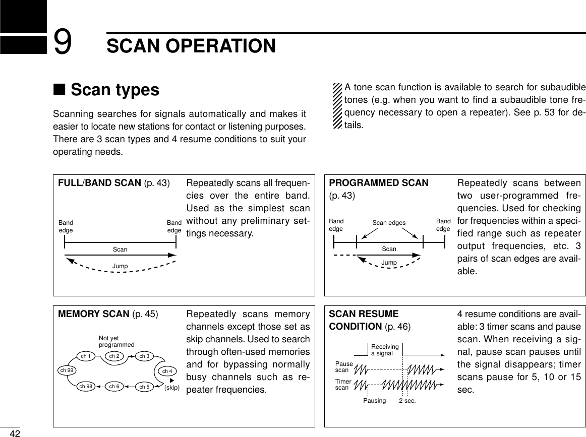
![439SCAN OPERATION■Full/programmed scanqSelect VFO mode with the desired band’s [V/MH].•Push [CHG/L] if [V/MH] is not displayed.wMake sure the squelch is set to the threshold point.ePush [(M/C)SCN] for 2 sec. to enter scan screen.•If the pocket beep function is activated, the transceiver automat-ically selects the tone squelch function when the scan screen isselected.rPush [SEL] one or more times to select the desired scanedges, if necessary. See p. 44 for details.•“AL” for full scan, “AA” for air band scan (U.S.A. and S. Americaversions only), “A1”/“A4” for 144 MHz/430(440) MHz band scanor “P1”–“P3” for programmed scan.•Only programmed scan edges can be selected.tPush [PRO] momentarily to start the scan.•Decimal point flashes while scanning.•“AL,” “AA”/“A1”/“A4” or “P1”– “P3” flashes to indicate full scan,band scan or programmed scan edges, respectively.•To change the scanning direction, rotate the desired band’s tun-ing dial.•To change the scan edges, push [SEL] one or more times.yTo stop the scan, push [PRO] again.uPush [(MAIN)í] for 2 sec. to exit the scan screen.If the same frequencies are programmed into a pair ofscan edges, programmed scan does not start.For programmed scan, scan edges must be programmedin advance. Program scan edges into scan edge memorychannels (1A–3B). (p. 32)qSelect the desired band with [BAND].wSelect VFO mode with [VFO].ePush [SQLY] or [SQLZ] to set the squelch tothe threshold point.rSelect the desired scan edges using the con-troller unit, if necessary. See p. 44 for details.•“AL” for full scan, “AA” for air band scan (U.S.A. andS. America versions only), “A1”/“A4” for 144 MHz/430(440) MHz band scan or “P1”–“P3” for pro-grammed scan.•Only programmed scan edges can be selected.tPush [wSCAN] momentarily to start a scan.Push [Y]/[Z] for 2 sec. to start a band scan.•“AL,” “AA”/“A1”/“A4” or “P1”–“P3” flashes to indicatefull scan, band scan or programmed scan edges, re-spectively.yPush [Y], [Z] or [ECLR] to cancel the scan.M-LSCANP1144.2-145.8Resume Pause145.32012MAIN433.00012íMAINPRIOPROTONResSELSCPMAINTSV/MHSCNM/CLOWMONIMID-LOY Z](https://usermanual.wiki/ICOM-orporated/IC-2800H/User-Guide-23181-Page-47.png)
![■Selecting scan edgesThe scanning range can be set to all frequencies (full scan) orbetween two user-programmed frequencies (programmedscan).Scan edges can be programmed in the same manner asmemory channels. Scan edges are programmed into scanedges, 1A/1B to 3A/3B, in memory channels. (p. 32)qPush [(M/C)SCN] for 2 sec. to enter the scan screen.•Push [CHG/L] if [(M/C)SCN] is not displayed.•If the pocket beep function is activated, the transceiver automat-ically selects the tone squelch function when the scan screen isselected.wPush [SEL] one or more times to select the desired scanedges, if necessary.•“AL” for full scan, “AA” for air band scan (U.S.A. and S. Americaversions only), “A1”/“A4” for 144 MHz/430(440) MHz band scanor “P1”–“P3” for programmed scan.•Only programmed scan edges can be selected.ePush [(MAIN)í] for 2 sec. to exit the scan screen.Scan edge selection may not be performed fromthe microphone.449SCAN OPERATIONM-LSCANP1144.2-145.8Resume Pause145.32012MAIN433.00012íMAINPRIOPROTONResSELSCPMAINTSV/MHSCNM/CLOWMONIMID-LO](https://usermanual.wiki/ICOM-orporated/IC-2800H/User-Guide-23181-Page-48.png)
![459SCAN OPERATION■Memory scanqSelect memory mode with the desired band’s [M/C].•Push [CHG/L] if [M/C] is not displayed.•“!” appears when memory mode is selected.wMake sure the squelch is set to the threshold point.ePush [(M/C)SCN] for 2 sec. to enter the scan screen.•If the pocket beep function is activated, the transceiver automat-ically selects the tone squelch function when the scan screen isselected.rPush [MEM] momentarily to start the scan.•Decimal point and“!” flash while scanning.•To change the scanning direction, rotate the desired band’s tun-ing dial.tTo stop the scan, push [MEM] again.yPush [(MAIN)í] for 2 sec. to exit the scan screen.qSelect the desired band with [BAND].wSelect memory mode with [MR].ePush [SQLY] or [SQLZ] to set the squelch tothe threshold point.rPush [wSCAN] momentarily or [Y]/[Z] for 2sec. to start memory scan.•Decimal point and“!” flash while scanning.tPush [Y], [Z] or [ECLR] to cancel the scan.At least 2 memory channels must be programmed formemory scan to start.Y ZM-LSCAN144.0-146.0Resume 15s145.32012MAIN433.00012íMAINPRIOMEMTONResSELSCPMAINTSV/MHSCNM/CLOWMONIMID-LOM](https://usermanual.wiki/ICOM-orporated/IC-2800H/User-Guide-23181-Page-49.png)
![469SCAN OPERATION■Skip channel settingMemory channels can be set to be skipped for memory skipscan. In addition, memory channels can be set to be skippedfor both memory skip scan and full/band/programmed scan(frequency skip scan). This is useful to speedup the scan in-terval.qSelect a memory channel you wish to set skip information.wPush the desired band’s [(MAIN)EDIT] for 2 sec. to enter theedit screen.•Push [CHG/L] if [(MAIN)EDIT] is not displayed.ePush [SKIP] to select the condition.•“≈” for memory skip scan.•“P≈” for frequency skip scan and memory skip scan.•No “≈” or “P≈” indication for no skipping of channels.rIf you want to set other channels, rotate the right-hand tun-ing dial. Repeat eto set the desired condition.•Push [CH] if memory channel does not flash.tPush [ï] to exit the edit screen.■Scan resume conditionThe scan resume condition can be selected as a pause ortimer scan for each band. When receiving signals, the scanpauses according to the scan resume condition.qPush the desired band’s [(M/C)SCN] for 2 sec. to enter scanscreen.•Push [CHG/L] if [(M/C)SCN] is not displayed.wPush [(SEL)Res] one or more times for 2 sec. to select con-dition.•“5s” : scan pauses for 5 sec. on a received signal.•“10s” : scan pauses for 10 sec. on a received signal.•“15s” : scan pauses for 15 sec. on a received signal.•“Pause” : scan pauses on a received signal until it disappears.ePush [(MAIN)í] for 2 sec. to exit scan screen.ïYZCHSKIPMWMEMORY EDIT(TS=12.5k)Name ICOM2800R-ToneC-ToneOW123.088.50.6000145.32012PSkip channelinformationM-LSCANP1144.2-145.8Resume 15s145.32012MAIN433.00012íMAINPRIOPROTONResSELSCPMAINTSV/MHSCNM/CLOWMONIMID-LO15 sec. resume time](https://usermanual.wiki/ICOM-orporated/IC-2800H/User-Guide-23181-Page-50.png)
![4710BAND SCOPE■OperationThe band scope function allows you to visually check a spec-ified frequency range. Sweep range varies ±50 kHz through±500 kHz with setting of the sweep tuning steps.Receive audio is muted while monitoring the band scope.Push [SWP] to cancel sweeping and receive the audio.qSet the desired frequency as band scope center frequency.wPush the desired band’s [(MAIN)SCP] for 2 sec. to select theband scope screen.•Push [CHG/L] if [(MAIN)SCP] is not displayed.eA sweep automatically starts and signal conditions(strengths) appear starting from the center of the range.rPush [SWP] momentarily to begin another sweep.•“ ” appears while sweeping.tPush [(SWP) ] for 2 sec. to begin sweeping continuously.•Push [SWP] again to cancel sweeping.yPush [TS] to select the sweep tuning step, if desired.•5, 10, 15, 20, 25, 30 and 50 kHz sweep tuning steps are availablewhen a tuning step other than 12.5 kHz is selected.•12.5, 25 and 50 kHz sweep tuning steps are available when 12.5kHz tuning step is selected.uRotate the desired band’s tuning dial to set the highlightedcursor to the desired waveform and set the frequency ofthe signal.•Push [CENT] to return the operating frequency to the center fre-quency.iPush [(MAIN)í] for 2 sec. to exit the band scope screen.MAINMAIN SCPM-LSWPCENT145.06012433.00012SCPMAINTSV/MHSCNM/CLOWMONIMID-LO10kTSMAIN](https://usermanual.wiki/ICOM-orporated/IC-2800H/User-Guide-23181-Page-51.png)
![■Priority watch typesPriority watch checks for signals on a frequency every 5 sec.while operating on a VFO frequency. The transceiver has 2priority watch types to suit your needs.The watch resumes according to the selected scan resumecondition. See p. 46 for details.■Priority watch operationqSelect VFO mode with the desired band’s [V/MH].•Push [CHG/L] if [V/MH] is not displayed.wSet an operating frequency.eMake sure the squelch is set to the threshold point.rSet the watching channel(s).For memory channel watch:Select the desired memory channel.•Select memory mode with the desired band’s [M/C] (“!”ap-pears.); select the memory channel to be watched with the de-sired band’s tuning dial.For memory scan watch:Start the memory scan.•Select memory mode with the desired band’s [M/C] (“!”ap-pears.); push [(M/C)SCN] for 2 sec. to select scan screen; push[MEM] to start memory scan.For call channel watch:Select the call channel by pushing [M/C].•Select memory mode with the desired band’s [M/C]. (“C” ap-pears.)tPush [(M/C)SCN] for 2 sec. to select the scan screen.•If the pocket beep function is activated, the transceiver automat-ically selects the tone squelch function when scan screen is se-lected.4811 PRIORITY WATCHMEMORY or CALL CHANNEL WATCHWhile operating on a VFOfrequency, priority watchchecks for a signal on theselected memory or callchannel every 5 sec.•A memory channel with skip in-formation can be watched.MEMORY SCAN WATCH While operating on a VFOfrequency, priority watchchecks for signals on eachmemory channel in se-quence.•The memory skip function isuseful to speed up the scan.VFOfrequencyMemoryor callchannel5 sec. 125 msec.VFOfrequencyMch 1Mch 0Mch 2Mch 995 sec. 125 msec.≈Skip](https://usermanual.wiki/ICOM-orporated/IC-2800H/User-Guide-23181-Page-52.png)
![4911PRIORITY WATCHyPush [(MEM)PRIO] for 2 sec. to start the watch.•The transceiver checks the memory or call channel frequencyevery 5 sec.•The watch resumes according to the selected scan resume con-dition. (p. 46)•“PRIO” and decimal point blinks while receiving a signal on awatch channel.uPush [(MEM) PRIO] while the display shows the VFO fre-quency to stop the watch.qSelect the desired band with [BAND].wSelect VFO mode with [VFO].eSet an operating frequency.rPush [SQLY] or [SQLZ] to set the squelch tothe threshold point.tSet the watching channel(s).For memory channel watch:Select the desired memory channel.•Select memory mode with [MR]; select the memorychannel to be watched with [Y]/[Z].For memory scan watch:Start the memory scan.•Select memory mode with [MR]; push [wSCAN]momentarily or [Y]/[Z] for 2 sec. to start memoryscan.For call channel watch:Select the call channel by pushing [(MR)CALL]for 2 sec.yPush [ePRIO] to start the watch.•The transceiver checks the memory or call channelfrequency every 5 sec.•The watch resumes according to the selected scanresume condition. (p. 46)•“PRIO” and decimal point blinks while receiving asignal on a watch channel.uPush [ePRIO] or [ECLR] while the displayshows the VFO frequency to stop the watch.PRIOM-LSCANResume 15s145.32012MAIN433.00012íMAINPRIOMEMTONResSELSCPMAINTSV/MHSCNM/CLOWMONIMID-LOMRXPRIO3](https://usermanual.wiki/ICOM-orporated/IC-2800H/User-Guide-23181-Page-53.png)
![5012 SUBAUDIBLE TONE OPERATION■Tone squelch operationThe tone squelch opens only when receiving a signal con-taining a matching subaudible tone. You can silently wait forcalls from group members using the same tone.qSelect the desired band with the desired band’s [MAIN].wSet an operating frequency.eSet the desired CTCSS tone using the edit screen.•See right for programming.rPush [TON] one or more times until “TSQL” appears in thefunction display.•Push [CHG/L] if [TON] is not displayed.tWhen the received signal includes a matching tone,squelch opens and the signal can be heard.•When the received signal’s tone does not match, tone squelchdoes not open, however, the S-indicator shows signal strength.•To open the squelch manually, push [MONI].yOperate the transceiver in the normal way.uTo cancel the tone squelch, push [TON] one or more timesto clear “TSQL.”➲CONVENIENTStore subaudible tone frequencies and tone squelch ON/OFFsettings in memories (call) for easy recall.qSelect the desired band with [BAND].wSet an operating frequency.eSet the desired CTCSS tone in the edit screenusing the remote controller unit.•See right for programming.rPush [FUNC] then [oTSQL] to activate thetone squelch.tWhen the received signal includes a matchingtone, squelch opens and the signal can beheard.•When the received signal’s tone does not match,tone squelch does not open, however, the S-indica-tor shows signal strength.•To open the squelch manually, push [qMONI].yOperate the transceiver in the normal way.uTo cancel the tone squelch, push [FUNC] then[GT-OFF].TSQL9](https://usermanual.wiki/ICOM-orporated/IC-2800H/User-Guide-23181-Page-54.png)
![5112SUBAUDIBLE TONE OPERATIONDSetting subaudible tones for tone squelchoperation (CTCSS tones)Separate tone frequencies can be set for tone squelch oper-ation than for repeater operation (the same range of tones isavailable). Like repeater tones, these are set in the editscreen.qSelect the mode/channel you wish to set the CTCSS tonefrequency to, such as VFO mode or memory/call channel.wPush the desired band’s [(MAIN)EDIT] for 2 sec. to enter theedit screen.•Push [CHG/L] if [(MAIN)EDIT] is not displayed.ePush [Y] or [Z] to select the ‘C-Tone’ item.•Left-hand tuning dial can also select the item.rRotate the right-hand tuning dial to select the desired fre-quency.•The CTCSS tone frequency is set temporarily. Push [MW] for 2sec. to store the tone frequency permanently.•The color of the frequency indication changes when the setting isdifferent from the memory or call channel contents.tIf you want to set other channels, push [CH] then rotate theright-hand tuning dial. Repeat eand rto select the de-sired frequency.yPush [ï] to exit the edit screen.The tone frequency can be set in a memory channel tem-porarily. However, the set contents are cleared once theother memory/call channel is selected. To store the tonefrequency permanently, push [MW] for 2 sec. at step rtooverwrite the information.•Available CTCSS tone frequencies (unit: Hz)The transceiver has 50 tone frequencies and consequentlytheir spacing is narrow. Therefore, some tone frequenciesmay receive interference from adjacent tone frequencies.67.069.371.974.477.079.782.585.488.591.594.897.4100.0103.5107.2110.9114.8118.8123.0127.3131.8136.5141.3146.2151.4156.7159.8162.2165.5167.9171.3173.8177.3179.9183.5186.2189.9192.8196.6199.5203.5206.5210.7218.1225.7229.1233.6241.8250.3254.1ïYZCHSKIPMWMEMORY EDIT(TS=12.5k)Name ICOM2800R-ToneC-ToneOW88.5123.00.6000145.32012](https://usermanual.wiki/ICOM-orporated/IC-2800H/User-Guide-23181-Page-55.png)
![5212 SUBAUDIBLE TONE OPERATION■Pocket beep operationThis function uses subaudible tones for calling and can beused as a “common pager” to inform you that someone hascalled while you were away from the transceiver.DWaiting for a call from a specific stationqSelect the desired band with the desired band’s [MAIN].wSet an operating frequency.eSet the desired CTCSS tone using the edit screen.•See the previous page for programming.rPush [TON] one or more times until “TSQLì” appears inthe function display.•Push [CHG/L] if [TON] is not displayed.tWhen a signal with the correct tone is received, the trans-ceiver emits beep tones for 30 sec. and flashes “ì.”yPush [PTT] to answer or push [TON] to stop the beeps andflashing.•Tone squelch is automatically selected.uTo cancel the pocket beep, push [TON] one or more timesto clear “TSQL.”DCalling a waiting station using pocket beepA subaudible tone matched with the station’s tone frequencyis necessary. Use the tone squelch on p. 50 or a subaudibletone encoder.qSelect the desired band with [BAND].wSet an operating frequency.eSet the desired CTCSS tone in the editscreen using the remote controller unit.•See the previous page for programming.rPush [FUNC] then [iTSQLS] to acti-vate the pocket beep.tWhen the received signal includes amatching tone, the transceiver emits beeptones for 30 sec. and flashes “ì.”yPush [PTT] to answer or push [ECLR] tostop the beeps and flashing.•Tone squelch is automatically selected.uTo cancel the pocket beep, push [FUNC]then [GT-OFF].TSQLS8](https://usermanual.wiki/ICOM-orporated/IC-2800H/User-Guide-23181-Page-56.png)
![5312SUBAUDIBLE TONE OPERATION■Tone scanThe transceiver can detect the subaudible tone frequency in areceived signal. By monitoring a signal that is being transmit-ted on a repeater input frequency, you can determine the tonefrequency required to access the repeater.qSet the desired frequency or memory channel to bechecked for a tone frequency.wTurn the tone squelch ON or OFF to check the tonesquelch frequency or repeater tone frequency, respectively.(p. 50)ePush the desired band’s [(M/C)SCN] for 2 sec. to enter thescan screen.•Push [CHG/L] if [(M/C)SCN] is not displayed.•If the pocket beep function is activated, the transceiver automat-ically selects the tone squelch function when the scan screen isselected.rPush [TON] momentarily to start the tone scan.•Decimal point flashes while scanning.•To change the scanning direction, rotate the desired band’s tun-ing dial.tWhen the tone frequency is detected, the tone scanpauses.•The tone frequency is set temporarily on a memory or call chan-nel. Program into the memory or call channel to store the tonefrequency permanently.•The decoded tone frequency is used for the repeater tone fre-quency or tone squelch frequency, depending on the tonesquelch ON/OFF setting.yTo stop the scan, push [TON] again.uPush [(MAIN)í] for 2 sec. to exit the scan screen.M-LSCANResume 15s250.312MAIN433.00012íMAINPRIOPROTONResSELSCPMAINTSV/MHSCNM/CLOWMONIMID-LO](https://usermanual.wiki/ICOM-orporated/IC-2800H/User-Guide-23181-Page-57.png)
![■Programming a DTMF codeDTMF codes are used for autopatching, accessing repeaters,controlling other equipment, etc. The transceiver has 14DTMF memory channels (D0–D9, DA–DD) for storage ofoften-used DTMF codes of up to 16 digits.qPush [DTMF] for 2 sec. to select the DTMF memoryscreen.•Push [CHG/L] if [DTMF] is not displayed.wPush [Y] or [Z] to select the desired DTMF memory.•Left-hand tuning dial can also select the item.ePush [EDIT] to enter programming mode.•The first character of the DTMF code flashes.rRotate the right-hand tuning dial to select the desired char-acter.•“E” stands for “M” and “F” stands for “#.”•“–” indicates ‘no code’ and can be used to clear a previously pro-grammed code.tPush [≈] to advance to the next character.•Push [Ω] to select the previous character.yRepeat rand tuntil the desired code is input.uPush [ï] to program the DTMF code and exit program-ming mode.iIf you want to set other channels, repeat wthrough u.oPush [ï] to exit the DTMF memory screen.5413 DTMF MEMORYDTMFD0D1D2D301234560123456789ABTx Time 100msTIMEEDITDTMFD0D1D2D301234560123456789ABTx Time 100msï](https://usermanual.wiki/ICOM-orporated/IC-2800H/User-Guide-23181-Page-58.png)
![■Transmitting a DTMF codeDAutomatic transmission (DTMF memory)The selected DTMF code is transmitted at each push of thePTT switch when the DTMF memory encoder is turned ON.qPush [DTMF] to turn the DTMF memory encoder ON.•Push [CHG/L] if [DTMF] is not displayed.•“ ” appears.wPush [DTMF] for 2 sec. to select the DTMF memoryscreen.ePush [Y] or [Z] to select the desired DTMF memory.•Left-hand tuning dial can also select the item.rPush [ï] to exit the DTMF memory screen.tPush [PTT] to transmit the selected DTMF code.•Each push of [PTT] transmits the DTMF code.•The speaker emits the DTMF tones sent.yPush [DTMF] to cancel the DTMF memory encoder.•“ ” disappears.qPush [FUNC] then [yDTMF] to turn the DTMFmemory encoder ON.•“ ” appears.wSet the desired DTMF memory in the DTMFmemory screen using the remote controllerunit.•Follow steps wthrough rabove.•See the previous page for programming.ePush [PTT] to transmit the selected DTMF code.•Each push of [PTT] transmits the DTMF code.rPush [ECLR] to cancel the function.DTransmitting a DTMF memory directlyqPush [FUNC] then [yDTMF] to turn the DTMFmemory encoder ON.•“ ” appears.wPush [DTMF-S] to activate the DTMF setting.•Function indicator on the HM-98 lights green.ePush the desired DTMF channel number.•“0” to “9” and “A” to “D” are available for channelnumbers.rPush [DTMF-S] again to deactivate the DTMFsetting.•Function indicator on the HM-98 disappears.tPush [ECLR] to turn the DTMF memory en-coder OFF.•When the DTMF memory encoder is turned ONcontinuously, each push of the PTT transmits thepreviously selected DTMF code.5513DTMF MEMORYDTMF6DTMF6](https://usermanual.wiki/ICOM-orporated/IC-2800H/User-Guide-23181-Page-59.png)
![■DTMF speedThe rate at which DTMF memories send individual DTMFcharacters can be set to accommodate operating needs.qPush [DTMF] for 2 sec. to select the DTMF memoryscreen.•Push [CHG/L] if [DTMF] is not displayed.wPush [TIME] one or more times to select the desiredspeed as shown in the table below.ePush [ï] to exit the DTMF memory screen.DISPLAY INTERVAL SPEED100ms 100 msec. 5.0 cps200ms 200 msec. 2.5 cps300ms 300 msec. 1.6 cps500ms 500 msec. 1.0 cps5613 DTMF MEMORYcps=characters/sec.DTMFD0D1D2D301234560123456789ABTx Time 100msTIMEEDIT](https://usermanual.wiki/ICOM-orporated/IC-2800H/User-Guide-23181-Page-60.png)
![■HM-90 switchesqPTT SWITCH➥Push and hold to transmit; release to receive.➥Toggles between transmitting and receiving while theone-touch PTT function is in use.wBAND SWITCHES [BAND SELECT YY,ZZ]➥Push to select the operating band.➥Activate the sub band access function after pushing[FUNC] on the HM-90 rear panel.eMONITOR SWITCH [MONI]Toggles the monitor function ON and OFF.rSQUELCH LEVEL UP/DOWN SWITCHES [YYSQL], [ZZSQL]Adjust the squelch level.tFREQUENCY UP/DOWN SWITCHES [UP], [DN]➥Push either switch to change the operating frequency,memory channel, set mode contents, etc.➥Push and hold either switch to start scanning.yACTIVITY INDICATORLights red while a key is pushed; lights green while theone-touch PTT function is in use.uAUDIO VOLUME UP/DOWN SWITCHES [YYVOL], [ZZVOL]Adjust the audio output level.iMODE INDICATORIndicates the microphone condition.•Lights red when [FUNC] is pushed.•Lights green when [DTMF KEY] is pushed.•Lights orange when [DTMF MEMO] is pushed.oLOCK SWITCH [LOCK]Locks all switches and keys on the microphone except forthe PTT switch.!0 KEYPADUsed for controlling the transceiver, transmitting a DTMFmemory channel, etc.5914WIRELESS OPERATIONBANDSELECTMONIREMOTE CONTROL MICROPHONEVOLSQL LOCKJAPANAFC AFC-OFF PTT-M MWPGRCALL123A456BM0# DMR VFO CLRC-SQL DTMF D-OFFSCANMONIFUNC DTMFKEY DTMFMEMOMUTE SQL ENT789CDUP– DUP+SIMP SPCHPRIO REAR LOCK DEMOTONEHIGH MID LOW SETT-SQLST-SQL T-OFF ➓➊➋➌➍➎➏➐➑➒Front and side panels Rear panel](https://usermanual.wiki/ICOM-orporated/IC-2800H/User-Guide-23181-Page-63.png)
![6014 WIRELESS OPERATIONKEY FUNCTIONSelects the call channel.Selects memory mode.Selects VFO mode.Selects high output power.Selects mid-high output power.Selects low output power.Selects –duplex.Selects +duplex.Selects simplex.Mutes audio signals.SECONDARY FUNCTION (after )No secondary function.No secondary function.Turns the one-touch PTT function ON andOFF.No secondary function.No secondary function.Turns the DTMF memory function ON.Turns the subaudible tone encoder ON.Turns the pocket beep function ON.Turns the tone squelch function ON.Starts and stops a priority watch.FUNCOTHER FUNCTIONS•After :Input the appropriate digitfor frequency or memorychannel selection.•After :Transmit the appropriateDTMF code.•After :Transmit the appropriateDTMF memory contents.[0] to [9], [A] to [D] can beused for DTMF memory.DTMFMEMODTMFKEYDENTDEMOAFCCALL1AFC-OFF2MRPTT-M3VFOPGR4HIGH5C-SQLMID6DTMFLOW7DUP–TONE8DUP+T-SQLS9SIMPT-SQL0MUTEPRIO](https://usermanual.wiki/ICOM-orporated/IC-2800H/User-Guide-23181-Page-64.png)
![6114WIRELESS OPERATIONKEY FUNCTIONClears a digit before entry.Cancels the scan, priority watch, orDTMF memory function.Enters set mode and advances the setmode selection order.Decreases the set mode selection orderafter entering set mode.NOTE:The IC-2800H has no voice synthesizerfunction.Sets the keypad for numeral input.Toggles between opening and closingthe squelch.No function.SECONDARY FUNCTION (after )Writes the VFO contents into the mem-ory channel or call channel.Advances the memory channel numberwhen continuously pushed after pro-gramming is completed.Turns the DTMF memory function OFF.Turns the subaudible tone encoder,pocket beep or tone squelch OFF.Enters and exits demonstration mode.Starts and stops scanning.Locks all the keys on the microphone’srear panel.FUNCOTHER FUNCTIONS•After :Transmit the appropriateDTMF code.[BMONI]Transmits a 1750 Hz tonecall signal for 0.5 sec.[ASQL]Transmits a 1750 Hz tonecall signal while pushing.DTMFKEYMWACLRBD-OFFSETCSPCHT-OFFDENTDEMOMSCANMONI#SQLREAR LOCK](https://usermanual.wiki/ICOM-orporated/IC-2800H/User-Guide-23181-Page-65.png)
![6214 WIRELESS OPERATION■Microphone addressThe transceiver has 8 possible microphone addresses (in-cluding OFF) to help prevent interference from other HM-90wireless microphones. Set both the microphone address andmicrophone dip switch to the same value as follows.When the supplied microphone is connected, the trans-ceiver rejects control signals from the HM-90 even whenthe microphone address is matched.DMicrophone addressqPush [(DISP)SET] for 2 sec. to enter set mode.•Push [CHG/L] if [(DISP)SET] is not displayed.wPush [Y] or [Z] to select the ‘HM-90 Address’ item.•Left-hand tuning dial can also select the item.eRotate the right-hand tuning dial to set the microphone ad-dress to 0–7 or to turn the microphone control OFF.•When “OFF” is selected, thetransceiver rejects all control sig-nals from the HM-90.rPush [ï] to exit set mode.qPush [FSET]; then push [FSET] or [GENT] toselect the ‘HM-90 Address’ item.wPush [Y] or [Z] to set the microphone addressto 0–7 or to turn the microphone control OFF.ePush [ECLR] to exit set mode.DMicrophone dip switchqRemove the switch cover from the microphone rear panel.wSet the microphone dip switch and the microphone ad-dress to the same value as shown below.eReplace the switch cover.MICROPHONE DIP SWITCHADDRESS S1-1 S1-2 S1-30 OFF OFF OFF1 (default) ON OFF OFF2 OFF ON OFF3ONONOFF4 OFF OFF ON5 ON OFF ON6 OFF ON ON7ONONONLOCKAFC AFC-OFF PTT-M MWPGRCALL123A456BMR VFO CLRC-SQL DTMF D-OFFHIGH MID LOW SETSwitch coverDip switch (S1)ONOFF123ïYZSETSquelch Delay Long1HM-90 AddressSub Band MuteSETB](https://usermanual.wiki/ICOM-orporated/IC-2800H/User-Guide-23181-Page-66.png)
![6315OTHER FUNCTIONS■Beep tonesYou can select silent operation by turning beep tones OFF oryou can select to have confirmation beeps sound at the pushof a switch by turning beep tones ON.qPush [(DISP)SET] for 2 sec. to enter set mode.•Push [CHG/L] if [(DISP)SET] is not displayed.wPush [Y] to select the ‘Operation Beep’ item.•Left-hand tuning dial can also select the item.eRotate the right-hand tuning dial to turn the confirmationbeep ON or OFF.rPush [ï] to exit set mode.qPush [FSET] to enter set mode.wPush [FSET] to select the ‘Operation Beep’item.ePush [Y] or [Z] to turn the confirmation beepON or OFF.rPush [ECLR] to exit set mode.■Time-out timerTo prevent accidental prolonged transmission with the one-touch PTT function, etc., the transceiver has a time-out timer.This timer cuts a transmission OFF after 3, 5, 15 or 30 min. ofcontinuous transmission. This timer can be cancelled (de-fault).Approx. 10 sec. before the time-out timer is activated, thetransceiver emits a beep tone as a warning.qPush [(DISP)SET] for 2 sec. to enter set mode.•Push [CHG/L] if [(DISP)SET] is not displayed.wPush [Y] or [Z] to select the ‘Tx T.O.T.’ item.•Left-hand tuning dial can alsoselect the item.eRotate the right-hand tuningdial to select the desired time-out time or turn the timer OFF.rPush [ï] to exit set mode.qPush [FSET] to enter set mode.wPush [FSET] or [GENT] to select the ‘TxT.O.T.’ item.ePush [Y] or [Z] to select the desired time-outtime or turn the timer OFF.rPush [ECLR] to exit set mode.ïYZSETOperation Beep ONOFFOFFOFFAutoTx T.O.T.Auto RepeaterAuto Power-OffCooling FanïYZSETOperation Beep ONOFFOFFOFFAutoTx T.O.T.Auto RepeaterAuto Power-OffCooling FanSETBSETB](https://usermanual.wiki/ICOM-orporated/IC-2800H/User-Guide-23181-Page-67.png)
![6415 OTHER FUNCTIONS■Auto power-off functionThe transceiver can be set to automatically turn OFF after aspecified period in which no operations are performed.2 hours, 1 hour, 30 min. and OFF can be specified. The spec-ified period is retained even when the transceiver is turnedOFF by the auto power-off function. To cancel the function,select “OFF” in step ebelow.qPush [(DISP)SET] for 2 sec. to enter set mode.•Push [CHG/L] if [(DISP)SET] is not displayed.wPush [Y] or [Z] to select the ‘Auto Power-Off’ item.•Left-hand tuning dial can alsoselect the item.eRotate the right-hand tuningdial to select the desired autopower-off time or turn thefunction OFF.rPush [ï] to exit set mode.qPush [FSET] to enter set mode.wPush [FSET] or [GENT] to select the ‘AutoPower-Off’ item.ePush [Y] or [Z] to select the desired autopower-off time or turn the function OFF.rPush [ECLR] to exit set mode.■Cooling fanThe transceiver has a heatsink and cooling fan to radiateheat. The cooling fan automatically turns ON while transmit-ting and remains ON for 2 min. after transmitting. The cool-ing fan can be activated continuously, if desired.qPush [(DISP)SET] for 2 sec. to enter set mode.•Push [CHG/L] if [(DISP)SET] is not displayed.wPush [Y] or [Z] to select the ‘Cooling Fan’ item.•Left-hand tuning dial can alsoselect the item.eRotate the right-hand tuningdial to set the cooling fan toautomatic (“Auto”) or contin-uous (“ON”).rPush [ï] to exit set mode.qPush [FSET] to enter set mode.wPush [FSET] or [GENT] to select the ‘CoolingFan’ item.ePush [Y] or [Z] to set the cooling fan to auto-matic (“Auto”) or continuous (“ON”).rPush [ECLR] to exit set mode.ïYZSETOperation Beep ONOFFOFFOFFAutoTx T.O.T.Auto RepeaterAuto Power-OffCooling FanïYZSETAuto Power-Off OFFAuto1200Long1Cooling FanPacket BPSSquelch DelayHM-90 AddressSETBSETB](https://usermanual.wiki/ICOM-orporated/IC-2800H/User-Guide-23181-Page-68.png)
![6515OTHER FUNCTIONS■Squelch delayDuring operation, received signal strength often fluctuates.This can result in annoying repeated opening and closing ofthe squelch during reception of the same signal. The trans-ceiver has a built-in squelch delay function which helps pre-vent this. When both stations are operating from a fixedlocation e.g. during packet operation, this function should beset to “short.”qPush [(DISP)SET] for 2 sec. to enter set mode.•Push [CHG/L] if [(DISP)SET] is not displayed.wPush [Y] or [Z] to select the ‘Squelch Delay’ item.•Left-hand tuning dial can alsoselect the item.eRotate the right-hand tuningdial to set the squelch delayto “Long” or “Short.”rPush [ï] to exit set mode.qPush [FSET] to enter set mode.wPush [FSET] or [GENT] to select the ‘SquelchDelay’ item.ePush [Y] or [Z] to set the squelch delay to“Long” or “Short.”rPush [ECLR] to exit set mode.■Sub band muteThe sub band mute function automatically cuts out sub bandAF signals when a main band signal is received.“ ” appears while the sub band mute is activated.qPush [(DISP)SET] for 2 sec. to enter set mode.•Push [CHG/L] if [(DISP)SET] is not displayed.wPush [Y] or [Z] to select the ‘Sub Band Mute’ item.•Left-hand tuning dial can alsoselect the item.eRotate the right-hand tuningdial to turn the sub bandmute function ON or OFF.rPush [ï] to exit set mode.qPush [FSET] to enter set mode.wPush [FSET] or [GENT] to select the ‘SubBand Mute’ item.ePush [Y] or [Z] to turn the sub band mutefunction ON or OFF.rPush [ECLR] to exit set mode.ïYZSETAuto Power-Off OFFAuto1200Long1Cooling FanPacket BPSSquelch DelayHM-90 AddressSETBïYZSETSquelch Delay Long1OFFOFFONHM-90 AddressSub Band MuteSub Band BeepRF AttenuatorSETB](https://usermanual.wiki/ICOM-orporated/IC-2800H/User-Guide-23181-Page-69.png)
![6615 OTHER FUNCTIONS■Sub band busy beepThe sub band busy beep sounds when the sub band’ssquelch is closed to inform you that the sub band’s squelchhas been opened.qPush [(DISP)SET] for 2 sec. to enter set mode.•Push [CHG/L] if [(DISP)SET] is not displayed.wPush [Y] or [Z] to select the ‘Sub Band Beep’ item.•Left-hand tuning dial can alsoselect the item.eRotate the right-hand tuningdial to turn the sub bandbusy beep ON or OFF.rPush [ï] to exit set mode.qPush [FSET] to enter set mode.wPush [FSET] or [GENT] to select the ‘SubBand Beep’ item.ePush [Y] or [Z] to turn the sub band busy beepON or OFF.rPush [ECLR] to exit set mode.■Automatic RF attenuatorThe attenuator prevents a desired signal from distorting whenvery strong signals are near the desired frequency, etc.The transceiver’s RF attenuator is linked to the [SQL] setting.The attenuator is automatically activated when [SQL] is ro-tated clockwise past the 12 o’clock position. Approx. 10 dB at-tenuation is obtained at full rotation. This function can beturned ON or OFF in set mode.qPush [(DISP)SET] for 2 sec. to enter set mode.•Push [CHG/L] if [(DISP)SET] is not displayed.wPush [Y] or [Z] to select the ‘RF Attenuator’ item.•Left-hand tuning dial can alsoselect the item.eRotate the right-hand tuningdial to turn the automaticRF attenuator ON or OFF.rPush [ï] to exit set mode.qPush [FSET] to enter set mode.wPush [FSET] or [GENT] to select the ‘RF At-tenuator’ item.ePush [Y] or [Z] to turn the automatic RF atten-uator ON or OFF.rPush [ECLR] to exit set mode.ïYZSETSquelch Delay Long1OFFOFFONHM-90 AddressSub Band MuteSub Band BeepRF AttenuatorSETBïYZSETSub Band BeepOFFOFFOFFVHF M/C UHF M/C RF AttenuatorMemory NameHM-98 F-1HM-98 F-2SETB](https://usermanual.wiki/ICOM-orporated/IC-2800H/User-Guide-23181-Page-70.png)
![6715OTHER FUNCTIONS■Memory name indicationThe transceiver can displaymemory names programmedin memory or call channels. (p.32)qPush [(DISP)SET] for 2 sec. to enter set mode.•Push [CHG/L] if [(DISP)SET] is not displayed.wPush [Y] or [Z] to select the ‘Memory Name’ item.•Left-hand tuning dial can alsoselect the item.eRotate the right-hand tuningdial to turn the memoryname indication ON or OFF.rPush [ï] to exit set mode.qPush [FSET] to enter set mode.wPush [FSET] or [GENT] to select the ‘MemoryName’ item.ePush [Y] or [Z] to turn the memory name indi-cation ON or OFF.rPush [ECLR] to exit set mode.■HM-98 [F-1]/[F-2] keysSwitches on the transceiver’s front panel can be assigned tothe HM-98 [F-1] and [F-2] keys. The following can be as-signed:V/U MAIN : [MAIN(SCP)] V/U V/MHz : [V/MH(TS)]V/U M/C : [M/C(SCN)] V/U MONI : [MONI(LOW)]V/U EDIT : [MAIN(EDIT)] V/U TONE : [TON(DUP)]V/U MW : [S.MW(MW)] DTMF : [DTMF]DISP : [DISP(SET)] Up : Microphone’s upDn : Microphone’s downqPush [(DISP)SET] for 2 sec. to enter set mode.•Push [CHG/L] if [(DISP)SET] is not displayed.wPush [Y] or [Z] to select the ‘HM-98 F-1’ or ‘F-2’ item.•Left-hand tuning dial can alsoselect the item.eRotate the right-hand tuningdial to select the desiredfunction.rPush [ï] to exit set mode.qPush [FSET] to enter set mode.wPush [FSET] or [GENT] to select the ‘HM-98F-1’ or ‘F-2’ item.ePush [Y] or [Z] to select the desired function.rPush [ECLR] to exit set mode.ïYZSETSub Band BeepOFFOFFOFFVHF M/C UHF M/C RF AttenuatorMemory NameHM-98 F-1HM-98 F-2ïYZSETMemory Name OFFVHF M/C UHF M/C Up Dn HM-98 F-1HM-98 F-2HM-118 UpHM-118 Dn12EDITMAINDUPTONMID-LODISPSETMWS.MWEDITMWS.MWEDITMAINDUPTONICOM2800145.320MAINMID-LO12433.000JA3YUASETBSETB](https://usermanual.wiki/ICOM-orporated/IC-2800H/User-Guide-23181-Page-71.png)
![6815 OTHER FUNCTIONS■HM-97/118 [UP]/[DN] keysSwitches on the transceiver’s front panel can be assigned tothe HM-97/118 [UP] and [DN] keys. The following can be as-signed:V/U MAIN : [MAIN(SCP)] V/U V/MHz : [V/MH(TS)]V/U M/C : [M/C(SCN)] V/U MONI : [MONI(LOW)]V/U EDIT : [MAIN(EDIT)] V/U TONE : [TON(DUP)]V/U MW : [S.MW(MW)] DTMF : [DTMF]DISP : [DISP(SET)] Up : Microphone’s upDn : Microphone’s downqPush [(DISP)SET] for 2 sec. to enter set mode.•Push [CHG/L] if [(DISP)SET] is not displayed.wPush [Y] or [Z] to select the ‘HM-118 Up’ or ‘Dn’ item.•Left-hand tuning dial can alsoselect the item.eRotate the right-hand tuningdial to select the desiredfunction.rPush [ï] to exit set mode.qPush [FSET] to enter set mode.wPush [FSET] or [GENT] to select the ‘HM-118Up’ or ‘Dn’ item.ePush [Y] or [Z] to select the desired function.rPush [ECLR] to exit set mode.[UP] or [DN] key assignment is available for the micro-phones which have [UP]/[DN] switches except the HM-98.■Display contrastThe contrast of the LCD can be adjusted from 0% to 100% in3 or 4% steps. Adjust contrast to suit lighting conditions andpersonal preferences.qPush [DISP] to enter display set mode.•Push [CHG/L] if [DISP] is not displayed.wPush [Y] to select the ‘Contrast’ item.•Left-hand tuning dial can also select the item.eRotate the right-hand tuning dial to select the desired con-trast.rPush [ï] to exit display set mode.ïYZSETMemory Name OFFVHF M/C UHF M/C Up Dn HM-98 F-1HM-98 F-2HM-118 UpHM-118 DnïYZDISPLAYContrast 50%38%BrightMy CallDisplay Type ASETB](https://usermanual.wiki/ICOM-orporated/IC-2800H/User-Guide-23181-Page-72.png)
![6915OTHER FUNCTIONS■Display brightnessThe brightness of the LCD can be adjusted from 0% to 100%in 3 or 4% steps. Adjust brightness to suit lighting conditionsand personal preferences.qPush [DISP] to enter display set mode.•Push [CHG/L] if [DISP] is not displayed.wPush [Y] or [Z] to select the ‘Bright’ item.•Left-hand tuning dial can also select the item.eRotate the right-hand tuning dial to select the desiredbrightness.rPush [ï] to exit display set mode.■Indication typeThe indication type can be selected from 4 types.qPush [DISP] to enter display set mode.•Push [CHG/L] if [DISP] is not displayed.wPush [Y] or [Z] to select the ‘Display Type’ item.•Left-hand tuning dial can also select the item.eRotate the right-hand tuning dial to select the desired indi-cation type.rPush [ï] to exit display set mode.■My call functionThe opening title when turning power ON can be changed toyour call sign, etc. Up to 8 characters can be programmed.qPush [DISP] to enter display set mode.•Push [CHG/L] if [DISP] is not displayed.wPush [Z] to select the ‘My Call’ item.•Left-hand tuning dial can also select the item.ePush [EDIT] to enter programming mode.•The first character of the name flashes.rRotate the right-hand tuning dial to select the desired char-acter.•A to Z, 0 to 9, – (hyphen) and space are available.tPush [≈] to advance to the next character.•Push [Ω] to select the previous character.yRepeat rand tuntil the desired name is input.uPush [ï] to program the name and exit programmingmode.iPush [ï] again to exit display set mode.ïYZDISPLAYContrast 50%BrightMy CallDisplay Type AEDIT38%](https://usermanual.wiki/ICOM-orporated/IC-2800H/User-Guide-23181-Page-73.png)
![7015 OTHER FUNCTIONS■Packet operationDData speedFor packet operation, the transceiver can be set to one of twodata speeds: 1200 bps (default) or 9600 bps.qPush [(DISP)SET] for 2 sec. to enter set mode.•Push [CHG/L] if [(DISP)SET] is not displayed.wPush [Y] or [Z] to select the ‘Packet BPS’ item.•Left-hand tuning dial can alsoselect the item.eRotate the right-hand tuningdial to select the desireddata speed.rPush [ï] to exit set mode.qPush [FSET] to enter set mode.wPush [FSET] or [GENT] to select the ‘PacketBPS’ item.ePush [Y] or [Z] to select the desired dataspeed.rPush [ECLR] to exit set mode.For 1200 bps operation—•Disconnect the microphone plug from the microphoneconnector during data transmission, otherwise the datasignal and voice signal are simultaneously transmitted.For 9600 bps operation—•When the transceiver is set for 9600 bps data transmis-sion in set mode, the microphone signal is automaticallycut. Therefore, it is not necessary to disconnect the mi-crophone plug from the connector in this case.•When pushing [PTT] during data transmission, data trans-mission is interrupted and voice signals have priority.ïYZSETAuto Power-Off OFFAuto1200Long1Cooling FanPacket BPSSquelch DelayHM-90 AddressSETB](https://usermanual.wiki/ICOM-orporated/IC-2800H/User-Guide-23181-Page-74.png)
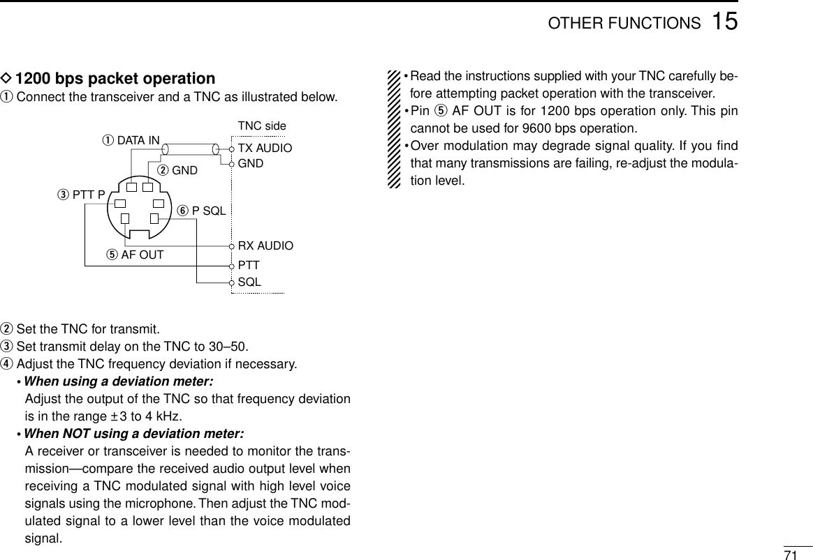
![7215 OTHER FUNCTIONSD9600 bps high speed packet operationThe transceiver supports 2 modes of 9600 bps packet opera-tion: G3RUH and GMSK.qConnect the transceiver and a TNC as illustrated below.wG3RUH mode can handle 16 kinds of modulated waveforms in order to maintain a communication link.eSet transmit delay on the TNC to 30–50.rAdjust the TNC frequency deviation if necessary (see pageat right).•When using the PTTP terminal for packet operation, novoice signals are transmitted from the microphone.•When pushing [PTT] during data transmission, data trans-mission is interrupted and the voice signal takes priority.•Read the instructions supplied with your TNC carefully be-fore attempting packet operation with the transceiver.•Pin rDATA OUT is for 9600 bps operation only. This pincannot be used for 1200 bps operation.TNC sideSQLPTTRX AUDIOGNDTX AUDIOq DATA INw GNDe PTT P r DATA OUTy P SQL](https://usermanual.wiki/ICOM-orporated/IC-2800H/User-Guide-23181-Page-76.png)
![7315OTHER FUNCTIONSDAdjusting the transmit signal output fromthe TNCWhen setting data transmission speed to 9600 bps, the datasignal coming from the TNC is applied exclusively to the in-ternal limiter circuitry to automatically maintain band width.NEVER apply data levels from the TNC of over 0.6 Vp-p, oth-erwise the transceiver will not be able to maintain the bandwidth and may possibly interfere with other stations.1.When using a level meter or synchroscope, adjust theTX audio output level (DATA IN level) from the TNC asfollows.0.4 Vp-p (0.2 Vrms) : recommended level0.2 Vp-p–0.5 Vp-p (0.1 Vrms–0.25 Vrms) : acceptable level2.When NOT using a measuring device.qConnect the transceiver to a TNC.wEnter a test mode (“CAL”, etc.) on the TNC, then transmitsome test data.eWhen the transceiver fails to transmit the test data or trans-mits sporadically (TX indicator doesn’t appear or flashes):- Decrease the TNC output level until the transmit indicatorlights continuously.When transmission is not successful even though the TXindicator lights continuously:- Increase the TNC output level.■Video monitor functionThe LCD can be used as a video monitor for an NTSC or PALvideo signal.NTSC : U.S.A., Australia, Asia, Latin America, Korea andTaiwan versionsPAL : Europe and Italy versionsqPush [DISP] to enter display set mode.•Push [CHG/L] if [DISP] is not displayed.wPush [ ] to monitor a video signal.•The video signal is displayed on the LCD.ePush any switch except [POWER] to return to display setmode.rPush [ï] to exit display set mode.to [VIDEO IN]](https://usermanual.wiki/ICOM-orporated/IC-2800H/User-Guide-23181-Page-77.png)
![7415 OTHER FUNCTIONS■Demonstration displayA demonstration function is available at power ON. This func-tion gives you a quick visual introduction to the function dis-play indicators.qWhile pushing [CHG/L], push [POWER] to turn power ON.•The transceiver cycles through a visual tour of the function dis-play indicators.wPush any switch to exit demonstration mode and enter thenormal operating condition temporarily.The transceiver automatically returns to demonstrationmode after 2 min. in which no operations are performed.To deactivate the demonstration display permanently, turnpower OFF, then while pushing [CHG/L], turn power ONagain.■AM/FM narrow modeFM narrow mode is only available for the Europe and Italy ver-sions. AM mode (receive only) is only available for the U.S.A.and S. America versions. Typically, AM mode is used for theair band (118–135.995 MHz).When pushing [PTT], a beep tone sounds indicating themode is AM mode. The transceiver cannot transmit in AMmode.qSelect the mode/channel you wish to set the mode to, suchas VFO mode or memory/call channel.wPush the desired band’s [(MAIN)EDIT] for 2 sec. to enter theedit screen.•Push [CHG/L] if [(MAIN)EDIT] is not displayed.ePush [MODE] to set the mode to FM wide/FM narrow orAM/FM wide.rIf you want to set other channels, rotate the right-hand tun-ing dial. Repeat eto select the desired frequency.tPush [ï] to exit the edit screen.The Europe and Italy versions of the IC-2800H comply withEuropean regulations regarding narrow FM bandwidth op-eration on amateur transceivers. Wide and narrow FM op-eration differ in specifications.■Fuse replacementIf the fuse blows or the transceiver stops functioning, find thesource of the problem if possible, and replace the damagedfuse with a new, rated one (FGB 20 A) as shown below.20 A](https://usermanual.wiki/ICOM-orporated/IC-2800H/User-Guide-23181-Page-78.png)
![7515OTHER FUNCTIONS■Partial resetIf you want to initialize the operating conditions (VFO fre-quency, VFO settings, set mode contents) without clearing thememory contents, a partial resetting function is available forthe transceiver.Band conditions can be reset independently.DVHF band partial resetting➥While pushing the 2nd switch from the top on the left side,turn power ON to partially reset the transceiver.•“144M VFO Clear” appears when resetting the VHF band condi-tion.DUHF band partial resetting➥While pushing the 2nd switch from the top on the right side,turn power ON to partially reset the transceiver.•“430M (440M) VFO Clear” appears when resetting the UHF bandcondition.DPartial resetting of both bands➥While pushing the 2nd switches from the top on both theleft and right sides, turn power ON to partially reset thetransceiver.•“VFO Clear” appears when resetting the VHF and UHF bandcondition.■All resetThe function display may occasionally display erroneous in-formation (e.g. when first applying power). This may becaused externally by static electricity or by other factors.If this problem occurs, turn power OFF. After waiting a fewseconds, turn power ON again. If the problem persists, per-form the following procedure.•Partial resetting is also available. See previous section for details.CAUTION: Resetting the transceiver CLEARS all mem-ory information and initializes all values in the transceiver.➥While pushing the 3rd switches from the top on both the leftand right sides, turn power ON to reset the CPU.•“Memory Clear” appears when resetting the CPU.[POWER]All resetUHF partial resetVHF partial reset](https://usermanual.wiki/ICOM-orporated/IC-2800H/User-Guide-23181-Page-79.png)
![■Getting startedDThis cloning software is designed to perform data settingand cloning for the IC-2800H DUAL BAND FM transceiver.DHELP WINDOW: Each item has a help window to describefunctions and operation.■System requirementsTo use this program, the following hardware and software arerequired:•IBM PC/AT compatible computer•An RS-232C serial port•Microsoft®Windows®95 or Microsoft®Windows®98•Intel i486DX4 processor or faster•At least 16 MB RAM•At least 640 ×480 pixel display•OPC-478 CLONING CABLE■Software installationNOTE: Before using the program, make a backup copy ofthe original disk. After making a backup copy, keep theoriginal disk in a safe place.NOTE: Depending on your Windows®system files, the PCmay require rebooting. In this case, repeat the installationfrom the beginning.qBoot up Windows.•Quit all applications when Windows is running.wInsert backup disk into the appropriate floppy drive.eSelect ‘Run’ from the [Start] menu.rType the setup program name with full path name, thenpress the [Enter] key. (A:\SETUP [Enter])tFollow the prompts.yProgram group ‘CS-2800’ appears in the ‘Programs’ folderof the start menu.7616 CS-2800 CLONING SOFTWARE optional CS-2800 and OPC-478IC-2800HTo [430(440) MHz SP]to an RS-232CportDB9 female plug(incl. level converter circuit)PersonalcomputerOPC-478■ConnectionsAll cloning operations are performed fromthe computer’s keyboard—the operation re-quired on the transceiver side is:while pushing the microphone [UP] switch +the 4th switch from the top on the left side,push [POWER] on the controller.](https://usermanual.wiki/ICOM-orporated/IC-2800H/User-Guide-23181-Page-80.png)
![■COM port/call sign setting•Set the com port (RS-232C port) number properly.•Enter your call sign.NOTE: ‘Check the following’ dialog box appears when theRS-232C serial port is not set correctly.NOTE: When first using this software, read out all thetransceiver cloning data into the PC before starting editingwith this cloning software. Otherwise the cloning data maynot be cloned properly to the transceiver. (e.g. operatingfrequency setting, mode selection, etc.)■Memory channel list descriptionqFILE MENU [File]Used for turning the software on/off, saving memory chan-nel contents or quitting the program, etc.wEDIT MENU [Edit]The memory channel can hold up to 99 channels + 3 pairsof programmed scan edges + 1 call channel.Each memory channel can be edited (copy, paste, clear,insert and delete) via the edit menu.eVIEW MENU [View]•UHF memory channel list, VHF memory channel list,DTMF autodial, Common settings (p. 79) screens are se-lectable.•Turn the tool bar or status bar on/off.rCOM PORT MENU [COM Port] Push to display the COM port setting dialog box.7716CS-2800 CLONING SOFTWAREq w e rtyu](https://usermanual.wiki/ICOM-orporated/IC-2800H/User-Guide-23181-Page-81.png)
![tCLONING MENU [Cloning] Push to display cloning menu and cloning information dia-log box.yHELP MENU [Help] Push to display one point help, help contents, cloning soft-ware revision information.uTool bar Short cut key appears on the tool bar when clicking the toolbar function in the [View] menu.■Edit menuThe ‘Edit Memory ch’ window allows you to edit the memorychannel information.The memory channel list can hold up 99 channels + 3 pairs ofprogrammed scan edges + 1 call channel.NOTE: ‘Narrow FM’ is available for the VHF band of theEurope and Italy versions only.NOTE: Read all the transceiver cloning data into the PCbefore starting editing with this cloning software, otherwisethe frequency data may not be cloned properly to yourtransceiver.■DTMF autodialThe transceiver has 14 DTMF memory channels (D0–D9,DA–DD) for storage of often-used DTMF codes of up to 16digits. One of these channels is encoded when the PTT ispushed.When slow DTMF speeds are required, the transceiver’s rateof DTMF transmission can be adjusted.“E” stands for “M” and “F” stands for “#.”7816 CS-2800 CLONING SOFTWARE](https://usermanual.wiki/ICOM-orporated/IC-2800H/User-Guide-23181-Page-82.png)
![■Common settingsThere are 3 setting menus available.Common : Commonly set items such as operationbeeps, sub band mute, sub band beep, RFattenuator, name display, TOT, auto repeater,auto power-off, cooling fan setting, packetdata speed, squelch delay, VHF/UHF scan re-sume timer and RF output power settings.Display : Sets LCD contrast and brightness.Select display type. Enter ‘Opening Title’ andclone ‘Comment.’MIC Option : Switches on the transceiver’s front panel canbe assigned to the microphone’s [F-1]/[F-2]for the HM-98 and [UP]/[DN] for the HM-97and HM-118/T/TA.■Exiting cloning mode➥After cloning is finished, push the [UP]/[DN] or [Y]/[Z] onthe microphone to exit the cloning mode and to return tonormal operating condition.•The [POWER] switch does not function in the cloning mode.DO NOT disconnect the controller cable while in thecloning mode.The transceiver remains in the cloning modeand continues in power ON condition.7916CS-2800 CLONING SOFTWARE](https://usermanual.wiki/ICOM-orporated/IC-2800H/User-Guide-23181-Page-83.png)
![8017 TROUBLESHOOTINGPROBLEM POSSIBLE CAUSE SOLUTION REF.No power comes on. •Power connector has a poor contact.•Polarity of the power connection is reversed.•Blown fuse.•Check the connector pins.•Reconnect the power cable observing theproper polarity. Replace the fuse, if damaged.•Check the cause, then replace the fuse.—pgs.15, 74p. 74No sound comes from thespeaker.•Volume level is too low.•The squelch level is set too tight.•A selective call or squelch function is activatedsuch as tone squelch or pocket beep.•Rotate [VOL] clockwise.•Open the squelch.•Turn the appropriate function OFF.p. 23p. 23pgs.50, 52Sub band signals are notaudible.•The sub band mute function is activated. •Turn the function OFF. p. 65No contact possible with an-other station.•The transceiver is set to semi-duplex.•The other station is using tone squelch. •Set to simplex.•Turn OFF tone squelch.p. 26p. 50Repeater cannot be ac-cessed.•Wrong offset frequency is programmed.•Wrong subaudible tone frequency is programmed. •Correct the offset frequency.•Correct the subaudible tone frequency.p. 30p. 29Frequency cannot be set. •The frequency lock function is activated.•Priority watch is paused on the watching fre-quency.•Turn the function OFF.•Push [(PRO)PRIO] or [(MEM)PRIO] to resumethe watch.p. 19p. 48Scan does not operate. •Squelch is open.•The selected programmed scan edge memorychannels (e.g. 1A/1B) have the same frequencies.•Only 1 memory channel is programmed or otherchannels are set as skip channels.•Set the squelch to the threshold point.•Reset the scan edges.•Program other memory channels or cancel thememory skip function in the desired channels.p. 23p. 44pgs.50, 52Transmission is automati-cally cut off.•Time-out timer is activated. •Set the timer to OFF. p. 63Transmission continueseven when PTT is released.•One-touch PTT function is activated. •Turn the function OFF. p. 25If your transceiver seems to be malfunctioning, please checkthe following points before sending it to a service center.](https://usermanual.wiki/ICOM-orporated/IC-2800H/User-Guide-23181-Page-84.png)
![8219 SPECIFICATIONSDGeneral•Frequency coverage : (Unit: MHz)U.S.A. Transmit 144–148, 430–450*1Receive 118–174*2, 430–450*1S. America Transmit 144–148, 430–440Receive 118–174*2, 400–530*3Europe, Tx/Rx 144–146, 430–440TaiwanItaly Transmit 144–148, 430–440Receive 136–174*2, 400–530*3Asia Transmit 144–148, 430–440Receive 136–174*2, 430–440*1Specifications guaranteed 440–450 MHz.*2Specifications guaranteed 144–148 MHz.*3Specifications guaranteed 430–440 MHz.•Mode : FM, AM (118–135.995; Rx only)•No. of memory channels : 232 (incl. 12 scan edges, 10 log,10 repeater and 2 call)•Tuning steps :5, 10, 12.5, 15, 20, 25, 30 and 50kHz•Frequency stability : ±10 ppm (–10°C to +60°C; +14°F to +140°F)•Power supply requirement: 13.8 V DC ±15% (negative ground)•Current drain (VHF/UHF; at 13.8 V DC):Transmit max. power 12.0 A/11.0 A*Receive standby 1.2 Amax. audio 1.8 A*8.0 A for Taiwan version.•Antenna connector : SO-239 (50 Ω)•Data connector : Mini DIN 6-pin•External video input : PHONO [RCA (75 Ω)]•Dimensions (projections not included):Controller 140(W)×70(H)×34(D) mm51⁄2(W)×23⁄4(H)×111⁄32(D) inMain unit 140(W)×40(H)×165.8(D) mm51⁄2(W)×19⁄16(H)×617⁄32(D) in•Weight (approx.) : Controller 290 g; 10.2 ozMain unit 1.15 kg; 2 lb 9 ozDTransmitter•Modulation system : Variable reactance•Output power (VHF/UHF) : High* 50 W/35 WMid-H* 20 W (approx.)Mid-L 10 W (approx.)Low 5 W (approx.)*25 W (High), 15 W (Mid-H) for both VHF and UHF for Taiwan ver-sion.•Spurious emissions : –60 dB•Microphone connector : 8-pin modular (600 Ω)](https://usermanual.wiki/ICOM-orporated/IC-2800H/User-Guide-23181-Page-86.png)