ICOM orporated IC-2800H Receiver Portion of Amateur Transceiver User Manual IC 2800 IM 1
ICOM Incorporated Receiver Portion of Amateur Transceiver IC 2800 IM 1
manual

INSTRUCTION MANUAL
This device complies with Part 15 of the FCC rules. Operation is sub-
ject to the following two conditions: (1) This device may not cause
harmful interference, and (2) this device must accept any interference
received, including interference that may cause undesired operation.
i2800H
DUAL BAND FM TRANSCEIVER
i
FOREWORD
READ ALL INSTRUCTIONS carefully and completely
before using the transceiver.
SAVE THIS INSTRUCTION MANUAL —This in-
struction manual contains important operating instructions for
the IC-2800H.
EXPLICIT DEFINITIONS
The explicit definitions below apply to this instruction manual.
CAUTIONS
RWARNING! NEVER connect the transceiver to an AC
outlet. This may pose a fire hazard or result in an electric
shock.
RWARNING! NEVER operate the transceiver while dri-
ving a vehicle. Safe driving requires your full attention—any-
thing less may result in an accident.
RWARNING! HIGH VOLTAGE! NEVER disassem-
ble the remote controller. There is a high voltage circuit inside.
NEVER connect the transceiver to a power source of more
than 16 V DC or using reverse polarity. This will ruin the trans-
ceiver.
NEVER cut the DC power cable between the DC plug and
fuse holder. If an incorrect connection is made after cutting,
the transceiver may be damaged.
NEVER place the transceiver where normal operation of the
vehicle may be hindered or where it could cause bodily injury.
NEVER let objects impede the operation of the cooling fan
on the rear panel.
DO NOT push the PTT when not actually desiring to trans-
mit.
WORD
R
WARNING
CAUTION
NOTE
DEFINITION
Personal injury, fire hazard or electric
shock may occur.
If disregarded, inconvenience only. No risk
of personal injury, fire or electric shock.
Equipment damage may occur.
Versions of the IC-2800H which display the “CE” symbol on the se-
rial number seal comply with the European harmonised standard
ETS300 684 (EMC product standard for Commercially Available
Amateur Radio Equipment).

ii
DO NOT operate the transceiver near unshielded electrical
blasting caps or in an explosive atmosphere.
During mobile operation, DO NOT operate the transceiver
without running the vehicle’s engine.When transceiver power
is ON and your vehicle’s engine is OFF, the vehicle’s battery
will soon become exhausted.
AVOID using or placing the transceiver in direct sunlight or
in areas with temperatures below –10°C (+14°F) or above
+60°C (+140°F).
AVOID the use of chemical agents such as benzine or alco-
hol when cleaning, as they can damage the transceiver’s sur-
faces.
Place unit in a secure place to avoid inadvertent use by chil-
dren.
BE CAREFUL! The transceiver will become hot when op-
erating it continuously for long periods.
USE Icom microphones only (supplied or optional). Other
manufacturer’s microphones have different pin assignments
and may damage the transceiver if attached.
For LCD display
DO NOT press the LCD screen. Excessive pressure may
cause permanent damage to the LCD.
DO NOT tap or scratch the LCD using sharp objects.
BE CAREFUL when cleaning the LCD. Dust can easily
scratch the surface.
LCDs are produced using high-density manufacturing tech-
nology resulting in 99.98% active dots, however, up to 0.02%
of the dots may be non-active and/or continuously active. This
is normal and does not indicate LCD malfunction.
Uneven areas may be displayed depending on display con-
tents in some cases.
After displaying the same screen continuously for long peri-
ods, image ‘burn-in’ may occur. In such cases, turn the power
OFF and discontinue operation for at least 24 hours.
For U.S.A. only
CAUTION: Changes or modifications to this device, not ex-
pressly approved by Icom Inc., could void your authority to
operate this device under FCC regulations.

1 SUPPLIED ACCESSORIES ......... 1
2 PANEL DESCRIPTION ......... 2–13
■Controller unit ......................... 2
■Function display ...................... 4
■Basic function menu ............... 6
■Main unit ................................. 8
■HM-98 microphone ............... 10
■HM-97/118 microphone ........ 13
3 INSTALLATION ................... 14–17
■Location ................................ 14
■Mounting with the mounting
bracket .................................. 14
■Mounting the remote
controller ............................... 15
■Battery connection ................ 15
■DC power supply
connection ............................ 16
■Cable connection .................. 16
■Antenna installation .............. 17
4 FREQUENCY SETTING ...... 18–22
■Preparation ........................... 18
■Lock functions ....................... 19
■Using the tuning dial ............. 20
■Using the [Y]/[Z] keys .......... 20
■Setting a tuning step ............. 21
■Using the keypad .................. 22
5 BASIC OPERATION ............ 23– 25
■Receiving .............................. 23
■Monitor function .................... 24
■Audio mute function .............. 24
■Transmitting .......................... 24
■Selecting output power ......... 25
■One-touch PTT function ....... 25
6 REPEATER OPERATION .... 26–31
■Accessing a repeater ............ 26
■1750 Hz tone ........................ 28
■Subaudible tone .................... 29
■Offset frequency ................... 30
■Auto repeater function .......... 31
7 MEMORY/CALL
CHANNELS ......................... 32–39
■General ................................. 32
■Programming during
selection................................. 32
■Programming after selection.. 33
■Transferring memory contents
to another memory ............... 33
■Programming during selection
via the microphone ............... 34
■Programming after selection
via the microphone ............... 34
■Transferring memory contents
to another memory via the
microphone ........................... 35
■Memory clear ........................ 36
■Alphanumeric display ............ 37
■Call channel .......................... 38
8 SCRATCH PAD MEMORY ... 40–41
■What is a scratch pad
memory? ............................... 40
■Calling up a scratch pad
memory ................................. 40
■Transferring scratch pad
memory contents .................. 41
9 SCAN OPERATION ............. 42–46
■Scan types ............................ 42
■Full/programmed scan .......... 43
■Selecting scan edges ........... 44
■Memory scan ........................ 45
■Skip channel setting ............. 46
■Scan resume condition ......... 46
10 BAND SCOPE ............................ 47
■Operation .............................. 47
11 PRIORITY WATCH .............. 48–49
■Priority watch types .............. 48
■Priority watch operation ........ 48
12 SUBAUDIBLE TONE
OPERATION ........................ 50–53
■Tone squelch operation ......... 50
■Pocket beep operation .......... 52
■Tone scan ............................. 53
13 DTMF MEMORY .................. 54–56
■Programming a DTMF code .. 54
■Transmitting a DTMF code..... 55
■DTMF speed ......................... 56
14 WIRELESS OPERATION .... 57–62
■Connection ........................... 57
■HM-90 wireless microphone .. 57
■EX-1759 installation .............. 58
■HM-90 switches .................... 59
■Microphone address ............. 62
15 OTHER FUNCTIONS .......... 63–75
■Beep tones ........................... 63
■Time-out timer ....................... 63
■Auto power-off function ......... 64
■Cooling fan ............................ 64
■Squelch delay ....................... 65
■Sub band mute ..................... 65
■Sub band busy beep ............. 66
■Automatic RF attenuator ....... 66
■Memory name indication ...... 67
■HM-98 [F-1]/[F-2] keys .......... 67
■HM-97/118 [UP]/[DN] keys .... 68
■Display contrast .................... 68
■Display brightness ................ 69
■Indication type ...................... 69
■My call function ..................... 69
■Packet operation ................... 70
■Video monitor function .......... 73
■Demonstration display .......... 74
■AM/FM narrow mode ............ 74
■Fuse replacement ................. 74
■Partial reset .......................... 75
■All reset ................................. 75
16 CS-2800 CLONING
SOFTWARE ......................... 76–79
17 TROUBLESHOOTING ............... 80
18 OPTIONS .................................... 81
19 SPECIFICATIONS ............... 82–83
iii
TABLE OF CONTENTS
1
1
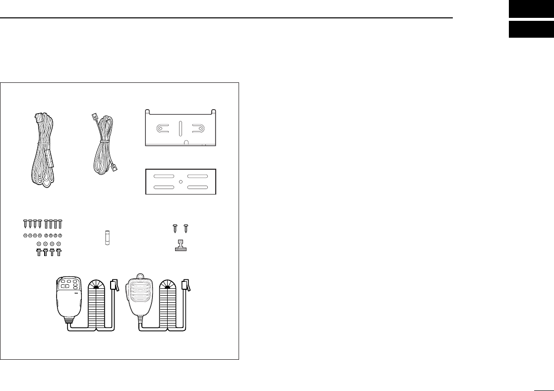
SUPPLIED ACCESSORIES
The transceiver comes with the following accessories. Qty.
qDC power cable (OPC-346) ........................................... 1
wRemote controller cable*1............................................... 1
eRemote controller mounting bracket (MB-73) ................. 1
rMain unit mounting bracket ............................................ 1
tMounting screws, nuts and washers ......................... 1 set
yFuse (FGB 20 A) ............................................................ 1
uRemote controller mounting screws and nut ............ 1 set
iMicrophone*2(HM-98/97/118) ........................................ 1
*1A ferrite core is attached at one end of the cable for the
U.S.A., Europe, Taiwan and Italy versions.
*2The microphones illustrated at left are the HM-98 and
HM-118. One of either the HM-98, HM-97 or HM-118/T/TA
microphone is supplied depending on version.
qe
r
w
ty u
i
HM-98 HM-118
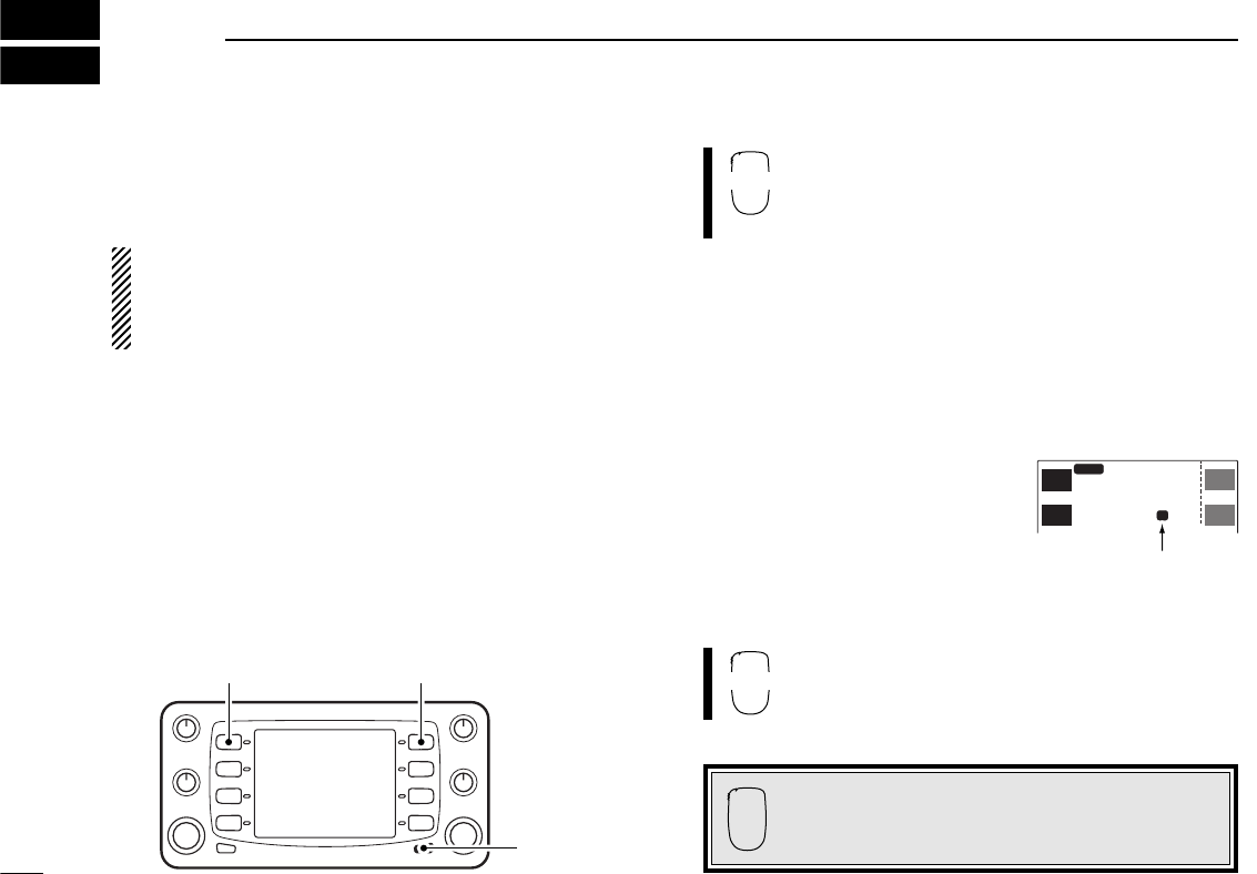
■Controller unit
2
2PANEL DESCRIPTION
MAIN SCP
SCP
TS
V/M
H
TS
V/M
H
SCN
M/C
SCN
M/C
LOW
MONI
LOW
MONI
TOT
RX
TX
MID-LO
MID-LO
SUB
MAIN
DUP SQL
TPRIO
DUP SQL
TPRIO
OFF
M
P
M
P
99
14 5
5.000
99
43 5
3.000
VOL VOL
SQL SQL
CHG/L POWER
MAIN
Function display (p. 4)
q
w
e
rt
y
u
o
!0!0
i

3
2
PANEL DESCRIPTION
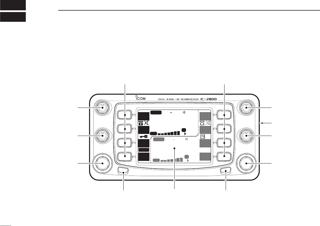
qVHF VOLUME CONTROL [VOL]
Adjusts the VHF audio level. (p. 23)
wVHF SQUELCH CONTROL [SQL]
➥Adjusts the VHF squelch level. (p. 23)
➥Depending on the set mode setting, the RF attenuator
is automatically activated when [SQL] is rotated clock-
wise past the 12 o’clock position. (pgs. 23, 66)
eVHF TUNING DIAL [DIAL]
Rotate [DIAL] to set operating frequencies, memory chan-
nels, set mode contents, etc. (p. 20)
rCHANGE/LOCK SWITCH [CHG/L]
➥Toggles the multi-function switch menu. (p. 6)
➥Push [CHG/L] for 2 sec. to toggle the lock function ON
and OFF. (p. 19)
tPOWER SWITCH [POWER]
Push for 2 sec. to toggle the transceiver power ON and
OFF. (p. 18)
yUHF TUNING DIAL [DIAL]
Rotate [DIAL] to set operating frequencies, memory chan-
nels, set mode contents, etc. (p. 20)
uUHF SQUELCH CONTROL [SQL]
➥Adjusts the UHF squelch level. (p. 23)
➥Depending on the set mode setting, the RF attenuator
is automatically activated when [SQL] is rotated clock-
wise past the 12 o’clock position. (pgs. 23, 66)
iVIDEO INPUT JACK [VIDEO IN]
Inputs an NTSC or PAL video signal depending on version.
(p. 73)
oUHF VOLUME CONTROL [VOL]
Adjusts the UHF audio level. (p. 23)
!0 MULTI-FUNCTION SWITCHES (pgs. 6, 7)
Push to select the function indicated in the right-hand or
left-hand LCD display of these switches.
•Left-hand switches are used for VHF band and right-hand
switches are used for UHF band.
•Functions vary depending on the operating condition.
4
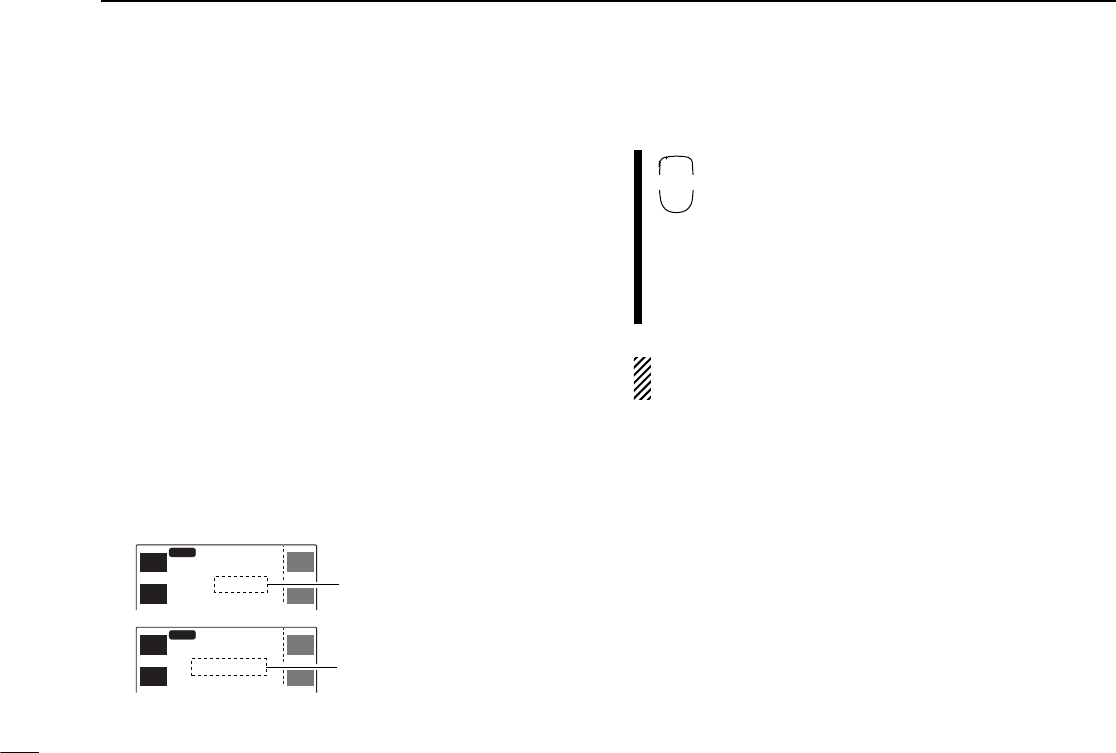
2PANEL DESCRIPTION
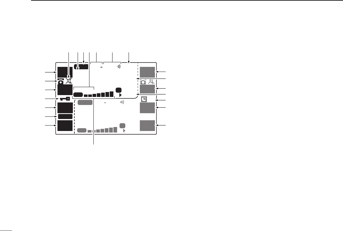
■Function display
qFUNCTION INDICATORS (pgs. 6, 7)
Indicate the functions assigned to the multi-function
switches at left.
wDTMF MEMORY ENCODER INDICATOR (p. 54)
Appears when the DTMF memory encoder is in use.
eLOCK INDICATOR (p. 19)
Appears when the lock function is in use.
rTIME-OUT TIMER INDICATOR (p. 63)
➥Appears when the time-out timer is activated.
➥Flashes when the time-out time elapses and the trans-
mission is terminated.
tS/RF INDICATOR
Shows the relative signal strength while receiving. Shows
the relative output power while transmitting. (pgs. 23, 24)
•“RX” appears when receiving a signal or when the squelch is
open.
•“TX” appears when transmitting.
yFUNCTION INDICATORS (pgs. 6, 7)
Indicate the functions assigned to the multi-function
switches at right.
uAUTO POWER-OFF INDICATOR (p. 64)
Appears when the auto power-off function is in use.
iMEMORY CHANNEL READOUT
Shows the memory or call channel number, etc.
➥“M” appears when a memory channel is selected. (p. 18)
➥“≈” appears when a selected memory channel is set as
a skip channel. (p. 46)
➥“P≈” appears when the memory channel frequency is
set as a skip frequency during scanning. (p. 46)
MAIN MAIN
SCP
SCP
V/M
H
TS
V/M
H
TS
M/C
SCN
M/C
SCN
MONI
LOW
MONI
LOW
TOT
RX
TX
MID-LO
MID-LO
SUB
MAIN
AM
DUP SQL
TPRIO
DUP SQL
TPRIO
OFF
M
P
M
P
99
43 5
3.000
99
14 5
5.000
q
q
q
r
q
w
e
t
i
y
y
u
y
y
o
!0!1!2!3!4!5!6

5
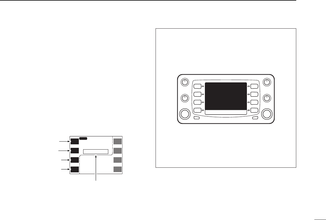
2
PANEL DESCRIPTION
oFREQUENCY READOUT
Shows the operating frequency, memory name, etc.
!0 PRIORITY WATCH INDICATOR (p. 48)
Appears when priority watch is in use.
!1 TONE INDICATORS (pgs. 26, 50, 52)
“T” appears when the subaudible tone encoder is in use;
“TSQLì” appears during pocket beep operation and
“T SQL” appears when the tone squelch function is acti-
vated.
!2 DUPLEX INDICATORS (p. 26)
Appear when semi-duplex operation (repeater operation)
is in use.
•“DUP–” appears when minus duplex is selected; “DUP” appears
when plus duplex is selected.
!3 OUTPUT POWER INDICATORS (p. 25)
➥“HI” appears when high output power is selected.
➥“MID-HI” appears when mid high output power is se-
lected
➥“MID-LO” appears when mid low output power is se-
lected
➥“LO” appears when low output power is selected
!4 MAIN BAND INDICATOR (p. 18)
➥“Q” appears above the frequency which is selected
as the main band.
➥“^” appears when the sub band access function is
in use.
•This function can be used via the HM-98 and HM-90.
!5 AM/FM NARROW MODE INDICATOR (p. 74)
➥“AM” appears when AM mode is selected.
•AM mode is available for the U.S.A. and S. America versions
only.
➥“NAR” appears when FM narrow mode is selected.
•FM narrow mode is available for the VHF band of the Europe
and Italy versions only.
!6 MUTE INDICATOR (pgs. 24, 65)
➥Both band’s indicators appear when the mute function is
in use.
•This function can be used via the HM-98 and HM-90.
➥Sub band’s indicator appears when the sub band mute
function is activated.
6
2PANEL DESCRIPTION
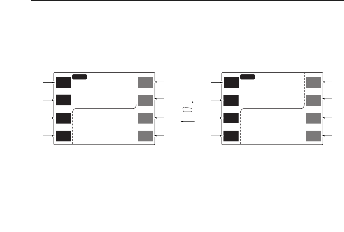
■Basic function menu
The multi-function switches have 2 main menus. Pushing
[CHG/L] toggles between the 2 multi-function switch menus.
Left-hand switches are used for VHF band and right-hand
switches are used for UHF band except iand o.
MAIN
SCP
MAIN
SCP
V/M
H
TS
V/M
H
TS
M/C
SCN
M/C
SCN
MONI
LOW
MONI
LOW
MID-LO
MID-LO
MAIN
43
3.000
12
14
5.000
12
MID-LO
MID-LO
MAIN
43
3.000
12
14
5.000
12
MAIN
EDIT EDIT
MAIN
S.MW
MW S.MW
MW
DTMF
TON
DUP TON
DUP
DISP
SET
CHG/L
q
w
e
rr
e
w
qt
y
u
io
u
y
t
qMAIN BAND/BAND SCOPE MENU [MAIN(SCP)]
➥Push to select the main band. (p. 18)
➥Push for 2 sec. to enter the band scope screen. (p. 47)
wVFO/MHz/TUNING STEP MENU [V/M
H
(TS)]
➥Push to select VFO mode or to select the MHz tuning
step while in VFO mode. (p. 20)
➥Push for 2 sec. to enter tuning step screen. (p. 21)
eMEMORY CHANNEL/CALL CHANNEL/SCAN MENU
[M/C(SCN)]
➥Push to select the memory mode or call channel. (pgs.
18, 38)
➥Push for 2 sec. to enter the scan screen. (p. 42)

7
2
PANEL DESCRIPTION
rMONITOR/LOW POWER MENU [MONI(LOW)]
➥Push to toggle the monitor function ON and OFF. (p. 24)
➥Push for 2 sec. to change the output power selection. (p.
25)
•Low (LO), mid-low (MID-LO), mid-high (MID-HI) and high (HI)
powers are available.
tMAIN BAND/MEMORY EDIT MENU [MAIN(EDIT)]
➥Push to select the main band. (p. 18)
➥Push for 2 sec. to enter the edit screen. (pgs. 29, 30, 37,
46, 51)
yTONE/DUPLEX MENU [TON(DUP)]
➥Push to activate the following functions in order.
•Subaudible tone encoder—“T” appears. (p. 26)
•Pocket beep—“T SQLì” appears. (p. 52)
•Tone squelch—“T SQL” appears. (p. 50)
•No tone operation—no indicator appears.
➥Push for 2 sec. to select semi-duplex or simplex opera-
tion. (p. 26)
•“DUP–” appears during minus duplex operation, “DUP” ap-
pears during plus duplex operation and no indicator appears
during simplex operation.
uSELECT MEMORY WRITE/MEMORY WRITE MENU
[S.MW(MW)]
➥Push to select the desired memory channel number to
be programmed. (p. 32)
➥Push for 2 sec. to program a memory channel or call
channel while in VFO mode. (p. 32)
➥Push for 2 sec. to transfer a memory channel, call chan-
nel or scratch pad memory contents into the VFO when
not in VFO mode. (p. 33)
iDTMF MENU [DTMF]
➥Push to toggle the DTMF memory ON and OFF. (p. 55)
➥Push for 2 sec. to enter the DTMF memory screen. (p.
54)
oDISPLAY/SET MODE MENU [DISP(SET)]
➥Push to enter the display set mode screen. (p. 68)
➥Push for 2 sec. to enter the set mode screen.
8
2PANEL DESCRIPTION
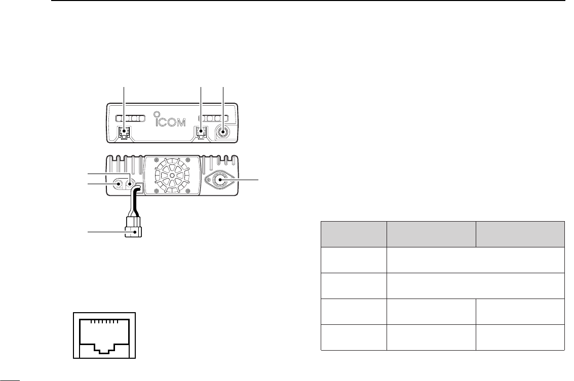
■Main unit
qMICROPHONE CONNECTOR [MIC]
Connects the supplied microphone.
wCONTROLLER CONNECTOR [CONTROLLER] (p. 16)
Connects the controller unit with the supplied cable.
eDATA CONNECTOR [DATA] (p. 70)
Connects a TNC (Terminal Node Controller), etc. for data
communications.
•See the information at right for details.
r144 MHz SPEAKER CONNECTOR [144 MHz SP]
Connects an 8 Ωspeaker, if desired.
t430(440) MHz SPEAKER CONNECTOR
[430(440) MHz SP]
Connects an 8 Ωspeaker, if desired.
DATA
MIC CONTROLLER
qwe
t
r
y
u
q+8 V DC output (Max. 10 mA)
wFrequency up/down
eHM-90/98 control input
rPTT
tMicrophone ground
yMicrophone input
uGround
iNo connection
➀➇
With no exter-
nal speakers
[144MHz SP]
only
[430(440) MHz
SP] only
2 external
speakers
VHF band audio UHF band audio
Connected
speaker
Internal speaker (mixed audio)
External speaker (mixed audio)
Internal speaker
External speaker via
[144MHz SP]
External speaker via
[430(440) MHz SP]
External speaker
yPOWER RECEPTACLE [DC13.8V] (pgs. 15, 16)
Accepts 13.8 V DC ±15% with the supplied DC power
cable.
•Current of 12 A or greater is required.
DO NOT use a cigarette lighter socket as a power
source when operating in a vehicle.The plug may cause
voltage drops and ignition noise may be superimposed
onto transmit or receive audio.
uANTENNA CONNECTOR [ANT]
Connects a 50 Ωantenna with a PL-259 connector and a
50 Ωcoaxial cable.
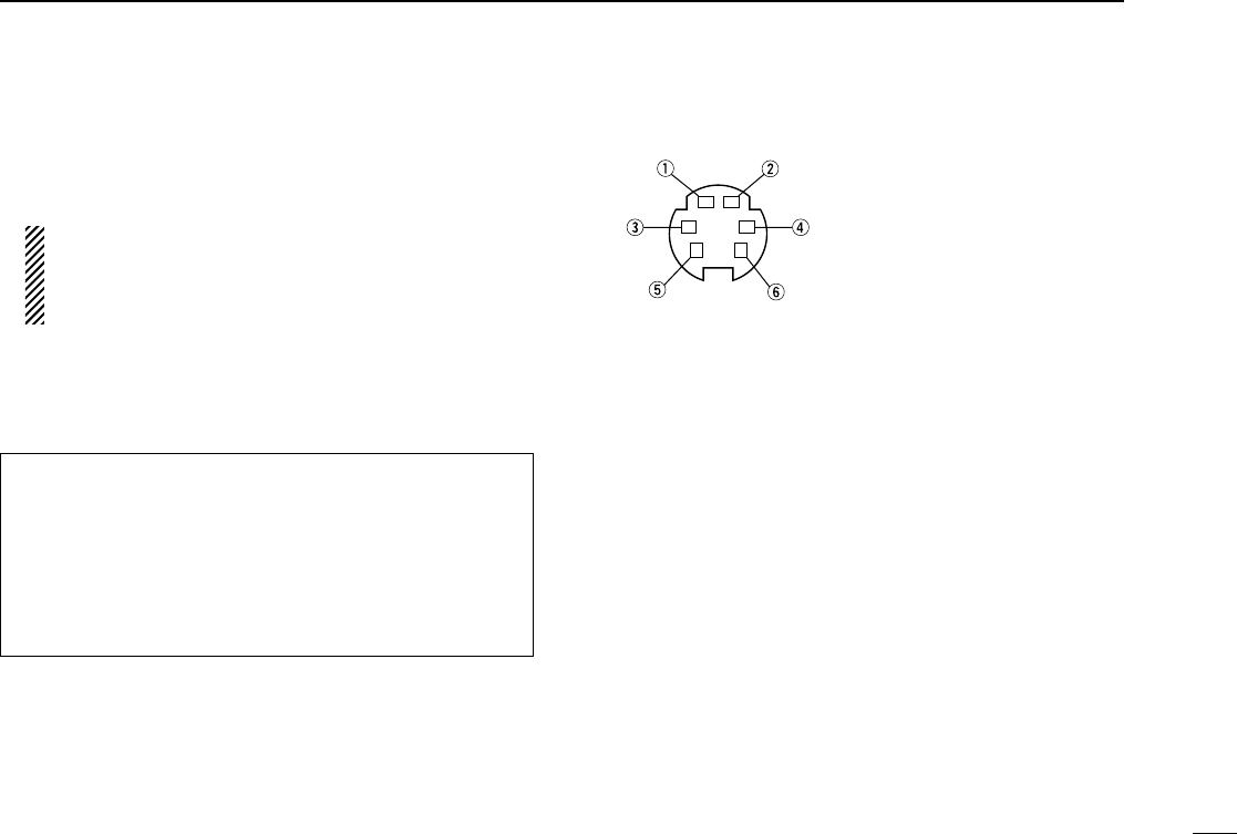
DDATA JACK PIN ASSIGNMENTS
qDATA IN
Input terminal for data transmit. See p. 70 for details on
how to toggle data speed between 1200 and 9600 bps.
wGND
Common ground for DATA IN, DATA OUT and AF OUT.
ePTTP
PTT terminal for packet operation only. Connect ground to
transmit data.
rDATA OUT
Data out terminal for 9600 bps operation only.
tAF OUT
Data out terminal for 1200 bps operation only.
yPSQL (squelch out)
Becomes high (+5V) when the transceiver receives a sig-
nal which opens the squelch.
•To avoid unnecessary TNC transmission, connect squelch to the
TNC to inhibit transmission when receiving signals.
•Keep audio output at a normal level, otherwise a “PSQL” signal
will not be output.
9
2
PANEL DESCRIPTION
qDATA IN (1200 bps: AFSK
9600 bps: G3RUH, GMSK)
wGND
ePTTP
rDATA OUT (9600 bps)
tAF OUT (1200 bps)
yPSQL
ANTENNA INFORMATION
For radio communications, the antenna is of critical impor-
tance, along with output power and sensitivity. The trans-
ceiver accepts a 50 Ωantenna and less than 1.5 : 1 of
Voltage Standing Wave Ratio (VSWR). High SWR values
not only may damage the transceiver but also lead to TVI or
BCI problems.
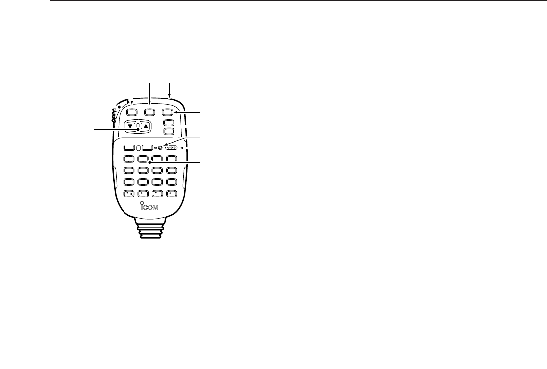
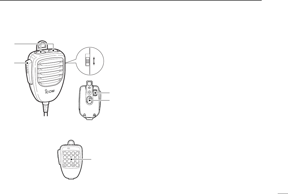
■HM-98 microphone*
qUP/DOWN SWITCHES [YY]/[ZZ]
➥Push either switch to change the operating frequency,
memory channel, set mode contents, etc. (p. 20)
➥Push either switch for 2 sec. to start scanning. (p. 43)
wPTT SWITCH
➥Push and hold to transmit; release to receive. (p. 24)
➥Toggles between transmitting and receiving while the
one-touch PTT function is in use. (p. 25)
eVFO SWITCH [VFO(LOCK)]
➥Push to select VFO mode. (p. 18)
➥Push for 2 sec. to toggle the lock function. (p. 19)
rMEMORY SWITCH [MR(CALL)]
➥Push to select memory mode.
➥Push for 2 sec. to select the call channel. (p. 38)
tACTIVITY INDICATOR
Lights red while a key is pushed; lights green while the
one-touch PTT function is in use.
yBAND SWITCH [BAND(SUB)] (p.18)
➥Push to toggle the operating band or set the sub band
as the main band.
➥Push for 2 sec. to toggle the sub band access function.
uFUNCTION SWITCHES [F-1]/[F-2] (p.67)
Assign your desired key function from the front panel
switches.
•Default settings are [VHF M/C] for [F-1] and [UHF M/C] for [F-2].
iFUNCTION INDICATOR
➥Lights orange while [FUNC] is activated—indicates the
secondary function of switches can be accessed.
➥Lights green when [DTMF-S] is activated—DTMF sig-
nals can be transmitted with the keypad. (p. 55)
oKEYPAD
Used for controlling the transceiver, transmitting DTMF sig-
nals, etc. See the following 2 pages for details.
10
2PANEL DESCRIPTION
LOCK
VFO
CALL
MR
SUB
BAND
MW
FUNC
A
CLR
D-OFF
B
SET
PTT-M
3
PRIO
DTMF
6
LOW
AFC-OFF
2
SCAN
CSQL
5
MID
AFC
1
MONI
PGR
4
HIGH
T-OFF
C
ENT
TSQL
9
SIMP
16
KEY LOCK
#
TSQLS
8
DUP+
TONE-2
0
TONE
7
DUP–
TONE-1
F-2
F-1
DTMF-S
MUTE
D
SQLSQLVOLVOL
Mic element
q
w
er t
y
u
i
o
*Some versions are
supplied with the
HM-97/118 instead.

11
2
PANEL DESCRIPTION
KEY FUNCTION SECONDARY FUNCTION (after )
FUNC
OTHER FUNCTIONS
AFC
1
MONI
Toggles between opening and closing the
operating band’s squelch. (p. 24) No secondary function.
After :
Transmit the appropriate
DTMF code or push [0]
to [9], [A] to [D] to trans-
mit the DTMF memory
contents when the
DTMF memory encoder
is activated. (p. 54)
DTMF-S
AFC-OFF
2
SCAN
Starts and stops scanning. (p. 42) No secondary function.
PTT-M
3
PRIO Starts and stops priority watch. (p. 48) Turns the one-touch PTT function ON and
OFF. (p. 25)
PGR
4
HIGH Selects high output power. (p. 25) No secondary function.
CSQL
5
MID Selects mid-high output power. (p. 25) No secondary function.
DTMF
6
LOW Selects low output power. (p. 25) Turns the DTMF memory encoder function
ON. (p. 54)
TONE
7
DUP– Selects –duplex. (p. 27) Turns the subaudible tone encoder ON.
(p. 27)
TSQLS
8
DUP+ Selects +duplex. (p. 27) Turns the pocket beep function ON. (p. 52)
TSQL
9
SIMP Selects simplex. (p. 27) Turns the tone squelch function ON. (p. 50)
TONE-2
0
VOL
Increases the audio output. (p. 23)
•The [VOL] controls on the controller unit have
priority when rotated.
While being pushed, transmits a 1750 Hz
tone. (p. 28)

12
2PANEL DESCRIPTION
KEY FUNCTION SECONDARY FUNCTION (after )
FUNC
OTHER FUNCTIONS
MW
A
CLR
•Clears a digit before entry. (p. 22)
•Cancels the monitor, scan, priority watch,
DTMF memory, mute function or set
mode condition. (pgs. 24, 42, 48, 54)
•Writes the VFO contents into the memory
channel or call channel. (pgs. 34, 39)
•Advances the memory channel number
when continuously pushed after program-
ming is completed. (p. 34) After :
Transmit the appropriate
DTMF code or push [0]
to [9], [A] to [D] to trans-
mit the DTMF memory
contents when the
DTMF memory encoder
is activated. (p. 54)
DTMF-S
D-OFF
B
SET
Enters set mode and decreases the set
mode selection order. DTMF memory OFF.
16
KEY LOCK
#
SQL
T-OFF
C
ENT
•Sets the keypad for numeral input.(p. 22)
•Advances the set mode selection order
after entering set mode.
Turns the subaudible tone encoder, pocket
beep or tone squelch OFF. (pgs. 27, 50, 52)
Decreases the squelch level. (p. 23)
•The [SQL] controls on the controller unit have
priority when rotated.
MUTE
D
SQL
Increases the squelch level. (p. 23)
•The [SQL] controls on the controller unit have
priority when rotated.
Mutes both band’s audio. (p. 24)
•Mute function is released when any operation is
performed.
Locks the digit keys on the keypad (including
the A–D, # and Mkeys). (p. 19)
TONE-1
M
VOL
Decreases the audio output. (p. 23)
•The [VOL] controls on the controller unit have
priority when rotated.
Sends a 1750 Hz tone signal for 0.5 sec.
(p. 28)
After :
Transmit the appropriate
DTMF code. (p. 54)
DTMF
13
2
PANEL DESCRIPTION
■HM-97/118 microphone
qPTT SWITCH
Push and hold to transmit; release to receive. (p. 24)
wUP/DOWN SWITCHES [UP]/[DN]
➥Push either switch to change the operating frequency,
memory channel, set mode contents, etc. (p. 20)
➥Push either switch for 2 sec. to start scanning. (p. 42)
➥Activate a function programmed in set mode. (p. 68)
eLOCK SWITCH
Locks the [UP]/[DN] keys on the microphone.
rTONE SWITCH (HM-97 only)
Push to transmit a 1750 Hz tone call signal. (p. 28)
tDTMF KEYPAD (HM-118T/TA only)
Used for transmitting DTMF signals.
1 2 3 A
4 5 6 B
7 8 9 C
0 D
HM-97HM-118
HM-118T/TA
ON
OFF
q
w
e
e
r
t
14
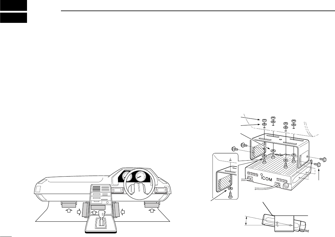
3INSTALLATION
■Location
Select a location which can support the weight of the trans-
ceiver and does not interfere with driving in any way. We rec-
ommend the locations shown in the diagram below.
NEVER place the transceiver or remote controller where nor-
mal operation of the vehicle may be hindered or where it
could cause bodily injury.
NEVER place the transceiver or remote controller where air
bag deployment may be obstructed.
DO NOT place the transceiver or remote controller where hot
or cold air blows directly onto it.
AVOID placing the transceiver or remote controller in direct
sunlight.
•EXAMPLE INSTALLATION LOCATIONS
■Mounting with the mounting
bracket
qDrill 4 holes where the mounting bracket is to be installed.
•Approx. 5.5–6 mm (3⁄16˝) when using nuts; approx. 2–3 mm (1⁄16˝)
when using self-tapping screws.
wInsert the supplied screws, nuts and washers through the
mounting bracket and tighten.
eAdjust the angle, if desired.
Nut
Spring washer
When using
self-tapping
screws
Spring
washer
25°
Mounting
nut
Mounting
bracket
Flat washer
15
3
INSTALLATION
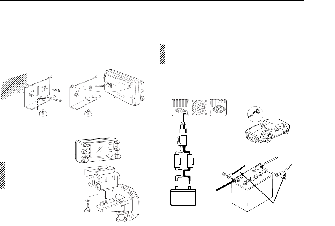
■Mounting the remote
controller
Install the nut before attaching the bracket to the wall, etc.
DWhen using an
optional MB-65
The supplied remote con-
troller bracket is not nec-
essary when using the
optional MB-65.
■Battery connection
NEVER connect the transceiver directly to a 24 V battery.
DO NOT use the cigarette lighter socket for power con-
nections.
Attach a rubber grommet when passing the DC power cable
through a metal plate to prevent short circuits.
•See p. 74 for fuse replacement.
Nut Nut
MB-65
Remote
controller
12 V
Fuses
20 A + red
+ red
Grommet
_ black
_ black
Supplied
DC power cable
16
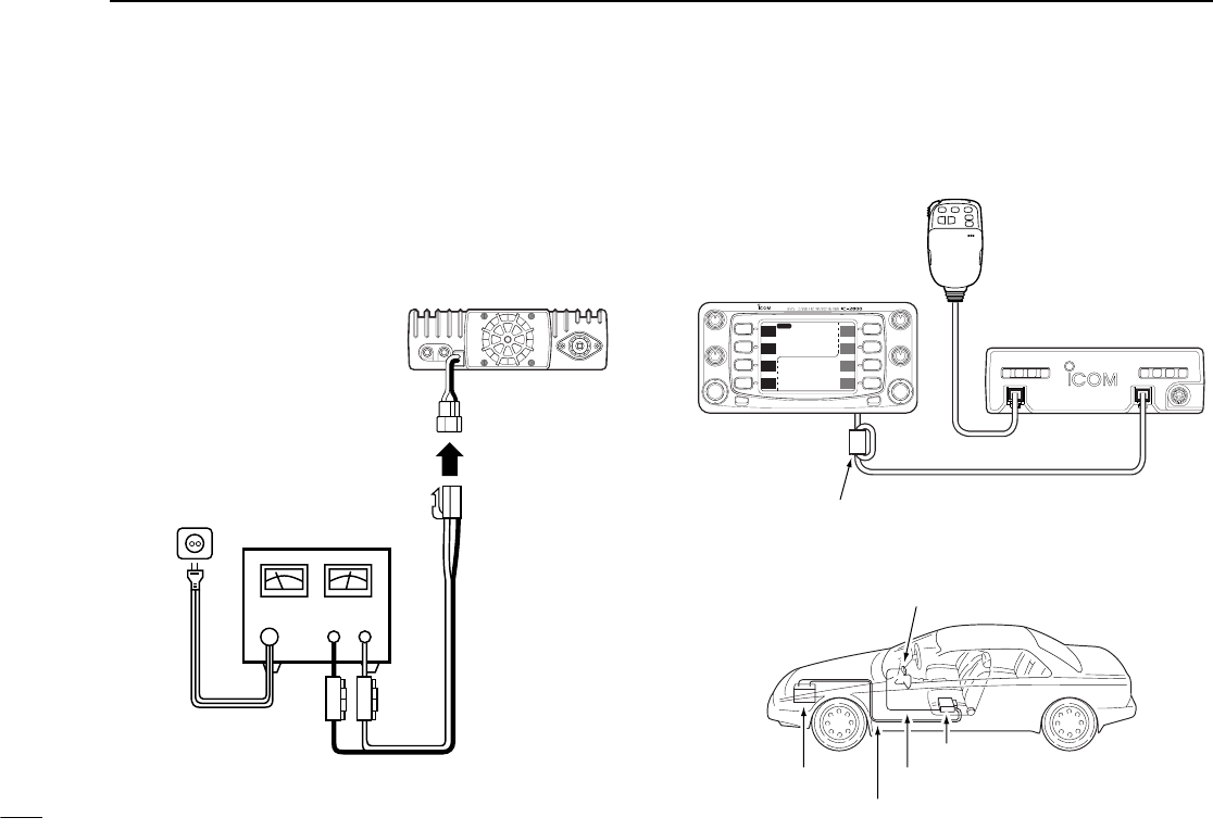
3INSTALLATION
■DC power supply connection
Use a 13.8 V DC power supply with more than 12 A capacity.
Make sure the ground terminal of the DC power supply is
grounded.
•See p. 74 for fuse replacement.
■Cable connection
Connect the cable as shown below.
DC power
supply 13.8 V
to an
AC
outlet
Fuses
20 A
+ red
+_
_ black
Battery
Remote controller
Remote controller cable
Power cable
Main unit
DATA
MIC CONTROLLER
MAIN MAIN
SCP
SCP
V/M
H
TS
V/M
H
TS
M/C
SCN
M/C
SCN
MONI
LOW
MONI
LOW
HI
HI
MAIN
1
14
5.000
1
43
3.000
VOL VOL
SQL SQL
CHG/L POWER
Remote controller
Speaker is
included in the
remote controller
Connect the end with the
ferrite core to the controller
(where applicable)
Supplied remote controller
cable (3.5 m, 11.5 ft)
IC-2800 main unit
■Antenna installation
DAntenna location
To obtain maximum performance from the transceiver, select
a high-quality antenna and mount it in a good location. A non-
radial antenna should be used when using a magnetic mount.
DAntenna connector
The antenna uses a PL-259 connector.
17
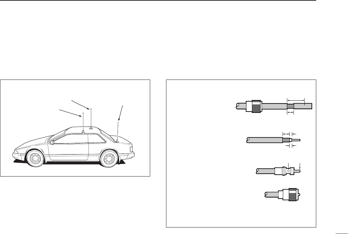
3
INSTALLATION
Roof-mount antenna
(Drill a hole or use a magnetic mount.) Trunk-mount
antenna
Gutter-mount antenna
•PL-259 CONNECTOR
qSlide the coupling ring
down. Strip the cable
jacket and soft solder.
wStrip the cable as
shown at right. Soft
solder the center con-
ductor.
eSlide the connector
body on and solder it.
rScrew the coupling
ring onto the connec-
tor body.
(10 mm≈3⁄8in)
30 mm
10 mm (soft solder)
10 mm
1–2 mm
solder solder
Soft
solder
Coupling ring
18
4FREQUENCY SETTING
■Preparation
DTurning power ON/OFF
Before operating the transceiver for the first time it’s a good
idea to reset the transceiver’s CPU.This will ensure that all
transceiver settings are at their defaults. See p. 75 for CPU
resetting details.
➥Push [POWER] for 2 sec. to turn power ON or OFF.
DOperating band
The transceiver can receive 144 MHz and 430(440) MHz
band signals simultaneously. To activate all functions or to
change frequency via the microphone, you must designate
one band as the main band. The transceiver can transmit a
signal on the main band only.
➥Push either [MAIN] to select the desired transmit band.
•“Q” indicator shows the selected band as the main band.
➥Push [BAND] to select the desired operating
band.
•“Q” indicator shows the selected band as the
main band.
DVFO and memory modes
The transceiver has 2 basic operating modes: VFO mode and
memory mode. Select VFO mode first to set an operating fre-
quency.
➥Push [V/M
H
] to select VFO mode when the transceiver is
not in VFO mode.
•If VFO mode is already selected,
the digits below 100* kHz disap-
pear. In this case, push [V/M
H
]
again (or push twice or 3 times de-
pending on version).
*The digits below 1 or 10 MHz dis-
appear for some versions.
➥Push [VFO] to select VFO mode.
➥Push [MR] to select memory mode.
VFO
BAND
Note that in this manual, sections beginning with
a microphone icon (as above), designate opera-
tion via the HM-98 microphone.
[POWER]
[MAIN][MAIN]
MAIN
SCP
MAIN
SCP
V/M
H
TS
V/M
H
TS
MID-LO
MAIN
M
12
14
5.000
“M” appears in
memory mode.

■Lock functions
To prevent accidental frequency changes and unnecessary
function access, use the lock function. The transceiver and
HM-98 have 2 different lock functions.
DFrequency lock
This function locks the tuning dials and switches electronically
and also locks the microphone switches.
➥Push [CHG/L] for 2 sec. to toggle the frequency lock func-
tion ON and OFF.
•[CHG/L], [MAIN], [MONI], [VOL], [SQL], [PTT] and [BAND] can
be used while the frequency lock function is in use. Also,
TONE-1, TONE-2, DTMF tones or DTMF memory contents can
be transmitted from the HM-98 microphone.
➥Push [(VFO)LOCK] for 2 sec. to toggle the func-
tion ON and OFF.
DMicrophone keypad lock
This function locks the HM-98 microphone keypad.
➥Push [FUNC] then [16KEYLOCK] to tog-
gle the microphone keypad lock function
ON and OFF.
•[PTT] and the 7 keys on the upper half of the
microphone can be used.
•All switches on the transceiver can be used.
•The keypad lock function is released when the
transceiver power is turned OFF then ON
again.
MID-LO
MAIN
43
3.000
12
14
5.000
12
SCP
MAIN
TS
V/M
H
SCN
M/C
LOW
MONI
SCP
MAIN
TS
V/M
H
SCN
M/C
LOW
MONI
MID-LO
“ ” appears when the lock function is in use.
19
4
FREQUENCY SETTING
LOCK
16 KEY LOCK
#
20
4FREQUENCY SETTING
■Using the tuning dial
qSelect VFO mode with the desired band’s [V/M
H
].
•Push [CHG/L] if [V/M
H
] is not displayed.
wRotate desired band’s [DIAL] to change the frequency.
•The frequency changes according to the selected tuning steps.
See the next page for selecting the tuning step.
D1 MHz tuning step
Push the selected band’s [V/M
H
] to select 1 MHz tuning step.
Push [V/M
H
] again to return to the previous tuning step.
D10 MHz and 1 MHz tuning steps
Push the selected band’s [V/M
H
] once or twice to select 10
MHz or 1 MHz tuning step, respectively. Push [V/M
H
] once or
twice to return to the previous tuning step.
Some versions do not have the 10 MHz tuning step.
■Using the [Y]/[Z] keys
qPush [BAND] to select the desired band.
wPush [VFO] to select the VFO mode.
ePush [Y] or [Z] to select the desired frequency.
•The frequency changes according to the selected
tuning steps. (p. 21)
•Pushing [Y] or [Z] for more than 0.5 sec. activates
a scan. If this happens, push [Y] or [Z] again to
cancel the scan.
1 MHz or 10 MHz steps cannot be used via the [Y]/[Z]
keys.
MAIN
SCP
MAIN
SCP
V/M
H
TS
V/M
H
TS
MAIN
12
14
5.___
MAIN
SCP
MAIN
SCP
V/M
H
TS
V/M
H
TS
MAIN
12
14
_.___
While 1 MHz tuning step is
selected, the digits below
100 kHz disappear.
While 10 MHz tuning step is
selected, the digits below
1 MHz disappear.
Y Z
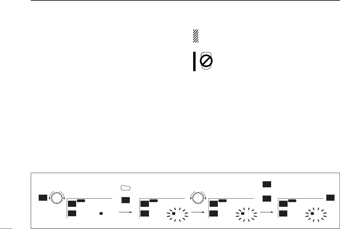
■Setting a tuning step
Tuning steps can be selected for each band. This transceiver
has 8 tuning steps as follows:
•5 kHz •10 kHz •12.5 kHz •15 kHz •20 kHz
•25 kHz •30 kHz •50 kHz
qSelect VFO mode with the desired band’s [V/M
H
].
•Push [CHG/L] if [V/M
H
] is not displayed.
wPush [(V/M
H
)TS] for 2 sec. to enter tuning step screen.
eRotate desired band’s [DIAL] to select the desired tuning
step.
•Pushing [5], [20] or [25] also selects 5, 20 or 25 kHz tuning step.
rPush [í] to return to normal operation.
21
4
FREQUENCY SETTING
MAIN
43
3.000
14
5.000
12
í
5
20
25
SCP
MAIN
TS
V/MH
SCN
M/C
LOW
MONI
TS = 5.0kTS = 5.0k
Return to previous menu
Shows 5 kHz tuning step is selected.
Select 5 kHz tuning step
Select 20 kHz tuning step
Select 25 kHz tuning step
•Cloning mode information
The information in the transceiver, such as memory chan-
nels, memory names, etc. can be programmed using a PC.
The transceiver displays the following information when the
transceiver enters cloning mode for programming.
In the cloning mode, the [POWER] switch does not func-
tion. Push the [UP]/[DN] or [Y]/[Z] on the microphone to
return to the normal operating condition.
Push mic UP/DN to EXIT.
CLONE
■Using the keypad
The frequency can be directly set via numeral keys
on the HM-98 microphone.
qPush [BAND] to select the desired operating band.
wPush [VFO] to select VFO mode, if necessary.
ePush [ENT] to activate the keypad for digit input.
rPush 6 keys to input a frequency.
•When a digit is mistakenly input, push [ENT] to clear the input,
then repeat input from the 1st digit.
•Pushing [CLR] clears input digits and retrieves the frequency.
tPush [Y] or [Z] to make adjustments below the 10 kHz
digit, if desired.
22
4FREQUENCY SETTING
ENT
C
[EXAMPLE]: Setting the frequency to 145.3625 MHz.
MAIN
12
14
5.000
MID-LO
SCP
MAIN
TS
V/M
H
SCP
MAIN
TS
V/M
H
MAIN
12
5.
MID-LO
SCP
MAIN
TS
V/M
H
SCP
MAIN
TS
V/M
H
MAIN
12
14
5.36
MID-LO
SCP
MAIN
TS
V/M
H
SCP
MAIN
TS
V/M
H
MAIN
12
14
5.362
MID-LO
SCP
MAIN
TS
V/M
H
SCP
MAIN
TS
V/M
H
5
C
ENT
BAND
VFO 3
PRIO
5
MID
1
MONI 4
HIGH 6
LOW 2
SCAN
■Receiving
qPush [POWER] for 2 sec. to turn power ON.
wSet the audio level.
➥Push the desired band’s [MONI] to open the squelch.
•Push [CHG/L] if [MONI] is not displayed.
➥Rotate the desired band’s [VOL] control to adjust the
audio output level.
➥Push [MONI] again to close the squelch.
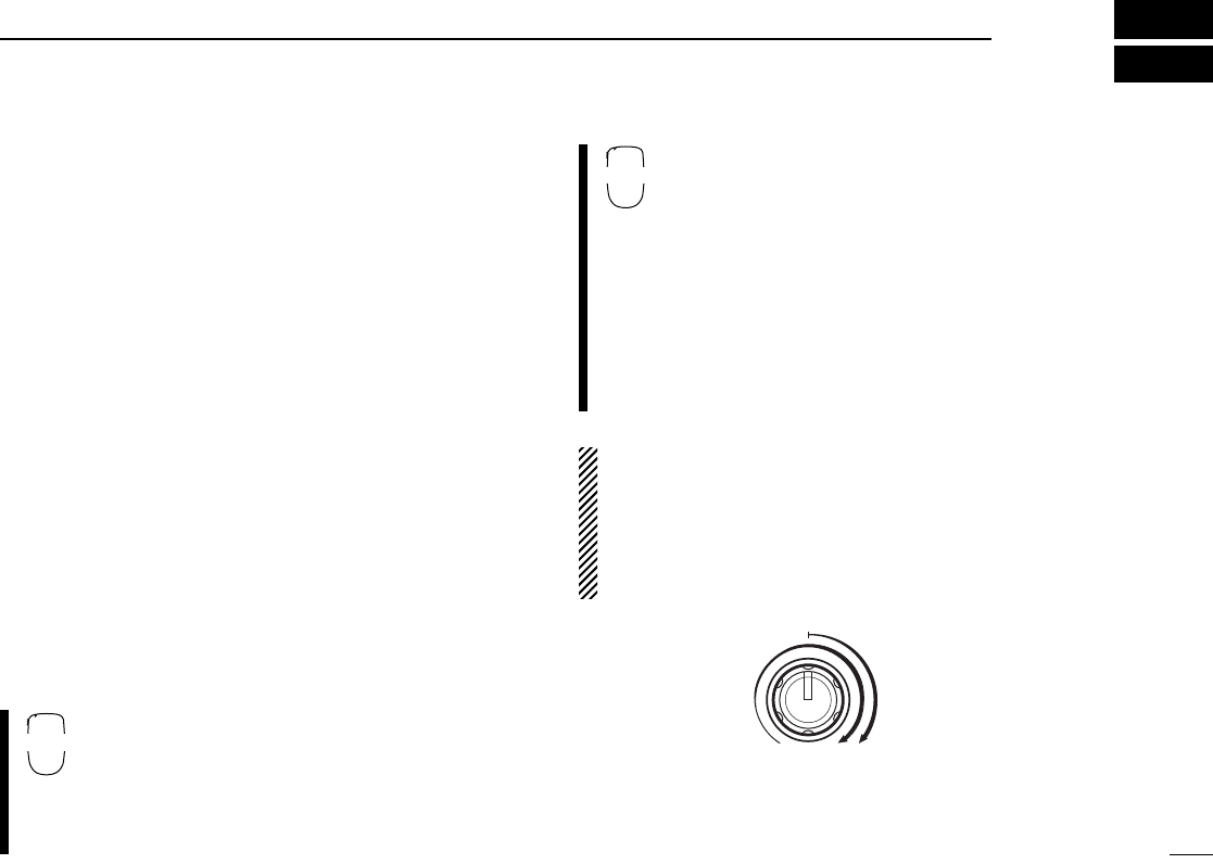
eSet the squelch level.
➥Rotate the desired band’s [SQL] fully counterclockwise
in advance.
➥Rotate [SQL] clockwise until the noise just disappears.
➥When interference is received, rotate [SQL] clockwise
again for attenuator operation.
•Turn the automatic RF attenuator ON in advance. (p. 66)
rSet the operating frequency. (p. 20)
tWhen receiving a signal on the set frequency, squelch
opens and the transceiver emits audio.
•“RX” appears and the S/RF indicator shows the relative signal
strength for the received signal.
qPush [POWER] for 2 sec. to turn power ON.
wSelect the desired band with [BAND].
eSet the audio level.
➥Push [qMONI] to open the squelch.
➥Push [VOLY] or [VOLZ] to adjust the audio
output level.
•Volume level appears while setting.
➥Push [qMONI] again to close the squelch.
rSet the squelch level.
➥Push [SQLY] or [SQLZ] to set the squelch
to the point where noise just disappears.
•Squelch level appears while setting.
tSet the operating frequency. (p. 22)
yWhen receiving a signal on the set frequency,
squelch opens and the transceiver emits audio.
•“RX” appears and the S/RF indicator shows the rel-
ative signal strength for the received signal.
RF attenuator:
The transceiver has an RF attenuator re-
lated to the [SQL] setting. The attenuator is automatically
activated when [SQL] is rotated clockwise past the 12 o’-
clock position. Approx. 10 dB attenuation is obtained at full
rotation. Turn the automatic RF attenuator ON in advance
in set mode. (p. 66)
23
5
BASIC OPERATION
RF attenuatorSquelch
range
0 dB
10 dB
SQL
Y Z
BAND

24
5BASIC OPERATION
■Monitor function
This function is used to listen to weak signals without disturb-
ing the squelch setting or to open the squelch manually even
when mute functions such as the tone squelch are in use.
➥Push the desired band’s [MONI] to toggle the monitor func-
tion ON and OFF.
•While duplex is ON for repeater operation, the transmitting fre-
quency can be monitored with [MONI].
Push [qMONI] to toggle the monitor function ON
and OFF.
■Audio mute function
This function temporarily mutes the audio without disturbing
the volume setting.
qPush [FUNC] then [HMUTE] to mute audio sig-
nals.
•“ ” appears.
wPush [ECLR] (or any other key) to cancel the
function.
•“ ” disappears.
■Transmitting
CAUTION: Transmitting without an antenna may
damage the transceiver.
To prevent interference, listen on the frequency before
transmitting by pushing [MONI] or [qMONI] on the HM-98
microphone.
qSelect the desired band with the desired band’s [MAIN] or
[BAND] on the HM-98 microphone.
wSet the operating frequency.
•Select output power if desired. See the next section for details.
ePush and hold [PTT] to transmit.
•“TX” appears.
•The S/RF indicator shows the output power selection.
•The operating frequency, etc. is automatically programmed into a
scratch pad memory. See p. 40 for details.
•A one-touch PTT function is available. See p. 25 for details.
rSpeak into the microphone using your normal voice level.
•DO NOT hold the microphone too close to your mouth or speak
too loudly. This may distort the signal.
tRelease [PTT] to return to receive.
MONI
1
MUTE
D
25
5
BASIC OPERATION
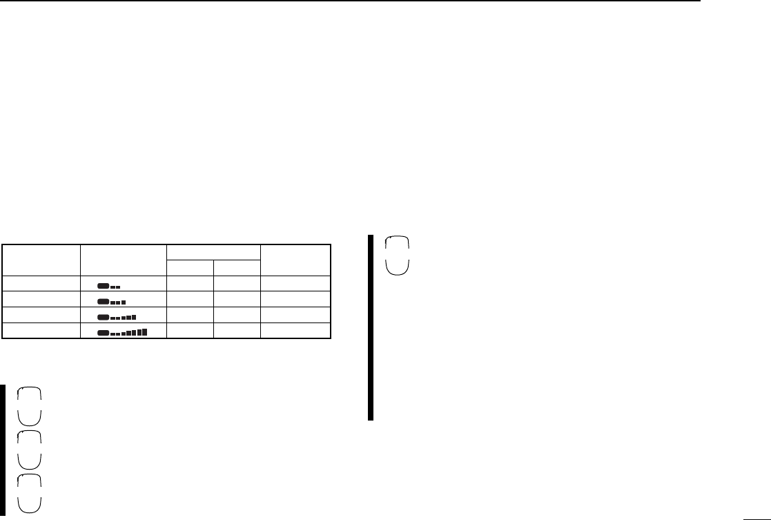
■Selecting output power
The transceiver has 4 output power levels to suit your operat-
ing requirements. Low output powers during short-distance
communications may reduce the possibility of interference to
other stations and will reduce current consumption.
➥Push the desired band’s [(MONI) LOW] for 2 sec. one or
more times to select the output power.
•Push [CHG/L] if [MONI(LOW)] is not displayed.
•The output power can be changed while transmitting.
The microphone can also be used to select output power.
qPush [BAND] to select the desired band.
wPush [rHIGH] for high output power; [tMID]
for mid-high output power; and [yLOW] for low
output power.
•The output power CANNOT be changed via the mi-
crophone while transmitting.
■One-touch PTT function
The PTT switch can be operated as a one-touch PTT switch
(each push toggles transmit/receive). Using this function you
can transmit without pushing and holding the PTT switch.
To prevent accidental, continuous transmissions with this
function, the transceiver has a time-out timer. See p. 63 for
details.
qPush [FUNC] then [ePTT-M] to turn the one-
touch PTT function ON.
•The activity indicator lights green.
wPush [PTT] to transmit and push again to re-
ceive.
•Two beeps sound when transmission is started and
a long beep sounds when returning to receive.
•“TX” flashes when transmitting with the one-touch
PTT function.
ePush [FUNC] then [ePTT-M] to turn the one-
touch PTT function OFF.
•The activity indicator goes out.
Power
selection S/RF indicator Output power Taiwan
version only
LOW
MID LOW
MID HIGH
HIGH
05 W
10 W
20 W
50 W
05 W
10 W
20 W
35 W
05 W
10 W
15 W
25 W
TX
LO
TX
MID-LO
TX
MID-HI
TX
HI
VHF UHF
HIGH
4
MID
5
LOW
6
PTT-M
B
■Accessing a repeater
When using a repeater, the transmit frequency is shifted from
the receive frequency by the offset frequency. (p. 30) It is con-
venient to program repeater information into memory chan-
nels. (p. 32)
qSelect the desired band with the desired band’s [MAIN].
wSet the receive frequency (repeater output frequency).
(pgs. 20)
ePush the desired band’s [(TON)DUP] for 2 sec., one or
more times, to select minus duplex or plus duplex.
•Push [CHG/L] if [(TON)DUP] is not displayed.
•“DUP–” or “DUP” appears to indicate the transmit frequency for
minus shift or plus shift, respectively.
•When the auto repeater function is in use (U.S.A. and Korea ver-
sions only), this selection and step rare not necessary. (p. 31)
rPush the desired band’s [TON] one or more times to turn
ON the subaudible tone encoder, according to repeater re-
quirements.
•Refer to p. 29 for tone frequency settings.
•When the repeater requires a different tone system, see the next
page.
tPush and hold [PTT] to transmit.
•The displayed frequency automatically changes to the transmit
frequency (repeater input frequency).
•The operating condition is automatically programmed into a
scratch pad memory. See p. 40 for details.
•If “OFF” appears, check the offset frequency. (p. 30)
yRelease [PTT] to receive.
uPush [MONI] to check whether the other station’s transmit
signal can be received directly.
•Push [CHG/L] if [MONI] is not displayed.
iTo return to simplex operation, push [(TON)DUP] for 2 sec.,
once or twice, to clear the “DUP” indicator.
oTo turn OFF the subaudible tone encoder, push [TON] one
or more times until no tone indicators appear.
26
6REPEATER OPERATION
MID-LO
MAIN
12
14
5.000
DUP
MAIN
EDIT EDIT
MAIN
TON
DUP TON
DUP
“DUP–” indicates minus duplex.
MID-LO
MAIN
12
14
5.000
DUP T
MAIN
EDIT EDIT
MAIN
TON
DUP TON
DUP
“T” indicates tone encoder is ON.
MID-LO
MAIN
12
14
5.000
MAIN
EDIT EDIT
MAIN
TON
DUP TON
DUP

27
6
REPEATER OPERATION
qSelect the desired band with [BAND].
wSet the receive frequency (repeater output fre-
quency).
ePush [uDUP–] to select –duplex; push
[iDUP+] for +duplex.
rPush [FUNC] then [uTONE] to turn ON the
subaudible tone encoder according to repeater
requirements.
•Refer to p. 29 for tone frequency setting.
•When the repeater requires a different tone system,
see p. 29.
tPush and hold [PTT] to transmit.
yPush [qMONI] to check whether the other sta-
tion’s signal can be received directly.
uRelease [PTT] to receive.
iTo return to simplex operation, push [oSIMP].
oTo turn OFF the subaudible tone encoder, push
[FUNC], then [GT-OFF].
➲
CONVENIENT
Tone scan function:
When you don’t know the subaudible
tone used for a repeater, the tone scan is convenient for de-
tecting the tone frequency.
qPush the desired band’s [(M/C)SCN] for 2 sec. to enter scan
screen.
•Push [CHG/L] if [(M/C)SCN] is not displayed.
wPush [TON] to start tone scan. Push [í] for 2 sec. to exit
scan screen. See p. 53 for more information.
DDTMF tones
qPush [BAND] to select the desired band.
wPush [DTMF-S], then push the keys of the de-
sired DTMF digits.
•The function indicator lights green.
•0–9, A–D, M(E) and #(F) are available.
•Cancel the DTMF memory encoder in advance, if
necessary. (p. 54)
•Push [DTMF-S] again to return the keypad to nor-
mal function control.
•The transceiver has 14 DTMF memory channels
(D0–D9, DA–DD) for auto patch operation. (p. 54)
DTMF-S
DUP–
7
DUP+
8
SIMP
9

28
6REPEATER OPERATION
■1750 Hz tone
A 1750 Hz tone is required to access most European re-
peaters.The microphone has 1750 Hz tone capability.
DUsing the HM-98 microphone
qPush [BAND] to select the desired band.
wPush [FUNC].
•The mode indicator lights orange.
ePush [BTONE-1] to transmit a 1750 Hz tone
call signal for 0.5 sec.; push and hold [p
TONE-2] to transmit a 1750 Hz tone call signal
for an arbitrary period.
•The mode indicator goes out automatically.
•The optional HM-90 also has 1750 Hz tone capabil-
ity.
DUsing the HM-97 microphone
➥Push [TONE] on the microphone rear panel to transmit a
1750 Hz tone.
TONE-1
M
TONE-2
0
[TONE]
29
6
REPEATER OPERATION
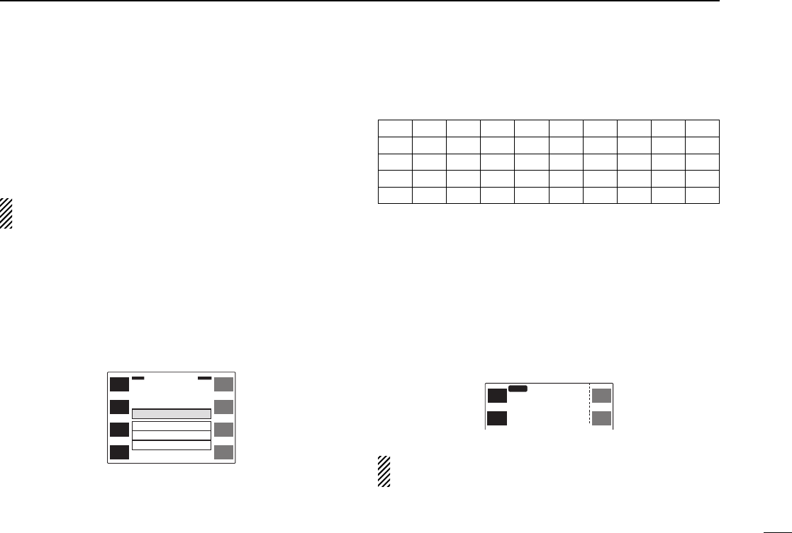
■Subaudible tone
(encoder function)
Some repeaters require subaudible tones to be accessed.
Subaudible tones are superimposed over your normal signal
and must be set in advance.
Each operating band and each memory channel have inde-
pendent settings.
qSelect the mode/channel you wish to set the subaudible
tone encoder frequency to, such as VFO mode or mem-
ory/call channel.
wPush the desired band’s [(MAIN)EDIT] for 2 sec. to enter the
edit screen.
•Push [CHG/L] if [(MAIN)EDIT] is not displayed.
ePush [Y] or [Z] to select the ‘R-Tone’ item.
•Left-hand tuning dial can also select the item.
rRotate the right-hand tuning dial to select the desired fre-
quency.
•The subaudible tone encoder frequency is set temporarily. Push
[MW] for 2 sec. to store the tone frequency permanently.
•The color of the frequency indication changes when the setting is
different from the memory or call channel contents.
tIf you want to set other channels, push [CH] then rotate the
right-hand tuning dial. Repeat eand rto select the de-
sired frequency.
yPush [ï] to exit the edit screen.
The subaudible tone encoder frequency can be set in a
memory channel temporarily. However, the set contents
are cleared once the other memory/call channel is se-
lected. To store the tone frequency permanently, push
[MW] for 2 sec. at step rto overwrite the information.
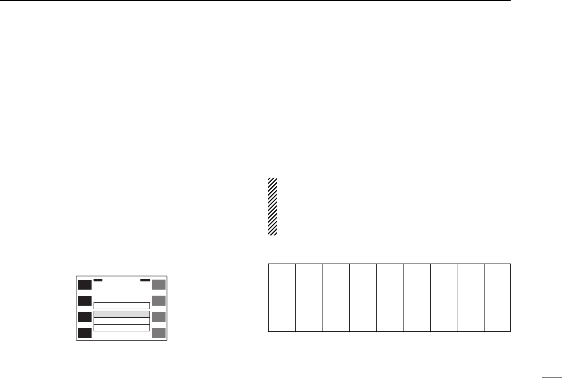
•Available subaudible tone frequencies (unit: Hz)
67.0
69.3
71.9
74.4
77.0
79.7
82.5
85.4
88.5
91.5
94.8
97.4
100.0
103.5
107.2
110.9
114.8
118.8
123.0
127.3
131.8
136.5
141.3
146.2
151.4
156.7
159.8
162.2
165.5
167.9
171.3
173.8
177.3
179.9
183.5
186.2
189.9
192.8
196.6
199.5
203.5
206.5
210.7
218.1
225.7
229.1
233.6
241.8
250.3
254.1
ï
Y
Z
CH
SKIP
MW
MEMORY EDIT
(TS=
12.5
k)
Name ICOM
2800
R-Tone
C-Tone
OW
123.0
88.5
0.6000
145.320
12

30
6REPEATER OPERATION
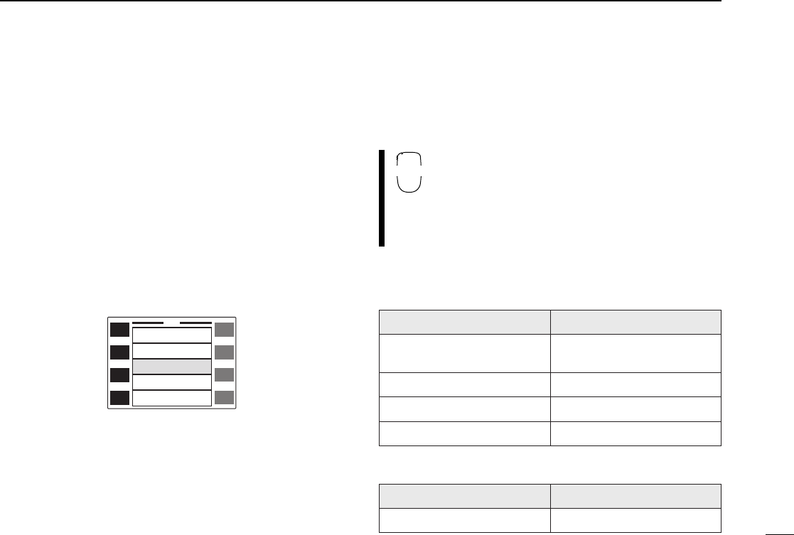
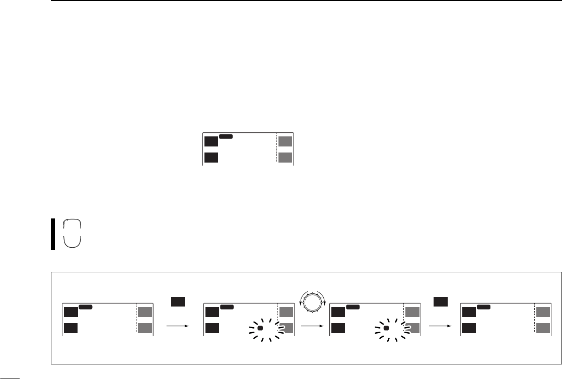
■Offset frequency
When communicating through a repeater, the transmit fre-
quency is shifted from the receive frequency by an amount
determined by the offset frequency.
qSelect the mode/channel you wish to set the offset fre-
quency to, such as VFO mode or memory/call channel.
wPush the desired band’s [(MAIN)EDIT] for 2 sec. to enter the
edit screen.
•Push [CHG/L] if [(MAIN)EDIT] is not displayed.
ePush [Y] or [Z] to select the ‘OW’ item.
•Left-hand tuning dial can also select the item.
rRotate the right-hand tuning dial to select the desired fre-
quency.
•The offset frequency is set temporarily. Push [MW] for 2 sec. to
store the offset frequency permanently.
•Push [MHz] to toggle the 1 MHz tuning step ON and OFF.
•The color of the frequency indication changes when the setting is
different from the memory or call channel contents.
tIf you want to set other channels, push [CH] then rotate the
right-hand tuning dial. Repeat eand rto select the de-
sired frequency.
yPush [ï] to exit the edit screen.
ï
Y
Z
CH
SKIP
MW
MEMORY EDIT
(TS=
12.5
k)
Name ICOM
2800
R-Tone
C-Tone
OW
123.0
88.5
0.600
145.320
12
MHz
31
6
REPEATER OPERATION
■Auto repeater function
(U.S.A. and Korea versions only)
The U.S.A. and Korea versions automatically activate the re-
peater settings (duplex ON/OFF, duplex direction, tone en-
coder ON/OFF) when the operating frequency falls within or
outside of the general repeater output frequency range. The
offset and repeater tone frequencies are not changed by the
auto repeater function, reset these frequencies, if necessary.
qPush [(DISP)SET] for 2 sec. to enter set mode.
•Push [CHG/L] if [(DISP)SET] is not displayed.
wPush [Y] or [Z] to select the ‘Auto Repeater’ item.
•Left-hand tuning dial can also select the item.
eRotate the right-hand tuning dial to select the auto repeater
function.
U.S.A. version:
•“Dup” Activates duplex only.
•“Dup&Tone” Activates duplex and tone.
•“OFF” Auto repeater function is turned OFF.
Korea version:
•“ON” Activates duplex and tone.
•“OFF” Auto repeater function is turned OFF.
rPush [ï] to exit set mode.
qPush [FSET] to enter set mode.
wPush [FSET] or [GENT] to select the ‘Auto Re-
peater’ item.
ePush [Y] or [Z] to select the auto repeater
function.
rPush [ECLR] to exit set mode.
DFrequency range and offset direction
•U.S.A. version
•Korea version
FREQUENCY RANGE DUPLEX DIRECTION
145.200–145.495 MHz
146.610–146.995 MHz “DUP–” appears
147.000–147.395 MHz “DUP” appears
442.000–444.995 MHz “DUP” appears
447.000–449.995 MHz “DUP–” appears
FREQUENCY RANGE DUPLEX DIRECTION
439.000–440.000 MHz “DUP–” appears
ï
Y
Z
SET
Operation Beep ON
OFF
OFF
OFF
Auto
Tx T.O.T.
Auto Repeater
Auto Power-Off
Cooling Fan
SET
B
■General
The transceiver has 99 memory channels and 1 call channel
for each band for storage of often-used frequencies.
DMemory/call channel contents
The following information can be programmed into memory
or call channels:
•Operating frequency (p. 20)
•Operating mode (p. 74)
•8-character memory name (p. 37)
•Tuning step (p. 21)
•Duplex direction (DUP or DUP–) with an offset frequency
(pgs. 26, 30)
•Subaudible tone encoder or tone squelch ON/OFF (pgs. 26,
50)
•Subaudible tone and tone squelch frequencies (pgs. 29, 51)
•Scan skip setting (p. 46)
■
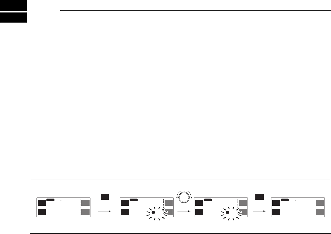
Programming during selection
qSelect VFO mode with the desired band’s [V/M
H
].
•Push [CHG/L] if [V/M
H
] is not displayed.
wSet the desired frequency:
➥Set the frequency using the desired band’s tuning dial.
➥Set other data (e.g. offset frequency, duplex direction,
subaudible tone frequency, etc.), if required.
ePush the desired band’s [S.MW] momentarily to indicate
memory channels.
•Push [CHG/L] if [S.MW] is not displayed.
•Do not hold [S.MW] for more than 0.5 sec., otherwise the mem-
ory channel will overwrite the selected memory channel.
rRotate the tuning dial to select the desired channel.
•Call channel (C), VFO (- -) and scan edges (1A – 3B), as well as
regular memory channels, can be programmed in this way.
tPush [(S.MW)MW] for 2 sec. to program.
•Memory channel number automatically advances when continu-
ing to push [(S.MW)MW] after programming.
32
7MEMORY/CALL CHANNELS
MAIN
1
14
5.680
MID-LO
DUP SQL
T
MAIN
EDIT EDIT
MAIN
TON
DUP TON
DUP
MAIN
40
14
5.680
MID-LO
DUP SQL
T
MAIN
EDIT EDIT
MAIN
TON
DUP TON
DUP
MAIN
1
14
6.010
MID-LO
M
MAIN
EDIT EDIT
MAIN
TON
DUP TON
DUP
MAIN
40
5.
MID-LO
M
MAIN
EDIT EDIT
MAIN
TON
DUP TON
DUP
S.MW
MW
S.MW
MW
momentarily
blank channel
for 2 sec.
[EXAMPLE]: Programming ch 40 during selection.
33
7
MEMORY/CALL CHANNELS
■Programming after selection
qSelect memory mode with the desired band’s [M/C].
•Push [CHG/L] if [M/C] is not displayed.
•“!” appears when memory mode is selected.
wSet the memory channel to be programmed with the de-
sired band’s tuning dial.
ePush [V/M
H
] to select VFO mode.
rSet the desired frequency:
➥Set the frequency using the desired band’s tuning dial.
➥Set other data (e.g. offset frequency, duplex direction,
subaudible tone frequency, etc.), if required.
tPush [(S.MW)MW] for 2 sec. to program into the selected
channel.
•Push [CHG/L] if [(S.MW)MW] is not displayed.
•Memory channel number automatically advances when continu-
ing to push [MW] after programming.
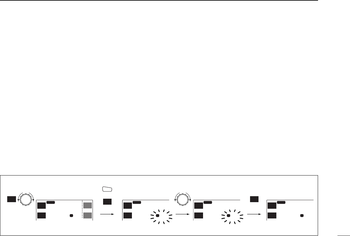
■Transferring memory
contents to another memory
qSelect memory mode with the desired band’s [M/C].
•Push [CHG/L] if [M/C] is not displayed.
•“!” appears when memory mode is selected.
wSet the desired memory channel with the desired band’s
tuning dial.
ePush the desired band’s [S.MW] momentarily to indicate
memory channels.
•Push [CHG/L] if [S.MW] is not displayed.
•Push [S.MW] for 2 sec. to transfer the memory channel contents
to VFO.
rRotate the tuning dial to select the desired channel.
•Call channel (C), VFO (- -) and scan edges (1A – 3B), as well as
regular memory channels, can be transferred in this way.
tPush [(S.MW)MW] for 2 sec. to transfer.
MAIN
3
14
6.340
MID-LO
MAIN
20
14
6.340
MID-LO
MAIN
EDIT
TON
DUP
MAIN
- -
14
6.010
MID-LO
M
MAIN
EDIT
TON
DUP
MAIN
20
5.
MID-LO
M M
MAIN
EDIT
TON
DUP
S.MW
MW
S.MW
MW
SCP
MAIN
TS
V/M
H
SCN
M/C
SCP
MAIN
TS
V/M
H
M
Select memory
channel
momentarily
blank channel
for 2 sec.
CHG/L
[EXAMPLE]: Transferring VHF memory channel 3 to 20.

34
7MEMORY/CALL CHANNELS
■Programming during
selection via the microphone
The HM-98 microphone can also be used to pro-
gram memory channels.
qSelect the desired band with [BAND].
wSelect VFO mode with [VFO].
eSet the desired frequency.
•Set other data (e.g. offset frequency, duplex direction, subaudible
tone frequency, etc.), if required.
rPush [FUNC] then [EMW] momentarily to indicate mem-
ory channels.
•Do not hold [MW] for more than 0.5 sec., otherwise the memory
channel will overwrite the selected memory channel.
tPush [Y] or [Z] to select the desired channel.
•Call channel (C), VFO (- -) and scan edges (1A – 3B), as well as
regular memory channels, can be programmed in this way.
yPush [FUNC] then [EMW] for 2 sec. to program.
•Memory channel number automatically advances when continu-
ing to push [MW] after programming.
■Programming after selection
via the microphone
The HM-98 microphone can also be used to pro-
gram memory channels.
qSelect the desired band with [BAND].
wSelect memory mode with [MR].
eSet the desired memory channel to be programmed with
[Y] or [Z].
rPush [VFO] to select VFO mode.
tSet the desired frequency:
•Set other data (e.g. offset frequency, duplex direction, subaudible
tone frequency, etc.), if required.
yPush [FUNC] then [EMW] for 2 sec. to program.
•Memory channel number automatically advances when continu-
ing to push [MW] after programming.
MW
A
MW
A

35
7
MEMORY/CALL CHANNELS
■Transferring memory
contents to another memory
via the microphone
The HM-98 microphone can also be used to trans-
fer memory channels.
qSelect the desired band with [BAND].
wSelect memory mode with [MR].
eSet the desired memory channel to be transferred with [Y]
or [Z].
rPush [FUNC] then [EMW] momentarily to indicate mem-
ory channels.
•Push [MW] for 2 sec. to transfer the memory channel contents to
VFO.
tPush [Y] or [Z] to select the desired channel.
•Call channel (C), VFO (- -) and scan edges (1A – 3B), as well as
regular memory channels, can be transferred in this way.
yPush [FUNC] then [EMW] for 2 sec. to transfer.
MW
A
36
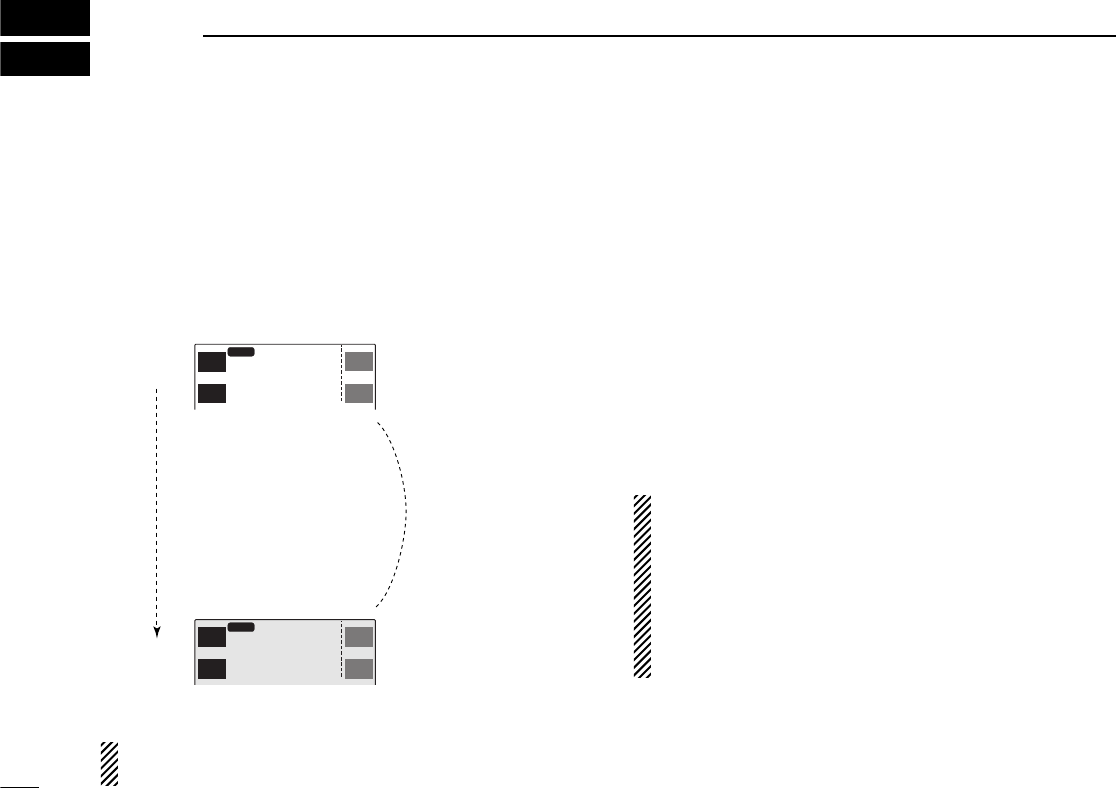
7MEMORY/CALL CHANNELS
■Memory clear
Unwanted memory channels can be cleared (erased). Before
clearing a memory channel make sure it is no longer needed
as cleared memories cannot be recalled.
qPush the desired band’s [S.MW] momentarily.
•Push [CHG/L] if [S.MW] is not displayed.
•Do not hold [S.MW] for more than 0.5 sec., otherwise the mem-
ory channel will overwrite the selected memory channel or the
memory channel contents will be transferred to VFO.
wSet the memory channel to be cleared with the desired
band’s tuning dial.
ePush [S.MW] briefly, then a second time for 2 sec.
•3 beeps sound, then the frequency is cleared.
•Scan edges 1A/1B and the call channel cannot be cleared.
rPush [MAIN] to return to previous mode.
Be careful—the contents of cleared memories CANNOT
be recalled.
Memory clearing may not be performed from the
microphone.
MAIN
3
14
6.340
MID-LO
MAIN
- -
14
6.010
MID-LO
M
MAIN
EDIT
TON
DUP
MAIN
3
MID-LO
M
MAIN
EDIT
TON
DUP
SCP
MAIN
TS
V/M
H
SCN
M/C
MW
S.MW MAIN
3
5.
MID-LO
M
MAIN
EDIT
TON
DUP
M
MW
S.MW
MW
S.MW
EDIT
MAIN
14
6.340
Select memory
channel
momentarily for 2 sec.
briefly
CHG/L
[EXAMPLE]: Clearing memory channel 3.
37
7
MEMORY/CALL CHANNELS
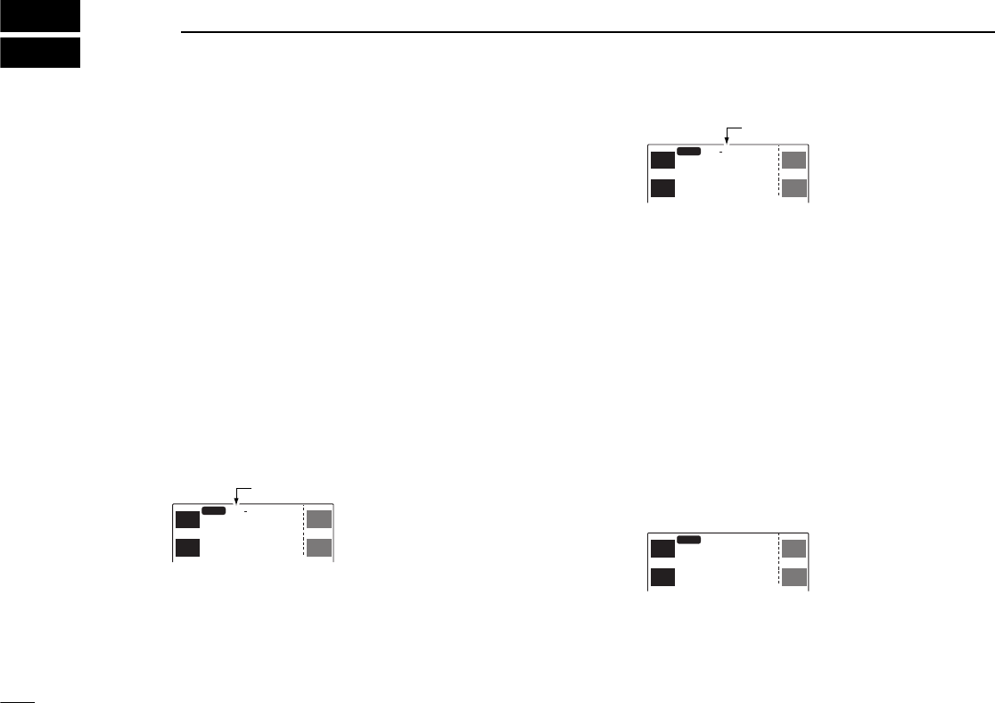
■Alphanumeric display
Each memory channel and the call channel can be pro-
grammed with an alphanumeric name such as a repeater
name, club name, etc., for easy recognition. Names can be a
maximum of 8 characters—see the table at right for available
characters.
Scan edge channels and scratch pad memories CANNOT
be programmed with alphanumeric names.
qSelect the desired memory/call channel except scan edge
channels.
wPush the desired band’s [(MAIN)EDIT] for 2 sec. to enter the
edit screen.
•Push [CHG/L] if [(MAIN)EDIT] is not displayed.
ePush [Y] or [Z] to select the ‘Name’ item.
•Left-hand tuning dial can also select the item.
rPush [EDIT] to enter programming mode.
•The first character of the name flashes.
tRotate the right-hand tuning dial to select the desired char-
acter.
•See the table below for a list of available characters.
yPush [≈] to advance to the next character.
•Push [Ω] to select the previous character.
uRepeat tand yuntil the desired name is input.
iPush [ï] to program the name and exit programming
mode.
oIf you want to set other channels, push [CH] then rotate the
right-hand tuning dial. Repeat rthrough ito set the de-
sired name.
!0 Push [ï] again to exit the edit screen.
To display the programmed memory name, turn the mem-
ory name indication ON in set mode. (p. 67)
<>+–=M/_()
: 012345678
9ABCDEFGHI
JKLMNOPQRS
TUVWXYZ
space
ï
Y
Z
CH
SKIP
MW
MEMORY EDIT
(TS=
12.5
k)
Name ICOM
2800
R-Tone
C-Tone
OW
123.0
88.5
0.6000
145.320
12
EDIT
MID-LO
ICOM2800
14
5.320
12
EDIT
MAIN
DUP
TON
EDIT
MAIN
DUP
TON
MAIN
38
7MEMORY/CALL CHANNELS
■Call channel
1 call channel is available for each band to store a most-often-
used frequency for quick recall.
DSelecting a call channel
qPush [M/C] to select a call chan-
nel.
•Push [CHG/L] if [M/C] is not dis-
played.
•“C” appears when call channel is
selected.
wPush [V/M
H
] to select VFO mode, if desired.
qSelect the desired band with [BAND].
wPush [(MR)CALL] for 2 sec. to select the se-
lected band’s call channel.
DProgramming a call channel
qSelect VFO mode with the desired band’s [V/M
H
].
•Push [CHG/L] if [V/M
H
] is not displayed.
wSet the desired frequency:
➥Set the frequency using the desired band’s tuning dial.
➥Set other data (e.g. offset frequency, duplex direction,
subaudible tone frequency, etc.), if required.
ePush the desired band’s [S.MW] momentarily to indicate
memory channels.
•Push [CHG/L] if [S.MW] is not displayed.
•Do not hold [S.MW] for more than 0.5 sec., otherwise the mem-
ory channel will overwrite the selected memory channel.
rRotate the tuning dial to select the call channel.
•“C” appears when a call channel is selected.
tPush [(S.MW)MW] for 2 sec. to program.
MID-LO
C
MAIN
SCP
MAIN
TS
V/M
H
SCP
MAIN
TS
V/M
H
14
6.010
MAIN
1
14
6.200
MID-LO
MAIN
EDIT EDIT
MAIN
TON
DUP TON
DUP
MAIN
1
14
6.200
MID-LO
MAIN
EDIT EDIT
MAIN
TON
DUP TON
DUP
MAIN
1
14
6.010
14
6.010
MID-LO
M
MAIN
EDIT EDIT
MAIN
TON
DUP TON
DUP
MAIN
MID-LO
M
MAIN
EDIT EDIT
MAIN
TON
DUP TON
DUP
S.MW
MW
S.MW
MW
C
momentarily
call channel
for 2 sec.
[EXAMPLE]: Programming a call channel.
CALL

39
7
MEMORY/CALL CHANNELS
DProgramming a call channel via the
microphone
The HM-98 microphone can also be used to pro-
gram a call channel.
qSelect the desired band with [BAND].
wSelect VFO mode with [VFO].
eSet the desired frequency.
•Set other data (e.g. offset frequency, duplex direction, subaudible
tone frequency, etc.), if required.
rPush [FUNC] then [EMW] momentarily to indicate mem-
ory channels.
•Do not hold [MW] for more than 0.5 sec., otherwise the memory
channel will overwrite the selected memory channel.
tPush [Y] or [Z] to select the call channel.
•“C” appears when the call channel is selected.
yPush [FUNC] then [EMW] for 2 sec. to program.
DTransferring call channel contents
The call channels can be transferred in a similar manner to
memory channel transferring.
qSelect call channel with the desired band’s [M/C].
•Push [CHG/L] if [M/C] is not displayed.
•“C” appears when the call channel is selected.
wPush [(S.MW)MW] for 2 sec. to transfer.
•Push [CHG/L] if [S.MW] is not displayed.
DTransferring call channel contents via the
microphone
qSelect the desired band with [BAND].
wPush [(MR)CALL] for 2 sec. to select the desired band’s call
channel.
•“C” appears when the call channel is selected.
ePush [FUNC] then [EMW] for 2 sec. to transfer.
MW
A
40
8SCRATCH PAD MEMORY
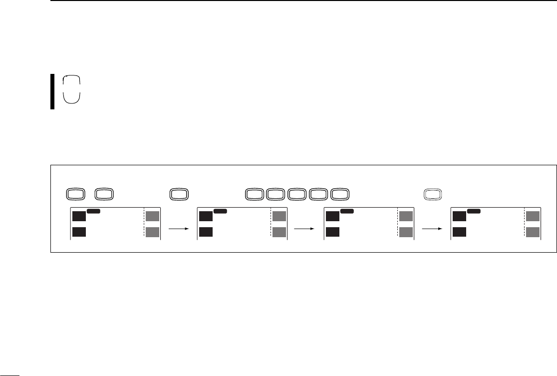
■
What is a scratch pad memory?
During VFO operation, the transceiver automatically memo-
rizes operating frequency information, separate from regular
memory channels, when transmitting on a new frequency.
There are 2 types of scratch pad memories, those for simplex
operation, L1–L5, and those for duplex (repeater) operation,
R1–R5. These memories can be conveniently recalled.
When memory mode is selected, the frequency is not pro-
grammed into a scratch pad.
■Calling up a scratch pad
memory
qPush [M/C] to select the call channel.
•Push [CHG/L] if [M/C] is not displayed.
•“C” appears when the call channel is selected.
wRotate the desired band’s tuning dial to select a scratch
pad memory.
•Previously transmitted frequency and one of “L1–L5” appears for
simplex memories (rotate tuning dial left); one of “R1–R5” ap-
pears for duplex memories (rotate tuning dial right).
•When first applying power or after CPU resetting, scratch pad
memories contain no data and therefore cannot be selected.
ePush [V/M
H
] or [M/C] to exit the scratch pad memory.
•The 5th scratch pad memory (L5 or R5) will be cleared
when transmitting on a new frequency. If the transmit fre-
quency is already stored in a scratch pad memory, the
scratch pad memory is not cleared but the order is
changed.
•When transmitting on a scratch pad memory, that memory
becomes the 1st scratch pad memory (L1 or R1) and the
order is changed.
MAIN
L1
14
5.850
L2
14
5.650
L3
14
5.550
L4
14
5.400
L5
14
5.360
L5
14
5.700
MID-LO
SCP
MAIN
TS
V/M
H
SCP
MAIN
TS
V/M
H
MAIN
SCP
MAIN
TS
V/M
H
SCP
MAIN
TS
V/M
H
Newest
Oldest
The oldest written frequency is cleared.
Order is changed if
transmitting on
these channels.

41
8
SCRATCH PAD MEMORY
qSelect the desired band with [BAND].
wPush [(MR)CALL] for 2 sec. to select the se-
lected band’s call channel.
ePush [Y] one or more times to select a duplex
scratch pad memory; push [Z] one or more
times to select a simplex scratch pad memory.
rPush [MR] or [VFO] to exit the scratch pad
memory.
■Transferring scratch pad
memory contents
Transferring scratch pad memory contents to the VFO is done
similarly to transferring memory/call contents.
qPush [M/C] to select the call channel.
•Push [CHG/L] if [M/C] is not displayed.
•“C” appears when the call channel is selected.
wRotate the desired band’s tuning dial to select the desired
scratch pad memory.
•One of “L1” to “L5” or “R1” to “R5” appears.
ePush the desired band’s [S.MW] momentarily to indicate
memory channels.
•Push [S.MW] for 2 sec. to transfer the scratch pad memory to
VFO.
rRotate the desired band’s tuning dial to select the desired
memory channel.
tPush [(S.MW)MW] for 2 sec. to transfer.
qSelect the desired band with [BAND].
wPush [(MR)CALL] for 2 sec. to select the se-
lected band’s call channel.
ePush [Y] one or more times to select a duplex
scratch pad memory; push [Z] one or more
times to select a simplex scratch pad memory
to be transferred.
rPush [FUNC] then [EMW] momentarily to indi-
cate memory channels.
•Push [MW] for 2 sec. to transfer the scratch pad
memory to VFO.
tPush [Y] or [Z] to select the desired channel.
•Call channel (C), VFO (- -) and scan edges (1A –
3B), as well as regular memory channels, can be
transferred in this way.
yPush [FUNC] then [EMW] for 2 sec. to trans-
fer.
MW
A
CALL
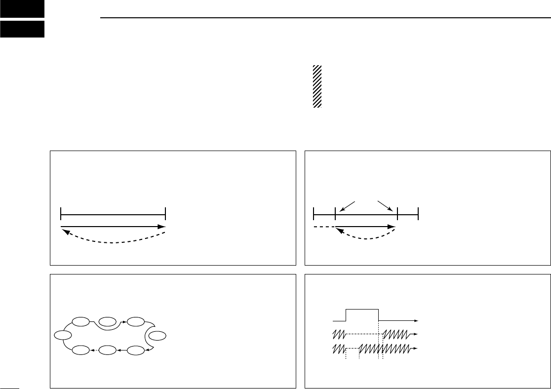
MEMORY SCAN (p. 45) Repeatedly scans memory
channels except those set as
skip channels. Used to search
through often-used memories
and for bypassing normally
busy channels such as re-
peater frequencies.
FULL/BAND SCAN (p. 43) Repeatedly scans all frequen-
cies over the entire band.
Used as the simplest scan
without any preliminary set-
tings necessary.
Band
edge
Band
edge
Scan
Jump
Not yet
programmed
≈
(skip)
ch 99
ch 1 ch 2 ch 3
ch 4
ch 5
ch 6ch 98
PROGRAMMED SCAN
(p. 43)
Repeatedly scans between
two user-programmed fre-
quencies. Used for checking
for frequencies within a speci-
fied range such as repeater
output frequencies, etc. 3
pairs of scan edges are avail-
able.
Scan
Jump
Scan edges
Band
edge Band
edge
SCAN RESUME
CONDITION (p. 46)
4 resume conditions are avail-
able: 3 timer scans and pause
scan. When receiving a sig-
nal, pause scan pauses until
the signal disappears; timer
scans pause for 5, 10 or 15
sec.
Pause
scan
Receiving
a signal
Timer
scan
Pausing 2 sec.
42
9SCAN OPERATION
■Scan types
Scanning searches for signals automatically and makes it
easier to locate new stations for contact or listening purposes.
There are 3 scan types and 4 resume conditions to suit your
operating needs.
A tone scan function is available to search for subaudible
tones (e.g. when you want to find a subaudible tone fre-
quency necessary to open a repeater). See p. 53 for de-
tails.
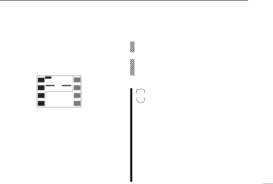
43
9
SCAN OPERATION
■Full/programmed scan
qSelect VFO mode with the desired band’s [V/M
H
].
•Push [CHG/L] if [V/M
H
] is not displayed.
wMake sure the squelch is set to the threshold point.
ePush [(M/C)SCN] for 2 sec. to enter scan screen.
•If the pocket beep function is activated, the transceiver automat-
ically selects the tone squelch function when the scan screen is
selected.
rPush [SEL] one or more times to select the desired scan
edges, if necessary. See p. 44 for details.
•“AL” for full scan, “AA” for air band scan (U.S.A. and S. America
versions only), “A1”/“A4” for 144 MHz/430(440) MHz band scan
or “P1”–“P3” for programmed scan.
•Only programmed scan edges can be selected.
tPush [PRO] momentarily to start the scan.
•Decimal point flashes while scanning.
•“AL,” “AA”/“A1”/“A4” or “P1”– “P3” flashes to indicate full scan,
band scan or programmed scan edges, respectively.
•To change the scanning direction, rotate the desired band’s tun-
ing dial.
•To change the scan edges, push [SEL] one or more times.
yTo stop the scan, push [PRO] again.
uPush [(MAIN)í] for 2 sec. to exit the scan screen.
If the same frequencies are programmed into a pair of
scan edges, programmed scan does not start.
For programmed scan, scan edges must be programmed
in advance. Program scan edges into scan edge memory
channels (1A–3B). (p. 32)
qSelect the desired band with [BAND].
wSelect VFO mode with [VFO].
ePush [SQLY] or [SQLZ] to set the squelch to
the threshold point.
rSelect the desired scan edges using the con-
troller unit, if necessary. See p. 44 for details.
•“AL” for full scan, “AA” for air band scan (U.S.A. and
S. America versions only), “A1”/“A4” for 144 MHz/
430(440) MHz band scan or “P1”–“P3” for pro-
grammed scan.
•Only programmed scan edges can be selected.
tPush [wSCAN] momentarily to start a scan.
Push [Y]/[Z] for 2 sec. to start a band scan.
•“AL,” “AA”/“A1”/“A4” or “P1”–“P3” flashes to indicate
full scan, band scan or programmed scan edges, re-
spectively.
yPush [Y], [Z] or [ECLR] to cancel the scan.
M-L
SCAN
P1
144.2-145.8
Resume Pause
145.320
12
MAIN
43
3.000
12
í
MAIN
PRIO
PRO
TON
Res
SEL
SCP
MAIN
TS
V/M
H
SCN
M/C
LOW
MONI
MID-LO
Y Z
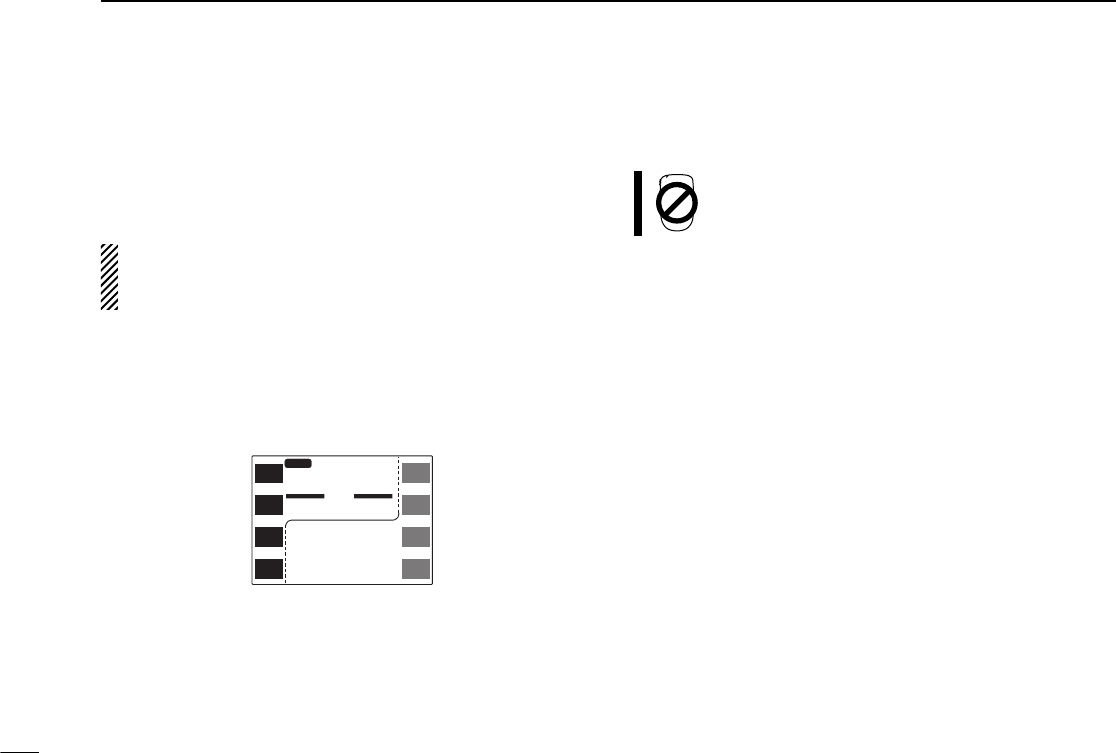
■Selecting scan edges
The scanning range can be set to all frequencies (full scan) or
between two user-programmed frequencies (programmed
scan).
Scan edges can be programmed in the same manner as
memory channels. Scan edges are programmed into scan
edges, 1A/1B to 3A/3B, in memory channels. (p. 32)
qPush [(M/C)SCN] for 2 sec. to enter the scan screen.
•Push [CHG/L] if [(M/C)SCN] is not displayed.
•If the pocket beep function is activated, the transceiver automat-
ically selects the tone squelch function when the scan screen is
selected.
wPush [SEL] one or more times to select the desired scan
edges, if necessary.
•“AL” for full scan, “AA” for air band scan (U.S.A. and S. America
versions only), “A1”/“A4” for 144 MHz/430(440) MHz band scan
or “P1”–“P3” for programmed scan.
•Only programmed scan edges can be selected.
ePush [(MAIN)í] for 2 sec. to exit the scan screen.
Scan edge selection may not be performed from
the microphone.
44
9SCAN OPERATION
M-L
SCAN
P1
144.2-145.8
Resume Pause
145.320
12
MAIN
43
3.000
12
í
MAIN
PRIO
PRO
TON
Res
SEL
SCP
MAIN
TS
V/M
H
SCN
M/C
LOW
MONI
MID-LO

45
9
SCAN OPERATION
■Memory scan
qSelect memory mode with the desired band’s [M/C].
•Push [CHG/L] if [M/C] is not displayed.
•“!” appears when memory mode is selected.
wMake sure the squelch is set to the threshold point.
ePush [(M/C)SCN] for 2 sec. to enter the scan screen.
•If the pocket beep function is activated, the transceiver automat-
ically selects the tone squelch function when the scan screen is
selected.
rPush [MEM] momentarily to start the scan.
•Decimal point and“!” flash while scanning.
•To change the scanning direction, rotate the desired band’s tun-
ing dial.
tTo stop the scan, push [MEM] again.
yPush [(MAIN)í] for 2 sec. to exit the scan screen.
qSelect the desired band with [BAND].
wSelect memory mode with [MR].
ePush [SQLY] or [SQLZ] to set the squelch to
the threshold point.
rPush [wSCAN] momentarily or [Y]/[Z] for 2
sec. to start memory scan.
•Decimal point and“!” flash while scanning.
tPush [Y], [Z] or [ECLR] to cancel the scan.
At least 2 memory channels must be programmed for
memory scan to start.
Y Z
M-L
SCAN
144.0-146.0
Resume 15s
145.320
12
MAIN
43
3.000
12
í
MAIN
PRIO
MEM
TON
Res
SEL
SCP
MAIN
TS
V/M
H
SCN
M/C
LOW
MONI
MID-LO
M
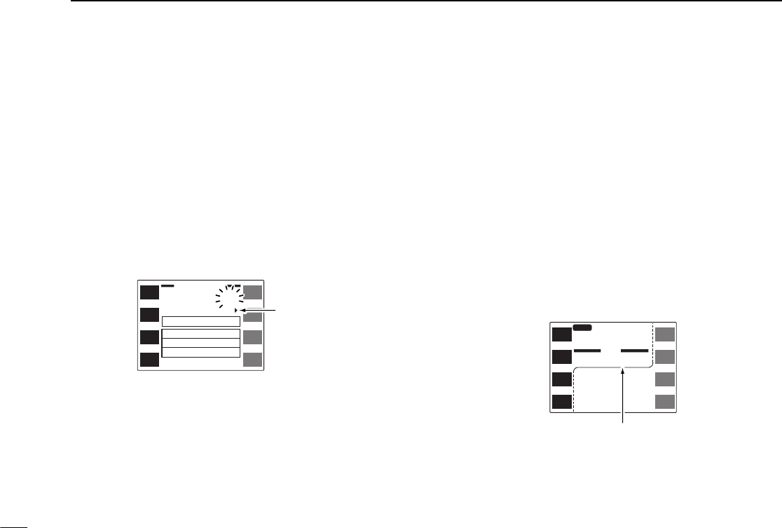
46
9SCAN OPERATION
■Skip channel setting
Memory channels can be set to be skipped for memory skip
scan. In addition, memory channels can be set to be skipped
for both memory skip scan and full/band/programmed scan
(frequency skip scan). This is useful to speedup the scan in-
terval.
qSelect a memory channel you wish to set skip information.
wPush the desired band’s [(MAIN)EDIT] for 2 sec. to enter the
edit screen.
•Push [CHG/L] if [(MAIN)EDIT] is not displayed.
ePush [SKIP] to select the condition.
•“≈” for memory skip scan.
•“P≈” for frequency skip scan and memory skip scan.
•No “≈” or “P≈” indication for no skipping of channels.
rIf you want to set other channels, rotate the right-hand tun-
ing dial. Repeat eto set the desired condition.
•Push [CH] if memory channel does not flash.
tPush [ï] to exit the edit screen.
■Scan resume condition
The scan resume condition can be selected as a pause or
timer scan for each band. When receiving signals, the scan
pauses according to the scan resume condition.
qPush the desired band’s [(M/C)SCN] for 2 sec. to enter scan
screen.
•Push [CHG/L] if [(M/C)SCN] is not displayed.
wPush [(SEL)Res] one or more times for 2 sec. to select con-
dition.
•“5s” : scan pauses for 5 sec. on a received signal.
•“10s” : scan pauses for 10 sec. on a received signal.
•“15s” : scan pauses for 15 sec. on a received signal.
•“Pause” : scan pauses on a received signal until it disappears.
ePush [(MAIN)í] for 2 sec. to exit scan screen.
ï
Y
Z
CH
SKIP
MW
MEMORY EDIT
(TS=
12.5
k)
Name ICOM
2800
R-Tone
C-Tone
OW
123.0
88.5
0.6000
145.320
12
P
Skip channel
information
M-L
SCAN
P1
144.2-145.8
Resume 15s
145.320
12
MAIN
43
3.000
12
í
MAIN
PRIO
PRO
TON
Res
SEL
SCP
MAIN
TS
V/M
H
SCN
M/C
LOW
MONI
MID-LO
15 sec. resume time
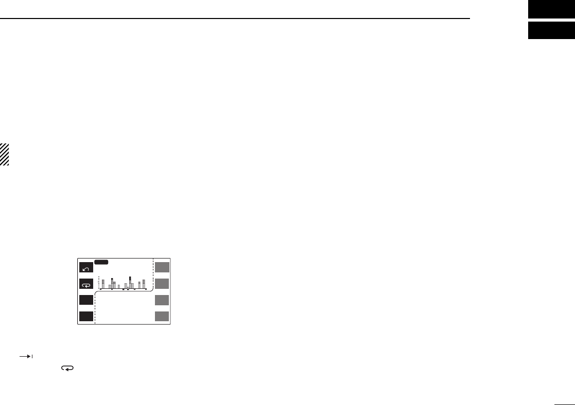
47
10
BAND SCOPE
■Operation
The band scope function allows you to visually check a spec-
ified frequency range. Sweep range varies ±50 kHz through
±500 kHz with setting of the sweep tuning steps.
Receive audio is muted while monitoring the band scope.
Push [SWP] to cancel sweeping and receive the audio.
qSet the desired frequency as band scope center frequency.
wPush the desired band’s [(MAIN)SCP] for 2 sec. to select the
band scope screen.
•Push [CHG/L] if [(MAIN)SCP] is not displayed.
eA sweep automatically starts and signal conditions
(strengths) appear starting from the center of the range.
rPush [SWP] momentarily to begin another sweep.
•“ ” appears while sweeping.
tPush [(SWP) ] for 2 sec. to begin sweeping continuously.
•Push [SWP] again to cancel sweeping.
yPush [TS] to select the sweep tuning step, if desired.
•5, 10, 15, 20, 25, 30 and 50 kHz sweep tuning steps are available
when a tuning step other than 12.5 kHz is selected.
•12.5, 25 and 50 kHz sweep tuning steps are available when 12.5
kHz tuning step is selected.
uRotate the desired band’s tuning dial to set the highlighted
cursor to the desired waveform and set the frequency of
the signal.
•Push [CENT] to return the operating frequency to the center fre-
quency.
iPush [(MAIN)í] for 2 sec. to exit the band scope screen.
MAIN
MAIN SCP
M-L
SWP
CENT
145.060
12
43
3.000
12
SCP
MAIN
TS
V/M
H
SCN
M/C
LOW
MONI
MID-LO
10k
TS
MAIN
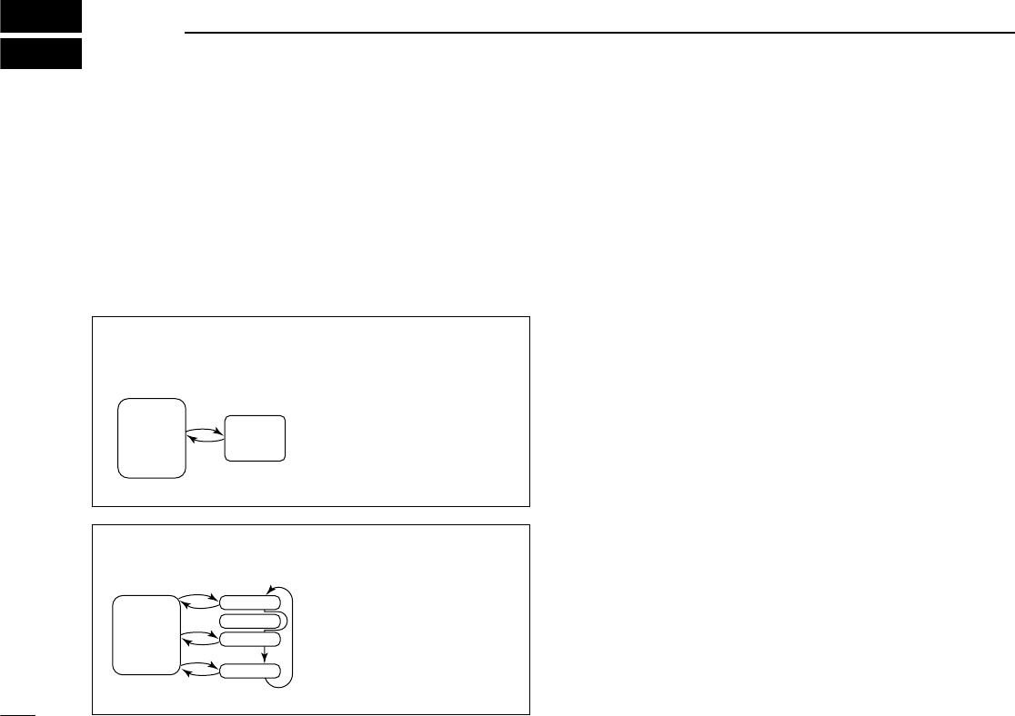
■Priority watch types
Priority watch checks for signals on a frequency every 5 sec.
while operating on a VFO frequency. The transceiver has 2
priority watch types to suit your needs.
The watch resumes according to the selected scan resume
condition. See p. 46 for details.
■Priority watch operation
qSelect VFO mode with the desired band’s [V/M
H
].
•Push [CHG/L] if [V/M
H
] is not displayed.
wSet an operating frequency.
eMake sure the squelch is set to the threshold point.
rSet the watching channel(s).
For memory channel watch:
Select the desired memory channel.
•Select memory mode with the desired band’s [M/C] (“!”ap-
pears.); select the memory channel to be watched with the de-
sired band’s tuning dial.
For memory scan watch:
Start the memory scan.
•Select memory mode with the desired band’s [M/C] (“!”ap-
pears.); push [(M/C)SCN] for 2 sec. to select scan screen; push
[MEM] to start memory scan.
For call channel watch:
Select the call channel by pushing [M/C].
•Select memory mode with the desired band’s [M/C]. (“C” ap-
pears.)
tPush [(M/C)SCN] for 2 sec. to select the scan screen.
•If the pocket beep function is activated, the transceiver automat-
ically selects the tone squelch function when scan screen is se-
lected.
48
11 PRIORITY WATCH
MEMORY or CALL
CHANNEL WATCH
While operating on a VFO
frequency, priority watch
checks for a signal on the
selected memory or call
channel every 5 sec.
•A memory channel with skip in-
formation can be watched.
MEMORY SCAN WATCH While operating on a VFO
frequency, priority watch
checks for signals on each
memory channel in se-
quence.
•The memory skip function is
useful to speed up the scan.
VFO
frequency
Memory
or call
channel
5 sec. 125 msec.
VFO
frequency
Mch 1
Mch 0
Mch 2
Mch 99
5 sec. 125 msec.
≈Skip

49
11
PRIORITY WATCH
yPush [(MEM)PRIO] for 2 sec. to start the watch.
•The transceiver checks the memory or call channel frequency
every 5 sec.
•The watch resumes according to the selected scan resume con-
dition. (p. 46)
•“PRIO” and decimal point blinks while receiving a signal on a
watch channel.
uPush [(MEM) PRIO] while the display shows the VFO fre-
quency to stop the watch.
qSelect the desired band with [BAND].
wSelect VFO mode with [VFO].
eSet an operating frequency.
rPush [SQLY] or [SQLZ] to set the squelch to
the threshold point.
tSet the watching channel(s).
For memory channel watch:
Select the desired memory channel.
•Select memory mode with [MR]; select the memory
channel to be watched with [Y]/[Z].
For memory scan watch:
Start the memory scan.
•Select memory mode with [MR]; push [wSCAN]
momentarily or [Y]/[Z] for 2 sec. to start memory
scan.
For call channel watch:
Select the call channel by pushing [(MR)CALL]
for 2 sec.
yPush [ePRIO] to start the watch.
•The transceiver checks the memory or call channel
frequency every 5 sec.
•The watch resumes according to the selected scan
resume condition. (p. 46)
•“PRIO” and decimal point blinks while receiving a
signal on a watch channel.
uPush [ePRIO] or [ECLR] while the display
shows the VFO frequency to stop the watch.
PRIO
M-L
SCAN
Resume 15s
145.320
12
MAIN
43
3.000
12
í
MAIN
PRIO
MEM
TON
Res
SEL
SCP
MAIN
TS
V/M
H
SCN
M/C
LOW
MONI
MID-LO
M
RX
PRIO
3

50
12 SUBAUDIBLE TONE OPERATION
■Tone squelch operation
The tone squelch opens only when receiving a signal con-
taining a matching subaudible tone. You can silently wait for
calls from group members using the same tone.
qSelect the desired band with the desired band’s [MAIN].
wSet an operating frequency.
eSet the desired CTCSS tone using the edit screen.
•See right for programming.
rPush [TON] one or more times until “TSQL” appears in the
function display.
•Push [CHG/L] if [TON] is not displayed.
tWhen the received signal includes a matching tone,
squelch opens and the signal can be heard.
•When the received signal’s tone does not match, tone squelch
does not open, however, the S-indicator shows signal strength.
•To open the squelch manually, push [MONI].
yOperate the transceiver in the normal way.
uTo cancel the tone squelch, push [TON] one or more times
to clear “TSQL.”
➲
CONVENIENT
Store subaudible tone frequencies and tone squelch ON/OFF
settings in memories (call) for easy recall.
qSelect the desired band with [BAND].
wSet an operating frequency.
eSet the desired CTCSS tone in the edit screen
using the remote controller unit.
•See right for programming.
rPush [FUNC] then [oTSQL] to activate the
tone squelch.
tWhen the received signal includes a matching
tone, squelch opens and the signal can be
heard.
•When the received signal’s tone does not match,
tone squelch does not open, however, the S-indica-
tor shows signal strength.
•To open the squelch manually, push [qMONI].
yOperate the transceiver in the normal way.
uTo cancel the tone squelch, push [FUNC] then
[GT-OFF].
TSQL
9
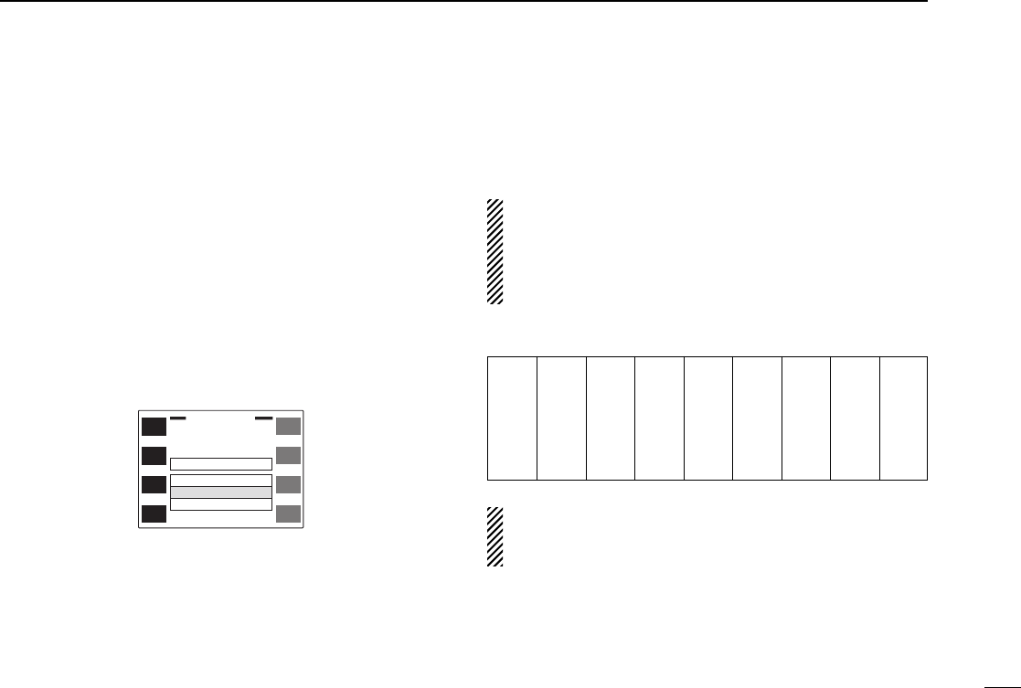
51
12
SUBAUDIBLE TONE OPERATION
DSetting subaudible tones for tone squelch
operation (CTCSS tones)
Separate tone frequencies can be set for tone squelch oper-
ation than for repeater operation (the same range of tones is
available). Like repeater tones, these are set in the edit
screen.
qSelect the mode/channel you wish to set the CTCSS tone
frequency to, such as VFO mode or memory/call channel.
wPush the desired band’s [(MAIN)EDIT] for 2 sec. to enter the
edit screen.
•Push [CHG/L] if [(MAIN)EDIT] is not displayed.
ePush [Y] or [Z] to select the ‘C-Tone’ item.
•Left-hand tuning dial can also select the item.
rRotate the right-hand tuning dial to select the desired fre-
quency.
•The CTCSS tone frequency is set temporarily. Push [MW] for 2
sec. to store the tone frequency permanently.
•The color of the frequency indication changes when the setting is
different from the memory or call channel contents.
tIf you want to set other channels, push [CH] then rotate the
right-hand tuning dial. Repeat eand rto select the de-
sired frequency.
yPush [ï] to exit the edit screen.
The tone frequency can be set in a memory channel tem-
porarily. However, the set contents are cleared once the
other memory/call channel is selected. To store the tone
frequency permanently, push [MW] for 2 sec. at step rto
overwrite the information.
•Available CTCSS tone frequencies (unit: Hz)
The transceiver has 50 tone frequencies and consequently
their spacing is narrow. Therefore, some tone frequencies
may receive interference from adjacent tone frequencies.
67.0
69.3
71.9
74.4
77.0
79.7
82.5
85.4
88.5
91.5
94.8
97.4
100.0
103.5
107.2
110.9
114.8
118.8
123.0
127.3
131.8
136.5
141.3
146.2
151.4
156.7
159.8
162.2
165.5
167.9
171.3
173.8
177.3
179.9
183.5
186.2
189.9
192.8
196.6
199.5
203.5
206.5
210.7
218.1
225.7
229.1
233.6
241.8
250.3
254.1
ï
Y
Z
CH
SKIP
MW
MEMORY EDIT
(TS=
12.5
k)
Name ICOM
2800
R-Tone
C-Tone
OW
88.5
123.0
0.6000
145.320
12

52
12 SUBAUDIBLE TONE OPERATION
■Pocket beep operation
This function uses subaudible tones for calling and can be
used as a “common pager” to inform you that someone has
called while you were away from the transceiver.
DWaiting for a call from a specific station
qSelect the desired band with the desired band’s [MAIN].
wSet an operating frequency.
eSet the desired CTCSS tone using the edit screen.
•See the previous page for programming.
rPush [TON] one or more times until “TSQLì” appears in
the function display.
•Push [CHG/L] if [TON] is not displayed.
tWhen a signal with the correct tone is received, the trans-
ceiver emits beep tones for 30 sec. and flashes “ì.”
yPush [PTT] to answer or push [TON] to stop the beeps and
flashing.
•Tone squelch is automatically selected.
uTo cancel the pocket beep, push [TON] one or more times
to clear “TSQL.”
DCalling a waiting station using pocket beep
A subaudible tone matched with the station’s tone frequency
is necessary. Use the tone squelch on p. 50 or a subaudible
tone encoder.
qSelect the desired band with [BAND].
wSet an operating frequency.
eSet the desired CTCSS tone in the edit
screen using the remote controller unit.
•See the previous page for programming.
rPush [FUNC] then [iTSQLS] to acti-
vate the pocket beep.
tWhen the received signal includes a
matching tone, the transceiver emits beep
tones for 30 sec. and flashes “ì.”
yPush [PTT] to answer or push [ECLR] to
stop the beeps and flashing.
•Tone squelch is automatically selected.
uTo cancel the pocket beep, push [FUNC]
then [GT-OFF].
TSQLS
8

53
12
SUBAUDIBLE TONE OPERATION
■Tone scan
The transceiver can detect the subaudible tone frequency in a
received signal. By monitoring a signal that is being transmit-
ted on a repeater input frequency, you can determine the tone
frequency required to access the repeater.
qSet the desired frequency or memory channel to be
checked for a tone frequency.
wTurn the tone squelch ON or OFF to check the tone
squelch frequency or repeater tone frequency, respectively.
(p. 50)
ePush the desired band’s [(M/C)SCN] for 2 sec. to enter the
scan screen.
•Push [CHG/L] if [(M/C)SCN] is not displayed.
•If the pocket beep function is activated, the transceiver automat-
ically selects the tone squelch function when the scan screen is
selected.
rPush [TON] momentarily to start the tone scan.
•Decimal point flashes while scanning.
•To change the scanning direction, rotate the desired band’s tun-
ing dial.
tWhen the tone frequency is detected, the tone scan
pauses.
•The tone frequency is set temporarily on a memory or call chan-
nel. Program into the memory or call channel to store the tone
frequency permanently.
•The decoded tone frequency is used for the repeater tone fre-
quency or tone squelch frequency, depending on the tone
squelch ON/OFF setting.
yTo stop the scan, push [TON] again.
uPush [(MAIN)í] for 2 sec. to exit the scan screen.
M-L
SCAN
Resume 15s
250.3
12
MAIN
43
3.000
12
í
MAIN
PRIO
PRO
TON
Res
SEL
SCP
MAIN
TS
V/M
H
SCN
M/C
LOW
MONI
MID-LO
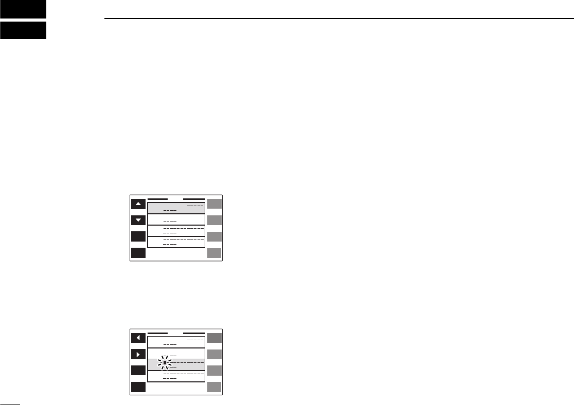
■Programming a DTMF code
DTMF codes are used for autopatching, accessing repeaters,
controlling other equipment, etc. The transceiver has 14
DTMF memory channels (D0–D9, DA–DD) for storage of
often-used DTMF codes of up to 16 digits.
qPush [DTMF] for 2 sec. to select the DTMF memory
screen.
•Push [CHG/L] if [DTMF] is not displayed.
wPush [Y] or [Z] to select the desired DTMF memory.
•Left-hand tuning dial can also select the item.
ePush [EDIT] to enter programming mode.
•The first character of the DTMF code flashes.
rRotate the right-hand tuning dial to select the desired char-
acter.
•“E” stands for “M” and “F” stands for “#.”
•“–” indicates ‘no code’ and can be used to clear a previously pro-
grammed code.
tPush [≈] to advance to the next character.
•Push [Ω] to select the previous character.
yRepeat rand tuntil the desired code is input.
uPush [ï] to program the DTMF code and exit program-
ming mode.
iIf you want to set other channels, repeat wthrough u.
oPush [ï] to exit the DTMF memory screen.
54
13 DTMF MEMORY
DTMF
D0
D1
D2
D3
0123456
0123456789
AB
Tx Time
100
ms
TIME
EDIT
DTMF
D0
D1
D2
D3
0123456
0123456789
AB
Tx Time
100
ms
ï

■Transmitting a DTMF code
DAutomatic transmission (DTMF memory)
The selected DTMF code is transmitted at each push of the
PTT switch when the DTMF memory encoder is turned ON.
qPush [DTMF] to turn the DTMF memory encoder ON.
•Push [CHG/L] if [DTMF] is not displayed.
•“ ” appears.
wPush [DTMF] for 2 sec. to select the DTMF memory
screen.
ePush [Y] or [Z] to select the desired DTMF memory.
•Left-hand tuning dial can also select the item.
rPush [ï] to exit the DTMF memory screen.
tPush [PTT] to transmit the selected DTMF code.
•Each push of [PTT] transmits the DTMF code.
•The speaker emits the DTMF tones sent.
yPush [DTMF] to cancel the DTMF memory encoder.
•“ ” disappears.
qPush [FUNC] then [yDTMF] to turn the DTMF
memory encoder ON.
•“ ” appears.
wSet the desired DTMF memory in the DTMF
memory screen using the remote controller
unit.
•Follow steps wthrough rabove.
•See the previous page for programming.
ePush [PTT] to transmit the selected DTMF code.
•Each push of [PTT] transmits the DTMF code.
rPush [ECLR] to cancel the function.
DTransmitting a DTMF memory directly
qPush [FUNC] then [yDTMF] to turn the DTMF
memory encoder ON.
•“ ” appears.
wPush [DTMF-S] to activate the DTMF setting.
•Function indicator on the HM-98 lights green.
ePush the desired DTMF channel number.
•“0” to “9” and “A” to “D” are available for channel
numbers.
rPush [DTMF-S] again to deactivate the DTMF
setting.
•Function indicator on the HM-98 disappears.
tPush [ECLR] to turn the DTMF memory en-
coder OFF.
•When the DTMF memory encoder is turned ON
continuously, each push of the PTT transmits the
previously selected DTMF code.
55
13
DTMF MEMORY
DTMF
6
DTMF
6
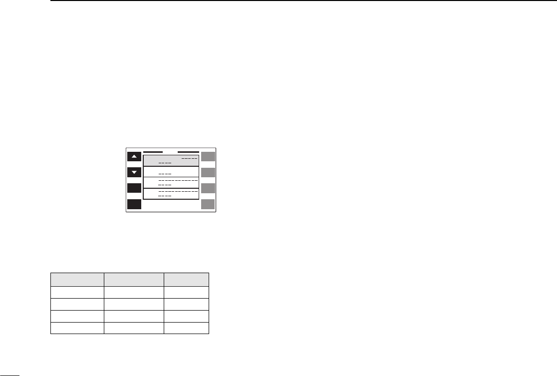
■DTMF speed
The rate at which DTMF memories send individual DTMF
characters can be set to accommodate operating needs.
qPush [DTMF] for 2 sec. to select the DTMF memory
screen.
•Push [CHG/L] if [DTMF] is not displayed.
wPush [TIME] one or more times to select the desired
speed as shown in the table below.
ePush [ï] to exit the DTMF memory screen.
DISPLAY INTERVAL SPEED
100ms 100 msec. 5.0 cps
200ms 200 msec. 2.5 cps
300ms 300 msec. 1.6 cps
500ms 500 msec. 1.0 cps
56
13 DTMF MEMORY
cps=characters/sec.
DTMF
D0
D1
D2
D3
0123456
0123456789
AB
Tx Time
100
ms
TIME
EDIT
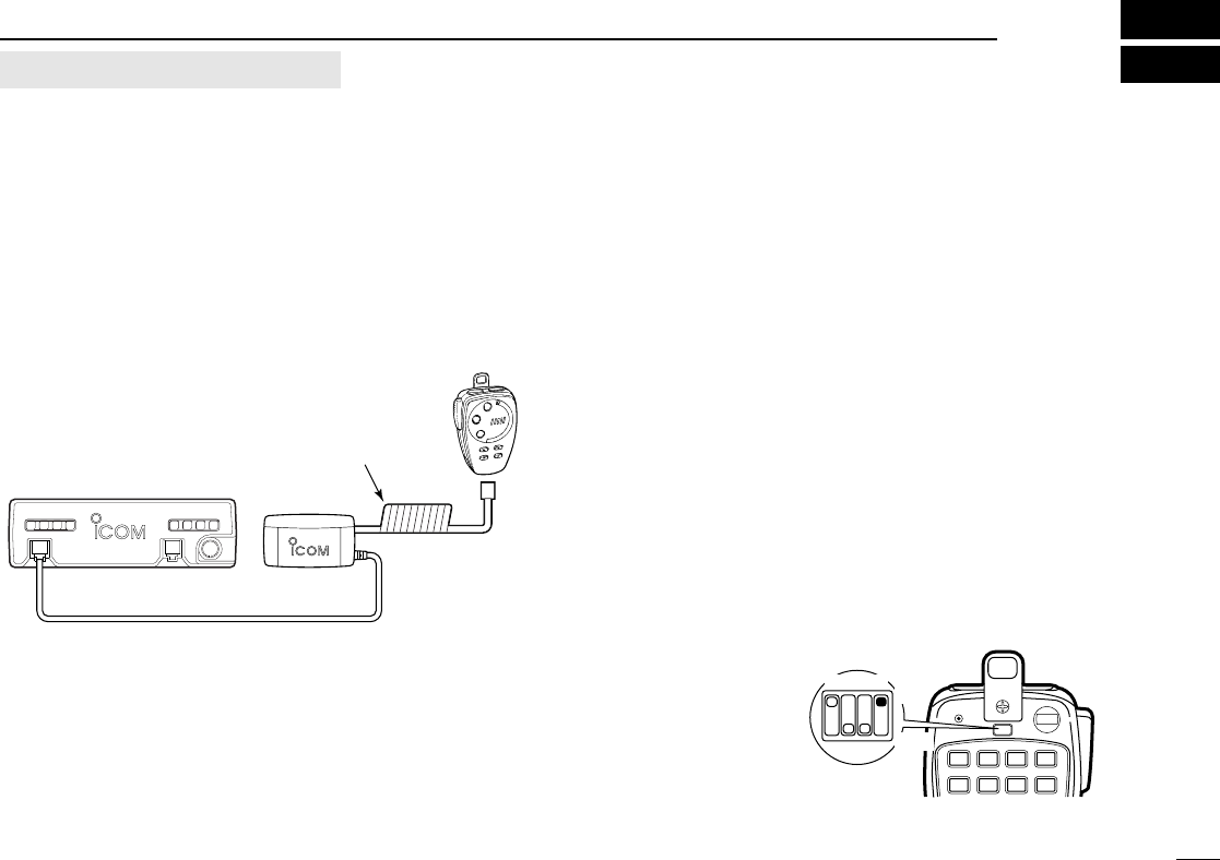
■Connection
Wireless remote control is available when the following op-
tions are used.
➧HM-90
WIRELESS MICROPHONE
➧EX-1759
INFRARED RECEIVER
DRecommended connection
■HM-90 wireless microphone
The HM-90’s internal battery should be charged when the mi-
crophone is not being held.
Charging period : 1.5 hr. with timer
(or 8 hr. when battery is exhausted)
Operating period : 12 hr. (operation:standby=1:4)
DCharging method
Choose one of the following methods:
➥Connect the supplied microphone cable from the HM-90 to
the EX-1759.
➥Connect the supplied microphone cable from the HM-90 to
the main unit.
DTurning the wireless remote ON/OFF
When you use the HM-90 as a wired microphone, the wire-
less remote control circuit can be turned OFF.
57
14
WIRELESS OPERATION
DATA
MIC CONTROLLER
IC-2800H EX-1759
HM-90
Use the microphone cable
for charging
LOCK
AFC AFC-OFF PTT-M MW
PGR
CALL
123A
456B
MR VFO CLR
C-SQL DTMF D-OFF
HIGH MID LOW SET
The diagram shows that
the wireless remote con-
trol function is turned
ON.
Dip switch
1 2 3 4 ON
OFF
optional EX-1759 and HM-90
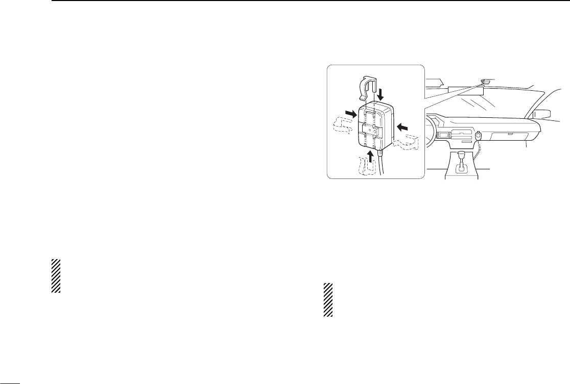
58
14 WIRELESS OPERATION
■EX-1759 installation
The EX-1759
INFRARED RECEIVER
can be installed for 2 differ-
ent purposes depending on the HM-90 charger. This is be-
cause the EX-1759 has both an infrared receiver and a
microphone connector which contains microphone charging
capabilities.
When using the IC-2800H main unit
Attach the EX-1759 to a suitable location for receiving infrared
signals, e.g. sun visor, etc.
When using the connector for a microphone charger
Attach the EX-1759 to a suitable location for receiving infrared
signals and where it can be connected to cable, e.g. the con-
sole, etc.
DO NOT attach the EX-1759 where it will be subject to di-
rect sunlight as it cannot detect infrared signals under such
conditions.
Optional infrared sub receiver
An optional EX-1513
INFRARED SUB RECEIVER
is available to
increase the remote control reliability and extend the control-
lable area. Connect the EX-1513 to the inside connector of
the EX-1759.
The HM-98 can be connected and used with the EX-1759,
however, the optional wireless microphone cannot be used
in such a case.
(When using the
main unit for mic
charging)
(When using the mic
connector for mic
charging.)
The installation clip can be oriented in 1 of 4 ways.
EX-1759
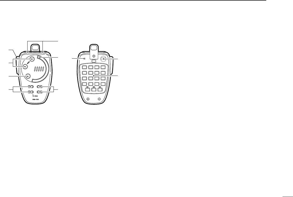
■HM-90 switches
qPTT SWITCH
➥Push and hold to transmit; release to receive.
➥Toggles between transmitting and receiving while the
one-touch PTT function is in use.
wBAND SWITCHES [BAND SELECT YY,ZZ]
➥Push to select the operating band.
➥Activate the sub band access function after pushing
[FUNC] on the HM-90 rear panel.
eMONITOR SWITCH [MONI]
Toggles the monitor function ON and OFF.
rSQUELCH LEVEL UP/DOWN SWITCHES
[YYSQL], [ZZSQL]
Adjust the squelch level.
tFREQUENCY UP/DOWN SWITCHES [UP], [DN]
➥Push either switch to change the operating frequency,
memory channel, set mode contents, etc.
➥Push and hold either switch to start scanning.
yACTIVITY INDICATOR
Lights red while a key is pushed; lights green while the
one-touch PTT function is in use.
uAUDIO VOLUME UP/DOWN SWITCHES
[YYVOL], [ZZVOL]
Adjust the audio output level.
iMODE INDICATOR
Indicates the microphone condition.
•Lights red when [FUNC] is pushed.
•Lights green when [DTMF KEY] is pushed.
•Lights orange when [DTMF MEMO] is pushed.
oLOCK SWITCH [LOCK]
Locks all switches and keys on the microphone except for
the PTT switch.
!0 KEYPAD
Used for controlling the transceiver, transmitting a DTMF
memory channel, etc.
59
14
WIRELESS OPERATION
BAND
SELECT
MONI
REMOTE CONTROL MICROPHONE
VOLSQL
LOCK
JAPAN
AFC AFC-OFF PTT-M MW
PGR
CALL
123A
456B
M0# D
MR VFO CLR
C-SQL DTMF D-OFF
SCAN
MONI
FUNC DTMF
KEY DTMF
MEMO
MUTE SQL ENT
789C
DUP– DUP+SIMP SPCH
PRIO REAR LOCK DEMO
TONE
HIGH MID LOW SET
T-SQLST-SQL T-OFF ➓
➊
➋
➌
➍
➎
➏
➐
➑➒
Front and side panels Rear panel

60
14 WIRELESS OPERATION
KEY FUNCTION
Selects the call channel.
Selects memory mode.
Selects VFO mode.
Selects high output power.
Selects mid-high output power.
Selects low output power.
Selects –duplex.
Selects +duplex.
Selects simplex.
Mutes audio signals.
SECONDARY FUNCTION (after )
No secondary function.
No secondary function.
Turns the one-touch PTT function ON and
OFF.
No secondary function.
No secondary function.
Turns the DTMF memory function ON.
Turns the subaudible tone encoder ON.
Turns the pocket beep function ON.
Turns the tone squelch function ON.
Starts and stops a priority watch.
FUNC
OTHER FUNCTIONS
•After :
Input the appropriate digit
for frequency or memory
channel selection.
•After :
Transmit the appropriate
DTMF code.
•After :
Transmit the appropriate
DTMF memory contents.
[0] to [9], [A] to [D] can be
used for DTMF memory.
DTMF
MEMO
DTMF
KEY
D
ENT
DEMO
AFC
CALL
1
AFC-OFF
2
MR
PTT-M
3
VFO
PGR
4
HIGH
5
C-SQL
MID
6
DTMF
LOW
7
DUP–
TONE
8
DUP+
T-SQLS
9
SIMP
T-SQL
0
MUTE
PRIO

61
14
WIRELESS OPERATION
KEY FUNCTION
Clears a digit before entry.
Cancels the scan, priority watch, or
DTMF memory function.
Enters set mode and advances the set
mode selection order.
Decreases the set mode selection order
after entering set mode.
NOTE:
The IC-2800H has no voice synthesizer
function.
Sets the keypad for numeral input.
Toggles between opening and closing
the squelch.
No function.
SECONDARY FUNCTION (after )
Writes the VFO contents into the mem-
ory channel or call channel.
Advances the memory channel number
when continuously pushed after pro-
gramming is completed.
Turns the DTMF memory function OFF.
Turns the subaudible tone encoder,
pocket beep or tone squelch OFF.
Enters and exits demonstration mode.
Starts and stops scanning.
Locks all the keys on the microphone’s
rear panel.
FUNC
OTHER FUNCTIONS
•After :
Transmit the appropriate
DTMF code.
[BMONI]
Transmits a 1750 Hz tone
call signal for 0.5 sec.
[ASQL]
Transmits a 1750 Hz tone
call signal while pushing.
DTMF
KEY
MW
A
CLR
B
D-OFF
SET
C
SPCH
T-OFF
D
ENT
DEMO
M
SCAN
MONI
#
SQL
REAR LOCK
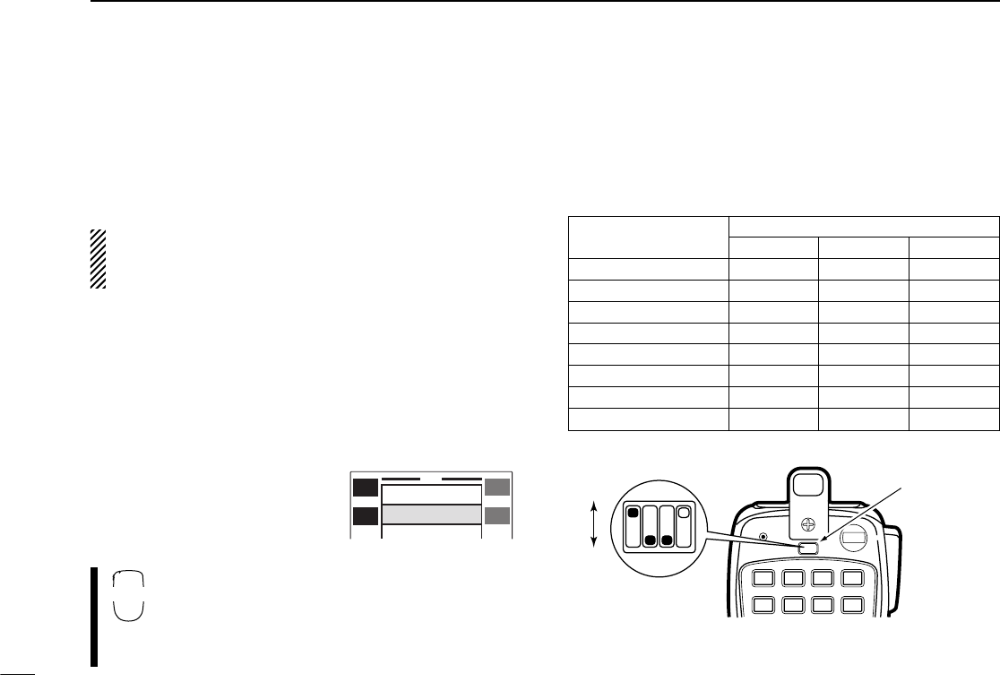
62
14 WIRELESS OPERATION
■Microphone address
The transceiver has 8 possible microphone addresses (in-
cluding OFF) to help prevent interference from other HM-90
wireless microphones. Set both the microphone address and
microphone dip switch to the same value as follows.
When the supplied microphone is connected, the trans-
ceiver rejects control signals from the HM-90 even when
the microphone address is matched.
DMicrophone address
qPush [(DISP)SET] for 2 sec. to enter set mode.
•Push [CHG/L] if [(DISP)SET] is not displayed.
wPush [Y] or [Z] to select the ‘HM-90 Address’ item.
•Left-hand tuning dial can also select the item.
eRotate the right-hand tuning dial to set the microphone ad-
dress to 0–7 or to turn the microphone control OFF.
•When “OFF” is selected, the
transceiver rejects all control sig-
nals from the HM-90.
rPush [ï] to exit set mode.
qPush [FSET]; then push [FSET] or [GENT] to
select the ‘HM-90 Address’ item.
wPush [Y] or [Z] to set the microphone address
to 0–7 or to turn the microphone control OFF.
ePush [ECLR] to exit set mode.
DMicrophone dip switch
qRemove the switch cover from the microphone rear panel.
wSet the microphone dip switch and the microphone ad-
dress to the same value as shown below.
eReplace the switch cover.
MICROPHONE DIP SWITCH
ADDRESS S1-1 S1-2 S1-3
0 OFF OFF OFF
1 (default) ON OFF OFF
2 OFF ON OFF
3ONONOFF
4 OFF OFF ON
5 ON OFF ON
6 OFF ON ON
7ONONON
LOCK
AFC AFC-OFF PTT-M MW
PGR
CALL
123A
456B
MR VFO CLR
C-SQL DTMF D-OFF
HIGH MID LOW SET
Switch cover
Dip switch (S1)
ON
OFF
123
ï
Y
Z
SET
Squelch Delay Long
1
HM-90 Address
Sub Band Mute
SET
B
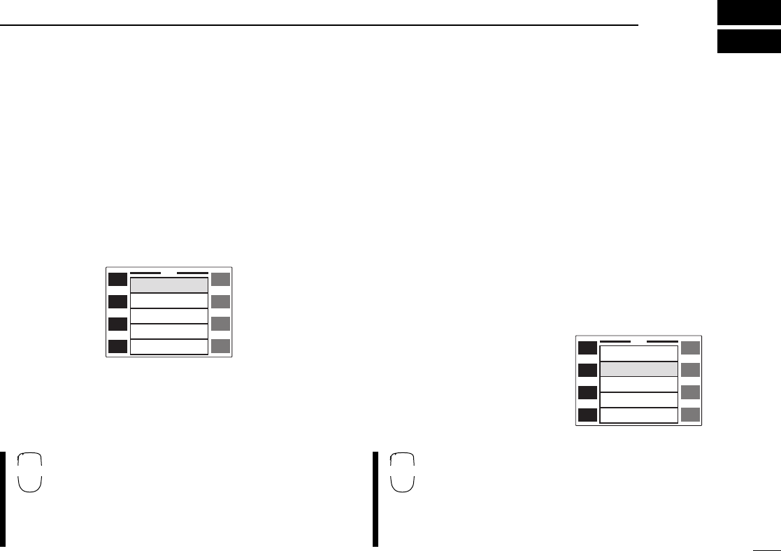
63
15
OTHER FUNCTIONS
■Beep tones
You can select silent operation by turning beep tones OFF or
you can select to have confirmation beeps sound at the push
of a switch by turning beep tones ON.
qPush [(DISP)SET] for 2 sec. to enter set mode.
•Push [CHG/L] if [(DISP)SET] is not displayed.
wPush [Y] to select the ‘Operation Beep’ item.
•Left-hand tuning dial can also select the item.
eRotate the right-hand tuning dial to turn the confirmation
beep ON or OFF.
rPush [ï] to exit set mode.
qPush [FSET] to enter set mode.
wPush [FSET] to select the ‘Operation Beep’
item.
ePush [Y] or [Z] to turn the confirmation beep
ON or OFF.
rPush [ECLR] to exit set mode.
■Time-out timer
To prevent accidental prolonged transmission with the one-
touch PTT function, etc., the transceiver has a time-out timer.
This timer cuts a transmission OFF after 3, 5, 15 or 30 min. of
continuous transmission. This timer can be cancelled (de-
fault).
Approx. 10 sec. before the time-out timer is activated, the
transceiver emits a beep tone as a warning.
qPush [(DISP)SET] for 2 sec. to enter set mode.
•Push [CHG/L] if [(DISP)SET] is not displayed.
wPush [Y] or [Z] to select the ‘Tx T.O.T.’ item.
•Left-hand tuning dial can also
select the item.
eRotate the right-hand tuning
dial to select the desired time-
out time or turn the timer OFF.
rPush [ï] to exit set mode.
qPush [FSET] to enter set mode.
wPush [FSET] or [GENT] to select the ‘Tx
T.O.T.’ item.
ePush [Y] or [Z] to select the desired time-out
time or turn the timer OFF.
rPush [ECLR] to exit set mode.
ï
Y
Z
SET
Operation Beep ON
OFF
OFF
OFF
Auto
Tx T.O.T.
Auto Repeater
Auto Power-Off
Cooling Fan
ï
Y
Z
SET
Operation Beep ON
OFF
OFF
OFF
Auto
Tx T.O.T.
Auto Repeater
Auto Power-Off
Cooling Fan
SET
B
SET
B
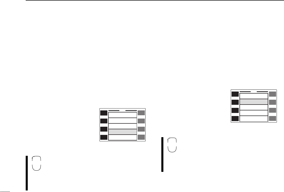
64
15 OTHER FUNCTIONS
■Auto power-off function
The transceiver can be set to automatically turn OFF after a
specified period in which no operations are performed.
2 hours, 1 hour, 30 min. and OFF can be specified. The spec-
ified period is retained even when the transceiver is turned
OFF by the auto power-off function. To cancel the function,
select “OFF” in step ebelow.
qPush [(DISP)SET] for 2 sec. to enter set mode.
•Push [CHG/L] if [(DISP)SET] is not displayed.
wPush [Y] or [Z] to select the ‘Auto Power-Off’ item.
•Left-hand tuning dial can also
select the item.
eRotate the right-hand tuning
dial to select the desired auto
power-off time or turn the
function OFF.
rPush [ï] to exit set mode.
qPush [FSET] to enter set mode.
wPush [FSET] or [GENT] to select the ‘Auto
Power-Off’ item.
ePush [Y] or [Z] to select the desired auto
power-off time or turn the function OFF.
rPush [ECLR] to exit set mode.
■Cooling fan
The transceiver has a heatsink and cooling fan to radiate
heat. The cooling fan automatically turns ON while transmit-
ting and remains ON for 2 min. after transmitting. The cool-
ing fan can be activated continuously, if desired.
qPush [(DISP)SET] for 2 sec. to enter set mode.
•Push [CHG/L] if [(DISP)SET] is not displayed.
wPush [Y] or [Z] to select the ‘Cooling Fan’ item.
•Left-hand tuning dial can also
select the item.
eRotate the right-hand tuning
dial to set the cooling fan to
automatic (“Auto”) or contin-
uous (“ON”).
rPush [ï] to exit set mode.
qPush [FSET] to enter set mode.
wPush [FSET] or [GENT] to select the ‘Cooling
Fan’ item.
ePush [Y] or [Z] to set the cooling fan to auto-
matic (“Auto”) or continuous (“ON”).
rPush [ECLR] to exit set mode.
ï
Y
Z
SET
Operation Beep ON
OFF
OFF
OFF
Auto
Tx T.O.T.
Auto Repeater
Auto Power-Off
Cooling Fan
ï
Y
Z
SET
Auto Power-Off OFF
Auto
1200
Long
1
Cooling Fan
Packet BPS
Squelch Delay
HM-90 Address
SET
B
SET
B
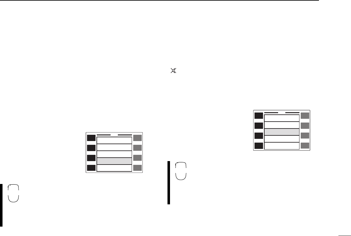
65
15
OTHER FUNCTIONS
■Squelch delay
During operation, received signal strength often fluctuates.
This can result in annoying repeated opening and closing of
the squelch during reception of the same signal. The trans-
ceiver has a built-in squelch delay function which helps pre-
vent this. When both stations are operating from a fixed
location e.g. during packet operation, this function should be
set to “short.”
qPush [(DISP)SET] for 2 sec. to enter set mode.
•Push [CHG/L] if [(DISP)SET] is not displayed.
wPush [Y] or [Z] to select the ‘Squelch Delay’ item.
•Left-hand tuning dial can also
select the item.
eRotate the right-hand tuning
dial to set the squelch delay
to “Long” or “Short.”
rPush [ï] to exit set mode.
qPush [FSET] to enter set mode.
wPush [FSET] or [GENT] to select the ‘Squelch
Delay’ item.
ePush [Y] or [Z] to set the squelch delay to
“Long” or “Short.”
rPush [ECLR] to exit set mode.
■Sub band mute
The sub band mute function automatically cuts out sub band
AF signals when a main band signal is received.
“ ” appears while the sub band mute is activated.
qPush [(DISP)SET] for 2 sec. to enter set mode.
•Push [CHG/L] if [(DISP)SET] is not displayed.
wPush [Y] or [Z] to select the ‘Sub Band Mute’ item.
•Left-hand tuning dial can also
select the item.
eRotate the right-hand tuning
dial to turn the sub band
mute function ON or OFF.
rPush [ï] to exit set mode.
qPush [FSET] to enter set mode.
wPush [FSET] or [GENT] to select the ‘Sub
Band Mute’ item.
ePush [Y] or [Z] to turn the sub band mute
function ON or OFF.
rPush [ECLR] to exit set mode.
ï
Y
Z
SET
Auto Power-Off OFF
Auto
1200
Long
1
Cooling Fan
Packet BPS
Squelch Delay
HM-90 Address
SET
B
ï
Y
Z
SET
Squelch Delay Long
1
OFF
OFF
ON
HM-90 Address
Sub Band Mute
Sub Band Beep
RF Attenuator
SET
B
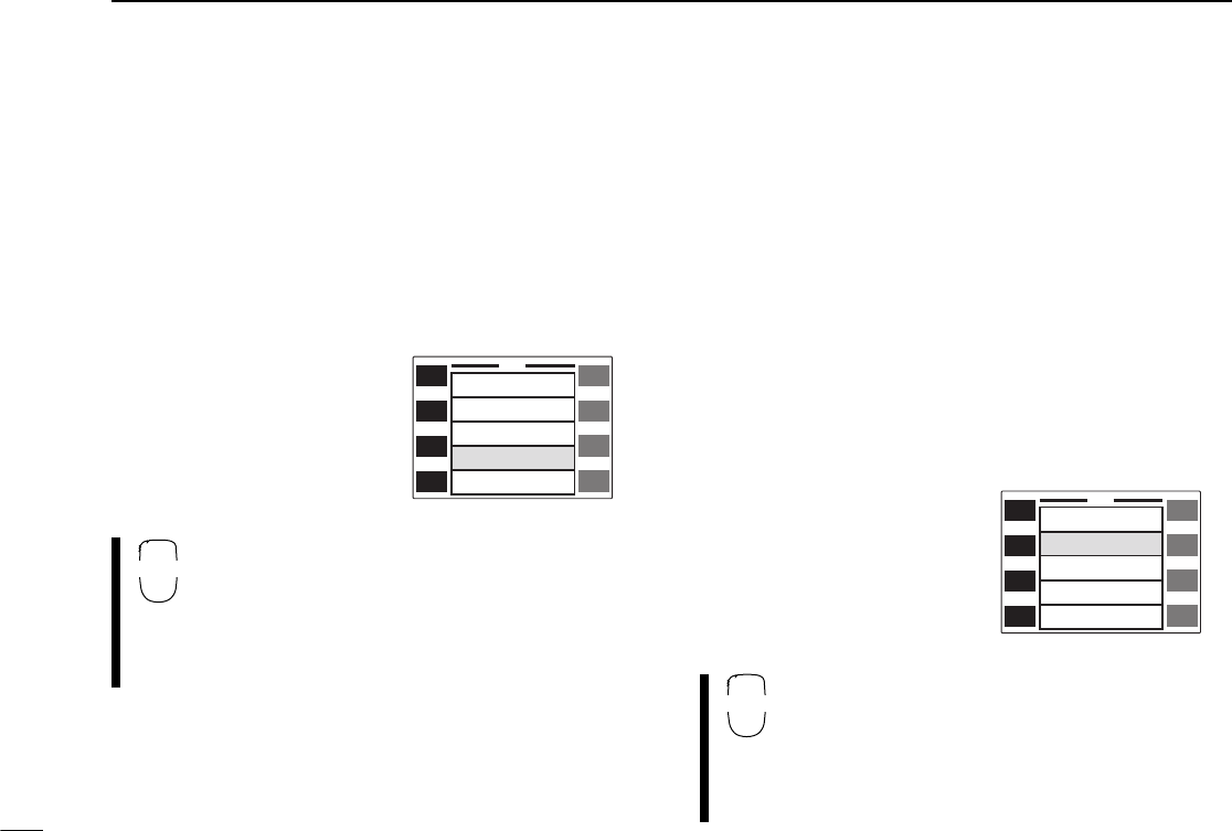
66
15 OTHER FUNCTIONS
■Sub band busy beep
The sub band busy beep sounds when the sub band’s
squelch is closed to inform you that the sub band’s squelch
has been opened.
qPush [(DISP)SET] for 2 sec. to enter set mode.
•Push [CHG/L] if [(DISP)SET] is not displayed.
wPush [Y] or [Z] to select the ‘Sub Band Beep’ item.
•Left-hand tuning dial can also
select the item.
eRotate the right-hand tuning
dial to turn the sub band
busy beep ON or OFF.
rPush [ï] to exit set mode.
qPush [FSET] to enter set mode.
wPush [FSET] or [GENT] to select the ‘Sub
Band Beep’ item.
ePush [Y] or [Z] to turn the sub band busy beep
ON or OFF.
rPush [ECLR] to exit set mode.
■Automatic RF attenuator
The attenuator prevents a desired signal from distorting when
very strong signals are near the desired frequency, etc.
The transceiver’s RF attenuator is linked to the [SQL] setting.
The attenuator is automatically activated when [SQL] is ro-
tated clockwise past the 12 o’clock position. Approx. 10 dB at-
tenuation is obtained at full rotation. This function can be
turned ON or OFF in set mode.
qPush [(DISP)SET] for 2 sec. to enter set mode.
•Push [CHG/L] if [(DISP)SET] is not displayed.
wPush [Y] or [Z] to select the ‘RF Attenuator’ item.
•Left-hand tuning dial can also
select the item.
eRotate the right-hand tuning
dial to turn the automatic
RF attenuator ON or OFF.
rPush [ï] to exit set mode.
qPush [FSET] to enter set mode.
wPush [FSET] or [GENT] to select the ‘RF At-
tenuator’ item.
ePush [Y] or [Z] to turn the automatic RF atten-
uator ON or OFF.
rPush [ECLR] to exit set mode.
ï
Y
Z
SET
Squelch Delay Long
1
OFF
OFF
ON
HM-90 Address
Sub Band Mute
Sub Band Beep
RF Attenuator
SET
B
ï
Y
Z
SET
Sub Band BeepOFF
OFF
OFF
VHF M/C
UHF M/C
RF Attenuator
Memory Name
HM-98 F-1
HM-98 F-2
SET
B
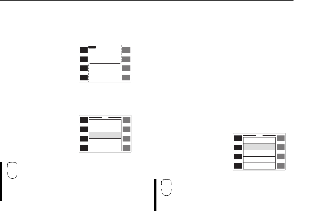
67
15
OTHER FUNCTIONS
■Memory name indication
The transceiver can display
memory names programmed
in memory or call channels. (p.
32)
qPush [(DISP)SET] for 2 sec. to enter set mode.
•Push [CHG/L] if [(DISP)SET] is not displayed.
wPush [Y] or [Z] to select the ‘Memory Name’ item.
•Left-hand tuning dial can also
select the item.
eRotate the right-hand tuning
dial to turn the memory
name indication ON or OFF.
rPush [ï] to exit set mode.
qPush [FSET] to enter set mode.
wPush [FSET] or [GENT] to select the ‘Memory
Name’ item.
ePush [Y] or [Z] to turn the memory name indi-
cation ON or OFF.
rPush [ECLR] to exit set mode.
■HM-98 [F-1]/[F-2] keys
Switches on the transceiver’s front panel can be assigned to
the HM-98 [F-1] and [F-2] keys. The following can be as-
signed:
V/U MAIN : [MAIN(SCP)] V/U V/MHz : [V/M
H
(TS)]
V/U M/C : [M/C(SCN)] V/U MONI : [MONI(LOW)]
V/U EDIT : [MAIN(EDIT)] V/U TONE : [TON(DUP)]
V/U MW : [S.MW(MW)] DTMF : [DTMF]
DISP : [DISP(SET)] Up : Microphone’s up
Dn : Microphone’s down
qPush [(DISP)SET] for 2 sec. to enter set mode.
•Push [CHG/L] if [(DISP)SET] is not displayed.
wPush [Y] or [Z] to select the ‘HM-98 F-1’ or ‘F-2’ item.
•Left-hand tuning dial can also
select the item.
eRotate the right-hand tuning
dial to select the desired
function.
rPush [ï] to exit set mode.
qPush [FSET] to enter set mode.
wPush [FSET] or [GENT] to select the ‘HM-98
F-1’ or ‘F-2’ item.
ePush [Y] or [Z] to select the desired function.
rPush [ECLR] to exit set mode.
ï
Y
Z
SET
Sub Band BeepOFF
OFF
OFF
VHF M/C
UHF M/C
RF Attenuator
Memory Name
HM-98 F-1
HM-98 F-2
ï
Y
Z
SET
Memory Name OFF
VHF M/C
UHF M/C
Up
Dn
HM-98 F-1
HM-98 F-2
HM-118 Up
HM-118 Dn
12
EDIT
MAIN
DUP
TON
MID-LO
DISP
SET
MW
S.MW
EDIT
MW
S.MW
EDIT
MAIN
DUP
TON
ICOM2800
14
5.320
MAIN
MID-LO
12
43
3.000
JA3YUA
SET
B
SET
B
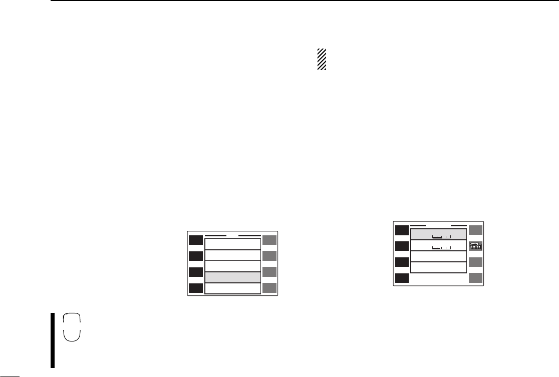
68
15 OTHER FUNCTIONS
■HM-97/118 [UP]/[DN] keys
Switches on the transceiver’s front panel can be assigned to
the HM-97/118 [UP] and [DN] keys. The following can be as-
signed:
V/U MAIN : [MAIN(SCP)] V/U V/MHz : [V/M
H
(TS)]
V/U M/C : [M/C(SCN)] V/U MONI : [MONI(LOW)]
V/U EDIT : [MAIN(EDIT)] V/U TONE : [TON(DUP)]
V/U MW : [S.MW(MW)] DTMF : [DTMF]
DISP : [DISP(SET)] Up : Microphone’s up
Dn : Microphone’s down
qPush [(DISP)SET] for 2 sec. to enter set mode.
•Push [CHG/L] if [(DISP)SET] is not displayed.
wPush [Y] or [Z] to select the ‘HM-118 Up’ or ‘Dn’ item.
•Left-hand tuning dial can also
select the item.
eRotate the right-hand tuning
dial to select the desired
function.
rPush [ï] to exit set mode.
qPush [FSET] to enter set mode.
wPush [FSET] or [GENT] to select the ‘HM-118
Up’ or ‘Dn’ item.
ePush [Y] or [Z] to select the desired function.
rPush [ECLR] to exit set mode.
[UP] or [DN] key assignment is available for the micro-
phones which have [UP]/[DN] switches except the HM-98.
■Display contrast
The contrast of the LCD can be adjusted from 0% to 100% in
3 or 4% steps. Adjust contrast to suit lighting conditions and
personal preferences.
qPush [DISP] to enter display set mode.
•Push [CHG/L] if [DISP] is not displayed.
wPush [Y] to select the ‘Contrast’ item.
•Left-hand tuning dial can also select the item.
eRotate the right-hand tuning dial to select the desired con-
trast.
rPush [ï] to exit display set mode.
ï
Y
Z
SET
Memory Name OFF
VHF M/C
UHF M/C
Up
Dn
HM-98 F-1
HM-98 F-2
HM-118 Up
HM-118 Dn
ï
Y
Z
DISPLAY
Contrast 50%
38%
Bright
My Call
Display Type A
SET
B
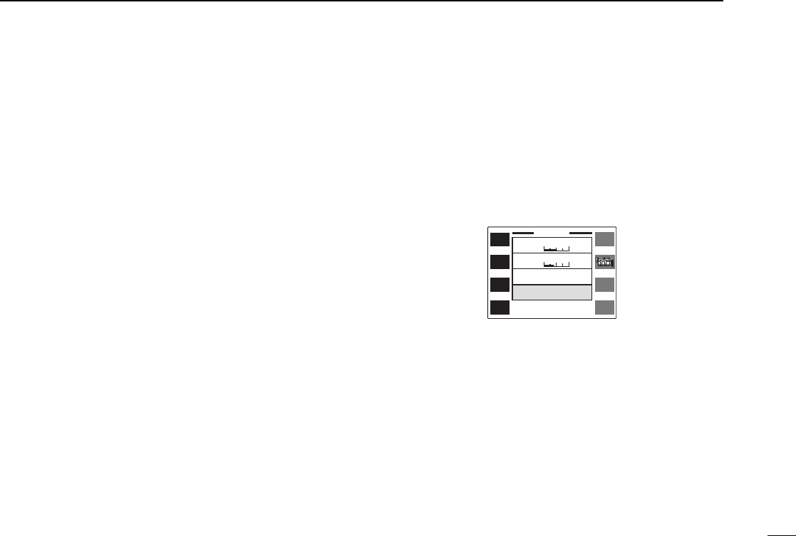
69
15
OTHER FUNCTIONS
■Display brightness
The brightness of the LCD can be adjusted from 0% to 100%
in 3 or 4% steps. Adjust brightness to suit lighting conditions
and personal preferences.
qPush [DISP] to enter display set mode.
•Push [CHG/L] if [DISP] is not displayed.
wPush [Y] or [Z] to select the ‘Bright’ item.
•Left-hand tuning dial can also select the item.
eRotate the right-hand tuning dial to select the desired
brightness.
rPush [ï] to exit display set mode.
■Indication type
The indication type can be selected from 4 types.
qPush [DISP] to enter display set mode.
•Push [CHG/L] if [DISP] is not displayed.
wPush [Y] or [Z] to select the ‘Display Type’ item.
•Left-hand tuning dial can also select the item.
eRotate the right-hand tuning dial to select the desired indi-
cation type.
rPush [ï] to exit display set mode.
■My call function
The opening title when turning power ON can be changed to
your call sign, etc. Up to 8 characters can be programmed.
qPush [DISP] to enter display set mode.
•Push [CHG/L] if [DISP] is not displayed.
wPush [Z] to select the ‘My Call’ item.
•Left-hand tuning dial can also select the item.
ePush [EDIT] to enter programming mode.
•The first character of the name flashes.
rRotate the right-hand tuning dial to select the desired char-
acter.
•A to Z, 0 to 9, – (hyphen) and space are available.
tPush [≈] to advance to the next character.
•Push [Ω] to select the previous character.
yRepeat rand tuntil the desired name is input.
uPush [ï] to program the name and exit programming
mode.
iPush [ï] again to exit display set mode.
ï
Y
Z
DISPLAY
Contrast 50%
Bright
My Call
Display Type A
EDIT
38%
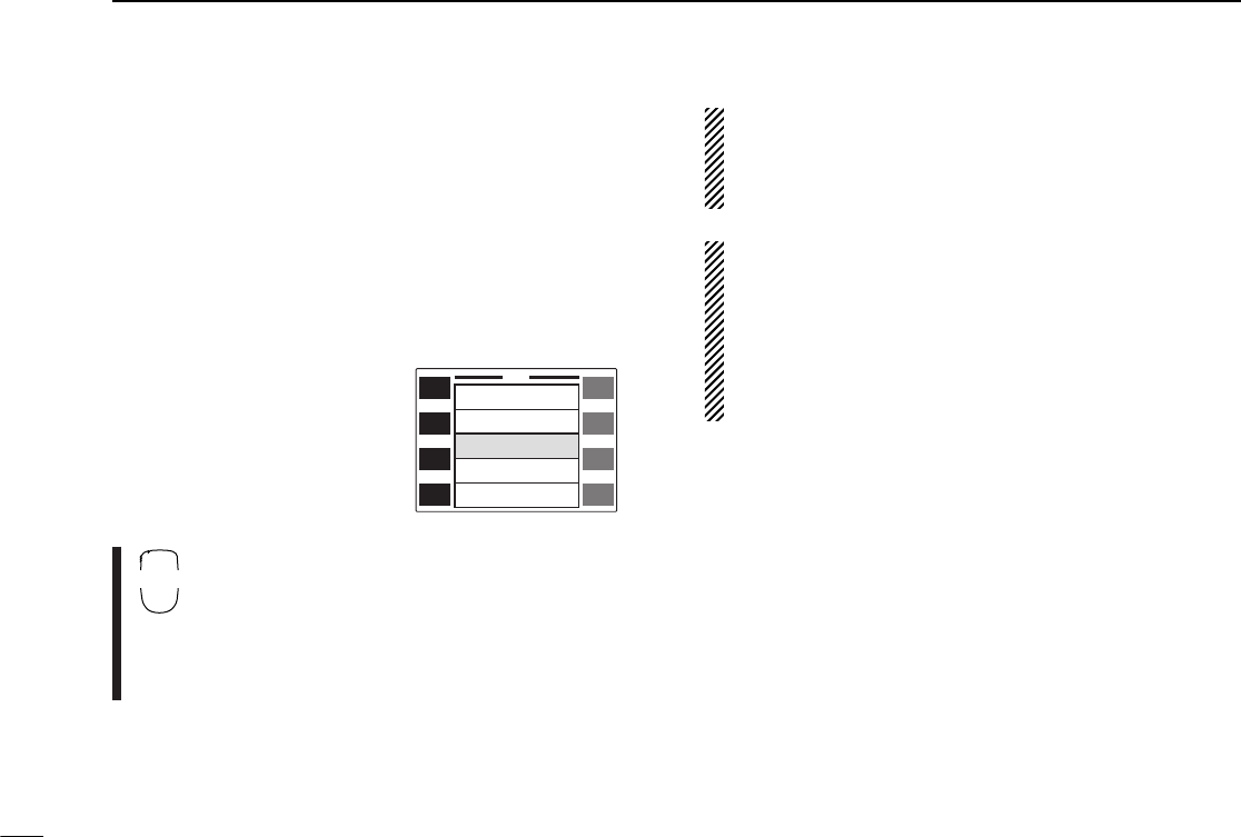
70
15 OTHER FUNCTIONS
■Packet operation
DData speed
For packet operation, the transceiver can be set to one of two
data speeds: 1200 bps (default) or 9600 bps.
qPush [(DISP)SET] for 2 sec. to enter set mode.
•Push [CHG/L] if [(DISP)SET] is not displayed.
wPush [Y] or [Z] to select the ‘Packet BPS’ item.
•Left-hand tuning dial can also
select the item.
eRotate the right-hand tuning
dial to select the desired
data speed.
rPush [ï] to exit set mode.
qPush [FSET] to enter set mode.
wPush [FSET] or [GENT] to select the ‘Packet
BPS’ item.
ePush [Y] or [Z] to select the desired data
speed.
rPush [ECLR] to exit set mode.
For 1200 bps operation—
•Disconnect the microphone plug from the microphone
connector during data transmission, otherwise the data
signal and voice signal are simultaneously transmitted.
For 9600 bps operation—
•When the transceiver is set for 9600 bps data transmis-
sion in set mode, the microphone signal is automatically
cut. Therefore, it is not necessary to disconnect the mi-
crophone plug from the connector in this case.
•When pushing [PTT] during data transmission, data trans-
mission is interrupted and voice signals have priority.
ï
Y
Z
SET
Auto Power-Off OFF
Auto
1200
Long
1
Cooling Fan
Packet BPS
Squelch Delay
HM-90 Address
SET
B
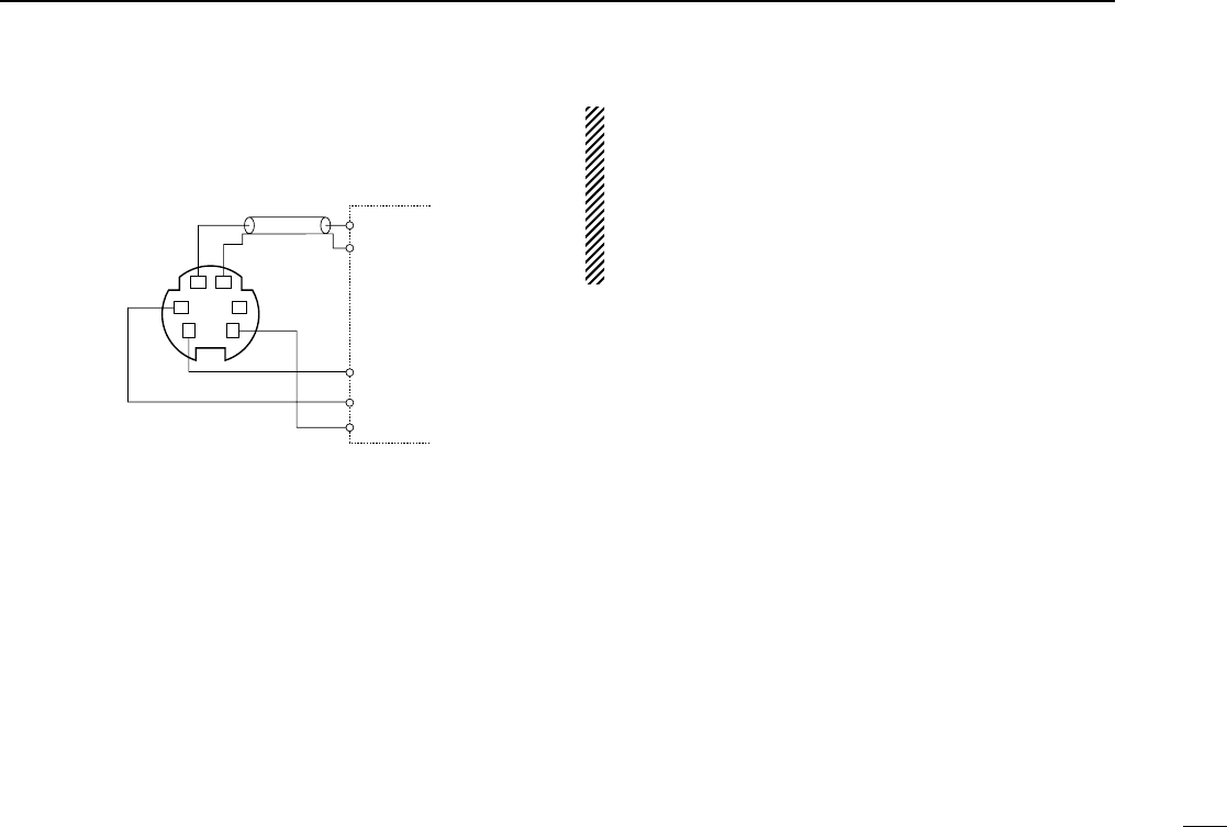
71
15
OTHER FUNCTIONS
D1200 bps packet operation
qConnect the transceiver and a TNC as illustrated below.
wSet the TNC for transmit.
eSet transmit delay on the TNC to 30–50.
rAdjust the TNC frequency deviation if necessary.
•
When using a deviation meter:
Adjust the output of the TNC so that frequency deviation
is in the range ±3 to 4 kHz.
•
When NOT using a deviation meter:
A receiver or transceiver is needed to monitor the trans-
mission—compare the received audio output level when
receiving a TNC modulated signal with high level voice
signals using the microphone.Then adjust the TNC mod-
ulated signal to a lower level than the voice modulated
signal.
•Read the instructions supplied with your TNC carefully be-
fore attempting packet operation with the transceiver.
•Pin tAF OUT is for 1200 bps operation only. This pin
cannot be used for 9600 bps operation.
•Over modulation may degrade signal quality. If you find
that many transmissions are failing, re-adjust the modula-
tion level.
SQL
PTT
RX AUDIO
GND
TX AUDIO
TNC side
q DATA IN
w GND
e PTT P
t AF OUT
y P SQL
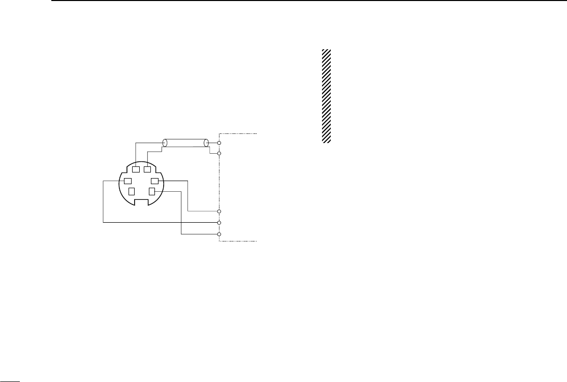
72
15 OTHER FUNCTIONS
D9600 bps high speed packet operation
The transceiver supports 2 modes of 9600 bps packet opera-
tion: G3RUH and GMSK.
qConnect the transceiver and a TNC as illustrated below.
wG3RUH mode can handle 16 kinds of modulated wave
forms in order to maintain a communication link.
eSet transmit delay on the TNC to 30–50.
rAdjust the TNC frequency deviation if necessary (see page
at right).
•When using the PTTP terminal for packet operation, no
voice signals are transmitted from the microphone.
•When pushing [PTT] during data transmission, data trans-
mission is interrupted and the voice signal takes priority.
•Read the instructions supplied with your TNC carefully be-
fore attempting packet operation with the transceiver.
•Pin rDATA OUT is for 9600 bps operation only. This pin
cannot be used for 1200 bps operation.
TNC side
SQL
PTT
RX AUDIO
GND
TX AUDIO
q DATA IN
w GND
e PTT P r DATA OUT
y P SQL
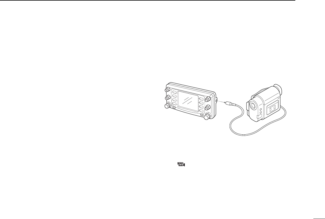
73
15
OTHER FUNCTIONS
DAdjusting the transmit signal output from
the TNC
When setting data transmission speed to 9600 bps, the data
signal coming from the TNC is applied exclusively to the in-
ternal limiter circuitry to automatically maintain band width.
NEVER apply data levels from the TNC of over 0.6 Vp-p, oth-
erwise the transceiver will not be able to maintain the band
width and may possibly interfere with other stations.
1.When using a level meter or synchroscope, adjust the
TX audio output level (DATA IN level) from the TNC as
follows.
0.4 Vp-p (0.2 Vrms) : recommended level
0.2 Vp-p–0.5 Vp-p (0.1 Vrms–0.25 Vrms) : acceptable level
2.When NOT using a measuring device.
qConnect the transceiver to a TNC.
wEnter a test mode (“CAL”, etc.) on the TNC, then transmit
some test data.
e
When the transceiver fails to transmit the test data or trans-
mits sporadically (TX indicator doesn’t appear or flashes):
- Decrease the TNC output level until the transmit indicator
lights continuously.
When transmission is not successful even though the TX
indicator lights continuously:
- Increase the TNC output level.
■Video monitor function
The LCD can be used as a video monitor for an NTSC or PAL
video signal.
NTSC : U.S.A., Australia, Asia, Latin America, Korea and
Taiwan versions
PAL : Europe and Italy versions
qPush [DISP] to enter display set mode.
•Push [CHG/L] if [DISP] is not displayed.
wPush [ ] to monitor a video signal.
•The video signal is displayed on the LCD.
ePush any switch except [POWER] to return to display set
mode.
rPush [ï] to exit display set mode.
to
[VIDEO IN]
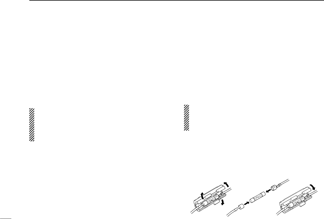
74
15 OTHER FUNCTIONS
■Demonstration display
A demonstration function is available at power ON. This func-
tion gives you a quick visual introduction to the function dis-
play indicators.
qWhile pushing [CHG/L], push [POWER] to turn power ON.
•The transceiver cycles through a visual tour of the function dis-
play indicators.
wPush any switch to exit demonstration mode and enter the
normal operating condition temporarily.
The transceiver automatically returns to demonstration
mode after 2 min. in which no operations are performed.
To deactivate the demonstration display permanently, turn
power OFF, then while pushing [CHG/L], turn power ON
again.
■AM/FM narrow mode
FM narrow mode is only available for the Europe and Italy ver-
sions. AM mode (receive only) is only available for the U.S.A.
and S. America versions. Typically, AM mode is used for the
air band (118–135.995 MHz).
When pushing [PTT], a beep tone sounds indicating the
mode is AM mode. The transceiver cannot transmit in AM
mode.
qSelect the mode/channel you wish to set the mode to, such
as VFO mode or memory/call channel.
wPush the desired band’s [(MAIN)EDIT] for 2 sec. to enter the
edit screen.
•Push [CHG/L] if [(MAIN)EDIT] is not displayed.
ePush [MODE] to set the mode to FM wide/FM narrow or
AM/FM wide.
rIf you want to set other channels, rotate the right-hand tun-
ing dial. Repeat eto select the desired frequency.
tPush [ï] to exit the edit screen.
The Europe and Italy versions of the IC-2800H comply with
European regulations regarding narrow FM bandwidth op-
eration on amateur transceivers. Wide and narrow FM op-
eration differ in specifications.
■Fuse replacement
If the fuse blows or the transceiver stops functioning, find the
source of the problem if possible, and replace the damaged
fuse with a new, rated one (FGB 20 A) as shown below.
20 A
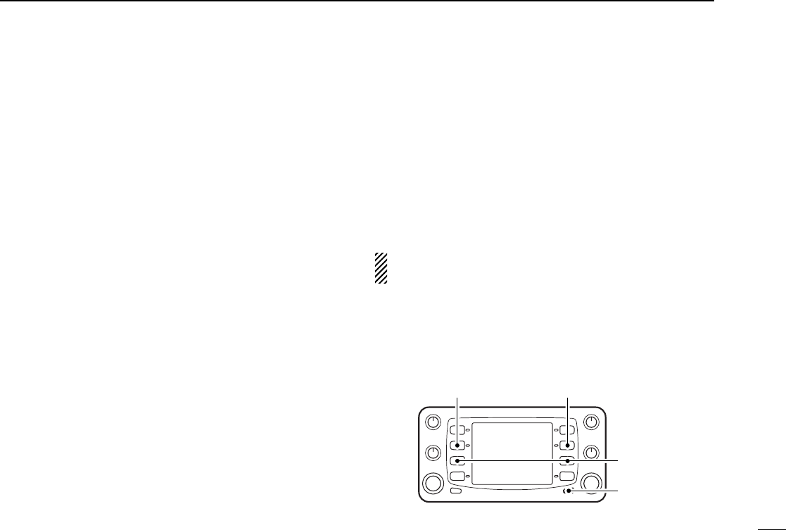
75
15
OTHER FUNCTIONS
■Partial reset
If you want to initialize the operating conditions (VFO fre-
quency, VFO settings, set mode contents) without clearing the
memory contents, a partial resetting function is available for
the transceiver.
Band conditions can be reset independently.
DVHF band partial resetting
➥While pushing the 2nd switch from the top on the left side,
turn power ON to partially reset the transceiver.
•“144M VFO Clear” appears when resetting the VHF band condi-
tion.
DUHF band partial resetting
➥While pushing the 2nd switch from the top on the right side,
turn power ON to partially reset the transceiver.
•“430M (440M) VFO Clear” appears when resetting the UHF band
condition.
DPartial resetting of both bands
➥While pushing the 2nd switches from the top on both the
left and right sides, turn power ON to partially reset the
transceiver.
•“VFO Clear” appears when resetting the VHF and UHF band
condition.
■All reset
The function display may occasionally display erroneous in-
formation (e.g. when first applying power). This may be
caused externally by static electricity or by other factors.
If this problem occurs, turn power OFF. After waiting a few
seconds, turn power ON again. If the problem persists, per-
form the following procedure.
•Partial resetting is also available. See previous section for details.
CAUTION: Resetting the transceiver CLEARS all mem-
ory information and initializes all values in the transceiver.
➥While pushing the 3rd switches from the top on both the left
and right sides, turn power ON to reset the CPU.
•“Memory Clear” appears when resetting the CPU.
[POWER]
All reset
UHF partial
reset
VHF partial
reset
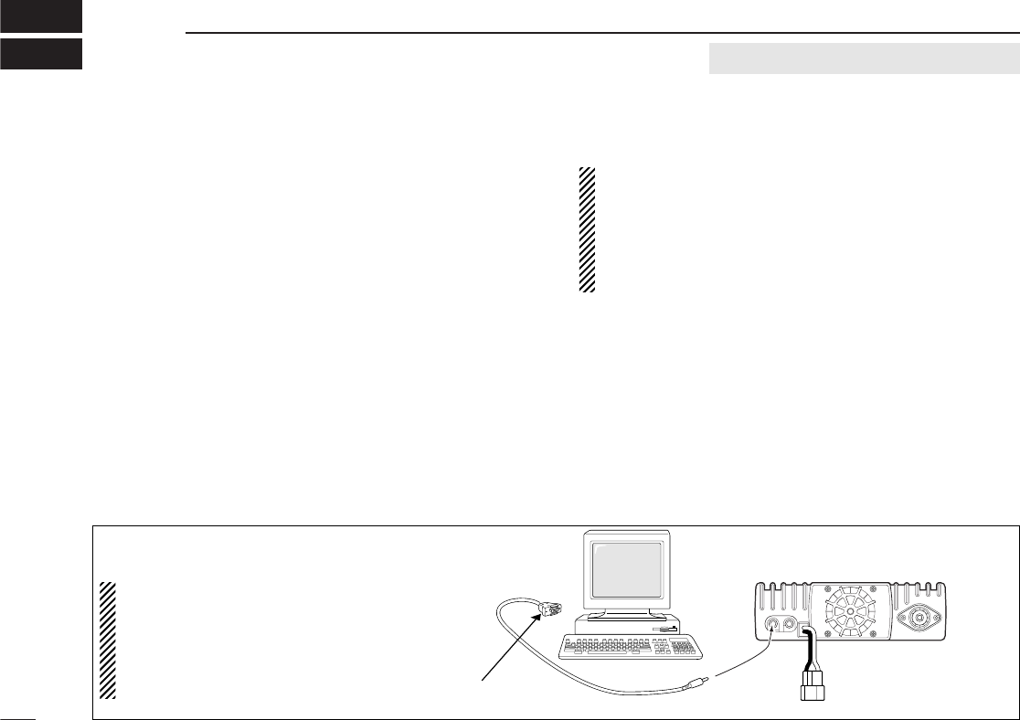
■Getting started
DThis cloning software is designed to perform data setting
and cloning for the IC-2800H DUAL BAND FM transceiver.
DHELP WINDOW: Each item has a help window to describe
functions and operation.
■System requirements
To use this program, the following hardware and software are
required:
•IBM PC/AT compatible computer
•An RS-232C serial port
•Microsoft®Windows®95 or Microsoft®Windows®98
•Intel i486DX4 processor or faster
•At least 16 MB RAM
•At least 640 ×480 pixel display
•OPC-478 CLONING CABLE
■Software installation
NOTE: Before using the program, make a backup copy of
the original disk. After making a backup copy, keep the
original disk in a safe place.
NOTE: Depending on your Windows®system files, the PC
may require rebooting. In this case, repeat the installation
from the beginning.
qBoot up Windows.
•Quit all applications when Windows is running.
wInsert backup disk into the appropriate floppy drive.
eSelect ‘Run’ from the [Start] menu.
rType the setup program name with full path name, then
press the [Enter] key. (A:\SETUP [Enter])
tFollow the prompts.
yProgram group ‘CS-2800’ appears in the ‘Programs’ folder
of the start menu.
76
16 CS-2800 CLONING SOFTWARE optional CS-2800 and OPC-478
IC-2800H
To [430(440)
MHz SP]
to an RS-232C
port
DB9 female plug
(incl. level converter circuit)
Personal
computer
OPC-478
■Connections
All cloning operations are performed from
the computer’s keyboard—the operation re-
quired on the transceiver side is:
while pushing the microphone [UP] switch +
the 4th switch from the top on the left side,
push [POWER] on the controller.
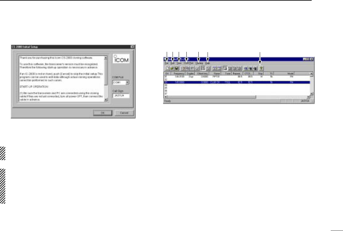
■COM port/call sign setting
•Set the com port (RS-232C port) number properly.
•Enter your call sign.
NOTE: ‘Check the following’ dialog box appears when the
RS-232C serial port is not set correctly.
NOTE: When first using this software, read out all the
transceiver cloning data into the PC before starting editing
with this cloning software. Otherwise the cloning data may
not be cloned properly to the transceiver. (e.g. operating
frequency setting, mode selection, etc.)
■
Memory channel list description
qFILE MENU [File]
Used for turning the software on/off, saving memory chan-
nel contents or quitting the program, etc.
wEDIT MENU [Edit]
The memory channel can hold up to 99 channels + 3 pairs
of programmed scan edges + 1 call channel.
Each memory channel can be edited (copy, paste, clear,
insert and delete) via the edit menu.
eVIEW MENU [View]
•UHF memory channel list, VHF memory channel list,
DTMF autodial, Common settings (p. 79) screens are se-
lectable.
•Turn the tool bar or status bar on/off.
rCOM PORT MENU [COM Port]
Push to display the COM port setting dialog box.
77
16
CS-2800 CLONING SOFTWARE
q w e rtyu
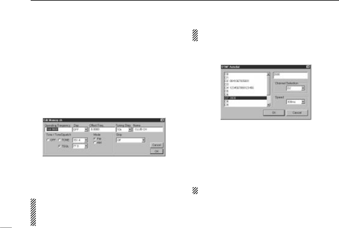
tCLONING MENU [Cloning]
Push to display cloning menu and cloning information dia-
log box.
yHELP MENU [Help]
Push to display one point help, help contents, cloning soft-
ware revision information.
uTool bar
Short cut key appears on the tool bar when clicking the tool
bar function in the [View] menu.
■Edit menu
The ‘Edit Memory ch’ window allows you to edit the memory
channel information.
The memory channel list can hold up 99 channels + 3 pairs of
programmed scan edges + 1 call channel.
NOTE: ‘Narrow FM’ is available for the VHF band of the
Europe and Italy versions only.
NOTE: Read all the transceiver cloning data into the PC
before starting editing with this cloning software, otherwise
the frequency data may not be cloned properly to your
transceiver.
■DTMF autodial
The transceiver has 14 DTMF memory channels (D0–D9,
DA–DD) for storage of often-used DTMF codes of up to 16
digits. One of these channels is encoded when the PTT is
pushed.
When slow DTMF speeds are required, the transceiver’s rate
of DTMF transmission can be adjusted.
“E” stands for “M” and “F” stands for “#.”
78
16 CS-2800 CLONING SOFTWARE
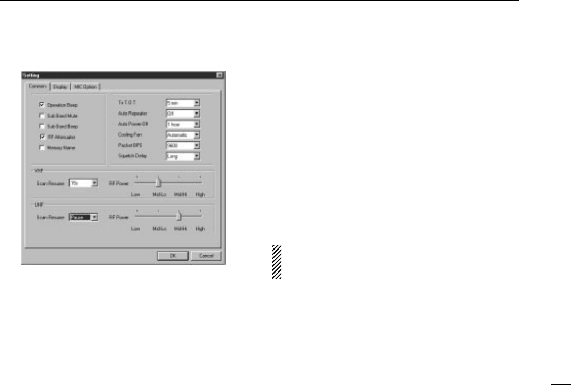
■Common settings
There are 3 setting menus available.
Common : Commonly set items such as operation
beeps, sub band mute, sub band beep, RF
attenuator, name display, TOT, auto repeater,
auto power-off, cooling fan setting, packet
data speed, squelch delay, VHF/UHF scan re-
sume timer and RF output power settings.
Display : Sets LCD contrast and brightness.
Select display type. Enter ‘Opening Title’ and
clone ‘Comment.’
MIC Option : Switches on the transceiver’s front panel can
be assigned to the microphone’s [F-1]/[F-2]
for the HM-98 and [UP]/[DN] for the HM-97
and HM-118/T/TA.
■Exiting cloning mode
➥After cloning is finished, push the [UP]/[DN] or [Y]/[Z] on
the microphone to exit the cloning mode and to return to
normal operating condition.
•The [POWER] switch does not function in the cloning mode.
DO NOT disconnect the controller cable while in the
cloning mode.The transceiver remains in the cloning mode
and continues in power ON condition.
79
16
CS-2800 CLONING SOFTWARE

80
17 TROUBLESHOOTING
PROBLEM POSSIBLE CAUSE SOLUTION REF.
No power comes on. •Power connector has a poor contact.
•Polarity of the power connection is reversed.
•Blown fuse.
•Check the connector pins.
•Reconnect the power cable observing the
proper polarity. Replace the fuse, if damaged.
•Check the cause, then replace the fuse.
—
pgs.
15, 74
p. 74
No sound comes from the
speaker.
•Volume level is too low.
•The squelch level is set too tight.
•A selective call or squelch function is activated
such as tone squelch or pocket beep.
•Rotate [VOL] clockwise.
•Open the squelch.
•Turn the appropriate function OFF.
p. 23
p. 23
pgs.
50, 52
Sub band signals are not
audible.
•The sub band mute function is activated. •Turn the function OFF. p. 65
No contact possible with an-
other station.
•The transceiver is set to semi-duplex.
•The other station is using tone squelch. •Set to simplex.
•Turn OFF tone squelch.
p. 26
p. 50
Repeater cannot be ac-
cessed.
•Wrong offset frequency is programmed.
•Wrong subaudible tone frequency is programmed. •Correct the offset frequency.
•Correct the subaudible tone frequency.
p. 30
p. 29
Frequency cannot be set. •The frequency lock function is activated.
•Priority watch is paused on the watching fre-
quency.
•Turn the function OFF.
•Push [(PRO)PRIO] or [(MEM)PRIO] to resume
the watch.
p. 19
p. 48
Scan does not operate. •Squelch is open.
•The selected programmed scan edge memory
channels (e.g. 1A/1B) have the same frequencies.
•Only 1 memory channel is programmed or other
channels are set as skip channels.
•Set the squelch to the threshold point.
•Reset the scan edges.
•Program other memory channels or cancel the
memory skip function in the desired channels.
p. 23
p. 44
pgs.
50, 52
Transmission is automati-
cally cut off.
•Time-out timer is activated. •Set the timer to OFF. p. 63
Transmission continues
even when PTT is released.
•One-touch PTT function is activated. •Turn the function OFF. p. 25
If your transceiver seems to be malfunctioning, please check
the following points before sending it to a service center.

HM-90 WIRELESS MICROPHONE
Infrared, full remote control microphone. Wired remote control is also
possible.
EX-1759 INFRARED RECEIVER
Used to receive control signals from the HM-90.
EX-1513 INFRARED SUB RECEIVER
Used with the EX-1759 to extend the controllable area.
HM-98 REMOTE CONTROL MICROPHONE
Wired remote control microphone with key backlight. Same as sup-
plied with some versions.
HM-118 HAND MICROPHONE
HM-118T/TA DTMF MICROPHONE
HM-95 DTMF MICROPHONE
HM-97 HAND MICROPHONE (with tone call)
HS-62 FLEXIBLE MOBILE MICROPHONE + HS-15SB SWITCH
BOX + OPC-589 ADAPTER CABLE
For all-around mobile operation.
MB-17A MOBILE MOUNTING BRACKET
One-touch bracket. Transceiver body easily attached and removed.
MB-65 MOUNTING BASE
Mounts the controller unit in a convenient location. Adjustable angle
and direction for optimum positioning.
MB-73 CONTROLLER BRACKET
Mounts the controller to a wall or flat surface. Same as supplied.
SP-10 EXTERNAL SPEAKER
For all-around mobile operation.
CS-2800 CLONING SOFTWARE + OPC-478 CLONING CABLE
Provides quick and easy programming of items, including memory
channels, memory names and set mode contents for local repeater
frequencies, etc. via a PC.
OPC-346/OPC-347 DC POWER CABLES (20 A capacity)
OPC-346: 3.0 m (9.8 ft); OPC-347: 7.0 m (23 ft)
OPC-440/OPC-647 MICROPHONE EXTENSION CABLES
OPC-440: 5.0 m (16.4 ft); OPC-647: 2.5 m (8.2 ft)
OPC-872 CONTROLLER EXTENSION CABLE (3.5 m; 11.5 ft)
81
18
OPTIONS

82
19 SPECIFICATIONS
DGeneral
•Frequency coverage : (Unit: MHz)
U.S.A. Transmit 144–148, 430–450*1
Receive 118–174*2, 430–450*1
S. America Transmit 144–148, 430–440
Receive 118–174*2, 400–530*3
Europe, Tx/Rx 144–146, 430–440
Taiwan
Italy Transmit 144–148, 430–440
Receive 136–174*2, 400–530*3
Asia Transmit 144–148, 430–440
Receive 136–174*2, 430–440
*1Specifications guaranteed 440–450 MHz.
*2Specifications guaranteed 144–148 MHz.
*3Specifications guaranteed 430–440 MHz.
•Mode : FM,
AM (118–135.995; Rx only)
•No. of memory channels : 232 (incl. 12 scan edges, 10 log,
10 repeater and 2 call)
•Tuning steps :
5, 10, 12.5, 15, 20, 25, 30 and 50
kHz
•Frequency stability : ±10 ppm
(–10°C to +60°C; +14°F to +140°F)
•Power supply requirement: 13.8 V DC ±15%
(negative ground)
•Current drain (VHF/UHF; at 13.8 V DC):
Transmit max. power 12.0 A/11.0 A*
Receive standby 1.2 A
max. audio 1.8 A
*8.0 A for Taiwan version.
•Antenna connector : SO-239 (50 Ω)
•Data connector : Mini DIN 6-pin
•External video input : PHONO [RCA (75 Ω)]
•Dimensions (projections not included):
Controller 140(W)×70(H)×34(D) mm
51⁄2(W)×23⁄4(H)×111⁄32(D) in
Main unit 140(W)×40(H)×165.8(D) mm
51⁄2(W)×19⁄16(H)×617⁄32(D) in
•Weight (approx.) : Controller 290 g; 10.2 oz
Main unit 1.15 kg; 2 lb 9 oz
DTransmitter
•Modulation system : Variable reactance
•Output power (VHF/UHF) : High* 50 W/35 W
Mid-H* 20 W (approx.)
Mid-L 10 W (approx.)
Low 5 W (approx.)
*25 W (High), 15 W (Mid-H) for both VHF and UHF for Taiwan ver-
sion.
•Spurious emissions : –60 dB
•Microphone connector : 8-pin modular (600 Ω)

83
19
SPECIFICATIONS
DReceiver
•Receive system :
Double conversion superhetero-
dyne
•Intermediate frequencies :
1st VHF 15.65 MHz
UHF 46.05 MHz
2nd 450 kHz
•Sensitivity : 0.16 µV typical (at 12 dB SINAD)
•Squelch sensitivity : Less than 0.13 µV (at threshold)
•Selectivity :
Wide More than 12 kHz/–6 dB
Less than 28 kHz/–60 dB
Narrow More than 6 kHz/–6 dB
(Europe/Italy VHF only) Less than 18 kHz/–60 dB
•Spurious and image rejection ratio:
More than 60 dB
•Intermodulation rejection ratio:
More than 60 dB
•Audio output power : More than 2.4 W at 10%
(at 13.8 V DC) distortion with an 8 Ωload
•144 MHz SP connector :
2-conductor 3.5 (d) mm (
1
⁄
8
″)/8 Ω
•
430(440) MHz SP connector
:
3-conductor 3.5 (d) mm (
1
⁄
8
″)/8 Ω
All stated specifications are subject to change without
notice or obligation.

Count on us!
6-9-16 Kamihigashi, Hirano-ku, Osaka 547-0002 Japan
A-5570H-1EX-q
Printed in Japan
© 1999 Icom Inc.