ICOM orporated IC-910H Amature Scanning Transceiver User Manual IC 910H 2
ICOM Incorporated Amature Scanning Transceiver IC 910H 2
UserManual.wiki
>
ICOM orporated
>
IC 910H User Manual
Manual
Navigation menu
Upload a User Manual
Namespaces
Wiki Guide
HTML
PDF
Info
Views
User Manual
Discussion / Help
Navigation
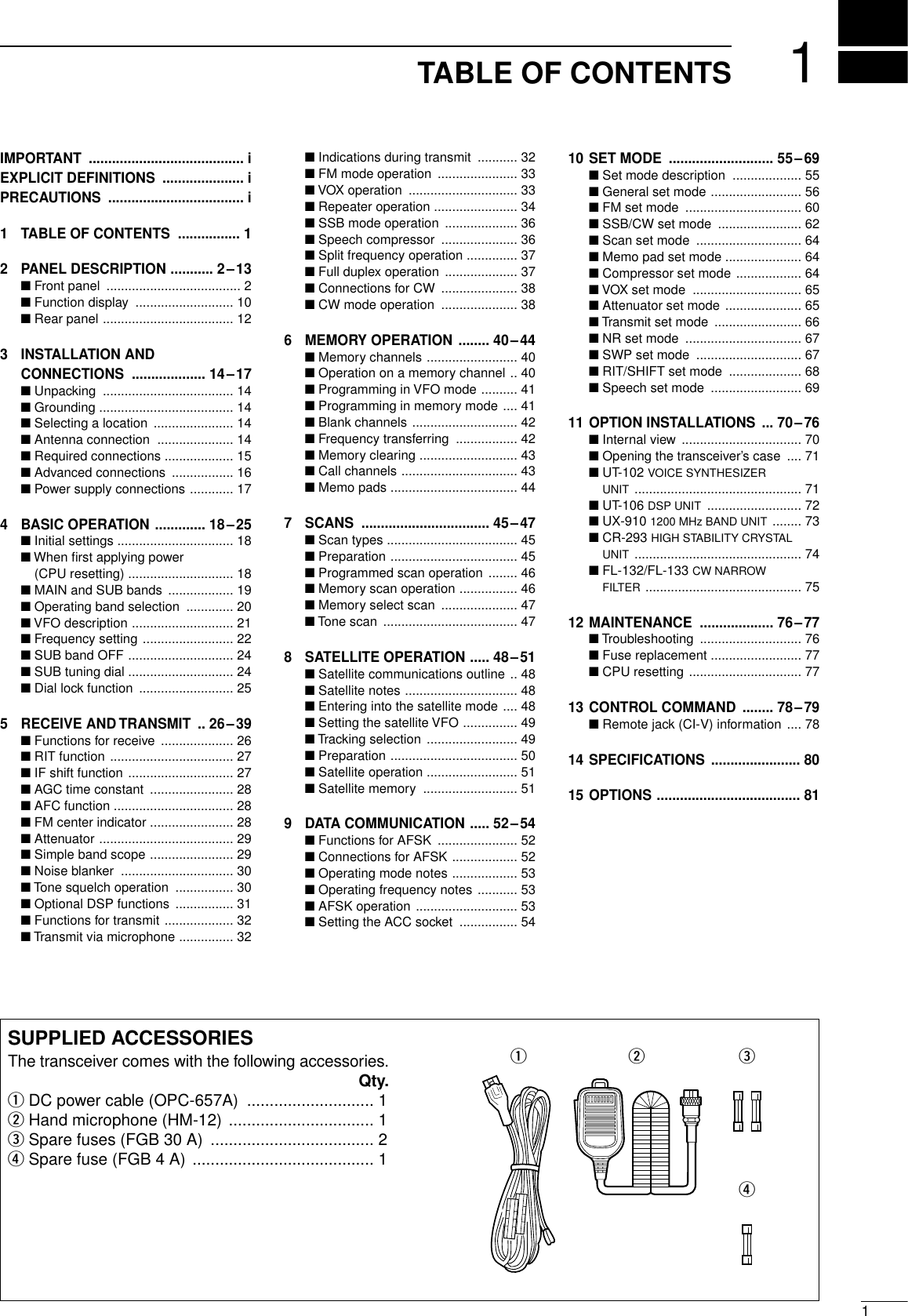
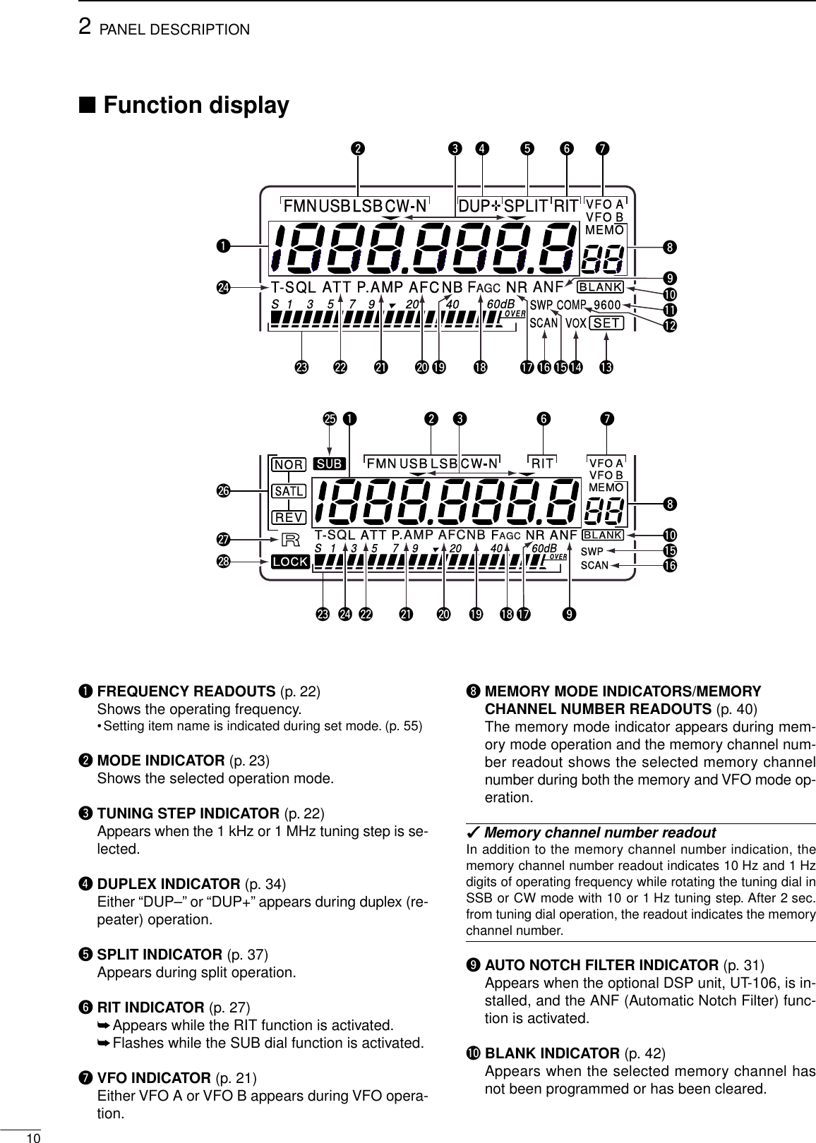
![IMPORTANTREAD THIS INSTRUCTION MANUALCAREFULLY before attempting to operate thetransceiver.SAVE THIS INSTRUCTION MANUAL. Thismanual contains important safety and operating in-structions for the IC-910H.EXPLICIT DEFINITIONSiRWARNING HIGH VOLTAGE! NEVER attachan antenna or internal antenna connector during trans-mission. This may result in an electrical shock or burn.RNEVER apply AC to the [DC13.8V] jack on thetransceiver rear panel. This could cause a fire or ruinthe transceiver.RNEVER apply more than 16 V DC, such as a 24 Vbattery, to the [DC13.8V] jack on the transceiver rearpanel. This could cause a fire or ruin the transceiver.RNEVER let metal, wire or other objects touch anyinternal part or connectors on the rear panel of thetransceiver. This may result in an electric shock.RNEVER expose the transceiver to rain, snow orany liquids.AVOID using or placing the transceiver in areas withtemperatures below –10°C (+14°F) or above +60°C(+140°F). Be aware that temperatures on a vehicle’sdashboard can exceed 80°C (+176°F), resulting in per-manent damage to the transceiver if left there for ex-tended periods.AVOID placing the transceiver in excessively dusty en-vironments or in direct sunlight.AVOID placing the transceiver against walls or puttinganything on top of the transceiver. This will obstructheat dissipation.Place unit in a secure place to avoid inadvertent useby children.During mobile operation, DO NOT operate the trans-ceiver without running the vehicle’s engine. When thetransceiver power is ON and your vehicle’s engine isOFF, the vehicle’s battery will soon become exhausted.Make sure the transceiver power is OFF before start-ing the vehicle. This will avoid possible damage to thetransceiver by ignition voltage spikes.During maritime mobile operation, keep the transceiverand microphone as far away as possible from the mag-netic navigation compass to prevent erroneous indica-tions.BE CAREFUL! The heatsink will become hot whenoperating the transceiver continuously for long periods.BE CAREFUL! If a linear amplifier is connected, setthe transceiver’s RF output power to less than the lin-ear amplifier’s maximum input level, otherwise, the lin-ear amplifier will be damaged.Use Icom microphones only (supplied or optional).Other manufacturer’s microphones have different pinassignments, and connection to the IC-910H maydamage the transceiver.PRECAUTIONSVersions of the IC-910H which display the “CE”symbol on the serial number seal, comply with theEuropean harmonised standard ETS300 684(EMC product standard for Commercially AvailableAmateur Radio Equipment).WORDR WARNINGCAUTIONNOTEDEFINITIONPersonal injury, fire hazard or electric shock may occur.If disregarded, inconvenience only. No risk of personal injury, fire or electric shock.Equipment damage may occur.](https://usermanual.wiki/ICOM-orporated/IC-910H/User-Guide-130522-Page-2.png)
![■Front panelqPOWER SWITCH [POWER]➥Push momentarily to turn power ON.➥Push for 2 sec. to turn power OFF.wTRANSMIT SWITCH [TRANSMIT]Push to select transmitting or receiving.eCOMPRESSION SWITCH [COMP] (p. 36)Push to switch the speech compressor function ONand OFF.•The speech compressor increases average RF outputpower, improving signal strength and readability in SSB.rVOX SWITCH [VOX] (p. 33)Push to switch the VOX function ON and OFF.•The VOX (Voice-Operated Transmission) function tog-gles between transmit and receive with your voice. Thisfunction provides an opportunity to input log entries intoyour computer, etc., while operating.tHEADPHONE JACK [PHONES]Accepts headphones.•Output power: 5 mW with 8–16 Ωload.•When headphones are connected, the internal speakeror connected external speaker does not function.•The MAIN and SUB band audio can be mixed or sepa-rated when using stereo headphones according to setmode settings. (p. 57)yMICROPHONE CONNECTOR [MIC]Accepts the supplied or optional microphone.•See p. 81 for appropriate microphones.•See p. 15 for microphone connector information.uMIC GAIN CONTROL [MIC GAIN]Adjusts microphone input gain.✔How to set the microphone gain.Set the [MIC] control so that the [MAIN]/[SUB] indicator (ALCindicator) some times lights brighter during normal voicetransmission in SSB mode.iRF POWER CONTROL [RF PWR]Continuously varies the RF output power from min-imum to maximum.144 MHz band 5–100 W430(440) MHz band 5–75 W1200 MHz band 1–10 W (optional UX-910)RF PWRIncreasesDecreasesMIC GAINRecommended level for an Icom microphoneIncreasesDecreases22PANEL DESCRIPTIONqo!0 !1 !2 !3wertyui](https://usermanual.wiki/ICOM-orporated/IC-910H/User-Guide-130522-Page-4.png)
![oMAIN BAND INDICATOR [MAIN]➥Lights green while the squelch is opened or a sig-nal is received on the MAIN band; lights red whiletransmitting on the MAIN band.•While transmitting, the indicator also shows ALC con-dition. Brightness increases more than usual whenthe ALC function is activated.➥Flashes when an off-frequency signal is receivedand the FM center detector is activated. (p. 28)!0 RF GAIN CONTROL/SQUELCH CONTROL[RF/SQL] (outer control)Adjusts the RF gain and squelch threshold level forthe MAIN band. The squelch removes noise outputfrom the speaker (closed condition) when no signalis received.•The squelch is particularly effective for FM. It is alsoavailable for other modes.•12 to 13 o’clock position is recommended for any settingof the [RF/SQL] control.•The squelch threshold position for SSB/CW mode canbe set from 12 or 13 o’clock position in SSB/CW setmode. (p. 62)•The control can be set as ‘Auto’(RF gain control in SSBand CW; squelch control in FM) or squelch control (RFgain is fixed at maximum) in set mode as follows. (p. 56)•When setting as RF gain/squelch control•When functioning as RF gain control(Squelch is fixed open; SSB, CW only)•When functioning as squelch control(RF gain is fixed at maximum.)!1 AF CONTROL [AF] (inner control)Varies the audio output level from the speaker forthe MAIN band.!2 SUB BAND INDICATOR [SUB]Lights green while the squelch is opened or a signalis received on the SUB band; lights red while trans-mitting in satellite operation.!3 RF GAIN CONTROL/SQUELCH CONTROL[RF/SQL] (outer control)Adjusts the RF gain and squelch threshold level forthe SUB band. The squelch removes noise outputfrom the speaker (closed condition) when no signalis received.AF RF/SQLNo audio output Max. audio outputDecreases IncreasesSquelch is open.S-meter squelchS-meter squelchthresholdNoise squelch threshold Shallow DeepNoise squelchMinimum RF gainAdjustablerangeMaximum RF gainRecommended levelRF gain adjustablerange (SSB, CW modes)Maximum RF gainS-meter squelchNoise squelch (FM mode)Squelch is open.MODESSB, CWFMAUTORF GAINSQLSQLSET MODE SETTINGSQLSQLRF GAIN + SQLRF GAIN + SQLSQL32PANEL DESCRIPTION](https://usermanual.wiki/ICOM-orporated/IC-910H/User-Guide-130522-Page-5.png)
![42PANEL DESCRIPTION■Front panel (continued)!4 AF CONTROL [AF] (inner control)Varies the audio output level from the speaker forthe SUB band.!5 SET•MENU SWITCH [SET•MENU] (p. 55)➥Push this switch then one of [FM],[SSB/CW], [RIT], [SCAN], [NR], [TRANS-MIT], [COMP], [VOX], [ATT], [SWP],[MPW] or [SPCH] to enter the indepen-dent item set mode.➥Push for 1 sec. to enter the set mode forcommonly used item settings.!6 ATTENUATOR•PRE-AMP SWITCH [ATT•P.AMP]➥Push to switch the attenuator functionON and OFF. (p. 29) Use this function toprotect from signal distortion from exces-sively strong signals.•The attenuation level is independently ad-justable for 144 MHz or 430(440) MHz bandin the ATT set mode.The optional 1200 MHzband attenuation level is fixed and is approx.20 dB. (p. 65)➥Push for 1 sec. to switch the connectedpre-amplifier ON and OFF, when an op-tional pre-amplifier unit, AG-25, AG-35and/or AG-1200, is connected. (p. 16)DO NOT connect any equipment, such as an SWRor power meter between the transceiver and pream-plifier. In such case, the preamplifier may not acti-vate properly.!7 AUTO FREQUENCY CONTROL/NOISEBLANKER•NOISE REDUCTION SWITCH[AFC/NB•NR]➥During FM/FM narrow mode operation,push to switch the AFC (Automatic Fre-quency Control) function ON and OFF.(p. 28)•Automatically tunes the operating frequency,when an off-frequency signal is received, in100 kHz steps. This function also follows thesignal even if the frequency is shifted.➥During SSB or CW mode operation, pushto switch the noise blanker function ONand OFF. (p. 30)•Reduces pulse-type noise, such as ignitionnoise from a vehicle.➥Push for 1 sec. to switch the noise reduc-tion function ON and OFF when an op-tional DSP unit, UT-106, is installed.(p. 31)•Reduces unwanted noise and pulls out thedesired signal only for clear readability.For 1 sec.For 1 sec.For 1 sec.!4 !5 !6 !7 !8 !9 @0 @1 @2 @3](https://usermanual.wiki/ICOM-orporated/IC-910H/User-Guide-130522-Page-6.png)
![52PANEL DESCRIPTION!8 AUTO GAIN CONTROL•AUTO NOTCH FILTERSWITCH [AGC•ANF]➥Push to switch the time constant of theautomatic gain control to SLOW andFAST for the MAIN band.* (p. 28)•SLOW selection (“FAGC”disappears) duringSSB (USB or LSB) operation, FAST selection(“FAGC”appears) during CW, data operationand while tuning with fast tuning dial rotationare recommended.*The AGC time constant can be selected on theMAIN band only. FAST selection is fixed on theSUB band.➥Push for 1 sec. to switch the automaticnotch filter function ON and OFF whenthe optional DSP unit, UT-106, is in-stalled. (p. 31)•Reduces interference signals such as beat,RTTY or CW signals and the notch frequencyautomatically follows the interfering signal.!9 kHz/MHz•TUNING STEP SELECTION SWITCH[kHz/MHz] (p. 22)➥Push to select tuning step for the tuningdial or scanning from 1 kHz, 1 MHz stepand regular tuning step* in sequence •“ZZ”appears above the 1 kHz or 1 MHz digitwhen 1 kHz or 1 MHz tuning step is selected,respectively.*The regular tuning step is selected for eachoperating mode as follows.➥Push for 1 sec. to enter the regular tun-ing step selection mode.•The tuning step can be selected for each op-erating mode independently.•SSB/CW mode: 1, 10, 50 and 100 Hz step;FM mode: 0.1, 5, 6.25, 10, 12.5, 20, 25 and100 kHz step can be selected by rotating thetuning dial.@0 SPEECH•LOCK SWITCH [SPCH•LOCK]➥Announces the receiving signal strengthand/or selected readout frequency whenthe optional UT-102 is installed. (pgs. 69,71)➥Push for 1 sec. to switch the tuning diallock function ON and OFF to prevent ac-cidental setting changes. (p. 25)@1 TUNING DIALChanges the displayed frequency, selects set modeitems, etc.@2 BRAKE ADJUSTMENT SCREW Adjust the tension of the tuning dial.•Rotate clockwise to increase the tension; counterclock-wise to decrease the tension.@3 MEMORY CHANNEL UP/DOWN SWITCHES[YYUP]/[DOWN ZZ](p. 40)➥Push [YUP] to change the memorychannel up; push [DOWN Z] to changethe memory channel down.•Memory channel changes continuously whileholding either switch.•Memory channels can be selected both inVFO and memory modes.For 1 sec.ororBrake adjustment screwFor 1 sec.For 1 sec.For 1 sec.](https://usermanual.wiki/ICOM-orporated/IC-910H/User-Guide-130522-Page-7.png)
![62PANEL DESCRIPTION@4 RIT CONTROL [RIT] (p. 27)Shifts the receive frequency without changing thetransmit frequency for the MAIN band only while theRIT function is activated.•SSB/CW mode : ±1.0 kHz* in 10 Hz step•FM mode : ±5.0 kHz* in 50 Hz step*For 1200 MHz band; ±2.0 kHz and ±10.0 kHz, respec-tively when the optional UX-910 is installed.•By using the Sub dial function, the RIT control can beused as the MAIN/SUB tuning dial or the SUB band IFshift control. See page 24 for details.@5 IF SHIFT CONTROL [SHIFT]Shifts the center frequency of the receiver’s IF pass-band within 1.2 kHz range.•By using the Sub dial function, the IF shift control can beused as the MAIN/SUB tuning dial or the SUB band IFshift control. See page 24 for details.✔What is the Sub dial function?The [RIT] and [SHIFT] controls are used for RIT and IF shiftcontrols for the MAIN band by default. However, the Sub dialfunction assigns these controls as the MAIN/SUB tuning dialor the SUB band IF shift control. (p. 24, 68)@6 SATELLITE SWITCH [SATELLITE]➥Push to enter satellite mode (RX onMAIN, TX on SUB band). Push again toreturn to the condition before enteringinto the satellite mode.➥Push to enter satellite mode using thecurrent operating frequencies whenpushing for 1 sec.•To change the normal and reverse satelliteoperations, push [F-INP/ENT] for 1 sec.@7 RIT SWITCH [RIT] (p. 27)➥Push to switch the RIT control activity ONand OFF.•“RIT”indicator appears when the RIT func-tion is in use.➥Push for 1 sec. to switch the Sub dialfunction ON and OFF.•“RIT”indicator flashes and the [RIT] and[SHIFT] controllers acts as the controllersspecified in the RIT/SHIFT set mode. (p. 68)@8 KEYPADNumeral and other function keys for tuning and ac-tivating functions.See the table at right.For 1 sec.For 1 sec.For 1 sec.RIT SHIFT RIT SHIFT RIT SHIFTCenter positionMax. counter-clockwise position Max. clockwise position■Front panel (continued)@4@5@6@8@7](https://usermanual.wiki/ICOM-orporated/IC-910H/User-Guide-130522-Page-8.png)
![82PANEL DESCRIPTION@9 SPLIT•DUPLEX SWITCH [SPLIT•DUP]➥Push to turn the split function, with theVFO A and B, ON and OFF. (p. 37)•The split operation is not available for theSUB band.➥Push for 1 sec. to select the duplex (re-peater) direction or to turn the functionOFF. (p. 34)•The duplex operation is not available for theSUB band.#0 SSB/CW•CW-NARROW SWITCH [SSB/CW•CW-N]➥Push to switch the operating mode be-tween SSB and CW. (p. 23)➥Push for 1 sec. to switch the operatingmode between USB and LSB or betweenCW and CW narrow during SSB or CWmode, respectively.#1 FM•FM-NARROW SWITCH [FM•FM-N] (p. 23)➥Push to switch the operating mode be-tween FM and FM repeater mode.•The duplex operation can be made in MAINband only, it cannot be operated in SUBband.➥Push for 1 sec. to switch the operatingmode between FM and FM-N (FM nar-row).•The FM-N mode cannot be selected in1200 MHz band operation.#2 TONE SWITCH [TONE]➥Push to turn the tone encoder functionON and OFF in FM mode. (p. 31; exceptfor European version)•“T”indicator appears in the display when thetone encoder is activated.➥Push to transmit a 1750 Hz repeater tonein FM mode for European version.Available repeater tones (Unit: Hz)#3 MAIN/SUB CHANGE•BAND SWITCH[M/S•BAND]➥Push to replace the MAIN band’s fre-quency and mode with the SUB band’s.(p. 19)➥Push for 1 sec. to change the operatingband during single band operation orwhen the optional band unit, UX-910, isinstalled. (p. 20)For 1 sec.For 1 sec.For 1 sec.For 1 sec.#5 #4 #3 #2 #1 #0 @967.069.371.974.477.079.782.5085.4088.5091.5094.8097.4100.0103.5107.2110.9114.8118.8123.0127.3131.8136.5141.3146.2151.4156.7159.8162.2165.5167.9171.3173.8177.3179.9183.5186.2189.9192.8196.6199.5203.5206.5210.7218.1225.7229.1233.6241.8250.3254.1■Front panel (continued)](https://usermanual.wiki/ICOM-orporated/IC-910H/User-Guide-130522-Page-10.png)
![92PANEL DESCRIPTION#4 SUB•SUB OFF SWITCH [SUB•SUB OFF]➥Push to enable the SUB band controlfrom the tuning dial, keypad, etc. (p. 19)•“SUB”indicator appears.➥Push for 1 sec. to turn the SUB bandreadout indication ON and OFF. (p. 24)#5 CALL•TONE SQUELCH SWITCH [CALL•T-SQL]➥Push to select the call channel of the op-erating band.The call channel can be se-lected from both the VFO and memorymode operation. (p. 43)➥Push for 1 sec. to turn the tone squelchfunction ON and OFF during FM modeoperation. (p. 30)•“T-SQL”indicator appears when the tonesquelch is activated.For 1 sec.For 1 sec.](https://usermanual.wiki/ICOM-orporated/IC-910H/User-Guide-130522-Page-11.png)
![112PANEL DESCRIPTION!1 DATA TRANSMISSION SPEED INDICATOR(p. 52)Appears when 9600 bps speed is selected forpacket transmission.!2 SPEECH COMPRESSOR INDICATOR (p. 36)Appears when the speech compressor is activated.!3 SET INDICATOR (p. 55)Appears when [SET] is pushed.Disappears after any switch is pushed.!4 VOX INDICATOR (p. 33)Appears when the VOX function is activated.!5 SWEEP INDICATOR (p. 29)Flashes while the simple bandscope function is ac-tivated.!6 SCAN INDICATOR (p. 46)Flashes while scanning.!7 NOISE REDUCTION INDICATOR (p. 31)Appears when the optional DSP unit, UT-106, is in-stalled and the noise reduction is activated.!8 AGC TIME CONSTANT INDICATOR (p. 28)Appears when the FAST AGC time constant is se-lected; disappears when the SLOW AGC time con-stant is selected.!9 NOISE BLANKER INDICATOR (p. 30)Appears when the noise blanker function is acti-vated.@0 AUTO FREQUENCY CONTROL INDICATOR(p. 28)Appears when the AFC (Automatic Frequency Con-trol) function is activated.@1 PRE-AMP INDICATOR (p. 16)Appears when the optional pre-amplifier unit,AG-25, AG-35 and/or AG-1200, is connected andthe pre-amplifier function is activated.@2 ATTENUATOR INDICATOR (p. 29)Appears when the attenuator is activated.@3 MULTI-FUNCTION BAR METER➥Shows the receiving signal strength as an S-meter while receiving. Peak hold function is avail-able and can be switched ON and OFF in regularset mode. (pgs. 26, 56)➥Shows the relative transmit output power level asan RF power indicator during transmit. (p. 32)➥Shows signal availability in the sweeping band,and the “▼”indicator indicates the center of thesweeping frequency band.@4 TONE SQUELCH INDICATOR (pgs. 30, 34)“T”appears when the tone encoder function is acti-vated; “T-SQL”appears when the tone squelch func-tion is activated.@5 SUB INDICATOR (p. 19)Appears when the SUB band access is enabled.@6 SATELLITE INDICATOR (p. 49)Appears while satellite operation mode is selected.•- : Satellite operation with normal modeis selected.•- : Satellite operation with reverse modeis selected.@7 REMOTE INDICATOR (p. 78)Appears when the transceiver is controlled remotelyvia the optional CI-V level converter, CT-17.@8 LOCK INDICATOR (p. 25)Appears when the dial lock function is activated.REVSATLNORSATL](https://usermanual.wiki/ICOM-orporated/IC-910H/User-Guide-130522-Page-13.png)
![122PANEL DESCRIPTION■Rear panelq430(440) MHz ANTENNA CONNECTOR (p. 15)Accepts a 50 Ωantenna with a type-N connector.wDC POWER SOCKET [DC 13.8V] (p. 17)Accepts 13.8 V DC through the supplied DC powercable (OPC-657A).e144 MHz ANTENNA CONNECTOR (p. 15)Accept a 50 Ωantenna with a PL-259 connector.rSUB BAND EXTERNAL SPEAKER JACK [SP (SUB)]tMAIN BAND EXTERNAL SPEAKER JACK [SP (MAIN)] (p. 16)Accepts a 4–8 Ωspeaker.By connecting an external speaker for each or bothjacks, the audio for both the MAIN and SUB bandsis output as follows.y1200 MHz ANTENNA CONNECTOR (p. 15)Available when the optional 1200 MHz band unit isinstalled. Accepts a 50 Ωantenna with a type-Nconnector.uKEY JACK [KEY] (p. 15)Accepts a paddle, a straight key or external elec-tronic keyer with 1⁄8inch standard plug.iSUB BAND DATA SOCKET [DATA (SUB)]oMAIN BAND DATA SOCKET [DATA (MAIN)](p. 13)6-pin mini plug DIN jack to connect a TNC, etc. forhigh speed data communications.Simultaneous data communications are provided byequipping independent data sockets for both MAINand SUB bands.!0 ACCESSORY SOCKET [ACC(1)]Enables connection of external equipment such asa TNC for data communications, etc.•See the right table for socket information.!1 CI-V REMOTE CONTROL JACK [REMOTE](p. 78)Designed for use with a personal computer via theoptional CT-17 for remote control of transceiverfunctions.!2 GROUND TERMINAL [GND] (p 14)Connect this terminal to a ground to prevent electri-cal shocks and other problems.(dot)(com)(dash)(+)(_)Rear panelview +_o!2wertyuiq!0!1MAIN AF SUB AFNo Int. SP Int. SPSP (MAIN) Ext. SP Ext. SPSP (SUB) Int. SP Ext. SPBoth Ext. SP (MAIN) Ext. SP (SUB)](https://usermanual.wiki/ICOM-orporated/IC-910H/User-Guide-130522-Page-14.png)
![DATA Socket Pin No. Pin Name DescriptionACC(1) Socket Pin No. Pin Name Description Specification132PANEL DESCRIPTIONDACC SOCKETSDDATA SOCKETS12345678NCGNDSENDMODAFSQLS13.8 VALCNo connection.Connect to ground.Input terminal to transmit the trans-ceiver in relation to the external equip-ment. (Grounded: transmits)Input terminal for the modulation cir-cuit.Output terminal for AF signals fromthe AF detector circuit. Output level isfixed, regardless of [AF] control.Output terminal for squelch condition(Open/Close). Outputs grounded levelsignal when squelch is opened.Output terminal for 13.8 V DC, in rela-tion to the [POWER].Input terminal for ALC control.Transmit voltage : –0.5 to +0.8 VOutput current : Less than 20 mAInput current (Tx) : Less than 200 mAOutput impedance : 10 kΩInput level : 100 mV rmsOutput impedance : 4.7 kΩOutput level : 100–300 mV rmsSquelch open : Less than 0.3 V/5 mASquelch close : More than 6.0 V/100 µAOutput current : Less than 1 AInput impedance : More than 10 kΩControl voltage : –4 to 0 V12345678123456DATA INGNDPTTPDATAOUTAF OUTSQLInput terminal for data (common for both 1200 and 9600 bps) Ground line for the DATA IN, DATA OUT and AF OUT.Transmits when this terminal is grounded.Received data output terminal for 9600 bps operation.Received data output terminal for 1200 bps operation.Output terminal for squelch condition (Open/Close). Outputs grounded level signalwhen squelch is opened, +8 V level signal when squelch is closed.qweytr](https://usermanual.wiki/ICOM-orporated/IC-910H/User-Guide-130522-Page-15.png)
![314INSTALLATION AND CONNECTIONS■UnpackingAfter unpacking, immediately report any damage to thedelivering carrier or dealer. Keep the shipping cartons.For a description and a diagram of accessory equip-ment included with the IC-910H, see ‘Supplied acces-sories’on p. 1 of this manual.■GroundingTo prevent electrical shock, television interference(TVI), broadcast interference (BCI) and other prob-lems, ground the transceiver through the GROUNDterminal on the rear panel.For best results, connect a heavy gauge wire or strapto a long earth-sunk copper rod. Make the distance be-tween the [GND] terminal and ground as short as pos-sible.RWARNING: NEVER connect the [GND]terminal to a gas or electric pipe, since the connec-tion could cause an explosion or electric shock.■Selecting a locationSelect a location for the transceiver that allows ade-quate air circulation, free from extreme heat, cold, orvibrations, and away from TV sets, TV antenna ele-ments, radios and other electro-magnetic sources.The base of the trans-ceiver has an ad-justable stand for desk-top use. Set the standto depending on youroperating conditions.■Antenna connectionFor radio communications, the antenna is of critical im-portance, along with output power and sensitivity. Se-lect antenna(s), such as a well-matched 50 Ωantenna,and feedline. 1.5:1 or better of Voltage Standing WaveRatio (VSWR) is recommended for your desired band.Of course, the transmission line should be a coaxialcable.CAUTION: Protect your transceiver from lightningby using a lightning arrestor.PL-259 CONNECTOR INSTALLATION EXAMPLE TYPE-N CONNECTOR INSTALLATION EXAMPLE30 mm ≈9⁄8in 10 mm ≈3⁄8in 1–2 mm ≈1⁄16 inSlide the coupling ring down. Strip the cable jacket and soft solder.Slide the connector body on and solder it.Screw the coupling ring onto the connector body.Strip the cable as shown at left. Soft solder the center conductor.qwerSlide the nut, rubber gasket and clamp over the coaxial cable, then cut the end of the cable evenly.Strip the cable and fold the braid back over the clamp.Soft solder the center conductor. Install the center conductor pin and solder it.Carefully slide the plug body into place aligning the center conductor pin on the cable. Tighten the nut onto the plug body.qwer15 mm3 mm 6 mm30 mm10 mm (soft solder)10 mm1–2 mmsolder solderSoftsolderCoupling ringNo spaceSolder holeBe sure the center conductor is the same height as the plug body.Clamp CenterconductorWasherNut Rubber gasket](https://usermanual.wiki/ICOM-orporated/IC-910H/User-Guide-130522-Page-16.png)
![DC POWER SUPPLY (p. 17)[430(440)MHz ANT] (p. 14)[1200MHz ANT] (p. 14)[144MHz ANT] (p. 14)[KEY] jack (p. 38)GROUND (p. 14)Required for optional UX-910 operation.+_13.8 V DC More than 25 A(dot)(com)(dash)+_153INSTALLATION AND CONNECTIONSSM-20 DESKTOP MICROPHONE (optional) MICROPHONE CONNECTOR (Front panel view)Input impedance: 8–16 ΩAudio output power: 5 mW with 8 Ω loadOutput power may differaccording to the headphoneHM-12 HAND MICROPHONEHEADPHONESq MIC (Microphone input)w +8V (Max. 8 V DC 10 mA)e MIC U/D (Frequency up/down)r SQL S (Squelch switch)t PTTy GND (PTT ground)u GND (Microphone ground)i AF OUT (varies with [AF])CAUTION: DO NOT short pin 2 to ground as this can damage the internal 8 V regulator. DC voltage is applied to pin 1 for microphone operation. Take care when using a non-Icom microphone.qwertyui■Required connections•Front panel•Rear panel](https://usermanual.wiki/ICOM-orporated/IC-910H/User-Guide-130522-Page-17.png)
![163INSTALLATION AND CONNECTIONSMB-23 CARRYING HANDLEPREAMP (p. 59)(144 MHz/430(440) MHz/1200 MHz) EXTERNAL SPEAKER(MAIN/SUB) (p. 12)CT-17144 MHz : AG-25430(440) MHz : AG-351200 MHz : AG-1200External all-weather, mast mounting preamplifiers are available.MAINMAIN144 MHz430(440) MHz 1200 MHz (optional)SUBSUBsp-7icomUse 4–8 Ω speakers.[REMOTE] (p. 78)Used for computer control and transceive operation.Used for external equipment control.ACC SOCKETS (pgs. 13, 52) DATA SOCKETS (MAIN/SUB) (pgs. 13, 52)CAUTION: NEVER connect equipment (i.e. power, SWR meter) between transceiver and preamplifier.■Advanced connections•Front panel•Rear panel](https://usermanual.wiki/ICOM-orporated/IC-910H/User-Guide-130522-Page-18.png)
![AC outletAC cable13.8 V DC 25 AA DC power supplyBlack_Red+IC-910HSupplied DC power cable173INSTALLATION AND CONNECTIONS24V CigaIC-910H12 Vbattery SuppliedDC power cable+ red_ blackCrimpSolderGrommetCONNECTING A VEHICLE BATTERYCONNECTING A DC POWER SUPPLY■Power supply connectionsUse an optional DC power supply with a 25 A capacityand above when operating the transceiver with ACpower. Refer to the diagrams below.CAUTION: Before connecting the DC powercable, check the following important items. Makesure:•The [POWER] switch is OFF.•Output voltage of the power source is 12–15 Vwhen you use a non-Icom power supply.•DC power cable polarity is correct.Red : positive +terminalBlack : negative _terminalNEVER connect toa 24 V battery.NEVER use the cig-arette lighter socket asa power source.NOTE: Use terminals forthe cable connections.](https://usermanual.wiki/ICOM-orporated/IC-910H/User-Guide-130522-Page-19.png)
![■Initial settingsAfter resetting the transceiver, set controls andswitches as shown in the figure below.Turn power ON, then check the display. If any of the fol-lowing indicators appear, turn them OFF as follows:•Quick tuning step indicator “▼”: Push [kHz/MHz].•RIT indicator “RIT”: Push [RIT].•Split indicator “SPLIT”: Push [SPLIT].CCW : Max. counterclockwise418BASIC OPERATION■When first applying power (CPU resetting)Before first applying power, make sure all connectionsrequired for your system are complete by referring toChapter 3. Then, reset the transceiver using the fol-lowing procedure.qMake sure the transceiver power is OFF.wWhile pushing [MW 4] and [M-CL 5], push[POWER] to turn power ON.•The internal CPU is reset.•The transceiver displays its initial VFO frequencies whenresetting is complete.Resetting CLEARS all programmed contents inmemory channels and returns programmed valuesin set mode to default values.[POWER] [MW 4] [M-CL 5]FMVFO AVFVFOAFMS135792020 4040 60dB60dB60dBS13 5 7920 40[TRANSMIT]: OFF[COMP]: OFF[VOX]: OFF[AF] (SUB band):CCW[RF/SQL]: (SUB band)12 o’clock[MIC]: CCW [SET]: OFF[ATT(P.AMP)]: OFF[RF PWR]: CCW[AFC/NB]: OFF[AGC]: OFF[RIT]: 12 o’clock[SHIFT]: 12 o’clock[RIT]: OFF[POWER]: OFF[AF] (MAIN band): CCW [RF/SQL] (MAIN band):12 o’clock [SATELLITE]: OFF](https://usermanual.wiki/ICOM-orporated/IC-910H/User-Guide-130522-Page-20.png)
![194BASIC OPERATION■MAIN and SUB bandsThe IC-910H has dual bands: 144 MHz and 430(440)MHz. These bands can be assigned to the MAIN andSUB bands for operating convenience.Each MAIN and SUB bands have independent fea-tures.The MAIN band is the operation for both transmit andreceive, and is displayed in the upper area of the func-tion display.The SUB band is the operation for only re-ceive, and is displayed in the lower area of the functiondisplay.Simultaneous receive on both the MAIN and SUBbands is possible, however the transmission canonly be transmitted on the MAIN band— not on theSUB band.In the case of satellite operation mode, the SUBband is used for the transmission band.◊Exchanging the MAIN and SUB bandsThe function display shows both the MAIN and SUBband frequencies and both bands can receive signalssimultaneously.Assign 144 MHz or 430(440) MHz band, whicheverband you want to transmit or be called on, as the MAINband.➥Push [M/S] to exchange the MAIN and SUB bands.FMVFO AVFVFOAFMS1357920 40 60dB60dB60dBS13 5 7920 40MAIN band displaySUB band displayFMVFO AVFVFOAFMS 1 3 5792020 4040 60dB60dB60dBS13 5 7920 40FMVFO AVFVFOAFMS 1 3 5792020 4040 60dB60dB60dBS13 5 7920 40MAIN band displaySUB band displayFMVFO AVFVFOAFMS 1 3 5792020 4040 60dB60dB60dBS13 5 7920 40FMVFO AVFVFOAFMS 1 3 5792020 4040 60dB60dB60dBS13 5 7920 40SUB◊Accessing the SUB band Normally, any operations, such as tuning, operatingmode selection, memory channel selection and pro-gramming, etc., are performed on the MAIN band.However, these operations can be performed on theSUB band by using the SUB band access capability.➥Push [SUB] to switch the SUB band access capa-bility ON and OFF.•“SUB”indicator appears while the SUB band access ca-pability is activated.•Even during SUB band access, transmission cannot bemade on the SUB band.](https://usermanual.wiki/ICOM-orporated/IC-910H/User-Guide-130522-Page-21.png)
![204BASIC OPERATION■Operating band selection (optional UX-910 is required)The IC-910H can be used on the additional 1200 MHzband with the optional UX-910. The operating bandcan be selected by pushing [M/S•BAND] for 1 sec.◊Selecting on the MAIN bandqPush [SUB] to cancel the SUB band access, if re-quired.wPush [M/S•BAND] for 1 sec. to select operatingband.NOTE: The same operating band cannot be as-signed on both MAIN and SUB bands, simultane-ously.◊Selecting on the SUB bandqPush [SUB] to enable the SUB band access.•“SUB”indicator appears.wPush [M/S•BAND] for 1 sec. to select operatingband.[SUB] [M/S•BAND]FMVFO AVFVFOAS 1 3 5792020 4040 60dB60dB60dBS13 5 7920 40Select 1200 MHz to MAIN band.FMVFO AVFVFOAFMSUBS 1 3 5792020 4040 60dB60dB60dBS13 5 7920 40Select 1200 MHz to SUB band.](https://usermanual.wiki/ICOM-orporated/IC-910H/User-Guide-130522-Page-22.png)
![214BASIC OPERATION■VFO descriptionThe IC-910H has two VFOs for both bands, speciallysuited for instant selection of 2 frequencies or split fre-quency operation. The VFOs are called VFO A andVFO B. You can use the desired VFO to call up a fre-quency and operating mode for your operation.VFO is an abbreviation of Variable Frequency Oscilla-tor, and traditionally refers to an oscillator.◊Selecting the VFO A/B➥Push [A/B 3] to switch between the VFO A andVFO B.◊VFO equalization➥Push [A=B 2] for 1 sec. to equalize the undisplayedVFO condition to the displayed VFO.•3 beeps sound when the VFO equalization is completed.Use two VFOs as a quick memoryWhen you find a new station, but you wish to con-tinue searching, the two VFO system can be usedfor quick memory storage.qPush [A=B 2] for 1 sec. to store the displayed fre-quency into the undisplayed VFO.wContinue searching for stations.ePush [A/B 3] to retrieve the stored frequency.rTo continue searching for stations, push [A/B 3]again.CONVENIENTFMVFO AFMVFO BVFO selectionFMVFO AFMVFO Bundisplayed VFOEqualizes the undisplayed VFO conditionto the displayed VFO.displayed VFO](https://usermanual.wiki/ICOM-orporated/IC-910H/User-Guide-130522-Page-23.png)
![224BASIC OPERATION■Frequency settingThe IC-910H has several tuning steps and a[kHz/MHz] switch for convenient frequency tuning.qPush [M/S] to select the desired frequency band asthe MAIN band; or push [SUB] to access the SUBband.wRotate the tuning dial to select the frequency.•The memory channel number changes to the 10 and1 Hz digits when rotating the tuning dial with 1, 10,100 Hz and 6.25 kHz tuning steps.•When you want to check the 10 and 1 Hz digits duringmemory channel number indication, push and hold [A/B](10 and 1 Hz digits are indicated while holding).◊Tuning step selectionTuning steps can be pre-set independently for FM andSSB/CW. The following steps are selectable.•FM : 0.1, 5, 6.25, 10, 12.5, 20, 25 or 100 kHz•SSB/CW : 1, 10, 50 or 100 HzqPush [M/S] to select the desired frequency band asthe MAIN band; or push [SUB] to access the SUBband.wPush [FM] or [SSB/CW] to select the desired oper-ation mode.ePush [kHz/MHz•TS] for 1 sec. to enter the tuningstep set mode.rRotate the tuning dial to select the desired tuningstep.tPush [kHz/MHz•TS] to return to previous display.◊Quick tuning stepThe operating frequency can be changed in 1 kHzsteps or 1 MHz steps for quick tuning.➥Push [kHz/MHz•TS] to switch the quick tuning stepin sequence 1 kHz, 1 MHz and OFF.USBUSBVFO AUSBUSB10 Hz/1 Hz indicationWhile tuning[kHz/MHz•TS] for 1 sec.FMUSBUSB(20 kHz tuning step)(10 Hz tuning step)FM mode tuning step set modeSSB/CW mode tuning step set mode[kHz/MHz•TS]FMVFO A1 kHz tuning step1 MHz tuning step](https://usermanual.wiki/ICOM-orporated/IC-910H/User-Guide-130522-Page-24.png)
![234BASIC OPERATION◊Frequency setting with the keypadThe operating frequency can be directly entered fromthe keypad.qPush [F-INP ENT] to access the keypad frequencyentry.•All digits of frequency indication disappear.wPush numeral keys to enter the desired operatingfrequency.•The entered number is indicated from the 100 Hz digit.ePush [F-INP ENT] to set the frequency.[EXAMPLE]145.3400 MHz[F-INP ENT] [1] [4] [5] [.] [3] [4] [F-INP] 435.0000 MHz[F-INP ENT] [4] [3] [5] [.] [F-INP ENT] 439.1200 MHz[F-INP ENT] [4] [3] [9] [.] [1] [2] [F-INP ENT] 439.1200 MHz to 439.2604 MHz[F-INP ENT] [.] [2] [6] [0] [4] [F-INP ENT]Pushing numeral keys to 100 Hz digit without push-ing [.] also sets the desired operating frequency.keypad◊Operating mode selectionSSB (USB/LSB), CW, CW-N (CW narrow), FM andFM-N (FM narrow) modes are available in theIC-910H. Select the desired operation mode as follows.•Selecting SSB mode➥Push [SSB/CW] to select USB mode.•USB mode is generally used for SSB phone operationon the VHF and UHF bands.•Push [SSB/CW] for 1 sec. after USB mode selection toswitch between USB and LSB mode.•Selecting CW mode➥Push [SSB/CW] to select CW mode.•Push [SSB/CW] for 1 sec. after CW mode selection toswitch between CW and CW narrow mode.The optional CW narrow filter, FL-132 or FL-133, isrequired for the MAIN or SUB bands, respectively.In satellite operation, the optional FL-133 is neces-sary to operate CW narrow mode in the MAIN (re-ceive) band. No audio is output until the optional CWnarrow filter is installed in the CW narrow mode.•Selecting FM mode➥Push [FM] to select FM mode.•Push [FM] after FM mode selection to turn the repeatermode (duplex negative with repeater tone ON) ON andOFF.•Push [FM] for 1 sec. after FM mode selection to switchbetween FM and FM narrow mode.[FM] [SSB/CW]](https://usermanual.wiki/ICOM-orporated/IC-910H/User-Guide-130522-Page-25.png)
![◊When the [RIT] control is assigned asSUB tuning dialqPush [RIT] for 1 sec.•“RIT”indicator flashes when the SUB tuning dial func-tion is activated.wRotate [RIT] control for the desired tuning directionand speed.•Tuning speed can be adjusted in ±5 steps.eSet [RIT] control to the center position to stops tun-ing.•A beep tone sounds when [RIT] control is set to the cen-ter.rPush [RIT] to cancel the SUB tuning dial function.244BASIC OPERATION■SUB band OFFThe SUB band indication can be deactivated to sim-plify operation.➥Push [SUB•SUB OFF] for 1 sec. to turn the SUBband indication ON and OFF.•Push [M/S•BAND] for 1 sec. to change the operatingband. (p. 20)■SUB tuning dial The IC-910H has a large main tuning dial for frequencysetting. In addition, the [RIT] or [SHIFT] controls canbe used as a SUB tuning dial for dual band simultane-ous tuning, etc. The SUB tuning dial changes the op-erating frequency continuously at a variable speed.To use the SUB tuning dial function, assign the func-tion to either the [RIT] or [SHIFT] control using theRIT/SHIFT set mode.The assigned control can be used for its originalfunction, however, both functions cannot be used si-multaneously.FMVFO A60dBS13 5 7920 40SUB band indication OFF.[SUB•SUB OFF] for 1 sec.FMRITRITVFOAVFOAVFOAFMS 1 3 5792020 4040 60dB60dB60dBS13 5 7920 40While [RIT] is flashing, SUB band can be controlled with sub dial function.Advances the frequency andincreases the speed.Reverses the frequency andincreases the speed.SUB dial functionsslightly.](https://usermanual.wiki/ICOM-orporated/IC-910H/User-Guide-130522-Page-26.png)
![254BASIC OPERATION◊SUB tuning dial assignmentqPush [SET] then [RIT] to enter the RIT/SHIFT setmode.wPush [DN ▼] or [▲UP] to select [RIT] or [SHIFT]control to be assigned.•“rit nob”or “SFt nob”appears.eRotate the tuning dial to select the condition as de-scribed below.•Pushing [M-CL 5] for 1 sec. selects the default setting.rPush [SET] to exit from the RIT/SHIFT set mode.[SET] [DN ▼][▲ UP][RIT][RIT][SHIFT]The [RIT] control functions as [RIT] even when the SUB tuning dial function is in use. (default)The [RIT] control can be used for MAIN band tuning.The [RIT] control can be used for SUB band tuning.The [RIT] control can be used for SUB band IF shift control.The [SHIFT] control functions as [SHIFT] even when the SUB tuning dial function is in use. (default)The [SHIFT] control can be used for SUB band IF shift control.The [SHIFT] control can be used for MAIN band tuning.The [SHIFT] control can be used for SUB band tuning.■Dial lock functionThe dial lock function prevents accidental changescaused by the tuning dial (including the SUB tuning dialfunction).➥Push [SPCH•LOCK] for 1 sec. to turn the dial lockfunction ON and OFF.•“LOCK”indicator appears while the dial lock function isactivated.FMVFO AVFVFOAFMLOCKS 1 3 5792020 4040 60dB60dB60dBS13 5 7920 40LOCK indicatior[SPCH•LOCK] for 1 sec.](https://usermanual.wiki/ICOM-orporated/IC-910H/User-Guide-130522-Page-27.png)
![■Functions for receive◊Volume setting➥Rotate [AF] control for the specified operating band(MAIN or SUB) to output a suitable audio level.◊Squelch settingThe squelch removes noise output from the speaker(closed position) when no signal is received. Thesquelch is particularly effective for FM. It is also avail-able for other modes.With the default setting, noise squelch and S-metersquelch in FM, RF gain and S-meter squelch inSSB/CW mode operation are assigned to [RF/SQL]control. The assignment can be changed in the gen-eral set mode. (p. 56)•When operating in FMqRotate [RF/SQL] fully counterclockwise.wRotate [RF/SQL] clockwise to the position wherethe noise just disappears.•MAIN/SUB band indicator also goes OFF.By rotating [RF/SQL] to a deeper position (clockwise),the S-meter will move and the S-meter squelch func-tion will be activated. When the S-meter squelch is ac-tivated, weak signals, weaker than the S-metersquelch set level, are ignored.•When operating in SSB/CWqRotate [RF/SQL] fully counterclockwise.wRotate [RF/SQL] clockwise to the position wherethe maximum RF gain (S-meter bar disappears),MAIN/SUB band indicator goes OFF, and floornoise disappears.•With the default setting, the squelch opens at 12 o’clockposition, however, the squelch threshold level can be setto 13 o’clock (1 o’clock) position in the SSB/CW setmode. (p. 62)•When rotating [RF/SQL] counterclockwise, RF gain de-creases (lower sensitivity) and the S-meter bar appearsto indicate the receivable RF signal level.[RF/SQL] (SUB)[RF/SQL] (MAIN)526RECEIVE AND TRANSMIT[AF] (SUB)[AF] (MAIN)](https://usermanual.wiki/ICOM-orporated/IC-910H/User-Guide-130522-Page-28.png)
![■RIT functionThe RIT (Receive Incremental Tuning) function com-pensates for off-frequencies of the communicating sta-tion without moving the transmit frequency.The RIT function can be used for the MAIN band only.The function affects the MAIN band even when ac-cessing the SUB band.qPush [RIT] to turn the RIT function ON.•“RIT”indicator appears.wRotate [RIT] control to cancel the off-frequencies.•Rotate [RIT] control to the center position, after commu-nication.ePush [RIT] to cancel the RIT function.•“RIT”indicator disappears.◊RIT variable rangeSSB/CW mode : ±1.0 kHz in 10 Hz steps (±2.0 kHz foroptional 1200 MHz band)FM mode : ±5.0 kHz in 50 Hz steps (±10.0 kHzfor optional 1200 MHz band)FMRITRITFM modeRITRITUSBUSBRIT variable range is displayed for 2 sec. and then returns to frequency indication.RIT variable range is displayed for 2 sec. and then returns to frequency indication.SSB mode[RIT] control[RIT] switch275RECEIVE AND TRANSMIT■IF shift functionThe IF shift function electronically changes the pass-band frequency of the IF (Intermediate Frequency) andcuts out higher or lower frequency components of theIF to reject interference. The function shifts the IF fre-quency up to ±1.2 kHz in 100 Hz steps in SSB/CWmode. The IF shift is especially useful in SSB opera-tion and not available in FM mode.The IF shift function can be used for the SUB bandusing the SUB tuning dial function (p. 24)◊MAIN band IF shift operationqSet the [SHIFT] control to its center position whenthere is no interference.wRotate the [SHIFT] control to adjust for minimum in-terference signal level.•The audio tone may change while the IF shift is in use.◊SUB band IF shift operationqAssign the SUB band IF shift function to either [RIT]or [SHIFT] control using the RIT/SHIFT set mode(p. 68).wPush [RIT] for 1 sec. to turn the SUB tuning dialfunction ON.•“RIT”indicator flashes.eRotate [RIT] or [SHIFT] control for a minimum inter-ference signal level.rPush [RIT] to cancel the SUB tuning dial function.•“RIT”indicator disappears.•Set [RIT] or [SHIFT] control to the center position afterthe communication.In satellite operation mode, the SUB tuning dialfunction cannot be activated.Therefore, the [SHIFT]control acts as an IF shift for the receive band (dis-played in the upper area).Center positionMax. counter-clockwise position Max. clockwise position](https://usermanual.wiki/ICOM-orporated/IC-910H/User-Guide-130522-Page-29.png)
![285RECEIVE AND TRANSMIT■AGC time constantThe AGC (Automatic Gain Control) controls receivergain to produce a constant output level even when thereceived signal strength is varied by fading, etc. UseAGC slow for normal phone operation; AGC fast for re-ceiving data and searching for signals.➥Push [AGC] to switch the time constant betweenfast and slow.•“FAGC”indicator appears when AGC fast is selected.•The AGC time constant is fixed in FM mode regardlessof the FAGC indicator.The SUB band’s AGC is automatically selected asslow in SSB and fast in CW. AGC time constant cannotbe changed in FM mode.■AFC functionThe AFC (Automatic Frequency Control) automaticallytunes the operating frequency when receiving an off-frequency signal or receiving signal shifts in FM or FMnarrow mode.➥Push [AFC/NB] to turn the AFC function ON andOFF.•“AFC”indicator appears when the AFC function is acti-vated.When strong nearby signals are available, the AFCfunction may tune to those signals.■FM center indicatorThe MAIN/SUB band indicators indicate the receivedsignal deviation in FM mode. When an off-center sig-nal is received, the indicator flashes.When an off-center signal is received, rotate the tun-ing dial or use the RIT function to illuminate the indica-tor continuously.The FM center indicator can be turned OFF using theFM set mode. (p. 61)[AGC]CWVFO AFAGCAGC[AFC/NB]FMVFO AAFCAFCFlashes in 300 msec. intervals.](https://usermanual.wiki/ICOM-orporated/IC-910H/User-Guide-130522-Page-30.png)
![■AttenuatorThe attenuator prevents desired signals from distortingwhen very strong signals are near the desired fre-quency, or when very strong electric fields, such asfrom broadcasting stations are near from your location.The attenuator can be set to both or either band sepa-rately, and the attenuation level can be set for eachband independently.➥Push [ATT] to turn the attenuator ON and OFF.•“ATT”indicator appears when the attenuator is activated.◊Setting the attenuation levelqPush [M/S•BAND] or [SUB] to select the desiredband of the attenuation level to be set.wPush [SET] then [ATT] to enter the attenuator setmode.eRotate the tuning dial to select attenuation level.•Push [M-CL 5] to return to the default value.rPush [SET] to exit the attenuator set mode.NOTE: When using the noise blanker, receivedaudio may be distorted if they are excessivelystrong.■Simple band scopeThis function allows you to visually “sweep”an areasurrounding the set frequency for other signals. De-tected signals are indicated graphically on the S-meter.qSet the operating frequency and mode.wPush [SWP 0] to turn the simple band scope func-tion ON and OFF.•“SWP”indicator flashes when the simple band scopefunction is activated.•Detected signals are indicated using the S-meter and“▼”indicator, displayed above the S-meter, shows thecenter frequency (displayed frequency).•The signal availability is detected by the noise squelchcondition (open or close).eTo monitor the detected signal, rotate the tuning dialto set the appearing “dot”of the S-meter to belowthe “▼”indicator.•The frequency readout shows the detected signal fre-quency.◊Setting sweeping time intervalqPush [SET] then [SWP 0] to enter the sweep setmode.wRotate the tuning dial to select sweeping time inter-val.•Push [M-CL 5] to return to the default value.ePush [SWP 0] to exit the sweep set mode.295RECEIVE AND TRANSMIT[ATT]CWVFO AATT[SWP 0]FMVFOASWPIndicates detected signals Sweep centerShows ±10 channels around the displayed frequency.Attenuation levels144 MHz/ 0–100% variable430(440) MHz bands Approx. 15 dB attenuationat 100% setting1200 MHz band Approx. 20 dB fixed (optional)](https://usermanual.wiki/ICOM-orporated/IC-910H/User-Guide-130522-Page-31.png)
![305RECEIVE AND TRANSMIT■Noise blanker When operating in SSB or CW mode, pulse-type noisemay be received such as from car ignitions. In thiscase, the noise blanker eliminates such noise.The noise blanker is effective on both the MAIN andSUB bands but cannot be used for FM, or non-pulse-type noise.➥Push [AFC/NB] to turn the noise blanker functionON and OFF.•“NB”indicator appears when the noise blanker is acti-vated.•The noise blanker turns ON or OFF for both bands si-multaneously.When using the noise blanker, received audio maybe distorted if the signals are excessively strong.■Tone squelch operationThe tone squelch opens only when receiving a signalwith the same pre-programmed subaudible tone. Youcan silently wait for a call from group members usingthe same tone.You can check the tone frequency usingthe tone scan function if desired. (p. 47)qSelect the desired band by pushing [M/S•BAND].wPush [FM] to select FM mode, then set the desiredfrequency.ePush [CALL•T-SQL] for 1 sec. to activate the tonesquelch.•“T-SQL”indicator appears.rWhen the signal with correct tone is received, thesquelch opens and audio can be heard.•When a signal with incorrect tone or no tone is received,the squelch does not open, however, the S-meter indi-cates the signal strength.•Push and hold [CHECK 7] to open the squelch manuallyand keep pushing to monitor.tOperate the transceiver in a normal way (push[PTT] to transmit; release [PTT] to receive).yPush [CALL•T-SQL] for 1 sec. to cancel the tonesquelch.•“T-SQL”indicator disappears.◊Setting the tone squelch frequencyThe tone squelch frequencies can be independentlyset for each band.qPush [M/S•BAND] to select the band for the tonesquelch frequency to be set.wPush [SET] then [FM] to enter the FM set mode.ePush [DN ▼] or [▲UP] to select tone squelch fre-quency item.rRotate the tuning dial to select the desired tonesquelch frequency.tPush [FM] to exit from the FM set mode.Tone frequency list unit: HzFMVFO AT-SQL[SET] Tuning dial[FM][CALL•T-SQL][DN √]/[∫ UP]67.069.371.974.477.079.782.5085.4088.5091.5094.8097.4100.0103.5107.2110.9114.8118.8123.0127.3131.8136.5141.3146.2151.4156.7159.8162.2165.5167.9171.3173.8177.3179.9183.5186.2189.9192.8196.6199.5203.5206.5210.7218.1225.7229.1233.6241.8250.3254.1[AFC/NB]CWVFO ANB](https://usermanual.wiki/ICOM-orporated/IC-910H/User-Guide-130522-Page-32.png)
![315RECEIVE AND TRANSMIT■Optional DSP functionsTo activate the following functions, the optional DSPunit, UT-106, must be installed for both or either theMAIN and/or SUB bands.◊NR (Noise Reduction) functionThis function reduces noise components and picks outdesired signals which are buried in noise.The receivedaudio signals are converted to digital signals and thenthe desired signals are separated from the noise. Thenoise reduction function is available for all operatingmodes.qPush [M/S•BAND] or [SUB] to select the band youwish to activate, if required.wPush [AFC/NB•NR] for 1 sec. to turn the noise re-duction function ON and OFF.•“NR”indicator appears while the automatic notch filter isactivated.◊Setting the noise reduction levelqPush [SET] then [AFC/NB•NR] to enter the noisereduction set mode.wRotate the tuning dial to select the desired noise re-duction level.•Push [M-CL 5] for 1 sec. to return to the default value.ePush [AFC/NB•NR] to exit from the noise reductionset mode.USBUSBVFO ANR[AFC/NB•NR] for 1 sec.◊ANF (Automatic Notch Filter) functionThis function automatically attenuates beat tones, tun-ing signals, etc., even if they are moving. The auto-matic notch filter functions in SSB/FM modes.qPush [M/S•BAND] or [SUB] to select the band youwish to activate, if required.wPush [AGC•ANF] for 1 sec. to turn the automaticnotch filter function ON and OFF.•“ANF”indicator appears while the automatic notch filteris activated.USBUSBVFO AANFANF[AGC•ANF] for 1 sec.Unwanted tone frequencyDesired signal (AF) Desired signal (AF)Particular frequencyis attenuatedAuto notch OFF Auto notch ONoptional UT-106](https://usermanual.wiki/ICOM-orporated/IC-910H/User-Guide-130522-Page-33.png)
![325RECEIVE AND TRANSMIT■Functions for transmit◊Output powerThe transmit output power can be continuously ad-justed with [RF PWR].Available power144 MHz band : 5–100 W 430(440) MHz band : 5–75 W 1200 MHz band : 1–10 W (optional)NOTE: To prevent interference, listen on the fre-quency to make sure the frequency is clear beforetransmitting by pushing [CHECK 7].[RF PWR]■Transmission viamicrophoneWhen transmitting with a microphone, push [PTT] andspeak into the microphone at a normal voice level.To maximize the readability of your transmitted sig-nal (voice), pause a few sec. after pushing [PTT]. Donot hold the microphone too close to your mouth.◊Microphone gainRotate [MIC GAIN] clockwise to increase, counter-clockwise to decrease the microphone gain.9–12 o’clock position is recommended for [MIC GAIN].[PTT] switchHM-12■Indications during transmit◊Transmit indicatorThe MAIN band indicator lights red while transmitting.However, the SUB band indicator lights red duringsatellite operation.◊RF power indicatorThe S-meter for the MAIN band is used as the RFpower indicator to indicate the relative output powerlevel. However, the S-meter for the SUB band is usedas the RF power indicator during satellite operation.◊Time-out timerThe time-out timer limits the continuously transmittabletime period, and is selectable from 3, 5, 10, 20, 30 min.and OFF in TRANSMIT set mode. (p. 66)◊PTT lock functionDeactivate [PTT] and [TRANSMIT] switches. The func-tion can be switched ON and OFF in TRANSMIT setmode. (p. 66)S-meter while receivingRF power indicator while transmittingFMVFO AVFVFOAFMS 1 3 5792020 4040 60dB60dB60dBOVERS13 5 7920 40OVEROVER](https://usermanual.wiki/ICOM-orporated/IC-910H/User-Guide-130522-Page-34.png)
![335RECEIVE AND TRANSMIT■FM mode operationqPush [M/S•BAND] to select the desired band.wPush [FM] to select FM mode.•“FM”indicator appears.•Push [FM] again to select repeater operation after FMmode selection. “DUP–” and “T”indicators appear.•Push [FM] for 1 sec. to select FM narrow mode after FMmode selection. “FMN”indicator appears.eRotate the tuning dial to set the desired frequency.rPush [PTT] to transmit.•The MAIN band indicator lights red.tSpeak into the microphone at a normal voice level.•Setting the [MIC GAIN] control to 10–12 o’clock is rec-ommended.yRelease [PTT] to receive.Tuning dial[FM][M/S•BAND][TRANSMIT][MIC GAIN]■VOX operation (for SSB and FM)The VOX (Voice-operated Transmission) functionswitches between transmit and receive with your voice.This function provides an opportunity to input log en-tries into your computer, etc., while operating.qPush [M/S•BAND] to select the desired band.wPush either [SSB/CW] or [FM] to select phonemode (USB, LSB or FM).ePush [VOX] to switch the VOX function ON andOFF.•“VOX”indicator appears while the VOX function is acti-vated.◊Adjusting the VOX gainqPush [SET] then [VOX] to enter the VOX set mode.wPush [DN ▼] or [▼UP] to select the VOX gain item.•“GAIn”is displayed.eRotate the tuning dial to adjust the VOX gain whilespeaking into the microphone at a normal voicelevel, until the transceiver begins transmitting.•With too sensitive a setting, the transceiver may trans-mit with other than your voice, such as noise, receivingsignal, etc.•Push [M-CL 5] for 1 sec. to return to the default value.rPush [VOX] to exit VOX set mode.◊Adjusting the anti-VOX gainqPush [SET] then [VOX] to enter the VOX set mode.wPush [DN ▼] or [▲UP] to select anti-VOX gainitem.•“Anti”is displayed.eRotate the tuning dial to adjust the anti-VOX gainwhile receiving a signal with a suitable audio outputlevel, to the point where the transceiver does nottransmit with the audio output from the speaker.•Push [M-CL 5] for 1 sec. to return to the default value.rPush [VOX] to exit VOX set mode.◊Adjusting the VOX delayqPush [SET] then [VOX] to enter the VOX set mode.wPush [DN ▼] or [▲UP] to select the VOX delayitem.•“dELAy”is displayed.eRotate the tuning dial to adjust the VOX delay timewhile speaking into the microphone at a normalspeed, to a convenient interval before returning toreceive.•Push [M-CL 5] for 1 sec. to return to the default value.rPush [VOX] to exit VOX set mode.](https://usermanual.wiki/ICOM-orporated/IC-910H/User-Guide-130522-Page-35.png)
![345RECEIVE AND TRANSMIT■Repeater operationA repeater amplifies received signals and re-transmitsthem at a different frequency. When using a repeater,the transmit frequency is shifted from the receive fre-quency by an offset frequency.◊Setting the auto repeater rangeThe auto repeater function automatically turns ON theduplex operation with specified shift direction and toneencoder when the operating frequency is set in the de-sired frequency range. To activate the auto repeaterfunction, the following operations are necessary.qSet one edge frequency of the desired frequencyrange.•Push [M/S•BAND] to select the desired band if required.•Push [FM] to select FM mode if required.wSet the desired repeater conditions.•Both one-touch repeater and manual repeater settingare acceptable.ePush [DN▼] or [▲UP] to select the memory chan-nel 1.•The memory channel 3 or 5 is also acceptable.rPush [MW 4] for 1 sec. to program the contents intothe memory.•3 beep tones may sound.tSet the other side edge frequency of the desiredfrequency range.yPush [▲UP] to select the memory channel 2.•Select memory channel 4 or 6, respectively if the mem-ory channel 3 or 5 is selected in step e.uPush [MW 4] for 1 sec. to program the contents intothe memory.iRepeat steps qto uto program other ranges.oPush [POWER] for 1 sec. to turn the power OFFonce, then push [POWER] to turn the power ONwhile pushing and holding [FM] and [TONE].•The memory channels can be used for normal operationafter programming.!0 Push [SET] then [FM] to enter the FM set mode.!1 Push [DN▼] or [▲UP] to select auto repeater item.•“AutorPt”is displayed.!2 Rotate the tuning dial to turn the auto repeater func-tion ON.U.S.A. version:•“on1”Activates duplex only.•“on2”Activates duplex and tone.•“oFF”Auto repeater function is turned OFF.Korea version:•“ON”Activates duplex and tone.•“OFF”Auto repeater function is turned OFF.!3 Push [FM] to exit from the FM set mode.NOTE: All repeater ranges for available bands mustbe programmed at the same time. Otherwise, thepreviously programmed ranges will be lost.◊Frequency range and shift direction•U.S.A. version•Korea versionFREQUENCY RANGE SHIFT DIRECTION1439.0000–1440.0000 MHz “DUP–” appears1290.0000–1293.0000 MHz “DUP–” appearsFREQUENCY RANGE SHIFT DIRECTION1145.2000–1145.4999 MHz1146.6100–1146.9999 MHz “DUP–” appears1147.0000–1147.3999 MHz “DUP+” appears1442.0000–1444.9999 MHz “DUP+” appears1447.0000–1449.9999 MHz “DUP–” appears1282.0000–1295.9999 MHz “DUP–” appears◊Setting the shift direction for the one-touch repeater functionqPush [M/S•BAND] or [SUB] to select the desiredfrequency band.wPush [SET] then [FM] to enter the FM set mode.ePush [DN▼] or [▲UP] to select shift direction item.•“o_touch”and “rPt”are displayed.rRotate the tuning dial to select the desired direction.•“DUP–” or “DUP+”is selectable.tPush [FM] to exit from the FM set mode.◊Manual repeater setting (non-European versions)qSet the desired frequency.•Push [M/S•BAND] to select the desired band if required.•Push [FM] to select FM mode if required.wPush [SPLIT•DUP] for 1 sec. to select the duplexoperation and the shift direction.•“DUP–” or “DUP+”indicator appears, depending on theselection.•Set the offset frequency in the FM set mode, if required.ePush [TONE] to activate the tone encoder.•“T”indicator appears.•Set the tone frequency in the FM set mode, if required.rPush [SPLIT•DUP] for 1 sec. and [TONE] to cancelthe duplex operation and deactivate the tone en-coder.•“DUP–” or “DUP+”and “T”indicators disappear.](https://usermanual.wiki/ICOM-orporated/IC-910H/User-Guide-130522-Page-36.png)
![355RECEIVE AND TRANSMIT◊Using the one-touch repeater functionBy using the pre-programmed offset frequency, shift di-rection and tone frequency, quick and simple repeateroperation can be made.The default values for offset frequency and directionare as follows:144 MHz band : –0.600 MHz 430(440) MHz band : –5.000 MHz (other than below)–7.200 MHz (European version)–1.600 MHz (Swedish version)1200 MHz band : –20.000 MHz (optional)Tone frequency : 88.5 HzqPush [M/S•BAND] to select the desired frequencyband.wPush [FM] to select FM mode.eRotate the tuning dial to input the desired repeaterfrequency.•Direct frequency input using the keypad can be used forfrequency setting.rPush [FM] to select the repeater operation mode.•“DUP–” and “T”indicators appear.tPush [PTT] to access the repeater.yRelease [PTT] to receive a signal from the repeater.uPush [FM] to cancel the duplex operation mode.•“DUP–” and “T”indicators disappear.FMVFO AFMDUPVFO AT60dBS13 5 7920 40Shifts 5 MHz when transmitted.FMDUPVFO ATFMVFO A◊Setting tone frequency (non-European versions)qPush [M/S•BAND] to select the desired frequencyband.wPush [SET] then [FM] to enter the FM set mode.ePush [DN▼] or [▲UP] to select the tone frequencyitem.•“ton,”selected band (144/430(440)/1200) and “T”indica-tor appear.rRotate the tuning dial to set the desired tone fre-quency.tPush [FM] to exit from the FM set mode.◊Setting offset frequencyqPush [M/S•BAND] or [SUB] to select the desiredfrequency band.wPush [SET] then [FM] to enter the FM set mode.ePush [DN▼] or [▲UP] to select the offset frequencyitem.•“duP”and selected band (144/430(440)/1200) appear.rRotate the tuning dial to set the desired tone fre-quency.tPush [FM] to exit from the FM set mode.](https://usermanual.wiki/ICOM-orporated/IC-910H/User-Guide-130522-Page-37.png)
![365RECEIVE AND TRANSMIT■SSB mode operationqPush [M/S•BAND] to select the desired frequencyband.wPush [SSB/CW] to select USB or LSB mode.•Push [SSB/CW] for 1 sec. to switch between USB andLSB when either the USB or LSB has been selected.eRotate the tuning dial to set the desired frequency.rPush [PTT] to transmit and speak into the micro-phone at a normal voice level.tRotate [MIC GAIN] so that the MAIN band indicatorperiodically lights red brightly.•The brightness increases when the ALC is activated.yRelease [PTT] to receive.Tuning dial[SSB/CW][M/S•BAND][TRANSMIT][MIC GAIN]■Speech compressorThe speech compressor increases average RF outputpower, improving signal strength and readability inSSB.The IC-910H has a built-in, low-distortion speechcompressor circuit.➥Push [COMP] to turn the speech compressor ONand OFF.•Either USB or LSB should be selected.•“COMP”indicator appears when the speech compressoris activated.◊Compression level settingqSelect USB or LSB mode.wPreset the transceiver as follows:[COMP] function : OFF[RF POWER] control : Max. counterclockwiseeTransmit at your normal voice level.rAdjust the [MIC GAIN] control so that the MAINband indicator periodically lights red brightlywhether or not you speak softly or loudly.tPush [COMP] to turn the speech compressor ON.yPush [SET] then [COMP] to enter the COMP setmode.uRotate the tuning dial to adjust the compressionlevel to the point where the maximum value and theMAIN band indicator brightness does not increase,whether or not you speak softly or loudly.•When the MAIN band indicator continuously lights redwith increased brightness, your transmitted voice may bedistorted.•It’s a good idea to adjust the compressor level by moni-toring with an other transceiver or receiver, if you haveone, or with an other station.iPush [COMP] to exit the COMP set mode.[MIC GAIN][COMP] MAIN band LED lights in red while transmitting.ALC indicatorWhile transmitting, the MAIN/SUB band indicatorshows the ALC condition. Brightness increasesmore than usual when the ALC function is activated.VOX function The VOX (Voice-operated Transmission) function isavailable for switching between transmit and receivewith your voice. See p. 33 for details.](https://usermanual.wiki/ICOM-orporated/IC-910H/User-Guide-130522-Page-38.png)
![375RECEIVE AND TRANSMIT■Split frequency operationSplit frequency operation allows you to transmit and re-ceive on two different frequencies in the same fre-quency band. Split frequency operation uses 2 fre-quencies, one in VFO A and the other in VFO B.qSet a receive frequency in VFO mode.•Either VFO A or VFO B can be used.wPush [A=B 2] for 1 sec.•The undisplayed VFO contents are cleared and equal-ized to the displayed frequency.eTo change the receive frequency, rotate the tuningdial.rTo replace the transmit and receive frequencies,push [A/B 3].tTo change the transmit frequency, rotate the tuningdial while pushing [CHECK 7].yPush [SPLIT].•“SPLIT”indicator appears.•Now you can receive on the displayed VFO and transmiton the undisplayed VFO.•To monitor the transmit frequency, push [CHECK 7].uPush [SPLIT] to cancel the split frequency opera-tion.•“SPLIT”indicator disappears.Cross mode communication can be performed usingthe split function. (e.g. USB and CW)[A=B 2][A/B 3][SPLIT][TRANSMIT]USBUSB SPLITSPLITVFO BUSBUSBVFO BUSBUSBVFO A■Full duplex operationThe MAIN and SUB bands are activated indepen-dently, therefore, simultaneous transmission and re-ception in different frequency bands are possible.qPush [M/S•BAND] to select the desired frequencyband for transmission.•Push [V/M 1] to select VFO or memory mode, if desired.•Push [SSB/CW] or [FM] to select the desired operatingmode.wRotate the tuning dial to set the desired frequency.•Direct frequency input from the keypad is also available.ePush [SUB] to enable the SUB band access.•Push [M/S•BAND] for 1 sec. to select the desired fre-quency band, if desired. (when the optional UX-910 is in-stalled.)•Push [V/M 1] to select VFO or memory mode, if desired.•Push [SSB/CW] or [FM] to select the desired operatingmode.rPush [PTT] to transmit.•SUB band mute functionThe SUB band mute function mutes receiving audiofrom the SUB band while transmitting.qPush [SET] then [TRANSMIT] to enter the TRANS-MIT set mode.wPush [DN ▼] or [▲UP] to select the SUB bandmute item.•“Audio”is displayed.eRotate the tuning dial to turn the SUB band mutefunction ON and OFF.•Push [M-CL 5] for 1 sec. to return to the default setting.rPush [TRANSMIT] to exit from the TRANSMIT setmode.](https://usermanual.wiki/ICOM-orporated/IC-910H/User-Guide-130522-Page-39.png)
![385RECEIVE AND TRANSMIT■Connections for CWBefore operating in CW, select the paddle type usingthe SSB/CW set mode.qPush [SSB/CW] to select CW mode.•“CW”indicator appears.wPush [SET] then [SSB/CW] to enter the SSB/CWset mode.ePush [DN▼] or [▲UP] to select the paddle typeitem.•“PAddLE”is displayed.rRotate the tuning dial to select the paddle type.•Push [M-CL 5] for 1 sec. to return to the default setting.tPush [SSB/CW] to exit the SSB/CW set mode.■CW mode operationqConnect a paddle or straight key as above.wPush [M/S•BAND] to select the desired frequencyband.ePush [SSB/CW] to select CW mode.•Push [SSB/CW] for 1 sec. to select CW narrow modeafter the CW mode selection when the optional CW nar-row filter, FL-132 (for MAIN band) or FL-133 (for SUBband), is installed.rRotate the tuning dial to set the operating fre-quency.tPush [TRANSMIT] to set the transceiver to transmitmode.•The MAIN band indicator lights red.yOperate the paddle or key to transmit the CW sig-nal.uPush [TRANSMIT] to return to receive mode.Tuning dial[SSB/CW][M/S•BAND][TRANSMIT]CWPaddleStraight keyMicrophone[KEY] jack[MIC] connectorCW paddle with normal polarity (default)CW paddle with reverse polarityCW paddle use as bug-keyElectronic keyer OFF (straight key)Substitute paddle function(microphone [UP]/[DN])NOTE: A stereo plug must be used even when astraight key is used. See page 12 or 15.NOTE: [UP]/[DN] keying does not function whilepushing [PTT] on the microphone. Push [TRANS-MIT] on the front panel or use the semi break-infunction in this case.](https://usermanual.wiki/ICOM-orporated/IC-910H/User-Guide-130522-Page-40.png)
![395RECEIVE AND TRANSMIT◊Setting keying speedqPush [SET] then [SSB/CW] to enter the SSB/CWset mode.wPush [DN▼] or [▲UP] to select the keying speeditem.•“SPEEd”is displayed.eRotate the tuning dial to adjust the keying speed tothe desired speed.•Keying speed can be selected from 6–60 wpm.•Push [M-CL 5] for 1 sec. to return to the default value.rPush [SSB/CW] to exit the SSB/CW set mode.◊Setting semi break-in functionqPush [SET] then [SSB/CW] to enter the SSB/CWset mode.wPush [DN▼] or [▲UP] to select the semi break-initem.•“br-In”is displayed.eRotate the tuning dial to turn the semi break-in func-tion ON and OFF.•Push [M-CL 5] for 1 sec. to return to the default setting.rPush [DN▼] or [▲UP] to select the delay time item.•“dELAy”is displayed.tRotate the tuning dial to set the delay time to thedesired time period.•Delay time can be selected from 2.0–13.0 sec. in0.1 sec. steps.•Push [M-CL 5] for 1 sec. to return to the default value.yPush [SSB/CW] to exit the SSB/CW set mode.◊Setting keying weightqPush [SET] then [SSB/CW] to enter the SSB/CWset mode.wPush [DN▼] or [▲UP] to select the keying weightitem.•“rAtio”is displayed.eRotate the tuning dial to adjust the keying weightratio to the desired level.•Keying weight ratio can be selected from 1:1:2.8 to1:1:4.5.•Push [M-CL 5] for 1 sec. to return to the default value.rPush [SSB/CW] to exit the SSB/CW set mode.◊Setting CW pitchqPush [SET] then [SSB/CW] to enter the SSB/CWset mode.wPush [DN▼] or [▲UP] to select the CW pitch item.•“Pitch”is displayed.eRotate the tuning dial to adjust the CW pitch to thedesired pitch.•CW pitch can be adjusted within 300–900 Hz range.•Push [M-CL 5] for 1 sec. to return to the default value.rPush [SSB/CW] to exit the SSB/CW set mode.◊Setting side toneqPush [SET] then [SSB/CW] to enter the SSB/CWset mode.wPush [DN▼] or [▲UP] to select the side tone item.•“SidE-t”is displayed.eRotate the tuning dial to adjust the side tone levelto the desired level.•Push [M-CL 5] for 1 sec. to return to the default value.rPush [SSB/CW] to exit the SSB/CW set mode.KEYING WEIGHT EXAMPLE: Morse code “K”DASHWeight setting:1:1:3 (default)Weight setting:AdjustedDASHDOT(Fixed*)Adjustable range SPACE (Fixed*)*SPACE and DOT length can be adjusted with the keying speed only.](https://usermanual.wiki/ICOM-orporated/IC-910H/User-Guide-130522-Page-41.png)
![640MEMORY OPERATION■Memory channelsThe IC-910H has 106 memory channels (99 for regu-lar, 6 scan edges and 1 call) and they are equipped foreach frequency band for storing the most often usedfrequencies and operating mode, as well as tone fre-quency, offset frequency, etc.■Operation on a memorychannelFrequency and mode, etc., can be changed in a mem-ory channel. However, they will be cleared if [MW 4] isnot pushed.◊Memory channel selectionqPush [V/M 1] to select memory channel mode.•“MEMO”indicator appears.wPush [DN▼] or [▲UP] to select the desired mem-ory channel.•Memory channel changes continuously while holding[DN▼] or [▲UP].•The tuning dial rotation while pushing [F-INP ENT] alsoselects memory channel.ePush [V/M 1] to return to VFO mode.◊During VFO mode operationBy pushing [DN▼] or [▲UP] during VFO mode opera-tion, memory channel is also selectable. However, thefrequency readout does not change in this case, onlythe memory channel number changes.FMVFO AMEMOFMMEMOUSBUSBSelect memory modeSelect memorychannel[UP ∫][DN √]MemoryChannel1–991A/1b–3A/3bCDescriptionRegular memory channels. Programs op-erating frequency, mode, subaudible toneactivity with frequency and split/duplexconditions.Scan edge channels. Programs edge fre-quencies for programmed scan.Call channel recalls a specified fre-quency on the instant. Programs operat-ing frequency, mode, etc., and is avail-able for each band, independently.](https://usermanual.wiki/ICOM-orporated/IC-910H/User-Guide-130522-Page-42.png)
![416MEMORY OPERATION■Programming in VFO modeMemory channel programming can be performed ei-ther in VFO mode or in memory mode.qSet the desired operating frequency and mode inVFO mode.•Push [V/M 1] to select VFO mode, if required.•Tone frequency, offset frequency, etc., can also be pro-grammed.•Input the frequency from the keypad Push [F-INP ENT] ⇒[1] ⇒[4] ⇒[4] ⇒[.] ⇒[2] ⇒[6]⇒[8] ⇒[F-INP ENT]wPush [DN▼] or [▲UP] to select the desired mem-ory channel to be programmed.ePush [MW 4] for 1 sec. to program the displayed fre-quency and operating mode into the memory chan-nel.To check the programmed contents, push [V/M 1] toselect memory mode.FMVFO AUSBUSBVFO AUSBUSBUSBUSBVFO AVFO ASelect desired memory channel.Beep tones sound.Set desired frequencyand mode.■Programming in memorymodeqPush [V/M 1] to select memory mode.wPush [DN▼] or [▲UP] to select the desired mem-ory channel to be programmed.•The tuning dial rotation while pushing [F-INP ENT] alsoselects memory channel.eSet the desired operating frequency and mode inthe memory mode.•Tone frequency, offset frequency, etc., can also be pro-grammed.•Set the desired operating frequency using with the key-pad when programming into blank channels. The tuningdial rotation for frequency setting cannot be performedwhen a blank channel is selected.•Input the frequency from the keypad Push [F-INP ENT] ⇒[1] ⇒[4] ⇒[4] ⇒[.] ⇒[1] ⇒[6]⇒[4] ⇒[F-INP ENT]rPush [MW 4] for 1 sec. to program the displayed fre-quency and operating mode into the memory chan-nel.MEMOFMMEMOUSBUSBMEMOUSBUSBMEMOUSBUSBSet desired frequencyand mode.Beep tones sound.Select desired memory channel.](https://usermanual.wiki/ICOM-orporated/IC-910H/User-Guide-130522-Page-43.png)
![426MEMORY OPERATION■Blank channelsMemory channels 6–99 are blank channels by factorydefault. They have no contents programmed.When a blank channel is selected, the “BLANK”indi-cator appears and the frequency band is displayed2 sec. after the selection.◊Programming a blank channelqPush [V/M 1] to select VFO mode.wSet the desired operating frequency, mode, etc.ePush [MW 4] for 1 sec. to program the memorychannel.•“BLANK”indicator disappears.MEMOBLANANKMEMOBLANANKOperating band appears after 2 sec.“--430-” appears while in 430 MHz band.“-1200-” appears while in 1200 MHz band.■Frequency transferringThe frequency and operating mode in a memory chan-nel can be transferred to the VFO.Frequency transferring can be performed in either VFOmode or memory mode.◊Transferring in memory modeThis is useful for transferring frequency and operatingmode while operating in memory mode.When you have changed the frequency or operatingmode in the selected memory channel:•Displayed frequency and mode are transferred.•Programmed frequency and mode in the memorychannel are not transferred, and they remain in thememory channel.qPush [DN▼] or [▲UP] to select the memory chan-nel to be transferred in memory mode.•And, set the frequency or operating mode if required.wPush [M≈V 6] for 1 sec. to transfer the frequencyand operating mode.•Displayed frequency and operating mode are transferredto the VFO.ePush [V/M 1] to return to VFO mode.◊Transferring in VFO modeThis is useful for transferring programmed contents toVFO.qPush [V/M 1] to select VFO mode.wPush [DN▼] or [▲UP] to select the memory chan-nel to be transferred.•“BLANK”appears if the selected memory channel is ablank channel. In this case transferring is impossible.ePush [M≈V 6] for 1 sec. to transfer the frequencyand operating mode.•Transferred frequency and operating mode appear onthe frequency readout.MEMOUSBUSBMEMOUSBUSBUSBUSBVFO ABeep tone sounds.Select VFO mode.](https://usermanual.wiki/ICOM-orporated/IC-910H/User-Guide-130522-Page-44.png)
![436MEMORY OPERATION■Memory clearingAny unnecessary memory channels can be cleared.The cleared memory channels become blank chan-nels.qPush [V/M 1] to select memory mode.wPush [DN▼] or [▲UP] to select the desired mem-ory channel to be cleared.ePush [M-CL 5] for 1 sec. to clear the contents.•The programmed frequency and operating mode disap-pear.•“BLANK”indicator appears.rTo clear other memory channels, repeat steps wand e.MEMOUSBUSBMEMOBLANANKOperating band appears after 2 sec.MEMOBLANANKBeep tone sounds.■Call channelThe call channel is a one-touch accessible channel forrecalling your most-often-used frequency. The IC-910Hhas one call channel for each frequency band.◊Call up a call channelqPush [M/S•BAND] or [SUB] to select the desiredfrequency band.wPush [CALL] to select the call channel.ePush [CALL] or [V/M 1] to return to previous display.◊Call channel programmingqPush [M/S•BAND] or [SUB] to select the desiredfrequency band.wPush [CALL] to select the call channel.eEnter the desired frequency using the keypad.e.g.; When programming 145.8200 MHz.Push [F-INP ENT] ⇒[1] ⇒[4] ⇒[5] ⇒[.] ⇒[8] ⇒[2] ⇒[F-INP ENT]•Select operating mode if required.rPush [MW 4] for 1 sec. to program the call channel.◊Transferring call channel contentsqPush [M/S•BAND] or [SUB] to select the desiredfrequency band.wPush [CALL] to select the call channel.ePush [M≈V 6] for 1 sec. to transfer the call channelcontents.FMUSBUSBVFO ABLANANK](https://usermanual.wiki/ICOM-orporated/IC-910H/User-Guide-130522-Page-45.png)
![446MEMORY OPERATION■Memo padsThe IC-910H has a memo pad function for each fre-quency band to store frequency and operating modefor easy write and recall. The memo pads are separatefrom memory channels.The default number of memo pads is 5, however, thiscan be increased to 10 in the memo pad set mode(p. 64) if desired.Memo pads are convenient when you want to memo-rize a frequency and operating mode temporarily, suchas when you find a DX station in a pile-up, or when adesired station is busy for a long time and you want totemporarily search for other stations.Use the transceiver’s memo pads instead of relying onhastily scribbled notes that are easily misplaced.◊Writing frequencies and operatingmodes into memo padsYou can simply store the accessed readout frequencyand operating mode by pushing [MPW 8].When you write a 6th (or 11th) frequency and operat-ing mode, the oldest written frequency and operatingmode are automatically erased to make room for thenew settings.Each memo pad must have its own unique combi-nation of frequency and operating mode; memopads having identical settings cannot be written.◊Calling up a frequency from a memo padYou can simply call up the desired frequency and op-erating mode of a memo pad by pushing [MPR 9].•Both VFO and memory modes can be used.•The frequency and operating mode are called up, startingfrom the most recently written.CWFMUSBFMUSBFMVFO AVFO or memory mode Memo pad contentsCWFMUSBFMUSBVFO or memory mode Memo pad contentsWhen [MPW 8] is pushed, “FM 145.9200 MHz” is programmed and the oldest memo pad is cleared.ClearedFMVFO A](https://usermanual.wiki/ICOM-orporated/IC-910H/User-Guide-130522-Page-46.png)
![745SCANS■Scan typesScanning searches for signals automatically andmakes it easier to locate new stations for contact or lis-tening purposes.The IC-910H has several scan types;programmed scan, memory scan and mode selectscan.The scanning operation can be performed indepen-dently for MAIN and SUB band. And to search a sub-audible tone frequency for a repeater frequency, a tonescan is also available.■Preparation•Squelch conditionSet the [RF/SQL] control as for regular operation.•When receiving a signal•Scan pauses for 10 sec. when receiving a signal, thenresumes.•When a signal disappears while scan is paused, scanresumes approx. 3 sec. later.•Scan resume ON/OFFYou can select the scan to resume or cancel when re-ceiving a signal, in the scan set mode. Scan resumeON/OFF must be set before operating a scan. See de-tails described at right for ON/OFF setting.•Scan start/stop operationPush [SCAN .] to start and cancel scanning.•Scan speedScan speed can be selected from 2 levels, high (de-fault) or low, in the scan set mode. See details de-scribed at right.•Setting scan resume conditionqPush [SET] then [SCAN .] to enter the scan setmode.wPush [DN▼] or [▲UP] to select the scan resumeitem.•“SC-rES”is displayed.eRotate the tuning dial to select scan resume condi-tion from ON and OFF.•“ON”: scan resumes, “oFF”: scan cancels•Push [M-CL-5] for 1 sec. to return to the default setting.rPush [SCAN .] to exit from the scan set mode.•Setting scan speedqPush [SET] then [SCAN .] to enter the scan setmode.wPush [DN▼] or [▲UP] to select the scan speeditem.•“SC-SPd”is displayed.eRotate the tuning dial to select scan resume condi-tion from HI and Lo.•Push [M-CL-5] for 1 sec. to return to the default setting.rPush [SCAN .] to exit from the scan set mode.MEMORY SCANRepeatedly scans all programmed memory channels. This scan operates in memory mode.M-CH 1 M-CH 5M-CH 2 M-CH 3 M-CH 4M-CH 6M-CH 7M-CH 99Call channels and scan edge channels are not scanned.BlankPROGRAMMED SCANRepeatedly scans between two scan edge frequencies (scan edge memory channels 1A/2A/3A and 1b/2b/3b).This scan operates in VFO mode.Scan starts from the displayed frequency or the lower scan edge frequency.ScanScan edge(1A/2A/3A) Scan edge(1b/2b/3b)JumpMODE SELECT SCANRepeatedly scans all selected mode memory channels. This scan operates in memory mode.FM FMUSB FM CWUSBFMFM](https://usermanual.wiki/ICOM-orporated/IC-910H/User-Guide-130522-Page-47.png)
![467SCANS■Programmed scan operationScans specified frequency range, programmed in thememory channel 1A/1b, 2A/2b and 3A/3b. Before start-ing the programmed scan, scan edges should be pro-grammed in these channels.◊Selecting scanning rangeqPush [M/S•BAND] or [SUB] to select the desiredfrequency band to be scanned.wPush [SET] then [SCAN .] to enter the scan setmode.ePush [DN▼] or [▲UP] to select the programmedscan item.•“P-SCAn”is displayed.rRotate the tuning dial to select the desired scanningrange from 1A-1b, 2A-2b and 3A-3b.•Push [M-CL 5] for 1 sec. to return to the default setting.tPush [SCAN .] to exit from the scan set mode.◊Starting the programmed scanqPush [M/S•BAND] or [SUB] to select the desiredfrequency band to be scanned.wPush [V/M 1] to select VFO mode.eSelect the desired operating mode.•The operating mode can also be changed while scan-ning.rPush [SCAN .] to start the programmed scan.•“SCAN”indicator flashes.•The tuning step setting is used for the scanning step.•1 kHz or 1 MHz tuning step can also be used as thescanning step.tPush [SCAN .] to cancel the scan.If the same frequency is programmed into the scanedge memory channel 1A and 1b, 2A and 2b or 3Aand 3b, programmed scan does not start.FMVFO A60dBSCANS13 5 7920 40Flashes while scanningwSelect mode.qSelect VFOmode.eStart.rStop.■Memory scan operationScans programmed memory channels only. Blankchannels and programmed scan edge channels(1A/1b, 2A/2b and 3A/3b) are not scanned.qPush [M/S•BAND] or [SUB] to select the desiredfrequency band to be scanned.wPush [V/M 1] to select memory mode.ePush [SCAN .] to start the memory scan.•“SCAN”indicator flashes.•Pushing [SPCH•LOCK] for 1 sec. during scan startsmode select scan and “LOCK”indicator appears. (p. 47)rPush [SCAN .] to cancel the scan.MEMOFMUSBLSBCWNATT P.AMP AFCNBFAGC60dBSCANS13 5 7920 40SQLT-Flashes while scanningqSelect memorymode.wStart.eStop.](https://usermanual.wiki/ICOM-orporated/IC-910H/User-Guide-130522-Page-48.png)
![477SCANS■Mode select scanScans the memory channels, desired operating modeis programmed, only.qPush [M/S•BAND] or [SUB] to select the desiredfrequency band to be scanned.wPush [V/M 1] to select memory mode.ePush [SSB/CW] or [FM] to select the desired oper-ating mode to be scanned.•The operating mode can also be changed during scan.rPush [SPCH•LOCK] for 1 sec.•“LOCK”indicator appears.tPush [SCAN .] to start the mode select scan.•“SCAN”indicator flashes.yPush [SCAN .] to cancel the scan.MEMOUSBUSBVFVFOAFMLOCKS 1 3 5792020 4040 60dB60dB60dBSCANS13 5 7920 40Flashes while scanningwSelect mode.qSelect memorymode.e appears. rStart.tStop.LOCK■Tone scanThe transceiver can detect a subaudible tone fre-quency in a received signal. By monitoring a signal thatis being transmitted on a repeater input frequency, youcan determine the tone frequency required to accessthe repeater.qSet the desired frequency or memory channel to bechecked for a tone frequency.wPush [FM] to select FM mode.ePush [TONE] or [CALL•T-SQL] for 1 sec. to activatethe subaudible tone.•“T”or “T-SQL”indicator appears.rPush [SCAN .] for 1 sec. to start the tone scan.•“SCAN”indicator flashes while scanning.•Scan stops when a subaudible tone is detected.•Scan becomes slower or quicker, respectively when thenoise squelch is open or closed.tPush [SCAN .] for 1 sec. to cancel the scan.NOTE: The tone scan automatically changes tonefrequency setting to the detected tone frequency.FMVFO A60dBSCANS13 5 7920 40Flashes while scanningSQLT-qSelect FM mode.wStart.eStop.](https://usermanual.wiki/ICOM-orporated/IC-910H/User-Guide-130522-Page-49.png)
![435 MHz band435 MHz band145 MHz band145 MHz bandFUJI 3 (FO-29)UplinkDownlink848SATELLITE OPERATION■Satellite communications outlineBoth satellite mode B (435 MHz uplink, 145 MHzdownlink) and mode J (145 MHz uplink, 435 MHzdownlink) can be operated from the IC-910H, andmode L can be operated when the optional UX-9101200 MHz BAND UNIT is installed.Satellite communications is possible only when a satel-lite is in view and its transponder is activated.■Satellite notes1. NEVER set the output power too high. Too muchpower will shorten the satellite’s life.Set your transmit power so that your downlink signallevel is lower than the beacon’s signal level.2. Confirm a satellite’s operating mode in advancethrough documentation (magazines, etc.) or via ap-propriate satellite tracking software. In the wrongmode, you cannot use the satellite even if you re-ceive its beacon signal.3. Preamplifiers may be necessary to receive satellitesignals. Optional AG-25, AG-35 and AG-1200 (forUX-910) are available to use with the IC-910H.(p. 16)4. When you use a reverse tracking satellite in SSBmode, use the LSB for the uplink frequency andUSB for the downlink frequency.•When using a normal tracking satellite in SSB mode,use USB for both the uplink and downlink frequencies.■Entering into the satellitemodeOperating frequencies in satellite mode can be setboth before and after entering into the satellite mode.Normal and reverse tracking are available.◊Transferring the VFO frequency to thesatellite VFOqSet the downlink frequency (receive) in the MAINband.wSet the uplink frequency (transmit) in the SUB band.ePush [SATELLITE] for 1 sec. to transfer the fre-quencies, set in steps qand w, into the satelliteVFO.•Satellite mode is automatically selected after transfer-ring.•“SATL”indicator with either “NOR”or “REV”indicator ap-pears.•VFO and memory mode indications are displayed in theSUB band (lower area) during satellite mode.[SATELLITE] for 1 sec.•Mode B operating diagram[Example]: FUJI 3 (FO-29), Mode B•Uplink frequency:145.9000–146.0000MHz•Downlink frequency:435.8000–435.9000 MHz•Tracking direction:Reverse•CW beacon frequency:435.7950 MHzOrbit informationOrbit information describes satellite location, reach-ing angles, etc. This information may be available inham magazines or organization issues, such as fromARRL, RSGB handbook, etc.Appropriate satellite tracking software is also conve-nient.](https://usermanual.wiki/ICOM-orporated/IC-910H/User-Guide-130522-Page-50.png)
![498SATELLITE OPERATION■Setting the satellite VFOqPush [SATELLITE] to enter the satellite mode.•“SATL”indicator with either “NOR”or “REV”indicator ap-pears.wPush [V/M 1] to toggle satellite VFO and memorymode.•VFO or memory mode indicator is displayed in the SUBband (lower area).ePush [SCAN . Â] to enable the downlink frequencytuning.•Uplink frequency indication disappears.•Rotate the tuning dial to set the downlink frequency andpush [SSB/CW] to select the operating mode.•Push [SCAN . Â] again after the tuning.rPush [SWP 0 Í] to enable the uplink frequencytuning.•Downlink frequency indication disappears.•Push [SWP 0 Í] again after the tuning.NOTE: To select the operating mode for the uplink,push [SUB] to enable the SUB band access.USBUSBMEMOLSBSATLREVS 1 3 5792020 4040 60dB60dB60dBS13 5 7920 40USBUSBMEMOLSBSATLREVS 1 3 5792020 4040 60dB60dB60dBS13 5 7920 40■Tracking selection•Push [F-INP ENT ] for 1 sec. to switch be-tween normal and reverse tracking.◊Normal trackingBoth downlink and uplink frequencies increase or de-crease in the same step simultaneously by tuning dialrotation.◊Reverse trackingThe downlink frequency follows the tuning dial rotation,however, the uplink frequency changes in the reversedirection to the tuning dial rotation in the same step.USBUSBMEMOLSBNORSATLREVS 1 3 5792020 4040 60dB60dB60dBS13 5 7920 40Satellite mode indication Varies simultaneously[SATELLITE][F-INP ENT]NOR↔REV](https://usermanual.wiki/ICOM-orporated/IC-910H/User-Guide-130522-Page-51.png)
![508SATELLITE OPERATION■PreparationqDecide on a usable satellite.wConfirm the approximate location of the satellite andoperating mode (e.g. “B,”“J,”etc.) through docu-mentation (magazine, etc.) or via appropriate satel-lite tracking software.eSet the antenna direction for the desired satellite.rSelect satellite mode on the transceiver.•Push [SATELLITE].•Push [F-INP ENT ] for 1 sec. to select track-ing mode if desired.tSelect operating mode.ySet the downlink frequency (MAIN band) to the bea-con frequency.•Refer to a ham magazine or book for detailed informa-tion.•Adjust the antenna direction so that the S-meter showsto its strongest level.•The S-meter level should be noted for transmit poweradjustment during a loop test.uPerform a loop test.•Set the downlink frequency (MAIN band) to a vacant fre-quency within the satellite’s coverage.•Push [SWP 0 Í] then, set the uplink frequency (SUBband) while transmitting a single tone such as a whistleto find your downlink signal and monitor your own signalcorrectly. Push [SWP 0 Í] after setting.NOTE: To avoid excessive power, set the outputpower so that the downlink signal strength is lowerthan the beacon’s strength.iSet the desired frequency to begin your satellitecommunications.•Both the downlink and uplink frequencies are changedsimultaneously.oWhen your downlink audio drifts (Doppler effect),push [SWP 0 Í] then rotate the tuning dial to ad-just the uplink frequency (SUB band) only.Push [SWP 0 Í] again after setting.•When a particular station’s audio is off frequency, usethe RIT function (push [RIT]).!0 To exit the satellite operation, push [SATELLITE].CONVENIENT: As the transceiver has 10 satellitememory channels, once set, desired satellite fre-quencies can be recalled instantly.NOTE: As the downlink (MAIN band) signal is ap-plied to the SUB band unit in-circuitry in satellitemode, an optional FL-133 CW NARROW FILTERis nec-essary to operate CW-N mode.USBUSBMEMOLSBSATLREVS 1 3 5792020 4040 60dB60dB60dBS13 5 7920 40USBUSBMEMOLSBSATLREVS 1 3 5792020 4040 60dB60dB60dBS13 5 7920 40USBUSBMEMOUSBSATLREVS 1 3 5792020 4040 60dB60dB60dBS13 5 7920 40USBUSBMEMOLSBNORSATLREVS 1 3 5792020 4040 60dB60dB60dBS13 5 7920 40Satellite mode indication Uplink (transmit) frequencyDownlink (receive) frequencyNOR↔REVSatellite Downlink Uplink(MAIN band) (SUB band)Reverse tracking type USB (or CW) LSB (or CW)Normal tracking type USB (or CW) USB (or CW)](https://usermanual.wiki/ICOM-orporated/IC-910H/User-Guide-130522-Page-52.png)
![518SATELLITE OPERATION■Satellite operationWhen your own signal can be received with a loop test,satellite communication can be performed.qRotate the tuning dial to re-tune the uplink fre-quency after pushing [SWP 0 Í], when shifting afrequency with the Doppler effect.•The downlink frequency readout (MAIN band) disap-pears.wRotate the tuning dial to re-tune the downlink fre-quency after pushing [SCAN . Â], when the operat-ing station’s signal frequency is shifted.•RIT function can also be used for downlink frequencytuning within ±1 kHz range.■Satellite memoryThe IC-910H has 10 satellite memory channels tomemorize both uplink and downlink frequencies andoperating modes, etc.◊Satellite memory selectionqPush [SATELLITE] to enter the satellite mode.wPush [V/M 1] to select satellite memory mode.•“MEMO”indicator and memory channel number are dis-played beside the uplink frequency (SUB band) indica-tion.•Push [V/M 1] again to select satellite VFO.ePush [DN ▼] or [▲UP] to select the desired satel-lite mode memory channel.•The channels 00–09 are selectable.•By pushing and holding either switch, the satellite mem-ory channel changes continuously.◊Satellite memory programmingqSelect the desired satellite memory channel.•Push [SATELLITE] to enter the satellite mode.•Push [V/M 1] to select satellite VFO mode.•Push [DN ▼] or [▲UP] to select the desired satellitemode memory channel.wSet the desired downlink frequency to the MAINband and uplink frequency to the SUB band, as wellas operating mode.•Push [SCAN . Â] for downlink tuning, push [SWP 0 Í]for uplink frequency tuning.•Push [SUB] before the operating mode selection whenselecting operating mode for the uplink.ePush [MW 4] for 1 sec. to program the set contentsto the satellite memory channel.•3 beep tones sound.NOTE: Tracking selection, normal or reverse, is notprogrammed in the satellite memory channels.USBUSBMEMOLSBSATLREVS 1 3 5792020 4040 60dB60dB60dBS13 5 7920 40Select the desired satellite memoryUSBUSBMEMOLSBNORSATLS 1 3 5792020 4040 60dB60dB60dBS13 5 7920 40Satellite memoryindication](https://usermanual.wiki/ICOM-orporated/IC-910H/User-Guide-130522-Page-53.png)
![952DATA COMMUNICATION■Connections for AFSK◊Connections via [DATA] socketUse FM mode for 9600 bps operation.Use SSB or FM mode for 1200 bps operation.◊Connections via [ACC(1)] socket or [MIC] connectorUse FM mode for 9600 bps operation.Use SSB or FM mode for 1200 bps operation.q DATA INSQL*PTTRX AUDIOGNDTX AUDIOTNCw GNDe PTT r DATA OUTShielding cableq DATA INSQL*PTTRX AUDIOGNDTX AUDIOTNCw GNDe PTT y SQ*t AF OUTShielding cable•9600 bps connection •1200 bps connection* Connect the SQL line when required.[DATA] socket(Rear panel view) [DATA] socket(Rear panel view)* Connect the SQL line when required.y SQ*12345678ABCDEF*12345678ABCDEF*•Connection via [ACC(1)] connector•Connection via [MIC] connectorTNC* Connect the SQL line when required.(Rear panelview)(Front panelview)ABCDFEAFSK outputAF inputPTTGNDSquelch input SQL*PTTRX AUDIO(1200 bps)GNDGNDTX AUDIO■Functions for AFSKThe IC-910H does not have an FSK mode for RTTY,AMTOR, PACKET, etc., however, you can operatethese using AFSK in SSB or FM mode.The transceiver accepts data speed of up to 9600 bps.When using 9600 bps, set the transceiver to the 9600bps data mode using the general set mode. (p. 57)When operating AFSK, connect external equipment tothe DATA (MAIN or SUB) or ACC socket on the rearpanel, or to the microphone connector on the frontpanel as in the diagram below.OPERATION NOTES FOR 9600 bps•Set the transceiver to 9600 bps data mode.-See p. 57.•Set AFSK/GMSK output level of the terminal unit to0.4 V p-p (0.2 V rms).-When exceeding 0.5 V p-p (0.25 V rms), the trans-ceiver’s modulation limiter stops modulation.-At this time, the [RX/TX] indicator’s brightness fades.•AF output from the transceiver is continuous and isnot cut by the squelch circuit.](https://usermanual.wiki/ICOM-orporated/IC-910H/User-Guide-130522-Page-54.png)
![539DATA COMMUNICATION■Operating mode notesUse FM mode for 9600 bps operation.Use SSB or FM mode for 1200 bps operation.■Operating frequency notes◊Operating notes for RTTY and AMTORRTTY or AMTOR operating frequency in LSB modediffers from the displayed frequency.[Your operating freq.] = [Displayed freq.] – 2125 Hz(when the frequencies of the RTTY demodulator inyour TNC or TU are — mark = 2125 Hz and space =2295 Hz).◊Operating notes for PACKETPACKET operating frequency in LSB mode differs fromthe displayed frequency.[Your operating freq.] = [Displayed freq.] – 2125 Hz(when the frequencies of the PACKET demodulator inyour TNC are — 2125 Hz/2315 Hz).◊Frequency setting example for AFSK-When operating RTTY at 144.090 MHz:Set “LSB 144.092125 MHz”(if you use mark=2125 Hzand space=2295 Hz).-When operating PACKET at 144.110 MHz:Set “LSB 144.112215 MHz”(if you use2115 Hz/2315 Hz).■AFSK operationConnect external equipment to either the [DATA](MAIN or SUB) or [ACC(1)] socket as described on theprevious page. Set the ACC socket using the generalset mode in advance when you operate via the ACCsocket. (See below.)qPush [M/S•BAND] to select the desired frequencyband.wPush [FM] or [SSB/CW] to select the desired oper-ating mode.•LSB is normally used.•FM is used for PACKET.eAdjust the audio output level with [AF] control.•Use [RF/SQL] when required.rAdjust the desired RF output power.•When using the [MIC] connector for external equipmentconnection, the [MIC GAIN] control should be adjusted.tSelect operating mode.yControl the transceiver from the connected PC orTNC (TU).IMPORTANT:•Remove the microphone from the [MIC] connectorwhen operating below 1200 bps rate to protectfrom noise coming from the microphone.•During 9600 bps rate operation, noise signals fromthe microphone may not effect PACKET signals.However, PACKET signal transmission is inter-rupted when [PTT] is pushed.•Remove the ACC plug, or turn the TNC power OFFduring phone operation (SSB or FM). The modula-tion input from the [ACC(1)] socket is always ap-plied to the modulation circuit.◊Connections via front panelWhen connecting a TNC or Scan converter, etc. to the[MIC] connector, [MIC GAIN] and [AF] adjustments arerequired.The [MIC] connector accepts up to 1200 bps.Use SSB or FM mode for operation.[MIC GAIN] and [AF] control adjustments are re-quired.qSelect band.wSelect desiredmode.eAdjust for max.detected level.](https://usermanual.wiki/ICOM-orporated/IC-910H/User-Guide-130522-Page-55.png)
![549DATA COMMUNICATION■Setting the ACC socketWhen operating AFSK, set the specifications of theACC socket to fit your TNC or scan converter in ad-vance.qPush [SET] for 1 sec. to enter the set mode.wPush [DN ▼] or [▲UP] to select the 9600 bps datamode setting item, then rotate the tuning dial to turnthe 9600 bps rate ON and OFFPush [SWP 0] again after setting.•“9600”is displayed.•9600 bps data rate is selected when ON, and a slowerdata rate is selected when OFF is selected.•Push [M-CL 5] for 1 sec to return to the default setting.ePush [▲UP] to select ACC socket pins 5 and 6 set-ting item, then rotate the tuning dial to select from“nor”(normal) and “Sub”(sub).•“ACC P5.6”is displayed.•When “nor”(normal) is selected, the ACC socket (pins 5and 6) outputs MAIN band signals. When “Sub”is se-lected, the ACC socket outputs SUB band signals.•Push [M-CL 5] for 1 sec to return to the default setting.NOTE: Select “nor”(normal) when operating datamode in satellite mode.rPush [▲UP] to select the modulation signal inputlevel setting item, then rotate the tuning dial to se-lect from “HI”and “Lo”(sub).•“ACC.t-AF”is displayed.•HI: 200 mV rms, Lo: 2 mV rms•Push [M-CL 5] for 1 sec to return to the default setting.•This setting is ignored when 9600 bps data mode (w) isselected and 1.0 V p-p is set as a fixed value.tPush [SET] to exit from the set mode.◊Adjusting the transmit signal outputfrom the TNCWhen setting the data transmission speed to 9600bps, the data signal coming from the TNC is appliedexclusively to the internal limiter circuitry to control thetransmission.NEVER apply data levels from the TNC of over0.6 V p-p, otherwise the transceiver automaticallycancels the transmission.1. When using a level meter or synchroscope, ad-just the TX audio output level (DATA IN level)from the TNC as follows.0.4 V p-p (0.2 V rms): recommended level 0.2–0.5 V p-p (0.1–0.25 V rms): acceptable level2. When NOT using a measurement device.qConnect the transceiver to a TNC.wEnter a test mode (“CAL”, etc.) to the TNC, thentransmit some test data.eWhen the transceiver fails to transmit the testdata or transmits sporadically (TX indicator doesnot appear or flashes):-Decrease the TNC output level until the transmitindicator lights continuously.When transmission is not successful even thoughthe TX indicator lights continuously:-Increase the TNC output level.](https://usermanual.wiki/ICOM-orporated/IC-910H/User-Guide-130522-Page-56.png)
![1055SET MODE■Set mode descriptionSet mode is used for programming infrequentlychanged values or conditions of functions. TheIC-910H has a regular set mode and additional 12 in-dependent set modes for simple condition changing.◊Set mode operationqPush [SET] for 1 sec. to enter the general set mode.wPush [DN Z] or [UP Y] to select the desired item.eSet the desired condition using the tuning dial.•Push [M-CL 5] for 1 sec. to select a default condition orvalue.rPush [SET] to exit the set mode.◊Independent set mode operationqPush [SET].wPush 1 of following switches/keys to enter the inde-pendent set mode.[SPCH], [FM], [SSB/CW], [SCAN], [MPW], [COMP],[VOX], [TRANSMIT], [NR], [RIT], [ATT], [SWP]ePush [DN Z] or [UP Y] to select the desired item.rSet the desired condition using the tuning dial.•Push [M-CL 5] for 1 sec. to select a default condition orvalue.tPush the applicable switch, pushed in step w, or[SET] to exit the set mode.FMVFO AVFOAFMS 1 3 5792020 4040 60dB60dBS13 5 7920 4060dB60dBSCANSCANSCANFMVFO AVFOASETFMS 1 3 5792020 4040 60dB60dBS13 5 7920 4060dB60dBqw ertTuning dialExit set mode.Push applicable keyapplicableIndependentset modeappears. Select condition.Push applicablekey or [SET] key.Push [SET] momentarily.applicable keysSelect set mode item.qPush [SET] for 1 sec. General set mode appears.werTuning dialExit set mode.Select condition.Push applicablekey or [SET] key.Select set mode item.•SET MODE FLOW CHARTapplicable](https://usermanual.wiki/ICOM-orporated/IC-910H/User-Guide-130522-Page-57.png)
![■General set mode5610 SET MODEDisplay backlight brightnessAdjust backlight brightness for the function display tothe desired level within 0 (dark) to 100 (bright) range.Beep toneAdjust key touch beep output level to the desired levelwithin 0 (no output) to 100 (max. output) range.RF/SQL control assignmentAssign [RF/SQL] control function from rF/SqL, Autoand SqL.•rF/SqL: RF gain and squelch controls are combinedfor SSB/CW mode. Acts as squelch controlfor FM mode.•Auto : Acts as either an RF gain or squelch controldepending on operating mode.•SqL : Acts as squelch control for all modes. RFgain is set to maximum level in this setting.Peak hold function Turn the S-meter peak hold function ON or OFF.The peak level is indicated for approx. 0.5 sec. whenthis function is activated.](https://usermanual.wiki/ICOM-orporated/IC-910H/User-Guide-130522-Page-58.png)
![5710SET MODEMicrophone UP/DN speedSelect continuous changing speed with microphone’s[UP]/[DN] operation from high and low.Headphone audioSwitch the audio output separation capability for theheadphones ON and OFF.•on :The MAIN and SUB band audio is sepa-rated in right (MAIN) and left (SUB) chan-nels when using stereo headphones.•oFF : The MAIN and SUB band audio is mixed.Fine tuning indicationTurn the fine tuning indication (10 and 1 Hz digit indi-cation) during the tuning dial rotation ON and OFF.Auto TS functionTurn the auto TS function ON and OFF.This function temporarily changes tuning step whenrotating the tuning dial quickly.The auto TS function automatically selects a 10 or50 Hz tuning step, when 1 or 10 Hz tuning step isused for regular operation, respectively.9600 bps data transmissionTurn the 9600 bps data transmission capability ONand OFF.•on : For 9600 bps data transmission.•oFF : For the regular audio (or slower data) trans-mission only.96009600Tuning step selection HI LoBelow 1 kHz 50 steps/sec. 25 steps/sec.Above 1 kHz below 1 MHz 20 steps/sec. 10 steps/sec.1 MHz or Memory Channel5 steps/sec. 2.5 steps/sec.ACC socket Pin 5 and Pin 6Select the band for output signals from the ACCsocket pins 5 (AF) and 6 (SQL) from normal and sub.•nor : Outputs MAIN band’s signals.•Sub : Outputs SUB band’s signals.](https://usermanual.wiki/ICOM-orporated/IC-910H/User-Guide-130522-Page-59.png)
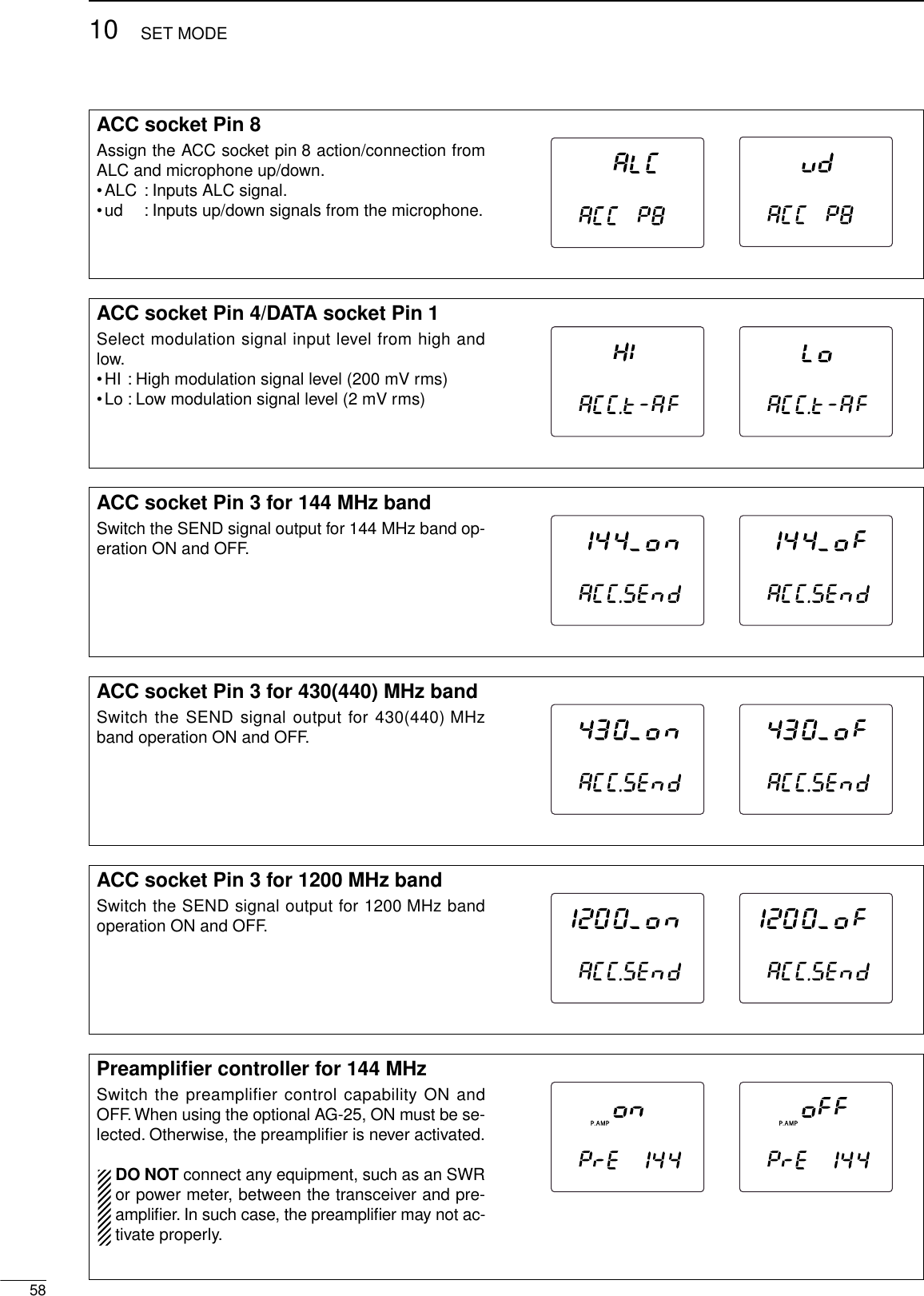
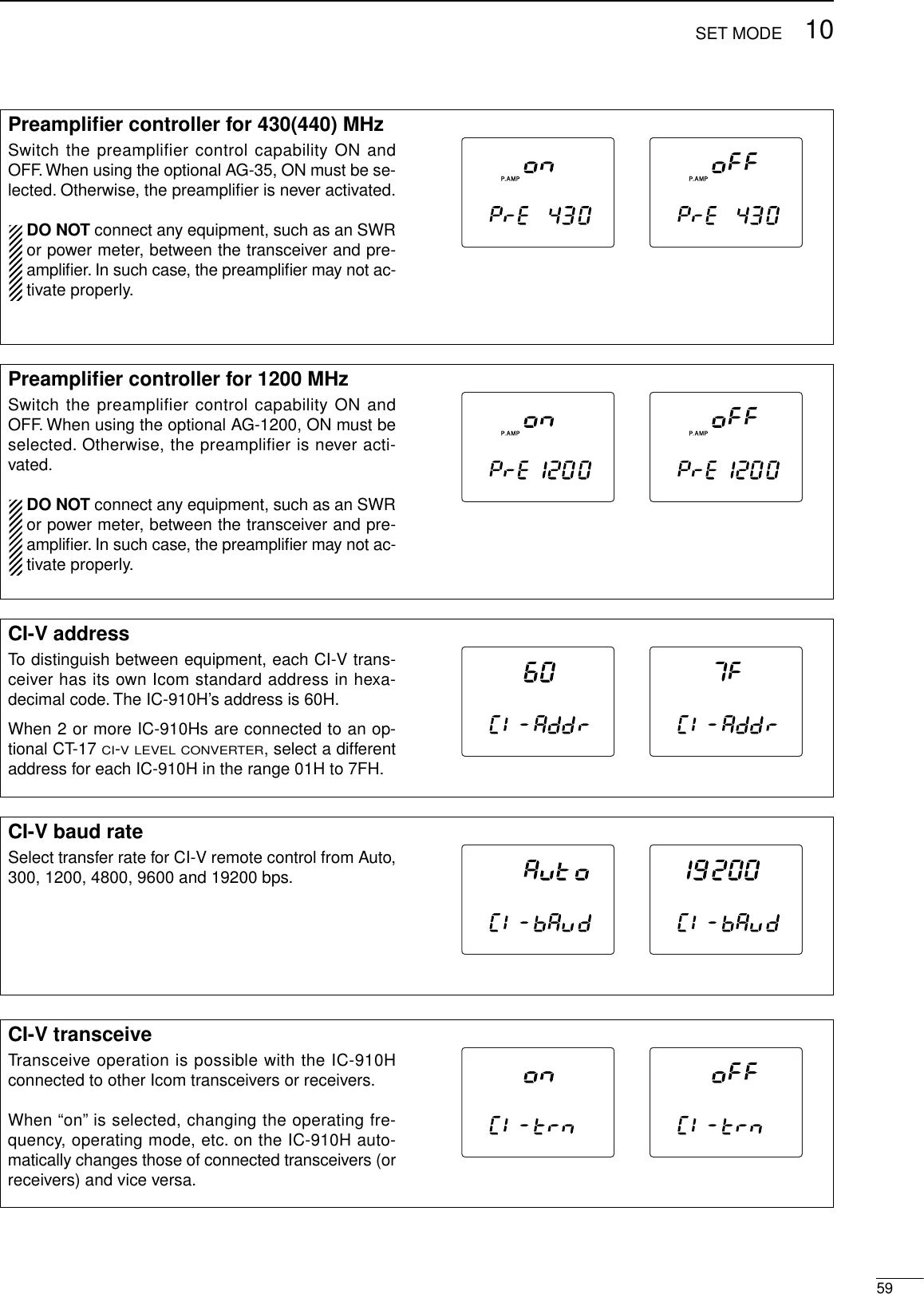
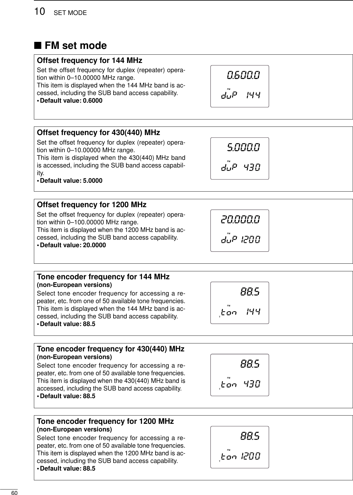
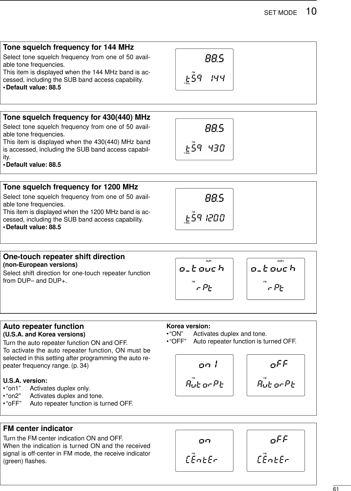
![6210 SET MODE■SSB/CW set modeSquelch threshold Select the squelch threshold level from 12 and 13 o’-clock.•12 : The squelch closes around the 12 o’clock po-sition of the [SQL] control.•13 : The squelch closes around the 13 o’clock po-sition of the [SQL] control.Carrier frequency Adjust the carrier frequency for SSB (USB/LSB)mode operation within –200 to +200 Hz range in10 Hz steps.LSBUSBLSBUSBCW pitch frequency Adjust the CW pitch frequency within 300 to 900 Hzrange in 10 Hz steps.CWCW keying speed adjustmentAdjust the built-in electric keyer keying speed to thedesired level within 6 to 60 WPM range.CW CWSemi break-inTurn the semi break-in function ON and OFF.CW CWCW break-in delayAdjust the CW break-in delay time to the desired levelwithin 2.0 to 13.0 sec. range in 0.1 sec. steps.CW CW](https://usermanual.wiki/ICOM-orporated/IC-910H/User-Guide-130522-Page-64.png)
![6310SET MODEAF control relationTurn the relation of [AF] control for CW side tone out-put level ON and OFF.•on : CW side tone output level is adjustable via[AF] control adjustment.•oFF : CW side tone output level is fixed regardlessof [AF] control setting.CW CWCW side tone output levelAdjust the CW side tone output to the desired levelwithin 0 (no output) to 100 (maximum output) range.CW CWKey typeSelect the key type from normal, reverse, bug, OFFand microphone [UP]/[DN].•n : Use built-in electronic keyer.•r : Use built-in electronic keyer with reversedpolarity.•buG : Use built-in electronic keyer as bug key.•oFF : Use external electronic keyer or straight key.•ud : Use microphone’s [UP]/[DN] as a paddle.CW CWCW dot-dash ratioAdjust the CW dot-dash ratio to the desired levelwithin 1:1:2.8 to 1:1:4.5 range.CWC/N type for 1200 MHzSelect the C/N type for the 1200 MHz band operationfrom type 1 and 2.•tyPE 1 : Provides better characteristics for nearby in-terference in FM mode operation.•tyPE 2 : Provides lower noise level just around thesignal in SSB/CW mode operation.This item is displayed only when the optional UX-910is installed.USBUSBLSBLSBCWFM](https://usermanual.wiki/ICOM-orporated/IC-910H/User-Guide-130522-Page-65.png)
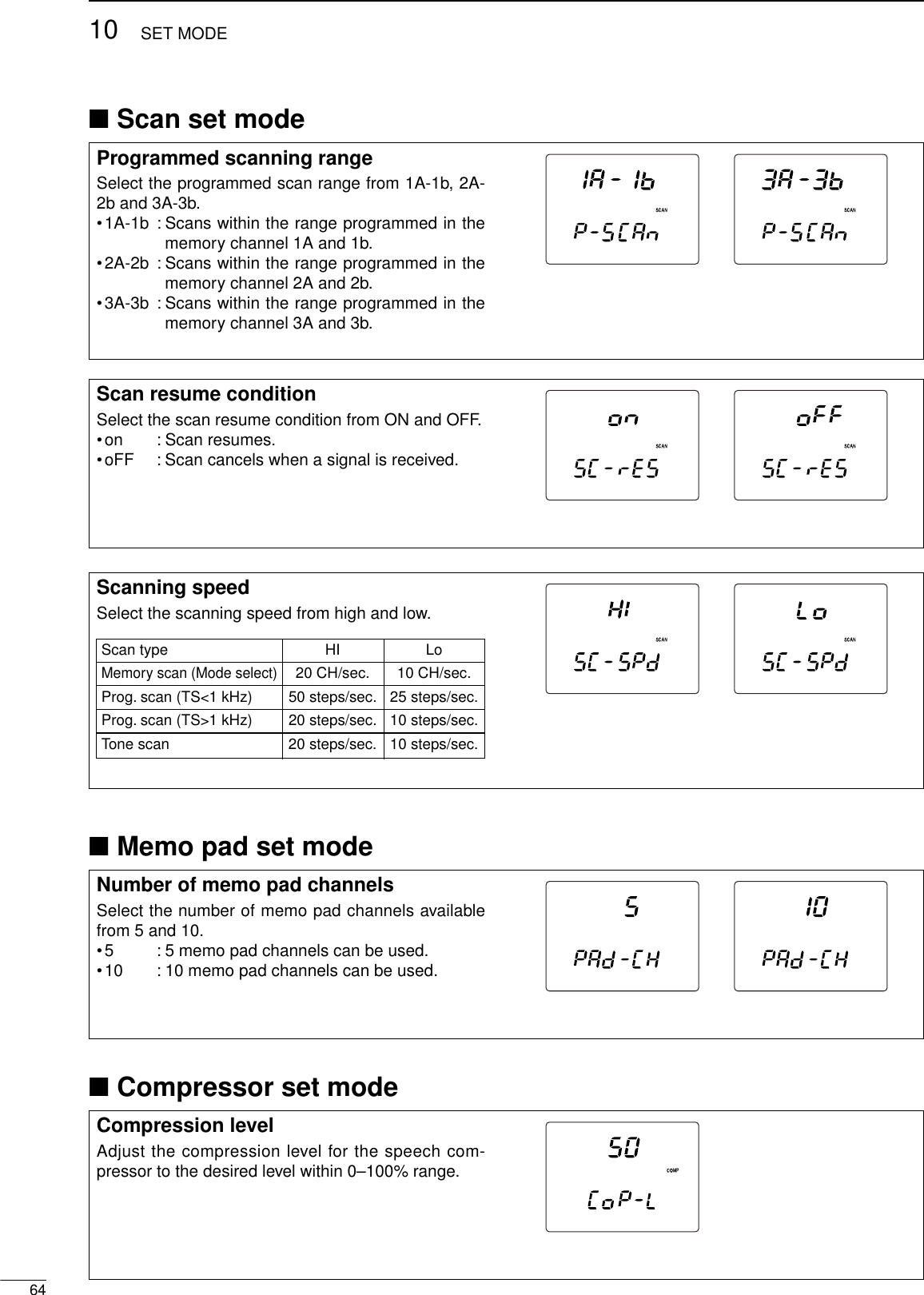
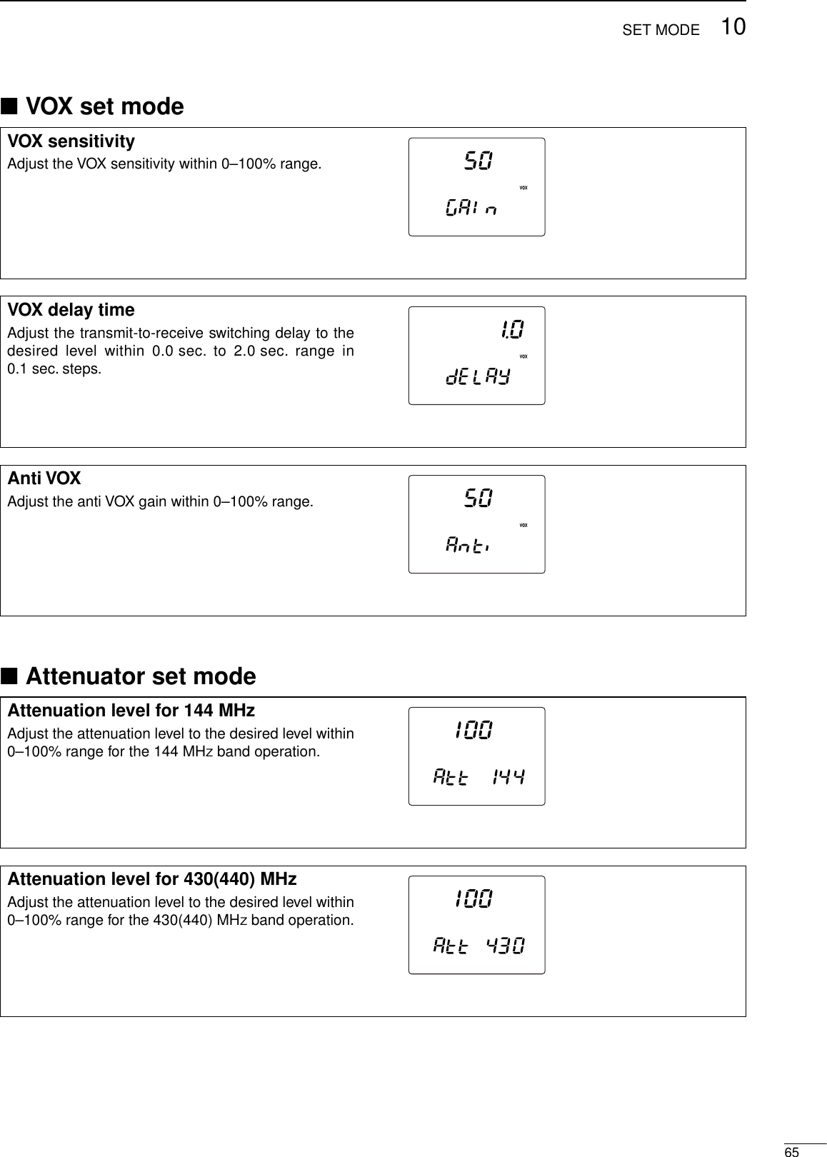
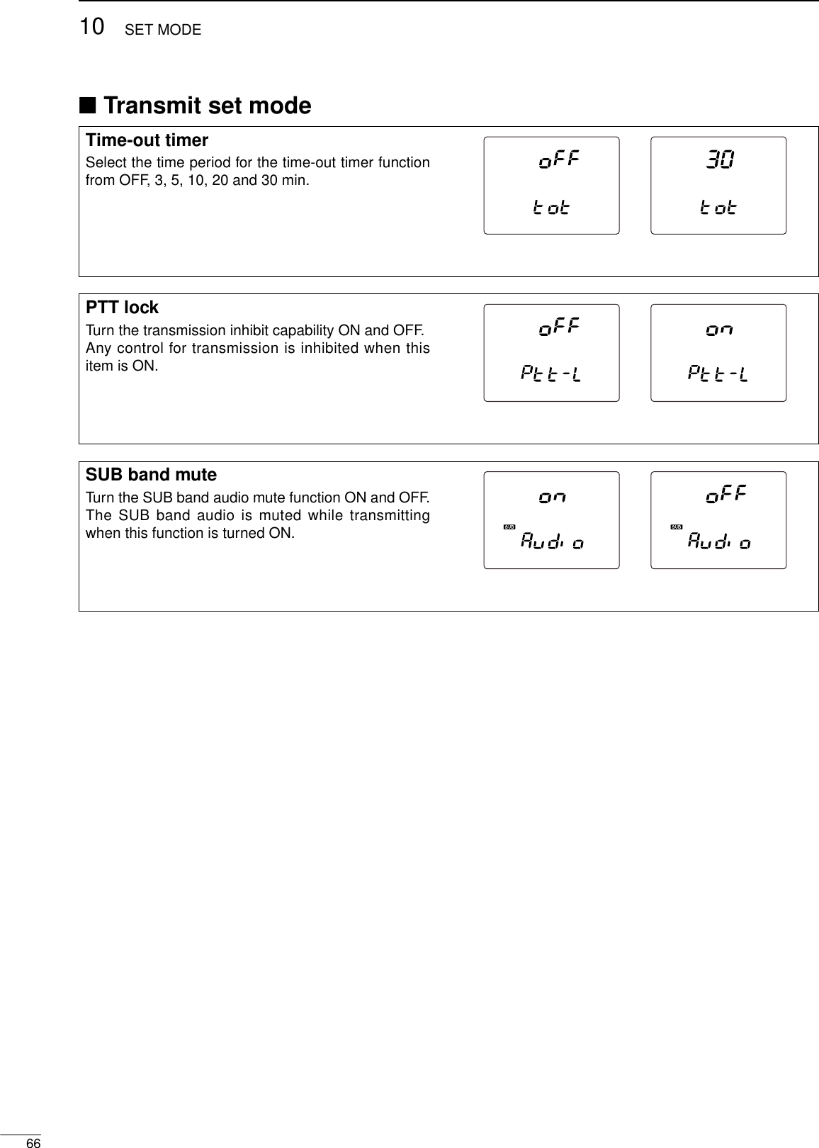
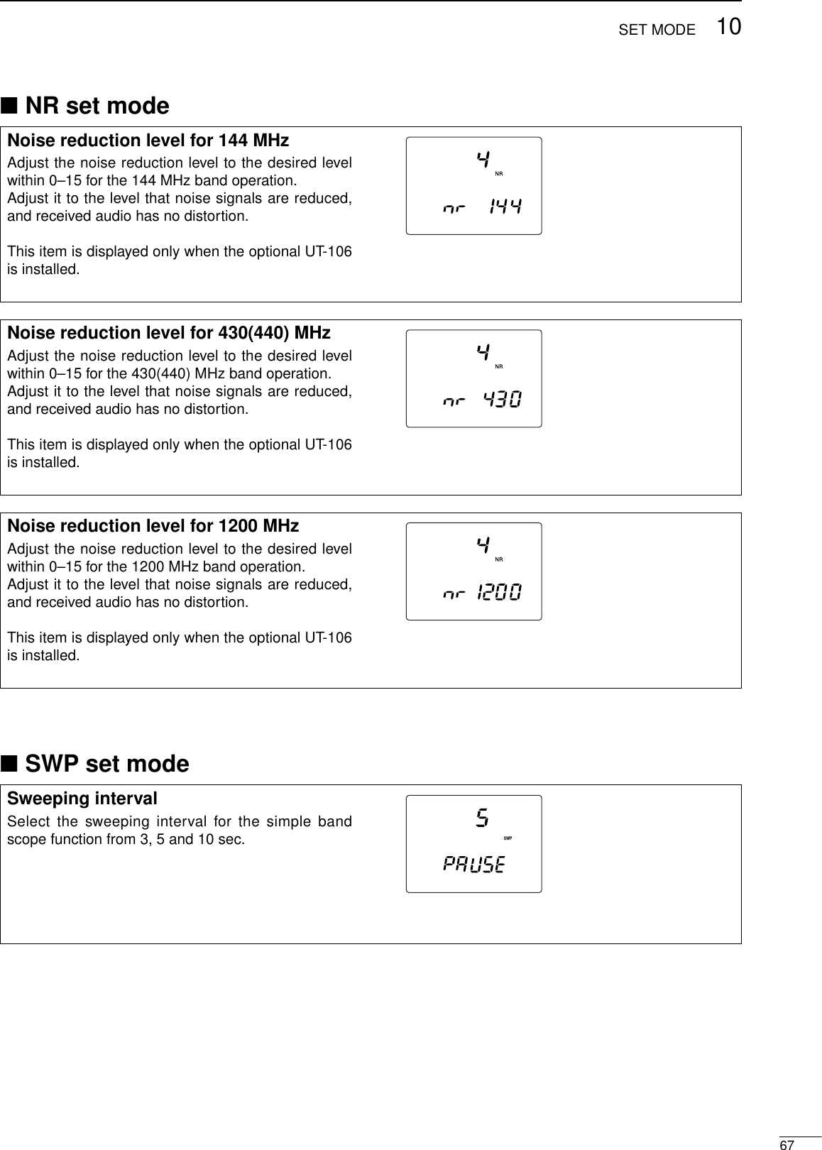
![■RIT/SHIFT set mode6810 SET MODERIT control assignmentAssign [RIT] control function from rit, dIAL, SubdIALand Sub-SFt.•rit : [RIT] control functions as RIT control.•dIAL : [RIT] control functions as tuning dial forMAIN band.•SubdIAL : [RIT] control functions as tuning dial forSUB band.•Sub-SFt : [RIT] control functions as IF shift controlfor SUB band.SHIFT control assignmentAssign [SHIFT] control function from SFt, Sub-SFt,dIAL and SubdIAL.•SFt : [SHIFT] control functions as IF shift con-trol.•Sub-SFt : [SHIFT] control functions as IF shift con-trol for SUB band.•dIAL : [SHIFT] control functions as tuning dialfor MAIN band.•SubdIAL : [SHIFT] control functions as tuning dialfor SUB band.RIT indicationTurn the RIT adjusting value indication ON and OFF.The value is displayed while adjusting when this func-tion is turned ON.](https://usermanual.wiki/ICOM-orporated/IC-910H/User-Guide-130522-Page-70.png)
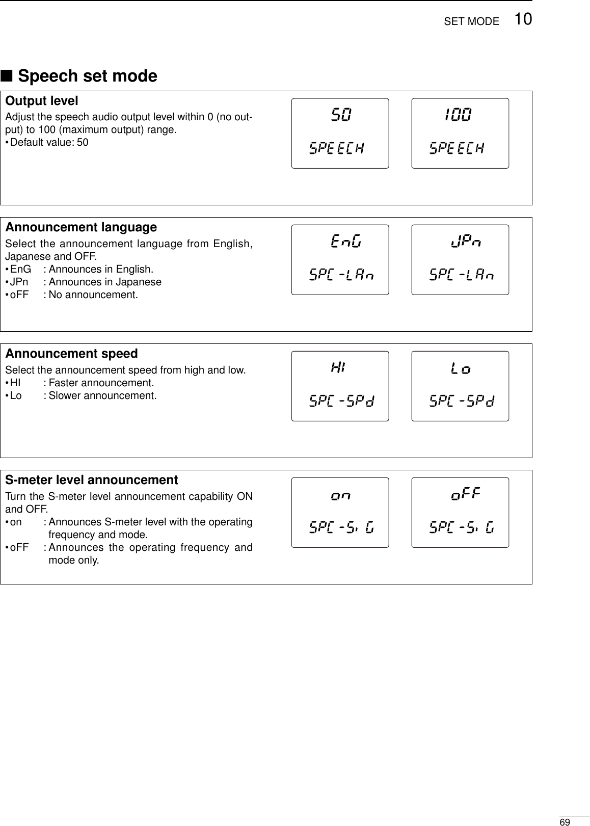
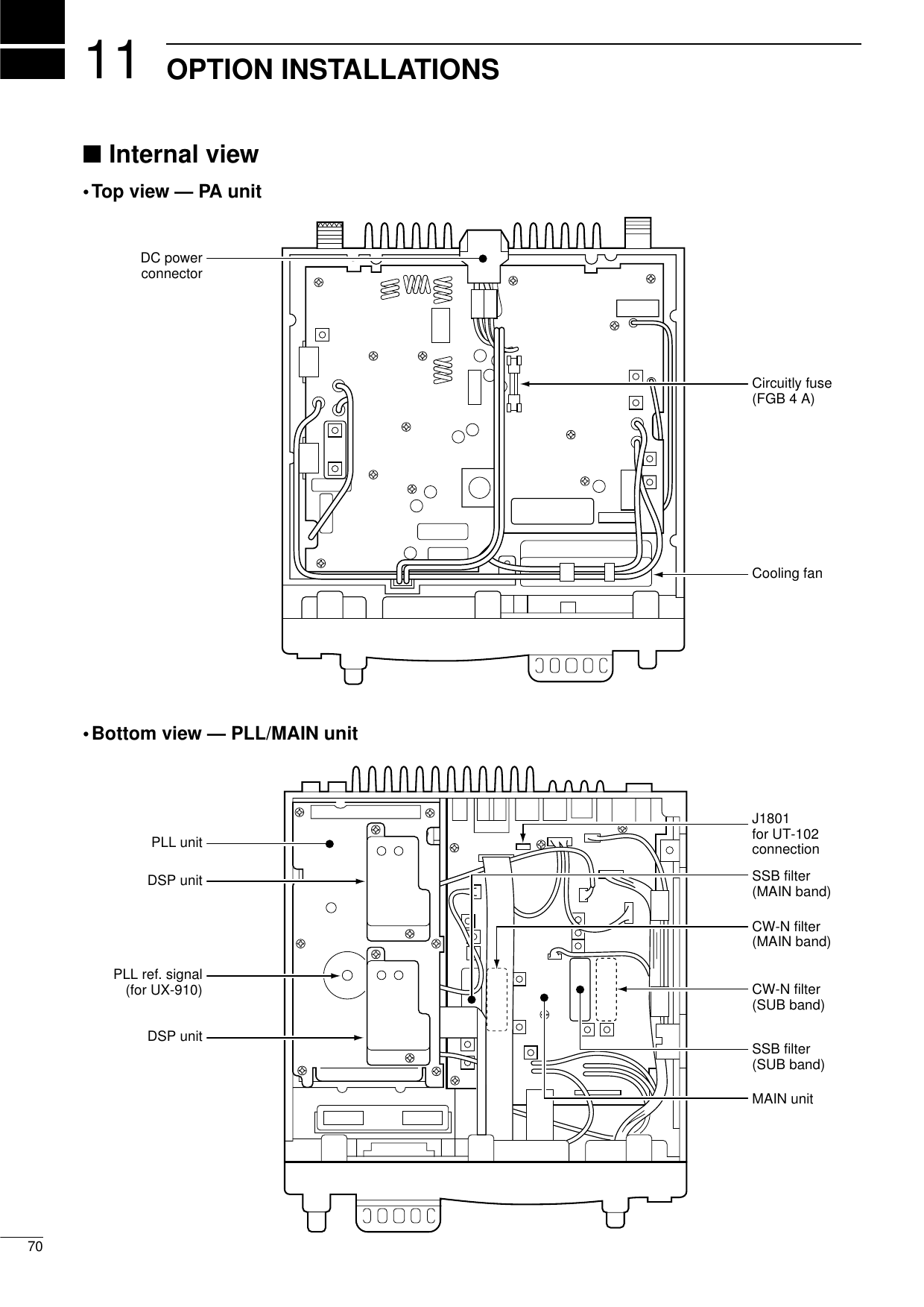
![Follow the case and cover opening proceduresshown here when you want to install an optionalunit or adjust the internal units, etc.qRemove the 5 screws from the top of thetransceiver and the 4 screws from the sides,then lift up the top cover.wTurn the transceiver upside down.eRemove the 5 screws from the bottom of thetransceiver, then lift up the bottom cover.CAUTION: DISCONNECT the DC powercable from the transceiver before performingany work on the transceiver. Otherwise, thereis a danger of electric shock and/or equipmentdamage.Disconnect the speaker cable.7111OPTION INSTALLATIONS■Opening the transceiver’s caseThe UT-102 announces the accessed readout’s fre-quency, mode, etc. (S-meter level can also be an-nounced—p. 69) in a clear, electronically-generatedvoice, in English (or Japanese).➥Push [SPCH] to announce the frequency, etc.qRemove the bottom cover as shown above.•Remove the UX-910 if you have installed it. (p. 73)wRemove the protective paper attached to the bottomof the UT-102 to expose the adhesive strip.ePlug UT-102 into J1801 on the MAIN unit as shownin the diagram at right.rReturn the bottom cover to its original position.tSet the speech level, announcement language andS-meter announcement in the speech set mode(p. 69) if desired.UT-102MAIN unitJ1801■UT-102 VOICE SYNTHESIZER UNIT◊Opening the PA unit coverqRemove the 8 screws and grounding plate from thePA unit cover.wRemove fastening tape from the inside power cable.eSlide the PA unit cover as shown below.grounding plate](https://usermanual.wiki/ICOM-orporated/IC-910H/User-Guide-130522-Page-73.png)
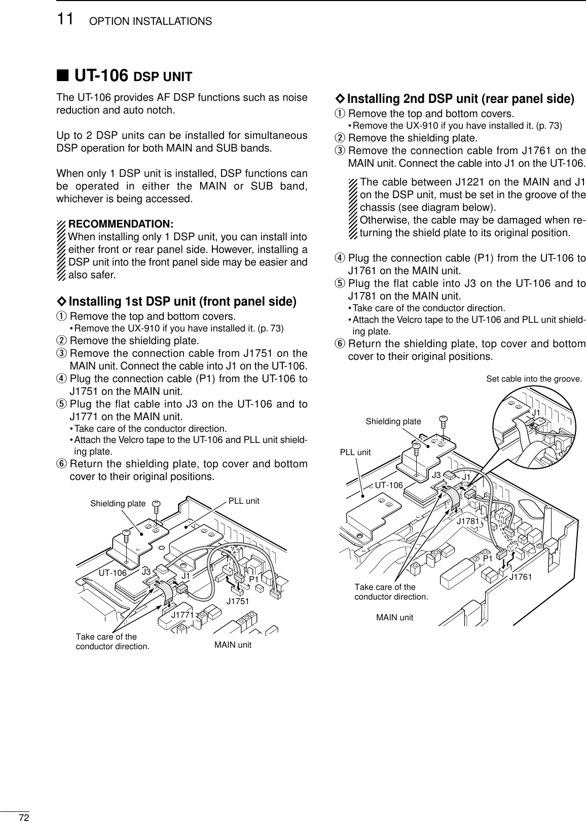
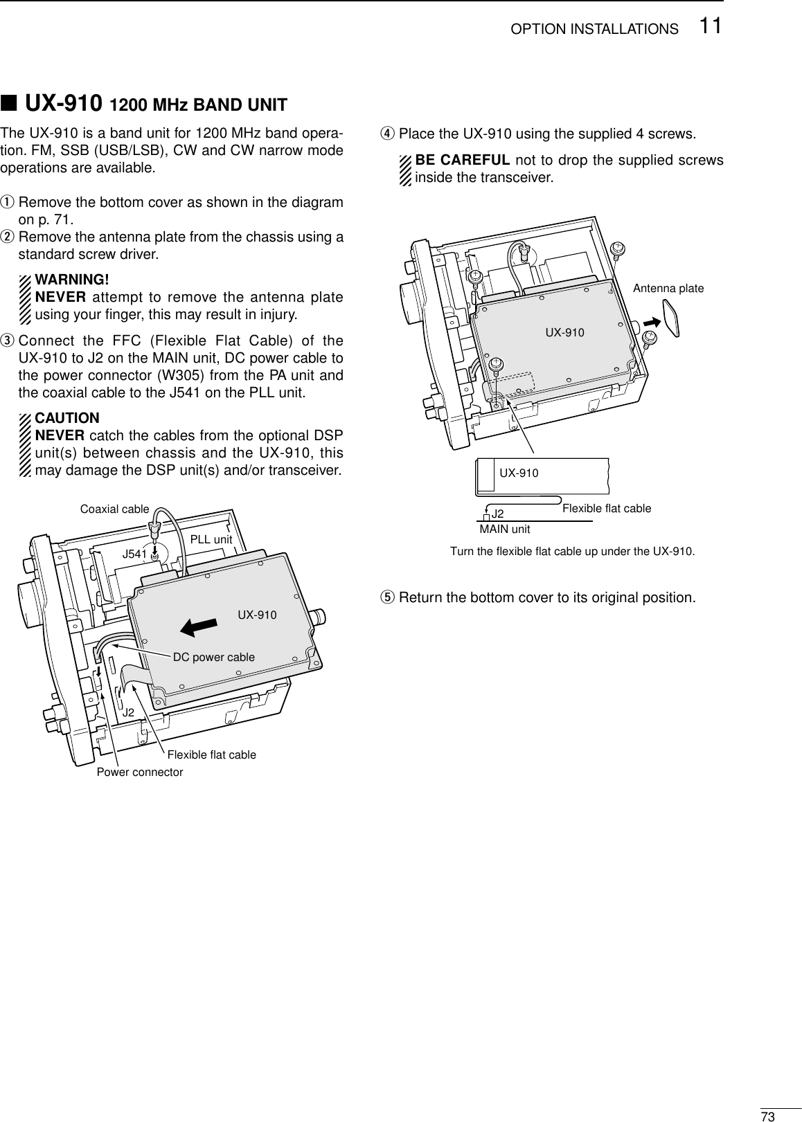
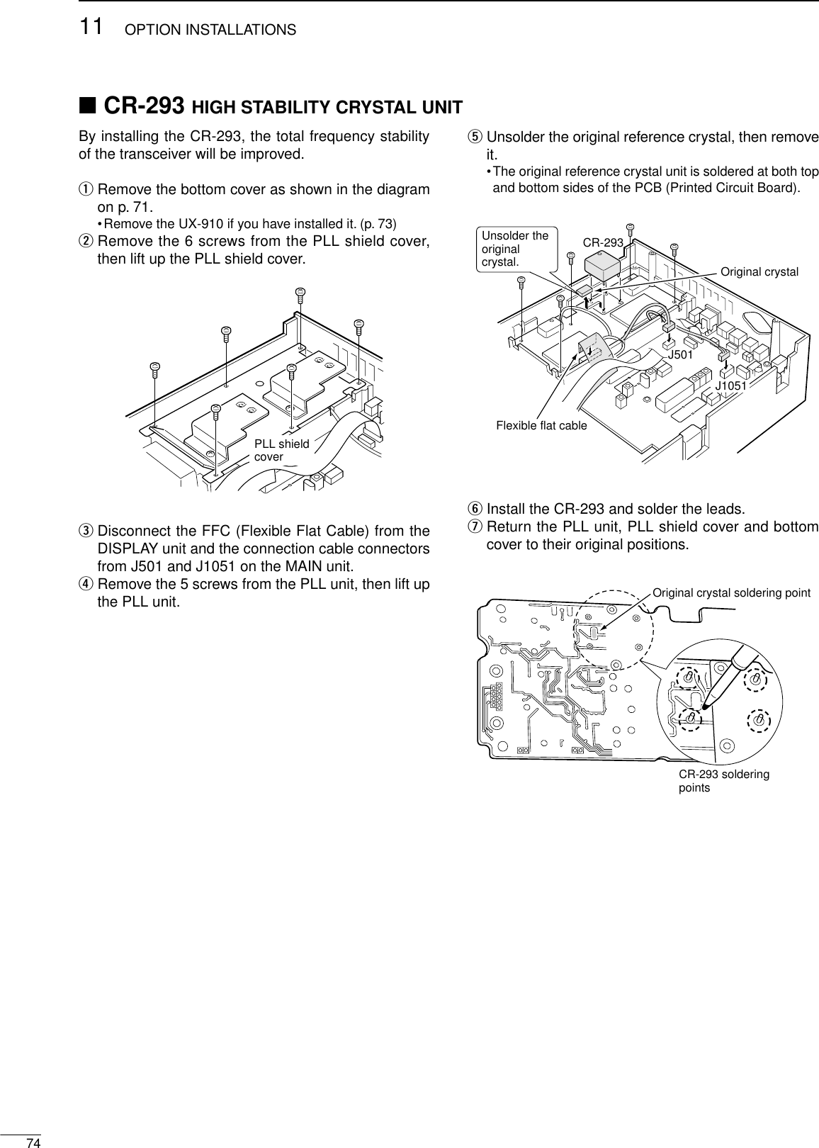
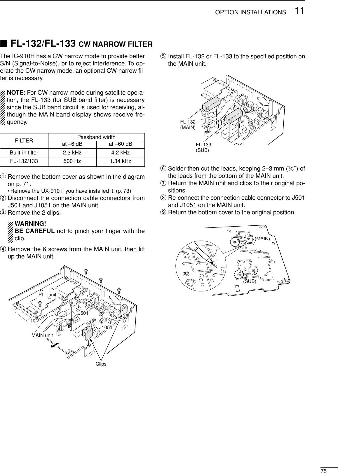
![POWERRECEIVETRANSMITSCANDISPLAYPROBLEM POSSIBLE CAUSE SOLUTION REF.SPEECH1176MAINTENANCE■TroubleshootingThe following chart is designed to help you correctproblems which are not equipment malfunctions. If you are unable to locate the cause of a problem orsolve it through the use of this chart, contact your near-est Icom Dealer or Service Center.Power does not come onwhen [POWER] is pushed.No sounds comes fromthe speaker.Sensitivity is low.Received audio is dis-torted.Transmitting is impossible.Output power is too low.No contact possible withanother station.Transmitted signals aredistorted.Repeater cannot be ac-cessed.Programmed scan doesnot start.Memory scan does notstart.Mode select scan does notstart.No announcement when[SPCH] is pushed.The displayed frequencydoes not change properly.•DC power cable is improperly connected.•Fuse is blown.•Volume level is too low.•The squelch is closed.•The transceiver is in the transmitting condition.•The antenna is not connected properly.•The attenuator is activated.•The S-meter squelch is activated.•Incorrect sideband (USB/LSB) is selected.•Receiving an FM signal.•Noise blanker is activated.•Noise reduction is activated.•PTT lock function is activated.•[RF PWR] is set too far counterclockwise.•[MIC GAIN] is set too far counterclockwise.•Split frequency operation or duplex operation isactivated.•RIT function is activated.•[MIC GAIN] to far clockwise.•Duplex operation is not activated.•No subaudible tone or incorrect tone frequencyis selected.•VFO mode is not selected.•[RF/SQL] is assigned to RF gain and squelch isopened.•Memory mode is not selected.•No memory channels are programmed.•Mode select scan mode has not been selected.•Only one channel is programmed with the se-lected operating mode.•The voice synthesizer unit has not been in-stalled.•The announcement level is set to “0”or too low.•The announcement language is set to “oFF.”•The dial lock function is activated.•The internal CPU has malfunctioned.•Reconnect the DC power cable correctly.•Check the cause, then replace the fuse with aspare one. (Fuses are installed in the DC powercable and the internal PA unit.)•Rotate [AF] clockwise to obtain a suitable listen-ing level.•Rotate [RF/SQL] to 12 o’clock position to openthe squelch.•Push [TRANSMIT] to receive or check the SENDline of an external unit, if desired.•Reconnect to the antenna connector.•Push [ATT] to turn the attenuator OFF.•Rotate [RF/SQL] to the position where the noisejust disappears.•Switch USB and LSB by pushing [SSB/CW] for1 sec.•Push [FM] to select FM mode.•Push [AFC/NB] to turn the noise blanker functionOFF.•Set the noise reduction level in the NR set modefor maximum readability using [SET] and[AFC/NB•NR], or turn OFF the function by push-ing [AFC/NB•NR] for 1 sec.•Turn the PTT lock function OFF in the TRANSMITset mode using [SET] and [TRANSMIT].•Rotate [RF PWR] clockwise.•Rotate [MIC GAIN] clockwise.•Push [SPLIT] momentarily or for 1 sec. to turn thesplit or duplex function OFF.•Push [RIT] to turn the RIT function OFF.•Set [MIC GAIN] to a suitable level.•Push [SPLIT•DUP] for 1 sec. to turn duplex oper-ation ON.•Push [TONE] to activate the subaudible tone orselect a suitable tone frequency in the FM setmode using [SET] and [FM].•Push [V/M 1] to select VFO mode.•Reset [RF/SQL] control assignment and set it tothe threshold point.•Push [V/M 1] to select memory mode.•Program desired frequencies into memory chan-nels.•Push [SPCH•LOCK] for 1 sec. on the desired op-erating mode programmed channel.•Program more than two channels with the desiredoperating mode.•Install the optional vice synthesizer unit, UT-102.•Set the announcement level to a suitable level inthe SPCH set mode using [SET] and [SPCH].•Set the announcement language to “Eng”(or JPn)in the SPCH set mode using [SET] and [SPCH].•Push [SPCH•LOCK] to turn the lock function OFF.•Reset the CPU.–p. 77p. 26p. 26pgs.2, 13–p. 29p. 26p. 23p. 23p. 30p. 31p. 66p. 32p. 32p. 37p. 27p. 32p. 34p. 35p. 21p. 26p. 40p. 41p. 47p. 41p. 71p. 69p. 69p. 25p. 77](https://usermanual.wiki/ICOM-orporated/IC-910H/User-Guide-130522-Page-78.png)
![7711MAINTENANCE■Fuse replacementIf a fuse blows or the transceiver stops functioning, tryto find the source of the problem, and replace the dam-aged fuse with a new, rated fuse.CAUTION: DISCONNECT the DC power cablefrom the transceiver when changing a fuse.The IC-910H has 2 types of fuses installed for trans-ceiver protection.•DC power cable fuses ................................FGB 30 A•Circuitry fuse ................................................FGB 4 ADC POWER CABLE FUSE REPLACEMENT30 A fuseCIRCUITRY FUSE REPLACEMENTThe 13.8 V DC from the DC power cable is applied toall units in the IC-910H, except for the power ampli-fier, through the circuitry fuse. This fuse is installed inthe PA unit.qRemove the top cover as shown on p. 71.wRemove the 11 screws from the PA shielding plate,then remove the plate.eReplace the circuitry fuse as shown in the diagramat right.rReplace the PA shielding plate and top cover.Circuitry fuse (4 A)■CPU resettingResetting CLEARS all programmed contents inmemory channels and returns programmed valuesin set mode to default values.When first applying power or when the functionseems to be displaying erroneous information, resetthe CPU as follows:qMake sure the transceiver power is OFF.wWhile pushing [MW 4] and [M-CL 5], push[POWER] to turn power ON.•The internal CPU is reset.•The transceiver displays its initial VFO frequencieswhen resetting is complete.[POWER] [MW 4] [M-CL 5]](https://usermanual.wiki/ICOM-orporated/IC-910H/User-Guide-130522-Page-79.png)
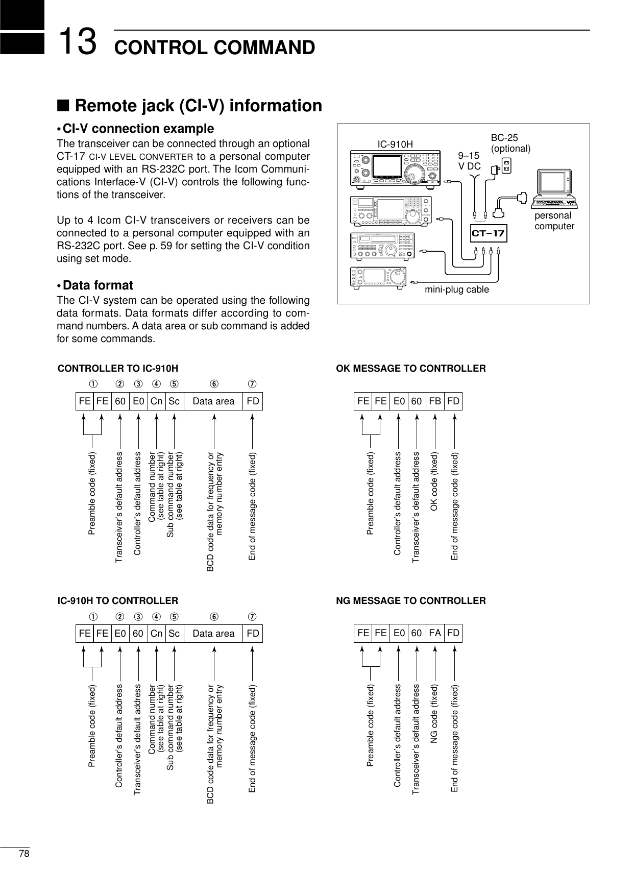
![7913CONTROL COMMANDCommandSub command00 —01 ××02 —03 —04 —05 —0006 010304—000107 A0B0D0D1—01–0106*0809 —0A —0B —0C —0D —000E 01D0D300010F 101112000102030410 0506070809101111 0020DescriptionSend frequency data for trans-ceive.Send mode data for transceive.Read band edge frequencies.Read operating frequency data.Read operating mode data.Set operating frequency.Set LSB.Set USB.Set CW.Set FM.Select VFO mode.Select VFO A.Select VFO B.Equalize VFO A and VFO B.Switch VFO A and VFO B.Select MAIN VFO.Select SUB VFO.Select memory mode.Select memory channel.*1A=0100 1b=01012A=0102 2b=01033A=0104 3b=0105Call=0106Memory write.Transfer memory contents toVFO.Memory clear.Read duplex offset frequency.Set duplex offset frequency.Cancel scan.Start scan.Set scan resume OFF.Set scan resume ON.Turn the split function OFF.Turn the split function ON.Set simplex operation.Set DUP– operation.Set DUP+ operation.Set 1 Hz tuning step.Set 10 Hz tuning step.Set 50 Hz tuning step.Set 100 Hz tuning step.Set 1 kHz tuning step.Set 5 kHz tuning step.Set 6.25 kHz tuning step.Set 10 kHz tuning step.Set 12.5 kHz tuning step.Set 20 kHz tuning step.Set 25 kHz tuning step.Set 100 kHz tuning step.Turn attenuator OFF.Turn attenuator ON.CommandSub command00130102010203040614 090A0B0C0E0F01150202122240 +level data4116 42434446474A19 00000102+level data03+level data041A +level data05+level data060708DescriptionAnnounce all S-meter levels,displayed frequency and mode.Announce displayed frequency.Announce operating mode.[AF] level setting (0=max. CCW;128=center; 255=max. CW).[RF GAIN] level setting (0=max. CCW; 255=max. CW).[SQL] level setting (0=max.CCW; 255=max. CW).[IF SHIFT] level setting (0=max.CCW; 128=center; 255=max. CW).Set noise reduction level(0=0%; 255=100%).Set CW pitch (0=300 Hz;255=900 Hz).[RF PWR] level setting (0=max.CCW; 128=center; 255=max. CW).[MIC GAIN] level setting (0=max.CCW; 128=center; 255=max. CW).Key speed setting (0=6 wpm;255=60 wpm).Set mic. compressor level(0=0%; 255=100%).Set break-in delay (0=2.0 sec;255=13.0 sec.).Read squelch condition (openor closed).Read S-meter level.Set pre-amp (0=OFF; 1=ON).Set AGC (0=Slow; 1=Fast).Set noise blanker (0=OFF; 1=ON).Set noise reduction level(0=OFF; 1–15=ON).Set auto notch filter (0=OFF; 1=ON).Set subaudible tone (0=OFF; 1=ON).Set tone squelch (0=OFF; 1=ON).Set mic. compressor (0=OFF; 1=ON).Set VOX (0=OFF; 1=ON).Set break-in (0=OFF; 1=ON).Set AFC (0=OFF; 1=ON).Read the transceiver ID.Read/write memory channel.Set satellite memory.Set VOX gain level (0=0%; 255=100%).Set VOX delay (0=0 sec.; 20=2.0 sec.).Set anti-VOX (0=0%; 255=100%).Attenuation level setting(0=0%; 255=100%).Set RIT (0=OFF; 1=ON; 2=Sub dial).Set satellite mode (0=OFF; 1=ON).Set simple bandscope (0=OFF; 1=ON).](https://usermanual.wiki/ICOM-orporated/IC-910H/User-Guide-130522-Page-81.png)
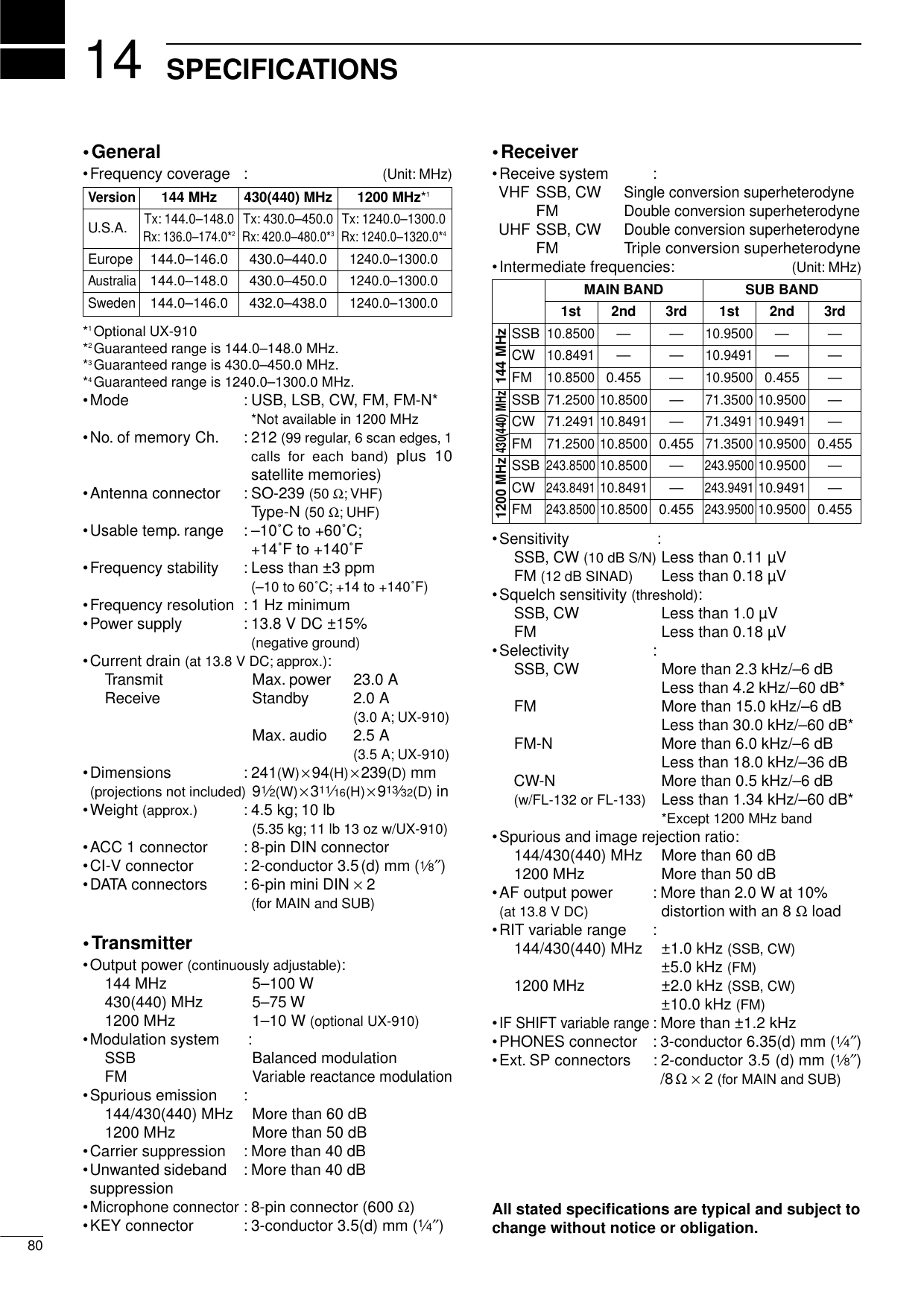
![1581OPTIONSSM-20 DESKTOP MICROPHONEUnidirectional, electret microphone forbase station operation. Includes [UP]and [DOWN] switches and a low cutfunction.SP-21 EXTERNAL SPEAKERDesigned for base station operation.•Input impedance: 8 Ω•Max. input power: 5 WCT-17 CI-V LEVEL CONVERTERFor remote transceiver control using apersonal computer. You can changefrequencies, operating mode, memorychannels, etc.HM-12 HAND MICROPHONEHand microphone equipped with[UP]/[DOWN] switches. Same as thatsupplied with the transceiver.CR-293 HIGH STABILITY CRYSTAL UNITFrequency stability: ±0.5 ppm (0˚C to +60˚C)FL-132 (for MAIN band)FL-133 (for SUB band and satelliteoperation)CW NARROW FILTERSHave good shape factor and providebetter CW reception during crowdedband conditions. 500 Hz/–6dBMB-23 CARRYING HANDLECarrying handle, convenient forportable operation.UX-910 1200 MHz BAND UNITAllows you additional all mode opera-tion on the 1200 MHz band.UT-106 DSP UNITAllows AF DSP capabilities, includingnoise reduction and auto notch filter.AG-25 (for 144 MHz band),AG-35 (for 430(440) MHz band), AG-1200 (for 1200 MHz band)WEATHER-PROOF PREAMPLIFIERSExternal all-weather, mast mounting preamplifiers for com-pensating for coaxial cable loss.IC-MB5 MOBILE MOUNTING BRACKETTransceiver mounting bracket for mobile operation.SP-7 EXTERNAL SPEAKERCompact speaker for base station operation.UT-102 VOICE SYNTHESIZER UNITAnnounces the receive frequency, mode and S-meter levelin a clear, electronically-generated voice, in English (orJapanese).](https://usermanual.wiki/ICOM-orporated/IC-910H/User-Guide-130522-Page-83.png)