ICOM orporated IC-910H Amature Scanning Transceiver User Manual IC 910H 2
ICOM Incorporated Amature Scanning Transceiver IC 910H 2
Manual
INSTRUCTION MANUAL
VHF/UHF
ALL MODE TRANSCEIVER
i910H

IMPORTANT
READ THIS INSTRUCTION MANUAL
CAREFULLY before attempting to operate the
transceiver.
SAVE THIS INSTRUCTION MANUAL. This
manual contains important safety and operating in-
structions for the IC-910H.
EXPLICIT DEFINITIONS
i
RWARNING HIGH VOLTAGE! NEVER attach
an antenna or internal antenna connector during trans-
mission. This may result in an electrical shock or burn.
RNEVER apply AC to the [DC13.8V] jack on the
transceiver rear panel. This could cause a fire or ruin
the transceiver.
RNEVER apply more than 16 V DC, such as a 24 V
battery, to the [DC13.8V] jack on the transceiver rear
panel. This could cause a fire or ruin the transceiver.
RNEVER let metal, wire or other objects touch any
internal part or connectors on the rear panel of the
transceiver. This may result in an electric shock.
RNEVER expose the transceiver to rain, snow or
any liquids.
AVOID using or placing the transceiver in areas with
temperatures below –10°C (+14°F) or above +60°C
(+140°F). Be aware that temperatures on a vehicle’s
dashboard can exceed 80°C (+176°F), resulting in per-
manent damage to the transceiver if left there for ex-
tended periods.
AVOID placing the transceiver in excessively dusty en-
vironments or in direct sunlight.
AVOID placing the transceiver against walls or putting
anything on top of the transceiver. This will obstruct
heat dissipation.
Place unit in a secure place to avoid inadvertent use
by children.
During mobile operation, DO NOT operate the trans-
ceiver without running the vehicle’s engine. When the
transceiver power is ON and your vehicle’s engine is
OFF, the vehicle’s battery will soon become exhausted.
Make sure the transceiver power is OFF before start-
ing the vehicle. This will avoid possible damage to the
transceiver by ignition voltage spikes.
During maritime mobile operation, keep the transceiver
and microphone as far away as possible from the mag-
netic navigation compass to prevent erroneous indica-
tions.
BE CAREFUL! The heatsink will become hot when
operating the transceiver continuously for long periods.
BE CAREFUL! If a linear amplifier is connected, set
the transceiver’s RF output power to less than the lin-
ear amplifier’s maximum input level, otherwise, the lin-
ear amplifier will be damaged.
Use Icom microphones only (supplied or optional).
Other manufacturer’s microphones have different pin
assignments, and connection to the IC-910H may
damage the transceiver.
PRECAUTIONS
Versions of the IC-910H which display the “CE”
symbol on the serial number seal, comply with the
European harmonised standard ETS300 684
(EMC product standard for Commercially Available
Amateur Radio Equipment).
WORD
R
WARNING
CAUTION
NOTE
DEFINITION
Personal injury, fire hazard or electric
shock may occur.
If disregarded, inconvenience only.
No risk of personal injury, fire or
electric shock.
Equipment damage may occur.

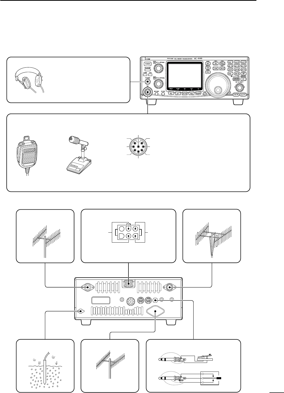
SUPPLIED ACCESSORIES
The transceiver comes with the following accessories.
Qty.
qDC power cable (OPC-657A) ............................ 1
wHand microphone (HM-12) ................................ 1
eSpare fuses (FGB 30 A) .................................... 2
rSpare fuse (FGB 4 A) ........................................ 1
1
1
TABLE OF CONTENTS
qwe
r
IMPORTANT ........................................ i
EXPLICIT DEFINITIONS ..................... i
PRECAUTIONS ................................... i
1 TABLE OF CONTENTS ................ 1
2 PANEL DESCRIPTION ........... 2–13
■Front panel ..................................... 2
■Function display ........................... 10
■Rear panel .................................... 12
3 INSTALLATION AND
CONNECTIONS ................... 14–17
■Unpacking .................................... 14
■Grounding ..................................... 14
■Selecting a location ...................... 14
■Antenna connection ..................... 14
■Required connections ................... 15
■Advanced connections ................. 16
■Power supply connections ............ 17
4 BASIC OPERATION ............. 18–25
■Initial settings ................................ 18
■When first applying power
(CPU resetting) ............................. 18
■MAIN and SUB bands .................. 19
■Operating band selection ............. 20
■VFO description ............................ 21
■Frequency setting ......................... 22
■SUB band OFF ............................. 24
■SUB tuning dial ............................. 24
■Dial lock function .......................... 25
5 RECEIVE AND TRANSMIT .. 26–39
■Functions for receive .................... 26
■RIT function .................................. 27
■IF shift function ............................. 27
■AGC time constant ....................... 28
■AFC function ................................. 28
■FM center indicator ....................... 28
■Attenuator ..................................... 29
■Simple band scope ....................... 29
■Noise blanker ............................... 30
■Tone squelch operation ................ 30
■Optional DSP functions ................ 31
■Functions for transmit ................... 32
■Transmit via microphone ............... 32
■Indications during transmit ........... 32
■FM mode operation ...................... 33
■VOX operation .............................. 33
■Repeater operation ....................... 34
■SSB mode operation .................... 36
■Speech compressor ..................... 36
■Split frequency operation .............. 37
■Full duplex operation .................... 37
■Connections for CW ..................... 38
■CW mode operation ..................... 38
6 MEMORY OPERATION ........ 40–44
■Memory channels ......................... 40
■Operation on a memory channel .. 40
■Programming in VFO mode .......... 41
■Programming in memory mode .... 41
■Blank channels ............................. 42
■Frequency transferring ................. 42
■Memory clearing ........................... 43
■Call channels ................................ 43
■Memo pads ................................... 44
7 SCANS ................................. 45–47
■Scan types .................................... 45
■Preparation ................................... 45
■Programmed scan operation ........ 46
■Memory scan operation ................ 46
■Memory select scan ..................... 47
■Tone scan ..................................... 47
8 SATELLITE OPERATION ..... 48–51
■Satellite communications outline .. 48
■Satellite notes ............................... 48
■Entering into the satellite mode .... 48
■Setting the satellite VFO ............... 49
■Tracking selection ......................... 49
■Preparation ................................... 50
■Satellite operation ......................... 51
■Satellite memory .......................... 51
9 DATA COMMUNICATION ..... 52–54
■Functions for AFSK ...................... 52
■Connections for AFSK .................. 52
■Operating mode notes .................. 53
■Operating frequency notes ........... 53
■AFSK operation ............................ 53
■Setting the ACC socket ................ 54
10 SET MODE ........................... 55–69
■Set mode description ................... 55
■General set mode ......................... 56
■FM set mode ................................ 60
■SSB/CW set mode ....................... 62
■Scan set mode ............................. 64
■Memo pad set mode ..................... 64
■Compressor set mode .................. 64
■VOX set mode .............................. 65
■Attenuator set mode ..................... 65
■Transmit set mode ........................ 66
■NR set mode ................................ 67
■SWP set mode ............................. 67
■RIT/SHIFT set mode .................... 68
■Speech set mode ......................... 69
11 OPTION INSTALLATIONS ... 70–76
■Internal view ................................. 70
■Opening the transceiver’s case .... 71
■UT-102 VOICE SYNTHESIZER
UNIT .............................................. 71
■UT-106 DSP UNIT .......................... 72
■UX-910 1200 MHz BAND UNIT ........ 73
■CR-293 HIGH STABILITY CRYSTAL
UNIT .............................................. 74
■FL-132/FL-133 CW NARROW
FILTER ........................................... 75
12 MAINTENANCE ................... 76–77
■Troubleshooting ............................ 76
■Fuse replacement ......................... 77
■CPU resetting ............................... 77
13 CONTROL COMMAND ........ 78–79
■Remote jack (CI-V) information .... 78
14 SPECIFICATIONS ....................... 80
15 OPTIONS ..................................... 81
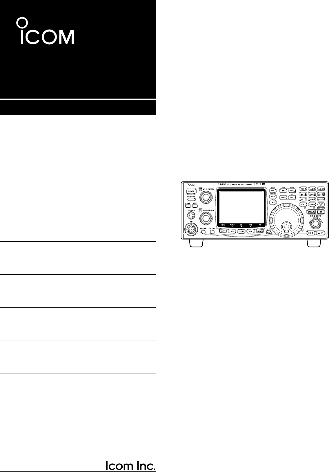
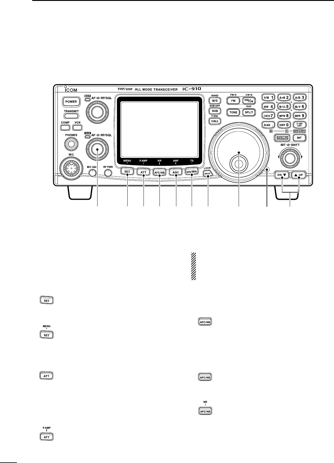
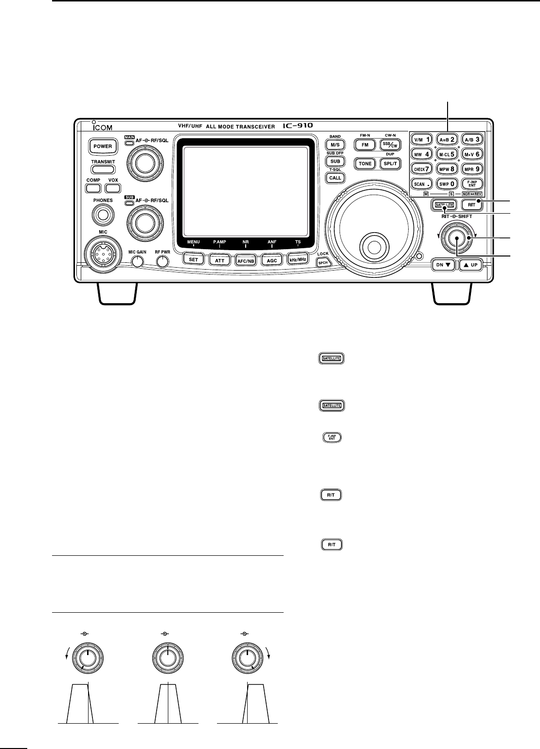
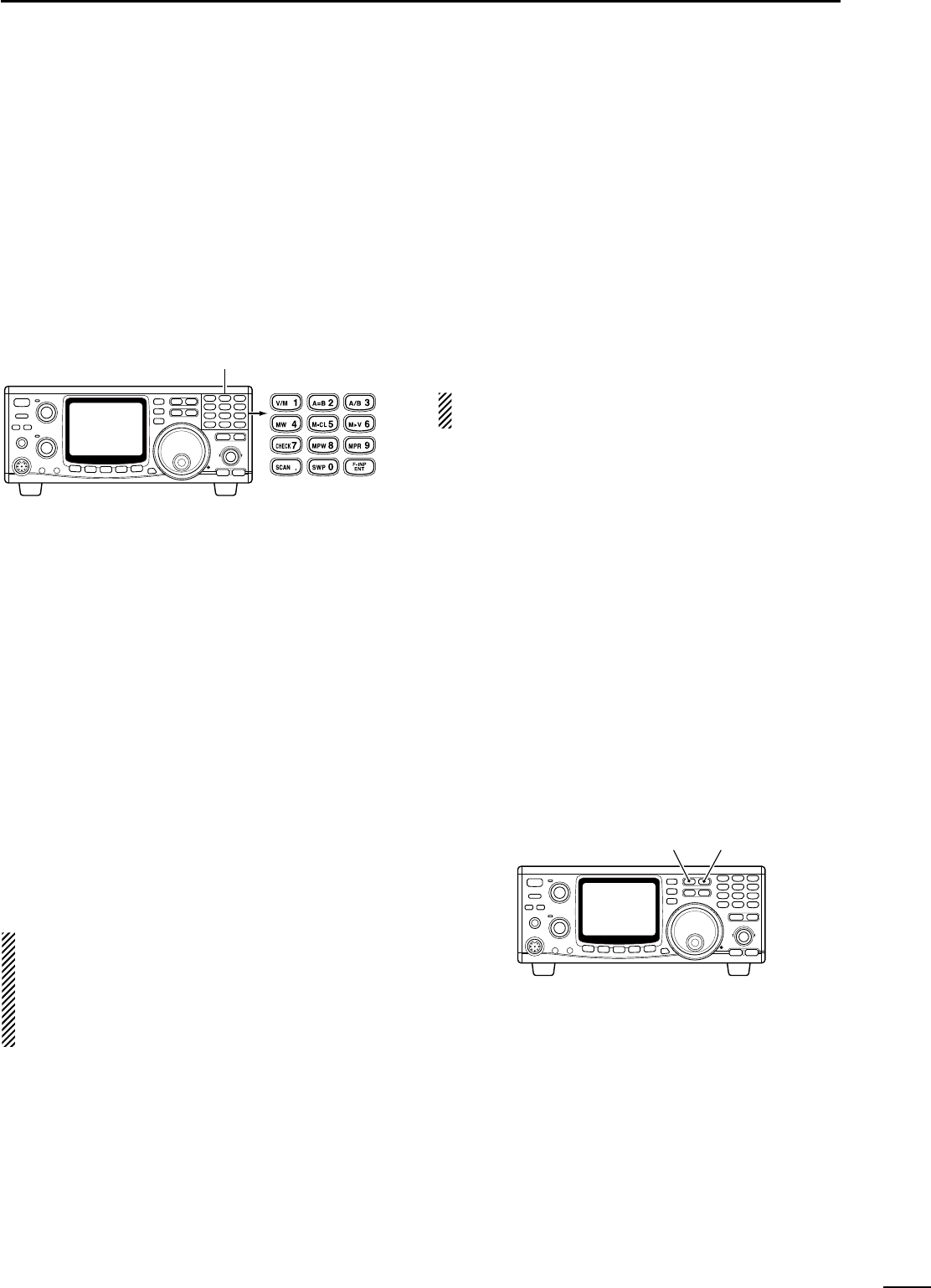
■Front panel
qPOWER SWITCH [POWER]
➥Push momentarily to turn power ON.
➥Push for 2 sec. to turn power OFF.
wTRANSMIT SWITCH [TRANSMIT]
Push to select transmitting or receiving.
eCOMPRESSION SWITCH [COMP] (p. 36)
Push to switch the speech compressor function ON
and OFF.
•The speech compressor increases average RF output
power, improving signal strength and readability in SSB.
rVOX SWITCH [VOX] (p. 33)
Push to switch the VOX function ON and OFF.
•The VOX (Voice-Operated Transmission) function tog-
gles between transmit and receive with your voice. This
function provides an opportunity to input log entries into
your computer, etc., while operating.
tHEADPHONE JACK [PHONES]
Accepts headphones.
•Output power: 5 mW with 8–16 Ωload.
•When headphones are connected, the internal speaker
or connected external speaker does not function.
•The MAIN and SUB band audio can be mixed or sepa-
rated when using stereo headphones according to set
mode settings. (p. 57)
yMICROPHONE CONNECTOR [MIC]
Accepts the supplied or optional microphone.
•See p. 81 for appropriate microphones.
•See p. 15 for microphone connector information.
uMIC GAIN CONTROL [MIC GAIN]
Adjusts microphone input gain.
✔
How to set the microphone gain.
Set the [MIC] control so that the [MAIN]/[SUB] indicator (ALC
indicator) some times lights brighter during normal voice
transmission in SSB mode.
iRF POWER CONTROL [RF PWR]
Continuously varies the RF output power from min-
imum to maximum.
144 MHz band 5–100 W
430(440) MHz band 5–75 W
1200 MHz band 1–10 W (optional UX-910)
RF PWR
IncreasesDecreases
MIC GAIN
Recommended level for
an Icom microphone
IncreasesDecreases
2
2
PANEL DESCRIPTION
q
o!0 !1 !2 !3
w
e
r
t
y
ui
oMAIN BAND INDICATOR [MAIN]
➥Lights green while the squelch is opened or a sig-
nal is received on the MAIN band; lights red while
transmitting on the MAIN band.
•While transmitting, the indicator also shows ALC con-
dition. Brightness increases more than usual when
the ALC function is activated.
➥Flashes when an off-frequency signal is received
and the FM center detector is activated. (p. 28)
!0 RF GAIN CONTROL/SQUELCH CONTROL
[RF/SQL] (outer control)
Adjusts the RF gain and squelch threshold level for
the MAIN band. The squelch removes noise output
from the speaker (closed condition) when no signal
is received.
•The squelch is particularly effective for FM. It is also
available for other modes.
•12 to 13 o’clock position is recommended for any setting
of the [RF/SQL] control.
•The squelch threshold position for SSB/CW mode can
be set from 12 or 13 o’clock position in SSB/CW set
mode. (p. 62)
•The control can be set as ‘Auto’(RF gain control in SSB
and CW; squelch control in FM) or squelch control (RF
gain is fixed at maximum) in set mode as follows. (p. 56)
•When setting as RF gain/squelch control
•When functioning as RF gain control
(Squelch is fixed open; SSB, CW only)
•When functioning as squelch control
(RF gain is fixed at maximum.)
!1 AF CONTROL [AF] (inner control)
Varies the audio output level from the speaker for
the MAIN band.
!2 SUB BAND INDICATOR [SUB]
Lights green while the squelch is opened or a signal
is received on the SUB band; lights red while trans-
mitting in satellite operation.
!3 RF GAIN CONTROL/SQUELCH CONTROL
[RF/SQL] (outer control)
Adjusts the RF gain and squelch threshold level for
the SUB band. The squelch removes noise output
from the speaker (closed condition) when no signal
is received.
AF RF/SQL
No audio output Max. audio output
Decreases Increases
Squelch is
open.
S-meter
squelch
S-meter squelch
threshold
Noise squelch
threshold
Shallow Deep
Noise squelch
Minimum RF gain
Adjustable
range
Maximum
RF gain
Recommended level
RF gain
adjustable
range (SSB,
CW modes)
Maximum
RF gain
S-meter
squelch
Noise squelch (FM mode)
Squelch is
open.
MODE
SSB, CW
FM
AUTO
RF GAIN
SQL
SQL
SET MODE SETTING
SQL
SQL
RF GAIN + SQL
RF GAIN + SQL
SQL
3
2
PANEL DESCRIPTION
4
2PANEL DESCRIPTION
■Front panel (continued)
!4 AF CONTROL [AF] (inner control)
Varies the audio output level from the speaker for
the SUB band.
!5 SET•MENU SWITCH [SET•MENU] (p. 55)
➥Push this switch then one of [FM],
[SSB/CW], [RIT], [SCAN], [NR], [TRANS-
MIT], [COMP], [VOX], [ATT], [SWP],
[MPW] or [SPCH] to enter the indepen-
dent item set mode.
➥Push for 1 sec. to enter the set mode for
commonly used item settings.
!6 ATTENUATOR•PRE-AMP SWITCH [ATT•P.AMP]
➥Push to switch the attenuator function
ON and OFF. (p. 29) Use this function to
protect from signal distortion from exces-
sively strong signals.
•The attenuation level is independently ad-
justable for 144 MHz or 430(440) MHz band
in the ATT set mode.The optional 1200 MHz
band attenuation level is fixed and is approx.
20 dB. (p. 65)
➥Push for 1 sec. to switch the connected
pre-amplifier ON and OFF, when an op-
tional pre-amplifier unit, AG-25, AG-35
and/or AG-1200, is connected. (p. 16)
DO NOT connect any equipment, such as an SWR
or power meter between the transceiver and pream-
plifier. In such case, the preamplifier may not acti-
vate properly.
!7 AUTO FREQUENCY CONTROL/NOISE
BLANKER•NOISE REDUCTION SWITCH
[AFC/NB•NR]
➥During FM/FM narrow mode operation,
push to switch the AFC (Automatic Fre-
quency Control) function ON and OFF.
(p. 28)
•Automatically tunes the operating frequency,
when an off-frequency signal is received, in
100 kHz steps. This function also follows the
signal even if the frequency is shifted.
➥During SSB or CW mode operation, push
to switch the noise blanker function ON
and OFF. (p. 30)
•Reduces pulse-type noise, such as ignition
noise from a vehicle.
➥Push for 1 sec. to switch the noise reduc-
tion function ON and OFF when an op-
tional DSP unit, UT-106, is installed.
(p. 31)
•Reduces unwanted noise and pulls out the
desired signal only for clear readability.
For 1 sec.
For 1 sec.
For 1 sec.
!4 !5 !6 !7 !8 !9 @0 @1 @2 @3
5
2
PANEL DESCRIPTION
!8 AUTO GAIN CONTROL•AUTO NOTCH FILTER
SWITCH [AGC•ANF]
➥Push to switch the time constant of the
automatic gain control to SLOW and
FAST for the MAIN band.* (p. 28)
•SLOW selection (“FAGC”disappears) during
SSB (USB or LSB) operation, FAST selection
(“FAGC”appears) during CW, data operation
and while tuning with fast tuning dial rotation
are recommended.
*The AGC time constant can be selected on the
MAIN band only. FAST selection is fixed on the
SUB band.
➥Push for 1 sec. to switch the automatic
notch filter function ON and OFF when
the optional DSP unit, UT-106, is in-
stalled. (p. 31)
•Reduces interference signals such as beat,
RTTY or CW signals and the notch frequency
automatically follows the interfering signal.
!9 kHz/MHz•TUNING STEP SELECTION SWITCH
[kHz/MHz] (p. 22)
➥Push to select tuning step for the tuning
dial or scanning from 1 kHz, 1 MHz step
and regular tuning step* in sequence
•“ZZ”appears above the 1 kHz or 1 MHz digit
when 1 kHz or 1 MHz tuning step is selected,
respectively.
*The regular tuning step is selected for each
operating mode as follows.
➥Push for 1 sec. to enter the regular tun-
ing step selection mode.
•The tuning step can be selected for each op-
erating mode independently.
•SSB/CW mode: 1, 10, 50 and 100 Hz step;
FM mode: 0.1, 5, 6.25, 10, 12.5, 20, 25 and
100 kHz step can be selected by rotating the
tuning dial.
@0 SPEECH•LOCK SWITCH [SPCH•LOCK]
➥Announces the receiving signal strength
and/or selected readout frequency when
the optional UT-102 is installed. (pgs. 69,
71)
➥Push for 1 sec. to switch the tuning dial
lock function ON and OFF to prevent ac-
cidental setting changes. (p. 25)
@1 TUNING DIAL
Changes the displayed frequency, selects set mode
items, etc.
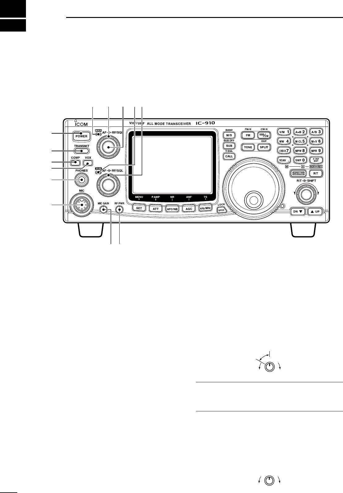
@2 BRAKE ADJUSTMENT SCREW
Adjust the tension of the tuning dial.
•Rotate clockwise to increase the tension; counterclock-
wise to decrease the tension.
@3 MEMORY CHANNEL UP/DOWN SWITCHES
[YYUP]/[DOWN ZZ](p. 40)
➥Push [YUP] to change the memory
channel up; push [DOWN Z] to change
the memory channel down.
•Memory channel changes continuously while
holding either switch.
•Memory channels can be selected both in
VFO and memory modes.
For 1 sec.
or
or
Brake adjustment screw
For 1 sec.
For 1 sec.
For 1 sec.
6
2PANEL DESCRIPTION
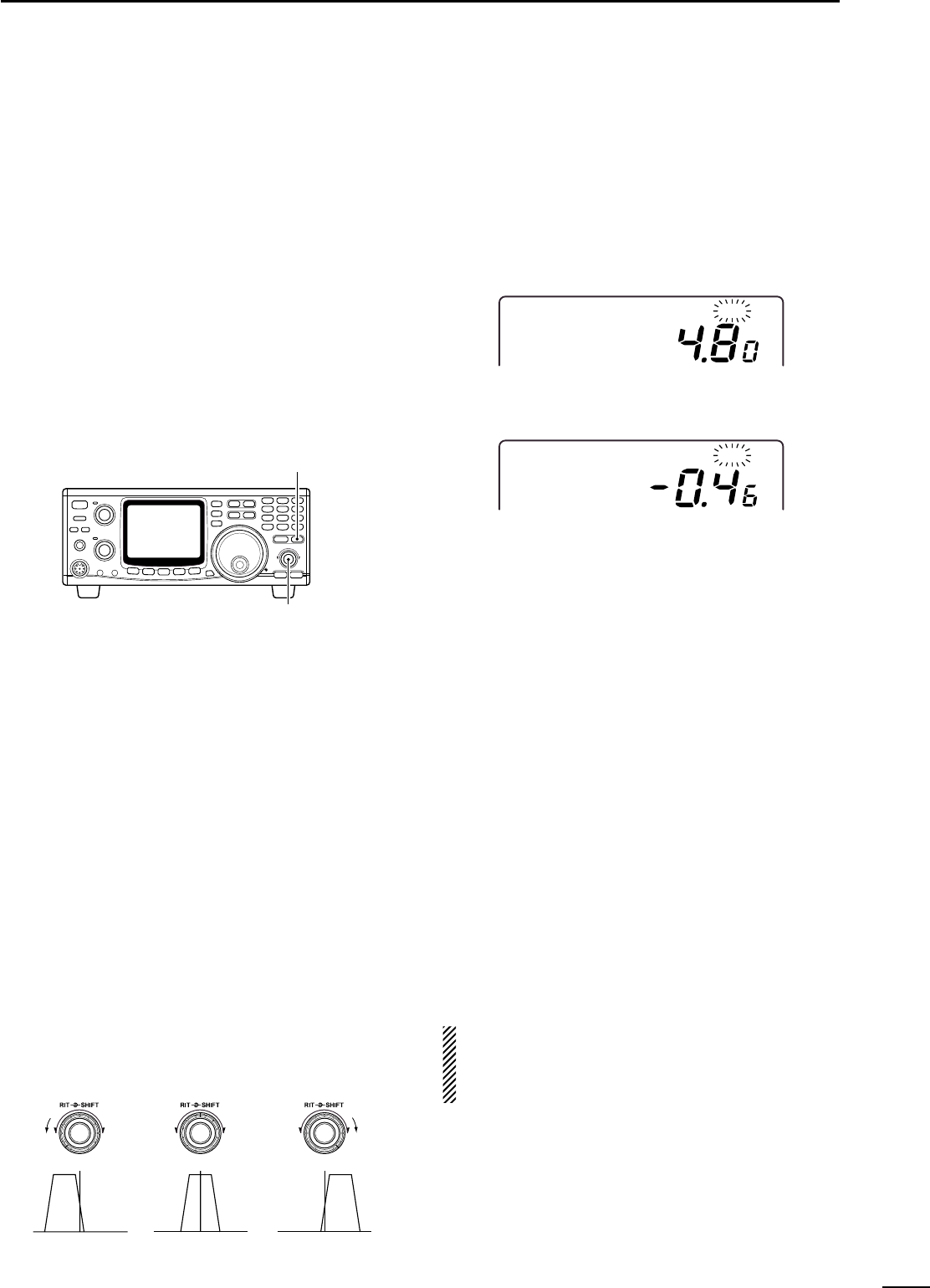
@4 RIT CONTROL [RIT] (p. 27)
Shifts the receive frequency without changing the
transmit frequency for the MAIN band only while the
RIT function is activated.
•SSB/CW mode : ±1.0 kHz* in 10 Hz step
•FM mode : ±5.0 kHz* in 50 Hz step
*For 1200 MHz band; ±2.0 kHz and ±10.0 kHz, respec-
tively when the optional UX-910 is installed.
•By using the Sub dial function, the RIT control can be
used as the MAIN/SUB tuning dial or the SUB band IF
shift control. See page 24 for details.
@5 IF SHIFT CONTROL [SHIFT]
Shifts the center frequency of the receiver’s IF pass-
band within 1.2 kHz range.
•By using the Sub dial function, the IF shift control can be
used as the MAIN/SUB tuning dial or the SUB band IF
shift control. See page 24 for details.
✔
What is the Sub dial function?
The [RIT] and [SHIFT] controls are used for RIT and IF shift
controls for the MAIN band by default. However, the Sub dial
function assigns these controls as the MAIN/SUB tuning dial
or the SUB band IF shift control. (p. 24, 68)
@6 SATELLITE SWITCH [SATELLITE]
➥Push to enter satellite mode (RX on
MAIN, TX on SUB band). Push again to
return to the condition before entering
into the satellite mode.
➥Push to enter satellite mode using the
current operating frequencies when
pushing for 1 sec.
•To change the normal and reverse satellite
operations, push [F-INP/ENT] for 1 sec.
@7 RIT SWITCH [RIT] (p. 27)
➥Push to switch the RIT control activity ON
and OFF.
•“RIT”indicator appears when the RIT func-
tion is in use.
➥Push for 1 sec. to switch the Sub dial
function ON and OFF.
•“RIT”indicator flashes and the [RIT] and
[SHIFT] controllers acts as the controllers
specified in the RIT/SHIFT set mode. (p. 68)
@8 KEYPAD
Numeral and other function keys for tuning and ac-
tivating functions.
See the table at right.
For 1 sec.
For 1 sec.
For 1 sec.
RIT S
H
IFT RIT S
H
IFT RIT S
H
IFT
Center positionMax. counter-
clockwise position Max. clockwise
position
■Front panel (continued)
@4
@5
@6
@8
@7
7
2
PANEL DESCRIPTION
•Enters numeral “1”when entering an operating
frequency. (p. 23)
•Switches between VFO and memory mode.
(p. 40)
Enters numeral “2”when entering an operating
frequency. (p. 23)
•Enters numeral “3”when entering an operating
frequency. (p. 23)
•Switches between VFO A and B during VFO
mode operation. (p. 21)
Enters numeral “4”when entering an operating
frequency. (p. 23)
Enters numeral “5”when entering an operating
frequency. (p. 23)
Enters numeral “6”when entering an operating
frequency. (p. 23)
Enters numeral “7”when entering an operating
frequency. (p. 23)
•Enters numeral “8”when entering an operating
frequency. (p. 23)
•Stores the displayed operating conditions into
MEMO PAD channel (p. 44)
•Enters numeral “9”when entering an operating
frequency. (p. 23)
•Re-calls the contents in the MEMO PAD channel.
(p. 44)
•Enters decimal point “.”for entering below the
“MHz“ digits when entering an operating fre-
quency.
•Starts and cancels scanning function. (p. 46)
•Turns OFF the SUB band frequency indication
during satellite operation. In this case, only the
MAIN band frequency can be tuned by rotating
the tuning dial. (p. 49)
•Enters numeral “0”when entering an operating
frequency. (p. 23)
•Switches sweep function for the bandscope ON
and OFF. (p. 29)
•Turns OFF the MAIN band frequency indication
during satellite operation. In this case, only the
SUB band frequency can be tuned by rotating
the tuning dial. (p. 49)
Enables operating frequency entering from the
keypad. See page 23 for details.
Equalizes the condition of the VFO A and B.
(p. 21)
Shows 10 Hz and 1 Hz digits of operating fre-
quency on both the MAIN and SUB bands while
pushing and holding. (p. 22)
Stores the set conditions into a memory channel.
(p. 41)
Clears stored contents of memory channel to be
a blank channel. (p. 43)
Transfers the contents of a memory channel into
either the VFO A or B. (p. 42)
Opens squelch for monitoring the operating or
transmit frequency, and the frequency indication
automatically changes to transmit frequency in the
case of duplex or split operation. (p. 34)
Starts and cancels tone scan when the repeater
tone or tone squelch is activated in FM (narrow)
operation. (p. 47)
Used to change memory channel during memory
mode operation by rotating the tuning dial while
pushing and holding. (p. 40)
Switch Switch action when pushed Switch action when pushed for 1 sec.
8
2PANEL DESCRIPTION
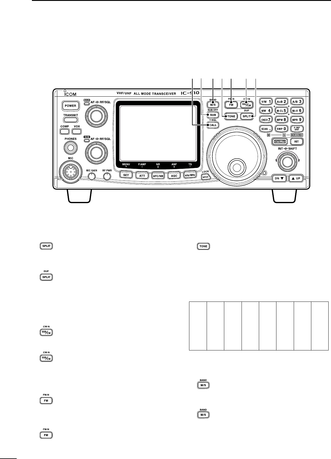
@9 SPLIT•DUPLEX SWITCH [SPLIT•DUP]
➥Push to turn the split function, with the
VFO A and B, ON and OFF. (p. 37)
•The split operation is not available for the
SUB band.
➥Push for 1 sec. to select the duplex (re-
peater) direction or to turn the function
OFF. (p. 34)
•The duplex operation is not available for the
SUB band.
#0 SSB/CW•CW-NARROW SWITCH
[SSB/CW•CW-N]
➥Push to switch the operating mode be-
tween SSB and CW. (p. 23)
➥Push for 1 sec. to switch the operating
mode between USB and LSB or between
CW and CW narrow during SSB or CW
mode, respectively.
#1 FM•FM-NARROW SWITCH [FM•FM-N] (p. 23)
➥Push to switch the operating mode be-
tween FM and FM repeater mode.
•The duplex operation can be made in MAIN
band only, it cannot be operated in SUB
band.
➥Push for 1 sec. to switch the operating
mode between FM and FM-N (FM nar-
row).
•The FM-N mode cannot be selected in
1200 MHz band operation.
#2 TONE SWITCH [TONE]
➥Push to turn the tone encoder function
ON and OFF in FM mode. (p. 31; except
for European version)
•“T”indicator appears in the display when the
tone encoder is activated.
➥Push to transmit a 1750 Hz repeater tone
in FM mode for European version.
Available repeater tones (Unit: Hz)
#3 MAIN/SUB CHANGE•BAND SWITCH
[M/S•BAND]
➥Push to replace the MAIN band’s fre-
quency and mode with the SUB band’s.
(p. 19)
➥Push for 1 sec. to change the operating
band during single band operation or
when the optional band unit, UX-910, is
installed. (p. 20)
For 1 sec.
For 1 sec.
For 1 sec.
For 1 sec.
#5 #4 #3 #2 #1 #0 @9
67.0
69.3
71.9
74.4
77.0
79.7
82.5
085.4
088.5
091.5
094.8
097.4
100.0
103.5
107.2
110.9
114.8
118.8
123.0
127.3
131.8
136.5
141.3
146.2
151.4
156.7
159.8
162.2
165.5
167.9
171.3
173.8
177.3
179.9
183.5
186.2
189.9
192.8
196.6
199.5
203.5
206.5
210.7
218.1
225.7
229.1
233.6
241.8
250.3
254.1
■Front panel (continued)

9
2
PANEL DESCRIPTION
#4 SUB•SUB OFF SWITCH [SUB•SUB OFF]
➥Push to enable the SUB band control
from the tuning dial, keypad, etc. (p. 19)
•“SUB”indicator appears.
➥Push for 1 sec. to turn the SUB band
readout indication ON and OFF. (p. 24)
#5 CALL•TONE SQUELCH SWITCH [CALL•T-SQL]
➥Push to select the call channel of the op-
erating band.The call channel can be se-
lected from both the VFO and memory
mode operation. (p. 43)
➥Push for 1 sec. to turn the tone squelch
function ON and OFF during FM mode
operation. (p. 30)
•“T-SQL”indicator appears when the tone
squelch is activated.
For 1 sec.
For 1 sec.
10
2PANEL DESCRIPTION
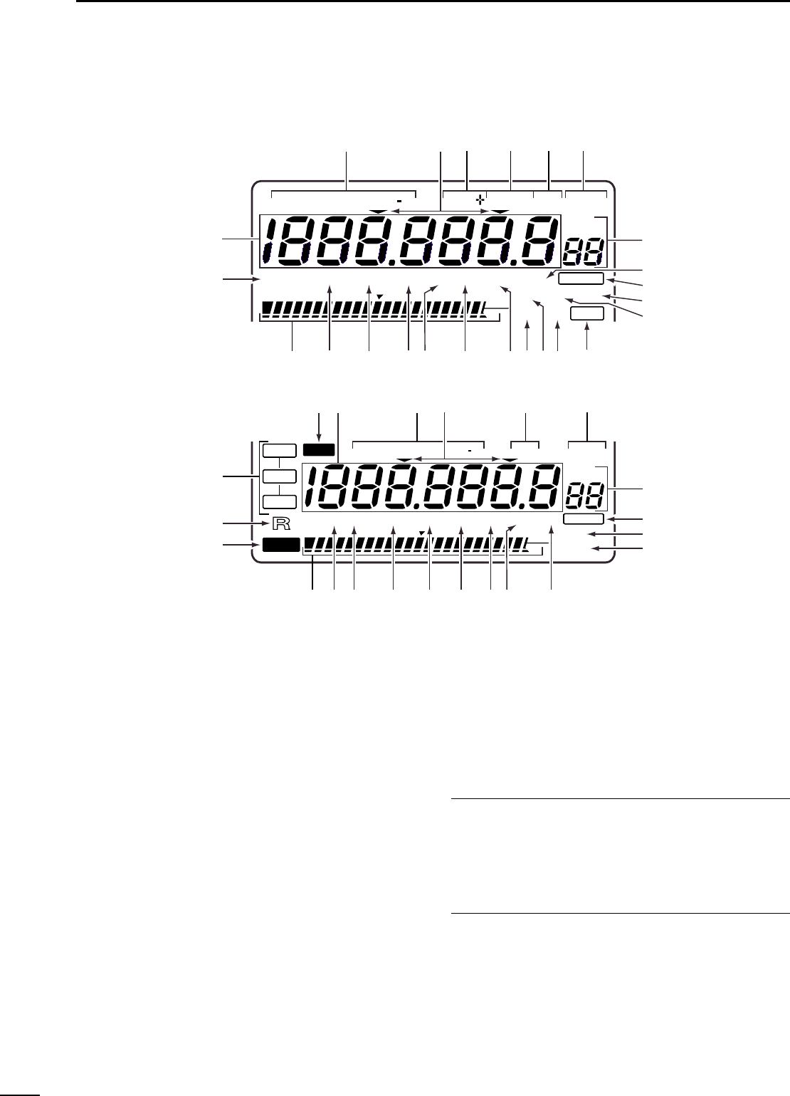
qFREQUENCY READOUTS (p. 22)
Shows the operating frequency.
•Setting item name is indicated during set mode. (p. 55)
wMODE INDICATOR (p. 23)
Shows the selected operation mode.
eTUNING STEP INDICATOR (p. 22)
Appears when the 1 kHz or 1 MHz tuning step is se-
lected.
rDUPLEX INDICATOR (p. 34)
Either “DUP–” or “DUP+”appears during duplex (re-
peater) operation.
tSPLIT INDICATOR (p. 37)
Appears during split operation.
yRIT INDICATOR (p. 27)
➥Appears while the RIT function is activated.
➥Flashes while the SUB dial function is activated.
uVFO INDICATOR (p. 21)
Either VFO A or VFO B appears during VFO opera-
tion.
iMEMORY MODE INDICATORS/MEMORY
CHANNEL NUMBER READOUTS (p. 40)
The memory mode indicator appears during mem-
ory mode operation and the memory channel num-
ber readout shows the selected memory channel
number during both the memory and VFO mode op-
eration.
✔
Memory channel number readout
In addition to the memory channel number indication, the
memory channel number readout indicates 10 Hz and 1 Hz
digits of operating frequency while rotating the tuning dial in
SSB or CW mode with 10 or 1 Hz tuning step. After 2 sec.
from tuning dial operation, the readout indicates the memory
channel number.
oAUTO NOTCH FILTER INDICATOR (p. 31)
Appears when the optional DSP unit, UT-106, is in-
stalled, and the ANF (Automatic Notch Filter) func-
tion is activated.
!0 BLANK INDICATOR (p. 42)
Appears when the selected memory channel has
not been programmed or has been cleared.
VF
O
A
VF
O
B
M
E
MO
R
ITCW N
L
SB
U
SB
N
F
M
S
U
B
NOR
S
A
T
L
RE
V
L
OCK
T-SQSQ
L
S1357920 40 60dB
ATT P.AMP.AMP AFCAFCNBNB FAGCAGC NR ANF
BLBL
A
NKNK
S
W
P
S
C
A
N
OVEROVER
MEMO
F
M
N
USBUSBLSB
C
W
N
RITRIT
SPLITSPLIT VFO A
VFO B
S
E
T
BL
AN
K
T-SQ
L
A
TT P.AMP AFCN
BF
AGCAGC
N
R
ANFANF
9600
COMPMP
S
W
P
60dB
V
O
X
S
C
A
N
OVEROVER
S13 5 7920 40
DUP
q
q
w
w
e
e
rty
y
u
u
i
i
o
o
!0
!0
!1
!2
!3!4
!5
!5
!6
!6
!7
!7
!8
!8
!9
!9
@0
@0
@1
@1
@2
@2
@3
@3
@5
@6
@7
@8
@4
@4
■Function display

11
2
PANEL DESCRIPTION
!1 DATA TRANSMISSION SPEED INDICATOR
(p. 52)
Appears when 9600 bps speed is selected for
packet transmission.
!2 SPEECH COMPRESSOR INDICATOR (p. 36)
Appears when the speech compressor is activated.
!3 SET INDICATOR (p. 55)
Appears when [SET] is pushed.
Disappears after any switch is pushed.
!4 VOX INDICATOR (p. 33)
Appears when the VOX function is activated.
!5 SWEEP INDICATOR (p. 29)
Flashes while the simple bandscope function is ac-
tivated.
!6 SCAN INDICATOR (p. 46)
Flashes while scanning.
!7 NOISE REDUCTION INDICATOR (p. 31)
Appears when the optional DSP unit, UT-106, is in-
stalled and the noise reduction is activated.
!8 AGC TIME CONSTANT INDICATOR (p. 28)
Appears when the FAST AGC time constant is se-
lected; disappears when the SLOW AGC time con-
stant is selected.
!9 NOISE BLANKER INDICATOR (p. 30)
Appears when the noise blanker function is acti-
vated.
@0 AUTO FREQUENCY CONTROL INDICATOR
(p. 28)
Appears when the AFC (Automatic Frequency Con-
trol) function is activated.
@1 PRE-AMP INDICATOR (p. 16)
Appears when the optional pre-amplifier unit,
AG-25, AG-35 and/or AG-1200, is connected and
the pre-amplifier function is activated.
@2 ATTENUATOR INDICATOR (p. 29)
Appears when the attenuator is activated.
@3 MULTI-FUNCTION BAR METER
➥Shows the receiving signal strength as an S-
meter while receiving. Peak hold function is avail-
able and can be switched ON and OFF in regular
set mode. (pgs. 26, 56)
➥Shows the relative transmit output power level as
an RF power indicator during transmit. (p. 32)
➥Shows signal availability in the sweeping band,
and the “▼”indicator indicates the center of the
sweeping frequency band.
@4 TONE SQUELCH INDICATOR (pgs. 30, 34)
“T”appears when the tone encoder function is acti-
vated; “T-SQL”appears when the tone squelch func-
tion is activated.
@5 SUB INDICATOR (p. 19)
Appears when the SUB band access is enabled.
@6 SATELLITE INDICATOR (p. 49)
Appears while satellite operation mode is selected.
•- : Satellite operation with normal mode
is selected.
•- : Satellite operation with reverse mode
is selected.
@7 REMOTE INDICATOR (p. 78)
Appears when the transceiver is controlled remotely
via the optional CI-V level converter, CT-17.
@8 LOCK INDICATOR (p. 25)
Appears when the dial lock function is activated.
REV
SATL
NOR
SATL
12
2PANEL DESCRIPTION
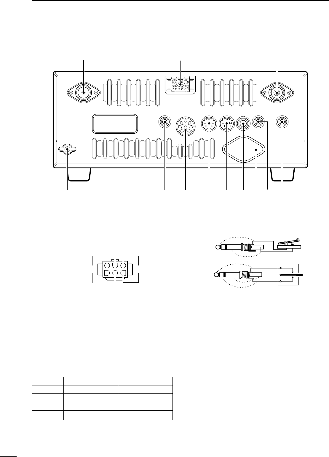
■Rear panel
q430(440) MHz ANTENNA CONNECTOR (p. 15)
Accepts a 50 Ωantenna with a type-N connector.
wDC POWER SOCKET [DC 13.8V] (p. 17)
Accepts 13.8 V DC through the supplied DC power
cable (OPC-657A).
e144 MHz ANTENNA CONNECTOR (p. 15)
Accept a 50 Ωantenna with a PL-259 connector.
rSUB BAND EXTERNAL SPEAKER JACK
[SP (SUB)]
tMAIN BAND EXTERNAL SPEAKER JACK
[SP (MAIN)] (p. 16)
Accepts a 4–8 Ωspeaker.
By connecting an external speaker for each or both
jacks, the audio for both the MAIN and SUB bands
is output as follows.
y1200 MHz ANTENNA CONNECTOR (p. 15)
Available when the optional 1200 MHz band unit is
installed. Accepts a 50 Ωantenna with a type-N
connector.
uKEY JACK [KEY] (p. 15)
Accepts a paddle, a straight key or external elec-
tronic keyer with 1⁄8inch standard plug.
iSUB BAND DATA SOCKET [DATA (SUB)]
oMAIN BAND DATA SOCKET [DATA (MAIN)]
(p. 13)
6-pin mini plug DIN jack to connect a TNC, etc. for
high speed data communications.
Simultaneous data communications are provided by
equipping independent data sockets for both MAIN
and SUB bands.
!0 ACCESSORY SOCKET [ACC(1)]
Enables connection of external equipment such as
a TNC for data communications, etc.
•See the right table for socket information.
!1 CI-V REMOTE CONTROL JACK [REMOTE]
(p. 78)
Designed for use with a personal computer via the
optional CT-17 for remote control of transceiver
functions.
!2 GROUND TERMINAL [GND] (p 14)
Connect this terminal to a ground to prevent electri-
cal shocks and other problems.
(dot)
(com)
(dash)
(+)
(_)
Rear panel
view +_
o
!2
we
r
t
y
u
i
q
!0
!1
MAIN AF SUB AF
No Int. SP Int. SP
SP (MAIN) Ext. SP Ext. SP
SP (SUB) Int. SP Ext. SP
Both Ext. SP (MAIN) Ext. SP (SUB)
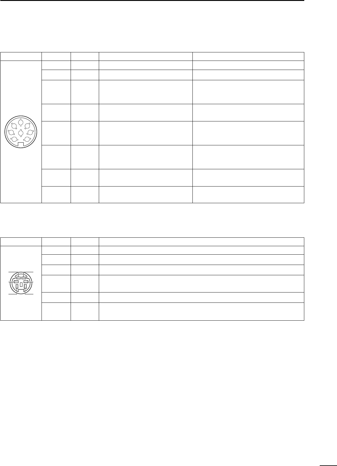
DATA Socket Pin No. Pin Name Description
ACC(1) Socket Pin No. Pin Name Description Specification
13
2
PANEL DESCRIPTION
DACC SOCKETS
DDATA SOCKETS
1
2
3
4
5
6
7
8
NC
GND
SEND
MOD
AF
SQLS
13.8 V
ALC
No connection.
Connect to ground.
Input terminal to transmit the trans-
ceiver in relation to the external equip-
ment. (Grounded: transmits)
Input terminal for the modulation cir-
cuit.
Output terminal for AF signals from
the AF detector circuit. Output level is
fixed, regardless of [AF] control.
Output terminal for squelch condition
(Open/Close). Outputs grounded level
signal when squelch is opened.
Output terminal for 13.8 V DC, in rela-
tion to the [POWER].
Input terminal for ALC control.
Transmit voltage : –0.5 to +0.8 V
Output current : Less than 20 mA
Input current (Tx) : Less than 200 mA
Output impedance : 10 kΩ
Input level : 100 mV rms
Output impedance : 4.7 kΩ
Output level : 100–300 mV rms
Squelch open : Less than 0.3 V/5 mA
Squelch close : More than 6.0 V/100 µA
Output current : Less than 1 A
Input impedance : More than 10 kΩ
Control voltage : –4 to 0 V
1
2
3
45
67
8
1
2
3
4
5
6
DATA IN
GND
PTTP
DATA
OUT
AF OUT
SQL
Input terminal for data (common for both 1200 and 9600 bps)
Ground line for the DATA IN, DATA OUT and AF OUT.
Transmits when this terminal is grounded.
Received data output terminal for 9600 bps operation.
Received data output terminal for 1200 bps operation.
Output terminal for squelch condition (Open/Close). Outputs grounded level signal
when squelch is opened, +8 V level signal when squelch is closed.
qw
e
y
t
r
3
14
INSTALLATION AND CONNECTIONS
■Unpacking
After unpacking, immediately report any damage to the
delivering carrier or dealer. Keep the shipping cartons.
For a description and a diagram of accessory equip-
ment included with the IC-910H, see ‘Supplied acces-
sories’on p. 1 of this manual.
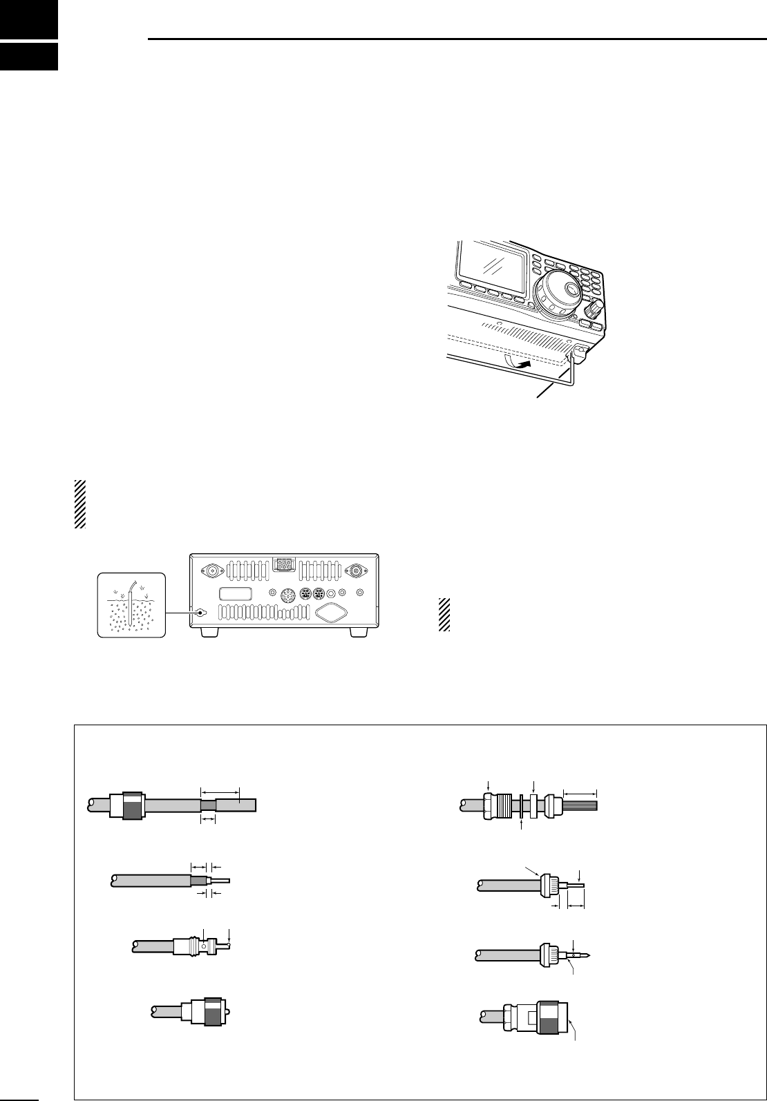
■Grounding
To prevent electrical shock, television interference
(TVI), broadcast interference (BCI) and other prob-
lems, ground the transceiver through the GROUND
terminal on the rear panel.
For best results, connect a heavy gauge wire or strap
to a long earth-sunk copper rod. Make the distance be-
tween the [GND] terminal and ground as short as pos-
sible.
RWARNING: NEVER connect the [GND]
terminal to a gas or electric pipe, since the connec-
tion could cause an explosion or electric shock.
■Selecting a location
Select a location for the transceiver that allows ade-
quate air circulation, free from extreme heat, cold, or
vibrations, and away from TV sets, TV antenna ele-
ments, radios and other electro-magnetic sources.
The base of the trans-
ceiver has an ad-
justable stand for desk-
top use. Set the stand
to depending on your
operating conditions.
■Antenna connection
For radio communications, the antenna is of critical im-
portance, along with output power and sensitivity. Se-
lect antenna(s), such as a well-matched 50 Ωantenna,
and feedline. 1.5:1 or better of Voltage Standing Wave
Ratio (VSWR) is recommended for your desired band.
Of course, the transmission line should be a coaxial
cable.
CAUTION: Protect your transceiver from lightning
by using a lightning arrestor.
PL-259 CONNECTOR INSTALLATION EXAMPLE TYPE-N CONNECTOR INSTALLATION EXAMPLE
30 mm ≈9⁄8in 10 mm ≈3⁄8in 1–2 mm ≈1⁄16 in
Slide the coupling ring
down. Strip the cable
jacket and soft solder.
Slide the connector body
on and solder it.
Screw the coupling ring
onto the connector body.
Strip the cable as shown at
left. Soft solder the center
conductor.
q
w
e
r
Slide the nut, rubber
gasket and clamp over the
coaxial cable, then cut the
end of the cable evenly.
Strip the cable and fold the
braid back over the clamp.
Soft solder the center
conductor. Install the
center conductor pin and
solder it.
Carefully slide the plug
body into place aligning the
center conductor pin on the
cable. Tighten the nut onto
the plug body.
q
w
e
r
15 mm
3 mm 6 mm
30 mm
10 mm (soft solder)
10 mm
1–2 mm
solder solder
Soft
solder
Coupling ring
No space
Solder hole
Be sure the center conductor is
the same height as the plug body.
Clamp Center
conductor
Washer
Nut Rubber gasket
DC POWER SUPPLY (p. 17)
[430(440)MHz ANT]
(p. 14)
[1200MHz ANT] (p. 14)
[144MHz ANT] (p. 14)
[KEY] jack (p. 38)
GROUND (p. 14)
Required for optional
UX-910 operation.
+_
13.8 V DC
More than 25 A
(dot)
(com)
(dash)
+
_
15
3
INSTALLATION AND CONNECTIONS
SM-20 DESKTOP
MICROPHONE (optional) MICROPHONE CONNECTOR (Front panel view)
Input impedance:
8–16 Ω
Audio output power:
5 mW with 8 Ω load
Output power may differ
according to the headphone
HM-12 HAND
MICROPHONE
HEADPHONES
q MIC (Microphone input)
w +8V (Max. 8 V DC 10 mA)
e MIC U/D (Frequency up/down)
r SQL S (Squelch switch)
t PTT
y GND (PTT ground)
u GND (Microphone ground)
i AF OUT (varies with [AF])
CAUTION: DO NOT short pin 2 to ground as this can damage the
internal 8 V regulator. DC voltage is applied to pin 1 for microphone
operation. Take care when using a non-Icom microphone.
q
w
e
r
t
y
u
i
■Required connections
•Front panel
•Rear panel
16
3INSTALLATION AND CONNECTIONS
MB-23 CARRYING HANDLE
PREAMP (p. 59)
(144 MHz/430(440) MHz/1200 MHz) EXTERNAL SPEAKER
(MAIN/SUB) (p. 12)
CT-17
144 MHz : AG-25
430(440) MHz : AG-35
1200 MHz : AG-1200
External all-weather, mast
mounting preamplifiers are
available.
MAIN
MAIN
144 MHz430(440) MHz 1200 MHz (optional)
SUB
SUB
sp-7
icom
Use 4–8 Ω speakers.
[REMOTE] (p. 78)
Used for computer control and transceive
operation.
Used for external
equipment control.
ACC SOCKETS
(pgs. 13, 52) DATA SOCKETS
(MAIN/SUB) (pgs. 13, 52)
CAUTION: NEVER
connect equipment
(i.e. power, SWR meter)
between transceiver
and preamplifier.
■Advanced connections
•Front panel
•Rear panel
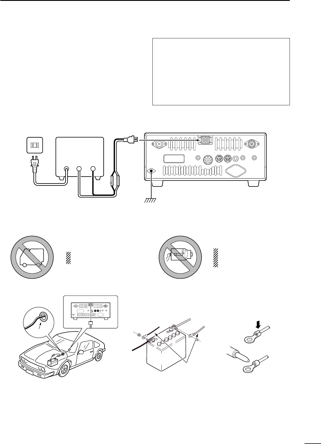
AC outlet
AC cable
13.8 V DC 25 A
A DC power supply
Black
_
Red
+
IC-910H
Supplied DC
power cable
17
3
INSTALLATION AND CONNECTIONS
24V Ciga
IC-910H
12 V
battery Supplied
DC power cable
+ red
_ black
Crimp
Solder
Grommet
CONNECTING A VEHICLE BATTERY
CONNECTING A DC POWER SUPPLY
■Power supply connections
Use an optional DC power supply with a 25 A capacity
and above when operating the transceiver with AC
power. Refer to the diagrams below.
CAUTION: Before connecting the DC power
cable, check the following important items. Make
sure:
•The [POWER] switch is OFF.
•Output voltage of the power source is 12–15 V
when you use a non-Icom power supply.
•DC power cable polarity is correct.
Red : positive +terminal
Black : negative _terminal
NEVER connect to
a 24 V battery.
NEVER use the cig-
arette lighter socket as
a power source.
NOTE: Use terminals for
the cable connections.
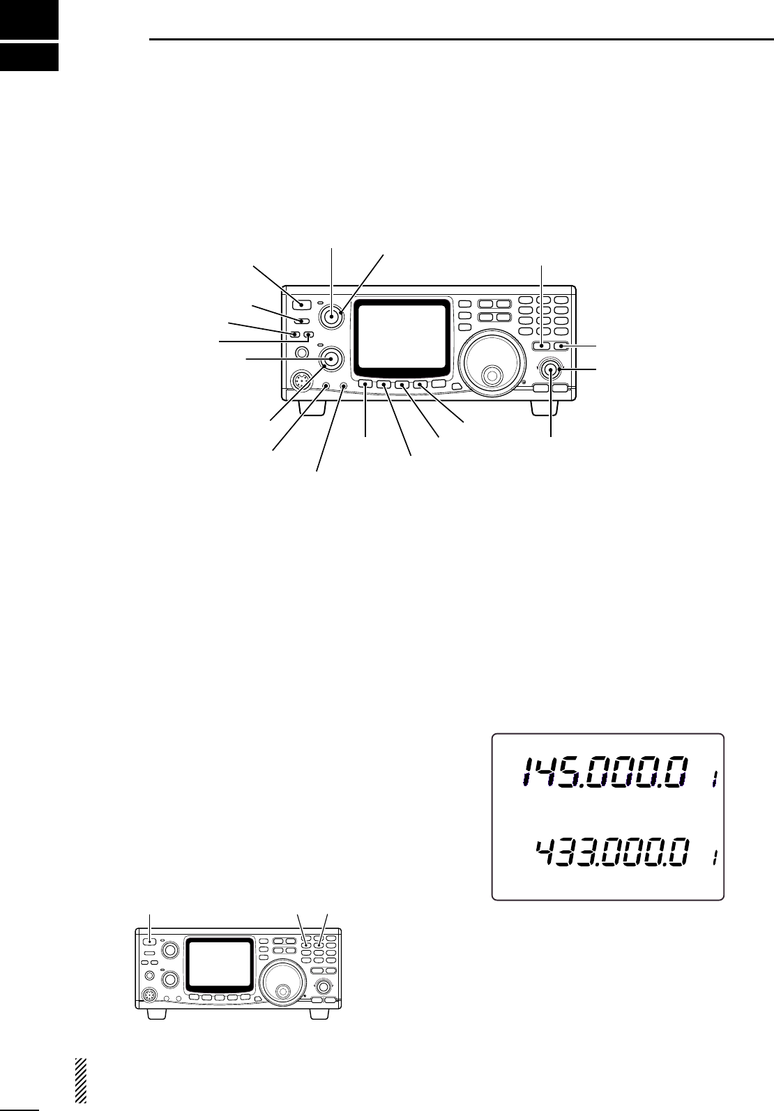
■Initial settings
After resetting the transceiver, set controls and
switches as shown in the figure below.
Turn power ON, then check the display. If any of the fol-
lowing indicators appear, turn them OFF as follows:
•Quick tuning step indicator “▼”: Push [kHz/MHz].
•RIT indicator “RIT”: Push [RIT].
•Split indicator “SPLIT”: Push [SPLIT].
CCW : Max. counterclockwise
4
18
BASIC OPERATION
■When first applying power (CPU resetting)
Before first applying power, make sure all connections
required for your system are complete by referring to
Chapter 3. Then, reset the transceiver using the fol-
lowing procedure.
qMake sure the transceiver power is OFF.
wWhile pushing [MW 4] and [M-CL 5], push
[POWER] to turn power ON.
•The internal CPU is reset.
•The transceiver displays its initial VFO frequencies when
resetting is complete.
Resetting CLEARS all programmed contents in
memory channels and returns programmed values
in set mode to default values.
[POWER] [MW 4] [M-CL 5]
F
M
VFO A
VFVF
O
A
F
M
S135792020 4040 60dB60dB
60dB
S13 5 7920 40
[TRANSMIT]: OFF
[COMP]: OFF
[VOX]: OFF
[AF] (SUB band):
CCW
[RF/SQL]: (SUB band)
12 o’clock
[MIC]: CCW [SET]: OFF
[ATT(P.AMP)]: OFF
[RF PWR]: CCW
[AFC/NB]: OFF
[AGC]: OFF
[RIT]: 12 o’clock
[SHIFT]: 12 o’clock
[RIT]: OFF
[POWER]: OFF
[AF] (MAIN band):
CCW [RF/SQL] (MAIN band):
12 o’clock [SATELLITE]: OFF
19
4
BASIC OPERATION
■MAIN and SUB bands
The IC-910H has dual bands: 144 MHz and 430(440)
MHz. These bands can be assigned to the MAIN and
SUB bands for operating convenience.
Each MAIN and SUB bands have independent fea-
tures.
The MAIN band is the operation for both transmit and
receive, and is displayed in the upper area of the func-
tion display.The SUB band is the operation for only re-
ceive, and is displayed in the lower area of the function
display.
Simultaneous receive on both the MAIN and SUB
bands is possible, however the transmission can
only be transmitted on the MAIN band— not on the
SUB band.
In the case of satellite operation mode, the SUB
band is used for the transmission band.
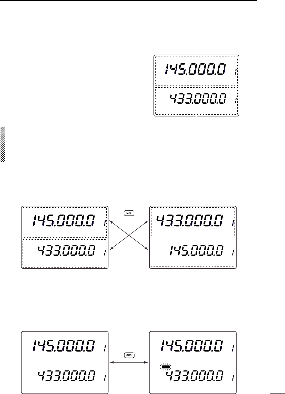
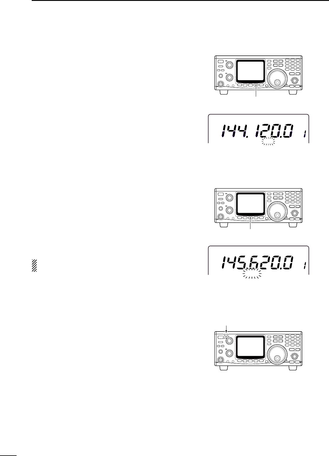
◊Exchanging the MAIN and SUB bands
The function display shows both the MAIN and SUB
band frequencies and both bands can receive signals
simultaneously.
Assign 144 MHz or 430(440) MHz band, whichever
band you want to transmit or be called on, as the MAIN
band.
➥Push [M/S] to exchange the MAIN and SUB bands.
F
M
VFO A
VFVF
O
A
F
M
S1357920 40 60dB60dB
60dB
S13 5 7920 40
MAIN band display
SUB band display
F
M
VFO A
VFVF
O
A
F
M
S 1 3 5792020 4040 60dB60dB
60dB
S13 5 7920 40
F
M
VFO A
VFVF
O
A
F
M
S 1 3 5792020 4040 60dB60dB
60dB
S13 5 7920 40
MAIN band display
SUB band display
F
M
VFO A
VFVF
O
A
F
M
S 1 3 5792020 4040 60dB60dB
60dB
S13 5 7920 40
F
M
VFO A
VFVF
O
A
F
M
S 1 3 5792020 4040 60dB60dB
60dB
S13 5 7920 40
S
U
B
◊Accessing the SUB band
Normally, any operations, such as tuning, operating
mode selection, memory channel selection and pro-
gramming, etc., are performed on the MAIN band.
However, these operations can be performed on the
SUB band by using the SUB band access capability.
➥Push [SUB] to switch the SUB band access capa-
bility ON and OFF.
•“SUB”indicator appears while the SUB band access ca-
pability is activated.
•Even during SUB band access, transmission cannot be
made on the SUB band.
20
4BASIC OPERATION
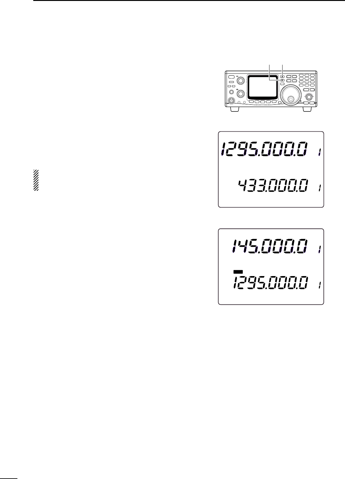
■Operating band selection (optional UX-910 is required)
The IC-910H can be used on the additional 1200 MHz
band with the optional UX-910. The operating band
can be selected by pushing [M/S•BAND] for 1 sec.
◊Selecting on the MAIN band
qPush [SUB] to cancel the SUB band access, if re-
quired.
wPush [M/S•BAND] for 1 sec. to select operating
band.
NOTE: The same operating band cannot be as-
signed on both MAIN and SUB bands, simultane-
ously.
◊Selecting on the SUB band
qPush [SUB] to enable the SUB band access.
•“SUB”indicator appears.
wPush [M/S•BAND] for 1 sec. to select operating
band.
[SUB] [M/S•BAND]
F
M
VFO A
VFVF
O
A
S 1 3 5792020 4040 60dB60dB
60dB
S13 5 7920 40
Select 1200 MHz to MAIN band.
F
M
VFO A
VFVF
O
A
F
M
S
U
B
S 1 3 5792020 4040 60dB60dB
60dB
S13 5 7920 40
Select 1200 MHz to SUB band.
21
4
BASIC OPERATION
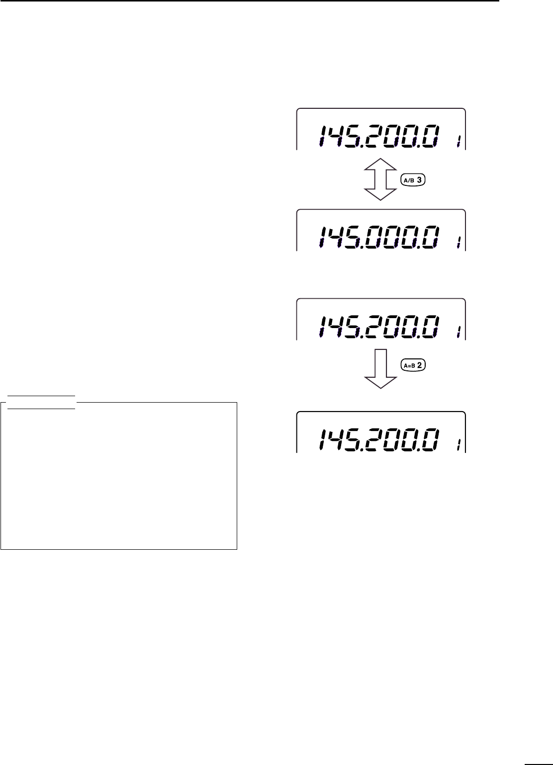
■VFO description
The IC-910H has two VFOs for both bands, specially
suited for instant selection of 2 frequencies or split fre-
quency operation. The VFOs are called VFO A and
VFO B. You can use the desired VFO to call up a fre-
quency and operating mode for your operation.
VFO is an abbreviation of Variable Frequency Oscilla-
tor, and traditionally refers to an oscillator.
◊Selecting the VFO A/B
➥Push [A/B 3] to switch between the VFO A and
VFO B.
◊VFO equalization
➥Push [A=B 2] for 1 sec. to equalize the undisplayed
VFO condition to the displayed VFO.
•3 beeps sound when the VFO equalization is completed.
Use two VFOs as a quick memory
When you find a new station, but you wish to con-
tinue searching, the two VFO system can be used
for quick memory storage.
qPush [A=B 2] for 1 sec. to store the displayed fre-
quency into the undisplayed VFO.
wContinue searching for stations.
ePush [A/B 3] to retrieve the stored frequency.
rTo continue searching for stations, push [A/B 3]
again.
CONVENIENT
F
M
VFO A
F
M
VFO B
VFO selection
F
M
VFO A
F
M
VFO B
undisplayed VFO
Equalizes the undisplayed VFO condition
to the displayed VFO.
displayed VFO
22
4BASIC OPERATION
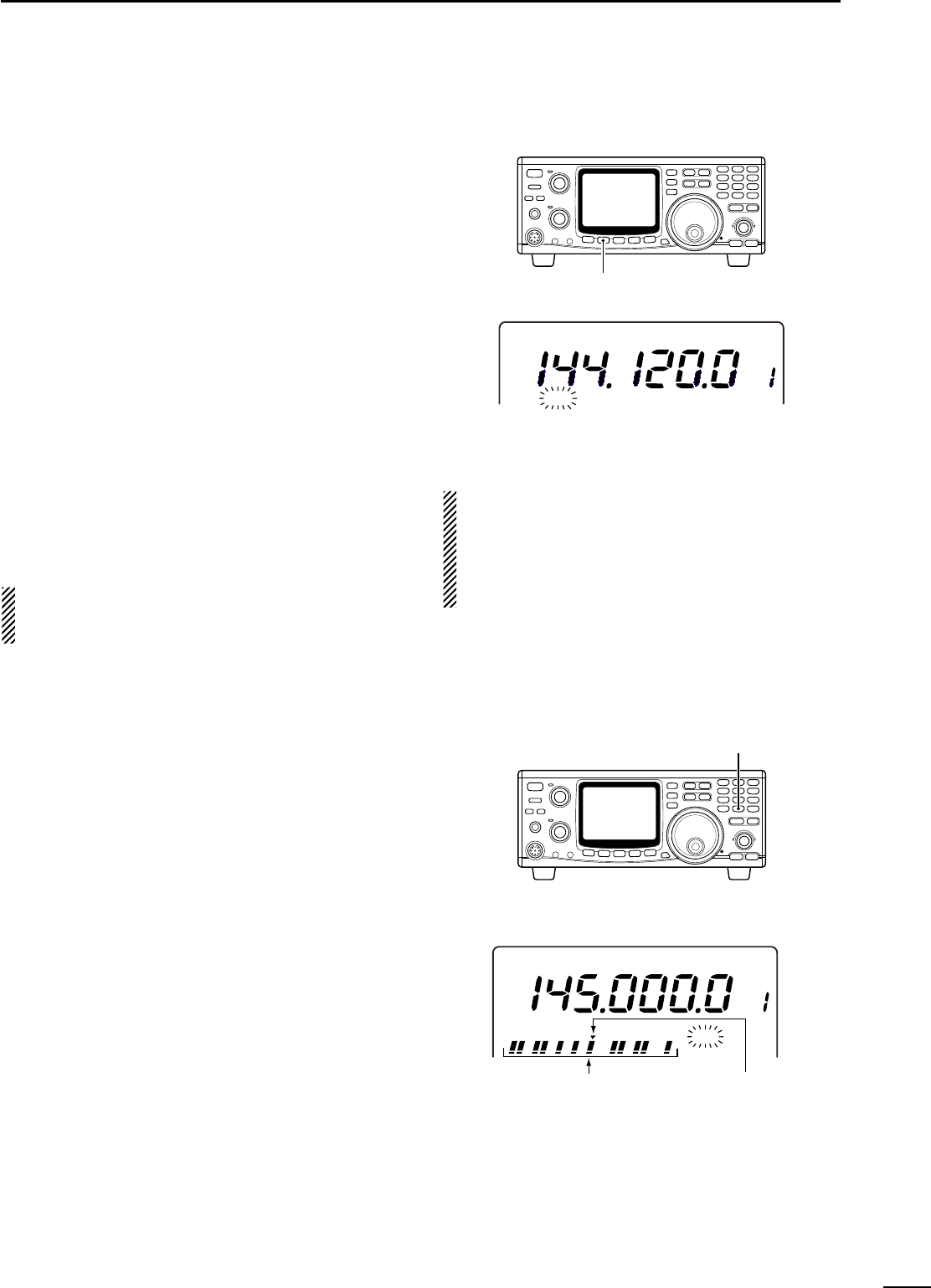
■Frequency setting
The IC-910H has several tuning steps and a
[kHz/MHz] switch for convenient frequency tuning.
qPush [M/S] to select the desired frequency band as
the MAIN band; or push [SUB] to access the SUB
band.
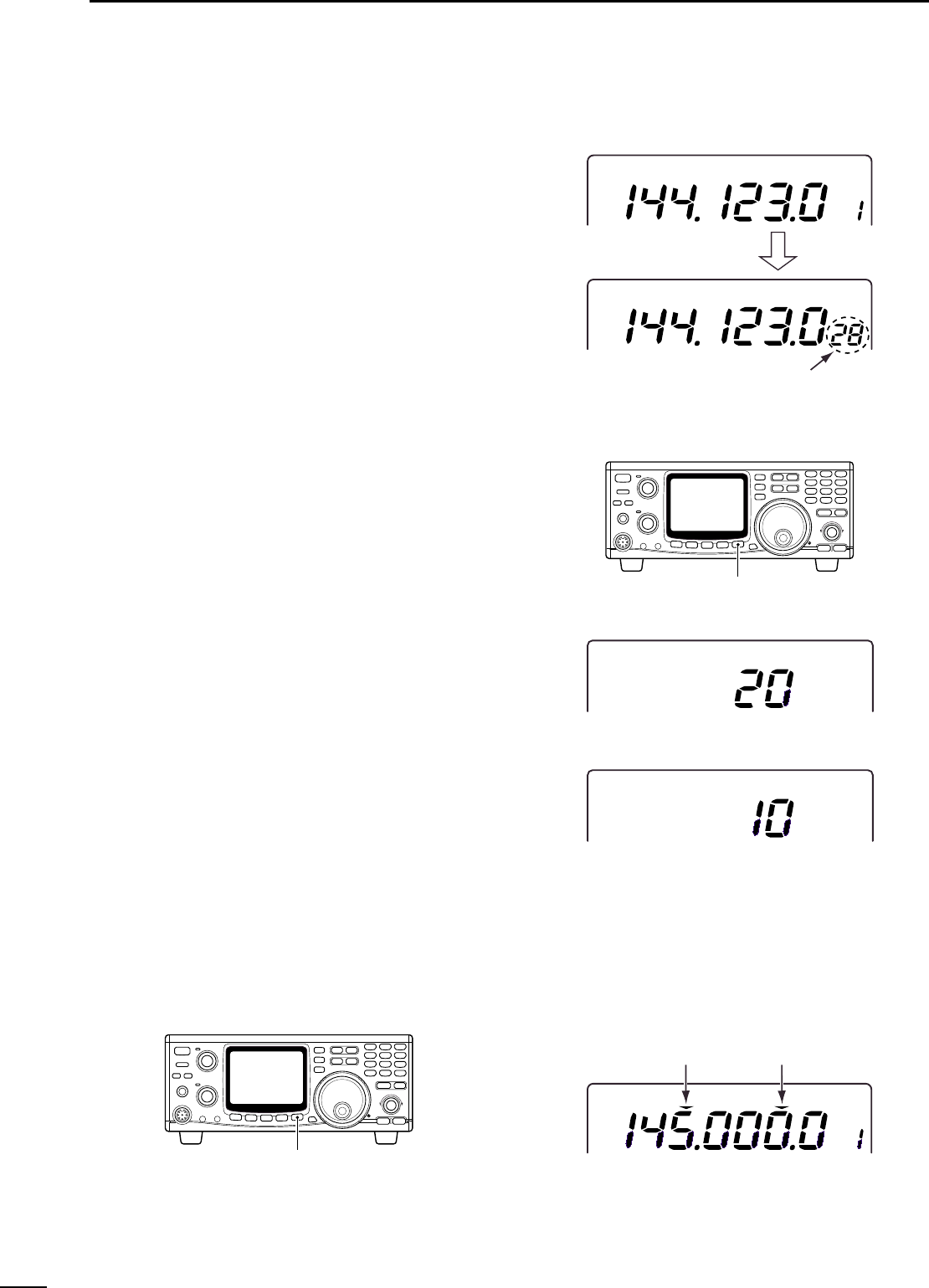
wRotate the tuning dial to select the frequency.
•The memory channel number changes to the 10 and
1 Hz digits when rotating the tuning dial with 1, 10,
100 Hz and 6.25 kHz tuning steps.
•When you want to check the 10 and 1 Hz digits during
memory channel number indication, push and hold [A/B]
(10 and 1 Hz digits are indicated while holding).
◊Tuning step selection
Tuning steps can be pre-set independently for FM and
SSB/CW. The following steps are selectable.
•FM : 0.1, 5, 6.25, 10, 12.5, 20, 25 or 100 kHz
•SSB/CW : 1, 10, 50 or 100 Hz
qPush [M/S] to select the desired frequency band as
the MAIN band; or push [SUB] to access the SUB
band.
wPush [FM] or [SSB/CW] to select the desired oper-
ation mode.
ePush [kHz/MHz•TS] for 1 sec. to enter the tuning
step set mode.
rRotate the tuning dial to select the desired tuning
step.
tPush [kHz/MHz•TS] to return to previous display.
◊Quick tuning step
The operating frequency can be changed in 1 kHz
steps or 1 MHz steps for quick tuning.
➥Push [kHz/MHz•TS] to switch the quick tuning step
in sequence 1 kHz, 1 MHz and OFF.
USBUSB
VFO A
USBUSB
10 Hz/1 Hz indication
While tuning
[kHz/MHz•TS] for 1 sec.
F
M
USBUSB
(20 kHz tuning step)
(10 Hz tuning step)
FM mode tuning step set mode
SSB/CW mode tuning step set mode
[kHz/MHz•TS]
F
M
VFO A
1 kHz tuning step1 MHz tuning step
23
4
BASIC OPERATION
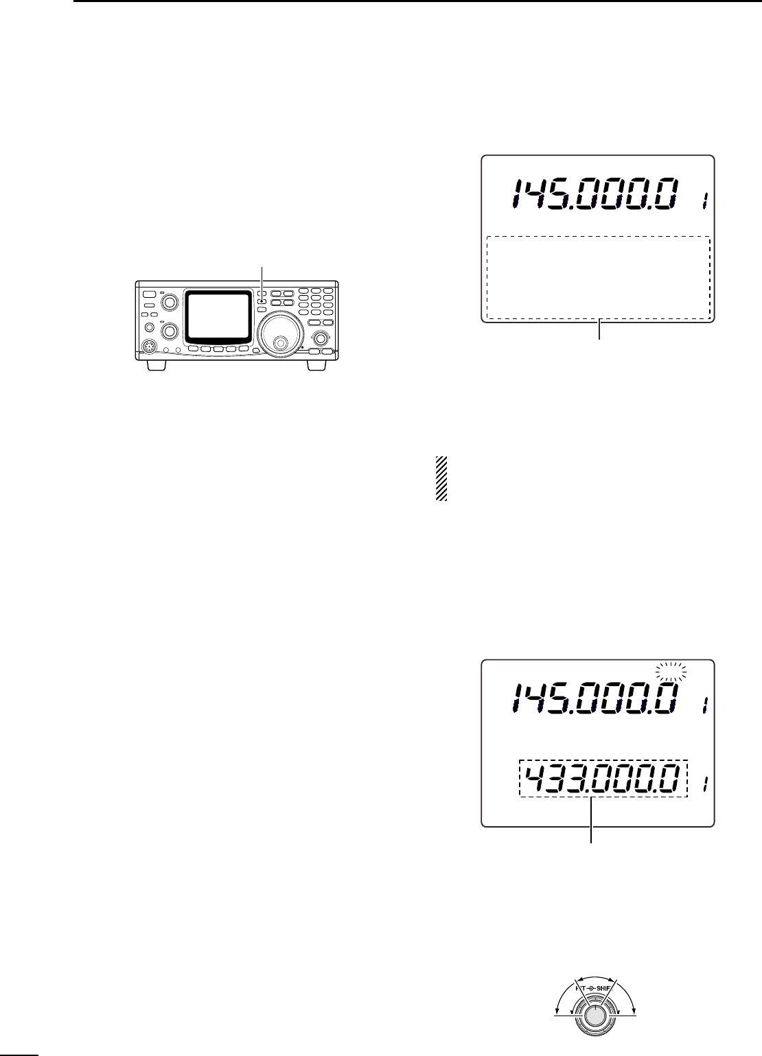
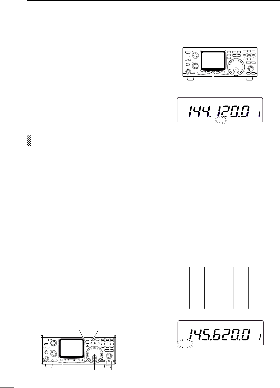
◊Frequency setting with the keypad
The operating frequency can be directly entered from
the keypad.
qPush [F-INP ENT] to access the keypad frequency
entry.
•All digits of frequency indication disappear.
wPush numeral keys to enter the desired operating
frequency.
•The entered number is indicated from the 100 Hz digit.
ePush [F-INP ENT] to set the frequency.
[EXAMPLE]
145.3400 MHz
[F-INP ENT] [1] [4] [5] [.] [3] [4] [F-INP]
435.0000 MHz
[F-INP ENT] [4] [3] [5] [.] [F-INP ENT]
439.1200 MHz
[F-INP ENT] [4] [3] [9] [.] [1] [2] [F-INP ENT]
439.1200 MHz to 439.2604 MHz
[F-INP ENT] [.] [2] [6] [0] [4] [F-INP ENT]
Pushing numeral keys to 100 Hz digit without push-
ing [.] also sets the desired operating frequency.
keypad
◊Operating mode selection
SSB (USB/LSB), CW, CW-N (CW narrow), FM and
FM-N (FM narrow) modes are available in the
IC-910H. Select the desired operation mode as follows.
•Selecting SSB mode
➥Push [SSB/CW] to select USB mode.
•USB mode is generally used for SSB phone operation
on the VHF and UHF bands.
•Push [SSB/CW] for 1 sec. after USB mode selection to
switch between USB and LSB mode.
•Selecting CW mode
➥Push [SSB/CW] to select CW mode.
•Push [SSB/CW] for 1 sec. after CW mode selection to
switch between CW and CW narrow mode.
The optional CW narrow filter, FL-132 or FL-133, is
required for the MAIN or SUB bands, respectively.
In satellite operation, the optional FL-133 is neces-
sary to operate CW narrow mode in the MAIN (re-
ceive) band. No audio is output until the optional CW
narrow filter is installed in the CW narrow mode.
•Selecting FM mode
➥Push [FM] to select FM mode.
•Push [FM] after FM mode selection to turn the repeater
mode (duplex negative with repeater tone ON) ON and
OFF.
•Push [FM] for 1 sec. after FM mode selection to switch
between FM and FM narrow mode.
[FM] [SSB/CW]
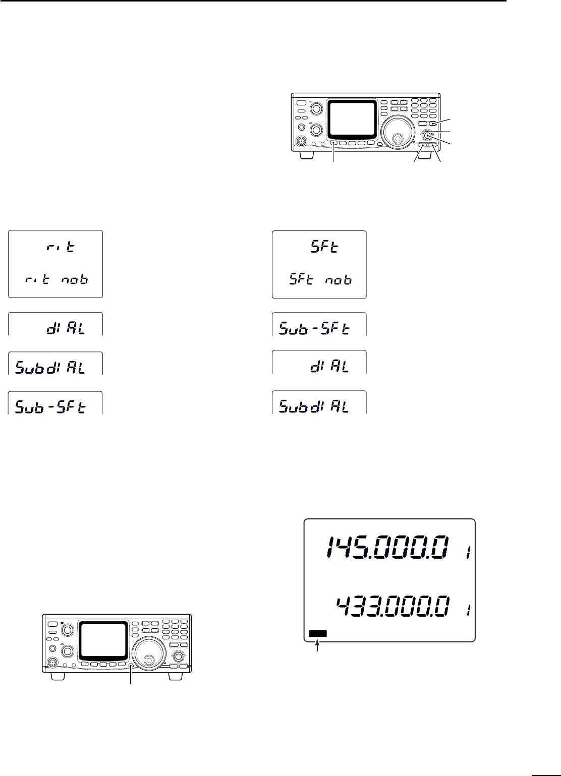
◊When the [RIT] control is assigned as
SUB tuning dial
qPush [RIT] for 1 sec.
•“RIT”indicator flashes when the SUB tuning dial func-
tion is activated.
wRotate [RIT] control for the desired tuning direction
and speed.
•Tuning speed can be adjusted in ±5 steps.
eSet [RIT] control to the center position to stops tun-
ing.
•A beep tone sounds when [RIT] control is set to the cen-
ter.
rPush [RIT] to cancel the SUB tuning dial function.
24
4BASIC OPERATION
■SUB band OFF
The SUB band indication can be deactivated to sim-
plify operation.
➥Push [SUB•SUB OFF] for 1 sec. to turn the SUB
band indication ON and OFF.
•Push [M/S•BAND] for 1 sec. to change the operating
band. (p. 20)
■SUB tuning dial
The IC-910H has a large main tuning dial for frequency
setting. In addition, the [RIT] or [SHIFT] controls can
be used as a SUB tuning dial for dual band simultane-
ous tuning, etc. The SUB tuning dial changes the op-
erating frequency continuously at a variable speed.
To use the SUB tuning dial function, assign the func-
tion to either the [RIT] or [SHIFT] control using the
RIT/SHIFT set mode.
The assigned control can be used for its original
function, however, both functions cannot be used si-
multaneously.
F
M
VFO A
60dB
S13 5 7920 40
SUB band indication OFF.
[SUB•SUB OFF] for 1 sec.
F
M
RITRIT
VFOA
VFOAVFOA
F
M
S 1 3 5792020 4040 60dB60dB
60dB
S13 5 7920 40
While [RIT] is flashing, SUB band can be
controlled with sub dial function.
Advances the
frequency and
increases the
speed.
Reverses the
frequency and
increases the
speed.
SUB dial
functions
slightly.
25
4
BASIC OPERATION
◊SUB tuning dial assignment
qPush [SET] then [RIT] to enter the RIT/SHIFT set
mode.
wPush [DN ▼] or [▲UP] to select [RIT] or [SHIFT]
control to be assigned.
•“rit nob”or “SFt nob”appears.
eRotate the tuning dial to select the condition as de-
scribed below.
•Pushing [M-CL 5] for 1 sec. selects the default setting.
rPush [SET] to exit from the RIT/SHIFT set mode.
[SET] [DN ▼][▲ UP]
[RIT]
[RIT]
[SHIFT]
The [RIT] control functions as [RIT]
even when the SUB tuning dial
function is in use. (default)
The [RIT] control can be used for
MAIN band tuning.
The [RIT] control can be used for
SUB band tuning.
The [RIT] control can be used for
SUB band IF shift control.
The [SHIFT] control functions as
[SHIFT] even when the SUB tuning
dial function is in use. (default)
The [SHIFT] control can be used for
SUB band IF shift control.
The [SHIFT] control can be used for
MAIN band tuning.
The [SHIFT] control can be used for
SUB band tuning.
■Dial lock function
The dial lock function prevents accidental changes
caused by the tuning dial (including the SUB tuning dial
function).
➥Push [SPCH•LOCK] for 1 sec. to turn the dial lock
function ON and OFF.
•“LOCK”indicator appears while the dial lock function is
activated.
F
M
VFO A
VFVF
O
A
F
M
L
OCK
S 1 3 5792020 4040 60dB60dB
60dB
S13 5 7920 40
LOCK indicatior
[SPCH•LOCK] for 1 sec.
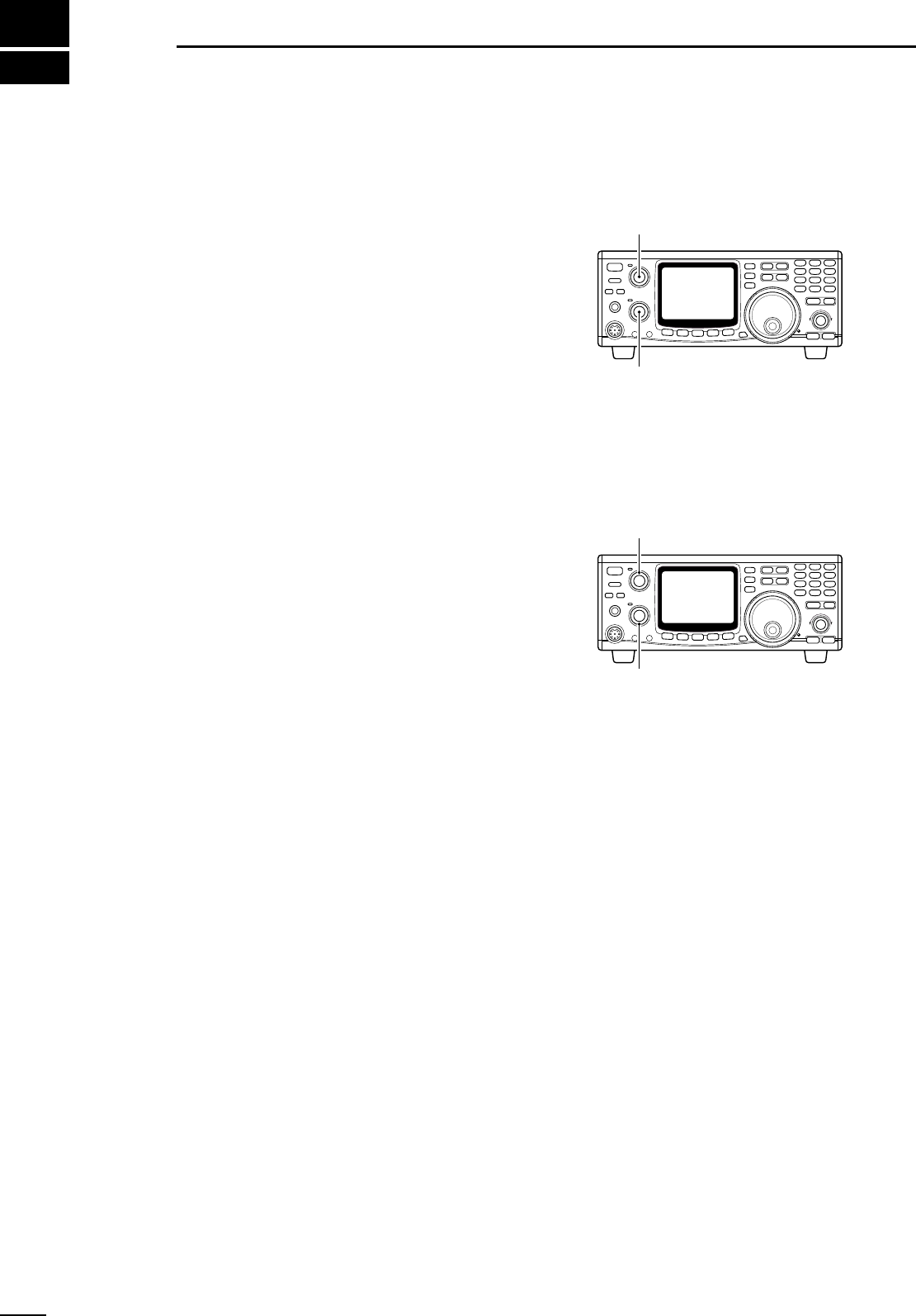
■Functions for receive
◊Volume setting
➥Rotate [AF] control for the specified operating band
(MAIN or SUB) to output a suitable audio level.
◊Squelch setting
The squelch removes noise output from the speaker
(closed position) when no signal is received. The
squelch is particularly effective for FM. It is also avail-
able for other modes.
With the default setting, noise squelch and S-meter
squelch in FM, RF gain and S-meter squelch in
SSB/CW mode operation are assigned to [RF/SQL]
control. The assignment can be changed in the gen-
eral set mode. (p. 56)
•When operating in FM
qRotate [RF/SQL] fully counterclockwise.
wRotate [RF/SQL] clockwise to the position where
the noise just disappears.
•MAIN/SUB band indicator also goes OFF.
By rotating [RF/SQL] to a deeper position (clockwise),
the S-meter will move and the S-meter squelch func-
tion will be activated. When the S-meter squelch is ac-
tivated, weak signals, weaker than the S-meter
squelch set level, are ignored.
•When operating in SSB/CW
qRotate [RF/SQL] fully counterclockwise.
wRotate [RF/SQL] clockwise to the position where
the maximum RF gain (S-meter bar disappears),
MAIN/SUB band indicator goes OFF, and floor
noise disappears.
•With the default setting, the squelch opens at 12 o’clock
position, however, the squelch threshold level can be set
to 13 o’clock (1 o’clock) position in the SSB/CW set
mode. (p. 62)
•When rotating [RF/SQL] counterclockwise, RF gain de-
creases (lower sensitivity) and the S-meter bar appears
to indicate the receivable RF signal level.
[RF/SQL] (SUB)
[RF/SQL] (MAIN)
5
26
RECEIVE AND TRANSMIT
[AF] (SUB)
[AF] (MAIN)
■RIT function
The RIT (Receive Incremental Tuning) function com-
pensates for off-frequencies of the communicating sta-
tion without moving the transmit frequency.
The RIT function can be used for the MAIN band only.
The function affects the MAIN band even when ac-
cessing the SUB band.
qPush [RIT] to turn the RIT function ON.
•“RIT”indicator appears.
wRotate [RIT] control to cancel the off-frequencies.
•Rotate [RIT] control to the center position, after commu-
nication.
ePush [RIT] to cancel the RIT function.
•“RIT”indicator disappears.
◊RIT variable range
SSB/CW mode : ±1.0 kHz in 10 Hz steps (±2.0 kHz for
optional 1200 MHz band)
FM mode : ±5.0 kHz in 50 Hz steps (±10.0 kHz
for optional 1200 MHz band)
F
M
RITRIT
FM mode
RITRIT
USBUSB
RIT variable range is displayed for 2 sec.
and then returns to frequency indication.
RIT variable range is displayed for 2 sec.
and then returns to frequency indication.
SSB mode
[RIT] control
[RIT] switch
27
5
RECEIVE AND TRANSMIT
■IF shift function
The IF shift function electronically changes the pass-
band frequency of the IF (Intermediate Frequency) and
cuts out higher or lower frequency components of the
IF to reject interference. The function shifts the IF fre-
quency up to ±1.2 kHz in 100 Hz steps in SSB/CW
mode. The IF shift is especially useful in SSB opera-
tion and not available in FM mode.
The IF shift function can be used for the SUB band
using the SUB tuning dial function (p. 24)
◊MAIN band IF shift operation
qSet the [SHIFT] control to its center position when
there is no interference.
wRotate the [SHIFT] control to adjust for minimum in-
terference signal level.
•The audio tone may change while the IF shift is in use.
◊SUB band IF shift operation
qAssign the SUB band IF shift function to either [RIT]
or [SHIFT] control using the RIT/SHIFT set mode
(p. 68).
wPush [RIT] for 1 sec. to turn the SUB tuning dial
function ON.
•“RIT”indicator flashes.
eRotate [RIT] or [SHIFT] control for a minimum inter-
ference signal level.
rPush [RIT] to cancel the SUB tuning dial function.
•“RIT”indicator disappears.
•Set [RIT] or [SHIFT] control to the center position after
the communication.
In satellite operation mode, the SUB tuning dial
function cannot be activated.Therefore, the [SHIFT]
control acts as an IF shift for the receive band (dis-
played in the upper area).
Center positionMax. counter-
clockwise position Max. clockwise
position
28
5RECEIVE AND TRANSMIT
■AGC time constant
The AGC (Automatic Gain Control) controls receiver
gain to produce a constant output level even when the
received signal strength is varied by fading, etc. Use
AGC slow for normal phone operation; AGC fast for re-
ceiving data and searching for signals.
➥Push [AGC] to switch the time constant between
fast and slow.
•“FAGC”indicator appears when AGC fast is selected.
•The AGC time constant is fixed in FM mode regardless
of the FAGC indicator.
The SUB band’s AGC is automatically selected as
slow in SSB and fast in CW. AGC time constant cannot
be changed in FM mode.
■AFC function
The AFC (Automatic Frequency Control) automatically
tunes the operating frequency when receiving an off-
frequency signal or receiving signal shifts in FM or FM
narrow mode.
➥Push [AFC/NB] to turn the AFC function ON and
OFF.
•“AFC”indicator appears when the AFC function is acti-
vated.
When strong nearby signals are available, the AFC
function may tune to those signals.
■FM center indicator
The MAIN/SUB band indicators indicate the received
signal deviation in FM mode. When an off-center sig-
nal is received, the indicator flashes.
When an off-center signal is received, rotate the tun-
ing dial or use the RIT function to illuminate the indica-
tor continuously.
The FM center indicator can be turned OFF using the
FM set mode. (p. 61)
[AGC]
C
W
VFO A
F
AGCAGC
[AFC/NB]
F
M
VFO A
AFCAFC
Flashes in 300 msec. intervals.
■Attenuator
The attenuator prevents desired signals from distorting
when very strong signals are near the desired fre-
quency, or when very strong electric fields, such as
from broadcasting stations are near from your location.
The attenuator can be set to both or either band sepa-
rately, and the attenuation level can be set for each
band independently.
➥Push [ATT] to turn the attenuator ON and OFF.
•“ATT”indicator appears when the attenuator is activated.
◊Setting the attenuation level
qPush [M/S•BAND] or [SUB] to select the desired
band of the attenuation level to be set.
wPush [SET] then [ATT] to enter the attenuator set
mode.
eRotate the tuning dial to select attenuation level.
•Push [M-CL 5] to return to the default value.
rPush [SET] to exit the attenuator set mode.
NOTE: When using the noise blanker, received
audio may be distorted if they are excessively
strong.
■Simple band scope
This function allows you to visually “sweep”an area
surrounding the set frequency for other signals. De-
tected signals are indicated graphically on the S-meter.
qSet the operating frequency and mode.
wPush [SWP 0] to turn the simple band scope func-
tion ON and OFF.
•“SWP”indicator flashes when the simple band scope
function is activated.
•Detected signals are indicated using the S-meter and
“▼”indicator, displayed above the S-meter, shows the
center frequency (displayed frequency).
•The signal availability is detected by the noise squelch
condition (open or close).
eTo monitor the detected signal, rotate the tuning dial
to set the appearing “dot”of the S-meter to below
the “▼”indicator.
•The frequency readout shows the detected signal fre-
quency.
◊Setting sweeping time interval
qPush [SET] then [SWP 0] to enter the sweep set
mode.
wRotate the tuning dial to select sweeping time inter-
val.
•Push [M-CL 5] to return to the default value.
ePush [SWP 0] to exit the sweep set mode.
29
5
RECEIVE AND TRANSMIT
[ATT]
C
W
VFO A
A
TT
[SWP 0]
F
M
VFOA
S
W
P
Indicates detected signals Sweep center
Shows ±10 channels around the displayed
frequency.
Attenuation levels
144 MHz/ 0–100% variable
430(440) MHz bands Approx. 15 dB attenuation
at 100% setting
1200 MHz band Approx. 20 dB fixed
(optional)
30
5RECEIVE AND TRANSMIT
■Noise blanker
When operating in SSB or CW mode, pulse-type noise
may be received such as from car ignitions. In this
case, the noise blanker eliminates such noise.
The noise blanker is effective on both the MAIN and
SUB bands but cannot be used for FM, or non-pulse-
type noise.
➥Push [AFC/NB] to turn the noise blanker function
ON and OFF.
•“NB”indicator appears when the noise blanker is acti-
vated.
•The noise blanker turns ON or OFF for both bands si-
multaneously.
When using the noise blanker, received audio may
be distorted if the signals are excessively strong.
■Tone squelch operation
The tone squelch opens only when receiving a signal
with the same pre-programmed subaudible tone. You
can silently wait for a call from group members using
the same tone.You can check the tone frequency using
the tone scan function if desired. (p. 47)
qSelect the desired band by pushing [M/S•BAND].
wPush [FM] to select FM mode, then set the desired
frequency.
ePush [CALL•T-SQL] for 1 sec. to activate the tone
squelch.
•“T-SQL”indicator appears.
rWhen the signal with correct tone is received, the
squelch opens and audio can be heard.
•When a signal with incorrect tone or no tone is received,
the squelch does not open, however, the S-meter indi-
cates the signal strength.
•Push and hold [CHECK 7] to open the squelch manually
and keep pushing to monitor.
tOperate the transceiver in a normal way (push
[PTT] to transmit; release [PTT] to receive).
yPush [CALL•T-SQL] for 1 sec. to cancel the tone
squelch.
•“T-SQL”indicator disappears.
◊Setting the tone squelch frequency
The tone squelch frequencies can be independently
set for each band.
qPush [M/S•BAND] to select the band for the tone
squelch frequency to be set.
wPush [SET] then [FM] to enter the FM set mode.
ePush [DN ▼] or [▲UP] to select tone squelch fre-
quency item.
rRotate the tuning dial to select the desired tone
squelch frequency.
tPush [FM] to exit from the FM set mode.
Tone frequency list unit: Hz
F
M
VFO A
T-SQ
L
[SET] Tuning dial
[FM][CALL•T-SQL]
[DN √]/[∫ UP]
67.0
69.3
71.9
74.4
77.0
79.7
82.5
085.4
088.5
091.5
094.8
097.4
100.0
103.5
107.2
110.9
114.8
118.8
123.0
127.3
131.8
136.5
141.3
146.2
151.4
156.7
159.8
162.2
165.5
167.9
171.3
173.8
177.3
179.9
183.5
186.2
189.9
192.8
196.6
199.5
203.5
206.5
210.7
218.1
225.7
229.1
233.6
241.8
250.3
254.1
[AFC/NB]
C
W
VFO A
N
B
31
5
RECEIVE AND TRANSMIT
■Optional DSP functions
To activate the following functions, the optional DSP
unit, UT-106, must be installed for both or either the
MAIN and/or SUB bands.
◊NR (Noise Reduction) function
This function reduces noise components and picks out
desired signals which are buried in noise.The received
audio signals are converted to digital signals and then
the desired signals are separated from the noise. The
noise reduction function is available for all operating
modes.
qPush [M/S•BAND] or [SUB] to select the band you
wish to activate, if required.
wPush [AFC/NB•NR] for 1 sec. to turn the noise re-
duction function ON and OFF.
•“NR”indicator appears while the automatic notch filter is
activated.
◊Setting the noise reduction level
qPush [SET] then [AFC/NB•NR] to enter the noise
reduction set mode.
wRotate the tuning dial to select the desired noise re-
duction level.
•Push [M-CL 5] for 1 sec. to return to the default value.
ePush [AFC/NB•NR] to exit from the noise reduction
set mode.
USBUSB
VFO A
N
R
[AFC/NB•NR] for 1 sec.
◊ANF (Automatic Notch Filter) function
This function automatically attenuates beat tones, tun-
ing signals, etc., even if they are moving. The auto-
matic notch filter functions in SSB/FM modes.
qPush [M/S•BAND] or [SUB] to select the band you
wish to activate, if required.
wPush [AGC•ANF] for 1 sec. to turn the automatic
notch filter function ON and OFF.
•“ANF”indicator appears while the automatic notch filter
is activated.
USBUSB
VFO A
ANFANF
[AGC•ANF] for 1 sec.
Unwanted tone
frequency
Desired
signal (AF) Desired
signal (AF)
Particular frequency
is attenuated
Auto notch OFF Auto notch ON
optional UT-106
32
5RECEIVE AND TRANSMIT
■Functions for transmit
◊Output power
The transmit output power can be continuously ad-
justed with [RF PWR].
Available power
144 MHz band : 5–100 W
430(440) MHz band : 5–75 W
1200 MHz band : 1–10 W (optional)
NOTE: To prevent interference, listen on the fre-
quency to make sure the frequency is clear before
transmitting by pushing [CHECK 7].
[RF PWR]
■Transmission via
microphone
When transmitting with a microphone, push [PTT] and
speak into the microphone at a normal voice level.
To maximize the readability of your transmitted sig-
nal (voice), pause a few sec. after pushing [PTT]. Do
not hold the microphone too close to your mouth.
◊Microphone gain
Rotate [MIC GAIN] clockwise to increase, counter-
clockwise to decrease the microphone gain.
9–12 o’clock position is recommended for [MIC GAIN].
[PTT] switch
HM-12
■Indications during transmit
◊Transmit indicator
The MAIN band indicator lights red while transmitting.
However, the SUB band indicator lights red during
satellite operation.
◊RF power indicator
The S-meter for the MAIN band is used as the RF
power indicator to indicate the relative output power
level. However, the S-meter for the SUB band is used
as the RF power indicator during satellite operation.
◊Time-out timer
The time-out timer limits the continuously transmittable
time period, and is selectable from 3, 5, 10, 20, 30 min.
and OFF in TRANSMIT set mode. (p. 66)
◊PTT lock function
Deactivate [PTT] and [TRANSMIT] switches. The func-
tion can be switched ON and OFF in TRANSMIT set
mode. (p. 66)
S-meter while receiving
RF power indicator while transmitting
F
M
VFO A
VFVF
O
A
F
M
S 1 3 5792020 4040 60dB60dB
60dB
OVER
S13 5 7920 40
OVEROVER
33
5
RECEIVE AND TRANSMIT
■FM mode operation
qPush [M/S•BAND] to select the desired band.
wPush [FM] to select FM mode.
•“FM”indicator appears.
•Push [FM] again to select repeater operation after FM
mode selection. “DUP–” and “T”indicators appear.
•Push [FM] for 1 sec. to select FM narrow mode after FM
mode selection. “FMN”indicator appears.
eRotate the tuning dial to set the desired frequency.
rPush [PTT] to transmit.
•The MAIN band indicator lights red.
tSpeak into the microphone at a normal voice level.
•Setting the [MIC GAIN] control to 10–12 o’clock is rec-
ommended.
yRelease [PTT] to receive.
Tuning dial
[FM][M/S•BAND][TRANSMIT]
[MIC GAIN]
■VOX operation (for SSB and FM)
The VOX (Voice-operated Transmission) function
switches between transmit and receive with your voice.
This function provides an opportunity to input log en-
tries into your computer, etc., while operating.
qPush [M/S•BAND] to select the desired band.
wPush either [SSB/CW] or [FM] to select phone
mode (USB, LSB or FM).
ePush [VOX] to switch the VOX function ON and
OFF.
•“VOX”indicator appears while the VOX function is acti-
vated.
◊Adjusting the VOX gain
qPush [SET] then [VOX] to enter the VOX set mode.
wPush [DN ▼] or [▼UP] to select the VOX gain item.
•“GAIn”is displayed.
eRotate the tuning dial to adjust the VOX gain while
speaking into the microphone at a normal voice
level, until the transceiver begins transmitting.
•With too sensitive a setting, the transceiver may trans-
mit with other than your voice, such as noise, receiving
signal, etc.
•Push [M-CL 5] for 1 sec. to return to the default value.
rPush [VOX] to exit VOX set mode.
◊Adjusting the anti-VOX gain
qPush [SET] then [VOX] to enter the VOX set mode.
wPush [DN ▼] or [▲UP] to select anti-VOX gain
item.
•“Anti”is displayed.
eRotate the tuning dial to adjust the anti-VOX gain
while receiving a signal with a suitable audio output
level, to the point where the transceiver does not
transmit with the audio output from the speaker.
•Push [M-CL 5] for 1 sec. to return to the default value.
rPush [VOX] to exit VOX set mode.
◊Adjusting the VOX delay
qPush [SET] then [VOX] to enter the VOX set mode.
wPush [DN ▼] or [▲UP] to select the VOX delay
item.
•“dELAy”is displayed.
eRotate the tuning dial to adjust the VOX delay time
while speaking into the microphone at a normal
speed, to a convenient interval before returning to
receive.
•Push [M-CL 5] for 1 sec. to return to the default value.
rPush [VOX] to exit VOX set mode.
34
5RECEIVE AND TRANSMIT
■Repeater operation
A repeater amplifies received signals and re-transmits
them at a different frequency. When using a repeater,
the transmit frequency is shifted from the receive fre-
quency by an offset frequency.
◊Setting the auto repeater range
The auto repeater function automatically turns ON the
duplex operation with specified shift direction and tone
encoder when the operating frequency is set in the de-
sired frequency range. To activate the auto repeater
function, the following operations are necessary.
qSet one edge frequency of the desired frequency
range.
•Push [M/S•BAND] to select the desired band if required.
•Push [FM] to select FM mode if required.
wSet the desired repeater conditions.
•Both one-touch repeater and manual repeater setting
are acceptable.
ePush [DN▼] or [▲UP] to select the memory chan-
nel 1.
•The memory channel 3 or 5 is also acceptable.
rPush [MW 4] for 1 sec. to program the contents into
the memory.
•3 beep tones may sound.
tSet the other side edge frequency of the desired
frequency range.
yPush [▲UP] to select the memory channel 2.
•Select memory channel 4 or 6, respectively if the mem-
ory channel 3 or 5 is selected in step e.
uPush [MW 4] for 1 sec. to program the contents into
the memory.
iRepeat steps qto uto program other ranges.
oPush [POWER] for 1 sec. to turn the power OFF
once, then push [POWER] to turn the power ON
while pushing and holding [FM] and [TONE].
•The memory channels can be used for normal operation
after programming.
!0 Push [SET] then [FM] to enter the FM set mode.
!1 Push [DN▼] or [▲UP] to select auto repeater item.
•“AutorPt”is displayed.
!2 Rotate the tuning dial to turn the auto repeater func-
tion ON.
U.S.A. version:
•“on1”Activates duplex only.
•“on2”Activates duplex and tone.
•“oFF”Auto repeater function is turned OFF.
Korea version:
•“ON”Activates duplex and tone.
•“OFF”Auto repeater function is turned OFF.
!3 Push [FM] to exit from the FM set mode.
NOTE: All repeater ranges for available bands must
be programmed at the same time. Otherwise, the
previously programmed ranges will be lost.
◊Frequency range and shift direction
•U.S.A. version
•Korea version
FREQUENCY RANGE SHIFT DIRECTION
1439.0000–1440.0000 MHz “DUP–” appears
1290.0000–1293.0000 MHz “DUP–” appears
FREQUENCY RANGE SHIFT DIRECTION
1145.2000–1145.4999 MHz
1146.6100–1146.9999 MHz “DUP–” appears
1147.0000–1147.3999 MHz “DUP+” appears
1442.0000–1444.9999 MHz “DUP+” appears
1447.0000–1449.9999 MHz “DUP–” appears
1282.0000–1295.9999 MHz “DUP–” appears
◊Setting the shift direction for the one-
touch repeater function
qPush [M/S•BAND] or [SUB] to select the desired
frequency band.
wPush [SET] then [FM] to enter the FM set mode.
ePush [DN▼] or [▲UP] to select shift direction item.
•“o_touch”and “rPt”are displayed.
rRotate the tuning dial to select the desired direction.
•“DUP–” or “DUP+”is selectable.
tPush [FM] to exit from the FM set mode.
◊Manual repeater setting
(non-European versions)
qSet the desired frequency.
•Push [M/S•BAND] to select the desired band if required.
•Push [FM] to select FM mode if required.
wPush [SPLIT•DUP] for 1 sec. to select the duplex
operation and the shift direction.
•“DUP–” or “DUP+”indicator appears, depending on the
selection.
•Set the offset frequency in the FM set mode, if required.
ePush [TONE] to activate the tone encoder.
•“T”indicator appears.
•Set the tone frequency in the FM set mode, if required.
rPush [SPLIT•DUP] for 1 sec. and [TONE] to cancel
the duplex operation and deactivate the tone en-
coder.
•“DUP–” or “DUP+”and “T”indicators disappear.
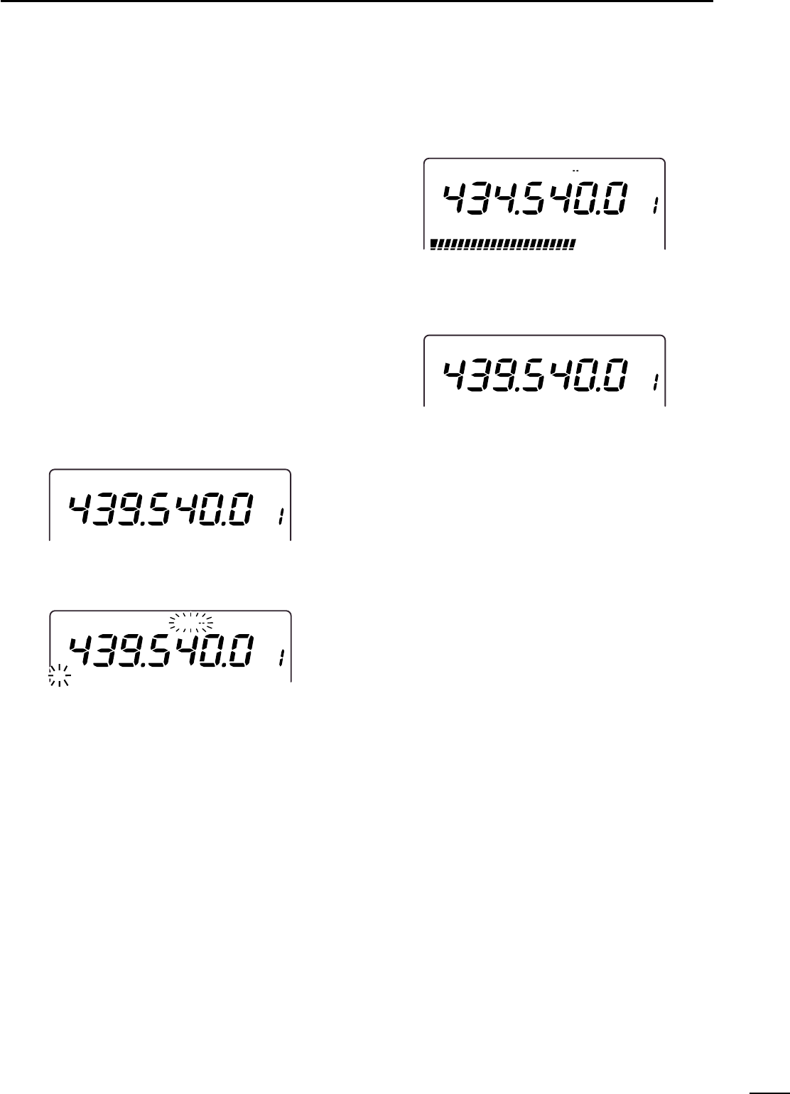
35
5
RECEIVE AND TRANSMIT
◊Using the one-touch repeater function
By using the pre-programmed offset frequency, shift di-
rection and tone frequency, quick and simple repeater
operation can be made.
The default values for offset frequency and direction
are as follows:
144 MHz band : –0.600 MHz
430(440) MHz band : –5.000 MHz (other than below)
–7.200 MHz (
European version
)
–1.600 MHz (Swedish version)
1200 MHz band : –20.000 MHz (optional)
Tone frequency : 88.5 Hz
qPush [M/S•BAND] to select the desired frequency
band.
wPush [FM] to select FM mode.
eRotate the tuning dial to input the desired repeater
frequency.
•Direct frequency input using the keypad can be used for
frequency setting.
rPush [FM] to select the repeater operation mode.
•“DUP–” and “T”indicators appear.
tPush [PTT] to access the repeater.
yRelease [PTT] to receive a signal from the repeater.
uPush [FM] to cancel the duplex operation mode.
•“DUP–” and “T”indicators disappear.
F
M
VFO A
F
M
DUP
VFO A
T
60dB
S13 5 7920 40
Shifts 5 MHz when transmitted.
F
M
DUP
VFO A
T
F
M
VFO A
◊Setting tone frequency
(non-European versions)
qPush [M/S•BAND] to select the desired frequency
band.
wPush [SET] then [FM] to enter the FM set mode.
ePush [DN▼] or [▲UP] to select the tone frequency
item.
•“ton,”selected band (144/430(440)/1200) and “T”indica-
tor appear.
rRotate the tuning dial to set the desired tone fre-
quency.
tPush [FM] to exit from the FM set mode.
◊Setting offset frequency
qPush [M/S•BAND] or [SUB] to select the desired
frequency band.
wPush [SET] then [FM] to enter the FM set mode.
ePush [DN▼] or [▲UP] to select the offset frequency
item.
•“duP”and selected band (144/430(440)/1200) appear.
rRotate the tuning dial to set the desired tone fre-
quency.
tPush [FM] to exit from the FM set mode.
36
5RECEIVE AND TRANSMIT
■SSB mode operation
qPush [M/S•BAND] to select the desired frequency
band.
wPush [SSB/CW] to select USB or LSB mode.
•Push [SSB/CW] for 1 sec. to switch between USB and
LSB when either the USB or LSB has been selected.
eRotate the tuning dial to set the desired frequency.
rPush [PTT] to transmit and speak into the micro-
phone at a normal voice level.
tRotate [MIC GAIN] so that the MAIN band indicator
periodically lights red brightly.
•The brightness increases when the ALC is activated.
yRelease [PTT] to receive.
Tuning dial
[SSB/CW][M/S•BAND][TRANSMIT]
[MIC GAIN]
■Speech compressor
The speech compressor increases average RF output
power, improving signal strength and readability in
SSB.The IC-910H has a built-in, low-distortion speech
compressor circuit.
➥Push [COMP] to turn the speech compressor ON
and OFF.
•Either USB or LSB should be selected.
•“COMP”indicator appears when the speech compressor
is activated.
◊Compression level setting
qSelect USB or LSB mode.
wPreset the transceiver as follows:
[COMP] function : OFF
[RF POWER] control : Max. counterclockwise
eTransmit at your normal voice level.
rAdjust the [MIC GAIN] control so that the MAIN
band indicator periodically lights red brightly
whether or not you speak softly or loudly.
tPush [COMP] to turn the speech compressor ON.
yPush [SET] then [COMP] to enter the COMP set
mode.
uRotate the tuning dial to adjust the compression
level to the point where the maximum value and the
MAIN band indicator brightness does not increase,
whether or not you speak softly or loudly.
•When the MAIN band indicator continuously lights red
with increased brightness, your transmitted voice may be
distorted.
•It’s a good idea to adjust the compressor level by moni-
toring with an other transceiver or receiver, if you have
one, or with an other station.
iPush [COMP] to exit the COMP set mode.
[MIC GAIN]
[COMP] MAIN band LED
lights in red while transmitting.
ALC indicator
While transmitting, the MAIN/SUB band indicator
shows the ALC condition. Brightness increases
more than usual when the ALC function is activated.
VOX function
The VOX (Voice-operated Transmission) function is
available for switching between transmit and receive
with your voice. See p. 33 for details.
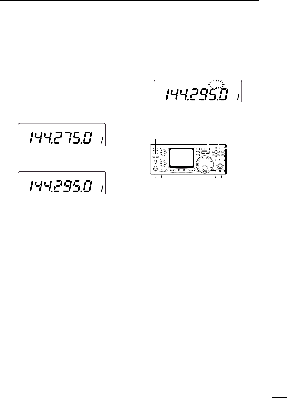
37
5
RECEIVE AND TRANSMIT
■Split frequency operation
Split frequency operation allows you to transmit and re-
ceive on two different frequencies in the same fre-
quency band. Split frequency operation uses 2 fre-
quencies, one in VFO A and the other in VFO B.
qSet a receive frequency in VFO mode.
•Either VFO A or VFO B can be used.
wPush [A=B 2] for 1 sec.
•The undisplayed VFO contents are cleared and equal-
ized to the displayed frequency.
eTo change the receive frequency, rotate the tuning
dial.
rTo replace the transmit and receive frequencies,
push [A/B 3].
tTo change the transmit frequency, rotate the tuning
dial while pushing [CHECK 7].
yPush [SPLIT].
•“SPLIT”indicator appears.
•Now you can receive on the displayed VFO and transmit
on the undisplayed VFO.
•To monitor the transmit frequency, push [CHECK 7].
uPush [SPLIT] to cancel the split frequency opera-
tion.
•“SPLIT”indicator disappears.
Cross mode communication can be performed using
the split function. (e.g. USB and CW)
[A=B 2]
[A/B 3]
[SPLIT]
[TRANSMIT]
USBUSB SPLITSPLIT
VFO B
USBUSB
VFO B
USBUSB
VFO A
■Full duplex operation
The MAIN and SUB bands are activated indepen-
dently, therefore, simultaneous transmission and re-
ception in different frequency bands are possible.
qPush [M/S•BAND] to select the desired frequency
band for transmission.
•Push [V/M 1] to select VFO or memory mode, if desired.
•Push [SSB/CW] or [FM] to select the desired operating
mode.
wRotate the tuning dial to set the desired frequency.
•Direct frequency input from the keypad is also available.
ePush [SUB] to enable the SUB band access.
•Push [M/S•BAND] for 1 sec. to select the desired fre-
quency band, if desired. (when the optional UX-910 is in-
stalled.)
•Push [V/M 1] to select VFO or memory mode, if desired.
•Push [SSB/CW] or [FM] to select the desired operating
mode.
rPush [PTT] to transmit.
•SUB band mute function
The SUB band mute function mutes receiving audio
from the SUB band while transmitting.
qPush [SET] then [TRANSMIT] to enter the TRANS-
MIT set mode.
wPush [DN ▼] or [▲UP] to select the SUB band
mute item.
•“Audio”is displayed.
eRotate the tuning dial to turn the SUB band mute
function ON and OFF.
•Push [M-CL 5] for 1 sec. to return to the default setting.
rPush [TRANSMIT] to exit from the TRANSMIT set
mode.
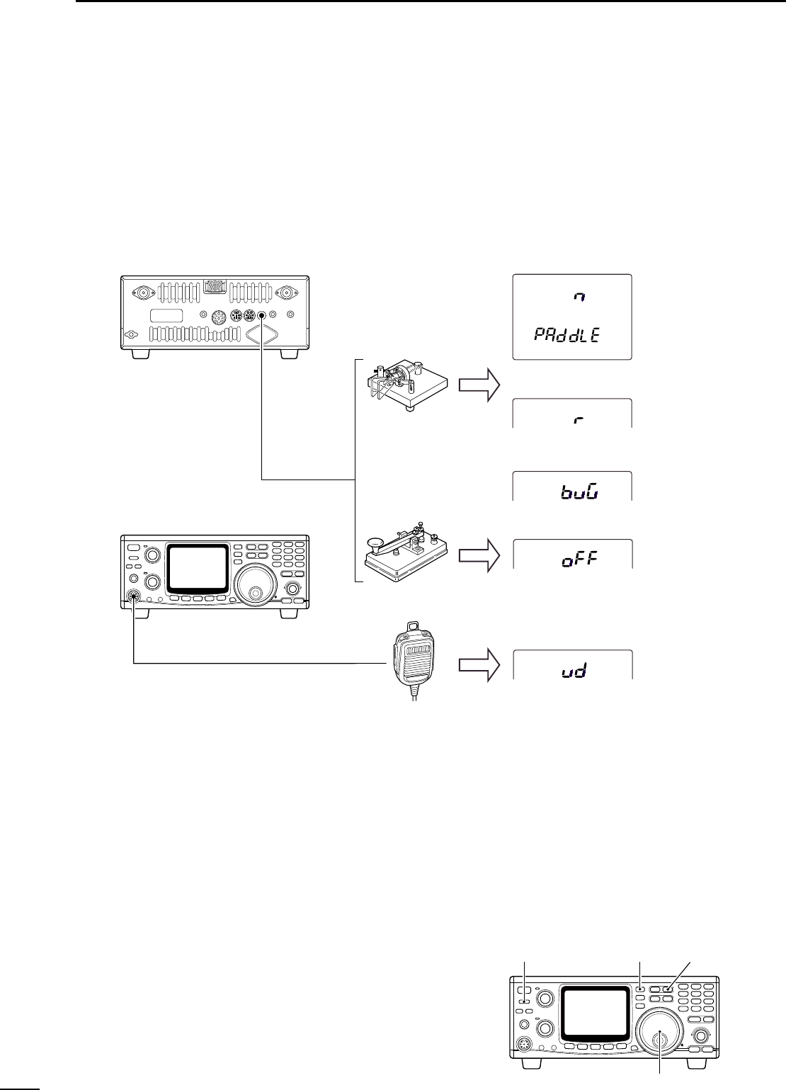
38
5RECEIVE AND TRANSMIT
■Connections for CW
Before operating in CW, select the paddle type using
the SSB/CW set mode.
qPush [SSB/CW] to select CW mode.
•“CW”indicator appears.
wPush [SET] then [SSB/CW] to enter the SSB/CW
set mode.
ePush [DN▼] or [▲UP] to select the paddle type
item.
•“PAddLE”is displayed.
rRotate the tuning dial to select the paddle type.
•Push [M-CL 5] for 1 sec. to return to the default setting.
tPush [SSB/CW] to exit the SSB/CW set mode.
■CW mode operation
qConnect a paddle or straight key as above.
wPush [M/S•BAND] to select the desired frequency
band.
ePush [SSB/CW] to select CW mode.
•Push [SSB/CW] for 1 sec. to select CW narrow mode
after the CW mode selection when the optional CW nar-
row filter, FL-132 (for MAIN band) or FL-133 (for SUB
band), is installed.
rRotate the tuning dial to set the operating fre-
quency.
tPush [TRANSMIT] to set the transceiver to transmit
mode.
•The MAIN band indicator lights red.
yOperate the paddle or key to transmit the CW sig-
nal.
uPush [TRANSMIT] to return to receive mode.
Tuning dial
[SSB/CW][M/S•BAND][TRANSMIT]
CW
Paddle
Straight key
Microphone
[KEY] jack
[MIC] connector
CW paddle with normal polarity (default)
CW paddle with reverse polarity
CW paddle use as bug-key
Electronic keyer OFF (straight key)
Substitute paddle function
(microphone [UP]/[DN])
NOTE: A stereo plug must be used even when a
straight key is used. See page 12 or 15.
NOTE: [UP]/[DN] keying does not function while
pushing [PTT] on the microphone. Push [TRANS-
MIT] on the front panel or use the semi break-in
function in this case.

39
5
RECEIVE AND TRANSMIT
◊Setting keying speed
qPush [SET] then [SSB/CW] to enter the SSB/CW
set mode.
wPush [DN▼] or [▲UP] to select the keying speed
item.
•“SPEEd”is displayed.
eRotate the tuning dial to adjust the keying speed to
the desired speed.
•Keying speed can be selected from 6–60 wpm.
•Push [M-CL 5] for 1 sec. to return to the default value.
rPush [SSB/CW] to exit the SSB/CW set mode.
◊Setting semi break-in function
qPush [SET] then [SSB/CW] to enter the SSB/CW
set mode.
wPush [DN▼] or [▲UP] to select the semi break-in
item.
•“br-In”is displayed.
eRotate the tuning dial to turn the semi break-in func-
tion ON and OFF.
•Push [M-CL 5] for 1 sec. to return to the default setting.
rPush [DN▼] or [▲UP] to select the delay time item.
•“dELAy”is displayed.
tRotate the tuning dial to set the delay time to the
desired time period.
•Delay time can be selected from 2.0–13.0 sec. in
0.1 sec. steps.
•Push [M-CL 5] for 1 sec. to return to the default value.
yPush [SSB/CW] to exit the SSB/CW set mode.
◊Setting keying weight
qPush [SET] then [SSB/CW] to enter the SSB/CW
set mode.
wPush [DN▼] or [▲UP] to select the keying weight
item.
•“rAtio”is displayed.
eRotate the tuning dial to adjust the keying weight
ratio to the desired level.
•Keying weight ratio can be selected from 1:1:2.8 to
1:1:4.5.
•Push [M-CL 5] for 1 sec. to return to the default value.
rPush [SSB/CW] to exit the SSB/CW set mode.
◊Setting CW pitch
qPush [SET] then [SSB/CW] to enter the SSB/CW
set mode.
wPush [DN▼] or [▲UP] to select the CW pitch item.
•“Pitch”is displayed.
eRotate the tuning dial to adjust the CW pitch to the
desired pitch.
•CW pitch can be adjusted within 300–900 Hz range.
•Push [M-CL 5] for 1 sec. to return to the default value.
rPush [SSB/CW] to exit the SSB/CW set mode.
◊Setting side tone
qPush [SET] then [SSB/CW] to enter the SSB/CW
set mode.
wPush [DN▼] or [▲UP] to select the side tone item.
•“SidE-t”is displayed.
eRotate the tuning dial to adjust the side tone level
to the desired level.
•Push [M-CL 5] for 1 sec. to return to the default value.
rPush [SSB/CW] to exit the SSB/CW set mode.
KEYING WEIGHT EXAMPLE: Morse code “K”
DASH
Weight setting:
1:1:3 (default)
Weight setting:
Adjusted
DASH
DOT
(Fixed*)
Adjustable range SPACE (Fixed*)
*SPACE and DOT length can be adjusted with the
keying speed only.
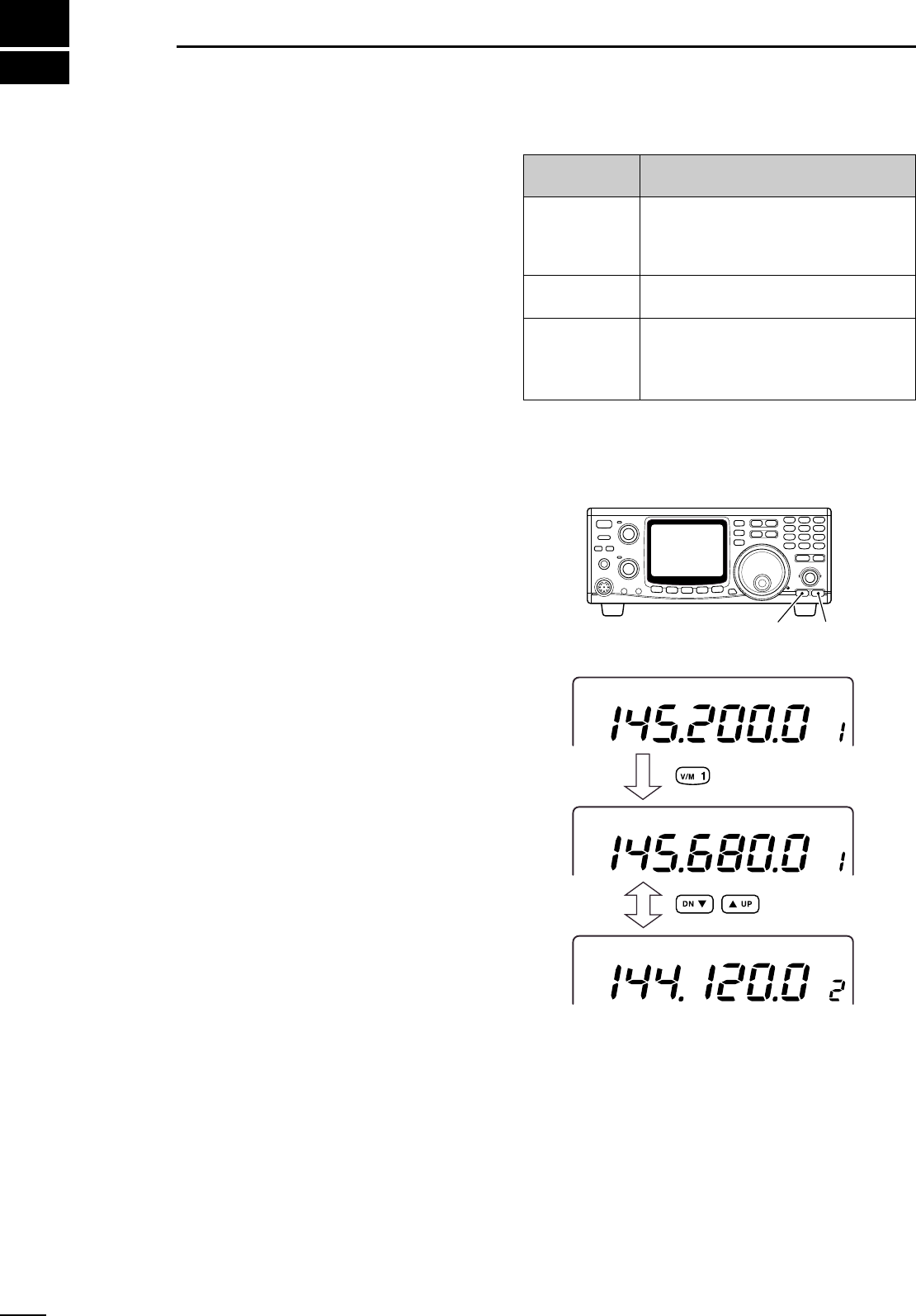
6
40
MEMORY OPERATION
■Memory channels
The IC-910H has 106 memory channels (99 for regu-
lar, 6 scan edges and 1 call) and they are equipped for
each frequency band for storing the most often used
frequencies and operating mode, as well as tone fre-
quency, offset frequency, etc.
■Operation on a memory
channel
Frequency and mode, etc., can be changed in a mem-
ory channel. However, they will be cleared if [MW 4] is
not pushed.
◊Memory channel selection
qPush [V/M 1] to select memory channel mode.
•“MEMO”indicator appears.
wPush [DN▼] or [▲UP] to select the desired mem-
ory channel.
•Memory channel changes continuously while holding
[DN▼] or [▲UP].
•The tuning dial rotation while pushing [F-INP ENT] also
selects memory channel.
ePush [V/M 1] to return to VFO mode.
◊During VFO mode operation
By pushing [DN▼] or [▲UP] during VFO mode opera-
tion, memory channel is also selectable. However, the
frequency readout does not change in this case, only
the memory channel number changes.
F
M
VFO A
MEMO
F
M
MEMO
USBUSB
Select memory mode
Select memory
channel
[UP ∫][DN √]
Memory
Channel
1–99
1A/1b–3A/3b
C
Description
Regular memory channels. Programs op-
erating frequency, mode, subaudible tone
activity with frequency and split/duplex
conditions.
Scan edge channels. Programs edge fre-
quencies for programmed scan.
Call channel recalls a specified fre-
quency on the instant. Programs operat-
ing frequency, mode, etc., and is avail-
able for each band, independently.
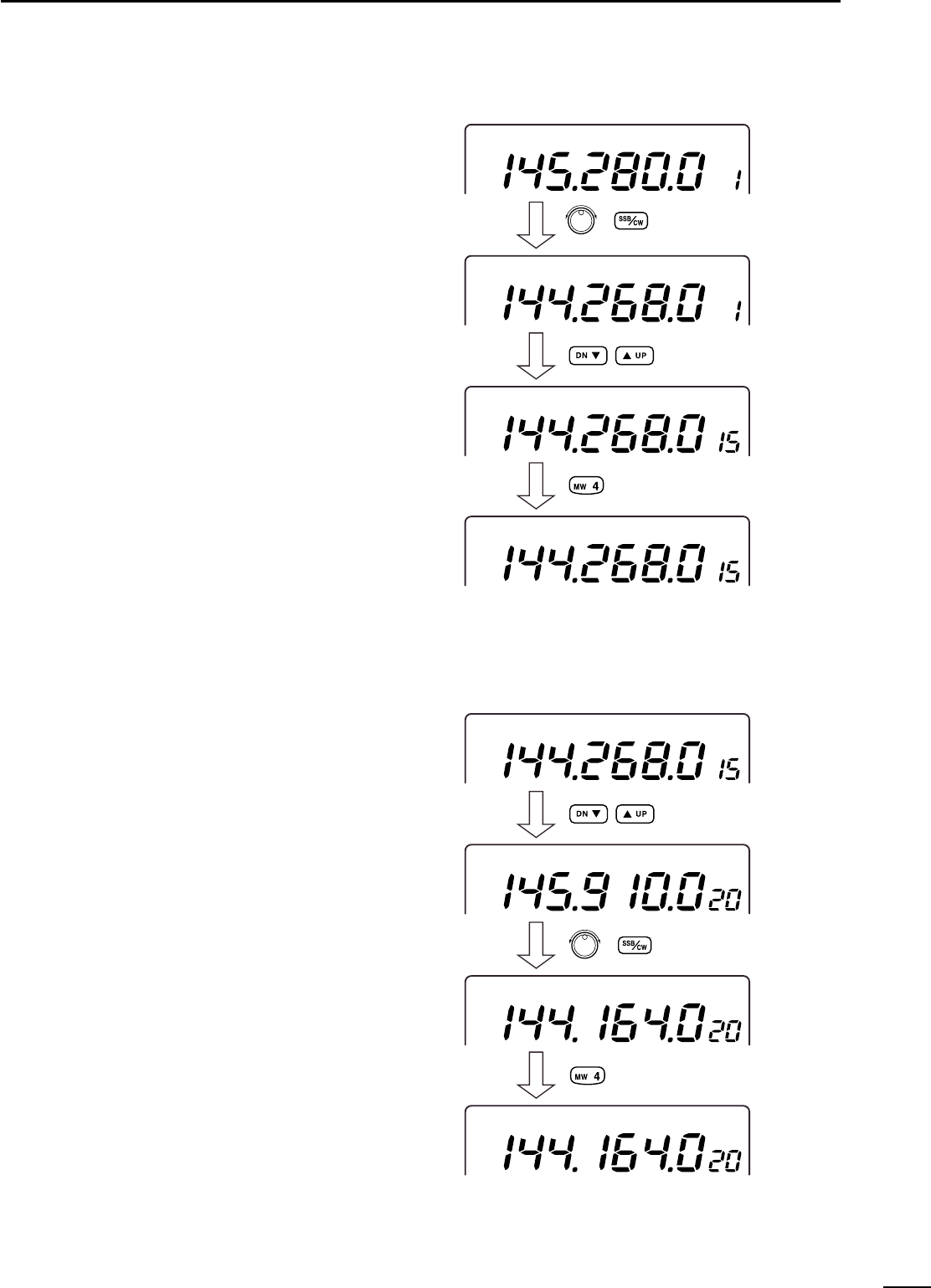
41
6
MEMORY OPERATION
■Programming in VFO mode
Memory channel programming can be performed ei-
ther in VFO mode or in memory mode.
qSet the desired operating frequency and mode in
VFO mode.
•Push [V/M 1] to select VFO mode, if required.
•Tone frequency, offset frequency, etc., can also be pro-
grammed.
•Input the frequency from the keypad
Push [F-INP ENT] ⇒[1] ⇒[4] ⇒[4] ⇒[.] ⇒[2] ⇒[6]
⇒[8] ⇒[F-INP ENT]
wPush [DN▼] or [▲UP] to select the desired mem-
ory channel to be programmed.
ePush [MW 4] for 1 sec. to program the displayed fre-
quency and operating mode into the memory chan-
nel.
To check the programmed contents, push [V/M 1] to
select memory mode.
F
M
VFO A
USBUSB
VFO A
USBUSB
USBUSB
VFO A
VFO A
Select desired memory
channel.
Beep tones sound.
Set desired frequency
and mode.
■Programming in memory
mode
qPush [V/M 1] to select memory mode.
wPush [DN▼] or [▲UP] to select the desired mem-
ory channel to be programmed.
•The tuning dial rotation while pushing [F-INP ENT] also
selects memory channel.
eSet the desired operating frequency and mode in
the memory mode.
•Tone frequency, offset frequency, etc., can also be pro-
grammed.
•Set the desired operating frequency using with the key-
pad when programming into blank channels. The tuning
dial rotation for frequency setting cannot be performed
when a blank channel is selected.
•Input the frequency from the keypad
Push [F-INP ENT] ⇒[1] ⇒[4] ⇒[4] ⇒[.] ⇒[1] ⇒[6]
⇒[4] ⇒[F-INP ENT]
rPush [MW 4] for 1 sec. to program the displayed fre-
quency and operating mode into the memory chan-
nel.
MEMO
F
M
MEMO
USBUSB
MEMO
USBUSB
MEMO
USBUSB
Set desired frequency
and mode.
Beep tones sound.
Select desired memory
channel.
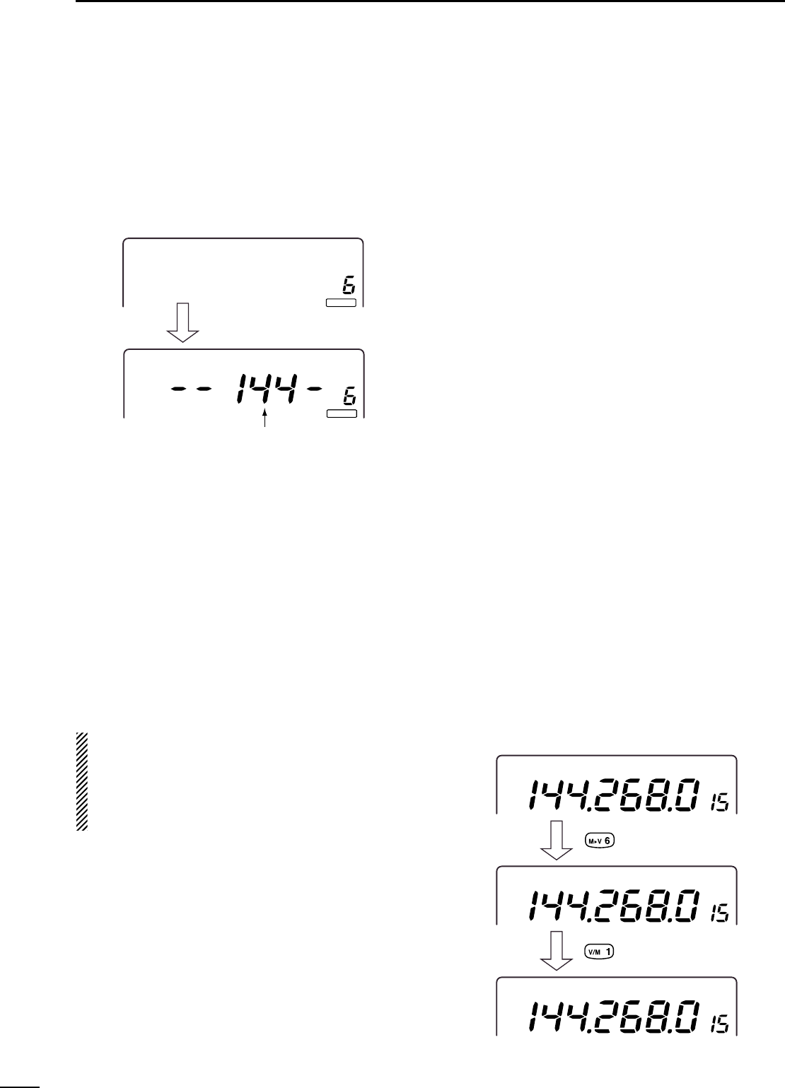
42
6MEMORY OPERATION
■Blank channels
Memory channels 6–99 are blank channels by factory
default. They have no contents programmed.
When a blank channel is selected, the “BLANK”indi-
cator appears and the frequency band is displayed
2 sec. after the selection.
◊Programming a blank channel
qPush [V/M 1] to select VFO mode.
wSet the desired operating frequency, mode, etc.
ePush [MW 4] for 1 sec. to program the memory
channel.
•“BLANK”indicator disappears.
MEMO
BL
ANAN
K
MEMO
BL
ANAN
K
Operating band appears
after 2 sec.
“--430-” appears while in 430 MHz band.
“-1200-” appears while in 1200 MHz band.
■Frequency transferring
The frequency and operating mode in a memory chan-
nel can be transferred to the VFO.
Frequency transferring can be performed in either VFO
mode or memory mode.
◊Transferring in memory mode
This is useful for transferring frequency and operating
mode while operating in memory mode.
When you have changed the frequency or operating
mode in the selected memory channel:
•Displayed frequency and mode are transferred.
•Programmed frequency and mode in the memory
channel are not transferred, and they remain in the
memory channel.
qPush [DN▼] or [▲UP] to select the memory chan-
nel to be transferred in memory mode.
•And, set the frequency or operating mode if required.
wPush [M≈V 6] for 1 sec. to transfer the frequency
and operating mode.
•Displayed frequency and operating mode are transferred
to the VFO.
ePush [V/M 1] to return to VFO mode.
◊Transferring in VFO mode
This is useful for transferring programmed contents to
VFO.
qPush [V/M 1] to select VFO mode.
wPush [DN▼] or [▲UP] to select the memory chan-
nel to be transferred.
•“BLANK”appears if the selected memory channel is a
blank channel. In this case transferring is impossible.
ePush [M≈V 6] for 1 sec. to transfer the frequency
and operating mode.
•Transferred frequency and operating mode appear on
the frequency readout.
MEMO
USBUSB
MEMO
USBUSB
USBUSB
VFO A
Beep tone sounds.
Select VFO mode.
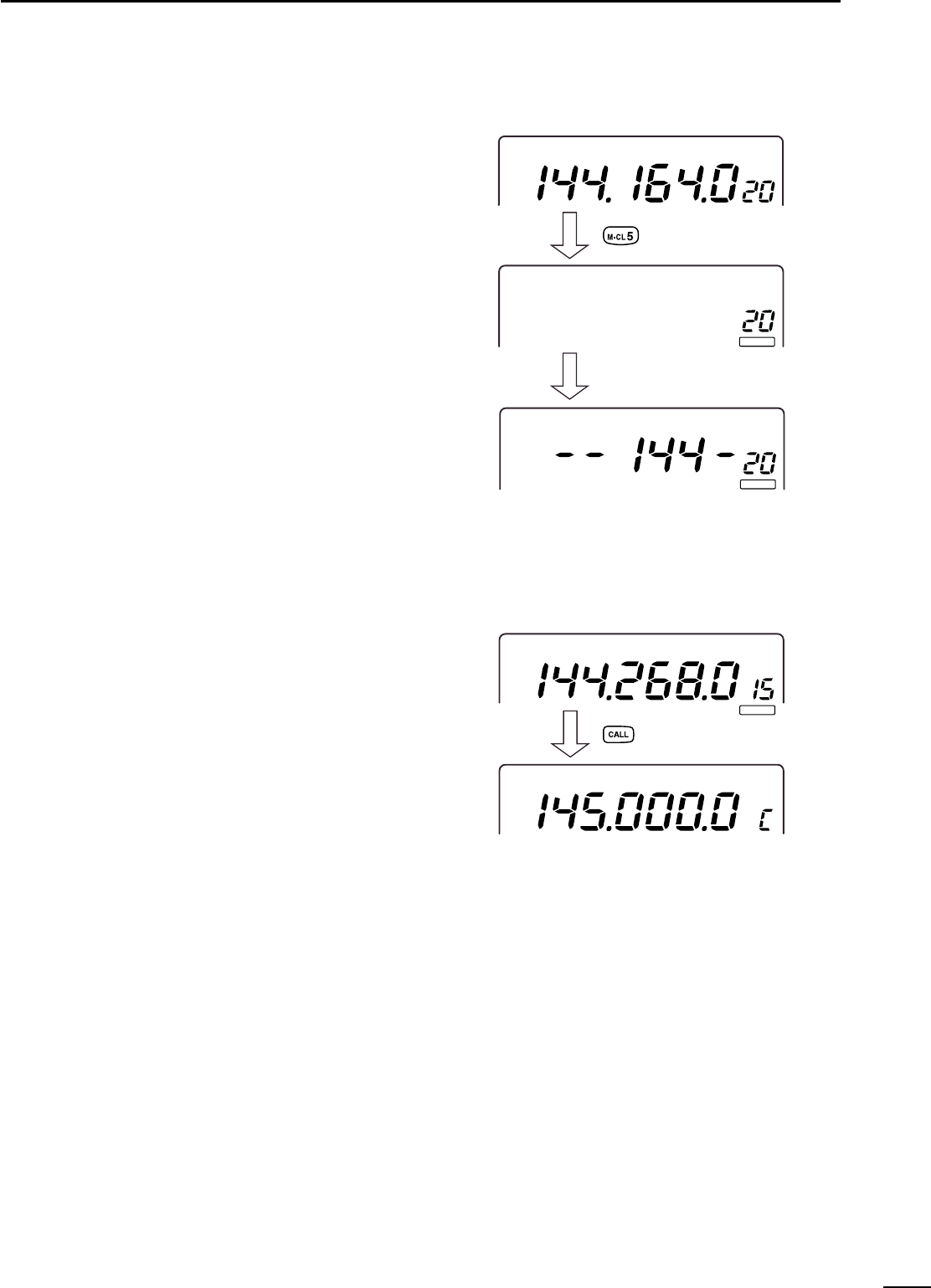
43
6
MEMORY OPERATION
■Memory clearing
Any unnecessary memory channels can be cleared.
The cleared memory channels become blank chan-
nels.
qPush [V/M 1] to select memory mode.
wPush [DN▼] or [▲UP] to select the desired mem-
ory channel to be cleared.
ePush [M-CL 5] for 1 sec. to clear the contents.
•The programmed frequency and operating mode disap-
pear.
•“BLANK”indicator appears.
rTo clear other memory channels, repeat steps w
and e.
MEMO
USBUSB
MEMO
BL
ANAN
K
Operating band appears
after 2 sec.
MEMO
BL
ANAN
K
Beep tone sounds.
■Call channel
The call channel is a one-touch accessible channel for
recalling your most-often-used frequency. The IC-910H
has one call channel for each frequency band.
◊Call up a call channel
qPush [M/S•BAND] or [SUB] to select the desired
frequency band.
wPush [CALL] to select the call channel.
ePush [CALL] or [V/M 1] to return to previous display.
◊Call channel programming
qPush [M/S•BAND] or [SUB] to select the desired
frequency band.
wPush [CALL] to select the call channel.
eEnter the desired frequency using the keypad.
e.g.; When programming 145.8200 MHz.
Push [F-INP ENT] ⇒[1] ⇒[4] ⇒[5] ⇒[.] ⇒[8] ⇒
[2] ⇒[F-INP ENT]
•Select operating mode if required.
rPush [MW 4] for 1 sec. to program the call channel.
◊Transferring call channel contents
qPush [M/S•BAND] or [SUB] to select the desired
frequency band.
wPush [CALL] to select the call channel.
ePush [M≈V 6] for 1 sec. to transfer the call channel
contents.
F
M
USBUSB
VFO A
BL
ANAN
K
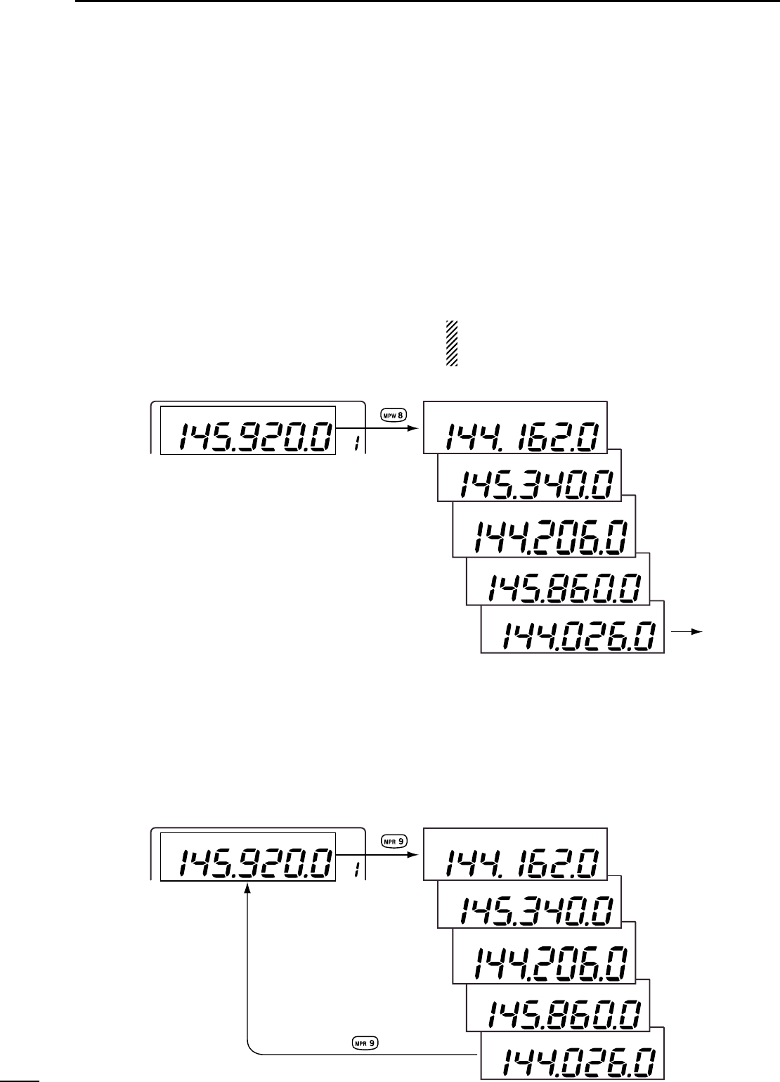
44
6MEMORY OPERATION
■Memo pads
The IC-910H has a memo pad function for each fre-
quency band to store frequency and operating mode
for easy write and recall. The memo pads are separate
from memory channels.
The default number of memo pads is 5, however, this
can be increased to 10 in the memo pad set mode
(p. 64) if desired.
Memo pads are convenient when you want to memo-
rize a frequency and operating mode temporarily, such
as when you find a DX station in a pile-up, or when a
desired station is busy for a long time and you want to
temporarily search for other stations.
Use the transceiver’s memo pads instead of relying on
hastily scribbled notes that are easily misplaced.
◊Writing frequencies and operating
modes into memo pads
You can simply store the accessed readout frequency
and operating mode by pushing [MPW 8].
When you write a 6th (or 11th) frequency and operat-
ing mode, the oldest written frequency and operating
mode are automatically erased to make room for the
new settings.
Each memo pad must have its own unique combi-
nation of frequency and operating mode; memo
pads having identical settings cannot be written.
◊
Calling up a frequency from a memo pad
You can simply call up the desired frequency and op-
erating mode of a memo pad by pushing [MPR 9].
•Both VFO and memory modes can be used.
•The frequency and operating mode are called up, starting
from the most recently written.
C
W
F
M
USB
F
M
USB
F
M
VFO A
VFO or memory mode Memo pad contents
C
W
F
M
USB
F
M
USB
VFO or memory mode Memo pad contents
When [MPW 8] is pushed, “FM 145.9200 MHz”
is programmed and the oldest memo pad is
cleared.
Cleared
F
M
VFO A
7
45
SCANS
■Scan types
Scanning searches for signals automatically and
makes it easier to locate new stations for contact or lis-
tening purposes.The IC-910H has several scan types;
programmed scan, memory scan and mode select
scan.
The scanning operation can be performed indepen-
dently for MAIN and SUB band. And to search a sub-
audible tone frequency for a repeater frequency, a tone
scan is also available.
■Preparation
•Squelch condition
Set the [RF/SQL] control as for regular operation.
•When receiving a signal
•Scan pauses for 10 sec. when receiving a signal, then
resumes.
•When a signal disappears while scan is paused, scan
resumes approx. 3 sec. later.
•Scan resume ON/OFF
You can select the scan to resume or cancel when re-
ceiving a signal, in the scan set mode. Scan resume
ON/OFF must be set before operating a scan. See de-
tails described at right for ON/OFF setting.
•Scan start/stop operation
Push [SCAN .] to start and cancel scanning.
•Scan speed
Scan speed can be selected from 2 levels, high (de-
fault) or low, in the scan set mode. See details de-
scribed at right.
•Setting scan resume condition
qPush [SET] then [SCAN .] to enter the scan set
mode.
wPush [DN▼] or [▲UP] to select the scan resume
item.
•“SC-rES”is displayed.
eRotate the tuning dial to select scan resume condi-
tion from ON and OFF.
•“ON”: scan resumes, “oFF”: scan cancels
•Push [M-CL-5] for 1 sec. to return to the default setting.
rPush [SCAN .] to exit from the scan set mode.
•Setting scan speed
qPush [SET] then [SCAN .] to enter the scan set
mode.
wPush [DN▼] or [▲UP] to select the scan speed
item.
•“SC-SPd”is displayed.
eRotate the tuning dial to select scan resume condi-
tion from HI and Lo.
•Push [M-CL-5] for 1 sec. to return to the default setting.
rPush [SCAN .] to exit from the scan set mode.
MEMORY SCAN
Repeatedly scans all programmed memory channels.
This scan operates in memory mode.
M-CH 1 M-CH 5
M-CH 2 M-CH 3 M-CH 4
M-CH 6
M-CH 7
M-CH 99
Call channels and scan edge channels are not scanned.
Blank
PROGRAMMED SCAN
Repeatedly scans between two scan edge frequencies
(scan edge memory channels 1A/2A/3A and 1b/2b/3b).
This scan operates in VFO mode.
Scan starts from the displayed frequency or the lower
scan edge frequency.
Scan
Scan edge
(1A/2A/3A) Scan edge
(1b/2b/3b)
Jump
MODE SELECT SCAN
Repeatedly scans all selected mode memory channels.
This scan operates in memory mode.
FM FM
USB FM CW
USBFM
FM
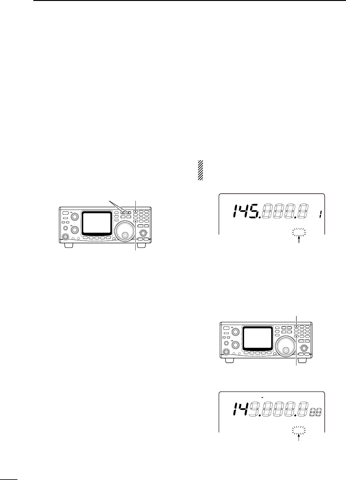
46
7SCANS
■Programmed scan operation
Scans specified frequency range, programmed in the
memory channel 1A/1b, 2A/2b and 3A/3b. Before start-
ing the programmed scan, scan edges should be pro-
grammed in these channels.
◊Selecting scanning range
qPush [M/S•BAND] or [SUB] to select the desired
frequency band to be scanned.
wPush [SET] then [SCAN .] to enter the scan set
mode.
ePush [DN▼] or [▲UP] to select the programmed
scan item.
•“P-SCAn”is displayed.
rRotate the tuning dial to select the desired scanning
range from 1A-1b, 2A-2b and 3A-3b.
•Push [M-CL 5] for 1 sec. to return to the default setting.
tPush [SCAN .] to exit from the scan set mode.
◊Starting the programmed scan
qPush [M/S•BAND] or [SUB] to select the desired
frequency band to be scanned.
wPush [V/M 1] to select VFO mode.
eSelect the desired operating mode.
•The operating mode can also be changed while scan-
ning.
rPush [SCAN .] to start the programmed scan.
•“SCAN”indicator flashes.
•The tuning step setting is used for the scanning step.
•1 kHz or 1 MHz tuning step can also be used as the
scanning step.
tPush [SCAN .] to cancel the scan.
If the same frequency is programmed into the scan
edge memory channel 1A and 1b, 2A and 2b or 3A
and 3b, programmed scan does not start.
F
M
VFO A
60dB
S
C
A
N
S13 5 7920 40
Flashes while scanning
wSelect
mode.
qSelect VFO
mode.
eStart.
rStop.
■Memory scan operation
Scans programmed memory channels only. Blank
channels and programmed scan edge channels
(1A/1b, 2A/2b and 3A/3b) are not scanned.
qPush [M/S•BAND] or [SUB] to select the desired
frequency band to be scanned.
wPush [V/M 1] to select memory mode.
ePush [SCAN .] to start the memory scan.
•“SCAN”indicator flashes.
•Pushing [SPCH•LOCK] for 1 sec. during scan starts
mode select scan and “LOCK”indicator appears. (p. 47)
rPush [SCAN .] to cancel the scan.
MEMO
F
M
USBLSB
C
W
N
A
TT P.AMP AFCN
BF
AGC
60dB
S
C
A
N
S13 5 7920 40
SQ
L
T-
Flashes while scanning
qSelect memory
mode.
wStart.
eStop.
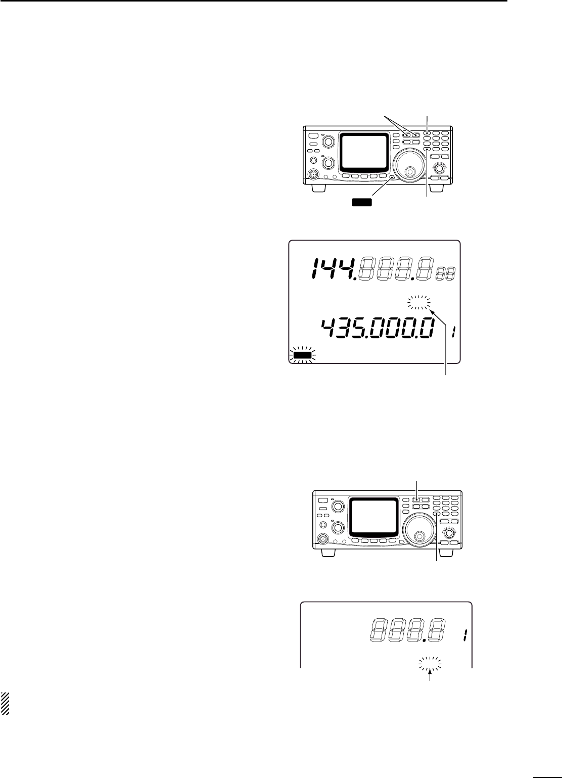
47
7
SCANS
■Mode select scan
Scans the memory channels, desired operating mode
is programmed, only.
qPush [M/S•BAND] or [SUB] to select the desired
frequency band to be scanned.
wPush [V/M 1] to select memory mode.
ePush [SSB/CW] or [FM] to select the desired oper-
ating mode to be scanned.
•The operating mode can also be changed during scan.
rPush [SPCH•LOCK] for 1 sec.
•“LOCK”indicator appears.
tPush [SCAN .] to start the mode select scan.
•“SCAN”indicator flashes.
yPush [SCAN .] to cancel the scan.
MEMO
USBUSB
VFVF
O
A
F
M
L
OCK
S 1 3 5792020 4040 60dB60dB
60dB
S
C
A
N
S13 5 7920 40
Flashes while scanning
wSelect
mode.
qSelect memory
mode.
e appears. rStart.
tStop.
LOCK
■Tone scan
The transceiver can detect a subaudible tone fre-
quency in a received signal. By monitoring a signal that
is being transmitted on a repeater input frequency, you
can determine the tone frequency required to access
the repeater.
qSet the desired frequency or memory channel to be
checked for a tone frequency.
wPush [FM] to select FM mode.
ePush [TONE] or [CALL•T-SQL] for 1 sec. to activate
the subaudible tone.
•“T”or “T-SQL”indicator appears.
rPush [SCAN .] for 1 sec. to start the tone scan.
•“SCAN”indicator flashes while scanning.
•Scan stops when a subaudible tone is detected.
•Scan becomes slower or quicker, respectively when the
noise squelch is open or closed.
tPush [SCAN .] for 1 sec. to cancel the scan.
NOTE: The tone scan automatically changes tone
frequency setting to the detected tone frequency.
F
M
VFO A
60dB
S
C
A
N
S13 5 7920 40
Flashes while scanning
SQ
L
T-
qSelect FM mode.
wStart.
eStop.
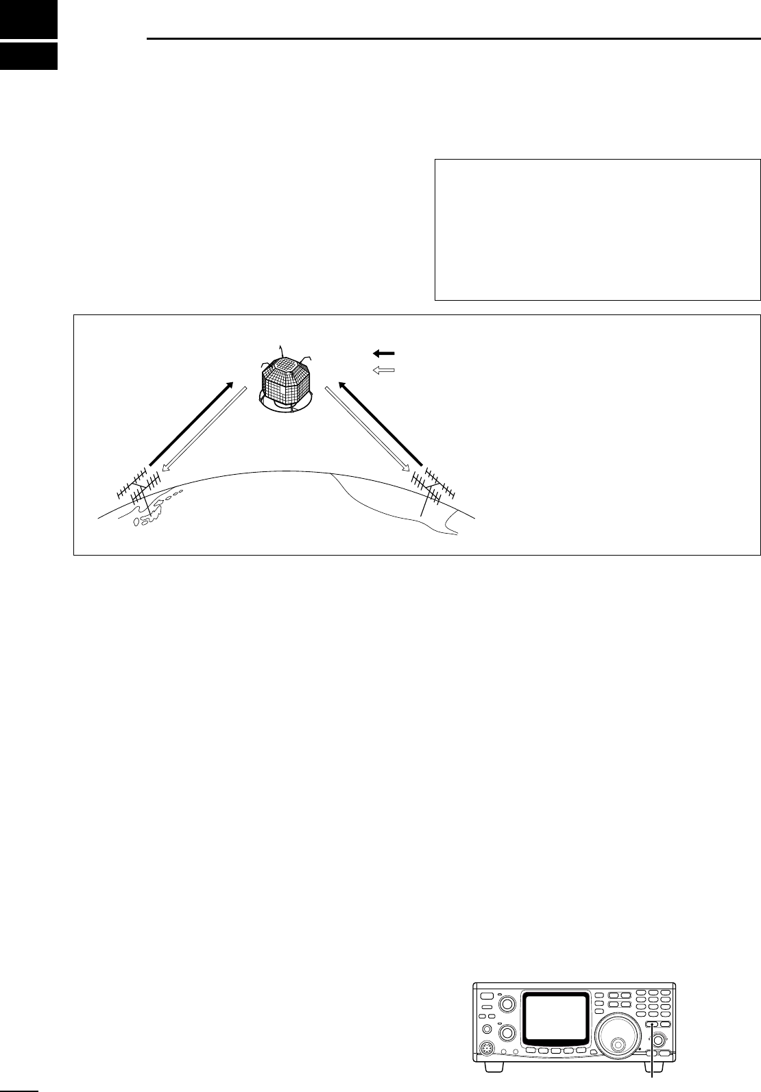
435 MHz
band
435 MHz
band
145 MHz band
145 MHz
band
FUJI 3 (FO-29)
Uplink
Downlink
8
48
SATELLITE OPERATION
■Satellite communications outline
Both satellite mode B (435 MHz uplink, 145 MHz
downlink) and mode J (145 MHz uplink, 435 MHz
downlink) can be operated from the IC-910H, and
mode L can be operated when the optional UX-910
1200 MHz BAND UNIT is installed.
Satellite communications is possible only when a satel-
lite is in view and its transponder is activated.
■Satellite notes
1. NEVER set the output power too high. Too much
power will shorten the satellite’s life.
Set your transmit power so that your downlink signal
level is lower than the beacon’s signal level.
2. Confirm a satellite’s operating mode in advance
through documentation (magazines, etc.) or via ap-
propriate satellite tracking software. In the wrong
mode, you cannot use the satellite even if you re-
ceive its beacon signal.
3. Preamplifiers may be necessary to receive satellite
signals. Optional AG-25, AG-35 and AG-1200 (for
UX-910) are available to use with the IC-910H.
(p. 16)
4. When you use a reverse tracking satellite in SSB
mode, use the LSB for the uplink frequency and
USB for the downlink frequency.
•When using a normal tracking satellite in SSB mode,
use USB for both the uplink and downlink frequencies.
■Entering into the satellite
mode
Operating frequencies in satellite mode can be set
both before and after entering into the satellite mode.
Normal and reverse tracking are available.
◊Transferring the VFO frequency to the
satellite VFO
qSet the downlink frequency (receive) in the MAIN
band.
wSet the uplink frequency (transmit) in the SUB band.
ePush [SATELLITE] for 1 sec. to transfer the fre-
quencies, set in steps qand w, into the satellite
VFO.
•Satellite mode is automatically selected after transfer-
ring.
•“SATL”indicator with either “NOR”or “REV”indicator ap-
pears.
•VFO and memory mode indications are displayed in the
SUB band (lower area) during satellite mode.
[SATELLITE] for 1 sec.
•Mode B operating diagram
[Example]: FUJI 3 (FO-29), Mode B
•Uplink frequency:
145.9000–146.0000MHz
•Downlink frequency:
435.8000–435.9000 MHz
•Tracking direction:
Reverse
•CW beacon frequency:
435.7950 MHz
Orbit information
Orbit information describes satellite location, reach-
ing angles, etc. This information may be available in
ham magazines or organization issues, such as from
ARRL, RSGB handbook, etc.
Appropriate satellite tracking software is also conve-
nient.
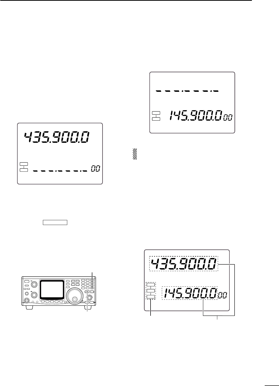
49
8
SATELLITE OPERATION
■Setting the satellite VFO
qPush [SATELLITE] to enter the satellite mode.
•“SATL”indicator with either “NOR”or “REV”indicator ap-
pears.
wPush [V/M 1] to toggle satellite VFO and memory
mode.
•VFO or memory mode indicator is displayed in the SUB
band (lower area).
ePush [SCAN . Â] to enable the downlink frequency
tuning.
•Uplink frequency indication disappears.
•Rotate the tuning dial to set the downlink frequency and
push [SSB/CW] to select the operating mode.
•Push [SCAN . Â] again after the tuning.
rPush [SWP 0 Í] to enable the uplink frequency
tuning.
•Downlink frequency indication disappears.
•Push [SWP 0 Í] again after the tuning.
NOTE: To select the operating mode for the uplink,
push [SUB] to enable the SUB band access.
USBUSB
M
E
MO
L
SB
S
A
T
L
RE
V
S 1 3 5792020 4040 60dB60dB
60dB
S13 5 7920 40
USBUSB
M
E
MO
L
SB
S
A
T
L
RE
V
S 1 3 5792020 4040 60dB60dB
60dB
S13 5 7920 40
■Tracking selection
•Push [F-INP ENT ] for 1 sec. to switch be-
tween normal and reverse tracking.
◊Normal tracking
Both downlink and uplink frequencies increase or de-
crease in the same step simultaneously by tuning dial
rotation.
◊Reverse tracking
The downlink frequency follows the tuning dial rotation,
however, the uplink frequency changes in the reverse
direction to the tuning dial rotation in the same step.
USBUSB
M
E
MO
L
SB
NOR
S
A
T
L
RE
V
S 1 3 5792020 4040 60dB60dB
60dB
S13 5 7920 40
Satellite mode indication Varies simultaneously
[SATELLITE]
[F-INP ENT]
NOR↔REV
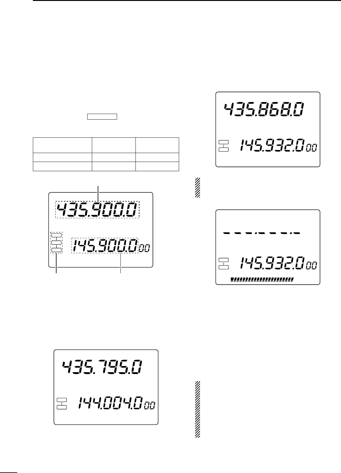
50
8SATELLITE OPERATION
■Preparation
qDecide on a usable satellite.
wConfirm the approximate location of the satellite and
operating mode (e.g. “B,”“J,”etc.) through docu-
mentation (magazine, etc.) or via appropriate satel-
lite tracking software.
eSet the antenna direction for the desired satellite.
rSelect satellite mode on the transceiver.
•Push [SATELLITE].
•Push [F-INP ENT ] for 1 sec. to select track-
ing mode if desired.
tSelect operating mode.
ySet the downlink frequency (MAIN band) to the bea-
con frequency.
•Refer to a ham magazine or book for detailed informa-
tion.
•Adjust the antenna direction so that the S-meter shows
to its strongest level.
•The S-meter level should be noted for transmit power
adjustment during a loop test.
uPerform a loop test.
•Set the downlink frequency (MAIN band) to a vacant fre-
quency within the satellite’s coverage.
•Push [SWP 0 Í] then, set the uplink frequency (SUB
band) while transmitting a single tone such as a whistle
to find your downlink signal and monitor your own signal
correctly. Push [SWP 0 Í] after setting.
NOTE: To avoid excessive power, set the output
power so that the downlink signal strength is lower
than the beacon’s strength.
iSet the desired frequency to begin your satellite
communications.
•Both the downlink and uplink frequencies are changed
simultaneously.
oWhen your downlink audio drifts (Doppler effect),
push [SWP 0 Í] then rotate the tuning dial to ad-
just the uplink frequency (SUB band) only.
Push [SWP 0 Í] again after setting.
•When a particular station’s audio is off frequency, use
the RIT function (push [RIT]).
!0 To exit the satellite operation, push [SATELLITE].
CONVENIENT: As the transceiver has 10 satellite
memory channels, once set, desired satellite fre-
quencies can be recalled instantly.
NOTE: As the downlink (MAIN band) signal is ap-
plied to the SUB band unit in-circuitry in satellite
mode, an optional FL-133
CW NARROW FILTER
is nec-
essary to operate CW-N mode.
USBUSB
M
E
MO
L
SB
S
A
T
L
RE
V
S 1 3 5792020 4040 60dB60dB
60dB
S13 5 7920 40
USBUSB
M
E
MO
L
SB
S
A
T
L
RE
V
S 1 3 5792020 4040 60dB60dB
60dB
S13 5 7920 40
USBUSB
M
E
MO
U
SB
S
A
T
L
RE
V
S 1 3 5792020 4040 60dB60dB
60dB
S13 5 7920 40
USBUSB
M
E
MO
L
SB
NOR
S
A
T
L
RE
V
S 1 3 5792020 4040 60dB60dB
60dB
S13 5 7920 40
Satellite mode indication Uplink (transmit) frequency
Downlink (receive) frequency
NOR↔REV
Satellite Downlink Uplink
(MAIN band) (SUB band)
Reverse tracking type USB (or CW) LSB (or CW)
Normal tracking type USB (or CW) USB (or CW)
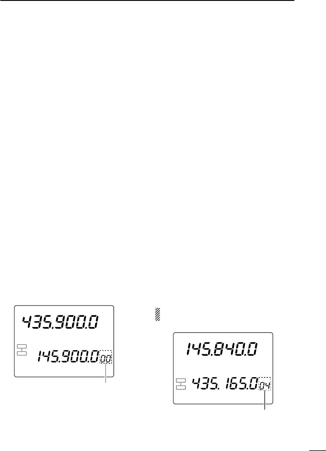
51
8
SATELLITE OPERATION
■Satellite operation
When your own signal can be received with a loop test,
satellite communication can be performed.
qRotate the tuning dial to re-tune the uplink fre-
quency after pushing [SWP 0 Í], when shifting a
frequency with the Doppler effect.
•The downlink frequency readout (MAIN band) disap-
pears.
wRotate the tuning dial to re-tune the downlink fre-
quency after pushing [SCAN . Â], when the operat-
ing station’s signal frequency is shifted.
•RIT function can also be used for downlink frequency
tuning within ±1 kHz range.
■Satellite memory
The IC-910H has 10 satellite memory channels to
memorize both uplink and downlink frequencies and
operating modes, etc.
◊Satellite memory selection
qPush [SATELLITE] to enter the satellite mode.
wPush [V/M 1] to select satellite memory mode.
•“MEMO”indicator and memory channel number are dis-
played beside the uplink frequency (SUB band) indica-
tion.
•Push [V/M 1] again to select satellite VFO.
ePush [DN ▼] or [▲UP] to select the desired satel-
lite mode memory channel.
•The channels 00–09 are selectable.
•By pushing and holding either switch, the satellite mem-
ory channel changes continuously.
◊Satellite memory programming
qSelect the desired satellite memory channel.
•Push [SATELLITE] to enter the satellite mode.
•Push [V/M 1] to select satellite VFO mode.
•Push [DN ▼] or [▲UP] to select the desired satellite
mode memory channel.
wSet the desired downlink frequency to the MAIN
band and uplink frequency to the SUB band, as well
as operating mode.
•Push [SCAN . Â] for downlink tuning, push [SWP 0 Í]
for uplink frequency tuning.
•Push [SUB] before the operating mode selection when
selecting operating mode for the uplink.
ePush [MW 4] for 1 sec. to program the set contents
to the satellite memory channel.
•3 beep tones sound.
NOTE: Tracking selection, normal or reverse, is not
programmed in the satellite memory channels.
USBUSB
M
E
MO
L
SB
S
A
T
L
RE
V
S 1 3 5792020 4040 60dB60dB
60dB
S13 5 7920 40
Select the desired
satellite memory
USBUSB
M
E
MO
L
SB
NOR
S
A
T
L
S 1 3 5792020 4040 60dB60dB
60dB
S13 5 7920 40
Satellite memory
indication
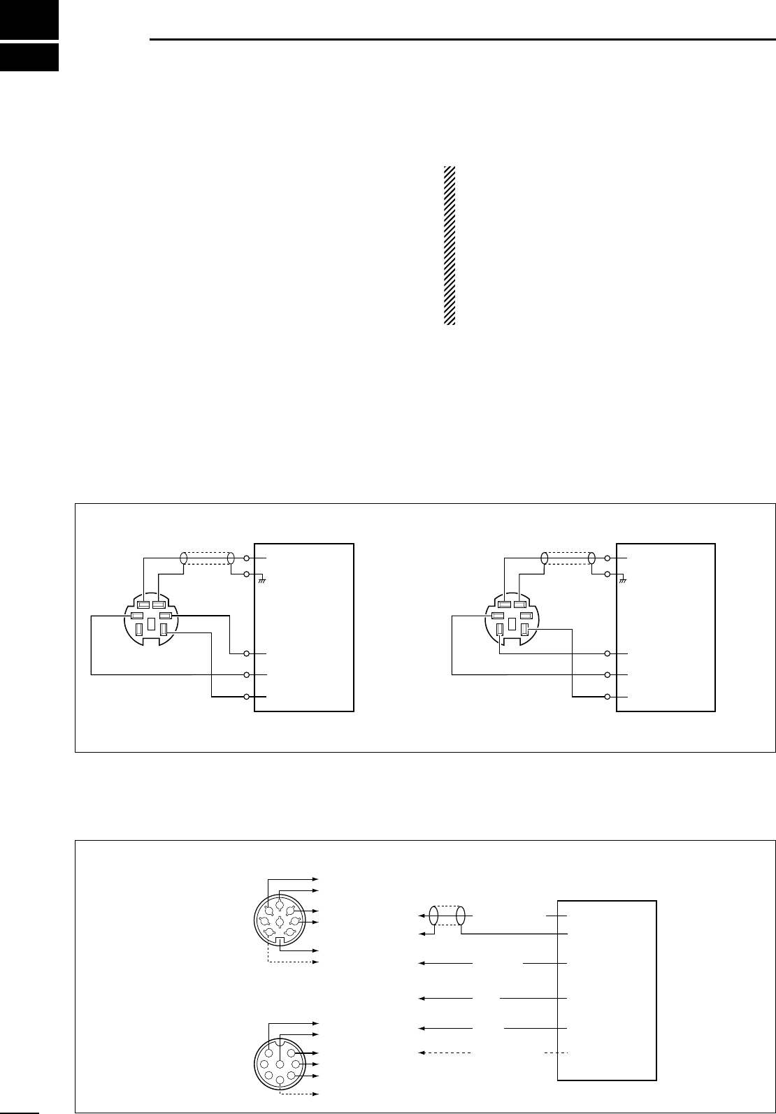
9
52
DATA COMMUNICATION
■Connections for AFSK
◊Connections via [DATA] socket
Use FM mode for 9600 bps operation.
Use SSB or FM mode for 1200 bps operation.
◊Connections via [ACC(1)] socket or [MIC] connector
Use FM mode for 9600 bps operation.
Use SSB or FM mode for 1200 bps operation.
q
DATA IN
SQL*
PTT
RX AUDIO
GND
TX AUDIO
TNC
w
GND
e
PTT r
DATA OUT
Shielding cable
q
DATA IN
SQL*
PTT
RX AUDIO
GND
TX AUDIO
TNC
w
GND
e
PTT y
SQ*
t
AF OUT
Shielding cable
•9600 bps connection •1200 bps connection
* Connect the SQL line when required.
[DATA] socket
(Rear panel view) [DATA] socket
(Rear panel view)
* Connect the SQL line when required.
y
SQ*
1
2
345
6
7
8
A
B
C
D
E
F
*
1
2
3
45
67
8
A
B
C
D
E
F
*
•Connection via [ACC(1)] connector
•Connection via [MIC] connector
TNC
* Connect the SQL line when required.
(Rear panel
view)
(Front panel
view)
A
B
C
D
F
E
AFSK output
AF input
PTT
GND
Squelch input SQL*
PTT
RX AUDIO
(1200 bps)
GND
GND
TX AUDIO
■Functions for AFSK
The IC-910H does not have an FSK mode for RTTY,
AMTOR, PACKET, etc., however, you can operate
these using AFSK in SSB or FM mode.
The transceiver accepts data speed of up to 9600 bps.
When using 9600 bps, set the transceiver to the 9600
bps data mode using the general set mode. (p. 57)
When operating AFSK, connect external equipment to
the DATA (MAIN or SUB) or ACC socket on the rear
panel, or to the microphone connector on the front
panel as in the diagram below.
OPERATION NOTES FOR 9600 bps
•Set the transceiver to 9600 bps data mode.
-See p. 57.
•Set AFSK/GMSK output level of the terminal unit to
0.4 V p-p (0.2 V rms).
-When exceeding 0.5 V p-p (0.25 V rms), the trans-
ceiver’s modulation limiter stops modulation.
-At this time, the [RX/TX] indicator’s brightness fades.
•AF output from the transceiver is continuous and is
not cut by the squelch circuit.

53
9
DATA COMMUNICATION
■Operating mode notes
Use FM mode for 9600 bps operation.
Use SSB or FM mode for 1200 bps operation.
■Operating frequency notes
◊Operating notes for RTTY and AMTOR
RTTY or AMTOR operating frequency in LSB mode
differs from the displayed frequency.
[Your operating freq.] = [Displayed freq.] – 2125 Hz
(when the frequencies of the RTTY demodulator in
your TNC or TU are — mark = 2125 Hz and space =
2295 Hz).
◊Operating notes for PACKET
PACKET operating frequency in LSB mode differs from
the displayed frequency.
[Your operating freq.] = [Displayed freq.] – 2125 Hz
(when the frequencies of the PACKET demodulator in
your TNC are — 2125 Hz/2315 Hz).
◊Frequency setting example for AFSK
-When operating RTTY at 144.090 MHz:
Set “LSB 144.092125 MHz”(if you use mark=2125 Hz
and space=2295 Hz).
-When operating PACKET at 144.110 MHz:
Set “LSB 144.112215 MHz”(if you use
2115 Hz/2315 Hz).
■AFSK operation
Connect external equipment to either the [DATA]
(MAIN or SUB) or [ACC(1)] socket as described on the
previous page. Set the ACC socket using the general
set mode in advance when you operate via the ACC
socket. (See below.)
qPush [M/S•BAND] to select the desired frequency
band.
wPush [FM] or [SSB/CW] to select the desired oper-
ating mode.
•LSB is normally used.
•FM is used for PACKET.
eAdjust the audio output level with [AF] control.
•Use [RF/SQL] when required.
rAdjust the desired RF output power.
•When using the [MIC] connector for external equipment
connection, the [MIC GAIN] control should be adjusted.
tSelect operating mode.
yControl the transceiver from the connected PC or
TNC (TU).
IMPORTANT:
•Remove the microphone from the [MIC] connector
when operating below 1200 bps rate to protect
from noise coming from the microphone.
•During 9600 bps rate operation, noise signals from
the microphone may not effect PACKET signals.
However, PACKET signal transmission is inter-
rupted when [PTT] is pushed.
•Remove the ACC plug, or turn the TNC power OFF
during phone operation (SSB or FM). The modula-
tion input from the [ACC(1)] socket is always ap-
plied to the modulation circuit.
◊Connections via front panel
When connecting a TNC or Scan converter, etc. to the
[MIC] connector, [MIC GAIN] and [AF] adjustments are
required.The [MIC] connector accepts up to 1200 bps.
Use SSB or FM mode for operation.
[MIC GAIN] and [AF] control adjustments are re-
quired.
qSelect
band.
wSelect desired
mode.
eAdjust for max.
detected level.

54
9DATA COMMUNICATION
■Setting the ACC socket
When operating AFSK, set the specifications of the
ACC socket to fit your TNC or scan converter in ad-
vance.
qPush [SET] for 1 sec. to enter the set mode.
wPush [DN ▼] or [▲UP] to select the 9600 bps data
mode setting item, then rotate the tuning dial to turn
the 9600 bps rate ON and OFF
Push [SWP 0] again after setting.
•“9600”is displayed.
•9600 bps data rate is selected when ON, and a slower
data rate is selected when OFF is selected.
•Push [M-CL 5] for 1 sec to return to the default setting.
ePush [▲UP] to select ACC socket pins 5 and 6 set-
ting item, then rotate the tuning dial to select from
“nor”(normal) and “Sub”(sub).
•“ACC P5.6”is displayed.
•When “nor”(normal) is selected, the ACC socket (pins 5
and 6) outputs MAIN band signals. When “Sub”is se-
lected, the ACC socket outputs SUB band signals.
•Push [M-CL 5] for 1 sec to return to the default setting.
NOTE: Select “nor”(normal) when operating data
mode in satellite mode.
rPush [▲UP] to select the modulation signal input
level setting item, then rotate the tuning dial to se-
lect from “HI”and “Lo”(sub).
•“ACC.t-AF”is displayed.
•HI: 200 mV rms, Lo: 2 mV rms
•Push [M-CL 5] for 1 sec to return to the default setting.
•This setting is ignored when 9600 bps data mode (w) is
selected and 1.0 V p-p is set as a fixed value.
tPush [SET] to exit from the set mode.
◊Adjusting the transmit signal output
from the TNC
When setting the data transmission speed to 9600
bps, the data signal coming from the TNC is applied
exclusively to the internal limiter circuitry to control the
transmission.
NEVER apply data levels from the TNC of over
0.6 V p-p, otherwise the transceiver automatically
cancels the transmission.
1. When using a level meter or synchroscope, ad-
just the TX audio output level (DATA IN level)
from the TNC as follows.
0.4 V p-p (0.2 V rms): recommended level
0.2–0.5 V p-p (0.1–0.25 V rms): acceptable level
2. When NOT using a measurement device.
qConnect the transceiver to a TNC.
wEnter a test mode (“CAL”, etc.) to the TNC, then
transmit some test data.
eWhen the transceiver fails to transmit the test
data or transmits sporadically (TX indicator does
not appear or flashes):
-Decrease the TNC output level until the transmit
indicator lights continuously.
When transmission is not successful even though
the TX indicator lights continuously:
-Increase the TNC output level.
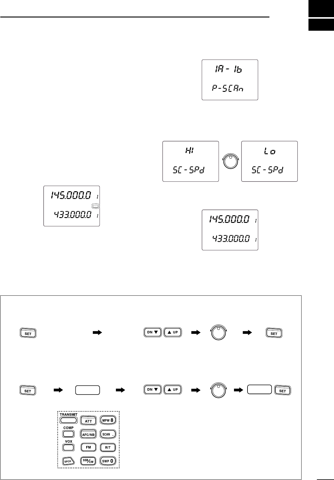
10
55
SET MODE
■Set mode description
Set mode is used for programming infrequently
changed values or conditions of functions. The
IC-910H has a regular set mode and additional 12 in-
dependent set modes for simple condition changing.
◊Set mode operation
qPush [SET] for 1 sec. to enter the general set mode.
wPush [DN Z] or [UP Y] to select the desired item.
eSet the desired condition using the tuning dial.
•Push [M-CL 5] for 1 sec. to select a default condition or
value.
rPush [SET] to exit the set mode.
◊Independent set mode operation
qPush [SET].
wPush 1 of following switches/keys to enter the inde-
pendent set mode.
[SPCH], [FM], [SSB/CW], [SCAN], [MPW], [COMP],
[VOX], [TRANSMIT], [NR], [RIT], [ATT], [SWP]
ePush [DN Z] or [UP Y] to select the desired item.
rSet the desired condition using the tuning dial.
•Push [M-CL 5] for 1 sec. to select a default condition or
value.
tPush the applicable switch, pushed in step w, or
[SET] to exit the set mode.
F
M
VFO A
VF
O
A
F
M
S 1 3 5792020 4040 60dB60dB
S13 5 7920 40
60dB60dB
S
C
A
N
S
C
A
N
S
C
A
N
F
M
VFO A
VF
O
A
S
E
T
F
M
S 1 3 5792020 4040 60dB60dB
S13 5 7920 40
60dB60dB
qw ert
Tuning dial
Exit set mode.
Push applicable key
applicable
Independent
set mode
appears. Select condition.
Push applicable
key or [SET] key.
Push [SET] momentarily.
applicable keys
Select set mode item.
q
Push [SET] for 1 sec. General set mode appears.
wer
Tuning dial
Exit set mode.Select condition.
Push applicable
key or [SET] key.
Select set mode item.
•SET MODE FLOW CHART
applicable
■General set mode
56
10 SET MODE
Display backlight brightness
Adjust backlight brightness for the function display to
the desired level within 0 (dark) to 100 (bright) range.
Beep tone
Adjust key touch beep output level to the desired level
within 0 (no output) to 100 (max. output) range.
RF/SQL control assignment
Assign [RF/SQL] control function from rF/SqL, Auto
and SqL.
•rF/SqL: RF gain and squelch controls are combined
for SSB/CW mode. Acts as squelch control
for FM mode.
•Auto : Acts as either an RF gain or squelch control
depending on operating mode.
•SqL : Acts as squelch control for all modes. RF
gain is set to maximum level in this setting.
Peak hold function
Turn the S-meter peak hold function ON or OFF.
The peak level is indicated for approx. 0.5 sec. when
this function is activated.
57
10
SET MODE
Microphone UP/DN speed
Select continuous changing speed with microphone’s
[UP]/[DN] operation from high and low.
Headphone audio
Switch the audio output separation capability for the
headphones ON and OFF.
•on :The MAIN and SUB band audio is sepa-
rated in right (MAIN) and left (SUB) chan-
nels when using stereo headphones.
•oFF : The MAIN and SUB band audio is mixed.
Fine tuning indication
Turn the fine tuning indication (10 and 1 Hz digit indi-
cation) during the tuning dial rotation ON and OFF.
Auto TS function
Turn the auto TS function ON and OFF.
This function temporarily changes tuning step when
rotating the tuning dial quickly.
The auto TS function automatically selects a 10 or
50 Hz tuning step, when 1 or 10 Hz tuning step is
used for regular operation, respectively.
9600 bps data transmission
Turn the 9600 bps data transmission capability ON
and OFF.
•on : For 9600 bps data transmission.
•oFF : For the regular audio (or slower data) trans-
mission only.
96009600
Tuning step selection HI Lo
Below 1 kHz 50 steps/sec. 25 steps/sec.
Above 1 kHz below 1 MHz 20 steps/sec. 10 steps/sec.
1 MHz or Memory Channel
5 steps/sec. 2.5 steps/sec.
ACC socket Pin 5 and Pin 6
Select the band for output signals from the ACC
socket pins 5 (AF) and 6 (SQL) from normal and sub.
•nor : Outputs MAIN band’s signals.
•Sub : Outputs SUB band’s signals.
58
10 SET MODE
ACC socket Pin 8
Assign the ACC socket pin 8 action/connection from
ALC and microphone up/down.
•ALC : Inputs ALC signal.
•ud : Inputs up/down signals from the microphone.
ACC socket Pin 4/DATA socket Pin 1
Select modulation signal input level from high and
low.
•HI : High modulation signal level (200 mV rms)
•Lo : Low modulation signal level (2 mV rms)
ACC socket Pin 3 for 144 MHz band
Switch the SEND signal output for 144 MHz band op-
eration ON and OFF.
ACC socket Pin 3 for 430(440) MHz band
Switch the SEND signal output for 430(440) MHz
band operation ON and OFF.
ACC socket Pin 3 for 1200 MHz band
Switch the SEND signal output for 1200 MHz band
operation ON and OFF.
Preamplifier controller for 144 MHz
Switch the preamplifier control capability ON and
OFF. When using the optional AG-25, ON must be se-
lected. Otherwise, the preamplifier is never activated.
DO NOT connect any equipment, such as an SWR
or power meter, between the transceiver and pre-
amplifier. In such case, the preamplifier may not ac-
tivate properly.
P.AMP P.AMP
59
10
SET MODE
Preamplifier controller for 430(440) MHz
Switch the preamplifier control capability ON and
OFF. When using the optional AG-35, ON must be se-
lected. Otherwise, the preamplifier is never activated.
DO NOT connect any equipment, such as an SWR
or power meter, between the transceiver and pre-
amplifier. In such case, the preamplifier may not ac-
tivate properly.
P.AMP P.AMP
Preamplifier controller for 1200 MHz
Switch the preamplifier control capability ON and
OFF. When using the optional AG-1200, ON must be
selected. Otherwise, the preamplifier is never acti-
vated.
DO NOT connect any equipment, such as an SWR
or power meter, between the transceiver and pre-
amplifier. In such case, the preamplifier may not ac-
tivate properly.
P.AMP P.AMP
CI-V address
To distinguish between equipment, each CI-V trans-
ceiver has its own Icom standard address in hexa-
decimal code.The IC-910H’s address is 60H.
When 2 or more IC-910Hs are connected to an op-
tional CT-17
CI
-
V LEVEL CONVERTER
, select a different
address for each IC-910H in the range 01H to 7FH.
CI-V baud rate
Select transfer rate for CI-V remote control from Auto,
300, 1200, 4800, 9600 and 19200 bps.
CI-V transceive
Transceive operation is possible with the IC-910H
connected to other Icom transceivers or receivers.
When “on”is selected, changing the operating fre-
quency, operating mode, etc. on the IC-910H auto-
matically changes those of connected transceivers (or
receivers) and vice versa.
60
10 SET MODE
■FM set mode
Offset frequency for 144 MHz
Set the offset frequency for duplex (repeater) opera-
tion within 0–10.00000 MHz range.
This item is displayed when the 144 MHz band is ac-
cessed, including the SUB band access capability.
•Default value: 0.6000
F
M
Offset frequency for 430(440) MHz
Set the offset frequency for duplex (repeater) opera-
tion within 0–10.00000 MHz range.
This item is displayed when the 430(440) MHz band
is accessed, including the SUB band access capabil-
ity.
•Default value: 5.0000
F
M
Offset frequency for 1200 MHz
Set the offset frequency for duplex (repeater) opera-
tion within 0–100.00000 MHz range.
This item is displayed when the 1200 MHz band is ac-
cessed, including the SUB band access capability.
•Default value: 20.0000
F
M
Tone encoder frequency for 144 MHz
(non-European versions)
Select tone encoder frequency for accessing a re-
peater, etc. from one of 50 available tone frequencies.
This item is displayed when the 144 MHz band is ac-
cessed, including the SUB band access capability.
•Default value: 88.5
F
M
T
Tone encoder frequency for 430(440) MHz
(non-European versions)
Select tone encoder frequency for accessing a re-
peater, etc. from one of 50 available tone frequencies.
This item is displayed when the 430(440) MHz band is
accessed, including the SUB band access capability.
•Default value: 88.5
F
M
T
Tone encoder frequency for 1200 MHz
(non-European versions)
Select tone encoder frequency for accessing a re-
peater, etc. from one of 50 available tone frequencies.
This item is displayed when the 1200 MHz band is ac-
cessed, including the SUB band access capability.
•Default value: 88.5
F
M
T
61
10
SET MODE
Tone squelch frequency for 144 MHz
Select tone squelch frequency from one of 50 avail-
able tone frequencies.
This item is displayed when the 144 MHz band is ac-
cessed, including the SUB band access capability.
•Default value: 88.5
F
M
-SQSQ
L
T
Tone squelch frequency for 430(440) MHz
Select tone squelch frequency from one of 50 avail-
able tone frequencies.
This item is displayed when the 430(440) MHz band
is accessed, including the SUB band access capabil-
ity.
•Default value: 88.5
F
M
-SQSQ
L
T
Tone squelch frequency for 1200 MHz
Select tone squelch frequency from one of 50 avail-
able tone frequencies.
This item is displayed when the 1200 MHz band is ac-
cessed, including the SUB band access capability.
•Default value: 88.5
F
M
-SQSQ
L
T
One-touch repeater shift direction
(non-European versions)
Select shift direction for one-touch repeater function
from DUP– and DUP+.
DUPDUP
F
M
DUPDUP
F
M
Auto repeater function
(U.S.A. and Korea versions)
Turn the auto repeater function ON and OFF.
To activate the auto repeater function, ON must be
selected in this setting after programming the auto re-
peater frequency range. (p. 34)
U.S.A. version:
•“on1”Activates duplex only.
•“on2”Activates duplex and tone.
•“oFF”Auto repeater function is turned OFF.
Korea version:
•“ON”Activates duplex and tone.
•“OFF”Auto repeater function is turned OFF.
F
M
F
M
FM center indicator
Turn the FM center indication ON and OFF.
When the indication is turned ON and the received
signal is off-center in FM mode, the receive indicator
(green) flashes.
F
M
F
M
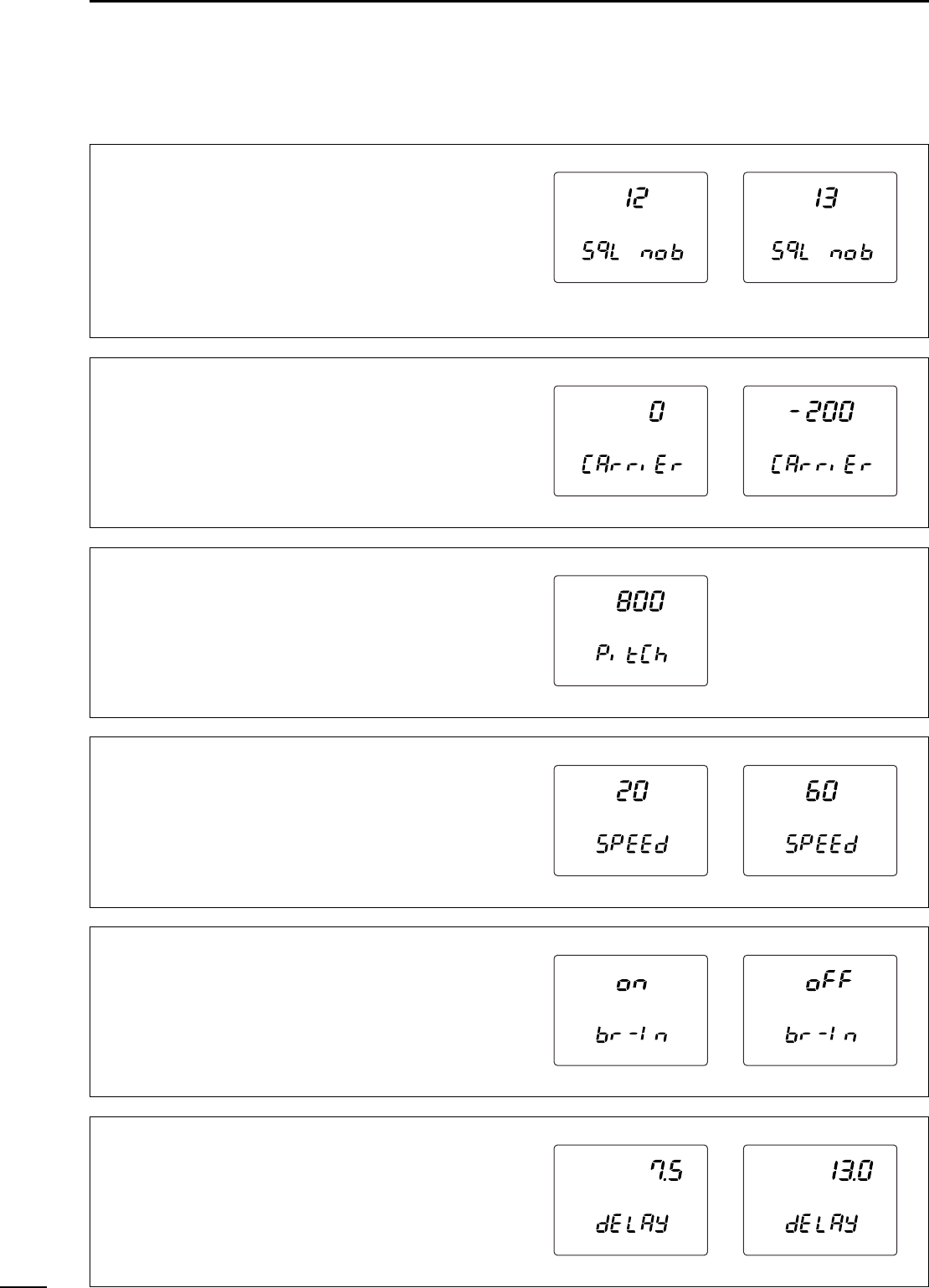
62
10 SET MODE
■SSB/CW set mode
Squelch threshold
Select the squelch threshold level from 12 and 13 o’-
clock.
•12 : The squelch closes around the 12 o’clock po-
sition of the [SQL] control.
•13 : The squelch closes around the 13 o’clock po-
sition of the [SQL] control.
Carrier frequency
Adjust the carrier frequency for SSB (USB/LSB)
mode operation within –200 to +200 Hz range in
10 Hz steps.
L
SB
U
SB
L
SB
U
SB
CW pitch frequency
Adjust the CW pitch frequency within 300 to 900 Hz
range in 10 Hz steps.
CW
CW keying speed adjustment
Adjust the built-in electric keyer keying speed to the
desired level within 6 to 60 WPM range.
CW CW
Semi break-in
Turn the semi break-in function ON and OFF.
CW CW
CW break-in delay
Adjust the CW break-in delay time to the desired level
within 2.0 to 13.0 sec. range in 0.1 sec. steps.
CW CW
63
10
SET MODE
AF control relation
Turn the relation of [AF] control for CW side tone out-
put level ON and OFF.
•on : CW side tone output level is adjustable via
[AF] control adjustment.
•oFF : CW side tone output level is fixed regardless
of [AF] control setting.
CW CW
CW side tone output level
Adjust the CW side tone output to the desired level
within 0 (no output) to 100 (maximum output) range.
CW CW
Key type
Select the key type from normal, reverse, bug, OFF
and microphone [UP]/[DN].
•n : Use built-in electronic keyer.
•r : Use built-in electronic keyer with reversed
polarity.
•buG : Use built-in electronic keyer as bug key.
•oFF : Use external electronic keyer or straight key.
•ud : Use microphone’s [UP]/[DN] as a paddle.
CW CW
CW dot-dash ratio
Adjust the CW dot-dash ratio to the desired level
within 1:1:2.8 to 1:1:4.5 range.
CW
C/N type for 1200 MHz
Select the C/N type for the 1200 MHz band operation
from type 1 and 2.
•tyPE 1 : Provides better characteristics for nearby in-
terference in FM mode operation.
•tyPE 2 : Provides lower noise level just around the
signal in SSB/CW mode operation.
This item is displayed only when the optional UX-910
is installed.
USBUSBLSBLSB
C
W
F
M
64
10 SET MODE
■Scan set mode
■Memo pad set mode
Programmed scanning range
Select the programmed scan range from 1A-1b, 2A-
2b and 3A-3b.
•1A-1b : Scans within the range programmed in the
memory channel 1A and 1b.
•2A-2b : Scans within the range programmed in the
memory channel 2A and 2b.
•3A-3b : Scans within the range programmed in the
memory channel 3A and 3b.
S
C
A
N
S
C
A
N
Scan resume condition
Select the scan resume condition from ON and OFF.
•on : Scan resumes.
•oFF : Scan cancels when a signal is received.
S
C
A
N
S
C
A
N
Number of memo pad channels
Select the number of memo pad channels available
from 5 and 10.
•5 : 5 memo pad channels can be used.
•10 : 10 memo pad channels can be used.
■Compressor set mode
Compression level
Adjust the compression level for the speech com-
pressor to the desired level within 0–100% range.
COMPMP
Scanning speed
Select the scanning speed from high and low.
S
C
A
N
S
C
A
N
Scan type HI Lo
Memory scan (Mode select)
20 CH/sec. 10 CH/sec.
Prog. scan (TS<1 kHz) 50 steps/sec. 25 steps/sec.
Prog. scan (TS>1 kHz) 20 steps/sec. 10 steps/sec.
Tone scan 20 steps/sec. 10 steps/sec.
65
10
SET MODE
■VOX set mode
VOX sensitivity
Adjust the VOX sensitivity within 0–100% range.
V
O
X
VOX delay time
Adjust the transmit-to-receive switching delay to the
desired level within 0.0 sec. to 2.0 sec. range in
0.1 sec. steps.
V
O
X
■Attenuator set mode
Attenuation level for 144 MHz
Adjust the attenuation level to the desired level within
0–100% range for the 144 MH
Z
band operation.
Attenuation level for 430(440) MHz
Adjust the attenuation level to the desired level within
0–100% range for the 430(440) MH
Z
band operation.
Anti VOX
Adjust the anti VOX gain within 0–100% range.
V
O
X
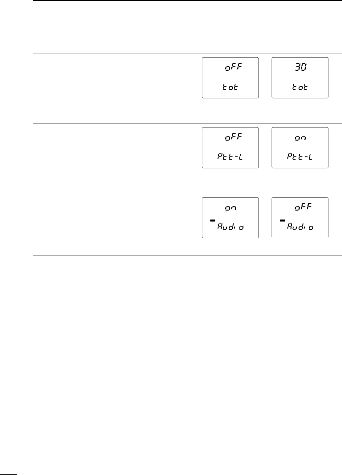
66
10 SET MODE
■Transmit set mode
Time-out timer
Select the time period for the time-out timer function
from OFF, 3, 5, 10, 20 and 30 min.
PTT lock
Turn the transmission inhibit capability ON and OFF.
Any control for transmission is inhibited when this
item is ON.
SUB band mute
Turn the SUB band audio mute function ON and OFF.
The SUB band audio is muted while transmitting
when this function is turned ON.
S
U
B
S
U
B
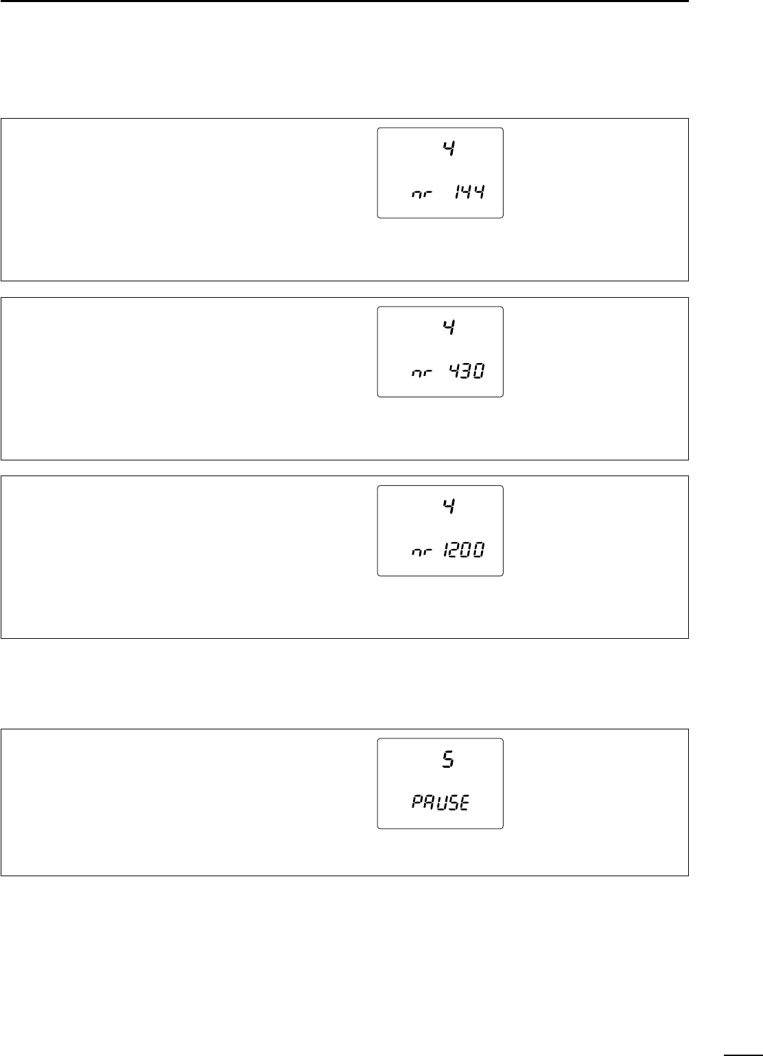
Noise reduction level for 1200 MHz
Adjust the noise reduction level to the desired level
within 0–15 for the 1200 MHz band operation.
Adjust it to the level that noise signals are reduced,
and received audio has no distortion.
This item is displayed only when the optional UT-106
is installed.
N
R
Sweeping interval
Select the sweeping interval for the simple band
scope function from 3, 5 and 10 sec.
S
W
P
67
10
SET MODE
■NR set mode
Noise reduction level for 144 MHz
Adjust the noise reduction level to the desired level
within 0–15 for the 144 MHz band operation.
Adjust it to the level that noise signals are reduced,
and received audio has no distortion.
This item is displayed only when the optional UT-106
is installed.
N
R
Noise reduction level for 430(440) MHz
Adjust the noise reduction level to the desired level
within 0–15 for the 430(440) MHz band operation.
Adjust it to the level that noise signals are reduced,
and received audio has no distortion.
This item is displayed only when the optional UT-106
is installed.
N
R
■SWP set mode
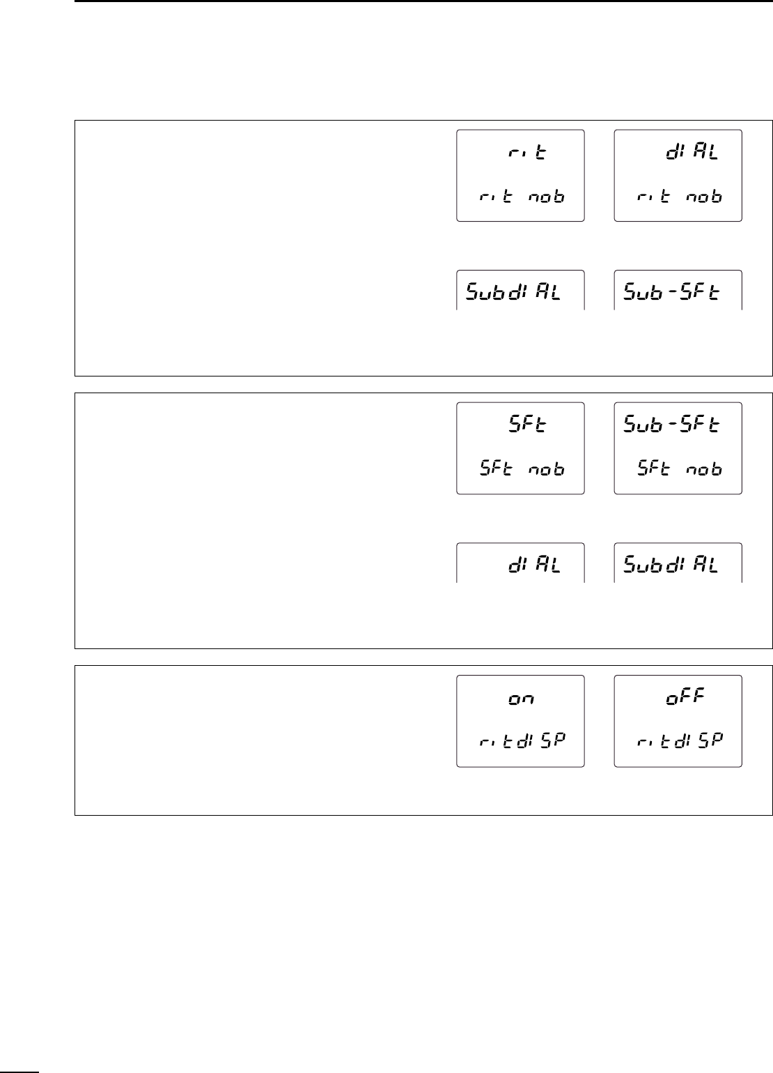
■RIT/SHIFT set mode
68
10 SET MODE
RIT control assignment
Assign [RIT] control function from rit, dIAL, SubdIAL
and Sub-SFt.
•rit : [RIT] control functions as RIT control.
•dIAL : [RIT] control functions as tuning dial for
MAIN band.
•SubdIAL : [RIT] control functions as tuning dial for
SUB band.
•Sub-SFt : [RIT] control functions as IF shift control
for SUB band.
SHIFT control assignment
Assign [SHIFT] control function from SFt, Sub-SFt,
dIAL and SubdIAL.
•SFt : [SHIFT] control functions as IF shift con-
trol.
•Sub-SFt : [SHIFT] control functions as IF shift con-
trol for SUB band.
•dIAL : [SHIFT] control functions as tuning dial
for MAIN band.
•SubdIAL : [SHIFT] control functions as tuning dial
for SUB band.
RIT indication
Turn the RIT adjusting value indication ON and OFF.
The value is displayed while adjusting when this func-
tion is turned ON.
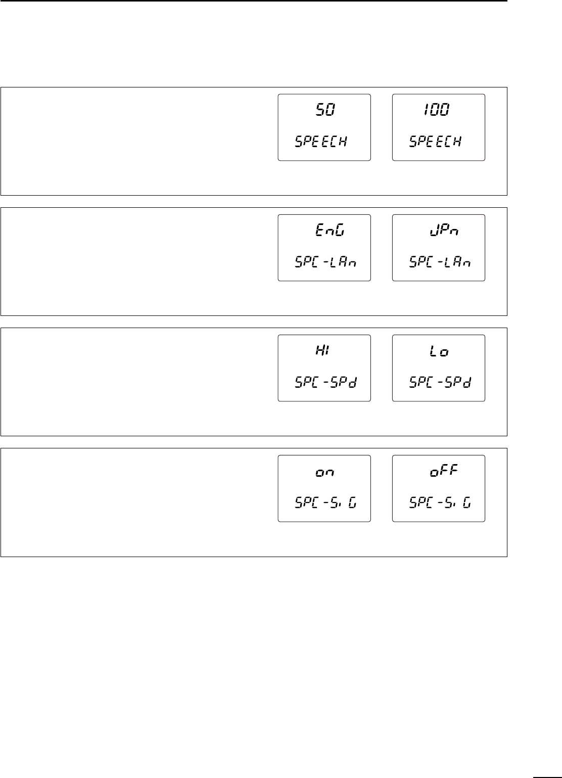
69
10
SET MODE
■Speech set mode
Output level
Adjust the speech audio output level within 0 (no out-
put) to 100 (maximum output) range.
•Default value: 50
Announcement language
Select the announcement language from English,
Japanese and OFF.
•EnG : Announces in English.
•JPn : Announces in Japanese
•oFF : No announcement.
Announcement speed
Select the announcement speed from high and low.
•HI : Faster announcement.
•Lo : Slower announcement.
S-meter level announcement
Turn the S-meter level announcement capability ON
and OFF.
•on : Announces S-meter level with the operating
frequency and mode.
•oFF : Announces the operating frequency and
mode only.
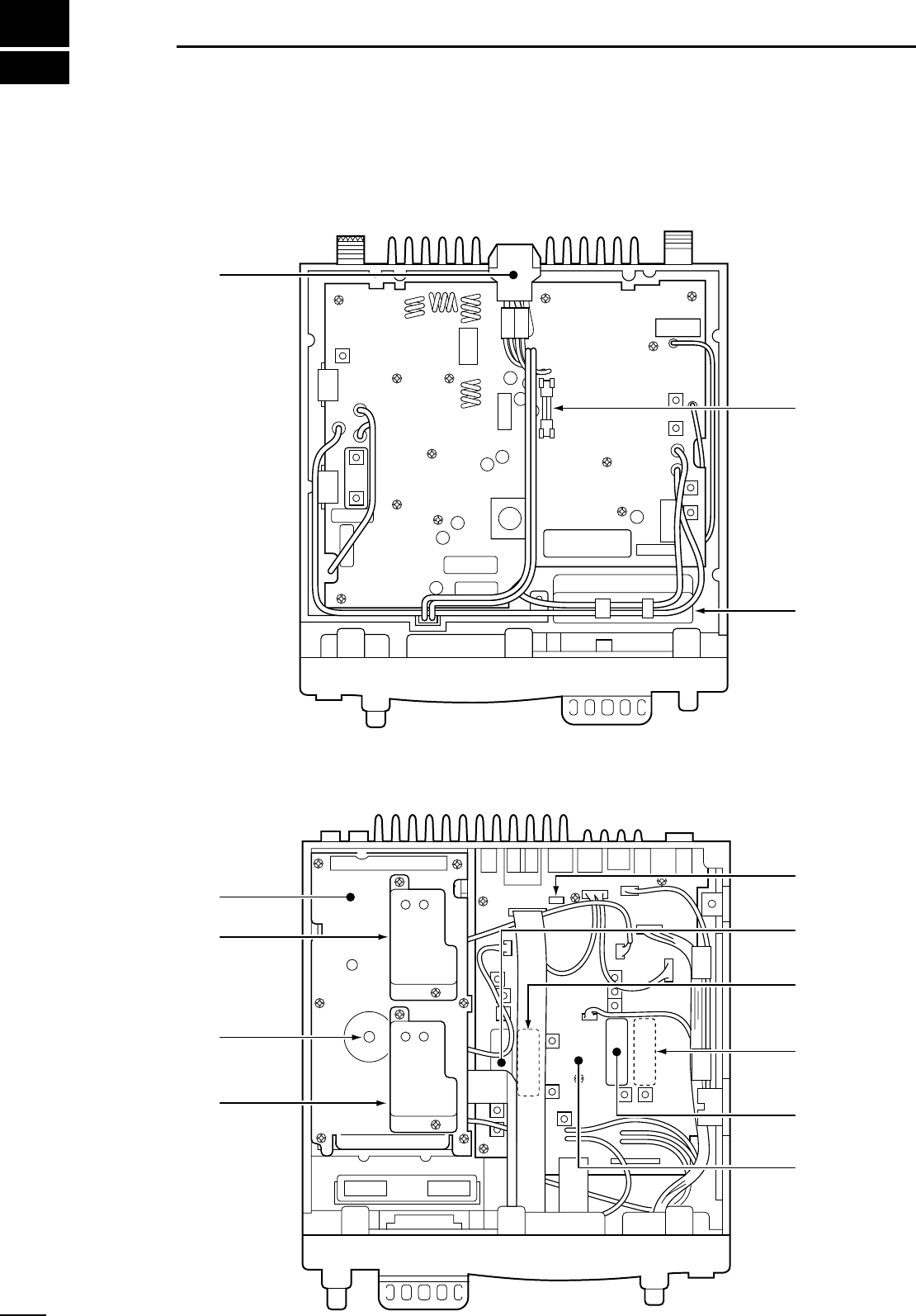
11
70
OPTION INSTALLATIONS
Circuitly fuse
(FGB 4 A)
Cooling fan
J1801
for UT-102
connection
SSB filter
(MAIN band)
CW-N filter
(MAIN band)
CW-N filter
(SUB band)
SSB filter
(SUB band)
MAIN unit
PLL unit
DSP unit
PLL ref. signal
(for UX-910)
DSP unit
DC power
connector
■Internal view
•Top view — PA unit
•Bottom view — PLL/MAIN unit
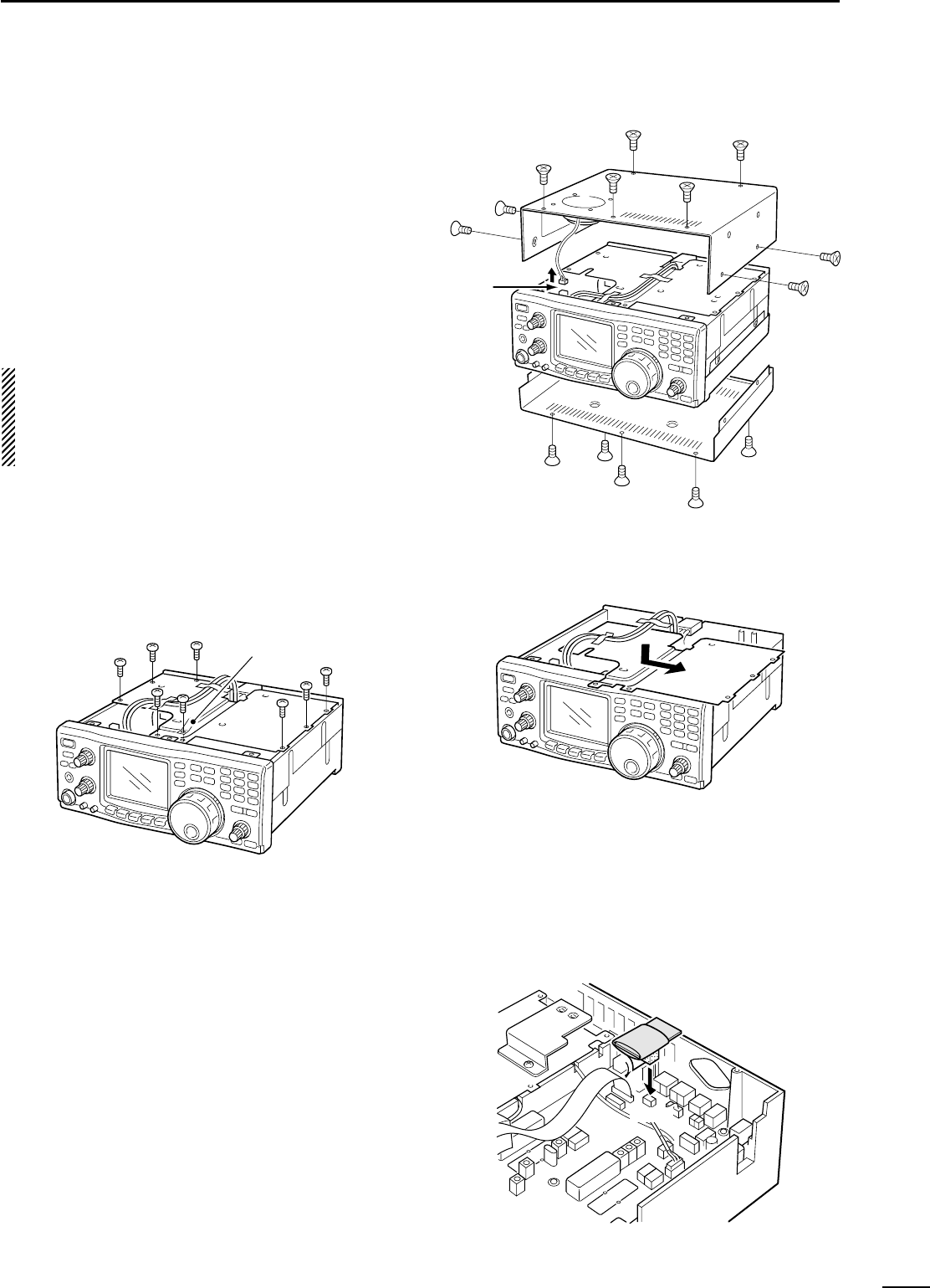
Follow the case and cover opening procedures
shown here when you want to install an optional
unit or adjust the internal units, etc.
qRemove the 5 screws from the top of the
transceiver and the 4 screws from the sides,
then lift up the top cover.
wTurn the transceiver upside down.
eRemove the 5 screws from the bottom of the
transceiver, then lift up the bottom cover.
CAUTION: DISCONNECT the DC power
cable from the transceiver before performing
any work on the transceiver. Otherwise, there
is a danger of electric shock and/or equipment
damage.
Disconnect the
speaker cable.
71
11
OPTION INSTALLATIONS
■Opening the transceiver’s case
The UT-102 announces the accessed readout’s fre-
quency, mode, etc. (S-meter level can also be an-
nounced—p. 69) in a clear, electronically-generated
voice, in English (or Japanese).
➥Push [SPCH] to announce the frequency, etc.
qRemove the bottom cover as shown above.
•Remove the UX-910 if you have installed it. (p. 73)
wRemove the protective paper attached to the bottom
of the UT-102 to expose the adhesive strip.
ePlug UT-102 into J1801 on the MAIN unit as shown
in the diagram at right.
rReturn the bottom cover to its original position.
tSet the speech level, announcement language and
S-meter announcement in the speech set mode
(p. 69) if desired.
UT-102
MAIN unit
J1801
■UT-102 VOICE SYNTHESIZER UNIT
◊Opening the PA unit cover
qRemove the 8 screws and grounding plate from the
PA unit cover.
wRemove fastening tape from the inside power cable.
eSlide the PA unit cover as shown below.
grounding plate
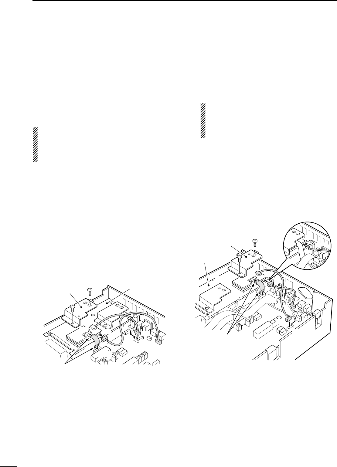
72
11 OPTION INSTALLATIONS
The UT-106 provides AF DSP functions such as noise
reduction and auto notch.
Up to 2 DSP units can be installed for simultaneous
DSP operation for both MAIN and SUB bands.
When only 1 DSP unit is installed, DSP functions can
be operated in either the MAIN or SUB band,
whichever is being accessed.
RECOMMENDATION:
When installing only 1 DSP unit, you can install into
either front or rear panel side. However, installing a
DSP unit into the front panel side may be easier and
also safer.
◊
Installing 1st DSP unit (front panel side)
qRemove the top and bottom covers.
•Remove the UX-910 if you have installed it. (p. 73)
wRemove the shielding plate.
eRemove the connection cable from J1751 on the
MAIN unit. Connect the cable into J1 on the UT-106.
rPlug the connection cable (P1) from the UT-106 to
J1751 on the MAIN unit.
tPlug the flat cable into J3 on the UT-106 and to
J1771 on the MAIN unit.
•Take care of the conductor direction.
•Attach the Velcro tape to the UT-106 and PLL unit shield-
ing plate.
yReturn the shielding plate, top cover and bottom
cover to their original positions.
◊
Installing 2nd DSP unit (rear panel side)
qRemove the top and bottom covers.
•Remove the UX-910 if you have installed it. (p. 73)
wRemove the shielding plate.
eRemove the connection cable from J1761 on the
MAIN unit. Connect the cable into J1 on the UT-106.
The cable between J1221 on the MAIN and J1
on the DSP unit, must be set in the groove of the
chassis (see diagram below).
Otherwise, the cable may be damaged when re-
turning the shield plate to its original position.
rPlug the connection cable (P1) from the UT-106 to
J1761 on the MAIN unit.
tPlug the flat cable into J3 on the UT-106 and to
J1781 on the MAIN unit.
•Take care of the conductor direction.
•Attach the Velcro tape to the UT-106 and PLL unit shield-
ing plate.
yReturn the shielding plate, top cover and bottom
cover to their original positions.
J1781
J1761
J3 J1
Shielding plate
UT-106
MAIN unit
PLL unit
Take care of the
conductor direction.
P1
J1
Set cable into the groove.
Take care of the
conductor direction.
J1771
J3 J1
J1751
Shielding plate
UT-106
MAIN unit
P1
PLL unit
■UT-106 DSP UNIT
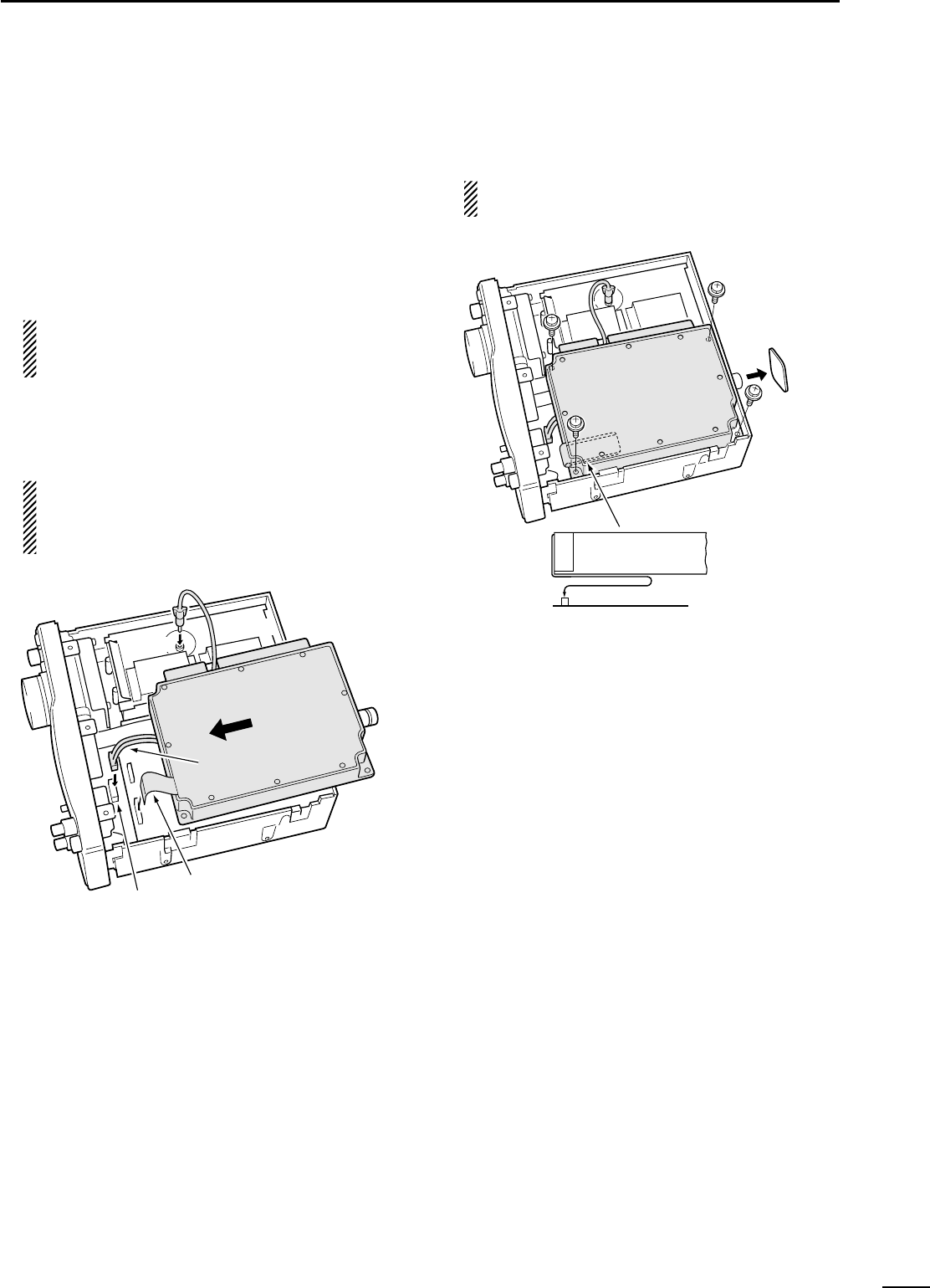
73
11
OPTION INSTALLATIONS
The UX-910 is a band unit for 1200 MHz band opera-
tion. FM, SSB (USB/LSB), CW and CW narrow mode
operations are available.
qRemove the bottom cover as shown in the diagram
on p. 71.
wRemove the antenna plate from the chassis using a
standard screw driver.
WARNING!
NEVER attempt to remove the antenna plate
using your finger, this may result in injury.
eConnect the FFC (Flexible Flat Cable) of the
UX-910 to J2 on the MAIN unit, DC power cable to
the power connector (W305) from the PA unit and
the coaxial cable to the J541 on the PLL unit.
CAUTION
NEVER catch the cables from the optional DSP
unit(s) between chassis and the UX-910, this
may damage the DSP unit(s) and/or transceiver.
rPlace the UX-910 using the supplied 4 screws.
BE CAREFUL not to drop the supplied screws
inside the transceiver.
tReturn the bottom cover to its original position.
Antenna plate
UX-910
Turn the flexible flat cable up under the UX-910.
J2
MAIN unit
Flexible flat cable
UX-910
J541
J2
UX-910
PLL unit
Power connector
DC power cable
Coaxial cable
Flexible flat cable
■UX-910 1200 MHz BAND UNIT
74
11 OPTION INSTALLATIONS
By installing the CR-293, the total frequency stability
of the transceiver will be improved.
qRemove the bottom cover as shown in the diagram
on p. 71.
•Remove the UX-910 if you have installed it. (p. 73)
wRemove the 6 screws from the PLL shield cover,
then lift up the PLL shield cover.
eDisconnect the FFC (Flexible Flat Cable) from the
DISPLAY unit and the connection cable connectors
from J501 and J1051 on the MAIN unit.
rRemove the 5 screws from the PLL unit, then lift up
the PLL unit.
tUnsolder the original reference crystal, then remove
it.
•The original reference crystal unit is soldered at both top
and bottom sides of the PCB (Printed Circuit Board).
yInstall the CR-293 and solder the leads.
uReturn the PLL unit, PLL shield cover and bottom
cover to their original positions.
CR-293 soldering
points
Original crystal soldering point
J501
Original crystal
CR-293
J1051
Flexible flat cable
Unsolder the
original
crystal.
PLL shield
cover
■CR-293 HIGH STABILITY CRYSTAL UNIT
75
11
OPTION INSTALLATIONS
The IC-910H has a CW narrow mode to provide better
S/N (Signal-to-Noise), or to reject interference. To op-
erate the CW narrow mode, an optional CW narrow fil-
ter is necessary.
NOTE: For CW narrow mode during satellite opera-
tion, the FL-133 (for SUB band filter) is necessary
since the SUB band circuit is used for receiving, al-
though the MAIN band display shows receive fre-
quency.
qRemove the bottom cover as shown in the diagram
on p. 71.
•Remove the UX-910 if you have installed it. (p. 73)
wDisconnect the connection cable connectors from
J501 and J1051 on the MAIN unit.
eRemove the 2 clips.
WARNING!
BE CAREFUL not to pinch your finger with the
clip.
rRemove the 6 screws from the MAIN unit, then lift
up the MAIN unit.
tInstall FL-132 or FL-133 to the specified position on
the MAIN unit.
ySolder then cut the leads, keeping 2–3 mm (1⁄8″) of
the leads from the bottom of the MAIN unit.
uReturn the MAIN unit and clips to their original po-
sitions.
iRe-connect the connection cable connector to J501
and J1051 on the MAIN unit.
oReturn the bottom cover to the original position.
(MAIN)
(SUB)
FL-132
(MAIN)
FL-133
(SUB)
PLL unit
MAIN unit
J1051
J501
Clips
■FL-132/FL-133 CW NARROW FILTER
FILTER Passband width
at –6dB at –60 dB
Built-in filter 2.3 kHz 4.2 kHz
FL-132/133 500 Hz 1.34 kHz

POWER
RECEIVE
TRANSMIT
SCAN
DISPLAY
PROBLEM POSSIBLE CAUSE SOLUTION REF.
SPEECH
11
76
MAINTENANCE
■Troubleshooting
The following chart is designed to help you correct
problems which are not equipment malfunctions. If you are unable to locate the cause of a problem or
solve it through the use of this chart, contact your near-
est Icom Dealer or Service Center.
Power does not come on
when [POWER] is pushed.
No sounds comes from
the speaker.
Sensitivity is low.
Received audio is dis-
torted.
Transmitting is impossible.
Output power is too low.
No contact possible with
another station.
Transmitted signals are
distorted.
Repeater cannot be ac-
cessed.
Programmed scan does
not start.
Memory scan does not
start.
Mode select scan does not
start.
No announcement when
[SPCH] is pushed.
The displayed frequency
does not change properly.
•DC power cable is improperly connected.
•Fuse is blown.
•Volume level is too low.
•The squelch is closed.
•The transceiver is in the transmitting condition.
•The antenna is not connected properly.
•The attenuator is activated.
•The S-meter squelch is activated.
•Incorrect sideband (USB/LSB) is selected.
•Receiving an FM signal.
•Noise blanker is activated.
•Noise reduction is activated.
•PTT lock function is activated.
•[RF PWR] is set too far counterclockwise.
•[MIC GAIN] is set too far counterclockwise.
•Split frequency operation or duplex operation is
activated.
•RIT function is activated.
•[MIC GAIN] to far clockwise.
•Duplex operation is not activated.
•No subaudible tone or incorrect tone frequency
is selected.
•VFO mode is not selected.
•[RF/SQL] is assigned to RF gain and squelch is
opened.
•Memory mode is not selected.
•No memory channels are programmed.
•Mode select scan mode has not been selected.
•Only one channel is programmed with the se-
lected operating mode.
•The voice synthesizer unit has not been in-
stalled.
•The announcement level is set to “0”or too low.
•The announcement language is set to “oFF.”
•The dial lock function is activated.
•The internal CPU has malfunctioned.
•Reconnect the DC power cable correctly.
•Check the cause, then replace the fuse with a
spare one. (Fuses are installed in the DC power
cable and the internal PA unit.)
•Rotate [AF] clockwise to obtain a suitable listen-
ing level.
•Rotate [RF/SQL] to 12 o’clock position to open
the squelch.
•Push [TRANSMIT] to receive or check the SEND
line of an external unit, if desired.
•Reconnect to the antenna connector.
•Push [ATT] to turn the attenuator OFF.
•Rotate [RF/SQL] to the position where the noise
just disappears.
•Switch USB and LSB by pushing [SSB/CW] for
1 sec.
•Push [FM] to select FM mode.
•Push [AFC/NB] to turn the noise blanker function
OFF.
•Set the noise reduction level in the NR set mode
for maximum readability using [SET] and
[AFC/NB•NR], or turn OFF the function by push-
ing [AFC/NB•NR] for 1 sec.
•Turn the PTT lock function OFF in the TRANSMIT
set mode using [SET] and [TRANSMIT].
•Rotate [RF PWR] clockwise.
•Rotate [MIC GAIN] clockwise.
•Push [SPLIT] momentarily or for 1 sec. to turn the
split or duplex function OFF.
•Push [RIT] to turn the RIT function OFF.
•Set [MIC GAIN] to a suitable level.
•Push [SPLIT•DUP] for 1 sec. to turn duplex oper-
ation ON.
•Push [TONE] to activate the subaudible tone or
select a suitable tone frequency in the FM set
mode using [SET] and [FM].
•Push [V/M 1] to select VFO mode.
•Reset [RF/SQL] control assignment and set it to
the threshold point.
•Push [V/M 1] to select memory mode.
•Program desired frequencies into memory chan-
nels.
•Push [SPCH•LOCK] for 1 sec. on the desired op-
erating mode programmed channel.
•Program more than two channels with the desired
operating mode.
•Install the optional vice synthesizer unit, UT-102.
•Set the announcement level to a suitable level in
the SPCH set mode using [SET] and [SPCH].
•Set the announcement language to “Eng”(or JPn)
in the SPCH set mode using [SET] and [SPCH].
•Push [SPCH•LOCK] to turn the lock function OFF.
•Reset the CPU.
–
p. 77
p. 26
p. 26
pgs.
2, 13
–
p. 29
p. 26
p. 23
p. 23
p. 30
p. 31
p. 66
p. 32
p. 32
p. 37
p. 27
p. 32
p. 34
p. 35
p. 21
p. 26
p. 40
p. 41
p. 47
p. 41
p. 71
p. 69
p. 69
p. 25
p. 77
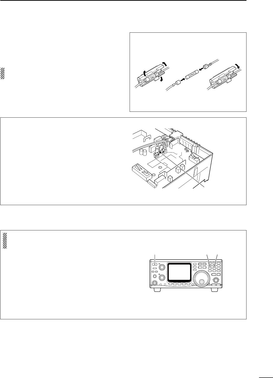
77
11
MAINTENANCE
■Fuse replacement
If a fuse blows or the transceiver stops functioning, try
to find the source of the problem, and replace the dam-
aged fuse with a new, rated fuse.
CAUTION: DISCONNECT the DC power cable
from the transceiver when changing a fuse.
The IC-910H has 2 types of fuses installed for trans-
ceiver protection.
•DC power cable fuses ................................FGB 30 A
•Circuitry fuse ................................................FGB 4 A
DC POWER CABLE FUSE REPLACEMENT
30 A fuse
CIRCUITRY FUSE REPLACEMENT
The 13.8 V DC from the DC power cable is applied to
all units in the IC-910H, except for the power ampli-
fier, through the circuitry fuse. This fuse is installed in
the PA unit.
qRemove the top cover as shown on p. 71.
wRemove the 11 screws from the PA shielding plate,
then remove the plate.
eReplace the circuitry fuse as shown in the diagram
at right.
rReplace the PA shielding plate and top cover.
Circuitry fuse (4 A)
■CPU resetting
Resetting CLEARS all programmed contents in
memory channels and returns programmed values
in set mode to default values.
When first applying power or when the function
seems to be displaying erroneous information, reset
the CPU as follows:
qMake sure the transceiver power is OFF.
wWhile pushing [MW 4] and [M-CL 5], push
[POWER] to turn power ON.
•The internal CPU is reset.
•The transceiver displays its initial VFO frequencies
when resetting is complete.
[POWER] [MW 4] [M-CL 5]
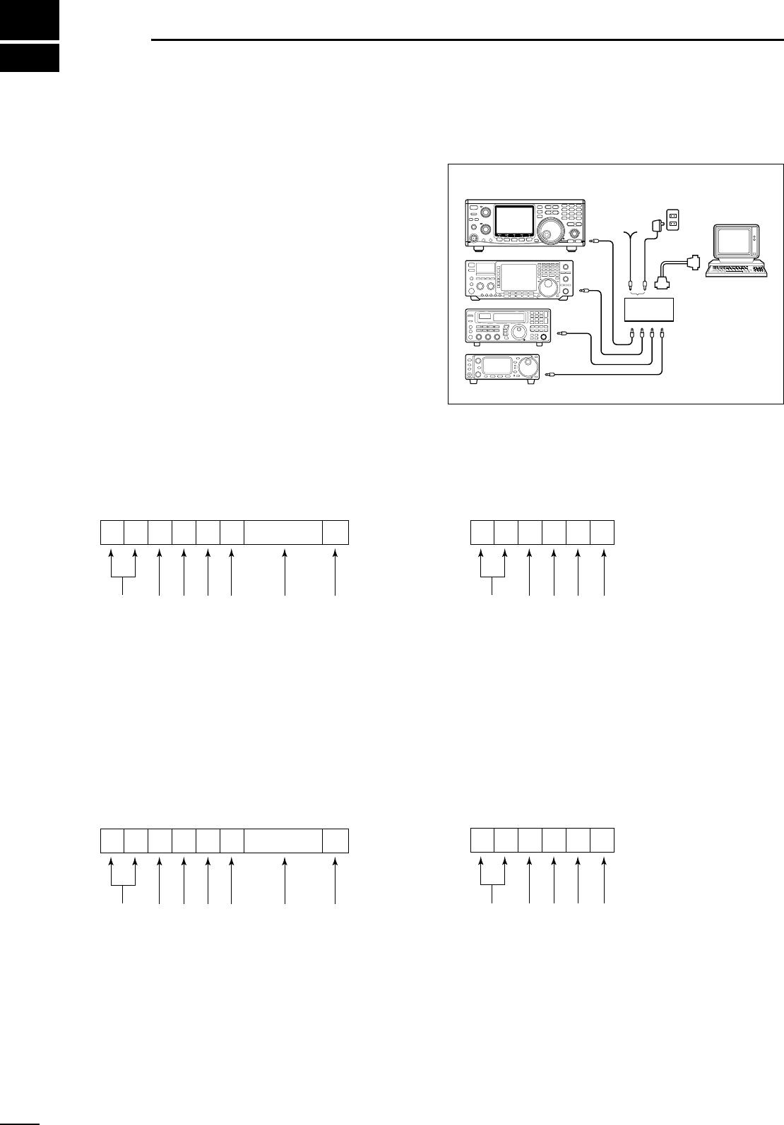
CONTROLLER TO IC-910H
FE
FE
FE 60 E0 Cn Sc Data area FD
Preamble code (fixed)
Transceiver’s default address
Controller’s default address
Command number
(see table at right)
Sub command number
(see table at right)
BCD code data for frequency or
memory number entry
End of message code (fixed)
OK MESSAGE TO CONTROLLER
FE FE E0 60 FB FD
Preamble code (fixed)
Controller’s default address
Transceiver’s default address
OK code (fixed)
End of message code (fixed)
NG MESSAGE TO CONTROLLER
FE FE E0 60 FA FD
Preamble code (fixed)
Controller’s default address
Transceiver’s default address
NG code (fixed)
End of message code (fixed)
IC-910H TO CONTROLLER
FE E0 60 Cn Sc Data area FD
Preamble code (fixed)
Controller’s default address
Transceiver’s default address
Command number
(see table at right)
Sub command number
(see table at right)
BCD code data for frequency or
memory number entry
End of message code (fixed)
qwert y u
qwert y u
13
78
CONTROL COMMAND
•CI-V connection example
The transceiver can be connected through an optional
CT-17 CI-V LEVEL CONVERTER to a personal computer
equipped with an RS-232C port. The Icom Communi-
cations Interface-V (CI-V) controls the following func-
tions of the transceiver.
Up to 4 Icom CI-V transceivers or receivers can be
connected to a personal computer equipped with an
RS-232C port. See p. 59 for setting the CI-V condition
using set mode.
•Data format
The CI-V system can be operated using the following
data formats. Data formats differ according to com-
mand numbers. A data area or sub command is added
for some commands.
■Remote jack (CI-V) information
9–15
V DC
personal
computer
ct- 17
BC-25
(optional)
IC-910H
mini-plug cable

79
13
CONTROL COMMAND
Command
Sub command
00 —
01 ××
02 —
03 —
04 —
05 —
00
06 01
03
04
—
00
01
07 A0
B0
D0
D1
—
01–0106*
08
09 —
0A —
0B —
0C —
0D —
00
0E 01
D0
D3
00
01
0F 10
11
12
00
01
02
03
04
10 05
06
07
08
09
10
11
11 00
20
Description
Send frequency data for trans-
ceive.
Send mode data for transceive.
Read band edge frequencies.
Read operating frequency data.
Read operating mode data.
Set operating frequency.
Set LSB.
Set USB.
Set CW.
Set FM.
Select VFO mode.
Select VFO A.
Select VFO B.
Equalize VFO A and VFO B.
Switch VFO A and VFO B.
Select MAIN VFO.
Select SUB VFO.
Select memory mode.
Select memory channel.
*1A=0100 1b=0101
2A=0102 2b=0103
3A=0104 3b=0105
Call=0106
Memory write.
Transfer memory contents to
VFO.
Memory clear.
Read duplex offset frequency.
Set duplex offset frequency.
Cancel scan.
Start scan.
Set scan resume OFF.
Set scan resume ON.
Turn the split function OFF.
Turn the split function ON.
Set simplex operation.
Set DUP– operation.
Set DUP+ operation.
Set 1 Hz tuning step.
Set 10 Hz tuning step.
Set 50 Hz tuning step.
Set 100 Hz tuning step.
Set 1 kHz tuning step.
Set 5 kHz tuning step.
Set 6.25 kHz tuning step.
Set 10 kHz tuning step.
Set 12.5 kHz tuning step.
Set 20 kHz tuning step.
Set 25 kHz tuning step.
Set 100 kHz tuning step.
Turn attenuator OFF.
Turn attenuator ON.
Command
Sub command
00
13
01
02
01
02
03
04
06
14 09
0A
0B
0C
0E
0F
01
15
02
02
12
22
40
+level data
41
16 42
43
44
46
47
4A
19 00
00
01
02
+level data
03
+level data
04
1A +level data
05
+level data
06
07
08
Description
Announce all S-meter levels,
displayed frequency and mode.
Announce displayed frequency.
Announce operating mode.
[AF] level setting (0=max. CCW;
128=center; 255=max. CW).
[RF GAIN] level setting
(0=max. CCW; 255=max. CW).
[SQL] level setting (0=max.
CCW; 255=max. CW).
[IF SHIFT] level setting (0=max.
CCW; 128=center; 255=max. CW).
Set noise reduction level
(0=0%; 255=100%).
Set CW pitch (0=300 Hz;
255=900 Hz).
[RF PWR] level setting (0=max.
CCW; 128=center; 255=max. CW).
[MIC GAIN] level setting (0=max.
CCW; 128=center; 255=max. CW).
Key speed setting (0=6 wpm;
255=60 wpm).
Set mic. compressor level
(0=0%; 255=100%).
Set break-in delay (0=2.0 sec;
255=13.0 sec.).
Read squelch condition (open
or closed).
Read S-meter level.
Set pre-amp (0=OFF; 1=ON).
Set AGC (0=Slow; 1=Fast).
Set noise blanker (0=OFF; 1=ON).
Set noise reduction level
(0=OFF; 1–15=ON).
Set auto notch filter
(0=OFF; 1=ON).
Set subaudible tone
(0=OFF; 1=ON).
Set tone squelch (0=OFF; 1=ON).
Set mic. compressor
(0=OFF; 1=ON).
Set VOX (0=OFF; 1=ON).
Set break-in (0=OFF; 1=ON).
Set AFC (0=OFF; 1=ON).
Read the transceiver ID.
Read/write memory channel.
Set satellite memory.
Set VOX gain level
(0=0%; 255=100%).
Set VOX delay
(0=0 sec.; 20=2.0 sec.).
Set anti-VOX
(0=0%; 255=100%).
Attenuation level setting
(0=0%; 255=100%).
Set RIT (0=OFF; 1=ON; 2=Sub dial).
Set satellite mode
(0=OFF; 1=ON).
Set simple bandscope
(0=OFF; 1=ON).

•General
•Frequency coverage : (Unit: MHz)
*1Optional UX-910
*2Guaranteed range is 144.0–148.0 MHz.
*3Guaranteed range is 430.0–450.0 MHz.
*4Guaranteed range is 1240.0–1300.0 MHz.
•Mode : USB, LSB, CW, FM, FM-N*
*Not available in 1200 MHz
•No. of memory Ch. : 212 (99 regular, 6 scan edges, 1
calls for each band) plus 10
satellite memories)
•Antenna connector : SO-239 (50 Ω; VHF)
Type-N (50 Ω; UHF)
•Usable temp. range : –10˚C to +60˚C;
+14˚F to +140˚F
•Frequency stability : Less than ±3 ppm
(–10 to 60˚C; +14 to +140˚F)
•Frequency resolution : 1 Hz minimum
•Power supply : 13.8 V DC ±15%
(negative ground)
•Current drain (at 13.8 V DC; approx.):
Transmit Max. power 23.0 A
Receive Standby 2.0 A
(3.0 A; UX-910)
Max. audio 2.5 A
(3.5 A; UX-910)
•Dimensions : 241(W) ×94(H)×239(D) mm
(projections not included) 91⁄2(W)×311⁄16(H) ×913⁄32(D) in
•Weight (approx.) : 4.5 kg; 10 lb
(5.35 kg; 11 lb 13 oz w/UX-910)
•ACC 1 connector : 8-pin DIN connector
•CI-V connector : 2-conductor 3.5(d) mm (1⁄8″)
•DATA connectors : 6-pin mini DIN ×2
(for MAIN and SUB)
•Transmitter
•Output power (continuously adjustable):
144 MHz 5–100 W
430(440) MHz 5–75 W
1200 MHz 1–10 W (optional UX-910)
•Modulation system :
SSB Balanced modulation
FM
Variable reactance modulation
•Spurious emission :
144/430(440) MHz More than 60 dB
1200 MHz More than 50 dB
•Carrier suppression : More than 40 dB
•Unwanted sideband : More than 40 dB
suppression
•
Microphone connector
: 8-pin connector (600 Ω)
•KEY connector : 3-conductor 3.5(d) mm (1⁄4″)
•Receiver
•Receive system :
VHF SSB, CW
Single conversion superheterodyne
FM
Double conversion superheterodyne
UHF SSB, CW
Double conversion superheterodyne
FM Triple conversion superheterodyne
•Intermediate frequencies: (Unit: MHz)
•Sensitivity :
SSB, CW (10 dB S/N) Less than 0.11 µV
FM (12 dB SINAD) Less than 0.18 µV
•Squelch sensitivity (threshold):
SSB, CW Less than 1.0 µV
FM Less than 0.18 µV
•Selectivity :
SSB, CW More than 2.3 kHz/–6 dB
Less than 4.2 kHz/–60 dB*
FM More than 15.0 kHz/–6 dB
Less than 30.0 kHz/–60 dB*
FM-N More than 6.0 kHz/–6 dB
Less than 18.0 kHz/–36 dB
CW-N More than 0.5 kHz/–6 dB
(w/FL-132 or FL-133) Less than 1.34 kHz/–60 dB*
*Except 1200 MHz band
•Spurious and image rejection ratio:
144/430(440) MHz More than 60 dB
1200 MHz More than 50 dB
•AF output power : More than 2.0 W at 10%
(at 13.8 V DC) distortion with an 8 Ωload
•RIT variable range :
144/430(440) MHz ±1.0 kHz (SSB, CW)
±5.0 kHz (FM)
1200 MHz ±2.0 kHz (SSB, CW)
±10.0 kHz (FM)
•
IF SHIFT variable range
: More than ±1.2 kHz
•PHONES connector : 3-conductor 6.35(d) mm (1⁄4″)
•Ext. SP connectors : 2-conductor 3.5 (d) mm (1⁄8″)
/8Ω×2 (for MAIN and SUB)
14
80
SPECIFICATIONS
All stated specifications are typical and subject to
change without notice or obligation.
Version
144 MHz 430(440) MHz 1200 MHz*1
U.S.A.
Tx: 144.0–148.0 Tx: 430.0–450.0 Tx: 1240.0–1300.0
Rx: 136.0–174.0*
2
Rx: 420.0–480.0*
3
Rx: 1240.0–1320.0*
4
Europe 144.0–146.0 430.0–440.0
1240.0–1300.0
Australia
144.0–148.0 430.0–450.0
1240.0–1300.0
Sweden
144.0–146.0 432.0–438.0
1240.0–1300.0
MAIN BAND SUB BAND
1st 2nd 3rd 1st 2nd 3rd
SSB
10.8500
——
10.9500
——
CW
10.8491
——
10.9491
——
FM
10.8500
0.455 —
10.9500
0.455 —
SSB
71.2500 10.8500
—
71.3500 10.9500
—
CW
71.2491 10.8491
—
71.3491 10.9491
—
FM
71.2500 10.8500
0.455
71.3500 10.9500
0.455
SSB
243.8500
10.8500
—
243.9500
10.9500
—
CW
243.8491
10.8491
—
243.9491
10.9491
—
FM
243.8500
10.8500
0.455
243.9500
10.9500
0.455
144 MHz
430(440) MHz
1200 MHz
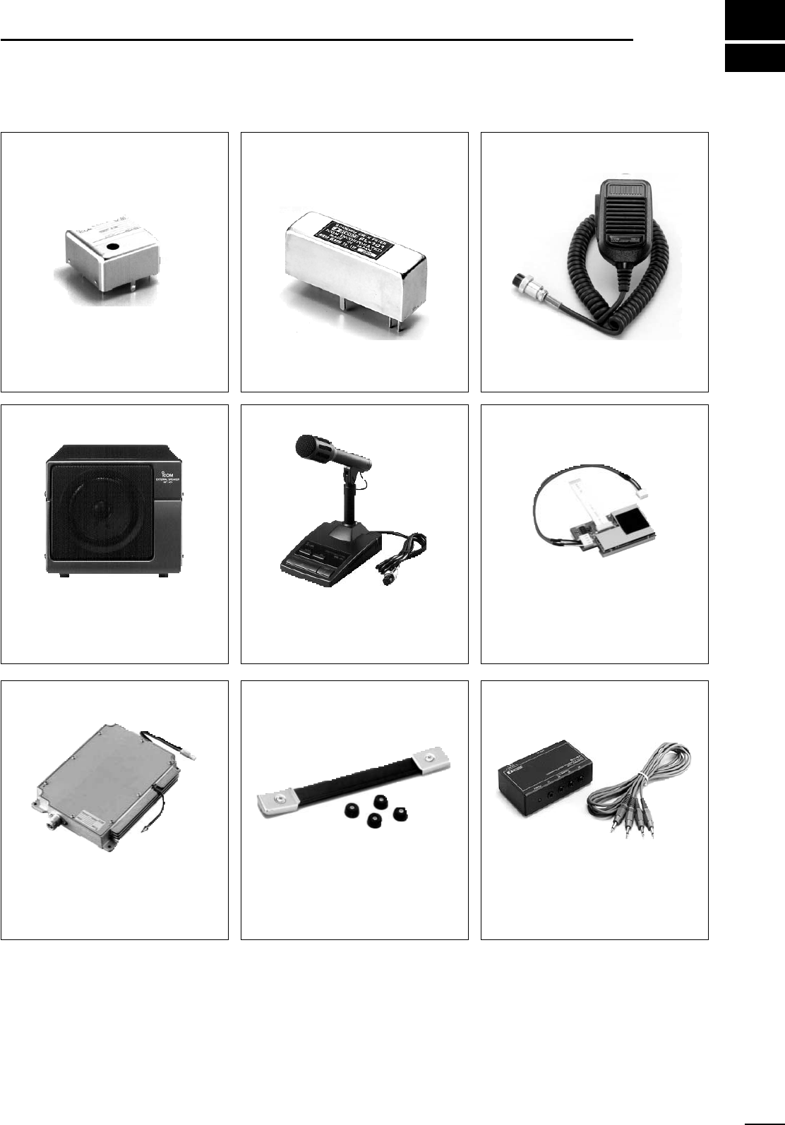
15
81
OPTIONS
SM-20 DESKTOP MICROPHONE
Unidirectional, electret microphone for
base station operation. Includes [UP]
and [DOWN] switches and a low cut
function.
SP-21 EXTERNAL SPEAKER
Designed for base station operation.
•Input impedance: 8 Ω
•Max. input power: 5 W
CT-17 CI-V LEVEL CONVERTER
For remote transceiver control using a
personal computer. You can change
frequencies, operating mode, memory
channels, etc.
HM-12 HAND MICROPHONE
Hand microphone equipped with
[UP]/[DOWN] switches. Same as that
supplied with the transceiver.
CR-293 HIGH STABILITY
CRYSTAL UNIT
Frequency stability: ±0.5 ppm
(0˚C to +60˚C)
FL-132 (for MAIN band)
FL-133 (for SUB band and satellite
operation)
CW NARROW FILTERS
Have good shape factor and provide
better CW reception during crowded
band conditions. 500 Hz/–6dB
MB-23 CARRYING HANDLE
Carrying handle, convenient for
portable operation.
UX-910 1200 MHz BAND UNIT
Allows you additional all mode opera-
tion on the 1200 MHz band.
UT-106 DSP UNIT
Allows AF DSP capabilities, including
noise reduction and auto notch filter.
AG-25 (for 144 MHz band),
AG-35 (for 430(440) MHz band),
AG-1200 (for 1200 MHz band)
WEATHER-PROOF PREAMPLIFIERS
External all-weather, mast mounting preamplifiers for com-
pensating for coaxial cable loss.
IC-MB5 MOBILE MOUNTING BRACKET
Transceiver mounting bracket for mobile operation.
SP-7 EXTERNAL SPEAKER
Compact speaker for base station operation.
UT-102 VOICE SYNTHESIZER UNIT
Announces the receive frequency, mode and S-meter level
in a clear, electronically-generated voice, in English (or
Japanese).

Count on us!
1-1-32 Kamiminami, Hirano-ku, Osaka 547-0003 Japan
A-5699H-1EX-w
Printed in Japan
© 2000 Icom Inc.