ICOM orporated IC-A5 Handheld Aircraft Transmitter with VOR Navigation User Manual Manual
ICOM Incorporated Handheld Aircraft Transmitter with VOR Navigation Manual
UserManual.wiki
>
ICOM orporated
>
IC A5 User Manual
Manual
Navigation menu
Upload a User Manual
Namespaces
Wiki Guide
HTML
PDF
Info
Views
User Manual
Discussion / Help
Navigation
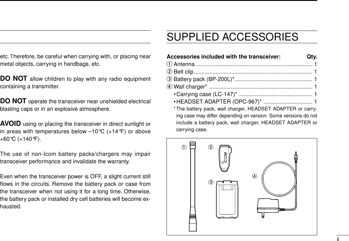
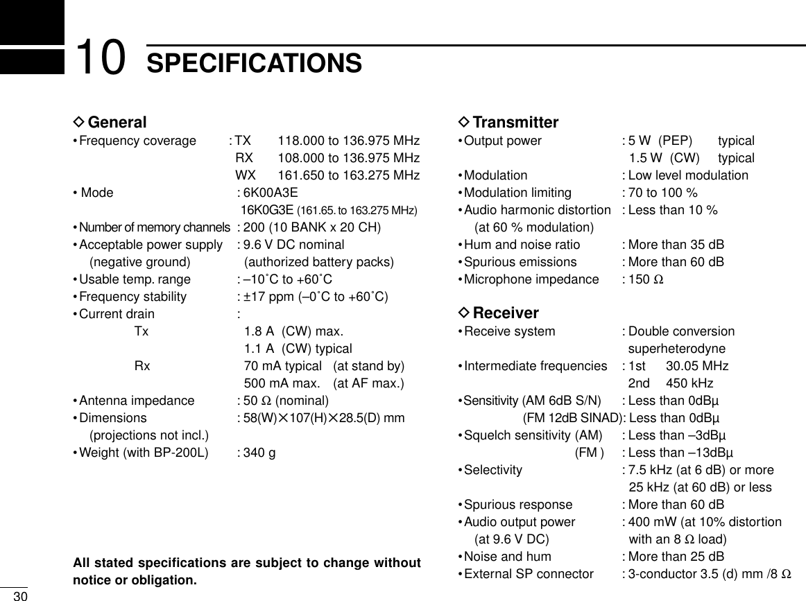
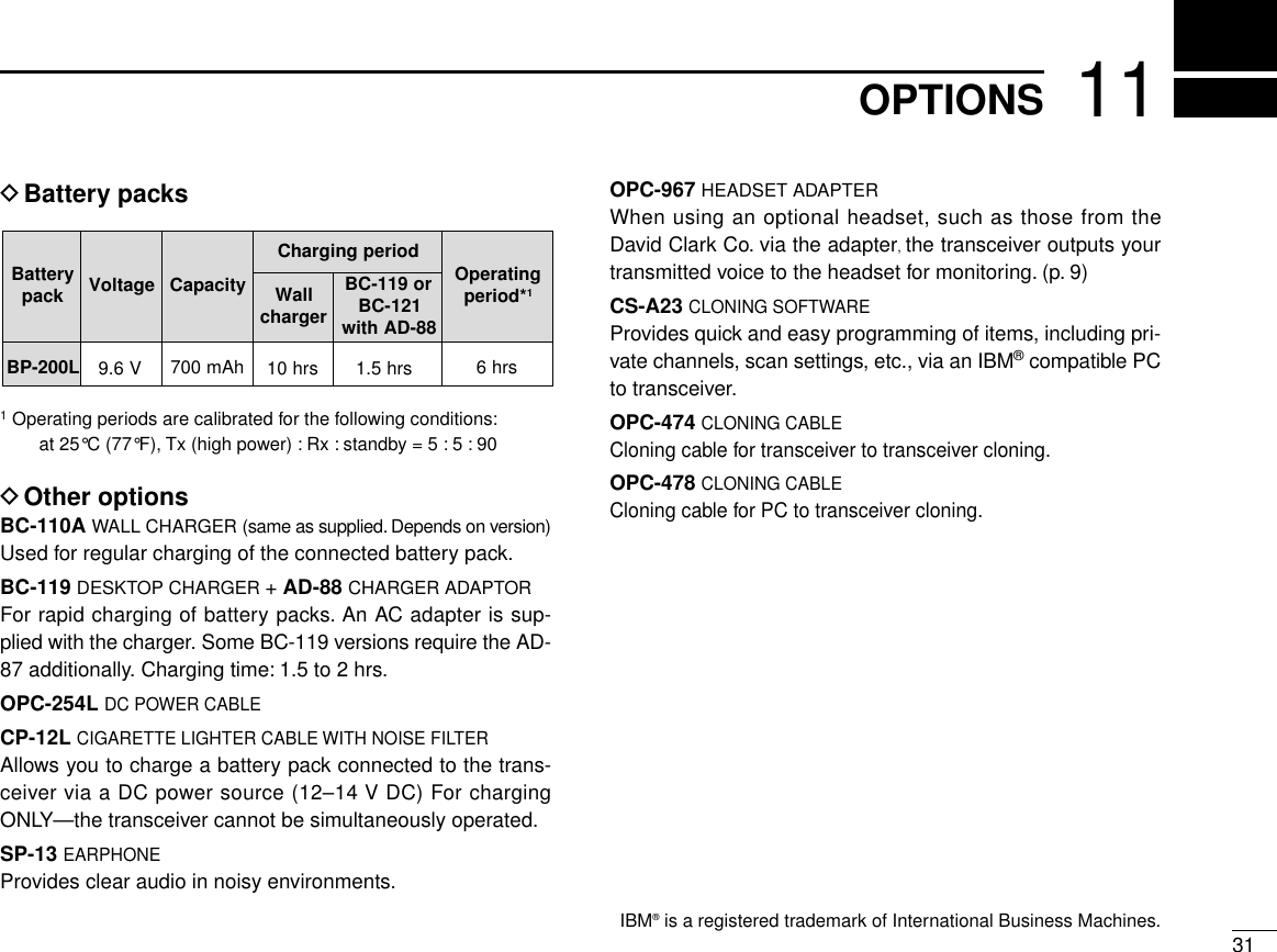
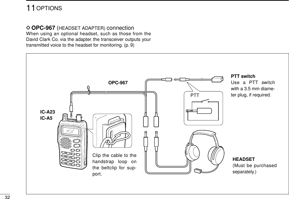
![FOREWORD .................................................................................... iEXPLICIT DEFINITIONS ................................................................. iCAUTIONS ....................................................................................... iSUPPLIED ACCESSORIES............................................................. iiTABLE OF CONTENTS .................................................................. iii1 ACCESSORY ATTACHMENT .................................................. 12 PANEL DESCRIPTION ........................................................ 2–7■Panel description ............................................................... 2–5■Function display ................................................................ 6–73 BASIC OPERATION ............................................................ 8 –7■DIAL↔[Y]/[Z] trade function ...................................................8■Setting a frequency ................................................................ 8■Lock function .......................................................................... 8■Accessing 121.5 MHz emergency frequency ......................... 8■Setting a squelch level ........................................................... 9■Side tone function .................................................................. 9■Display backlighting ............................................................... 9■Low battery indicator .............................................................. 9■Receiving ............................................................................. 10■Transmitting .......................................................................... 10■Selecting a weather channel................................................. 11■Side tone function .................................................................. 6■Lock function .......................................................................... 6■Display backlighting ............................................................... 6■Low battery indicator .............................................................. 6■Dial select function ................................................................. 74 MEMORY OPERATION .......................................................... 12■Memory channel selection ................................................... 12■Transferring memory contents ............................................. 12■Programming a memory channel ......................................... 13■Memory names .................................................................... 145 SCAN OPERATION ................................................................ 16■Scan types ........................................................................... 16■COM band scan ................................................................... 16■Memory scan ....................................................................... 16■Weather channel scan ......................................................... 17■“TAG” channels ................................................................... 176 VOR NAVIGATION (IC-A23 only) .................................... 18– 24■VOR indications ................................................................... 18■VOR functions ...................................................................... 19■Flying to a VOR station ........................................................ 20■Entering a desired course .................................................... 22■Crosschecking position ........................................................ 22■Duplex operation ................................................................. 247 BATTERY PACKS ........................................................... 25– 27■Charging precautions ........................................................... 25■Battery pack charging .......................................................... 25■About the battery pack ......................................................... 27■IBattery pack CAUTION ....................................................... 278 CLONING ................................................................................ 289 TROUBLESHOOTING ............................................................ 2910 SPECIFICATIONS .................................................................. 3011 OPTIONS ................................................................................ 31■OPC-967 connection ............................................................ 32iiiTABLE OF CONTENTS](https://usermanual.wiki/ICOM-orporated/IC-A5/User-Guide-107377-Page-4.png)
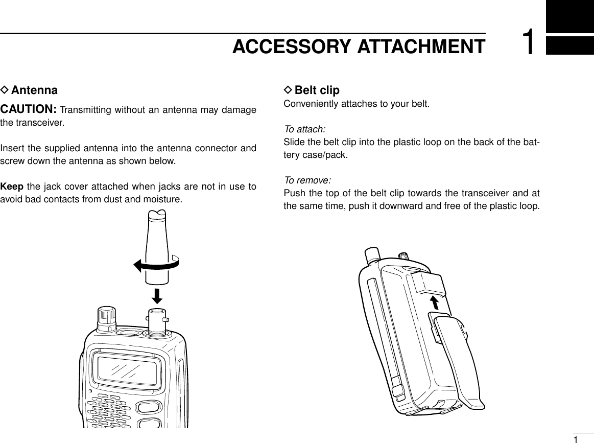
![22PANEL DESCRIPTION■Panel descriptione[DIAL]r[MIC/SP]w[PTT]t[ANT]!0[CLR(DIAL/ÙÚ)]!1[ANL(REC)]!2[BANK(PLAY)]!3[FUNCTION]!4[MR(MW)]!5[ENT(WX)]q[LIGHT]yDisplayu[UP/DOWN]i[SQL(SCAN)]Tx/Rxindicator!6[DIGIT KEYS]o[PWR]ui!0!1!2!3!4!5o!6](https://usermanual.wiki/ICOM-orporated/IC-A5/User-Guide-107377-Page-6.png)
![32PANEL DESCRIPTIONqLIGHT [LIGHT] (p. 10)Turns the light for display and keypad ON or OFF.wPTT SWITCH [PTT] (p. 11)Push and hold to transmit; release to receive.eTUNING DIAL [DIAL] (P. 8)➥Rotate [DIAL] to select the desired frequency. (default)➥Rotate [DIAL] to select the BANK number. (default)➥Rotate [DIAL] to select the memory channel or WXchannel number. (default)➥Rotate [DIAL] to adjust the audio level.rEXTERNAL SPEAKER AND MICROPHONE JACKSMIC/SP] (pgs. 29, 30)Connect an optional speaker-microphone or headset, if de-sired.The internal microphone will not function when eitheris connected.tANTENNA CONNECTOR [ANT]Connects the supplied antenna.yFUNCTION DISPLAY (pgs. 6, 7)uUP/DOWN KEYS [Y]/[Z] (P. 8)➥Push [Y] to increase the audio level, push [Z] todecrease the audio level. (default)➥Push to select the operating channel or fre-quency.➥Push to select the BANK number.iSQUELCH KEY [SQL] (P. 9)➥Push [SQL], then rotate the [DIAL] (or push[Y]/[Z]) to select the squelch level.• 24 squelch levels and squelch open (0) are available.➥Push , then push [SQL] to starts scan func-tion:Frequency mode: Frequency full scan function.MEMORY mode: Memory channel scan function.oPOWER SWITCH [PWR]➥Push and hold for 0.5 sec. to turn the power ONor OFF.➥While pushing [Y]/[Z], push [PWR] to enter thecloning function mode.!0 CLR KEY [CLR]➥Push , then push [CLR] to exchange the etuning Dial function and uUP [Y]/DOWN [Z]switch function;- Dial: tuning (default)- UP[Y]/DOWN[Z]: audio level setting (default)NOTE: You can adjust the audio level via [DIAL]and select the frequency, memory channel orBANK number via UP[Y]/DOWN[Z] keys.➥Push [CLR] to turn to the frequency mode, whenmemory channel, WX channel or 121.5 MHz isselected.](https://usermanual.wiki/ICOM-orporated/IC-A5/User-Guide-107377-Page-7.png)
![42PANEL DESCRIPTION!0 CLR KEY [CLR] (continue)➥Push [CLR] to cancel the SCAN function.➥Push [CLR] to cancel the direct frequency enter-ing with digit key.➥Push [CLR] to turn the squelch level adjustingmode OFF.!1 ANL KEY [ANL]➥Push to turn the ANL function ON or OFF.➥Push , then push [ANL (REC)] to turn therecording function ON.- The transceiver records the receiving signal or opera-tors voice for 20 sec.!2 BANK KEY [BANK] (P. 12)➥Push [BANK] to enter the BANK selection modewhile memory channel is selected, push [CLR]to exit the BANK selection mode.➥Push , then push [BANK] to play therecorded signals.!3 FUNCTION KEY [F]Push to call up the function indicator, “”, thenpush another key to access its secondary function.•“ ” appears for 3 sec. after [F] is pushed; at this timepushing [F] again cancels the indication. (P. 6)•This key cannot activate during transmit.NOTE: In general, “”disappears when another key ispushed to activate a secondary function. However, some keyswhich have more than one secondary function, (such as[DUP]), do not cancel “”. In this case, “”disappears auto-matically after 3 sec.!4 MEMORY MODE KEY [MR (MW)] (P. 12)➥Push [MR] to call the memory channel mode,push [CLR] to exit the memory channel mode.➥Push , then push [MR (MW)] to program thecontents into the memory channels.➥Push [MR] to program the memory commentwhen the memory comment function is enabled.!5 ENTER KEY [ENT(WX)] (P. 8)➥Push [ENT] to enter the numeral input. Entersconsecutive zero digits.➥Push , then push [ENT] to enter the weatherchannel selection mode. (U.S.A. version only)•Rx/Tx indicator➥Lights red during the transmit mode.➥Lights green during receiving a signal or squelch isopen.NOTE: Some functions may not be available depending onversion. Please consult your dealer.](https://usermanual.wiki/ICOM-orporated/IC-A5/User-Guide-107377-Page-8.png)
![52PANEL DESCRIPTION!6 DIGIT KEYS ➥Input the specified digit during frequency input, memorychannel selection, etc.➥In addition, each key has one or more secondary func-tions after pushing [F] as follows:➥Push , then push [0] to select the 121.5MHz emergency frequency. (P. 8)➥Push [CLR] to cancel the direct frequency enter-ing with digit key.➥Push , then push [1] to select the DVOR dis-play from the CDI display in NAV band. (P. 19)*1➥Push , then push [2] to change the courseindicator characteristics to “TO”flag in the DVORdisplay in NAV band. (P. 19)*1➥Corrects the deviation while using “TO”flag. *1➥Push , then push [3] to change the courseindicator characteristics to “FROM”flag in theDVOR display in NAV band. (P. 19)*1➥Corrects the deviation while using “FROM”flag.*1➥Push , then push [4] to select the CDI dis-play from the CDI display in NAV band. (P. 19)*1➥Push , then push [5] to set the duplex fre-quency in NAV band. (P. 22)*1➥Push , then push [6] to turn the duplex func-tion ON and OFF in NAV band. (P. 22)*1➥Push , then push [7] to turn the key lockfunction ON and OFF. (P. 10)➥Push , then push [8] to Turn the beep toneON and OFF. (P. 9)➥Push , then push [9] to set the displayedmemory or weather channel as a “TAG”channel.(P. 17)*1These functions available on the IC-A23 only.](https://usermanual.wiki/ICOM-orporated/IC-A5/User-Guide-107377-Page-9.png)
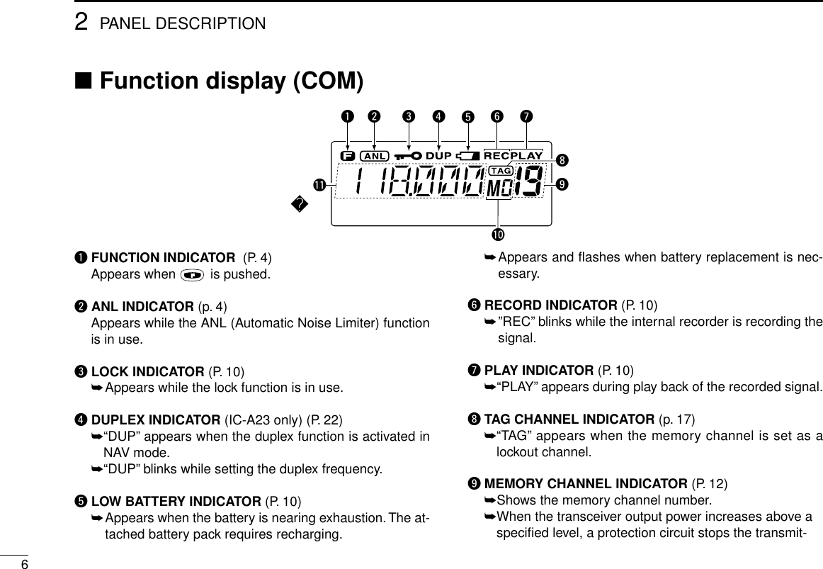
![72PANEL DESCRIPTIONting, then “--”appears on the display instead of thememory channel number. Release [PTT], then push itagain to continue transmitting.!0 MEMORY BANK NUMBER INDICATOR (p. 12)Shows the selected memory bank number.!1 FREQUENCY DISPLAY (P. 8)➥Shows the operating frequency.➥Shows the channel name when the memory name func-tion is selected.!2 COURSE INDICATORS (IC-A23 only) (P. 20)➥Indicates where your aircraft is located on a VOR radialin DVOR mode.➥Indicates where your desired course is located on aVOR radial in CDI mode.!3 TO-FROM INDICATOR (IC-A23 only) (P. 19)➥Indicates whether the VOR navigation information isbased on a course leading to the VOR station or lead-ing away from the VOR station.!4 COURSE DEVIATION NEEDLES (IC-A23 only) (P. 20)➥Indicates the deviation between the desired course andyour actual flying course every 2 degrees.!5 OVERFLOW INDICATOR (IC-A23 only) (P. 20)➥Appears when the deviation between the desired courseand flying course is over 10 degrees.!5!4!3!2■Function display (COM/NAV)](https://usermanual.wiki/ICOM-orporated/IC-A5/User-Guide-107377-Page-11.png)
![83BASIC OPERATION■DIAL↔[Y]/[Z] trade functionThe transceiver is equipped [DIAL]↔[Y]/[Z] keys trade func-tion. Push then push [CLR (DIAL/YZ)] to trade eachfunction.Default setting:DIAL: •Setting the frequency, •Selecting the memory chan-nel, •Selecting the bank numberYZ keys:•Increasing or decreasing the audio levelFollowing explanation is according to the default setting.■Setting a frequencyïUsing keypadqPush [PWR] for 0.5 sec. to turn power ON, then push[CLR] to select the frequency mode when memory CHnumber or WX CH number appears on the function display.wPush 5 appropriate digit keys to input the frequency.•Enter [1] as the 1st digit.• When a digit is mistakenly input, push [CLR] to clear,then start again.•Push [ENT] to enter consecutive zero digits.•Only [2], [5], [7] and [0] can be entered as the 5th andfinal digit.ïUsing the tuning dialqPush [PWR] for 0.5 sec. to turn power ON, then push[CLR] to select the VFO mode when memory CH numberor WX CH number appears on the function display.wRotate the [DIAL] to set the desired frequency.eTo select the 1 MHz tuning step, push , then rotate thetuning dial. Push again to return the normal tuning.■Accessing 121.5 MHz emer-gency frequencyThe IC-A23 and IC-A5 can quickly access the 121.5 MHzemergency frequency. This function can be activated evenwhen the key lock function is in use.qPush , then push [121.5] to call the emergency fre-quency.wPush [CLR] to exit from the emergency frequency.](https://usermanual.wiki/ICOM-orporated/IC-A5/User-Guide-107377-Page-12.png)
![■Selecting a weather channel (U.S.A. version only)The U.S.A. version has VHF marine WX (weather) channelreceiving capability for flight planning.qPush ,then push[ENT (WX)] to select WXchannel mode.•“WX--”and previously se-lected channel number ap-pears.wRotate the [DIAL] to select the desired WX channel.ePush [CLR] to exit the WX channel mode and return to fre-quency mode.■Setting squelch levelThe transceiver has a noise squelch circuit to mute undesirednoise while receiving no signal.DSetting the squelch levelqPush [SQL], then rotate the [DIAL] (or using [Y]/[Z]key)to select the squelch level.• ‘SQL--0’is loose squelch and ‘SQL--24’is tight squelch.•Rx indicator turns to green during the squelch is open.■Side tone functionWhen using an optional headset, such as those from theDavid Clark Co. via the OPC-967 HEAD SET ADAPTOR, thetransceiver outputs your transmitted voice to the headset formonitoring. (p. 30)DSetting the side tone levelqPush [PTT] to turn the transmit mode ON.wDuring transmit mode, rotate [DIAL] to adjust the monitor-ing level.• ‘ST--0’is OFF and ‘ST--15’is Max. level.NEVER operate the transceiver with a headset at high vol-ume levels for long period. A ringing in your ears may occur. Ifso, reduce the monitor level or discontinue use.■Beep toneThe beep tone which sounds each times a switch is pushedcan be adjusted, as desired.qPush , then push [BEEP].wTurn [DIAL] to adjust the beep level.93BASIC POPERATION](https://usermanual.wiki/ICOM-orporated/IC-A5/User-Guide-107377-Page-13.png)
![103BASIC OPERATION■Lock functionThe lock function prevents accidental frequency changes andaccidental function activation.qPush , then push [KEY LOCK] to turn the function ON.wTo turn the function OFF,repeat step qabove.•“ ”disappears.■Display backlightingPush [LIGHT] to turn the display backlighting ON or OFF.■Low battery indicatorLow battery indicator appears when the battery power hasdecreased to a specified level. The attached battery pack re-quires recharging.■REC/PLAY of recorded signals/messagesDRecording a signal/message➥Push , then push [ANL(REC)] to start to record thereceived message for 20sec.• ‘REC’blinks on the display.•Push [CLR] to cancel the recording.•No message is recorded when no audio comes from the speaker.(e.g. When the squelch is closed.)•You can record your own message when you start the recordingduring transmit mode.• Only the latest message is remains.DPlay➥Push , then push[BANK (PLAY)] to play backthe message.• ‘PLAY’appears on the dis-play.• Push [CLR] to cancel theplay back.•Play back the message during the transmit mode, you can trans-mit the recorded message.thenthenLow batteryindicator](https://usermanual.wiki/ICOM-orporated/IC-A5/User-Guide-107377-Page-14.png)
![113BASIC OPERATION■ReceivingqPush [PWR] to turn the power ON.wPush [SQL], then turn the [DIAL] counterclockwise (or [Z]key) to select the squelch level [0].ePush [Y]/[Z] key several times to adjust the audio level.rPush [SQL], then turn the [DIAL] clockwise (or [Y]key)until the noise is muted.•The Tx/Rx indicator disappears.tSet the desired frequency using the [DIAL] or keypad.yPush [ANL] to reduce pulse noise such as that caused byengine ignition systems, if necessary.•[ANL] appears on the display.uWhen a signal is received on the set frequency:• The Tx/Rx indicator lights green• Squelch opens and audio is emitted from the speaker.When the [SQL] control is too “deep”, squelch may not openfor weak signals.To receive weak signals, set the squelch to a“loose”position.■TransmittingqSet the desired frequency in COM band using the [DIAL]or keypad.•COM band frequency range: 118.00–136.975 MHzwPush and hold [PTT] to transmit.•The Tx/Rx indicator lights red.eSpeak into the microphone at a normal voice level.•DO NOT hold the transceiver too close to your mouth orspeak too loudly. This may distort the signal.rRelease [PTT] to return to receive.CAUTION: Transmitting without an antenna may damagethe transceiver.NOTE: To prevent interference, listen on the frequency be-fore transmitting. If the frequency is busy, wait until thechannel is clear.](https://usermanual.wiki/ICOM-orporated/IC-A5/User-Guide-107377-Page-15.png)
![124MEMORY OPERATION■Memory channel selectionThe transceiver has 200 memory channels for storage ofoften-used frequencies along with 6-character notes.qPush [MR] to select memory mode.•Memory BANK number and memory CH number appears.Using the [DIAL]:wPush [BANK], then rotate the [DIAL] to select the desiredmemory bank number, then push [CLR] (or [BANK]) to exitthe bank selection mode.• “BANK”appears.eRotate [DIAL] to select the desired memory CH number.•If no memory channel is programmed in the selected bank, nomemory CH selection is available.Using the Keypad:wPush [BANK], then push appropriate digit key (0 to 9) toselect the desired memory bank number, then push [CLR](or [BANK]) to exit the bank-selection mode.• “BANK”appears.ePush 2 appropriate digit key (00 to 19) to select the de-sired memory CH number.•If no memory channel is programmed in the selected bank, nomemory CH selection is available.Comments appear first when programmed, however, thetransceiver can be programmed by your dealer to showthe operating frequency first. Push [MR] to display thecomment in this case.■Transferring memorycontentsThis function transfers a memory channel’s contents into thefrequency mode. This is useful when searching for signalsaround a memory channel’s frequency.qPush [MR] to select memory mode.wSelect the desired memory channel to be transferred usingthe [DIAL] or keypad.ePush , then push [MR].•BANK number and memory CH number disappears asfrequency mode is automatically selected and the mem-ory contents are transferred.thenMemory mode Frequency mode](https://usermanual.wiki/ICOM-orporated/IC-A5/User-Guide-107377-Page-16.png)
![134MEMORY OPERATION■Programming a memorychannelThe transceiver has 200 (10 BANK x 20 CH) memory chan-nels for storage of often-used frequencies.qPush [CLR] to select Frequency mode, if necessary.wSelect the desired frequency.• Push , then push [ENT (WX)] to select a weather channel.*•Set the desired frequency or WX channel* using the [DIAL] orkeypad.ePush , then push [MR (MW)].•Memory BANK and memory channel number appears.rRotate the [DIAL] to select the desired memory channelnumber.•[M] blinks.•Push [BANK] to select the BANK number if desired. Push [CLR](or [BANK]) to exit the BANK selection mode.tPush [ENT] to program the information into the channeland return to Frequency mode.*Weather channel: U.S.A. version only.then [0], [5] or [5] [ENT]then[3][0], [2] or [2] then [ENT] or•EXAMPLE: Programming WX-05* into memory BANK 3/memory channel 2.](https://usermanual.wiki/ICOM-orporated/IC-A5/User-Guide-107377-Page-17.png)
![144MEMORY OPERATION■Memory namesïProgramming memory namesThe memory channel can display a 6-character comment aswell as a frequency.qRotate the [DIAL] to select the desired frequency in VFOmode.wPush ,then push [MR].eRotate the [DIAL] to select the desired memory channel tobe programmed.•Push [BANK] to select the BANK number if desired. Push [CLR]to exit the BANK selection mode.rPush [MR] to enter the memory name programming mode.•“-- -- -- -- -- -- ”appears on the display.tPush the appropriate digit key several times to select thedesired character as listed at right.•To erase a character, overwrite with a space (displayed as _).•To move the cursor forwards or backwards, use [DIAL].yPush [ENT] to program the name.•Flashing stops.•When no name is programmed, the display shows the operatingfrequency.•To clear the entered comment, push [CLR] before pushing [ENT].key Character 1 1, Q, Z4 4, G, H, I7 7, P, R, SENT Programkey Character2 2, A, B, C5 5, J, K, L8 8, T, U, V0 0, space, -key Character 3 3, D, E, F6 6, M, N, O9 9, W, X, YïClearing memory contentsUnwanted memory channels can be cleared. Programmingover a memory channel also clears the previously pro-grammed contents. Memory channel 0 cannot be cleared.qSelect the memory channel to be cleared.wPush , then push and hold [CLR] for 1 sec.•“-- -- -- -- -- --”appears momentarily, then the next selec-table channel appears.](https://usermanual.wiki/ICOM-orporated/IC-A5/User-Guide-107377-Page-18.png)
![154MEMORY OPERATION[CLR], [1], [2], [5], [ENT] [F], [MR(MW)] [1], [5](*see NOTE)[MR] [2], [2], [4], [4], [4], [4] [7], [7], [7][0], [0], [0],[2],[3] [ENT]•EXAMPLE: Programming 125.000 MHz into memory BANK 0/ memory channel 15with “AIR-23”as a comment.*NOTE: Push [BANK], then rotate the [DIAL] to select theBANK number, if desired. Push [CLR] to continue memoryname programming.](https://usermanual.wiki/ICOM-orporated/IC-A5/User-Guide-107377-Page-19.png)
![SCAN OPERATION516■Scan typesThe U.S.A. version has 3 scan types to suit your needs. Thenon-U.S.A. versions have 2 scan types.■COM band scanqPush [CLR] to select VFO mode.wSet squelch to the point where noise is just muted.ePush , then push [SQL (SCAN)] to start the scan.• When a signal is received, the scan pauses until it disap-pears.•To change the scanning direction, rotate the [DIAL].rTo stop the scan, push [CLR].■Memory scanqPush [MR] to select memory mode.wSet squelch to the point where noise is just muted.ePush , then push [SQL (SCAN)] to start the scan.• When a signal is received, the scan pauses until it disap-pears.•To change the scanning direction, rotate the [DIAL].rTo stop the scan, push [CLR].WEATHER CHANNEL SCANRepeatedly scans all “TAG”weather channels. Weatherchannels are available for the U.S.A. version only.MEMORY SCANRepeatedly scans all“TAG”memory channels.Used for checking often-used channels and by-passing usually busychannels such as control-tower frequencies..COM BAND SCANRepeatedly scans all fre-quencies over the entireCOM band. ScanJump108.00MHz 118.00MHz 136.975MHznon-TAGchannelnon-TAG channelMch 1 Mch 7Mch 2 Mch 4 Mch 6Mch 8Mch 19 Mch 10](https://usermanual.wiki/ICOM-orporated/IC-A5/User-Guide-107377-Page-20.png)
![5SCAN OPERATION17■Weather channel scan (U.S.A. version only)qPush , then push [ENT (WX)] to select a weatherchannel.wSet squelch to the point where noise is just muted.ePush , then push [SQL (SCAN)] to start the scan.• When a signal is received, the scan pauses until it disap-pears.•To change the scanning direction, rotate the [DIAL].rTo stop the scan, push [CLR].■“TAG” channelsMemory and weather* channels can be specified to beskipped for the memory and weather* channel scans respec-tively. The “TAG”channel function is only available during scanoperation.qPush [MR] to select memory mode; or, push , thenpush [ENT (WX)] to select a weather channel*.wSelect the desired channel to be a “TAG”channel.ePush , then push [9 (TAG)].•“TAG”appears.•Non-“TAG”channels are skipped during scan.rTo cancel the “TAG”setting, repeat above steps.*Weather channel: U.S.A. version only.Memory channel 19 isscanned during memoryscan.Memory channel 19 isskipped during scan.Shows the “TAG” channel. then](https://usermanual.wiki/ICOM-orporated/IC-A5/User-Guide-107377-Page-21.png)
![186VOR NAVIGATION (IC-A23 ONLY)■VOR indicators21434FROMCOM BAND(118.00–136.975 MHz)NAV BAND (108.00–117.975 MHz)DVOR MODEFunction display of the IC-A23General VOR equipmentTo-from flag indicatorCDI MODECourse indicatorCourseindicator Course deviation needlesOverflow indicatorPush [F] then [r CDI].Push [F] then [q DVOR].To-from flag indicatorCourse indicatorCourse deviation needleTo-from flag indicatorTwo-degree deviation marks](https://usermanual.wiki/ICOM-orporated/IC-A5/User-Guide-107377-Page-22.png)
![196VOR NAVIGATION■VOR functions◊To select CDI modeTo show the deviation between your flying course and the de-sired course, push , then [4 (CDI)].◊To select DVOR modeWhen entering the NAV band, 108.000–117.975 MHz, theIC-A23 selects DVOR mode automatically.To show your aircraft’s direction to (or from) the VOR station,push , then [1 (DVOR)].◊‘TO’or ‘FROM’flag selectionThe to-from flag indicators indicate whether the VOR naviga-tion information is based on a course leading to the VOR sta-tion or leading away from the VOR station.To change the flag from ‘TO’to ‘FROM’or vice versa, push, then [3 (FROM)] or [2 (TO)], respectively.•When using the ‘TO’flag and passing through the VORstation, the ‘TO’flag changes to the ‘FROM’flag automat-ically.•When turning power ON, the ‘FROM’flag is selected au-tomatically.◊Selecting the next VOR station when usingCDI mode (when using the course deviation needle)qPush , then [1 (DVOR)].wSet the next VOR station’s frequency.ePush , then [4 (CDI)].•Select ‘TO’or ‘FROM’flag, if desired.Operating frequency can be changed.Co rse indicator shows yo r directionCourse deviation needle does not appear.Operating frequency cannot be changed.Course indicator is fixed, but it can be changed with the tuning dial or keypad.Each course deviation arrow indicates a two-degree deviation.VOR NAVIGATION](https://usermanual.wiki/ICOM-orporated/IC-A5/User-Guide-107377-Page-23.png)
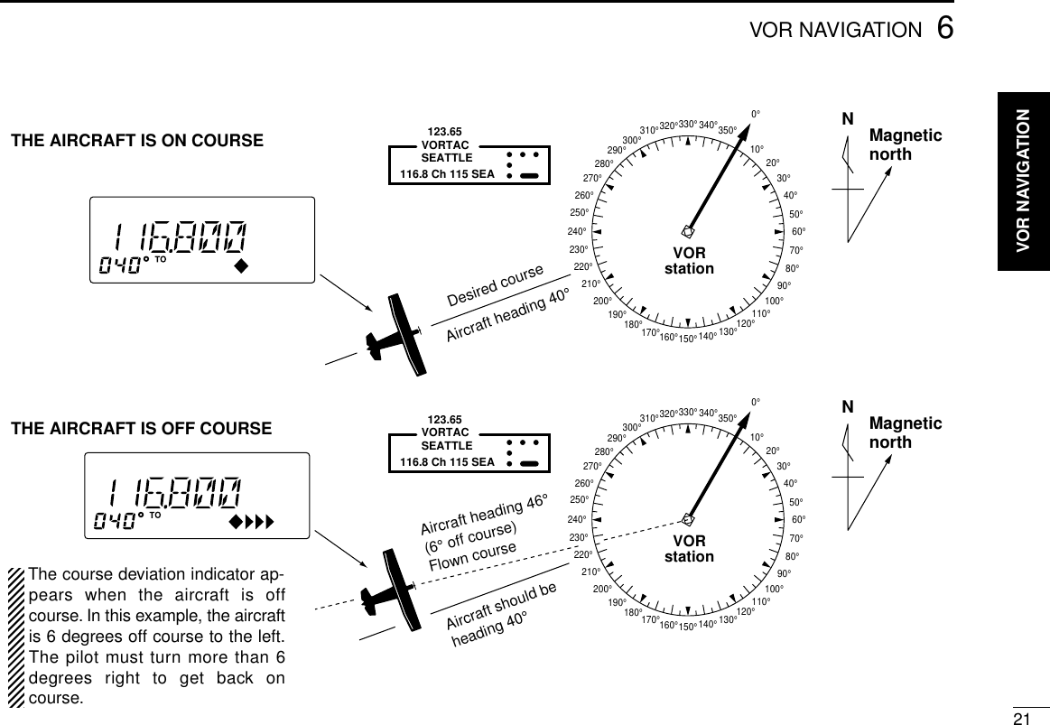
![206VOR NAVIGATION■Flying to a VOR stationThe IC-A23 shows the deviation from a VOR station.qSelect a VOR station on your aeronautical chart and setthe frequency of the station.•The course indicator indicates where you are located on a radialfrom the VOR station.•The course indicator shows ‘- - -’when either aircraft is too faraway from the VOR station or the frequency is not set correctly atthe VOR station.wSelect the ‘TO’flag when flying to the VOR station, or se-lect the ‘FROM’flag when flying away from the VOR sta-tion.•To select ‘TO,’push ,then [2 (TO)].•To select ‘FROM,’push ,then [3 (FROM)].ePush , then [4 (CDI)] to select CDI (Course DeviationIndicator) mode.•The course indicator shows ‘OFF’when the desired VOR signalcannot be received.When CDI mode is selected, the operating frequency can-not be changed. To set the operating frequency, selectDVOR mode in advance.rThe course deviation needle appears when your aircraft isoff course from the VOR station.•‘Ω’or ‘≈’appears to indicate your aircraft is off course to the rightor left, respectively. Correct your course until ‘Ω’or ‘≈’disappears.Each arrow represents a two-degree deviation.tTo exit CDI mode, push , then [1 (DVOR)].VOR INDICATOR NOTE‘LOC’appears on the function display as shown belowwhen a localizer signal is received.However, the function display does not indicate additionalinformation about the localizer signal.](https://usermanual.wiki/ICOM-orporated/IC-A5/User-Guide-107377-Page-24.png)
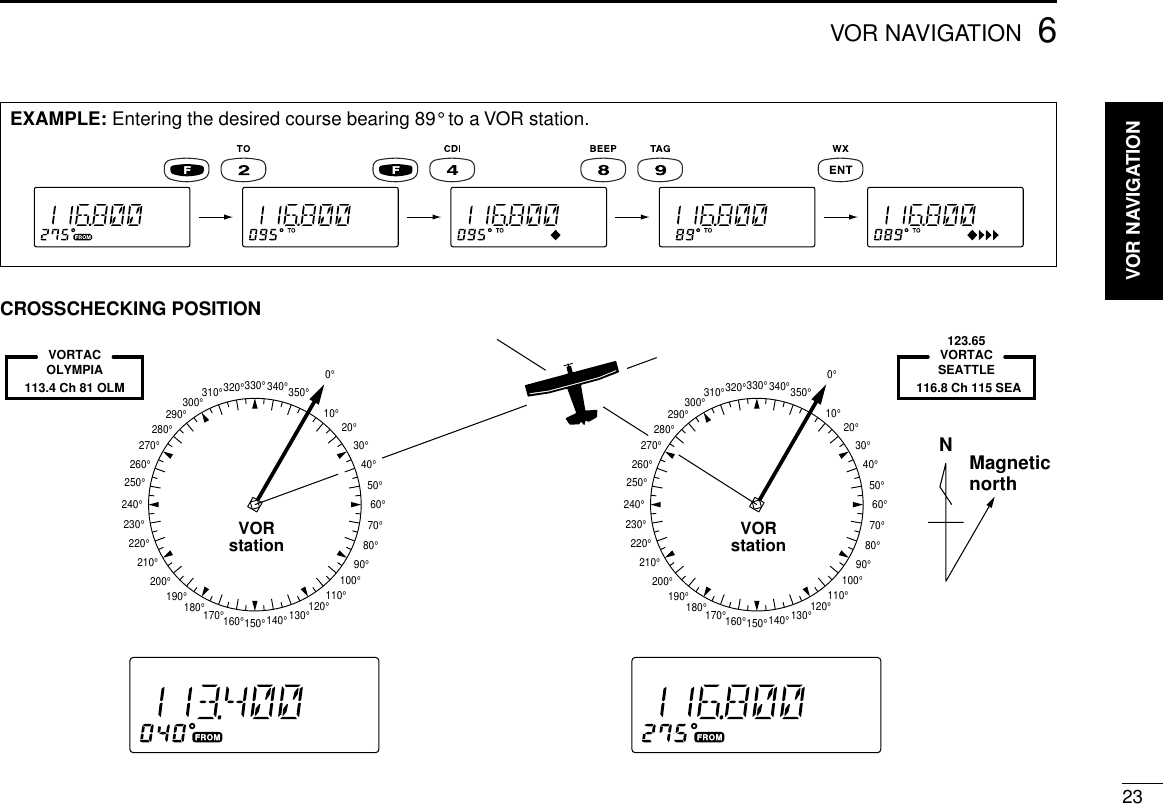
![226VOR NAVIGATION■Entering a desired courseThe IC-A23 shows not only the deviation from the VOR sta-tion but the deviation from the desired course.qSet the frequency for the desired VOR station.•To change the to-from flag, push ,then [2 (TO)] or [3(FROM)].wPush , then [4 (CDI)] to select CDI mode.eSet the desired course to the VOR station using the tuningdial or keypad.•‘Ω’or ‘≈’appears on the function display when your aircraft is offthe desired course.•When your heading is correct, the ABSS function may be usefulinstead of course input.rThe course deviation needle points to the right when youraircraft is off course to the left.•To get back on course, fly right more than the number of degreesindicated by the CDI arrows.•If the overflow indicator appears on the right side, select a head-ing plus 30 degrees to the desired course; if the overflow indica-tor appears on the left side, select a heading minus 30 degrees.■Crosschecking positionqSelect 2 VOR stations on your aeronautical chart.wSet the frequency of one of the VOR station in DVORmode.•The course indicator shows course deviation from the VOR ra-dial. Note the radial you are on.eSet the frequency of the other VOR station in DVOR mode.•Note the radial from the station you are on.rExtend the radials from each VOR station on the chart.Your aircraft is located at the point where the lines inter-sect.ABSS FUNCTIONIn CDI mode, the Auto Bearing Set System (ABSS) addsor subtracts the number of degrees indicated by the CDIarrows from the Omni Bearing Selector (OBS).To use ABSS, push , then [2 (TO)] while using the ‘TOflag; or, push , then [3 (FROM)] while using the ‘FROM’flag.](https://usermanual.wiki/ICOM-orporated/IC-A5/User-Guide-107377-Page-26.png)
![246VOR NAVIGATION■Duplex operation (U.S.A. version only)The duplex function allows you to call a flight service stationwhile receiving a VOR station. The duplex function requiresfrequency programming for the flight service station in ad-vance.◊Programming a duplex frequencyqPush [CLR] to select frequency mode.wSet a NAV band frequency using the tuning dial or keypad.•NAV band frequency range: 108.00–117.975 MHzePush , then [5 (DUP-W)].•“DUP”flashes and transmit frequency appears.rSet the frequency of the flight service station using the tun-ing dial or keypad. When using the tuning dial, push [ENT]after setting a frequency.•The displayed frequency returns to the NAV band frequency.◊Operating the duplex functionqSet the desired frequency in NAV band.•NAV band frequency range: 108.00–117.975 MHzwPush , then [6 (DUP)] to turn the duplex function ON.•“DUP”appears on the function display.ePush and hold [PTT] to transmit at the pre-programmedtransmit frequency.rRelease [PTT] to return to receive.tPush , then [6 (DUP)] to cancel the function.A duplex frequency can be programmed into each mem-ory channel independently. Set a duplex frequency beforeprogramming the memory channel, if desired. The duplexON/OFF setting can also be programmed into a memorychannel.EXAMPLE: Programming 123.65 MHz as the transmit frequency in the duplex function.](https://usermanual.wiki/ICOM-orporated/IC-A5/User-Guide-107377-Page-28.png)
![267BATTERY PACKSDRapid charging with the 119 DRegular chargingqAttach the battery pack to the transceiver.wBe sure to turn the transceiver power OFF.eConnect the Wall charger (BC-110A) or optional cable(CP-12L or OPC-254L) as shown below.•Charging period: 10 hours IC-A23/A5 withattachedbattery caseWall chargerCP-12L(optional)OPC-254L(optional)To a 12 to 14 V DCpower sourceTo[CHARGE]whiteblack*AD-87B(supplied with AD-87A)AD-88(optional)Check orientationfor correct chargingAD-87A(optional)BC-119(optional)*](https://usermanual.wiki/ICOM-orporated/IC-A5/User-Guide-107377-Page-30.png)
![288CLONINGCloning allows you to quickly and easily transfer theprogrammed contents from one transceiver to anothertransceiver, or, data from PC to a transceiver using theoptional CS-A23 cloning software.DTransceiver to transceiver cloningqConnect the OPC-474 CLONING CABLE with adapter plugs tothe [SP/MIC] jack of the master and slave transceivers.•The master transceiver is used to send data to the slave trans-ceiver.wWhile push and holding [Y] + [Z],push [PWR] ON to entercloning mode (for both the master transceiver and slavetransceiver both.).•“CLONE”appears and the transceivers enter the clonestandby condition.ePush [PTT] on the mastertransceiver.•“CL-OUT”appears in themaster transceiver’s display.•“CL-IN”appears automati-cally in the slave trans-ceiver’s display.rWhen cloning is finished,turn power OFF, then ONagain to exit cloning mode.DCloning using PCData can be cloned to and from a PC (IBM compatible) usingthe optional CS-A23 CLONING SOFTWARE and the optional OPC-478 CLONING CABLE. Consult the CS-A23 CLONING SOFTWARE HELPmessage for details.DCloning errorNOTE: DO NOT push [PTT] on the slave transceiver dur-ing cloning. This will cause a cloning error.When the display at right ap-pears, a cloning error has oc-curred.In this case, both transceivers automatically return to theclone standby condition and cloning must be repeated.](https://usermanual.wiki/ICOM-orporated/IC-A5/User-Guide-107377-Page-32.png)
![9TROUBLESHOOTING29If your transceiver seems to be malfunctioning, please checkthe following points before sending it to a service center.POSSIBLE CAUSE SOLUTION REF.No power comes on. •The battery is exhausted.•Bad connection for the battery pack.•Recharge the battery pack.•Check the connection to thetransceiver.pgs. 23,25No sound comes from thespeaker.•Squelch level is too deep.•Volume level is too low.•Set squelch to the threshold point.•Set [VOL] to a suitable level.pgs. 9, 10Transmitting impossible. •Some channels are receive only.•The battery is exhausted.•Change channels.•Recharge the battery pack.p. 8p. 23The displayed channelcannot be selected.•Lock function is activated. •Push [F], then push [7 (KEY LOCK)]. p. 10Scan does not start. •All memory channels are not programmed as “TAG” channels.•Set the “TAG” settings of desired channels.p. 16No beep sounds. •Beep tones turned OFF. •Push [F], then push [8 (BEEP)] to adjust the beep tone level. p. 9PROBLEM](https://usermanual.wiki/ICOM-orporated/IC-A5/User-Guide-107377-Page-33.png)