ICOM orporated IC-A5 Handheld Aircraft Transmitter with VOR Navigation User Manual Manual
ICOM Incorporated Handheld Aircraft Transmitter with VOR Navigation Manual
Manual

iA23
iA5
VHF AIR BAND TRANSCEIVER
INSTRUCTION MANUAL
This device complies with Part 15 of the FCC rules. Operation is sub-
ject to the following two conditions: (1) This device may not cause
harmful interference, and (2) this device must accept any interference
received, including interference that may cause undesired operation.

i
FOREWORD
READ ALL INSTRUCTIONS carefully and completely
before using the transceiver.
SAVE THIS INSTRUCTION MANUAL—This in-
struction manual contains important operating instructions for
the IC-A23/A5.
EXPLICIT DEFINITIONS
The explicit definitions below apply to this instruction manual.
CAUTION
RWARNING! NEVER hold the transceiver so that the
antenna is very close to, or touching exposed parts of the
body, especially the face or eyes, while transmitting. The
transceiver will perform best if the microphone is 5 to 10 cm
away from the lips and the transceiver is vertical.
RWARNING! NEVER operate the transceiver with a
headset or other audio accessories at high volume levels.
Hearing experts advise against continuous high volume op-
eration. If you experience a ringing in your ears, reduce the
volume level or discontinue use.
NEVER connect the transceiver to an AC outlet or to a
power source of more than 14 V DC. Such a connection will
damage the transceiver.
NEVER connect the transceiver to a power source that is
DC fused at more than 5 A. Accidental reverse connection will
be protected by this fuse, higher fuse values will not give any
protection against such accidents and the transceiver will be
ruined.
NEVER short the terminals of the battery pack. Also, cur-
rent may flow into nearby metal objects, such as a necklace,
WORD DEFINITION
RWARNING Personal injury, fire hazard or electric shock
may occur.
CAUTION Equipment damage may occur.
NOTE Inconvenience only. No risk of personal
injury, fire or electric shock.
FCC caution: Changes or modifications to this transceiver, not
expressly approved by Icom Inc., could void your authority to
operate this transceiver under FCC regulations. (U.S.A. only)

ii
etc. Therefore, be careful when carrying with, or placing near
metal objects, carrying in handbags, etc.
DO NOT allow children to play with any radio equipment
containing a transmitter.
DO NOT operate the transceiver near unshielded electrical
blasting caps or in an explosive atmosphere.
AVOID using or placing the transceiver in direct sunlight or
in areas with temperatures below –10°C (+14°F) or above
+60°C (+140°F).
The use of non-Icom battery packs/chargers may impair
transceiver performance and invalidate the warranty.
Even when the transceiver power is OFF, a slight current still
flows in the circuits. Remove the battery pack or case from
the transceiver when not using it for a long time. Otherwise,
the battery pack or installed dry cell batteries will become ex-
hausted.
SUPPLIED ACCESSORIES
Accessories included with the transceiver: Qty.
qAntenna........................................................................... 1
wBelt clip............................................................................ 1
eBattery pack (BP-200L)*.................................................. 1
rWall charger* .................................................................. 1
•Carrying case (LC-147)* ............................................... 1
•HEADSET ADAPTER (OPC-967)* ............................... 1
*The battery pack, wall charger, HEADSET ADAPTER or carry-
ing case may differ depending on version. Some versions do not
include a battery pack, wall charger, HEADSET ADAPTER or
carrying case.
qw
e
r

FOREWORD .................................................................................... i
EXPLICIT DEFINITIONS ................................................................. i
CAUTIONS ....................................................................................... i
SUPPLIED ACCESSORIES............................................................. ii
TABLE OF CONTENTS .................................................................. iii
1 ACCESSORY ATTACHMENT .................................................. 1
2 PANEL DESCRIPTION ........................................................ 2–7
■Panel description ............................................................... 2–5
■Function display ................................................................ 6–7
3 BASIC OPERATION ............................................................ 8 –7
■DIAL↔[Y]/[Z] trade function ...................................................8
■Setting a frequency ................................................................ 8
■Lock function .......................................................................... 8
■Accessing 121.5 MHz emergency frequency ......................... 8
■Setting a squelch level ........................................................... 9
■Side tone function .................................................................. 9
■Display backlighting ............................................................... 9
■Low battery indicator .............................................................. 9
■Receiving ............................................................................. 10
■Transmitting .......................................................................... 10
■Selecting a weather channel................................................. 11
■Side tone function .................................................................. 6
■Lock function .......................................................................... 6
■Display backlighting ............................................................... 6
■Low battery indicator .............................................................. 6
■Dial select function ................................................................. 7
4 MEMORY OPERATION .......................................................... 12
■Memory channel selection ................................................... 12
■Transferring memory contents ............................................. 12
■Programming a memory channel ......................................... 13
■Memory names .................................................................... 14
5 SCAN OPERATION ................................................................ 16
■Scan types ........................................................................... 16
■COM band scan ................................................................... 16
■Memory scan ....................................................................... 16
■Weather channel scan ......................................................... 17
■“TAG” channels ................................................................... 17
6 VOR NAVIGATION (IC-A23 only) .................................... 18– 24
■VOR indications ................................................................... 18
■VOR functions ...................................................................... 19
■Flying to a VOR station ........................................................ 20
■Entering a desired course .................................................... 22
■Crosschecking position ........................................................ 22
■Duplex operation ................................................................. 24
7 BATTERY PACKS ........................................................... 25– 27
■Charging precautions ........................................................... 25
■Battery pack charging .......................................................... 25
■About the battery pack ......................................................... 27
■IBattery pack CAUTION ....................................................... 27
8 CLONING ................................................................................ 28
9 TROUBLESHOOTING ............................................................ 29
10 SPECIFICATIONS .................................................................. 30
11 OPTIONS ................................................................................ 31
■OPC-967 connection ............................................................ 32
iii
TABLE OF CONTENTS
1
1
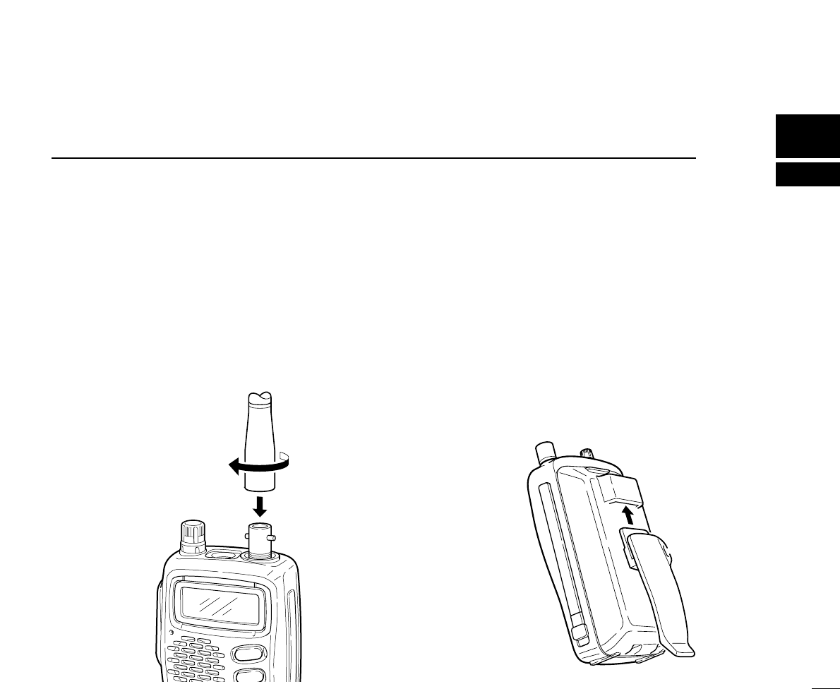
ACCESSORY ATTACHMENT
DAntenna
CAUTION: Transmitting without an antenna may damage
the transceiver.
Insert the supplied antenna into the antenna connector and
screw down the antenna as shown below.
Keep the jack cover attached when jacks are not in use to
avoid bad contacts from dust and moisture.
DBelt clip
Conveniently attaches to your belt.
To attach:
Slide the belt clip into the plastic loop on the back of the bat-
tery case/pack.
To remove:
Push the top of the belt clip towards the transceiver and at
the same time, push it downward and free of the plastic loop.
2
2PANEL DESCRIPTION
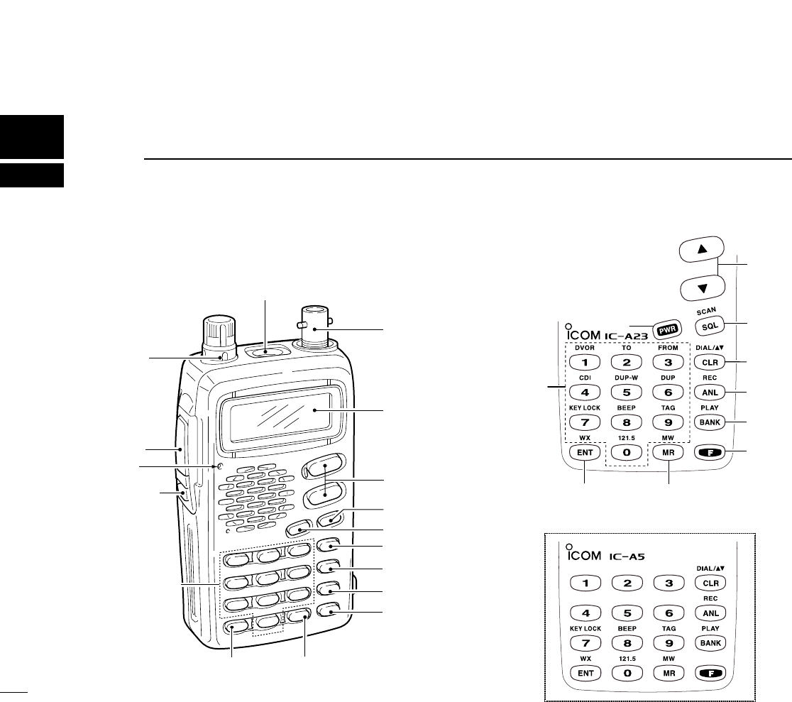
■Panel description
e[DIAL]
r[MIC/SP]
w[PTT]
t[ANT]
!0[CLR(DIAL/ÙÚ)]
!1[ANL(REC)]
!2[BANK(PLAY)]
!3[FUNCTION]
!4[MR(MW)]
!5[ENT(WX)]
q[LIGHT]
yDisplay
u[UP/DOWN]
i[SQL(SCAN)]
Tx/Rx
indicator
!6[DIGIT KEYS]
o[PWR]
u
i
!0
!1
!2
!3
!4
!5
o
!6
3
2
PANEL DESCRIPTION
qLIGHT [LIGHT] (p. 10)
Turns the light for display and keypad ON or OFF.
wPTT SWITCH [PTT] (p. 11)
Push and hold to transmit; release to receive.
eTUNING DIAL [DIAL] (P. 8)
➥Rotate [DIAL] to select the desired frequency. (default)
➥Rotate [DIAL] to select the BANK number. (default)
➥Rotate [DIAL] to select the memory channel or WX
channel number. (default)
➥Rotate [DIAL] to adjust the audio level.
rEXTERNAL SPEAKER AND MICROPHONE JACKS
MIC/SP] (pgs. 29, 30)
Connect an optional speaker-microphone or headset, if de-
sired.The internal microphone will not function when either
is connected.
tANTENNA CONNECTOR [ANT]
Connects the supplied antenna.
yFUNCTION DISPLAY (pgs. 6, 7)
uUP/DOWN KEYS [Y]/[Z] (P. 8)
➥Push [Y] to increase the audio level, push [Z] to
decrease the audio level. (default)
➥Push to select the operating channel or fre-
quency.
➥Push to select the BANK number.
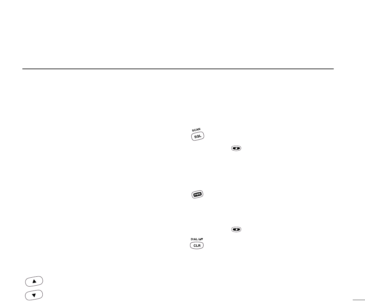
iSQUELCH KEY [SQL] (P. 9)
➥Push [SQL], then rotate the [DIAL] (or push
[Y]/[Z]) to select the squelch level.
• 24 squelch levels and squelch open (0) are available.
➥Push , then push [SQL] to starts scan func-
tion:
Frequency mode: Frequency full scan function.
MEMORY mode: Memory channel scan function.
oPOWER SWITCH [PWR]
➥Push and hold for 0.5 sec. to turn the power ON
or OFF.
➥While pushing [Y]/[Z], push [PWR] to enter the
cloning function mode.
!0 CLR KEY [CLR]
➥Push , then push [CLR] to exchange the e
tuning Dial function and uUP [Y]/DOWN [Z]
switch function;
- Dial: tuning (default)
- UP[Y]/DOWN[Z]: audio level setting (default)
NOTE: You can adjust the audio level via [DIAL]
and select the frequency, memory channel or
BANK number via UP[Y]/DOWN[Z] keys.
➥Push [CLR] to turn to the frequency mode, when
memory channel, WX channel or 121.5 MHz is
selected.
4
2PANEL DESCRIPTION
!0 CLR KEY [CLR] (continue)
➥Push [CLR] to cancel the SCAN function.
➥Push [CLR] to cancel the direct frequency enter-
ing with digit key.
➥Push [CLR] to turn the squelch level adjusting
mode OFF.
!1 ANL KEY [ANL]
➥Push to turn the ANL function ON or OFF.
➥Push , then push [ANL (REC)] to turn the
recording function ON.
- The transceiver records the receiving signal or opera-
tors voice for 20 sec.
!2 BANK KEY [BANK] (P. 12)
➥Push [BANK] to enter the BANK selection mode
while memory channel is selected, push [CLR]
to exit the BANK selection mode.
➥Push , then push [BANK] to play the
recorded signals.
!3 FUNCTION KEY [F]
Push to call up the function indicator, “”, then
push another key to access its secondary function.
•“ ” appears for 3 sec. after [F] is pushed; at this time
pushing [F] again cancels the indication. (P. 6)
•This key cannot activate during transmit.
NOTE: In general, “”disappears when another key is
pushed to activate a secondary function. However, some keys
which have more than one secondary function, (such as
[DUP]), do not cancel “”. In this case, “”disappears auto-
matically after 3 sec.
!4 MEMORY MODE KEY [MR (MW)] (P. 12)
➥Push [MR] to call the memory channel mode,
push [CLR] to exit the memory channel mode.
➥Push , then push [MR (MW)] to program the
contents into the memory channels.
➥Push [MR] to program the memory comment
when the memory comment function is enabled.
!5 ENTER KEY [ENT(WX)] (P. 8)
➥Push [ENT] to enter the numeral input. Enters
consecutive zero digits.
➥Push , then push [ENT] to enter the weather
channel selection mode. (U.S.A. version only)
•Rx/Tx indicator
➥Lights red during the transmit mode.
➥Lights green during receiving a signal or squelch is
open.
NOTE: Some functions may not be available depending on
version. Please consult your dealer.
5
2
PANEL DESCRIPTION
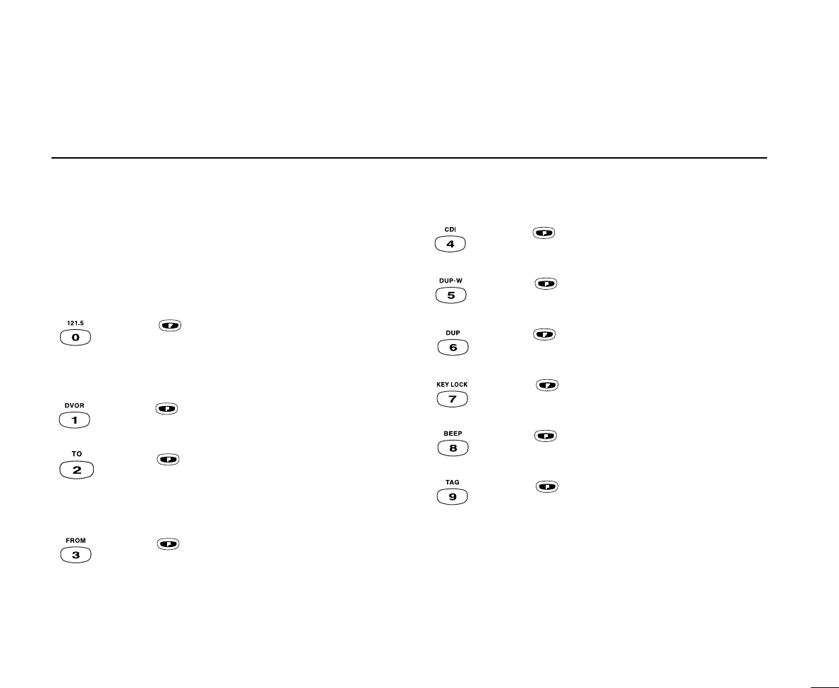
!6 DIGIT KEYS
➥Input the specified digit during frequency input, memory
channel selection, etc.
➥In addition, each key has one or more secondary func-
tions after pushing [F] as follows:
➥Push , then push [0] to select the 121.5
MHz emergency frequency. (P. 8)
➥Push [CLR] to cancel the direct frequency enter-
ing with digit key.
➥Push , then push [1] to select the DVOR dis-
play from the CDI display in NAV band. (P. 19)*1
➥Push , then push [2] to change the course
indicator characteristics to “TO”flag in the DVOR
display in NAV band. (P. 19)*1
➥Corrects the deviation while using “TO”flag. *1
➥Push , then push [3] to change the course
indicator characteristics to “FROM”flag in the
DVOR display in NAV band. (P. 19)*1
➥Corrects the deviation while using “FROM”flag.
*1
➥Push , then push [4] to select the CDI dis-
play from the CDI display in NAV band. (P. 19)*1
➥Push , then push [5] to set the duplex fre-
quency in NAV band. (P. 22)*1
➥Push , then push [6] to turn the duplex func-
tion ON and OFF in NAV band. (P. 22)*1
➥Push , then push [7] to turn the key lock
function ON and OFF. (P. 10)
➥Push , then push [8] to Turn the beep tone
ON and OFF. (P. 9)
➥Push , then push [9] to set the displayed
memory or weather channel as a “TAG”channel.
(P. 17)
*1These functions available on the IC-A23 only.
6
2PANEL DESCRIPTION
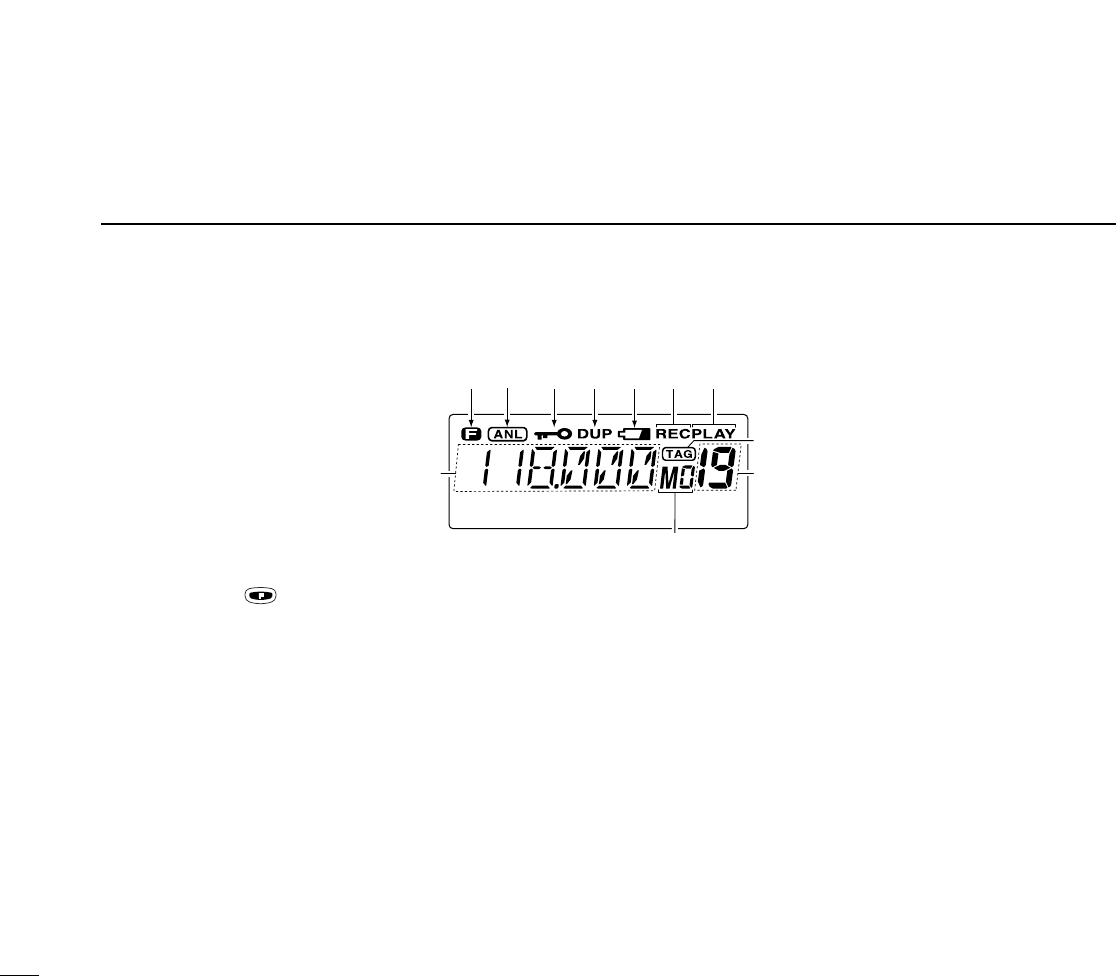
■Function display (COM)
qFUNCTION INDICATOR (P. 4)
Appears when is pushed.
wANL INDICATOR (p. 4)
Appears while the ANL (Automatic Noise Limiter) function
is in use.
eLOCK INDICATOR (P. 10)
➥Appears while the lock function is in use.
rDUPLEX INDICATOR (IC-A23 only) (P. 22)
➥“DUP”appears when the duplex function is activated in
NAV mode.
➥“DUP”blinks while setting the duplex frequency.
tLOW BATTERY INDICATOR (P. 10)
➥Appears when the battery is nearing exhaustion. The at-
tached battery pack requires recharging.
➥Appears and flashes when battery replacement is nec-
essary.
yRECORD INDICATOR (P. 10)
➥”REC”blinks while the internal recorder is recording the
signal.
uPLAY INDICATOR (P. 10)
➥“PLAY”appears during play back of the recorded signal.
iTAG CHANNEL INDICATOR (p. 17)
➥“TAG”appears when the memory channel is set as a
lockout channel.
oMEMORY CHANNEL INDICATOR (P. 12)
➥Shows the memory channel number.
➥When the transceiver output power increases above a
specified level, a protection circuit stops the transmit-
yu
!1
t
!0
o
re
w
q
i
7
2
PANEL DESCRIPTION
ting, then “--”appears on the display instead of the
memory channel number. Release [PTT], then push it
again to continue transmitting.
!0 MEMORY BANK NUMBER INDICATOR (p. 12)
Shows the selected memory bank number.
!1 FREQUENCY DISPLAY (P. 8)
➥Shows the operating frequency.
➥Shows the channel name when the memory name func-
tion is selected.
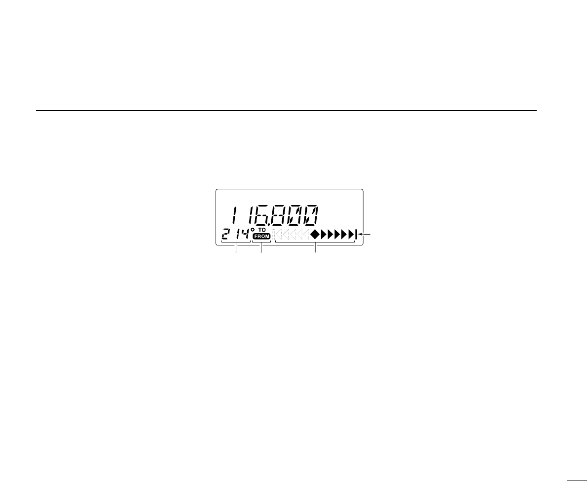
!2 COURSE INDICATORS (IC-A23 only) (P. 20)
➥Indicates where your aircraft is located on a VOR radial
in DVOR mode.
➥Indicates where your desired course is located on a
VOR radial in CDI mode.
!3 TO-FROM INDICATOR (IC-A23 only) (P. 19)
➥Indicates whether the VOR navigation information is
based on a course leading to the VOR station or lead-
ing away from the VOR station.
!4 COURSE DEVIATION NEEDLES (IC-A23 only) (P. 20)
➥Indicates the deviation between the desired course and
your actual flying course every 2 degrees.
!5 OVERFLOW INDICATOR (IC-A23 only) (P. 20)
➥Appears when the deviation between the desired course
and flying course is over 10 degrees.
!5
!4
!3!2
■Function display (COM/NAV)

8
3BASIC OPERATION
■DIAL↔[Y]/[Z] trade function
The transceiver is equipped [DIAL]↔[Y]/[Z] keys trade func-
tion. Push then push [CLR (DIAL/YZ)] to trade each
function.
Default setting:
DIAL: •Setting the frequency, •Selecting the memory chan-
nel, •Selecting the bank number
YZ keys:•Increasing or decreasing the audio level
Following explanation is according to the default setting.
■Setting a frequency
ïUsing keypad
qPush [PWR] for 0.5 sec. to turn power ON, then push
[CLR] to select the frequency mode when memory CH
number or WX CH number appears on the function display.
wPush 5 appropriate digit keys to input the frequency.
•Enter [1] as the 1st digit.
• When a digit is mistakenly input, push [CLR] to clear,
then start again.
•Push [ENT] to enter consecutive zero digits.
•Only [2], [5], [7] and [0] can be entered as the 5th and
final digit.
ïUsing the tuning dial
qPush [PWR] for 0.5 sec. to turn power ON, then push
[CLR] to select the VFO mode when memory CH number
or WX CH number appears on the function display.
wRotate the [DIAL] to set the desired frequency.
eTo select the 1 MHz tuning step, push , then rotate the
tuning dial. Push again to return the normal tuning.
■Accessing 121.5 MHz emer-
gency frequency
The IC-A23 and IC-A5 can quickly access the 121.5 MHz
emergency frequency. This function can be activated even
when the key lock function is in use.
qPush , then push [121.5] to call the emergency fre-
quency.
wPush [CLR] to exit from the emergency frequency.

■Selecting a weather channel
(U.S.A. version only)
The U.S.A. version has VHF marine WX (weather) channel
receiving capability for flight planning.
qPush ,then push
[ENT (WX)] to select WX
channel mode.
•“WX--”and previously se-
lected channel number ap-
pears.
wRotate the [DIAL] to select the desired WX channel.
ePush [CLR] to exit the WX channel mode and return to fre-
quency mode.
■Setting squelch level
The transceiver has a noise squelch circuit to mute undesired
noise while receiving no signal.
DSetting the squelch level
qPush [SQL], then rotate the [DIAL] (or using [Y]/[Z]key)
to select the squelch level.
• ‘SQL--0’is loose squelch and ‘SQL--24’is tight squelch.
•Rx indicator turns to green during the squelch is open.
■Side tone function
When using an optional headset, such as those from the
David Clark Co. via the OPC-967 HEAD SET ADAPTOR, the
transceiver outputs your transmitted voice to the headset for
monitoring. (p. 30)
DSetting the side tone level
qPush [PTT] to turn the transmit mode ON.
wDuring transmit mode, rotate [DIAL] to adjust the monitor-
ing level.
• ‘ST--0’is OFF and ‘ST--15’is Max. level.
NEVER operate the transceiver with a headset at high vol-
ume levels for long period. A ringing in your ears may occur. If
so, reduce the monitor level or discontinue use.
■Beep tone
The beep tone which sounds each times a switch is pushed
can be adjusted, as desired.
qPush , then push [BEEP].
wTurn [DIAL] to adjust the beep level.
9
3
BASIC POPERATION
10
3BASIC OPERATION
■Lock function
The lock function prevents accidental frequency changes and
accidental function activation.
qPush , then push [KEY LOCK] to turn the function ON.
wTo turn the function OFF,repeat step qabove.
•“ ”disappears.
■Display backlighting
Push [LIGHT] to turn the display backlighting ON or OFF.
■Low battery indicator
Low battery indicator appears when the battery power has
decreased to a specified level. The attached battery pack re-
quires recharging.
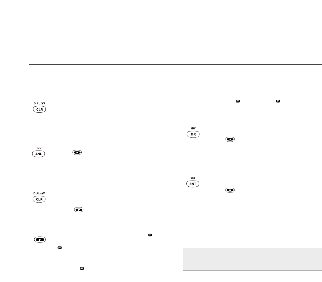
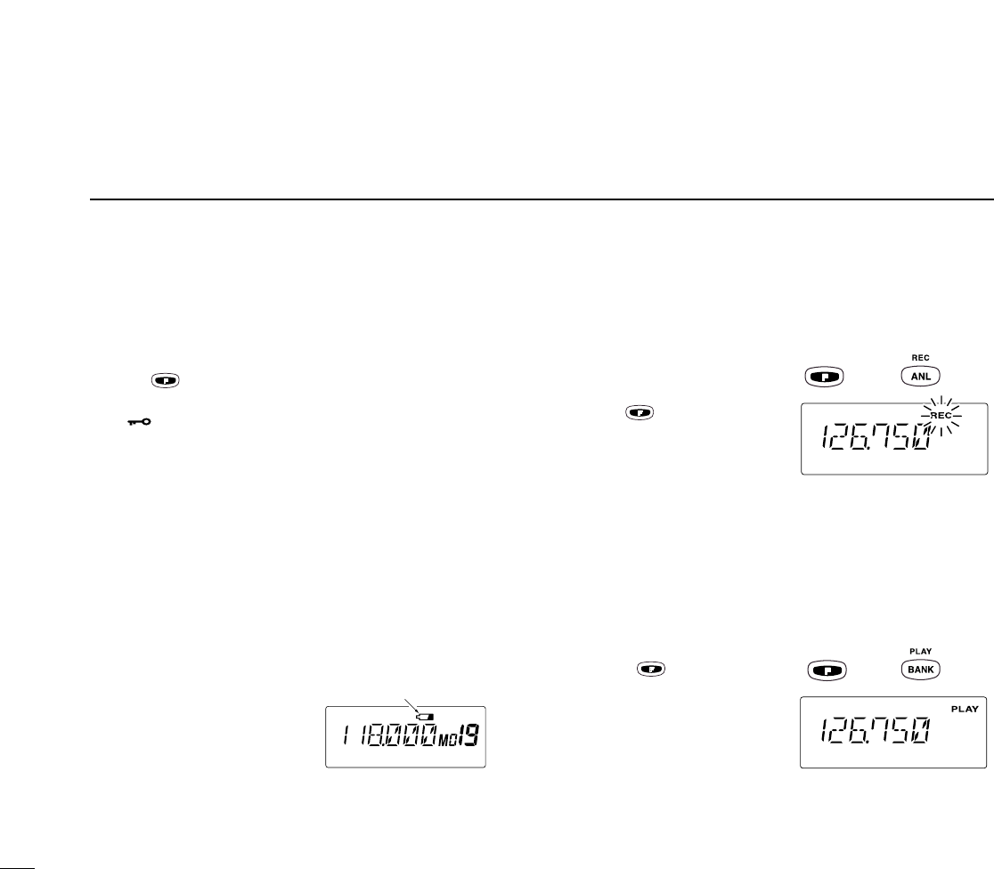
■REC/PLAY of recorded signals
/messages
DRecording a signal
/message
➥Push , then push [ANL
(REC)] to start to record the
received message for 20
sec.
• ‘REC’blinks on the display.
•Push [CLR] to cancel the recording.
•No message is recorded when no audio comes from the speaker.
(e.g. When the squelch is closed.)
•You can record your own message when you start the recording
during transmit mode.
• Only the latest message is remains.
DPlay
➥Push , then push
[BANK (PLAY)] to play back
the message.
• ‘PLAY’appears on the dis-
play.
• Push [CLR] to cancel the
play back.
•Play back the message during the transmit mode, you can trans-
mit the recorded message.
then
then
Low battery
indicator

11
3
BASIC OPERATION
■Receiving
qPush [PWR] to turn the power ON.
wPush [SQL], then turn the [DIAL] counterclockwise (or [Z]
key) to select the squelch level [0].
ePush [Y]/[Z] key several times to adjust the audio level.
rPush [SQL], then turn the [DIAL] clockwise (or [Y]key)
until the noise is muted.
•The Tx/Rx indicator disappears.
tSet the desired frequency using the [DIAL] or keypad.
yPush [ANL] to reduce pulse noise such as that caused by
engine ignition systems, if necessary.
•[ANL] appears on the display.
uWhen a signal is received on the set frequency:
• The Tx/Rx indicator lights green
• Squelch opens and audio is emitted from the speaker.
When the [SQL] control is too “deep”, squelch may not open
for weak signals.To receive weak signals, set the squelch to a
“loose”position.
■Transmitting
qSet the desired frequency in COM band using the [DIAL]
or keypad.
•COM band frequency range: 118.00–136.975 MHz
wPush and hold [PTT] to transmit.
•The Tx/Rx indicator lights red.
eSpeak into the microphone at a normal voice level.
•DO NOT hold the transceiver too close to your mouth or
speak too loudly. This may distort the signal.
rRelease [PTT] to return to receive.
CAUTION: Transmitting without an antenna may damage
the transceiver.
NOTE: To prevent interference, listen on the frequency be-
fore transmitting. If the frequency is busy, wait until the
channel is clear.
12
4MEMORY OPERATION
■Memory channel selection
The transceiver has 200 memory channels for storage of
often-used frequencies along with 6-character notes.
qPush [MR] to select memory mode.
•Memory BANK number and memory CH number appears.
Using the [DIAL]:
wPush [BANK], then rotate the [DIAL] to select the desired
memory bank number, then push [CLR] (or [BANK]) to exit
the bank selection mode.
• “BANK”appears.
eRotate [DIAL] to select the desired memory CH number.
•If no memory channel is programmed in the selected bank, no
memory CH selection is available.
Using the Keypad:
wPush [BANK], then push appropriate digit key (0 to 9) to
select the desired memory bank number, then push [CLR]
(or [BANK]) to exit the bank-selection mode.
• “BANK”appears.
ePush 2 appropriate digit key (00 to 19) to select the de-
sired memory CH number.
•If no memory channel is programmed in the selected bank, no
memory CH selection is available.
Comments appear first when programmed, however, the
transceiver can be programmed by your dealer to show
the operating frequency first. Push [MR] to display the
comment in this case.
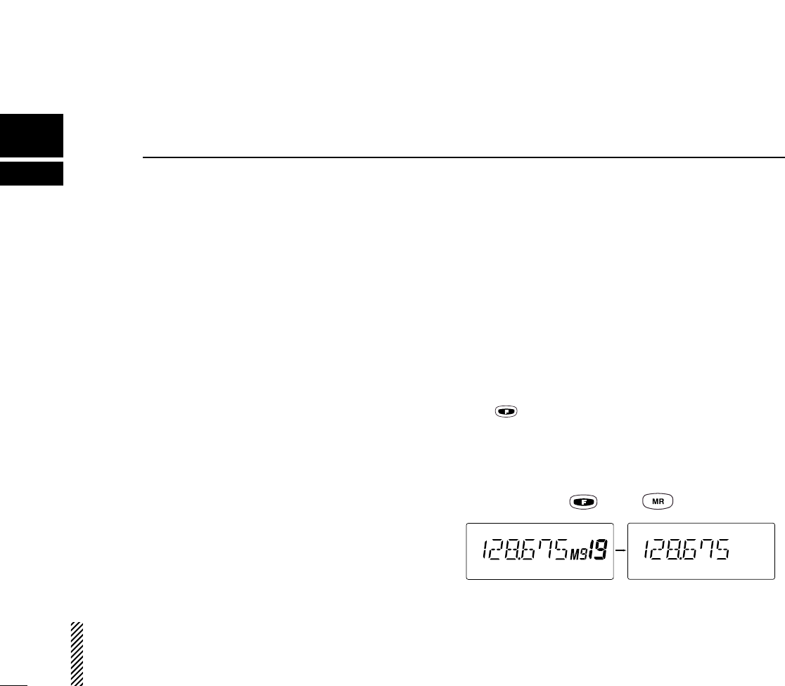
■Transferring memory
contents
This function transfers a memory channel’s contents into the
frequency mode. This is useful when searching for signals
around a memory channel’s frequency.
qPush [MR] to select memory mode.
wSelect the desired memory channel to be transferred using
the [DIAL] or keypad.
ePush , then push [MR].
•BANK number and memory CH number disappears as
frequency mode is automatically selected and the mem-
ory contents are transferred.
then
Memory mode Frequency mode
13
4
MEMORY OPERATION
■Programming a memory
channel
The transceiver has 200 (10 BANK x 20 CH) memory chan-
nels for storage of often-used frequencies.
qPush [CLR] to select Frequency mode, if necessary.
wSelect the desired frequency.
• Push , then push [ENT (WX)] to select a weather channel.*
•Set the desired frequency or WX channel* using the [DIAL] or
keypad.
ePush , then push [MR (MW)].
•Memory BANK and memory channel number appears.
rRotate the [DIAL] to select the desired memory channel
number.
•[M] blinks.
•Push [BANK] to select the BANK number if desired. Push [CLR]
(or [BANK]) to exit the BANK selection mode.
tPush [ENT] to program the information into the channel
and return to Frequency mode.
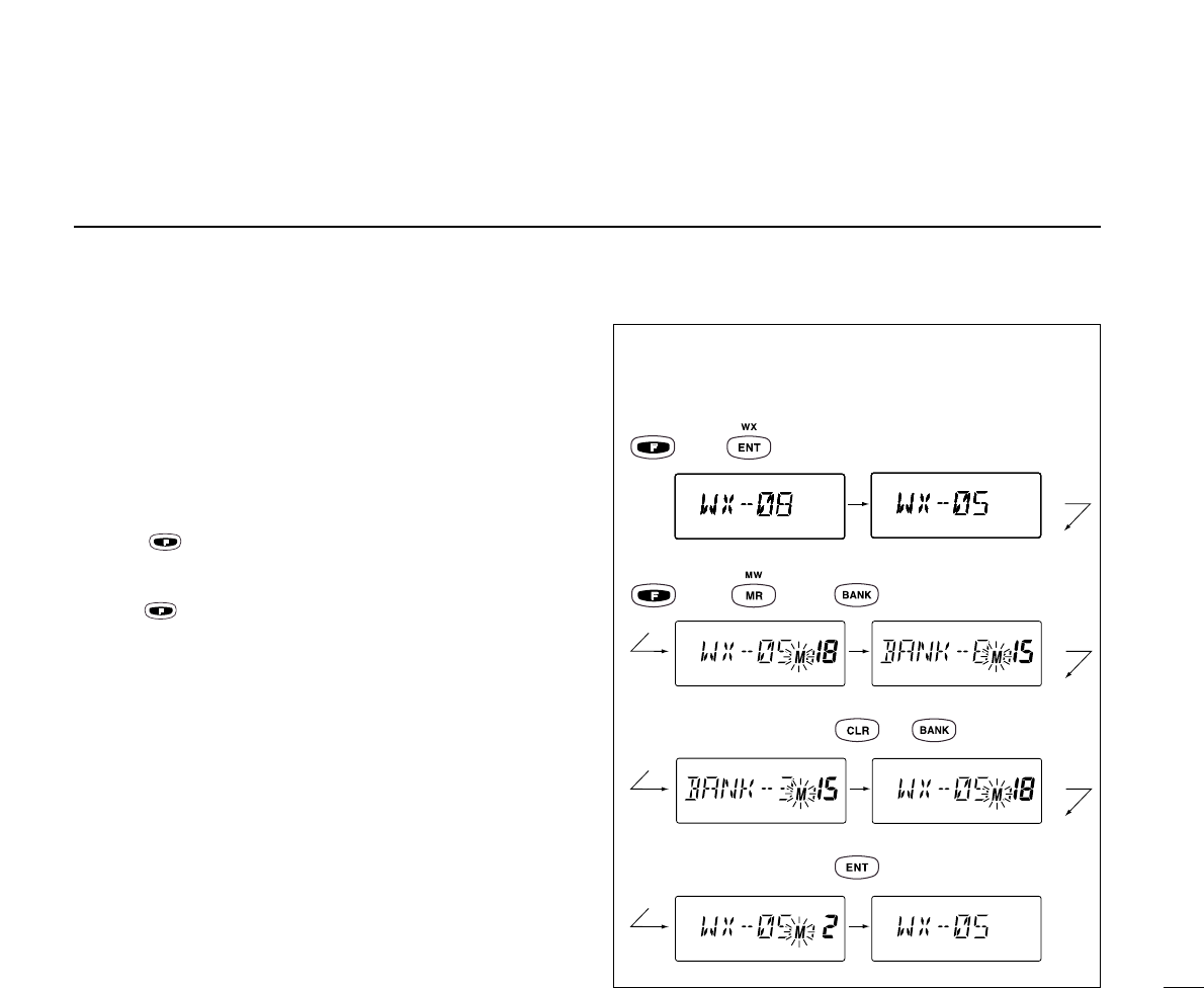
*Weather channel: U.S.A. version only.
then [0], [5] or [5] [ENT]
then
[3]
[0], [2] or [2] then [ENT]
or
•EXAMPLE: Programming WX-05* into memory BANK 3/
memory channel 2.

14
4MEMORY OPERATION
■Memory names
ïProgramming memory names
The memory channel can display a 6-character comment as
well as a frequency.
qRotate the [DIAL] to select the desired frequency in VFO
mode.
wPush ,then push [MR].
eRotate the [DIAL] to select the desired memory channel to
be programmed.
•Push [BANK] to select the BANK number if desired. Push [CLR]
to exit the BANK selection mode.
rPush [MR] to enter the memory name programming mode.
•“-- -- -- -- -- -- ”appears on the display.
tPush the appropriate digit key several times to select the
desired character as listed at right.
•To erase a character, overwrite with a space (displayed as _).
•To move the cursor forwards or backwards, use [DIAL].
yPush [ENT] to program the name.
•Flashing stops.
•When no name is programmed, the display shows the operating
frequency.
•To clear the entered comment, push [CLR] before pushing [ENT].
key Character
1 1, Q, Z
4 4, G, H, I
7 7, P, R, S
ENT Program
key Character
2 2, A, B, C
5 5, J, K, L
8 8, T, U, V
0 0, space, -
key Character
3 3, D, E, F
6 6, M, N, O
9 9, W, X, Y
ïClearing memory contents
Unwanted memory channels can be cleared. Programming
over a memory channel also clears the previously pro-
grammed contents. Memory channel 0 cannot be cleared.
qSelect the memory channel to be cleared.
wPush , then push and hold [CLR] for 1 sec.
•“-- -- -- -- -- --”appears momentarily, then the next selec-
table channel appears.
15
4
MEMORY OPERATION
[CLR], [1], [2], [5], [ENT] [F], [MR(MW)] [1], [5]
(*see NOTE)
[MR] [2], [2], [4], [4], [4], [4] [7], [7], [7]
[0], [0], [0],[2],[3] [ENT]
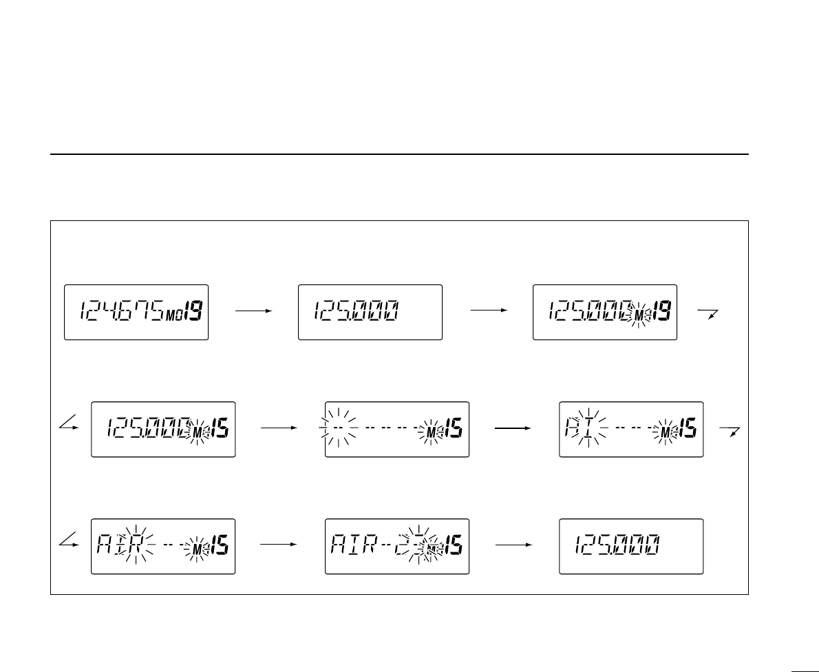
•EXAMPLE: Programming 125.000 MHz into memory BANK 0/ memory channel 15
with “AIR-23”as a comment.
*NOTE: Push [BANK], then rotate the [DIAL] to select the
BANK number, if desired. Push [CLR] to continue memory
name programming.

SCAN OPERATION
5
16
■Scan types
The U.S.A. version has 3 scan types to suit your needs. The
non-U.S.A. versions have 2 scan types.
■COM band scan
qPush [CLR] to select VFO mode.
wSet squelch to the point where noise is just muted.
ePush , then push [SQL (SCAN)] to start the scan.
• When a signal is received, the scan pauses until it disap-
pears.
•To change the scanning direction, rotate the [DIAL].
rTo stop the scan, push [CLR].
■Memory scan
qPush [MR] to select memory mode.
wSet squelch to the point where noise is just muted.
ePush , then push [SQL (SCAN)] to start the scan.
• When a signal is received, the scan pauses until it disap-
pears.
•To change the scanning direction, rotate the [DIAL].
rTo stop the scan, push [CLR].
WEATHER CHANNEL SCAN
Repeatedly scans all “TAG”weather channels. Weather
channels are available for the U.S.A. version only.
MEMORY SCAN
Repeatedly scans all
“TAG”memory channels.
Used for checking often-
used channels and by-
passing usually busy
channels such as control-
tower frequencies..
COM BAND SCAN
Repeatedly scans all fre-
quencies over the entire
COM band.
Scan
Jump
108.00
MHz 118.00
MHz 136.975
MHz
non-TAG
channel
non-TAG channel
Mch 1 Mch 7
Mch 2 Mch 4 Mch 6
Mch 8
Mch 19 Mch 10
5
SCAN OPERATION
17
■Weather channel scan
(U.S.A. version only)
qPush , then push [ENT (WX)] to select a weather
channel.
wSet squelch to the point where noise is just muted.
ePush , then push [SQL (SCAN)] to start the scan.
• When a signal is received, the scan pauses until it disap-
pears.
•To change the scanning direction, rotate the [DIAL].
rTo stop the scan, push [CLR].
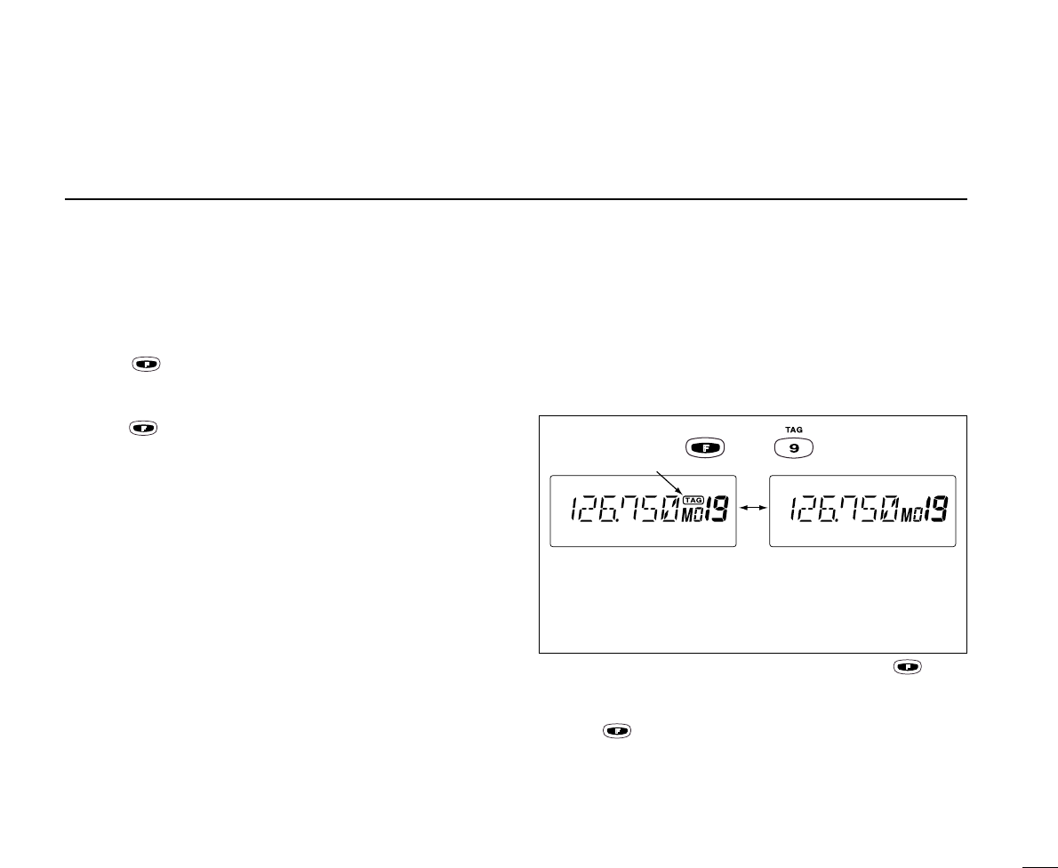
■“TAG” channels
Memory and weather* channels can be specified to be
skipped for the memory and weather* channel scans respec-
tively. The “TAG”channel function is only available during scan
operation.
qPush [MR] to select memory mode; or, push , then
push [ENT (WX)] to select a weather channel*.
wSelect the desired channel to be a “TAG”channel.
ePush , then push [9 (TAG)].
•“TAG”appears.
•Non-“TAG”channels are skipped during scan.
rTo cancel the “TAG”setting, repeat above steps.
*Weather channel: U.S.A. version only.
Memory channel 19 is
scanned during memory
scan.
Memory channel 19 is
skipped during scan.
Shows the
“TAG” channel. then
18
6VOR NAVIGATION (IC-A23 ONLY)
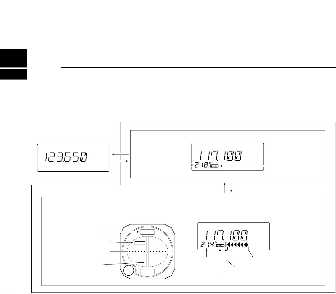
■VOR indicators
214
34
FROM
COM BAND
(118.00–136.975 MHz)
NAV BAND (108.00–117.975 MHz)
DVOR MODE
Function display of the IC-A23General VOR equipment
To-from flag
indicator
CDI MODE
Course indicator
Course
indicator Course deviation needles
Overflow indicator
Push [F] then [r CDI].Push [F] then [q DVOR].
To-from flag indicator
Course indicator
Course deviation
needle
To-from flag indicator
Two-degree deviation
marks
19
6
VOR NAVIGATION
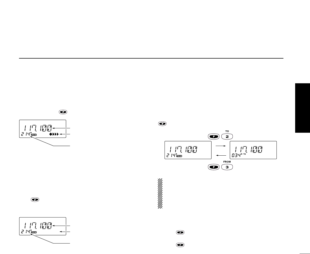
■VOR functions
◊To select CDI mode
To show the deviation between your flying course and the de-
sired course, push , then [4 (CDI)].
◊To select DVOR mode
When entering the NAV band, 108.000–117.975 MHz, the
IC-A23 selects DVOR mode automatically.
To show your aircraft’s direction to (or from) the VOR station,
push , then [1 (DVOR)].
◊‘TO’or ‘FROM’flag selection
The to-from flag indicators indicate whether the VOR naviga-
tion information is based on a course leading to the VOR sta-
tion or leading away from the VOR station.
To change the flag from ‘TO’to ‘FROM’or vice versa, push
, then [3 (FROM)] or [2 (TO)], respectively.
•When using the ‘TO’flag and passing through the VOR
station, the ‘TO’flag changes to the ‘FROM’flag automat-
ically.
•When turning power ON, the ‘FROM’flag is selected au-
tomatically.
◊Selecting the next VOR station when using
CDI mode (when using the course deviation needle)
qPush , then [1 (DVOR)].
wSet the next VOR station’s frequency.
ePush , then [4 (CDI)].
•Select ‘TO’or ‘FROM’flag, if desired.
Operating frequency can be changed.
Co rse indicator shows yo r direction
Course deviation needle does not
appear.
Operating frequency cannot be changed.
Course indicator is fixed, but it can be
changed with the tuning dial or keypad.
Each course deviation arrow indicates
a two-degree deviation.
VOR NAVIGATION
20
6VOR NAVIGATION
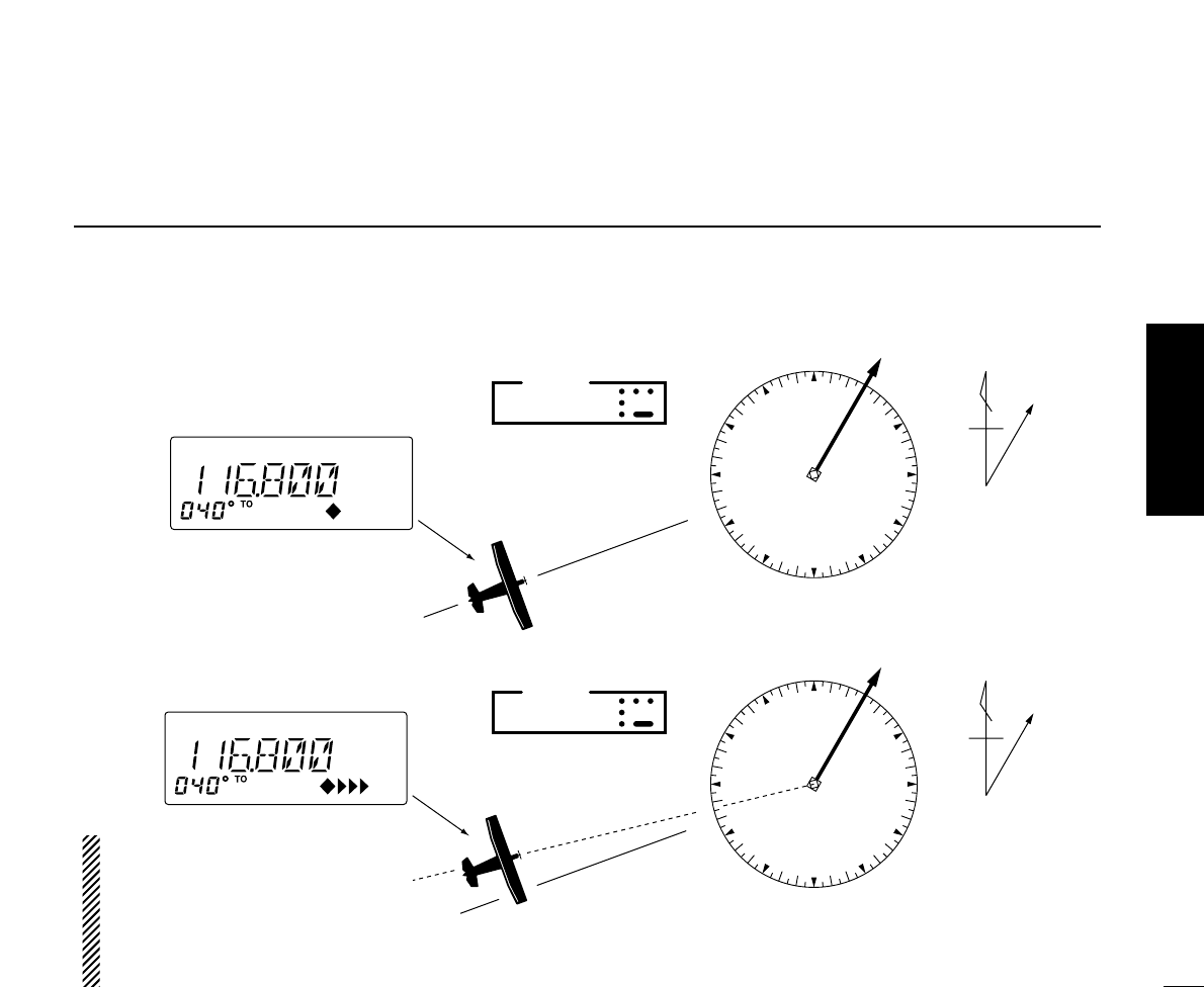
■Flying to a VOR station
The IC-A23 shows the deviation from a VOR station.
qSelect a VOR station on your aeronautical chart and set
the frequency of the station.
•The course indicator indicates where you are located on a radial
from the VOR station.
•The course indicator shows ‘- - -’when either aircraft is too far
away from the VOR station or the frequency is not set correctly at
the VOR station.
wSelect the ‘TO’flag when flying to the VOR station, or se-
lect the ‘FROM’flag when flying away from the VOR sta-
tion.
•To select ‘TO,’push ,then [2 (TO)].
•To select ‘FROM,’push ,then [3 (FROM)].
ePush , then [4 (CDI)] to select CDI (Course Deviation
Indicator) mode.
•The course indicator shows ‘OFF’when the desired VOR signal
cannot be received.
When CDI mode is selected, the operating frequency can-
not be changed. To set the operating frequency, select
DVOR mode in advance.
rThe course deviation needle appears when your aircraft is
off course from the VOR station.
•‘Ω’or ‘≈’appears to indicate your aircraft is off course to the right
or left, respectively. Correct your course until ‘Ω’or ‘≈’disappears.
Each arrow represents a two-degree deviation.
tTo exit CDI mode, push , then [1 (DVOR)].
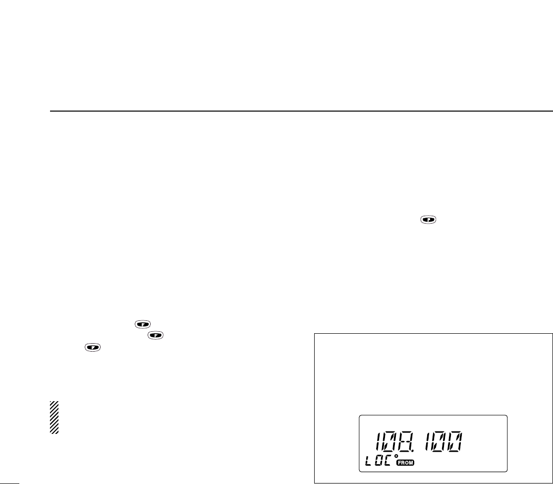
VOR INDICATOR NOTE
‘LOC’appears on the function display as shown below
when a localizer signal is received.
However, the function display does not indicate additional
information about the localizer signal.
21
6
VOR NAVIGATION
VOR
station
0°
10°
20°
30°
40°
50°
60°
70°
80°
90°
100°
110°
120°
130°
140°
150°
160°
170°
180°
190°
200°
210°
220°
230°
240°
250°
260°
270°
280°
290°
300°310°320°330°340°350°
NMagnetic
north
Desired course
Aircraft heading 40°
123.65
VORTAC
SEATTLE
116.8 Ch 115 SEA
THE AIRCRAFT IS ON COURSE
VOR
station
0°
10°
20°
30°
40°
50°
60°
70°
80°
90°
100°
110°
120°
130°
140°
150°
160°
170°
180°
190°
200°
210°
220°
230°
240°
250°
260°
270°
280°
290°
300°310°320°330°340°350°
NMagnetic
north
Aircraft should be
heading 40°
Aircraft heading 46°
(6° off course)
Flown course
123.65
VORTAC
SEATTLE
116.8 Ch 115 SEA
THE AIRCRAFT IS OFF COURSE
The course deviation indicator ap-
pears when the aircraft is off
course. In this example, the aircraft
is 6 degrees off course to the left.
The pilot must turn more than 6
degrees right to get back on
course.
VOR NAVIGATION
22
6VOR NAVIGATION
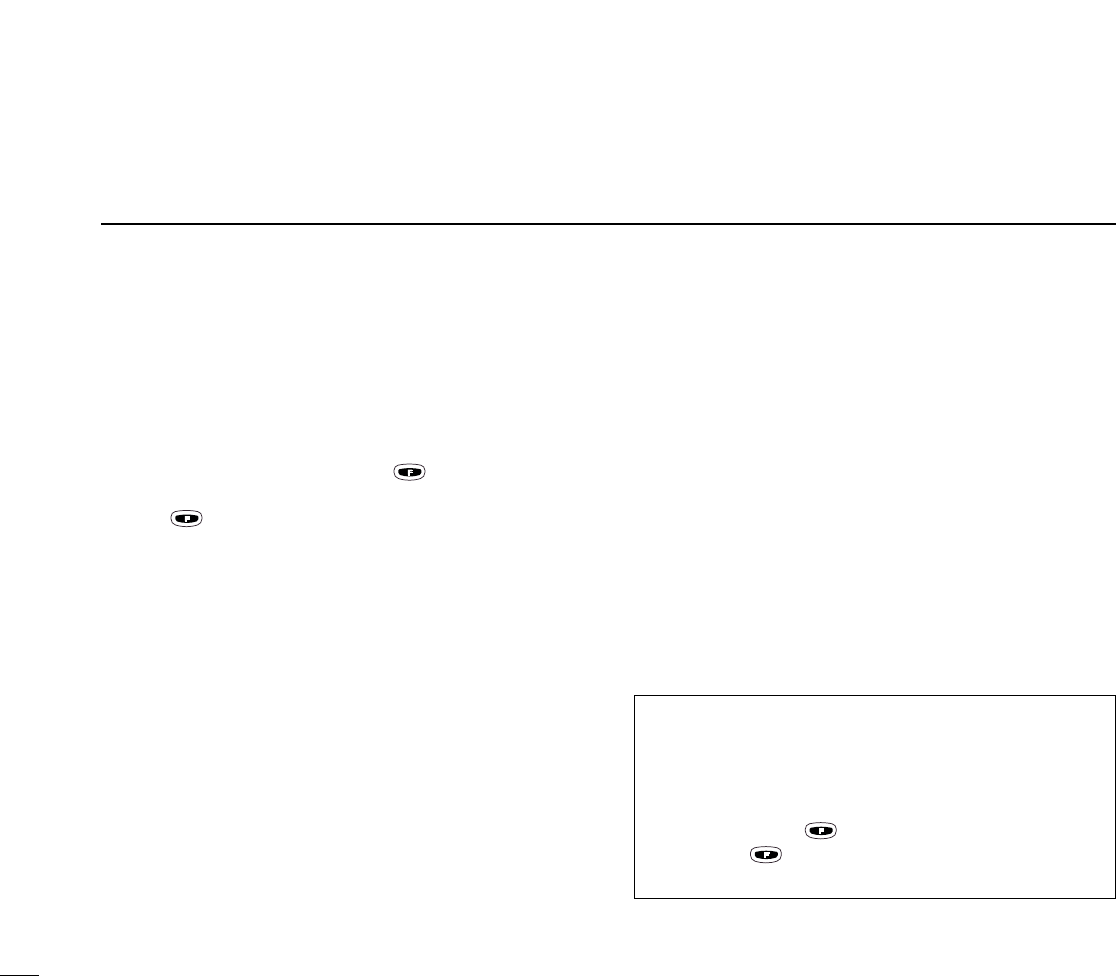
■Entering a desired course
The IC-A23 shows not only the deviation from the VOR sta-
tion but the deviation from the desired course.
qSet the frequency for the desired VOR station.
•To change the to-from flag, push ,then [2 (TO)] or [3
(FROM)].
wPush , then [4 (CDI)] to select CDI mode.
eSet the desired course to the VOR station using the tuning
dial or keypad.
•‘Ω’or ‘≈’appears on the function display when your aircraft is off
the desired course.
•When your heading is correct, the ABSS function may be useful
instead of course input.
rThe course deviation needle points to the right when your
aircraft is off course to the left.
•To get back on course, fly right more than the number of degrees
indicated by the CDI arrows.
•If the overflow indicator appears on the right side, select a head-
ing plus 30 degrees to the desired course; if the overflow indica-
tor appears on the left side, select a heading minus 30 degrees.
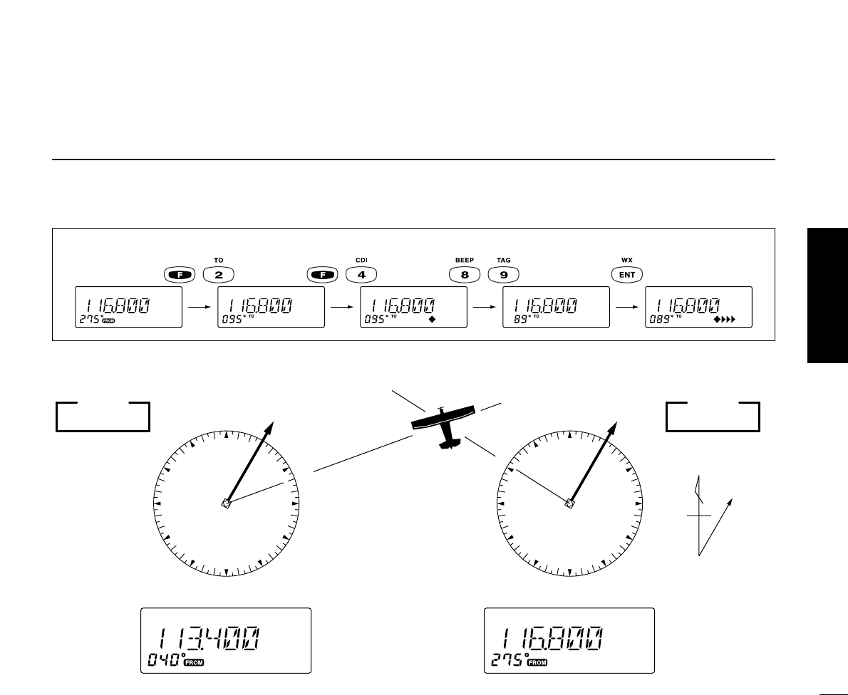
■Crosschecking position
qSelect 2 VOR stations on your aeronautical chart.
wSet the frequency of one of the VOR station in DVOR
mode.
•The course indicator shows course deviation from the VOR ra-
dial. Note the radial you are on.
eSet the frequency of the other VOR station in DVOR mode.
•Note the radial from the station you are on.
rExtend the radials from each VOR station on the chart.
Your aircraft is located at the point where the lines inter-
sect.
ABSS FUNCTION
In CDI mode, the Auto Bearing Set System (ABSS) adds
or subtracts the number of degrees indicated by the CDI
arrows from the Omni Bearing Selector (OBS).
To use ABSS, push , then [2 (TO)] while using the ‘TO
flag; or, push , then [3 (FROM)] while using the ‘FROM’
flag.
23
6
VOR NAVIGATION
EXAMPLE: Entering the desired course bearing 89°to a VOR station.
VOR
station
0°
10°
20°
30°
40°
50°
60°
70°
80°
90°
100°
110°
120°
130°
140°
150°
160°
170°
180°
190°
200°
210°
220°
230°
240°
250°
260°
270°
280°
290°
300°310°320°330°340°350°
NMagnetic
north
VOR
station
0°
10°
20°
30°
40°
50°
60°
70°
80°
90°
100°
110°
120°
130°
140°
150°
160°
170°
180°
190°
200°
210°
220°
230°
240°
250°
260°
270°
280°
290°
300°310°320°330°340°350°
113.4 Ch 81 OLM
VORTAC
OLYMPIA
116.8 Ch 115 SEA
123.65
VORTAC
SEATTLE
CROSSCHECKING POSITION
VOR NAVIGATION
24
6VOR NAVIGATION
■Duplex operation
(U.S.A. version only)
The duplex function allows you to call a flight service station
while receiving a VOR station. The duplex function requires
frequency programming for the flight service station in ad-
vance.
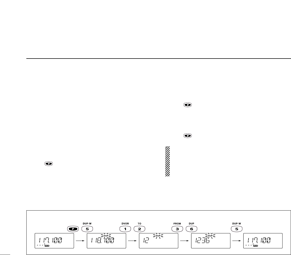
◊Programming a duplex frequency
qPush [CLR] to select frequency mode.
wSet a NAV band frequency using the tuning dial or keypad.
•NAV band frequency range: 108.00–117.975 MHz
ePush , then [5 (DUP-W)].
•“DUP”flashes and transmit frequency appears.
rSet the frequency of the flight service station using the tun-
ing dial or keypad. When using the tuning dial, push [ENT]
after setting a frequency.
•The displayed frequency returns to the NAV band frequency.
◊Operating the duplex function
qSet the desired frequency in NAV band.
•NAV band frequency range: 108.00–117.975 MHz
wPush , then [6 (DUP)] to turn the duplex function ON.
•“DUP”appears on the function display.
ePush and hold [PTT] to transmit at the pre-programmed
transmit frequency.
rRelease [PTT] to return to receive.
tPush , then [6 (DUP)] to cancel the function.
A duplex frequency can be programmed into each mem-
ory channel independently. Set a duplex frequency before
programming the memory channel, if desired. The duplex
ON/OFF setting can also be programmed into a memory
channel.
EXAMPLE: Programming 123.65 MHz as the transmit frequency in the duplex function.

25
7
BATTERY PACKS
■Charging
precautions
NEVER connect two or more chargers
at the same time.
Charging may not occur under temper-
atures of 10°C (+50°F) or over temper-
atures of 40°C (+104°F).
When using BC-119: If the charge
indicator flashes orange, vehicle bat-
tery voltage is low and charging is
not possible. Check the vehicle bat-
tery voltage in this case. If the charge
indicator flashes red, there may be a
problem with the battery pack (or
charger). Re-insert the battery pack
or contact your dealer.
■Battery pack
charging
The BP-200L
BATTERY PACK
includes
rechargeable Ni-MH batteries and can
be charged approx. 300 times. Charge
the battery pack before first operating
the transceiver or when the battery
pack becomes exhausted.
If you want to be able to charge the bat-
tery pack more than 300 times, the fol-
lowing points should be observed:
1.Avoid overcharging. The charging pe-
riod should be less than 48 hours.
2.Use the battery until it becomes al-
most completely exhausted under
normal conditions. We recommend
battery charging just after transmitting
becomes impossible.
D
Rapid charging with the BC-119
The optional BC-119 provides rapid
charging of battery packs.
One AD-87 and an AC adapter (may be
supplied with the BC-119 depending on
version) are additionally required.
qFix the optional AD-88 TERMINAL PC
BOARD FOR CHARGER into the BC-
119 with the 4 supplied screws.
wInsert the optional AD-87A* CHARGE
ADAPTER into the charging slot of
the BC-119.
eInsert the optional AD-87B* CHARGE
ADAPTER into the AD-87A* CHARGE
ADAPTER.
rInsert the battery pack, either by it-
self or attached to the transceiver,
into the whole assembly for charg-
ing. (p. 26)
*AD-87A and AD-87B supplied together named
as AD-87.
•Charging period: 2 hours
26
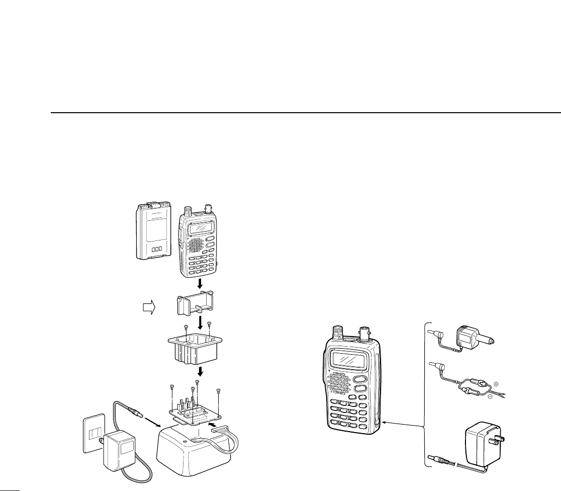
7BATTERY PACKS
DRapid charging with the 119 DRegular charging
qAttach the battery pack to the transceiver.
wBe sure to turn the transceiver power OFF.
eConnect the Wall charger (BC-110A) or optional cable
(CP-12L or OPC-254L) as shown below.
•Charging period: 10 hours
IC-A23/A5 with
attached
battery case
Wall charger
CP-12L
(optional)
OPC-254L
(optional)
To a 12 to
14 V DC
power source
To
[CHARGE]
white
black
*AD-87B
(supplied with AD-87A)
AD-88
(optional)
Check orientation
for correct charging
AD-87A
(optional)
BC-119
(optional)
*

BATTERY PACKS 7
27
■About the battery pack
DOperating period
The operating period of the transceiver is 6 hours.
•Operating periods are calibrated for the following conditions:
at 25°C (77°F), Tx (high power) : Rx : standby = 5 : 5 : 90
DBattery pack life
If your battery pack seems to have no capacity even after
being fully charged, completely discharge it by leaving the
power ON overnight. Then, fully charge the battery pack
again.
If the battery pack still does not retain a charge (or very little),
a new battery pack must be purchased.
■Battery pack CAUTION
●NEVER short the terminals of the battery pack. Also, cur-
rent may flow into nearby metal objects, such as a neck-
lace, etc. Therefore, be careful when carrying with, or
placing near metal objects, carrying in handbags, etc.
●Keep battery contacts clean. It’s a good idea to clean bat-
tery terminals once a week.

28
8CLONING
Cloning allows you to quickly and easily transfer the
programmed contents from one transceiver to another
transceiver, or, data from PC to a transceiver using the
optional CS-A23 cloning software.
DTransceiver to transceiver cloning
qConnect the OPC-474 CLONING CABLE with adapter plugs to
the [SP/MIC] jack of the master and slave transceivers.
•The master transceiver is used to send data to the slave trans-
ceiver.
wWhile push and holding [Y] + [Z],push [PWR] ON to enter
cloning mode (for both the master transceiver and slave
transceiver both.).
•“CLONE”appears and the transceivers enter the clone
standby condition.
ePush [PTT] on the master
transceiver.
•“CL-OUT”appears in the
master transceiver’s display.
•“CL-IN”appears automati-
cally in the slave trans-
ceiver’s display.
rWhen cloning is finished,
turn power OFF, then ON
again to exit cloning mode.
DCloning using PC
Data can be cloned to and from a PC (IBM compatible) using
the optional CS-A23 CLONING SOFTWARE and the optional OPC-
478 CLONING CABLE. Consult the CS-A23 CLONING SOFTWARE HELP
message for details.
DCloning error
NOTE: DO NOT push [PTT] on the slave transceiver dur-
ing cloning. This will cause a cloning error.
When the display at right ap-
pears, a cloning error has oc-
curred.
In this case, both transceivers automatically return to the
clone standby condition and cloning must be repeated.

9
TROUBLESHOOTING
29
If your transceiver seems to be malfunctioning, please check
the following points before sending it to a service center.
POSSIBLE CAUSE SOLUTION REF.
No power comes on. •The battery is exhausted.
•Bad connection for the battery pack.
•Recharge the battery pack.
•Check the connection to the
transceiver.
pgs. 23,
25
No sound comes from the
speaker.
•Squelch level is too deep.
•Volume level is too low.
•Set squelch to the threshold point.
•Set [VOL] to a suitable level.
pgs. 9, 10
Transmitting impossible. •Some channels are receive only.
•The battery is exhausted.
•Change channels.
•Recharge the battery pack.
p. 8
p. 23
The displayed channel
cannot be selected.
•Lock function is activated. •Push [F], then push [7 (KEY LOCK)]. p. 10
Scan does not start. •All memory channels are not
programmed as “TAG” channels.
•Set the “TAG” settings of desired
channels.
p. 16
No beep sounds. •Beep tones turned OFF. •Push [F], then push [8 (BEEP)] to
adjust the beep tone level. p. 9
PROBLEM

10 SPECIFICATIONS
DGeneral
•Frequency coverage : TX 118.000 to 136.975 MHz
RX 108.000 to 136.975 MHz
WX 161.650 to 163.275 MHz
•Mode : 6K00A3E
16K0G3E (161.65. to 163.275 MHz)
•Number of memory channels : 200 (10 BANK x 20 CH)
•Acceptable power supply : 9.6 V DC nominal
(negative ground) (authorized battery packs)
•Usable temp. range : –10˚C to +60˚C
•Frequency stability : ±17 ppm (–0˚C to +60˚C)
•Current drain :
Tx 1.8 A (CW) max.
1.1 A (CW) typical
Rx 70 mA typical (at stand by)
500 mA max. (at AF max.)
•Antenna impedance : 50 Ω(nominal)
•Dimensions : 58(W)✕107(H)✕28.5(D) mm
(projections not incl.)
•Weight (with BP-200L) : 340 g
DTransmitter
•Output power : 5 W (PEP) typical
1.5 W (CW) typical
•Modulation : Low level modulation
•Modulation limiting : 70 to 100 %
•Audio harmonic distortion : Less than 10 %
(at 60 % modulation)
•Hum and noise ratio : More than 35 dB
•Spurious emissions : More than 60 dB
•Microphone impedance : 150 Ω
DReceiver
•Receive system : Double conversion
superheterodyne
•Intermediate frequencies : 1st 30.05 MHz
2nd 450 kHz
•Sensitivity (AM 6dB S/N) : Less than 0dBµ
(FM 12dB SINAD): Less than 0dBµ
•Squelch sensitivity (AM) : Less than –3dBµ
(FM ) : Less than –13dBµ
•Selectivity : 7.5 kHz (at 6 dB) or more
25 kHz (at 60 dB) or less
•Spurious response : More than 60 dB
•Audio output power : 400 mW (at 10% distortion
(at 9.6 V DC) with an 8 Ωload)
•Noise and hum : More than 25 dB
•External SP connector : 3-conductor 3.5 (d) mm /8 Ω
All stated specifications are subject to change without
notice or obligation.
30

11
OPTIONS
31
DBattery packs
1Operating periods are calibrated for the following conditions:
at 25°C (77°F), Tx (high power) : Rx : standby = 5 : 5 : 90
DOther options
BC-110A WALL CHARGER (same as supplied. Depends on version)
Used for regular charging of the connected battery pack.
BC-119 DESKTOP CHARGER + AD-88 CHARGER ADAPTOR
For rapid charging of battery packs. An AC adapter is sup-
plied with the charger. Some BC-119 versions require the AD-
87 additionally. Charging time: 1.5 to 2 hrs.
OPC-254L
DC POWER CABLE
CP-12L
CIGARETTE LIGHTER CABLE WITH NOISE FILTER
Allows you to charge a battery pack connected to the trans-
ceiver via a DC power source (12–14 V DC) For charging
ONLY—the transceiver cannot be simultaneously operated.
SP-13
EARPHONE
Provides clear audio in noisy environments.
OPC-967 HEADSET ADAPTER
When using an optional headset, such as those from the
David Clark Co. via the adapter, the transceiver outputs your
transmitted voice to the headset for monitoring. (p. 9)
CS-A23
CLONING SOFTWARE
Provides quick and easy programming of items, including pri-
vate channels, scan settings, etc., via an IBM®compatible PC
to transceiver.
OPC-474
CLONING CABLE
Cloning cable for transceiver to transceiver cloning.
OPC-478
CLONING CABLE
Cloning cable for PC to transceiver cloning.
IBM®is a registered trademark of International Business Machines.
yrettaB kcap egatloV yticapaC
doirepgnigrahC gnitarepO *doirep
1
llaW regrahc
ro911-CB 121-CB 88-DAhtiw
BP-200L V6.9 hAm007 srh01srh5.1 srh6
11
32
OPTIONS
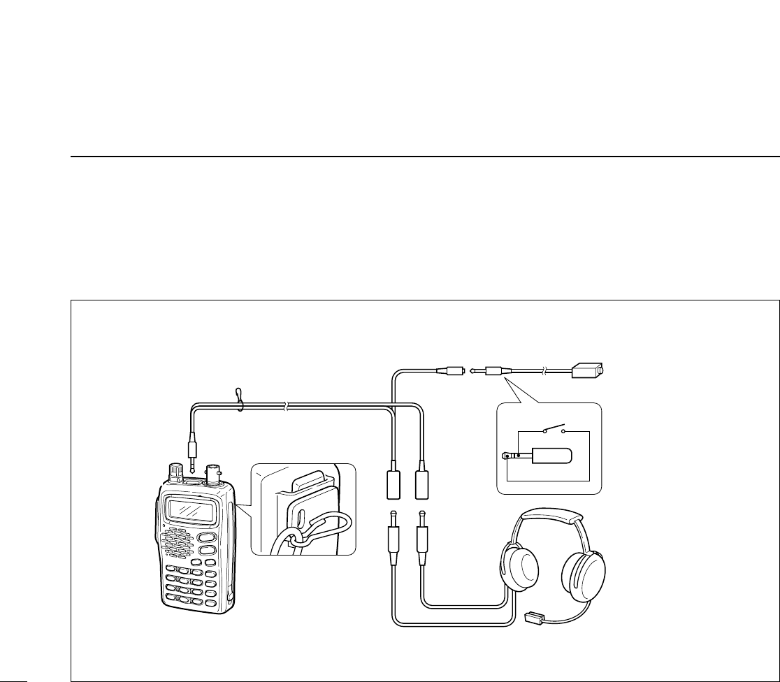
DOPC-967 (HEADSET ADAPTER) connection
When using an optional headset, such as those from the
David Clark Co. via the adapter, the transceiver outputs your
transmitted voice to the headset for monitoring. (p. 9)
PTT switch
Use a PTT switch
with a 3.5 mm diame-
ter plug, if required.
HEADSET
(Must be purchased
separately.)
Clip the cable to the
handstrap loop on
the beltclip for sup-
port.
OPC-967
IC-A23
IC-A5
PTT

33

Count on us!
6-9-16 Kamihigashi, Hirano-ku, Osaka 547-0002 Japan
A-5665H-1EX
Printed in Japan
© 2000 Icom Inc.