ICOM orporated IC-F21 UHF-FM Hand Held Transceiver User Manual Icom UHF Transceiver Instruction Manual
ICOM Incorporated UHF-FM Hand Held Transceiver Icom UHF Transceiver Instruction Manual
UserManual.wiki
>
ICOM orporated
>
IC F21 User Manual
Icom UHF Transceiver Instruction Manual
Navigation menu
Upload a User Manual
Namespaces
Wiki Guide
HTML
PDF
Info
Views
User Manual
Discussion / Help
Navigation
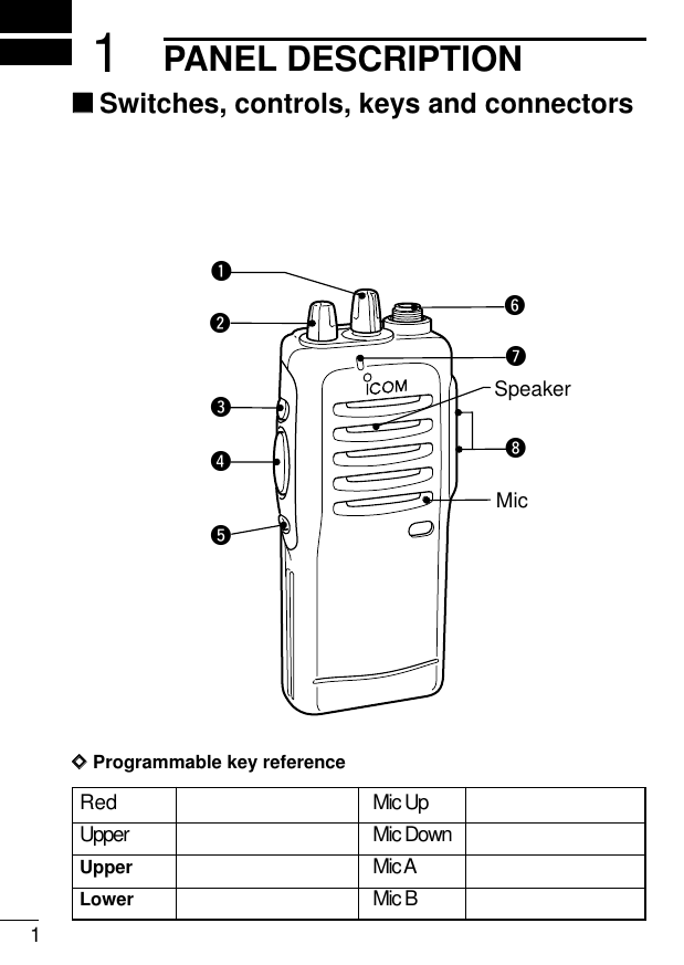
![21PANEL DESCRIPTIONqCHANNEL SELECTOR KNOB [CH]Turns to select the programmed operating channel.wVOLUME CONTROL [OFF/VOL]Turns power ON and adjusts the audio level.eDEALER-PROGRAMMABLE KEY [Upper]rPTT SWITCH [PTT]Push and hold to transmit; release to receive.tDEALER-PROGRAMMABLE KEY [Lower]yANTENNA CONNECTORConnects the supplied antenna.uTX/RX INDICATOR LEDUsed to enter DTMF codes, the operating channel, etc.i[SP]/[MIC] JACKConnect optional speaker-microphone.NOTE: Above functions depend on pre-setting.](https://usermanual.wiki/ICOM-orporated/IC-F21/User-Guide-137722-Page-7.png)
![114PROGRAMMABLE FUNCTIONS‘‘GeneralIn the following explanations, programmable function names arebracketed, the specific switch used to activate the function dependson programming.DDKEYPAD LOCK FUNCTIONThis function locks access to all programmable switches (exceptthe switch assigned for the lock function).:Push and hold the [LOCK] switch for 1 sec. to toggle the lock func-tion ON and OFF.• This function may be inhibited on some channels.DDPRIORITY CHANNELThis function is used to select a pre-programmed channel at thepush of a switch.Push the [PRIORITY] switch to select the priority channel.• “PRIO” appears briefly, then the priority channel is automaticallyselected.DDSCAN FUNCTIONThe scan function allows you to search a pre-programmed groupof channels for signals.Push the [SCAN] switch to start/stop scan.• Scan pauses on a channel when receiving a signal.• Depending on programming, a message may appear while scan-ning.• “Lockout SCAN” (pre-programmed list SCAN) or “Priority SCAN”can be pre-programmed.• When the “Power-save function” is activated, the transceiverchecks all pre-programmed channels then returns to the “Power-](https://usermanual.wiki/ICOM-orporated/IC-F21/User-Guide-137722-Page-15.png)
![124PROGRAMMABLE FUNCTIONSsave function” again.DDHIGH/LOW POWER OUTPUTThis function selects high or low power for a channel.Push the [HIGH/LOW] switch to toggle between high and lowpower.](https://usermanual.wiki/ICOM-orporated/IC-F21/User-Guide-137722-Page-16.png)
![134PROGRAMMABLE FUNCTIONSDDMONITOR AUDIBLE FUNCTIONThe monitor function allows you to open the transceiver’s squelchmanually to check whether a channel is busy or not. The trans-ceiver has 2 conditions for receive standby:Audible condition:This condition mutes audio ONLY whenno carrier is present. You can receive (ormonitor) any signals on a channel.• Push and hold the [MONI/AUDI], switchto select the audible condition.Any audio mute functions are cancelledwhile pushing the [MONI/AUDI] switch.Inaudible condition:This condition mutes ALL signals exceptthose directed to you. Therefore youshould check a channel’s condition (busyor not) with the monitor function beforetransmitting.• Push the [MONI/AUDI] switch momen-tarily to select the inaudible condition.DDTALK AROUNDThe talk around function changes duplex channels to simplex chan-nels.• Duplex allows you to contact your base station, repeaters, etc.• Simplex allows you to contact other portable transceivers directly(portable-to-portable contact).Push the [TALK AROUND] switch one or more times to toggle thefunction ON and OFF.All signals arereceived2345678901P0P1P2P3Only signals containing the propertone arereceived2345678901P0P1P2P3](https://usermanual.wiki/ICOM-orporated/IC-F21/User-Guide-137722-Page-17.png)
![144PROGRAMMABLE FUNCTIONSDDDTMF TRANSMISSIONThis function allows you to send a pre-programmed DTMF code tocontrol a repeater, open another transceiver’s squelch, etc.Manual transmission:Push desired digit keys in sequence while pushing [PTT].• Pushing [PTT] may not be necessary depending on programming.Automatic pre-programmed transmission:Push the [DTMF Autodial] switch to send a DTMF code.DDEMERGENCY FUNCTIONThe emergency function allows you to send your ID quickly andeasily to your Base Station, etc. in case of emergency.Push and hold the [EMERGENCY SINGLE/REPEAT] switch for 1sec. to activate the emergency function.• The transceiver selects a pre-programmed channel, then sendsan emergency signal to your Base Station.• The pre-programmed channel remains selected until a control sig-nal is received from the Base Station, or power is turned OFF.• The emergency call is repeatedly transmitted at pre-programmedintervals.DDMR-CH1–4Tush to ..](https://usermanual.wiki/ICOM-orporated/IC-F21/User-Guide-137722-Page-18.png)
![165CONVENTIONAL OPERATION‘‘Receiving and transmittingNOTE: Transmitting without an antenna may damage the trans-ceiver. See p.1 for antenna attachment.Turn power ON as described on p. 1.Receiving:qSelect a desired channel.wListen for a transmission and adjust [VOL] to a comfortable lis-tening level.• When no transmission is heard, push and hold monitor whileadjusting [VOL] (your transceiver may not be programmed withthe monitor function).The transceiver is now set to receive desired calls on the selectedchannel.Transmitting:Wait for the channel to become clear to avoid interference.eWhile pushing and holding [PTT], speak into the microphone at anormal voice level.• When a tone signalling system is used, the call procedure de-scribed at right may be necessary.rRelease [PTT] to return to receive.IMPORTANT: To maximize the readability of your transmitted sig-nal, pause a few sec. after pushing [PTT], hold the microphone 10to 15 cm from your mouth and speak at a normal voice level.](https://usermanual.wiki/ICOM-orporated/IC-F21/User-Guide-137722-Page-19.png)
![175CONVENTIONAL OPERATION‘‘Call procedureWhen your system employs tone signalling (excluding CTCSS andDTCS), the call procedure may be necessary prior to voice trans-mission. The tone signalling employed may be a selective callingsystem which allows you to call specific station(s) only and preventunwanted stations from contacting you.qSelect the desired Tx code channel or 5-tone code according toyour System Operator’s instructions.• This may not be necessary depending on programming.• Refer to the next page for selection.wPush the call switch (assigned to one of the dealer programma-ble switches: [Upper] and [Lower]).eAfter transmitting a 5-tone code, the remainder of your commu-nication can be carried out in the normal fashion.2345678901P0P1P2P32345678901P0P1P2P32345678901P0P1P2P32345678901P0P1P2P32345678901P0P1P2P32345678901P0P1P2P32345678901P0P1P2P32345678901P0P1P2P3Non-selective callingSelective calling](https://usermanual.wiki/ICOM-orporated/IC-F21/User-Guide-137722-Page-20.png)
![249CLONING‘‘CloningCloning allows you to quickly and easily transfer the programmedcontents from one transceiver to another transceiver; or data fromPC to a transceiver using the optional CS-F11 CLONING SOFT-WARE.DDTransceiver-to-transceiver cloningqConnect the optional OPC-474 CLONING CABLE with adapterplugs to the [SP] jack of the master and slave transceivers.•The master transceiver is used to send data to the slave trans-ceiver.wWhile pushing [PTT] and [Upper], turn the transceiver’s poweron to enter cloning mode (master transceiver only–power ONonly for slave transceiver).ePush [PTT] on the master transceiver.•When cloning is finished, “Beep” tone emits tow times.NOTE: DO NOT push the [PTT] on the slave transceiver duringcloning. This will cause a cloning error.rWhen cloning is finished, turn power off, then on again to returnto normal operation.DDPC-to-transceiver cloningPlease refer to the HELP file that comes with the CS-F11 CLONINGSOFTWARE.CAUTION: Imprudent cloning operation causes a cloning error.In such a case, memory contents may be lost. Cloning mustthen be repeated.](https://usermanual.wiki/ICOM-orporated/IC-F21/User-Guide-137722-Page-23.png)