ICOM orporated IC-F21 UHF-FM Hand Held Transceiver User Manual Icom UHF Transceiver Instruction Manual
ICOM Incorporated UHF-FM Hand Held Transceiver Icom UHF Transceiver Instruction Manual
Icom UHF Transceiver Instruction Manual
INSTRUCTION MANUAL
UHF TRANSCEIVER
iF21/S
This device complies with Part 15 of the FCC rules. Oper-
ation is subject to the following two conditions: (1) This de-
vice may not cause harmful interference, and (2) this
device must accept any interference received, including in-
terference that may cause undesired operation.
VHF TRANSCEIVER
iF11/S

i
Your Icom radio generates RF electromagnetic
energy during transmit mode. This radio is de-
signed for and classified as “Occupational Use
Only”, meaning it must be used only during the
course of employment by individuals aware of the
hazards, and the ways to minimize such hazards.
This radio is NOT intended for use by the “General Popula-
tion” in an uncontrolled environment.
This radio has been tested and complies with the FCC RF expo-
sure limits for “Occupational Use Only.” In addition, your Icom radio
complies with the following Standards and Guidelines with regard to
RF energy and electromagnetic energy levels and evaluation of
such levels for exposure to humans:
• FCC OET Bulletin 65 Edition 97-01 Supplement C, Evaluating
Compliance with FCC Guidelines for Human Exposure to Radio
Frequency Electromagnetic Fields.
• American National Standards Institute (C95.1 – 1992), IEEE Stan-
dard for Safety Levels with Respect to Human Exposure to Radio
Frequency Electromagnetic Fields, 3 kHz to 300 GHz.
• American National Standards Institute (C95.3 – 1992), IEEE Rec-
ommended Practice for the Measurement of Potentially Hazardous
Electromagnetic Fields – RF and Microwave.
To ensure that your exposure to RF electromag-
netic energy is within the FCC allowable limits for
occupational use, always adhere to the following
guidelines:
•DO NOT operate the radio without a proper antenna attached, as
this may damage the radio and may also cause you to exceed FCC
RF exposure limits. A proper antenna is the antenna supplied with
WARNING
CAUTION
SAFETY TRAINING INFORMATION

ii
this radio by the manufacturer or an antenna specifically authorized
by the manufacturer for use with this radio.
•DO NOT transmit for more than 50% of total radio use time (
“
50%
duty cycle”). Transmitting more than 50% of the time can cause
FCC RF exposure compliance requirements to be exceeded. The
radio is transmitting when the “TX indicator” lights red. You can
cause the radio to transmit by pressing the “PTT” switch.
•ALWAYS use Icom authorized accessories (antennas, batteries,
belt clips, speaker/mics, etc). Use of unauthorized accessories can
cause the FCC RF exposure compliance requirements to be ex-
ceeded.
• ALWAYS keep the antenna at least 2.5 cm (1 inches) away from
the body when transmitting and only use the Icom belt-clips which
listed in p. 26 when attaching the radio to your belt, etc., to ensure
FCC RF exposure compliance requirements are not exceeded. To
provide the recipients of your transmission the best sound quality,
hold the antenna at least 5 cm (2 inches) from mouth, and slightly
off to one side.
The information listed above provides the user with the information
needed to make him or her aware of RF exposure, and what to do to
assure that this radio operates within the FCC RF exposure limits of this
radio.
Electromagnetic Interference/Compatibility
During transmissions, your Icom radio generates RF energy that
can possibly cause interference with other devices or systems. To
avoid such interference, turn off the radio in areas where signs are
posted to do so. DO NOT operate the transmitter in areas that are
sensitive to electromagnetic radiation such as hospitals, aircraft,
and blasting sites.

iii
FOREWORD
Thank you for purchasing the IC-F11/S, F21/S FM transceiver.
READ ALL INSTRUCTIONS carefully and completely before using
the transceiver.
SAVE THIS INSTRUCTION MANUAL–This instruction manual
contains important operating instructions for the transceiver.
IMPORTANT
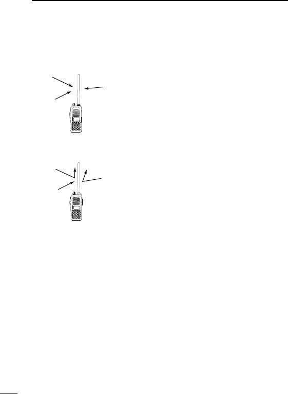
RCAUTION! NEVER hold the transceiver so that the antenna is
very close to, or touching exposed parts of the body, especially the
face or eyes, while transmitting. The transceiver will perform best if
the microphone is 2 to 4 in. (5 to 10 cm) away from the lips and the
transceiver is vertical.
RCAUTION! NEVER operate the transceiver with a headset or
other audio accessories at high volume levels.
RCAUTION! NEVER short the terminals of the battery pack.
DO NOT push the PTT when not actually desiring to transmit.
AVOID using or placing the transceiver in direct sunlight or in areas
with temperatures below +14°F (–10°C) or above +122°F (+50°C).
DO NOT modify the transceiver for any reason.
KEEP the transceiver from the heavy rain, and Never immerse it in
the water. The transceiver construction is water resistant, not
water proof.
The use of non-Icom battery packs/chargers may impair transceiver
performance and invalidate the warranty.
FCC caution: Changes or modifications to this transceiver, not
expressly approved by Icom Inc., could void your authority to op-
erate this transceiver under FCC regulations.

iv
TABLE OF CONTENTS
SAFETY TRAINING INFORMATION . . . . . . . . . . . . . . . . . . . . . . .i-ii
FOREWORD . . . . . . . . . . . . . . . . . . . . . . . . . . . . . . . . . . . . . . . . . .iii
IMPORTANT . . . . . . . . . . . . . . . . . . . . . . . . . . . . . . . . . . . . . . . . . .iii
TABLE OF CONTENTS . . . . . . . . . . . . . . . . . . . . . . . . . . . . . . . . .iv
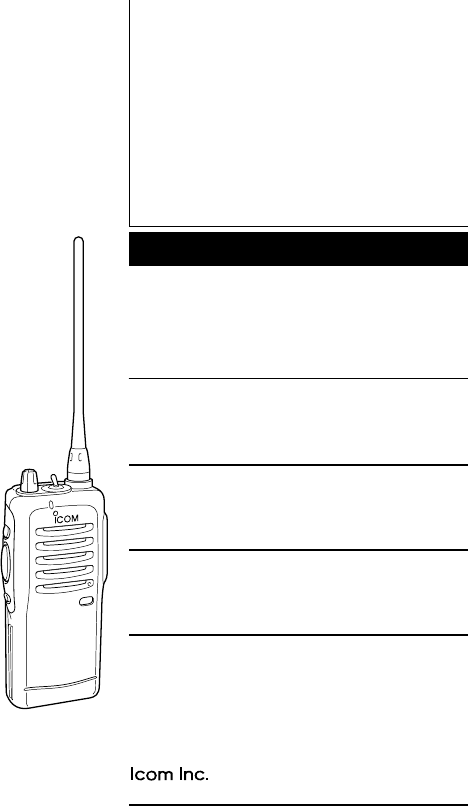
1 PANEL DESCRIPTION . . . . . . . . . . . . . . . . . . . . . . . . . . . . . .1–3
‘Switches, controls, keys and connectors . . . . . . . . . . . . . . .1–2
‘Function display . . . . . . . . . . . . . . . . . . . . . . . . . . . . . . . . . . . .3
2 ACCESSORIES . . . . . . . . . . . . . . . . . . . . . . . . . . . . . . . . . . . . . .4
3 BATTERY PACKS . . . . . . . . . . . . . . . . . . . . . . . . . . . . . . . . .5–10
‘Battery pack replacement . . . . . . . . . . . . . . . . . . . . . . . . . . . .5
‘Battery cautions . . . . . . . . . . . . . . . . . . . . . . . . . . . . . . . . . . . .6
‘Battery charging . . . . . . . . . . . . . . . . . . . . . . . . . . . . . . . . . .7-8
‘ Charging NOTE . . . . . . . . . . . . . . . . . . . . . . . . . . . . . . . . . . .9
‘ Battery case (Option) . . . . . . . . . . . . . . . . . . . . . . . . . . . . . .10
44 PPRROOGGRRAAMMMMAABBLLEE FFUUNNCCTTIIOONNSS .. .. .. .. .. .. .. .. .. .. .. .. .. .. .. .. .. .. .. .. ..11-15
‘Receiving and transmitting . . . . . . . . . . . . . . . . . . . . . . . . . . .11
5 CONVENTIONAL OPERATION . . . . . . . . . . . . . . . . . . . . . .16-18
‘Call procedure . . . . . . . . . . . . . . . . . . . . . . . . . . . . . . . . . . . .17
‘Tx code channel selection . . . . . . . . . . . . . . . . . . . . . . . . . . .18
‘Manual 5-tone codes . . . . . . . . . . . . . . . . . . . . . . . . . . . . . . .18
‘Transmitting notes . . . . . . . . . . . . . . . . . . . . . . . . . . . . . . . . .18
6 SMARTRUNK IITM OPERATION . . . . . . . . . . . . . . . . . . . . . .19-21
‘Basic operation . . . . . . . . . . . . . . . . . . . . . . . . . . . . . . . . . . .19
7 OTHER FUNCTIONS . . . . . . . . . . . . . . . . . . . . . . . . . . . . . . . . .22
‘DTMF pager/Code squelch . . . . . . . . . . . . . . . . . . . . . . . . . .22
8 MAINTENANCE . . . . . . . . . . . . . . . . . . . . . . . . . . . . . . . . . . . . .23
‘ Optional UT-105/UT-108/UT-109 and UT-110 installation . .23
9 CLONING . . . . . . . . . . . . . . . . . . . . . . . . . . . . . . . . . . . . . . .24-25
10 OPTION . . . . . . . . . . . . . . . . . . . . . . . . . . . . . . . . . . . . . . . .25-26
1
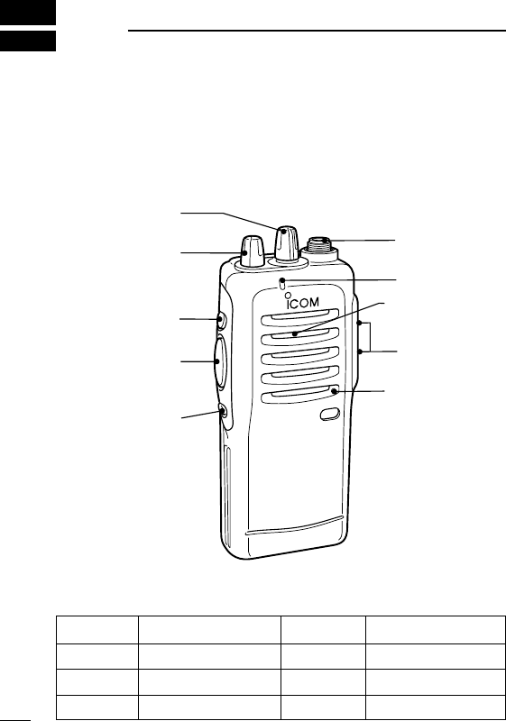
PANEL DESCRIPTION
1
‘‘Switches, controls, keys and connectors
q
y
u
Speaker
Mic
w
e
r
t
i
Red
Upper
Upper
Lower
Mic Up
Mic Down
Mic A
Mic B
DDProgrammable key reference

2
1
PANEL DESCRIPTION
qCHANNEL SELECTOR KNOB [CH]
Turns to select the programmed operating channel.
wVOLUME CONTROL [OFF/VOL]
Turns power ON and adjusts the audio level.
eDEALER-PROGRAMMABLE KEY [Upper]
rPTT SWITCH [PTT]
Push and hold to transmit; release to receive.
tDEALER-PROGRAMMABLE KEY [Lower]
yANTENNA CONNECTOR
Connects the supplied antenna.
uTX/RX INDICATOR LED
Used to enter DTMF codes, the operating channel, etc.
i[SP]/[MIC] JACK
Connect optional speaker-microphone.
NOTE: Above functions depend on pre-setting.
2
ACCESSORIES
4
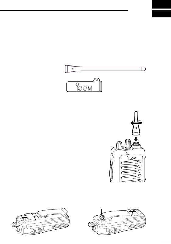
‘‘Accessory attachment
DSupplied accessories
The transceiver comes supplied with the following accessories.
qFlexible antenna
wBelt clip
DAntenna
The antenna screws onto the transceiver as
illustrated right.
DBelt clip
Attach the belt clip to the transceiver as illus-
trated below.
q
w
To attach the belt-clip To release the belt-clip
5
3BATTERY PACKS
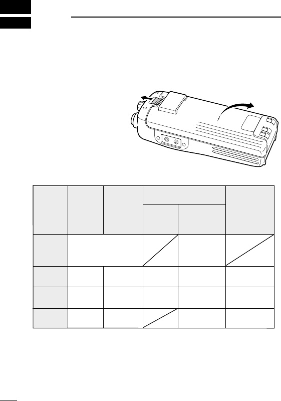
‘‘Battery pack replacement
Before replacing the battery pack, the volume control MUST be ro-
tated fully counterclockwise, until a click is heard, to turn the power
OFF.
•Push the battery re-
lease forward, then pull
the battery pack up-
ward with the trans-
ceiver facing you.
DDBATTERY PACKS
*1Operating periods are calculated under the following conditions;
Tx : Rx : standby =5 : 5 : 90
*1Operating period depends on the alkaline cells used. (BP-208 only)
*2Output power is automatically reduced to 1 W to retains sufficient power
in case of emergency, etc.
yrettaB kcap egatloV yticapaC
doirepgnigrahC gnitarepO *doirep
1
BC-146
ro911-CB 121-CB 49-DAhtiw
BP-208*
2
AArofesacyretta
B)6R( ×enilakla6 A/N
902-PB V2.7
1100
srh51srh5.1srh8
012-PB V2.7 0561 hAm srh51srh0.2srh11
1100
mAh
BP-222 V2.7 006 hAm srh1 srh5.5*
*Attach with the 2 W model.

6
3
BATTERY PACKS
‘‘Battery cautions
• CAUTION! NEVER short the terminals of the battery pack (or
charging terminals of the transceiver). Also, current may flow into
nearby metal objects such as a necklace, so be careful when plac-
ing battery packs (or the transceiver) in handbags, etc.
Simply carrying with or placing near metal objects such as a neck-
lace, etc. causes shorting. This will damage not only the battery
pack, but also the transceiver.
• NEVER incinerate used battery packs. Internal battery gas may
cause an explosion.
• NEVER immerse the battery pack in water. If the battery pack be-
comes wet, be sure to wipe it dry BEFORE attaching it to the
transceiver.
• Clean the battery terminals to avoid rust or miss contact.
• Keep battery contacts clean. It’s a good idea to clean battery ter-
minals once a week.
If your battery pack seems to have no capacity even after being
charged, completely discharge it by leaving the power ON
overnight. Then, fully charge the battery pack again. If the battery
pack still does not retain a charge (or only very little charge), a new
battery pack must be purchased. (P. 9)
DDRecycling information (U.S.A. only)
The product that you have purchased contains a
rechargeable battery. The battery is recyclable. At
the end of its life, under various state and local
laws, it may be illegal to dispose of this battery into
the municipal waste stream. Call 1-800-822-8837
for battery recycling options in your area or contact your dealer.
7
3BATTERY PACKS
‘‘Battery charging
DRapid charging with the BC-119+AD-94
The optional BC-119 provides rapid charging of optional battery
packs.
The following are additionally required:
• One AD-94.
• An AC adapter (may be supplied with the BC-119 depending on
version).
When using the BC-119 in a vehicle: If the charge indicator
flashes orange, the vehicle battery voltage is low and charging
may not be performed. Check the vehicle battery voltage in this
case. If the charge indicator flashes red, there may be a prob-
lem with the battery pack (or charger). Re-insert the battery
pack or contact your dealer.
BC-119
Check orientation
for correct charg-
ing. (Insert togeth-
er with AD-94.)
Turn power
OFF.
AD-94
AD-94
8
3
BATTERY PACKS
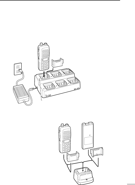
DRapid charging with the BC-121+AD-94
The optional BC-121 allows up to 6 battery packs to be charged si-
multaneously. The following are additionally required.
• Six AD-94s.
• An AC adapter (may be supplied with the BC-121 depending on
version).
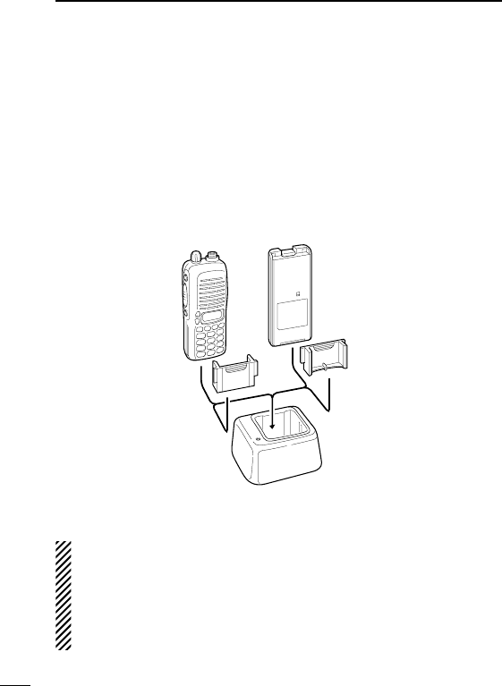
DRegular charging with the BC-146
The optional BC-146 pro-
vides regular charging of
optional battery pack with/
without transceiver.
The following is additionally
required:
• An optional AC adapter.
(A charger adapter is sup-
plied with BC-146.)
MULTI-CHARGER
AC adapter
(purchased
separately)
Charge indicator
(each indicator functions independently)
Turn power OFF.
Check orientation
for correct charg-
ing.
(Insert togeth-
er with charging
adapter.)
Turn power OFF.
BC-137

9
3BATTERY PACKS
‘‘Charging NOTE
Prior to using the transceiver for the first time, the battery pack must
be fully charged for optimum life and operation.
• Recommended temperature range for charging:
+10°C to +40°C (50°F to 140°F).
• Use the supplied charger or optional charger (BC-119/BC-121 for
rapid charging, BC-146 for regular charging) only. NEVER use
other manufacturers’chargers.
The optional BP-209, BP-210 or BP-222 battery packs include
rechargeable Ni-Cd(Ni-MH: BP-210) batteries and can be charged
approx. 300 times. Charge the battery pack before first operating
the transceiver or when the battery pack becomes exhausted.
If you want to charge the battery pack more than 300 times, the fol-
lowing points should be observed:
• Avoid over charging. The charging period should be less than
24hours.
• Use the battery until it becomes almost completely exhausted
under normal conditions. We recommend battery charging after
transmitting becomes impossible.
DDBattery pack life
When the operating period becomes extremely short even after
charging the battery pack fully, a new battery pack is needed.
10
3
BATTERY PACKS
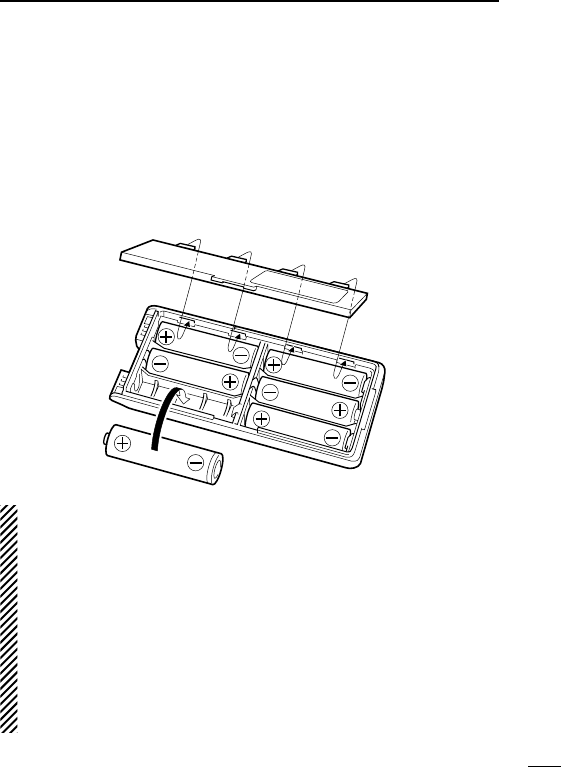
‘‘Battery case (Option)
When using a BP-208 OPTIONAL BATTERY CASE attached to the
transceiver, install 6 AA (R6) size alkaline batteries as illustrated
below.
NOTE: Output power is automatically reduced to 1 W to retains suffi-
cient power in case of emergency, etc.
DDCAUTIONS
• Use ALKALINE batteries only.
• Make sure all battery cells are the same brand, type and ca-
pacity.
• Never mix old and new batteries.
Either of the above may cause a fire hazard or damage the
transceiver. If ignored.
• Never incinerate used battery cells since internal battery gas
may cause them to rupture.
• Never expose a detached battery case to water.
If the battery case gets wet, be sure to wipe it dry before using.

11
4PROGRAMMABLE FUNCTIONS
‘‘General
In the following explanations, programmable function names are
bracketed, the specific switch used to activate the function depends
on programming.
DDKEYPAD LOCK FUNCTION
This function locks access to all programmable switches (except
the switch assigned for the lock function).
:
Push and hold the [LOCK] switch for 1 sec. to toggle the lock func-
tion ON and OFF.
• This function may be inhibited on some channels.
DDPRIORITY CHANNEL
This function is used to select a pre-programmed channel at the
push of a switch.
Push the [PRIORITY] switch to select the priority channel.
• “PRIO” appears briefly, then the priority channel is automatically
selected.
DDSCAN FUNCTION
The scan function allows you to search a pre-programmed group
of channels for signals.
Push the [SCAN] switch to start/stop scan.
• Scan pauses on a channel when receiving a signal.
• Depending on programming, a message may appear while scan-
ning.
• “Lockout SCAN” (pre-programmed list SCAN) or “Priority SCAN”
can be pre-programmed.
• When the “Power-save function” is activated, the transceiver
checks all pre-programmed channels then returns to the “Power-

12
4
PROGRAMMABLE FUNCTIONS
save function” again.
DDHIGH/LOW POWER OUTPUT
This function selects high or low power for a channel.
Push the [HIGH/LOW] switch to toggle between high and low
power.
13
4PROGRAMMABLE FUNCTIONS
DDMONITOR AUDIBLE FUNCTION
The monitor function allows you to open the transceiver’s squelch
manually to check whether a channel is busy or not. The trans-
ceiver has 2 conditions for receive standby:
Audible condition:
This condition mutes audio ONLY when
no carrier is present. You can receive (or
monitor) any signals on a channel.
• Push and hold the [MONI/AUDI], switch
to select the audible condition.
Any audio mute functions are cancelled
while pushing the [MONI/AUDI] switch.
Inaudible condition:
This condition mutes ALL signals except
those directed to you. Therefore you
should check a channel’s condition (busy
or not) with the monitor function before
transmitting.
• Push the [MONI/AUDI] switch momen-
tarily to select the inaudible condition.
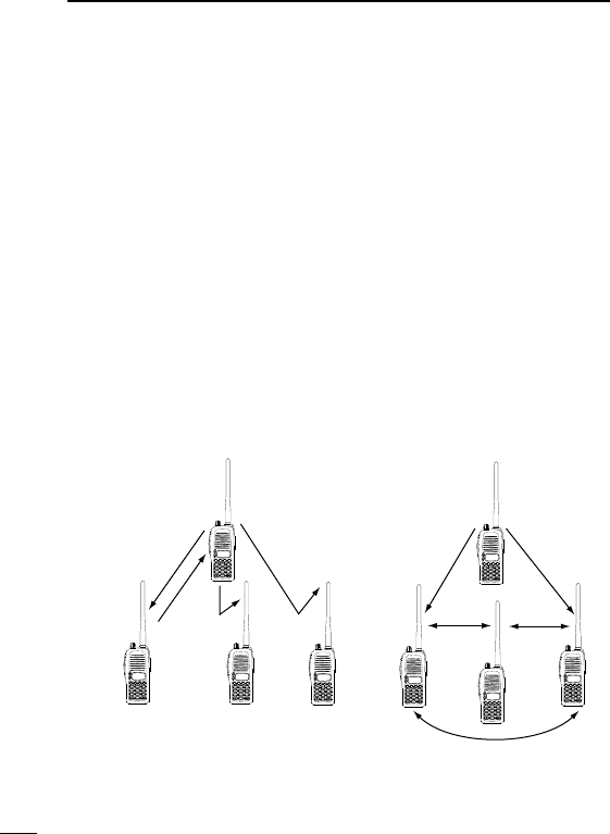
DDTALK AROUND
The talk around function changes duplex channels to simplex chan-
nels.
• Duplex allows you to contact your base station, repeaters, etc.
• Simplex allows you to contact other portable transceivers directly
(portable-to-portable contact).
Push the [TALK AROUND] switch one or more times to toggle the
function ON and OFF.
All signals are
received
2
3
45
6
789
0
1
P0P1P2P3
Only signals
containing
the proper
tone are
received
2
3
45
6
789
0
1
P0P1P2P3

14
4
PROGRAMMABLE FUNCTIONS
DDDTMF TRANSMISSION
This function allows you to send a pre-programmed DTMF code to
control a repeater, open another transceiver’s squelch, etc.
Manual transmission:
Push desired digit keys in sequence while pushing [PTT].
• Pushing [PTT] may not be necessary depending on programming.
Automatic pre-programmed transmission:
Push the [DTMF Autodial] switch to send a DTMF code.
DDEMERGENCY FUNCTION
The emergency function allows you to send your ID quickly and
easily to your Base Station, etc. in case of emergency.
Push and hold the [EMERGENCY SINGLE/REPEAT] switch for 1
sec. to activate the emergency function.
• The transceiver selects a pre-programmed channel, then sends
an emergency signal to your Base Station.
• The pre-programmed channel remains selected until a control sig-
nal is received from the Base Station, or power is turned OFF.
• The emergency call is repeatedly transmitted at pre-programmed
intervals.
DDMR-CH1–4
Tush to ..

16
5
CONVENTIONAL OPERATION
‘‘Receiving and transmitting
NOTE: Transmitting without an antenna may damage the trans-
ceiver. See p.1 for antenna attachment.
Turn power ON as described on p. 1.
Receiving:
qSelect a desired channel.
wListen for a transmission and adjust [VOL] to a comfortable lis-
tening level.
• When no transmission is heard, push and hold monitor while
adjusting [VOL] (your transceiver may not be programmed with
the monitor function).
The transceiver is now set to receive desired calls on the selected
channel.
Transmitting:
Wait for the channel to become clear to avoid interference.
eWhile pushing and holding [PTT], speak into the microphone at a
normal voice level.
• When a tone signalling system is used, the call procedure de-
scribed at right may be necessary.
rRelease [PTT] to return to receive.
IMPORTANT: To maximize the readability of your transmitted sig-
nal, pause a few sec. after pushing [PTT], hold the microphone 10
to 15 cm from your mouth and speak at a normal voice level.
17
5CONVENTIONAL OPERATION
‘‘Call procedure
When your system employs tone signalling (excluding CTCSS and
DTCS), the call procedure may be necessary prior to voice trans-
mission. The tone signalling employed may be a selective calling
system which allows you to call specific station(s) only and prevent
unwanted stations from contacting you.
qSelect the desired Tx code channel or 5-tone code according to
your System Operator’s instructions.
• This may not be necessary depending on programming.
• Refer to the next page for selection.
wPush the call switch (assigned to one of the dealer programma-
ble switches: [Upper] and [Lower]).
eAfter transmitting a 5-tone code, the remainder of your commu-
nication can be carried out in the normal fashion.
2
3
45
6
789
0
1
P0P1P2P3
2
3
45
6
789
0
1
P0P1P2P3
2
3
45
6
789
0
1
P0P1P2P3
2
3
45
6
789
0
1
P0P1P2P3
2
3
45
6
789
0
1
P0P1P2P3
2
3
45
6
789
0
1
P0P1P2P3
2
3
45
6
789
0
1
P0P1P2P3
2
3
45
6
789
0
1
P0P1P2P3
Non-selective calling
Selective calling

18
5
CONVENTIONAL OPERATION
‘‘Transmitting notes
DDTIME-OUT TIMER
After continuous transmission for a pre-programmed period, the
time-out timer is activated, causing the transceiver to stop transmit-
ting and automatically select receive.
DDPENALTY TIMER
Once the time-out timer is activated, transmission is further inhibited
for a period determined by the penalty timer.

22
7
OTHER FUNCTIONS
‘‘CODE SQUELCH
DDCode squelch
This conveniently eliminates unwanted audio and is useful in group
activities or security related activities where unwanted output can
be a problem. The function is similar to a CTCSS tone squelch.
In order to use the above functions, cloning is necessary via a PC
using the optional CS-F11 cloning software. Using this software, the
transceiver’s model, individual RX Code CH, TX Code CH, Special
Tone Link2 (must be ‘E’) on 5Tone screen, 5Tone Signaling Form
on Memory-CH screen, Log, RX C-No, Key&Display, Common Au-
toReset TimerB, and other settings related to operation can be set.
Refer to the HELP file that comes with the CS-F11 CLONING SOFT-
WARE for available settings.

24
9
CLONING
‘‘Cloning
Cloning allows you to quickly and easily transfer the programmed
contents from one transceiver to another transceiver; or data from
PC to a transceiver using the optional CS-F11 CLONING SOFT-
WARE.
DDTransceiver-to-transceiver cloning
qConnect the optional OPC-474 CLONING CABLE with adapter
plugs to the [SP] jack of the master and slave transceivers.
•The master transceiver is used to send data to the slave trans-
ceiver.
wWhile pushing [PTT] and [Upper], turn the transceiver’s power
on to enter cloning mode (master transceiver only–power ON
only for slave transceiver).
ePush [PTT] on the master transceiver.
•When cloning is finished, “Beep” tone emits tow times.
NOTE: DO NOT push the [PTT] on the slave transceiver during
cloning. This will cause a cloning error.
rWhen cloning is finished, turn power off, then on again to return
to normal operation.
DDPC-to-transceiver cloning
Please refer to the HELP file that comes with the CS-F11 CLONING
SOFTWARE.
CAUTION: Imprudent cloning operation causes a cloning error.
In such a case, memory contents may be lost. Cloning must
then be repeated.

25
10 OPTION / PC to Tr cloning
‘‘Options
DDBATTERY PACKS
• BP-208 BATTERY CASE
Allows a set of Alkaline batteries to operate the handheld when
charging the rechargeable battery or in emergencies, etc. 6 AA
(R6) cells are required.
• BP-209 Ni-Cd BATTERY PACK
7.2 V/1100 mAh Ni-Cd battery pack, allows more than 8 hours op-
eration.
• BP-210 Ni-MH BATTERY PACK
7.2 V/1650 mAh Ni-MH battery pack, allows approx. 11 hours op-
eration.
• BP-222 Ni-Cd BATTERY PACK
7.2 V/600 mAh Ni-Cd battery pack, allows approx. 5.5 hours op-
eration (Same as supplied with 2 W models).
DDCHARGER
• BC-119 DESKTOP CHARGER
For rapid charging of battery packs. An AC adapter is supplied
with the charger. Charging time: 1.5 to 2 hrs.
• BC-121 MULTI-CHARGER
For rapid charging up to 6 battery packs simultaneously. An AC
adapter may be supplied depending on version. Six AD-94’s are
necessary. Charging time: 1.5 to 2 hrs.
•AD-94 CHARGER ADAPTOR
• BC-146 DESKTOP CHARGER
For regular charging of BP-209 (Ni-Cd), BP-210 (Ni-MH) and BP-
222 (Ni-Cd).
• BC-144 DESKTOP CHARGER
For rapid charging of BP-209 (Ni-Cd) and BP-210 (Ni-MH).

26
10
OPTION
DDOTHER OPTIONS
• HM-46L/HM-75A SPEAKER-MICROPHONES
Combination speaker-microphone that provides convenient oper-
ation while hanging the transceiver from your belt.
• HS-51 HEAD SET
Allows you hands-free operation. Includes PTT and TOT.
• SP-13 EARPHONE
Provides clear receive audio in noisy environments.
• MB-68 BELT CLIP
Same as that supplied with the transceiver.
• MB-74 BELT CLIP
Exclusive alligator-type belt clip.
• AD-98FSC ANTENNA CONNECTOR ADAPTER
Allows you to connect a BNC-type antenna.
• CS-F11 CLONING SOFTWARE
Allows you to clone the memory contents of an IC-F11/S, IC-
F21/S by PC editing.
• OPC-474 CLONING CABLE
Cloning cable for transceiver to transceiver
• OPC-478 CLONING CABLE
Cloning cable for PC to transceiver.
1-1-32 Kamiminami, Hirano-ku, Osaka 547-0003 Japan
A-6021?-1EX
Printed in Japan
© 2001 Icom Inc.
Count on us!
IC-F11/F21S series