ICOM orporated IC-F30G Handheld Transmitter held to face User Manual IC F30G series
ICOM Incorporated Handheld Transmitter held to face IC F30G series
UserManual.wiki
>
ICOM orporated
>
IC-F30G User Manual
>
Manual
Contents
1.
Manual
2.
revised users manual with RFSafety Training
3.
Revised Manual
Manual
Navigation menu
Upload a User Manual
Namespaces
Wiki Guide
HTML
PDF
Info
Views
User Manual
Discussion / Help
Navigation
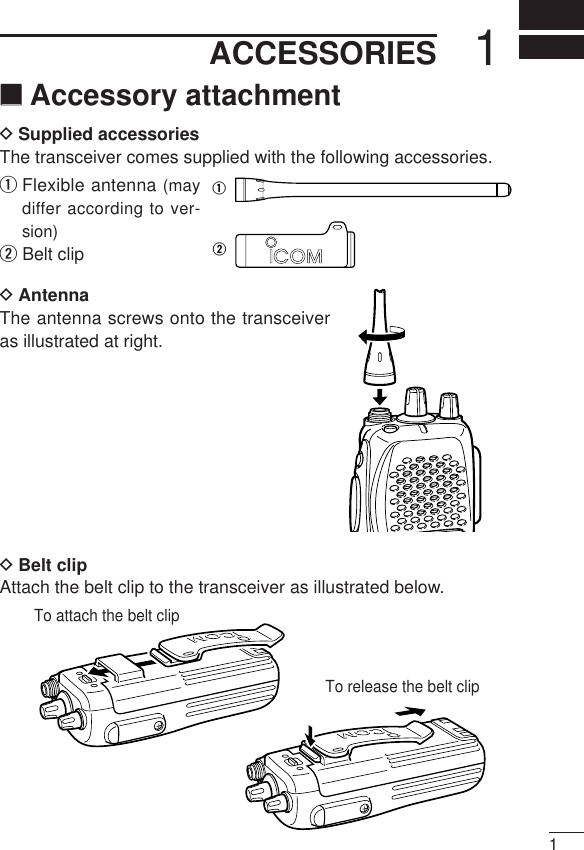
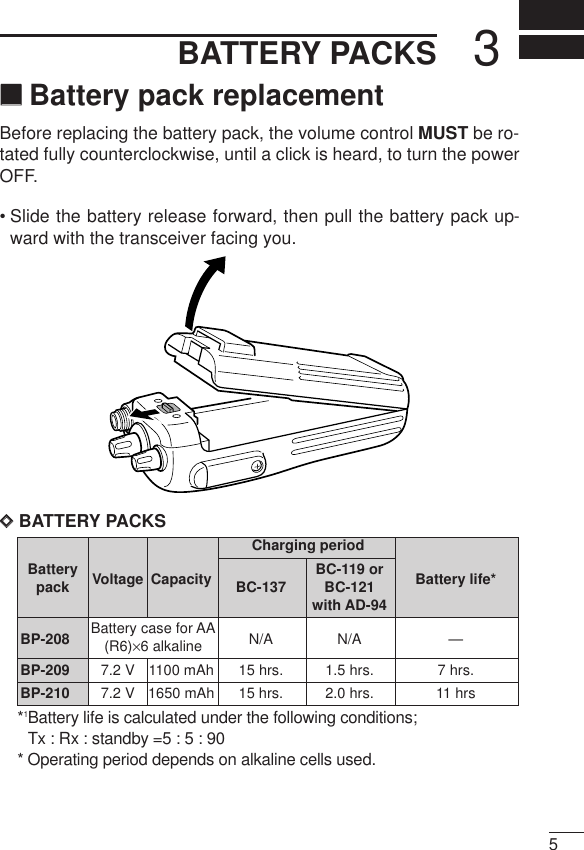
![32PANEL DESCRIPTIONqANTENNA CONNECTORConnects the supplied antenna.wDEALER-PROGRAMMABLE KEY [F0 (Red)]eDEALER-PROGRAMMABLE KEY [F1 (Black)]rPTT SWITCH [PTT]Push and hold to transmit; release to receive.tDEALER-PROGRAMMABLE KEYS [F2 (Black)], [F3 (Black)]• Push to select the operating channel.• Can be programmed as [ ✱]/[ # ]. (SmarTrunk mode only)yDEALER-PROGRAMMABLE KEYS [P0]/[P1]/[P2]/[P3]Can each be programmed for one of several functions by yourIcom Dealer.u10-KEY PAD (IC-F30GT/IC-F40GT only)Used to enter DTMF codes, the operating channel, etc.iFUNCTION DISPLAYDisplays variety of information such as, operating channel num-ber/names, 5-tone code, remaining battery power, DTMF num-bers, transmit output power setting, Audible indication, etc.NOTE: Above functions depend on pre-setting.oMULTI CONNECTORConnect optional speaker-microphone, etc..!0 TRANSMIT/BUSY INDICATORLights red while transmitting; lights green while receiving a sig-nal, or squelch is open.!1 VOLUME CONTROL [VOL]Turns power ON and adjusts the audio level.!2 ROTARY SELECTOR [SEL]Selects operating channel or bank. Depends on setting.](https://usermanual.wiki/ICOM-orporated/IC-F30G.Manual/User-Guide-111834-Page-7.png)
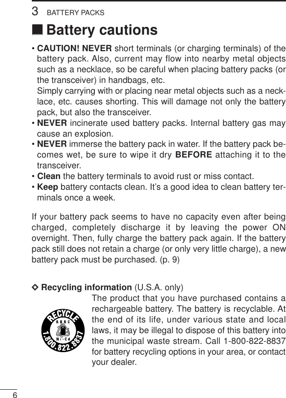
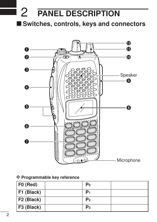
![114PROGRAMMABLE FUNCTIONS‘‘GeneralIn the following explanations, programmable function names arebracketed, the specific switch used to activate the function dependson programming.DDKEYPAD LOCK FUNCTIONThis function locks access to all programmable switches (exceptthe switch assigned for the lock function).Push and hold the [Lock] switch for 1 sec. to toggle the lock functionON and OFF.• “ ”appears while the lock function is ON.• This function may be inhibited on some channels.DDPRIORITY CHANNELThis function is used to select a pre-programmed channel at thepush of a switch.Push the [Priority A/A (Rewrite)/B] switch to select the priority chan-nel.• “Prio A” or “Prio B”appears briefly, then the priority channel is auto-matically selected.DDSCAN FUNCTIONThe scan function allows you to search a pre-programmed groupof channels for signals.Push the [Scan A/B] switch to start/stop scan.• Scan pauses on a channel when receiving a signal.• Depending on programming, a message may appear while scanning.• “Lockout SCAN” (pre-programmed list SCAN) or “Priority SCAN” canbe pre-programmed.• When the “Power-save function” is activated, the transceiver checksall pre-programmed channels then returns to the “Power-save func-tion” again.](https://usermanual.wiki/ICOM-orporated/IC-F30G.Manual/User-Guide-111834-Page-15.png)
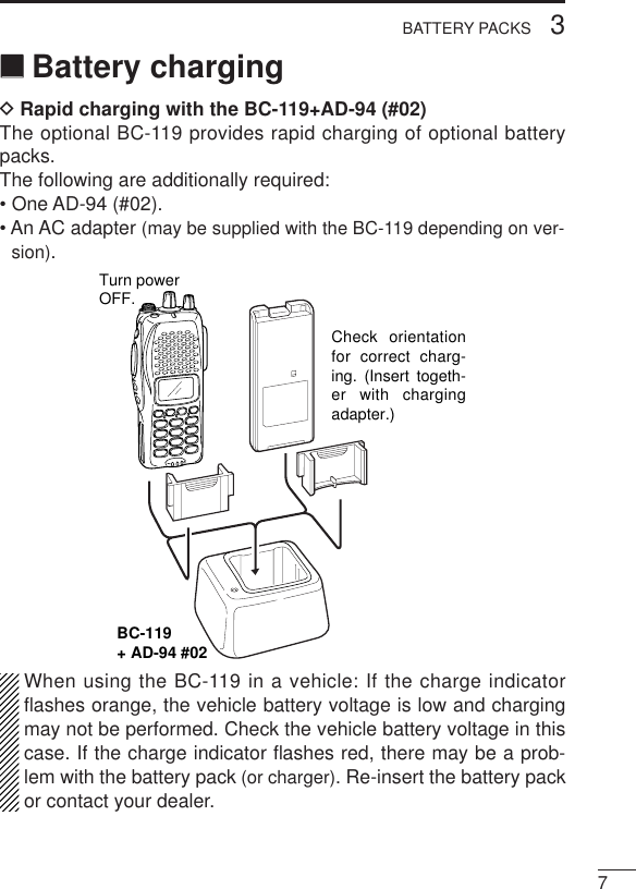
![124PROGRAMMABLE FUNCTIONSDDHIGH/LOW POWER OUTPUTThis function selects high or low power for a channel.Push the [High/Low] switch to change transmit output power be-tween high, low1 and low2 power.• “ ” appears when low1 or low2 output power is selected.DDSCRAMBLER FUNCTION(optional UT-109 (#02)* or UT-110 (#02)* is required.)This function provides higher communication security.UT-109: Non-rolling type. 32 code numbers are available.UT-110: Rolling type. 1020 (4 groups ×255) code numbers areavailable.Push the [Scrambler] switch to toggle the function ON and OFF.NOTE: NEVER use #01 Low AF level versions, as they are notcompatible](https://usermanual.wiki/ICOM-orporated/IC-F30G.Manual/User-Guide-111834-Page-16.png)
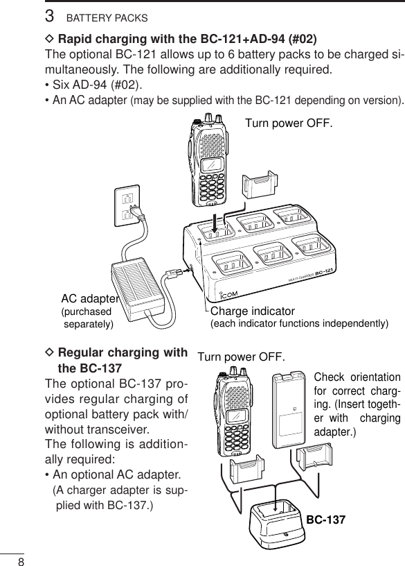
![134PROGRAMMABLE FUNCTIONSDDMONITOR AUDIBLE FUNCTIONThe monitor function allows you to open the transceiver’s squelchmanually to check whether a channel is busy or not. The trans-ceiver has 2 conditions for receive standby:Audible condition:This condition mutes audio ONLY whenno carrier is present. You can receive (ormonitor) any signals on a channel.• Push and hold the [Moni] (LMR) or[Moni (Audi)] (PMR) switch to select theaudible condition.Any audio mute functions are cancelledwhile pushing the [Moni] (LMR) or[Moni (Audi)] (PMR) switch.Inaudible condition:This condition mutes ALL signals exceptthose directed to you. Therefore youshould check a channel’s condition (busyor not) with the monitor function beforetransmitting.• Push the [Moni] (LMR) or [Moni (Audi)](PMR) switch momentarily to select the in-audible condition.DDTALK AROUNDThe talk around function changes duplex channels to simplex chan-nels.• Duplex allows you to contact your base station, repeaters, etc.• Simplex allows you to contact other portable transceivers directly(portable-to-portable contact).Push the [Talk Around] switch to toggle the function ON and OFF.All signals are received.Only signals containing the proper tone are received.](https://usermanual.wiki/ICOM-orporated/IC-F30G.Manual/User-Guide-111834-Page-17.png)
![144PROGRAMMABLE FUNCTIONSDDDTMF TRANSMISSIONThis function allows you to send a pre-programmed DTMF code tocontrol a repeater, open another transceiver’s squelch, etc.Manual transmission:Push the desired digit keys in sequence while pushing [PTT].• Pushing [PTT] may not be necessary depending on programming.Automatic pre-programmed transmission:qPush the [DTMF Autodial] switch to select DTMF autodial mode,then push [CH Up] or [CH Down] to select the desired channel.wPush the [DTMF Autodial] switch to send a DTMF code.DD DTMF RE-DIAL FUNCTIONThis function allows you to transmit the last-used DTMF code at thepush of a key.Push the [Re-dial] switch momentarily to activate the function.• The previously transmitted DTMF code is automatically transmitted.• If no code has been transmitted since turning the power ON, this func-tion does not activate.DDEMERGENCY FUNCTIONThe emergency function allows you to send your ID quickly andeasily to your Base Station, etc. in case of emergency.Push and hold the [Emergency Single/Repeat] switch for 1 sec. toactivate the emergency function.• The transceiver selects a pre-programmed channel, then sends anemergency signal to your Base Station.• The pre-programmed channel remains selected until a control signal isreceived from the Base Station, or power is turned OFF.• The emergency call is repeatedly transmitted at pre-programmed in-tervals.](https://usermanual.wiki/ICOM-orporated/IC-F30G.Manual/User-Guide-111834-Page-18.png)
![154PROGRAMMABLE FUNCTIONSDDDISPLAY LIGHTINGThe function display has 3 backlight conditions.ON : Backlight turns ON continuously. OFF : No backlight is available.AUTO : When any key, except [PTT], is pushed, the backlightturns ON for 5 sec. automatically.DDSmarTrunk IITM functionsThis transceiver provides SmarTrunk IITM functions.(Optional UT-105 SmarTrunk IITM Logic Boardis required.)The optional UT-105 allows communication over conventionalchannels or SmarTrunk IITM channels. Select a channel bank forSmarTrunk IITM before trunking operation.To toggle SmarTrunk IITM channels and conventional channels, pushthe [Bank] switch one or more times.• Scanning starts when a channel bank for SmarTrunk IITM is selected.• Contact your dealer for channel bank details. (See p. 19 for more detailed operation.)](https://usermanual.wiki/ICOM-orporated/IC-F30G.Manual/User-Guide-111834-Page-19.png)
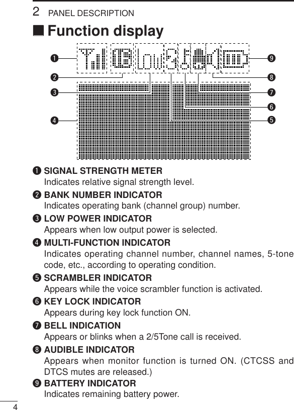
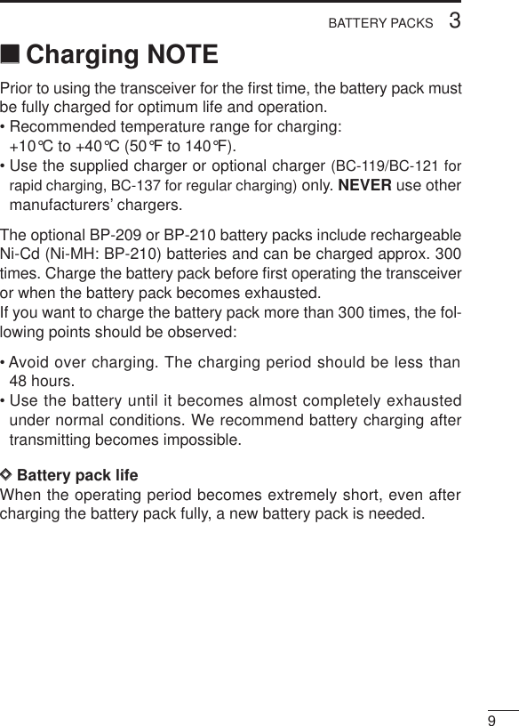
![165CONVENTIONAL OPERATION‘‘Receiving and transmittingNOTE: Transmitting without an antenna may damage the trans-ceiver. See p. 1 for antenna attachment.Turn power ON as described on p. 3.Receiving:qPush [CH Up]/[CH Down], or rotate the [SEL] to select a chan-nel.wListen for a transmission and adjust [VOL] to a comfortable lis-tening level.• When no transmission is heard, push and hold monitor while ad-justing [VOL] (your transceiver may not be programmed with themonitor function).The transceiver is now set to receive desired calls on the selectedchannel.Transmitting:Wait for the channel to become clear to avoid interference.eWhile pushing and holding [PTT], speak into the microphone at anormal voice level.• When a tone signalling system is used, the call procedure de-scribed at right may be necessary.rRelease [PTT] to return to receive.IMPORTANT: To maximize the readability of your transmitted sig-nal, pause a few seconds. after pushing [PTT], holdthe microphone 2 to 4 in. (5 to 10 cm) from yourmouth and speak at a normal voice level.](https://usermanual.wiki/ICOM-orporated/IC-F30G.Manual/User-Guide-111834-Page-20.png)
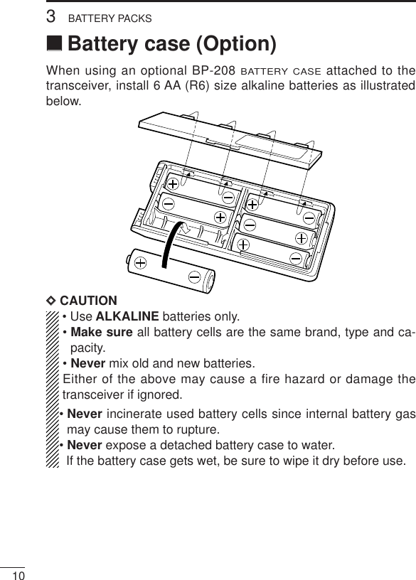
![175CONVENTIONAL OPERATION‘‘Call procedureWhen your system employs tone signalling (excluding CTCSS andDTCS), the call procedure may be necessary prior to voice trans-mission. The tone signalling employed may be a selective callingsystem which allows you to call specific station(s) only and preventunwanted stations from contacting you.qSelect the desired Tx code channel or 5-tone code according toyour System Operator’s instructions.• This may not be necessary depending on programming.• Refer to the next page for selection.wPush the call switch (assigned to one of the dealer programma-ble switches: [P0], [P1], [P2], [P3], [F2] and [F3]).eAfter transmitting a 5-tone code, the remainder of your commu-nication can be carried out in the normal fashion.Selective calling Non-selective calling](https://usermanual.wiki/ICOM-orporated/IC-F30G.Manual/User-Guide-111834-Page-21.png)
![196SmarTrunk IITM OPERATION‘‘Basic operationThese features are enabled by your Dealer or System operator andmay not be available in your system. Contact your Dealer for details.Push the [Bank] switch one or more times to select a channel bankfor conventional channels or SmarTrunk II™ channels.• Scanning starts when a channel bank for SmarTrunk IITM is selected.DDPTT dispatch operation*1qPush [PTT] once (without dialling) to initiate a dispatch call.wBegin talking after you hear three beeps (one short, high-pitched, two very-short, low-pitched).eReceiving a dispatch call is indicated by the same three-beepsequence. • It is not necessary to push [M] to answer a dispatch call.DDSystem busy indicationIf all channels are busy, three low beeps sound after you initiatea call. Try the call again later.DDReceiving a subscriber-to-subscriber call*1When you hear ringing, push [M] to answer.• For a group call, you hear a short ring followed by two short beeps.You do not have to answer a group call to hear it over the air.DDReceiving a landline-to-subscriber call*1When you hear ringing, push [M] to answer.• For a group call, you hear a short ring followed by two short beeps.You do not have to answer a group call to hear it over the air.DDTerminating a call*1After completing a call, push [#] to disconnect (hang up).IMPORTANT: If one person in the conversation terminates a call,all participants will be cut off.](https://usermanual.wiki/ICOM-orporated/IC-F30G.Manual/User-Guide-111834-Page-23.png)
![206SmarTrunk IITM OPERATIONDDLast number redial*1Push [M], [M] to automatically redial the last number called.• A high-pitched beep indicates that the number is accepted.DDTurbo SpeeDialTo automatically dial a commonly used number with one push:• Push one of the turbo SpeeDial keys.DDProgramming memory speed dial qPush and hold [M] until you hear a high-pitched beep.wEnter the memory location (0–9, A, B, C, D), the telephone orsubscriber number, then [1], [M] (or [3], [M] if for another sys-tem subscriber).• A high-pitched beep indicates successful programming.• Memories [A]–[D] are used for the Turbo SpeeDial.NOTE: This function is available for the IC-F30GT/IC-F40GTonly.DDMemory speed-dialling*2To automatically dial a commonly used number from memory:• Push [M] followed by the memory location (0–9).DDClear channel alerting*1If all channels are busy, the transceiver automatically beginssearching for an open channel and beeps every ten seconds.When two short beeps (low-pitched, then high-pitched) areheard, a channel is available. Push [M], [M] immediately to redialthe last number.DDEmergency call*2Push [0], [M] to initiate an emergency call.• Contact your Dealer for details.](https://usermanual.wiki/ICOM-orporated/IC-F30G.Manual/User-Guide-111834-Page-24.png)
![216SmarTrunk IITM OPERATIONDDPlacing a telephone call*2Enter the phone number followed by [1], [M].• A high-pitched beep indicates that the number is accepted.• When the called party answers, push the [PTT] switch to talk, andrelease it to listen.DDCalling another local system subscriber*2Enter the subscriber number followed by [3], [M].• A high-pitched beep indicates that the number is accepted.• You hear ringing, then two short beeps when the subscriber an-swers.• If the other subscriber is on another call or out of range, you hear afast busy signal and the call terminates automatically.*1: This function is available for the IC-F30GS/IC-F40GS when the[F2]/[F3] keys are assigned the [M]/[ # ] key functions.*2: This function is available for the IC-F30GT/IC-F40GT only.Use the Turbo SpeeDial function instead.For additional operating instructions, contact your Dealer orSystem Operator.](https://usermanual.wiki/ICOM-orporated/IC-F30G.Manual/User-Guide-111834-Page-25.png)