ICOM orporated IC-F620-2 IC-F620 User Manual
ICOM Incorporated IC-F620 Users Manual
UserManual.wiki
>
ICOM orporated
>
IC F620 2 User Manual
Users Manual
Navigation menu
Upload a User Manual
Namespaces
Wiki Guide
HTML
PDF
Info
Views
User Manual
Discussion / Help
Navigation
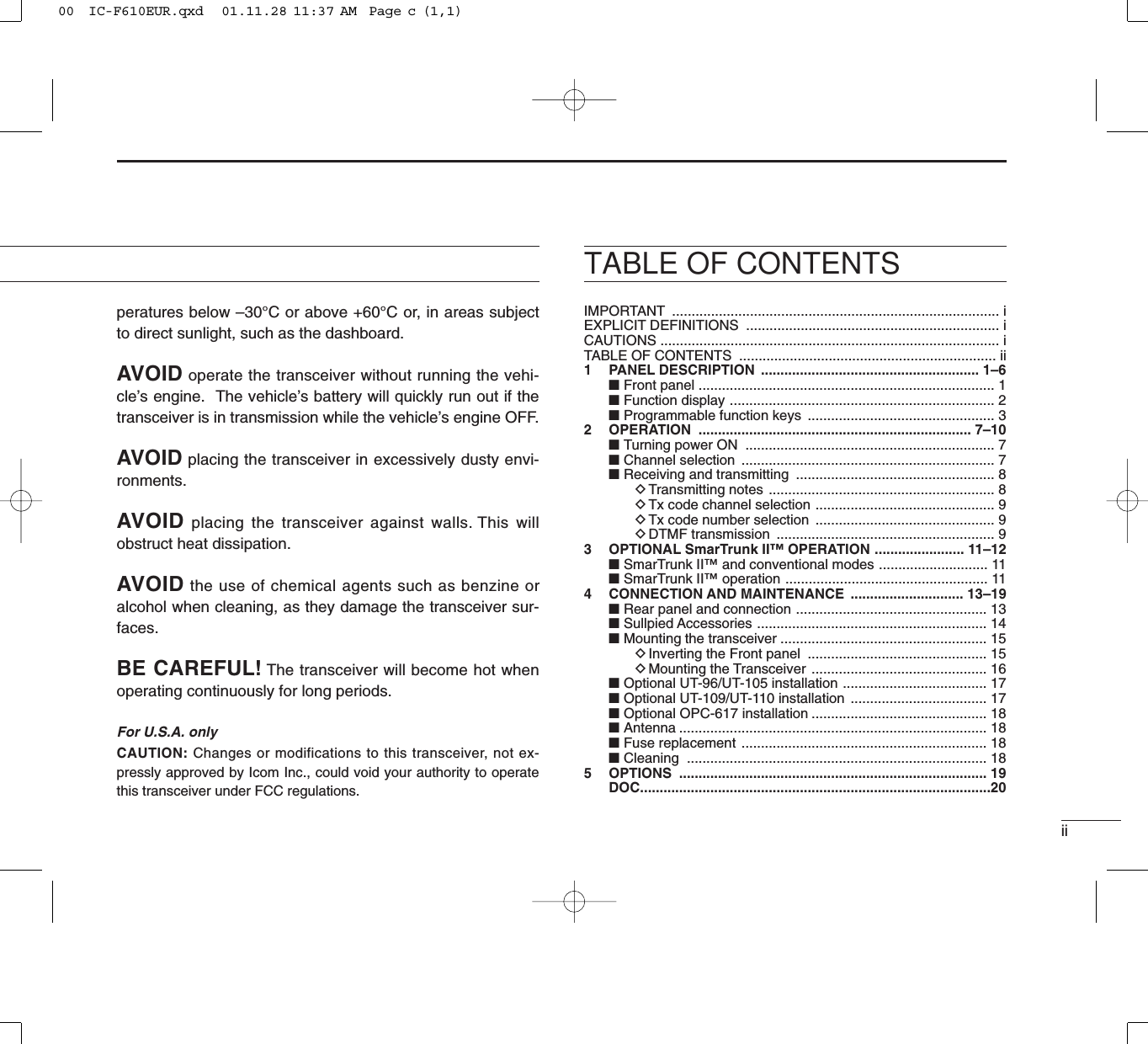
![11PANEL DESCRIPTIONuMicrophone connectoryPower switch tProgrammable keys [P0] to [P4]rRight UP/DOWN keyseFunction displaywLeft UP/DOWN keysqAF volume control knob■Front panelqAF VOLUME CONTROL KNOBTurn the knob to adjust the audio output level.• Minimum audio level is pre-programmed.wLEFT UP/DOWN [∫∫]/[√√] KEYS•Push to select the operating channel.•Can be programmed for one of several functions by yourdealer. (Same as [P0] to [P4] keys)eFUNCTION DISPLAYDisplays variety of information, such as operating channelnumber/names, 5-tone code, DTMF numbers and audiblecondition, etc.NOTE: The above functions depend on pre-setting.rRIGHT UP/DOWN [ ]/[ ] KEYS•Push to select the operating channel.•Can be programmed for one of several functions by your00 IC-F610EUR.qxd 01.11.28 11:37 AM Page d (1,1)](https://usermanual.wiki/ICOM-orporated/IC-F620-2/User-Guide-220410-Page-5.png)
![21PANEL DESCRIPTIONdealer. (Same as [P0] to [P4] keys)tDEALER-PROGRAMMABLE KEYS [P0] to [P4]Can each be programmed for one of several functions byyour Icom dealer.yPOWER SWITCHPush to turns the power ON and OFF.• The following functions are available at power ON as options:•Automatic scan start•Password prompt•Set modeuMICROPHONE CONNECTORConnect the supplied microphone or optional DTMF micro-phone for SmarTrunk II™operation here.NEVER connect other microphones. The pin assignmentsmay be different and the transceiver may be damaged.MICROPHONEThe supplied microphone has a PTT switch and a hangerhook. • The following functions are available when the microphone is on oroff hook:- Automatic scan start when hung on.- Automatic priority channel selection when hung off.- Sets to ‘Inaudible’condition (mute condition) when hung on.- Sets to ‘Audible’condition (un-mute condition) when off.■Function displayqTRANSMIT INDICATOR•Appears while transmitting or sending a 5-tone code.•When internal temperature increases to a specific level, thetransmit indicator blinks to indicate that the power down cir-cuit has been activated.wBUSY INDICATORAppears while the channel is busy.eSIGNAL STRENGTH METERIndicates relative signal strength level.rLOW POWER INDICATORAppears when low output power is selected.tAUDIBLE INDICATORAppears when the channel is in the ‘Audible’condition(unmute condition).yCOMPANDER INDICATORAppears when compander function is activated.q w e r t y u i o !0 !1!2!300 IC-F610EUR.qxd 01.11.28 11:37 AM Page e (1,1)](https://usermanual.wiki/ICOM-orporated/IC-F620-2/User-Guide-220410-Page-6.png)
![31PANEL DESCRIPTIONuSCRAMBLER INDICATORAppears when scrambler function is activated. (Optional UT-109 (#02)/UT110 (#02) SCRAMBLER UNIT is required.)i2/5TONE INDICATORAppears when specified 2/5tone call is received.o!0 LTR INDICATORAppears when LTR function is selected.!1 SHORT MESSAGE INDICATORAppears when a short message is received.!2 ALPHANUMERIC DISPLAYDisplays the CH number, 5-tone indication, DTMF numbers,Audible indication, etc.NOTE: When the alphanumeric display blinks and trans-mitting becomes impossible. In this case, check that theantenna is not miss-matched or that DC battery voltagehas not dropped below 8 V!3 ACTIVATED KEY INDICATORAppears or blinks when the key under this indicator is acti-vated.■Programmable function keysThe following functions can be assigned to [P0], [P1], [P2],[P3], [P4], [∫∫], [√√], [ ] and [] programmable functionkeys.Consult your Icom Dealer or System operator for details con-cerning your transceivers programming.In the following explanations, programmable function namesare bracketed, the specific switch used to activate the func-tion depends on programming.CH UP AND DOWN KEYS • Select an operating channel.• Select a transmit code channel after pushingthe [TX CH] key.• Select a DTMF channel after pushing the[DTMF] key.• Select a scan group after pushing and holdingthe [SCAN] key.OPERATING CHANNEL KEYSSelect an operating channel directly.PRIORITY CHANNEL KEYSSelect priority A or priority B channel with eachpush.[CH UP][CH DN][CH1][CH2][CH3][CH4][PRI A]00 IC-F610EUR.qxd 01.11.28 11:37 AM Page f (1,1)](https://usermanual.wiki/ICOM-orporated/IC-F620-2/User-Guide-220410-Page-7.png)
![41PANEL DESCRIPTIONMONITOR KEYActivates one of (or two of) the following func-tions on each channel independently:• Push and hold the key to unmute the channel (audiois emitted; ‘Audible’condition).• Push the key to toggle the mute and unmute condi-tions (toggles ‘Audible’and ‘Inaudible’).• Push the key to mute the channel (sets to ‘Inaudible’only).• Push the key to unmute the channel (sets to ‘Audible’only).• Push the key after the communication is finished tosend a ‘reset code’.NOTE: The unmute condition (‘Audible’condi-tion) may automatically return to the mute condi-tion (‘Inaudible‘ condition) after a specified peri-od.WIDE/NARROW KEYPush [W/N] to toggle bandwidth between wide ornarrow.•This function is available for W/N versions only.OUTPUT POWER SELECTION KEYSSelect the transmit output power temporarily orpermanently depending on the pre-setting.[MONI][W/N][H/L]BANK KEYSelect a bank.• When the optional UT-105 is installed, push oneor more times to select a channel bank for con-ventional channels or SmarTrunk II™channels.SCAN START/STOP KEYPush this key to start scanning; and push againto stop.NOTE: Place the microphone on hook to startscanning.Take the microphone off hook to stop scanning.Push and hold this key to indicate the scangroup, then push to select the desired group.SCAN TAG KEYAdds or deletes the selected channel to the scangroup.LOCK KEYElectronically locks all programmable keysexcept the following:•[CALL] (incl. CAL A and CAL B), [MONI] and[EMER] keys.[Bank][SCAN A][SCAN B][TAG][LOCK]00 IC-F610EUR.qxd 01.11.28 11:37 AM Page g (1,1)](https://usermanual.wiki/ICOM-orporated/IC-F620-2/User-Guide-220410-Page-8.png)
![51PANEL DESCRIPTION• Ask your Dealer or System Operator for the out-put power level for each selection.TALK AROUND KEYTurns the talk around function ON and OFF.• The talk around function equalises the transmitfrequency to the receive frequency for mobile-to-mobile communication.CALL KEYSTransmit a 5-tone call.• Call transmission is necessary before you callanother station depending on your signalingsystem.• The [CAL A] and/or [CAL B] keys may be avail-able when your system employs selective‘Individual/Group’calls. Ask your SystemOperator which call is assigned to each key.EMERGENCY KEYPush and hold the key to transmit an emergency call.• If you want to cancel the emergency call, push(or push and hold) the key again before trans-mitting the call.• The emergency call is transmitted one time onlyor repeatedly until receiving a control codedepending on the pre-setting.[ TA ][CALL][CAL A][CAL B][EMER]TX CODE KEYSelect a transmit 5-tone code (station code)channel.TX CODE CHANNEL UP/DOWN KEYPush to selects a TX code channel directory.DTMF CHANNEL SELECT KEYPush this key to select a DTMF channel.• Push this key, then select the desired DTMFchannel using the []/[]keys.Push and hold this key to transmit the selectedDTMF code.NOTE (LMR ONLY):DTMF channels 7 (EMER-GENCY) and 8 (LOG/ID) are used for ID codeand emergency code respectively, depending onyour system set up.Ask your System Operator or Dealer aboutDTMF channels 7 and 8 before using these.C. TONE CHANNEL ENTER KEYPush this key then input a continuous tone mem-ory channel number via the keypad to change thetone frequency.[TX CH][CODE][DTMF][TONE]00 IC-F610EUR.qxd 01.11.28 11:37 AM Page h (1,1)](https://usermanual.wiki/ICOM-orporated/IC-F620-2/User-Guide-220410-Page-9.png)
![61PANEL DESCRIPTIONID MEMORY READ KEYRecalls detected ID codes. • Push this key, then push []/[]for selec-tion.• Up to 5 ID's are memorized.Push and hold this key to erase all memorizedIDs.TRUNKING GROUP KEYPush to select the Trunking group.MIC COMPANDER KEYPush to toggle the mic compander function ONor OFF.SET MODE KEYChanges the contents of the items in the UserSet mode.•Push and hold [SET], push [CH UP]/[CH DN] keyto change the contents.[ID MR][GRP][COMP][SET]SCRAMBLER KEY• Push and hold to turn the voice scrambler func-tion ON.• Push to turn the voice scrambler function OFF.NOTE:• Optional UT-109 (#02) or UT-110 (#02) VOICESCRAMBLER UNIT is required.-UT-109: Non-rolling type. 32 code numbers areavailable.-UT-110: Rolling type. Provides higher communica-tion security. 1020 (4 groups x 255) code numbersare available.• This transceiver requires version #02 scram-bler units, do not install version #01, as they arenot compatible.• UT-109 and UT-110 require some PC boardmodifications. Please refer to the additionalinstallation manual.•Please contact your dealer for details.[SCRM]00 IC-F610EUR.qxd 01.11.28 11:37 AM Page i (1,1)](https://usermanual.wiki/ICOM-orporated/IC-F620-2/User-Guide-220410-Page-10.png)
![72OPERATION■Turning power ONqPush [KI] to turn the power ON.• A power-up alert tone sounds for about 1 sec. and an openingmessage may appear.wIf the transceiver is programmed for a start up passcode,input digit codes as directed by your System operator.• The keys in the diagram below can be used for password input:• The transceiver detects numbers in the same block as identical.Therefore “01234” and “56789” are the same.eWhen the “PASSWORD” indication does not clear afterinputting 4 digits, the input code number may be incorrect.Turn power off and start over in this case.■Channel selectionSeveral types are available, and the channel selectionmethod may differ according to your system set up.NON-BANK TYPE:Push the [CH Up]/[CH Down] keys to select the desired oper-ating channel, in sequence; or,push one of the [CH 1] to [CH 4] keys to select these channelsdirectly.BANK-TYPE: Push [BANK] to select the desired bank number.AUTOMATIC SCAN TYPE:Channel setting is not necessary for this type. When turningthe power ON, the transceiver automatically starts scanning.Scanning stops when receiving a call or when taking themicrophone off hook.KEY [P0] [P1] [P2] [P3] [P4]NUMBER012345678900 IC-F610EUR.qxd 01.11.28 11:37 AM Page j (1,1)](https://usermanual.wiki/ICOM-orporated/IC-F620-2/User-Guide-220410-Page-11.png)
![82OPERATION■Receiving and transmittingRECEIVING:qPush [KI] to turn the power ON.wPush [CH UP] or [CH DN] to select a channel.eWhen receiving a call, adjust the audio output level to acomfortable listening level.TRANSMITTING:rTake the microphone off hook.• 5-tone mute may be released (the ‘audible’condition is selectedand “” appears).• A priority channel may be selected automatically.tWait for the channel to become clear.• The channel is busy when “” appears.yPush the [CALL] key when initiating a call from your side.• Coded audio may be heard from the transceiver, then “”appears.• This operation may not be necessary depending on your signal-ing system. Ask your System Operator or Dealer.uWhile pushing and holding [PTT], speak into the micro-phone at your normal voice level.iRelease [PTT] to receive.IMPORTANT: To maximize the readability of your signal: (1)pause briefly after pushing [PTT], (2) hold the transceiver 15to 20 cm from your mouth, then speak into the microphone ata normal voice level.DTransmitting notes• Transmit inhibit functionThe transceiver has several lockout/inhibit functions whichrestrict transmission under the following conditions:• The channel is in mute condition (‘Inaudible’condition; “”does not appear).• Channel is busy.• No matched (or matched) CTCSS is received.• The selected channel is a ‘receive only’channel.• Time-out timerAfter continuous transmission for a pre-programmed period,the time-out timer is activated causing the transceiver to stoptransmitting and automatically select receive.• Penalty timerOnce the time-out timer is activated, transmission is furtherinhibited for a period determined by the penalty timer.00 IC-F610EUR.qxd 01.11.28 11:37 AM Page k (1,1)](https://usermanual.wiki/ICOM-orporated/IC-F620-2/User-Guide-220410-Page-12.png)
![92OPERATIONDTx code channel selectionIf the transceiver has a [TX CH] key, display can be toggledbetween the operating channel number (or name) and Txcode channel number (or name). When the Tx code channelnumber (or name) is displayed, the [CH UP]/[CH DN] keysselect the Tx code channel.TO SELECT A TX CHANNEL:qPush [TX CH] — a Tx code channel appears.wPush [CH UP]/[CH DN] to select the desired Tx code chan-nel.ePush [CALL] to transmit the selected Tx code.rPush [TX CH] again to return to the channel display.DTx code number selectionIf the transceiver has a [CODE] key, Tx code contents can bechanged within the allowable digits.TO SELECT A TX CODE:qPush [CODE] — a Tx code number appears and an allow-able digit blinks.wPush [CH UP]/[CH DN] to select the desired number at theblinking digit.ePush [CODE] to enter the selected number.rRepeat steps wand eto input all allowed digits.tPush [CALL] to transmit the selected Tx code.DDTMF transmissionIf the transceiver has a [DTMF] key, the automatic DTMFtransmission function is available. Up to 7 DTMF channelsmay be available.qPush [DTMF] to select the display as at right.wPush [CH UP]/[CH DN] to select the desired DTMF channel.ePush and hold [DTMF] to transmit the DTMF code on theselected DTMF channel.DScrambler functionA UT-109 (#02) or UT-110 (#02) optional voice scrambler unitprovides high performance private communication betweenstations with the same scrambler codes.qPush and hold [SCRM] to turn the scrambler function ON.wPush [SCRM] to turn the function OFF.00 IC-F610EUR.qxd 01.11.28 11:37 AM Page l (1,1)](https://usermanual.wiki/ICOM-orporated/IC-F620-2/User-Guide-220410-Page-13.png)
![102OPERATIONDUser set modeUser set mode is accessed at power ON and allows you toset seldom-changed settings. in this case you can “cus-tomize” transceiver operation to suit your preferences andoperating style.Entering the user set mode:qWhile pushing and holding []and [], push [KI] to turnthe user set mode ON, allowing you to set seldom-changedsettings.wPush [P 0] to select the appropriate item. Then push []and [] to set the desired level/mode.Available set mode functions:•SQL Level; 0 to 255• Audio Filter; 3000, 3400, 0 or 300•Beep Level; 1 to 5 or Link (links to audio output level)•Back Light; AUTO, DIM, OFF or ON•AF Min level; 0 to 255•Mic Gain; 1 to 5•Beep; ON or OFFePush [KI] again to exit set mode.00 IC-F610EUR.qxd 01.11.28 11:37 AM Page m (1,1)](https://usermanual.wiki/ICOM-orporated/IC-F620-2/User-Guide-220410-Page-14.png)
![113OPTIONAL SmarTrunk II™ OPERATION■SmarTrunk II™ and conventional modesThis transceiver is capable of SmarTrunk II™functions.The optional UT-105 allows communication in conventionalchannels or SmarTrunk II™channels. Select a channel bankfor SmarTrunk II™before trunking operation.•Push [BANK] one or more times to select a channel bank forconventional channels or SmarTrunk II™channels.- Scanning starts when a channel bank for SmarTrunk II™is select-ed.- Contact your Dealer for channel bank details.NOTE: Connect an optional HM-100TN DTMF MICRO-PHONE. Contact your Dealer for details.■SmarTrunk II™ operationThese features are enabled by a Dealer or System Operatorand may not be available in your system. Contact your Dealerfor details.DPlacing a telephone callEnter the phone number followed by [1], [M].• A high-pitched beep indicates that the number is accepted.• When the called party answers, push the [PTT] switch to talk, andrelease it to listen.DCalling another local system subscriberEnter the subscriber number followed by [3], [M].• A high-pitched beep indicates that the number is accepted.• You hear ringing, then two short beeps when the subscriberanswers.• If the other subscriber is on another call or out of range, you hear afast busy signal and the call terminates automatically.DReceiving a callWhen you hear ringing, push [M] to answer.• For a group call, you hear a short ring followed by two short beeps.You do not have to answer a group call to hear it over the air.00 IC-F610EUR.qxd 01.11.28 11:37 AM Page n (1,1)](https://usermanual.wiki/ICOM-orporated/IC-F620-2/User-Guide-220410-Page-15.png)
![123OPTIONAL SmarTrunk II™OPERATIONDTerminating a callAfter completing a call, push [#] to disconnect (hang up).IMPORTANT: If one person in the conversation terminatesa call, all participants will be cut off.DLast number re-dialPush [M], [M] to automatically re-dial the last number called.• A high-pitched beep indicates that the number is accepted.DMemory speed-diallingTo automatically dial a commonly used number from memory:•Push [M] followed by the memory location (0–9).DTurbo SpeeDialTo automatically dial a commonly used number with onepush:•Push one of the turbo SpeeDials ([A], [B], [C] or [D]).DProgramming memory speed dialqPush and hold [M] until you hear a high-pitched beep.wEnter the memory location (0–9, A, B, C, D), the telephoneor subscriber number, then [1], [M] (or [3], [M] if for anothersystem subscriber).• A high-pitched beep indicates successful programming.• Memories [A]–[D] are used for the Turbo SpeeDial.DSystem busy indicationIf all channels are busy, three low beeps sound after you initi-ate a call. Try the call again later.DPTT dispatch operationqPush [PTT] once (without dialling) to initiate a dispatch call.wBegin talking after you hear three beeps (one short, high-pitched, two very-short, low-pitched).eReceiving a dispatch call is indicated by the same three-beep sequence.• It is not necessary to push [M] to answer a dispatch call.DEmergency callPush [0], [M] to initiate an emergency call.• Contact your dealer for details.DClear channel alertingIf all channels are busy, the transceiver automatically beginssearching for an open channel and beeps every ten seconds.When two short beeps (low-pitched, then high-pitched) areheard, a channel is available. Push [M], [M] immediately to re-dial the last number.NOTE: For additional operating instructions, contact yourDealer or System Operator.00 IC-F610EUR.qxd 01.11.28 11:37 AM Page o (1,1)](https://usermanual.wiki/ICOM-orporated/IC-F620-2/User-Guide-220410-Page-16.png)