ICOM orporated IC-F620-2 IC-F620 User Manual
ICOM Incorporated IC-F620 Users Manual
Users Manual

INSTRUCTION MANUAL
iF610
iF620
UHF TRANSCEIVER

FCC RF EXPOSURE COMPLIANCE
WARNING For compliance with FCC and Industry Canada RF Exposure
Requirements, the transmitter antenna installation shall comply with the
following two conditions:
1. The transmitter antenna gain shall not exceed 0 dBi
2.
The transmitter antenna is required to be located outside of a vehicle and kept
at a separation distance of 85 centimeters or more between the transmitter
antenna of this device and persons during operation.

i
IMPORTANT
EXPLICIT DEFINITIONS
RWARNING! NEVER connect the transceiver to an
AC outlet. This may pose a fire hazard or result in an electric
shock.
NEVER connect the transceiver to a power source of more
than 16 V DC such as a 24 V battery. This connection will ruin
the transceiver.
NEVER cut the DC power cable between the DC plug and
fuse holder. If an incorrect connection is made after cutting,
the transceiver might be damaged.
NEVER place the transceiver where normal operation of
the vehicle may be hindered or where it could cause bodily
injury.
NEVER allow children to touch the transceiver.
NEVER expose the transceiver to rain, snow or any liquids.
USE supplied microphone only. Other microphones have
different pin assignments and may damage the transceiver.
DO NOT use or place the transceiver in areas with tem-
CAUTIONS
WORD DEFINITION
RWARNING Personal injury, fire hazard or electric shock
may occur.
CAUTION Equipment damage may occur.
NOTE If disregarded, inconvenience only. No risk
of personal injury, fire or electric shock.
READ ALL INSTRUCTIONS carefully and com-
pletely before using the transceiver.
SAVE THIS INSTRUCTION MANUAL—This
instruction manual contains important operating instructions
for the IC-F610 and IC-F620 UHF TRANSCEIVERS.
Icom, Icom Inc. and the logo are registered trademarks of
Icom Incorporated (Japan) in the United states, the United
Kingdom, Germany, France, Spain, Russia and/or other coun-
tries.
SmarTrunk II™is a Trademark of SmarTrunk Systems, Inc.

ii
peratures below –30°C or above +60°C or, in areas subject
to direct sunlight, such as the dashboard.
AVOID operate the transceiver without running the vehi-
cle’s engine. The vehicle’s battery will quickly run out if the
transceiver is in transmission while the vehicle’s engine OFF.
AVOID placing the transceiver in excessively dusty envi-
ronments.
AVOID placing the transceiver against walls. This will
obstruct heat dissipation.
AVOID the use of chemical agents such as benzine or
alcohol when cleaning, as they damage the transceiver sur-
faces.
BE CAREFUL! The transceiver will become hot when
operating continuously for long periods.
For U.S.A. only
CAUTION: Changes or modifications to this transceiver, not ex-
pressly approved by Icom Inc., could void your authority to operate
this transceiver under FCC regulations.
TABLE OF CONTENTS
IMPORTANT .................................................................................... i
EXPLICIT DEFINITIONS ................................................................. i
CAUTIONS ....................................................................................... i
TABLE OF CONTENTS .................................................................. ii
1 PANEL DESCRIPTION ........................................................ 1–6
■Front panel ............................................................................ 1
■Function display .................................................................... 2
■Programmable function keys ................................................ 3
2 OPERATION ...................................................................... 7–10
■Turning power ON ................................................................ 7
■Channel selection ................................................................. 7
■Receiving and transmitting ................................................... 8
DTransmitting notes .......................................................... 8
DTx code channel selection .............................................. 9
DTx code number selection .............................................. 9
DDTMF transmission ........................................................ 9
3 OPTIONAL SmarTrunk II™ OPERATION ....................... 11–12
■SmarTrunk II™ and conventional modes ............................ 11
■SmarTrunk II™ operation .................................................... 11
4 CONNECTION AND MAINTENANCE ............................. 13–19
■Rear panel and connection ................................................. 13
■Sullpied Accessories ........................................................... 14
■Mounting the transceiver ..................................................... 15
DInverting the Front panel .............................................. 15
DMounting the Transceiver ............................................. 16
■Optional UT-96/UT-105 installation ..................................... 17
■Optional UT-109/UT-110 installation ................................... 17
■Optional OPC-617 installation ............................................. 18
■Antenna ............................................................................... 18
■Fuse replacement ............................................................... 18
■Cleaning ............................................................................. 18
5 OPTIONS ............................................................................... 19
DOC..........................................................................................20
00 IC-F610EUR.qxd 01.11.28 11:37 AM Page c (1,1)
1
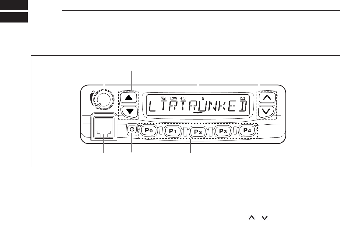
1PANEL DESCRIPTION
uMicrophone
connector
yPower switch tProgrammable keys [P0] to [P4]
rRight
UP/DOWN keys
eFunction display
wLeft
UP/DOWN keys
qAF volume
control knob
■Front panel
qAF VOLUME CONTROL KNOB
Turn the knob to adjust the audio output level.
• Minimum audio level is pre-programmed.
wLEFT UP/DOWN [∫∫]/[√√] KEYS
•Push to select the operating channel.
•Can be programmed for one of several functions by your
dealer. (Same as [P0] to [P4] keys)
eFUNCTION DISPLAY
Displays variety of information, such as operating channel
number/names, 5-tone code, DTMF numbers and audible
condition, etc.
NOTE: The above functions depend on pre-setting.
rRIGHT UP/DOWN [ ]/[ ] KEYS
•Push to select the operating channel.
•Can be programmed for one of several functions by your
00 IC-F610EUR.qxd 01.11.28 11:37 AM Page d (1,1)
2
1
PANEL DESCRIPTION
dealer. (Same as [P0] to [P4] keys)
tDEALER-PROGRAMMABLE KEYS [P0] to [P4]
Can each be programmed for one of several functions by
your Icom dealer.
yPOWER SWITCH
Push to turns the power ON and OFF.
• The following functions are available at power ON as options:
•Automatic scan start
•Password prompt
•Set mode
uMICROPHONE CONNECTOR
Connect the supplied microphone or optional DTMF micro-
phone for SmarTrunk II™operation here.
NEVER connect other microphones. The pin assignments
may be different and the transceiver may be damaged.
MICROPHONE
The supplied microphone has a PTT switch and a hanger
hook.
• The following functions are available when the microphone is on or
off hook:
- Automatic scan start when hung on.
- Automatic priority channel selection when hung off.
- Sets to ‘Inaudible’condition (mute condition) when hung on.
- Sets to ‘Audible’condition (un-mute condition) when off.
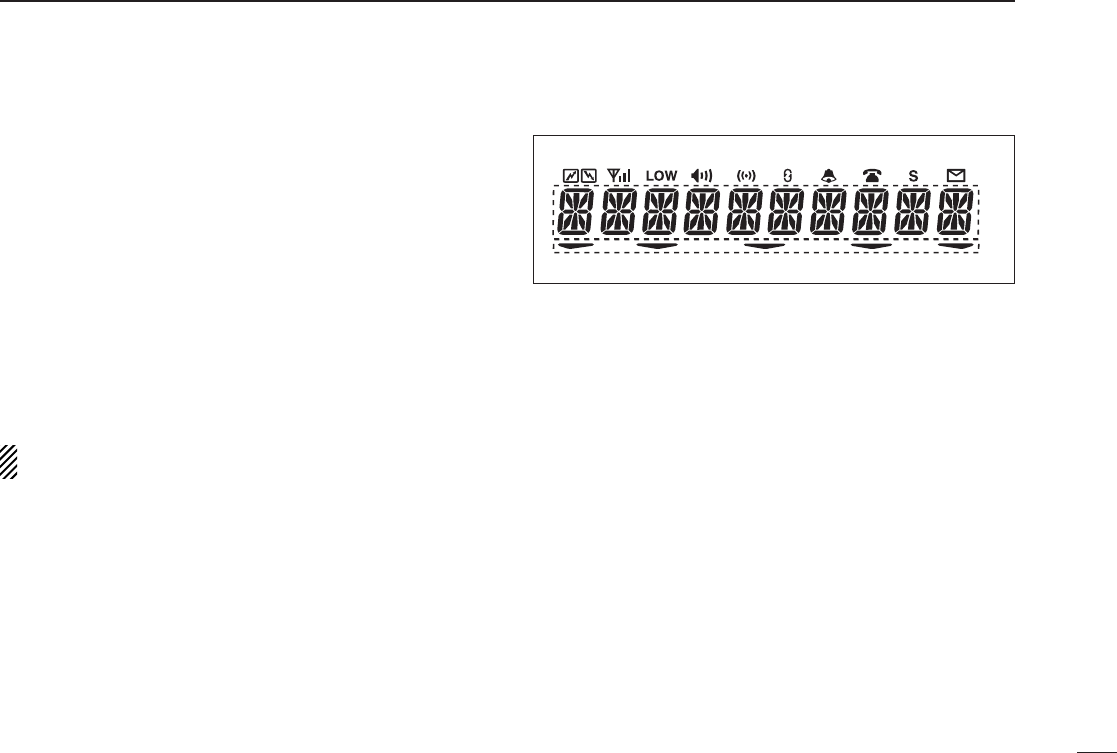
■Function display
qTRANSMIT INDICATOR
•Appears while transmitting or sending a 5-tone code.
•When internal temperature increases to a specific level, the
transmit indicator blinks to indicate that the power down cir-
cuit has been activated.
wBUSY INDICATOR
Appears while the channel is busy.
eSIGNAL STRENGTH METER
Indicates relative signal strength level.
rLOW POWER INDICATOR
Appears when low output power is selected.
tAUDIBLE INDICATOR
Appears when the channel is in the ‘Audible’condition
(unmute condition).
yCOMPANDER INDICATOR
Appears when compander function is activated.
q w e r t y u i o !0 !1
!2
!3
00 IC-F610EUR.qxd 01.11.28 11:37 AM Page e (1,1)

3
1PANEL DESCRIPTION
uSCRAMBLER INDICATOR
Appears when scrambler function is activated. (Optional UT-
109 (#02)/UT110 (#02) SCRAMBLER UNIT is required.)
i2/5TONE INDICATOR
Appears when specified 2/5tone call is received.
o!0 LTR INDICATOR
Appears when LTR function is selected.
!1 SHORT MESSAGE INDICATOR
Appears when a short message is received.
!2 ALPHANUMERIC DISPLAY
Displays the CH number, 5-tone indication, DTMF numbers,
Audible indication, etc.
NOTE: When the alphanumeric display blinks and trans-
mitting becomes impossible. In this case, check that the
antenna is not miss-matched or that DC battery voltage
has not dropped below 8 V
!3 ACTIVATED KEY INDICATOR
Appears or blinks when the key under this indicator is acti-
vated.
■Programmable function keys
The following functions can be assigned to [P0], [P1], [P2],
[P3], [P4], [∫∫], [√√], [ ] and [] programmable function
keys.
Consult your Icom Dealer or System operator for details con-
cerning your transceivers programming.
In the following explanations, programmable function names
are bracketed, the specific switch used to activate the func-
tion depends on programming.
CH UP AND DOWN KEYS
• Select an operating channel.
• Select a transmit code channel after pushing
the [
TX CH
] key.
• Select a DTMF channel after pushing the
[
DTMF
] key.
• Select a scan group after pushing and holding
the [
SCAN
] key.
OPERATING CHANNEL KEYS
Select an operating channel directly.
PRIORITY CHANNEL KEYS
Select priority A or priority B channel with each
push.
[CH UP]
[CH DN]
[CH1]
[CH2]
[CH3]
[CH4]
[PRI A]
00 IC-F610EUR.qxd 01.11.28 11:37 AM Page f (1,1)

4
1
PANEL DESCRIPTION
MONITOR KEY
Activates one of (or two of) the following func-
tions on each channel independently:
• Push and hold the key to unmute the channel (audio
is emitted; ‘Audible’condition).
• Push the key to toggle the mute and unmute condi-
tions (toggles ‘Audible’and ‘Inaudible’).
• Push the key to mute the channel (sets to ‘Inaudible’
only).
• Push the key to unmute the channel (sets to ‘Audible’
only).
• Push the key after the communication is finished to
send a ‘reset code’.
NOTE: The unmute condition (‘Audible’condi-
tion) may automatically return to the mute condi-
tion (‘Inaudible‘ condition) after a specified peri-
od.
WIDE/NARROW KEY
Push [W/N] to toggle bandwidth between wide or
narrow.
•This function is available for W/N versions only.
OUTPUT POWER SELECTION KEYS
Select the transmit output power temporarily or
permanently depending on the pre-setting.
[MONI]
[W/N]
[H/L]
BANK KEY
Select a bank.
• When the optional UT-105 is installed, push one
or more times to select a channel bank for con-
ventional channels or SmarTrunk II™channels.
SCAN START/STOP KEY
Push this key to start scanning; and push again
to stop.
NOTE: Place the microphone on hook to start
scanning.
Take the microphone off hook to stop scanning.
Push and hold this key to indicate the scan
group, then push to select the desired group.
SCAN TAG KEY
Adds or deletes the selected channel to the scan
group.
LOCK KEY
Electronically locks all programmable keys
except the following:
•[
CALL
] (incl. CAL A and CAL B), [
MONI
] and
[
EMER
] keys.
[Bank]
[SCAN A]
[SCAN B]
[TAG]
[LOCK]
00 IC-F610EUR.qxd 01.11.28 11:37 AM Page g (1,1)

5
1PANEL DESCRIPTION
• Ask your Dealer or System Operator for the out-
put power level for each selection.
TALK AROUND KEY
Turns the talk around function ON and OFF.
• The talk around function equalises the transmit
frequency to the receive frequency for mobile-
to-mobile communication.
CALL KEYS
Transmit a 5-tone call.
• Call transmission is necessary before you call
another station depending on your signaling
system.
• The [CAL A] and/or [CAL B] keys may be avail-
able when your system employs selective
‘Individual/Group’calls. Ask your System
Operator which call is assigned to each key.
EMERGENCY KEY
Push and hold the key to transmit an emergency call.
• If you want to cancel the emergency call, push
(or push and hold) the key again before trans-
mitting the call.
• The emergency call is transmitted one time only
or repeatedly until receiving a control code
depending on the pre-setting.
[ TA ]
[CALL]
[CAL A]
[CAL B]
[EMER]
TX CODE KEY
Select a transmit 5-tone code (station code)
channel.
TX CODE CHANNEL UP/DOWN KEY
Push to selects a TX code channel directory.
DTMF CHANNEL SELECT KEY
Push this key to select a DTMF channel.
• Push this key, then select the desired DTMF
channel using the []/[]keys.
Push and hold this key to transmit the selected
DTMF code.
NOTE (LMR ONLY):DTMF channels 7 (EMER-
GENCY) and 8 (LOG/ID) are used for ID code
and emergency code respectively, depending on
your system set up.
Ask your System Operator or Dealer about
DTMF channels 7 and 8 before using these.
C. TONE CHANNEL ENTER KEY
Push this key then input a continuous tone mem-
ory channel number via the keypad to change the
tone frequency.
[TX CH]
[CODE]
[DTMF]
[TONE]
00 IC-F610EUR.qxd 01.11.28 11:37 AM Page h (1,1)

6
1
PANEL DESCRIPTION
ID MEMORY READ KEY
Recalls detected ID codes.
• Push this key, then push []/[]for selec-
tion.
• Up to 5 ID's are memorized.
Push and hold this key to erase all memorized
IDs.
TRUNKING GROUP KEY
Push to select the Trunking group.
MIC COMPANDER KEY
Push to toggle the mic compander function ON
or OFF.
SET MODE KEY
Changes the contents of the items in the User
Set mode.
•Push and hold [SET], push [CH UP]/[CH DN] key
to change the contents.
[ID MR]
[GRP]
[COMP]
[SET]
SCRAMBLER KEY
• Push and hold to turn the voice scrambler func-
tion ON.
• Push to turn the voice scrambler function OFF.
NOTE:
• Optional UT-109 (#02) or UT-110 (#02) VOICE
SCRAMBLER UNIT is required.
-UT-109: Non-rolling type. 32 code numbers are
available.
-UT-110: Rolling type. Provides higher communica-
tion security. 1020 (4 groups x 255) code numbers
are available.
• This transceiver requires version #02 scram-
bler units, do not install version #01, as they are
not compatible.
• UT-109 and UT-110 require some PC board
modifications. Please refer to the additional
installation manual.
•Please contact your dealer for details.
[SCRM]
00 IC-F610EUR.qxd 01.11.28 11:37 AM Page i (1,1)

7
2OPERATION
■Turning power ON
qPush [K
I] to turn the power ON.
• A power-up alert tone sounds for about 1 sec. and an opening
message may appear.
wIf the transceiver is programmed for a start up passcode,
input digit codes as directed by your System operator.
• The keys in the diagram below can be used for password input:
• The transceiver detects numbers in the same block as identical.
Therefore “01234” and “56789” are the same.
eWhen the “PASSWORD” indication does not clear after
inputting 4 digits, the input code number may be incorrect.
Turn power off and start over in this case.
■Channel selection
Several types are available, and the channel selection
method may differ according to your system set up.
NON-BANK TYPE:
Push the [CH Up]/[CH Down] keys to select the desired oper-
ating channel, in sequence; or,
push one of the [CH 1] to [CH 4] keys to select these channels
directly.
BANK-TYPE:
Push [BANK] to select the desired bank number.
AUTOMATIC SCAN TYPE:
Channel setting is not necessary for this type. When turning
the power ON, the transceiver automatically starts scanning.
Scanning stops when receiving a call or when taking the
microphone off hook.
KEY [P0] [P1] [P2] [P3] [P4]
NUMBER01234
56789
00 IC-F610EUR.qxd 01.11.28 11:37 AM Page j (1,1)

8
2
OPERATION
■Receiving and transmitting
RECEIVING:
qPush [K
I] to turn the power ON.
wPush [CH UP] or [CH DN] to select a channel.
eWhen receiving a call, adjust the audio output level to a
comfortable listening level.
TRANSMITTING:
rTake the microphone off hook.
• 5-tone mute may be released (the ‘audible’condition is selected
and “” appears).
• A priority channel may be selected automatically.
tWait for the channel to become clear.
• The channel is busy when “” appears.
yPush the [CALL] key when initiating a call from your side.
• Coded audio may be heard from the transceiver, then “”
appears.
• This operation may not be necessary depending on your signal-
ing system. Ask your System Operator or Dealer.
uWhile pushing and holding [PTT], speak into the micro-
phone at your normal voice level.
iRelease [PTT] to receive.
IMPORTANT: To maximize the readability of your signal: (1)
pause briefly after pushing [PTT], (2) hold the transceiver 15
to 20 cm from your mouth, then speak into the microphone at
a normal voice level.
DTransmitting notes
• Transmit inhibit function
The transceiver has several lockout/inhibit functions which
restrict transmission under the following conditions:
• The channel is in mute condition (‘Inaudible’condition; “”
does not appear).
• Channel is busy.
• No matched (or matched) CTCSS is received.
• The selected channel is a ‘receive only’channel.
• Time-out timer
After continuous transmission for a pre-programmed period,
the time-out timer is activated causing the transceiver to stop
transmitting and automatically select receive.
• Penalty timer
Once the time-out timer is activated, transmission is further
inhibited for a period determined by the penalty timer.
00 IC-F610EUR.qxd 01.11.28 11:37 AM Page k (1,1)

9
2OPERATION
DTx code channel selection
If the transceiver has a [
TX CH
] key, display can be toggled
between the operating channel number (or name) and Tx
code channel number (or name). When the Tx code channel
number (or name) is displayed, the [CH UP]/[CH DN] keys
select the Tx code channel.
TO SELECT A TX CHANNEL:
qPush [
TX CH
] — a Tx code channel appears.
wPush [CH UP]/[CH DN] to select the desired Tx code chan-
nel.
ePush [
CALL
] to transmit the selected Tx code.
rPush [
TX CH
] again to return to the channel display.
DTx code number selection
If the transceiver has a [
CODE
] key, Tx code contents can be
changed within the allowable digits.
TO SELECT A TX CODE:
qPush [
CODE
] — a Tx code number appears and an allow-
able digit blinks.
wPush [CH UP]/[CH DN] to select the desired number at the
blinking digit.
ePush [
CODE
] to enter the selected number.
rRepeat steps wand eto input all allowed digits.
tPush [
CALL
] to transmit the selected Tx code.
DDTMF transmission
If the transceiver has a [
DTMF
] key, the automatic DTMF
transmission function is available. Up to 7 DTMF channels
may be available.
qPush [
DTMF
] to select the display as at right.
wPush [CH UP]/[CH DN] to select the desired DTMF channel.
ePush and hold [
DTMF
] to transmit the DTMF code on the
selected DTMF channel.
DScrambler function
A UT-109 (#02) or UT-110 (#02) optional voice scrambler unit
provides high performance private communication between
stations with the same scrambler codes.
qPush and hold [SCRM] to turn the scrambler function ON.
wPush [SCRM] to turn the function OFF.
00 IC-F610EUR.qxd 01.11.28 11:37 AM Page l (1,1)

10
2
OPERATION
DUser set mode
User set mode is accessed at power ON and allows you to
set seldom-changed settings. in this case you can “cus-
tomize” transceiver operation to suit your preferences and
operating style.
Entering the user set mode:
qWhile pushing and holding []and [], push [K
I] to turn
the user set mode ON, allowing you to set seldom-changed
settings.
wPush [P 0] to select the appropriate item. Then push []
and [] to set the desired level/mode.
Available set mode functions:
•SQL Level; 0 to 255
• Audio Filter; 3000, 3400, 0 or 300
•Beep Level; 1 to 5 or Link (links to audio output level)
•Back Light; AUTO, DIM, OFF or ON
•AF Min level; 0 to 255
•Mic Gain; 1 to 5
•Beep; ON or OFF
ePush [K
I] again to exit set mode.
00 IC-F610EUR.qxd 01.11.28 11:37 AM Page m (1,1)

11
3OPTIONAL SmarTrunk II™ OPERATION
■SmarTrunk II™ and
conventional modes
This transceiver is capable of SmarTrunk II™functions.
The optional UT-105 allows communication in conventional
channels or SmarTrunk II™channels. Select a channel bank
for SmarTrunk II™before trunking operation.
•Push [BANK] one or more times to select a channel bank for
conventional channels or SmarTrunk II™channels.
- Scanning starts when a channel bank for SmarTrunk II™is select-
ed.
- Contact your Dealer for channel bank details.
NOTE: Connect an optional HM-100TN DTMF MICRO-
PHONE. Contact your Dealer for details.
■SmarTrunk II™ operation
These features are enabled by a Dealer or System Operator
and may not be available in your system. Contact your Dealer
for details.
DPlacing a telephone call
Enter the phone number followed by [1], [M].
• A high-pitched beep indicates that the number is accepted.
• When the called party answers, push the [PTT] switch to talk, and
release it to listen.
DCalling another local system subscriber
Enter the subscriber number followed by [3], [M].
• A high-pitched beep indicates that the number is accepted.
• You hear ringing, then two short beeps when the subscriber
answers.
• If the other subscriber is on another call or out of range, you hear a
fast busy signal and the call terminates automatically.
DReceiving a call
When you hear ringing, push [M] to answer.
• For a group call, you hear a short ring followed by two short beeps.
You do not have to answer a group call to hear it over the air.
00 IC-F610EUR.qxd 01.11.28 11:37 AM Page n (1,1)

12
3
OPTIONAL SmarTrunk II™OPERATION
DTerminating a call
After completing a call, push [#] to disconnect (hang up).
IMPORTANT: If one person in the conversation terminates
a call, all participants will be cut off.
DLast number re-dial
Push [M], [M] to automatically re-dial the last number called.
• A high-pitched beep indicates that the number is accepted.
DMemory speed-dialling
To automatically dial a commonly used number from memory:
•Push [M] followed by the memory location (0–9).
DTurbo SpeeDial
To automatically dial a commonly used number with one
push:
•Push one of the turbo SpeeDials ([A], [B], [C] or [D]).
DProgramming memory speed dial
qPush and hold [M] until you hear a high-pitched beep.
wEnter the memory location (0–9, A, B, C, D), the telephone
or subscriber number, then [1], [M] (or [3], [M] if for another
system subscriber).
• A high-pitched beep indicates successful programming.
• Memories [A]–[D] are used for the Turbo SpeeDial.
DSystem busy indication
If all channels are busy, three low beeps sound after you initi-
ate a call. Try the call again later.
DPTT dispatch operation
qPush [PTT] once (without dialling) to initiate a dispatch call.
wBegin talking after you hear three beeps (one short, high-
pitched, two very-short, low-pitched).
eReceiving a dispatch call is indicated by the same three-
beep sequence.
• It is not necessary to push [M] to answer a dispatch call.
DEmergency call
Push [0], [M] to initiate an emergency call.
• Contact your dealer for details.
DClear channel alerting
If all channels are busy, the transceiver automatically begins
searching for an open channel and beeps every ten seconds.
When two short beeps (low-pitched, then high-pitched) are
heard, a channel is available. Push [M], [M] immediately to re-
dial the last number.
NOTE: For additional operating instructions, contact your
Dealer or System Operator.
00 IC-F610EUR.qxd 01.11.28 11:37 AM Page o (1,1)
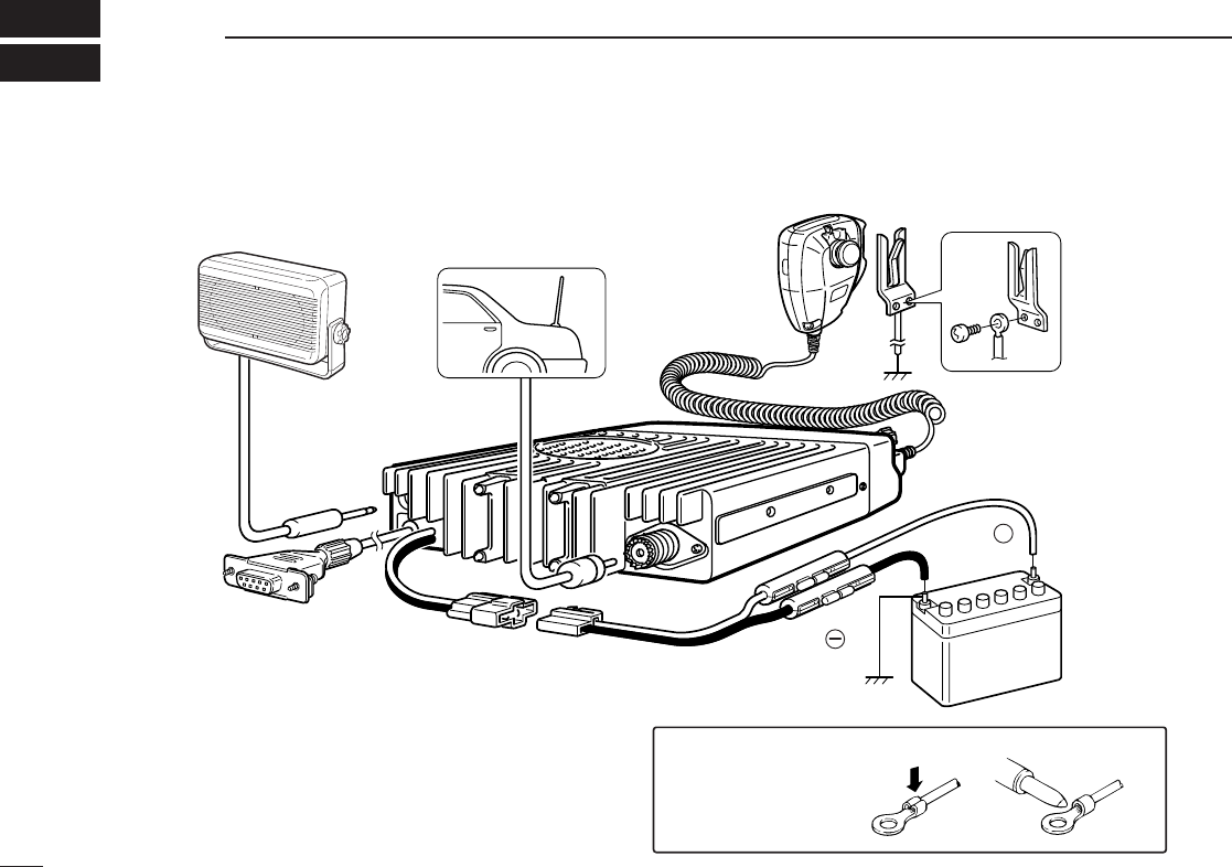
13
4CONNECTION AND MAINTENANCE
NEVER connect to
a 24 V battery.
Solder
Crimp
Note: Use the
terminals for the
cable connections.
+
q˚Antenna
Optional speaker
(SP-22)
r˚
t˚Optional cable
(OPC-617) e˚Supplied DC
power cable
w
12V
Battery
red:
black:
■Rear panel and connection
00 IC-F610EUR.qxd 01.11.28 11:37 AM Page p (1,1)
14
4
CONNECTION AND MAINTENANCE
⁄ANTENNA CONNECTOR
Connects to an antenna. Ask your Dealer about antenna
selection and placement.
¤MICROPHONE HANGER
Connect the supplied microphone hanger to the vehicle’s
ground for on/off hook microphone functions. (See p. 2)
‹DC POWER RECEPTACLE
Connects to a 12 V DC battery. Pay attention to polari-
ties. NEVER connect to a 24 V battery. This could dam-
age the transceiver.
›EXTERNAL SPEAKER JACK
Connect a 4–8 Ωexternal speaker, if desired.
fiOPTIONAL CABLE (OPC-617)
Connect an external modem unit, LCD backlight control,
etc.
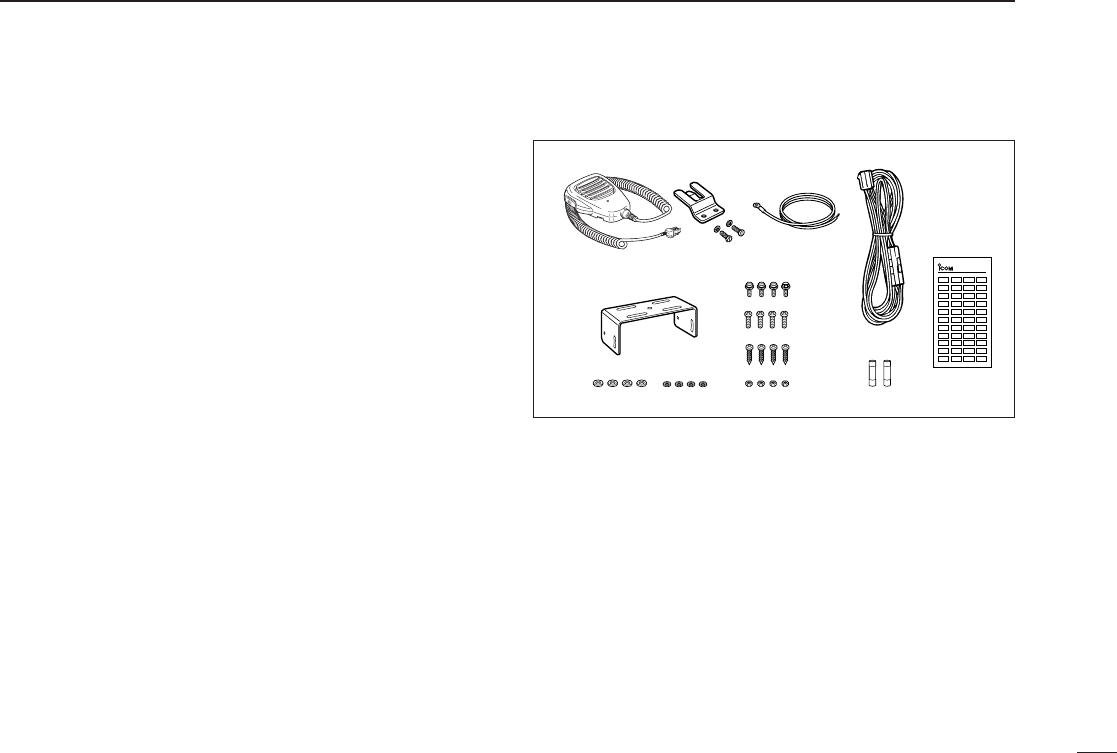
■Supplied Accessories
qMicrophone ...................... 1
(Some versions may not be sup-
plied with a microphone)
wMicrophone hanger and
screw set ..................... 1 set
eMicrophone hanger cable . 1
rDC power cable .................1
IC-F510/F610: OPC-345
IC-F520/F620: OPC-346
tMounting bracket .............. 1
yBracket bolt ....................... 4
uMounting screw (M5×12) ... 4
iSelf-tapping screw
(M5×20) ............................. 4
oFlat washer ....................... 4
!0 Spring washer ................... 4
!1 Nut .................................... 4
!2 Fuse ................................. 2
IC-F510/F610: 15 A
IC-F520/F620: 20 A
!3 Function name stickers*
(1705 LCD SEAL(D)) .............1
D*Function name stickers
There are no names on the programmable function keys since the
needed functions can be assigned to these keys.
Attach the supplied function name stickers above the appropriate
keys.
12
3
4
56
7
8
90 A B C
LCD-STICKER
ICOM
00 IC-F610EUR.qxd 01.11.28 11:37 AM Page q (1,1)
15
4CONNECTION AND MAINTENANCE
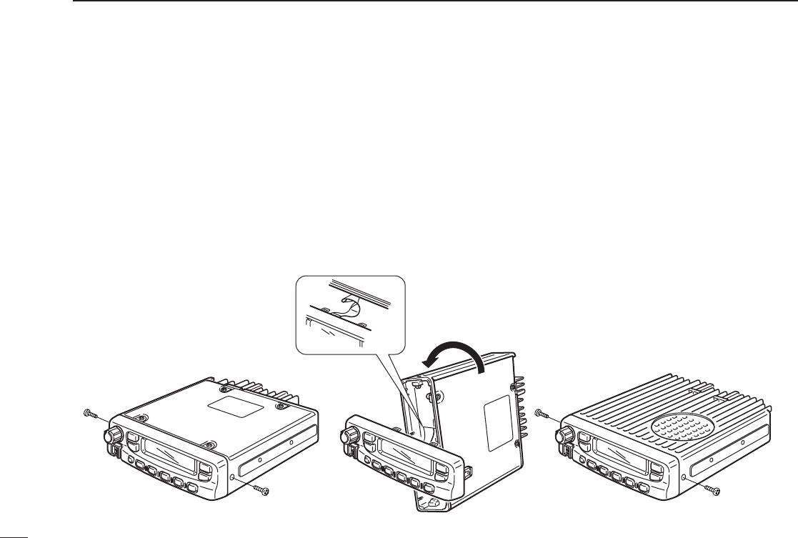
■Mounting the transceiver
The front panel can be inverted for correct viewing while leav-
ing the built-in speaker facing away from the mounting surface.
DInverting the Front panel
qUnscrew the 2-side screws.
wRemove the Front panel forward from the transceiver.
eInvert the transceiver 180°clockwise as below.
rInsert the Front panel to the transceiver.
tTight the 2 screws.
NOTE:
•NEVER rotate the transceiver more than 180°.
•DO NOT spread the flat cable too much on the transceiver.
Damage may occur.
00 IC-F610EUR.qxd 01.11.28 11:37 AM Page r (1,1)
16
4
CONNECTION AND MAINTENANCE
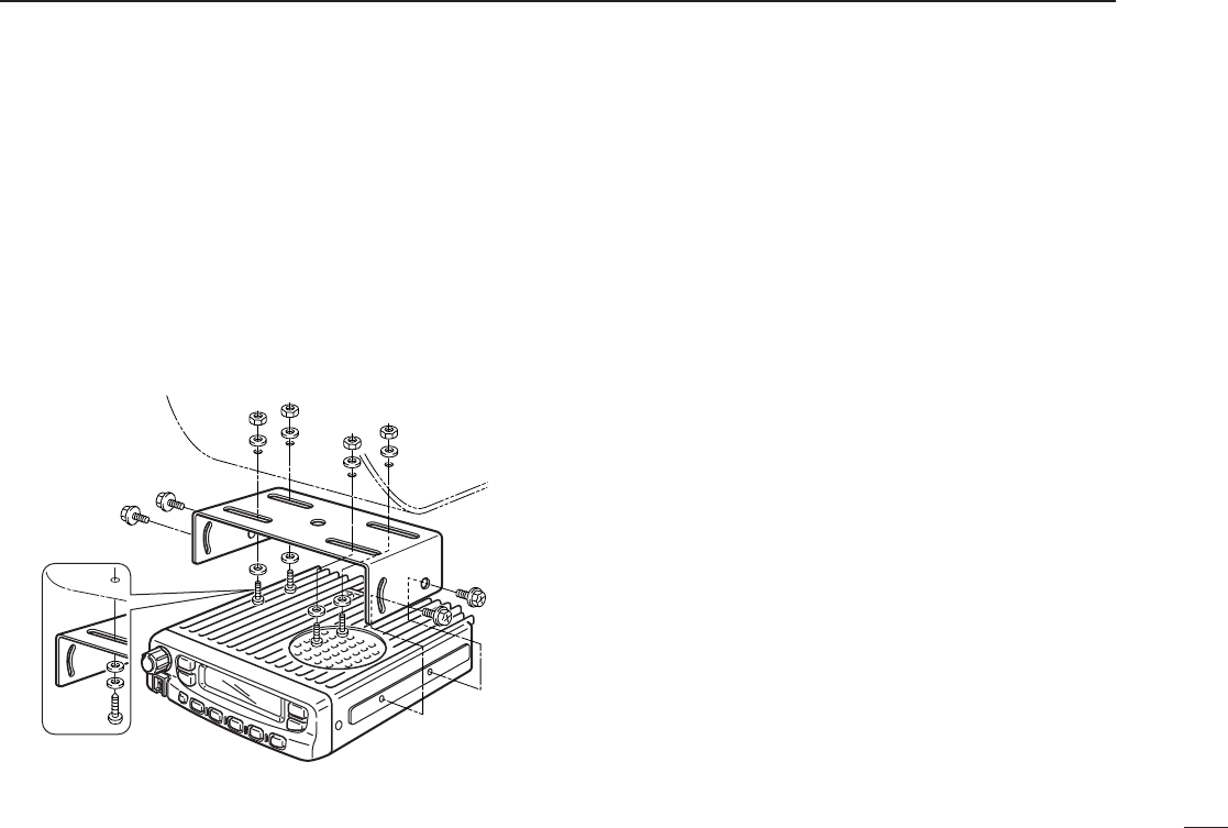
DMounting the transceiver
The universal mounting bracket supplied with your transceiv-
er allows overhead mounting. Please read the following
instructions carefully.
•Mount the transceiver securely with the 4 supplied screws
to a thick surface which can support more than 1.5 Kg.
Flat washer
Spring washer
When using
self-tapping screws
00 IC-F610EUR.qxd 01.11.28 11:37 AM Page s (1,1)
17
4CONNECTION AND MAINTENANCE
■Optional UT-105 and UT-108
installation
The optional UT-105 and UT-108 units install as follows:
qTurn power OFF, then disconnect the DC power cable.
wUnscrew the 4 screws, then remove the bottom cover.
eInstall the unit as shown in the diagram below.
rReplace the bottom cover and screws, then the DC power
cable.
NOTE: The sponge supplied with the UT-105 is for the IC-F30/F40
series transceivers only.
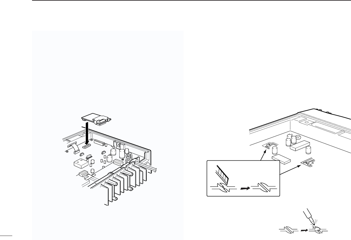
■Optional UT-109 /UT-110 in-
stallation
qTurn power OFF, then disconnect the DC power cable.
wUnscrew the 4 screws, then remove the bottom cover.
eCut the print pattern on the PC board at the TX mic circuit
(A) and RX AF circuit (B) as shown in the following figure.
rInstall the Scrambler unit as shown in the left.
tReplace the bottom cover and screws, then the DC power
cable.
NOTE: Be sure to resolder above
disconnected points, otherwise
no TX modulation or AF output is
available when you remove the
scrambler units.
A
B
00 IC-F610EUR.qxd 01.11.28 11:37 AM Page t (1,1)
18
4
CONNECTION AND MAINTENANCE
■Antenna
A key element in the performance of any communication sys-
tem is an antenna. Ask your Dealer about antennas and the
best places to mount them.
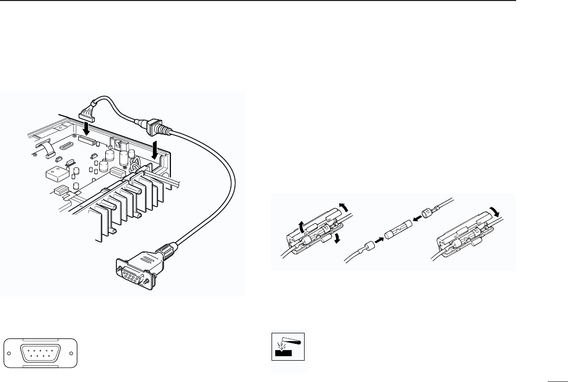
■Fuse replacement
Two fuses are installed in the supplied DC power cable. If a
fuse blows or the transceiver stops functioning, track down
the source of the problem, if possible, and replace the dam-
aged fuse with a new, rated one.
❑Fuse rating IC-F510/F610: 15 A, IC-F520/F620: 20 A
■Cleaning
If the transceiver becomes dusty or dirty, wipe it clean with a
dry, soft cloth.
AVOID the use of solvents such as benzene or alco-
hol, as they may damage transceiver surfaces.
q
LCD backlit cont. IN
wAF OUT
eDet. AF OUT
rMod. IN
tPTT control IN
yHorn drive cont. OUT
uAF GND
iDet. AF GND
oMod. GND
OPTIONAL CABLE PIN ASSIGNMENT
t r e w q
o i u y
■Optional OPC-617
installation
00 IC-F610EUR.qxd 01.11.28 11:37 AM Page u (1,1)

19
5OPTIONS
SP-22
Compact and easy-to-install
Input impedance: 4 Ω
Max. input power: 5 W
HM-100TN
DTMF microphone.
SM-25
Normal microphone.
UT-105 SmarTrunk II™Logic Board
Provides SmarTrunk II™capabilities.
UT-108 DTMF DECODER UNIT
Provides pager and code squelch capabilities.
UT-109/UT-110 VOICE SCRAMBLER UNIT
• UT-109: Non-rolling type (max. 32 codes)
• UT-110: Rolling type (max. 1020 codes)
OPC-617 ACC CABLE
Allows you to connect to an external terminal.
00 IC-F610EUR.qxd 01.11.28 11:37 AM Page v (1,1)

Count on us!
1-1-32 Kamiminami, Hirano-ku, Osaka 547-0003 Japan
A-6120H-1EX
Printed in Japan
© 2001 Icom Inc.