ICOM orporated IC-F621-2 IC-F621-2 User Manual IC F510F520 F610F620
ICOM Incorporated IC-F621-2 IC F510F520 F610F620
Contents
- 1. Pages 1 to 8 of the Users Manual
- 2. Pages 9 to 16 of the Users Manual
- 3. Pages 17 to 24 of the Users Manual
Pages 1 to 8 of the Users Manual

i
EXPLICIT DEFINITIONS
RWARNING! NEVER connect the transceiver to an
AC outlet. This may pose a fire hazard or result in an electric
shock.
NEVER connect the transceiver to a power source of more
than 16 V DC such as a 24 V battery. This connection will ruin
the transceiver.
NEVER cut the DC power cable between the DC plug and
fuse holder. If an incorrect connection is made after cutting,
the transceiver might be damaged.
NEVER place the transceiver where normal operation of
the vehicle may be hindered or where it could cause bodily
injury.
NEVER allow children to touch the transceiver.
NEVER expose the transceiver to rain, snow or any liquids.
USE supplied microphone only. Other microphones have
different pin assignments and may damage the transceiver.
DO NOT use or place the transceiver in areas with tem-
CAUTIONS
WORD DEFINITION
RWARNING Personal injury, fire hazard or electric shock
may occur.
CAUTION Equipment damage may occur.
NOTE If disregarded, inconvenience only. No risk
of personal injury, fire or electric shock.
READ ALL INSTRUCTIONS carefully and complete-
ly before using the transceiver.
SAVE THIS INSTRUCTION MANUAL— This
instruction manual contains important operating instructions for
the IC-F521 VHF TRANSCEIVERand
IC-F621 UHF TRANSCEIVER.
IMPORTANT
IC-F510F520_F610F620.qxd 02.1.21 10:03 AM Page b (1,1)

ii
peratures below –22°F (–30°C) or above +140°F (+60°C) or,
in areas subject to direct sunlight, such as the dashboard.
AVOID operating the transceiver without running the vehi-
cle’s engine. The vehicle’s battery will quickly run out if the
transceiver is in transmission while the vehicle’s engine OFF.
AVOID placing the transceiver in excessively dusty envi-
ronments.
AVOID placing the transceiver against walls. This will
obstruct heat dissipation.
AVOID the use of chemical agents such as benzine or
alcohol when cleaning, as they damage the transceiver sur-
faces.
BE CAREFUL! The transceiver will become hot when
operating continuously for long periods.
For U.S.A. only
CAUTION: Changes or modifications to this transceiver, not
expressly approved by Icom Inc., could void your authority to
operate this transceiver under FCC regulations.
TABLE OF CONTENTS
IMPORTANT .................................................................................... i
EXPLICIT DEFINITIONS ................................................................. i
CAUTIONS ....................................................................................... i
TABLE OF CONTENTS .................................................................. ii
1 PANEL DESCRIPTION ........................................................ 1–6
■Front panel ............................................................................ 1
■Function display .................................................................... 2
■Programmable function keys ................................................ 3
2 OPERATION ...................................................................... 7–10
■Turning power ON ................................................................ 7
■Channel selection ................................................................. 7
■Receiving and transmitting ................................................... 8
DTransmitting notes .......................................................... 8
DTx code channel selection .............................................. 9
DTx code number selection .............................................. 9
DDTMF transmission ........................................................ 9
DScrambler function ......................................................... 9
DUser set mode .............................................................. 10
3 OPTIONAL SmarTrunk II™ OPERATION ....................... 11–12
■SmarTrunk II™ and conventional modes ............................ 11
■SmarTrunk II™ operation .................................................... 11
4 CONNECTION AND MAINTENANCE ............................. 13–18
■Rear panel and connection ................................................. 13
■Supplied Accessories ......................................................... 14
■Mounting the transceiver ..................................................... 15
DInverting the Front panel .............................................. 15
DMounting the Transceiver ............................................. 16
■Optional UT-105/UT-108 installation ................................... 17
■Optional UT-109/UT-110 installation ................................... 17
■Optional OPC-617 installation ............................................. 18
■Antenna ............................................................................... 18
■Fuse replacement ............................................................... 18
■Cleaning ............................................................................. 18
5 OPTIONS ............................................................................... 19
IC-F510F520_F610F620.qxd 02.1.21 10:03 AM Page c (1,1)
1
1PANEL DESCRIPTION
uyt
r
e
w
q
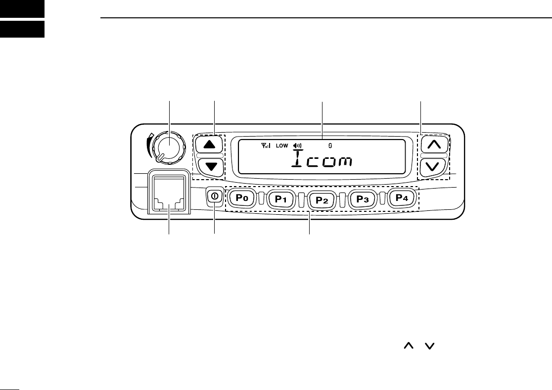
■Front panel
qAF VOLUME CONTROL KNOB
➥Rotate the knob to adjust the audio output level.
• Minimum audio level is pre-programmed.
wLEFT UP/DOWN [∫∫]/[√√] KEYS
➥One of several functions can be programmed by your
Dealer. (Same as [P0] to [P4] keys)
eFUNCTION DISPLAY
➥Displays variety of information, such as an operating chan-
nel number/name, 2/5tone code, DTMF numbers and audi-
ble condition, etc.
NOTE: The above functions depend on pre-programming.
rRIGHT UP/DOWN [ ]/[ ] KEYS
➥Push to select the operating channel.
➥Can be programmed for one of several functions by your
Dealer. (Same as [P0] to [P4] keys)
IC-F510F520_F610F620.qxd 02.1.21 10:03 AM Page d (1,1)
2
1
PANEL DESCRIPTION
tDEALER-PROGRAMMABLE KEYS [P0] to [P4]
➥Desired functions can be programmed independently by
your Dealer.
yPOWER SWITCH [POWER]
➥Push to turns the power ON and OFF.
• The following functions are available at power ON as options:
-Automatic scan start
-Password prompt
-Set mode
uMICROPHONE CONNECTOR
➥Connect the supplied microphone or optional DTMF micro-
phone for SmarTrunk II™ operation here.
NEVER connect non-specified microphones. The pin
assignments may be different and the transceiver may be
damaged.
MICROPHONE
➥The supplied microphone has a PTT switch and a hanger
hook.
• The following functions are available when the microphone is on
or off hook:
-Automatic scan start when hung on.
- Automatic priority channel selection when hung off.
- Sets to ‘Inaudible’ condition (mute condition) when hung on.
- Sets to ‘Audible’ condition (un-mute condition) when hung off.
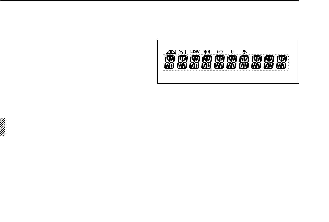
■Function display
qTRANSMIT INDICATOR
➥Appears while transmitting or sending a 2/5tone code.
wBUSY INDICATOR
➥Appears while the channel is in busy.
eSIGNAL STRENGTH METER
➥Indicates relative signal strength level.
rLOW POWER INDICATOR
➥Appears when low output power is selected.
tAUDIBLE INDICATOR
➥Appears when the channel is in the ‘Audible’ condition
(unmute condition).
yCOMPANDER INDICATOR
➥Appears when compander function is activated.
q w e r t y u i
o
IC-F510F520_F610F620.qxd 02.1.21 10:03 AM Page e (1,1)

3
1PANEL DESCRIPTION
uSCRAMBLER INDICATOR
➥Appears when scrambler function is activated. (Optional UT-
109 (#02)/UT110 (#02) SCRAMBLER UNIT is required.)
i2/5TONE INDICATOR
➥Appears when specified 2/5tone call is received.
oALPHANUMERIC DISPLAY
➥Displays the CH number, 2/5tone indication, DTMF num-
bers, Audible indication, etc.
■Programmable function keys
The following functions can be assigned to [P0], [P1], [P2],
[P3], [P4], [∫∫], [√√], [ ] and [] programmable function
keys.
Consult your Icom Dealer or System operator for details con-
cerning your transceivers programming.
In the following explanations, programmable function names
are bracketed, the specific switch used to activate the func-
tion depends on programming.
CH UP AND DOWN KEYS
• Select an operating channel.
• Select a transmit code channel after pushing
the [
TX CH
] key.
• Select a DTMF channel after pushing the
[
DTMF
] key.
• Select a scan group wile pushing and holding
the [
SCAN
] key.
OPERATING CHANNEL KEYS
Select an operating channel directly.
PRIORITY CHANNEL KEYS
Select priority A or priority B channel with each
push.
[CH UP]
[CH DN]
[CH1]
[CH2]
[CH3]
[CH4]
[PRI A]
[PRI B]
IC-F510F520_F610F620.qxd 02.1.21 10:03 AM Page f (1,1)

4
1
PANEL DESCRIPTION
MONITOR KEY
Activates one of (or two of) the following func-
tions on each channel independently:
• Push and hold the key to unmute the channel (audio
is emitted; ‘Audible’ condition).
• Push the key to toggle the mute and unmute condi-
tions (toggles ‘Audible’ and ‘Inaudible’).
• Push the key to mute the channel (sets to ‘Inaudible’
only).
• Push the key to unmute the channel (sets to ‘Audible’
only).
• Push the key after the communication is finished to
send a ‘reset code’.
NOTE: The unmute condition (‘Audible’ condi-
tion) may automatically return to the mute condi-
tion (‘Inaudible‘ condition) after a specified peri-
od.
WIDE/NARROW KEY
Push [W/N] to toggle bandwidth between wide or
narrow.
OUTPUT POWER SELECTION KEYS
Select the transmit output power temporarily or
permanently depending on the pre-setting.
• Ask your Dealer or System Operator for the out-
put power level for each selection.
[MONI]
[W/N]
[H/L]
BANK KEY
Select and determine a bank number.
• When the optional UT-105 is installed, push [BANK]
then push [CH UP]/[CH DN] to select operating bank
number, and then push [BANK] to determine the
bank number.
SCAN START/STOP KEY
Push this key to start scanning; and push again
to stop.
NOTE: Place the microphone on hook to start
scanning.
Take the microphone off hook to stop scanning.
Push and hold this key to indicate the scan
group, then push to select the desired group.
SCAN TAG KEY
Adds or deletes the selected channel to the scan
group.
LOCK KEY
Electronically locks all programmable keys
except the following:
•[
CALL
](incl. [CAL A] and [CAL B]), [
MONI
]and
[
EMER
]keys.
[BANK]
[SCAN A]
[SCAN B]
[TAG]
[LOCK]
IC-F510F520_F610F620.qxd 02.1.21 10:03 AM Page g (1,1)

5
1PANEL DESCRIPTION
TALK AROUND KEY
Turns the talk around function ON and OFF.
• The talk around function equalises the transmit
frequency to the receive frequency for mobile-
to-mobile communication.
CALL KEYS
Transmit a 5-tone code.
• Call transmission is necessary before you call
another station depending on your signaling
system.
• The [CAL A] and/or [CAL B] keys may be
available when your system employs selective
‘Individual/Group’ calls. Ask your Dealer which
call is assigned to each key.
EMERGENCY KEY
Push and hold the key to transmit an emergency call.
• If you want to cancel the emergency call, push
(or push and hold) the key again before trans-
mitting the call.
• The emergency call is transmitted one time only
or repeatedly until receiving a control code
depending on the pre-setting.
[ T A ]
[CALL]
[CAL A]
[CAL B]
[EMER]
TX CODE KEY
Select a transmit 5-tone code (station code)
channel.
TX CODE CHANNEL UP/DOWN KEY
Push to selects a TX code channel directory.
DTMF CHANNEL SELECT KEY
Push this key to select a DTMF channel.
• Push this key, then select the desired DTMF
channel using the [ ]/[ ] keys.
Push the key to transmit the selected DTMF
code.
C. TONE CHANNEL ENTER KEY
Push this key then input a continuous tone mem-
ory channel number using [ ]/[ ] keys to
change the tone frequency.
[TX CH]
[CODE]
[DTMF]
[TONE]
IC-F510F520_F610F620.qxd 02.1.21 10:03 AM Page h (1,1)