ICOM orporated IC-F621-2 IC-F621-2 User Manual IC F510F520 F610F620
ICOM Incorporated IC-F621-2 IC F510F520 F610F620
Contents
- 1. Pages 1 to 8 of the Users Manual
- 2. Pages 9 to 16 of the Users Manual
- 3. Pages 17 to 24 of the Users Manual
Pages 17 to 24 of the Users Manual
14
4
CONNECTION AND MAINTENANCE
qANTENNA CONNECTOR
Connects to an antenna. Ask your Dealer about antenna
selection and placement.
wMICROPHONE HANGER
Connect the supplied microphone hanger to the vehicle’s
ground for microphone on/off hook functions. (See p. 2)
eDC POWER RECEPTACLE
Connects to a 12 V DC battery. Pay attention to polari-
ties. NEVER connect to a 24 V battery. This could dam-
age the transceiver.
rEXTERNAL SPEAKER JACK
Connect a 4–8 Ωexternal speaker, if desired.
tOPTIONAL CABLE (OPC-617)
Connect an external modem unit, LCD backlight control,
etc.
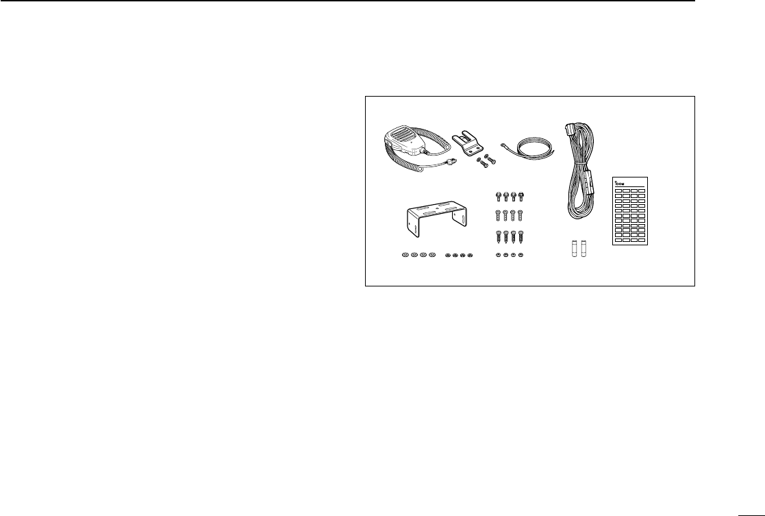
■Supplied Accessories
qMicrophone ...................... 1
wMicrophone hanger and
screw set ..................... 1 set
eMicrophone hanger cable . 1
rDC power cable
(OPC-346)..........................1
tMounting bracket .............. 1
yBracket bolts ..................... 4
uMounting screws (M5×12) . 4
iSelf-tapping screws
(M5×20) ............................. 4
oFlat washers ...................... 4
!0 Spring washers ................. 4
!1 Nuts ................................... 4
!2 Fuse s (20 A) .....................2
!3 Function name stickers*
(1705 LCD SEAL(D)) .............1
*Function name stickers
There are no names on the programmable function keys since the
needed functions can be assigned to these keys.
Attach the supplied function name stickers above the appropriate
keys.
qwer
ty
u
i
o!0 !1 !2 !3
LCD-STICKER
ICOM
IC-F510F520_F610F620.qxd 02.1.21 10:03 AM Page q (1,1)
15
4CONNECTION AND MAINTENANCE
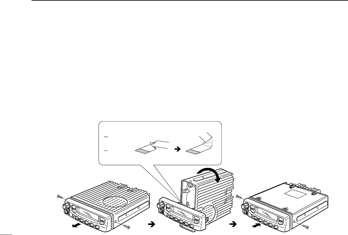
■Mounting the transceiver
The front panel can be inverted for correct viewing while leav-
ing the built-in speaker facing away from the mounting sur-
face.
DInverting the Front panel
qUnscrew the 2-side screws.
wDetach the Front panel forward from the transceiver.
eBend the flat cable between Front panel and main unit as
shown in the following diagram.
rInvert the transceiver 180 degrees clockwise as below.
tRe-attach the Front panel to the transceiver.
yTighten the 2 screws.
CAUTION:
•NEVER rotate the transceiver more than 180 degrees.
•DO NOT bend the flat cable too hard. Damage may occur.
normal bend line
inverted
bend line
Flat cable orientation
to Front panel
to MAIN unit
NOTE: Be sure to bend the flat cable in the
correct direction, before turning
over (inverting) the transceiver.
IC-F510F520_F610F620.qxd 02.1.21 10:03 AM Page r (1,1)
16
4
CONNECTION AND MAINTENANCE
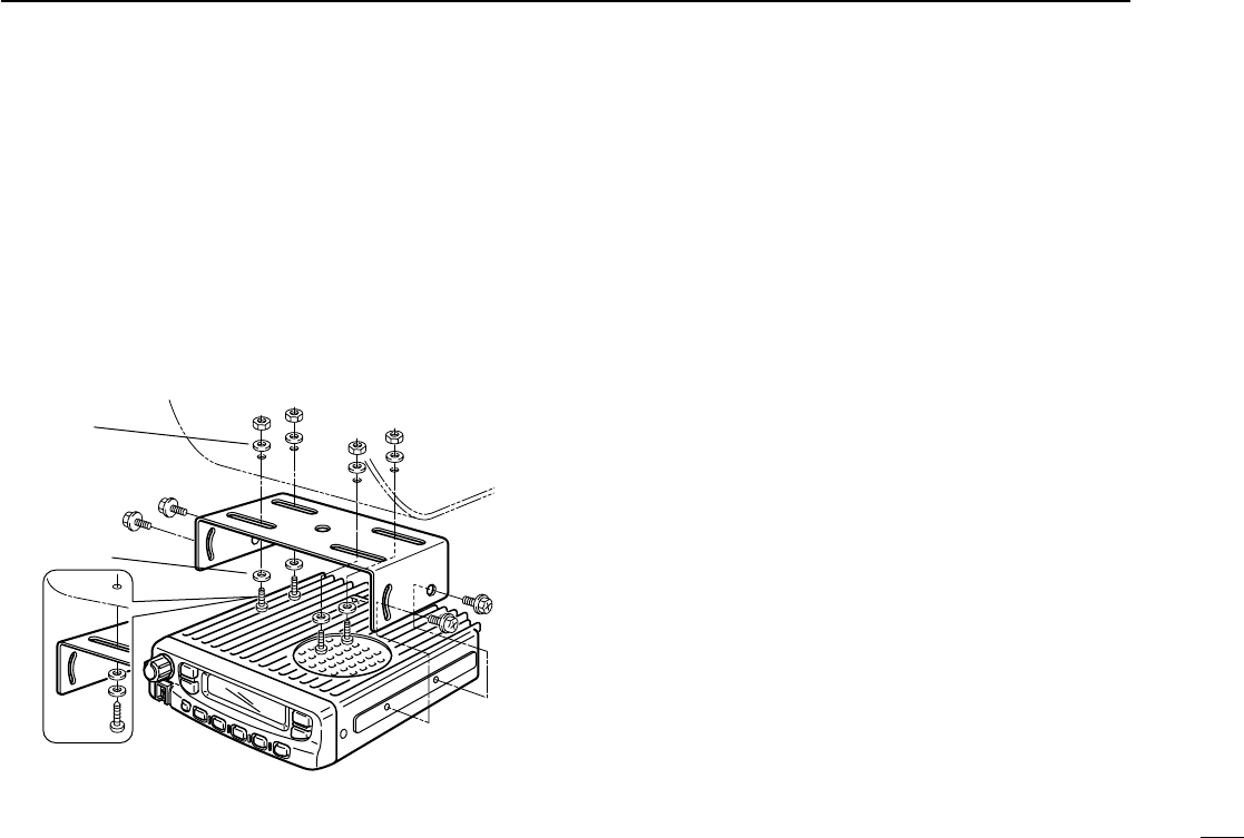
DMounting the transceiver
The universal mounting bracket supplied with your transceiv-
er allows overhead mounting.
•Mount the transceiver securely with the 4 supplied screws
to a thick surface which can support more than 1.5 kg.
Flat washer
Spring washer
When using
self-tapping screws
IC-F510F520_F610F620.qxd 02.1.21 10:03 AM Page s (1,1)
17
4CONNECTION AND MAINTENANCE
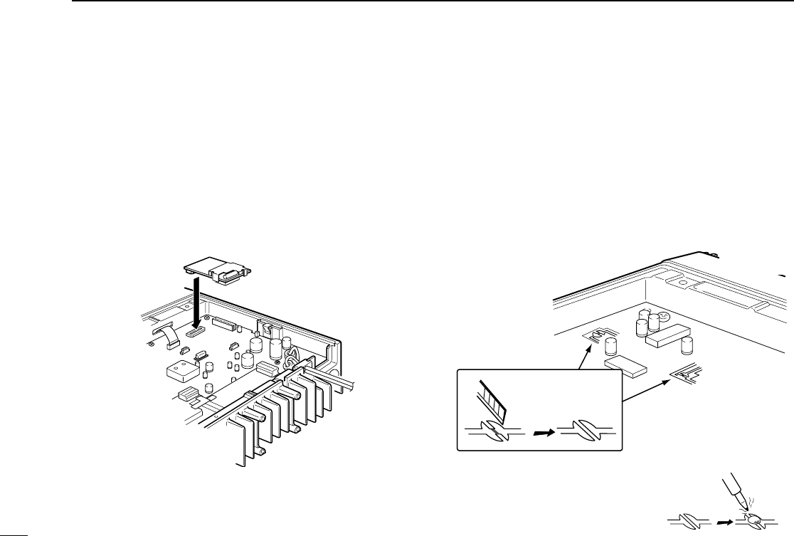
■Optional UT-105 and UT-108
installation
The optional UT-105 and UT-108 units install as follows:
qTurn power OFF, then disconnect the DC power cable.
wUnscrew the 4 screws, then remove the bottom cover.
eInstall the unit as shown in the diagram below.
rReplace the bottom cover and screws, then the DC power
cable.
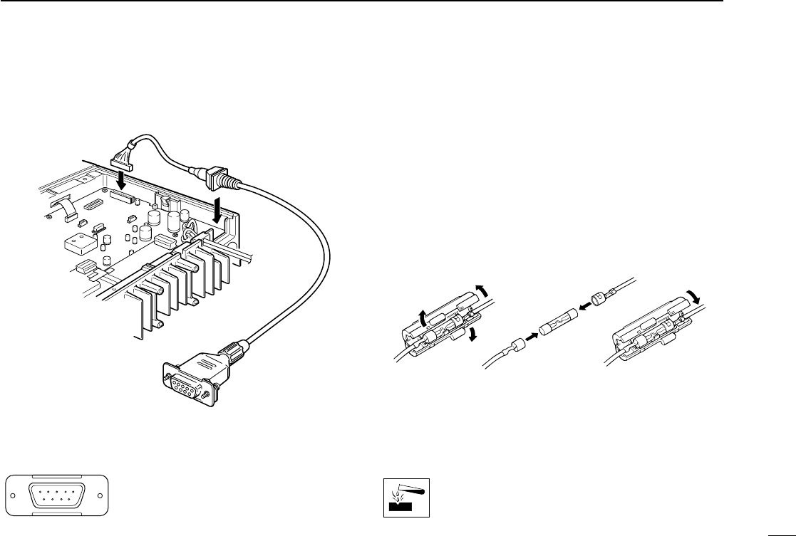
■Optional UT-109 /UT-110
installation
qTurn power OFF, then disconnect the DC power cable.
wUnscrew the 4 screws, then remove the bottom cover.
eCut the print pattern on the PCB at the TX mic circuit (A)
and RX AF circuit (B) as shown in the following figure.
rInstall the scrambler unit as shown in the left.
tReturn the bottom cover and screws to the original posi-
tion.
NOTE: Be sure to re-solder
above disconnected points, oth-
erwise no TX modulation or AF
output is available when you
remove the scrambler units.
A
B
Front panel
IC-F510F520_F610F620.qxd 02.1.21 10:03 AM Page t (1,1)
18
4
CONNECTION AND MAINTENANCE
■Antenna
A key element in the performance of any communication sys-
tem is an antenna. Ask your Dealer about antennas and the
best places to mount them.
■Fuse replacement
Two fuses are installed in the supplied DC power cable. If a
fuse blows or the transceiver stops functioning, track down
the source of the problem, if possible, and replace the dam-
aged fuse with a new rated one.
❑Fuse rating : 15 A,
■Cleaning
If the transceiver becomes dusty or dirty, wipe it clean with a
dry, soft cloth.
AVOID the use of solvents such as benzene or alco-
hol, as they may damage transceiver surfaces.
q
LCD backlit cont. IN
wAF OUT
eDet. AF OUT
rMod. IN
tPTT control IN
yHorn drive cont. OUT
uAF GND
iDet. AF GND
oMod. GND
OPTIONAL CABLE PIN ASSIGNMENT
t r e w q
o i u y
■Optional OPC-617 installation
Install the OPC-617 as shown below.
IC-F510F520_F610F620.qxd 02.1.21 10:03 AM Page u (1,1)

19
5OPTIONS
SP-22 EXTERNAL SPEAKER
Compact and easy-to-install.
Input impedance: 4 Ω
Max. input power: 5 W
HM-100TN
DTMF microphone.
SM-25
Desktop microphone.
UT-105 SmarTrunk II™Logic Board
Provides SmarTrunk II™capabilities.
UT-108 DTMF DECODER UNIT
Provides pager and code squelch capabilities.
UT-109/UT-110 (#02) VOICE SCRAMBLER UNIT
• UT-109: Non-rolling type (max. 32 codes)
• UT-110: Rolling type (max. 1020 codes)
UT-111 TRUNKING BOARD
Provides trunking oprtation.
OPC-617 ACC CABLE
Allows you to connect to an external terminal.
Icom, Icom Inc. and the logo are registered trademarks of
Icom Incorporated (Japan) in the United states, the United
Kingdom, Germany, France, Spain, Russia and/or other coun-
tries.
SmarTrunk II™is a Trademark of SmarTrunk Systems, Inc.
IC-F510F520_F610F620.qxd 02.1.21 10:03 AM Page v (1,1)
200
20
6
SAFETY TRAINING INFORMATION
Your Icom radio generates RF electromag-
netic energy during transmit mode. This
radio is designed for and classified as
“Occupational Use Only”, meaning it must
be used only during the course of employ-
ment by individuals aware of the hazards,
and the ways to minimize such hazards. This radio is
NOT intended for use by the “General Population” in an
uncontrolled environment.
• For compliance with FCC and Industry Canada RF
Exposure Requirements, the transmitter antenna installation
shall comply with the following two conditions:
1. The transmitter antenna gain shall not exceed 0 dBi.
2. IC-F521:
The transmitter antenna is required to be located outside
of a vehicle and kept at a separation distance of 63 cen-
timeters or more between the transmitter antenna of this
device and persons during operation.
3. IC-F621:
The transmitter antenna is required to be located outside
of a vehicle and kept at a separation distance of 50 cen-
timeters or more between the transmitter antenna of this
device and persons during operation.
To ensure that your exposure to RF elec-
tromagnetic energy within the FCC
allowable limits for occupational use,
always adhere to the following guidelines:
•DO NOT operate the radio without a proper antenna
attached, as this may damage the radio and may also cause
you to exceed FCC RF exposure limits. A proper antenna is
the antenna supplied with this radio by the manufacturer or
an antenna specifically authorized by the manufacturer for
use with this radio.
•DO NOT transmit for more than 50% of total radio use time
(
“
50% duty cycle”). Transmitting more than 50% of the time
can cause FCC RF exposure compliance requirements to
be exceeded. The radio is transmitting when the “TX indica-
tor” lights red. You can cause the radio to transmit by press-
ing the “PTT” switch.
Electromagnetic Interference/Compatibility
During transmissions, your Icom radio generates RF energy
that can possibly cause interference with other devices or
systems. To avoid such interference, turn off the radio in
areas where signs are posted to do so. DO NOT operate the
transmitter in areas that are sensitive to electromagnetic radi-
ation such as hospitals, aircraft, and blasting sites.
WARNING
CAUTION
IC-F510F520_F610F620- 2.qxd 02.2.4 5:22 PM Page w (1,1)

Count on us!
1-1-32 Kamiminami, Hirano-ku, Osaka 547-0003 Japan
A-6120H-1EX
Printed in Japan
©2002 Icom Inc. (45W/50W)
IC-F510F520_F610F620.qxd 02.1.21 10:03 AM Page Z (1,1)