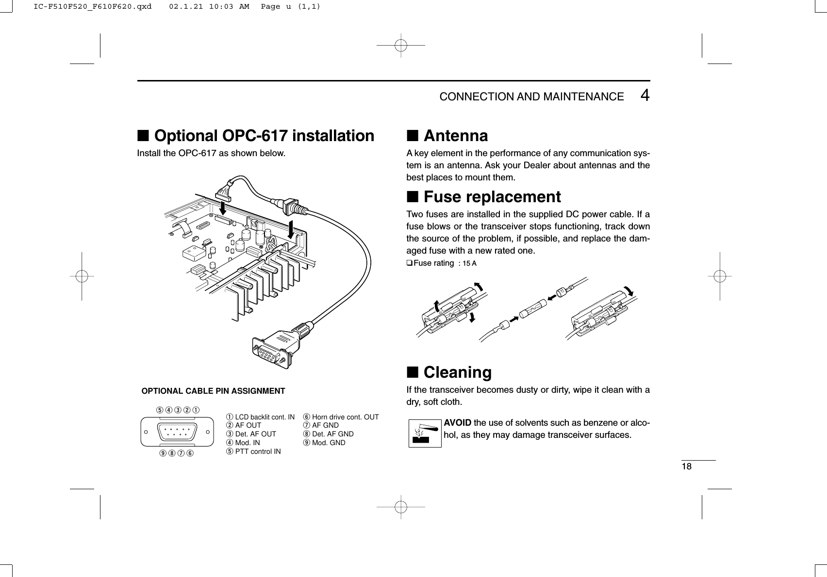
ICOM orporated IC-F621-2 IC-F621-2 User Manual IC F510F520 F610F620

ICOM Incorporated IC-F621-2 IC F510F520 F610F620

Contents

Pages 17 to 24 of the Users Manual

144CONNECTION AND MAINTENANCEqANTENNA CONNECTORConnects to an antenna. Ask your Dealer about antennaselection and placement.wMICROPHONE HANGERConnect the supplied microphone hanger to the vehicle’sground for microphone on/off hook functions. (See p. 2)eDC POWER RECEPTACLEConnects to a 12 V DC battery.  Pay attention to polari-ties. NEVER connect to a 24 V battery. This could dam-age the transceiver.rEXTERNAL SPEAKER JACKConnect a 4–8 Ωexternal speaker, if desired.tOPTIONAL CABLE (OPC-617)Connect an external modem unit, LCD backlight control,etc.■Supplied AccessoriesqMicrophone   ...................... 1wMicrophone hanger and screw set ..................... 1 seteMicrophone hanger cable  . 1rDC power cable (OPC-346)..........................1 tMounting bracket  .............. 1yBracket bolts  ..................... 4uMounting screws (M5×12) . 4iSelf-tapping screws (M5×20) ............................. 4oFlat washers ...................... 4!0 Spring washers  ................. 4!1 Nuts ................................... 4!2 Fuse s (20 A) .....................2!3 Function name stickers*(1705 LCD SEAL(D)) .............1*Function name stickersThere are no names on the programmable function keys since theneeded functions can be assigned to these keys.Attach the supplied function name stickers above the appropriatekeys.qwertyuio!0 !1 !2 !3LCD-STICKERICOMIC-F510F520_F610F620.qxd   02.1.21 10:03 AM  Page q (1,1)
154CONNECTION AND MAINTENANCE■Mounting the transceiverThe front panel can be inverted for correct viewing while leav-ing the built-in speaker facing away from the mounting sur-face.DInverting the Front panelqUnscrew the 2-side screws.wDetach the Front panel forward from the transceiver.eBend the flat cable between Front panel and main unit asshown in the following diagram.rInvert the transceiver 180 degrees clockwise as below.tRe-attach the Front panel to the transceiver.yTighten the 2 screws.CAUTION:•NEVER rotate the transceiver more than 180 degrees.•DO NOT bend the flat cable too hard. Damage may occur.normal bend lineinverted bend lineFlat cable orientationto Front panel to MAIN unitNOTE: Be sure to bend the flat cable in thecorrect direction, before turningover (inverting) the transceiver.IC-F510F520_F610F620.qxd   02.1.21 10:03 AM  Page r (1,1)
164CONNECTION AND MAINTENANCEDMounting the transceiverThe universal mounting bracket supplied with your transceiv-er allows overhead mounting.•Mount the transceiver securely with the 4 supplied screwsto a thick surface which can support more than 1.5 kg.Flat washerSpring washerWhen usingself-tapping screwsIC-F510F520_F610F620.qxd   02.1.21 10:03 AM  Page s (1,1)
174CONNECTION AND MAINTENANCE■Optional UT-105 and UT-108installationThe optional UT-105 and UT-108 units install as follows:qTurn power OFF, then disconnect the DC power cable.wUnscrew the 4 screws, then remove the bottom cover.eInstall the unit as shown in the diagram below.rReplace the bottom cover and screws, then the DC powercable.■Optional UT-109 /UT-110installationqTurn power OFF, then disconnect the DC power cable.wUnscrew the 4 screws, then remove the bottom cover.eCut the print pattern on the PCB at the TX mic circuit (A)and RX AF circuit (B) as shown in the following figure.rInstall the scrambler unit as shown in the left.tReturn the bottom cover and screws to the original posi-tion.NOTE: Be sure to re-solderabove disconnected points, oth-erwise no TX modulation or AFoutput is available when youremove the scrambler units.ABFront panelIC-F510F520_F610F620.qxd   02.1.21 10:03 AM  Page t (1,1)
184CONNECTION AND MAINTENANCE■AntennaA key element in the performance of any communication sys-tem is an antenna. Ask your Dealer about antennas and thebest places to mount them.■Fuse replacementTwo fuses are installed in the supplied DC power cable. If afuse blows or the transceiver stops functioning, track downthe source of the problem, if possible, and replace the dam-aged fuse with a new rated one.❑Fuse rating  : 15 A,■CleaningIf the transceiver becomes dusty or dirty, wipe it clean with adry, soft cloth.AVOID the use of solvents such as benzene or alco-hol, as they may damage transceiver surfaces.qLCD backlit cont. INwAF OUTeDet. AF OUT rMod. INtPTT control INyHorn drive cont. OUTuAF GNDiDet. AF GNDoMod. GNDOPTIONAL CABLE PIN ASSIGNMENT  t r e w q  o i u y■Optional OPC-617 installationInstall the OPC-617 as shown below.IC-F510F520_F610F620.qxd   02.1.21 10:03 AM  Page u (1,1)
195OPTIONSSP-22 EXTERNAL SPEAKERCompact and easy-to-install.Input impedance: 4 ΩMax. input power: 5 WHM-100TNDTMF microphone.SM-25Desktop microphone.UT-105 SmarTrunk II™Logic BoardProvides SmarTrunk II™capabilities.UT-108 DTMF DECODER UNITProvides pager and code squelch capabilities.UT-109/UT-110 (#02) VOICE SCRAMBLER UNIT• UT-109: Non-rolling type (max. 32 codes)• UT-110: Rolling type (max. 1020 codes)UT-111 TRUNKING BOARDProvides trunking oprtation.OPC-617 ACC CABLEAllows you to connect to an external terminal.Icom, Icom Inc. and the  logo are registered trademarks ofIcom Incorporated (Japan) in the United states, the UnitedKingdom, Germany, France, Spain, Russia and/or other coun-tries.SmarTrunk II™is a Trademark of SmarTrunk Systems, Inc.IC-F510F520_F610F620.qxd   02.1.21 10:03 AM  Page v (1,1)
200206SAFETY TRAINING INFORMATIONYour Icom radio generates RF electromag-netic energy during transmit mode. Thisradio is designed for and classified as“Occupational Use Only”, meaning it mustbe used only during the course of employ-ment by individuals aware of the hazards,and the ways to minimize such hazards. This radio isNOT intended for use by the “General Population” in anuncontrolled environment.• For compliance with FCC and Industry Canada RFExposure Requirements, the transmitter antenna installationshall comply with the following two conditions:1. The transmitter antenna gain shall not exceed 0 dBi.2. IC-F521:The transmitter antenna is required to be located outsideof a vehicle and kept at a separation distance of 63 cen-timeters or more between the transmitter antenna of thisdevice and persons during operation.3. IC-F621:The transmitter antenna is required to be located outsideof a vehicle and kept at a separation distance of 50 cen-timeters or more between the transmitter antenna of thisdevice and persons during operation.To ensure that your exposure to RF elec-tromagnetic energy within the FCCallowable limits for occupational use,always adhere to the following guidelines:•DO NOT operate the radio without a proper antennaattached, as this may damage the radio and may also causeyou to exceed FCC RF exposure limits. A proper antenna isthe antenna supplied with this radio by the manufacturer oran antenna specifically authorized by the manufacturer foruse with this radio.•DO NOT transmit for more than 50% of total radio use time(“50% duty cycle”). Transmitting more than 50% of the timecan cause FCC RF exposure compliance requirements tobe exceeded. The radio is transmitting when the “TX indica-tor” lights red. You can cause the radio to transmit by press-ing the “PTT” switch.Electromagnetic Interference/CompatibilityDuring transmissions, your Icom radio generates RF energythat can possibly cause interference with other devices orsystems. To avoid such interference, turn off the radio inareas where signs are posted to do so. DO NOT operate thetransmitter in areas that are sensitive to electromagnetic radi-ation such as hospitals, aircraft, and blasting sites.WARNINGCAUTIONIC-F510F520_F610F620- 2.qxd   02.2.4 5:22 PM  Page w (1,1)
Count on us!1-1-32 Kamiminami, Hirano-ku, Osaka 547-0003 JapanA-6120H-1EXPrinted in Japan©2002 Icom Inc.                  (45W/50W)IC-F510F520_F610F620.qxd   02.1.21 10:03 AM  Page Z (1,1)

Navigation menu